sicoma zhuhai co., ltd. - tunengineering€¦ · sicoma zhuhai co., ltd. ... 7.3.1) pre-mixed...
TRANSCRIPT
SICOMA ZHUHAI CO., LTD.
ATTENTION: THE NON-APPLICATION OF THE USE AND MAINTENANCE RULES MENTIONED WITH THE PRESENT MANUAL WILL ENTAIL THE AUTOMATIC LOSS OF ALL WARRANTY INSURANCE COVERINGS.

2
PROGRESSIVE INDEX INTRODUCTION CONDITIONS OF GUARANTEE
DIMENSIONS SCHEME
MACHINE SCHEME
TECHNICAL SPECIFICATION
INSTRUCTIONS FOR USE AND MAINTENANCE
1) PRODUCER INFORMATION
2) HOW TO USE AND KEEP THE INSTRUCTION MANUAL
2.1) PURPOSE OF THE INFORMATION IN THE INSTRUCTION MANUAL 2.2) INTENDED USER OF THE INSTRUCTION MANUAL 2.3) INSTRUCTION MANUAL APPLICATION 2.4) INSTRUCTION MANUAL LIMITATIONS 2.5) HOW TO PERSERVE THE INSTRUCTION MANUAL 2.6) WARNINGS 3) MOVING AND INSTALLING THE MACHINE
3.1) ON RECEIVING THE MACHINE 3.2) PERSONNEL REQUIREMENTS 3.3) INSTRUCTIONS FOR LIFTING AND MOVING THE MACHINE 3.4) STATIC AND DYNAMIC LOADS 3.5) CHECKING OIL AND HYDRAULIC FLUID LEVELS 4) ELECTRICAL CONNECTIONS
4.1) ELECTRICAL CONNECTIONS 4.2) JUNCTION BOX 4.3) ELECTRICITY SUPPLY CONNECTIONS AND EARTH 4.4) MIXING ARM ALIGNMENT 4.5) MOTOR REVOLUTION DIRECTION CHECK 5) USES FOR THE MACHINE
5.1) WHAT IS THE MACHINE FOR 5.2) INTENDED USE OF THE MACHINE 5.3) OPERATOR 5.4) MATERIALS THAT MAY BE USED IN THE MACHINE 5.5) RESTRICTIONS OF USE 5.6) WORKING ENVIRONMENT 6) TECHNICAL DESCRIPTION OF THE MACHINE
6.1) DESCRIPTION OF THE MACHINE 6.1.1) MIXING TANK 6.1.2) MIXING SYSTEM 6.1.3) TRANSMISSION 6.1.4) UNLOADING

3
6.1.5) ELECTRIC CONTROL 6.2) MIXING PROCEDURE 6.3) TECHNICAL DIAGRAMS 6.3.1) JUNCTION BOX DIAGRAM 6.3.2) HYDRAULIC DIAGRAM 6.4) SOUND TEST 6.4.1) MACHINE OPERATING CONDITIONS
6.4.2) MEASURING CONDITIONS 6.4.3) AVERAGE Leq ( A ) 7) INSTRUCTIONS FOR USE
7.1) OPERATION PROCEDURE 7.2) LOADING PHASE 7.3) MIXING PHASE 7.3.1) PRE-MIXED MIXTURE FOR TRUCK MIXER’S LOADING 7.3.2) MIXED MIXTURE FOR PRODUCERD AND PREFABRICATED
ELEMENTS 7.4) BELT LOADING PHASE 7.5) UNLOADING PHASE
7.6) CLEANING
8) SAFETY DEVICES: CHECKING AND ADJUSTMENT 8.1) SAFETY DEVICE
8.1.1) RELIEF VALVE 8.1.2) CHECKING COVER SAFETY SWITCH
9) MAINTENANCE INSTRUCTION
9.1) CHANGING THE LUBIRCATING OIL 9.2) CHANGING THE HYDRAULIC OIL 9.3) GREASING MIXER PARTS
9.4) GREASING GEARBOX PARTS 9.5) CHECKING BOLT TIGHTNES 9.6) CHECKING OF PARTS SUBJECT TO WEAR 9.7) ADJUSTING MIXING BLADE
9.7.1) ADJUSTING MIXING ARMS AND BOTTOM SHOVEL 9.7.2) ADJUSTING MIXING PERIPHERAL SHOVELS 9.8) ADJUSTING AND RESETTING THE SEAL ON THE DISCHARGE OPERATION
9.9) FIXING OIL LEAKS BETWEEN THE FIXED REDUCTION GEARBOX AND THE COVER OF THE ROTATING PLANETARY GEARBOX
9.10) TROUBLE SHOOTING GUIDE 9.11) MOTOR MAINTENANCE AND REPAIR
10) SPARE PARTS MANUAL 10.1) GENERAL
10.2) HOW TO ORDER SPARE PARTS

4
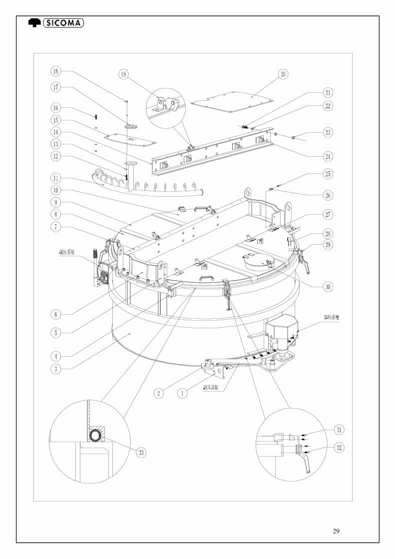
SPARE PARTS MPC750/500 MIXER ASSEMBLY SCHEME MPC750/500 LININGS MPC750/500 MIXING ARMS AND SCRAPER ARMS MPC750/500 DISCHARGE DOOR GEARBOX GREASING INSTRUCTION RM057 MAIN GEARBOX RM057 PLANETARY GEARBOX DISCHARGE DOOR LIMIT SWITCH DIAGRAM DISCHARGE DOOR HYDRAULIC CONTROL DIAGRAM

5
INTRODUCTION
Dear Customer, SICOMA ZHUHAI CO., LTD would like to thank you for purchasing this product and invite you to: - Read the instructions in this manual: they give the sequence of checks and
preliminary work required for transport, installation, use and maintenance of the machine and a series of tables complete with lists for easy identification and ordering of spare parts.
- If there are any problems, contact the producer or area representative. - In order not to damage the machine or impair its correct operation, we recommend
using ORIGINAL spare parts.
CONDITIONS OF GUARANTEE The guarantee period of 36 months applies to a single shift (8 hours) per working day. The machine is guaranteed for a period of 36 (thirty-six) months, for the mixing group gear reducer As regards all the other mechanical parts, the guarantee is of 12 (twelve) months starting from the beginning of production. However this starting date begin after a maximum of 6 (six) months from the date of delivery to the user. For electrical parts see separate producer’s guarantee. The guarantee includes:
a) Free replacement or repair of parts found to be faulty due to manufacturing defects
(except the particulars subject to wear and tear). b) The guarantee ceases immediately if the machine, or one of its components, is
damaged by: Negligent use. Dismantling, repair, or modification by unauthorised persons. Transporting without due care. Causes not attributable to manufacturing defects.
c) Extension of the guarantee after an intervening fault is excluded, transport and travel expenses are paid by the customer, while on-site working hours are included in the guarantee.
d) Also excluded are cancellation of contract, compensation for working hours lost, non production, and direct or indirect damage to persons or things caused by the improper use of the machine.

6
DIMENSIONS SCHEME
Fig 1 Dimensions in mm. They can be changed for technical reasons
7
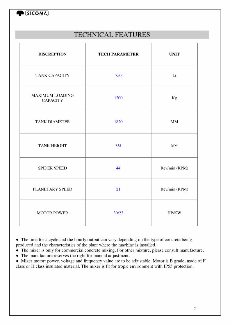
TECHNICAL FEATURES
DISCREPTION TECH PARAMETER UNIT
TANK CAPACITY 750 Lt
MAXIMUM LOADING CAPACITY 1200 Kg
TANK DIAMETER 1820 MM
TANK HEIGHT 835 MM
SPIDER SPEED 44 Rev/min (RPM)
PLANETARY SPEED 21 Rev/min (RPM)
MOTOR POWER 30/22 HP/KW
● The time for a cycle and the hourly output can vary depending on the type of concrete being produced and the characteristics of the plant where the machine is installed. ● The mixer is only for commercial concrete mixing. For other mixture, please consult manufacture. ● The manufacture reserves the right for manual adjustment. ● Mixer motor: power, voltage and frequency value are to be adjustable. Motor is B grade, made of F class or H class insulated material. The mixer is fit for tropic environment with IP55 protection.
8
1) PRODUCER INFORMATION
SICOMA ZHUHAI CO., LTD ADDRESS: NO. 7 PINGGONG ROAD (WEST), NANPING SCIENCE & TECHNOLOGY INDUSTRIAL PARK, ZHUHAI, CHINA POSTALCODE: 519060 TEL: 86-756-8682100 86-4008870883 FAX: 86-756-8682101 86-756-8682748
9
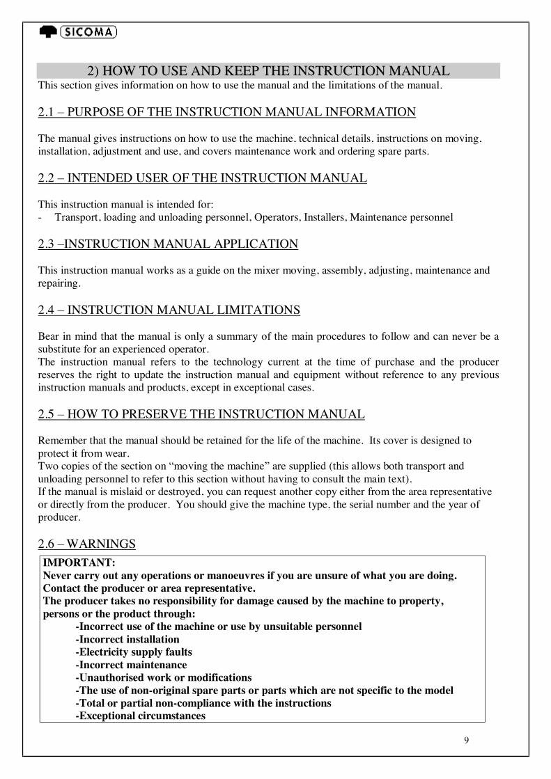
2) HHOOWW TTOO UUSSEE AANNDD KKEEEEPP TTHHEE IINNSSTTRRUUCCTTIIOONN MMAANNUUAALL This section gives information on how to use the manual and the limitations of the manual. 2.1 – PURPOSE OF THE INSTRUCTION MANUAL INFORMATION The manual gives instructions on how to use the machine, technical details, instructions on moving, installation, adjustment and use, and covers maintenance work and ordering spare parts. 2.2 – INTENDED USER OF THE INSTRUCTION MANUAL This instruction manual is intended for: - Transport, loading and unloading personnel, Operators, Installers, Maintenance personnel 2.3 –INSTRUCTION MANUAL APPLICATION This instruction manual works as a guide on the mixer moving, assembly, adjusting, maintenance and repairing. 2.4 – INSTRUCTION MANUAL LIMITATIONS Bear in mind that the manual is only a summary of the main procedures to follow and can never be a substitute for an experienced operator. The instruction manual refers to the technology current at the time of purchase and the producer reserves the right to update the instruction manual and equipment without reference to any previous instruction manuals and products, except in exceptional cases. 2.5 – HOW TO PRESERVE THE INSTRUCTION MANUAL Remember that the manual should be retained for the life of the machine. Its cover is designed to protect it from wear. Two copies of the section on “moving the machine” are supplied (this allows both transport and unloading personnel to refer to this section without having to consult the main text). If the manual is mislaid or destroyed, you can request another copy either from the area representative or directly from the producer. You should give the machine type, the serial number and the year of producer. 2.6 – WARNINGS IMPORTANT: Never carry out any operations or manoeuvres if you are unsure of what you are doing. Contact the producer or area representative. The producer takes no responsibility for damage caused by the machine to property, persons or the product through: -Incorrect use of the machine or use by unsuitable personnel -Incorrect installation -Electricity supply faults -Incorrect maintenance -Unauthorised work or modifications -The use of non-original spare parts or parts which are not specific to the model -Total or partial non-compliance with the instructions -Exceptional circumstances
10
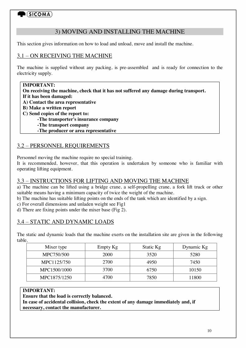
3) MOVING AND INSTALLING THE MACHINE This section gives information on how to load and unload, move and install the machine. 3.1 – ON RECEIVING THE MACHINE The machine is supplied without any packing, is pre-assembled and is ready for connection to the electricity supply.
IMPORTANT: On receiving the machine, check that it has not suffered any damage during transport. If it has been damaged: A) Contact the area representative B) Make a written report C) Send copies of the report to: -The transporter's insurance company -The transport company -The producer or area representative
3.2 – PERSONNEL REQUIREMENTS Personnel moving the machine require no special training. It is recommended, however, that this operation is undertaken by someone who is familiar with operating lifting equipment. 3.3 – INSTRUCTIONS FOR LIFTING AND MOVING THE MACHINE a) The machine can be lifted using a bridge crane, a self-propelling crane, a fork lift truck or other suitable means having a minimum capacity of twice the weight of the machine. b) The machine has suitable lifting points on the ends of the tank which are identified by a sign. c) For overall dimensions and unladen weight see Fig1 d) There are fixing points under the mixer base (Fig 2). 3.4 – STATIC AND DYNAMIC LOADS The static and dynamic loads that the machine exerts on the installation site are given in the following table.
Mixer type Empty Kg Static Kg Dynamic Kg MPC750/500 2000 3520 5280 MPC1125/750 2700 4950 7450
MPC1500/1000 3700 6750 10150 MPC1875/1250 4700 7850 11800
IMPORTANT: Ensure that the load is correctly balanced. In case of accidental collision, check the extent of any damage immediately and, if necessary, contact the manufacturer.
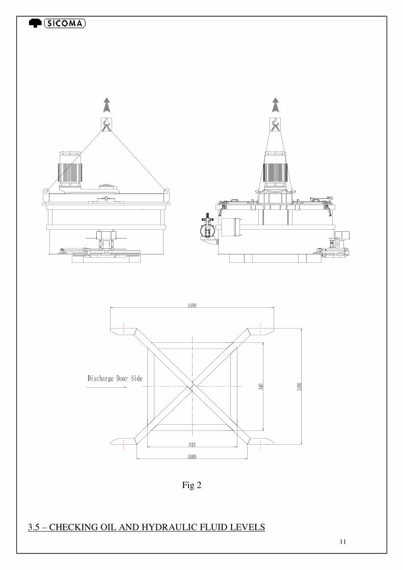
11
Fig 2 3.5 – CHECKING OIL AND HYDRAULIC FLUID LEVELS
12
IMPORTANT: On receiving the machine (and therefore before it is started), check the oil level in the mixing units and hydraulic pump. If, for transport purposes, the machine is dispatched lying on the side, neither the gearboxes nor the pump will contain oil. These reducers must be filled before the installation.
4) ELECTRICAL CONNECTIONS
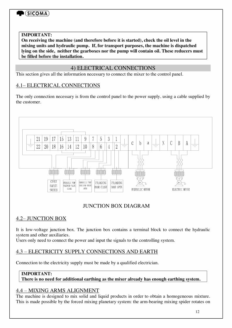
This section gives all the information necessary to connect the mixer to the control panel. 4.1– ELECTRICAL CONNECTIONS The only connection necessary is from the control panel to the power supply, using a cable supplied by the customer.
JUNCTION BOX DIAGRAM 4.2– JUNCTION BOX It is low-voltage junction box. The junction box contains a terminal block to connect the hydraulic system and other auxiliaries. Users only need to connect the power and input the signals to the controlling system. 4.3 – ELECTRICITY SUPPLY CONNECTIONS AND EARTH Connection to the electricity supply must be made by a qualified electrician.
IMPORTANT: There is no need for additional earthing as the mixer already has enough earthing system.
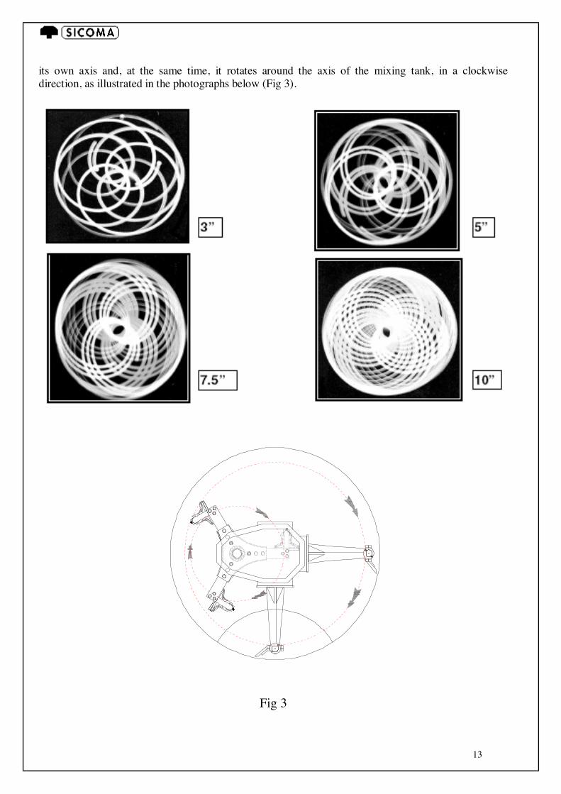
4.4 – MIXING ARMS ALIGNMENT The machine is designed to mix solid and liquid products in order to obtain a homogeneous mixture. This is made possible by the forced mixing planetary system: the arm-bearing mixing spider rotates on
13
its own axis and, at the same time, it rotates around the axis of the mixing tank, in a clockwise direction, as illustrated in the photographs below (Fig 3).
Fig 3
14
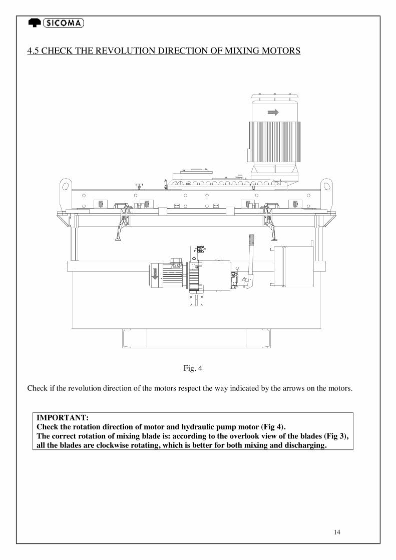
4.5 CHECK THE REVOLUTION DIRECTION OF MIXING MOTORS
Fig. 4
Check if the revolution direction of the motors respect the way indicated by the arrows on the motors.
IMPORTANT: Check the rotation direction of motor and hydraulic pump motor (Fig 4). The correct rotation of mixing blade is: according to the overlook view of the blades (Fig 3), all the blades are clockwise rotating, which is better for both mixing and discharging.
15
5) USES FOR THE MACHINE
This section gives general information on the uses for the machine and describes the main functions and restrictions as to use. 5.1 – WHAT IS THE MACHINE DESIGNED FOR The machine has been designed for mixing materials of different natural and chemical types (the substances which may be used are detailed below). Owing to the specialized nature of the machine, it is not possible to use it for other purposes and the producer does not recommend other methods of use, as directed in point 1.1.2, letter C of 89/392 CEE. 5.2 – INTENDED USE OF THE MACHINE The machine is designed for industries of concrete products, fire-resistance materials, ceramics, etc.. 5.3 – OPERATOR No special technical knowledge is required to use the machine. A careful reading of this manual is sufficient. It should be borne in mind, however, that it is very important to have both experience and a knowledge of the product(s) being used. 5.4 – MATERIALS THAT MAY BE USED IN THE MACHINE Inert substances in powder or granular form with particles having a maximum of 150 mm and a maximum quantity of 12% of the total, concrete, lime and mortar, refractory substances, chemical colorants, silica sand, resins, etc., with or without the addition of liquids such as water, additives, etc.. 5.5 – RESTRICTIONS OF USE Inert substances with a grain size of more than 150 mm and in a quantity higher than 12% of the total. Clays with a humidity rate of approximately 15%. Semi-dry concrete mixture, although homogeneous, can cause the mixing shafts to increase in diameter due to material adhering to them. This reduces the mixing force of the arms. In this case it is essential to equip the machine with a cleaning system. 5.6 – WORKING ENVIRONMENT On request, it can be supplied with systems which enable it to be used in environments where there are explosives and extremely harmful materials such as salts, acids and alkalines. Using the machine outdoors poses no particular problems. It is advisable, however, to put a protective cover over the electrical components.
16
6) TECHNICAL DESCRIPTION OF THE MACHINE This section provides a technical summary of the machine and how it works. It details everything the operator and maintenance personnel need to know in order to understand how the machine works and how to quickly identify possible faults and malfunctions. 6.1 – DESCRIPTION OF THE MACHINE 6.1.1) MIXING TANK SYSTEM: a) MIXING TANK: made of very thick steel sheets on a frame of U-type sections allowing several discharges. b) TANK BOTTOM AND WALLS: made of very thick sheets of Fe 52 with 120 HB resistance, with interchangeable and bolted sectors. On request a special anti-wear lining of CR 321 with 300HB resistance or, only for the bottom, of CR 6000 with 460 HB resistance. c) COVER: made of cover, inspection door, inspection window, safety switch etc. The main function is for sealing, material feeding and inspection. 6.1.2) MIXING SYSTEM It is composed of reducer beam, mixing arms, scraper arms, mixing blades and wear linings (anti-wear linings). the machine is designed to mix solid and liquid products in order to obtain a homogeneous mixture. This is made possible by the forced mixing planetary system: the arm-bearing mixing spider rotates on its own axis and, at the same time, it rotates around the axis of the mixing tank, in a clockwise direction. 1. SPIDER: made of anti-wear ductile cast iron. 2. SUPPORT OF OUTER ARMS: Mixing Arm: made of super quality steel plate and welded. 3. SCRAPER ARMS: made of super quality steel plate and welded. 4. MIXING BLADES: composed of outer shovels and blades 5. SIDE LININGS: made of middle-chrome alloy cast iron 6. BOTTOM LININGS: made of anti-wear high-chrome cast iron 7. DISCHARGE GATE: it is a sector at the bottom of the tank (there are three options for opening
gate position). It is operated by hydraulic oil pump or manual pump, whose position can be controlled by limit switches (two positions: open or close).
6.1.3) TRANSIMISSION SYSTEM It is composed by mixing motors, main gearbox and gearbox support. 1. MIXING MOTORS: 4-Pole motor. 4-pole 1470R/Min. The power, voltage and frequency are
variable. It is in F class insulators, tropicalized and with an IP55 protection. It is recommended not to start the motors when the tank is loaded. Open the unloading door by electric or manual emergency pump to unload the materials first before starting motor.
2. MIXING REDUCTION UNIT: has incorporated planetary gearing and is the heart of the machine.
It has been specially developed over the years to stand up to severe stress and tough working

17
conditions as well as for use during non-stop work shifts. The bolted-on reduction-gear housing is supported by a frame, is easy to disassemble and is bridge-mounted on the mixing tank. The reduction unit case is made in modular cast iron with an iron-perlite base. The helical gears, which are more resistant, guarantee low noise level even at high rotation speeds and are of 18NCD5 case-hardened steel. With thermal treatment, the resistance on the surface of the teeth has a hardness of 58-60 Rc. The torsion shafts are made from 39NCD3 tempered steel with an average resistance of 90 Kg/mm². The bearings all have tapered rollers to ensure greater static and dynamic loading and are adjustable. The reduction gears operate in an oil bath (Engler EP150) ensuring maximum lubrication in conditions of extreme pressure on the teeth. The reduction unit may be connected to the motor via a hydraulic coupling. This facilitates starting the machine even with a full load.
3. GEARBOX SUPPORT: With C-shaped steel frame structure, it is bridged on the mixer tank by the connection of bolt to the gearbox outer case supported by frame. It is designed to give maximum stability and protection for the gearbox. 6.1.4) UNLOADING SYSTEM Composed by discharge door, hydraulic oil tank, hydraulic pump and limit switch. At automatic mode, there are two-position settings: open and close. 1. DISCHARGE DOOR: It is composed by discharge door, liners and bearings. The gap between the mixing tank and the discharge door should be within 1-3mm. The discharge door should be cleaned periodically to prevent concrete accumulation and ensure a smooth door operation. 2. HYDRAULIC PUMP:
18
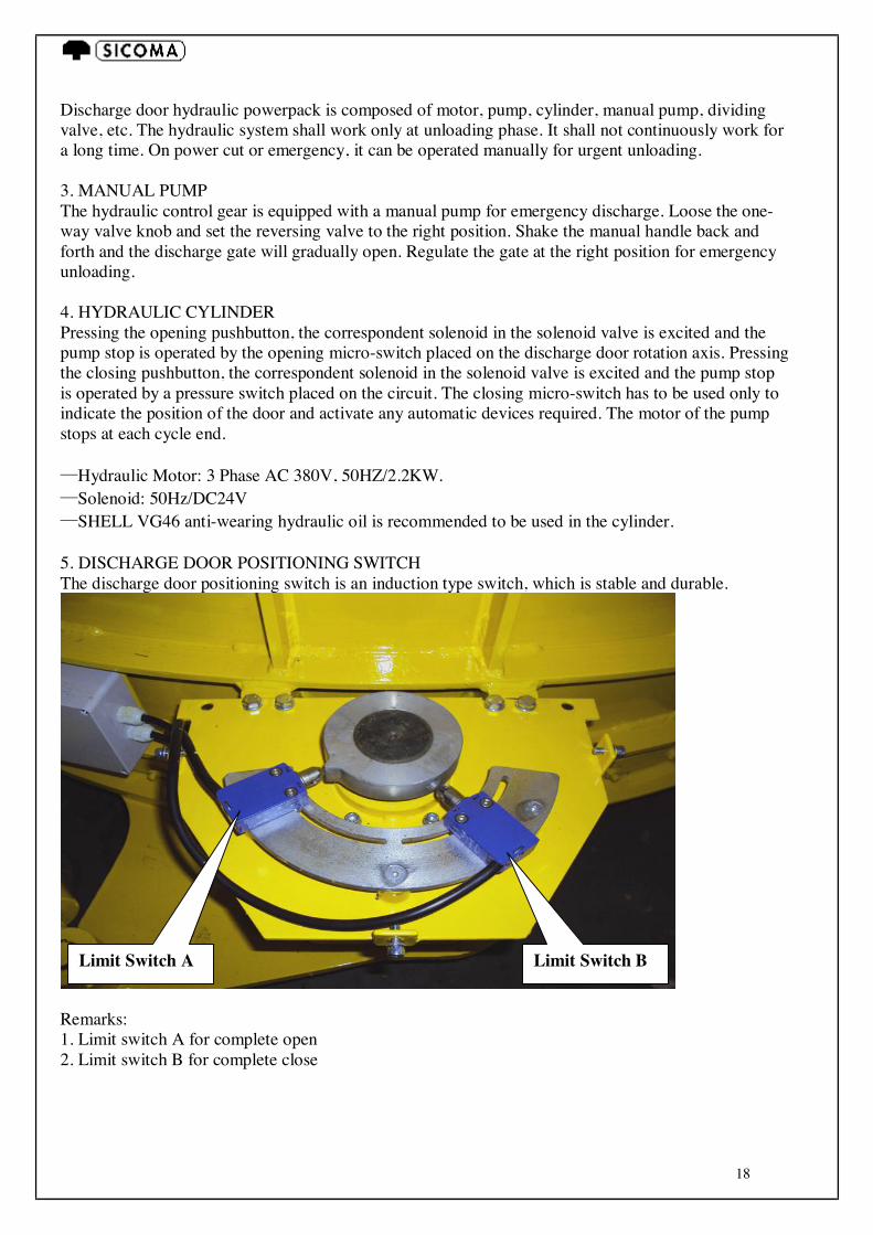
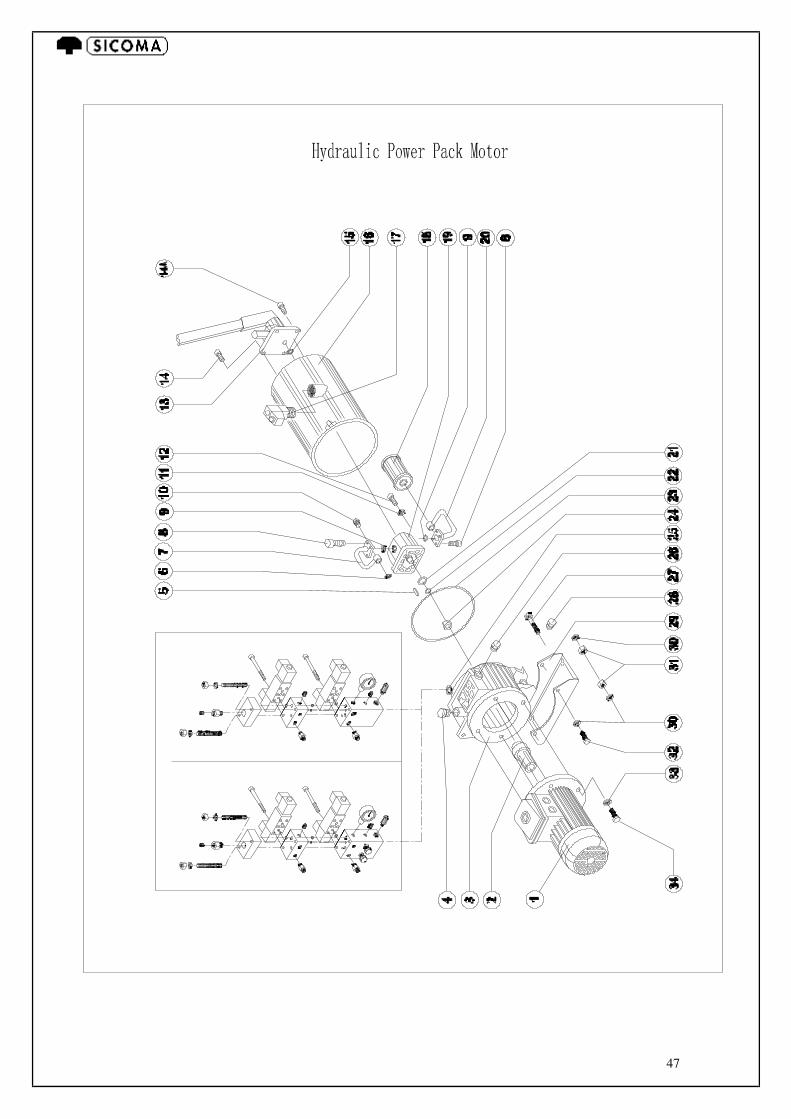
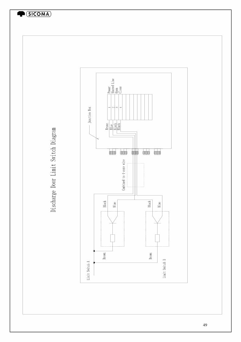
Discharge door hydraulic powerpack is composed of motor, pump, cylinder, manual pump, dividing valve, etc. The hydraulic system shall work only at unloading phase. It shall not continuously work for a long time. On power cut or emergency, it can be operated manually for urgent unloading. 3. MANUAL PUMP The hydraulic control gear is equipped with a manual pump for emergency discharge. Loose the one-way valve knob and set the reversing valve to the right position. Shake the manual handle back and forth and the discharge gate will gradually open. Regulate the gate at the right position for emergency unloading. 4. HYDRAULIC CYLINDER Pressing the opening pushbutton, the correspondent solenoid in the solenoid valve is excited and the pump stop is operated by the opening micro-switch placed on the discharge door rotation axis. Pressing the closing pushbutton, the correspondent solenoid in the solenoid valve is excited and the pump stop is operated by a pressure switch placed on the circuit. The closing micro-switch has to be used only to indicate the position of the door and activate any automatic devices required. The motor of the pump stops at each cycle end. —Hydraulic Motor: 3 Phase AC 380V, 50HZ/2.2KW. —Solenoid: 50Hz/DC24V —SHELL VG46 anti-wearing hydraulic oil is recommended to be used in the cylinder. 5. DISCHARGE DOOR POSITIONING SWITCH The discharge door positioning switch is an induction type switch, which is stable and durable.
Remarks: 1. Limit switch A for complete open 2. Limit switch B for complete close
Limit Switch B Limit Switch A
19
6.1.5) ELECTRIC CONTROL SYSTEM It is composed by motor control, discharge door control, cover safety device control, junction box, etc.. a) Mixing motor control circuit is supplied by the customer. b) Discharge door control circuit is supplied by the customer. The producer gives a reference as attached. The wire connection terminals are ready for connection. c) Cover Safety Control: With the cover safety device, when the inspection window of the cover is opened, the main motor cannot operate. It ensures the operator safety in case of maintenance and repair. d) Junction Box: it has terminals to connect the discharge door, cover safety device and discharge door limit switch. The diagrams are attached for reference. 6.2— SEQUENCE OF OPERATIONS DURING THE MIXING CYCLE: .Start up of mixing motor. .Closure of unloading door. .Introduction of granular and/or powder material. .Dry mixing. .Introduction of water, chemical additives and colorants (if required). .Final mixing. .Unloading of mixture. .Cleaning of tank and mixer parts with manual or automatic cleaning system (if fitted).
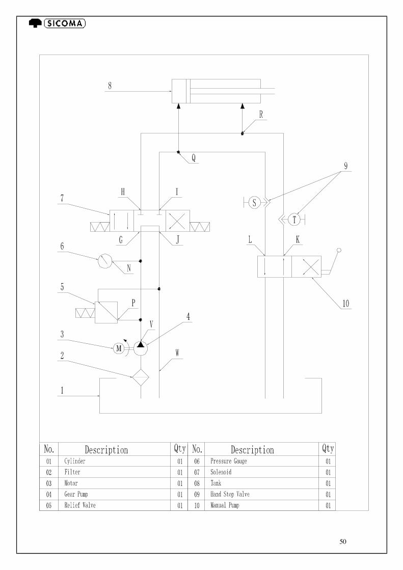
6.3 —TECHNICAL DIAGRAMS AND TABLES 6.3.1) JUNCTION BOX DIAGRAM Circuit diagram as attached. 6.3.2) HYDRAULIC DIAGRAM Hydraulic diagram as attached. 6.4—SOUND TESTS 6.4.1) MACHINE OPERATING CONDITIONS The mixer during the mixing phase
6.4.2) MEASURING CONDITIONS Because each work site is different, noise-level measurements is taken 1 meter from the vertical surface of the machine, 1.60 meters above ground level.
6.4.3) AVERAGE Leq ( A ) Leq = 70 dB ( A )
7) INSTRUCTION FOR USE This section details the correct use of the machine. 7.1 USING THE MACHINE The main mixing phases (described in brief in the preceding section) are: The loading phase. The mixing phase. The unloading phase. Cleaning.

20
7.2 LOADING PHASE WITH MOBILE OR FIXED SKIP a) Check that the mixing tank is empty. b) Close the protective machine guards by blocking them through the safety device with which the
machine is equipped. c) Close the mixer unloading door by pressing the appropriate push button. d) Start the mixing motor by pressing the appropriate push button. e) Begin to load the machine by pressing the appropriate push buttons.
We recommend introducing cement in the center of the mixer using a screw feeder so that loading takes place gradually in about 15". This avoids clusters of material accumulating which prolong mixing time and cause lumps to form. 7.3 RECOMMENDED MIXING PHASE FOR:
PREMIXED MIXTURE FOR TRUCK MIXER’S LOADING a) Dry mix for 15".
b) Inlet water (it can be input both at network supply standard or high pressure piping); average water inlet duration 10”. c) Mixing: 40” if the concrete is destined to transportation with mixing truck, 60” if destined to
direct use for casting or prefab, mixing time increases in case of humidity detection by means of a probe.
d) Time to unload mixture: 10". f) Time required for closing unloading door: 3". 7.4 CONVEYOR LOADING PHASE Conveyor loading time counts as dry premix phase and cement can be introduced simultaneously with the aggregates. As soon as the cement scale display marks 0 (zero), water can be introduced. Loading and pre-mixing time varies according to the capacity of the conveyor belt, therefore only 15” of final pre-mixing is sufficient to obtain perfect homogeneousness of mixture. Discharge and outlet opening times are not changed. 7.5 UNLOADING PHASE
IMPORTANT: in case the mixer is equipped with more than one outlet and if only one of them is currently used, it is possible that the others tend to rotate towards the opening position under the pressure exerted by the mixing and side arms at ever turn over such outlet doors it is wise to carry out a complete opening and closing for every hour of operation in order to restore correct sealing of the rubber gaskets, or to perform correct repositioning of the end-switch for the out lets not provided with gaskets.
a) The discharge time is 20” for repeated cycles, or of 40” to obtain full discharge of the tank. b) Outlet closing requires goes from 2” for the pneumatic-operated model to an average of 4” for
the hydraulic-operated model. c) Every cycle lasts as a whole from 90” to 120”.
7.6) CLEANING To remove traces of mixture, clean the shafts, arms and blades at the end of the work cycle.
IMPORTANT: We recommend the use of an automatic cleaning system (supplied on request) which cleans the mixing components at the end of the unloading phase before a new mixing cycle begins. Where manual cleaning takes place, DO NOT USE A HAMMER to remove traces of mixture. Striking the blades violently can break them.
21
IMPORTANT: Where a black-out should occur, before re-starting mixing motors, it is important to empty the mixing tank by opening the discharge door with the emergency manual pump situated on the hydraulic.
IMPORTANT: Make sure the power is cut before getting into the mixer for cleaning.
8) SAFETY DEVICES: CHECKING AND ADJUSTMENT
8.1 – SAFETY DEVICES 8.1.1) MAXIMUM PRESSURE VALVE AND PRESSURE SWITCH a) The hydraulic circuit is equipped with a valve to protect against any pressure increases which could damage system components. b) At least once a year, check that the maximum pressure safety valve is functioning correctly. This valve is on the main hydraulic unit. The valve is set for 100 bar and has been tested prior to being fitted to the machine. Check as follows: a) Loosen the nut on the control screw (this screw has a hexagonal recess) situated on the electro
valve unit. b) Turn the screw clockwise one revolution. c) Check that the pressure gauge shows a rise in pressure.
d) Turn the screw back to the original position and tighten the nut.
IMPORTANT: If the pressure shown on the pressure gauge does not vary, change the valve.
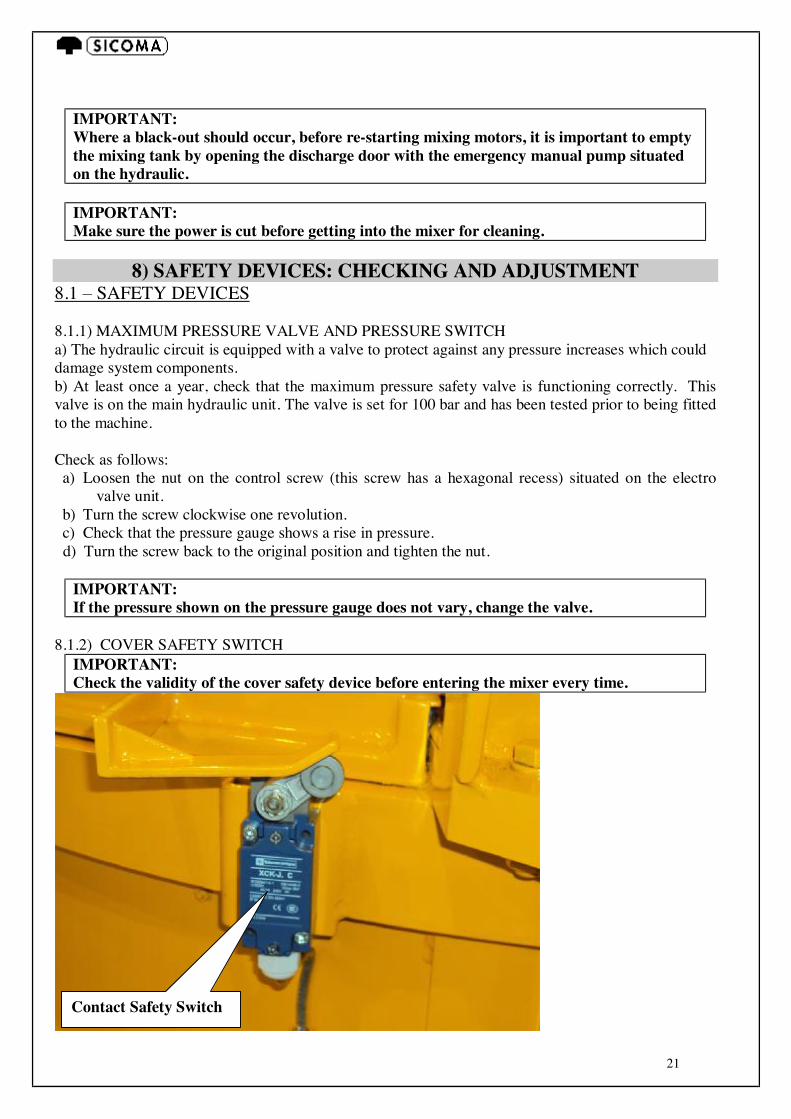
8.1.2) COVER SAFETY SWITCH
IMPORTANT: Check the validity of the cover safety device before entering the mixer every time.
Contact Safety Switch
22
It is emphasized by SICOMA that the below procedure must be strictly followed before the operator enters the mixer. 1. Cut the motor power of the controlling cabinet first. Give the key to the operator who is to enter the mixer. 2. Open the inspection door and keep the contacting switch in break mode. 3. Double check if the motor cannot be activated and then enter the mixer. 4. After maintenance, make sure there are no people or other things (tools or accessories) left before connecting the motor power.
9) MAINTENANCE INSTRUCTIONS The machine has been designed and constructed so as to reduce maintenance to a minimum. This section gives information on ordinary maintenance to be carried out at set intervals. When performing any type of intervention, the following safety standards must be followed: · Machine cleaning and maintenance (mixer and skip) must be done while the electrical power is off (using the isolator switch on the control panel), as well as the pneumatic and hydraulic supplies. · Before starting any type of maintenance, set out placards indicating MACHINE MAINTENANCE. Place the signs in clearly visible areas. ·Keep unauthorized personnel away from the work area. ·Wear suitable work garments (overalls, gloves, boots) without any loose ends. ·The electrical control panel must be opened only after the machine is off and once a sufficient amount of time has elapsed for the electrical equipment to cool. ·Do not use solvents, inflammable materials or water to clean and maintain the electrical panel. ·Do not smoke or use open flames around inflammable materials such as rubber, oil, plastic, etc. ·Do not modify, alter or tamper with the hydraulic circuit in any way, nor with the electrical parts, moving parts, cables, safety devices or electrical wiring. ·Avoid getting into contact with hydraulic fluids and dispose of them properly, especially during filling, recuperation and repair operations. In case any leaks should occur, be sure to wear rubber gloves when changing the oil. ·At the end of maintenance, repair or cleaning operations, restore the refasten all the guarding and protective casings that may have been opened or removed. ·Used oil must be disposed of in closed containers and redelivered to your usual supplier or to competent public agencies so that can be disposed of as provided for by law.
IMPORTANT: Before undertaking any work, turn off the power using the isolating switch on the control panel.
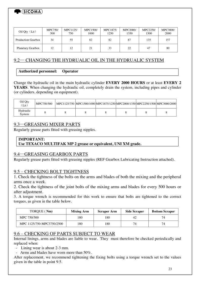
9.1— CHANGING THE LUBIRCATING OIL
Authorized personnel: Operator
Change the oil in the reduction gearboxes EVERY 4000 HOURS or at least EVERY 2 YEARS.
IMPORTANT: Use ROL EP 150 oil or equivalent, UNI CC 150 grade.
23
Oil Qty(Lit) MPC750/
500 MPC1125/
750 MPC1500/
1000 MPC1875/
1250 MPC2000/
1350 MPC2250/
1500 MPC3000/
2000
Production Gearbox 34 55 82 82 87 135 157
Planetary Gearbox 12 12 21 33 22 47 80
9.2— CHANGING THE HYDRUALIC OIL IN THE HYDRUALIC SYSTEM
Authorized personnel: Operator Change the hydraulic oil in the main hydraulic cylinder EVERY 2000 HOURS or at least EVERY 2 YEARS. When changing the hydraulic oil, completely drain the system, including pipes and cylinder (or cylinders, depending on equipment).
Oil Qty(Lit) MPC750/500 MPC1125/750 MPC1500/1000 MPC1875/1250 MPC2000/1350 MPC2250/1500 MPC3000/2000
Hydraulic System 8 8 8 8 8 8 8
9.3—GREASING MIXER PARTS Regularly grease parts fitted with greasing nipples.
IMPORTANT: Use TEXACO MULTIFAK MP 2 grease or equivalent, UNI XM grade.
9.4—GREASING GEARBOX PARTS Regularly grease parts fitted with greasing nipples (REF Gearbox Lubricating Instruction attached). 9.5 – CHECKING BOLT TIGHTNESS 1. Check the tightness of the bolts on the arms and blades of both the mixing and the peripheral arms once a week. 2. Check the tightness of the joint bolts of the mixing arms and blades for every 500 hours or after adjustment. 3. A torque wrench is recommended for this work to ensure that bolts are tightened to the correct torques, as given in the table below.
TORQUE ( Nm) Mixing Arm Scraper Arm Side Scraper Bottom Scraper MPC 750/500 180 180 42 74 MPC 1125/750-MPC3750/2500 180 180 74 74
9.6 – CHECKING OF PARTS SUBJECT TO WEAR Internal linings, arms and blades are liable to wear. They must therefore be checked periodically and replaced when: - Lining wear is about 2-3 mm.
- Arms and blades have worn more than 50%. After replacement, we recommend tightening the fixing bolts using a torque wrench set to the values given in the table in point 9.5.
24
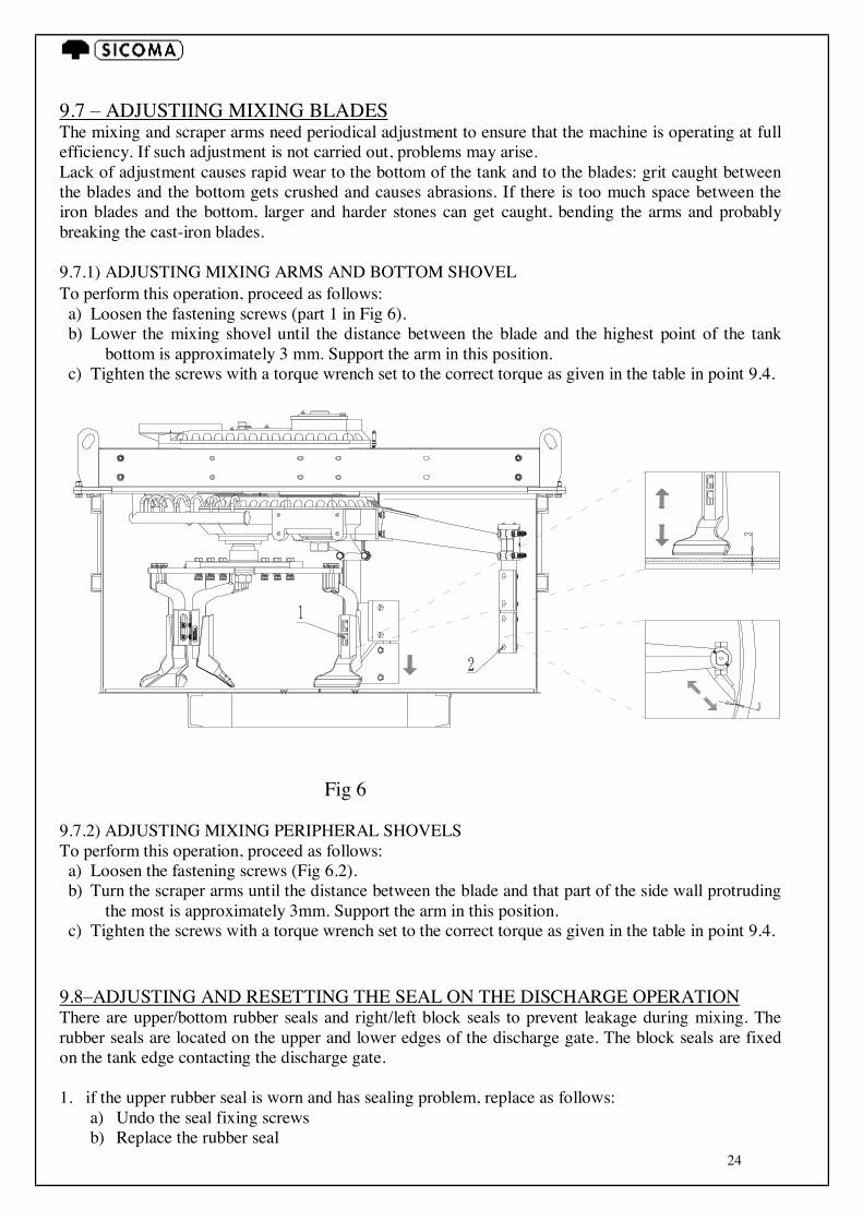
9.7 – ADJUSTIING MIXING BLADES The mixing and scraper arms need periodical adjustment to ensure that the machine is operating at full efficiency. If such adjustment is not carried out, problems may arise. Lack of adjustment causes rapid wear to the bottom of the tank and to the blades: grit caught between the blades and the bottom gets crushed and causes abrasions. If there is too much space between the iron blades and the bottom, larger and harder stones can get caught, bending the arms and probably breaking the cast-iron blades. 9.7.1) ADJUSTING MIXING ARMS AND BOTTOM SHOVEL To perform this operation, proceed as follows: a) Loosen the fastening screws (part 1 in Fig 6). b) Lower the mixing shovel until the distance between the blade and the highest point of the tank
bottom is approximately 3 mm. Support the arm in this position. c) Tighten the screws with a torque wrench set to the correct torque as given in the table in point 9.4.
Fig 6 9.7.2) ADJUSTING MIXING PERIPHERAL SHOVELS To perform this operation, proceed as follows: a) Loosen the fastening screws (Fig 6.2). b) Turn the scraper arms until the distance between the blade and that part of the side wall protruding
the most is approximately 3mm. Support the arm in this position. c) Tighten the screws with a torque wrench set to the correct torque as given in the table in point 9.4.
9.8–ADJUSTING AND RESETTING THE SEAL ON THE DISCHARGE OPERATION There are upper/bottom rubber seals and right/left block seals to prevent leakage during mixing. The rubber seals are located on the upper and lower edges of the discharge gate. The block seals are fixed on the tank edge contacting the discharge gate. 1. if the upper rubber seal is worn and has sealing problem, replace as follows:
a) Undo the seal fixing screws b) Replace the rubber seal

25
c) Refit the screws but do not tighten them d) Check if the seal is correctly aligned. e) Adjust the seal gradually from the middle to the two sides. f) Tighten the screws.
2. If bottom arc rubber seal is worn and has sealing problem, replace as follows:
a) Undo the seal fixing screws b) Replace the rubber seal c) Refit the screws but do not tighten them d) Check if the seal is correctly aligned. e) Adjust the bearing support by moving up and down vertically. f) Tighten the screws.
3. If the side block seals are worn and have sealing problem, replace as follows:
a) Undo the seal fixing screws b) Replace the block seal c) Seal with sealant. d) Assemble the block seal and adjust. e) Check if the seal is aligned correctly. f) Tighten the screws.
9.9) FIXING OIL LEAKS BETWEEN THE FIXED REDUCTION GEARBOX AND THE COVER OF THE ROTATING PLANETARY GEARBOX The presence of oil on the planetary box cover can be due to water which has entered the planetary box through the shaft dust seal fitted to this cover and is not due to leaking seals on the fixed reduction-gear box. Water has a higher specific weight than oil and when water enters the planetary box, it raises the level to a point where a leakage occurs. To prevent this problem, proceed as follows: a) Check the seal of gearbox main shaft water outlet connector, replace or add seal rings.
b) Drain the planetary box by removing the oil drain plugs. c) Replace the oil drain plugs. d) Fill the planetary box with diesel or detergent oil several times and activate the planetary box
so as to flush the internal parts. e) Refill with oil - the type and quantity are given in 9.1.

26
减速箱编号4个吊耳位置
重要事项:
在拆卸减速箱时,必须先将减速箱用吊机或其它设备挂住,再松开活动 C 形钢架,使减速箱在拆卸时不会下坠伤及人员和设备。
重要事项:
在重新密封行星减速箱之前,使用约 1 公斤润滑脂涂抹在行星减速箱轴承处,润滑脂牌号见 (9.3) 。
27
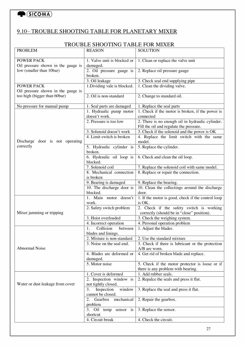
9.10– TROUBLE SHOOTING TABLE FOR PLANETARY MIXER
TROUBLE SHOOTING TABLE FOR MIXER PROBLEM REASON SOLUTION
1. Valve unit is blocked or damaged.
1. Clean or replace the valve unit
2. Oil pressure gauge is broken.
2. Replace oil pressure gauge
POWER PACK Oil pressure shown in the gauge is low (smaller than 10bar)
3. Oil leakage 3. Check seal end supplying pipe 1.Dividing vale is blocked.
1. Clean the dividing valve. POWER PACK Oil pressure shown in the gauge is too high (bigger than 60bar) 2. Oil is non-standard
2. Change to standard oil.
No pressure for manual pump 1. Seal parts are damaged 1. Replace the seal parts 1. Hydraulic pump motor doesn’t work.
1. Check if the motor is broken, if the power is connected
2. Pressure is too low 2. There is no enough oil in hydraulic cylinder. Fill the oil and regulate the pressure.
3. Solenoid doesn’t work 3. Check if the solenoid and the power is OK 4. Limit switch is broken 4. Replace the limit switch with the same
model. 5. Hydraulic cylinder is broken.
5. Replace the cylinder.
6. Hydraulic oil loop is blocked.
6. Check and clean the oil loop.
7. Solenoid coil 7. Replace the solenoid coil with same model. 8. Mechanical connection is broken
8. Replace or repair the connection.
9. Bearing is damaged 9. Replace the bearing.
Discharge door is not operating correctly
10. The discharge door is blocked.
10. Clean the collectings around the discharge door.
1. Main motor doesn’t work.
1. If the motor is good, check if the control loop is OK.
2. Safety switch problem 2. Check if the safety switch is working correctly (should be in “close” position).
3. Hoist overloaded 3. Check the weighing system.
Mixer jamming or tripping
4. Incorrect operation 4. Personal operation problem 1. Collision between blades and linings.
1. Adjust the blades.
2. Mixture is non-standard 2. Use the standard mixture 3. Noise on the seal end. 3. Check if there is lubricant or the protection
A/B are worn. 4. Blades are deformed or damaged.
4. Get rid of broken blade and replace.
Abnormal Noise
5. Motor noise 5. Check if the motor protector is loose or if there is any problem with bearing.
1. Cover is deformed 1. Add rubber seals. 2. Inspection window is not tightly closed.
2. Repalce the seals and press it flat.
3. Inspection window cannot be closed.
3. Replace the seal and press it flat.
2. Gearbox mechanical problem
2. Repair the gearbox.
3. Oil temp sensor is shortcut
3. Replace the sensor.
Water or dust leakage from cover
4. Circuit break 4. Check the circuit.
28
9.11 – MOTOR REPAIR AND MAINTENANCE a. Keep the working environment dry and keep the motor surface clean. Protect the inlet opening
from dust or fiber. b. When the thermal protector and short-circuit protection device act, check if there is something
wrong with the motor or the overloading or protection setting is too low. Clear the problem before operation again.
c. Keep a good lubrication of the motor. Normally, fill or replace the lubricant every 5000 working hours (sealed bearing doesn’t need to replace the lubricant during the whole use life). Replace the lubricant in time when the parts get hot or the grease deteriorates.
d. When the bearing reaches its terminal use time, the motor vibration would be greater and and the noise bigger. Replace the bearing if the radial internal clearance reaches the below data:
Bearing Inner Dia(mm) 10-30 35-50 55-80 85-120 Maximum wear radial internal clearance (mm)
0.1 0.15 0.2 0.3
10) SPARE PARTS MANUAL 10.1 – GENERAL The spare parts manual consists of a series of drawings, listed in the general table, enabling easy and rapid identification of parts. 10.2 – HOW TO ORDER SPARE PARTS To order spare parts, fill in the attached form. Make sure to follow the instructions given there, it is very important to point out: type of machine, serial number and year of manufacturing.
IMPORTANT: To avoid any mistakes, we recommend photocopying the form and sending it to the producer and area representative.
29
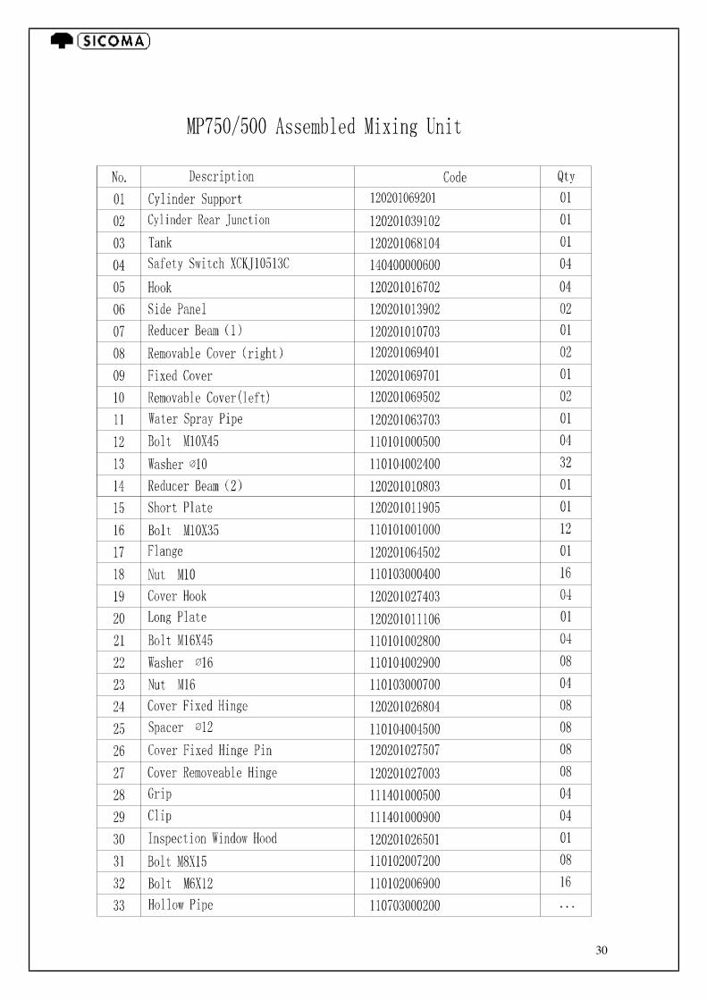
30

31
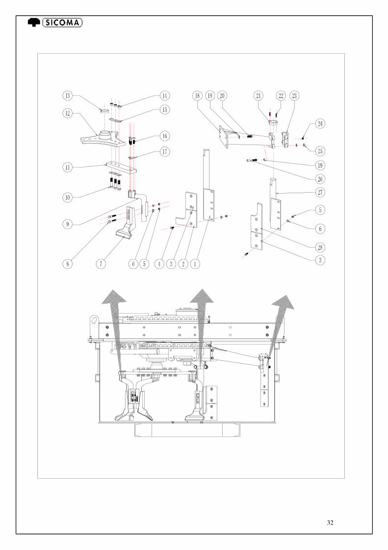
32

33

34
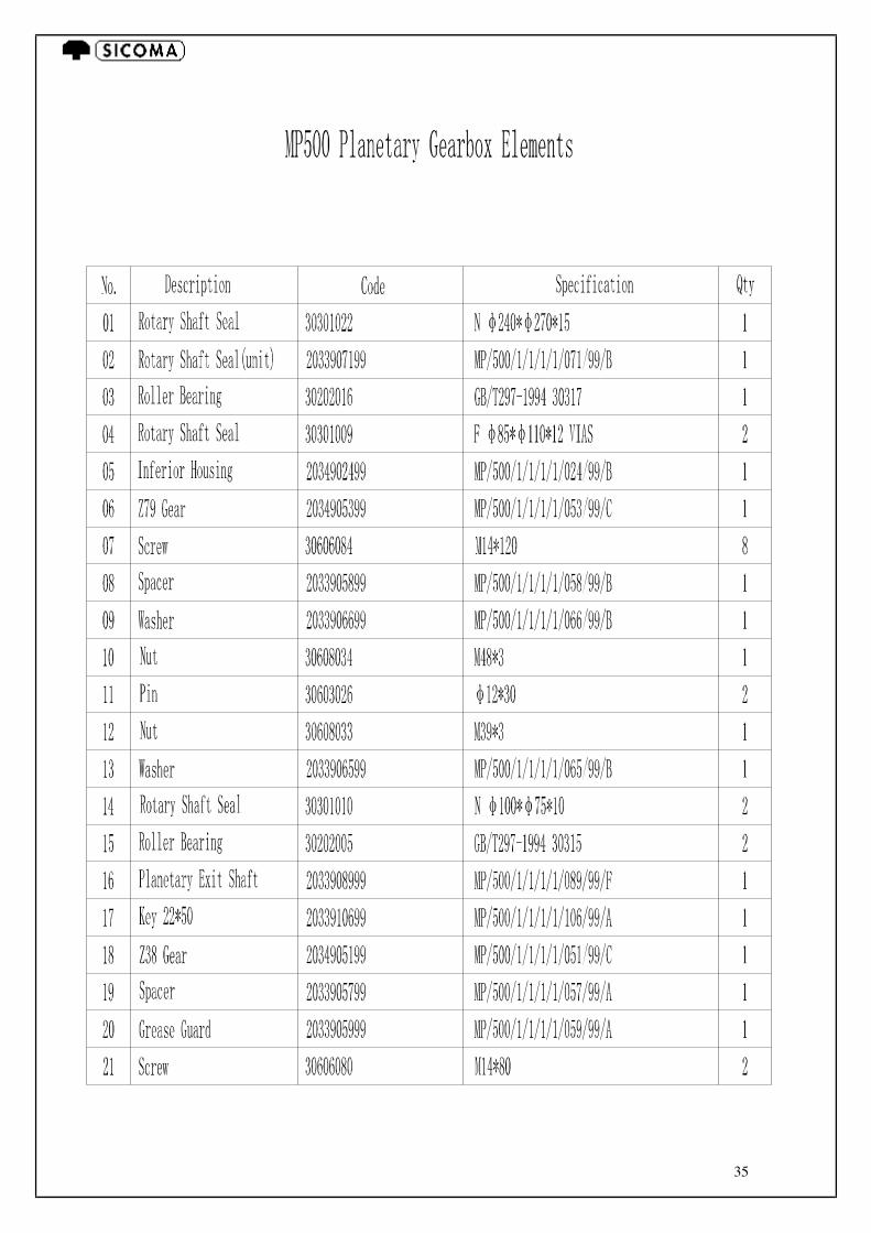
35

36
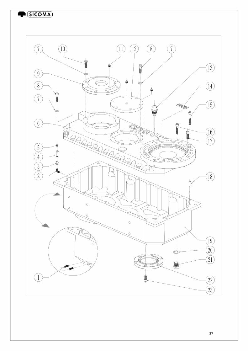
37
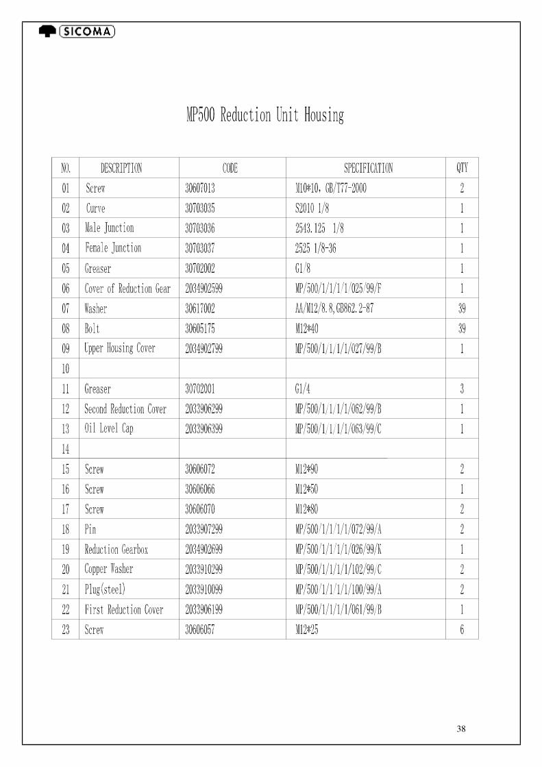
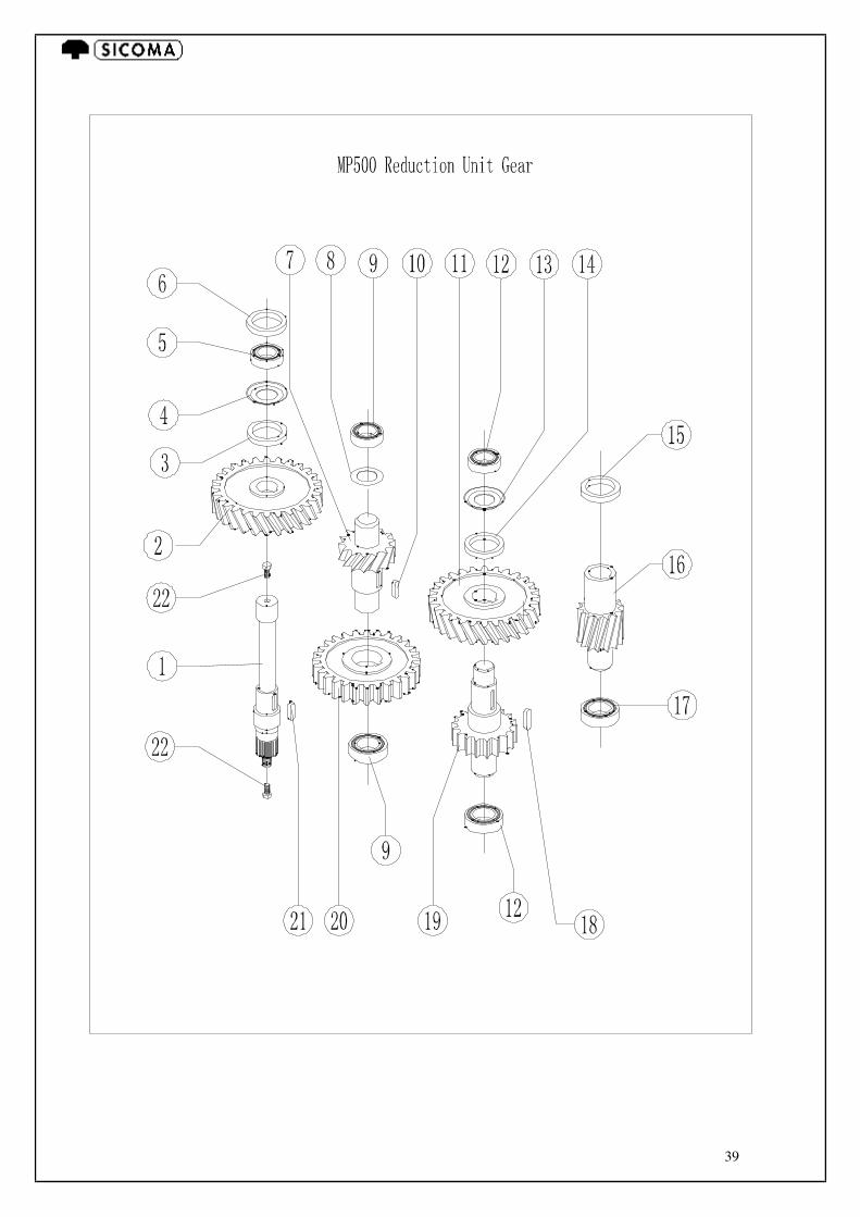
38
39

40
41
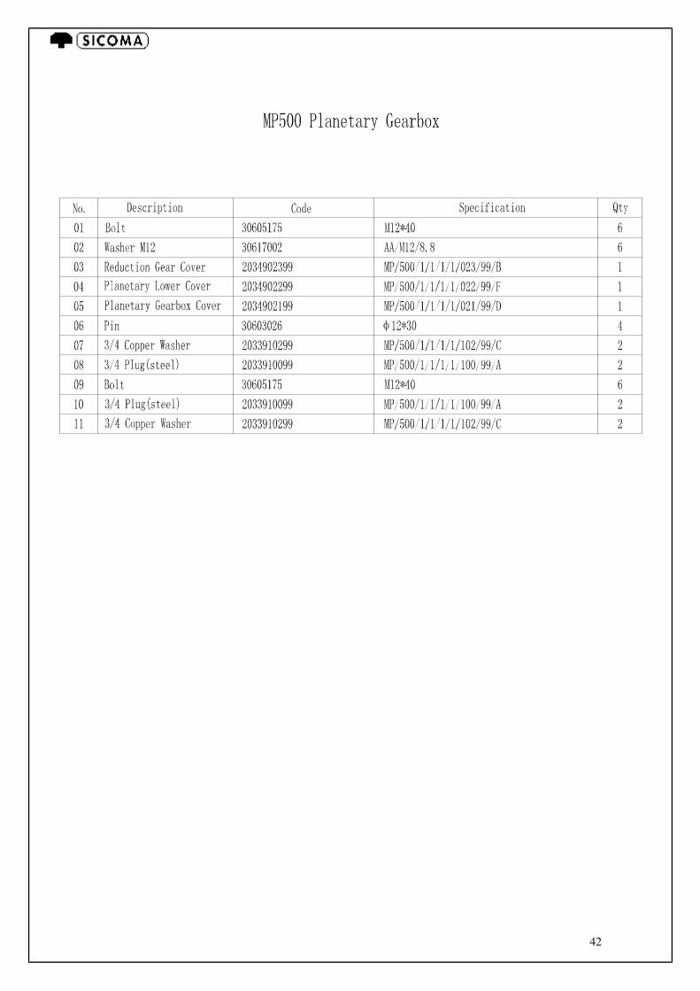
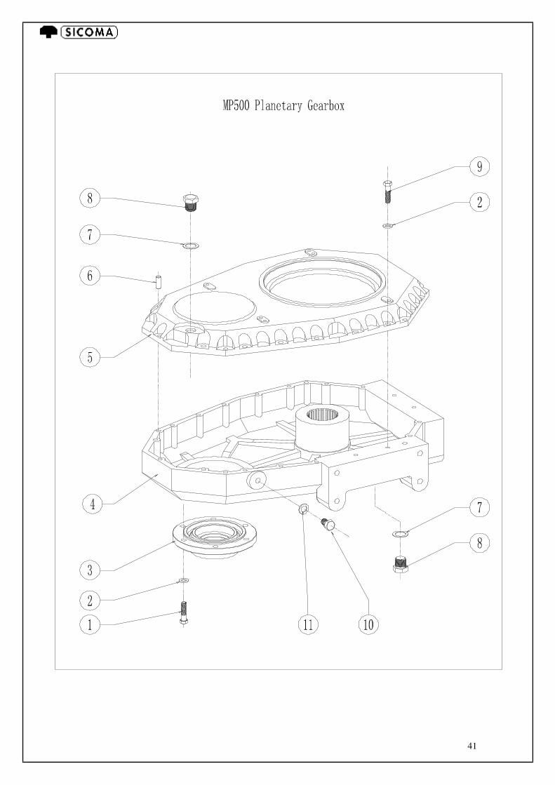
42

43
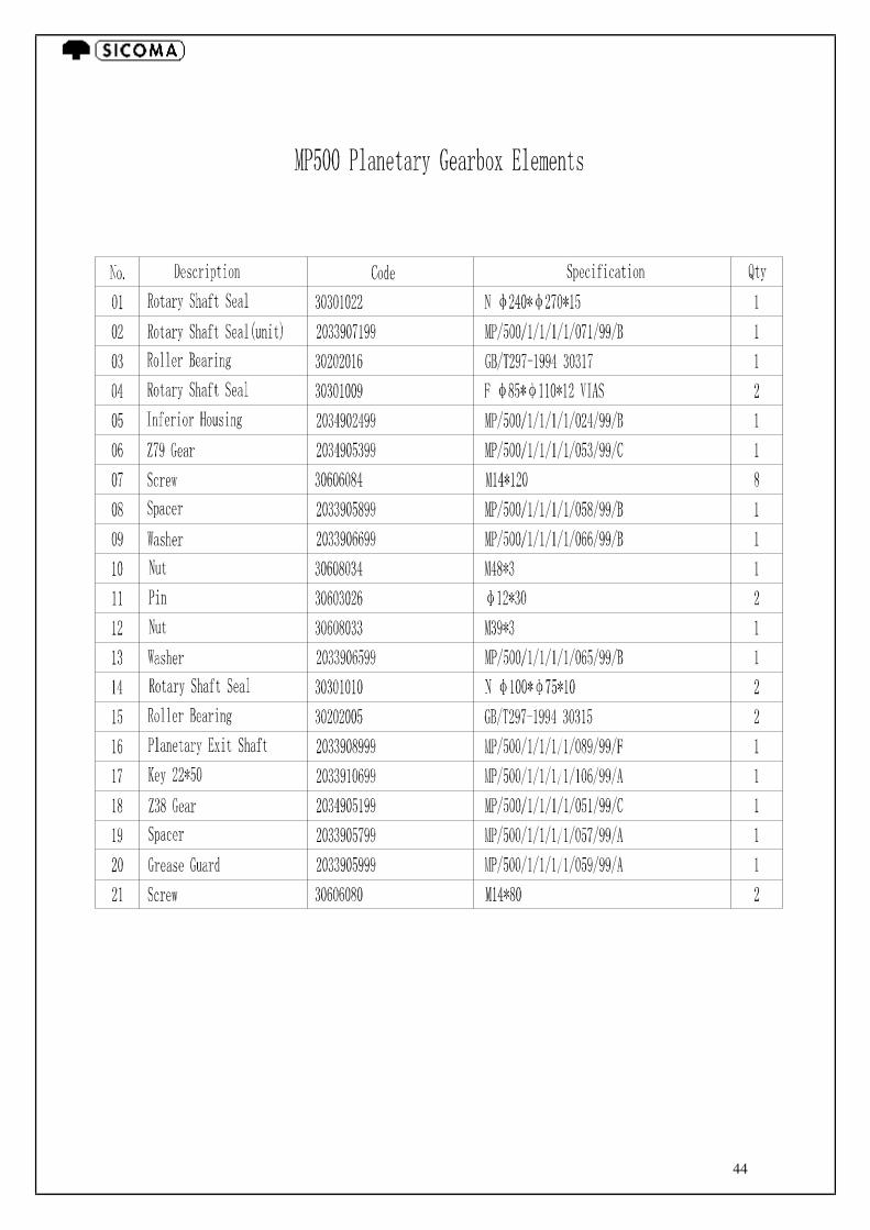
44

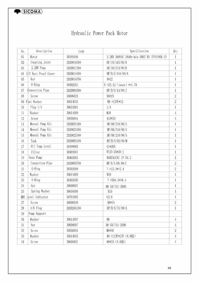
45

46
47
48
49
50
51
SPARE PARTS ORDER FORM
PURCHASER’S ADDRESS: ______________________________ ______________________________________________________ ______________________________________________________ TYPE OF MACHINE: ___________________________________ SERIAL NUMBER: _____________________________________ YEAR OF PRODUCER:_____________________________
LIST OF PARTS TO BE SENT TO THE ABOVE ADDRESS TABLE
No POSIT.
No DRAWING
No DESCRIPTION QUANTITY REQUESTED
Means of delivery: _____________________ __________________ ______________________________ Date Stamp and signature of purchaser