siebreak-vcb™ switchgear...switchgear with fixed-mounted circuit breakers use this selection and...
TRANSCRIPT
usa.siemens.com/SIEBREAK
SIEBREAK-VCB™ switchgearMetal-enclosed interrupter 5 kV-15 kV

SIEBREAK-VCB™ medium-voltage, metal-enclosed interrupter switchgear with fixed-mounted circuit breakers
Use this selection and application guide for:
1. Applications with maximum rated voltage up to 15 kV and continuous current rating up to 1,200 A.
2. Specifying switch-circuit breaker metal-enclosed interrupter switchgear configurations.
3. Specifying single and duplex switch types.
4. Assisting with configuring switch-circuit breaker type for various applications, including standalone, transformer primary, and lineups.
5. Front-access configurations when space is a concern.
6. Protective relay and metering capabilities for your switch-circuit breaker switchgear.
2
SIEBREAK-VCB™ metal-enclosed interrupter switchgear | Selection and application guide
Table of contents
Overview 04 – 05
Construction 06
Technical data 07
Switch-circuit breaker types 08
Application configuration 09 – 18
Floor plans and anchoring 19 – 20
Elevation views 21 – 22
Section views 23
Transformer terminations 24 – 27
Circuit breaker ratings and options 28
Protective relays 29 – 31
Metering 32 – 33
Operation and maintenance arc-flash reduction system (OMARS) 34 – 35
3
Selection and application guide | SIEBREAK-VCB™ metal-enclosed interrupter switchgear

GeneralSiemens SIEBREAK-VCB™ load-interrupter switchgear is a modular assembly of switches, fixed-mounted vacuum circuit breakers, and bus assemblies that are fully integrated both mechanically and electrically to provide the highest level of medium- voltage circuit protection.
Siemens SIEBREAK, part of the metal-enclosed interrupter switchgear family, is a modular design consisting of a switch, fuses, and bus in an assembly that is fully integrated both mechanically and electrically to provide medium-voltage circuit protection. For more information on SIEBREAK, refer to EMMS-T40049-XX-4AUS
Applications:• Standalone bay
• Transformer primary
• Lineups.
Features and benefits:• 5 kV and 15 kV voltage classes
• 600 A and 1,200 A continuous current
• 25 kA and 40 kA fixed-mounted vacuum circuit breaker
• Siemens overcurrent protection relay
• Indoor type 1 enclosure
• Single and duplex switch-circuit breaker types
• Large 8” x 18” (203 mm x 457 mm) viewing window
• Hinged, grounded metal barrier in front of switch blades
• Phase barriers between switch poles
• 11-gauge doors, covers, and barriers
• Silver-plated copper bus
• Provisions for key interlocking
• Mechanical door and switch interlock
• Upper and lower ventilation louvers
• Glass-polyester bus supports
• Non-corrosive nameplate
• Space heater with thermostat
• NEMA CC1 hole patterns for cable termination
• Current transformers (CTs) - one per phase
• Can be intergated into a lineup of SIEBREAK fused load-interrupter switchgear.
Standard outdoor features:• Bottom cover plate
• Externally removable filters
• 6” (152 mm) formed steel base.
Modular configurations to mount:• Surge arresters
• Instrument transformers
• Control power transformers
• Power meters.
Overview
4
SIEBREAK-VCB™ metal-enclosed interrupter switchgear | Selection and application guide
Arc-flash mitigationSuitable for application as a virtual secondary main circuit breaker, to allow reduction in arc-flash incident energy in the low-voltage switchgear for faults on the main bus (with no main circuit breaker) or faults on the line side of a main circuit breaker.
Optional:• UL or C-UL Listing
• Indoor type 2 drip-proof enclosure
• Indoor type 12 dust-resistant enclosure
• Outdoor non-walk-in type 3R enclosure
• High-track resistance bus supports
• Auxiliary switches (2 NO-2 NC)
• Mimic bus
• Ground studs (ball stud) type
• Screens and filters (indoor)
• Tin-plated copper bus
• Second set of CTs.
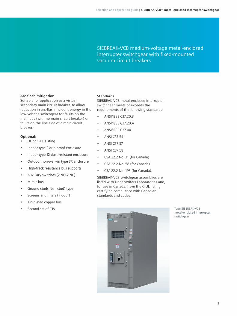
OverviewSIEBREAK-VCB medium-voltage metal-enclosed interrupter switchgear with fixed-mounted vacuum circuit breakers
Type SIEBREAK-VCB metal-enclosed interrupter switchgear
StandardsSIEBREAK-VCB metal-enclosed interrupter switchgear meets or exceeds the requirements of the following standards:
• ANSI/IEEE C37.20.3
• ANSI/IEEE C37.20.4
• ANSI/IEEE C37.04
• ANSI C37.54
• ANSI C37.57
• ANSI C37.58
• CSA 22.2 No. 31 (for Canada)
• CSA 22.2 No. 58 (for Canada)
• CSA 22.2 No. 193 (for Canada).
SIEBREAK-VCB switchgear assemblies are listed with Underwriters Laboratories and, for use in Canada, have the C-UL listing certifying compliance with Canadian standards and codes.
5
Selection and application guide | SIEBREAK-VCB™ metal-enclosed interrupter switchgear

Construction
SIEBREAK-VCB metal-enclosed interrupter switchgear is of metal-enclosed construction as described in ANSI/IEEE standards. The equipment is tested and factory assembled in convenient shipping groups. It is ruggedly constructed of 11-gauge sheet steel including the doors. The assembly employs bolted construction.
SIEBREAK-VCB’s modular design is available in many different enclosure types and bus configurations. The switch mechanism is arranged in the upper portion of the enclosure while the vacuum circuit breaker is located in the lower portion for ease of operation and inspection. A large viewing window is standard for viewing the position of the switch blades while the door is closed. The front door and switch operating mechanism are interlocked to prohibit access to the switch compartment or vacuum circuit breaker when the switch is closed and prohibit operating the switch-operating mechanism when the door is open. The door interlock is mechanical for single switch-circuit breaker arrangements, and key interlocks are used for interlocking duplex switch-circuit breaker arrangements.
Load-interrupter switch Manually-operated, single-throw, gang-operated, stored-energy operated switchIt combines the blades with arc chutes to ensure no arcing occurs on main contacts extending the life of the main blades.
A single upward movement of the operating handle charges the operator and closes the switch, and conversely opens the switch by a downward movement of the handle.
Operating switch handleEquipped with position indicators to show the position of switch as open or closed. Operating spring is discharged in either position.
Viewing windowA large 8” x 18” (203 mm x 457 mm) high-impact viewing window is located and gasketed on the front door for direct line-of-sight viewing of the three switch blades with the door closed.
NameplateNon-corrosive rating nameplate.
Full-height front doorThe front door is equipped with two latching, chrome-plated handles. Handles are available in keyed type to add security. The door is equipped with a door stop.
Door and switch interlockDoor and switch interlock prevents access to the vacuum circuit breaker and switch when the switch is closed and prevents operation of switch handle when the door is open.
Provision for key interlocksOperating mechanism is equipped with provision for key interlocking with remote devices, such as transformer secondary circuit breakers or other switches. Key interlocks can also be provided to prevent closing both switches of a duplex arrangement simultaneously.
DoorsThe doors have stainless-steel door hinges and chrome-plated door fasteners.
Internal barrierThe internal barrier is a grounded, perforated, metal barrier inside the outer door in front of switch to shield against accidental contact.
Provisions for door padlocksThe front door (and rear door, if provided,) is equipped with a hasp for use with purchaser’s padlock.
Steel structureEach section is self-supporting and has 11-gauge steel panels with bolted frame.
VentilationStandard ventilation louvers are located in the top and bottom, front and rear of each section.
Bus barsThe bus bars are copper, silver-plated. Tin-plated is optional.
Ground busGround bus extends across the vertical section.
Type SIEBREAK-VCB metal-enclosed interrupter
switchgear with front door opened
6
SIEBREAK-VCB™ metal-enclosed interrupter switchgear | Selection and application guide

Technical data
SIEBREAK-VCB metal-enclosed interrupter switchgear has been tested under short-circuit conditions in a recognized high-power test laboratory under UL procedures. Tests were performed in accordance with ANSI, IEEE, and CSA standards.
The design tests extend beyond the switch-circuit breaker assembly to also the enclosure assembly, including the venting system and the bus spacing and bracing, as well as mechanical life tests.
SIEBREAK switchgear ratings
System design
voltage kV
Dielectric withstand voltage Main bus1 continuous
current A rms
Short-circuit current Unfused kA sym
Fault-closing current Unfused kA rms
Power frequency kV
rms
Impulse kV peak
5.0 19 60600
1,200 2,000
25 38
39 59
15.0 36 95600
1,200 2,000
25 38
39 59
Footnotes:1. Main bus is not provided on single-unit
arrangements.2. Short-circuit current and closing and latching
current are limited to the capabilities of the load-interrupter switch.
3. Closing and latching current is that of the circuit breaker and is based on the load-interrupter switch being in the CLOSED position.
Type SBVCB vacuum circuit breaker ratings
System design voltage kV
Dielectric withstand voltage
Continuous current A rms
Short-circuit current2 kA sym
Circuit breaker type
Closing and latching current2,3
Asymmetrical (1.55 x I) kA rms
Closing and latching current2,3
Peak (2.60 x I) kA peak
Power frequency
kV rms
Impulse kV peak
4.76 19 60600
1,200
2505-SBVCB-25-0600-6505-SBVCB-25-1200-65
39 65
383 05-SBVCB-40-0600-10405-SBVCB-40-1200-104
65 104
15.0 36 95600
1,200
2515-SBVCB-25-0600-6515-SBVCB-25-1200-65
39 65
383 15-SBVCB-40-0600-10415-SBVCB-40-1200-104
65 104
7
Selection and application guide | SIEBREAK-VCB™ metal-enclosed interrupter switchgear

•
•B
DescriptionSiemens type SIEBREAK-VCB metal-enclosed interrupter switchgear provides a safe, easy-to-use, cost-effective, reliable, and flexible solution for switching and fault protection for medium-voltage circuits rated from 2.4 kV to 15 kV. SIEBREAK-VCB switchgear provides a manually-operated, single-throw, gang-operated switch mechanism with fixed-mounted vacuum circuit breakers where high-duty operations are not needed while offering the characteristics critical for safety and system coordination.
SIEBREAK-VCB is available in two basic switch types:
• Single
• Duplex.
These switch-circuit breaker types are applicable for standalone, transformer primary, and lineup applications.
Single-source applications SingleSingle vertical section equipped with one 600 A or 1,200 A load-interrupter switch rated up to 15 kV with cable incoming-line termination and load-cable termination. SIEBREAK-VCB offers cable direction for incoming and outgoing cable entry for either top or bottom and with an option for close-coupled line or load connection to dry- or liquid-filled type transformer.
Dual-source applications DuplexTwo close-coupled vertical sections each equipped with one 600 A or 1,200 A load-interrupter switch rated up to 15 kV. SIEBREAK-VCB offers incoming and outgoing cable direction for either top or bottom cable entry with an option for close-coupled load connection to dry- or liquid-filled type transformer.
Switch-circuit breaker typesA cost-effective alternative when high and medium duty-cycle operations are needed
Item Description
A600 A or 1,200 A interrupter switch
BFixed-mounted vacuum circuit
breaker
Single
A
Duplex
AA
•
•B
8
SIEBREAK-VCB™ metal-enclosed interrupter switchgear | Selection and application guide

Application configurationSiemens SIEBREAK-VCB switchgear is a complete product line used in medium-voltage applications:
• Standalone
• Transformer primary
• Lineups (i.e., main-tie-main, main- feeders, automatic-transfer).
Standalone bay
Standalone bay - singleSingle freestanding switch-circuit breaker section with dimensions and weights shown in the table to the right. Ideal for an application where single-supply source is required for one outgoing feeder (usually not close-coupled to a transformer) for an industrial power user.
Application configurationStandalone, transformer primary, and lineups
Standalone - single - estimated dimensions and weight in in. (mm) or lbs (kg)
Maximum design
voltage kV
Enclosure type
Continuous current A
Depth Width Height Weight
5.0 Indoor 600 72 (1,829) 36 (914) 92 (2,337) 2,350 (1,066)
5.0 Indoor 1,200 72 (1,829) 36 (914) 92 (2,337) 2,500 (1,134)
5.0 Outdoor 600 72 (1,829) 36 (914) 105 (2,667) 2,950 (1,338)
5.0 Outdoor 1,200 72 (1,829) 36 (914) 105 (2,667) 3,100 (1,406)
15.0 Indoor 600 72 (1,829) 36 (914) 92 (2,337) 2,350 (1,066)
15.0 Indoor 1,200 72 (1,829) 36 (914) 92 (2,337) 2,500 (1,134)
15.0 Outdoor 600 72 (1,829) 36 (914) 105 (2,667) 2,950 (1,338)
15.0 Outdoor 1,200 72 (1,829) 36 (914) 105 (2,667) 3,100 (1,406)
Footnotes:1. Line and load cables may be top or bottom entry.2. Optional distribution, intermediate, or station surge arresters.3. Optional voltage transformers, and metering. Consult factory.4. Optional control power transformers. Consult factory.5. Reference the floor plan on pages 19-20, elevation views on pages 21-22, section
views on page 23, and transformer terminations on pages 24-27 when applicable.
Item Description
A 600 A or 1,200 A interrupter switch
B Fixed-mounted vacuum circuit breaker
Bottom-entry incoming and
outgoing
A
Top-entry incoming and
outgoing
A
•
•B
•
•B
9
Selection and application guide | SIEBREAK-VCB™ metal-enclosed interrupter switchgear

•
•B
•
•B
Standalone bay - duplexTwo close-coupled freestanding switch-circuit breaker sections with dimensions and weights shown in the table below. Ideal for an application where dual-supply source is required for one outgoing feeder (not close-coupled to a transformer) for an industrial power user.
Standalone - duplex - estimated dimensions and weight in in. (mm) or lbs (kg)
Maximum design
voltage kV
Enclosure type
Continuous current A
Depth Width Height Weight
5.0 Indoor 600 72 (1,829) 72 (1,829) 92 (2,337) 3,450 (1,565)
5.0 Indoor 1,200 72 (1,829) 72 (1,829) 92 (2,337) 3,600 (1,633)
5.0 Outdoor 600 72 (1,829) 72 (1,829) 105 (2,667) 4,050 (1,837)
5.0 Outdoor 1,200 72 (1,829) 72 (1,829) 105 (2,667) 4,200 (1,905)
15.0 Indoor 600 72 (1,829) 72 (1,829) 92 (2,337) 3,450 (1,565)
15.0 Indoor 1,200 72 (1,829) 72 (1,829) 92 (2,337) 3,600 (1,633)
15.0 Outdoor 600 72 (1,829) 72 (1,829) 105 (2,667) 4,050 (1,837)
15.0 Outdoor 1,200 72 (1,829) 72 (1,829) 105 (2,667) 4,200 (1,905)
Footnotes:1. Line and load cables may be top or bottom entry.2. Optional distribution, intermediate, or station surge arresters.3. Optional voltage transformers and metering. 4. Optional control power transformers - load connected and located in the non-circuit
breaker section of the two sections.
Item Description
A 600 A or 1,200 A interrupter switch
B Fixed-mounted vacuum circuit breaker
Bottom-entry incoming and
outgoing
Top-entry incoming and
outgoing
AA
AA
10
SIEBREAK-VCB™ metal-enclosed interrupter switchgear | Selection and application guide

Transformer primaryCable terminations provided for incoming line. The load termination is a close-coupled connection to a transformer primary.
Transformer primary - single - estimated dimensions and weight in in. (mm) or lbs (kg)
Maximum design
voltage kV
Enclosure type
Transformer type
Continuous current A
Depth Width Height Weight
5.0 Indoor Dry 600 72 (1,829)) 36 (914) 92 (2,337) 2,350 (1,066)
5.0 Indoor Dry 1,200 72 (1,829) 36 (914) 92 (2,337) 2,500 (1,134)
5.0 Indoor Liquid-filled 600 72 (1,829) 54 (1,372) 92 (2,337) 2,800 (1,260)
5.0 Indoor Liquid-filled 1,200 72 (1,829) 54 (1,372) 92 (2,337) 2,950 (1,338)
5.0 Outdoor Dry 600 72 (1,829) 38 (965) 105 (2,667) 2,950 (1,338)
5.0 Outdoor Dry 1,200 72 (1,829) 38 (965) 105 (2,667) 3,100 (1,406)
5.0 Outdoor Liquid-filled 600 72 (1,829) 54 (1,372) 105 (2,667) 3,400 (1,542)
5.0 Outdoor Liquid-filled 1,200 72 (1,829) 54 (1,372) 105 (2,667) 3,550 (1,610)
15.0 Indoor Dry 600 72 (1,829) 36 (914) 92 (2,337) 2,350 (1,066)
15.0 Indoor Dry 1,200 72 (1,829) 36 (914) 92 (2,337) 2,500 (1,134)
15.0 Indoor Liquid-filled 600 72 (1,829) 54 (1,372) 92 (2,337) 2,800 (1,260)
15.0 Indoor Liquid-filled 1,200 72 (1,829) 54 (1,372) 92 (2,337) 2,950 (1,338)
15.0 Outdoor Dry 600 72 (1,829) 38 (965) 105 (2,667) 2,950 (1,338)
15.0 Outdoor Dry 1,200 72 (1,829) 38 (965) 105 (2,667) 3,100 (1,406)
15.0 Outdoor Liquid-filled 600 72 (1,829) 54 (1,372) 105 (2,667) 3,400 (1,542)
15.0 Outdoor Liquid-filled 1,200 72 (1,829) 54 (1,372) 105 (2,667) 3,550 (1,610)
Footnotes:1. Optional distribution,
intermediate, or station surge arresters for incoming-line terminations.
2. Left- or right-side, dry- or liquid-filled type transformers are available.
3. Liquid-filled and outdoor dry-type connection to be throat-type connection.
4. Optional voltage transformers and metering. Refer to pages 30-33 for details.
5. Optional control power transformer. Consult factory for depth requirements.
Transformer primary - singleSingle switch-circuit breaker section with dimensions and weights shown in the table below. Ideal for single-source applications with outgoing close-coupled connection to the primary side of a dry or liquid-filled transformer for a low-voltage or medium-voltage substation.
Item Description
A600 A or 1,200 A interrupter switch
BFixed-mounted vacuum circuit
breaker
Bottom-entry incoming and right-hand side
dry transformer
A
Top-entry incoming and right-hand side
dry transformer
A A A
A A A
Bottom-entry incoming and left-hand side
dry transformer
Top-entry incoming and left-hand side
dry transformer
Bottom-entry incoming and right-hand side liquid transformer
Top-entry incoming and right-hand side liquid transformer
Bottom-entry incoming and left-hand side liquid transformer
Top-entry incoming and left-hand side liquid transformer
A
•
•B
•
•B
•
•B
•
•B
•
•B
•
•B
•
•B
•
•B
11
Selection and application guide | SIEBREAK-VCB™ metal-enclosed interrupter switchgear

•
•B
•
•B
•
•B
Transformer primary - duplexTwo load-interrupter switch sections connected to one set of fuses with dimensions and weights shown in the table below. Ideal for dual-supply source applications for an outgoing, close-coupled connection to a primary side of a dry or liquid-filled transformer for a low-voltage or medium-voltage substation.
Footnotes:1. Optional distribution,
intermediate, or station surge arresters for incoming-line terminations.
2. Left- or right-side, dry- or liquid-filled type transformers are available.
3. Liquid-filled and outdoor dry-type connection to be throat-type connection.
4. Optional voltage transformers and metering. Refer to pages 30-33 for details.
5. Optional control power transformer. Consult factory for depth requirements.
Item Description
A600 A or 1,200 A interrupter switch
BFixed-mounted vacuum circuit
breaker
Transformer primary - duplex - estimated dimensions and weight in in. (mm) or lbs (kg)
Maximum design
voltage kV
Enclosure type
Transformer type
Continuous current A
Depth Width Height Weight
5.0 Indoor Dry 600 72 (1,829) 72 (1,829) 92 (2,337) 3,750 (1,701)
5.0 Indoor Dry 1,200 72 (1,829) 72 (1,829) 92 (2,337) 3,900 (1,769)
5.0 Indoor Liquid-filled 600 72 (1,829) 90 (2,286) 92 (2,337) 4,200 (1,905)
5.0 Indoor Liquid-filled 1,200 72 (1,829) 90 (2,286) 92 (2,337) 4,350 (1,973)
5.0 Outdoor Dry 600 72 (1,829) 75 (1,905) 105 (2,667) 4,350 (1,973)
5.0 Outdoor Dry 1,200 72 (1,829) 75 (1,905) 105 (2,667) 4,500 (2,041)
5.0 Outdoor Liquid-filled 600 72 (1,829) 90 (2,286) 105 (2,667) 4,800 (2,177)
5.0 Outdoor Liquid-filled 1,200 72 (1,829) 90 (2,286) 105 (2,667) 4,950 (2,245)
15.0 Indoor Dry 600 72 (1,829) 72 (1,829) 92 (2,337) 3,750 (1,701)
15.0 Indoor Dry 1,200 72 (1,829) 72 (1,829) 92 (2,337) 3,900 (1,769)
15.0 Indoor Liquid-filled 600 72 (1,829) 90 (2,286) 92 (2,337) 4,200 (1,905)
15.0 Indoor Liquid-filled 1,200 72 (1,829) 90 (2,286) 92 (2,337) 4,350 (1,973)
15.0 Outdoor Dry 600 72 (1,829) 75 (1,905) 105 (2,667) 4,350 (1,973)
15.0 Outdoor Dry 1,200 72 (1,829) 75 (1,905) 105 (2,667) 4,500 (2,041)
15.0 Outdoor Liquid-filled 600 72 (1,829) 90 (2,286) 105 (2,667) 4,800 (2,177)
15.0 Outdoor Liquid-filled 1,200 72 (1,829) 90 (2,286) 105 (2,667) 4,950 (2,245)
Bottom-entry incoming and left-hand side
dry transformer
Top-entry incoming and left-hand side
dry transformer
Bottom-entry incoming and left-hand side liquid transformer
Top-entry incoming and left-hand side liquid transformer
Top-entry incoming and right-hand side
dry transformer
Bottom-entry incoming and right-hand side
dry transformer
AA
Bottom-entry incoming and right-hand side liquid transformer
Top-entry incoming and right-hand side liquid transformer
AA A A A A
•
•B
AAAA A A A A
•
•B
•
•B
•
•B
•
•B
12
SIEBREAK-VCB™ metal-enclosed interrupter switchgear | Selection and application guide

LineupsMultiple vertical sections close-coupled and bus-connected together into a lineup configuration with one or more supply sources characterize lineup configuration types. SIEBREAK-VCB switchgear is available in the lineup configuration for section types including main, tie, and branch feeders. These section types are limited to the single-switch type (duplex not available in a lineup) with main cross bus bars located in the top of the enclosure. Three section types are main, branch feeder, and tie.
Lineups - main incomer - estimated dimensions and weight in in. (mm) or lbs (kg)
Maximum design
voltage kV
Enclosure type
Continuous current A
Depth Width Height Weight
5.0 Indoor 600 72 (1,829) 54 (1,372) 92 (2,337) 3,000 (1,361)
5.0 Indoor 1,200 72 (1,829) 54 (1,372) 92 (2,337) 3,150 (1,429)
5.0 Outdoor 600 72 (1,829) 54 (1,372) 105 (2,667) 3,600 (1,633)
5.0 Outdoor 1,200 72 (1,829) 54 (1,372) 105 (2,667) 3,750 (1,701)
15.0 Indoor 600 72 (1,829) 54 (1,372) 92 (2,337) 3,000 (1,361)
15.0 Indoor 1,200 72 (1,829) 54 (1,372) 92 (2,337) 3,150 (1,429)
15.0 Outdoor 600 72 (1,829) 54 (1,372) 105 (2,667) 3,600 (1,633)
15.0 Outdoor 1,200 72 (1,829) 54 (1,372) 105 (2,667) 3,750 (1,701)
Footnotes:1. Optional distribution,
intermediate, or station surge arresters for incoming-line terminations.
2. Optional voltage transformers, for both incoming-line terminations.
3. Optional low-voltage compartment power metering.
4. Optional control power transformer. Consult factory for depth requirement.
Item Description
A600 A or 1,200 A interrupter switch
BFixed-mounted vacuum circuit
breaker
Lineups - main incomerOne vertical section is equipped with a 600 A or 1,200 A load-interrupter switch and one 18 in. (457 mm) bus transition section. The incoming-line cable termination is available for either top or bottom entry. Outgoing termination will be a close-coupled load connection with either left- or right-side transition to an adjacent vertical section of SIEBREAK-VCB branch feeders and tie panels.
Bottom-entry incoming and right-hand side
transition
Top-entry incoming and right-hand side
transition
Top-entry incoming and left-hand side
transition
A AA
Bottom-entry incoming and left-hand side
transition
A
Bottom-entry incoming and right-hand side transition and lower
through bus, such as to a tie switch
Top-entry incoming and right-hand side transition and lower
through bus, such as to a tie switch
Top-entry incoming and left-hand side
transition and lower through bus, such as to
a tie switch
A AA
Bottom-entry incoming and left-hand side
transition and lower through bus, such as to
a tie switch
A
•
•B
•
•B
•
•B
•
•B
•
•B
•
•B
•
•B
•
•B
13
Selection and application guide | SIEBREAK-VCB™ metal-enclosed interrupter switchgear
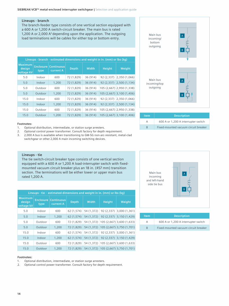
Lineups - branch The branch-feeder type consists of one vertical section equipped with a 600 A or 1,200 A switch-circuit breaker. The main bus is rated 1,200 A or 2,000 A3 depending upon the application. The outgoing load terminations will be cables for either top or bottom entry.
Lineups - branch - estimated dimensions and weight in in. (mm) or lbs (kg)
Maximum design
voltage kV
Enclosure type
Continuous current A
Depth Width Height Weight
5.0 Indoor 600 72 (1,829) 36 (914) 92 (2,337) 2,350 (1,066)
5.0 Indoor 1,200 72 (1,829) 36 (914) 92 (2,337) 2,500 (1,134)
5.0 Outdoor 600 72 (1,829) 36 (914) 105 (2,667) 2,950 (1,338)
5.0 Outdoor 1,200 72 (1,829) 36 (914) 105 (2,667) 3,100 (1,406)
15.0 Indoor 600 72 (1,829) 36 (914) 92 (2,337) 2,350 (1,066)
15.0 Indoor 1,200 72 (1,829) 36 (914) 92 (2,337) 2,500 (1,134)
15.0 Outdoor 600 72 (1,829) 36 (914) 105 (2,667) 2,950 (1,338)
15.0 Outdoor 1,200 72 (1,829) 36 (914) 105 (2,667) 3,100 (1,406)
Footnotes:1. Optional distribution, intermediate, or station surge arresters.2. Optional control power transformer. Consult factory for depth requirement.3. 2,000 A bus is available when transitioning to GM-SG non-arc-resistant, metal-clad
switchgear or other 2,000 A main incoming switching devices.
Lineups - tie The tie switch-circuit breaker type consists of one vertical section equipped with a 600 A or 1,200 A load-interrupter switch with fixed-mounted vacuum circuit breaker plus an 18 in. (457 mm) transition section. The terminations will be either lower or upper main bus rated 1,200 A.
Lineups - tie - estimated dimensions and weight in in. (mm) or lbs (kg)
Maximum design
voltage kV
Enclosure type
Continuous current A
Depth Width Height Weight
5.0 Indoor 600 62 (1,574) 54 (1,372) 92 (2,337) 3,000 (1,361)
5.0 Indoor 1,200 62 (1,574) 54 (1,372) 92 (2,337) 3,150 (1,429)
5.0 Outdoor 600 72 (1,829) 54 (1,372) 105 (2,667) 3,600 (1,633)
5.0 Outdoor 1,200 72 (1,829) 54 (1,372) 105 (2,667) 3,750 (1,701)
15.0 Indoor 600 62 (1,574) 54 (1,372) 92 (2,337) 3,000 (1,361)
15.0 Indoor 1,200 62 (1,574) 54 (1,372) 92 (2,337) 3,150 (1,429)
15.0 Outdoor 600 72 (1,829) 54 (1,372) 105 (2,667) 3,600 (1,633)
15.0 Outdoor 1,200 72 (1,829) 54 (1,372) 105 (2,667) 3,750 (1,701)
Footnotes:1. Optional distribution, intermediate, or station surge arresters.2. Optional control power transformer. Consult factory for depth requirement.
Main bus incoming/
bottom outgoing
Item Description
A 600 A or 1,200 A interrupter switch
B Fixed-mounted vacuum circuit breaker
Main bus incoming/top
outgoing
Item Description
A 600 A or 1,200 A interrupter switch
B Fixed-mounted vacuum circuit breaker
A
A
Main bus incoming
and left-hand side tie bus
A
•
•B
•
•B
•
•B
14
SIEBREAK-VCB™ metal-enclosed interrupter switchgear | Selection and application guide

Lineup configurationsItem Description
A 600 A or 1,200 A interrupter switch
B Fixed-mounted vacuum circuit breaker
Main-tie-mainThis configuration consists of main, tie, and branch feeder switch-circuit breaker types to provide a multi-source solution. It is also equipped with main cross bus up to 1,200 A.
Bottom-entry incoming and left-hand side transition and
lower through bus
Main bus incoming/bottom or
top outgoing
Main bus incoming/bottom or
top outgoing
Bottom-entry incoming and
right-hand side transition and
lower through bus
Main bus incoming/bottom or
top outgoing
Main bus incoming/bottom or
top outgoing
Main bus incoming
and left-hand side tie bus
AAA A AAA
Item Description
A 600 A or 1,200 A interrupter switch
B Fixed-mounted vacuum circuit breaker
Main feederThis configuration consists of main and branch feeder switch-circuit breaker types. It is also equipped with main cross bus up to 1,200 A.
Bottom-entry incoming and
right-hand side transition and
lower through bus
Main bus top/bottom
or top outgoing
Main bus top/bottom
or top outgoing
A AA
•
•B
•
•B
•
•B
•
•B
•
•B
•
•B
•
•B
•
•B
•
•B
•
•B
15
Selection and application guide | SIEBREAK-VCB™ metal-enclosed interrupter switchgear

Front-access configurationsSIEBREAK-VCB front-access design offers a space-savings option enabling the user to install the rear of the switchgear near a wall in an electrical room or power equipment center. The front-access design is available in single switch type (not available for duplex) and available as a lineup for the single-switch type (not for duplex).
StandaloneAll cable terminations for both incoming-line and outgoing-load terminations characterize the standalone configuration type.
Footnotes:1. Optional distribution, intermediate, or station
surge arresters.2. Outdoor enclosure not available for front
access.3. Consult factory for auxiliary devices (i.e., CPT,
VTs).
Item Description
A 600 A interrupter switch
B Fixed-mounted vacuum circuit breaker
E Cable-pull section
Single - transformer primary - front access Single switch-circuit breaker panel with dimensions and weights shown in the table below. Suited for single-source applications with outgoing close-coupled connection to primary side of a dry or liquid-filled transformer for a low-voltage or medium-voltage substation.
Single - transformer primary - front access - estimated dimensions and weight in in. (mm) or lbs (kg)
Maximum design
voltage kV
Enclosure type
Transformer type
Continuous current A
Depth Width Height Weight
5.0 Indoor Dry 600 56 (1,422) 60 (1,524) 92 (2,337) 2,700 (1,225)
5.0 Indoor Dry 1,200 56 (1,422) 60 (1,524) 92 (2,337) 2,850 (1,293)
5.0 Indoor Liquid-filled 600 56 (1,422) 78 (1,981) 92 (2,337) 3,150 (1,429)
5.0 Indoor Liquid-filled 1,200 56 (1,422) 78 (1,981) 92 (2,337) 3,300 (1,497)
15.0 Indoor Dry 600 56 (1,422) 60 (1,524) 92 (2,337) 2,700 (1,225)
15.0 Indoor Dry 1,200 56 (1,422) 60 (1,524) 92 (2,337) 2,850 (1,293)
15.0 Indoor Liquid-filled 600 56 (1,422) 78 (1,981) 92 (2,337) 3,150 (1,429)
15.0 Indoor Liquid-filled 1,200 56 (1,422) 78 (1,981) 92 (2,337) 3,300 (1,497)
Footnotes:1. Optional distribution,
intermediate, or station surge arresters.
2. Outdoor enclosure not available for front access.
3. Consult factory for auxiliary devices (i.e., CPT, VTs).
Item Description
A1,200 A interrupter
switch
BFixed-mounted vacuum circuit
breaker
E Cable-pull section
Single - front accessSingle freestanding switch-circuit breaker panel and cable-pull section with dimensions and weights shown in the table below. Ideal for tight spaces for a single-supply source for one outgoing feeder (not close coupled to a transformer) for an industrial power user.
Single - front access - estimated dimensions and weight in in. (mm) or lbs (kg)
Maximum design
voltage kV
Enclosure type
Continuous current A
Depth Width Height Weight
5.0 Indoor 600 56 (1,422) 60 (1,524) 92 (2,337) 2,800 (1,270)
5.0 Indoor 1,200 56 (1,422) 60 (1,524) 92 (2,337) 2,950 (1,338)
15.0 Indoor 600 56 (1,422) 60 (1,524) 92 (2,337) 2,800 (1,270)
15.0 Indoor 1,200 56 (1,422) 60 (1,524) 92 (2,337) 2,950 (1,338)
A A
A
Top-entry incoming and
outgoing
Bottom-entry incoming and
outgoing
EE
A
EE
Top-entry incoming and
right- or left-hand (reverse) side
liquid transformer
Bottom-entry incoming and
right- or left-hand (reverse) side dry
transformer
•
•B
•
•B
•
•B
•
•B
16
SIEBREAK-VCB™ metal-enclosed interrupter switchgear | Selection and application guide

Lineups - front accessMultiple vertical sections close-coupled and bus-connected together into a lineup configuration with one or more supply sources characterize lineup configuration types. SIEBREAK-VCB switchgear is available in the lineup configuration for section types including main, tie, and branch feeders. These section types are limited to the single switch-circuit breaker type (duplex not available in a lineup) with main cross bus bars located in the top of the enclosure.
Lineups - main incomer - front accessA lineup consists of a vertical section is equipped with a 600 A or 1,200 A switch-circuit breaker, an incoming cable-pull section, and one 18 in. (457 mm) bus transition section. The incoming-line cable termination is available for either top or bottom entry. Outgoing termination will be close-coupled load connection either left- or right-side transition to an adjacent vertical section of front-access SIEBREAK-VCB branch feeders and tie panel.
Lineups - main incomer front access - estimated dimensions and weight in in. (mm) or lbs (kg)
Maximum design
voltage kV
Enclosure type
Continuous current A
Depth Width Height Weight
5.0 Indoor 600 56 (1,422) 78 (1,981) 92 (2,337) 3,250 (1,474)
5.0 Indoor 1,200 56 (1,422) 78 (1,981) 92 (2,337) 3,400 (1,542)
15.0 Indoor 600 56 (1,422) 78 (1,981) 92 (2,337) 3,250 (1,474)
15.0 Indoor 1,200 56 (1,422) 78 (1,981) 92 (2,337) 3,400 (1,542)
Lineups - branch - front access The branch-feeder type consists of one vertical section equipped with a 600 A or 1,200 A switch-circuit breaker. The incoming will be main bus rated 1,200 A or 2,000 A4 depending upon the application. The outgoing load terminations will be cables for either top or bottom entry.
Lineups - branch - estimated dimensions and weight in in. (mm) or lbs (kg)
Maximum design
voltage kV
Enclosure type
Continuous current A
Depth Width Height Weight
5.0 Indoor 600 56 (1,422) 60 (1,524) 92 (2,337) 2,800 (1,270)
5.0 Indoor 1,200 56 (1,422) 60 (1,524) 92 (2,337) 2,950 (1,338)
15.0 Indoor 600 56 (1,422) 60 (1,524) 92 (2,337) 2,800 (1,270)
15.0 Indoor 1,200 56 (1,422) 60 (1,524) 92 (2,337) 2,950 (1,338)
Footnotes:1. Optional distribution, intermediate, or station surge arresters.2. Outdoor enclosure not available for front access.3. Consult factory for auxiliary devices (i.e., CPT, VTs). 4. 2,000 A bus is available when transitioning to GM-SG non-arc-resistant, metal-clad
switchgear.
Footnotes:1. Optional distribution, intermediate, or station
surge arresters.2. Outdoor enclosure not available for front
access.3. Consult factory for auxiliary devices (i.e., CPT,
VTs).
Item Description
A 600 A or 1,200 A interrupter switch
B Fixed-mounted vacuum circuit breaker
E Cable-pull section
A
Bottom-entry
incoming in pull section and right-hand side transition
A
Top-entry incoming in pull section and right-hand side transition
Main bus incoming/
bottom outgoing
Item Description
A 600 A or 1,200 A interrupter switch
B Fixed-mounted vacuum circuit breaker
A
E
E
•
•B
•
•B
•
•B
17
Selection and application guide | SIEBREAK-VCB™ metal-enclosed interrupter switchgear
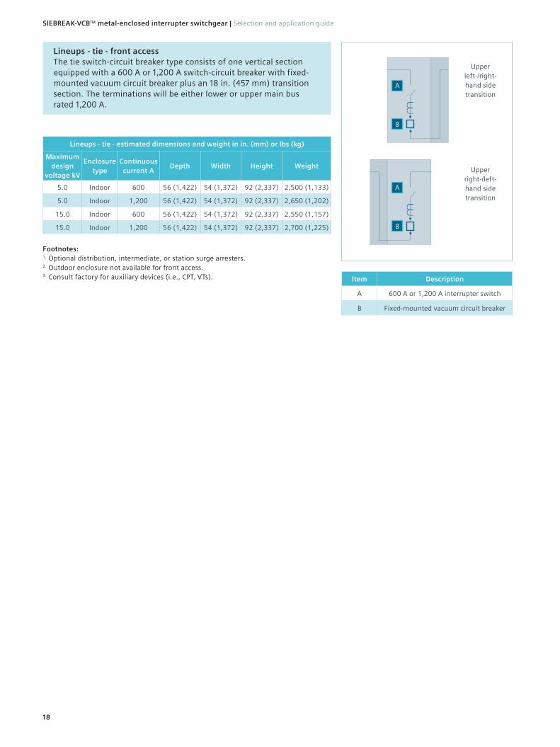
Lineups - tie - front access The tie switch-circuit breaker type consists of one vertical section equipped with a 600 A or 1,200 A switch-circuit breaker with fixed-mounted vacuum circuit breaker plus an 18 in. (457 mm) transition section. The terminations will be either lower or upper main bus rated 1,200 A.
Lineups - tie - estimated dimensions and weight in in. (mm) or lbs (kg)
Maximum design
voltage kV
Enclosure type
Continuous current A
Depth Width Height Weight
5.0 Indoor 600 56 (1,422) 54 (1,372) 92 (2,337) 2,500 (1,133)
5.0 Indoor 1,200 56 (1,422) 54 (1,372) 92 (2,337) 2,650 (1,202)
15.0 Indoor 600 56 (1,422) 54 (1,372) 92 (2,337) 2,550 (1,157)
15.0 Indoor 1,200 56 (1,422) 54 (1,372) 92 (2,337) 2,700 (1,225)
Footnotes:1. Optional distribution, intermediate, or station surge arresters.2. Outdoor enclosure not available for front access.3. Consult factory for auxiliary devices (i.e., CPT, VTs). Item Description
A 600 A or 1,200 A interrupter switch
B Fixed-mounted vacuum circuit breaker
A
A
Upper left-/right- hand side transition
Upper right-/left-hand side transition
•
•B
•
•B
18
SIEBREAK-VCB™ metal-enclosed interrupter switchgear | Selection and application guide
19
Selection and application guide | SIEBREAK-VCB™ metal-enclosed interrupter switchgear
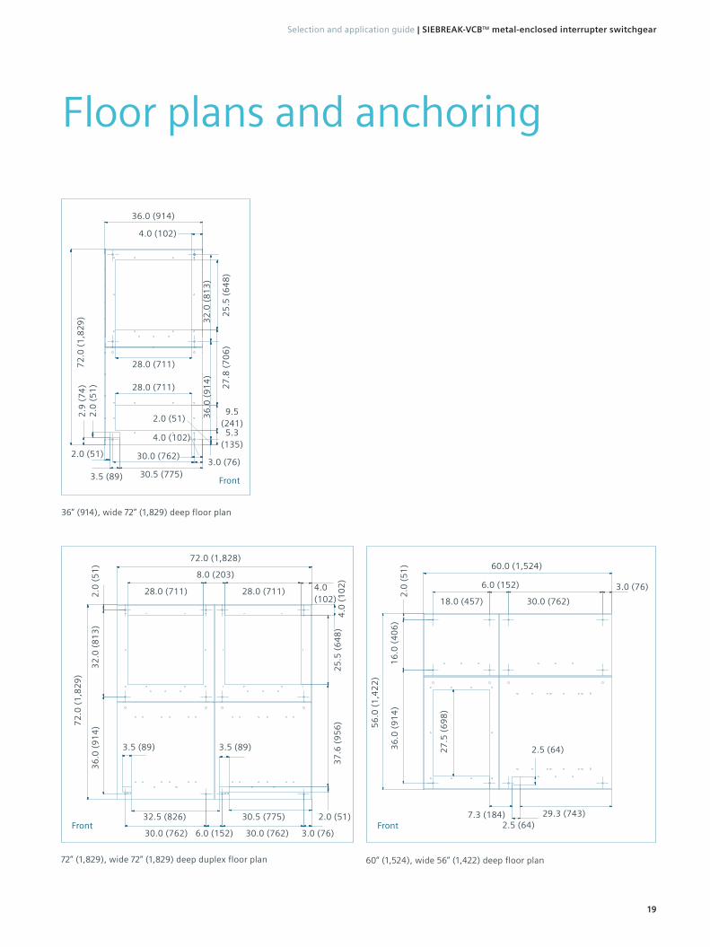
Floor plans and anchoring
72” (1,829), wide 72” (1,829) deep duplex floor plan
30.0 (762)
72.0 (1,828)
3.5 (89)
2.0 (51)
36
.0 (
91
4)
37
.6 (
95
6) 72
.0 (
1,8
29
)
25
.5 (
64
8)
2.0
(5
1)
28.0 (711)
4.0
(1
02
)
4.0 (102)
3.0 (76) 30.0 (762) 6.0 (152)
30.5 (775) 32.5 (826)
3.5 (89)
32
.0 (
81
3)
28.0 (711)
8.0 (203)
Front
60” (1,524), wide 56” (1,422) deep floor plan
29.3 (743) 7.3 (184) 2.5 (64)
2.5 (64) 27
.5 (
69
8)
36
.0 (
91
4)
56
.0 (
1,4
22
)
2.0
(5
1)
16
.0 (
40
6)
60.0 (1,524)
30.0 (762)18.0 (457)
6.0 (152) 3.0 (76)
Front
36” (914), wide 72” (1,829) deep floor plan
28.0 (711)
28.0 (711)
30.5 (775)
5.3 (135)
9.5 (241)
27
.8 (
70
6)
4.0 (102)
3.5 (89)
2.0 (51)
2.0
(5
1)
2.9
(7
4)
72
.0 (
1,8
29
)
36.0 (914) 2
5.5
(6
48
)4.0 (102)
Front
30.0 (762)3.0 (76)
2.0 (51) 36
.0 (
91
4)
32
.0 (
81
3)

20
SIEBREAK™ Metal-Enclosed Interrupter Switchgear | Selection and Application Guide
60” (1,524) wide, 72” (1,829) deep anchoring
Floor line
Front side
Sill channels must be positioned to provide support at anchor-bolt locations shown in floor plan.
Bolt or weld cubicle to sill
0.06 space between switchgear and floor
Consult factory for optional sill-mounting viewWhen sill channels are used, customer’s floor
must not project above mounting surface or channels at any point within the floor area covered by the switchgear cubicles.
Sill channels and anchor bolts furnished by customer unless covered by contract.
Conduit height not to exceed 1.5” (38) above floor line.
2.0 (51)
4.0 (102) ref.
2.5 (64) ref.2.6 (67)
0 38.0 (965)
70.0 (1,778)
72.0 (1,829)
60” (1,524) wide, 56” (1,422) deep anchoring
Floor line
Front side
Sill channels must be positioned to provide support at anchor-bolt locations shown in floor plan.
Bolt or weld cubicle to sill
0.06 space between switchgear and floor
Consult factory for optional sill-mounting viewWhen sill channels are used, customer’s floor
must not project above mounting surface or channels at any point within the floor area covered by the switchgear cubicles.
Sill channels and anchor bolts furnished by customer unless covered by contract.
Conduit height not to exceed 1.5” (38) above floor line.
2.0 (51)
4.0 (102) ref.
2.5 (64) ref.2.6 (67)
0 38.0 (965)
54.0 (1,372)
56.0 (1,422)
21
Selection and Application Guide | SIEBREAK™ Metal-Enclosed Interrupter Switchgear
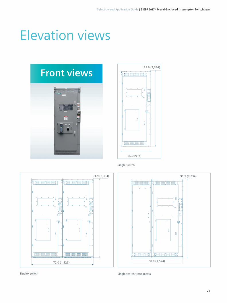
Elevation views
Single switch
Duplex switch
72.0 (1,829)
91.9 (2,334)
Front views
Single switch front access
60.0 (1,524)
91.9 (2,334)
36.0 (914)
91.9 (2,334)

22
SIEBREAK™ Metal-Enclosed Interrupter Switchgear | Selection and Application Guide
Indoor - single, duplex or selector switch 72”
72.0 (1,829)
91.9 (2,334)
Outdoor - single, duplex, or selector switch
72.0 (1,829)
105.0 (2,667)
Side views

23
Selection and Application Guide | SIEBREAK™ Metal-Enclosed Interrupter Switchgear
Section views
Duplex - bottom entry Duplex - top entry
72.0 (1,829)
77.1 (1,958)
91.9 (2,334)
72.0 (1,829)
61.9 (1,572)
91.9 (2,334)

Transformer terminations
24
SIEBREAK-VCB™ metal-enclosed interrupter switchgear | Selection and application guide
Indoor - dry transformer
Footnotes:1. This arrangement applies to indoor SIEBREAK-VCB switch 5 kV-15 kV up to 1,200 A termination with dry-type transformer termination.2. Filler strips at the ends of the transformer must be provided by the transformer supplier in case the transformer exceeds 92” (2,337 mm)
height and 56” (1,422 mm) depth.3. If cables are to be used for connections to transformer, transformer supplier to provide and install cable connections including lugs and
insulation on terminals if required. Maximum two x 500 kcmil cables per phase.4. If bus bars are to be used for connections to transformer, transformer supplier to provide and install required bus connections.
Transformer supplier also to provide and install flex connectors for connections to switchgear as well as insulation for flex connectors.5. Connect switchgear ground when continuous ground is required.6. Transformer supplier to provide necessary hardware (except nuts) for joining switchgear with transformer.7. Consult factory.
Five PEM nuts 3/
8-16 for
joining switchgear with transformer
92
.0 (
2,3
37
)
H1 (X3)
H2 (X2)
H3 (X1)
Swgr gnd (X0)
9.0 (229)
9.0 (229)
56.0 (1,422), 62.0 (1,575)7, 72.0 (1,829), or 82.0 (2,083) transformer to left of switchgear
(flush front transformer mounting)
36.0 (914)
Five PEM nuts 3/
8-16 for
joining switchgear with transformer
92
.0 (
2,3
37
)
H1 (X3)
H2 (X2)
H3 (X1)
Swgr gnd (X0)
9.0 (229)
9.0 (229)
56.0 (1,422), 62.0 (1,575)7, 72.0 (1,829), or 82.0 (2,083) transformer to right of switchgear
(flush front transformer mounting)
37
.5 (
95
3)
37
.5 (
95
3)
7.4 (188)
0.75 (19)
1.0 (25)
36
.5 (
92
7)
45
.0 (
1,1
43
)
13.6 (345)
18.5 (470)
4.1 (104)
0.75 (19)
0.25 (6)0.25 (6)
4.0 (102)
1.5 (38)
4.0 (102)
4.0 (102)4.0 (102)
11.6 (293)
36
.5 (
92
7)
45
.0 (
1,1
43
)
1.5 (38) 13.6
(345)18.5 (470)
4.1 (104)
0.75 (19)1.0
(25)
37
.5 (
95
3)
37
.5 (
95
3)
7.4 (188)

25
Selection and application guide | SIEBREAK-VCB™ metal-enclosed interrupter switchgear
Indoor - liquid-filled transformer
Footnotes:1. This arrangement applies to indoor SIEBREAK-VCB switch 5 kV-15 kV up to 1,200 A termination with liquid-filled type transformer
termination.2. This arrangement applies to bar-type connection to transformer only.3. Transformer supplier to provide insulation for termination.4. Consult factory.
Termination on left-hand side symmetrical to right-hand side except phase reversal
92
.0 (
2,3
37
)
H1 (X3)
H2 (X2)
H3 (X1)
33.55 (852)
Swgr gnd (X0)
8.0 (203)
8.0 (203)
56.0 (1,422), 62.0 (1,575)4, 72.0 (1,829), or 82.0 (2,083)
transformer to left of switchgear
18.0 (457)
33.55 (852)
c transformer throat
L
55
.0 (
1,3
97
)
36.0 (914)
18.0 (457)
55
.0 (
1,3
97
)
Termination on right-hand side symmetrical to left-hand side except phase reversal
9.5 (241.3)
H1 (X3)
H2 (X2)
H3 (X1)
8.0 (203)
8.0 (203)
c transformer throat
L
56.0 (1,422) transformer on the right side of the switchgear
92
.0 (
2,3
37
)
46
.8 (
1,1
89
)
44
.4 (
1,1
27
)
44
.4 (
1,1
27
)
Ø0.625
Maximum opening for transformer throat installation
26.9 (683)
Swgr gnd (X0)
64
.1 (
1,6
29
)
46
.8 (
1,1
89
)
19
.7 (
50
1)
42
.9 (
1,0
89
)
26
SIEBREAK-VCB™ metal-enclosed interrupter switchgear | Selection and application guide
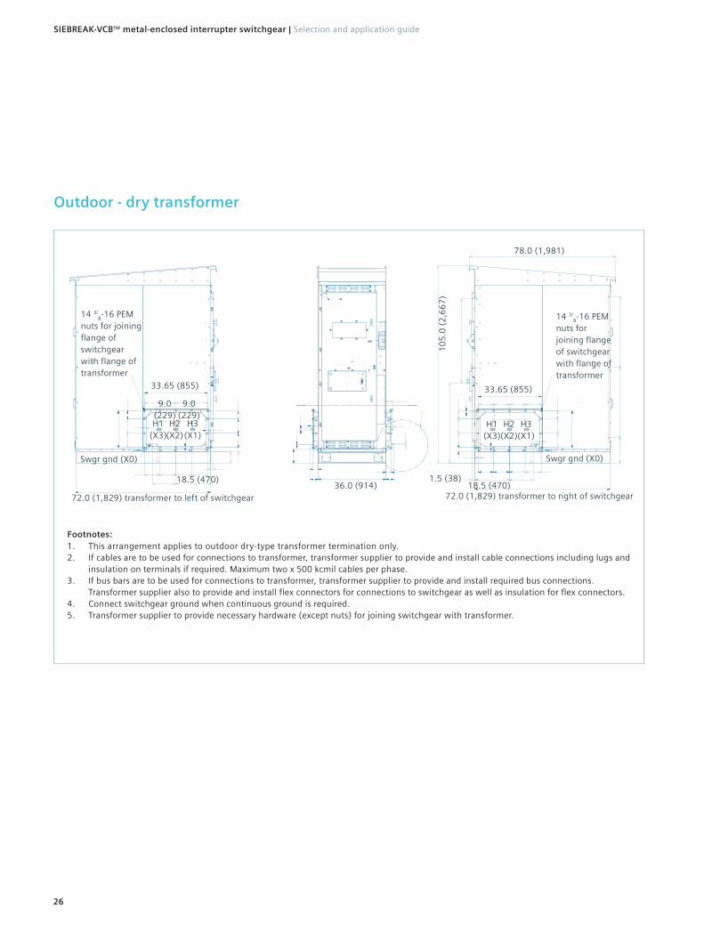
Outdoor - dry transformer
Footnotes:1. This arrangement applies to outdoor dry-type transformer termination only.2. If cables are to be used for connections to transformer, transformer supplier to provide and install cable connections including lugs and
insulation on terminals if required. Maximum two x 500 kcmil cables per phase.3. If bus bars are to be used for connections to transformer, transformer supplier to provide and install required bus connections.
Transformer supplier also to provide and install flex connectors for connections to switchgear as well as insulation for flex connectors.4. Connect switchgear ground when continuous ground is required.5. Transformer supplier to provide necessary hardware (except nuts) for joining switchgear with transformer.
14 3/8-16 PEM
nuts for joining flange of switchgear with flange of transformer
H1 (X3)
H2 (X2)
H3 (X1)
Swgr gnd (X0)
9.0 (229)
9.0 (229)
33.65 (855)
72.0 (1,829) transformer to left of switchgear
18.5 (470)36.0 (914)
14 3/8-16 PEM
nuts for joining flange of switchgear with flange of transformer
78.0 (1,981)
10
5.0
(2
,66
7)
H1 (X3)
H2 (X2)
H3 (X1)
72.0 (1,829) transformer to right of switchgear18.5 (470)
1.5 (38)
33.65 (855)
Swgr gnd (X0)
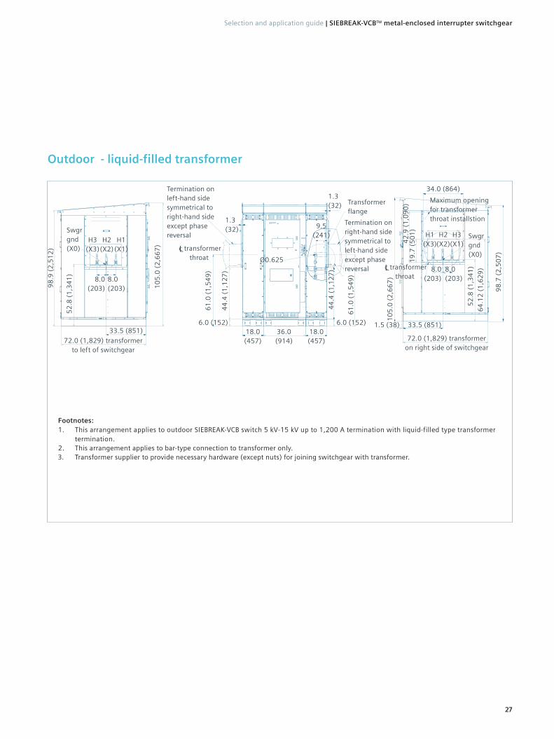
Outdoor - liquid-filled transformer
27
Selection and application guide | SIEBREAK-VCB™ metal-enclosed interrupter switchgear
Footnotes:1. This arrangement applies to outdoor SIEBREAK-VCB switch 5 kV-15 kV up to 1,200 A termination with liquid-filled type transformer
termination.2. This arrangement applies to bar-type connection to transformer only.3. Transformer supplier to provide necessary hardware (except nuts) for joining switchgear with transformer.
Termination on left-hand side symmetrical to right-hand side except phase reversal
98
.9 (
2,5
12
)
H3 (X3)
H2 (X2)
H1 (X1)
33.5 (851)
Swgr gnd (X0)
8.0 (203)
8.0 (203)
72.0 (1,829) transformer to left of switchgear
18.0 (457)
33.5 (851)
c transformer throat
L
61
.0 (
1,5
49
)
36.0 (914)
18.0 (457)
61
.0 (
1,5
49
)
Termination on right-hand side symmetrical to left-hand side except phase reversal
Transformer flange
H1 (X3)
H2 (X2)
H3 (X1)
Swgr gnd (X0)
8.0 (203)
8.0 (203)
c transformer throat
L
72.0 (1,829) transformer on right side of switchgear
98
.7 (
2,5
07
)
10
5.0
(2
,66
7)
64
.12
(1
,62
9)
10
5.0
(2
,66
7)
52
.8 (
1,3
41
)
44
.4 (
1,1
27
)
6.0 (152)
1.3 (32)
1.3 (32)
44
.4 (
1,1
27
)6.0 (152)
9.5 (241)
Ø0.625
34.0 (864)
52
.8 (
1,3
41
)
1.5 (38)
19
.7 (
50
1)
42
.9 (
1,0
90
) Maximum opening for transformer throat installstion

Circuit breaker ratings and optionsType SBVCB family of circuit breakers is equipped for medium- and heavy-duty medium-voltage commercial and industrial applications.
Available type SBVCB vacuum circuit breakers:
Circuit breaker options:
Features Options
Control voltage120 Vac1, 230 Vac1,
48 Vdc, 125 Vdc, 250 Vdc
Interrupting time 3-cycle standard
Trip coil
1 x trip coil
2 x trip coil
1 x trip coil and under voltage
Auxiliary contact 6 NO/6 NC, 12 NO/12 NC
Footnote:1. For ac control voltage, tripping employs capacitor trip.
Circuit breaker type1
Maximum design voltage
(V)2 kV rms
Voltage range factor (K)3
Withstand voltage levelsContinuous
current A rms
Short circuit (I)4,5,7 kA rms
sym
Interrupting time6
ms/cycles
Power frequency kV
rms
LIghtning impulse (BIL)
kV peak
05-SBVCB-25-xxxx-65 4.76 1.0 19 16 600, 1,200 25 50/3
05-SBVCB-40-xxxx-104 4.76 1.0 19 60 600, 1,200 387 50/3
15-SBVCB-25-xxxx-65 15.0 1.0 36 95 600, 1,200 25 50/3
15-SBVCB-40-xxxx-104 15.0 1.0 36 95 600, 1,200 387 50/3
Circuit breaker type1
Permissible tripping delay
(Y) sec
Maximum symmetrical
interrupting (I) kA rms sym
%dc component %
Short-time current (I)
(three seconds) kA
rms
Closing and latching (momentary)
Asymmetrical(1.55 x I)kA rms
Peak(2.6 x I)kA peak
05-SBVCB-25-xxxx-65 2 25 47 25 39 65
05-SBVCB-40-xxxx-104 2 387 47 387 597 997
15-SBVCB-25-xxxx-65 2 25 47 25 39 65
15-SBVCB-40-xxxx-104 2 387 47 387 597 997
Footnotes:1. “xxxx” in type designation refers to the continuous current rating 0600 A or 1,200 A, as
appropriate. 2. Maximum design voltage for which the circuit breaker is designed and the upper limit
for operation.3. K is listed for information purposes only. For circuit breakers rated on a “constant kA”
ratings basis, the voltage range factor is 1.0.4. All values apply to polyphase and line-to-line faults.5. Standard duty cycle is O - 0.3s - CO - 3 min. - CO.6. Standard rating interrupting time is three-cycles (50 ms).7. 40 kA circuit breaker values are limited to the capabilities of the load-interrupter switch.
28
SIEBREAK-VCB™ metal-enclosed interrupter switchgear | Selection and application guide
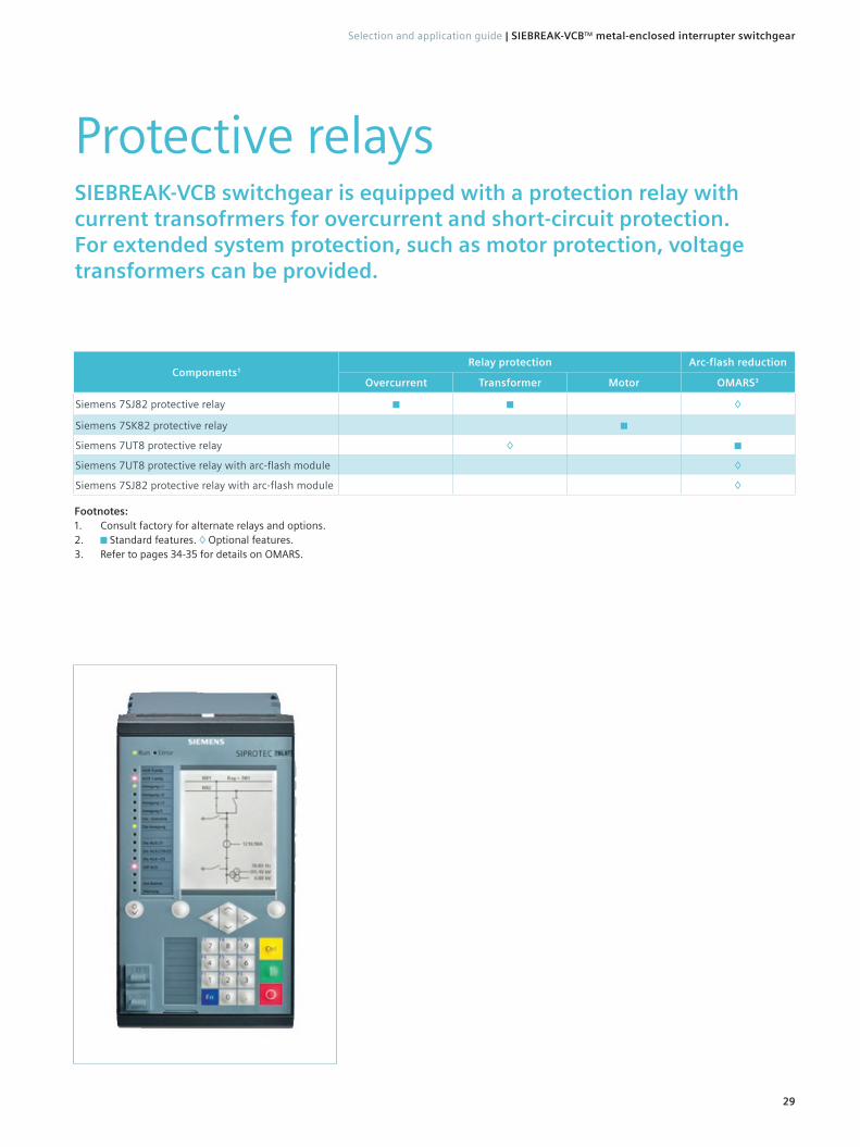
Protective relaysSIEBREAK-VCB switchgear is equipped with a protection relay with current transofrmers for overcurrent and short-circuit protection. For extended system protection, such as motor protection, voltage transformers can be provided.
Components1Relay protection Arc-flash reduction
Overcurrent Transformer Motor OMARS3
Siemens 7SJ82 protective relay ◊
Siemens 7SK82 protective relay
Siemens 7UT8 protective relay ◊
Siemens 7UT8 protective relay with arc-flash module ◊
Siemens 7SJ82 protective relay with arc-flash module ◊
Footnotes:1. Consult factory for alternate relays and options. 2. Standard features. ◊ Optional features.3. Refer to pages 34-35 for details on OMARS.
29
Selection and application guide | SIEBREAK-VCB™ metal-enclosed interrupter switchgear

Current transformers
Ratio50 Hz metering accuracy at burden Relay
classB0.1 B0.5 B0.9 B1.8
Type MD toroidal standard accuracy
100:5 2.4 ---- ---- ---- C 15
150:5 0.6 2.4 ---- ---- C 20
200:5 0.6 1.2 ---- ---- C 25
250:5 0.6 1.2 ---- ---- C 35
300:5 0.6 1.2 2.4 ---- C 40
400:5 0.3 0.6 2.4 ---- C 60
500:5 0.3 0.3 1.2 ---- C 75
600:5 0.3 0.3 0.6 ---- C 100
800:5 0.3 0.3 0.6 0.6 C 130
1,000:5 0.3 0.3 0.3 0.3 C 170
1,200:5 0.3 0.3 0.3 0.3 C 200
Voltage transformers
Voltage class kV
RatioAccuracy class VA
thermal ratingX, Y Z ZZ
5 2,400/120 0.3 1.2 ---- 500
5 4,200/120 0.3 1.2 ---- 500
5 4,800/120 0.3 1.2 ---- 500
15 7,200/120 0.3 0.3 1.2 1,000
15 8,400/120 0.3 0.3 1.2 1,000
15 12,000/120 0.3 0.3 1.2 1,000
15 14,400/120 0.3 0.3 1.2 1,000
Current transformersSIEBREAK-VCB switchgear includes current transformers for use with protective relays and power metering. The current transformers are located between the load side of the switch and the line side of the circuit breaker or optionally on the load side of the circuit breaker.
Voltage transformersSIEBREAK-VCB switchgear is available with voltage transformers as an option for voltage and power metering. The standard location of the voltage transformers is in the front above the switch.
Current transformers located between switch and circuit breaker of a duplex switch
Voltage transformers located above the switch
30
SIEBREAK-VCB™ metal-enclosed interrupter switchgear | Selection and application guide
Control power transformer
Primary voltage V
Secondary voltage V
Number of phases
Impulse level kV BIL
Thermal ratings1
5 kVA 10 kVA 15 kVA
2,400 120/240 1 60 √ √ √
4.160 120/240 1 60 √ √ √
4,800 120/240 1 60 √ √ √
7,200 120/240 1 95 √ √ √
8,400 120/240 1 95 √ √ √
12,000 120/240 1 95 √ √ √
12,470 120/240 1 95 √ √ √
13,200 120/240 1 95 √ √ √
13,800 120/240 1 95 √ √ √
14,400 120/240 1 95 √ √ √
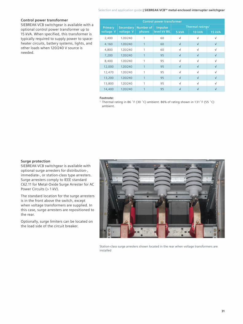
Station-class surge arresters shown located in the rear when voltage transformers are installed
Control power transformerSIEBREAK-VCB switchgear is available with a optional control power transformer up to 15 kVA. When specified, this transformer is typically required to supply power to space-heater circuits, battery systems, lights, and other loads when 120/240 V source is needed.
Surge protectionSIEBREAK-VCB switchgear is available with optional surge arresters for distribution-, immediate-, or station-class type arresters. Surge arresters comply to IEEE standard C62.11 for Metal-Oxide Surge Arrester for AC Power Circuits (> 1 kV).
The standard location for the surge arresters is in the front above the switch, except when voltage transformers are supplied. In this case, surge arresters are repositioned to the rear.
Optionally, surge limiters can be located on the load side of the circuit breaker.
31
Selection and application guide | SIEBREAK-VCB™ metal-enclosed interrupter switchgear
Footnote:1. Thermal rating in 86 ˚F (30 ˚C) ambient. 86% of rating shown in 131˚F (55 ˚C)
ambient.

MeteringSIEBREAK-VCB switchgear is equipped with standard current transformers. Optional voltage transformers can be provided with optional metering devices.
Functional overview (part 1 of 2)
Instrument variants Sentron PAC3100 PAC3200 PAC4200
Basic measurement variables
Voltage, current √ √ √
Neutral conductor current √ ---- √
Apparent power, active power, reactive power, power factor √ √ √
Power factor of the fundamental wave ---- ---- √
Frequency Of the reference phase √ √ √
Minimum/maximum valuesSlave pointer function Ӏ with date and time
√ Ӏ ---- √ Ӏ ---- √ Ӏ √
Power measurement
Apparent energy ---- √ √Active energy, reactive energy Input Ӏ Output Ӏ Balance √ Ӏ √ Ӏ √ √ Ӏ √ Ӏ ---- √ Ӏ √ Ӏ ----
Number of tariffs Apparent, active, and reactive energy 1 2 2
Daily energy values for 365 days Apparent, active, and reactive energy ---- ---- √Consumption recording of a sub-process or manufacturing process
Apparent, active, and reactive energy ---- ---- √
Power averages of the last measurement period
Active and reactive power average with minimum/maximum value
√ √ √
Load-profile record ---- ----√ maximum
3,840 entries1
E-counter for S0 signal at a digital input Electrical energy Ӏ any energy ---- Ӏ ---- √ Ӏ ---- √ Ӏ √
Accuracy class for active energy According to IEC 62053-21/62053-22 Class 1 Class 0.5 s Class 0.2 s
Accuracy class for reactive energy According to IEC 62053-23 Class 3 Class 2 Class 2
Monitoring of state of the plant and quality of the network
Configurable displaysFor presenting up to 4 measured quantities
---- ---- 4
Operating hours counter Operating hours of loads ---- √ √Sliding means values U, I, S, P, Q, LF ---- ---- √THD voltage, current ---- THD-R THD
Distortion current strength ---- ---- √Phase angle, phase-displacement angle ---- ---- √Unbalance Voltage Ӏ current ---- U
nba Ӏ
nba2 U
nb Ӏ
nb3
Harmonics in voltage, current ---- ---- 3 to 31st
Limit-value monitoring Maximum number of limit values ---- 6 12
Boolean logic For limit values Ӏ inputs ---- Ӏ ---- √ Ӏ ---- √ Ӏ √Event memory for operation, control, and system-related events
Including time stamp ---- ---- √ (> 4,000 events)
Battery backup for minimum/maximum values ---- ---- √
32
SIEBREAK-VCB™ metal-enclosed interrupter switchgear | Selection and application guide

Power meteringSIEBREAK-VCB switchgear is available with the optional Siemens SENTRON PAC compact and powerful power-monitoring devices. These devices are compact so they can be mounted on the front door of the SIEBREAK-VCB enclosure. Whether in industrial applications or commercial buildings, the SENTRON PAC power-monitoring devices can be employed wherever electric power is distributed and processed.
Functional overview (part 2 of 2)
Instrument variants Sentron PAC3100 PAC3200 PAC4200
System integration and communication
Ethernet (integrated)• Protocol• Gateway
Modbus TCPEthernet RS485 (Modbus)
---- ---- ----
10 Mbits/s √
----
10/100 Mbits/s √ √4
Profibus DP (V1) ---- Expansion module optional
RS485• Protocol
Modbus RTU
Integrated √
Expansion module optional √ √
4 DI/2 DO expansion module Expansion to maximum 10 DI/6 DO ---- ----√ (maximum 2
modules)
Number of expansion modules Maximum ---- 1 2
Integrated digital inputs (DI) Number Ӏ multifunctional 2 Ӏ ---- 1 Ӏ √ 2 Ӏ √
Integrated digital outputs (DO) Number Ӏ multifunctional 2 Ӏ √ 1 Ӏ √ 2 Ӏ √
Installation plan
Dimensions (length x width x depth) In in. (mm)3.78 x 3.78 x 2.20
(96 x 96 x 56)3.78 x 3.78 x 2.20
(96 x 96 x 56)3.78 x 3.78 x 3.23
(96 x 96 x 82)
Mounting depthPAC Ӏ PAC with expansion module in in. (mm)
2.01 (51) Ӏ ----2.01 (51) Ӏ 2.87 (73)
3.03 (77) Ӏ 3.90 (99)
Panel cut out (length x width) In in. (mm)3.62 x 3.62
(92 x 92)3.62 x 3.62
(92 x 92)3.62 x 3.62
(92 x 92)
Standards and approvals
UL / cUL √ √ √IEC 61557-12 √ ---- √
Footnotes:1. This corresponds, for example, to a duration of 40 days with a measurement period of 15 minutes.2. U
nba-I
nba - Unbalance with regard to amplitude.
3. Unb
-Inb
- Unbalance with regard to amplitude and phase.4. In conjunction with SENTRON PAC RS485 expansion module.5. √ Available --- Unavailable
33
Selection and application guide | SIEBREAK-VCB™ metal-enclosed interrupter switchgear

Components1Low-voltage circuit breaker configuration2 Virtual main configuration2
#1 #3 #2 #4
Siemens 7UT8 protective relay
Siemens 7UT8 protective relay with arc-flash module ◊ ◊ ◊ ◊
Siemens 7SJ82 protective relay ◊ ◊ ◊ ◊
Siemens 7SJ82 protective relay with arc-flash module ◊ ◊ ◊ ◊
Footnotes:1. Consult factory for alternate relays and options. 2. Standard features. ◊ Optional features.
Operation and maintenance arc-flash reduction system (OMARS)SIEBREAK-VCB configuration in low-voltage or medium-voltage substations SIEBREAK-VCB is available in four advanced configurations for reducing the incident arc-fault energy on the secondary bus of substation:
34
SIEBREAK-VCB™ metal-enclosed interrupter switchgear | Selection and application guide
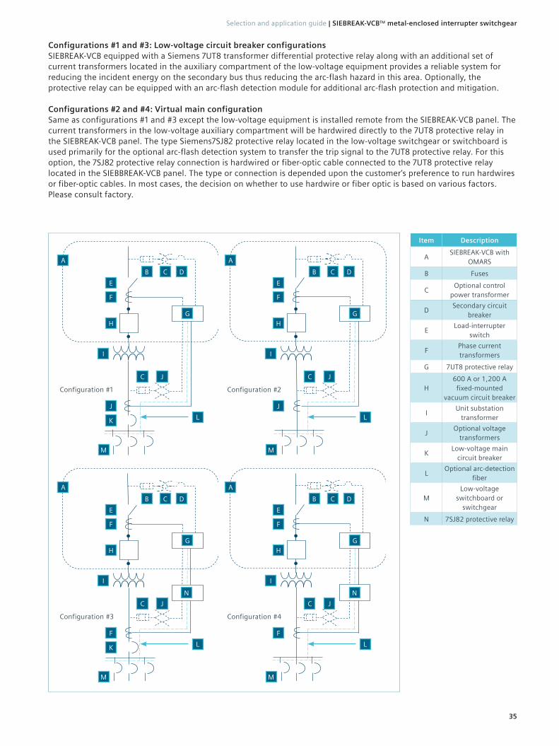
Item Description
ASIEBREAK-VCB with
OMARS
B Fuses
COptional control
power transformer
DSecondary circuit
breaker
ELoad-interrupter
switch
FPhase current transformers
G 7UT8 protective relay
H600 A or 1,200 A
fixed-mounted vacuum circuit breaker
IUnit substation
transformer
JOptional voltage
transformers
KLow-voltage main
circuit breaker
LOptional arc-detection
fiber
MLow-voltage
switchboard or switchgear
N 7SJ82 protective relay
Configuration #3
A
B C D
E
F
GH
I
C J
F
LK
M
Configuration #4
A
B C D
E
F
GH
I
C J
F
L
M
Configuration #1
A
B C D
E
F
GH
I
C J
J
LK
M
Configuration #2
A
B C D
E
F
GH
I
C J
J
L
M
N N
Configurations #1 and #3: Low-voltage circuit breaker configurations SIEBREAK-VCB equipped with a Siemens 7UT8 transformer differential protective relay along with an additional set of current transformers located in the auxiliary compartment of the low-voltage equipment provides a reliable system for reducing the incident energy on the secondary bus thus reducing the arc-flash hazard in this area. Optionally, the protective relay can be equipped with an arc-flash detection module for additional arc-flash protection and mitigation.
Configurations #2 and #4: Virtual main configurationSame as configurations #1 and #3 except the low-voltage equipment is installed remote from the SIEBREAK-VCB panel. The current transformers in the low-voltage auxiliary compartment will be hardwired directly to the 7UT8 protective relay in the SIEBREAK-VCB panel. The type Siemens7SJ82 protective relay located in the low-voltage switchgear or switchboard is used primarily for the optional arc-flash detection system to transfer the trip signal to the 7UT8 protective relay. For this option, the 7SJ82 protective relay connection is hardwired or fiber-optic cable connected to the 7UT8 protective relay located in the SIEBBREAK-VCB panel. The type or connection is depended upon the customer‘s preference to run hardwires or fiber-optic cables. In most cases, the decision on whether to use hardwire or fiber optic is based on various factors.Please consult factory.
35
Selection and application guide | SIEBREAK-VCB™ metal-enclosed interrupter switchgear
Published by Siemens Industry, Inc. 2019.
Siemens Industry 7000 Siemens Road Wendell, North Carolina 27591
For more information, including service or parts, please contact our Customer Support Center. Phone: 1-800-333-7421
www.usa.siemens.com/siebreak
Article No. EMMS-T40091-02-4AUS
Printed in U.S.A.
© 2019 Siemens Industry, Inc.
The technical data presented in this document is based on an actual case or on as-designed parameters, and therefore should not be relied upon for any specific application and does not constitute a performance guarantee for any projects. Actual results are dependent on variable conditions. Accordingly, Siemens does not make representations, warranties, or assurances as to the accuracy, currency or completeness of the content contained herein. If requested, we will provide specific technical data or specifications with respect to any customer’s particular applications. Our company is constantly involved in engineering and development. For that reason, we reserve the right to modify, at any time, the technology and product specifications contained herein.