silicon carbide electrical and thermal modeling ...neil/sic_workshop/presentations_2014/03...
TRANSCRIPT
Silicon Carbide Electrical and
Thermal Modeling, Characterization
and Device/Module Fabrication
Akin Akturk, Neil Goldsman,
James McGarrity, Siddharth Potbhare
Ronald Green and Aivars Lelis
1 11/4/2014
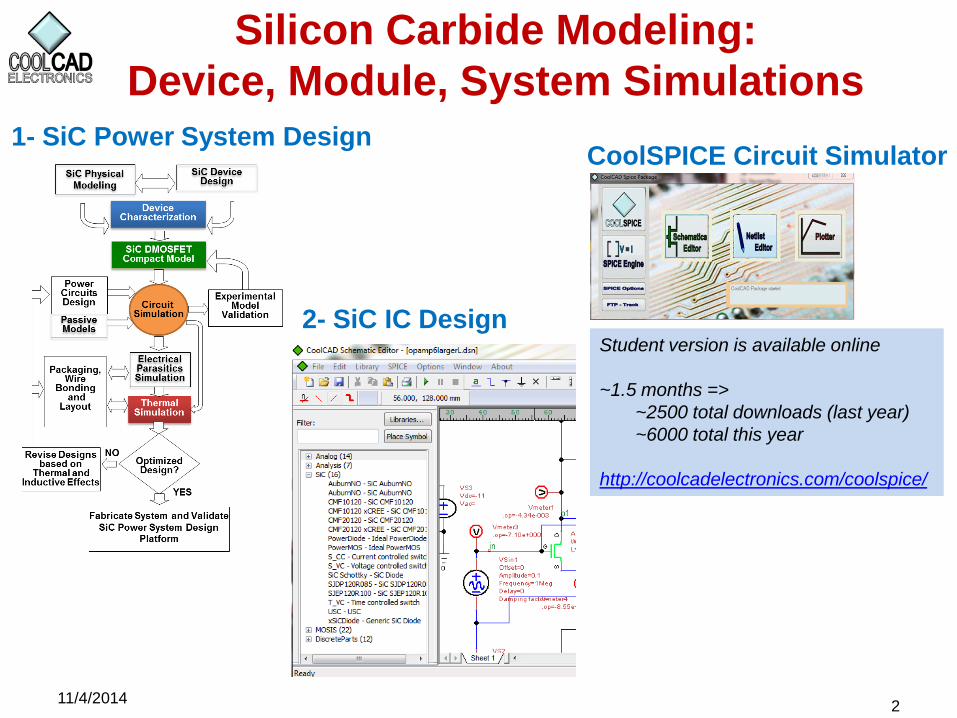
Silicon Carbide Modeling:
Device, Module, System Simulations
2
CoolSPICE Circuit Simulator 1- SiC Power System Design
11/4/2014
Student version is available online
~1.5 months =>
~2500 total downloads (last year)
~6000 total this year
http://coolcadelectronics.com/coolspice/
2- SiC IC Design
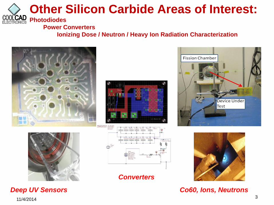
Other Silicon Carbide Areas of Interest: Photodiodes
Power Converters
Ionizing Dose / Neutron / Heavy Ion Radiation Characterization
3 11/4/2014
Deep UV Sensors Co60, Ions, Neutrons
Converters

CoolSPICE: SiC SPICE Simulator
11/4/2014 4
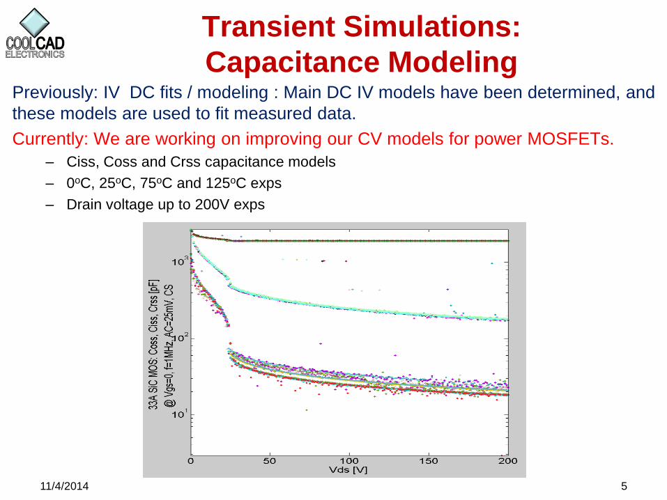
Transient Simulations:
Capacitance Modeling Previously: IV DC fits / modeling : Main DC IV models have been determined, and
these models are used to fit measured data.
Currently: We are working on improving our CV models for power MOSFETs.
– Ciss, Coss and Crss capacitance models
– 0oC, 25oC, 75oC and 125oC exps
– Drain voltage up to 200V exps
5 11/4/2014
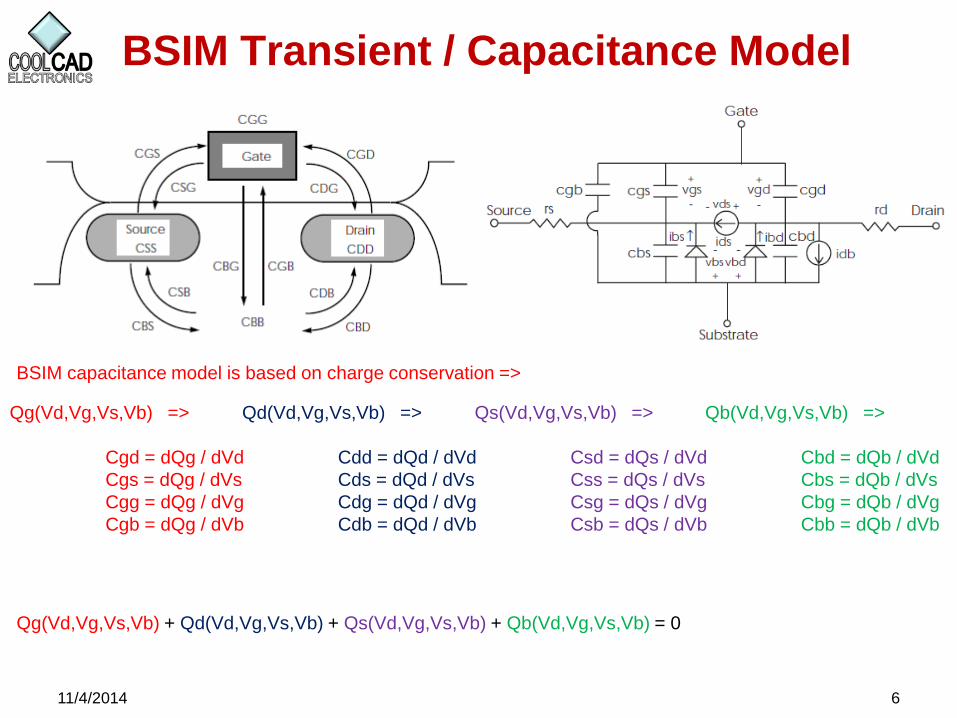
BSIM Transient / Capacitance Model
11/4/2014 6
BSIM capacitance model is based on charge conservation =>
Qg(Vd,Vg,Vs,Vb) =>
Cgd = dQg / dVd
Cgs = dQg / dVs
Cgg = dQg / dVg
Cgb = dQg / dVb
Qd(Vd,Vg,Vs,Vb) =>
Cdd = dQd / dVd
Cds = dQd / dVs
Cdg = dQd / dVg
Cdb = dQd / dVb
Qs(Vd,Vg,Vs,Vb) =>
Csd = dQs / dVd
Css = dQs / dVs
Csg = dQs / dVg
Csb = dQs / dVb
Qb(Vd,Vg,Vs,Vb) =>
Cbd = dQb / dVd
Cbs = dQb / dVs
Cbg = dQb / dVg
Cbb = dQb / dVb
Qg(Vd,Vg,Vs,Vb) + Qd(Vd,Vg,Vs,Vb) + Qs(Vd,Vg,Vs,Vb) + Qb(Vd,Vg,Vs,Vb) = 0
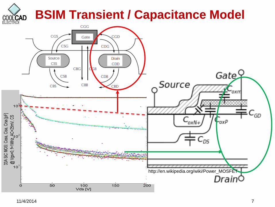
BSIM Transient / Capacitance Model
11/4/2014 7
http://en.wikipedia.org/wiki/Power_MOSFET
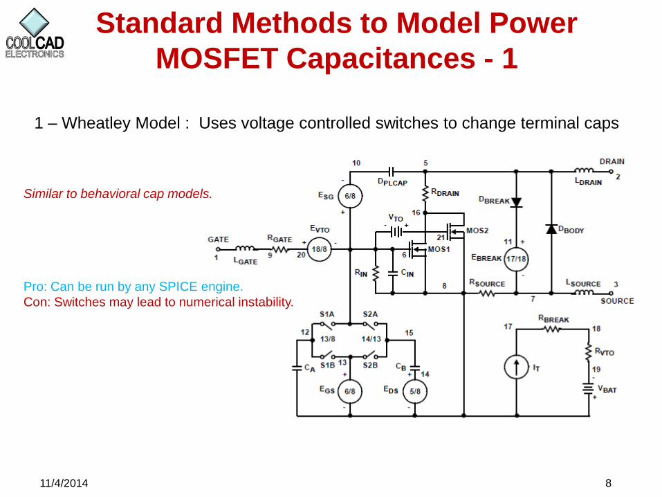
Standard Methods to Model Power
MOSFET Capacitances - 1
11/4/2014 8
1 – Wheatley Model : Uses voltage controlled switches to change terminal caps
Similar to behavioral cap models.
Pro: Can be run by any SPICE engine.
Con: Switches may lead to numerical instability.
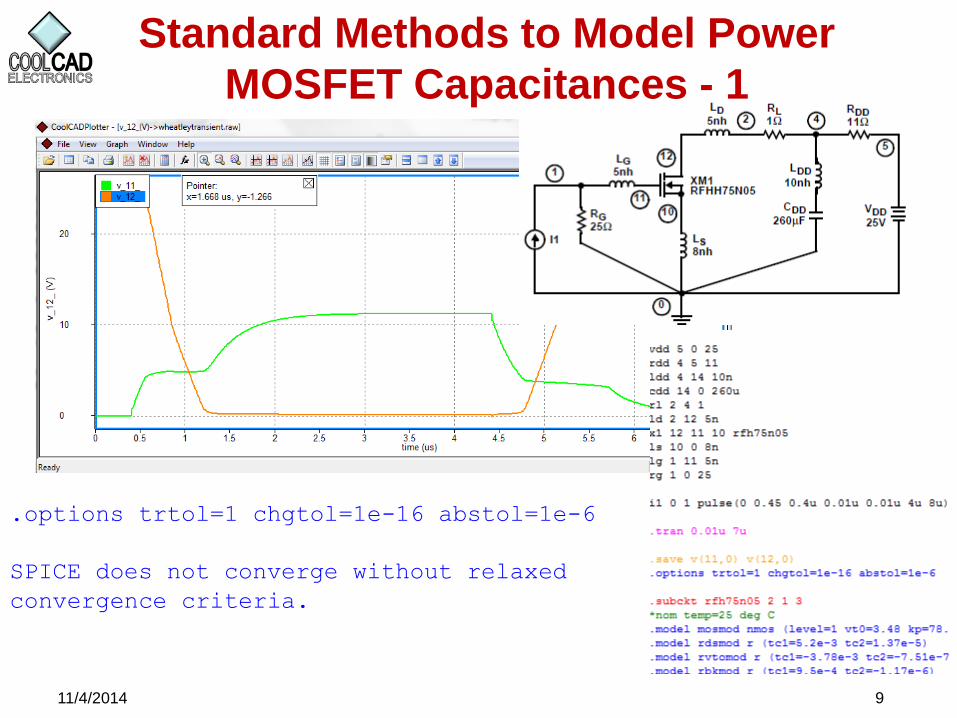
Standard Methods to Model Power
MOSFET Capacitances - 1
11/4/2014 9
.options trtol=1 chgtol=1e-16 abstol=1e-6
SPICE does not converge without relaxed
convergence criteria.
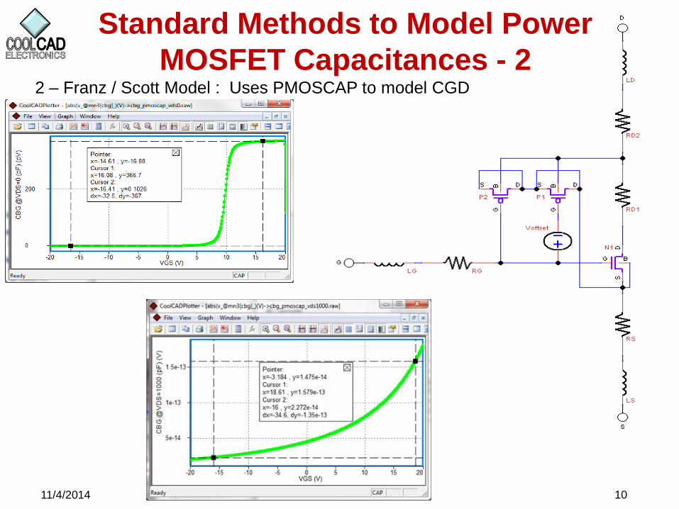
Standard Methods to Model Power
MOSFET Capacitances - 2
11/4/2014 10
2 – Franz / Scott Model : Uses PMOSCAP to model CGD
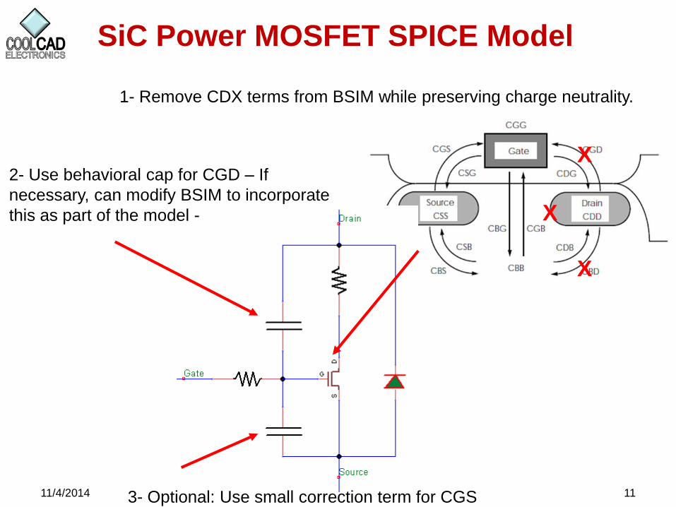
SiC Power MOSFET SPICE Model
11/4/2014 11
X
X
X
1- Remove CDX terms from BSIM while preserving charge neutrality.
3- Optional: Use small correction term for CGS
2- Use behavioral cap for CGD – If
necessary, can modify BSIM to incorporate
this as part of the model -
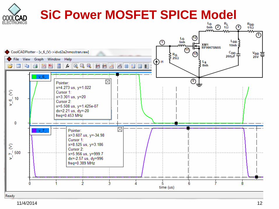
SiC Power MOSFET SPICE Model
11/4/2014 12
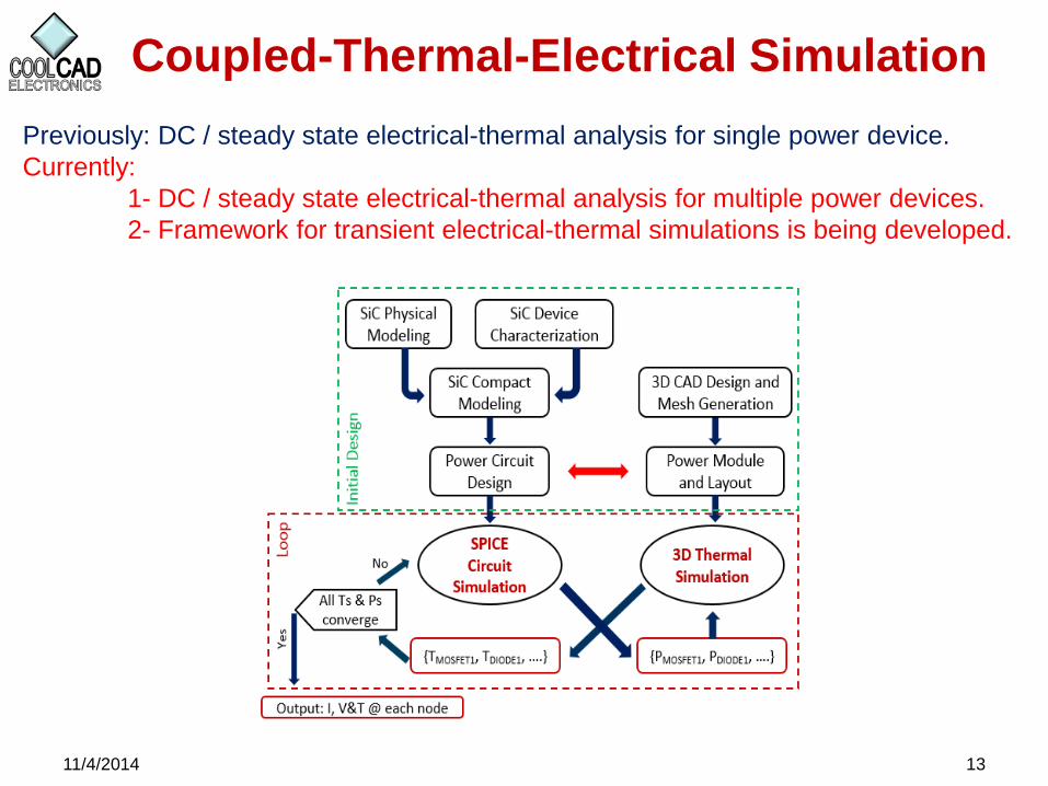
Coupled-Thermal-Electrical Simulation
11/4/2014 13
Previously: DC / steady state electrical-thermal analysis for single power device.
Currently:
1- DC / steady state electrical-thermal analysis for multiple power devices.
2- Framework for transient electrical-thermal simulations is being developed.
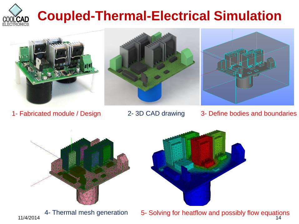
Coupled-Thermal-Electrical Simulation
11/4/2014 14
1- Fabricated module / Design 2- 3D CAD drawing 3- Define bodies and boundaries
4- Thermal mesh generation 5- Solving for heatflow and possibly flow equations
Coupled-Thermal-Electrical Simulation
11/4/2014 15
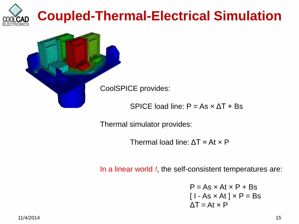
CoolSPICE provides:
SPICE load line: P = As × ΔT + Bs
Thermal simulator provides:
Thermal load line: ΔT = At × P
In a linear world !, the self-consistent temperatures are:
P = As × At × P + Bs
[ I - As × At ] × P = Bs
ΔT = At × P
Example: Thermal-Electrical Simulation
11/4/2014 16
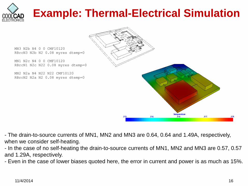
MN3 N2b N4 0 0 CMF10120
RBrcN3 N2b N2 0.08 myres dtemp=0
MN1 N2c N4 0 0 CMF10120
RBrcN1 N2c N22 0.08 myres dtemp=0
MN2 N2a N4 N22 N22 CMF10120
RBrcN2 N2a N2 0.08 myres dtemp=0
- The drain-to-source currents of MN1, MN2 and MN3 are 0.64, 0.64 and 1.49A, respectively,
when we consider self-heating.
- In the case of no self-heating the drain-to-source currents of MN1, MN2 and MN3 are 0.57, 0.57
and 1.29A, respectively.
- Even in the case of lower biases quoted here, the error in current and power is as much as 15%.
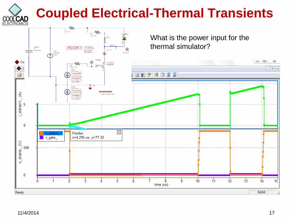
Coupled Electrical-Thermal Transients
11/4/2014 17
What is the power input for the
thermal simulator?
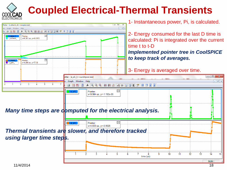
Coupled Electrical-Thermal Transients
11/4/2014 18
1- Instantaneous power, Pi, is calculated.
2- Energy consumed for the last D time is
calculated: Pi is integrated over the current
time t to t-D
Implemented pointer tree in CoolSPICE
to keep track of averages.
3- Energy is averaged over time.
Many time steps are computed for the electrical analysis.
Thermal transients are slower, and therefore tracked
using larger time steps.
SiC IC Development
11/4/2014 19
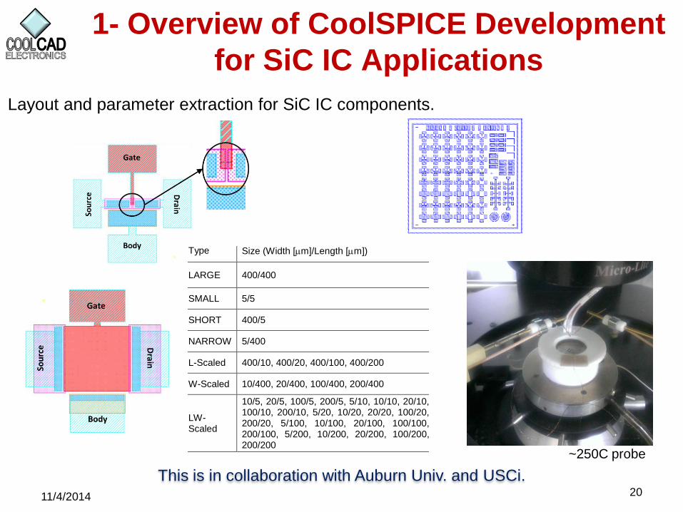
1- Overview of CoolSPICE Development
for SiC IC Applications
This is in collaboration with Auburn Univ. and USCi. 20 11/4/2014
Type Size (Width [m]/Length [m])
LARGE 400/400
SMALL 5/5
SHORT 400/5
NARROW 5/400
L-Scaled 400/10, 400/20, 400/100, 400/200
W-Scaled 10/400, 20/400, 100/400, 200/400
LW-Scaled
10/5, 20/5, 100/5, 200/5, 5/10, 10/10, 20/10, 100/10, 200/10, 5/20, 10/20, 20/20, 100/20, 200/20, 5/100, 10/100, 20/100, 100/100, 200/100, 5/200, 10/200, 20/200, 100/200, 200/200
Layout and parameter extraction for SiC IC components.
~250C probe
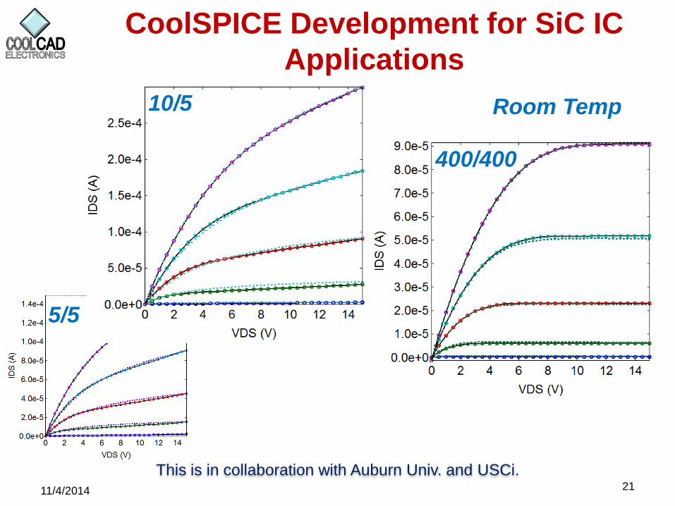
CoolSPICE Development for SiC IC
Applications
This is in collaboration with Auburn Univ. and USCi. 21 11/4/2014
5/5
10/5
400/400
Room Temp
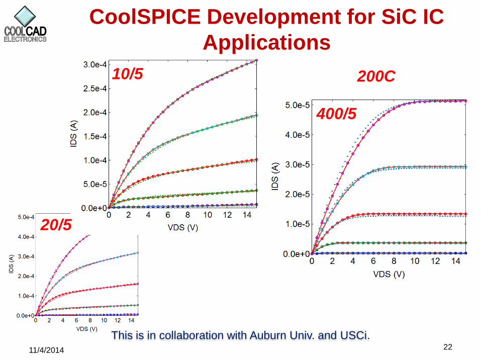
CoolSPICE Development for SiC IC
Applications
This is in collaboration with Auburn Univ. and USCi. 22 11/4/2014
20/5
10/5
400/5
200C

CoolSPICE Development for SiC IC
Applications
This is in collaboration with Auburn Univ. and USCi. 23 11/4/2014
High temperature nmos-
only op-amp design.
Terrestrial Neutron Induced Failure
in Silicon Carbide Power MOSFETs
11/4/2014 24
CoolCAD Electronics and Prairie View A&M Univ.
Presented at 2014 Nuclear and Space Radiation Effects Conference (NSREC):
“Terrestrial Neutron Induced Failure in Silicon Carbide Power MOSFETs”
Richard T. Wilkins, Kazi Rashed, Ramesh Dwivedi, Brad Gersey, Prairie View A&M
University; Akin Akturk, CoolCAD Electronics LLC
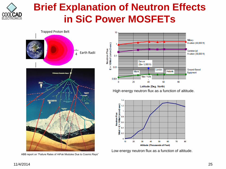
Brief Explanation of Neutron Effects
in SiC Power MOSFETs
11/4/2014 25
Earth Radii
Trapped Proton Belt
4
ABB report on “Failure Rates of HiPak Modules Due to Cosmic Rays”
Low energy neutron flux as a function of altitude.
High energy neutron flux as a function of altitude.
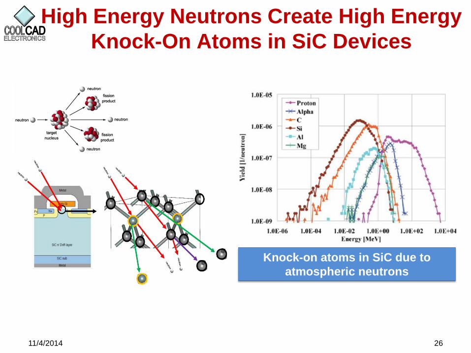
High Energy Neutrons Create High Energy
Knock-On Atoms in SiC Devices
11/4/2014 26
Knock-on atoms in SiC due to
atmospheric neutrons
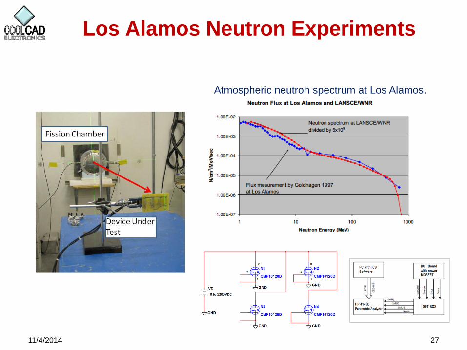
Los Alamos Neutron Experiments
11/4/2014 27
Atmospheric neutron spectrum at Los Alamos.
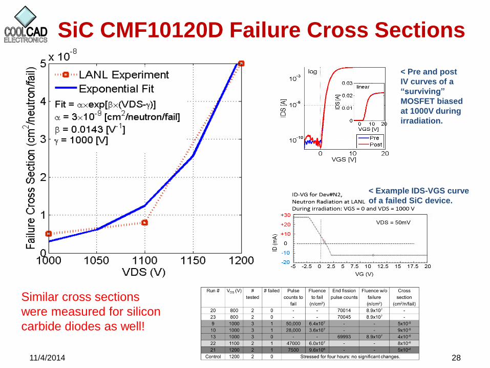
SiC CMF10120D Failure Cross Sections
11/4/2014 28
< Pre and post
IV curves of a
“surviving”
MOSFET biased
at 1000V during
irradiation.
< Example IDS-VGS curve
of a failed SiC device.
Similar cross sections
were measured for silicon
carbide diodes as well!

SiC CMF10120D Failure Predictions
11/4/2014 29
Failures / Year = N x λ x σ x t x d [fail/yr]
where
N = # devices in application
λ = neutron flux at location [n/cm2/hr]
σ = failure cross section at Vds [cm2/n/fail]
t = operating hours per year [hr/yr]
d = duty cycle [hr/hr]
Army:
100 devices/veh x 20 n/cm2/hr x 5 x 10⁻⁸ @ 1200V x 400
hr/yr x 0.5 = 2 x 10⁻² / yr
=> 1 Failure / 50 yrs per vehicle
(x thousands of vehicles ?)
Wind turbine (low altitude):
50 devices/turbine x 20 n/cm2/ hr x 5 x 10⁻⁸ @ 1200V x 9000
hr/yr x 0.5 = 2.25 x 10⁻¹ / yr
=> 2 Failures / 10 yrs per wind turbine
(100s of turbines ?)
Air Force:
100 devices/aircraft x 6000 n/cm2/hr x 5 x 10⁻⁸ @ 1200V x
1000 hr/yr x 0.5 = 15
=> 15 Failures /1 yr per aircraft
(100s of aircraft ?)