simatic s5 profibusdp - manual driver ma-00327-a (12.00).pdf
TRANSCRIPT

8/10/2019 SIMATIC S5 ProfibusDP - Manual Driver MA-00327-A (12.00).PDF
http://slidepdf.com/reader/full/simatic-s5-profibusdp-manual-driver-ma-00327-a-1200pdf 1/49
Driver for Siemens SIMATIC S5 PROFIBUS DP
English
Svenska
© Beijer Electronics AB 2000, MA00327A, 2000-12
Beijer Electronics AB reserves the right to change information in this manual without
prior notice. All examples in this manual are used solely to promote understanding ofhow the program works and its operation. Beijer Electronics AB take no responsibility ifthese examples are used in real applications.
8/10/2019 SIMATIC S5 ProfibusDP - Manual Driver MA-00327-A (12.00).PDF
http://slidepdf.com/reader/full/simatic-s5-profibusdp-manual-driver-ma-00327-a-1200pdf 2/49
Siemens SIMATIC S5 PROFIBUS DP
This manual presents installation and handling of the driver SIMATIC S5Profibus DP to the terminals in the E-series.
The functionality in the E-terminals and in MAC Programmer+
are described in the E-manual.
© Beijer Electronics AB 2000, MA00327A, 2000-12
Beijer Electronics AB reserves the right to change information in this manual withoutprior notice. All examples in this manual are used solely to promote understanding ofhow the program works and its operation. Beijer Electronics AB take no responsibility ifthese examples are used in real applications.

8/10/2019 SIMATIC S5 ProfibusDP - Manual Driver MA-00327-A (12.00).PDF
http://slidepdf.com/reader/full/simatic-s5-profibusdp-manual-driver-ma-00327-a-1200pdf 3/49
Content
Content
1 Introduction ...........................................................................................3
2 Install and update driver .......................................................................4
2.1 Installation of driver using Internet..................................................4
2.2 Installation of driver from disk.........................................................4
3 Connecting the terminal to the PLC system .........................................5
3.1 Settings in the MAC Programmer+ ..................................................5
3.2 Connecting the terminal to the Profibus DP network ......................8
3.3 Communication settings for the IFC PBDP card ..............................8
3.4 Cable to PROFIBUS-DP ....................................................................8
3.5 Technical data ...................................................................................9
3.6 Description of the PLC program section........................................10
4 Addressing ...........................................................................................13
5 The MMI profile ..................................................................................15
5.1 The data exchange ..........................................................................15
5.2 The request and response containers .............................................16
5.3 The index structure .........................................................................18
6 Efficient communication .....................................................................20
6.1 Signals affecting the communication time......................................20
6.2 How to make the communication more efficient ...........................21
7 Drawings ..............................................................................................22

8/10/2019 SIMATIC S5 ProfibusDP - Manual Driver MA-00327-A (12.00).PDF
http://slidepdf.com/reader/full/simatic-s5-profibusdp-manual-driver-ma-00327-a-1200pdf 4/49
Introduction
3
1 Introduction
This manual describes how the SIMATIC S5 PLC system is connected tothe terminals in the E-series via the fieldbus Profibus DP. Addressing of anitem in the PLC system is done in the normal Siemens way.For information about the PLC system we refer to the manual for thecurrent system.
The terminals support the systems SIMATIC S5 90, 115, 135 and 155.
The expansion card IFC PBDP must be installed in the terminal.See the IFC PBDP manual.
8/10/2019 SIMATIC S5 ProfibusDP - Manual Driver MA-00327-A (12.00).PDF
http://slidepdf.com/reader/full/simatic-s5-profibusdp-manual-driver-ma-00327-a-1200pdf 5/49
Install and update driver
4
2 Install and update driver
When installing MAC Programmer+ the drivers available at the time ofrelease are installed too. A new driver can be added into MAC Program-mer+ either with MAC Programmer+ using an Internet connection orfrom diskette. A driver can be updated to a newer version in the sameways.
2.1 Installation of driver using Internet
To update available drivers to the latest version or to install new driversyou can use the function Update terminal drivers, from Internet in the Filemenu in MAC Programmer+. All projects must be closed before this func-tion is used and the computer must be able to make an Internet connec-tion. You don’t need a browser. When the connection is established a list
is shown with all drivers that can be downloaded from Internet to thecomputer. The list shows the version number of available drivers and theversion number of installed drivers. Mark the driver/drivers you want toinstall in the MAC Programmer+. The function Mark Newer will mark alldrivers that are available in a newer version than the one installed and thedrivers not installed. Then you select Download. Each driver is approx-imately 500 kb and it is ready to use when the download is ready.
2.2 Installation of driver from disk
To update available drivers to the latest version or to install new drivers
you can use the function Update terminal drivers, from Disk in the Filemenu in MAC Programmer+. All projects must be closed before this func-tion is used. Select the folder with the new driver and choose to open thempd-file. A list is shown with all drivers that can be installed showing theversion number of available drivers and the version number of installeddrivers. Mark the driver/drivers you want to install in the MAC Program-mer+. The function Mark Newer will mark all drivers that are available ina newer version than the one installed and the drivers not installed. Thenyou select Install.
How to select the SIMATIC S5 Profibus DP driver in the project and howto transfer it to the terminal are described in chapter 3.
8/10/2019 SIMATIC S5 ProfibusDP - Manual Driver MA-00327-A (12.00).PDF
http://slidepdf.com/reader/full/simatic-s5-profibusdp-manual-driver-ma-00327-a-1200pdf 6/49
Connecting the terminal to the PLC system
5
3 Connecting the terminal to the
PLC system
3.1 Settings in the MAC Programmer+For communication with SIMATIC S5 PLC system via the fieldbusProfibus DP the following settings must be made in the programming toolMAC Programmer+.
Driver selection
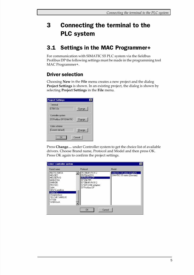
Choosing New in the File menu creates a new project and the dialogProject Settings is shown. In an existing project, the dialog is shown byselecting Project Settings in the File menu.
PressChange… under Controller system to get the choice list of availabledrivers. Choose Brand name, Protocol and Model and then press OK.Press OK again to confirm the project settings.
8/10/2019 SIMATIC S5 ProfibusDP - Manual Driver MA-00327-A (12.00).PDF
http://slidepdf.com/reader/full/simatic-s5-profibusdp-manual-driver-ma-00327-a-1200pdf 7/49
Connecting the terminal to the PLC system
6
Communication setup
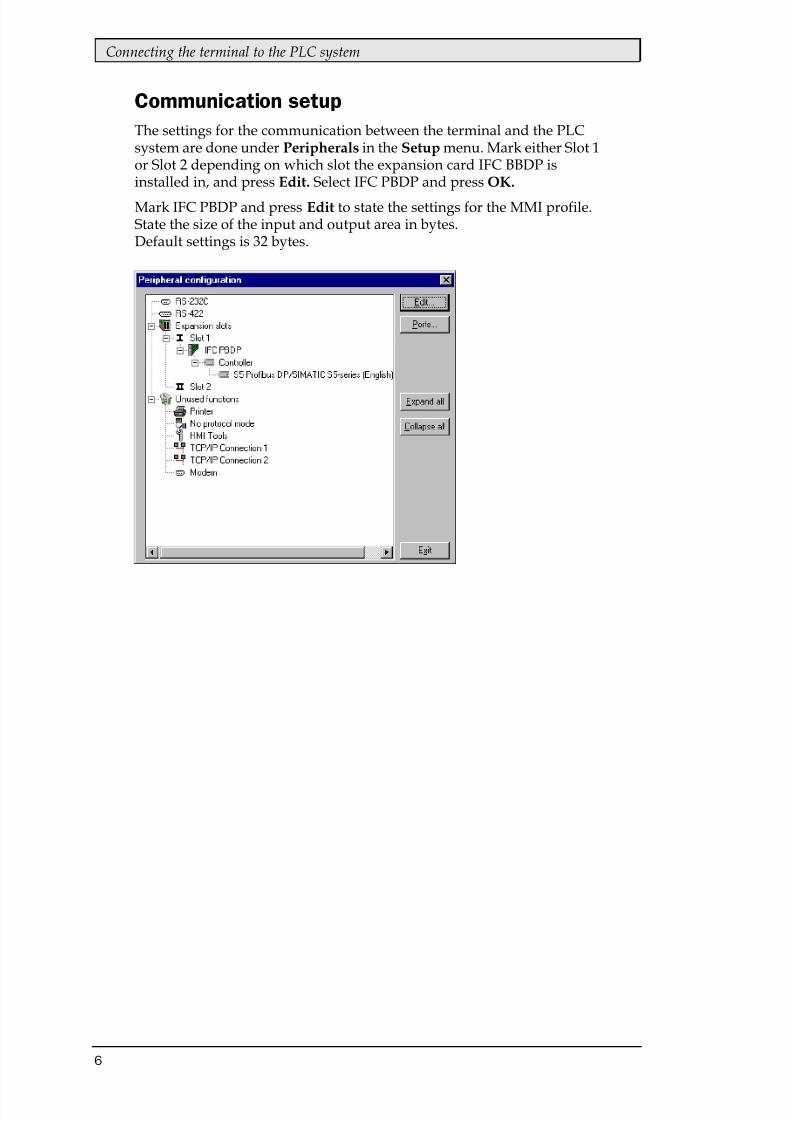
The settings for the communication between the terminal and the PLCsystem are done under Peripherals in the Setup menu. Mark either Slot 1or Slot 2 depending on which slot the expansion card IFC BBDP isinstalled in, and press Edit. Select IFC PBDP and press OK.
Mark IFC PBDP and press Edit to state the settings for the MMI profile.State the size of the input and output area in bytes.Default settings is 32 bytes.
8/10/2019 SIMATIC S5 ProfibusDP - Manual Driver MA-00327-A (12.00).PDF
http://slidepdf.com/reader/full/simatic-s5-profibusdp-manual-driver-ma-00327-a-1200pdf 8/49
Connecting the terminal to the PLC system
7
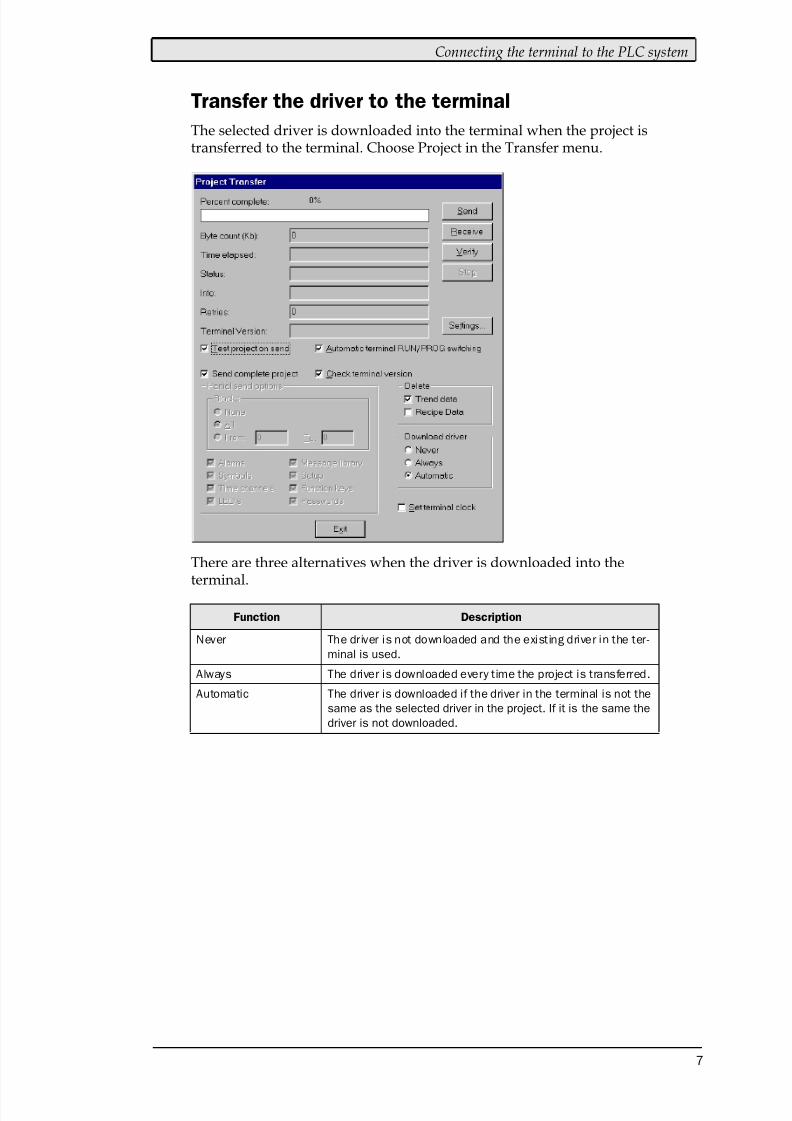
Transfer the driver to the terminal
The selected driver is downloaded into the terminal when the project istransferred to the terminal. Choose Project in the Transfer menu.
There are three alternatives when the driver is downloaded into theterminal.
Function Description
Never The driver is not downloaded and the existing driver in the ter-
minal is used.
Always The driver is downloaded every time the project is transferred.
Automatic The driver is downloaded if the driver in the terminal is not the
same as the selected driver in the project. If it is the same the
driver is not downloaded.
8/10/2019 SIMATIC S5 ProfibusDP - Manual Driver MA-00327-A (12.00).PDF
http://slidepdf.com/reader/full/simatic-s5-profibusdp-manual-driver-ma-00327-a-1200pdf 9/49
Connecting the terminal to the PLC system
8
3.2 Connecting the terminal to the
Profibus DP network
With the expansion card IFC PBDP the terminal can then be connected toa Profibus DP network as a slave. The PLC system in the network most be
loaded with a program handling the communication between the termi-nal and the PLC system.
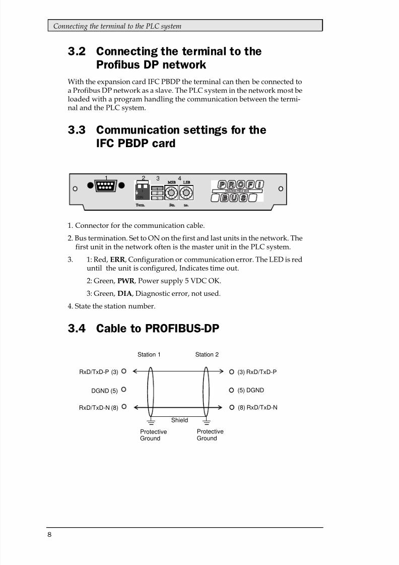
3.3 Communication settings for the
IFC PBDP card
1. Connector for the communication cable.
2. Bus termination. Set to ON on the first and last units in the network. Thefirst unit in the network often is the master unit in the PLC system.
3. 1: Red, ERR, Configuration or communication error. The LED is reduntil the unit is configured, Indicates time out.
2: Green, PWR, Power supply 5 VDC OK.
3: Green, DIA, Diagnostic error, not used.4. State the station number.
3.4 Cable to PROFIBUS-DP
0 01 12 2
3 3
4
5 6
4
5 6
7 7
8 8 9 9
Term Stn no
MS LS
ON
1
1 2 3 4
12
3
(3) RxD/TxD-P
(5) DGND
(8) RxD/TxD-NRxD/TxD-N (8)
DGND (5)
RxD/TxD-P (3)
ProtectiveGround
Shield
ProtectiveGround
Station 2Station 1
8/10/2019 SIMATIC S5 ProfibusDP - Manual Driver MA-00327-A (12.00).PDF
http://slidepdf.com/reader/full/simatic-s5-profibusdp-manual-driver-ma-00327-a-1200pdf 10/49
Connecting the terminal to the PLC system
9
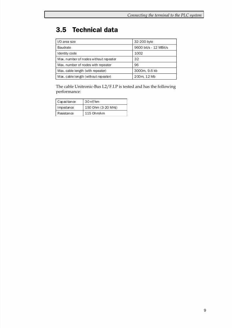
3.5 Technical data
The cable Unitronic-Bus L2/F.I.P is tested and has the followingperformance:
8/10/2019 SIMATIC S5 ProfibusDP - Manual Driver MA-00327-A (12.00).PDF
http://slidepdf.com/reader/full/simatic-s5-profibusdp-manual-driver-ma-00327-a-1200pdf 11/49
Connecting the terminal to the PLC system
10
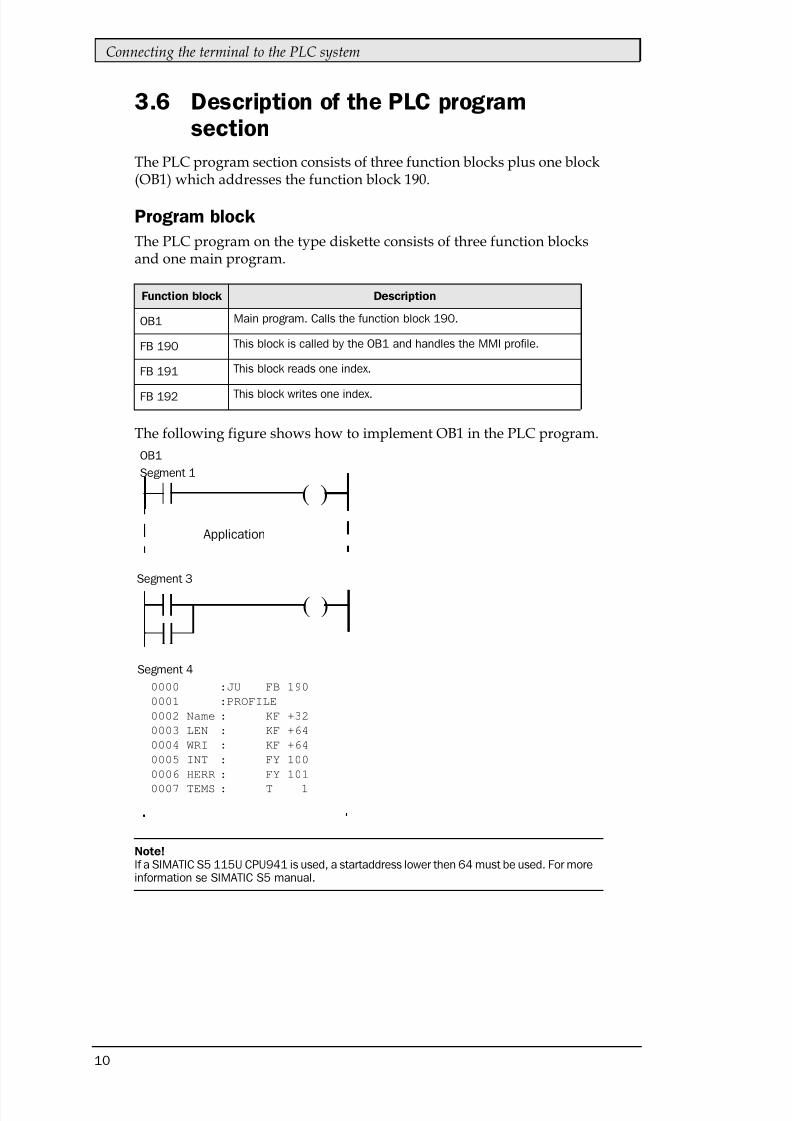
3.6 Description of the PLC program
section
The PLC program section consists of three function blocks plus one block(OB1) which addresses the function block 190.
Program block
The PLC program on the type diskette consists of three function blocksand one main program.
The following figure shows how to implement OB1 in the PLC program.
( )
( )
0000 :JU FB 190
0001 :PROFILE
0002 Name : KF +32
0003 LEN : KF +64
0004 WRI : KF +64
0005 INT : FY 100
0006 HERR : FY 101
0007 TEMS : T 1
8/10/2019 SIMATIC S5 ProfibusDP - Manual Driver MA-00327-A (12.00).PDF
http://slidepdf.com/reader/full/simatic-s5-profibusdp-manual-driver-ma-00327-a-1200pdf 12/49
Connecting the terminal to the PLC system
11
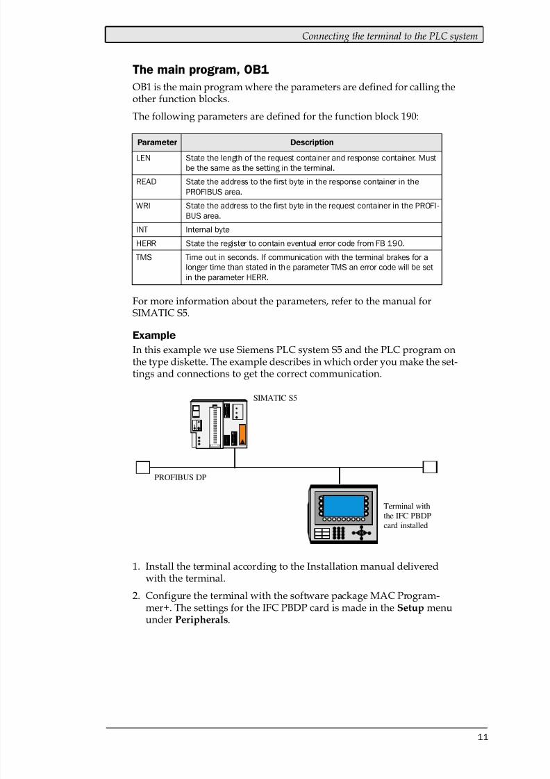
The main program, OB1
OB1 is the main program where the parameters are defined for calling theother function blocks.
The following parameters are defined for the function block 190:
For more information about the parameters, refer to the manual forSIMATIC S5.
In this example we use Siemens PLC system S5 and the PLC program onthe type diskette. The example describes in which order you make the set-tings and connections to get the correct communication.
1. Install the terminal according to the Installation manual deliveredwith the terminal.
2. Configure the terminal with the software package MAC Program-mer+. The settings for the IFC PBDP card is made in the Setup menuunder Peripherals.
Terminal with
the IFC PBDP
SIMATIC S5
PROFIBUS DP
card installed

8/10/2019 SIMATIC S5 ProfibusDP - Manual Driver MA-00327-A (12.00).PDF
http://slidepdf.com/reader/full/simatic-s5-profibusdp-manual-driver-ma-00327-a-1200pdf 13/49
Connecting the terminal to the PLC system
12
3. Start the COM Profibus configuration software.
4. Configure the master, baudrate, station number, number of bytes inthe transfer container etc. For more information, refer to the softwaremanual. Type files for the terminal are available on the IFC PBDP dis-kette.
5. Load the configuration to the S5. See the SIMATIC S5 manual.
6. Load the enclosed PLC program to the S5.
7. Connect the cable between the S5 system and the IFC PBDP card in theterminal.
8. Put the PLC system and the terminal in run mode.
Note!If you try to open a non-existent data block the PLC system will stop. For moreinformation, refer to the SIMATIC manual.
8/10/2019 SIMATIC S5 ProfibusDP - Manual Driver MA-00327-A (12.00).PDF
http://slidepdf.com/reader/full/simatic-s5-profibusdp-manual-driver-ma-00327-a-1200pdf 14/49
Addressing
13
4 Addressing
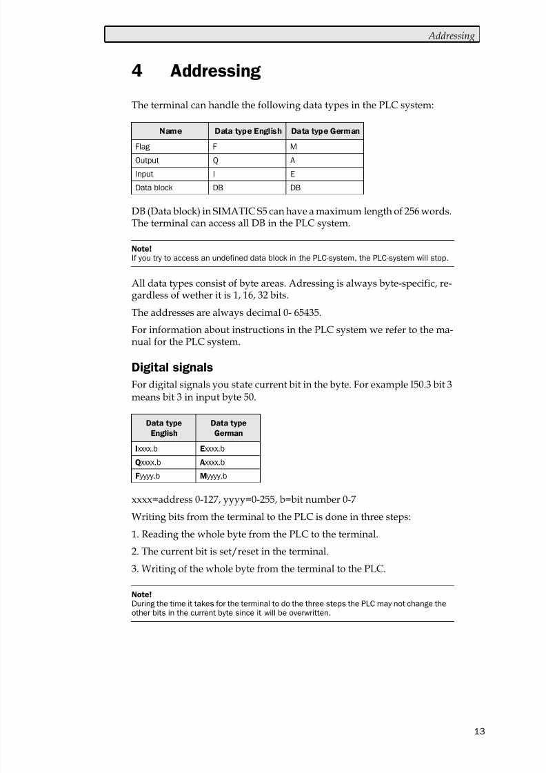
The terminal can handle the following data types in the PLC system:
DB (Data block) in SIMATIC S5 can have a maximum length of 256 words.The terminal can access all DB in the PLC system.
All data types consist of byte areas. Adressing is always byte-specific, re-gardless of wether it is 1, 16, 32 bits.
The addresses are always decimal 0- 65435.
For information about instructions in the PLC system we refer to the ma-nual for the PLC system.
Digital signals
For digital signals you state current bit in the byte. For example I50.3 bit 3means bit 3 in input byte 50.
xxxx=address 0-127, yyyy=0-255, b=bit number 0-7
Writing bits from the terminal to the PLC is done in three steps:
1. Reading the whole byte from the PLC to the terminal.
2. The current bit is set/reset in the terminal.
3. Writing of the whole byte from the terminal to the PLC.
Note!If you try to access an undefined data block in the PLC-system, the PLC-system will stop.
Data type
English
Data type
German
Note!During the time it takes for the terminal to do the three steps the PLC may not change theother bits in the current byte since it will be overwritten.
8/10/2019 SIMATIC S5 ProfibusDP - Manual Driver MA-00327-A (12.00).PDF
http://slidepdf.com/reader/full/simatic-s5-profibusdp-manual-driver-ma-00327-a-1200pdf 15/49
Addressing
14
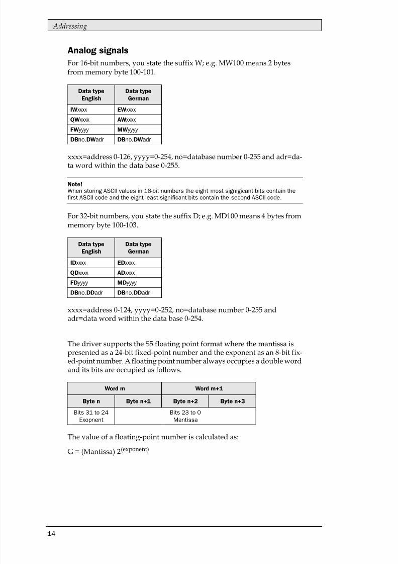
Analog signals
For 16-bit numbers, you state the suffix W; e.g. MW100 means 2 bytesfrom memory byte 100-101.
xxxx=address 0-126, yyyy=0-254, no=database number 0-255 and adr=da-ta word within the data base 0-255.
For 32-bit numbers, you state the suffix D; e.g. MD100 means 4 bytes frommemory byte 100-103.
xxxx=address 0-124, yyyy=0-252, no=database number 0-255 andadr=data word within the data base 0-254.
The driver supports the S5 floating point format where the mantissa ispresented as a 24-bit fixed-point number and the exponent as an 8-bit fix-ed-point number. A floating point number always occupies a double wordand its bits are occupied as follows.
The value of a floating-point number is calculated as:
G = (Mantissa) 2(exponent)
Data type
English
Data type
German
Note!When storing ASCII values in 16-bit numbers the eight most signigicant bits contain the
first ASCII code and the eight least significant bits contain the second ASCII code.
Data type
English
Data type
German
Word m Word m+1
Byte n Byte n+1 Byte n+2 Byte n+3
Bits 31 to 24
Exopnent
Bits 23 to 0
Mantissa
8/10/2019 SIMATIC S5 ProfibusDP - Manual Driver MA-00327-A (12.00).PDF
http://slidepdf.com/reader/full/simatic-s5-profibusdp-manual-driver-ma-00327-a-1200pdf 16/49
The MMI profile
15
5 The MMI profile
This chapter describes setup of the MMI profile, and is for the benefit ofreaders who want to learn more about data exchange via the MMI profile.
The MMI profile allows exchange of an unlimited amount of data, andalso allows the terminal to access all type of devices in the PLC system.
Together with the card a type diskette is supplied containing PLCprogram for communication with different PLC system.
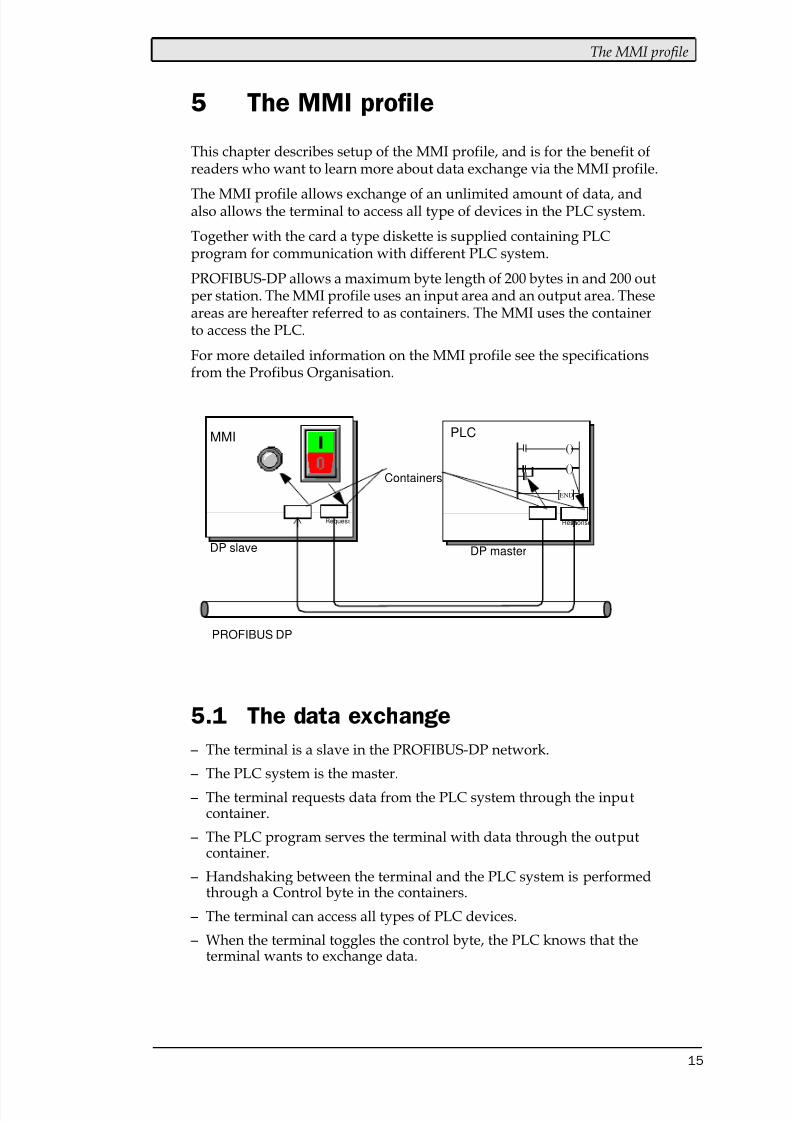
PROFIBUS-DP allows a maximum byte length of 200 bytes in and 200 outper station. The MMI profile uses an input area and an output area. Theseareas are hereafter referred to as containers. The MMI uses the containerto access the PLC.
For more detailed information on the MMI profile see the specificationsfrom the Profibus Organisation.
5.1 The data exchange
– The terminal is a slave in the PROFIBUS-DP network.
– The PLC system is the master.
– The terminal requests data from the PLC system through the inputcontainer.
– The PLC program serves the terminal with data through the outputcontainer.
– Handshaking between the terminal and the PLC system is performedthrough a Control byte in the containers.
– The terminal can access all types of PLC devices.
– When the terminal toggles the control byte, the PLC knows that theterminal wants to exchange data.
()
()
PLCMMI
][END
PROFIBUS DP
DP slave DP master
ResponseRequest
Containers
8/10/2019 SIMATIC S5 ProfibusDP - Manual Driver MA-00327-A (12.00).PDF
http://slidepdf.com/reader/full/simatic-s5-profibusdp-manual-driver-ma-00327-a-1200pdf 17/49
The MMI profile
16
5.2 The request and response containers
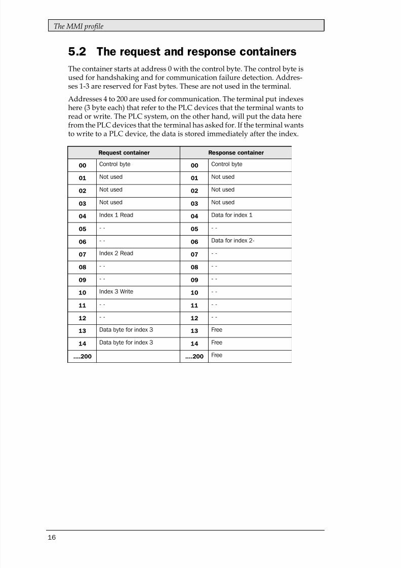
The container starts at address 0 with the control byte. The control byte isused for handshaking and for communication failure detection. Addres-ses 1-3 are reserved for Fast bytes. These are not used in the terminal.
Addresses 4 to 200 are used for communication. The terminal put indexeshere (3 byte each) that refer to the PLC devices that the terminal wants toread or write. The PLC system, on the other hand, will put the data herefrom the PLC devices that the terminal has asked for. If the terminal wantsto write to a PLC device, the data is stored immediately after the index.
8/10/2019 SIMATIC S5 ProfibusDP - Manual Driver MA-00327-A (12.00).PDF
http://slidepdf.com/reader/full/simatic-s5-profibusdp-manual-driver-ma-00327-a-1200pdf 18/49
The MMI profile
17
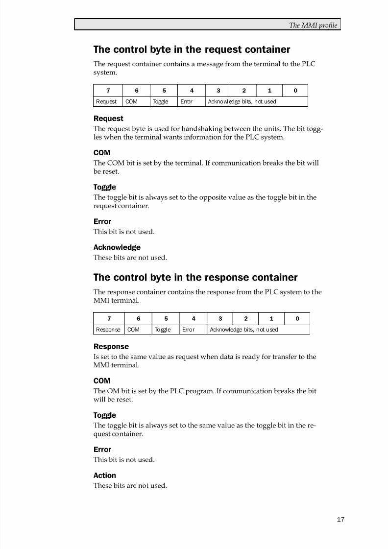
The request container contains a message from the terminal to the PLCsystem.
The request byte is used for handshaking between the units. The bit togg-les when the terminal wants information for the PLC system.
The COM bit is set by the terminal. If communication breaks the bit willbe reset.
The toggle bit is always set to the opposite value as the toggle bit in therequest container.
This bit is not used.
These bits are not used.
The response container contains the response from the PLC system to theMMI terminal.
Is set to the same value as request when data is ready for transfer to theMMI terminal.
The OM bit is set by the PLC program. If communication breaks the bitwill be reset.
The toggle bit is always set to the same value as the toggle bit in the re-quest container.
This bit is not used.
These bits are not used.
8/10/2019 SIMATIC S5 ProfibusDP - Manual Driver MA-00327-A (12.00).PDF
http://slidepdf.com/reader/full/simatic-s5-profibusdp-manual-driver-ma-00327-a-1200pdf 19/49
The MMI profile
18
5.3 The index structure
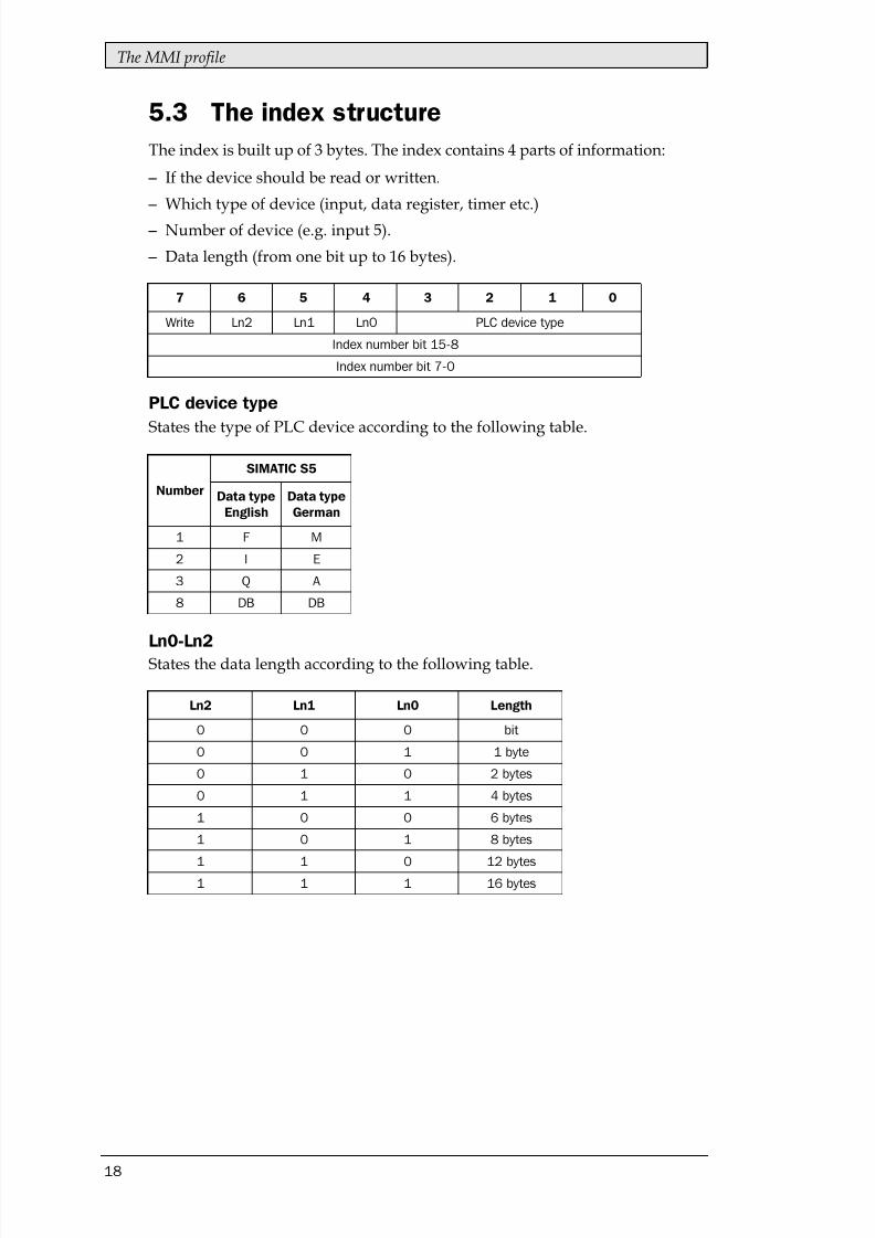
The index is built up of 3 bytes. The index contains 4 parts of information:
– If the device should be read or written.
– Which type of device (input, data register, timer etc.)
– Number of device (e.g. input 5).
– Data length (from one bit up to 16 bytes).
States the type of PLC device according to the following table.
States the data length according to the following table.
8/10/2019 SIMATIC S5 ProfibusDP - Manual Driver MA-00327-A (12.00).PDF
http://slidepdf.com/reader/full/simatic-s5-profibusdp-manual-driver-ma-00327-a-1200pdf 20/49
The MMI profile
19
– The terminal decides which variables are to be read/written.
– The terminal toggles the request flag in the control byte.
– In the next PROFIBUS cycle, the PLC notices that the request flag has
been changed. – For each read index, the values of the requested devices are copied to
the response container.
– Then the response flag in the response container is set to the same valueas the request flag in the request container.
– In the next PROFIBUS cycle, the terminal notices that the request flagand the response flag are the same which means that there is data forthe terminal.
– The received values will now be used by the objects in the terminal.
8/10/2019 SIMATIC S5 ProfibusDP - Manual Driver MA-00327-A (12.00).PDF
http://slidepdf.com/reader/full/simatic-s5-profibusdp-manual-driver-ma-00327-a-1200pdf 21/49
Efficient communication
20
6 Efficient communication
To make the communication between the terminal and the PLC systemquick and efficient the following should be noted about how the signalsare read and what that can be done to optimize the reading.
6.1 Signals affecting the communication
time
It is only signals to objects in the current block that are read continuously.Signals to objects in other blocks are not read, that is the number of blocksdoes not affect the communication time.
Besides the signals to objects in the current block, the terminal is continu-ously reading the following signals from the PLC:
Display signalsBlock print-out signalsLED registersAlarm signalsRemote acknowledge signals on alarms and alarm groupsLogin signalLogout signalTrend registers at the sample pointsBargraph registers if using min/max indicatorsNew display registerBuzzer register
Backlight signalCursor control blockRecipe control blockLibrary index registerIndex registersPLC clock register if the PLC clock is used in the terminalList erase signalNo protocol control registerNo protocol on signal
Signals not affecting the communication time
The following signals do not affect the communication time:
– Signals linked to function keys
– Time channels
– Objects in the alarm messages
8/10/2019 SIMATIC S5 ProfibusDP - Manual Driver MA-00327-A (12.00).PDF
http://slidepdf.com/reader/full/simatic-s5-profibusdp-manual-driver-ma-00327-a-1200pdf 22/49
Efficient communication
21
6.2 How to make the communication more
efficient
Group PLC signals consecutively
The signals from the PLC system are read most rapidly if all signals in thelist above are consecutive. If for example, 100 signals are defined, it isquickest to read these if they are linked to, for example, M0.0-M11.7. If thesignals are spread out (e.g. I0.4, Q30.0, M45.3 etc.) the updating is slower.
Efficient block changes
Block changes are carried out most rapidly and efficiently through theblock jump function on the function keys or through a jump object. "Dis-play signals" in the block header should only be used when the PLC sys-tem is to force the presentation of another block. The "New Display"register can also be used if the PLC system is to change the block. Thisdoes not affect communication as much as a larger number of "Display
signals".
Use the clock of the terminal
An extra load is put on communication if the clock of the PLC system isused since the clock register must be read up to the terminal. Downloa-ding of the clock to the PLC system also creates an extra load. The intervalbetween downloads should therefore be as long as possible.
Packaging of signals
When the signals are transferred between the terminal and the PLC sys-tem, all signals are not transferred simultaneously. Instead they are divi-
ded into packages with a number of signals in each package. To decreasethe number of packages that have to be transferred and make the commu-nication faster this number has to be considered. The number of signals ineach package depends on the used driver. In the SIMATIC S5 Profibus DPdriver the number is 8 for analog devices and 128 for digital devices.
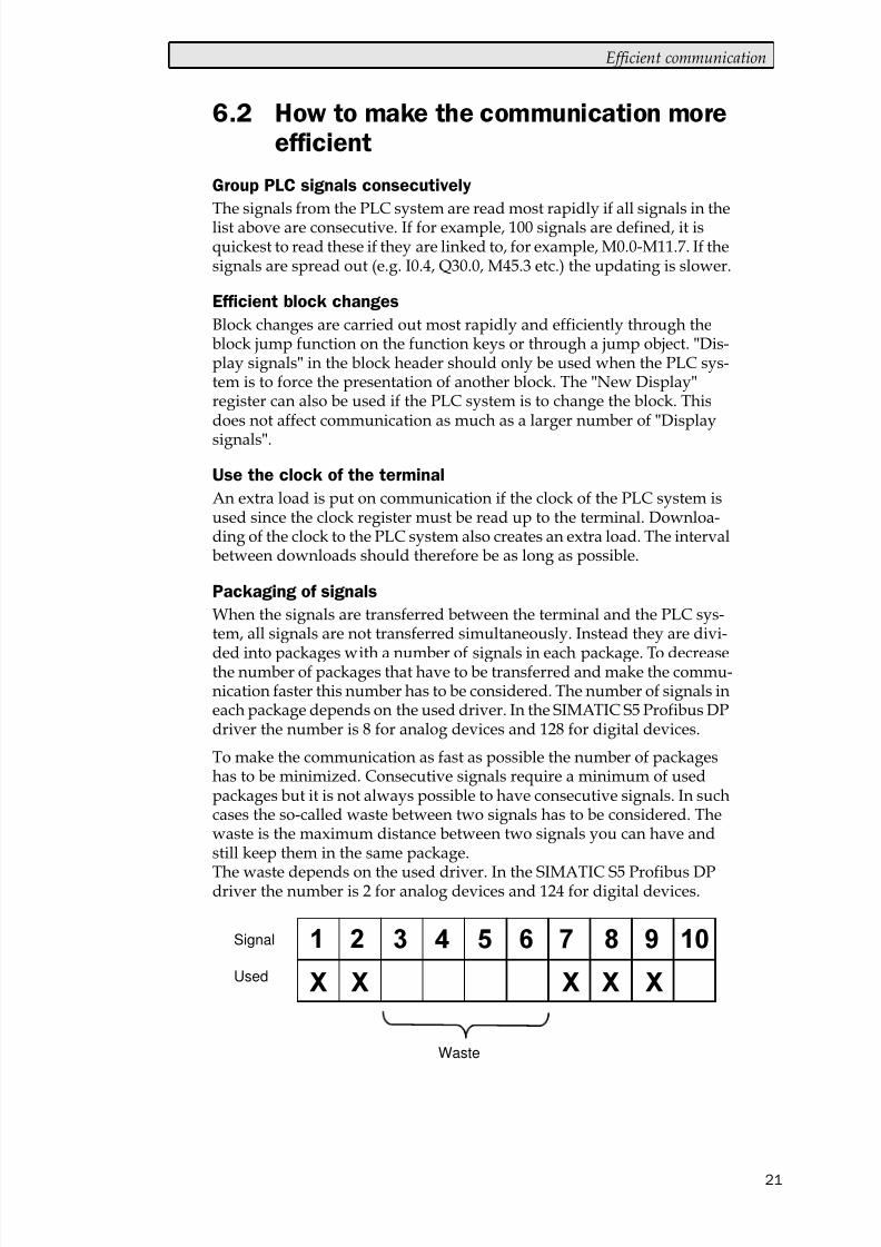
To make the communication as fast as possible the number of packageshas to be minimized. Consecutive signals require a minimum of usedpackages but it is not always possible to have consecutive signals. In suchcases the so-called waste between two signals has to be considered. Thewaste is the maximum distance between two signals you can have andstill keep them in the same package.
The waste depends on the used driver. In the SIMATIC S5 Profibus DPdriver the number is 2 for analog devices and 124 for digital devices.
Signal
Used
Waste
8/10/2019 SIMATIC S5 ProfibusDP - Manual Driver MA-00327-A (12.00).PDF
http://slidepdf.com/reader/full/simatic-s5-profibusdp-manual-driver-ma-00327-a-1200pdf 23/49
Drawings
22
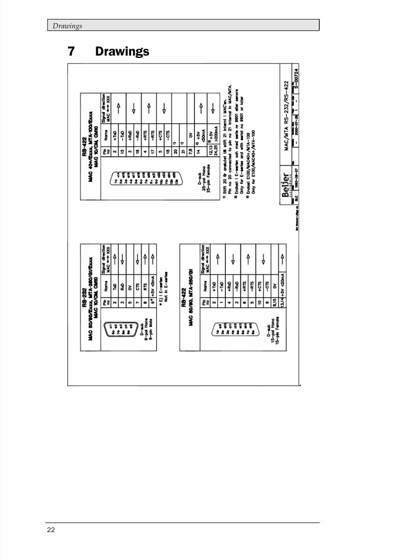
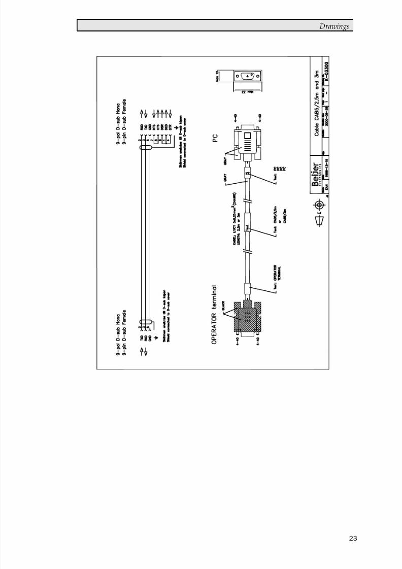
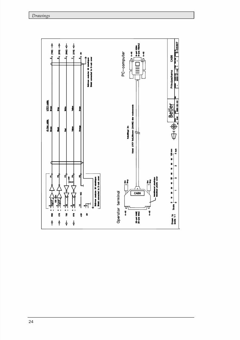
7 Drawings
8/10/2019 SIMATIC S5 ProfibusDP - Manual Driver MA-00327-A (12.00).PDF
http://slidepdf.com/reader/full/simatic-s5-profibusdp-manual-driver-ma-00327-a-1200pdf 24/49
Drawings
23
8/10/2019 SIMATIC S5 ProfibusDP - Manual Driver MA-00327-A (12.00).PDF
http://slidepdf.com/reader/full/simatic-s5-profibusdp-manual-driver-ma-00327-a-1200pdf 25/49
Drawings
24

8/10/2019 SIMATIC S5 ProfibusDP - Manual Driver MA-00327-A (12.00).PDF
http://slidepdf.com/reader/full/simatic-s5-profibusdp-manual-driver-ma-00327-a-1200pdf 26/49
Siemens SIMATIC S5 PROFIBUS DP
Denna manual är en installations- och hanteringsmanual till drivrutinenSIMATIC S5 Profibus DP till operatörsterminalerna i E-serien.Funktionaliteten i terminalerna och i MAC Programmer+ är beskriven iE-seriemanualen.
© Beijer Electronics AB 2000, MA00327A, 2000-12
Beijer Electronics AB reserverar sig mot att informationen i denna manual kan komma attändra sig utan föregående varning. Alla exempel i denna i denna manual används endastför att öka förståelsen om hur programmen arbetar. Beijer Electronics AB tar inget ansvarför att dessa fungerar i verkliga applikationer.
8/10/2019 SIMATIC S5 ProfibusDP - Manual Driver MA-00327-A (12.00).PDF
http://slidepdf.com/reader/full/simatic-s5-profibusdp-manual-driver-ma-00327-a-1200pdf 27/49
Innehåll
Innehåll
1 Introduktion ...........................................................................................3
2 Installation och uppdatering av drivrutin............................................4
2.1 Installation av drivrutin med Internet ..............................................4
2.2 Installation av drivrutin från disk ....................................................4
3 Ansluta terminalen till PLC-systemet ..................................................5
3.1 Inställningar i MAC Programmer+ ..................................................5
3.2 Koppla in terminalen till Profibus DP nätverket ..............................8
3.3 Kommunikationsinställningar för IFC PBDP kortet ........................8
3.4 Kabel till PROFIBUS DP ...................................................................8
3.5 Tekniska data ....................................................................................9
3.6 Beskrivning av PLC-programdelen................................................10
4 Adressering ..........................................................................................13
5 MMI-profilen .......................................................................................15
5.1 Datautbyte ......................................................................................15
5.2 Areorna för begäran och svar .........................................................16
5.3 Strukturen på index ........................................................................18
6 Effektiv kommunikation .....................................................................20
6.1 Signaler som påverkar kommunikationstiden ...............................20
6.2 Hur man kan göra kommunikationen effektivare .........................21
7 Ritningar...............................................................................................22
8/10/2019 SIMATIC S5 ProfibusDP - Manual Driver MA-00327-A (12.00).PDF
http://slidepdf.com/reader/full/simatic-s5-profibusdp-manual-driver-ma-00327-a-1200pdf 28/49
Introduktion
3
1 Introduktion
Manualen beskriver hur SIMATIC S5 PLC-system ansluts till operatörs-terminalerna i E-serien via fältbusen Profibus DP. Adressering iPLC-systemet görs på normalt Siemens sätt. För information omPLC-systemet refereras till manualen för aktuellt system.
Terminalen stöder SIMATIC S5 90, 115, 135 and 155.
Expansionskortet IFC PBDP måste installeras i terminalen.
Se manualen för IFC PBDP.
8/10/2019 SIMATIC S5 ProfibusDP - Manual Driver MA-00327-A (12.00).PDF
http://slidepdf.com/reader/full/simatic-s5-profibusdp-manual-driver-ma-00327-a-1200pdf 29/49
Installation och uppdatering av drivrutin
4
2 Installation och uppdatering av
drivrutin
Tillgängliga drivrutiner installeras samtidigt som MAC Programmer+ in-stalleras. En ny drivrutin kan läggas till i MAC Programmer+ antingenmed hjälp av MAC Programmer+ och en Internet anslutning eller från dis-kett. En drivrutin kan bli uppdaterad till nyare version på samma sätt.
2.1 Installation av drivrutin med Internet
För att uppdatera tillgängliga drivrutiner till senaste version eller för attinstallera nya drivrutiner används funktionen Update terminal drivers,from Internet i menyn File i MAC Programmer+. Alla projekt måste stäng-as innan funktionen används och datorn måste kunna göra en Internet an-
slutning. Någon browser behövs inte. När anslutningen är etablerad visasen lista med alla drivrutiner som kan laddas ner via Internet till datorn. Ilistan visas versionsnummer på tillgängliga drivrutiner och versionsnum-ret på installerade drivrutiner i MAC Programmer+. Markera de drivruti-ner som ska installeras i MAC Programmer+. Funktionen Mark Newermarkerar alla drivrutiner som finns tillgängliga i en senare version och desom inte är installerade. Välj därefter Download. Varje drivrutin är unge-fär 500 kb stor och de är färdiga att använda när nedladdningen är klar.
2.2 Installation av drivrutin från disk
För att uppdatera tillgängliga drivrutiner till senaste version eller för attinstallera nya drivrutiner används funktionen Update terminal drivers,from Disk i menyn File i MAC Programmer+. Alla projekt måste stängasinnan funktionen används. Välj den katalog som innehåller den nya driv-rutinen och välj att öppna mpd-filen. En lista visas med alla drivrutinersom kan installeras. I listan visas versionsnummer på tillgängliga drivru-tiner och versionsnumret på installerade drivrutiner i MAC Program-mer+. Markera de drivrutiner som ska installeras i MAC Programmer+.Funktionen Mark Newer markerar alla drivrutiner som finns tillgängligai en senare version och de som inte är installerade. Välj därefter Install.
Hur man väljer SIMATIC S5 Profibus DP drivrutinen i projektet och hur
man överför den till terminalen beskrivs i kapitel kapitel 3.
8/10/2019 SIMATIC S5 ProfibusDP - Manual Driver MA-00327-A (12.00).PDF
http://slidepdf.com/reader/full/simatic-s5-profibusdp-manual-driver-ma-00327-a-1200pdf 30/49
Ansluta terminalen till PLC-systemet
5
3 Ansluta terminalen till PLC-
systemet
3.1 Inställningar i MAC Programmer+För komunikation med SIMATIC S5 PLC-systemet via fältbussenProfibus DP måste följande inställningar göras i programmerings-verktyget MAC Programmer+.
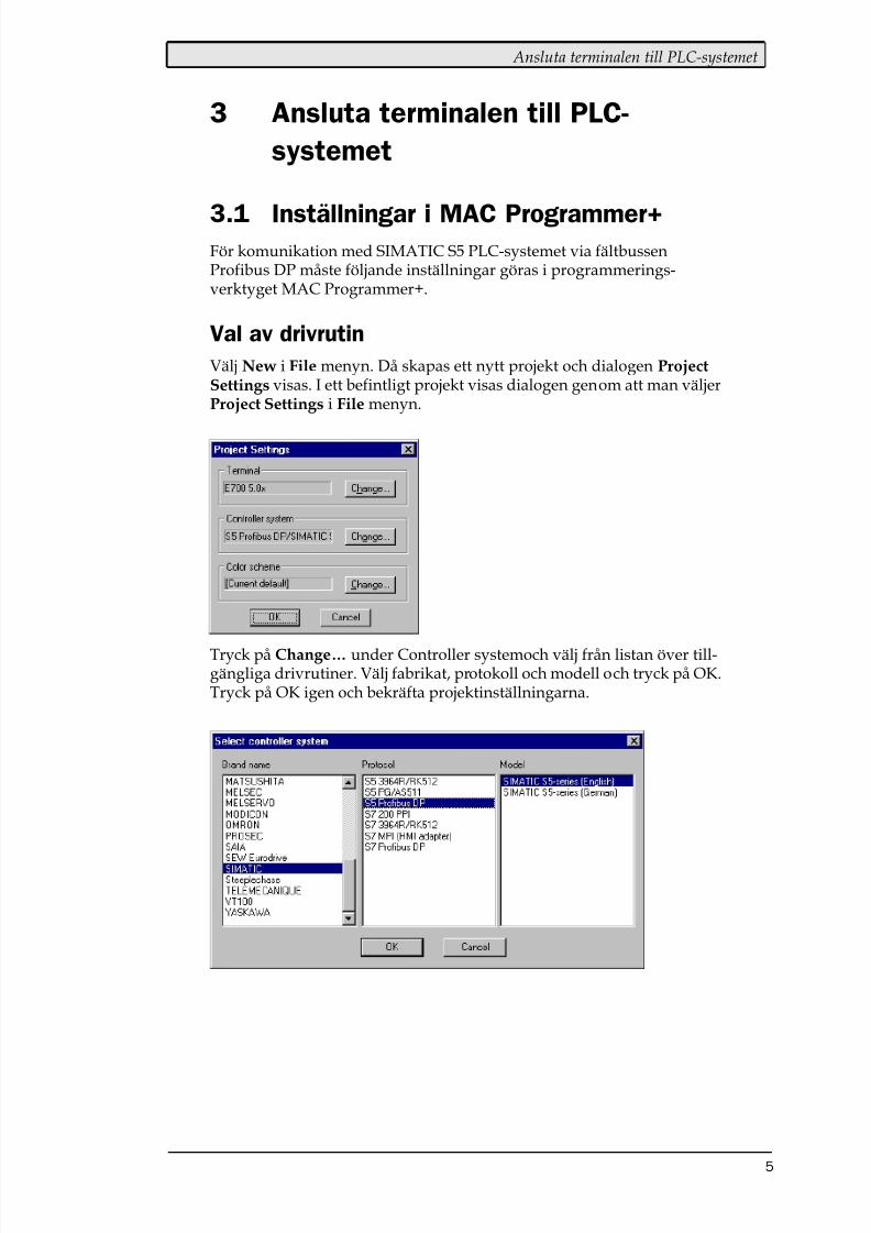
Val av drivrutin
Välj New i File menyn. Då skapas ett nytt projekt och dialogen ProjectSettings visas. I ett befintligt projekt visas dialogen genom att man väljerProject Settings i File menyn.
Tryck på Change… under Controller systemoch välj från listan över till-gängliga drivrutiner. Välj fabrikat, protokoll och modell och tryck på OK.Tryck på OK igen och bekräfta projektinställningarna.
8/10/2019 SIMATIC S5 ProfibusDP - Manual Driver MA-00327-A (12.00).PDF
http://slidepdf.com/reader/full/simatic-s5-profibusdp-manual-driver-ma-00327-a-1200pdf 31/49
Ansluta terminalen till PLC-systemet
6
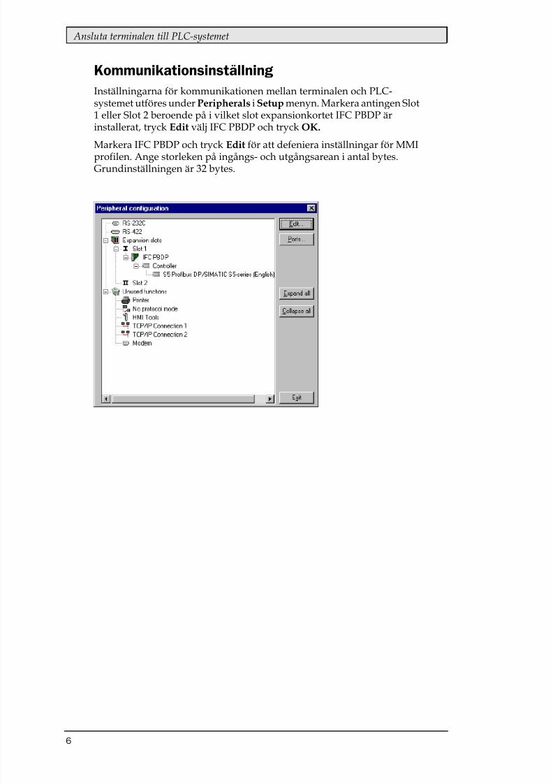
KommunikationsinställningInställningarna för kommunikationen mellan terminalen och PLC-systemet utföres under Peripherals i Setup menyn. Markera antingen Slot1 eller Slot 2 beroende på i vilket slot expansionkortet IFC PBDP ärinstallerat, tryck Edit välj IFC PBDP och tryck OK.
Markera IFC PBDP och tryck Edit för att defeniera inställningar för MMIprofilen. Ange storleken på ingångs- och utgångsarean i antal bytes.Grundinställningen är 32 bytes.
8/10/2019 SIMATIC S5 ProfibusDP - Manual Driver MA-00327-A (12.00).PDF
http://slidepdf.com/reader/full/simatic-s5-profibusdp-manual-driver-ma-00327-a-1200pdf 32/49
Ansluta terminalen till PLC-systemet
7
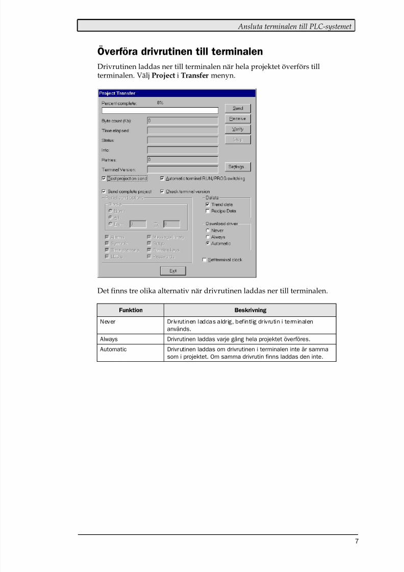
Överföra drivrutinen till terminalenDrivrutinen laddas ner till terminalen när hela projektet överförs tillterminalen. Välj Project i Transfer menyn.
Det finns tre olika alternativ när drivrutinen laddas ner till terminalen.
Funktion Beskrivning
Never Drivrutinen laddas aldrig, befintlig drivrutin i terminalen
används.
Always Drivrutinen laddas varje gång hela projektet överföres.
Automatic Drivrutinen laddas om drivrutinen i terminalen inte är samma
som i projektet. Om samma drivrutin finns laddas den inte.

8/10/2019 SIMATIC S5 ProfibusDP - Manual Driver MA-00327-A (12.00).PDF
http://slidepdf.com/reader/full/simatic-s5-profibusdp-manual-driver-ma-00327-a-1200pdf 33/49
Ansluta terminalen till PLC-systemet
8
3.2 Koppla in terminalen till Profibus DP
nätverketMed expansionskortet IFC PBDP kan terminalen anslutas som en slavnodi ett Profibus DP nätverk. PLC-systemet måste innhålla ett program som
sköter kommunikationen mellan terminalen och PLC-systemet
3.3 Kommunikationsinställningar förIFC PBDP kortet
1. Kontakt för anslutning av kommunikationskabel.
2. Bussterminering. Sätts i läge ON på den första och sista enheten inätverket. Den första enheten i nätverket är oftast masterenheten iPLC-systemet.
3. 1: Röd, ERR, Konfigurerings- eller kommunikationsfel. Lysdioden ärröd tills enheten är konfigurerad. Indikerar time out.2: Grön, PWR, Spänningsmatning, 5 VDC OK.3: Grön, DIA, Diagnostikfel. Används inte.
4. Anger stationsnummer.
3.4 Kabel till PROFIBUS DP
0 01 12 2
3 3
4 5 6
4 5 6
7 7
8 8 9 9
Term Stn no
MS LS
ON
1
1 2 3 4
12
3
(3) RxD/TxD-P
(5) DGND
(8) RxD/TxD-NRxD/TxD-N (8)
DGND (5)
RxD/TxD-P (3)
Jord
Skärm
Jord
Station 2Station 1
8/10/2019 SIMATIC S5 ProfibusDP - Manual Driver MA-00327-A (12.00).PDF
http://slidepdf.com/reader/full/simatic-s5-profibusdp-manual-driver-ma-00327-a-1200pdf 34/49
Ansluta terminalen till PLC-systemet
9
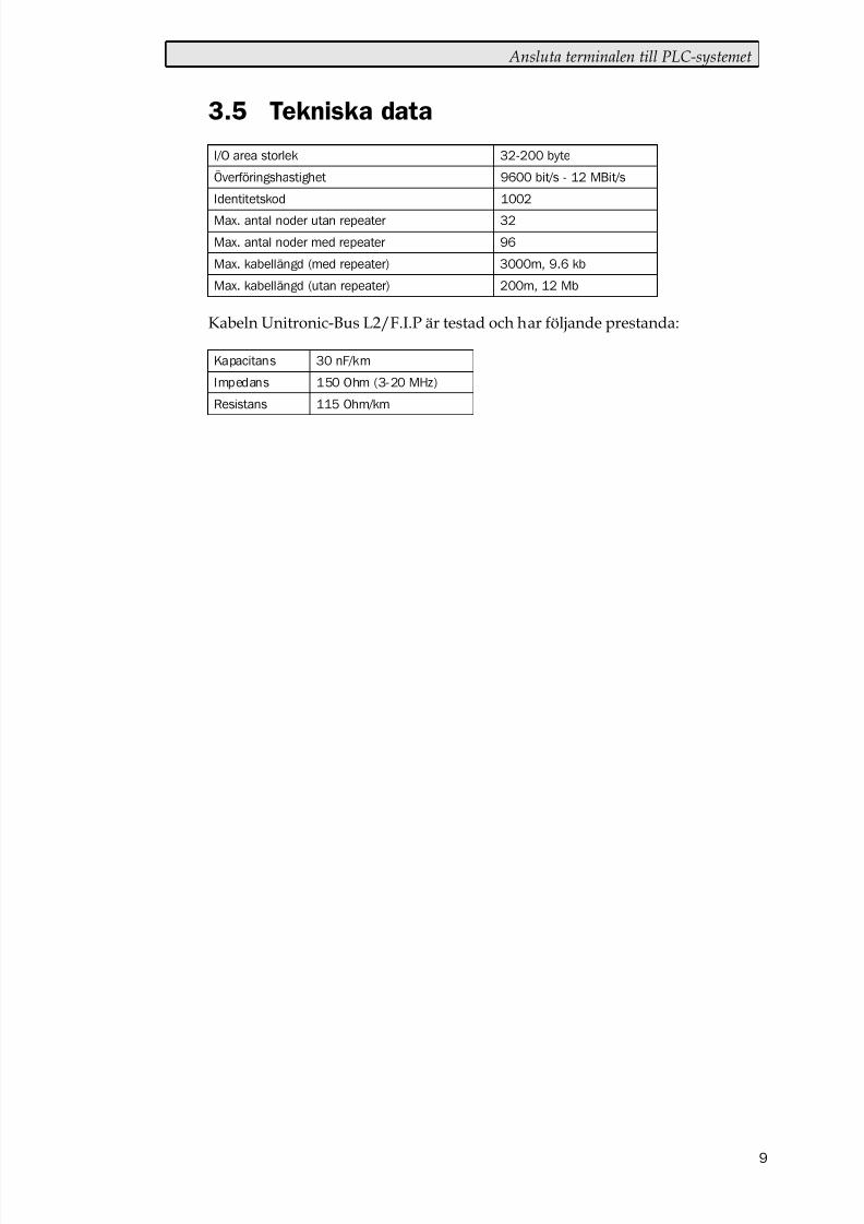
3.5 Tekniska data
Kabeln Unitronic-Bus L2/F.I.P är testad och har följande prestanda:
8/10/2019 SIMATIC S5 ProfibusDP - Manual Driver MA-00327-A (12.00).PDF
http://slidepdf.com/reader/full/simatic-s5-profibusdp-manual-driver-ma-00327-a-1200pdf 35/49
Ansluta terminalen till PLC-systemet
10
3.6 Beskrivning av PLC-programdelen
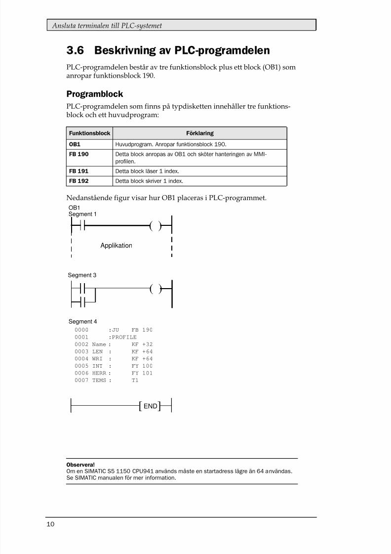
PLC-programdelen består av tre funktionsblock plus ett block (OB1) somanropar funktionsblock 190.
ProgramblockPLC-programdelen som finns på typdisketten innehåller tre funktions-block och ett huvudprogram:
Nedanstående figur visar hur OB1 placeras i PLC-programmet.
Observera!Om en SIMATIC S5 1150 CPU941 används måste en startadress lägre än 64 användas.Se SIMATIC manualen för mer information.
( )
( )
][ END
Applikation
Segment 1
Segment 3
Segment 4
0000 :JU FB 190
0001 :PROFILE
0002 Name : KF +32
0003 LEN : KF +64
0004 WRI : KF +64
0005 INT : FY 100
0006 HERR : FY 101
0007 TEMS : T1
OB1
8/10/2019 SIMATIC S5 ProfibusDP - Manual Driver MA-00327-A (12.00).PDF
http://slidepdf.com/reader/full/simatic-s5-profibusdp-manual-driver-ma-00327-a-1200pdf 36/49
Ansluta terminalen till PLC-systemet
11
Huvudprogrammet, OB1
OB1 är huvudprogrammet där parametrar definieras för anrop av övrigafunktionsblock. Följande parametrar definieras för funktionsblocket 190:
För mer information hänvisas till Siemens manual för SIMATIC S5.
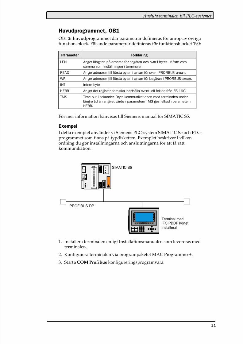
Exempel
I detta exemplet använder vi Siemens PLC-system SIMATIC S5 och PLC-programmet som finns på typdisketten. Exemplet beskriver i vilkenordning du gör inställningarna och anslutningarna för att få rättkommunikation.
1. Installera terminalen enligt Installationsmanualen som levereras medterminalen.
2. Konfigurera terminalen via programpaketet MAC Programmer+.
3. Starta COM Profibus konfigureringsprogramvara.
Terminal medIFC PBDP kortet
SIMATIC S5
PROFIBUS DP
installerat
8/10/2019 SIMATIC S5 ProfibusDP - Manual Driver MA-00327-A (12.00).PDF
http://slidepdf.com/reader/full/simatic-s5-profibusdp-manual-driver-ma-00327-a-1200pdf 37/49
Ansluta terminalen till PLC-systemet
12
4. Konfigurera mastern, överföringshastighet, stationsnummer, antalbytes i överföringsarean etc. För mer information hänvisas tillmanualen för programvaran. Typfiler för terminalen finns på IFCPBDP disketten.
5. Skicka ner konfigurationen till S5. Se Siemens manual för S5.
6. Skicka ner medföljande PLC-programdel till S5.
7. Anslut kabeln mellan S5 systemet och IFC PBDP kortet i terminalen.
8. Sätt PLC-systemet och MMI-terminalen i driftläge.
Observera!Försöker du öppna ett datablock som inte finns stannar PLC-systemet. För mer infor-mation hänvisas till SIMATIC manualen.
8/10/2019 SIMATIC S5 ProfibusDP - Manual Driver MA-00327-A (12.00).PDF
http://slidepdf.com/reader/full/simatic-s5-profibusdp-manual-driver-ma-00327-a-1200pdf 38/49
Adressering
13
4 Adressering
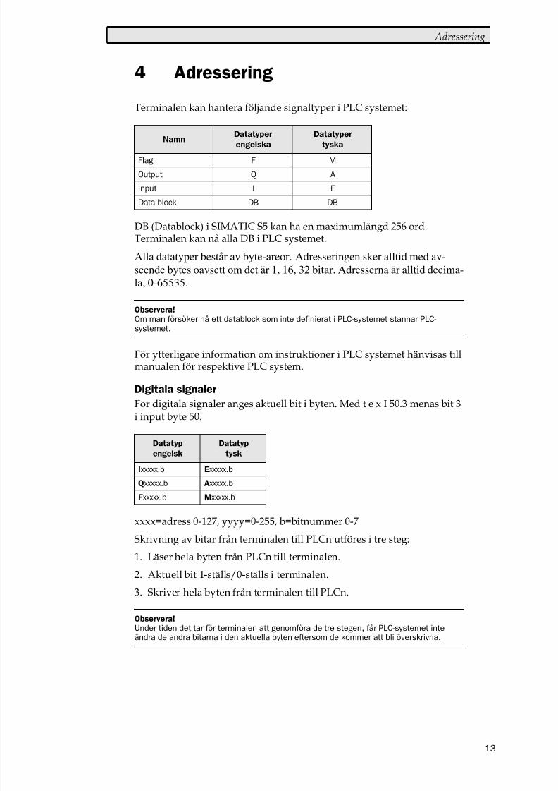
Terminalen kan hantera följande signaltyper i PLC systemet:
DB (Datablock) i SIMATIC S5 kan ha en maximumlängd 256 ord.Terminalen kan nå alla DB i PLC systemet.
Alla datatyper består av byte-areor. Adresseringen sker alltid med av-seende bytes oavsett om det är 1, 16, 32 bitar. Adresserna är alltid decima-la, 0-65535.
För ytterligare information om instruktioner i PLC systemet hänvisas tillmanualen för respektive PLC system.
Digitala signaler
För digitala signaler anges aktuell bit i byten. Med t e x I 50.3 menas bit 3
i input byte 50.
xxxx=adress 0-127, yyyy=0-255, b=bitnummer 0-7
Skrivning av bitar från terminalen till PLCn utföres i tre steg:
1. Läser hela byten från PLCn till terminalen.
2. Aktuell bit 1-ställs/0-ställs i terminalen.
3. Skriver hela byten från terminalen till PLCn.
Observera!Om man försöker nå ett datablock som inte definierat i PLC-systemet stannar PLC-systemet.
Datatyp
engelsk
Datatyp
tysk
Observera!Under tiden det tar för terminalen att genomföra de tre stegen, får PLC-systemet inteändra de andra bitarna i den aktuella byten eftersom de kommer att bli överskrivna.
8/10/2019 SIMATIC S5 ProfibusDP - Manual Driver MA-00327-A (12.00).PDF
http://slidepdf.com/reader/full/simatic-s5-profibusdp-manual-driver-ma-00327-a-1200pdf 39/49
Adressering
14
Analoga signaler
För 16-bitars tal, anges suffixet W; t ex MW100 betyder 2 bytes frånminnesbyte 100-101.
xxxx=adress 0-126, yyyy=0-254, no=databasnummer 0-255 ochadr=dataord inom databasen 0-255.
För 32-bitars ord, anges suffixet D; t ex MD100 betyder 4 bytes från min-nesbyten 100-103.
xxxx=adress 0-124, yyyy=0-252, no=databas nummer 0-255 ochadr=dataord inom databasen 0-254.
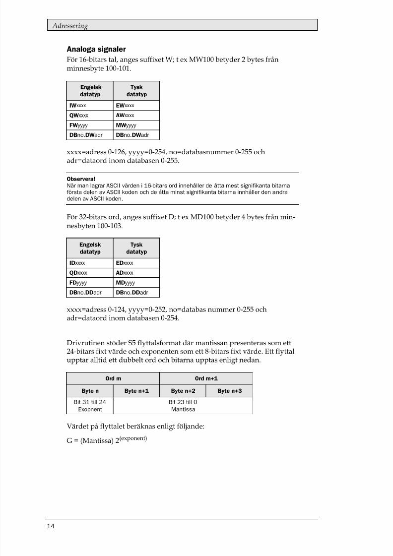
Drivrutinen stöder S5 flyttalsformat där mantissan presenteras som ett24-bitars fixt värde och exponenten som ett 8-bitars fixt värde. Ett flyttalupptar alltid ett dubbelt ord och bitarna upptas enligt nedan.
Värdet på flyttalet beräknas enligt följande:
G = (Mantissa) 2(exponent)
Engelsk
datatyp
Tysk
datatyp
Observera!När man lagrar ASCII värden i 16-bitars ord innehåller de åtta mest signifikanta bitarna
första delen av ASCII koden och de åtta minst signifikanta bitarna innhåller den andradelen av ASCII koden.
Ord m Ord m+1
Byte n Byte n+1 Byte n+2 Byte n+3
Bit 31 till 24
Exopnent
Bit 23 till 0
Mantissa
8/10/2019 SIMATIC S5 ProfibusDP - Manual Driver MA-00327-A (12.00).PDF
http://slidepdf.com/reader/full/simatic-s5-profibusdp-manual-driver-ma-00327-a-1200pdf 40/49
MMI-profilen
15
5 MMI-profilen
Detta kapitlet beskriver hur MMI-profilen är uppbyggd och är riktad tillde användare som vill veta lite mer om datautbyte via MMI-profilen.
MMI-profilen tillåter utbyte av obegränsat antal data. Dessutom tillåterden terminalen att accessa alla datatyper i PLC-systemet.
Tillsammans med kortet levereras en typdiskett som innehåller PLC-programdelar för kommunikation med olika PLC-system.
PROFIBUS-DP tillåter max byte längd på 200 bytes in och 200 bytes ut perstation. MMI-profilen använder en area för begäran och en area för svar.Areorna används för att accessa PLC-systemet.
För mer information om MMI-profilen hänvisas till specifikationer frånthe Profibus Organisation.
5.1 Datautbyte
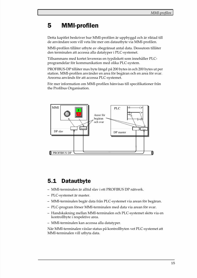
– MMI-terminalen är alltid slav i ett PROFIBUS DP nätverk.
– PLC-systemet är master.
– MMI-terminalen begär data från PLC-systemet via arean för begäran.
– PLC-program förser MMI-terminalen med data via arean för svar.
– Handskakning mellan MMI-terminalen och PLC-systemet sköts via enkontrollbyte i respektive area.
– MMI-terminalen kan accessa alla datatyper.
När MMI-terminalen växlar status på kontrollbyten vet PLC-systemet attMMI-terminalen vill utbyta data.
PLCMMI ()
()
][END
PROFIBUS DP
DP slav DP master
SvarBegäran
Areor förbegäranoch svar
8/10/2019 SIMATIC S5 ProfibusDP - Manual Driver MA-00327-A (12.00).PDF
http://slidepdf.com/reader/full/simatic-s5-profibusdp-manual-driver-ma-00327-a-1200pdf 41/49
MMI-profilen
16
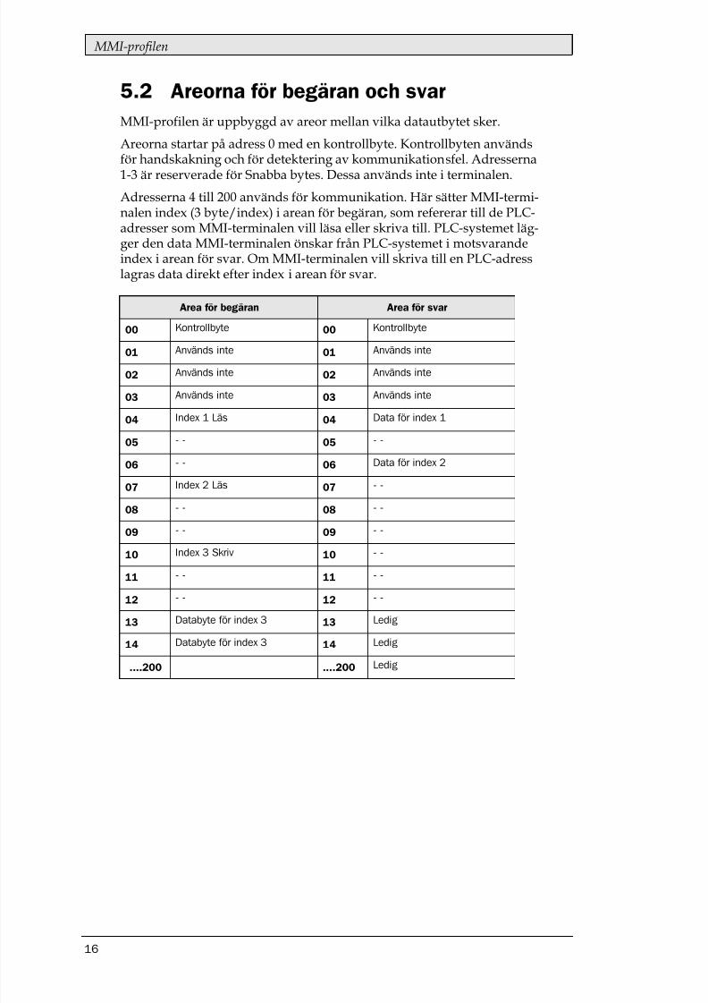
5.2 Areorna för begäran och svarMMI-profilen är uppbyggd av areor mellan vilka datautbytet sker.
Areorna startar på adress 0 med en kontrollbyte. Kontrollbyten användsför handskakning och för detektering av kommunikationsfel. Adresserna
1-3 är reserverade för Snabba bytes. Dessa används inte i terminalen.Adresserna 4 till 200 används för kommunikation. Här sätter MMI-termi-nalen index (3 byte/index) i arean för begäran, som refererar till de PLC-adresser som MMI-terminalen vill läsa eller skriva till. PLC-systemet läg-ger den data MMI-terminalen önskar från PLC-systemet i motsvarandeindex i arean för svar. Om MMI-terminalen vill skriva till en PLC-adresslagras data direkt efter index i arean för svar.
Area för begäran Area för svar
8/10/2019 SIMATIC S5 ProfibusDP - Manual Driver MA-00327-A (12.00).PDF
http://slidepdf.com/reader/full/simatic-s5-profibusdp-manual-driver-ma-00327-a-1200pdf 42/49
MMI-profilen
17
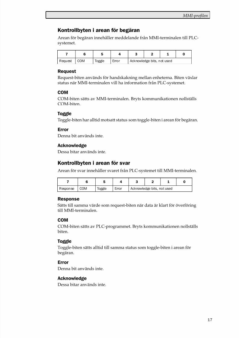
Kontrollbyten i arean för begäranArean för begäran innehåller meddelande från MMI-terminalen till PLC-systemet.
Request-biten används för handskakning mellan enheterna. Biten växlarstatus när MMI-terminalen vill ha information från PLC-systemet.
COM-biten sätts av MMI-terminalen. Bryts kommunikationen nollställsCOM-biten.
Toggle-biten har alltid motsatt status som toggle-biten i arean för begäran.
Denna bit används inte.
Dessa bitar används inte.
Kontrollbyten i arean för svarArean för svar innehåller svaret från PLC-systemet till MMI-terminalen.
Sätts till samma värde som request-biten när data är klart för överföringtill MMI-terminalen.
COM-biten sätts av PLC-programmet. Bryts kommunikationen nollställsbiten.
Toggle-biten sätts alltid till samma status som toggle-biten i arean förbegäran.
Denna bit används inte.
Dessa bitar används inte.
8/10/2019 SIMATIC S5 ProfibusDP - Manual Driver MA-00327-A (12.00).PDF
http://slidepdf.com/reader/full/simatic-s5-profibusdp-manual-driver-ma-00327-a-1200pdf 43/49
MMI-profilen
18
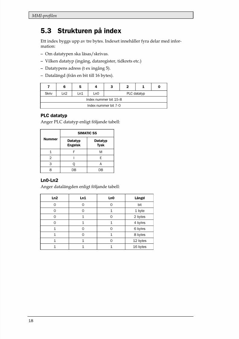
5.3 Strukturen på indexEtt index byggs upp av tre bytes. Indexet innehåller fyra delar med infor-mation:
– Om datatypen ska läsas/skrivas.
– Vilken datatyp (ingång, dataregister, tidkrets etc.)
– Datatypens adress (t ex ingång 5).
– Datalängd (från en bit till 16 bytes).
Anger PLC datatyp enligt följande tabell:
Anger datalängden enligt följande tabell:

8/10/2019 SIMATIC S5 ProfibusDP - Manual Driver MA-00327-A (12.00).PDF
http://slidepdf.com/reader/full/simatic-s5-profibusdp-manual-driver-ma-00327-a-1200pdf 44/49
MMI-profilen
19
– MMI-terminalen bestämmer vilken variabel som ska läsas/skrivas.
– Terminalen växlar status på request flaggan i kontrollbyten.
– Nästa PROFIBUS cykel upptäcker PLC-systemet att request-
flaggan har ändrats. – För varje läsindex kopieras värdet i den begärda datatyper till arean för
svar.
– Därefter sätts response-flaggan i arean för svar till samma värde somrequest-flaggan i arean för begäran.
– Nästa PROFIBUS cykel upptäcker MMI-terminalen att request-flagganoch response-flaggan har samma värde vilket betyder att det finns datatill terminalen.
– De mottagna värdena kommer nu att användas av objekten iterminalen.
8/10/2019 SIMATIC S5 ProfibusDP - Manual Driver MA-00327-A (12.00).PDF
http://slidepdf.com/reader/full/simatic-s5-profibusdp-manual-driver-ma-00327-a-1200pdf 45/49
Effektiv kommunikation
20
6 Effektiv kommunikation
För att göra kommunikationen mellan terminalen och PLC systemetsnabb och effektiv bör följande noteras om hur signalerna läses och vadsom kan göras för att optimera detta.
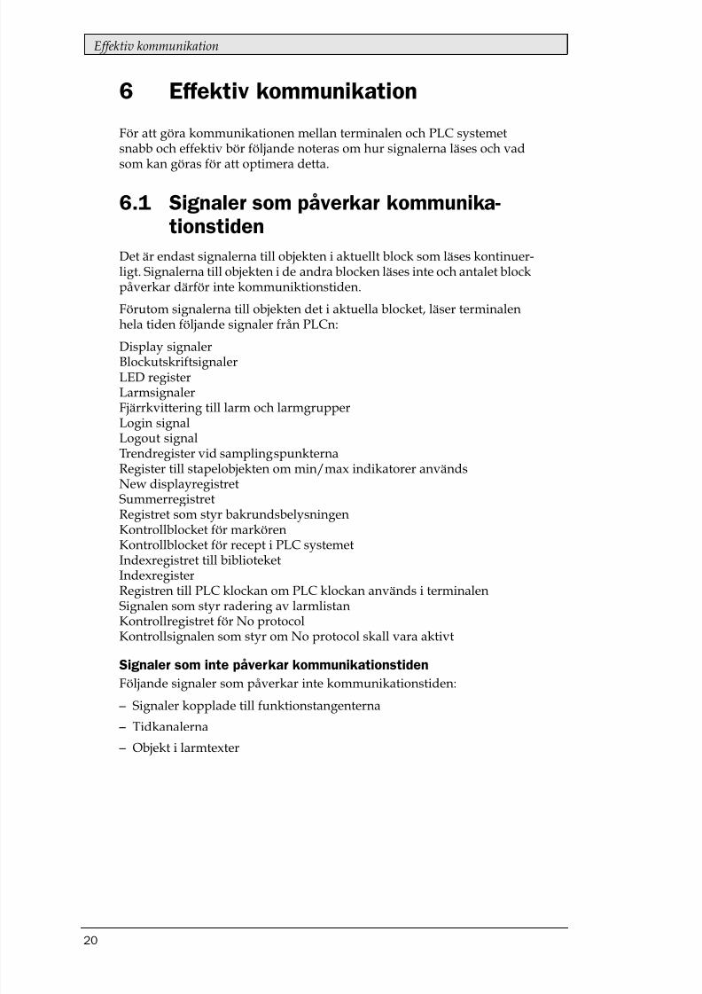
6.1 Signaler som påverkar kommunika-tionstiden
Det är endast signalerna till objekten i aktuellt block som läses kontinuer-ligt. Signalerna till objekten i de andra blocken läses inte och antalet blockpåverkar därför inte kommuniktionstiden.
Förutom signalerna till objekten det i aktuella blocket, läser terminalenhela tiden följande signaler från PLCn:
Display signalerBlockutskriftsignalerLED registerLarmsignalerFjärrkvittering till larm och larmgrupperLogin signalLogout signalTrendregister vid samplingspunkternaRegister till stapelobjekten om min/max indikatorer användsNew displayregistretSummerregistretRegistret som styr bakrundsbelysningenKontrollblocket för markörenKontrollblocket för recept i PLC systemetIndexregistret till biblioteketIndexregisterRegistren till PLC klockan om PLC klockan används i terminalenSignalen som styr radering av larmlistanKontrollregistret för No protocolKontrollsignalen som styr om No protocol skall vara aktivt
Signaler som inte påverkar kommunikationstidenFöljande signaler som påverkar inte kommunikationstiden:
– Signaler kopplade till funktionstangenterna
– Tidkanalerna
– Objekt i larmtexter
8/10/2019 SIMATIC S5 ProfibusDP - Manual Driver MA-00327-A (12.00).PDF
http://slidepdf.com/reader/full/simatic-s5-profibusdp-manual-driver-ma-00327-a-1200pdf 46/49
Effektiv kommunikation
21
6.2 Hur man kan göra kommunikationeneffektivare
Gruppera PLC-signalerna i en följdSignalerna från PLC systemet läses snabbast om signalerna i listan ovanär i en följd. Till exempel om 100 signaler är definerade, läses dessa snab-bast om de grupperas, till exempel M0.0-M11.7. Om signalerna sprides ut(t ex I0.4, Q30.0, M45.3 etc.) går uppdateringen långsammare.
Effektiva blockbyten
Blockbyte sker effektivas via blockhoppsfunktionen på funktionstang-entrna eller via hoppobjekt. "Display signals" i blockhuvudet bör endastanvändas då PLC systemet ska tvinga fram en annat block. Ska PLC-sys-temet byta bild kan även "New Display" -registret användas. Det belastarinte kommunikationen lika mycket som ett större antal "Display signals".
Använd klockan i terminalenAnvänds terminalklockan belastas kommunikationen eftersom PLC-sys-temets klockregister måste läsas upp till terminalen. Nerladdningen avterminalklockan till PLC-systemet belastar också.Intervallet mellan nerladdningarna bör därför vara så långt som möjligt.
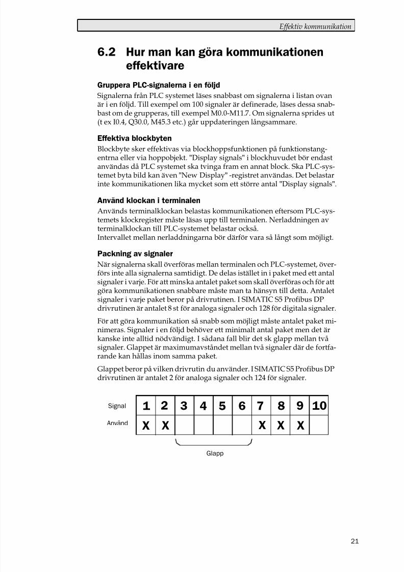
Packning av signaler
När signalerna skall överföras mellan terminalen och PLC-systemet, över-förs inte alla signalerna samtidigt. De delas istället in i paket med ett antalsignaler i varje. För att minska antalet paket som skall överföras och för attgöra kommunikationen snabbare måste man ta hänsyn till detta. Antalet
signaler i varje paket beror på drivrutinen. I SIMATIC S5 Profibus DPdrivrutinen är antalet 8 st för analoga signaler och 128 för digitala signaler.
För att göra kommunikation så snabb som möjligt måste antalet paket mi-nimeras. Signaler i en följd behöver ett minimalt antal paket men det ärkanske inte alltid nödvändigt. I sådana fall blir det sk glapp mellan tvåsignaler. Glappet är maximumavståndet mellan två signaler där de fortfa-rande kan hållas inom samma paket.
Glappet beror på vilken drivrutin du använder. I SIMATIC S5 Profibus DPdrivrutinen är antalet 2 för analoga signaler och 124 för signaler.
1 2 3 4 5 6 7 8 9 10
X X X X X
Glapp
Använd
Signal

8/10/2019 SIMATIC S5 ProfibusDP - Manual Driver MA-00327-A (12.00).PDF
http://slidepdf.com/reader/full/simatic-s5-profibusdp-manual-driver-ma-00327-a-1200pdf 47/49
Ritningar
22
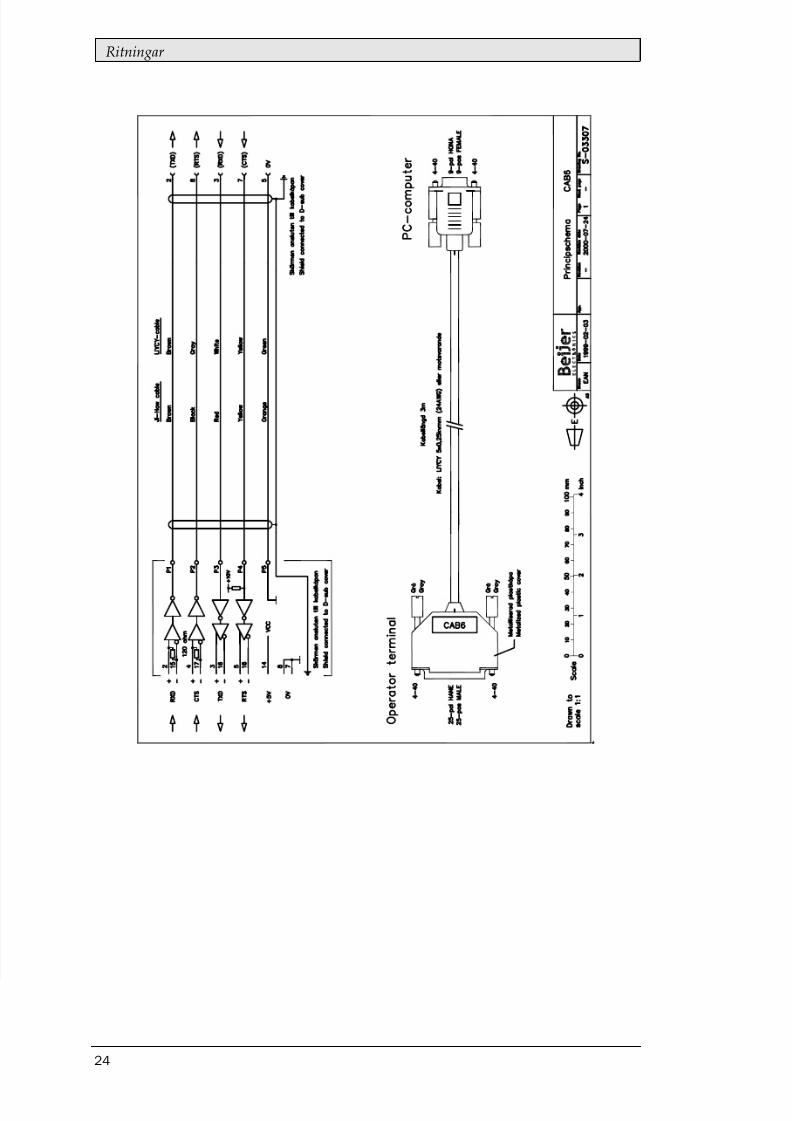
7 Ritningar
8/10/2019 SIMATIC S5 ProfibusDP - Manual Driver MA-00327-A (12.00).PDF
http://slidepdf.com/reader/full/simatic-s5-profibusdp-manual-driver-ma-00327-a-1200pdf 48/49
Ritningar
23
8/10/2019 SIMATIC S5 ProfibusDP - Manual Driver MA-00327-A (12.00).PDF
http://slidepdf.com/reader/full/simatic-s5-profibusdp-manual-driver-ma-00327-a-1200pdf 49/49
Ritningar