simotics sd – 1le5 - cache.industry.siemens.com · simotics sd – 1le5 355 - 1000 kw ... step 6...
TRANSCRIPT

Page 2/1 Siemens D 81.1 AO · 03/2018
Motors
Low-Voltage Motors
SIMOTICS SD – 1LE5 355 - 1000 kW
www.siemens.com/simotics
Catalog Add-on D 81.1 AO
Edition 03/2018
© Siemens AG 2018
Low-Voltage Motors SIMOTICS SD – 1LE5
Motors Introduction General Information regarding efficiency in accordance with International Efficiency, Guide to selection and ordering the motors, General technical specifications
SIMOTICS SD Stndard Motors next generation 1LE5
Catalog D 81.1 AO · 04/2018 For reasons of readability, the chapter Intro-duction generally refers to motors and does not mention the MLFB fuselage. In this catalogue Add-on D81.1 AO the term motors refers to SIMOTICS SD next generation, Series 1LE5 frame sizes 400 and 450.
The products and systems described in this catalog are manufactured/distributed under application of a certified quality management system in accordance with EN ISO 9001 Certified Registration No. DE-000357 QM) The certificate is recognized by all IQNet countries.
1
2
Introduction
1/16
11/2 Guide to selecting and
ordering motors 1/3 Catalog orientation and drive selection
1/4 General information 1/4 Colors and paint finish
1/7 Electrical design
1/7 Rating plate and additional rating plates
1/8 Converter operation
1/9 Windings and insulation
1/11 Coolant temperature and installation altitude
1/12 Heating and ventilation
1/13 Connection, circuit, and terminal boxes
1/16 Mechanical design 1/16 Types of construction
1/16 Flange dimensions
1/17 Bearings and lubrication
Introduction
Page 1/2 Siemens D 81.1 AO · 03/2018
Guide to selecting and ordering motors
■ Overview
Steps for drive selection
Catalog orientation and drive selection
Select the frame size and therefore the possible motors on the basis of the following parameters: cooling method, degree of protection, rated power, rated speed and rated torque range. Note: The standard temperature range of the motors is from -20 to +40 °C.
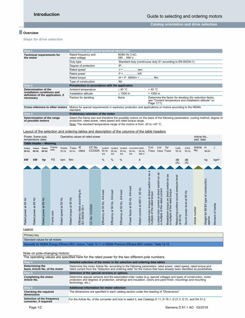
Layout of the selection and ordering tables and description of the columns of the table headers
Legend:
Primary key
Standard values for all motors
Specially for NEMA Energy Efficient MG1 motors, Table 12-11 or NEMA Premium Efficient MG1 motors, Table 12-12
Note on pole-changing motors: The operating values are specified here for the rated power for the two different pole numbers.
Power, frame size, temperature class Table header – Meaning
Operating values at rated power Article No., add. data
Prated, Prated, Prated,
50 Hz 60 Hz 60 Hz
Frame size
nrated, 50 Hz
Trated, 50 Hz
IE CC No. rated, class CC032A 50 Hz,
rated, 50 Hz, 3/4
rated, 50 Hz, 2/4
cosrated,Irated,
50 Hz, 4/4
50 Hz, 400 V
TLR/ ILR/ TB/ Trated Irated Trated
LpfA, 50 Hz
LWA, 50 Hz
Article m JNo. IM B3
4/4
kW kW hp FS rpm Nm % % % A dB (A)
dB (A)
kg kgm2
Rat
ed p
ower
at 5
0 H
z
Rat
ed p
ower
at 6
0 H
z
Rat
ed p
ower
at 6
0 H
z
Fra
me
size
Rat
ed s
peed
at
50 H
z
Rat
ed to
rque
at
50 H
z
Eff
icie
ncy
clas
s ac
cord
ing
to
IEC
600
34-3
0-1
CC
No.
CC
032
A
Effi
cien
cy a
t 50
Hz,
4/4
-load
Effi
cien
cy a
t 50
Hz,
3/4
-load
Effi
cien
cy a
t 50
Hz,
2/4
-load
Pow
er f
acto
r at
50
Hz,
4/4
-load
Rat
ed c
urre
nt a
t 400
V,
50 H
z
Lock
ed-r
otor
tor
que
at d
irect
sw
itch-
on a
s a
mul
tiple
of
the
rate
d to
rque
Lock
ed-r
otor
cur
rent
at d
irect
sw
itch-
on a
s a
mul
tiple
of t
he r
ated
cur
rent
Bre
akdo
wn
torq
ue o
n di
rect
sw
itch-
on a
s a
mul
tiple
of t
he r
ated
tor
que
Mea
surin
g-su
rfac
e so
und
pres
sure
leve
l at
50
Hz
Sou
nd p
ower
leve
l at
50 H
z
Art
icle
num
ber
Wei
ght f
or IM
B3
type
of c
onst
ruct
ion,
ap
prox
.
Mom
ent
of in
ertia
Step 1 Orientation and general technical information
Technical requirements for the motor
Rated frequency and 50/60 Hz 3 AC, rated voltage 380 … 690 V
Duty type Standard duty (continuous duty S1 according to EN 60034-1)
Degree of protection IP.. Rated speed n = ................. rpm
Rated power P = ................. kW
Rated torque M = P 9550/n = ................. Nm
Type of construction IM.. Step 2 Preselection in accordance with the application
Determination of the installation conditions and definition of the application, if necessary
Ambient temperature 40 °C > 40 °C
Installation altitude 1000 m > 1000 m
Factors for derating None Determine the factor for derating (for reduction factor, see "Coolant temperature and installation altitude" on Page 1/11)
Cross-reference to other motors Motors for special requirements in explosion protection and applications or motors according to the NEMA standard.
Step 3 Preliminary selection of the motor
Determination of the range of possible motors
Step 4 Detailed selection of the motor in the selection and ordering data tables Determining the basic Article No. of the motor
Determine the motor Article No. according to the following parameters: rated power, rated speed, rated torque and rated current from the "Selection and ordering data" for the motors that have already been identified as possibilities.
Step 5 Selection of the special versions or options
Completing the motor Article No.
Determine special versions and the associated order codes (e.g. special voltages and types of construction, motor protection and degrees of protection, windings and insulation, colors and paint finish, mountings and mounting technology, etc.).
Step 6 Additional information for motor selection
Checking the required dimensions
The dimensions are specified in each catalog section under the heading of "Dimensions".
Selection of the frequency converter, if required
For the Article No. of the converter and how to select it, see Catalogs D 11, D 18.1, D 21.3, D 31, and DA 51.2.
Catalog orientation and drive selection
Introduction Guide to selecting and ordering motors
Siemens D 81.1 AO · 03/2018 Page 1/3
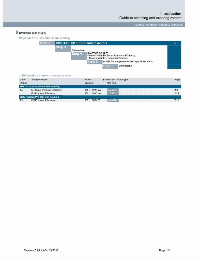
■ Overview (continued)
Steps for drive selection in the catalog
1LE5 standard motors – next generation
Motor Efficiency class Rated Frame size – Motor type Page
version power at 400 450
SIMOTICS SD Add cast-iron housing
IEC IE4 Super Premium Efficiency 355 … 1000 kW 1LE5534 2/9
IE3 Premium Efficiency 355 … 1000 kW 1LE5533 2/11
SIMOTICS SD Pro cast-iron housing IEC IE3 Premium Efficiency 335 … 980 kW 1LE5583 2/13
Step 2 SIMOTICS SD 1LE5 standard motors
Step 3 3
Orientation
Step 4 SIMOTICS SD 1LE5 Motors with IE4 Super Premium Efficiency Motors with IE3 Premium Efficiency
Step 5 Article No. supplements and special versions
Step 6 Dimensions
Introduction General information
Page 1/4 Siemens D 81.1 AO · 03/2018
General information
■ Overview (continued)
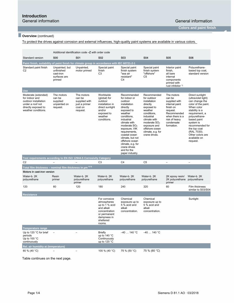
Colors and paint finish
1 To protect the drives against corrosion and external influences, high-quality paint systems are available in various colors.
Additional identification code –Z with order code
Standard version S00 S01 S02 S03 S04 S05 S06
Paint finish, suitability of paint finish for climate group in accordance with IEC 60721-2-1
Standard paint finish C2
Unpainted, but unfinished cast-iron surfaces are primed
Unpainted, motor primed
Special paint finish C3
Special paint finish system "sea air resistant" C4
Special paint finish system "offshore" C5
Interior paint finish, all bare internal components primed with rust inhibitor 1)
Polyurethane-based top coat, standard version
Use
Moderate (extended) for indoor and outdoor installation under a roof not directly exposed to weather conditions.
The motors can be supplied unpainted on request.
The motors can be supplied with just a primer coat on request.
Worldwide (global) for outdoor installation in direct sunlight and/or exposed to weather conditions.
Recommended for indoor or outdoor installation directly exposed to weather conditions, industrial climate with moderate SO2 exposure, VIK requirements, coastal ocean climate, but not offshore ocean climate, e.g. for crane drives and for the paper industry.
Recommended for outdoor installation directly exposed to weather conditions, industrial climate with moderate SO2 exposure and offshore ocean climate, e.g. for crane drives.
The motors can be supplied with internal paint finish on request. Recommended when there is a risk of heavy condensate formation.
Direct sunlight (ultraviolet light) can change the color of the paint. When color stability is a requirement, a polyurethane-based paint system is recommended for the top coat (RAL 7030). Other colors are available on request.
Test requirements according to EN ISO 12944-5 Corrosivity Category
C2 – – C3 C4 C5 – –
Total film thickness – nominal film thickness in µm 2) 3)
Motors in cast-iron version Water-b. 2K Resin Water-b. 2K Water-b. 2K Water-b. 2K Water-b. 2K 2K epoxy resin/ Water-b. 2K polyurethane primer polyurethane polyurethane polyurethane polyurethane 2K polyurethane polyurethane primer primer 120 60 120 180 240 320 60 Film thickness
similar to S03/S04
Resistance
For corrosive atmospheres up to 1 % acid and alkali concentration or permanent dampness in sheltered rooms.
Chemical exposure up to 5 % acid and alkali concentration.
Chemical exposure up to 5 % acid and alkali concentration.
Sunlight
Temperature range
Up to 120 °C for brief periods Up to 100 °C continuously
– – Briefly up to 140 °C Continuously up to 120 °C
–40 … 140 °C –40 … 140 °C
Rel. air humidity at (temperature)
60 % (40 °C) – – 100 % (40 °C) 75 % (50 °C) 75 % (60 °C)
Table continues on the next page.

Introduction
Siemens D 81.1 AO · 03/2018 Page 1/5
Colors and paint finish
■ Overview (continued)
Additional identification code –Z with order code
Standard version S00 S01 S02 S03 S04 S05 S06
Suitability for recoating 7)
Can be recoated within 1 week
Pre-treatment of parts
All parts cleaned and degreased, steel and cast-iron parts sandblasted
Drying
All layers oven-dried
Top coat colors
Standard version RAL 7030 (stone gray) Available colors Alternative standard and special RAL colors must be ordered with order code Y53 or Y56 and specification in plain
text of the required RAL number (see tables for order codes Y53 and Y56 on the following page for selection of available RAL numbers/RAL colors). S06 is available only in standard RAL 7030
Treatment of bare metal areas of shaft extensions and flanges
Coated with anti-corrosion agent that repels water and palm sweat Note: For transport, the bare parts are coated with anti-corrosion paint that will last for a limited length of time.
Increased corrosion protection for exterior components (H90) The corrosion protection of the motor can be expanded with the H90 option for exterior components. In conjunction with options for special paints (S00-S06) or other materials such as bolts made of stainless steel (H07), the corrosion protection can be adapted to special ambient conditions. When the H90 option is ordered, the motor is as follows: Surfaces not visible from outside are painted with the film
thickness ordered (S01-S04) Bearing sealing with increased corrosion resistance Air inlet grille made of stainless steel For optional externally mounted components: cable installation in
protective tubes with increased corrosion resistance
Depending on the level of salinity at the installation location, the following options may have to be ordered:
1. Location with high salinity or areas with almost continuous
condensation (corrosivity category C5-M / C5-I) H90 Increased corrosion protection for exterior components R53 Undrilled removable entry plate H07 Rust-resistant screws (externally) S04 Special paint for use offshore S05 Internal coating
2. Location with moderate salinity (corrosivity category C4) H90 Increased corrosion protection for exterior components H07 Rust-resistant screws (externally) S03 Special paint finish sea air resistant S05 Internal coating
3. Location with low salinity (corrosivity category C3): H90 Increased corrosion protection for exterior components H07 Rust-resistant screws (externally) S02 Special paint finish C3 S05 Internal coating
1) Machined laminated rotor core, shaft, inner diameter of cast-iron housing, interior surfaces of cast-iron bearing plates.
2) Total film thickness: - The specified film thickness represents average values for the
external motor surfaces - Unpainted or one layer of paint (60 µm) less beneath the
fan cover - The film thickness may differ at inaccessible locations
(pockets/recesses or bases of ribs) The film thickness specified for aluminum/cast-iron versions refers not only to motors, but also to components such as the bearing plate and housing. Motors in a mixed aluminum/cast-iron version are also available.
3) n.a.
4) n.a. 5) n.a. 6) n.a. 7) Primers, water-based 2K epoxy resin paints and polyurethane-based paints
can be painted over with paints of the same kind if the motors are in the original packaging and are still covered by the warranty. A suitability test should be conducted before any recoating work is undertaken if the customer intends to use a coating of a different kind to overpaint the motor. Alternatively, a test in accordance with EN ISO 16927 "Determination of the overcoatability and recoatability of a coating" can be requested and ordered.

Page 1/6 Siemens D 81.1 AO · 03/2018
■ Overview (continued)
Finish in other standard RAL colors – Order code Y53 (plain-text specification of the RAL number required)
Paint finish in special RAL colors – Order code Y56 (plain-text specification of the RAL number required)
Jet black
The following weakly covering paints must be applied at least twice owing to their poor opacity. The standard finish for these colors is not possible and must be ordered with S02, S03 or S04.
Gray white
The following weakly covering paints must be applied at least twice owing to their poor opacity. The standard finish for these colors is not possible and must be ordered with S02, S03 or S04.
Light green
Coating structure and colors not specified in the catalog are available on request.
Packaging and dispatch Safety notes and documentation Test certificates Period of liability for defects
Introduction General information
Colors and paint finish
RAL No. Color name RAL No. Color name
3007 Black red 7000 Squirrel gray
5002 Ultramarine blue 7001 Silver gray
5007 Brilliant blue 7004 Signal gray
5009 Azure blue 7011 Iron gray
5010 Gentian blue 7016 Anthracite gray
5015 Sky blue 7022 Umbra gray
5017 Traffic blue 7031 Blue gray
5018 Turquoise blue 7032 Pebble gray
5019 Capri blue 7033 Cement gray
6011 Reseda green 7035 Light gray
6021 Pale green 9005
RAL No. Color name RAL No. Color name
3004 Purple red 6034 Pastel turquoise
3011 Brown red 6034 Pastel turquoise
3015 Light pink 7005 Mouse gray
3020 Traffic red 7009 Green gray
4005 Blue lilac 7012 Basalt gray
5000 Violet blue 7015 Slate gray
5001 Green blue 7023 Concrete gray
5003 Sapphire blue 7036 Platinum gray
5005 Signal blue 7037 Dusty gray
5011 Steel blue 7038 Agate gray
5013 Cobalt blue 7039 Quartz gray
5014 Pigeon blue 7040 Window gray
5020 Ocean blue 7042 Traffic gray A
5021 Water blue 7044 Silk gray
5022 Night blue 7045 Telegray 1
5023 Distant blue 7046 Telegray 2
6000 Patina green 7047 Telegray 4
6001 Emerald green 8012 Red brown
6002 Leaf green 8025 Pale brown
6005 Moss green 8028 Terra brown
6009 Fir green 9003 Signal white
6010 Grass green 9004 Signal black
6016 Turquoise green 9006 White aluminum
6017 May green 9007 Gray aluminum
6018 Yellow green 9010 Pure white
6024 Traffic green 9011 Graphite black
6026 Opal green 9016 Traffic white
6029 Mint green 9017 Traffic black
6032 Signal green
RAL No. Color name
1002 Sand yellow
1013 Oyster white
1015 Light ivory
1019 Gray beige
2003 Pastel orange
2004 Pure orange
3000 Flame red
5012 Light blue
6019 Pastel green
9001 Cream white
9002
RAL No. Color name
1003 Signal yellow
1004 Golden yellow
1006 Maize yellow
1007 Daffodil yellow
1012 Lemon yellow
1014 Ivory
1018 Zinc yellow
1021 Rape yellow
1023 Traffic yellow
1028 Melon yellow
1032 Broom yellow
1033 Dahlia yellow
2008 Bright red orange
2009 Traffic orange
2010 Signal orange
3002 Carmine red
5024 Pastel blue
6027

Siemens D 81.1 AO · 03/2018 Page 1/7
Introduction Electrical design
Rating plate and additional rating plates
■ Overview (continued)
EN 60034-1 specifies that, for all motors, the approximate total weight be indicated on the rating plate.
Supplementary data (maximum of 20 characters) can be indicated on the rating plate or additional rating plate and on the packaging label. Order code Y84.
An additional rating plate for customer specifications is also possible, additional text: 9 lines of 40 characters each. Order code Y82.
An additional rating plate with deviating rating plate data can also be ordered (only for ratings such as voltage, power, speed). Order code Y80.
An "additional rating plate for voltage tolerance" can also be ordered. Can be ordered for 400 V/690 VY (voltage code "34"). Order code B07. The number of rating plates and/or the material quality of the rating plate including additional rating plates can be ordered using order codes Y82, Y84 and Y80. Does not apply to order code B07, rotational direction arrows, PTC thermistor plates, other notices. • Additional (rating) plate(s), Order code M10. • Plate(s) with resistance to scratches, heat, cold, and acid, Order code M11 (standard version). In the standard version, the rating plate is available in international format or in German/English. The language for the rating plate can be ordered by specifying in plain text. An overview of the languages that can be ordered is provided in the table below. Overview of languages on the rating plate
Standard version Without additional charge
Other languages on request
Motor type Frame size Rating plate in
German (de)
English (en)
1LE5 400 ... 450
Page 1/8 Siemens D 81.1 AO · 03/2018
Introduction Electrical design
Converter operation
■ Overview (continued)
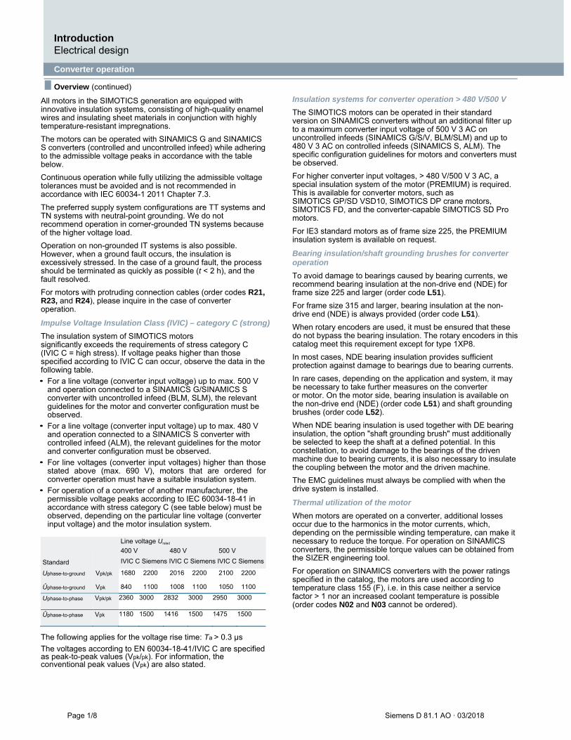
All motors in the SIMOTICS generation are equipped with innovative insulation systems, consisting of high-quality enamel wires and insulating sheet materials in conjunction with highly temperature-resistant impregnations.
The motors can be operated with SINAMICS G and SINAMICS S converters (controlled and uncontrolled infeed) while adhering to the admissible voltage peaks in accordance with the table below.
Continuous operation while fully utilizing the admissible voltage tolerances must be avoided and is not recommended in accordance with IEC 60034-1 2011 Chapter 7.3.
The preferred supply system configurations are TT systems and TN systems with neutral-point grounding. We do not recommend operation in corner-grounded TN systems because of the higher voltage load.
Operation on non-grounded IT systems is also possible. However, when a ground fault occurs, the insulation is excessively stressed. In the case of a ground fault, the process should be terminated as quickly as possible (t < 2 h), and the fault resolved.
For motors with protruding connection cables (order codes R21, R23, and R24), please inquire in the case of converter operation.
Impulse Voltage Insulation Class (IVIC) – category C (strong)
The insulation system of SIMOTICS motors significantly exceeds the requirements of stress category C (IVIC C = high stress). If voltage peaks higher than those specified according to IVIC C can occur, observe the data in the following table.
• For a line voltage (converter input voltage) up to max. 500 V and operation connected to a SINAMICS G/SINAMICS S converter with uncontrolled infeed (BLM, SLM), the relevant guidelines for the motor and converter configuration must be observed.
• For a line voltage (converter input voltage) up to max. 480 V and operation connected to a SINAMICS S converter with controlled infeed (ALM), the relevant guidelines for the motor and converter configuration must be observed.
• For line voltages (converter input voltages) higher than those stated above (max. 690 V), motors that are ordered for converter operation must have a suitable insulation system.
• For operation of a converter of another manufacturer, the permissible voltage peaks according to IEC 60034-18-41 in accordance with stress category C (see table below) must be observed, depending on the particular line voltage (converter input voltage) and the motor insulation system.
Standard
Line voltage Urated
400 V 480 V 500 V
IVIC C Siemens IVIC C Siemens IVIC C Siemens
Uphase-to-ground Vpk/pk 1680 2200 2016 2200 2100 2200
Ûphase-to-ground Vpk 840 1100 1008 1100 1050 1100
Uphase-to-phase Vpk/pk 2360 3000 2832 3000 2950 3000
Ûphase-to-phase Vpk 1180 1500 1416 1500 1475 1500
The following applies for the voltage rise time: Ta > 0.3 µs
The voltages according to EN 60034-18-41/IVIC C are specified as peak-to-peak values (Vpk/pk). For information, the conventional peak values (Vpk) are also stated.
Insulation systems for converter operation > 480 V/500 V
The SIMOTICS motors can be operated in their standard version on SINAMICS converters without an additional filter up to a maximum converter input voltage of 500 V 3 AC on uncontrolled infeeds (SINAMICS G/S/V, BLM/SLM) and up to 480 V 3 AC on controlled infeeds (SINAMICS S, ALM). The specific configuration guidelines for motors and converters must be observed.
For higher converter input voltages, > 480 V/500 V 3 AC, a special insulation system of the motor (PREMIUM) is required. This is available for converter motors, such as SIMOTICS GP/SD VSD10, SIMOTICS DP crane motors, SIMOTICS FD, and the converter-capable SIMOTICS SD Pro motors.
For IE3 standard motors as of frame size 225, the PREMIUM insulation system is available on request.
Bearing insulation/shaft grounding brushes for converter operation
To avoid damage to bearings caused by bearing currents, we recommend bearing insulation at the non-drive end (NDE) for frame size 225 and larger (order code L51).
For frame size 315 and larger, bearing insulation at the non-drive end (NDE) is always provided (order code L51).
When rotary encoders are used, it must be ensured that these do not bypass the bearing insulation. The rotary encoders in this catalog meet this requirement except for type 1XP8.
In most cases, NDE bearing insulation provides sufficient protection against damage to bearings due to bearing currents.
In rare cases, depending on the application and system, it may be necessary to take further measures on the converter or motor. On the motor side, bearing insulation is available on the non-drive end (NDE) (order code L51) and shaft grounding brushes (order code L52).
When NDE bearing insulation is used together with DE bearing insulation, the option "shaft grounding brush" must additionally be selected to keep the shaft at a defined potential. In this constellation, to avoid damage to the bearings of the driven machine due to bearing currents, it is also necessary to insulate the coupling between the motor and the driven machine.
The EMC guidelines must always be complied with when the drive system is installed.
Thermal utilization of the motor
When motors are operated on a converter, additional losses occur due to the harmonics in the motor currents, which, depending on the permissible winding temperature, can make it necessary to reduce the torque. For operation on SINAMICS converters, the permissible torque values can be obtained from the SIZER engineering tool.
For operation on SINAMICS converters with the power ratings specified in the catalog, the motors are used according to temperature class 155 (F), i.e. in this case neither a service factor > 1 nor an increased coolant temperature is possible (order codes N02 and N03 cannot be ordered).
Introduction Electrical design
Siemens D 81.1 AO · 03/2018 Page 1/9
■ Overview (continued)
DURIGNIT IR 2000 insulation
The DURIGNIT IR 2000 insulating system consists of high-quality enamel wires and insulating sheet materials in conjunction with temperature-resistant resin impregnation. This ensures that these motors will have a high mechanical and electrical strength, high service value, and a long service life. The insulating system protects the winding to a large degree against aggressive gases, vapors, dust, oil, and increased air humidity. It can withstand the usual vibration stressing. The insulation is suitable up to an absolute air humidity of 30 g water per m3
of air. Moisture condensation should be prevented from forming on the winding. For higher values, the N30 and N31 options are available – see page 1/10.
Please inquire about extreme applications.
Winding and insulation version with regard to temperature class
At rated power in line operation, the motors can be utilized in the following temperature class: For Simotics SD Add: temperature class 130 (B) For Simotics SD Pro: temperature class 155 (F)
Temperature class 155 (F), utilized acc. to 155 (F), with service factor (SF)
All motors with frame sizes 400 and 450 have a service factor of 1.05 at rated power in line operation. Order code N01
Temperature class 155 (F), utilized acc. to 155 (F), for higher power
When utilized in line operation according to temperature class 155 (F), the rated power specified in the selection and ordering data can be increased by 5 %. In this case, the service factor is 1.0. Order code N02
Temperature class 155 (F), utilized acc. to 155 (F), with increased coolant temperature
In line operation, with power as defined in the catalog, the coolant temperature is permitted to rise to 45 °C. In this case, the service factor is 1.0. Order code N03 In the case of converter-fed operation at the power specified in the catalog, the motors are utilized according to temperature class 155 (F). Order codes N02 and N03 are not possible.
Temperature class 155 (F), utilized acc. to 130 (B), coolant temperature 45 °C, derating approx. 4 %
The Simotics SD Add motor series can be ordered according to temperature class 155 (F) for utilization according to temperature class 130 (B) and a maximum coolant temperature of 45 °C with derating of 4 %. Order code N05
Temperature class 155 (F), utilized acc. to 130 (B), coolant temperature 50 °C, derating approx. 8 %
The Simotics SD Add motor series can be ordered according to temperature class 155 (F) for utilization according to temperature class 130 (B) and a maximum coolant temperature of 50 °C with derating of 8 %. Order code N06
Windings and insulation
1
Temperature class 155 (F), utilized acc. to 130 (B), coolant temperature 55 °C, derating approx. 13 %
The Simotics SD Add motor series can be ordered according to temperature class 155 (F) for utilization according to temperature class 130 (B) and a maximum coolant temperature of 55 °C with derating of 13 %. Order code N07
Temperature class 155 (F), utilized acc. to 130 (B), coolant temperature 60 °C, derating approx. 18 %
The Simotics SD Add motor series can be ordered according to temperature class 155 (F) for utilization according to temperature class 130 (B) and a maximum coolant temperature of 60 °C with derating of 18 %. Order code N08
Temperature class 180 (H)
With the motor, utilization according to temperature class 180 (H) is permitted. The rated power is increased by 5 %. Rating plate data for
direct-on-line (DOL) operation: Prated·1.05 + SF 1.05 operation on converter (VSD): Prated·1.05
Order code N10
Temperature class 180 (H) at rated power and max. CT 60 °C
Utilization according to temperature class 180 (H) at rated power and a maximum coolant temperature of 60 °C is possible on request for the motors. Order code N11.
Temperature class 155 (F) utilized acc. to 130 (B), with higher coolant temperature and/or installation altitude
The motors can be ordered according to temperature class 155 (F) for utilization according to temperature class 130 (B) with other customized requirements if they are specified in plain text in the order. Order code Y50
Temperature class 155 (F), utilized acc. to 155 (F), other requirements
The motors can be ordered according to temperature class 155 (F) for utilization according to temperature class 155 (F) with other customized requirements if they are specified in plain text in the order. Order code Y52
Temperature class 180 (H), utilized acc. to 155 (F)
The motors can be ordered according to temperature class 180 (H) for utilization according to temperature class 155 (F) with other customized requirements if they are specified in plain text in the order. Order code Y75
Introduction Electrical design
Page 1/10 Siemens D 81.1 AO · 03/2018
Windings and insulation
■ Overview (continued)
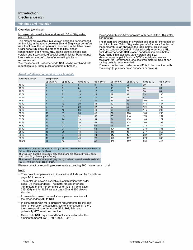
Increased air humidity/temperature with 30 to 60 g water per m3
of air
The motors are available in a version designed for increased air humidity in the range between 30 and 60 g water per m3
air as a function of the temperature, as shown in the table below. Order code N30 (includes order code H03, closed condensation drain holes, M11, rating plate stainless steel version and S02 standard/special paint finish for Performance Line cast-iron motors). Use of non-rusting bolts is recommended. You must contact us if order code N30 is to be combined with mountings (e.g. rotary pulse encoders or brakes).
Increased air humidity/temperature with over 60 to 100 g water per m3
of air
The motors are available in a version designed for increased air humidity of over 60 to 100 g water per m3
of air as a function of the temperature, as shown in the table below. This version contains condensation drain holes (closed), order code N31 (includes order code H03, closed condensation drain holes, M11, rating plate stainless steel version and S02 standard/special paint finish or S03 "special paint sea air resistant" for Performance Line cast-iron motors). Use of non-rusting bolts is recommended. You must contact us if order code N31 is to be combined with mountings (e.g. rotary pulse encoders or brakes).
Absolute/relative conversion of air humidity
100 % 130 197 291 419
Please contact us regarding requirements exceeding 100 g water per m3
of air.
Note:
• The coolant temperature and installation altitude can be found from page 1/11 onwards.
• The metal fan cover is available in combination with order code F74 (not standard). The metal fan cover for cast-iron motors of the Performance Line (1LE16 frame sizes 315-355) and for 1LE5 frame sizes 400 and 450 always standard.
• In case of increased thermal stress, please combine with the order codes N05 to N08.
• In conjunction with more stringent requirements for the paint finish or corrosion protection stress (offshore, sea air, etc.), the corresponding order codes S02, S03, S04, and potentially H07, must be combined.
• Order code N31 requires additional specifications for the ambient temperature CT 50 °C to CT 90 °C.
The values in the table with a blue background are covered by the standard version (up to < 30 g water per m3
of air). The values in the table with a light gray background are covered by order code N30 (30 to 60 g of water per m3
of air). The values in the table with a dark gray background are covered by order code N31 (60 to < 100 g of water per m3
of air).
Relative humidity Temperature
up to 20 °C up to 30 °C up to 40 °C up to 50 °C up to 60 °C up to 70 °C up to 80 °C up to 90 °C
10 % 2 3 5 8 13 20 29 42
15 % 3 5 8 12 19 30 44 63
20 % 3 6 10 17 26 39 58 84
25 % 4 8 13 21 32 49 73 105
30 % 5 9 15 25 39 59 87 126
35 % 6 11 18 29 45 69 102 146
40 % 7 12 20 33 52 79 116 167
45 % 8 14 23 37 58 89 131 188
50 % 9 15 26 41 65 98 145 209
55 % 10 17 28 46 71 108 160 230
60 % 10 19 31 50 78 118 174 251
65 % 11 20 33 54 84 128 189 272
70 % 12 21 36 58 91 138 203 293
75 % 13 23 38 62 97 148 218 314
80 % 14 24 41 66 104 157 233 335
85 % 15 26 43 70 110 167 247 356
90 % 16 27 46 74 117 177 262 377
95 % 16 29 49 79 123 187 276 398
17 30 51 83
Introduction Electrical design
Siemens D 81.1 AO · 03/2018 Page 1/11
■ Overview (continued)
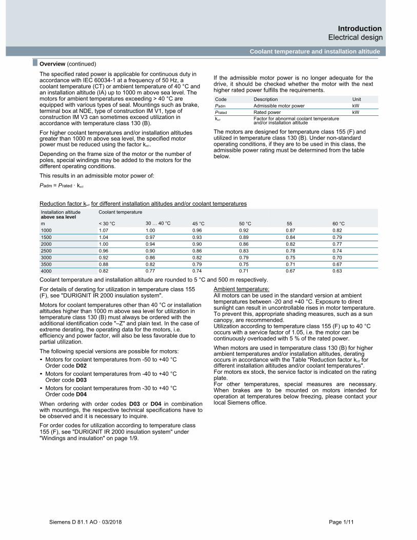
The specified rated power is applicable for continuous duty in accordance with IEC 60034-1 at a frequency of 50 Hz, a coolant temperature (CT) or ambient temperature of 40 °C and an installation altitude (IA) up to 1000 m above sea level. The motors for ambient temperatures exceeding > 40 °C are equipped with various types of seal. Mountings such as brake, terminal box at NDE, type of construction IM V1, type of construction IM V3 can sometimes exceed utilization in accordance with temperature class 130 (B).
For higher coolant temperatures and/or installation altitudes greater than 1000 m above sea level, the specified motor power must be reduced using the factor kHT.
Depending on the frame size of the motor or the number of poles, special windings may be added to the motors for the different operating conditions.
This results in an admissible motor power of:
Padm = Prated · kHT
Coolant temperature and installation altitude
1 If the admissible motor power is no longer adequate for the drive, it should be checked whether the motor with the next higher rated power fulfills the requirements.
Padm Admissible motor power kW
Prated Rated power kW
kHT Factor for abnormal coolant temperature and/or installation altitude
The motors are designed for temperature class 155 (F) and utilized in temperature class 130 (B). Under non-standard operating conditions, if they are to be used in this class, the admissible power rating must be determined from the table below.
Reduction factor kHT for different installation altitudes and/or coolant temperatures
0.82 0.77 0.74 0.71 0.67 0.63
Coolant temperature and installation altitude are rounded to 5 °C and 500 m respectively.
For details of derating for utilization in temperature class 155 (F), see "DURIGNIT IR 2000 insulation system".
Motors for coolant temperatures other than 40 °C or installation altitudes higher than 1000 m above sea level for utilization in temperature class 130 (B) must always be ordered with the additional identification code "–Z" and plain text. In the case of extreme derating, the operating data for the motors, i.e. efficiency and power factor, will also be less favorable due to partial utilization.
The following special versions are possible for motors:
• Motors for coolant temperatures from -50 to +40 °C Order code D02
• Motors for coolant temperatures from -40 to +40 °C Order code D03
• Motors for coolant temperatures from -30 to +40 °C Order code D04
When ordering with order codes D03 or D04 in combination with mountings, the respective technical specifications have to be observed and it is necessary to inquire.
For order codes for utilization according to temperature class 155 (F), see "DURIGNIT IR 2000 insulation system" under "Windings and insulation" on page 1/9.
Ambient temperature: All motors can be used in the standard version at ambient temperatures between -20 and +40 °C. Exposure to direct sunlight can result in uncontrollable rises in motor temperature. To prevent this, appropriate shading measures, such as a sun canopy, are recommended. Utilization according to temperature class 155 (F) up to 40 °C occurs with a service factor of 1.05, i.e. the motor can be continuously overloaded with 5 % of the rated power.
When motors are used in temperature class 130 (B) for higher ambient temperatures and/or installation altitudes, derating occurs in accordance with the Table "Reduction factor kHT for different installation altitudes and/or coolant temperatures". For motors ex stock, the service factor is indicated on the rating plate. For other temperatures, special measures are necessary. When brakes are to be mounted on motors intended for operation at temperatures below freezing, please contact your local Siemens office.
Code Description Unit
Installation altitude above sea level m
< 30 °C
30 … 40 °C
45 °C
50 °C
55 �
60 °C
1000 1.07 1.00 0.96 0.92 0.87 0.82
1500 1.04 0.97 0.93 0.89 0.84 0.79
2000 1.00 0.94 0.90 0.86 0.82 0.77
2500 0.96 0.90 0.86 0.83 0.78 0.74
3000 0.92 0.86 0.82 0.79 0.75 0.70
3500 0.88 0.82 0.79 0.75 0.71 0.67
4000
Coolant temperature
Introduction Electrical design
Page 1/12 Siemens D 81.1 AO · 03/2018
Heating and ventilation
■ Overview (continued)
Anti-condensation heater
Supply voltage 230 V (1 AC) Order code Q02
Supply voltage 115 V (1 AC) Order code Q03
Supply voltage 400 V (1 AC) Order code Q06
For motors with windings at risk of condensation due to the climatic conditions, e.g. inactive motors in humid atmospheres or motors that are subjected to widely fluctuating temperatures, anti-condensation heaters must be used. An additional cable entry is provided for the connecting cable in the terminal box. Motor series Frame size Cable entry
Cast-iron motors (SD) 400 ... 450 2 M20 1.5
Anti-condensation heating must not be switched on during operation.
Frame size Heat output of the anti-condensation heating Supply voltage at 230 V 115 V (110 V) 400 V Order code Q02 Order code Q03 Order code Q06 W W W Motors 1LE5 400 … 450 240 240 370
Instead of an anti-condensation heater, another possibility is the connection of a voltage that is approximately 4 to 10 % of the rated motor voltage to stator terminals U1 and V1. 20 to 30 % of the motor rated current is normally sufficient to provide adequate heating.
Fans/separately driven fans All motors with 4 or more poles have radial-flow fans in the standard version (with the exception of option F90 – version "Forced-air cooled motors without external fan and fan cover") that cool regardless of the direction of rotation of the
motor (cooling method IC411 acc. to EN 60034-6). 1LE5 motors with 2 poles are cooled with axial fans specific to the direction of rotation. The air flow is forced from the non-drive-end (NDE) to the drive end (DE) in all motors.
Supply voltage of separately driven fan for motors: The supply voltage tolerance of the separately driven fan is ±5 %. In confined spaces, it must be ensured that the minimum spacing is maintained between the fan cover and the wall. This also applies to adjacent parts, such as large handwheels and flywheels on the second shaft extension.
For version of the fan and the fan cover, see the table below.
Metal external fan impeller The standard fan impeller made of plastic can be replaced with a fan impeller made of metal. This version is available for the motors (with the exception of 1LE1 with option F90 – version "Forced-air cooled motors without external fan and fan cover"). A metal external fan is already included for the low-noise version. For 2-pole versions with frame sizes 400 and 450, the metal external fan impeller is made of aluminum. Order code F76
Sheet metal fan cover For motor series 1LE5 (with the exception of 1LE5 with option F90 – version "Forced-air cooled motors without external fan and fan cover"), the sheet metal fan cover is provided as standard.
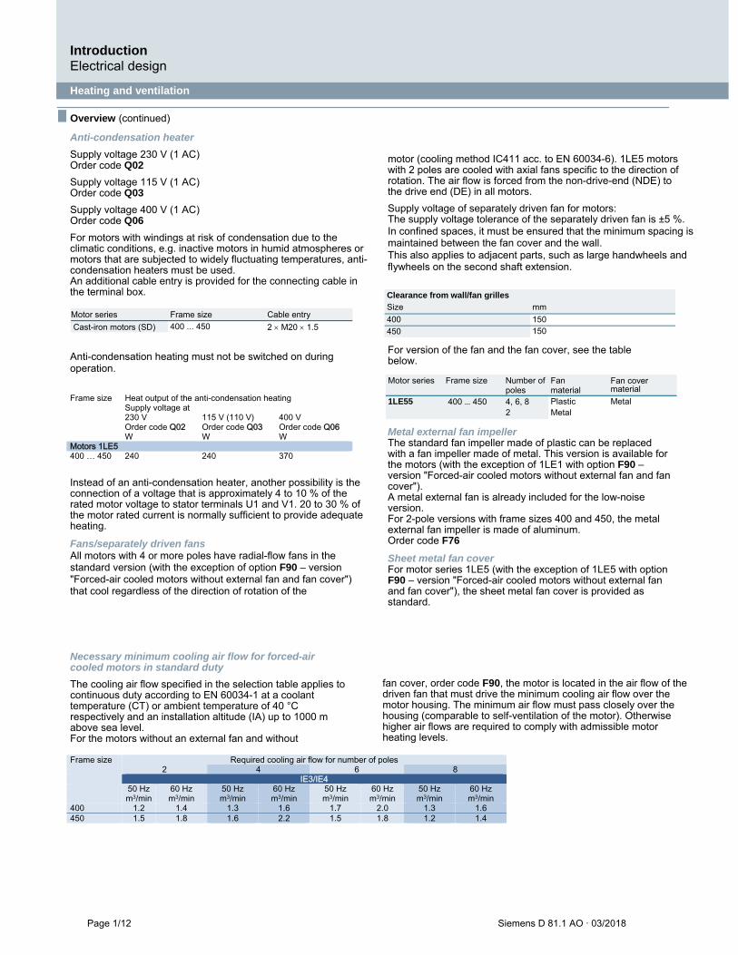
Necessary minimum cooling air flow for forced-air cooled motors in standard duty
The cooling air flow specified in the selection table applies to continuous duty according to EN 60034-1 at a coolant temperature (CT) or ambient temperature of 40 °C respectively and an installation altitude (IA) up to 1000 m above sea level. For the motors without an external fan and without
fan cover, order code F90, the motor is located in the air flow of the driven fan that must drive the minimum cooling air flow over the motor housing. The minimum air flow must pass closely over the housing (comparable to self-ventilation of the motor). Otherwise higher air flows are required to comply with admissible motor heating levels.
Frame size Required cooling air flow for number of poles 2 4 6 8 IE3/IE4 50 Hz
m3/min 60 Hz m3/min
50 Hz m3/min
60 Hz m3/min
50 Hz m3/min
60 Hz m3/min
50 Hz m3/min
60 Hz m3/min
400 1.2 1.4 1.3 1.6 1.7 2.0 1.3 1.6 450 1.5 1.8 1.6 2.2 1.5 1.8 1.2 1.4
Clearance from wall/fan grilles
Size mm
400 150
450 150
Motor series Frame size Number of poles
Fan material
Fan cover material
1LE55 400 … 450 4, 6, 8 Plastic Metal 2 Metal
Introduction Electrical design
Connection, circuit and terminal boxes
Siemens D 81.1 AO · 03/2018 Page 1/13
■ Overview (continued)
Terminal box position
The terminal box of the motor can be mounted in four different locations or positions (see from page 2/5). The position of the terminal box is coded using the 16th position of the motor Article No. When defining the position of the terminal box, please observe the following:
• Motors with feet must always be viewed looking onto the drive end with the shaft in the horizontal position. The feet are then always at "6 o'clock". This is especially important with construction types IM B6, IM B7, and IM B8, and also applies to combined construction types such as IM B35.
• Flange-mounting motors (e.g. IM B5) whose drive-end flange has a condensation drainage hole must always be viewed looking onto the drive end with the shaft in the horizontal position. The condensation drainage hole is then always at "6 o'clock".
The number of winding ends depends on the winding design. Three-phase motors are connected to the three phase conductors L1, L2 and L3 of a three-phase system. The rated voltage of the motor in the running connection must match the phase conductor voltages of the network.
When the three phases are operating in a time sequence and are connected to the terminals of the motor in alphabetical order U1, V1 and W1, clockwise rotation of the motor shaft is established as viewed onto the drive end. The direction of rotation of the motor can be changed to counterclockwise if two connecting leads are interchanged.
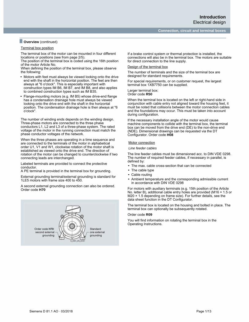
Labeled terminals are provided to connect the protective conductor. A PE terminal is provided in the terminal box for grounding.
External grounding terminal/external grounding is standard for 1LE5 motors with frame size 400 to 450.
A second external grounding connection can also be ordered. Order code H70
If a brake control system or thermal protection is installed, the connections will also be in the terminal box. The motors are suitable for direct connection to the line supply.
Design of the terminal box
The number of terminals and the size of the terminal box are designed for standard requirements.
For special requirements, or on customer request, the largest terminal box 1XB7750 can be supplied.
Larger terminal box: Order code R50
When the terminal box is located on the left or right-hand side in conjunction with cable entry not aligned toward the housing feet, it must be noted that collisions between the motor connection cables and the foundations may occur. This must be taken into account during configuration.
If the necessary installation angle of the motor would cause machine components to collide with the terminal box, the terminal box can be moved from the drive end (DE) to the non-drive end (NDE). Dimensional drawings can be requested via the DT Configurator. Order code H08 Motor connection
Line feeder cables
The line feeder cables must be dimensioned acc. to DIN VDE 0298. The number of required feeder cables, if necessary in parallel, is defined by: • The max. cable cross-section that can be connected • The cable type • Cable routing • Ambient temperature and the corresponding admissible current
in accordance with DIN VDE 0298
For motors with auxiliary terminals (e.g. 15th position of the Article No. letter B), additional cable entry holes are provided (M16 × 1.5 or M20 × 1.5 depending on frame size). For further details, see the data sheet function in the DT Configurator.
The terminal box is located on the housing and bolted in place. The terminal box can optionally be subsequently rotated.
Order code R09
You will find information on rotating the terminal box in the Operating Instructions.

Introduction Electrical design
Connection, circuit and terminal boxes
Page 1/14 Siemens D 81.1 AO · 03/2018
■ Overview (continued)
Parallel feeders Some motors must be fitted with parallel feeders due to the maximum permissible current per terminal. These motors are indicated in the selection and ordering data in the respective chapter. The temperature rises in the terminal box must be taken into account when selecting the connection cable or individual connections. These approximate temperature rises are as follows: • Range of ambient temperature (Tamb) +50 K for motors
with temperature class Th.Cl.155 (F). • Range of ambient temperature (Tamb) +60 K for motors
with temperature class Th.Cl.180 (F). • Without any specifications in field 19 (Tamb) on the rating
plate, Tamb is equal to 40 °C.
The terminal box can be rotated on the base of the motor housing such that the cable entry is located in the positions given below: • Toward the drive end (DE) (rotation of terminal box through 90°,
entry from DE) for flange motors (IM B5, IM B35, and IM V1) only possible with order code H08!
• Toward the fan end (NDE) (rotation of terminal box through 90°, entry from NDE) Order code R11
• Opposite the standard position 0° (rotation of terminal box by 180°, entry opposite the standard position 0°) Order code R12
The dimensions of the terminal box are listed in the section "Dimensions" on pages 2/32 and 2/33 in accordance with the frame size and the "Dimensional drawings". If the position of the terminal box (right-hand side, left-hand side, or top) is changed, the position of the cable entry must be checked and, if necessary, ordered with the corresponding order codes (R10, R11, and R12). Restrictions may result depending on the terminal box type, type of construction, terminal box position, and direction of cable entry. You will find more information on page 1/17.
Location of the cable entries with the corresponding order codes Motor Frame size Terminal box Terminal box position
top top 45° 45° 90° 90° bottom -90° +90° 180° can be left right left right right left converted
subsequently 16th position of Article No. and Article No. with -Z with specification of order code, Article No. with -Z Order code
Type Type 0 1 2 3 5 6 9 R10 2) R11 R12
1LE5 400 TB3R61 ✔ ✔ ✔ ✔ ✔ ✔ ✔ ✔ ✔ ✔ no1) 450 TB3R61 ✔ ✔ ✔ ✔ ✔ ✔ ✔ ✔ ✔ ✔ no1)
1) Only possible with order code R09 2) Only possible for flange with order code H08
Introduction Electrical design
Connection, circuit and terminal boxes
Siemens D 81.1 AO · 03/2018 Page 1/15
■ Overview (continued)
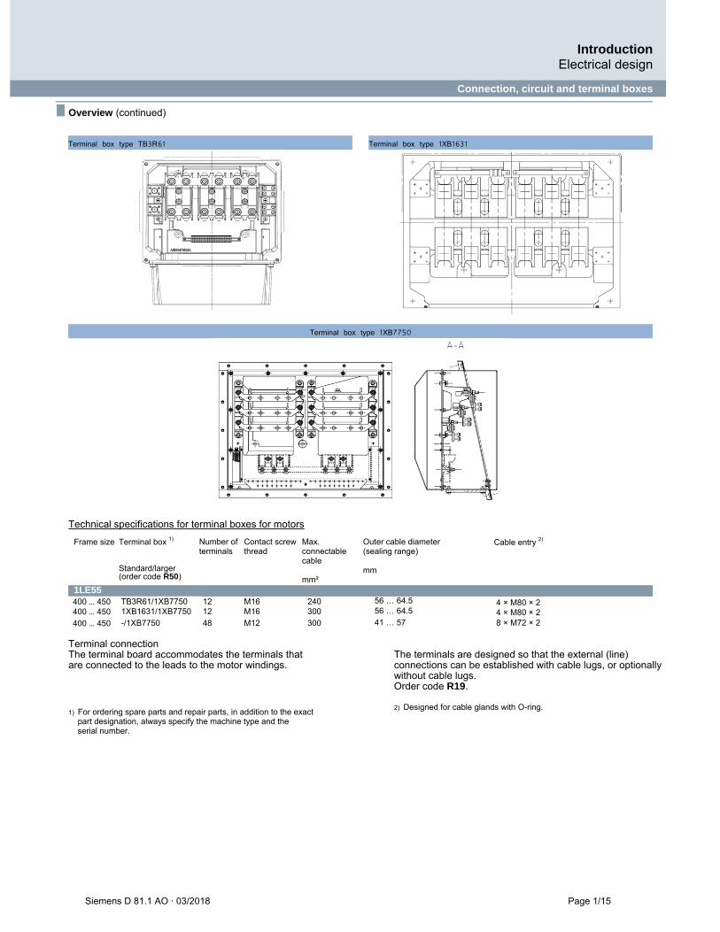
Terminal box type TB3R61 Terminal box type 1XB1631
Terminal box type 1XB7750
Technical specifications for terminal boxes for motors
Frame size Terminal box 1)
Standard/larger (order code R50)
Number of terminals
Contact screw thread
Max. connectable cable mm²
Outer cable diameter (sealing range) mm
Cable entry 2)
1LE55 400 … 450 TB3R61/1XB7750 12 M16 240 56 … 64.5 4 × M80 × 2 400 … 450 1XB1631/1XB7750 12 M16 300 56 … 64.5 4 × M80 × 2 400 … 450 -/1XB7750 48 M12 300 41 … 57 8 × M72 × 2
Terminal connection The terminal board accommodates the terminals that are connected to the leads to the motor windings.
The terminals are designed so that the external (line) connections can be established with cable lugs, or optionally without cable lugs. Order code R19.
1) For ordering spare parts and repair parts, in addition to the exact part designation, always specify the machine type and the serial number.
2) Designed for cable glands with O-ring.
Introduction Mechanical design
Page 1/16 Siemens D 81.1 AO · 03/2018
■ Overview (continued)
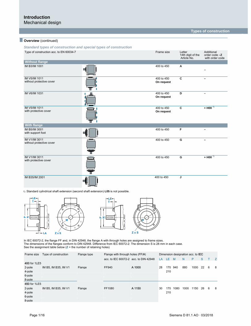
Standard types of construction and special types of construction
Types of construction
1
1) Standard cylindrical shaft extension (second shaft extension) L05 is not possible.
In IEC 60072-2, the flange FF and, in DIN 42948, the flange A with through holes are assigned to frame sizes. The dimensions of the flanges conform to DIN 42948. Difference from IEC 60072-2: The dimension S is 28 mm in each case. See the assignment table below (Z = the number of retaining holes)
Type of construction acc. to EN 60034-7 Frame size Letter Additional 14th digit of the order code –Z Article No. with order code
Without flange IM B3/IM 1001 400 to 450 A
–
IM V5/IM 1011 without protective cover
400 to 450 C – On request
IM V6/IM 1031 400 to 450 D – On request
IM V5/IM 1011 with protective cover
400 to 450 C + H00 1)
On request
With flange IM B5/IM 3001 with support foot
400 to 450 F –
IM V1/IM 3011 without protective cover
400 to 450 G –
IM V1/IM 3011 with protective cover
400 to 450 G + H00 1)
IM B35/IM 2001 400 to 450 J
Frame size Type of construction Flange type Flange with through holes (FF/A) Dimension designation acc. to IEC acc. to IEC 60072-2 acc. to DIN 42948 LA LE M N P S T Z 400 for 1LE5 2-pole IM B5, IM B35, IM V1 Flange FF940 A 1000 28 170 940 880 1000 22 6 8 4-pole 210 6-pole 8-pole 450 for 1LE5 2-pole IM B5, IM B35, IM V1 Flange FF1080 A 1150 30 170 1080 1000 1150 26 6 8 4-pole 210 6-pole 8-pole
Introduction Mechanical design
Bearings and lubrication
Siemens D 81.1 AO · 03/2018 Page 1/17
■ Overview (continued)
Bearing lifetime (nominal lifetime)
The nominal bearing lifetime is defined according to standardized calculation procedures (ISO 281) and is reached or even exceeded for 90 % of the bearings when the motors are operated in compliance with the data provided in the catalog.
Generally, the bearing lifetime is defined by the bearing size, the bearing load, the operating conditions, the speed and the grease lifetime. A bearing lifetime calculation is possible on request.
Bearing system
The bearing lifetime of motors with horizontal mounting is 40,000 hours if there is no additional axial loading at the coupling output and 20,000 hours when utilized according to the maximum admissible load. This assumes that the motor is operated at 50 Hz. The nominal bearing lifetime is reduced for converter operation at higher frequencies.
To achieve the calculated lifetime in continuous duty, for the admissible vibration values measured at the bearing plate, evaluation zones A and B specified in ISO 10816 are applicable. If higher vibration speeds will occur under the operating conditions, special measures will be necessary (please inquire).
Due to their physical characteristics, variable-speed motors have a different bearing lifetime under the same load conditions. This relationship is linear, i.e. if the frequency increases by 20 % from 50 Hz to 60 Hz, the lifetime decreases by 20 % from 20,000 to 16,000 hours under the load conditions specified in the catalog. If the frequency falls by 20 % from 50 Hz to 40 Hz, the lifetime rises by 20 % from 20,000 to 24,000 hours under the load conditions specified in the catalog.
It should be observed that, for types of construction IM V5 and IM V6, the belt tension is only permitted to be exerted parallel to the mounting plane or toward the mounting plane and the feet must be supported. Both feet must be secured for foot-mounting types of construction.
In the basic bearing system, the located bearing is situated at the drive end (DE) and the floating bearing is situated at the non-drive end (NDE).
The bearing system is axially preloaded with a spring element at the non-drive end (NDE) to ensure smooth running of the motor without play (see Fig. 1 in the diagrams of bearings on page 1/19).
If required, the located bearing can be fitted at the non-drive end (NDE). Order code L21
For increased cantilever forces (e.g. belt drives), reinforced bearings can be used at the drive end (DE). The versions with cylindrical roller bearings are not axially preloaded and must always run under adequate radial loads (motors must not be operated on a test bed without additional radial loads). The located bearing is positioned at the non-drive end (NDE). Order code L22
The 1LE5 motors can be supplied with reinforced bearings (size range 03) at both ends. In this case, the bearing plates are made of cast iron. Order code L25
A measuring nipple for SPM shock pulse measurement can be mounted to check bearing vibration. The motors have an M8 tapped hole for each bearing plate and a measuring nipple with a protective cap. If a second tapped hole is provided, it is fitted with a sealing cap.
Order code Q01
Bearing insulation
To prevent damage caused by bearing currents, insulated bearings are absolutely necessary for frame sizes 400 to 450 in converter operation. • L50 (bearing insulation DE) • L51 (bearing insulation NDE) • L50 + L51 (DE and NDE bearings insulated) • Combination of order codes L50 or L51 or L50 + L51 with L22
(bearing version for increased cantilever forces)
It is up to the user in the case of DE bearing insulation (order code L50) + NDE bearing insulation (order code L51) to ensure grounding of the rotor.
The rotor grounding can be implemented either in the system via the coupled driven machine or in the motor via a grounding brush.
The grounding brush (order code L52) must always be provided when the driven machine is connected to the motor via an insulating coupling or an insulating belt output shaft.
Relubrication
For motors that can be regreased at defined regreasing intervals, the bearing lifetime can be extended and/or unfavorable factors such as temperature, mounting conditions, speed, bearing size, and mechanical load can be compensated.
For frame sizes 400 to 450, a regreasing device with a flat lubricating nipple DIN3404-AM10x1-5.8-A is standard.
For frame sizes 400 to 450, a regreasing device with a tapered lubricating nipple DIN71412-AM10x1-5.8 can be ordered. Order code L19
In the case of motors equipped with regreasing device, information regarding regreasing intervals, quantity of grease, type of grease and any additional data is provided on the lubrication plate or rating plate. For regreasing intervals for the basic version, see the Table "Grease lifetime and regreasing intervals for horizontal installation".
Mechanical stress and grease service life
High speeds that exceed the rated speed with converter operation and the resulting increased vibrations alter the mechanical smooth running operation and the bearings are subject to increased mechanical stress. This reduces the grease lifetime and the bearing lifetime (please inquire where applicable).
The use of rigid couplings should be avoided as far as possible. For converter operation in particular, compliance with the mechanical limit speeds nmax at maximum supply frequency fmax is essential, see the following table "Mechanical limit speeds nmax at maximum supply frequency fmax".

Introduction Mechanical design
Bearings and lubrication
Page 1/18 Siemens D 81.1 AO · 03/2018
■ Overview (continued)
Mechanical limit speeds nmax at maximum supply frequency fmax (standard values) for motors – basic version
The specified limit speeds are applicable to motors without additional mountings, such as brakes or rotary encoders. In such applications, the characteristics of the respective mounting parts must be taken into account.
Grease lifetime and regreasing intervals for horizontal installation
Bearing selection table for motors – basic version
The bearing selection tables are only intended for planning purposes. Authoritative information on the actual type of bearings fitted in motors already supplied can be obtained from the factory by quoting the serial number or can be read from the rating plate.
Bearing selection table for motors (basic version)
Bearing selection table for motors (bearings reinforced at both ends – order code L25)
1) If the coolant temperature is increased by 10 K, the grease lifetime and regreasing interval are halved.
2) Version only possible with steel bearing plates. Order on request with additional charge.
Motor series Frame size No. of poles Regreasing 1)
CT≤40 °C
1LE5 400 2 4 ... 8
4000 h 6000 h
450 2 3000 h 4 ... 8 6000 h
Frame size Type 2-pole 4-pole 6-pole 8-pole
nmax fmax nmax fmax nmax fmax nmax fmax
rpm Hz rpm Hz rpm Hz rpm Hz 1LE5 – basic version
1LE55..-
400 4A… IM B3 3600 60 2200 74 2200 110 2200 147
450 4B… IM B3 3600 2) 50 2100 70 2100 105 2100 140
400 4A… IM V1 3100 52 2100 70 2100 105 2100 140
450 4B… IM V1 - - 1800 60 1800 90 1800 120
Frame size No. of poles Drive end DE bearing Non-drive end NDE bearing Fig. no. on page 1/19 Horizontal and vertical type of constr. Horizontal and vertical type of constr.
1LE5 400 2 6218 C3 7218 B + 6218 C3 6218 C3 6218 C3 Fig. 6 and Fig. 7
4, 6, 8 6224 C3 7224 B + 6224 C3 6224 C3 6224 C3 Fig. 6 and Fig. 7 450 2 6220 C3 - 6220 C3 - Fig. 6
4, 6, 8 6226 C3 7226 B + 6226 C3 6226 C3 6226 C3 Fig. 6 and Fig. 7
Frame size No. of poles Drive end DE bearing Non-drive end NDE bearing Fig. no. on page 1/19
Horizontal and vertical type of constr. Horizontal and vertical type of constr.
1LE5
400 2 O.R. O.R. O.R. O.R. Fig. 6 and Fig. 7
4, 6, 8 6326 C3 O.R. 6326 C3 O.R. Fig. 6 and Fig. 7
450 2 O.R. - O.R. - Fig. 6
4, 6, 8 6326 C3 O.R. 6326 C3 O.R. Fig. 6 and Fig. 7
Introduction Mechanical design
Bearings and lubrication
Siemens D 81.1 AO · 03/2018 Page 1/19
■ Overview (continued)
Diagrams of bearings
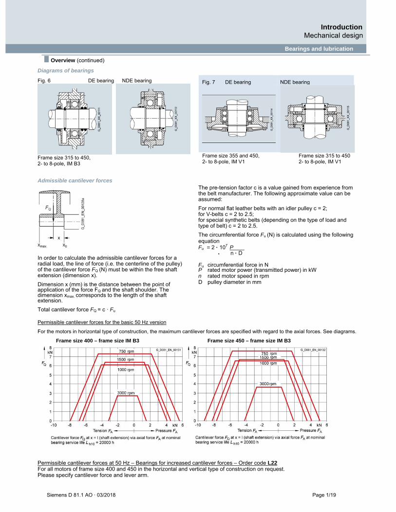
Fig. 6 DE bearing NDE bearing
Frame size 315 to 450, 2- to 8-pole, IM B3
Frame size 355 and 450, Frame size 315 to 450 2- to 8-pole, IM V1 2- to 8-pole, IM V1
Admissible cantilever forces
In order to calculate the admissible cantilever forces for a radial load, the line of force (i.e. the centerline of the pulley) of the cantilever force FQ (N) must be within the free shaft extension (dimension x).
Dimension x (mm) is the distance between the point of application of the force FQ and the shaft shoulder. The dimension xmax. corresponds to the length of the shaft extension.
Total cantilever force FQ = c · Fu
1 The pre-tension factor c is a value gained from experience from the belt manufacturer. The following approximate value can be assumed:
For normal flat leather belts with an idler pulley c = 2; for V-belts c = 2 to 2.5; for special synthetic belts (depending on the type of load and type of belt) c = 2 to 2.5.
The circumferential force Fu (N) is calculated using the following equation Fu = 2 · 107
P
n · D Fu circumferential force in N P rated motor power (transmitted power) in kW n rated motor speed in rpm
D pulley diameter in mm
Permissible cantilever forces for the basic 50 Hz version
For the motors in horizontal type of construction, the maximum cantilever forces are specified with regard to the axial forces. See diagrams.
Frame size 400 – frame size IM B3 Frame size 450 – frame size IM B3
Permissible cantilever forces at 50 Hz – Bearings for increased cantilever forces – Order code L22 For all motors of frame size 400 and 450 in the horizontal and vertical type of construction on request. Please specify cantilever force and lever arm.
Fig. 7 DE bearing NDE bearing
Introduction Mechanical design
Bearings and lubrication
Page 1/20 Siemens D 81.1 AO · 03/2018
■ Overview (continued)
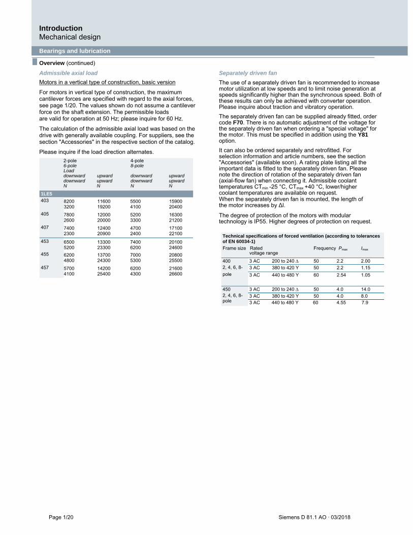
Admissible axial load
Motors in a vertical type of construction, basic version
For motors in vertical type of construction, the maximum cantilever forces are specified with regard to the axial forces, see page 1/20. The values shown do not assume a cantilever force on the shaft extension. The permissible loads are valid for operation at 50 Hz; please inquire for 60 Hz.
The calculation of the admissible axial load was based on the drive with generally available coupling. For suppliers, see the section "Accessories" in the respective section of the catalog.
Please inquire if the load direction alternates.
2-pole 4-pole 6-pole 8-pole Load downward upward downward upward downward upward downward upward N N N N
1LE5
403 8200 11600 5500 15900 3200 19200 4100 20400
405 7800 12000 5200 16300 2600 20000 3300 21200
407 7400 12400 4700 17100 2300 20900 2400 22100
453 6500 13300 7400 20100 5200 23300 6200 24600
455 6200 13700 7000 20800 4800 24300 5300 25500
457 5700 14200 6200 21600 4100 25400 4300 26600
Separately driven fan
The use of a separately driven fan is recommended to increase motor utilization at low speeds and to limit noise generation at speeds significantly higher than the synchronous speed. Both of these results can only be achieved with converter operation. Please inquire about traction and vibratory operation.
The separately driven fan can be supplied already fitted, order code F70. There is no automatic adjustment of the voltage for the separately driven fan when ordering a "special voltage" for the motor. This must be specified in addition using the Y81 option.
It can also be ordered separately and retrofitted. For selection information and article numbers, see the section "Accessories" (available soon). A rating plate listing all the important data is fitted to the separately driven fan. Please note the direction of rotation of the separately driven fan (axial-flow fan) when connecting it. Admissible coolant temperatures CTmin -25 °C, CTmax +40 °C, lower/higher coolant temperatures are available on request. When the separately driven fan is mounted, the length of the motor increases by ∆l.
The degree of protection of the motors with modular technology is IP55. Higher degrees of protection on request.
Technical specifications of forced ventilation (according to tolerances of EN 60034-1)
Frame size Rated Frequency Pmax Imax voltage range
400 3 AC 200 to 240 50 2.2 2.00 2, 4, 6, 8- 3 AC 380 to 420 Y 50 2.2 1.15 pole 3 AC 440 to 480 Y 60 2.54 1.05
450 2, 4, 6, 8-pole
3 AC 200 to 240 50 4.0 14.0
3 AC 380 to 420 Y 50 4.0 8.0 3 AC 440 to 480 Y 60 4.55 7.9
SIMOTICS SD standard motors next generation 2
2/2
2/2 2/4 2/7 2/8
Orientation
Overview, benefits, application, configuration, technical specifications, more information Article No. code
2/9
2/9
Motors with IE4 Super Premium Efficiency
Self-ventilated or forced-air cooled motors SIMOTICS SD Add cast-iron series • 1LE5534
2/11
2/11
2/13
Motors with IE3 Premium Efficiency
Self-ventilated or forced-air cooled motors SIMOTICS SD Add cast-iron series • 1LE5533
SIMOTICS SD Pro cast-iron series • 1LE5583
2/15
2/15 2/16 2/18 2/19 2/20
Article No. supplements and special versions
Voltages Types of construction Motor protection Terminal box position Options
2/32
2/32
2/32
Dimensions
SIMOTICS SD Add self-ventilated motors – cast-iron series • 1LE5534 • 1LE5533
SIMOTICS SD Pro self-ventilated motors – cast-iron series • 1LE5583
SIMOTICS SD standard motors next generation Orientation
Page 2/2 Siemens D 81.1 AO · 03/2018
Overview
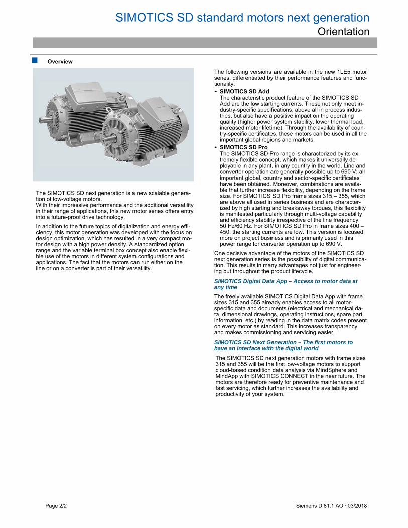
The SIMOTICS SD next generation is a new scalable genera-tion of low-voltage motors. With their impressive performance and the additional versatility in their range of applications, this new motor series offers entry into a future-proof drive technology.
In addition to the future topics of digitalization and energy effi-ciency, this motor generation was developed with the focus on design optimization, which has resulted in a very compact mo-tor design with a high power density. A standardized option range and the variable terminal box concept also enable flexi-ble use of the motors in different system configurations and applications. The fact that the motors can run either on the line or on a converter is part of their versatility.
The following versions are available in the new 1LE5 motor series, differentiated by their performance features and func-tionality: • SIMOTICS SD Add
The characteristic product feature of the SIMOTICS SD Add are the low starting currents. These not only meet in-dustry-specific specifications, above all in process indus-tries, but also have a positive impact on the operating quality (higher power system stability, lower thermal load, increased motor lifetime). Through the availability of coun-try-specific certificates, these motors can be used in all the important global regions and markets.
• SIMOTICS SD Pro The SIMOTICS SD Pro range is characterized by its ex-tremely flexible concept, which makes it universally de-ployable in any plant, in any country in the world. Line and converter operation are generally possible up to 690 V; all important global, country and sector-specific certificates have been obtained. Moreover, combinations are availa-ble that further increase flexibility, depending on the frame size. For SIMOTICS SD Pro frame sizes 315 – 355, which are above all used in series business and are character-ized by high starting and breakaway torques, this flexibility is manifested particularly through multi-voltage capability and efficiency stability irrespective of the line frequency 50 Hz/60 Hz. For SIMOTICS SD Pro in frame sizes 400 – 450, the starting currents are low. This version is focused more on project business and is primarily used in this power range for converter operation up to 690 V.
One decisive advantage of the motors of the SIMOTICS SD next generation series is the possibility of digital communica-tion. This results in many advantages not just for engineer-ing but throughout the product lifecycle.
SIMOTICS Digital Data App – Access to motor data at any time
The freely available SIMOTICS Digital Data App with frame sizes 315 and 355 already enables access to all motor-specific data and documents (electrical and mechanical da-ta, dimensional drawings, operating instructions, spare part information, etc.) by reading in the data matrix codes present on every motor as standard. This increases transparency and makes commissioning and servicing easier.
SIMOTICS SD Next Generation – The first motors to have an interface with the digital world
The SIMOTICS SD next generation motors with frame sizes 315 and 355 will be the first low-voltage motors to support cloud-based condition data analysis via MindSphere and MindApp with SIMOTICS CONNECT in the near future. The motors are therefore ready for preventive maintenance and fast servicing, which further increases the availability and productivity of your system.

SIMOTICS SD standard motors next generation Orientation
Siemens D 81.1 AO · 03/2018 Page 2/3
Benefits
• Rugged design in cast-iron housing increases reliability and availability.
• Compact dimensions/high power density enable use even in confined space conditions.
• High energy efficiency on the line (IE3, IE4) and on a con-verter (IES2) enable energy-saving operation.
• A standardized range of options and a variable terminal box concept increase flexible adaptation to the re-quirements of the application.
• Support of line and converter operation reduces variety.
• Provision of comprehensive CAD data simplifies the design and engineering phase.
Application
SIMOTICS SD next generation motors are ideal for use in a large number of standard applications, such as • Pumps, fans, compressors
• Conveyors
• Winders
• Mixers
• Extruders
• Cranes
They are preferably used in industries such as • Mining, cement
• Chemical
• Oil and gas
• Steel
• Water, waste water
• Heating, ventilation, and air-conditioning (HVAC)
• Pulp and paper
• Marine engineering
3
SIMOTICS SD standard motors next generation Orientation
Page 2/4 Siemens D 81.1 AO · 03/2018
Technical specifications
Converter operation The motors are suitable for line operation and optionally for converter operation (bearing insulation NDE, order code L51). The values specified in the selection tables apply to sinusoidal feeding.
Rated voltage
For the rated voltage, the tolerance according to EN 60034-1 always applies. A rated voltage range is not specified.
Motor protection
A motor protection function can be implemented using the I2t sensing circuit implemented in the converter software.
If required, more precise motor protection can be provided by direct temperature measurement using KTY84 sensors, Pt100/Pt1000 resistance thermometers or PTC thermistors in the motor winding. Some converters from Siemens determine the motor temperature using the resistance of the temperature sen-sor. They can be set to a required temperature for alarming and tripping.
Bearings
To avoid damage caused by bearing currents, the insulated bearing (L51) must be ordered.
When operating multiphase induction machines on a converter, an electrical bearing stress results from a capacitive induced voltage via the bearing lubricating film, depending on the princi-ple being used. The physical cause of this is the common-mode voltage at the converter output that is inherent in the control method for a converter: the sum of the 3 phase voltages is – unlike in pure line operation – not equal to zero at every point in time. The high-frequency, pulsed common-mode voltage re-sults in a residual current that forms a circuit back to the convert-er's DC link via the machine's internal capacitances, the machine housing and the grounding circuit. The machine's internal capaci-tances include the main insulation winding capacitance, the geometric capacitance between the rotor and stator, the lubricat-ing film capacitance and the capacitance of any bearing insula-tion that may be present. The current flowing through the internal capacitances is proportional to the gradient, i.e. the voltage change of the common-mode voltage (i(t) = C du/dt).
In order to apply currents to the motor that are as sinusoidal as possible (smooth running, oscillation torques, stray losses), a high clock frequency is required for the converter's output volt-age. The related (very steep) switching edges of the converter output voltage (and also, therefore, of the common-mode volt-age) cause correspondingly high capacitive currents and voltag-es on the machine's internal capacitances.
In the worst-case scenario, the capacitive voltage induced via the bearing can lead to random arcing through the bearing lubricat-ing film, thus causing premature bearing aging or damage. (The current pulses caused by the puncture in the lubricating film are referred to as EDM (Electrostatic Discharge Machining) currents in the literature.)
This physical effect, which occurs sporadically, has mostly been observed in large motors. EMC-compliant installation of the drive system is a basic prerequisite for preventing premature bearing damage as a result of bearing currents.
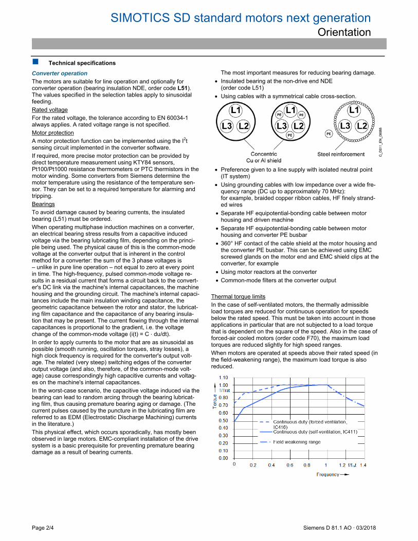
The most important measures for reducing bearing damage.
Insulated bearing at the non-drive end NDE (order code L51)
Using cables with a symmetrical cable cross-section.
Preference given to a line supply with isolated neutral point
(IT system)
Using grounding cables with low impedance over a wide fre-quency range (DC up to approximately 70 MHz): for example, braided copper ribbon cables, HF finely strand-ed wires
Separate HF equipotential-bonding cable between motor housing and driven machine
Separate HF equipotential-bonding cable between motor housing and converter PE busbar
360° HF contact of the cable shield at the motor housing and the converter PE busbar. This can be achieved using EMC screwed glands on the motor end and EMC shield clips at the converter, for example
Using motor reactors at the converter
Common-mode filters at the converter output
Thermal torque limits
In the case of self-ventilated motors, the thermally admissible load torques are reduced for continuous operation for speeds below the rated speed. This must be taken into account in those applications in particular that are not subjected to a load torque that is dependent on the square of the speed. Also in the case of forced-air cooled motors (order code F70), the maximum load torques are reduced slightly for high speed ranges.
When motors are operated at speeds above their rated speed (in the field-weakening range), the maximum load torque is also reduced.
SIMOTICS SD standard motors next generation Orientation
Siemens D 81.1 AO · 03/2018 Page 2/5
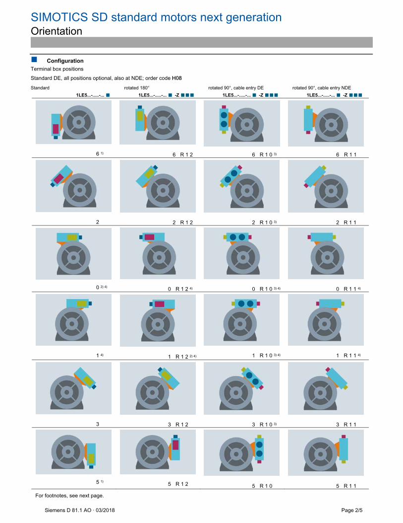
Configuration
Terminal box positions Standard DE, all positions optional, also at NDE; order code H08
Standard rotated 180° rotated 90°, cable entry DE rotated 90°, cable entry NDE
1LE5...-.....-... ■ 1LE5...-.....-... ■ -Z ■■■ 1LE5...-.....-... ■ -Z ■■■ 1LE5...-.....-... ■ -Z ■■■
6 1)
6 R 1 2
6 R 1 0 3)
6 R 1 1
2
2 R 1 2
2 R 1 0 3)
2 R 1 1
0 2) 4)
0 R 1 2 4)
0 R 1 0 3) 4)
0 R 1 1 4)
1 4)
1 R 1 2 2) 4)
1 R 1 0 3) 4)
1 R 1 1 4)
3
3 R 1 2
3 R 1 0 3)
3 R 1 1
5 1)
5 R 1 2
5 R 1 0
5 R 1 1
For footnotes, see next page.
SIMOTICS SD standard motors next generation Orientation
Page 2/6 Siemens D 81.1 AO · 03/2018
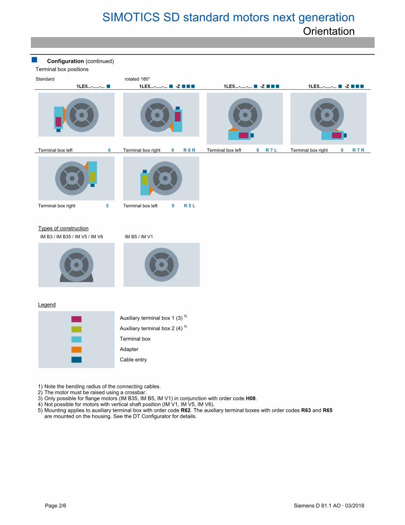
Configuration (continued)
Terminal box positions
Standard rotated 180°
1LE5...-.....-... ■ 1LE5...-.....-... ■ -Z ■■■ 1LE5...-.....-... ■ -Z ■■■ 1LE5...-.....-... ■ -Z ■■■
Terminal box left 6 Terminal box right 9 R 6 R Terminal box left 9 R 7 L Terminal box right 9 R 7 R
Terminal box right 5 Terminal box left 9 R 5 L
Types of construction
IM B3 / IM B35 / IM V5 / IM V6 IM B5 / IM V1
Legend
Auxiliary terminal box 1 (3) 5)
Auxiliary terminal box 2 (4) 5)
Terminal box
Adapter
Cable entry
1) Note the bending radius of the connecting cables. 2) The motor must be raised using a crossbar. 3) Only possible for flange motors (IM B35, IM B5, IM V1) in conjunction with order code H08. 4) Not possible for motors with vertical shaft position (IM V1, IM V5, IM V6). 5) Mounting applies to auxiliary terminal box with order code R62. The auxiliary terminal boxes with order codes R63 and R65
are mounted on the housing. See the DT Configurator for details.

SIMOTICS SD standard motors next generation Orientation
Siemens D 81.1 AO · 03/2018 Page 2/7
Technical specifications
Overview of technical specifications
This table lists the most important technical specifications. For more information and details, see catalog section 1 "Introduction".
Motor type SIMOTICS SD 1LE5 IEC low-voltage motors Connection types Star/delta connection
The connection type to be used can be established from the Article No. supplements for the required motor. Number of poles 2, 4, 6, 8
Frame sizes 400 ... 450
Rated power 355 ... 1000 kW
Frequencies 50 Hz and 60 Hz
Versions • IE3 (Premium Efficiency) • IE4 (Super Premium Efficiency)
Marking IEC 60034-30-1 IE3, IE4: 2, 4, 6 and 8-pole
Rated speed (synchronous speed)
750 ... 3600 rpm
Rated torque 1600 ... 8100 Nm
Insulation of the stator winding in accordance with EN 60034-1 (IEC 60034-1)
SD Add: Temperature class 155 (F), utilized to temperature class 130 (B) DURIGNIT IR 2000 insulation system SD Pro: Temperature class 155 (F), utilized to temperature class 155 (F) DURIGNIT IR 2000 insulation system
Degree of protection according to EN 60034-5 (IEC 60034-5)
IP55 as standard
Cooling according to EN 60034-6 (IEC 60034-6)
• Self-ventilated (IC411) • Forced-air cooled motors w/o ext. fan/fan cover (IC418) • Forced-air cooled (IC416)
Permissible coolant temperature and installation altitude
-20 ... +40 °C as standard, installation altitude up to 1000 m above sea level. See "Coolant temperature and installation altitude" in Catalog Section 1 "Introduction".
Standard voltages according to EN 60038 (IEC 60038)
50 Hz: 400 V, 500 V, 690 V The voltage to be used can be found in the "Selection and ordering data" for the required motor.
Type of construction according to EN 60034-7 (IEC 60034-7)
• Without flange: IM B3, IM V5 (on request), IM V6 (on request) • With flange: IM B5 with support foot, IM V1, IM B35
Paint finish Suitability of paint finish for climate group according to IEC 60721, Part 2-1
As standard: Color RAL 7030 stone gray See "Paint finish" in Catalog Section 1 "Introduction".
Vibration severity grade according to EN 60034-14 (IEC 60034-14)
Grade A (normal – without special vibration requirements) Optionally: Grade B (with special vibration requirements) See "Balance and vibration quantity" in Catalog Section 1 "Introduction".
Shaft extension according to DIN 748 (IEC 60072)
Balancing type: half-key balancing as standard See "Balance and vibration severity" in Catalog Section 1 "Introduction".
Sound pressure level according to EN ISO 1680 (tolerance +3 dB)
The sound pressure level is listed in the selection and ordering data for the required motor.
Weights The weight is listed in the selection and ordering data for the required motor.
Modular mounting concept Rotary pulse encoder, brake, separately driven fan or prepared for mountings
Consistent series concept • Terminal box obliquely partitioned and optionally rotatable through 4 x 90° • Bearings at DE and NDE are of identical design, reinforced bearings available as an option
Options See Article No. supplements and special versions
More information
For more information, please get in touch with your Siemens contact in the Regions or use the DT Configurator.
Contacts: www.siemens.com/automation/partner DT Configurator: www.siemens.com/dt-configurator
You can find out about certain technologies through Siemens con-tact partners worldwide.
Wherever possible, you will find a local contact for: Technical support Spare parts/repairs Service Training Marketing & Sales Technical consultation/engineering
You start by selecting a: country product or sector
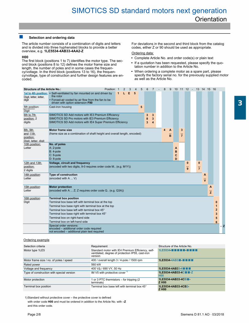
SIMOTICS SD standard motors next generation Orientation
Page 2/8 Siemens D 81.1 AO · 03/2018
Selection and ordering data
The article number consists of a combination of digits and letters and is divided into three hyphenated blocks to provide a better overview, e.g. 1LE5534-4AB33-4AA2-Z
H00 The first block (positions 1 to 7) identifies the motor type. The sec-ond block (positions 8 to 12) defines the motor frame size and length, the number of poles and in some cases the frequen-cy/voltage. In the third block (positions 13 to 16), the frequen-cy/voltage, type of construction and further design features are en-coded.
For deviations in the second and third block from the catalog codes, either Z or 90 should be used as appropriate.
Ordering data:
• Complete Article No. and order code(s) or plain text
• If a quotation has been requested, please specify the quo-tation number in addition to the Article No.
• When ordering a complete motor as a spare part, please specify the factory serial no. for the previously supplied motor as well as the Article No.
Structure of the Article No.: Position: 1 2 3 4 5 6 7 - 8 9 10 11 12 - 13 14 15 16
1st to 4th position: Digit, letter, letter, digit
• Self-ventilated by fan mounted on and driven by the rotor
• Forced-air cooled by air flow from the fan to be driven with option extension F90
1 L E 5
-
Z
5th position: Cast-iron housing 5 Digit
6th to 7th position: 2 digits
SIMOTICS SD Add motors with IE3 Premium Efficiency SIMOTICS SD Pro motors with IE3 Premium Efficiency SIMOTICS SD Add motors with IE4 Super Premium Efficiency
3 3 8 3 3 4
8th, 9th and 11th position: Digit, letter, digit
Motor frame size (frame size as a combination of shaft height and overall length, encoded)
4 A ... B
3 ... 7
10th position: Letter
No. of poles A: 2-pole B: 4-pole C: 6-pole D: 8-pole
A B C D
12th and 13th position: 2 digits
Voltage, circuit and frequency (encoded with two digits, 9-0 requires order code M.. (e.g. M1Y))
0 ... 9
0 ... 7
14th position: Letter
Type of construction (encoded with A ... V)
A ... V
15th position: Letter
Motor protection (encoded with A ... Z; Z requires order code Q.. (e.g. Q3A))
A ... Z
16th position: Digit
Terminal box position Terminal box base left with terminal box at the top
Terminal box base right with terminal box at the top
Terminal box base left with terminal box 45° Terminal box base right with terminal box 45°
Terminal box on right-hand side
Terminal box on left-hand side
0 1 2
3
5
6
Special order versions: encoded – additional order code required not encoded – additional plain text required
Ordering example
Selection criteria Requirement Structure of the Article No.
Motor type 1LE5 Standard motor with IE4 Premium Efficiency, self-ventilated, degree of protection IP55, cast-iron version
1LE5534-■■■■■-■■■■
Motor frame size / no. of poles / speed 400 / overall length 3 / 4-pole / 1500 rpm 1LE5534-4AB3■-■■■■
Rated power 560 kW
Voltage and frequency 400 V∆ / 690 VY, 50 Hz 1LE5534-4AB33-4■■■
Type of construction with special version IM V5 with protective cover 1) 1LE5534-4AB33-4C■■-Z
H00
Motor protection 1 or 3 PTC thermistors – for tripping (2 terminals)
1LE5534-4AB33-4CB■-Z H00
Terminal box position Terminal box base left with terminal box 45° 1LE5534-4AB33-4CB2-Z H00
1) Standard without protective cover – the protective cover is defined
with order code H00 and must be ordered in addition to the Article No. with –Z
and this order code.
3
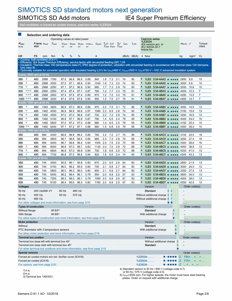
SIMOTICS SD standard motors next generation SIMOTICS SD Add motors IE4 Super Premium Efficiency
Self-ventilated or forced-air cooled motors, cast-iron series 1LE5534
Siemens D 81.1 AO · 03/2018 Page 2/9
Selection and ordering data Operating values at rated power Cast-iron series
1LE5534 IE4 version acc. to IEC 60034-30-1 Article No.
Prated 50 Hz
Frame size
nrated
Trated
ƞrated, 4/4
ƞrated, 3/4
ƞrated, 2/4
cosφrated, 4/4
IratedΔ
TLR/ Trated
ILR/ Irated
TB/ Trated
LpfA, LWA mIM B3 J Torque class
kW FS rpm Nm % % % A dB(A) dB(A) ▲ New kg kgm2 CL • Cooling: Self-ventilated (IC411) • Efficiency: IE4 Super Premium Efficiency, service factor with sinusoidal feeding (SF) 1.05 • Insulation: Thermal class 155 (temperature class F), IP55 degree of protection, utilization with sinusoidal feeding in accordance with thermal class 130 (tempera-
ture class B) • Optionally suitable for converter operation with insulated bearing (L51) for Uline≤480 V; Umotor≤500 V; UDC≤720 V – IVIC C advanced insulation system 2-pole: 3000 rpm at 50 Hz 560 3) 400 2988 1790 97.0 96.9 96.5 0.89 940 1.6 7.3 3.1 74 90 ▲ 1LE5 5 34-4AA3 ■- ■■■■2850 8.9 10 630 3) 400 2988 2000 97.0 97.1 96.8 0.90 1040 1.6 7.3 3.0 74 90 ▲ 1LE5 5 34-4AA5 ■-■■■■3000 9.8 10
710 4) 400 2988 2250 97.1 97.2 96.9 0.90 680 1.7 7.3 2.9 74 90 ▲ 1LE5 5 34-4AA7 ■-■■■■3200 10.8 10 800 3) 4) 5) 450 2990 2550 97.4 97.4 97.1 0.87 790 1.2 7.7 3.3 75 91 ▲ 1LE5 5 34-4BA3 ■-■■■■4000 12.3 7
900 3) 4) 5) 450 2988 2900 97.4 97.5 97.4 0.89 870 1.2 7.2 3.0 75 91 ▲ 1LE5 5 34-4BA5 ■-■■■■4250 13.5 7
1000 3) 4) 5) 450 2988 3200 97.4 97.6 97.6 0.90 950 1.2 7.0 2.7 75 91 ▲ 1LE5 5 34-4BA7 ■-■■■■4450 14.7 7
4-pole: 1500 rpm at 50 Hz 560 3) 400 1493 3600 96.9 97.0 96.6 0.86 970 2.2 7.5 3.1 72 88 ▲ 1LE5 5 34-4AB3 ■-■■■■3050 14.9 13 630 3) 400 1492 4050 96.8 96.9 96.6 0.87 1080 2.2 6.9 2.8 74 90 ▲ 1LE5 5 34-4AB5 ■-■■■■3150 15.6 13 710 4) 400 1492 4550 97.0 97.0 96.8 0.87 700 2.2 7.2 2.9 74 90 ▲ 1LE5 5 34-4AB7 ■-■■■■3250 16.9 13 800 4) 450 1492 5100 96.9 97.1 96.9 0.87 790 1.4 6.5 2.4 79 95 ▲ 1LE5 5 34-4BB3 ■-■■■■4000 24.0 10 900 4) 450 1492 5800 97.0 97.2 97.0 0.88 880 1.4 6.5 2.5 79 95 ▲ 1LE5 5 34-4BB5 ■-■■■■4150 25.4 10 1000 3) 4) 450 1492 6400 97.1 97.2 97.1 0.88 980 1.5 6.8 2.6 79 95 ▲ 1LE5 5 34-4BB7 ■-■■■■4350 28.0 10 6-pole: 1000 rpm at 50 Hz 450 400 994 4300 96.6 96.8 96.4 0.85 790 2.2 7.2 2.7 70 86 ▲ 1LE5 5 34-4AC3 ■-■■■■3100 25.5 16 500 400 994 4800 96.7 96.8 96.5 0.85 880 2.3 7.3 2.8 70 86 ▲ 1LE5 5 34-4AC5 ■-■■■■3250 27.4 16 560 400 994 5400 96.7 96.8 96.4 0.84 1000 2.4 7.5 2.9 70 86 ▲ 1LE5 5 34-4AC7 ■-■■■■3300 28.6 16 630 3) 450 995 6000 96.8 97.0 96.7 0.83 1130 2.0 7.0 2.8 72 88 ▲ 1LE5 5 34-4BC3 ■-■■■■4050 38.6 13 710 4) 450 994 6800 96.8 97.0 96.9 0.84 730 1.8 6.6 2.5 72 88 ▲ 1LE5 5 34-4BC5 ■-■■■■4200 41.0 13 800 4) 450 994 7700 96.8 97.0 96.8 0.84 820 1.8 6.6 2.4 74 90 ▲ 1LE5 5 34-4BC7 ■-■■■■4300 43.3 13 8-pole: 750 rpm at 50 Hz 355 400 744 4550 95.8 96.1 95.8 0.80 670 2.0 6.5 2.6 64 80 ▲ 1LE5 5 34-4AD3 ■-■■■■2850 21.9 13 400 400 744 5100 96.0 96.2 95.9 0.80 750 2.1 6.8 2.7 64 80 ▲ 1LE5 5 34-4AD5 ■-■■■■3050 24.5 13 450 400 744 5800 96.0 96.3 96.0 0.80 850 2.1 6.8 2.7 64 80 ▲ 1LE5 5 34-4AD7 ■-■■■■3250 27.5 13 500 450 745 6400 96.2 96.4 96.1 0.79 950 2.0 6.8 2.5 67 83 ▲ 1LE5 5 34-4BD3 ■-■■■■3800 34.0 13 560 450 745 7200 96.3 96.5 96.1 0.79 1060 2.0 6.9 2.6 67 83 ▲ 1LE5 5 34-4BD5 ■-■■■■4000 38.0 13 630 450 745 8100 96.4 96.6 96.3 0.80 1180 2.0 6.9 2.5 67 83 ▲ 1LE5 5 34-4BD7 ■-■■■■4250 42.5 13 Voltages Version Order code(s) 50 Hz 400 VΔ/690 VY 60 Hz 460 VΔ Standard 3 4 – 50 Hz 500 VΔ 60 Hz 575 VΔ Without additional charge 4 0 – 50 Hz 690 VΔ Without additional charge 4 7 – For other voltages and more information, see from page 2/15 . . . Types of construction Version Order code(s) Without flange IM B32) Standard A – With flange IM B52) With additional charge F – For other types of construction and more information, see from page 2/16 . . . Motor protection Version Order code(s) Without Standard A – PTC thermistor with 3 temperature sensors With additional charge B – For other motor protection and more information, see from page 2/18 . . . Terminal box position Version Order code(s) Terminal box base left with terminal box 45° Without additional charge 2 – Terminal box base right with terminal box 45° Standard 3 – For other terminal box positions and more information, see from page 2/19 Special versions Order code(s) Forced-air cooled motors w/o ext. fan/fan cover (IC418) 1LE5534- . . . . ・-Z F90+. . .+. . .+. . . Forced-air cooled (IC416) 1LE5534- . . . . ・-Z F70+. . .+. . .+. . . For options, see from page 2/20 1LE5534- . . . . ・-Z . .+. . .+. . .+ . . .
1) n.a. 2) n.a. 3) Terminal box 1XB1631.
4) Standard version is 50 Hz / 690 V (voltage code 4-7) or 60 Hz / 575 V (voltage code 4-0). 5) nmax=3000 rpm. For higher speeds, the motor must have steel bearing
plates. Order on request with additional charge.

SIMOTICS SD standard motors next generation SIMOTICS SD Add motors IE4 Super Premium Efficiency
Self-ventilated or forced-air cooled motors, cast-iron series 1LE5534
Page 2/10 Siemens D 81.1 AO · 03/2018
Selection and ordering data Operating values at rated power Cast-iron series
1LE5534 IE4 version acc. to IEC 60034-30-1 Article No.
Prated 60Hz
Frame size
nrated
Trated
ƞrated, 4/4
ƞrated, 3/4
ƞrated, 2/4
cosφrated, 4/4
IratedΔ
TLR/ Trated
ILR/ Irated
TB/ Trated
LpfA, LWA mIM B3 J Torque class
kW FS rpm Nm % % % A dB(A) dB(A) ▲ New kg kgm2 CL • Cooling: Self-ventilated (IC411) • Efficiency: IE4 Super Premium Efficiency, service factor with sinusoidal feeding (SF) 1.05 • Insulation: Thermal class 155 (temperature class F), IP55 degree of protection, utilization with sinusoidal feeding in accordance with thermal class 130 (tempera-
ture class B) • Optionally suitable for converter operation with insulated bearing (L51) for Uline≤480 V; Umotor≤500 V; UDC≤720 V – IVIC C advanced insulation system 2-pole: 3600 rpm at 60 Hz 616 3) 400 3588 1640 96.8 96.7 96.2 0.89 900 1.6 7.4 3.1 78 94 ▲ 1LE5 5 34-4AA3 ■- ■■■■2850 8.9 10 693 3) 400 3588 1840 97.0 96.9 96.4 0.90 1000 1.6 7.4 3.0 78 94 ▲ 1LE5 5 34-4AA5 ■-■■■■3000 9.8 10
781 3) 4) 400 3590 2100 97.1 97.0 96.5 0.89 910 1.8 7.5 3.2 78 94 ▲ 1LE5 5 34-4AA7 ■-■■■■3200 10.8 10 920 3) 4) 5) 450 3590 2450 97.3 97.3 96.8 0.88 1080 1.1 7.6 3.2 79 95 ▲ 1LE5 5 34-4BA3 ■ - ■ ■ ■ ■ 4000 12.3 7
1040 3) 4) 5) 450 3588 2750 97.4 97.4 97.0 0.89 1200 1.2 7.2 3.0 79 95 ▲ 1LE5 5 34-4BA5 ■ - ■ ■ ■ ■ 4250 13.5 7
1120 3) 4) 5) 450 3586 3000 97.4 97.6 97.3 0.90 1280 1.2 6.9 2.6 79 95 ▲ 1LE5 5 34-4BA7 ■ - ■ ■ ■ ■ 4450 14.7 7
4-pole: 1800 rpm at 60 Hz 644 3) 400 1793 3450 96.9 96.9 96.4 0.87 960 2.1 7.5 3.0 76 92 ▲ 1LE5 5 34-4AB3 ■-■■■■3050 14.9 13 725 3) 400 1792 3850 96.8 96.8 96.4 0.87 1080 2.1 6.9 2.7 78 94 ▲ 1LE5 5 34-4AB5 ■-■■■■3150 15.6 13 817 4) 400 1791 4350 96.9 97.0 96.7 0.88 960 1.9 6.8 2.5 78 94 ▲ 1LE5 5 34-4AB7 ■-■■■■3250 16.9 13 920 3) 4) 450 1792 4900 96.9 97.0 96.6 0.87 1100 1.3 6.3 2.3 83 99 ▲ 1LE5 5 34-4BB3 ■-■■■■4000 24.0 10 1040 3) 4) 450 1793 5500 97.1 97.1 96.7 0.87 1240 1.4 6.8 2.6 83 99 ▲ 1LE5 5 34-4BB5 ■-■■■■4150 25.4 10 1150 3) 4) 450 1792 6100 97.1 97.2 96.9 0.88 1350 1.4 6.7 2.4 83 99 ▲ 1LE5 5 34-4BB7 ■-■■■■4350 28.0 10 6-pole: 1200 rpm at 60 Hz 518 400 1194 4150 96.7 96.8 96.4 0.86 780 2.1 7.3 2.6 73 89 ▲ 1LE5 5 34-4AC3 ■-■■■■3100 25.5 16 575 400 1194 4600 96.8 96.9 96.5 0.86 870 2.2 7.4 2.7 73 89 ▲ 1LE5 5 34-4AC5 ■-■■■■3250 27.4 16 644 400 1194 5200 96.8 96.8 96.4 0.85 980 2.3 7.6 2.8 73 89 ▲ 1LE5 5 34-4AC7 ■-■■■■3300 28.6 16 725 3) 450 1195 5800 96.9 97.0 96.7 0.84 1120 1.9 7.0 2.6 75 91 ▲ 1LE5 5 34-4BC3 ■-■■■■4050 38.6 13 817 4) 450 1194 6500 96.9 97.1 96.9 0.84 1010 1.7 6.6 2.3 75 91 ▲ 1LE5 5 34-4BC5 ■-■■■■4200 41.0 13 920 3) 4) 450 1194 7400 96.9 97.0 96.7 0.84 1130 1.8 6.6 2.4 77 93 ▲ 1LE5 5 34-4BC7 ■-■■■■4300 43.3 13 8-pole: 900 rpm at 60 Hz 408 400 894 4350 95.9 96.1 95.8 0.81 660 1.9 6.5 2.5 67 83 ▲ 1LE5 5 34-4AD3 ■-■■■■2850 21.9 13 460 400 894 4900 96.1 96.2 95.8 0.81 740 1.9 6.8 2.6 67 83 ▲ 1LE5 5 34-4AD5 ■-■■■■3050 24.5 13 518 400 894 5500 96.2 96.3 96.0 0.81 830 2.0 6.8 2.7 67 83 ▲ 1LE5 5 34-4AD7 ■-■■■■3250 27.5 13 575 450 895 6100 96.3 96.4 96.0 0.80 940 1.9 6.8 2.4 70 86 ▲ 1LE5 5 34-4BD3 ■-■■■■3800 34.0 13 644 450 895 6900 96.4 96.5 96.1 0.80 1050 1.9 6.9 2.5 70 86 ▲ 1LE5 5 34-4BD5 ■-■■■■4000 38.0 13 725 450 895 7700 96.5 96.6 96.3 0.81 1160 1.9 6.9 2.4 70 86 ▲ 1LE5 5 34-4BD7 ■-■■■■4250 42.5 13 Voltages Version Order code(s) 50 Hz 400 VΔ/690 VY 60 Hz 460 VΔ Standard 3 4 – 50 Hz 500 VΔ 60 Hz 575 VΔ Without additional charge 4 0 – 50 Hz 690 VΔ Without additional charge 4 7 – For other voltages and more information, see from page 2/15 . . . Types of construction Version Order code(s) Without flange IM B32) Standard A – With flange IM B52) With additional charge F – For other types of construction and more information, see from page 2/16 . . . Motor protection Version Order code(s) Without Standard A – PTC thermistor with 3 temperature sensors With additional charge B – For other motor protection and more information, see from page 2/18 . . . Terminal box position Version Order code(s) Terminal box base left with terminal box 45° Without additional charge 2 –
Terminal box base right with terminal box 45° Standard 3 –
For other terminal box positions and more information, see from page 2/19 Special versions Order code(s) Forced-air cooled motors w/o ext. fan/fan cover (IC418) 1LE5534- . . . . ・-Z F90+. . .+. . .+. . . Forced-air cooled (IC416) 1LE5534- . . . . ・-Z F70+. . .+. . .+. . . For options, see from page 2/20 1LE5534- . . . . ・-Z . .+. . .+. . .+ . . .
1) n.a. 2) n.a. 3) Terminal box 1XB1631.
4) Standard version is 50 Hz / 690 V (voltage code 4-7) or 60 H z / 575 V (voltage code 4-0). 5) Version only possible with steel bearing plates. Order on request with additional charge.
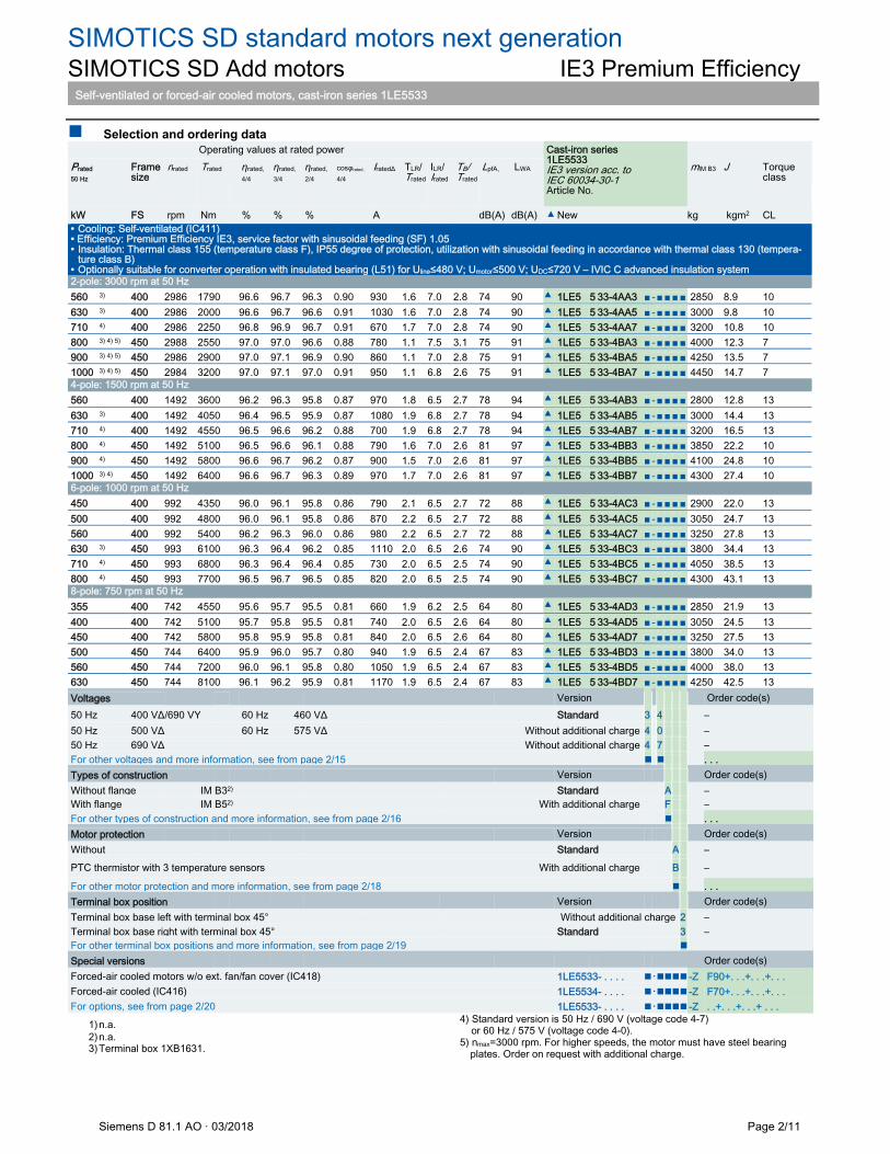
SIMOTICS SD standard motors next generation SIMOTICS SD Add motors IE3 Premium Efficiency
Self-ventilated or forced-air cooled motors, cast-iron series 1LE5533
Siemens D 81.1 AO · 03/2018 Page 2/11
Selection and ordering data Operating values at rated power Cast-iron series
1LE5533 IE3 version acc. to IEC 60034-30-1 Article No.
Prated 50 Hz
Frame size
nrated
Trated
ƞrated, 4/4
ƞrated, 3/4
ƞrated, 2/4
cosφrated, 4/4
IratedΔ
TLR/ Trated
ILR/ Irated
TB/ Trated
LpfA, LWA mIM B3 J Torque class
kW FS rpm Nm % % % A dB(A) dB(A) ▲ New kg kgm2 CL • Cooling: Self-ventilated (IC411) • Efficiency: Premium Efficiency IE3, service factor with sinusoidal feeding (SF) 1.05 • Insulation: Thermal class 155 (temperature class F), IP55 degree of protection, utilization with sinusoidal feeding in accordance with thermal class 130 (tempera-
ture class B) • Optionally suitable for converter operation with insulated bearing (L51) for Uline≤480 V; Umotor≤500 V; UDC≤720 V – IVIC C advanced insulation system 2-pole: 3000 rpm at 50 Hz 560 3) 400 2986 1790 96.6 96.7 96.3 0.90 930 1.6 7.0 2.8 74 90 ▲ 1LE5 5 33-4AA3 ■-■■■■2850 8.9 10 630 3) 400 2986 2000 96.6 96.7 96.6 0.91 1030 1.6 7.0 2.8 74 90 ▲ 1LE5 5 33-4AA5 ■-■■■■3000 9.8 10
710 4) 400 2986 2250 96.8 96.9 96.7 0.91 670 1.7 7.0 2.8 74 90 ▲ 1LE5 5 33-4AA7 ■-■■■■3200 10.8 10 800 3) 4) 5) 450 2988 2550 97.0 97.0 96.6 0.88 780 1.1 7.5 3.1 75 91 ▲ 1LE5 5 33-4BA3 ■-■■■■4000 12.3 7
900 3) 4) 5) 450 2986 2900 97.0 97.1 96.9 0.90 860 1.1 7.0 2.8 75 91 ▲ 1LE5 5 33-4BA5 ■-■■■■4250 13.5 7
1000 3) 4) 5) 450 2984 3200 97.0 97.1 97.0 0.91 950 1.1 6.8 2.6 75 91 ▲ 1LE5 5 33-4BA7 ■-■■■■4450 14.7 7
4-pole: 1500 rpm at 50 Hz 560 400 1492 3600 96.2 96.3 95.8 0.87 970 1.8 6.5 2.7 78 94 ▲ 1LE5 5 33-4AB3 ■-■■■■2800 12.8 13 630 3) 400 1492 4050 96.4 96.5 95.9 0.87 1080 1.9 6.8 2.7 78 94 ▲ 1LE5 5 33-4AB5 ■-■■■■3000 14.4 13 710 4) 400 1492 4550 96.5 96.6 96.2 0.88 700 1.9 6.8 2.7 78 94 ▲ 1LE5 5 33-4AB7 ■-■■■■3200 16.5 13 800 4) 450 1492 5100 96.5 96.6 96.1 0.88 790 1.6 7.0 2.6 81 97 ▲ 1LE5 5 33-4BB3 ■-■■■■3850 22.2 10 900 4) 450 1492 5800 96.6 96.7 96.2 0.87 900 1.5 7.0 2.6 81 97 ▲ 1LE5 5 33-4BB5 ■-■■■■4100 24.8 10 1000 3) 4) 450 1492 6400 96.6 96.7 96.3 0.89 970 1.7 7.0 2.6 81 97 ▲ 1LE5 5 33-4BB7 ■-■■■■4300 27.4 10 6-pole: 1000 rpm at 50 Hz 450 400 992 4350 96.0 96.1 95.8 0.86 790 2.1 6.5 2.7 72 88 ▲ 1LE5 5 33-4AC3 ■-■■■■2900 22.0 13 500 400 992 4800 96.0 96.1 95.8 0.86 870 2.2 6.5 2.7 72 88 ▲ 1LE5 5 33-4AC5 ■-■■■■3050 24.7 13 560 400 992 5400 96.2 96.3 96.0 0.86 980 2.2 6.5 2.7 72 88 ▲ 1LE5 5 33-4AC7 ■-■■■■3250 27.8 13 630 3) 450 993 6100 96.3 96.4 96.2 0.85 1110 2.0 6.5 2.6 74 90 ▲ 1LE5 5 33-4BC3 ■-■■■■3800 34.4 13 710 4) 450 993 6800 96.3 96.4 96.4 0.85 730 2.0 6.5 2.5 74 90 ▲ 1LE5 5 33-4BC5 ■-■■■■4050 38.5 13 800 4) 450 993 7700 96.5 96.7 96.5 0.85 820 2.0 6.5 2.5 74 90 ▲ 1LE5 5 33-4BC7 ■-■■■■4300 43.1 13 8-pole: 750 rpm at 50 Hz 355 400 742 4550 95.6 95.7 95.5 0.81 660 1.9 6.2 2.5 64 80 ▲ 1LE5 5 33-4AD3 ■-■■■■2850 21.9 13 400 400 742 5100 95.7 95.8 95.5 0.81 740 2.0 6.5 2.6 64 80 ▲ 1LE5 5 33-4AD5 ■-■■■■3050 24.5 13 450 400 742 5800 95.8 95.9 95.8 0.81 840 2.0 6.5 2.6 64 80 ▲ 1LE5 5 33-4AD7 ■-■■■■3250 27.5 13 500 450 744 6400 95.9 96.0 95.7 0.80 940 1.9 6.5 2.4 67 83 ▲ 1LE5 5 33-4BD3 ■-■■■■3800 34.0 13 560 450 744 7200 96.0 96.1 95.8 0.80 1050 1.9 6.5 2.4 67 83 ▲ 1LE5 5 33-4BD5 ■-■■■■4000 38.0 13 630 450 744 8100 96.1 96.2 95.9 0.81 1170 1.9 6.5 2.4 67 83 ▲ 1LE5 5 33-4BD7 ■-■■■■4250 42.5 13 Voltages Version Order code(s) 50 Hz 400 VΔ/690 VY 60 Hz 460 VΔ Standard 3 4 – 50 Hz 500 VΔ 60 Hz 575 VΔ Without additional charge 4 0 – 50 Hz 690 VΔ Without additional charge 4 7 – For other voltages and more information, see from page 2/15 . . . Types of construction Version Order code(s) Without flange IM B32) Standard A – With flange IM B52) With additional charge F – For other types of construction and more information, see from page 2/16 . . . Motor protection Version Order code(s) Without Standard A –
PTC thermistor with 3 temperature sensors With additional charge B –
For other motor protection and more information, see from page 2/18 . . . Terminal box position Version Order code(s) Terminal box base left with terminal box 45° Without additional charge 2 – Terminal box base right with terminal box 45° Standard 3 – For other terminal box positions and more information, see from page 2/19 Special versions Order code(s) Forced-air cooled motors w/o ext. fan/fan cover (IC418) 1LE5533- . . . . ・-Z F90+. . .+. . .+. . . Forced-air cooled (IC416) 1LE5534- . . . . ・-Z F70+. . .+. . .+. . . For options, see from page 2/20 1LE5533- . . . . ・-Z . .+. . .+. . .+ . . .
1) n.a. 2) n.a. 3) Terminal box 1XB1631.
4) Standard version is 50 Hz / 690 V (voltage code 4-7) or 60 Hz / 575 V (voltage code 4-0). 5) nmax=3000 rpm. For higher speeds, the motor must have steel bearing
plates. Order on request with additional charge.
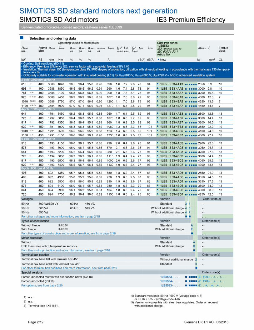
SIMOTICS SD standard motors next generation SIMOTICS SD Add motors IE3 Premium Efficiency
Self-ventilated or forced-air cooled motors, cast-iron series 1LE5533
Page 2/12 Siemens D 81.1 AO · 03/2018
Selection and ordering data Operating values at rated power Cast-iron series
1LE5533 IE3 version acc. to IEC 60034-30-1 Article No.
Prated 60Hz
Frame size
nrated
Trated
ƞrated, 4/4
ƞrated, 3/4
ƞrated, 2/4
cosφrated, 4/4
IratedΔ
TLR/ Trated
ILR/ Irated
TB/ Trated
LpfA, LWA mIM B3 J Torque class
kW FS rpm Nm % % % A dB(A) dB(A) ▲ New kg kgm2 CL • Cooling: Self-ventilated (IC411) • Efficiency: Premium Efficiency IE3, service factor with sinusoidal feeding (SF) 1.05 • Insulation: Thermal class 155 (temperature class F), IP55 degree of protection, utilization with sinusoidal feeding in accordance with thermal class 130 (tempera-
ture class B) • Optionally suitable for converter operation with insulated bearing (L51) for Uline≤480 V; Umotor≤500 V; UDC≤720 V – IVIC C advanced insulation system 2-pole: 3600 rpm at 60 Hz 616 3) 400 3586 1640 96.5 96.4 95.8 0.90 890 1.6 7.2 2.8 78 94 ▲ 1LE5 5 33-4AA3 ■-■■■■2850 8.9 10 693 3) 400 3586 1850 96.5 96.5 96.2 0.91 990 1.6 7.1 2.8 78 94 ▲ 1LE5 5 33-4AA5 ■ - ■ ■ ■ ■ 3000 9.8 10
781 3) 4) 400 3588 2100 96.8 96.8 96.3 0.90 900 1.8 7.3 3.1 78 94 ▲ 1LE5 5 33-4AA7 ■ - ■ ■ ■ ■ 3200 10.8 10 920 3) 4) 5) 450 3588 2450 96.9 96.9 96.5 0.89 1070 1.0 7.5 3.0 79 95 ▲ 1LE5 5 33-4BA3 ■ - ■ ■ ■ ■ 4000 12.3 7
1040 3) 4) 5) 450 3586 2750 97.0 97.0 96.6 0.90 1200 1.1 7.0 2.8 79 95 ▲ 1LE5 5 33-4BA5 ■ - ■ ■ ■ ■ 4250 13.5 7
1120 3) 4) 5) 450 3584 3000 97.0 97.1 96.9 0.91 1270 1.1 6.8 2.5 79 95 ▲ 1LE5 5 33-4BA7 ■ - ■ ■ ■ ■ 4450 14.7 7
4-pole: 1800 rpm at 60 Hz 644 400 1791 3450 96.2 96.3 95.5 0.88 950 1.7 6.4 2.5 82 98 ▲ 1LE5 5 33-4AB3 ■-■■■■2800 12.8 13 725 3) 400 1792 3850 96.4 96.3 95.7 0.88 1070 1.8 6.8 2.7 82 98 ▲ 1LE5 5 33-4AB5 ■-■■■■3000 14.4 13 817 4) 400 1792 4350 96.5 96.4 95.9 0.89 960 1.8 6.8 2.5 82 98 ▲ 1LE5 5 33-4AB7 ■-■■■■3200 16.5 13 920 3) 4) 450 1791 4900 96.3 96.3 95.8 0.89 1080 1.3 6.5 2.3 85 101 ▲ 1LE5 5 33-4BB3 ■-■■■■3850 22.2 10 1040 3) 4) 450 1791 5500 96.5 96.5 95.9 0.88 1230 1.4 6.8 2.5 85 101 ▲ 1LE5 5 33-4BB5 ■-■■■■4100 24.8 10 1150 3) 4) 450 1791 6100 96.6 96.6 96.1 0.90 1330 1.6 6.8 2.5 85 101 ▲ 1LE5 5 33-4BB7 ■-■■■■4300 27.4 10 6-pole: 1200 rpm at 60 Hz 518 400 1193 4150 96.0 96.1 95.7 0.86 790 2.0 6.4 2.6 75 91 ▲ 1LE5 5 33-4AC3 ■-■■■■2900 22.0 13 575 400 1193 4600 96.0 96.1 95.8 0.86 870 2.1 6.5 2.6 75 91 ▲ 1LE5 5 33-4AC5 ■-■■■■3050 24.7 13 644 400 1193 5200 96.2 96.4 96.0 0.86 980 2.1 6.5 2.6 75 91 ▲ 1LE5 5 33-4AC7 ■-■■■■3250 27.8 13 725 3) 450 1194 5800 96.3 96.3 96.1 0.85 1110 1.9 6.4 2.4 77 93 ▲ 1LE5 5 33-4BC3 ■-■■■■3800 34.4 13 817 4) 450 1193 6500 96.3 96.4 96.4 0.85 1000 2.0 6.6 2.6 77 93 ▲ 1LE5 5 33-4BC5 ■-■■■■4050 38.5 13 920 3) 4) 450 1193 7400 96.5 96.7 96.4 0.85 1130 1.9 6.6 2.4 77 93 ▲ 1LE5 5 33-4BC7 ■-■■■■4300 43.1 13 8-pole: 900 rpm at 60 Hz 408 400 892 4350 95.7 95.8 95.5 0.82 650 1.8 6.2 2.4 67 83 ▲ 1LE5 5 33-4AD3 ■-■■■■2850 21.9 13 460 400 892 4900 95.8 95.9 95.6 0.82 730 1.9 6.5 2.5 67 83 ▲ 1LE5 5 33-4AD5 ■-■■■■3050 24.5 13 518 400 892 5500 95.9 96.0 95.8 0.82 830 1.9 6.5 2.6 67 83 ▲ 1LE5 5 33-4AD7 ■-■■■■3250 27.5 13 575 450 894 6100 96.0 96.1 95.7 0.81 930 1.8 6.5 2.3 70 86 ▲ 1LE5 5 33-4BD3 ■-■■■■3800 34.0 13 644 450 894 6900 96.1 96.2 95.8 0.81 1040 1.8 6.5 2.4 70 86 ▲ 1LE5 5 33-4BD5 ■-■■■■4000 38.0 13 725 450 894 7700 96.2 96.4 96.0 0.82 1150 1.8 6.5 2.4 70 86 ▲ 1LE5 5 33-4BD7 ■-■■■■4250 42.5 13 Voltages Version Order code(s) 50 Hz 400 VΔ/690 VY 60 Hz 460 VΔ Standard 3 4 – 50 Hz 500 VΔ 60 Hz 575 VΔ Without additional charge 4 0 – 50 Hz 690 VΔ Without additional charge 4 7 – For other voltages and more information, see from page 2/15 . . . Types of construction Version Order code(s) Without flange IM B32) Standard A – With flange IM B52) With additional charge F – For other types of construction and more information, see from page 2/16 . . . Motor protection Version Order code(s) Without Standard A – PTC thermistor with 3 temperature sensors With additional charge B – For other motor protection and more information, see from page 2/18 . . . Terminal box position Version Order code(s) Terminal box base left with terminal box 45° Without additional charge 2 – Terminal box base right with terminal box 45° Standard 3 – For other terminal box positions and more information, see from page 2/19 Special versions Order code(s) Forced-air cooled motors w/o ext. fan/fan cover (IC418) 1LE5533- . . . . ・-Z F90+. . .+. . .+. . . Forced-air cooled (IC416) 1LE5534- . . . . ・-Z F70+. . .+. . .+. . . For options, see from page 2/20 1LE5533- . . . . ・-Z . .+. . .+. . .+ . . .
1) n.a. 2) n.a. 3) Terminal box 1XB1631.
4) Standard version is 50 Hz / 690 V (voltage code 4-7) or 60 Hz / 575 V (voltage code 4-0). 5) Version only possible with steel bearing plates. Order on request with additional charge.
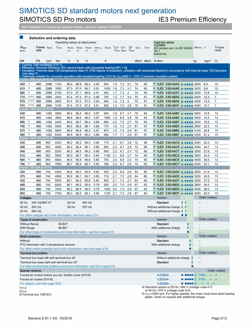
SIMOTICS SD standard motors next generation SIMOTICS SD Pro motors IE3 Premium Efficiency
Self-ventilated or forced-air cooled motors, cast-iron series 1LE5583
Siemens D 81.1 AO · 03/2018 Page 2/13
Selection and ordering data Operating values at rated power Cast-iron series
1LE5583 IE3 version acc. to IEC 60034-30-1 Article No.
Prated 50 Hz
Frame size
nrated
Trated
ƞrated, 4/4
ƞrated, 3/4
ƞrated, 2/4
cosφrated, 4/4
IratedΔ
TLR/ Trated
ILR/ Irated
TB/ Trated
LpfA, LWA mIM B3 J Torque class
kW FS rpm Nm % % % A dB(A) dB(A) ▲ New kg kgm2 CL • Cooling: Self-ventilated (IC411) • Efficiency: Premium Efficiency IE3, service factor with sinusoidal feeding (SF) 1.05 • Insulation: Thermal class 155 (temperature class F), IP55 degree of protection, utilization with sinusoidal feeding in accordance with thermal class 155 (tempera-
ture class F) • Optionally suitable for converter operation with insulated bearing (L51) for Uline≤690 V – IVIC C premium insulation system
•
2-pole: 3000 rpm at 50 Hz 545 3) 400 2988 1740 96.9 96.9 96.4 0.90 900 1.6 7.3 3.1 74 90 ▲ 1LE5 5 83-4AA3 ■-■■■■2850 8.9 10 610 3) 400 2988 1950 97.0 97.0 96.7 0.91 1000 1.6 7.3 3.1 74 90 ▲ 1LE5 5 83-4AA5 ■-■■■■3000 9.8 10
680 4) 400 2988 2150 97.0 97.1 96.8 0.91 640 1.7 7.3 3 74 90 ▲ 1LE5 5 83-4AA7 ■-■■■■3200 10.8 10 775 3) 4) 5) 450 2990 2500 97.4 97.4 97.0 0.88 760 1.2 7.7 3.4 75 91 ▲ 1LE5 5 83-4BA3 ■-■■■■4000 12.3 7
875 3) 4) 5) 450 2988 2800 97.4 97.5 97.3 0.90 840 1.2 7.2 3 75 91 ▲ 1LE5 5 83-4BA5 ■-■■■■4250 13.5 7
970 3) 4) 5) 450 2986 3100 97.4 97.5 97.4 0.91 920 1.2 7.0 2.8 75 91 ▲ 1LE5 5 83-4BA7 ■-■■■■4450 14.7 7
4-pole: 1500 rpm at 50 Hz 545 400 1492 3500 96.4 96.4 96.0 0.87 940 1.8 6.7 2.7 78 94 ▲ 1LE5 5 83-4AB3 ■-■■■■2800 12.8 13 615 400 1492 3950 96.6 96.6 96.2 0.87 1060 1.9 6.9 2.8 78 94 ▲ 1LE5 5 83-4AB5 ■-■■■■3000 14.4 13 690 4) 400 1492 4400 96.6 96.7 96.4 0.88 680 2.0 7.0 2.7 78 94 ▲ 1LE5 5 83-4AB7 ■-■■■■3200 16.5 13 785 4) 450 1492 5000 96.6 96.6 96.1 0.88 770 1.6 7.2 2.7 81 97 ▲ 1LE5 5 83-4BB3 ■-■■■■3850 22.2 10 875 4) 450 1492 5600 96.8 96.8 96.3 0.87 870 1.5 7.2 2.6 81 97 ▲ 1LE5 5 83-4BB5 ■-■■■■4100 24.8 10 980 4) 450 1492 6300 96.9 96.9 96.5 0.89 950 1.7 7.1 2.6 81 97 ▲ 1LE5 5 83-4BB7 ■-■■■■4300 27.4 10 6-pole: 1000 rpm at 50 Hz 435 400 993 4200 96.2 96.3 96.0 0.85 770 2.1 6.7 2.8 72 88 ▲ 1LE5 5 83-4AC3 ■-■■■■2900 22.0 13 485 400 993 4650 96.2 96.4 96.1 0.86 850 2.2 6.7 2.8 72 88 ▲ 1LE5 5 83-4AC5 ■-■■■■3050 24.7 13 545 400 993 5200 96.3 96.5 96.2 0.86 950 2.2 6.7 2.7 72 88 ▲ 1LE5 5 83-4AC7 ■-■■■■3250 27.8 13 615 450 993 5900 96.5 96.7 96.4 0.84 1100 2.1 6.6 2.7 74 90 ▲ 1LE5 5 83-4BC3 ■-■■■■3800 34.4 13 690 4) 450 993 6600 96.6 96.8 96.6 0.85 700 2.0 6.8 2.5 74 90 ▲ 1LE5 5 83-4BC5 ■-■■■■4050 38.5 13 780 4) 450 993 7500 96.7 96.9 96.7 0.85 790 2.0 6.7 2.6 74 90 ▲ 1LE5 5 83-4BC7 ■-■■■■4300 43.1 13 8-pole: 750 rpm at 50 Hz 335 400 744 4300 95.8 96.0 95.6 0.80 630 2.0 6.9 2.6 64 80 ▲ 1LE5 5 83-4AD3 ■-■■■■2850 21.9 13 375 400 744 4800 95.9 96.1 95.7 0.80 710 2.1 7.2 2.8 64 80 ▲ 1LE5 5 83-4AD5 ■-■■■■3050 24.5 13 425 400 744 5500 96.1 96.2 95.8 0.80 800 2.1 7.2 2.7 64 80 ▲ 1LE5 5 83-4AD7 ■-■■■■3250 27.5 13 485 450 745 6200 96.1 96.2 95.9 0.79 920 2.0 7.0 2.6 67 83 ▲ 1LE5 5 83-4BD3 ■-■■■■3800 34.0 13 545 450 745 7000 96.2 96.4 96.0 0.79 1040 2.0 7.0 2.6 67 83 ▲ 1LE5 5 83-4BD5 ■-■■■■4000 38.0 13 600 450 745 7700 96.3 96.5 96.1 0.80 1120 2.1 7.3 2.6 67 83 ▲ 1LE5 5 83-4BD7 ■-■■■■4250 42.5 13 Voltages Version Order code(s)
50 Hz 400 VΔ/690 VY 60 Hz 460 VΔ Standard 3 4 – 50 Hz 500 VΔ 60 Hz 575 VΔ Without additional charge 4 0 – 50 Hz 690 VΔ Without additional charge 4 7 – For other voltages and more information, see from page 2/15 . . . Types of construction Version Order code(s) Without flange IM B32) Standard A – With flange IM B52) With additional charge F – For other types of construction and more information, see from page 2/16 . . . Motor protection Version Order code(s) Without Standard A – PTC thermistor with 3 temperature sensors With additional charge B – For other motor protection and more information, see from page 2/18 . . . Terminal box position Version Order code(s)
Terminal box base left with terminal box 45° Without additional charge 2 – Terminal box base right with terminal box 45° Standard 3 – For other terminal box positions and more information, see from page 2/19 Special versions Order code(s) Forced-air cooled motors w/o ext. fan/fan cover (IC418) 1LE5583- . . . . ・-Z F90+. . .+. . .+. . . Forced-air cooled (IC416) 1LE5534- . . . . ・-Z F70+. . .+. . .+. . . For options, see from page 2/20 1LE5583- . . . . ・-Z . .+. . .+. . .+ . . .
1) n.a. 2) n.a. 3) Terminal box 1XB1631.
4) Standard version is 50 Hz / 690 V (voltage code 4-7) or 60 Hz / 575 V (voltage code 4-0). 5) nmax=3000 rpm. For higher speeds, the motor must have steel bearing
plates. Order on request with additional charge.
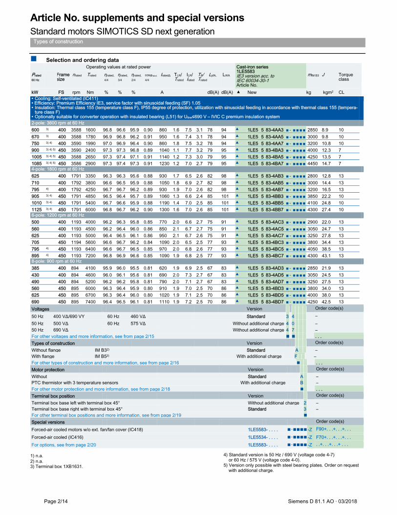
Article No. supplements and special versions Standard motors SIMOTICS SD next generation
Types of construction
Page 2/14 Siemens D 81.1 AO · 03/2018
Selection and ordering data Operating values at rated power Cast-iron series
1LE5583 IE3 version acc. to IEC 60034-30-1 Article No.
Prated 60 Hz
Frame size
nrated
Trated
ƞrated, 4/4
ƞrated, 3/4
ƞrated, 2/4
cosφrated, 4/4
IratedΔ
TLR/ Trated
ILR/ Irated
TB/ Trated
LpfA, LWA mIM B3 J Torque class
kW FS rpm Nm % % % A dB(A) dB(A) ▲ New kg kgm2 CL • Cooling: Self-ventilated (IC411) • Efficiency: Premium Efficiency IE3, service factor with sinusoidal feeding (SF) 1.05 • Insulation: Thermal class 155 (temperature class F), IP55 degree of protection, utilization with sinusoidal feeding in accordance with thermal class 155 (tempera-
ture class F) • Optionally suitable for converter operation with insulated bearing (L51) for Uline≤690 V – IVIC C premium insulation system
2-pole: 3600 rpm at 60 Hz 600 3) 400 3588 1600 96.8 96.6 95.9 0.90 860 1.6 7.5 3.1 78 94 ▲ 1LE5 5 83-4AA3 ■-■■■■2850 8.9 10 670 3) 400 3588 1780 96.9 96.8 96.2 0.91 950 1.6 7.4 3.1 78 94 ▲ 1LE5 5 83-4AA5 ■-■■■■3000 9.8 10
750 3) 4) 400 3590 1990 97.0 96.9 96.4 0.90 860 1.8 7.5 3.2 78 94 ▲ 1LE5 5 83-4AA7 ■-■■■■3200 10.8 10 900 3) 4) 5) 450 3590 2400 97.3 97.3 96.8 0.89 1040 1.1 7.7 3.2 79 95 ▲ 1LE5 5 83-4BA3 ■-■■■■4000 12.3 7
1005 3) 4) 5) 450 3588 2650 97.3 97.4 97.1 0.91 1140 1.2 7.3 3.0 79 95 ▲ 1LE5 5 83-4BA5 ■-■■■■4250 13.5 7
1085 3) 4) 5) 450 3586 2900 97.3 97.4 97.3 0.91 1230 1.2 7.0 2.7 79 95 ▲ 1LE5 5 83-4BA7 ■-■■■■4450 14.7 7
4-pole: 1800 rpm at 60 Hz 625 400 1791 3350 96.3 96.3 95.6 0.88 930 1.7 6.5 2.6 82 98 ▲ 1LE5 5 83-4AB3 ■-■■■■2800 12.8 13 710 400 1792 3800 96.6 96.5 95.9 0.88 1050 1.8 6.9 2.7 82 98 ▲ 1LE5 5 83-4AB5 ■-■■■■3000 14.4 13 795 4) 400 1792 4250 96.7 96.7 96.2 0.89 930 1.9 7.0 2.6 82 98 ▲ 1LE5 5 83-4AB7 ■-■■■■3200 16.5 13 905 3) 4) 450 1791 4850 96.5 96.4 95.7 0.89 1060 1.3 6.6 2.4 85 101 ▲ 1LE5 5 83-4BB3 ■-■■■■3850 22.2 10 1010 3) 4) 450 1791 5400 96.7 96.6 95.9 0.88 1190 1.4 7.0 2.5 85 101 ▲ 1LE5 5 83-4BB5 ■-■■■■4100 24.8 10 1125 3) 4) 450 1791 6000 96.8 96.7 96.2 0.90 1300 1.6 7.0 2.6 85 101 ▲ 1LE5 5 83-4BB7 ■-■■■■4300 27.4 10 6-pole: 1200 rpm at 60 Hz 500 400 1193 4000 96.2 96.3 95.8 0.85 770 2.0 6.6 2.7 75 91 ▲ 1LE5 5 83-4AC3 ■-■■■■2900 22.0 13 560 400 1193 4500 96.2 96.4 96.0 0.86 850 2.1 6.7 2.7 75 91 ▲ 1LE5 5 83-4AC5 ■-■■■■3050 24.7 13 625 400 1193 5000 96.4 96.5 96.1 0.86 950 2.1 6.7 2.6 75 91 ▲ 1LE5 5 83-4AC7 ■-■■■■3250 27.8 13 705 450 1194 5600 96.6 96.7 96.2 0.84 1090 2.0 6.5 2.5 77 93 ▲ 1LE5 5 83-4BC3 ■-■■■■3800 34.4 13 795 4) 450 1193 6400 96.6 96.7 96.5 0.85 970 2.0 6.8 2.6 77 93 ▲ 1LE5 5 83-4BC5 ■-■■■■4050 38.5 13 895 4) 450 1193 7200 96.8 96.9 96.6 0.85 1090 1.9 6.8 2.5 77 93 ▲ 1LE5 5 83-4BC7 ■-■■■■4300 43.1 13 8-pole: 900 rpm at 60 Hz 385 400 894 4100 95.9 96.0 95.5 0.81 620 1.9 6.9 2.5 67 83 ▲ 1LE5 5 83-4AD3 ■-■■■■2850 21.9 13 430 400 894 4600 96.0 96.1 95.6 0.81 690 2.0 7.3 2.7 67 83 ▲ 1LE5 5 83-4AD5 ■-■■■■3050 24.5 13 490 400 894 5200 96.2 96.2 95.8 0.81 790 2.0 7.1 2.7 67 83 ▲ 1LE5 5 83-4AD7 ■-■■■■3250 27.5 13 560 450 895 6000 96.3 96.4 95.9 0.80 910 1.9 7.0 2.5 70 86 ▲ 1LE5 5 83-4BD3 ■-■■■■3800 34.0 13 625 450 895 6700 96.3 96.4 96.0 0.80 1020 1.9 7.1 2.5 70 86 ▲ 1LE5 5 83-4BD5 ■-■■■■4000 38.0 13 690 450 895 7400 96.4 96.5 96.1 0.81 1110 1.9 7.2 2.5 70 86 ▲ 1LE5 5 83-4BD7 ■-■■■■4250 42.5 13 Voltages Version Order code(s)
50 Hz 400 VΔ/690 VY 60 Hz 460 VΔ Standard 3 4 – 50 Hz 500 VΔ 60 Hz 575 VΔ Without additional charge 4 0 – 50 Hz 690 VΔ Without additional charge 4 7 – For other voltages and more information, see from page 2/15 . . . Types of construction Version Order code(s) Without flange IM B32) Standard A – With flange IM B52) With additional charge F – For other types of construction and more information, see from page 2/16 . . . Motor protection Version Order code(s) Without Standard A – PTC thermistor with 3 temperature sensors With additional charge B – For other motor protection and more information, see from page 2/18 . . . Terminal box position Version Order code(s) Terminal box base left with terminal box 45° Without additional charge 2 – Terminal box base right with terminal box 45° Standard 3 – For other terminal box positions and more information, see from page 2/19 Special versions Order code(s)
Forced-air cooled motors w/o ext. fan/fan cover (IC418) 1LE5583- . . . . ・-Z F90+. . .+. . .+. . .
Forced-air cooled (IC416) 1LE5534- . . . . ・-Z F70+. . .+. . .+. . . For options, see from page 2/20 1LE5583- . . . . ・-Z . .+. . .+. . .+ . . .
1) n.a. 2) n.a. 3) Terminal box 1XB1631.
4) Standard version is 50 Hz / 690 V (voltage code 4-7) or 60 Hz / 575 V (voltage code 4-0). 5) Version only possible with steel bearing plates. Order on request with additional charge.

Article No. supplements and special versions Standard motors SIMOTICS SD next generation
Voltages
Siemens D 81.1 AO · 03/2018 Page 2/15
Selection and ordering data
Standard version ✓ With additional charge Without additional charge • This order code only determines the price of the version – Additional plain text is required. 1) Plain text must be specified in the order: Voltage between 380 and 690 V (voltages outside this range are available on request), frequency, circuit, for 60 Hz additionally required rated power in kW. 2) 2-pole execution in shaft height 450 for 60 Hz operation on inquiry.
VoltagesCast-iron series 1LE55Voltages
P50Hz ≤630 kW P50Hz > 630 kW
1LE5534 ADD IEC IE4
1LE5533 ADD IE3
1LE5. . . - . . . . - . . . 1LE5583 PRO
50 Hz 400 V∆/690 VY,60 Hz 460 V∆
3 4 – O.R.
50 Hz 500 V∆ 4 0
60 Hz 575 V∆ 2)
50 Hz 690 V∆ 4 7 –
50 Hz 380 V∆/660 VY,60 Hz 440 V∆
3 3 – O.R.
50 Hz 415 V∆,60 Hz 480 V∆
3 5 – O.R.
50 Hz 600 V∆,60 Hz 690 V∆
4 4 –
50 Hz 660 V∆ 4 6 − 2)
440 V∆; 60-Hz-Leistung
9 0 M1D O.R.
460 V∆;60-Hz-Leistung
9 0 M1F O.R.
575 V∆;60-Hz-Leistung
9 0 M1H 2)
400 V∆/690 VY;60-Hz-Leistung
9 0 M1J O.R. O.R.
480 V∆;60-Hz-Leistung
9 0 M1L O.R.
440 V∆; 50-Hz-power
9 0 M2D O.R.
460 V∆;50-Hz-power
9 0 M2F O.R.
575 V∆;50-Hz-power
9 0 M2H 2)
400 V∆/690 VY;50-Hz-power
9 0 M2J O.R. O.R.
480 V∆;50-Hz-power
9 0 M2L O.R.
Non-standard winding 1) 9 0 M1Y • andcustomerspecifica-tions
2)
Voltage at 60 Hz and required power
Voltage at 50 Hz or 60 Hz
Non-standard voltage and/or frequencies
Artikel-Nr.-Ergänzung
Voltage code12th and 13thposition of the Article No.
Additional identifi-cation code with order code and plain text if required
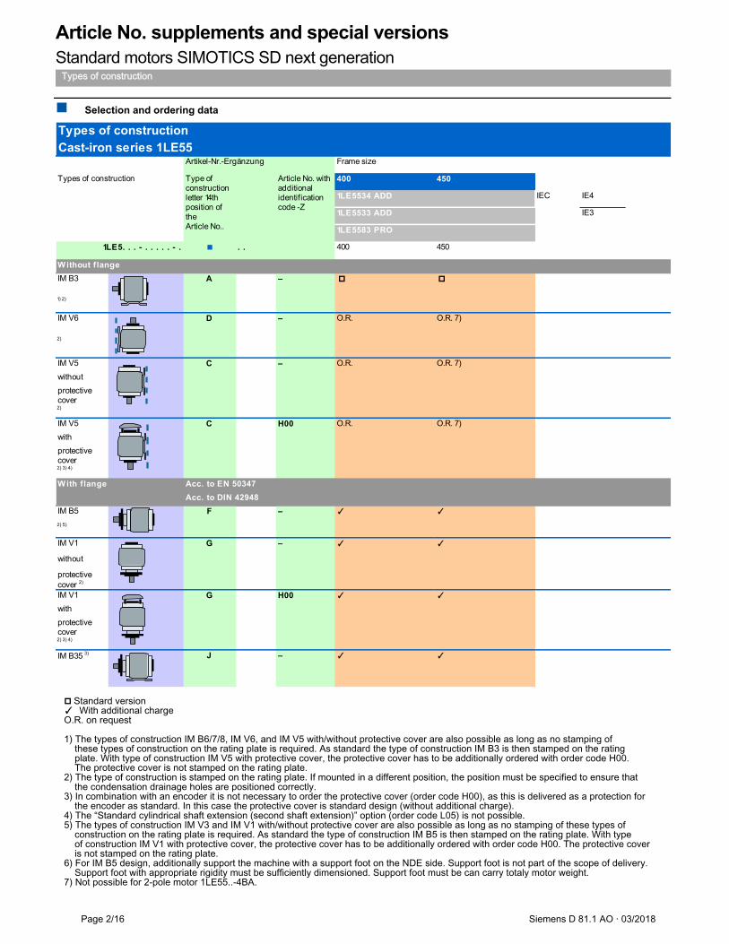
Article No. supplements and special versions Standard motors SIMOTICS SD next generation
Types of construction
Page 2/16 Siemens D 81.1 AO · 03/2018
Selection and ordering data
Standard version ✓ With additional charge O.R. on request 1) The types of construction IM B6/7/8, IM V6, and IM V5 with/without protective cover are also possible as long as no stamping of these types of construction on the rating plate is required. As standard the type of construction IM B3 is then stamped on the rating plate. With type of construction IM V5 with protective cover, the protective cover has to be additionally ordered with order code H00. The protective cover is not stamped on the rating plate. 2) The type of construction is stamped on the rating plate. If mounted in a different position, the position must be specified to ensure that the condensation drainage holes are positioned correctly. 3) In combination with an encoder it is not necessary to order the protective cover (order code H00), as this is delivered as a protection for the encoder as standard. In this case the protective cover is standard design (without additional charge). 4) The “Standard cylindrical shaft extension (second shaft extension)” option (order code L05) is not possible. 5) The types of construction IM V3 and IM V1 with/without protective cover are also possible as long as no stamping of these types of construction on the rating plate is required. As standard the type of construction IM B5 is then stamped on the rating plate. With type of construction IM V1 with protective cover, the protective cover has to be additionally ordered with order code H00. The protective cover is not stamped on the rating plate. 6) For IM B5 design, additionally support the machine with a support foot on the NDE side. Support foot is not part of the scope of delivery. Support foot with appropriate rigidity must be sufficiently dimensioned. Support foot must be can carry totaly motor weight. 7) Not possible for 2-pole motor 1LE55..-4BA.
Types of constructionCast-iron series 1LE55
Frame size
400 450
1LE5583 PRO
. . 400 450
IM B3
1) 2)
IM V6 O.R. O.R. 7)
2)
IM V5 O.R. O.R. 7)
without
protective cover2)
IM V5 O.R. O.R. 7)
with
protective cover2) 3) 4)
IM B5 ✓ ✓
2) 5)
IM V1 ✓ ✓
without
protective cover 2)
IM V1 ✓ ✓
with
protective cover2) 3) 4)
IM B35 3) J – ✓ ✓
IE41LE5534 ADD
1LE5533 ADD IE3
Artikel-Nr.-Ergänzung
Types of construction Type of construction letter 14th position of the Article No..
Article No. withadditional identification code -Z
IEC
1LE5. . . - . . . . . - .
W ithout flange
A –
–
C H00
D –
With flange Acc. to EN 50347
Acc. to DIN 42948
F
C
–
G –
G H00
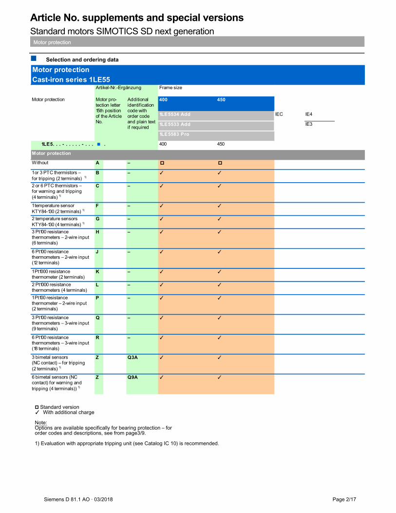
Article No. supplements and special versions Standard motors SIMOTICS SD next generation
Motor protection
Siemens D 81.1 AO · 03/2018 Page 2/17
Selection and ordering data
Standard version ✓ With additional charge Note: Options are available specifically for bearing protection – for order codes and descriptions, see from page3/9. 1) Evaluation with appropriate tripping unit (see Catalog IC 10) is recommended.
Motor protectionCast-iron series 1LE55
Frame size
Motor protection 400 450
IE3
1LE5. . . - . . . . . - . . . . 400 450
Without A –
1 or 3 PTC thermistors –for tripping (2 terminals) 1)
B – ✓ ✓
2 or 6 PTC thermistors –for warning and tripping (4 terminals) 1)
C – ✓ ✓
1 temperature sensor KTY84-130 (2 terminals) 1)
F – ✓ ✓
2 temperature sensors �KTY84-130 (4 terminals) 1)
G – ✓ ✓
3 Pt100 resistancethermometers – 2-wire input�(6 terminals)
H – ✓ ✓
6 Pt100 resistancethermometers – 2-wire input(12 terminals)
J – ✓ ✓
1 Pt1000 resistancethermometer (2 terminals)
K – ✓ ✓
2 Pt1000 resistancethermometers (4 terminals)
L – ✓ ✓
1 Pt100 resistancethermometer – 2-wire input �(2 terminals)
P – ✓ ✓
3 Pt100 resistancethermometers – 3-wire input�(9 terminals)
Q – ✓ ✓
6 Pt100 resistancethermometers – 3-wire input(18 terminals)
R – ✓ ✓
3 bimetal sensors (NC contact) – for tripping�(2 terminals) 1)
Z Q3A ✓ ✓
6 bimetal sensors (NCcontact) for warning andtripping (4 terminals)) 1)
Z Q9A ✓ ✓
Artikel-Nr.-Ergänzung
Motor pro-tection letter 15th positionof the Article No.
Additional identificationcode with order code and plain text if required
1LE5534 Add IEC IE4
1LE5533 Add
1LE5583 Pro
Motor protection
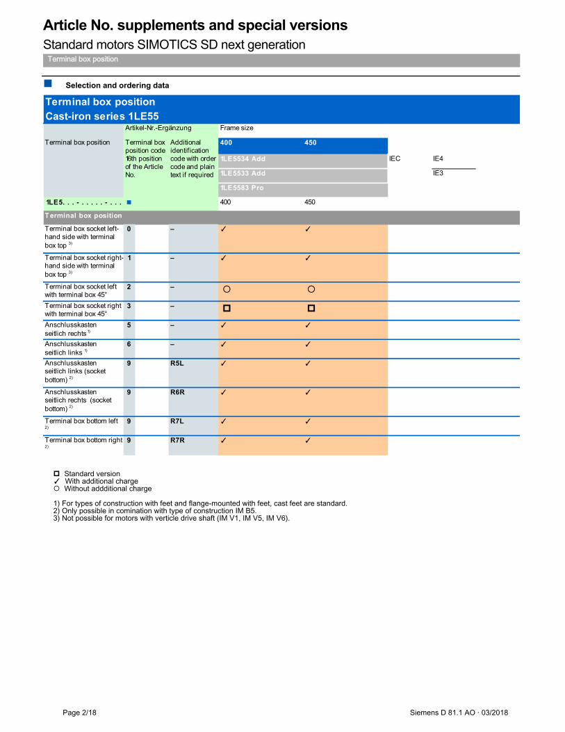
Article No. supplements and special versions Standard motors SIMOTICS SD next generation
Terminal box position
Page 2/18 Siemens D 81.1 AO · 03/2018
Selection and ordering data
Standard version ✓ With additional charge Without addditional charge 1) For types of construction with feet and flange-mounted with feet, cast feet are standard. 2) Only possible in comination with type of construction IM B5. 3) Not possible for motors with verticle drive shaft (IM V1, IM V5, IM V6).
Terminal box positionCast-iron series 1LE55
Frame size
Terminal box position 400 450
IE3
1LE5. . . - . . . . . - . . . 400 450
Terminal box socket left-hand side with terminal box top 3)
0 – ✓ ✓
Terminal box socket right-hand side with terminal box top 3)
1 – ✓ ✓
Terminal box socket left with terminal box 45°
2 –
Terminal box socket right with terminal box 45°
3 –
Anschlusskastenseitlich rechts 1)
5 – ✓ ✓
Anschlusskasten seitlich links 1)
6 – ✓ ✓
Anschlusskastenseitlich links (socket bottom) 2)
9 R5L ✓ ✓
Anschlusskasten seitlich rechts (socket bottom) 2)
9 R6R ✓ ✓
Terminal box bottom left 2)
9 R7L ✓ ✓
Terminal box bottom right 2)
9 R7R ✓ ✓
Artikel-Nr.-Ergänzung
Terminal box position code 16th position of the Article No.
Additional identification code with order code and plain text if required
T erminal box position
1LE5533 Add
1LE5583 Pro
1LE5534 Add IEC IE4
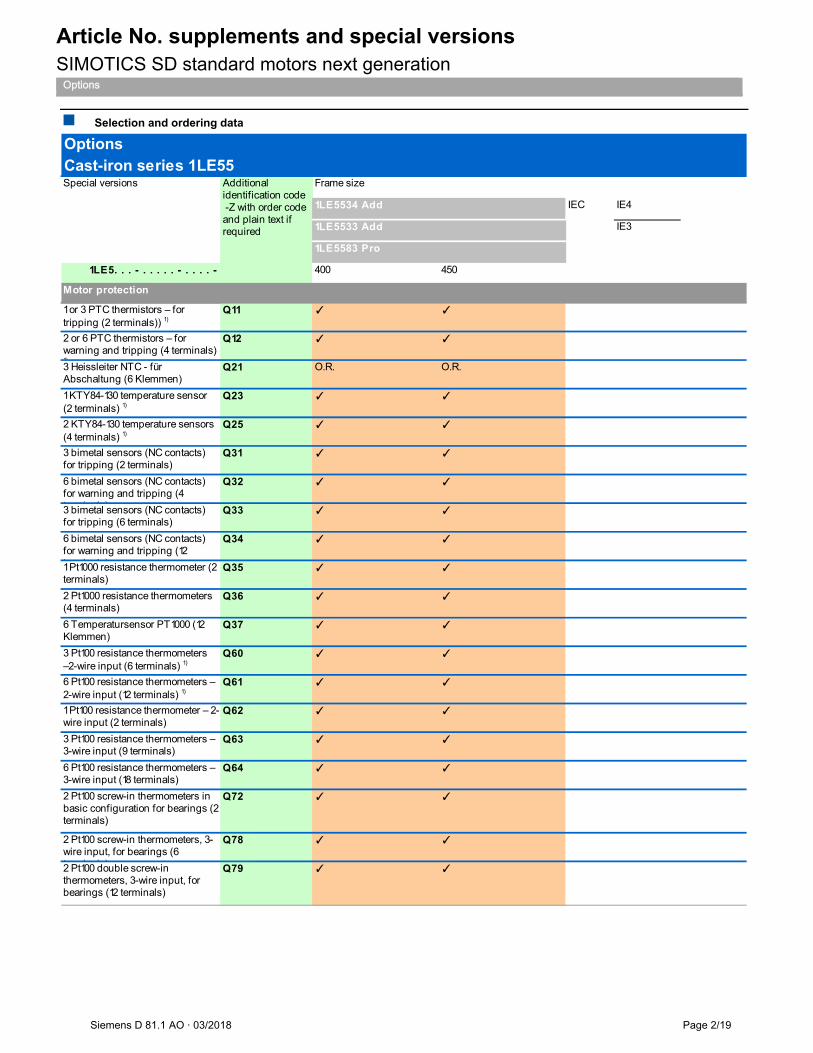
Article No. supplements and special versions SIMOTICS SD standard motors next generation
Options
Siemens D 81.1 AO · 03/2018 Page 2/19
Selection and ordering data
Special versions Frame size
IEC IE4
IE3
1LE5. . . - . . . . . - . . . . - 400 450
1 or 3 PTC thermistors – for tripping (2 terminals)) 1)
Q11 ✓ ✓
2 or 6 PTC thermistors – for warning and tripping (4 terminals) 1)
Q12 ✓ ✓
3 Heissleiter NTC - für Abschaltung (6 Klemmen)
Q21 O.R. O.R.
1 KTY84-130 temperature sensor (2 terminals) 1)
Q23 ✓ ✓
2 KTY84-130 temperature sensors (4 terminals) 1)
Q25 ✓ ✓
3 bimetal sensors (NC contacts) for tripping (2 terminals)
Q31 ✓ ✓
6 bimetal sensors (NC contacts) for warning and tripping (4 t i l )
Q32 ✓ ✓
3 bimetal sensors (NC contacts) for tripping (6 terminals)
Q33 ✓ ✓
6 bimetal sensors (NC contacts) for warning and tripping (12 t i l )
Q34 ✓ ✓
1 Pt1000 resistance thermometer (2 terminals)
Q35 ✓ ✓
2 Pt1000 resistance thermometers (4 terminals)
Q36 ✓ ✓
6 Temperatursensor PT1000 (12 Klemmen)
Q37 ✓ ✓
3 Pt100 resistance thermometers –2-wire input (6 terminals) 1)
Q60 ✓ ✓
6 Pt100 resistance thermometers – 2-wire input (12 terminals) 1)
Q61 ✓ ✓
1 Pt100 resistance thermometer – 2-wire input (2 terminals)
Q62 ✓ ✓
3 Pt100 resistance thermometers – 3-wire input (9 terminals)
Q63 ✓ ✓
6 Pt100 resistance thermometers – 3-wire input (18 terminals)
Q64 ✓ ✓
2 Pt100 screw-in thermometers in basic configuration for bearings (2 terminals)
Q72 ✓ ✓
2 Pt100 screw-in thermometers, 3-wire input, for bearings (6 t i l )
Q78 ✓ ✓
2 Pt100 double screw-in thermometers, 3-wire input, for bearings (12 terminals)
Q79 ✓ ✓
1LE5583 Pro
1LE5534 Add
1LE5533 Add
OptionsCast-iron series 1LE55
Additional identification code -Z with order code and plain text if required
Motor protection
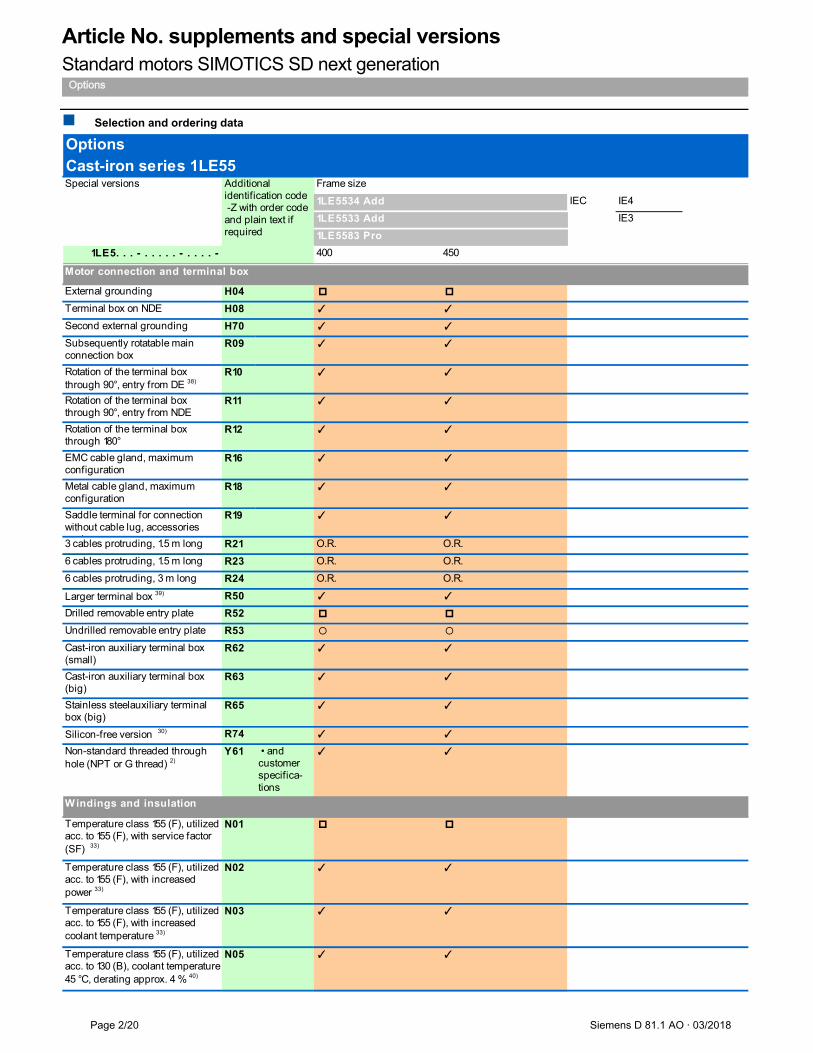
Article No. supplements and special versions Standard motors SIMOTICS SD next generation
Options
Page 2/20 Siemens D 81.1 AO · 03/2018
Selection and ordering data
Special versions Frame size
IEC IE4
IE3
1LE5. . . - . . . . . - . . . . - 400 450
1LE5583 Pro
1LE5534 Add
1LE5533 Add
OptionsCast-iron series 1LE55
Additional identification code -Z with order code and plain text if required
External grounding H04
Terminal box on NDE H08 ✓ ✓
Second external grounding H70 ✓ ✓
Subsequently rotatable main connection box
R09 ✓ ✓
Rotation of the terminal box through 90°, entry from DE 38)
R10 ✓ ✓
Rotation of the terminal box through 90°, entry from NDE
R11 ✓ ✓
Rotation of the terminal box through 180°
R12 ✓ ✓
EMC cable gland, maximum configuration
R16 ✓ ✓
Metal cable gland, maximum configuration
R18 ✓ ✓
Saddle terminal for connection without cable lug, accessories
k
R19 ✓ ✓
3 cables protruding, 1.5 m long R21 O.R. O.R.
6 cables protruding, 1.5 m long R23 O.R. O.R.
6 cables protruding, 3 m long R24 O.R. O.R.
Larger terminal box 39) R50 ✓ ✓
Drilled removable entry plate R52
Undrilled removable entry plate R53
Cast-iron auxiliary terminal box (small)
R62 ✓ ✓
Cast-iron auxiliary terminal box (big)
R63 ✓ ✓
Stainless steelauxiliary terminal box (big)
R65 ✓ ✓
Silicon-free version 30) R74 ✓ ✓
Non-standard threaded through hole (NPT or G thread) 2)
Y61 • and customerspecifica-tions
✓ ✓
Temperature class 155 (F), utilized acc. to 155 (F), with service factor (SF) 33)
N01
Temperature class 155 (F), utilized acc. to 155 (F), with increased power 33)
N02 ✓ ✓
Temperature class 155 (F), utilized acc. to 155 (F), with increased coolant temperature 33)
N03 ✓ ✓
Temperature class 155 (F), utilized acc. to 130 (B), coolant temperature 45 °C, derating approx. 4 % 40)
N05 ✓ ✓
Motor connection and terminal box
Windings and insulation
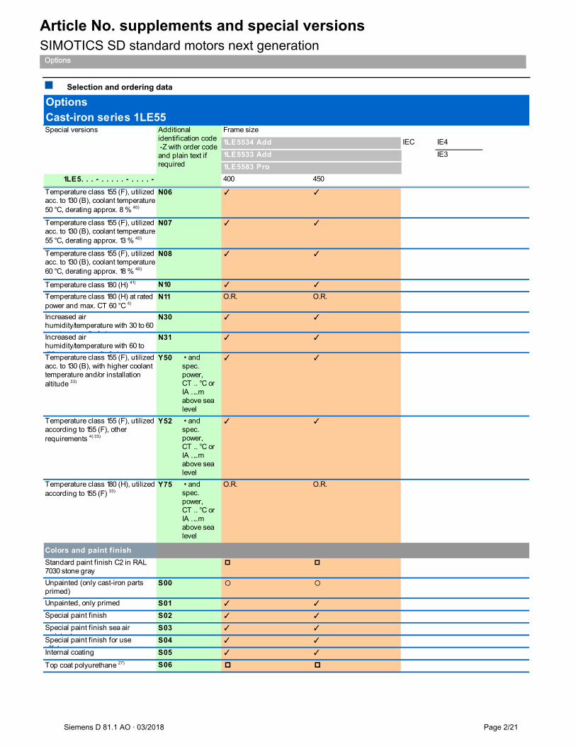
Article No. supplements and special versions SIMOTICS SD standard motors next generation
Options
Siemens D 81.1 AO · 03/2018 Page 2/21
Selection and ordering data
Special versions Frame size
IEC IE4
IE3
1LE5. . . - . . . . . - . . . . - 400 450
1LE5583 Pro
1LE5534 Add
1LE5533 Add
OptionsCast-iron series 1LE55
Additional identification code -Z with order code and plain text if required
Temperature class 155 (F), utilized acc. to 130 (B), coolant temperature 50 °C, derating approx. 8 % 40)
N06 ✓ ✓
Temperature class 155 (F), utilized acc. to 130 (B), coolant temperature 55 °C, derating approx. 13 % 40)
N07 ✓ ✓
Temperature class 155 (F), utilized acc. to 130 (B), coolant temperature 60 °C, derating approx. 18 % 40)
N08 ✓ ✓
Temperature class 180 (H) 41) N10 ✓ ✓
Temperature class 180 (H) at rated power and max. CT 60 °C 4)
N11 O.R. O.R.
Increased air humidity/temperature with 30 to 60
t 3 f i
N30 ✓ ✓
Increased air humidity/temperature with 60 to 100 t 3 f i
N31 ✓ ✓
Temperature class 155 (F), utilized acc. to 130 (B), with higher coolant temperature and/or installation altitude 33)
Y50 • andspec. power,CT .. °C orIA …. m above sealevel
✓ ✓
Temperature class 155 (F), utilized according to 155 (F), other requirements 4) 33)
Y52 • andspec. power,CT .. °C orIA …. m above sealevel
✓ ✓
Temperature class 180 (H), utilized according to 155 (F) 33)
Y75 • andspec. power,CT .. °C orIA …. m above sealevel
O.R. O.R.
Standard paint finish C2 in RAL 7030 stone gray
Unpainted (only cast-iron parts primed)
S00
Unpainted, only primed S01 ✓ ✓
Special paint finish S02 ✓ ✓
Special paint finish sea air resistant
S03 ✓ ✓
Special paint finish for use offshore
S04 ✓ ✓
Internal coating S05 ✓ ✓
Top coat polyurethane 27) S06
Colors and paint finish
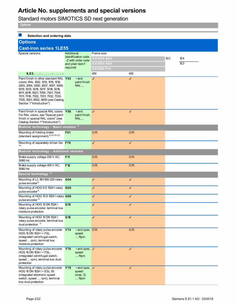
Article No. supplements and special versions Standard motors SIMOTICS SD next generation
Options
Page 2/22 Siemens D 81.1 AO · 03/2018
Selection and ordering data
Special versions Frame size
IEC IE4
IE3
1LE5. . . - . . . . . - . . . . - 400 450
1LE5583 Pro
1LE5534 Add
1LE5533 Add
OptionsCast-iron series 1LE55
Additional identification code -Z with order code and plain text if required
Paint finish in other standard RAL colors: RAL 1002, 1013, 1015, 1019, 2003, 2004, 3000, 3007, 5007, 5009, 5010, 5012, 5015, 5017, 5018, 5019, 6011, 6019, 6021, 7000, 7001, 7004, 7011, 7016, 7022, 7031, 7032, 7033, 7035, 9001, 9002, 9005 (see Catalog Section 1 "Introduction")
Y53 • and �paint finishRAL….
✓ ✓
Paint finish in special RAL colors:For RAL colors, see "Special paint finish in special RAL colors" (see Catalog Section 1 "Introduction")
Y56 • and �paint finishRAL….
✓ ✓
Mounting of holding brake (standard assignment) 6) 25) 26) 30)
F01 O.R. O.R.
Mounting of separately driven fan 34)
F70 ✓ ✓
Brake supply voltage 230 V AC, 50/60 Hz
F11 O.R. O.R.
Brake supply voltage 400 V AC, 50/60 Hz
F12 O.R. O.R.
Mounting of LL 861 900 220 rotary pulse encoder9)
G04 ✓ ✓
Mounting of HOG 9 D 1024 I rotary pulse encoder 9)
G05 ✓ ✓
Mounting of HOG 10 D 1024 I rotary pulse encoder 9)
G06 ✓ ✓
Mounting of HOG 10 DN 1024 I rotary pulse encoder, terminal box moisture protection
G15 ✓ ✓
Mounting of HOG 10 DN 1024 I rotary pulse encoder, terminal box dust protection 5)
G16 ✓ ✓
Mounting of rotary pulse encoder HOG 10 DN 1024 I + FSL (integrated centrifugal switch, speed ... rpm), terminal box moisture protection
Y74 • and spec.speed �.... Rpm
O.R. O.R.
Mounting of rotary pulse encoder HOG 10 DN 1024 I + FSL, (integrated centrifugal switch, speed ... rpm), terminal box dust protection
Y76 • and spec.speed �.... Rpm
✓ ✓
Mounting of rotary pulse encoder HOG 10 DN 1024 I + ESL 93 (integrated electronic speed switch, speed .... rpm), terminal box dust protection
Y79 • and spec.speed �(max. 3) �.... Rpm
✓ ✓
Modular technology – Basic versions 5 )
Modular technology – Additional versions
Special technology 5 )

Article No. supplements and special versions SIMOTICS SD standard motors next generation
Options
Siemens D 81.1 AO · 03/2018 Page 2/23
Selection and ordering data
Special versions Frame size
IEC IE4
IE3
1LE5. . . - . . . . . - . . . . - 400 450
1LE5583 Pro
1LE5534 Add
1LE5533 Add
OptionsCast-iron series 1LE55
Additional identification code -Z with order code and plain text if required
Low-noise version for 2-pole motors with clockwise direction of
t ti
F77
Low-noise version for 2-pole motors with counter-clockwise direction of rotation
F78
Prepared for mountings, center hole only
G40
Prepared for mountings with D16 shaft
G42 ✓ ✓
Protective cover for encoder G43 ✓ ✓
Protective cover 7) 9) 11) H00 ✓ ✓
Condensation drainage holes H03
Rust-resistant screws (externally) H07 ✓ ✓
IP65 degree of protection 13) H20 ✓ ✓
IP56 degree of protection 14) H22 ✓ ✓
Sealing ring made of fluororubber H25 ✓ ✓
Extended corrosion protection of external components
H90 ✓ ✓
Grounding brush for converteroperation 32)
L52 ✓ ✓
Coolant temperature –50 to +40 °C 15) 35)
D02 ✓ ✓
Coolant temperature –40 to +40 °C 15)
D03 ✓ ✓
Coolant temperature –30 to +40 °C 15)
D04 ✓ ✓
Electrical according to NEMA MG1-12 17)
D30
Version according to UL with "Recognition Mark" 17)
D31
Canadian regulations (CSA) 16) D40
TR CU product safety certificate EAC for Eurasian customs union
D47 ✓ ✓
Regreasing device with M10 1 grease nipple according to DIN 71412-A
L19
Located bearing DE L20
Located bearing NDE 37) L21 ✓ ✓
Bearing design for increased cantilever forces 28) 29)
L22 O.R. O.R.
Regreasing device L23
Outlet for old grease L30 O.R. O.R.
Mechanical version and degrees of protection
Coolant temperature and installation altitude
Versions in accordance with standards and specifications
Bearings and lubrication

Article No. supplements and special versions Standard motors SIMOTICS SD next generation
Options
Page 2/24 Siemens D 81.1 AO · 03/2018
Selection and ordering data
Special versions Frame size
IEC IE4
IE3
1LE5. . . - . . . . . - . . . . - 400 450
1LE5583 Pro
1LE5534 Add
1LE5533 Add
OptionsCast-iron series 1LE55
Additional identification code -Z with order code and plain text if required
Increased maximal speed L37 O.R. O.R.
Bearing insulation DE 31) 32) L50 ✓ ✓
Bearing insulation NDE 32) L51 ✓ ✓
Measuring nipple for SPM shock pulse measurement for bearing inspection
Q01 ✓ ✓
Vibration quantity level A
Vibration quantity level B 18) L00 ✓ ✓
Half-key balancing
Balancing without feather key, feather key is supplied
L01 ✓ ✓
Full-key balancing L02 ✓ ✓
Shaft extension with standard dimensions, without feather k
L04 ✓ ✓
Standard cylindrical shaft extension (second shaft end) NDE acc. to EN 50347
L05 ✓ ✓
Concentricity of shaft extension in accordance with DIN 42955 Tolerance R
L07 ✓ ✓
Concentricity of shaft extension, coaxiality, and linear movement in accordance with DIN 42955 Tolerance R for flange-mounting motors
L08 ✓ ✓
Non-standard cylindrical shaft extension, DE 19)
Y58 • and customerspecifica-tions
✓ ✓
Non-standard cylindrical shaft extension, NDE 19)
Y59 • and customerspecifica-tions
✓ ✓
Special shaft steel as requested by customer
Y60 • and customerspecifica-tions
O.R. O.R.
Sheet metal fan cover F74
Metal external fan F76 ✓ ✓
Without external fan and without fan cover
F90 ✓ ✓
Anti-condensation heating for 230 V (2 terminals)
Q02 ✓ ✓
Anti-condensation heating for 115 V (2 terminals)
Q03 ✓ ✓
Heating and ventilation
Balance and vibration quantity
Shaft and rotor
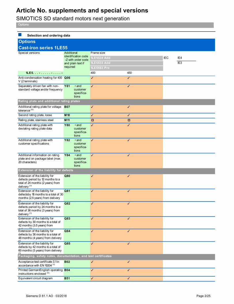
Article No. supplements and special versions SIMOTICS SD standard motors next generation
Options
Siemens D 81.1 AO · 03/2018 Page 2/25
Selection and ordering data
Special versions Frame size
IEC IE4
IE3
1LE5. . . - . . . . . - . . . . - 400 450
1LE5583 Pro
1LE5534 Add
1LE5533 Add
OptionsCast-iron series 1LE55
Additional identification code -Z with order code and plain text if required
Anti-condensation heating for 400 V (2 terminals)
Q06 ✓ ✓
Separately driven fan with non-standard voltage and/or frequency
Y81 • and customerspecifica-tions
✓ ✓
Additional rating plate for voltage tolerance 20)
B07 ✓ ✓
Second rating plate, loose M10 ✓ ✓
Rating plate, stainless steel M11
Additional rating plate with deviating rating plate data
Y80 • and customerspecifica-tions
✓ ✓
Additional rating plate with customer specifications
Y82 • and customerspecifica-tions
✓ ✓
Additional information on rating plate and on package label (max. 20 characters)
Y84 • and customerspecifica-tions
✓ ✓
Extension of the liability for defects period by 12 months to a total of 24 months (2 years) from delivery 21)
Q80 ✓ ✓
Extension of the liability for defectsby 18 months to a total of 30 months (2.5 years) from delivery 21)
Q81 ✓ ✓
Extension of the liability for defects period by 24 months to a total of 36 months (3 years) from delivery 21)
Q82 ✓ ✓
Extension of the liability for defects by 30 months to a total of 42 months (3.5 years) from delivery 21)
Q83 ✓ ✓
Extension of the liability for defects by 36 months to a total of 48 months (4 years) from delivery 21)
Q84 ✓ ✓
Extension of the liability for defects by 42 months to a total of 60 months (5 years) from delivery 21)
Q85 ✓ ✓
Acceptance test certificate 3.1 in accordance with EN 10204 21)
B02 ✓ ✓
Printed German/English operating instructions enclosed 22)
B04 ✓ ✓
Equivalent circuit diagram B51 ✓ ✓
Rating plate and additional rating plates
Extension of the liability for defects
Packaging, safety notes, documentation, and test certificates
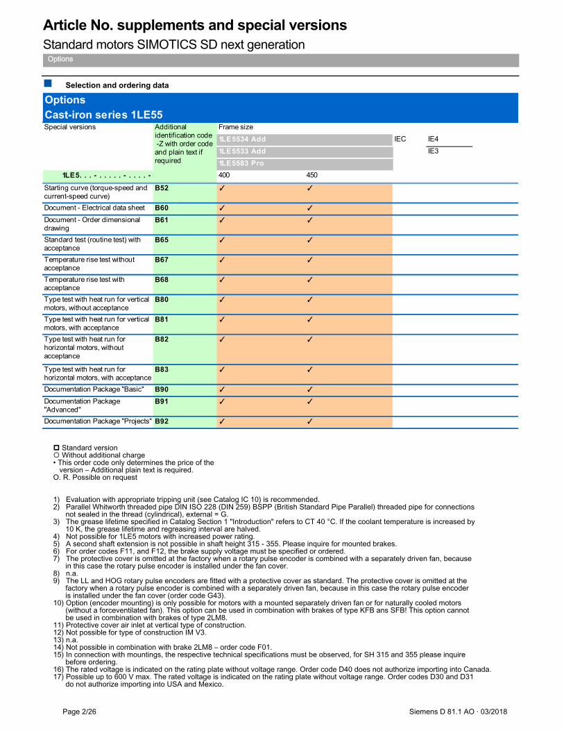
Article No. supplements and special versions Standard motors SIMOTICS SD next generation
Options
Page 2/26 Siemens D 81.1 AO · 03/2018
Selection and ordering data
Standard version Without additional charge • This order code only determines the price of the version – Additional plain text is required. O. R. Possible on request 1) Evaluation with appropriate tripping unit (see Catalog IC 10) is recommended. 2) Parallel Whitworth threaded pipe DIN ISO 228 (DIN 259) BSPP (British Standard Pipe Parallel) threaded pipe for connections not sealed in the thread (cylindrical), external = G. 3) The grease lifetime specified in Catalog Section 1 "Introduction" refers to CT 40 °C. If the coolant temperature is increased by 10 K, the grease lifetime and regreasing interval are halved. 4) Not possible for 1LE5 motors with increased power rating. 5) A second shaft extension is not possible in shaft height 315 - 355. Please inquire for mounted brakes. 6) For order codes F11, and F12, the brake supply voltage must be specified or ordered. 7) The protective cover is omitted at the factory when a rotary pulse encoder is combined with a separately driven fan, because in this case the rotary pulse encoder is installed under the fan cover. 8) n.a. 9) The LL and HOG rotary pulse encoders are fitted with a protective cover as standard. The protective cover is omitted at the factory when a rotary pulse encoder is combined with a separately driven fan, because in this case the rotary pulse encoder is installed under the fan cover (order code G43). 10) Option (encoder mounting) is only possible for motors with a mounted separately driven fan or for naturally cooled motors (without a forceventilated fan). This option can be used in combination with brakes of type KFB ans SFB! This option cannot be used in combination with brakes of type 2LM8. 11) Protective cover air inlet at vertical type of construction. 12) Not possible for type of construction IM V3. 13) n.a. 14) Not possible in combination with brake 2LM8 – order code F01. 15) In connection with mountings, the respective technical specifications must be observed, for SH 315 and 355 please inquire before ordering. 16) The rated voltage is indicated on the rating plate without voltage range. Order code D40 does not authorize importing into Canada. 17) Possible up to 600 V max. The rated voltage is indicated on the rating plate without voltage range. Order codes D30 and D31 do not authorize importing into USA and Mexico.
Special versions Frame size
IEC IE4
IE3
1LE5. . . - . . . . . - . . . . - 400 450
1LE5583 Pro
1LE5534 Add
1LE5533 Add
OptionsCast-iron series 1LE55
Additional identification code -Z with order code and plain text if required
Starting curve (torque-speed and current-speed curve)
B52 ✓ ✓
Document - Electrical data sheet B60 ✓ ✓
Document - Order dimensional drawing
B61 ✓ ✓
Standard test (routine test) with acceptance
B65 ✓ ✓
Temperature rise test without acceptance
B67 ✓ ✓
Temperature rise test with acceptance
B68 ✓ ✓
Type test with heat run for vertical motors, without acceptance
B80 ✓ ✓
Type test with heat run for vertical motors, with acceptance
B81 ✓ ✓
Type test with heat run for horizontal motors, without acceptance
B82 ✓ ✓
Type test with heat run for horizontal motors, with acceptance
B83 ✓ ✓
Documentation Package "Basic" B90 ✓ ✓
Documentation Package "Advanced"
B91 ✓ ✓
Documentation Package "Projects" B92 ✓ ✓

Article No. supplements and special versions SIMOTICS SD standard motors next generation
Options
Siemens D 81.1 AO · 03/2018 Page 2/27
Selection and ordering data
18) n.a. 19) When motors are ordered that have a longer or shorter shaft extension than normal, the required position and length of the feather keyway must be specified in a sketch. It must be ensured that only feather keys in accordance with EN 50347, Form A are used. The feather keyway is positioned centrally on the shaft extension. The length is defined by the manufacturer in accordance with the appropriate standard. Not valid for: Conical shafts, non-standard threaded journals, non-standard shaft tolerances, friction welded journals, extremely “thin” shafts, special geometry dimensions (e.g. square journals), hollow shafts. Valid for nonstandard shaft extensions DE or NDE. The feather key is always supplied. For order codes Y58, Y59, and L05 the following applies: – Dimensions D and DA ≤ inner diameter of roller bearing (see dimension tables under “Dimensions”) – Dimensions E and EA ≤ 2 × length E (normal) of the shaft extension. 20) Can be ordered for 400 VΔ/690 VY (voltage code "34"). 21) The delivery time for the factory test certificate may differ from the delivery time for the motor. 22) The Operating Instructions (compact) are available in PDF format for all official EU languages at http://support.automation.siemens.com/WW/view/en/40761976. 23) n.a. 24) Not possible in combination with order codes Q72 and Q78. 25) Not possible in combination with order codes N05, N06, N07, N08, and N11. 26) In combining order codes F01 and F12, the rectifier for the brake will be supplied separately as a single part.. 27) Order code S06 cannot be combined with order codes S00 and S01. It can be combined with Y53 on request. 28) A minimum cantilever force Fmin of 0.5·Fmax is required for NU bearings (cylindrical roller bearings) in contrast to ball bearings. Cylindrical roller bearings are not suitable for coupling output or for brief periods of no-load operation without cantilever force. 29) Admissible cantilever forces with reinforced bearings for shaft height 400 - 450 on request. Please indicate cantilever force and lever arm. 30) UL- / CSA-approval not applicable for Shaft height 400 - 450. 31) For insulated bearing DE and not insulated bearing NDE motor coupling must be insulated. 32) Grounding brush (L52) is mandatory at insulated bearing DE and NDE if there is no grounding for drive train available. Otherwise it should not be used.. 33) Only possible with motors for mains-fed operation. 34) Separately driven fan motor is carried out with voltage code 3-4 (400 V / 50 Hz; 460 V / 60 Hz). 35) Type of protection is changing to IP54 for shaft height 400 - 450. 36) Not possible for 2-pole motors and shaft height 400 - 450. 37) Not possible at vertical type of construction for shaft height 400 - 450.. 38) Only possible in combination with option H08 for motors with flange (IM B5, IM B35, IM V1). 39) Restrictions are possible when terminal box mounted. 40) Only possible in combination for SIMOTICS SD Add motors (6th position of the Article No.: 3). 41) Increased power by 5 % compared to temperature class 155 (F).
Special versions Frame size
IEC IE4
IE3
1LE5. . . - . . . . . - . . . . - 400 450
1LE5583 Pro
1LE5534 Add
1LE5533 Add
OptionsCast-iron series 1LE55
Additional identification code -Z with order code and plain text if required

Dimensions Standard motors SIMOTICS SD next generation
Cast-iron series
Page 2/28 Siemens D 81.1 AO · 03/2018
Dimension drawings
Type of construction IM B3 For flange dimension, see page 1/16 (Z = the number of retaining holes)
Type of construction IM B5 and IM V1 For flange dimension, see page 1/16 (Z = the number of retaining holes)
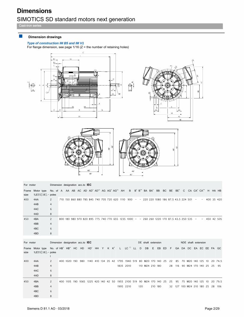
Dimensions SIMOTICS SD standard motors next generation
Cast-iron series
Siemens D 81.1 AO · 03/2018 Page 2/29
Dimension drawings
Type of construction IM B5 and IM V1 For flange dimension, see page 1/16 (Z = the number of retaining holes)
For motor Dimension designation acc.to IEC
Frame size
Motor type 1LE55[38].-
No. of poles
A AA AB AC AD AD’ AD‘‘ AG AG’ AG‘‘ AH B B’ B’’ BA BA’ BB BC BE BE’ C CA CA’ CA’’ H HA HB
400 4AA 2 710 150 860 880 785 845 740 705 720 620 1110 900 - - 220 220 1080 186 87.5 43.5 224 501 - - 400 35 420 4AB 4
4AC 6
4AD 8
450 4BA 2 800 180 980 970 820 895 775 740 770 655 1235 1000 - - 260 260 1220 170 87.5 43.5 250 535 - - 450 42 505 4BB 4
4BC 6
4BD 8 For motor Dimension designation acc.to IEC DE shaft extension NDE shaft extension
Frame size
Motor type 1LE55[38].-
No. of poles l
HB’ HB'' HC HD HD' HH Y K K’ L LC 1) LL D DB E EB ED F GA DA DC EA EC EE FA GC
400 4AA 2 400 1020 190 980 1140 410 134 35 42 1795 1940 519 80 M20 170 140 25 22 85 70 M20 140 125 10 20 74.5 4AB 4 1835 2010 110 M24 210 180 28 116 90 M24 170 140 25 25 95
4AC 6
4AD 8
450 4BA 2 400 1105 190 1065 1225 420 140 42 50 1955 2100 519 90 M24 170 140 25 25 95 75 M20 140 125 10 20 79.5
4BB 4 1995 2210 120 210 180 32 127 100 M24 210 180 25 28 106
4BC 6
4BD 8

Get more information Siemens Motors: www.siemens.com/motors Local partners worldwide: www.siemens.com/automation-contact Siemens AG Process Industries and Drives Postfach 48 48 90026 Nuernberg Germany © Siemens AG 2018 Subject to change without prior notice Printed in Germany The information provided in this catalog contains merely general descriptions or characteristics of performance which in case of actual use do not always apply as described or which may change as a result of further development of the products. An obligation to provide the respective characteristics shall only exist if expressly agreed in the terms of contract. Availability and technical specifications are subject to change without notice. All product designations may be trademarks or product names of Siemens AG or supplier companies whose use by third parties for their own purposes could violate the rights of the owners.
Security information Siemens provides products and solutions with industrial security functions that support the secure operation of plants, systems, machines and networks. In order to protect plants, systems, machines and networks against cyber threats, it is necessary to implement – and continuously maintain – a holistic, state-of-the-art industrial security concept. Siemens’ products and solutions only form one element of such a concept. Customer is responsible to prevent unauthorized access to its plants, systems, machines and networks. Systems, machines and components should only be connected to the enterprise network or the internet if and to the extent necessary and with appropriate security measures (e.g. use of firewalls and network segmentation) in place. Additionally, Siemens’ guidance on appropriate security measures should be taken into account. For more information about industrial security, please visit http://www.siemens.com/industrialsecurity. Siemens’ products and solutions undergo continuous development to make them more secure. Siemens strongly recommends to apply product updates as soon as available and to always use the latest product versions. Use of product versions that are no longer supported, and failure to apply latest updates may increase customer’s exposure to cyber threats. To stay informed about product updates, subscribe to the Siemens Industrial Security RSS Feed under http://www.siemens.com/industrialsecurity.