simple high voltage and high current meter calibration · pdf filesimple high voltage and high...
TRANSCRIPT

2560APrecision DC Calibrator
Bulletin 2560A-01EN
Simple high voltage and high current meter calibration
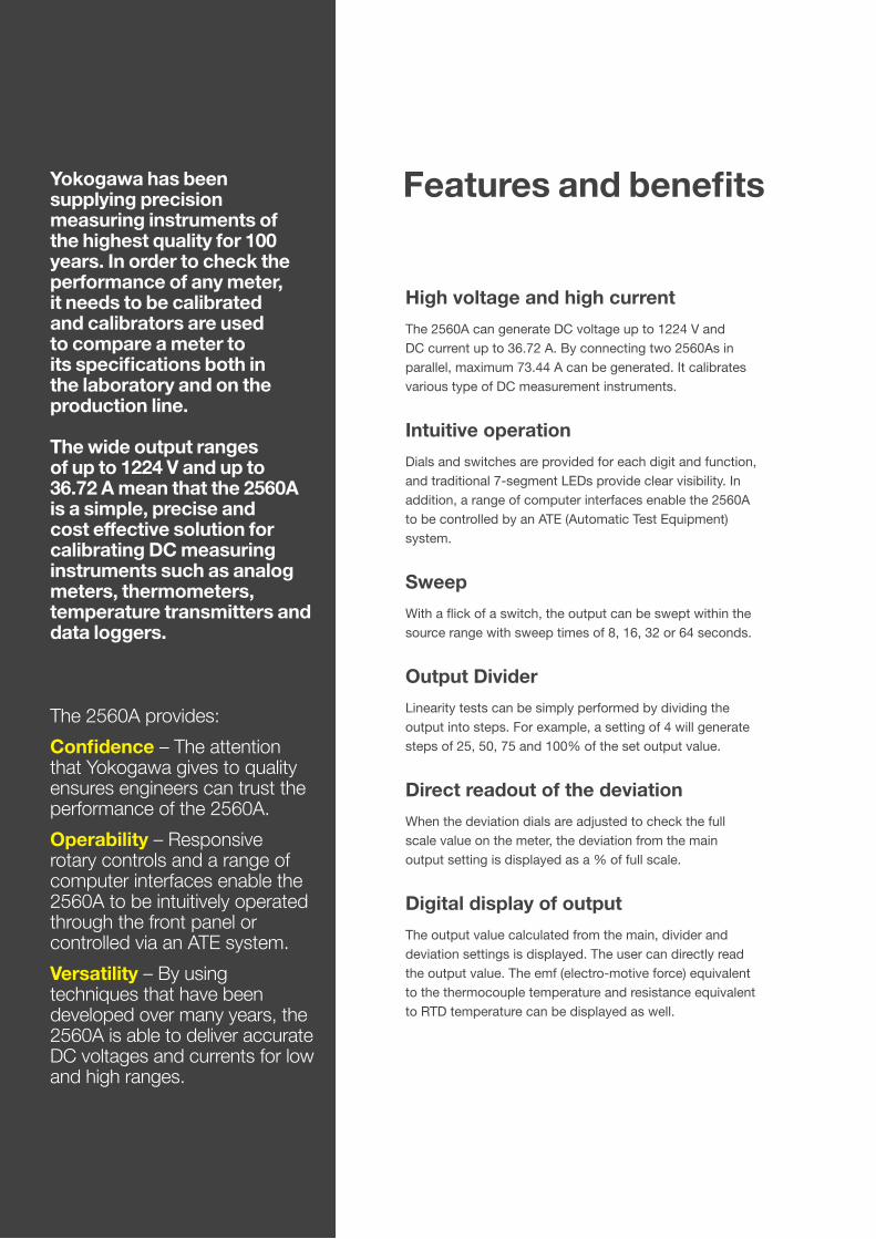
Yokogawa has been supplying precision measuring instruments of the highest quality for 100 years. In order to check the performance of any meter, it needs to be calibrated and calibrators are used to compare a meter to its specifications both in the laboratory and on the production line.
The wide output ranges of up to 1224 V and up to 36.72 A mean that the 2560A is a simple, precise and cost effective solution for calibrating DC measuring instruments such as analog meters, thermometers, temperature transmitters and data loggers.
The 2560A provides:
Confidence – The attention that Yokogawa gives to quality ensures engineers can trust the performance of the 2560A.
Operability – Responsive rotary controls and a range of computer interfaces enable the 2560A to be intuitively operated through the front panel or controlled via an ATE system.
Versatility – By using techniques that have been developed over many years, the 2560A is able to deliver accurate DC voltages and currents for low and high ranges.
Features and benefits
High voltage and high current
The 2560A can generate DC voltage up to 1224 V and DC current up to 36.72 A. By connecting two 2560As in parallel, maximum 73.44 A can be generated. It calibrates various type of DC measurement instruments.
Intuitive operation
Dials and switches are provided for each digit and function, and traditional 7-segment LEDs provide clear visibility. In addition, a range of computer interfaces enable the 2560A to be controlled by an ATE (Automatic Test Equipment) system.
Sweep
With a flick of a switch, the output can be swept within the source range with sweep times of 8, 16, 32 or 64 seconds.
Output Divider
Linearity tests can be simply performed by dividing the output into steps. For example, a setting of 4 will generate steps of 25, 50, 75 and 100% of the set output value.
Direct readout of the deviation
When the deviation dials are adjusted to check the full scale value on the meter, the deviation from the main output setting is displayed as a % of full scale.
Digital display of output
The output value calculated from the main, divider and deviation settings is displayed. The user can directly read the output value. The emf (electro-motive force) equivalent to the thermocouple temperature and resistance equivalent to RTD temperature can be displayed as well.

1 2 3
4
5 6 7
8
9
10
11
12
1 Main set value
2 Deviation
3 Output value display
4 Output terminal 1 (For 10 V range or less, 1 A range or less, binding post)
5 Temperature type selection
6 Voltage/Current range selection
7 Output divider
8 Scale setting switch
9 Sweep execution switch
10 Output ON/OFF switch
11 Output terminal 2 (Voltage) (For 100 V range or greater, safety terminal)
12 Output terminal 2 (Current) (For 10 A range or greater, binding post)
13 GP-IB Interface
14 Ethernet
15 USB Interface
16 RJ sensor connector terminal
17 Functional earth terminal
High accuracyDC voltage: ±50 ppmDC current: ±70 ppm
At 1 V and 1 mA range, for 180 days, 10 ppm = 0.001%
High stabilityDC voltage: ±10 ppm/hDC current: ±20 ppm/h
At 1 V and 1 mA range
High resolution5.5 digits, ±120000 count display6.5 digits, ±1200000 count display*
*In the high resolution mode
Wide output rangeDC voltage: −1224.00 V to +1224.00 VDC current: −12.2400 A to +36.720 A
5 voltage ranges (100 mV, 1 V, 10 V, 100 V, 1000 V)
7 current ranges (100 μA, 1 mA, 10 mA, 100 mA, 1 A, 10 A, 30 A)
The maximum output is ±122.4% of range. An instrument’s 1200 V range can be
calibrated.
14 1516
17
13
4
2560AApplications
current
current2560A
2560A Highcurrent
Close to the main scale mark
Adjust the deviation
n/m
n–1/m n+1/m
n/m
n–1/m n+1/m
From a lower value From a higher value
SWEEP HOLD SWEEP UP SWEEP HOLD
6.5 digits display example
Set MIN value
Set MAX value
Applications
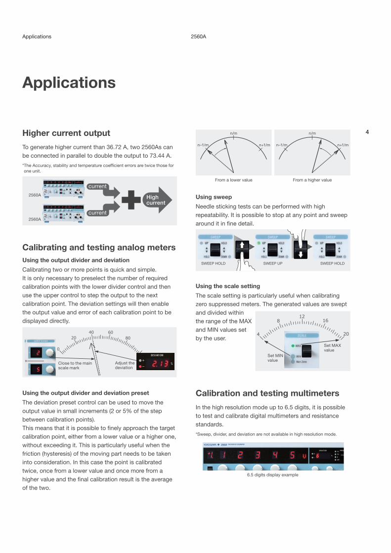
Higher current output
To generate higher current than 36.72 A, two 2560As can be connected in parallel to double the output to 73.44 A.
* The Accuracy, stability and temperature coefficient errors are twice those for one unit.
Calibrating and testing analog metersUsing the output divider and deviation
Calibrating two or more points is quick and simple.It is only necessary to preselect the number of required calibration points with the lower divider control and then use the upper control to step the output to the next calibration point. The deviation settings will then enable the output value and error of each calibration point to be displayed directly.
Using the output divider and deviation preset
The deviation preset control can be used to move the output value in small increments (2 or 5% of the step between calibration points).This means that it is possible to finely approach the target calibration point, either from a lower value or a higher one, without exceeding it. This is particularly useful when the friction (hysteresis) of the moving part needs to be taken into consideration. In this case the point is calibrated twice, once from a lower value and once more from a higher value and the final calibration result is the average of the two.
Using sweep
Needle sticking tests can be performed with high repeatability. It is possible to stop at any point and sweep around it in fine detail.
Using the scale setting
The scale setting is particularly useful when calibrating zero suppressed meters. The generated values are swept and divided within the range of the MAX and MIN values set by the user.
Calibration and testing multimeters
In the high resolution mode up to 6.5 digits, it is possible to test and calibrate digital multimeters and resistance standards.
*Sweep, divider, and deviation are not available in high resolution mode.
5
Applications/Comparison with previous models
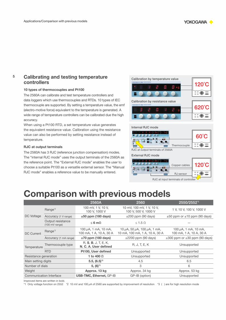
Calibrating and testing temperature controllers10 types of thermocouples and Pt100
The 2560A can calibrate and test temperature controllers and data loggers which use thermocouples and RTDs. 10 types of IEC thermocouple are supported. By setting a temperature value, the emf (electro-motive force) equivalent to the temperature is generated. A wide range of temperature controllers can be calibrated due the high accuracy. When using a Pt100 RTD, a set temperature value generates the equivalent resistance value. Calibration using the resistance value can also be performed by setting resistance instead of temperature.
RJC at output terminals
The 2560A has 3 RJC (reference junction compensation) modes. The “internal RJC mode” uses the output terminals of the 2560A as the reference point. The “External RJC mode” enables the user to choose a suitable Pt100 as a versatile external sensor. The “Manual RJC mode” enables a reference value to be manually entered.
Calibration by temperature value
RJC at output terminals of 2560A
RJC at input terminals of controller
RJ sensor
Copper cables
120˚C
620˚C
60˚C
120˚C
Calibration by resistance value
Internal RJC mode
External RJC mode
Thermocouple
Comparison with previous models2560A 2560 2550/2552*1
DC Voltage
Range*2 100 mV, 1 V, 10 V, 100 V, 1000 V
10 mV, 100 mV, 1 V, 10 V, 100 V, 500 V, 1000 V
1 V, 10 V, 100 V, 1000 V
Accuracy (1 V range) ±50 ppm (180 days) ±200 ppm (90 days) ±50 ppm or ±10 ppm (90 days)
Output resistance (100 mV range)
≤ 6 mΩ ≤ 1.5 Ω —
DC CurrentRange*2 100 μA, 1 mA, 10 mA,
100 mA, 1 A, 10 A, 30 A10 μA, 50 μA, 100 μA, 1 mA,
10 mA, 100 mA, 1 A, 10 A, 30 A100 μA, 1 mA, 10 mA,
100 mA, 1 A, 10 A, 30 A
Accuracy (1 mA range) ±70 ppm (180 days) ±2200 ppm (90 days) ±300 ppm or ±30 ppm (90 days)
TemperatureThermocouple type
R, S, B, J, T, E, K, N, C, A, User defined R, J, T, E, K Unsupported
RTD Pt100, User defined Unsupported Unsupported
Resistance generation 1 to 400 Ω Unsupported Unsupported
Main setting digits 5.5, (6.5)*3 4.5 6.5
Number of dials 5, (6)*3 3 6
Weight Approx. 13 kg Approx. 34 kg Approx. 53 kg
Communication Interface USB-TMC, Ethernet, GP-IB GP-IB (option) Unsupported
Improved items are written in bold.*1 Only voltage function on 2552 *2 10 mV and 100 µA of 2560 are supported by improvement of resolution *3 ( ) are for high resolution mode

Specifications
6
2560ASpecifications
Voltage generation
Range Source range*1 Resolution Stability (1 h)*2
±(ppm of setting + V)Accuracy (180 days)*3, 4
±(ppm of setting + V)Accuracy (1 year)*3, 4
±(ppm of setting + V)
100 mV ±122.400 mV 1 μV 20 + 3 μV 40+ 4 μV 60+ 4 μV1 V ±1.22400 V 10 μV 5 + 5 μV 40+ 10 μV 55+ 15 μV
10 V ±12.2400 V 100 μV 5 + 50 μV 40+ 100 μV 55+ 150 μV100 V ±122.400 V 1 mV 5 + 500 μV 40+ 1 mV 55+ 1.5 mV
1000 V ±1224.00 V 10 mV 5 + 5 mV *5 40+ 10 mV *5 55+ 15 mV *5
Range Temperature coefficient ±(ppm of setting + V)/˚C
Max. Output Output resistance*6
Output noise Max. C loadDC to 10 Hz 10 Hz to 10 kHz100 mV 5+ 0.3 μV 12 mA or more 6 mΩ or less 5 μVp-p 10 μVrms 10 μF
1 V 3+ 1 μV Approx.120 mA 6 mΩ or less 15 μVp-p 20 μVrms 10 μF10 V 3+ 10 μV Approx.120 mA 6 mΩ or less 50 μVp-p 30 μVrms 10 μF
100 V 3+ 100 μV Approx. 30 mA 30 mΩ or less 500 μVp-p 400 μVrms 1 μF1000 V 3+ 1 mV Approx. 10 mA 1 Ω or less 1 mVp-p 1 mVrms 0.01 μF
Current generation
Range Source range*1 Resolution Stability (1 h)*2
±(ppm of setting + A)Accuracy (180 days)*4
±(ppm of setting + A)Accuracy (1 year)*4
±(ppm of setting + A)
100 μA ±122.400 μA 1 nA 50 + 5 nA 100 + 12 nA 150 + 20 nA1 mA ±1.22400 mA 10 nA 5 + 15 nA 50 + 20 nA 70 + 30 nA
10 mA ±12.2400 mA 100 nA 5 + 150 nA 50 + 200 nA 70 + 300 nA100 mA*7 ±122.400 mA 1 μA 10 + 1.5 μA 70 + 2 μA 90 + 3 μA
1 A ±1.22400 A 10 μA 25 + 25 μA 250 + 50 μA 350 + 70 μA10 A ±12.2400 A 100 μA 50 + 500 μA 350 + 1 mA 380 + 1.2 mA30 A 0 to +36.720 A 1 mA 70 + 1.2 mA 450 + 1.5 mA 540 + 1.8 mA
Range Temperature coefficient±(ppm of setting + A)/˚C
Max. Output Output resistance
Output noise Max. L loadDC to 10 Hz 10 Hz to 10 kHz100 μA 10 + 0.5 nA Approx. 30 V 100 MΩ or more 0.1 μAp-p 0.2 μArms 1 mH
1 mA 3 + 1.5 nA Approx. 30 V 100 MΩ or more 0.5 μAp-p 0.5 μArms 1 mH10 mA 5 + 15 nA Approx. 30 V 100 MΩ or more 1 μAp-p 1 μArms 1 mH
100 mA*7 10 + 150 nA Approx. 30 V 10 MΩ or more 5 μAp-p 10 μArms 1 mH1 A 15 + 6 μA Approx. 10 V 1 MΩ or more 0.1 mAp-p 0.1 mArms 1 mH
10 A 30 + 60 μA Approx. 2 V 10 kΩ or more 1 mAp-p 4 mArms 1 mH30 A 30 + 300 μA Approx. 1.5 V 5 kΩ or more 1 mAp-p 4 mArms 1 mH
*1 To generate 122.4% of range, set main value to 120% of range and set deviation to 2%*2 1-hour stability values apply at 23˚C±1˚C. 1-hour starts from 1 hour after turning output on*3 Excluding the voltage drop by the output resistance*4 Accuracy values apply at 23±3˚C, 20% to 80%RH. Add temperature coefficient at 5˚C to 20˚C and 26˚C to 40˚C. Add 500 ppm of range when the output
value is 120% of range or greater.*5 Add {12 ppm × (output value/1000)2} of range when the output value is 100 V or greater*6 When B8506ZK, 758933, or 758917 is in use; excluding aging and the effects of measurement leads*7 Accuracy is specified when sinking the current up to 30 mA
Temperature generation for RTD
Type Source Range Resolution Accuracy(180 days)*8
Accuracy (1 year)*8 Temperature Coefficient Nominal
CurrentPt100 –200.0 to 850.0˚C 0.1˚C ±0.1˚C ±0.12˚C ±0.006˚C/ ̊C 0.1 to 2 mA
Resistance generation
Range Source Range Resolution Accuracy (180 days)*8, 9
±(ppm of setting + Ω)Accuracy (1 year)*8, 9
±(ppm of setting + Ω)Temperature Coefficient Nominal
Current400 Ω 1.00 to 400.00 Ω 0.01 Ω 55 + 0.005 75 + 0.015 ±0.002 Ω/ ̊C 0.1 to 2 mA
*8 Accuracy values apply at 23±3˚C, 20% to 80% RH. *9 Nominal current Is: In case of 0.1 mA to 1 mA, add{0.0025/Is(mA)}Ω

7
Other generation specificationSweep Target Voltage/Current/Temperature/
Resistance
Speed Approx. 8/16/32/64 sec. selectable during 0 to 100%, 100 to 0% of setting
Output divider
Target Voltage/Current/Temperature/Resistance
Denominator m 4 to 15
Numerator n 0 to 15 (n ≤ m)
Scale function
A function to set the maximum value (MAX) and minimum value (MIN) of sweep and divider range.
Deviation Target Voltage/Current/Temperature/Resistance
Variable range ±20.00%
Operation Two dials Resolution of the first dial: 0.2% of (MAX − MIN) Resolution of the second dial: 0.01% of (MAX − MIN)
Deviation preset OFF/0/2%/5%
Transient response time
Voltage/Current generation: Approx. 500 ms (except for 1000 V range), approx. 3 s (1000 V range) (No load, Time to reach 0.02% of final value)
RTD/Resistance generation: Within 0.1 ms (Time constant at changing current)
CMRR Voltage 120 dB or greater (except for 1000 V range), 100 dB or greater (1000 V range) (DC, 50/60 Hz)
Current 0.1 μA/V or less (1 A range or less), 10 μA/V or less (10 A range or more) (DC, 50/60 Hz)
General specificationWarm-up time Approx. 30 minutes
Operating environmentTemperature: 5 to 40˚C Humidity: 20 to 80% RH**20 to 70%RH for 30˚C and over
Storage environmentTemperature: –15 to 60˚C Humidity: 20 to 80% RH
Operating Height 2000 m or less
Operating Attitude Horizon
Rated power supply voltage 100 to 120 VAC/200 to 240 VAC
Allowable power supply voltage fluctuation range
90 to 132 VAC/180 to 264 VAC
Rated power supply frequency 50/60 Hz
Allowable power supply frequency fluctuation range
48 to 63 Hz
Max. power consumption 200 VA
Withstand voltageBetween power and case: 1500 VAC 1 min.
Dimensions 426 (W) × 177 (H) × 400 (D) mm
Weight Approx. 13 kg
Communication InterfaceUSB interface (PC connection)
Connector Type B connector (receptacle)
Electric and mechanical specifications
Complies with USB Rev. 2.0
supported transfer modes High Speed, Full Speed
Ethernet interface
Connector RJ-45 connector
Electric and mechanical specifications
Confirms to the IEEE 802.3
Transfer methods 100 BASE-TX/10 BASE-T
Transfer speed Max. 100 Mbps
GP-IB interface
Electric and mechanical specifications
Complies with IEEE St’d 488-1978
Functional specificationsSH1, AH1, T6, L4, SR1, RL1, PP0, DC1, DT1, C0
Address 0 to 30
Temperature generation for ThermocoupleR S B J T
Source Range [˚C] –50 to 1768 –50 to 1768 0 to 1820 –210 to 1200 –270 to 400
Setting temparature: Accuracy for 1 year (±˚C)
–50˚C: 1.10 –50˚C: 1.03 400˚C: 1.00 –210˚C: 0.25 –250˚C: 0.72 0˚C: 0.80 0˚C: 0.75 600˚C: 0.70 –100˚C: 0.11 –200˚C: 0.29 100˚C: 0.55 100˚C: 0.56 1000˚C: 0.50 0˚C: 0.08 –100˚C: 0.16 600˚C: 0.40 400˚C: 0.47 1200˚C: 0.44 1200˚C: 0.15 100˚C: 0.101600˚C: 0.40 1600˚C: 0.44 1820˚C: 0.44 400˚C: 0.091768˚C: 0.45 1768˚C: 0.51
E K N C ASource Range [˚C] –270 to 1000 –270 to 1300 –270 to 1300 0 to 2315 0 to 2500
Setting temparature: Accuracy for 1 year (±˚C)
–250˚C: 0.50 –250˚C: 0.94 –240˚C: 1.00 0˚C: 0.30 0˚C: 0.34 –200˚C: 0.20 –200˚C: 0.30 –200˚C: 0.44 200˚C: 0.26 100˚C: 0.29 –100˚C: 0.10 –100˚C: 0.15 –100˚C: 0.21 600˚C: 0.25 600˚C: 0.28 0˚C: 0.07 0˚C: 0.11 0˚C: 0.16 1000˚C: 0.30 1600˚C: 0.471000˚C: 0.12 800˚C: 0.15 800˚C: 0.15 2000˚C: 0.51 2500˚C: 0.79
1300˚C: 0.21 1300˚C: 0.20 2315˚C: 0.70
Resolution: 0.1˚COutput Resistance: Approx. 1 ΩTemperature scale is ITS-90.Accuracy apply at 23±3˚C and without reference junction compensation.Accuracy doesn’t include the thermocouple’s error.Accuracy for temperature between setting temperature is calculated by linear interpolation.Accuracy not shown in left table is ±(60 ppm + 4 µV) for generated voltage.
3 RJC modesINT*: Detect temperature of output terminal as
compensation value. Temperature measurement accuracy is ±0.3˚C.
EXT*: Detect compensation value by sensor connected to RJC terminal
MAN: Input compensation value
* When using RJC, add the reference junction compensation error in “2560A Temperature generation for Thermocouple (Detail)” on our web site.

nAny company’s names and product names mentioned in this document are trade names, trademarks or registered trademarks of their respective companies.
This is a Class A instrument based on Emission standards EN61326-1 and EN55011, and is designed for an industrial environment.Operation of this equipment in a residential area may cause radio interference, in which case users will be responsible for any interference which they cause.
Model and Suffix codeModel Suffix code Description
2560A Precision DC Calibrator
–VA Version A
–UC Deg C
–UF Deg C and F
–D UL/CSA standard, PSE compliant
–F VDE standard
–R AS standard
–Q BS standard
–H GB standard
–N NBR standard
Standard accessories :Power cord (1), B8506ZK, B8506WA (each 1), B8506ZL Alligator clip adapter set (1), 758921 Fork terminal adapter (1), Rubber feet (2 sets (4)), Terminal plug (1), User’s manual (1)
AccessoriesModel Name Description
257875 RJ sensorFor reference junction compensation sensor. Pt100, 1.95 m
B8506ZKMeasurement lead set
2 voltage output cables (red and black). 1 m. Rating 1500 V
B8506WAMeasurement lead set
2 current output cables. 1.5 m. Rating 80 A
758933Measurement lead set
2 safety terminal cables (red and black). 1 m. Rating 1000 V
758917Measurement lead set
2 safety terminal cables (red and black). 0.75 m. Rating 1000 V
B8506ZL Alligator clipadapter set
2 safety terminal—alligator clip adapters (red and black). Rating 1500 V
758929 Alligator clipadapter set
2 safety terminal—alligator clip adapters (red and black). Rating 1000 V
758922 Alligator clipadapter set
2 safety terminal—alligator clip adapters (red and black). Rating 300 V
758921 Fork terminal adapter
2 safety terminal—fork terminal adapters (red and black).
Due to the nature of this product, it is possible to touch its metal parts. Therefore, there is a risk of electric shock, so the product must be used with caution.
Rack Mounting KitsModel Product Description
751535-E4 Rack mounting kit EIA standalone installation
751535-J4 Rack mounting kit JIS standalone installation
Related product
2553A Small and light Precision DC Calibrator
Accuracy Voltage: ±0.0075%, Current: ±0.0120%
Stability ±15 ppm/h
Noise 2 µVrms
Resolution 5.5 digits, ±120000 count display
Range Voltage: ±32 V, Current: ±120 mA Thermocouple, RTD
2558A AC Voltage Current Standard
Accuracy Voltage: ±0.04% Current: ±0.05%
Stability ±50 ppm/h
Frequency range 40 to 1000 Hz
Range Voltage: 1.00 mV to 1200.0 V Current: 1.00 mA to 60.00 A
• Yokogawa’s electrical products are developed and produced in facilities that have received ISO14001 approval.
• In order to protect the global environment, Yokogawa’s electrical products are designed in accordance with Yokogawa’s Environmentally Friendy Product Design Guidelines and Product Design Assessment Criteria.
Yokogawa’s Approach to Preserving the Global Environment
External dimensions
NOTICE� Before operating the product, read the user's manual thoroughly for proper and
safe operation.
Unit: mm
3213 400426 (24.5)13
177
20