simulation of particle deposition on filter fiber in an
TRANSCRIPT
Korean J. Chem. Eng., 22(2), 303-314 (2005)
303
†To whom correspondence should be addressed.E-mail: [email protected]
Simulation of Particle Deposition on Filter Fiber in an External Electric Field
Hyun-Seol Park† and Young Ok Park
Clean Air Technology Research Center, Korea Institute of Energy Research,71-2, Jang-Dong, Yusung-Gu, Daejeon 305-343, Korea
(Received 13 September 2004 • accepted 21 December 2004)
Abstract−Particle deposition onto a filter fiber was numerically simulated when a uniform external electric fieldwas applied. The effects of electric field strength, particle inertia, and electrical conductivity of particles on particledeposition characteristics such as particle loading patterns and collection efficiency were qualitatively investigated.As a result, the electrostatic forces between a newly introduced particle and the already captured particles on the fiberwere found to have a great influence on the particle deposition patterns compared with the results where the electrostaticforces were neglected. Conductive particles and filter fibers lead to higher collection efficiency and more linear structureof particle deposits than those of dielectrics, and the particle inertia could also be more important to the collection effi-ciency of a fibrous filter when electric fields are present. The simulated particle deposits obtained from this work agreedwell with the existing experimental results, in which the photographs of particle loaded fibers, within an external electricfield, were reported.
Key words: Particle Deposition, Fibrous Filter, Electrostatic Force, External Electric Field, Simulation
INTRODUCTION
Filtration performance of a fibrous filter is directly related to theinternal structure of the filter [Park and Park, 2005; Park et al., 2001].As dust particles are captured on the filter fibers, the filter structureis changed. Consequently, the filtration characteristics are variedwith particle loading. During the initial stage of air filtration, parti-cles are first captured on clean fibers, and are subsequently depos-ited onto the already deposited particles as well as on the fibers.The deposited particles form chain-like agglomerates on the fibers,which are called dendrites [Tien et al., 1977]. Generally, it is knownthat the particle loading on a fibrous filter leads to a substantial in-crease in the collection efficiency and pressure drop [Payatakes,1976; Barot et al., 1980; Kanaoka and Hiragi, 1990; Hinds and Kadri-chu, 1997; Sakano et al., 2000]. Therefore, the structure of particledeposits on a fiber has a big effect on the performance of air filters.
The morphology and growing process of particle dendrites onthe fibers in a fibrous filter varies with the filtration conditions. Inthe presence of electrostatic forces, particles are deposited on thefilter fibers in a quite different manner compared with the cases ofno electrical forces. A few studies have been carried out on the par-ticle loading of electrically enhanced air filters. Neilsen and Hill [1980]simulated deposition patterns of charged particles onto a fiber chargedwith the opposite polarity. Baumgartner and Löffler [1987] also con-ducted a three-dimensional simulation of the deposition of polydis-perse particles on filter fibers. They showed the deposition patternsof particles having different size distributions on electrically chargedor uncharged fibers. The effect of particle loading on the perfor-mance of electrically charged fibrous filters has been experimen-tally analyzed by Walsh and Stenhouse [1998]. They proved thecharge of the collected particles had no effect on the filter degradation.
Besides the electrical charging of filter fibers, the filtration per-formance of a fibrous filter can be improved by applying an exter-nal electric field across the filter. Many theoretical and experimentalstudies have been performed over recent decades, which have ex-amined the effects of external electric fields on the collection effi-ciency of fibrous filters [Havlí ek, 1961; Zebel, 1965; Kirsch, 1971;Iinoya and Makino, 1974; Nelson et al., 1978; Kao et al., 1987; Wuet al., 1999]. However, those are for clean air filters where no par-ticles are collected.
For the studies on dust loading characteristics of air filters placedin electric fields, model filters have been used. Oak and Saville [1980]presented a number of pictures, taken with an electron microscope,of particle dendrites on an isolated fiber. In their experiments strongexternal electric fields were applied transversely to the fiber, andthe particles were weakly charged. Under those conditions, lineardendrites, protruding in the direction of electric fields, were observedin the study. Wang et al. [1980] also conducted an experimental studyon the accumulation of particles onto single fibers and the morphol-ogy of particle deposits in the presence of external electric fields,and showed the rates of particle deposition and dendrite growth forvarious external electric fields.
A theoretical analysis on the particle loading characteristics ofair filters with applied electric fields can only be accomplished byusing a numerical method, since the geometrical complexity of theparticle deposited filter consequently results in complicated electricfields within the filter. Furthermore, the morphology of the den-drites on a fiber is continuously altered as particles are collected.For this reason, it is practically impossible to exactly analyze theparticle deposition phenomena in real filters. Therefore, some approx-imations and assumptions should inevitably be used in theoreticalstudies on the particle loading of air filters enhanced by the appli-cation of an external electric field.
Auzerais et al. [1983] simulated the dendritic deposition of un-charged dielectric particles on an uncharged dielectric fiber in the
šc

304 H.-S. Park and Y. O. Park
March, 2005
presence of an electric field. They assumed that the inertia of par-ticles could be neglected for calculation simplicity, and a particledendrite was approximated to be an ellipsoid of equal volume andheight. They utilized the upper half of a fiber as a calculation domainfor reducing the computation time. As a result, the dependency ofthe structure of deposits and deposition rate of particles on the elec-tric field strength was shown.
In this study, the characteristics of particle deposition onto filterfibers in an electric field were thoroughly investigated to providemore information about the particle loading of air filters enhancedby the application of external electric fields. This was accomplishedby examining the effects of particle inertia and the electrical prop-erties of the particles and fibers on the particle deposition as well asthe effects of electric field strength and electrostatic forces betweenthe approaching particles and the previously collected particles. ALagrangian approach was adopted to simulate the particle deposi-tion. Conversely to the work of Auzerais et al. [1983], the electricalforces due to particle dendrites were calculated by the summationof the individual forces that correspond to each of the deposited par-ticles, rather than approximating a dendrite to a single assembly.This method might lead to a more accurate prediction of the par-ticle deposition. This work also provides three-dimensional viewsof the particle deposits on a fiber of finite length, which enables adirect understanding of the particle deposition phenomena.
THEORY
1. Electric Fields and Electrostatic ForcesWhen an external electric field is applied across a fibrous filter,
dust particles passing through the filter experience several types of
electrostatic forces. Assuming that all the filter fibers have no elec-trical charges, the electrostatic forces acting on a particle flowingthrough the filter are the Coulombic force due to the particle chargeand the dielectrophoretic force due to the polarization of the parti-cle. The Coulombic force is simply calculated by multiplication ofthe particle charge with the electric field strength at a given posi-tion, whereas the dielectrophoretic force is dependent on the polar-izability of the particle and the non-uniformity of the electric fields.Therefore, the electric fields and forces concerned have to initiallybe found. The electrostatic forces in fibrous filters and their effecton filtration performance have been comprehensively reviewed byShapiro et al. [1983], Brown [1993], and Wang [2001].
For a clean filter fiber, transversely placed in a uniform electricfield of strength E0, the electric field around the fiber is given withcylindrical coordinates of (r, θ, z) as follows. The coordinate sys-tem is shown in Fig. 1(a).
(1a)
(1b)
Ez=0, (1c)
where E0, Er, Eθ, and Ez denote the given external electric field strength,the radial, tangential, and z directional components of the electricfield, respectively. εf is the dielectric constant, and rf the fiber radius.Since the electric field around the fiber is axisymmetric, the z di-rectional component, Ez, is zero.
As particles are gradually captured on a fiber, the electric fieldaround the fiber changes due to deposited particles. For a more ac-curate simulation, these changes must be taken into consideration.In the present study it is assumed that the electric field around a fiberwith deposited particles can be obtained by superposition of the elec-tric fields around each of the captured particles and the electric fieldaround the clean fiber. This superposition method was used in thestudy of Auzerais et al. [1983], who proved the validity of theseapproximations.
Using the three dimensional Cartesian coordinates x, y, and z,and the spherical coordinates r', φ', and θ', as shown in Fig. 1(b),the electric field around a spherical particle placed in a homogenousexternal electric field, E0, is
(2a)
Eφ'=0, (2b)
(2c)
where Er', Eφ', and Eθ' are the radial, longitudinal, and latitudinal com-ponents of the electric field, respectively. εp is the dielectric con-stant and rp the particle radius. Here, the longitudinal component,Eφ' is zero because of the axisymmetric property of the electric fieldin the direction of the x-axis. Therefore, the resultant electric fieldaround those particles can be simply calculated as
(3a)
(3b)
Er = εf − 1εf + 1-----------rf
2
r2--- + 1
E0 θ,cos
Eθ = εf − 1εf + 1-----------rf
2
r2--- − 1
E0sinθ,
Er' = εp − 1εp + 2------------2rp
3
r'3------ + 1
E0 θ',cos
Eθ' = εp − 1εp + 2------------ rp
3
r'3----- − 1
E0sinθ',
Er' total, = Er'k= E0
εp − 1εp + 2------------2rp
3
r'k3
------ + 1 θ'k,cos
k = 1
N
∑k = 1
N
∑
Eφ' total, = Eφ'k= 0,
k = 1
N
∑
Fig. 1. Coordinate systems of (r, θ, z) and (r', φ', θ') used in thisstudy.

Simulation of Particle Deposition on Filter Fiber 305
Korean J. Chem. Eng.(Vol. 22, No. 2)
(3c)
where N is the total number of collected particles, and r'k, φ'k, and θ'k
represent the spherical coordinates whose origin is located at thecenter of the k-th deposited particle as illustrated in Fig. 2.
From Eqs. (1a)-(1c), (2a)-(2c), and (3a)-(3c), the electric fieldaround a particle loaded fiber in an external electric field in the coor-dinate system (x, y, z) is obtained as follows.
(4a)
(4b)
(4c)
One of the most important purposes of the present study is toinvestigate the effect of the electrostatic interactions between anoncoming particle and the already loaded particles on particle de-position. Therefore, the electrostatic forces due to the deposited par-ticles should be contained in the governing equation.
When a spherical particle, with some electric charge, flows pasta dust loaded filter fiber within an external electric field, it experi-ences the electrostatic forces as expressed below Eq. (5), in a vectorform. In this study, the electrostatic system of units (e.s.u.) was usedto describe the electrostatic forces.
(5)
where qp is the particle charge, rp the particle radius, εp the dielec-tric constant of particle, N the total number of deposited particles,
the electric field around a fiber, the electric field around thek-th deposited particle, and the electrostatic force.
In Eq. (5) the first term of the right hand side is the Coulombicforce due to the particle charge, and the second is the dielectropho-retic force due to the particle polarization and nonhomogeneity ofthe electric fields. According to Eq. (5), the dielectrophoretic forcemust be calculated only after obtaining the square of the magni-tude of a resultant electric field vector, which is the summation ofthe electric field around a clean fiber and the fields around each ofparticles captured on the fiber. In practice, however, it is impossible
to follow the procedure in mathematical modeling; thus an approx-imated method is adopted in this study. The approximation assumesthat the dielectrophoretic force calculated according to the aboveprocedure is equal to the sum of polarization forces between theoncoming particle and each of the captured particles, and the polar-ization force between the particle and the fiber. The validity of theapproximated calculation was proved by Auzerais et al. [1983]. Sub-sequently rearranging Eq. (5), the following equation is obtained.
(6)
Besides the forces mentioned above, the image force, due to theparticle charge, and the dielectrophoretic force, due to the polariza-tion of a fiber by the electric field around the oncoming particle,are neglected owing to their relatively small magnitudes.2. Governing Equation of Particle Motion
The first step in the simulation of particle deposition patterns ona filter fiber is the calculation of the particle trajectories. A particletrace can be obtained by solving an equation of motion of the particleconcerned. Assuming there are no Brownian diffusion effects, theequation of motion of a particle moving through a fibrous filter placedin a uniform external electric field, is written as
(7)
where m is the mass of the particle, the velocity of the particle, the drag force generated by the difference in the velocities of
fluid and the particle, the electrostatic force exerted on the par-ticle, and the gravitational force. can be expressed in severaldifferent forms, according to the value of Reynolds number (Re).Under the filtration condition of this study Re is less than 1; thusthe drag force, , is
(8)
where dp is the particle diameter, µ the kinetic viscosity of air, and are the velocities of fluid and the particle, respectively, and Cc is
the coefficient that corrects the slip effect between a particle and airmolecules. Here, Cc by Jennings [1988] was used. As a flow mod-el in a fibrous filter, the flow field suggested by Henry and Ariman[1981] was employed for this study. The flow model, where thepossibility of slip flow at the fiber surface is taken into account, ismodified from the Kuwabara flow field [Kuwabara, 1959]. The ra-dial and tangential components of the flow field are described by
(9a)
(9b)
where
J=3+2lnc−4c+c2+Kn(2+4lnc−2c2), (10a)
(10b)
(10c)
Eθ' total, = Eθ'k = E0εp − 1εp + 2------------ rp
3
r'k3
----- − 1 sinθ'k,
k = 1
N
∑k = 1
N
∑
Ex total, = Ercosθ − Eθsinθ + Er'k cosθ'k −Eθ'ksinθ'k( )
k = 1
N
∑
Ey total, = Ersinθ + Eθcosθ + Er'k sinθ'k −Eθ'kcosθ'k( )sinφk
k = 1
N
∑
Ez total, = Er'ksinθ'k −Eθ'kcosθ'k( )cosφk
k = 1
N
∑
FE = qp E + Ekk = 1
N
∑
+ rp
3
2--- εp − 1
εp + 2------------
∇ E + Ekk = 1
N
∑2
,
E Ek
FE
FE = qp E + Ekk = 1
N
∑
+ rp
3
2--- εp − 1
εp + 2------------
∇ E2
+ ∇ Ek
2
k = 1
N
∑
.
mdvdt------ = FD + FE + FG,
vFD
FE
FG FD
FD
FD = 3πµdp
Cc
-------------- u − v( ),
uv
ur = 2U0
J--------- A
rf
r---
2
+ B + Clnrrf
---
+ Drrf
---
2
cosθ,
uθ = 2U0
J--------- A
rf
r---
2
− B − C − Clnrrf
---
− 3Drrf
---
2
sinθ,
A = c2--- − 1− cKn, B = 1− c, C = − 4
12--- + Kn
, D = 12--- + Kn
c,
c = rf
b---
2
, Kn = λrf
---.
Fig. 2. A spherical coordinate system of (r'k, φ'k, θ'k), whose originis located at the center of the k-th deposited particle.

306 H.-S. Park and Y. O. Park
March, 2005
In Eqs. (10a)-(10c), c denotes the packing density of a filter, b theradius of Kuwabara cell depicted in Fig. 3, Kn the dimensionlessparameter called Knudsen number, and λ the mean free path of airmolecules.
The gravitational force, , can be expressed as
(11)
where ρp is the particle density, ρair the fluid density, and the grav-itational acceleration. Substituting Eqs. (6), (8), and (11) into Eq.(7), the following equation is obtained.
(12)
The above equation cannot be solved analytically; thus the solu-tion can be obtained only by numerical methods. For the numeri-cal calculation, Eq. (12) is divided into the three components of aCartesian coordinate system of (x, y, z), and each component equa-tion is transformed into a dimensionless form for easier manipula-tion. The final form of the governing equation is
(13a)
(13b)
(13c)
where
x*=x/rf, y*=y/rf, z*=z/rf, t*=U0t/rf, (14a)vx
*=vx/U0, vy*=vy/U0, vz
*=vz/U0, (14b)ux
*=ux/U0, uy*=uy/U0, uz
*=uz/U0, (14c)
where U0 is the undisturbed flow velocity normal to the axis of fi-ber, vx, vy, and, vz and ux, uy, and, uz are the x, y, and z componentsof particle and flow velocity, respectively.
In Eq. (13), Stk represents the Stokes number, NC is a dimen-sionless parameter describing the effect of the Coulombic force,and NP, I and NP, II denote dimensionless parameters associated withthe polarization forces due to electric fields around the fiber andthe captured particles, respectively. NREP is a dimensionless repel-lent force parameter, and NG the gravitational force parameter. Allthese dimensionless numbers represent the relative magnitudes ofthe electrostatic forces, inertial, or gravitational force to drag forceacting on an approaching particle flowing past a particle-depositedfilter fiber. Those parameters are expressed as
(15a)
(15b)
(15c)
where
. (16)
In the dimensionless governing equation F*C, r, F*
C, θ, F*C, r'k
andF*
C, θ'k are the dimensionless Coulombic forces exerted on a charged
particle along the electric field lines around the fiber, and aroundthe k-th deposited particle, respectively.
(17a)
(17b)
(17c)
(17d)
where r* and r'*k are the dimensionless radial coordinates expressedas r*=r/rf and r'*k =r'k/rf, respectively.
F*P, r, F
*P, θ, F
*P, rk
and F*P, θk
are the dimensionless dielectrophoreticforces attributed to the polarization of the approaching particle andthe nonuniformity of electric fields in the vicinity of the fiber andthe k-th deposited particle.
FG
FG = πdp
3
6-------- ρp − ρair( ) g⋅ ,
g
mdvdt------ =
3πµdp
Cc
-------------- u − v( ) + πdp
3
6-------- ρp − ρair( ) g⋅
+ qp E + Ekk = 1
N
∑
+ rp
3
2--- εp − 1
εp + 2------------
∇ E2
+ ∇ Ek
2
k = 1
N
∑
.
dvx*
dt*------- = ux
* − vx
*( ) Stk + NREP Stk⁄( ) cosθ'kk = 1
N
∑⁄
+ NC Stk⁄( ) FC r,* cosθ − FC θ,
* sinθ( )[
+ FC r'k,* cosθ'k − FC θ'
k,* sinθ'k( )
k = 1
N
∑ ,
+ NP I, Stk⁄( ) FP r,* cosθ − FP θ,
* sinθ( )
+ NP II , Stk⁄( ) FP r'k,* cosθ'k − FP θ'
k,* sinθ'k[ ]
k = 1
N
∑
dvy*
dt*------- = uy
* − vy
*( ) Stk + NREP Stk⁄( ) sinθ'ksinφ'k + NG Stk⁄
k = 1
N
∑⁄
+ NC Stk⁄( ) FC r,* sinθ + FC θ,
* cosθ( )[
+ FC r'k,* sinθ'k + FC θ'
k,* cosθ'k( )sinφ'k
k = 1
N
∑ ,
+ NP I, Stk⁄( ) FP r,* sinθ − FP θ,
* cosθ( )[
+ NP II , Stk⁄( ) FP r'k,* sinθ'k − FP θ'
k,* cosθ'k[ ] sinφ'k
k = 1
N
∑
dvz*
dt*------- = uz
* − vz
*( ) Stk + NREP Stk⁄( ) sinθ'kcosθ'kk = 1
N
∑⁄
+ NC Stk⁄( )+ FC r'k,* sinθ'k + FC θ'
k,* cosθ'k[ ] cosθ'k,
k = 1
N
∑
+ NP II, Stk⁄( )+ FP r'k,* sinφ'k − FP θ'
k,* cosθ'k[ ]cosθ'k
k = 1
N
∑
Stk = ρpdp
2U0Cc
18µrf
---------------------, NC = qpE0
3πµU0dp Cc⁄-----------------------------,
NP I, = 2αβrp
2E02 rp rf⁄( )
3πµU0dp Cc⁄---------------------------------, NP II, =
β2rp2E0
2 rp rf⁄( )4
3πµU0dp Cc⁄------------------------------,
NREP = qp
2 rf2⁄
3πµU0dp Cc⁄-----------------------------, NG =
dp2 ρp − ρair( )g18µU0 Cc⁄
-----------------------------,
α = εf − 1εf + 1-----------, β =
εp − 1εp + 2------------
FC r,*
= α 1
r*---
2
+ 1 cosθ,
FC θ,*
= α 1
r*---
2
− 1 sinθ,
FC r'k,*
= 2β rp
rf
---
3 1r'k*----
3
+ 1 cosθ'k,
FC θ'k,*
= β rp
rf
---
3 1r'k*----
3
− 1 sinθ'k,
Fig. 3. Single fiber model adopted in this study.

Simulation of Particle Deposition on Filter Fiber 307
Korean J. Chem. Eng.(Vol. 22, No. 2)
(18a)
(18b)
(18c)
(18d)
NUMERICAL SIMULATION
The filter model adopted in this study is shown in Fig. 3, whereb is the radius of the Kuwabara cell and rf is the fiber radius. Thefirst step in a simulation is to determine how to generate the par-ticles. For similarity to a real filtration, monodisperse particles aregenerated using a random process. RNUN, a random number gen-erator in IMSL routines, was used in this work. It generates a se-quence of uniform pairs (y0, z0) of pseudorandom numbers from auniform distribution between 0 and 1. y0 and z0 are the initial posi-tions of a particle in the y and z directions. Then, x0, the initial po-sition in the x direction, is calculated by x0=− As seenin Fig. 3, the dimensionless scales of the particle generation planeare 2 and 10 in the y and z direction, respectively. The sequencesof the random numbers (y0, z0) were same for each simulation inorder to make consistent comparison of the simulation results.
In this study, it is assumed that the flow velocity on the Kuwa-bara cell boundary is (U0, 0, 0) in a coordinate system of (x, y, z)depicted in Fig. 3, where U0 is the undisturbed flow velocity. There-fore, a particle starting from the particle generation plane has theinitial velocity of (U0, 0, 0). In addition, the direction of the externalelectric field of (E0, 0, 0) is also parallel to x-axis and transverse tothe fiber axis.
If the initial conditions are given, the particle trajectory can benumerically computed, using the 4-th order Runge-Kutta Method,from Eqs. (13a)-(13c). In this simulation, it was assumed that a par-ticle is captured only when the approaching particle is deposited onthe fiber surface or already deposited particles. That is, when thedistance between the center of the fiber and the approaching par-ticle is less than the sum of the particle radius and the fiber radius,and when the distance between the approaching particle and thecaptured particles is less than the particle diameter, the depositionoccurs. The calculation is terminated when either the approachingparticles reach the Kuwabara cell boundary, or the extruded parti-cle dendrites touch the cell boundary. The effects of rebound andre-entrainment of the deposited particles were not considered.
As for the electrical charge of the particles, it was assumed thatthe particles were in a Boltzmann charge equilibrium state, whichis generally accepted as the charge distribution of atmospheric aero-sol particles. The fraction of particles having n units of charge ofone sign, denoted f(n), is expressed as follows [Keefe et al., 1959].
(19)
where e is the elementary charge, n the number of elementary charge,
dp the particle diameter, k the Boltzmann constant, and T the abso-lute temperature.
The simulation conditions used in this study are summarized inTable 1. The particle size was 2 µm in diameter, so the Browniandiffusion was neglected. The sizes of the particle and fiber, the pack-ing density, the particle density, and the particle charge were fixedthroughout, as shown in Table 1, mentioned otherwise. For the con-ductive particles and fibers, the dielectric constant was assumed asinfinity, while the value was set to 4 for the dielectrics.
RESULTS AND DISCUSSION
The morphology of the particle accumulated on a filter fiber de-pends on the particle collection mechanisms of air filtration [Kanaokaet al., 1986]. Assuming no electrostatic interactions, interception,inertial impact, and Brownian diffusion are the major mechanisms.In this study, however, the electrostatic forces play a very impor-tant role in the particle deposition, whereas the Brownian diffusioneffect is small enough to be negligible, as noted before.
In the present study, the particle loading characteristics of fibrousair filters were investigated by using a Lagrangian simulation method,with a uniform external electric field applied across the filter. Spe-cifically, the effect of the electric field strength, the conductivity ofparticles and fibers, and particle inertia on the morphology of parti-cle deposits and the collection efficiency were analyzed on the basisof the simulation results. The Lagrangian simulation provides moreexact information on the effect of the filtration parameters on thefilter performance such as collection efficiency, and particle load-ing, etc. Therefore, it is expected that the morphological character-istics of the particle deposits on filter fibers in an electric field canbe largely understood from this work. 1. Effect of Electric Field Strength
Fig. 4 shows the particle deposition patterns on a cylindrical filterfiber when a uniform external electric field is applied across thefiber. The particle density was set to 1 g/cm3, and the particles andfiber were regarded as conductors. The flow direction was normalto fiber and from left to right in Fig. 4, and parallel to that of theelectric field applied. When the electric field is absent, particles arecaptured only by interception and inertial impact, and the depos-ited particles are irregularly agglomerated. For the case when anelectric field is externally applied, the particles are deposited in a
FP r,*
= − 1r*---
3
β 1r*---
2
+ cos2θ ,
FP θ,*
= − 1r*---
3
sin2θ,
FP r'k,*
= − 1r'k*-----
4
4β rp
rf
---
3 1r'k*-----
3
+ 2 cos2θ'k
− β rp
rf
---
3 1r'k*-----
3
+ 1 sin2θ'k,
FP θ'k,*
= − 1r'k*-----
4 56---β rp
rf
---
3 1r'k*-----
3
+ 1 sin2θ'k.
b rf⁄( )2 − y0
2.
f n( ) = e2
dpkTπ---------------exp
− n2e2
dpkT-------------
,
Table 1. Values of parameters used in the present study
Parameters Values
Particle diameter, dp 2 µmFiber diameter, df 10 µmUndisturbed flow velocity, U0 5, 30 cm/sPacking density of filter, c 0.05Particle density, ρp 1 g/cm3
External electric field strength, E0 5, 10, 15, 20 kV/cmParticle charge, qp Boltzmann equilibriumDielectric constant of particle, εp 4, ∞Dielectric constant of fiber, εf 4, ∞Viscosity of air, µ 1.82×10⁻⁴ PMean free path of air molecules, λ 0.065 µm

308 H.-S. Park and Y. O. Park
March, 2005
somewhat arranged pattern. As can be seen in Fig. 4(b)-4(c), thedendrites, which is the chain-like deposit of particles, become linearwith increasing electric field strength. The linear structure is due toelectrostatic forces. Fig. 5 shows the dielectrophoretic force lines inthe vicinity of a particle-loaded fiber within a uniform electric field.The direction of the electric field was from left to right, and the de-posited particles were arbitrarily positioned. The plotted force linesare those of the electrostatic force calculated by the approximatedmethod mentioned before. The external electric field polarizes thefiber and the deposited particles, and the electric forces due to thepolarization converge on the front and rear sides of the fiber andthe deposited particles. At the tip of the dendrites, especially, theattractive force lines are focused. This is why the approaching par-ticles are deposited at the end of each dendrite. In addition the di-electrophoretic force is proportional to the second power of the elec-tric field strength, E0, as expressed in Eq. (15b), thus the particle
deposits become more linear as E0 increases.Fig. 6 is a graphical representation of the number of deposited
particles with the x-axis denoting the number of generated particlesat various external electric field strengths ranging from 0 to 20 kV/cm. The other simulation conditions were the same as in Fig. 4. InFig. 6, the deposition rate, which can be defined by the gradient ofthe imaginary line for each symbol, actually represents the deposi-tion ratio, N/N0, where N is the number of deposited particles andN0 is the total number of generated particles. From Fig. 6, it can beseen that the deposition rate became higher with increasing electricfield strength, as expected. At U0=5 cm/s, the deposition rates, with10, 15, and 20 kV/cm, were almost same. On the other hand, at U0=30 cm/s, certain differences existed between them. When the flowvelocity was small, the effect of electrostatic forces on particle depo-sition became larger than in the case of high flow velocity. There-fore, at U0=5 cm/s, the collection efficiency was much higher thanat U0=30 cm/s.2. Effect of Electrostatic Forces due to Deposited Particles
Fig. 7 shows the effect of the electrostatic forces between an ap-proaching particle and the already deposited particles on the mor-phology of the particle deposits. With no electrostatic forces, an on-
Fig. 4. Particle deposits on a fiber at the externally applied uni-form electric field strength, E0, of 0 kV/cm, 10 kV/cm, and20 kV/cm, and the undisturbed flow velocity, U0, of 5 cm/s.
Fig. 5. Dielectrophoretic force lines in the vicinity of a particle-de-posited fiber within a uniform electric field.
Fig. 6. Deposition rate of particles on a fiber for various externalelectric fields at flow velocities of 5 cm/s and 30 cm/s.

Simulation of Particle Deposition on Filter Fiber 309
Korean J. Chem. Eng.(Vol. 22, No. 2)
coming particle is captured due to only the dielectrophoretic forcebetween the particles and the fiber. Therefore, the particles are packedmore densely on the fiber surface, whereas the deposits have moreporous and linear structures in the case where the electrostatic forcesdue to the collected particles are considered. The numbers of de-posited particles plotted in Fig. 7 are 100 for both cases. The othersimulation conditions are the same as used in Fig. 4.
Using the data of Fig. 7, the particle deposition rates are shownin Fig. 8. As can be seen, the particles are collected on the fiber atalmost the same deposition rate, regardless of the electrostatic inter-actions between the oncoming particles and deposited particles. FromFig. 7 and Fig. 8, it is concluded that the deposition pattern of par-ticles on a fiber within an external electric field is greatly influencedby the deposited particles on the fiber, even though the particle de-position rate is constant, irrespective of the electrostatic forces dueto particle deposits. In general, the filtration performance of a fibrousfilter, such as pressure drop or dust holding capacity, is highly de-pendent on the structure of the particle deposits. Therefore, the elec-trostatic forces due to the already deposited particles must be includedin the calculation of the particle trajectories.3. Effect of Electrical Conductivity of Particles and Filter Fi-bers
So far, the particles and fibers have been considered as perfectconductors, whose dielectric constants are infinity. This assumptionwas based on the comments of other researchers. Kraemer and John-stone [1955] reported that the resistivities usually encountered ininsulators are not large enough to prevent the entire surface of theparticles from becoming an equipotential surface in an extremelyshort time; thus the particle should behave as a conductor. Kirsch[1972] also mentioned in his study using a model filter consistingof capron fibers that in view of the presence of easily ionized im-purities and contamination on the fiber surface the dielectric con-stant of the fiber can be assumed as infinity. Most of the previous
theoretical studies on electrically enhanced air filtration, however,have treated dielectric filters and particles as pure dielectrics withtheir own constants. From those approaches, the real filtration phe-nomena such as dust loading characteristics can’not be fully under-stood.
In this section, the effects of the dielectric constants of particlesand filter fibers on the structures of particle deposits are analyzed.Especially, the linear structure of the particle dendrites was observedin the experimental studies of Oak and Saville [1980], with an exter-nal electric field applied across an isolated fiber.
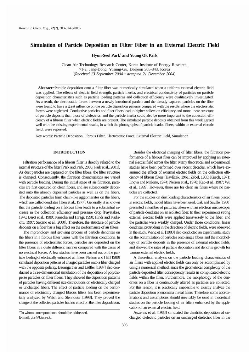
Fig. 9 compares the particle deposition patterns for conductivefibers and particles with those for dielectrics. The dielectric constantsof particles and fibers were assumed to be equal, and set to infinityand 4 for the conductors and dielectrics, respectively. The other var-iables were fixed as U0=5 cm/s, E0=15 kV/cm, and ρp=1 g/cm3. Inthe case of the conductors, the particles tended to build up linear den-drites leading to porous structures. On the other hand, the dielectricparticles were deposited in a somewhat irregular pattern, formingless porous deposits. Furthermore, all the conductive particles released
Fig. 7. Particle deposition patterns simulated with and without theelectrostatic forces between an approaching particle andthe already deposited particles on a fiber at E0=10 kV/cmand U0=5 cm/s: (a) With electrostatic forces due to depos-ited particles, (b) Without electrostatic forces due to depos-ited particles.
Fig. 8. Deposition rate of particles as a result of simulation calcu-lated with and without the electrostatic forces between anapproaching particle and the already deposited particleson a fiber at external electric fields of 5 kV/cm and 10 kV/cm.
310 H.-S. Park and Y. O. Park
March, 2005
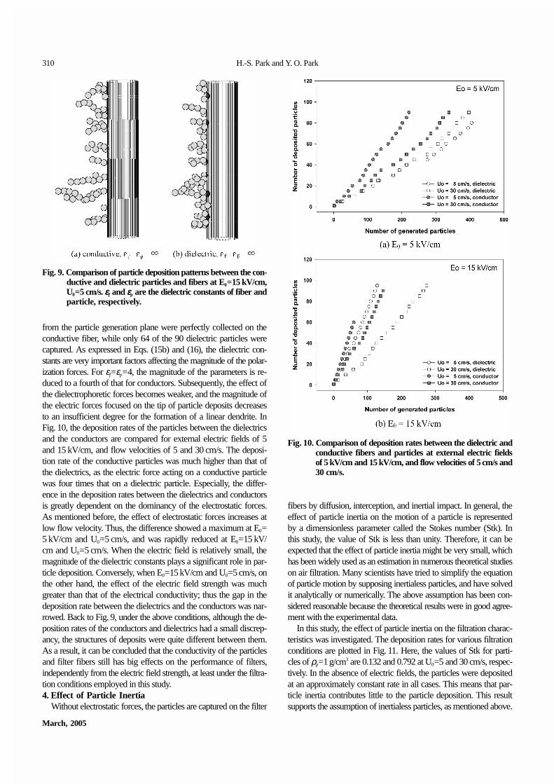
from the particle generation plane were perfectly collected on theconductive fiber, while only 64 of the 90 dielectric particles werecaptured. As expressed in Eqs. (15b) and (16), the dielectric con-stants are very important factors affecting the magnitude of the polar-ization forces. For εf=εp=4, the magnitude of the parameters is re-duced to a fourth of that for conductors. Subsequently, the effect ofthe dielectrophoretic forces becomes weaker, and the magnitude ofthe electric forces focused on the tip of particle deposits decreasesto an insufficient degree for the formation of a linear dendrite. InFig. 10, the deposition rates of the particles between the dielectricsand the conductors are compared for external electric fields of 5and 15 kV/cm, and flow velocities of 5 and 30 cm/s. The deposi-tion rate of the conductive particles was much higher than that ofthe dielectrics, as the electric force acting on a conductive particlewas four times that on a dielectric particle. Especially, the differ-ence in the deposition rates between the dielectrics and conductorsis greatly dependent on the dominancy of the electrostatic forces.As mentioned before, the effect of electrostatic forces increases atlow flow velocity. Thus, the difference showed a maximum at E0=5 kV/cm and U0=5 cm/s, and was rapidly reduced at E0=15 kV/cm and U0=5 cm/s. When the electric field is relatively small, themagnitude of the dielectric constants plays a significant role in par-ticle deposition. Conversely, when E0=15 kV/cm and U0=5 cm/s, onthe other hand, the effect of the electric field strength was muchgreater than that of the electrical conductivity; thus the gap in thedeposition rate between the dielectrics and the conductors was nar-rowed. Back to Fig. 9, under the above conditions, although the de-position rates of the conductors and dielectrics had a small discrep-ancy, the structures of deposits were quite different between them.As a result, it can be concluded that the conductivity of the particlesand filter fibers still has big effects on the performance of filters,independently from the electric field strength, at least under the filtra-tion conditions employed in this study.4. Effect of Particle Inertia
Without electrostatic forces, the particles are captured on the filter
fibers by diffusion, interception, and inertial impact. In general, theeffect of particle inertia on the motion of a particle is representedby a dimensionless parameter called the Stokes number (Stk). Inthis study, the value of Stk is less than unity. Therefore, it can beexpected that the effect of particle inertia might be very small, whichhas been widely used as an estimation in numerous theoretical studieson air filtration. Many scientists have tried to simplify the equationof particle motion by supposing inertialess particles, and have solvedit analytically or numerically. The above assumption has been con-sidered reasonable because the theoretical results were in good agree-ment with the experimental data.
In this study, the effect of particle inertia on the filtration charac-teristics was investigated. The deposition rates for various filtrationconditions are plotted in Fig. 11. Here, the values of Stk for parti-cles of ρp=1 g/cm3 are 0.132 and 0.792 at U0=5 and 30 cm/s, respec-tively. In the absence of electric fields, the particles were depositedat an approximately constant rate in all cases. This means that par-ticle inertia contributes little to the particle deposition. This resultsupports the assumption of inertialess particles, as mentioned above.
Fig. 9. Comparison of particle deposition patterns between the con-ductive and dielectric particles and fibers at E0=15 kV/cm,U0=5 cm/s. εf and εp are the dielectric constants of fiber andparticle, respectively.
Fig. 10. Comparison of deposition rates between the dielectric andconductive fibers and particles at external electric fieldsof 5 kV/cm and 15 kV/cm, and flow velocities of 5 cm/s and30 cm/s.

Simulation of Particle Deposition on Filter Fiber 311
Korean J. Chem. Eng.(Vol. 22, No. 2)
In the case where the electric field of 5 kV/cm was applied, thegraph shows different features from those when E0=0 kV/cm. AtU0=30 cm/s, the deposition rate of the particles of ρp=1 g/cm3 washigher than that when they were to be inertialess. This means that
under a specific filtration condition, even the particles of ρp=1 g/cm3 can have a great effect on the particle deposition. The differ-ence in the deposition rates between inertia and inertialess particlesbecomes very small at E0=15 kV/cm, as seen in Fig. 11(c), wherethe electrostatic forces are much more dominant than particle iner-tia. As a result, it can be stated that the assumption neglecting theparticle inertia can introduce an error when predicting the filtrationperformance, especially in theoretical studies on the particle load-ing characteristics of electrically enhanced air filters.5. Comparison with Existing Studies
In the present study, the effect of the external electric fields onparticle deposition on a fiber was investigated by using a numeri-cal simulation. Auzerais et al. [1983] conducted a similar simula-tion study to ours. Their study was confined to the low velocity casesso that the particle inertia could be neglected, and the dielectric con-stants of the particles and fibers were fixed as 4. Fig. 12 shows thedeposition rates of the particles for this study and those of Auzeraiset al. [1983]. Auzerais et al. [1983] assumed inertialess particlesand εp=εf=4, while in the present study the particle density was 1 g/cm3 and εp=εf=∞. Flow velocity in both studies was 5 cm/s, andthe other conditions were the same as those described in Table 1.In all cases of E0, the deposition rates in this study were much greaterthan those of Auzerais et al. [1983]. This might be largely attrib-uted to the difference in the conductivity of the particles and fibersbetween the two studies. As previously mentioned in Fig. 10, theeffect of the electrical conductivity was remarkable at low flow veloc-ities.
Another reason for the difference is likely to come from the cal-culation method for the electrostatic forces between a new particleand already captured particles. Auzerais et al. [1983] treated a den-drite as an ellipsoid, with equal volume and height, and calculatedthe electrostatic forces between the oncoming particle and the ellip-soid. On the other hand, in the present study, the forces betweenthe newly generated particle and each of captured particles werecomputed individually. The latter method is more tedious and time-consuming, but more accurate than the former.
This study provides a qualitative insight to the particle depositioncharacteristics of fibrous filters, using a numerical simulation method,
Fig. 11. Effect of particle inertia on the particle deposition rate atexternal electric fields of 0 kV/cm, 5 kV/cm, and 15 kV/cm, and flow velocities of 5 cm/s and 30 cm/s.
Fig. 12. Comparison of deposition rates in this study with those ofAuzerais et al. [1983] for various electric field strengths atU0=5 cm/s.

312 H.-S. Park and Y. O. Park
March, 2005
with an applied homogeneous external electric field. The simulationresults are in very good agreement with the existing experimentaldata, such as Kraemer and Johnstone [1955], Havlicek [1961], Kir-sch [1972], Iinoya and Makino [1974], Nelson et al. [1978], Oakand Saville [1980], Wang and Ho [1980], and Oak et al. [1985] interms of the qualitative aspects. Especially, the linear dendritic struc-ture of the particle deposits, as photographed by Oak and Saville[1980], was exactly simulated in this work.
CONCLUSIONS
This paper addressed the particle deposition characteristics of fi-brous air filters enhanced by an external electric field. Using a Lag-rangian simulation method, the trajectories of particles were calcu-lated, and the deposition structures obtained. The effects of the elec-tric field strength, electrostatic forces due to the captured particles,the electrical conductivity of the particles and fibers, and particleinertia on the morphology of the deposits and the deposition rate ofparticles were investigated.
As the electric field intensity increased, the collection efficiencybecame higher, and particles were deposited in a linear dendriticform. The linear structure of the particle deposits resulted in the fo-cusing of electrostatic force lines on the tip of particle dendrites.The electrostatic forces due to the deposited particles had a greatinfluence on the particle deposition pattern, although the effect ofthe forces on the deposition rate was very small. Therefore, the elec-trostatic interaction between the approaching particles and thosepreviously captured must be taken into account in theoretical stud-ies on the dust loading of electrically enhanced air filters. The mor-phology of the simulated particle deposits was in good agreementwith the others’ experimental results.
The electrical conductivity of the particles and filter fibers had aconsiderable effect on the particle deposition. The conductive parti-cles built up linear dendrites leading to porous structures, while thedielectric particles were deposited in a more irregular and denseform. The deposition rate of the conductive particles was much higherthan that of the dielectrics. From this study it was also found thatthe particle inertia, which has been assumed to be negligible in nu-merous previous studies on air filtration, could influence the collec-tion efficiency of air filters, with an applied uniform electric field.The particles of only 1 g/cm3 were collected with a higher efficiencythan the inertialess particles under specific filtration conditions.
The results of this study agreed very well with those of the pre-vious experimental studies in terms of the qualitative aspects. Spe-cifically, compared with the study of Auzerais et al. [1983], this workpredicted much higher collection efficiencies. This was mainly dueto the difference in the electrical conductivity of the particles andthe filter fibers between the two studies. In the present study, theparticles and filter fibers were regarded as perfect conductors, whichhave been considered to reflect the real filtration phenomena moreaccurately. Finally, this study is expected to be helpful in under-standing filtration properties of electrically enhanced air filters, espe-cially the dust loading of air filters within an external electric field.
ACKNOWLEDGMENT
This research was performed with the financial support of the
Center for Nanostructured Materials Technology under the 21st Cen-tury Frontier R&D Program of the Ministry of Science and Tech-nology, Korea.
NOMENCLATURE
A : constant, see Eq. (10b)b : radius of Kuwabara cellB : constant, see Eq. (10b)c : packing density of a filterC : constant, see Eq. (10b)Cc : Cunningham correction factorD : constant, see Eq. (10b)dp : particle diametere : elementary chargeE : electric field strength
: electric fieldE0 : uniform electric field strength
: electric field around the k-th deposited particleEr : radial component of electric field Eθ : tangential component of electric field Ez : z-directional component of electric field Er' : radial component of electric field in spherical coordinate
system shown in Fig. 1Eφ' : longitudinal component of electric field in spherical coor-
dinate system shown in Fig. 1Eθ' : latitudinal component of electric field in spherical coordi-
nate system shown in Fig. 1f(n) : fraction of particles having n units of charge of one sign, see
Eq. (19): drag force: electrostatic force: gravitational force
F*C, r : radial component of dimensionless Columbic force between
the approaching particle and fiberF*
C, θ : tangential component of dimensionless Columbic force be-tween the approaching particle and fiber
F*C, r'k
: radial component of dimensionless Columbic force betweenthe approaching particle and k-th deposited particle
F*C, θ'k
: latitudinal component of dimensionless Columbic force be-tween the approaching particle and k-th deposited particle
F*P, r : radial component of dimensionless dielectrophoretic force
between the approaching particle and fiberF*
P, θ : tangential component of dimensionless dielectrophoreticforce between the approaching particle and fiber
F*P, rk
: radial component of dimensionless dielectrophoretic forcebetween the approaching particle and k-th deposited par-ticle
F*P, θk
: latitudinal component of dimensionless dielectrophoretic forcebetween the approaching particle and k-th deposited particle
: gravitational accelerationJ : constant, see Eq. (10a)k : Boltzmann constantKn : Knudsen numberm : mass of particlen : number of elementary chargeN : total number of deposited particles
E
Ek
FD
FE
FG
g

Simulation of Particle Deposition on Filter Fiber 313
Korean J. Chem. Eng.(Vol. 22, No. 2)
NC : dimensionless parameter, see Eq. (15a)NP, I : dimensionless parameter, see Eq. (15b)NP, II : dimensionless parameter, see Eq. (15b)NREP : dimensionless parameter, see Eq. (15c)NG : dimensionless parameter, see Eq. (15c)qp : particle charge r* : dimensionless radial coordinate in the cylindrical coordi-
nate systemr'*
k : dimensionless radial coordinate in the spherical coordinatesystem whose origin is located at the center of the k-th de-posited particle
rf : fiber radiusrp : particle radiusRe : Reynolds numberStk : Stokes number, see Eq. (15a)t : timeT : absolute temperature
: fluid velocityU0 : magnitude of undisturbed flow velocity
: particle velocity (ux, uy, uz) : x, y, z components of fluid velocity(u*
x, u*y, u
*z) : dimensionless x, y, z components of fluid velocity
(vx, vy, vz) : x, y, z components of particle velocity(v*
x, v*y, v
*z) : dimensionless x, y, z components of particle velocity
(x, y, z) : rectangular coordinates(x*, y*, z*) : dimensionless rectangular coordinates(x0, y0, z0) : initial position of a particle (r, q, z) : cylindrical coordinates in Fig. 1(r', φ', θ') : spherical coordinates in Fig. 1(r'k, φ'
k, θ'k) : spherical coordinates whose origin is located at the
center of the k-th deposited particle as illustrated in Fig. 2
Greek Lettersα : constant, see Eq. (16)β : constant, see Eq. (16)εf : dielectric constant of fiberεp : dielectric constant of particleλ : mean free path of air moleculesµ : kinetic viscosity of airρair : air densityρp : particle density
REFERENCES
Auzerais, F., Payatakes, A. C. and Okuyama, K., “Dendritic Depositionof Uncharged Aerosol Particles on an Uncharged Fiber in the Pres-ence of an Electrical Field,” Chemical Engineering Science, 38(3),447 (1983).
Bai, H., Lu, C. and Chang, C. L., “A Model to Predict the System Per-formance of an Electrostatic Precipitator for Collecting PolydisperseParticles,” J. of the Air & Waste Management Assoc., 45, 908 (1995).
Barot, D. T., Tien, C. and Wang, C., “Accumulation of Solid Particleson Single Fibers Exposed to Aerosol Flows,” AIChE J., 26(2), 289(1980).
Baumgartner, H. and Löffler, F., “Three-Dimensional Numerical Simu-lation of the Deposition of Polydisperse Aerosol Particles on FilterFibres Extended Concept and Preliminary Results,” J. Aerosol Sci-
ence, 18(6), 885 (1987).Havlí ek, V., “The Improvement of Efficiency of Fibrous Dielectric
Filters by Application of an External Electric Field,” Int. J. Air andWater Poll., 4, 225 (1961).
Henry, F. and Ariman, T., “Cell Model of Aerosol Collection by FibrousFilters in an Electrostatic Field,” J. Aerosol Science, 12(2), 91 (1981).
Hinds, W. C. and Kadrichu, N. P., “The Effect of Dust Loading on Pen-etration and Resistance of Glass Fiber Filters,” Aerosol Science andTechnology, 27, 162 (1997).
Iinoya, K. and Makino, K., “Application of Electric Field Effects to DustCollection Filters,” Aerosol Science, 5, 357 (1974).
Jennings, S. G., “The Mean Free Path in Air,” J. Aerosol Science, 19(2),159 (1988).
Kanaoka, C. and Hiragi, S., “Pressure Drop of Air Filter with Dust Load,”J. Aerosol Science, 21(1), 127 (1990).
Kanaoka, C., Emi, H., Hiragi, S. and Myojo, J., Morphology of Particu-late Agglomerates on a Cylindrical Fiber and a Collection Efficiencyof a Dust Loaded Fiber, 2nd Int. Aerosol Conf., 674 (1986).
Kao, J., Tardos, G. I. and Pfeffer, R., “Dust Deposition in Electrostati-cally Enhanced Fibrous Filters,” IEEE Transactions on Industry Ap-plications, IA-23(3), 464 (1987).
Keefe, D., Nolan, P. J. and Rich, T. A., “Charge Equilibrium in AerosolsAccording to the Boltzmann Law,” Proceedings of the Royal IrishAcademy, 60, 27 (1959).
Kraemer, H. F. and Johnstone, H. F., “Collection of Aerosol Particles inPresence of Electrostatic Fields,” Industrial and Engineering Chem-istry, 47(12), 2426 (1955).
Kuwabara, S., “The Forces Experienced by Randomly Distributed Par-allel Circular Cylinders or Spheres in a Viscous Flow at Small Rey-nolds Numbers,” J. of the Physical Society of Japan, 14(4), 527(1959).
Nelson, G. O., Bergman, W., Miller, H. H. and Taylor, R. D., “Enhance-ment of Air Filtration Using Electric Fields,” Am. Ind. Hyg. Assoc.J., 39, 472 (1978).
Nielsen, K. A. and Hill, J. C., “Particle Chain Formation in Aerosol Fil-tration with Electrical Forces,” AIChE J., 26(4), 678 (1980).
Oak, M. J. and Saville, D. A., “The Buildup of Dendrite Structures onFibers in the Presence of Strong Electrostatic Fields,” J. of Colloidand Interface Science, 76(1), 259 (1980).
Park, H.-S. and Park, Y. O., “Filtration Properties of Electrospun UltrafineFiber Webs,” Korean J. Chem. Eng., 22(1), 165 (2005).
Park, Y. O., Park H.-S., Park, S. J., Kim, S. D., Choi, H. K. and Lim,J. H., “Development and Evaluation of Multilayer Air Filter Media,”Korean J. Chem. Eng., 18(6), 1020 (2001).
Payatakes, A. C., “Model of Aerosol Particle Deposition in Fibrous Me-dia with Dendrite-Like Pattern. Application to Pure Interception dur-ing Period of Unhindered Growth,” Filtration & Separation, 602(1976).
Sakano, T., Otani, Y., Namiki, N. and Emi, H., “Particle Collection ofMedium Performance Air Filters Consisting of Binary Fibers underDust Loaded Conditions,” Separation and Purification Technology,19, 145 (2000).
Shapiro, M., Laufer, G. and Gutfinger, C., “Electric forces in AerosolFiltration in Fibrous and Granular Filters A Parametric Study,” Atmo-spheric Environment, 17(3), 477 (1983).
Tien, C., Wang, C. and Barot, D. T., “Chainlike Formation of ParticleDeposits in Fluid-Particle Separation,” Science, 196, 983 (1977).
u
v
šc

314 H.-S. Park and Y. O. Park
March, 2005
Walsh, D. C. and Stenhouse, J. I. T., “Parameters Affecting the LoadingBehavior and Degradation of Electrically Active Filter Materials,”Aerosol Science and Technology, 29, 419 (1998).
Wang, C., “Electrostatic Forces in Fibrous Filters a Review,” PowderTechnology,” 118, 166 (2001).
Wang, C. S., Ho, C. P., Makino, H. and Iinoya, K., “Effect of Electro-static Fields on Accumulation of Solid Particles on Single Cylinders,”
AIChE J., 26(4), 680 (1980).Wu, Z., Walters, J. K. and Thomas, D. W. P., “The Deposition of Parti-
cles from an Air Flow on a Single Cylindrical Fiber in a UniformElectrical Field,” Aerosol Science and Technology, 30, 62 (1999).
Zebel, G., “Deposition of Aerosol Flowing Past a Cylindrical Fiber in aUniform Electric Field,” J. of Colloid Science, 20, 522 (1965).