(sin-’a wing m@ of attack in steady flight, radians (w/’t
TRANSCRIPT
REPORT 925
I
STABILITY DERIVATIVES AT SUPERSONIC SPEEDSOF THIN RECTANGULAR l~TGS WITH DIAGONALS AHEAD OF TIP MACH LINES
By SIDNEY M. HAEMON
SUMMARY
Theoretical results are obtained, by mean8 oj the linearized
theq, for the w~ace-celotity-potet itil functions, wrface-
premme di8&ibutiotw, and tibility deriratiw for rariuus
rnotion8 at 8uper80nic 8peed8 of thin $at rectangular m“ng8
m“thout dihedral. T7M inre8tigatian includes steady and accel-
erated rertical and longitudinal motion-s and steady rolling,
yawing, side81ip~”ng, and pitching for Jfach mm berg and
aapect mt iog greater than those for which tie Mach line from
the leading edge of the tip 8ection intersects the tmiling edge
of the opposite tip 8ectian. The 8tability deriratire8 are dem.ced
ol~”th regpe~ to princi~l body ai-eg and then tmwsf ormed to a
8y8te7n of 8tabi[ity axe8. In the ca8eof yawing, a treatmentJorthe infinitely long wing which tah-e8account of the spanwi8e
rariation in the 8tream Mach number is extended to the jnitewing, and a p[aum.bieralthough not rigorous, 8olution ti obtainedfor the wing tip e$ects.
The result8 jor this inre8tigation 8how<dthat potitire yawingat 8uper80nic speeds may produce a negatire rolling momentin contra8t to the behavior at 8ub80nia8peed8where a po8itirerolling moment would be produced. The attainment of super-sonic 8peed 8hou[d produce a signl~cati change in the pom.tice
direction of the yawing moment per unit rolling relocity. The
rewlts a180 indicate that urwtable tendencie8 are produced by
rertiiwl accekrationa if
M’+1.4 @?–= > --ij--
where A is wing a8pect mtio and M b stream Mach number.
INTRODUCTION
Recent dem40pments in supersonic airfod theory (refer-ences 1 to 4) have Ied to the calculation of many of thesupersonic stabihty derivatives for various pkn forms. Inreferences 5 to 8, various theoretical supersonic stabilityderivatives for small disturbances are presented for thin flatwings of delta plan form. In reference 9, the supersonicdamping due to rollkg is given for triangular, trapezoidal,and related pIan forms.
In the present paper the methods of references 4, 10, and1I, which are based on the linearized theory for a uniformstream Mach number, are used to derive the supersonicsurface-veIocity-po tential functions for thin flat rectangularwings -without dihedral in steady and accekrated verticalmotions and steady roMng, sidedipping, and pitchingmotions. The potential functions that are obtained are then
used to derive formulas for the pressure distributions and thestability derivatives for the foregoing motions and ak forsteady yawing. In the case of yawing, a simpIe treatmentgiven in reference 7 for the in6niteIy long wing, which takesaccount of the spanwise variation in stream Mach numberassociated with yawing, has shown that the ~umption of auniform Mach number is far from adeqrmte to describe thecompressibility effects. This treatment is e~tended hereinin order to evahmte the w~~ tip effects for the yawing tit e-span wing.
The steady motions that are treated herein are assumedto give small deviations from the undisturbed flight pathand the accelerated motions are assumed to ha-re smrdIaccelerations. Theoretical results based on this assumptionfor steady motiops have, in general, been found to be reliable;however, the reliability of such reauks for unsteady motionsis as yet unvded. The resuhs presented herein cover arange of Mach number and aspect ratio greater than thatfor which the Mach Ike from the Ieading edge of the tipsection intersects the traihrg edge of the opposite tip section.
l!,y%,1’0
1
U,P,W
tiwvv’
pm
aMB= ~~
P
Ci
d
SYMBOLS
rectangular coordinates (see fig. 1)induced flow velocities aIong x- and y-axes,
respectivelycoordinate in flight direction if this direction
is inclined to x-asisincremental flight ~elocities along x-, y-, and
z-axes, respectively (see fig. 2)deri-rative of u with respect to timeaccelerated verticaI motionundisturbed ilight velocitylocaI @ght velocity after disturbance; used to
indicate inclination of flight direction toz-axis (see ~. 1)
angular velocities about z-, y-, and z-axes,re.spectiveIy (see fig. 2)
speed of soundstream Mach number (’t”/a)
( -’aMach angle sin
wing m@ of attack in steady flight, radians(w/’t-)
IocaI inclination of airfoiI surface with respect
()to free stream, radians *U
101
https://ntrs.nasa.gov/search.jsp?R=19930091990 2020-06-17T03:23:22+00:00Z
REPORT 92 5—NATIONAL
derivative of a with respect to timetime following disturbance, secondsangle of sideslip, radians (v/V)chordwing Semispmwing spantotal wiw area
ADVISORY COMMI’M7EE FOB AERONAUTICS
region of- integration over portion of wingsurface (see.fig. 3)
distance of o~gin of stability axes from themidchord point, measured along x-axis,positive ahead of midchord point
mass density of airdisturbance-velocity potentiaI on upper sur-
face of airfoilauxiliary variabks which replace x and y, re-
spectively (see fig. 1)indicates a transformation of origin of x- and
y-axes or & and ~-axes from leading edge ofcenter section to leading edge of tip section(y.=y–h on right half-wing; V==–y–hon Ieft half-wing)
pressure dfierence between lower and uppersurfaces of airfoil, positive in direction oflift
nondimensional coefficient expressing ratio ofpressure difference between lower andupper surfaces of airfoil to free-stream
AP
()dynamic pressure —; V2
constant given by equation (9)induced suction force on wing tip per unit
Iength of tipforces paraIIelto z-, y-, and z-axes, respectively
(see fig. 2)x
()longitudinal-force coefficient ——
; V2S
Y“
()lateral-force coefficient —; Vzs
z
()vertical-force coefficient —$ ~72s
skin-friction drag coefficient
(Skin-frickm dra
$ V2S‘)
moments about z-j g-j and z-axes, respec-tively (see fig. 2); M is also used to refer toMach number
●
cm()rolling moment coefficient —Z–-
; ~?s~~
M
()
pitching-moment coefficient .-$ j7%&
Nyawing-moment coefficient
()
_-— .....; ~72sb
Subscript:1,2 contributions of normal pressures and skin
friction, respcctivcly, to C.,; also used Loindicate component parts of CiB,CZ&, Cm&tC.u, and C%
Superscript:WP contributions cauacd by vertical motion and
roIIing motion, respectivelyWhenever p, q, r, f?, a, u, b, and u aro used as subscripts,
a nondimensional derivative is indicated and this derivativeis the slope through zero. For example:
Unprimed stability derivatives refer to principaI lx-xl-yams; pr_@ecl stability derivative refer to stabiIity axes.
ANALYSIS
GENERAL CONCEPTS
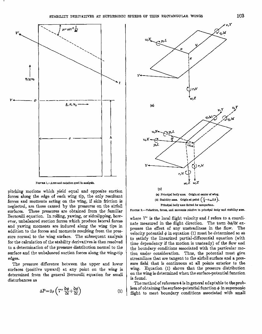
The coordinate axes and tho symbols used in tlw analysisof the rectangular wing are shown in figuro 1. TIN dcrivatimof the formulas for the surface-veIocit.y-pokntial functions,pressure distributions, and stability derivatives is madeinitisIIy with reference to principal body a.scswhich nro fixedin the wing with the origin at the midchord of the ccutcr
section();,0,0,This system of mes is shown in figure 2 (a),
The transformation of these stability derivatives to a syskmof stabili~y axes (fig. 2 (b)) is discussed in t.hosection entitled‘TksuIt.s and Discussion.”
The stability derivatives are determined from integrationsof the forces and moments over the wing. For vertical and
STAIUIJFY DERNAT13’ESAT SUPERSONIC SPEEDS OF THIN RECICANGULARWINGS 103
v’
\
/%Y,%
v— 0 —-—-————— -——. Ih%%-
C 1 h
—
Fmmw L–hes andmtatfonm-sin ar@is&.
pitching motions -rrbich yieId equaI and opposite suctionforces along the edge of each wing tip, the only resultantforces and moments acting on the wing, if skin friction isnegIected, are those caused by the pr=ures on the airfoilsurfaces. These pressures are obtained from the familiarBernoulli equation. In rolling, yawing, or sidedipping, ho-+v-mwr, unbalanced suction forces which produce lateral forcesand yawing moments me induced aIong the wing tips inaddition to the forces and moments resulting from the pres-sure normal to the ming surface. The subsequent analysisfor the calculation of the stability derivatives is then resolvedto a determination of the pressure distribution normaI to thesurface and the unbalanced suction forces along the wing-tipedges.
The pressure difference between the upper and lowersurfaces (positive upward) at any point on the wing isdetermined from the genersl Bernoulli equation for smfldisturbances as
(1)
/ Z?,Y
[d
-QK’r,NT’I;
W,z W*2
(bl
(@ Prblcipnfhdy mea. Ortgblat carlkf of Wfog.
(b) StabLIityaxes. Origfnatpint (:–%0,0).
Prlnct@ body axesdotted faremqwhn.
FIGUIW2.—Vdmitfe% forces,and mome-atiralatka to prb.whmfbody and stab~y a=.
where V’ is the Iocal flight velocity and ? refers to a coordi-nate measured in the @ht direction. The term Zhi@t ex-presses the effect of any unsteadiness in the fhw. Thevelocity potential @ in equation (1) must be determined so asto satisfy the Linearized partialdifferential equation (withtime dependency if the motion is unsteady) of the flow andthe boundary conditions associated with the particular mo-tion under consideration. Thus, the potential must givestreamlines that are tangent to the airfoil surface and a pres-sure field that is continuous at aII points exterior to thewing. Equation (1) shows that the pressure distributionon the wing is determined when the surface-potential functionis found.
The method of reference4 isin general adaptabIe to theprcblem of obtaining the surface-potential function @ in supemonicflight to meet boundary conditions a=ociated ~th sma~

104 REPORT 92 5—NATIONAL ADVISORY COMMITTEE FOR AERONAUTICS
steady motions, such as vertical motions, rolling, sideslipping,and pitching. The method is an extension, to include tip ef-fects, of the work of Puckett and others which usw the super-position of elementary source solutions to obtain the potentialfunction. In cases where a point on the wing is influencedby two or more mutually interacting external fields; the inter-action introduces dif%culties in the solution for the surfacepotential. (See also reference 12.) If any point on the wingis influenced by only one independent external field, however,the potentiaI function in a region affected by the wing tipmay be obtained by integration of elementary source solu-tions solely over an appropriate area of the wing. Thestrength of these sources is shown to be a function only of thelocal slope of the airfoil surface with reference to the free-stream direction. Inasmuch as the slope of the airfoil sur-face with reference to the.free-stream direction is known for agiven motion, the distribution of sources is known and, con-sequently, the distribution of the surface-pot.ential functionis determined by an integration of the elementary sourcesolutions over an appropriate area of the wing.
As applied to the rectangular wing at supersonic speeds,the foregoing method of reference 4 for. one independentexternal field is valid as long as the foremost Mach wavefrom one tip does not intersect the opposite tip, that is, forMach numbers and aspect ratios for which A.B> 1. Forthis case, the potential at a point on the top surface of athin flat wing may be determined by means of equation (14)of reference 4 and is as foIIows:
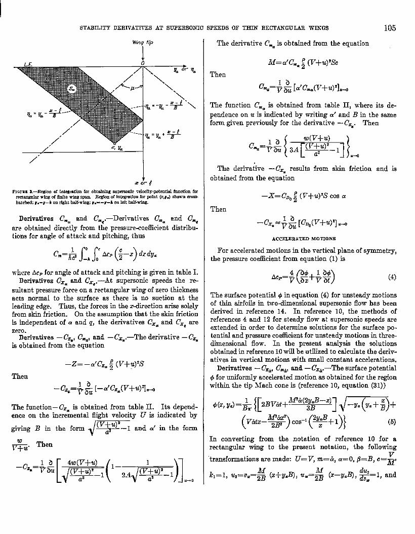
where a’ represents the local angle of attack of the airfoilsurface at the point (t,qa). Figure 3 shows a typical region& for determining the potential at a point (x,vJ in arectanguhir wing. The figure shows the boundaries & overwhich the integration must he performed, for a point (X,ya)which is affected by the wing-tip region. If the point(x,ya) is located at or inboard of the foremost Mach linefrom the tip, this point is unaffected by the tip region andSw is bounded by the leading edge and the Mach foreconefrom (z,yJ, Suppose that the surface potential @(z,y) hasbeen obtained from equation (2) or by some other method,then the dHerentiation of @ with respect to the coordinatein the free-stream direction determines the pressure distri-bution by means of the Berriiulli relation, equation (l).
The e.xpresaionsfor determining the surface potential andthe pressure coe5cient for unsteady motions are discussedin the section entitled ‘(Derivation of Formulas.”
DERIVATION OF FORMULAS
The subsequent derivation of formulas for the variousmotions will involve first the determination of distributionsof surface potential and then the determination of surface-preasure diet.ributions and any unbalanced suction forces
along the wing tips. The integrals required for thsc dcriva-tiom and also those required for tho stability dcrivativos arcintegrabh either directly or after reduction by pwts by mmnsof standard formulas such as arc given in rcferencc ]3;hence, the detaik for the intcgrat.ions am noL shown.In the operations involving factoring from radicals, ccu+rmust be used to pm.serve tho correct sign of the fack)~si forexample, if
Ya<othen
@=4(–Ya)’=–%
For brevity, the find formulas am omit,tmlfrom the deriva-tions and appear only in tables at the end of tho paprr.Thus, the distributions of @ ad AcP arc summrwizcd intable I, and the stability derivative mo sumrnmizcd intable II.
All the derivations arc made specifically for n wing forw~~ch .M3> 2, that is, for which the forcmos L Jhwh wwvcfrom a tip cloes not intersect tho rcmoto half-wing. Theformulas in table I for the potential # and prwsure cocfikicn~ACPthat are obtained for JIB>2 can ho appIied to wings inwhich 1 ~ All ~.2 by using thu principh? of symmetry andsupcrpming separately each tip effect at the point. underconsideration to the vahm obtained for tho infinitely longwing. ._Aconsideration of this superposition principle for [lLC
rectangular wing shows, howwer, that tho stability &x+ra-tives which are obtained for AB>2 apply as well tu wingsfor which A.B21. A more det.aiIeddescription of t.able 11is given in the section entit~ed “RMults and Discussion.”
V l?RTICAh PITCHING, AND LONGITUI)INAL MOTIONS
Derivatives – Cz=and – Cza,—I?or stutidypituhing motionabout a lateral atis through the midchonl poinL-,fllc locnlslope of the airfoil surface with rcspccL to the frco-strmmdirection is
()+a’=a+—~..-q
where a is the angle of attack in the tibscnco of pitching.In order to obtain the potential distribution, this wduc ofa’ is substituted into equation (2) and tho doublo integrationfor the variables g and q. is pcwformcd bctwccn the limilsindicated in figure 3. The prossure cocflicicnt is then ob-tained from equation (1) for steady motions as
(3)
These pressurecoefficients arc then diffcrc.ntiatmlwith respectto a and q. The integrations of the respective disLributiousof ACP over the wing and conversion to nondimensionalunits then give the derivativea —Czaand —C’S,.
STARILITY DERJS’ATIYES AT SUPERSONIC SPEEDS OF THIN RECTA3WULAR WINGS
Wing tip
I4’
, % u=t
/’-
FIGrEEs.—Regiou d Ir@mtion for obtddng m-c docity-potential fnndion forremodor WIU IXJ3nItewfnum Re#on of Imemtion h POht (ZJJ Shm CMShatched r.=f–k on rightMf-wiu H.-–pi on M half-wing.
Derivatives C== and CmC,—Derivatives Cm= and Cacare obtained directly from the pressure-coefficient distribu-tions for angle of attack and pitching, thus
C.=bs:hl’c’(i-’)’r”.where AcPfor angle of attack and pitching is given in table 1.
Derivatives CX=and ~=c,—At supersonic speeds the re-suhant pressure force on a rectangulex wing of zero thidcnessacts nornd to the surface as there is no suction at theleading edge. Thus, the forces in the redirection arise solelyfrom skin friction. On the assumption that the skin frictionis independent of a and q, the derivatives Cx= and C’xnarezero.
Derivatives —CzU,C%, and —C~~.—The derivative —C’ZUis obtained from the equation
–Z= –a’Cz= ~ (V+ U)2LS
Then
1 b [–a’cz=(v+@7H– cz==~ ~
The function– C?z=is obtained from table II. Its depend-ence on the incremental flight velocity U is indicated by
/(V+U)2
giving B in the form ~ ~f —I and a’ in the form
i%b”‘hen
–Cz==+;.W(’-’-’d(+)ltio’)lti
The derivative C.a is obtained from the
M=a’cua ; (V+ U)?!YC
Then
105
equation
c%=+& [a’cm=(~+@qM
The function C== is obtained from table H, where its de-pendence on u is indicated by writing c-e’and B in the sameform ghen pretiously for the derivative —C’z=. Then
c.=+&{3A[-Ju.The deri~a~ive —Cxu results from .&in friction and is
obtained from the equation
—x= CDO;(V+u)wCos Ci
Then
‘~X==+& [~Do(v+u)2] u+
ACCELERATED .MOTIONS
For accelerated motions in tha vertical p~aneof symmetry,the pressure coefhcient from equation (1) is
‘.=x%+%’) (4)
The surface potential @in equation (4) for unsteady motionsof thin airfoils in two-dimensional supersonic flovr has beenderived in reference 14. In reference 10, the methods ofreferences 4 and 12 for steady flow at supersonic speeds areextended in order to determine solutions for the surface po-tential and pressure coticient for unsteady motions in three-dimensional flow. In the present anaIysis the solutionsobtained in reference 10will be utilized to cakulate the deriv-atives in vertical motions with small constant accelerations.
Derivatives – Cz&,C=&,and – CX&.—The surface potential@ for uniforndy accelerated motion as obtained for the regionwithin the tip Mach cone is (reference 10, equation (31))
In converting from the notation of reference 10 for a
rectemguhm wing to the prwent notation, the following
“transformations are made: C7=V, m=ti, a=O, 19=B, c=~I
h=l, u~=o.=~ (z+ IY.B), u.=% (z–Y.B), *=1, and
106 REPORT 92 5—NATIONAL ADVISORY COl@lI~EE FOR AERONAUTICS
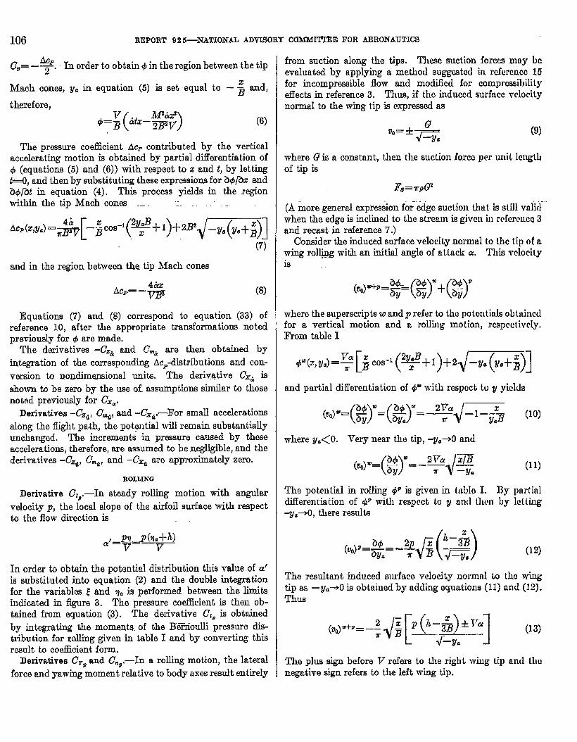
C,= –~. In order to obtain 4 in the region between the tip.
Mach cones, VCin equation (5) is set equal to – ~ and,
therefore,
(6)
The pressure coefhient AcF contributed by the verticalaccelerating motion is obtained by partial diilerentiation ofd (equations (5) and (6)) with respect to x and t, by lettingt=o, and then by substituting these expressionsfor ZM@Xand&f@ in equation (4). This process yields in the regionwithin the tip Mach cones .. —.
(7)
and in the region between tha tip Mach cones
‘Cp=–$% (8)
Equations (7) and (8) correspond to equation (33) ofreference 10, after the appropriate transformations notedpreviously for 4 aro made.
The derivatives –C,& and CmUare then obtained byintegration of the corresponding Acp-distributions and con-version to nondimensional units. The derivative Cxti is
ahown to be zero by the use of assumptions simihtr to thosenoted previously for Gka.
Derivatives –CZti, (7%, and –CXfit-For small accelerationsalong the flight path, the potgntial will remain substantiallyunchanged, The increments in pressure caused by theseaccelerations, therefore, are assumed to be negligible, and thederivative –G-a, C~ti,and -Cxti are approximately zero.
ROLLING
Derivative CIP.—In steady rolling motion with anguIarvelocity p, the local S1OPGof the airfoil surface with respectb the flow direction is
In order to obtain the potential distribution this vahe of a’is substituted into equation (2) and the double integrationfor the variables .&’and qa is performed between the limitsindicated in figure 3. Tho pressure coefficient is then ob-tained from equation (3). The derivative C?lPis obtainedby integrating the moments. of the IRErioulli pressure dis-tribution for rolling given in table I and by converting thisresult to coe5cient form.
Derivatives C~Pand C,P,-In a rolling motion, the lateralforce and yawing moment relative to body axes result entirely
from suction along the tips. These suction forws may beevaluated by applying a method suggmtcd in rcfcrencc 15for incompressible flow and modified for coxnprcssibilityeffects in reference 3. Thus, if the induced surface velocitynorrmd to the wing tip is expressed as
“=+ (9)
where Q is a constant, then the suetion force pw unit.Icngtbof tip is
F8=uPP
(A more general expression fo;”~go suction Lbatis still vafirlwhen the edge is inclined to the stream is given in rcfcm.wcc3and recast in reference 7.)
Consider the induced surface velocity normal to the tip of awing roll@g with an initial angle of attaclc a. This velocityia
where the superscriptsw and p refer to the POtentids ob tuincclfor a vertical motion and a rolhg motion, respectivcIy.From table I
and partial clifferentiation of & with respect to y yickls
where y=<O. lTery near the tip, w.~0 and
(11)
The potential in rolling 4P is given in hdh I. By partialdifferentiation of & with reepcct to y and tlwn by lcthg%.+=0, there results
(12)
The resuhnt induced surface velocity nonmd to tho wingtip as –Y.-O is obtained by adding equations (11) and (12].Thus
The plus sign before V refers to the right wing tip and thenegative sign refera to the left wiug tip.
STABILITY DERIVATIVES AT SUPERSONIC SPEEDS OF THIN RJWI’AKGULCAR WUTGS 107
I Yery near the wing tip, equation (13) has the same formas equation (9) and, therefore, the total suction force perunit kmgth aIong the wing tip is
give rise to a kited force and a yawing moment vrtich areobtained by integrating this term aIong the wing tips.These forces and moments are then corrrerted to non-dimemiomd form to give the derivatives C=, and ~=p.
SIDESIJP
The pressure coeftlcient obtainedsteady flight is
from equation (1) for
where 17’ and 1 are measured in the flight direction. Ifsidedip occurs the flight direction is inclined relative to thex-axis by the sideslip angle B. The rectangular wing insidealip, therefore, becomes equivalent to a yawed wing-withthe leading wing tip raked out and the trailing viing tipraked in. If the Kutta-Joukowski condition at the trailing
wing tip is neglected, the potential function for the yawedrectangular plan form mfiy be obtained by the method ofreference 4. In reference 11, the method of reference 4 isextended in order to obtain scdutions for edges for which theKutta-Joukowski requirement must be satisfied.
Physical considerations suggest, however, that for smallsidedip angles, the actual flow for typically rounded wing tipswould in general be unlikely to conform to the Kutta-Joukowski conditions along the trailing wing tip. The edgesuction for a lifting wing arises because of the flow horn thebottom surface to the top surface around the side edge. Thisflow may be presumed to go around any boundary layer that.may be present. The local boundary layer thus experiencesthe edge suction. Rough calculations suggest that the edgesuction per unit area is approximately constant horn theleading edge to the point of maximum profile thickness, andthen increases rapidly from the point of ma.fium thicknessto the traiIing edge. The pressure gradient is thereforefavorable and the flow at the side edge is not expected toseparate. This condition should persist for small or moderateamounts of siddip until the additional pressure incrementcaused by sidedip produces a strong adverse pressuregradient. Further theoretical and e.sperimentalinvestigationis required to obtain quantitative results regarding thesephenomena. On the basis of the foregoing considerations, itwill be assumed in the present analysis that the Kutta-Joukowski condition is not sat.isfledalong the traiIing wingtip. The effect of satisfying the Kutta-Joukowski conditionalong the traibg wing tip in sidealip is discussed in thisanalysis and ako in the section entitled “Results andDiscussion.”
Derivative Cl@,—The potential corresponding to a thinrectangukw wing at an angle of attack and a finite angle ofsideslip may be obtained horn reference 4, equation (20).The corresponding pressure distribution may be obtainedfrom reference 11, appendix C, equation (C4). These SOIU- ._tions from references 4 and 11 vreresimplified to the approxi-mate form for smaLIangles of sidedip @z<<l) and convertedto the present notation with respect to axes shown in figure 1.The distributions for @ and Acp caused by combined vwrticalmotion and sideslip are given in tabIe I. The regions forwhich these rzrpreasionsfor 1$and Acp are applicable arebounded by Mach lines with respect to the stream velocityV’ which is incLinedto the x-axis by the sideslip angled. Asnoted previously, these expressions do not satisfy the Kutta-Joukovwki condition along the trailingwing tip. As indicatedin reference 11, however, the Kutta-Joukowski condition ‘—along the trailing wing tip merely cancels the radical termin the expression for Acp within the Mach cone from thetrailing wing tip.
A consideration of the foregoing Acp-distributionsindicatesthat as a result of sideslip the Iift within the XIach cone fromthe leading wing tip is increased, whereas the lift within theMach cone from the trailing wing tip is decreased. A rding .“moment is thereby produced. Furthermore, as a result ofaideslip, the Mach lines are shifted toward the trailing wingtip, and this shift contributes an additional rding moment.The magnitude of the rding moment caused by sideslip isgiven in table II in terms of the nondimensional derivative .-(c~)~.
Derivatives C=~ and CmB.—Thederivatives Cr~ and C,dcan result solely horn suction forces which are induced “at the wing tips. These suction forces for aidedipping motionwere evahmted by a method similar to fiat described pre-tiousIy for obtainii C=Pand C=n. The treatment for side-slip was baaed on the conclusion, noted pretioudy, that theKutta~oukowski condition is unlikely to be satisfied fortypicaliy rounded wing tips at small angles of side&p. ThepotentiaI @ for determining the induced -wIocity normal tothe -wingtip was obtained from table 1. The resdt ant lateralforce and yawing moment are gi-ren @ nondimensional formin tabIe II.
YAWIXG
In yawing flight, the stream -relocity varies Iinearly alongthe span. This effect introduces variations of both dynamicpressure and impressibility effects along the whg span.The surface potentkd as expressed in equation (2) satisfiesthe linearized potential equation for a uniform stream Machnumber, but is inadequate to account for tie compressi-bility effects associated with a spanwise variation of streamMach number. (See reference 7.) The case of the trapezoidalwing with tips cut off along the Mach lines (raked tips)was analyzed in reference 7. It was shown that the pressuredistribution cmdd be obtained by application of the Aclierettwo-dimensional theory moditied by using the local Machnumber at each spantie station as affected by the yawing.

108 REPORT 92 5—NATIONAL ADVISORY COMMITTEE FOR AERONAUTICS
Inclusion of the sprmwise variation in Mach number wasdemonstrated to have a profound effect on the pressuredistribution.
The addition of suitabIe triangular tips to the aforemen-tioned trapezoidal wing converts it into a rectangular wing.The added tips lie wholly within the tip Mach cones andthus their addition doe-snot alter the pressures on the trap-ezoidal portions. A rigorous solution for the pressures onthe tip portions cannot yet be demonstrated. However, anexpression that appears plausible has been obtainecl. Thispressure distribution for the Lipportions is derived by super-posing on the Ackeret pressure distribution, as modified bylocal Mach number, an appropriate function which. fulfillsthe boundary condition for no pressure discontinuities inthe region extrxior to the wing. This function thus repre-sents the effect of the wing cut-off and is clesignated hereinas the tip effect. The preesure diilerence AP at any pointaccording to the Ackeret theory based on local Mach numberis (reference 7):
(AP)..m=2p(v–q/)w
lRK~(’+*) “5)
Equation (15) shows that the pressure distribution for aninfinitely long wing which has a steady yawing veIocity r andvertical velocity w is expressd by two components. One ofthese components is proportional to w, is constant, and givesthe pressure distribution contributed by an angle of attackin straight flight. The other component. is proportional towr, gives a linear antiaymmetrical distribution with respectto y, and expresses the prexure distribution contributed byyawing.
It will b.e recaIIed that the solution for steady roIIing,treated in a preceding section, resulted likewise in a pressuredistribution proportional to y in the region between the tipMach cones. The pressuredistributions contributed by roll-ing and by yawing aro thus proportional in the region be-tween the tip Mach cones. The wing cut-off is effected bycanceling the disturbance pressures outboard of the desiredtip location by means of a function that satisfies the bound-ary conditions on the wing. Because the two pressure dis-tributions to be canceled correspond in the yawing and roll-ing case9, the incremental preewre function or tip effect foreach case evidently must reduce to fcirma which will havethe same factor of proportionality in the entire plane of thewing outboard of the tip. It seems reasonable to assume,therefore, that for srnalI yawing motions the two pressuredistributions will also have very nedy the same factor ofproportionality within the tip Mach cones.
The proportionality constant between the pressure distri-butions for rolling md yawing motions may be determinedby a comparison of the casesof roiling and yawing in column 4of table I. The pressure coeflkient per unit yawing veloc-ity is seen to be a/lP times the pressure coef%cient per unitrolling velocity, or
(AcP),w.+ (AcP)rwa, (16)
where equation (16) will apply over the whole wing,
Derivative Ct.—The preceding analysis indicated that thopressure distribution per unit yawing velocity is in a simploratio to that produced per unit.rolling velocity (equation (16)),Thus
,The derivative Cl, has been derived prm’iously and is givenin table II.
Derivatives 6fYp and C.y.—When the wing yuws, theantisymmetrical pressure distribution which is indicated byequation (15) JViUproduce unbalanced suction forces at Umright and left wing tips and thereby give rise to lti[eral forcesand yawing moments. In addition, skin friction wiII con-tribute a yawing moment.
It appems that a reasonabIo although approximate cvnhl-ation of the tip suction forces in yawing can ho obtai.ucd bymeans of the corre5pondencc of yawing with rolling as uti]izcdpreviously in deriving equation (16). This proccduro doesnot satisfy the Kutta-Joukowski requirement in the sidcslipcomponent of the stream vdocity in yawing; howcmrj thistheoretical deviation is hlmly to bc very small in tha aclutilflow. On the basis of these considcrations, tho induced suc-tion forces on the wing tips per unit yawing velocity will lmrelated in the ratio CY/B2to the corresponding induced suctiouforces per unit rolling velocity which were clcrivcd prcvioualy(section~titled “Derivative CF, and C.P”). The contri-butions of the tip suction forces to Cr, and Cm,larc, thereforcl
and
w-hereCYBand Cm=are given in tablo 11.The effect of skin friction on the yawing moment- due to
yawing is
where the fit bracketed term expresses the squaro of thrresultant local velocity ancl @ is the local tmglo of sidcslip:
Eliminating second-orderspetrical drag forcesform yields
c.,,== +? J:h,
terms and terms corresponding toand converting IV* t.o cocfflcienL
JX(’-Y+2’’X”X”RESULTS AND DISCUSSION
h noted in the preceding analysis, the nonciimcnsionalstability derivatives which arc presented in table II werederived with reference to principal body axes with t.hcorigin
STARILITY DERIVATIVES AT SUPERSONIC SPREDS OF TEEN RECI’ANGUI.JAR WESGS 109
()at point $,0,0 , These resuhs may be transformed by,-means of the equations in the last cohmm of table II toapply to stabdity axes tith the origin at m arbitrary dis-tance ZCCfrom the midchord point. The stability axes areshown in figures 2 (b) and are obtained by a rotation of theprincipal body axes (fig. 2 (a)) through an angle a; the originis then shifted a dietante rt~ along the new x-axis. Theconversion to stability axes was obtained by means of thetransformation formulas given in reference 16, with theomission of relatively unimportant terms compared to unity,such as a%.
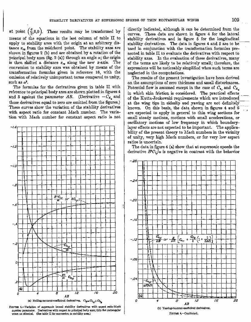
The formulas for the derivatives givem in table II withreference to principal body axes are shown p~otted in figures 4and 5 against the parameter M?. (Derivative —CXM ~dthose derivatives equal to zero are omitted from the figures.)These curves show the variation of the st.abiIityderivativeswith aspect ratio for constant Mach number. The vmia-tion with Mach number for constant aspect ratio is not
Hdbk-Ftt_‘.. c~a
I.2 \ K
1 ‘
@ 1
0 4 8 12 f6 20AB
(a) RoUfn&moment-coetEcIentderivatf- ct~.crlfl+~g
Fmmx 4.–Varfatlcm of superaonlcIaterd stabUfty derhtks with espect ratfc-Mnehnumberparwneter. Deihatives with respectto prfndpalL@ q thh fit raeWguMwlnr no dthedrd. (SeetableIi forconmrsionto atabllt~ axes.)
directly indicated, although it can be determined from thecurves. These data are shown in figure 4 for the lateralstability derivatives and in figure 5 for the longitudinalstability derivatives. The data in figures 4 and 5 are to beused in conjunction with the transformation formulas pre-sented in table II to evaluate the derivatives with respect tostability axes. In the evaluation of these derivatives, manyof the terms are likely to be relatively small; therefore, theexpressionsVW be noticeably simpli6ed when such terms arenegkcted in the computations.
The results of the present investigation hare been derivedon the assumptions of zero thiclmess and small disturbances.Potential flow is assumed except in the case of Carand CXXin vrhich skin friction is considered. The practical effec~of the KuttaJoukowki requirements which are introducedat the wing tips in sidedip and yawing are not detkiitelyknown. On this basis, the data shown in figures 4 and 5 ,are expected to apply in generaI to thin wing sections forsmall steady motions, motions with small accelerationa, oroscillatory motions of low frequency in which boundary-layer tiects are not expected to be important. The applica-bility of the present theory to Mach numbers in the vicinityof unity, wry high Mach numbers, or for very low aspectratios is uncertain.
The data in figure 4 (a) show that at supersonic speeda thederivative BVIJLXis negative in contrast with the behavior
-.&w
-24
-20
‘./6
-.12
-.08
-.04
0 4 8 12 16 20AB
(b) Yawing-moment-me5cfentderivatkw.
FIGU’JXL–Ciontlnue&
110 REPORT 92 5—NATIONAL ADVIS~~Y CO~EE FOR -MIRONitiICS
2.8
2.4
2.0
1.6
1.2
B
.4
0 4 8 /2 /6 20AB
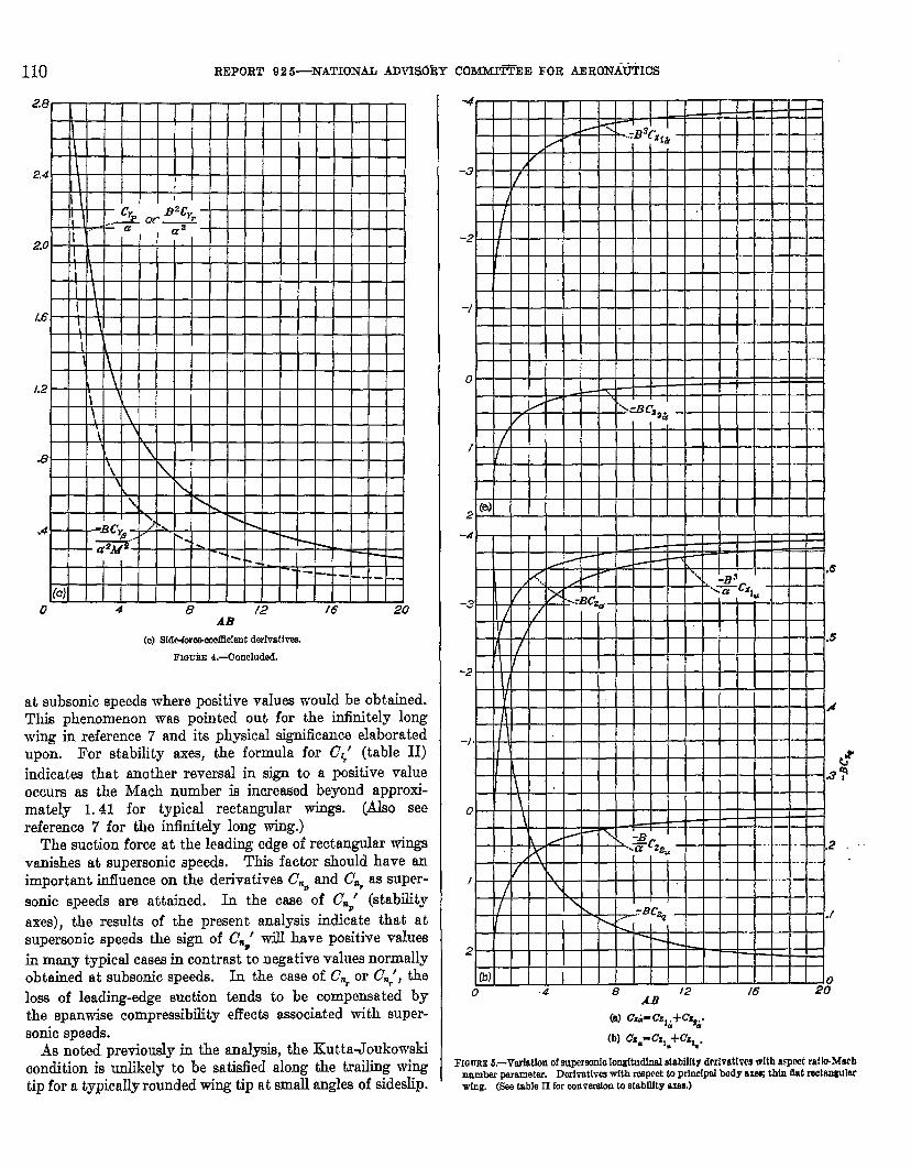
(c)Sfd+forc&metlldentdwhatlves.
FI@UnE4.~Concluded.
at subsonic speeds where positive values would be obtained.This phenomenon was pointed out for the infinitely longwing in reference 7 rind its physical significance elaboratedupon. For stability axes, the formula for C;’ (table 11)indicates that another reversal in sign to a positive value
occurs as the Mach number is increased beyond approxi-mately 1.41 for typicaI rectangular wings. (Also seereference 7 for the infinitely long wing.)
The suction force at the leading edge of rectangular wingsvanishes at supersonic speeds. This factor should have ~important iofIuence on the derivatives C~=and C~, as super-sonic speeds are attained. In the case of C~P’ (stabfity
axes), the results of the present analysis indicate that atsupersonic speeds the sign of Cm‘ will have positive valuea
in many typical cases in contrast 10 negative values normalIyobtained at subsonic speeds. In the case of C., or cm,’, the
loss of leadirtg-edge suction tenda to be compensated bythe spanwiae compressibility effects associated with super-sonic speeds.
As noted previously in the anal@, the KuttaJoukowskicondition is unlikely to be satisfied along the trailing wingtip for a typically rounded wing tip at small angles of sideelip.
(B) c&-cs%+cz%.
(b) CZW-CZ,.+CZ%.
FI~Tr~ES.–VarfaUonof ewmeonfoIonghffnd stabilkg drrivat[wwwltlIaqxwt ratbM,@number perwaeter. Dorhtlws wftir respect ta princ[palbody ax+ thin flutroctnngulerwfng. (Seatable11forwnvwdon w stsbillty am.)
STABILITY DERIVATIVES AT SUPERSONIC
0“ 4 8 {2 [6 20AB’
(d ~imc.,i+c.z;.
(@ c..- C.,=+cy(
FIGUBX S.-corduded.
SPEEDS OF ‘lLKIN RECLKNGULAR WINGS 111
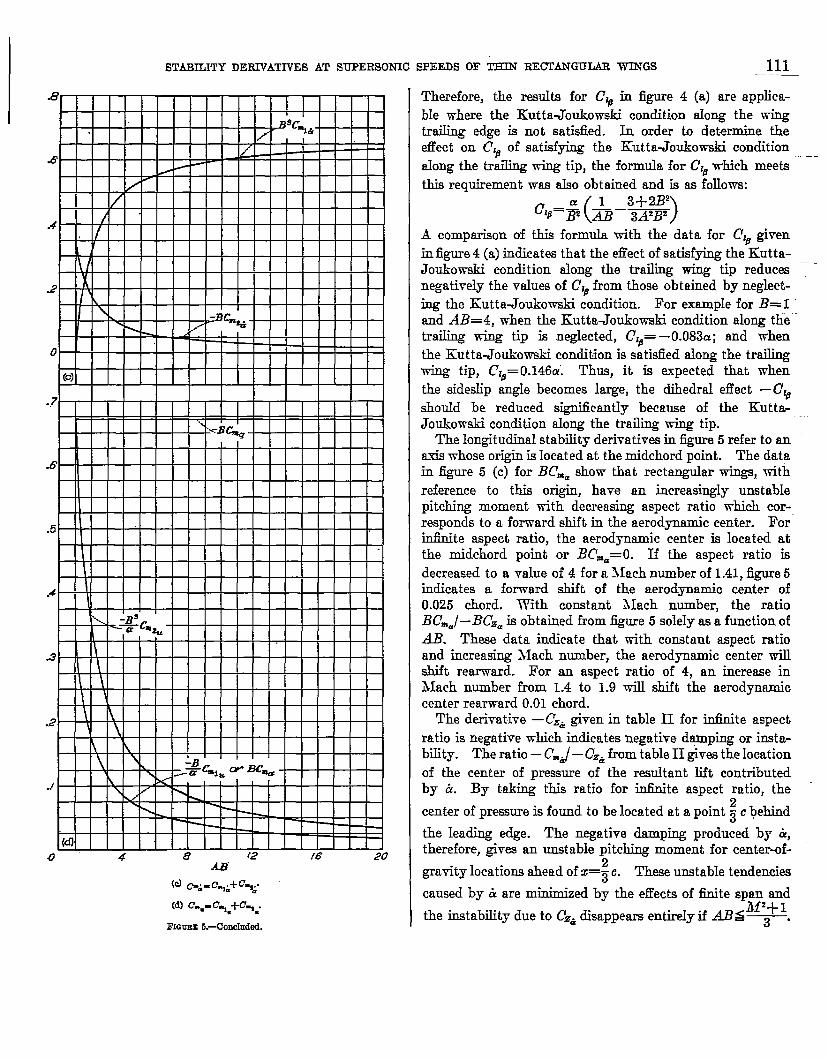
Therefore, the rcmdts for C% in figure 4 (a) are applica-ble where the Kutta-Joukowski condition aIong the wingtraiIing edge is not satisfied. In order to determine theefTect on C% of satisfying the Kut ta-Joukowski conditionaIong the traiIing wing tip, the formula for Cl~which meets ‘-this requirement -wasalso obtained and is as follows:
A comparkon of this formula with the data for Cle givenin figure 4 (a) indicates that the eflect of satisfying the Kutta-Joukowsk.i condition along the trailing wing tip redu&snegatively the vahes of C%from those obtBined by neglect-ing the KuttaJoukowaki condition. For emunple for B= Iand AB=4, when the Kutta-Joukowski condition along thetrailing wing tip is neglected, (?16=—0.083a; and whenthe Kutta-Joukowski condition is satisfied along the trailing- tip, dZd=0.146Ci Thus, it is expected that whenthe sideelip angle becomes large, the dihedral effect –C,dshould be reduced significady because of the Kutta-Joukowski condition along the trailing wing tip.
The longitudinal stability derivativ~ in figure 5 refer to anaxis whose origin is locat ed at the midchord point. The datain @e 5 (c) for B~=mshow that rectangular wings, withreference to this origin, have an increasingly unstablepitching moment with decreasing aspect ratio which cor-responds to a forward shift in the aerodynamic center. For”infinite aspect ratio, the aerodynamic center is located atthe midchord point or BCm==O. If the aspect ratio isdecreased to a value of 4 for a Mach number of 1.41, figure 5indicates a forward shift of the aerodynamic center of0.025 chord. With constant Mach number, the ratioBC.=/–BC.a is obtained from figure 5 solely as a function ofAll. These data indicate that tith constant aspect ratioand increasing Mach number, the aerodynamic center willshift rearward. For an aspect ratio of 4, an increase inMach number from 1.4 to 1.9 will shift the aerodynamiccenter rearviard 0.01 chord.
The derivative – Cz&given in table II for irdinite aspectratio is negative which indicates negative damping or insta-bility. The ratio – C’.J– Cz&from table II ~ve.s the locationof the center of pressure of the resultant lift contributedby & By taking this ratio for in6uite aspect ratio, the
center of pressure is found to be located at a point ~ c behind
the leading edge. The negative damping produced by ~,therefore, gives an unstable pitching moment for center-of-
gravity Iocations ahead of x=; c. These unstable tendencies
caused by & are minimized by the effects of finite span andill’+ 1
the instability due to C.&disappears entireIy if ABS~

112 REPORT 92 6—NATIONAL ADVfSORY
CONCLUS1ONS
A theoretical investigation has been made by means ofthe linearized theory to obtain formulas for the surface-veIocit y-potential functions, surface-pressure distributions,and stabiIity derivatives for various motions at supersonicspeeds for rectangular wings of zero thickness withoutdihedral. The investigation included steady and accelerat-ing vertical and longitudinal motions and steady rolling,yawing, sideslipping, and pitching for Mach numbers andaspect ratios greater than those for which the Mach linefrom the leading edge of the tip section intersects the trailingedge of the opposite tip section.
The fo~owing sigrdicant conclusions have been obtainedfor this investigation:
1. At supersonic speeds for Mach numbers emalIer thanapproximately 1.41, positive yawing generally results in anegative roMng moment in contrast to the behavior at sub-sonic speeds where a positive rolling moment is produced.
2. The attainment of supersonic speed produces a sigrM-cant change in the positive direction of the yawing momentper unit rolling velocity.
3. For infinite aspect ratio, a constant vertical accelera-tion causes a negative damping in the vertical motion, andan unstable pitching moment for center-of-gravity locations
ahead of the ~ -chord point. These unstable tendencies are
minimized by the effects of finite span and the instabilitydue to the rate of change of Iift with vertical acceleration
disappears entirely if A~~Is ‘~ where A is the
aspect ratio and itf is the hfach number.
LANGLEY AERONAUTICAL LABORATORY,
NATIONAL ADVISORY COMMI~EE FOR AERONAUTICS,
LANGLEY FIELD, VA,, June 30, 1948,
COMMITTEE FOR AERONAUTICS
1.
2.
i3.
4.
6.
e.
7.
8.
9.
10,
REFERENCES
Puckett, Alien E.: Supersonic Wave Drag of Thin Airfoils. Jour.Aero. Sci., vol. 13, no. 9, Sept. 1946, pp. 475-484.
Jones, Robert T.: Properties of Low-Aspect-Ratio Pointod Win&at Spseds below and abovo the Speed of Sound. NACA Rep.835,1946.
Brown, CIinton E.: Theoretical Lift and Drag of Thin Trim@arWhge at Supersonic Speeds. NACA Rep. 839, 1946.
Eward, John C?.:Distribution of Wave Drag and Lift in theVicinity of Wing Tips at Superaorda Spocds. NACA TN 1382,1947.
Ribner, Herbert S.: The Stability Derivatives of Low-Aspcct-Ratio Triangular Wings at Subsonio and SupmaonIo Spec&.NACA TN 1423, 1947.
Brown, Clinton E., and Adams, Mao C.: Damping in Pitch andRolIlf Triangular Wings at Supersonic Speeds, NACA Rep.892, 1948.
Ribner, Herbert S., an-d Malvestuto, Frank S., Jr.: std)~]ity
Dofivatives of Triangular Wings at Supersonic Speeds. NACATN 1672, 1948.
Moockel,W. E.: Effect of Yaw at Supersonic Spccde on ThcorctLcal Aerodynamic Coefficientsof Thin Pointed Wingswith SeveralTypes of Trailing Edge. NACA TN 1549, 194S.
Jones, Arthur L., and Alksne, Alberta: The Damping Duo toRo~ of Triangular, Trapezoidal, and Related Plan Forms inSurm,isonic Flow. NACA TN 1548, 1948.
Evv~d. John C.: A Linearized Solution for Time-DcrnmdcntVelo~ty Potentials near Three-DimcnaionnI Wings at_ Su~wr-sonic Speeds. NACA TN 1699, 1948.
11. Evvard, John C.: Theoretical Distribution of Iift on Thin Wingsat Supersonic Speeds (An Extension). NACA TN 1585, 10M!.
12. Evvard, John C., and Turner, L. Richar& Theoretical Lift Dis-tribution and Upwash Velocitiw for Thin Wings at supersonicSpeeds, NACA TN 1484, 1947.
13, Peirce, B, O.: A Short Table of Integrals. Third rev. cd., Ginnand Co., 1929.
14. Garric& I. E., and Rubinow, S. I.: Flutter and Oscillating A1r-Force Calculations for an Airfoil in Two-Dimensional Super-eonio Flow. NACA Rep. 846, 1946.
15. Von KArmdn, Th., and Burgem, J. M.: General AerodynamicTheory—Perfect FIuids. Theory of Airplane Wings of InfinitoSpan. VO1. II of Aerodynamic Theory, div. E, ch. II, sec. 10,TV.F. Durand, cd., Julius Springer (Berlin), 1!13fi,pp. 48-53.
16. Glauert, H.: A Non-Dimensional Form of the Stability Equa-tions of an Aeroplane. R.& hf, No. 1093, British A.R. C., 1927.
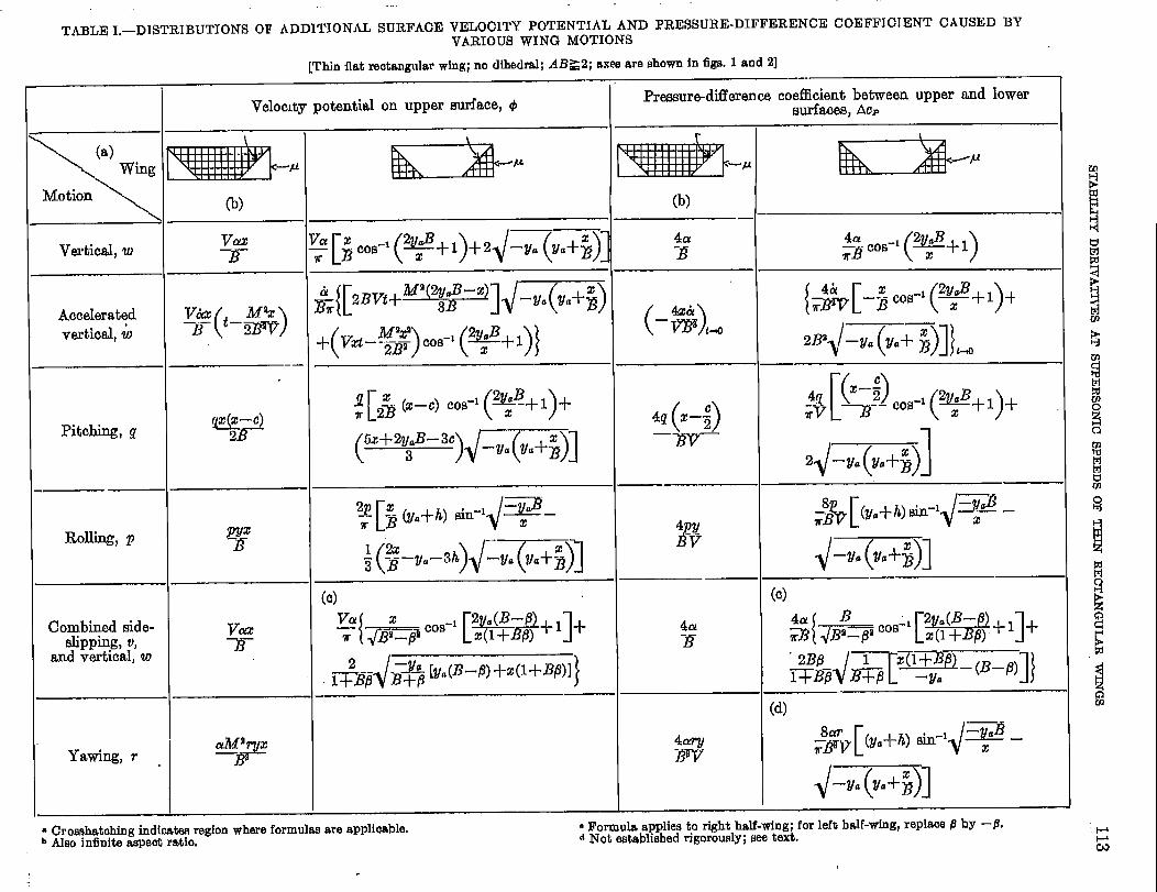
TABLE 1.—I3ISTRIBITTIONS OF ADDITIONfi SURFACE VELOCITY POTENTIAL AND PRESSURE-DIFFERENCE COEFFICI ENT CAUSED BYVARIOUS WING MOTIONS
[Thin flat rectangular wing; no dihedral; ABZ2; axes are shown in figs, 1 and 2]
Veloc~ty potential on upper surface, +Pressure-difference coefficient between upper and lower
wrfa(xs, AOF
BiL2ia-”111111111 \
\
(a)
wing
Motion\
Vmtical, w
Accelemt$vertical, w
Pitching, g
Rolling, p
%’0’-’(%+1)tla
3
()4x&‘w km
[$ & (x–c) Cos-’(*E+l)+(“+2TB-3’)GT%I
()4q x–;
—m—
4y1
. .v‘pyX
-E
Combined ~icle-slipping, u,
and vert~cal, w
Yawing, r
(d)
41%ry-m
aiw x&—
~ Rmmula applies to right half-wing; for left half-wing, replaee P by -9.~ Not established rigorously; see text.
● Cr omhatohing fndicab region where formulss are applicable.b Also infinite aspeot ratio.
.

114 REPORT 925—NATLONAL ADVISORY COMMITTEE FOR AERONAUTICS
TABLE 11.-STABILITY DERWATIVES OF THIN FLAT RECTANGULAR WINGS WITHOUT DIHEDRAL AT SUPERSONIC SPEEDS
Prhmipal body axes StabiIity axea
( “’ig~a’po’%,o,o)) .( (origin at dietance z., measured positive ahead of midchord point ~-z.,, O,0
)).
Stabilityderivative Formula Stability
derivative I Formula
Lateral .—
c~(
12 1 1–z 3–a+m+& )
cl,’ c~+a p’r+c%–~ (Zclp+ %)]
CJB(
a l–B~ 3+B..”
)_—
~a ~ 3A21Pc,;
(G;+ ff C.B–x$ (gyB
)
(‘~ :–A~+&+&’ ) [c%’ cl,–% Clfl-a c~– cn,+x~(c,r+2cnfl)-~C,fl– av~0,, 1
c% (8Ba 1
)3U A2B2 &c%’
[–$ Cy,–a c,,– 1_%c!~yfl_c%+~(cY,+ 2GB) ~2~2————% fjA
(c? CG–25 Clb
)“
C.B4a?M~
Cq’ !% (JYfl3=-ASBZ — CYclb
( —&)-%(”a) cn~ “naJJ:J+2@’P+c%
‘3> A2B2 3A8BS8* 1
a[ 1
– ch–cn,+~ (2c#b+cY,)-@w,
C,p (16a 1
)~ ~& Cy,’ (c.,+ a C,r– ~ cYfl)
Gfl8c#M2
Crfl’ GflTABi
C.r (16c? 1 4
)0,; ‘“ CyB–acyp2?% m–mm 0=,–=
Longitudinal
c 1 Cma’ cma ~ % —ac%+y (Cza— CYczu)
c% –& (M’+1) c%’ C%+aGa+~ (dza+c%)
c % –ii cm;()
C.*+2 ~ ‘Cze
c w &@-%? cm:cm.+y Czb
cw Cmti’ (a Cmh+ C&i)
– CzaL?)
1 – c.a’ CYczw–C.m2 .– czu & (M’+1–2AB) – czu’ –CZU+CY(CXU–CZJ
– c., 2 +’ – c.,–+ Cza3AIY
– Cza b ( 1–4+5#- – czk’ – cz&
– Czd o“ – czd’ — CYoz&–O.= o – cx=’ a(cxti–CZJ+ CFczu– C.u 2CD0 – cxu’ – Cxu–aczu–dcz=
– c., o – c=,’ (—a cze+~ Q )a–C& o –cxk’ — Cxcz&– G& o –c.*’ –C#t51z&