sinamics s120 cabinet modules - siemens · cabinet modules manual, (gh5), 03/2011, a5e03263538a 3...
TRANSCRIPT
Manual · 03/2011
SINAMICS S120 Cabinet Modules
SINAMICS
s

Cabinet Modules
___________________
___________________
___________________
___________________
___________________
___________________
___________________
___________________
___________________
SINAMICS
S120 Cabinet Modules
Manual
(GH5), 03/2011 A5E03263538A
Preface
Safety information 1
System overview 2
Mechanical installation 3
Electrical installation 4
Cabinet Modules 5
Maintenance and servicing 6
Diagnostics 7
Options 8
Legal information
Legal information Warning notice system
This manual contains notices you have to observe in order to ensure your personal safety, as well as to prevent damage to property. The notices referring to your personal safety are highlighted in the manual by a safety alert symbol, notices referring only to property damage have no safety alert symbol. These notices shown below are graded according to the degree of danger.
DANGER indicates that death or severe personal injury will result if proper precautions are not taken.
WARNING indicates that death or severe personal injury may result if proper precautions are not taken.
CAUTION with a safety alert symbol, indicates that minor personal injury can result if proper precautions are not taken.
CAUTION without a safety alert symbol, indicates that property damage can result if proper precautions are not taken.
NOTICE indicates that an unintended result or situation can occur if the relevant information is not taken into account.
If more than one degree of danger is present, the warning notice representing the highest degree of danger will be used. A notice warning of injury to persons with a safety alert symbol may also include a warning relating to property damage.
Qualified Personnel The product/system described in this documentation may be operated only by personnel qualified for the specific task in accordance with the relevant documentation, in particular its warning notices and safety instructions. Qualified personnel are those who, based on their training and experience, are capable of identifying risks and avoiding potential hazards when working with these products/systems.
Proper use of Siemens products Note the following:
WARNING Siemens products may only be used for the applications described in the catalog and in the relevant technical documentation. If products and components from other manufacturers are used, these must be recommended or approved by Siemens. Proper transport, storage, installation, assembly, commissioning, operation and maintenance are required to ensure that the products operate safely and without any problems. The permissible ambient conditions must be complied with. The information in the relevant documentation must be observed.
Trademarks All names identified by ® are registered trademarks of Siemens AG. The remaining trademarks in this publication may be trademarks whose use by third parties for their own purposes could violate the rights of the owner.
Disclaimer of Liability We have reviewed the contents of this publication to ensure consistency with the hardware and software described. Since variance cannot be precluded entirely, we cannot guarantee full consistency. However, the information in this publication is reviewed regularly and any necessary corrections are included in subsequent editions.
Siemens AG Industry Sector Postfach 48 48 90026 NÜRNBERG GERMANY
A5E03263538A 05/2011
Copyright © Siemens AG 2011. Technical data subject to change
Cabinet Modules Manual, (GH5), 03/2011, A5E03263538A 3
Preface
Information on the SINAMICS S120 documentation The SINAMICS S120 documentation is subdivided into the following levels:
General documentation/catalogs
Manufacturer/service documentation
Electronic documentation
This documentation is part of the manufacturer/service documentation for SINAMICS. All of the documents are available individually.
Please contact your local Siemens office for further information about other available SINAMICS publications.
For the sake of simplicity, this documentation does not contain comprehensive detailed information about all types of the product and cannot cover every conceivable case of installation, operation, or maintenance.
The contents of this documentation are not part of an earlier or existing agreement, a promise, or a legal agreement, nor do they change this. The Purchase Agreement contains the complete and exclusive obligations of Siemens, including the warranty provisions. These contractual warranty provisions are neither extended nor curbed as a result of the statements made in this documentation.
Audience This documentation is aimed at machine manufacturers, plant engineers, commissioning engineers, and service personnel who use SINAMICS.
Objective This manual describes the hardware components and design of the SINAMICS S120 Cabinet Modules. It provides information about installation, electrical connection, and cabinet design.
Preface
Cabinet Modules 4 Manual, (GH5), 03/2011, A5E03263538A
Technical support If you have any questions, please contact our hotline:
Time zone Europe and Africa
Phone +49 (0) 911 895 7222 Fax +49 (0) 911 895 7223 Internet http://www.siemens.com/automation/support-request
Time zone America
Phone +1 423 262 2522 Fax +1 423 262 2200 E-mail [email protected]
Time zone Asia/Pacific
Phone +86 1064 757 575 Fax +86 1064 747 474 E-mail [email protected]
Note
Country-specific telephone numbers for technical support are provided at the following Internet address:
http://www.automation.siemens.com/partners
Internet addresses Up-to-date information about our products can be found on the Internet at the following address: http://www.siemens.com
Information about SINAMICS S120 Cabinet Modules can be found under: http://www.siemens.com/sinamics-s120-cabinet-modules
Cabinet Modules Manual, (GH5), 03/2011, A5E03263538A 5
Table of contents
Preface ...................................................................................................................................................... 3
1 Safety information.................................................................................................................................... 15
1.1 Requirements...............................................................................................................................15
1.2 Electrostatic sensitive devices (ESD) ..........................................................................................16
1.3 Safety information ........................................................................................................................17
1.4 Residual risks...............................................................................................................................19
2 System overview...................................................................................................................................... 21
2.1 Overview ......................................................................................................................................21
2.2 Field of application .......................................................................................................................23
2.3 Benefits ........................................................................................................................................23
2.4 Line Modules................................................................................................................................24 2.4.1 General information .....................................................................................................................24 2.4.2 Basic Line Modules......................................................................................................................24 2.4.3 Smart Line Modules .....................................................................................................................26 2.4.4 Active Line Modules.....................................................................................................................27
2.5 DC link components.....................................................................................................................28 2.5.1 Braking Modules as an option for a Motor Module or a Line Module ..........................................28 2.5.2 Central Braking Modules..............................................................................................................28
2.6 Motor Modules .............................................................................................................................29 2.6.1 Booksize Base Cabinets with Booksize Cabinet Kits ..................................................................29 2.6.2 Chassis Cabinets .........................................................................................................................29
2.7 Auxiliary Power Supply Modules..................................................................................................29
2.8 Overview of options .....................................................................................................................30
2.9 System structure ..........................................................................................................................32
2.10 System data .................................................................................................................................33
2.11 Derating data................................................................................................................................35 2.11.1 Derating data for booksize format................................................................................................35 2.11.2 Derating data for chassis format..................................................................................................35 2.11.2.1 General ........................................................................................................................................35 2.11.2.2 Derating measures.......................................................................................................................36
3 Mechanical installation............................................................................................................................. 39
3.1 Important notes ............................................................................................................................39
3.2 Mechanical installation: Checklist ................................................................................................42
3.3 Installation....................................................................................................................................44 3.3.1 Important safety precautions........................................................................................................44 3.3.2 Preparatory steps.........................................................................................................................44
Table of contents
Cabinet Modules 6 Manual, (GH5), 03/2011, A5E03263538A
3.3.2.1 On-site requirements................................................................................................................... 44 3.3.2.2 Requirements on the levelness of the floor................................................................................. 46 3.3.2.3 Shipping and handling indicators ................................................................................................ 47 3.3.2.4 Unpacking the cabinets............................................................................................................... 49 3.3.2.5 Tools required ............................................................................................................................. 49 3.3.3 Lifting the cabinet units off the transport pallet and installing them ............................................ 50 3.3.4 Disassembling the crane transport assembly ............................................................................. 51 3.3.5 Connection to the foundation ...................................................................................................... 53 3.3.6 Connection for side-by-side installation of cabinet units............................................................. 53
4 Electrical installation ................................................................................................................................ 55
4.1 Safety information ....................................................................................................................... 55
4.2 Electrical installation: Checklist ................................................................................................... 56
4.3 EMC-compliant design ................................................................................................................ 61
4.4 Connecting shielded three-phase cables.................................................................................... 62
4.5 Connections ................................................................................................................................ 63 4.5.1 Connection overview................................................................................................................... 63 4.5.2 PE busbar.................................................................................................................................... 64 4.5.2.1 General information..................................................................................................................... 64 4.5.2.2 Connection for side-by-side installation of cabinet units............................................................. 64 4.5.2.3 Connection according to the system-side grounding concept .................................................... 66 4.5.2.4 Connecting external cables to the PE busbar............................................................................. 66 4.5.3 DC busbar ................................................................................................................................... 67 4.5.3.1 General information..................................................................................................................... 67 4.5.3.2 Connection for side-by-side installation of cabinet units............................................................. 67 4.5.4 Auxiliary power supply system.................................................................................................... 70 4.5.4.1 General information..................................................................................................................... 70 4.5.4.2 Connection overview................................................................................................................... 75 4.5.4.3 Connection for side-by-side installation of cabinet units............................................................. 76 4.5.4.4 Connecting to the infeed ............................................................................................................. 77 4.5.5 Connecting the motor cables ...................................................................................................... 78 4.5.6 Line supply connections.............................................................................................................. 81 4.5.7 Adjusting the fan voltage............................................................................................................. 82 4.5.8 Connecting Cabinet Modules to non-grounded line supplies (IT systems) ................................ 84 4.5.9 Signal connections ...................................................................................................................... 92 4.5.10 Other connections ....................................................................................................................... 92 4.5.11 Cable routing............................................................................................................................... 92 4.5.11.1 General information..................................................................................................................... 92 4.5.11.2 Cable routing for Line Connection Modules................................................................................ 94 4.5.11.3 Cable routing for Basic Line Modules ......................................................................................... 97 4.5.11.4 Cable routing for Smart Line Modules ...................................................................................... 101 4.5.11.5 Cable routing for Active Line Modules ...................................................................................... 105 4.5.11.6 Cable routing for Booksize Base Cabinets and Booksize Cabinet Kit ...................................... 112 4.5.11.7 Cable routing for Motor Modules in the chassis format ............................................................ 112 4.5.11.8 Cable routing for Central Braking Modules ............................................................................... 119 4.5.11.9 Cable routing for Auxiliary Power Supply Modules................................................................... 121
Table of contents
Cabinet Modules Manual, (GH5), 03/2011, A5E03263538A 7
5 Cabinet Modules.................................................................................................................................... 123
5.1 Line Connection Modules ..........................................................................................................123 5.1.1 General information ...................................................................................................................123 5.1.2 Description .................................................................................................................................124 5.1.2.1 Fuse switch disconnector (input current ≤ 800 A) .....................................................................127 5.1.2.2 Circuit breaker (input current > 800 A).......................................................................................127 5.1.2.3 Terminal block -X40 external 230 V AC auxiliary infeed ...........................................................129 5.1.3 Versions of Line Connection Modules .......................................................................................130 5.1.3.1 Version L42 for Active Line Modules .........................................................................................130 5.1.3.2 Version L43 for Basic Line Modules ..........................................................................................131 5.1.3.3 Version L44 for Smart Line Modules .........................................................................................133 5.1.4 Options.......................................................................................................................................135 5.1.5 Technical data............................................................................................................................136
5.2 Basic Line Modules....................................................................................................................140 5.2.1 General information ...................................................................................................................140 5.2.2 Description .................................................................................................................................140 5.2.3 Interface description...................................................................................................................145 5.2.3.1 General information ...................................................................................................................145 5.2.3.2 Control Interface Module............................................................................................................145 5.2.3.3 X41 EP terminal / temperature sensor connection ....................................................................146 5.2.3.4 DRIVE-CLiQ interfaces X400, X401, X402................................................................................147 5.2.4 Options.......................................................................................................................................148 5.2.5 Technical data............................................................................................................................149
5.3 Smart Line Modules ...................................................................................................................153 5.3.1 General information ...................................................................................................................153 5.3.2 Description .................................................................................................................................153 5.3.3 Interface description...................................................................................................................159 5.3.3.1 General information ...................................................................................................................159 5.3.3.2 Control Interface Module............................................................................................................159 5.3.3.3 X41 EP terminal / temperature sensor connection ....................................................................160 5.3.3.4 DRIVE-CLiQ interfaces X400, X401, X402................................................................................161 5.3.4 Options.......................................................................................................................................162 5.3.5 Technical data............................................................................................................................163
5.4 Active Line Modules...................................................................................................................167 5.4.1 General information ...................................................................................................................167 5.4.2 Description .................................................................................................................................167 5.4.3 Interface description...................................................................................................................175 5.4.3.1 General information ...................................................................................................................175 5.4.3.2 Control Interface Module............................................................................................................175 5.4.3.3 X41 EP terminal / temperature sensor connection ....................................................................176 5.4.3.4 DRIVE-CLiQ interfaces X400, X401, X402................................................................................177 5.4.4 Options.......................................................................................................................................178 5.4.5 Technical data............................................................................................................................179
5.5 Booksize format Motor Modules ................................................................................................185 5.5.1 General information ...................................................................................................................185 5.5.2 Description .................................................................................................................................185 5.5.3 Interface description...................................................................................................................191 5.5.3.1 General information ...................................................................................................................191 5.5.3.2 Customer terminal block X55.1..................................................................................................191 5.5.4 Options.......................................................................................................................................193
Table of contents
Cabinet Modules 8 Manual, (GH5), 03/2011, A5E03263538A
5.5.5 Technical data........................................................................................................................... 194 5.5.6 Overload capability.................................................................................................................... 198
5.6 Chassis format Motor Modules ................................................................................................. 199 5.6.1 General information................................................................................................................... 199 5.6.2 Description ................................................................................................................................ 199 5.6.3 Interface description.................................................................................................................. 207 5.6.3.1 General information................................................................................................................... 207 5.6.3.2 Control Interface Module........................................................................................................... 207 5.6.3.3 X41 EP terminal / temperature sensor connection ................................................................... 208 5.6.3.4 X46 Brake control and monitoring............................................................................................. 209 5.6.3.5 DRIVE-CLiQ interfaces X400, X401, X402............................................................................... 209 5.6.4 Options ...................................................................................................................................... 210 5.6.5 Technical data........................................................................................................................... 212 5.6.6 Overload capability.................................................................................................................... 221
5.7 Central Braking Modules........................................................................................................... 223 5.7.1 General information................................................................................................................... 223 5.7.2 Description ................................................................................................................................ 223 5.7.3 Interfaces................................................................................................................................... 228 5.7.4 Options ...................................................................................................................................... 233 5.7.5 Technical data........................................................................................................................... 234 5.7.6 Derating data............................................................................................................................. 235 5.7.7 Braking resistor ......................................................................................................................... 236 5.7.7.1 Description ................................................................................................................................ 236 5.7.7.2 Safety information ..................................................................................................................... 237 5.7.7.3 Duty cycle.................................................................................................................................. 238 5.7.7.4 Interfaces on the braking resistor.............................................................................................. 239 5.7.7.5 Configuring the "Overtemperature" checkback......................................................................... 239 5.7.7.6 Technical data........................................................................................................................... 240
5.8 Auxiliary Power Supply Modules............................................................................................... 243 5.8.1 General information................................................................................................................... 243 5.8.2 Description ................................................................................................................................ 244 5.8.3 Fuse switch disconnector (-Q1) ................................................................................................ 248 5.8.4 Transformer (-T2) for generating the auxiliary voltage 230 V AC............................................. 248 5.8.5 Auxiliary power supply system.................................................................................................. 250 5.8.6 Customer interfaces for supplying power to an additional auxiliary power supply system....... 251 5.8.7 Options ...................................................................................................................................... 252 5.8.8 Technical data........................................................................................................................... 253
6 Maintenance and servicing .................................................................................................................... 255
6.1 Chapter content......................................................................................................................... 255
6.2 Cleaning the cabinet ................................................................................................................. 256
6.3 Servicing the cabinet................................................................................................................. 256
6.4 Replacing components.............................................................................................................. 258 6.4.1 General information................................................................................................................... 258 6.4.2 Safety information ..................................................................................................................... 259 6.4.3 Installation device for power blocks .......................................................................................... 260 6.4.4 Replacing the filter mats............................................................................................................ 261 6.4.5 Replacing power units............................................................................................................... 263 6.4.6 Replacing the Motor Module, booksize format.......................................................................... 264
Table of contents
Cabinet Modules Manual, (GH5), 03/2011, A5E03263538A 9
6.4.7 Replacing the power block, chassis format ...............................................................................265 6.4.7.1 Replacing the power block, frame size FB ................................................................................265 6.4.7.2 Replacing the power block, frame sizes GB and GD.................................................................268 6.4.7.3 Replacing the power block, frame size FX ................................................................................271 6.4.7.4 Replacing the power block, frame size GX................................................................................274 6.4.7.5 Replacing the power block, frame size HX ................................................................................277 6.4.7.6 Replacing the power block, frame size JX.................................................................................282 6.4.8 Replacing the Control Interface Module ....................................................................................284 6.4.8.1 Replacing the Control Interface Module, frame size FX ............................................................284 6.4.8.2 Replacing the Control Interface Module, frame size GX ...........................................................286 6.4.8.3 Replacing the Control Interface Module, frame size HX............................................................288 6.4.8.4 Replacing the Control Interface Module, frame size JX ............................................................290 6.4.9 Replacing the Control Unit .........................................................................................................292 6.4.10 Replacing the fans .....................................................................................................................293 6.4.10.1 Replacing the fan, Booksize Cabinet Kit....................................................................................293 6.4.10.2 Replacing the fan, frame sizes FB, GB and GD ........................................................................297 6.4.10.3 Replacing the fan, sizes FX and GX..........................................................................................299 6.4.10.4 Replacing the fan, size HX.........................................................................................................301 6.4.10.5 Replacing the fan, frame size JX ...............................................................................................305 6.4.10.6 Replacing the fan, frame size FI ................................................................................................307 6.4.10.7 Replacing the fan, frame size GI................................................................................................309 6.4.10.8 Replacing the fan, frame size HI................................................................................................311 6.4.10.9 Replacing the fan, frame size JI.................................................................................................313 6.4.11 Replacing the fuses ...................................................................................................................315 6.4.11.1 Replacing the fuses for the auxiliary power supply....................................................................315 6.4.11.2 Replacing the fuses (F71 to F73) in the Line Connection Module.............................................316 6.4.11.3 Replacing fuses in the fuse switch disconnector for Booksize Cabinet Kit ...............................317 6.4.11.4 Replacing the DC fuses for the Motor Module, chassis format .................................................318 6.4.11.5 Replacing the encapsulated fuses.............................................................................................320 6.4.11.6 Replacing the LV HRC fuses .....................................................................................................321 6.4.12 Replacing the DC interface (option L37)....................................................................................322 6.4.13 Replacing the pre-charging resistors of the DC interface (option L37)......................................323 6.4.14 Replacing the backup battery for the cabinet operator panel ....................................................324
6.5 Forming the DC link capacitors..................................................................................................326
7 Diagnostics ............................................................................................................................................ 331
7.1 Chapter content .........................................................................................................................331
7.2 LEDs on the CU320-2 DP Control Unit......................................................................................331
7.3 LEDs on the CU320-2 PN Control Unit......................................................................................335
7.4 LEDs on the CBE20 Communication Board ..............................................................................338
7.5 LEDs on the Control Interface Module in the Basic Line Module ..............................................340
7.6 LEDs on the Control Interface Module in the Smart Line Module .............................................341
7.7 LEDs on the Control Interface Module in the Active Line Module .............................................342
7.8 LEDs on the Control Interface Module in the Motor Module, chassis format ............................343
7.9 LEDs on the Motor Module in the booksize format....................................................................344
7.10 LEDs on the Central Braking Module ........................................................................................345
7.11 LEDs on the Voltage Sensing Module (VSM) in the Active Interface Module ...........................346
Table of contents
Cabinet Modules 10 Manual, (GH5), 03/2011, A5E03263538A
7.12 LEDs on the SMC10 Sensor Module ........................................................................................ 347
7.13 LEDs on the SMC20 Sensor Module ........................................................................................ 348
7.14 LEDs on the SMC30 Sensor Module ........................................................................................ 349
7.15 LEDs on the TM54F Terminal Module ...................................................................................... 350
7.16 LEDs on the SITOP power supply unit ..................................................................................... 350
8 Options .................................................................................................................................................. 351
8.1 Safety information ..................................................................................................................... 351
8.2 D14, Preliminary copy of customer documentation .................................................................. 352
8.3 G20, CBC10 Communication Board ......................................................................................... 353
8.4 G33, CBE20 Communication Board ......................................................................................... 356
8.5 G55, customer terminal block ................................................................................................... 359 8.5.1 General information................................................................................................................... 359 8.5.2 Interfaces................................................................................................................................... 360 8.5.2.1 Overview ................................................................................................................................... 360 8.5.2.2 X41 EP terminal / temperature sensor connection ................................................................... 362 8.5.2.3 X46 Brake control and monitoring............................................................................................. 363 8.5.2.4 X122 digital inputs/outputs ........................................................................................................ 364 8.5.2.5 X132 digital inputs/outputs ........................................................................................................ 366
8.6 G56, contactor feedback signal, S120 Cabinet Modules.......................................................... 368
8.7 K01 to K05, safety license for 1 to 5 axes................................................................................. 369
8.8 K08, AOP30 advanced operator panel ..................................................................................... 371
8.9 K46, Sensor Module Cabinet-Mounted SMC10........................................................................ 373 8.9.1 General information................................................................................................................... 373 8.9.2 Safety information ..................................................................................................................... 374 8.9.3 Interfaces................................................................................................................................... 375 8.9.4 Connection example ................................................................................................................. 377
8.10 K48, Sensor Module Cabinet-Mounted SMC20........................................................................ 378 8.10.1 General information................................................................................................................... 378 8.10.2 Safety information ..................................................................................................................... 378 8.10.3 Interfaces................................................................................................................................... 379 8.10.4 Connection example ................................................................................................................. 381
8.11 K50, Sensor Module Cabinet-Mounted SMC30........................................................................ 382 8.11.1 General information................................................................................................................... 382 8.11.2 Safety information ..................................................................................................................... 387 8.11.3 Interfaces................................................................................................................................... 388 8.11.4 Connection example ................................................................................................................. 392
8.12 K51, VSM10 Voltage Sensing Module Cabinet-Mounted ......................................................... 393
8.13 K76, auxiliary voltage generating unit in the Line Connection Module ..................................... 395
8.14 K82, terminal module for activating safety functions "Safe Torque Off" and "Safe Stop 1"...... 397
8.15 K87, Terminal Module TM54F................................................................................................... 398
8.16 K88, Safe Brake Adapter SBA 230 V AC.................................................................................. 400
Table of contents
Cabinet Modules Manual, (GH5), 03/2011, A5E03263538A 11
8.17 K89, Safe Brake Adapter SBA 24 V DC ....................................................................................402
8.18 K90, Control Unit CU320-2 DP ..................................................................................................404 8.18.1 General information ...................................................................................................................404 8.18.2 Connection overview..................................................................................................................405 8.18.3 Wiring diagram...........................................................................................................................408 8.18.4 X100 - X103 DRIVE-CLiQ interface...........................................................................................409 8.18.5 X122 Digital inputs/outputs ........................................................................................................410 8.18.6 X132 Digital inputs/outputs ........................................................................................................411 8.18.7 X127 LAN (Ethernet)..................................................................................................................412 8.18.8 X140 serial interface (RS232)....................................................................................................413 8.18.9 Measuring sockets T0, T1, T2 ...................................................................................................413 8.18.10 CompactFlash card....................................................................................................................414 8.18.10.1 Using the memory card.........................................................................................................414 8.18.10.2 Data functions .......................................................................................................................416 8.18.10.3 Saving the memory card parameter settings........................................................................416 8.18.10.4 Slot for the CompactFlash card ............................................................................................417
8.19 K94, Performance extension for CU320-2.................................................................................418
8.20 K95, Control Unit CU320-2 PN ..................................................................................................419 8.20.1 General information ...................................................................................................................419 8.20.2 Connection overview..................................................................................................................420 8.20.3 Wiring diagram...........................................................................................................................423 8.20.4 X100 - X103 DRIVE-CLiQ interface...........................................................................................424 8.20.5 X122 Digital inputs/outputs ........................................................................................................425 8.20.6 X132 Digital inputs/outputs ........................................................................................................426 8.20.7 X127 LAN (Ethernet)..................................................................................................................427 8.20.8 X140 serial interface (RS232)....................................................................................................428 8.20.9 X150 P1/P2 PROFINET connection ..........................................................................................429 8.20.10 Measuring sockets T0, T1, T2 ...................................................................................................430 8.20.11 CompactFlash card....................................................................................................................430 8.20.11.1 Using the memory card.........................................................................................................431 8.20.11.2 Data functions .......................................................................................................................432 8.20.11.3 Saving the memory card parameter settings........................................................................432 8.20.11.4 Slot for the CompactFlash card ............................................................................................433
8.21 L00, use in the first environment according to EN 61800-3, Category C2 (TN/TT systems) ....434
8.22 L07, dv/dt filter compact plus Voltage Peak Limiter...................................................................435
8.23 L08/L09, motor reactor/2 motor reactors in series.....................................................................438
8.24 L10, dv/dt filter plus Voltage Peak Limiter .................................................................................441
8.25 L13, main contactor for Line Connection Modules < 800 A.......................................................443
8.26 L22, supplied as standard without line reactor ..........................................................................445
8.27 L25, circuit breaker in withdrawable unit design ........................................................................446
8.28 L34, output-side circuit breaker..................................................................................................447 8.28.1 General information ...................................................................................................................447 8.28.2 Switching cycles for the output-side circuit breaker...................................................................449 8.28.3 Overview diagram of option L34 ................................................................................................451 8.28.4 Parameter assignment...............................................................................................................452 8.28.4.1 Parameterization with script.......................................................................................................452 8.28.4.2 Parameterization with free function blocks ................................................................................452
Table of contents
Cabinet Modules 12 Manual, (GH5), 03/2011, A5E03263538A
8.28.4.3 Parameterization with DCC (Drive Control Chart) .................................................................... 456
8.29 L37, DC interface incl. pre-charging input circuit for the relevant DC link capacitance............ 457 8.29.1 General information................................................................................................................... 457 8.29.2 DC interface incl. pre-charging for Booksize Cabinet Kits ........................................................ 457 8.29.2.1 Important safety precautions..................................................................................................... 457 8.29.2.2 DC interface, principle of operation........................................................................................... 459 8.29.2.3 Commissioning the DC interface with option K90/K95 ............................................................. 459 8.29.2.4 Commissioning the DC coupling without option K90/K95......................................................... 459 8.29.3 DC interface incl. pre-charging for Motor Modules in the chassis format ................................. 460 8.29.3.1 Important safety precautions..................................................................................................... 461 8.29.3.2 Accessibility of the DC connection to the Motor Module........................................................... 463 8.29.3.3 Measuring points for verifying isolation from supply ................................................................. 464 8.29.3.4 Installation ................................................................................................................................. 465 8.29.3.5 DC interface, principle of operation........................................................................................... 466 8.29.3.6 Commissioning the DC interface when option K90 is being used ............................................ 467 8.29.3.7 Commissioning the DC interface without option K90................................................................ 467
8.30 L41, current transformer upstream of main switch ................................................................... 468
8.31 L42/L43/L44, Line Connection Module for Active/Basic/Smart Line Modules .......................... 469
8.32 L45, EMERGENCY STOP pushbutton in the cabinet door ...................................................... 470
8.33 L46/L47, grounding switch upstream/downstream of main breaker ......................................... 471 8.33.1 Grounding switch upstream of main breaker (option L46)........................................................ 471 8.33.2 Grounding switch downstream of main breaker (option L47) ................................................... 472
8.34 L51, holder for ARC detector .................................................................................................... 473
8.35 L55, cabinet anti-condensation heating .................................................................................... 475
8.36 L61/L62, L64/L65, braking units................................................................................................ 476 8.36.1 General information................................................................................................................... 476 8.36.2 Interfaces................................................................................................................................... 477 8.36.3 S1 - Threshold switch................................................................................................................ 478 8.36.4 Braking Module ......................................................................................................................... 480 8.36.5 Example connection of Braking Module.................................................................................... 482 8.36.6 Braking resistors ....................................................................................................................... 484 8.36.7 Technical data........................................................................................................................... 488
8.37 L87, insulation monitoring ......................................................................................................... 490
8.38 M06, base 100 mm high, RAL 7022 ......................................................................................... 493
8.39 M07, cable-marshalling compartment 200 mm high, RAL 7035............................................... 494
8.40 M13, Line connection from above............................................................................................. 496
8.41 M21, degree of protection IP21................................................................................................. 498 8.41.1 General information................................................................................................................... 498 8.41.2 Mounting.................................................................................................................................... 499
8.42 M23/M43/M54, degree of protection IP23/IP43/IP54................................................................ 501 8.42.1 General information................................................................................................................... 501 8.42.2 Mounting.................................................................................................................................... 503
8.43 M26/M27, side panels mounted on right and left ...................................................................... 505
8.44 M59, closed cabinet door, air inlet from below through floor opening ...................................... 506
Table of contents
Cabinet Modules Manual, (GH5), 03/2011, A5E03263538A 13
8.45 M60, additional shock protection ...............................................................................................507
8.46 M70, EMC shield bus.................................................................................................................508 8.46.1 General information ...................................................................................................................508 8.46.2 Connecting the cables to the EMC shield bus ...........................................................................508
8.47 M80 to M87, DC busbar system ................................................................................................509 8.47.1 General information ...................................................................................................................509 8.47.2 Safety information ......................................................................................................................510
8.48 M90, crane transport assembly (top-mounted)..........................................................................511
8.49 N52, DC link fuses for Basic Line Modules................................................................................512
8.50 P10, measuring instrument for line values (installed in the cabinet doors) ...............................513
8.51 P11, measuring instrument for line values with PROFIBUS connection (installed in the cabinet door) ..............................................................................................................................514
8.52 Y11, factory assembly into transport units.................................................................................515
Index...................................................................................................................................................... 517
Table of contents
Cabinet Modules 14 Manual, (GH5), 03/2011, A5E03263538A
Cabinet Modules Manual, (GH5), 03/2011, A5E03263538A 15
Safety information 11.1 Requirements
DANGER
The cabinet units described in this manual are used in industrial high-voltage installations. During operation, this equipment contains rotating and live, bare parts. For this reason, it could cause severe injury or significant material damage if the required covers are removed without authorization, if the equipment is used or operated incorrectly, or if it has not been properly maintained. When the machines are used in non-industrial areas, the installation location must be protected against unauthorized access (by protective fencing, for example) and appropriate signs must be displayed.
The persons responsible for the safety of the plant are under an obligation to ensure that:
The basic planning work for the plant and the transport, assembly, installation, commissioning, maintenance, and repair work is carried out by qualified personnel and/or checked by the experts responsible.
All the documentation for the plant is always readily at hand.
The technical data and specifications regarding the applicable installation, connection, environmental, and operating conditions are always observed.
The plant-specific assembly and safety guidelines are observed and personal protection equipment is used.
No work whatsoever is carried out by unqualified personnel either on this equipment or in its vicinity.
These instructions are intended for qualified personnel and only contain information and notes relating to the intended purpose of the machines.
The operating instructions and the machine documentation are available in the languages specified in the supply contracts.
Note
We recommend engaging the support and services of your local Siemens service center for all planning, installation, commissioning, and maintenance work.
Safety information 1.2 Electrostatic sensitive devices (ESD)
Cabinet Modules 16 Manual, (GH5), 03/2011, A5E03263538A
1.2 Electrostatic sensitive devices (ESD)
CAUTION The Cabinet Modules contain electrostatic sensitive devices. These components can be easily destroyed if not handled properly. Observe the following notes if you nevertheless have to work with electronic modules: You should only touch electronic modules if absolutely necessary. If you do have to touch modules, your body must be electrically discharged first. For this
purpose, you are advised to wear a grounded ESD wristband. Modules must not come into contact with highly insulating materials (such as plastic
parts, insulated desktops, articles of clothing manufactured from man-made fibers). Modules must only be set down on conductive surfaces. Modules and components should only be stored and transported in conductive
packaging (such as metalized plastic boxes or metal containers). If the packaging is not conductive, the modules must be wrapped with a conductive
packaging material (such as conductive foam rubber or household aluminum foil), prior to placing them in the packaging.
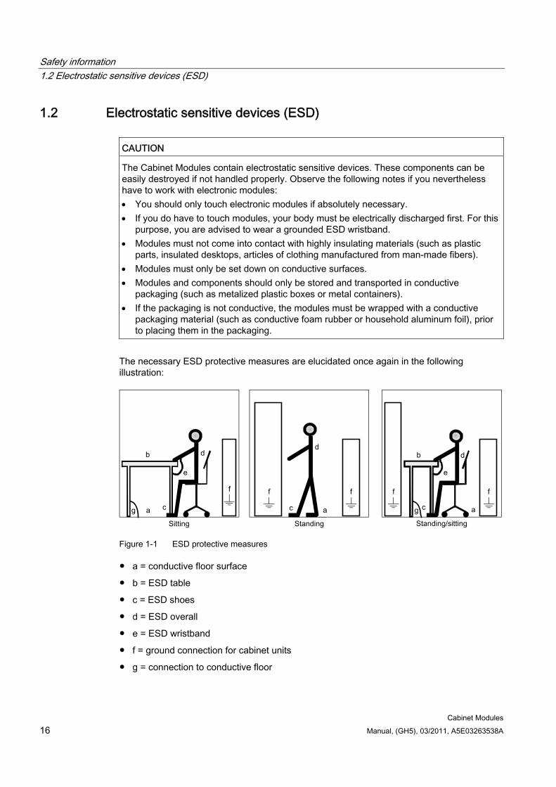
The necessary ESD protective measures are elucidated once again in the following illustration:
g g a
b
e
d
c
d
a c
d b
c a
e
f f f f f
Figure 1-1 ESD protective measures
a = conductive floor surface
b = ESD table
c = ESD shoes
d = ESD overall
e = ESD wristband
f = ground connection for cabinet units
g = connection to conductive floor
Safety information 1.3 Safety information
Cabinet Modules Manual, (GH5), 03/2011, A5E03263538A 17
1.3 Safety information
DANGER SINAMICS S120 Cabinet Modules must only be commissioned by suitably qualified personnel.
The personnel must take into account the information provided in the technical customer documentation for the product, and be familiar with and observe the specified danger and warning notices.
Operational electrical equipment and motors have parts and components which are at hazardous voltage levels.
Dangerous motion of the driven machine components is possible when the system is operational.
All work on the electrical system must be carried out when the system has been disconnected from the power supply and is in a de-energized condition.
Note Machinery directive (2006/42/EC)
When the European common market was launched, a decision was made that the domestic Standards and regulations of all of the EU Member States relating to the technical implementation of machines would be harmonized. This meant that, as an internal market Directive, the content of the Machinery Directive had to be implemented by the individual member states as national legislation. For the Machinery Directive, this was realized with the aim of achieving standard protective goals and, in turn, removing technical trade barriers. In accordance with the definition of a machine ("an assembly of linked parts or components, at least one of which moves"), this Directive is extremely extensive. The revised version from 2006, which shall be binding as of Dec. 29, 2009 without transitional period, has expanded its area of application and now includes "Logic units to ensure safety functions".
The machinery directive involves the implementation of machines. It has 28 Articles and 12 Annexes. The basic safety and health requirements specified in Annex I of the Directive must be fulfilled for the safety of machines.
The protective goals must be implemented responsibly to ensure compliance with the Directive.
Manufacturers of a machine must verify that their machine complies with the basic requirements. This verification is facilitated by means of harmonized standards.
Safety information 1.3 Safety information
Cabinet Modules 18 Manual, (GH5), 03/2011, A5E03263538A
DANGER Five safety rules
When carrying out any kind of work on electrical devices, the following "five safety rules" must always be observed in accordance with EN 50110-1 and EN 50110-2: Disconnect from power supply. Protect against reconnection. Make sure that the equipment is de-energized. Ground and short-circuit. Cover or enclose adjacent components that are still live.
WARNING Safe, problem-free operation of SINAMICS S120 Cabinet Modules requires proper transportation, storage, setup, and installation, as well as careful operation and maintenance.
The details in the catalogs and proposals also apply to the design of special equipment versions.
In addition to the danger and warning information provided in the technical customer documentation, the applicable national, local, and plant-specific regulations and requirements must be taken into account.
Only protective extra-low voltages (PELV) that comply with EN 60204-1 may be connected to any connections and terminals that are intended for the voltage range between 0 V and 48 V.
CAUTION As part of routine tests, SINAMICS S120 Cabinet Modules undergo a voltage test in accordance with EN 61800-5-1. Prior to performing the voltage test for electrical equipment of industrial machines in accordance with EN 60204-1, Section 18.4, all connections of the Cabinet Modules must be disconnected/removed to prevent the units from being damaged.
Motors must be connected according to the circuit diagrams provided.
Note
When operated in dry operating areas, SINAMICS S120 Cabinet Modules with three-phase induction motors conform to Low Voltage Directive 2006/95/EC.
SINAMICS S120 Cabinet Modules with three-phase induction motors conform to EMC Directive 2004/108/EC in the configurations specified in the associated EC Declaration of Conformity, provided that the configuration guidelines and actions are consistently applied.
CAUTION Operating the equipment in the immediate vicinity (< 1.5 m) of mobile telephones with a transmitter power of > 1 W may lead to incorrect operation.
Safety information 1.4 Residual risks
Cabinet Modules Manual, (GH5), 03/2011, A5E03263538A 19
1.4 Residual risks
Residual risks of power drive systems When carrying out a risk assessment of the machine/plant in accordance with the EU Machinery Directive, the machine manufacturer/plant operator must consider the following residual risks associated with the control and drive components of a power drive system (PDS).
1. Unintentional movements of driven machine components during commissioning, operation, maintenance, and repairs caused by, for example:
– Hardware defects and/or software errors in the sensors, controllers, actuators, and connection technology
– Response times of the controller and drive
– Operating and/or ambient conditions not within the scope of the specification
– Parameterization, programming, cabling, and installation errors
– Use of radio devices / cellular phones in the immediate vicinity of the controller
– External influences / damage
2. Exceptional temperatures as well as emissions of light, noise, particles, or gas caused by, for example:
– Component malfunctions
– Software errors
– Operating and/or ambient conditions not within the scope of the specification
– External influences / damage
3. Hazardous shock voltages caused by, for example:
– Component malfunctions
– Influence of electrostatic charging
– Induction of voltages in moving motors
– Operating and/or ambient conditions not within the scope of the specification
– Condensation / conductive contamination
– External influences / damage
4. Electrical, magnetic and electromagnetic fields generated in operation that can pose a risk to people with a pacemaker, implants or metal replacement joints, etc. if they are too close.
5. Release of environmental pollutants or emissions as a result of improper operation of the system and/or failure to dispose of components safely and correctly.
For more information about residual risks of the Power Drive System components, see the relevant chapters in the technical user documentation.
Safety information 1.4 Residual risks
Cabinet Modules 20 Manual, (GH5), 03/2011, A5E03263538A
WARNING Electromagnetic fields "electro smog"
Electromagnetic fields are generated by the operation of electrical power engineering installations such as transformers, converters or motors.
Electromagnetic fields can interfere with electronic devices, which could cause them to malfunction. For example, the operation of pacemakers can be impaired, potentially leading to damage to a person's health or even death. It is therefore forbidden for persons with pacemakers to enter these areas.
The plant operator is responsible for taking appropriate measures (labels and hazard warnings) to adequately protect operating personnel and others against any possible risk. Observe the relevant nationally applicable health and safety regulations. In Germany,
"electromagnetic fields" are subject to regulations BGV B11 and BGR B11 stipulated by the German statutory industrial accident insurance institution.
Display adequate hazard warning notices.
Place barriers around hazardous areas. Take measures, e.g. using shields, to reduce electromagnetic fields at their source. Make sure that personnel are wearing the appropriate protective gear.
Cabinet Modules Manual, (GH5), 03/2011, A5E03263538A 21
System overview 22.1 Overview
SINAMICS S120 Cabinet Modules are the components of a modular cabinet unit system for multi-axis drives with a central supply infeed and a common DC link busbar, as typically found in paper-making machines, roller mills, test stands, or hoisting gear.
They contain built-in units from the SINAMICS S120 product series, thus making them an ideal supplement to the SINAMICS G150 and SINAMICS S150 series of cabinet units for single drives.
All drive components, from the supply infeed to the motor-side inverters, are configured in a clear, compact layout in the individual Cabinet Modules. They can be combined with great flexibility and can be optimally adapted to customer-specific requirements thanks to a comprehensive array of options.
The main components of the system are as follows:
Line Connection Modules with line-side components such as contactors, fuses, and circuit breakers, as well as line reactors for Basic Line Modules and Smart Line Modules.
Line Modules for the infeed in the following versions:
– Basic Line Modules for 2-quadrant operation
– Smart Line Modules for 4-quadrant operation
– Active Line Modules for 4-quadrant operation with negligible line harmonic distortions
Central Braking Modules for short-term braking
The following types of Motor Module:
– Booksize Cabinet Kits
– Chassis format
Auxiliary Power Supply Modules to supply the auxiliary power supply system
Control Units
Standardized interfaces for both the power and the control connections facilitate configuration and installation. Communication between the power modules and the central Control Unit takes place via DRIVE-CLiQ, the internal drive serial interface.
System overview 2.1 Overview
Cabinet Modules 22 Manual, (GH5), 03/2011, A5E03263538A
=~
M3~
=~
=~
=~
=~
=~
=~
=~
=~
=~
=~
M3~
M3~
M3~
M3~
M3~
M3~
M3~
M3~
M3~
M3~
M3~
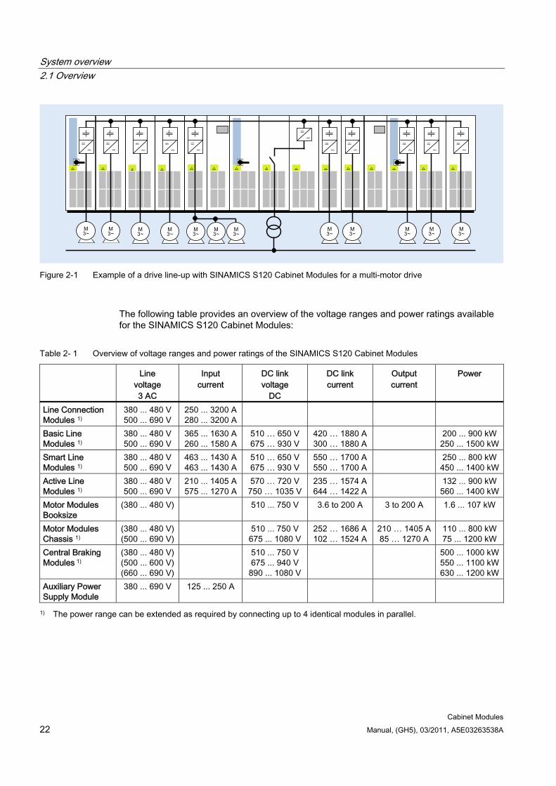
Figure 2-1 Example of a drive line-up with SINAMICS S120 Cabinet Modules for a multi-motor drive
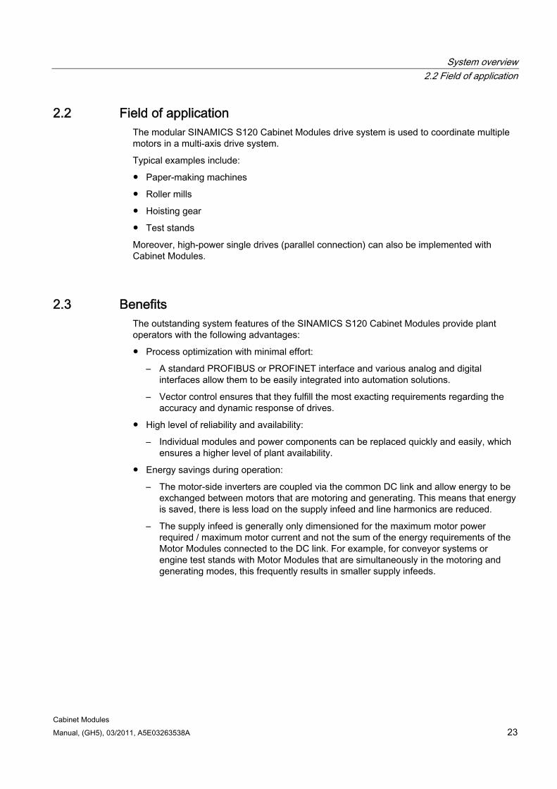
The following table provides an overview of the voltage ranges and power ratings available for the SINAMICS S120 Cabinet Modules:
Table 2- 1 Overview of voltage ranges and power ratings of the SINAMICS S120 Cabinet Modules
Line voltage 3 AC
Input current
DC link voltage
DC
DC link current
Output current
Power
Line Connection Modules 1)
380 ... 480 V500 ... 690 V
250 ... 3200 A280 ... 3200 A
Basic Line Modules 1)
380 ... 480 V500 ... 690 V
365 ... 1630 A260 ... 1580 A
510 … 650 V675 … 930 V
420 … 1880 A300 … 1880 A
200 ... 900 kW250 ... 1500 kW
Smart Line Modules 1)
380 ... 480 V500 ... 690 V
463 ... 1430 A463 ... 1430 A
510 … 650 V675 … 930 V
550 … 1700 A550 … 1700 A
250 ... 800 kW450 ... 1400 kW
Active Line Modules 1)
380 ... 480 V500 ... 690 V
210 ... 1405 A575 ... 1270 A
570 … 720 V750 … 1035 V
235 … 1574 A644 … 1422 A
132 ... 900 kW560 ... 1400 kW
Motor Modules Booksize
(380 ... 480 V) 510 ... 750 V 3.6 to 200 A 3 to 200 A 1.6 ... 107 kW
Motor Modules Chassis 1)
(380 ... 480 V) (500 ... 690 V)
510 ... 750 V 675 ... 1080 V
252 … 1686 A102 … 1524 A
210 … 1405 A 85 … 1270 A
110 ... 800 kW75 ... 1200 kW
Central Braking Modules 1)
(380 ... 480 V) (500 ... 600 V) (660 ... 690 V)
510 ... 750 V 675 ... 940 V
890 ... 1080 V
500 ... 1000 kW550 ... 1100 kW630 ... 1200 kW
Auxiliary Power Supply Module
380 ... 690 V 125 ... 250 A
1) The power range can be extended as required by connecting up to 4 identical modules in parallel.
System overview 2.2 Field of application
Cabinet Modules Manual, (GH5), 03/2011, A5E03263538A 23
2.2 Field of application The modular SINAMICS S120 Cabinet Modules drive system is used to coordinate multiple motors in a multi-axis drive system.
Typical examples include:
Paper-making machines
Roller mills
Hoisting gear
Test stands
Moreover, high-power single drives (parallel connection) can also be implemented with Cabinet Modules.
2.3 Benefits The outstanding system features of the SINAMICS S120 Cabinet Modules provide plant operators with the following advantages:
Process optimization with minimal effort:
– A standard PROFIBUS or PROFINET interface and various analog and digital interfaces allow them to be easily integrated into automation solutions.
– Vector control ensures that they fulfill the most exacting requirements regarding the accuracy and dynamic response of drives.
High level of reliability and availability:
– Individual modules and power components can be replaced quickly and easily, which ensures a higher level of plant availability.
Energy savings during operation:
– The motor-side inverters are coupled via the common DC link and allow energy to be exchanged between motors that are motoring and generating. This means that energy is saved, there is less load on the supply infeed and line harmonics are reduced.
– The supply infeed is generally only dimensioned for the maximum motor power required / maximum motor current and not the sum of the energy requirements of the Motor Modules connected to the DC link. For example, for conveyor systems or engine test stands with Motor Modules that are simultaneously in the motoring and generating modes, this frequently results in smaller supply infeeds.
System overview 2.4 Line Modules
Cabinet Modules 24 Manual, (GH5), 03/2011, A5E03263538A
Cost minimization during operation, maintenance, and service:
– Simple commissioning thanks to the menu-driven "STARTER" commissioning tool.
– Optional menu-prompted AOP30 advanced operator panel for clear and user-friendly drive monitoring / diagnostics, commissioning, and operation using a user-friendly, backlit graphic LCD for plain-text display and a bar-type display of process variables.
– All device modules are easily accessible, which makes them extremely service friendly.
Space-saving design
Environmentally-friendly operation:
– The converters are exceptionally quiet and compact thanks to state-of-the-art IGBT power semiconductors and an innovative cooling concept.
2.4 Line Modules
2.4.1 General information Power is fed to the drive line-up via Line Modules, which generate a DC voltage from the line voltage and, therefore, supply energy to the Motor Modules connected to the DC link. They are suitable for connection to systems grounded at the neutral point (TN, TT) and non-grounded (IT) systems.
The Line Modules are connected to the incoming supply via Line Connection Modules and are implemented in accordance with EN 61800-3 Category C3.
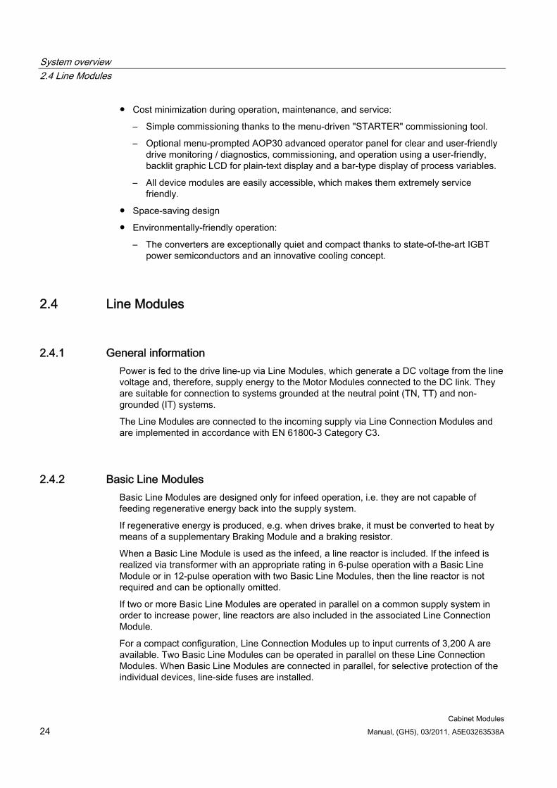
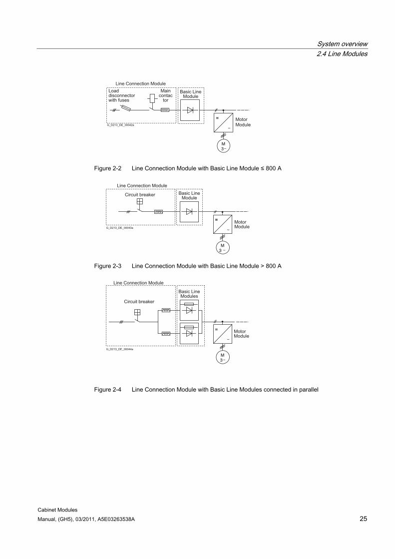
2.4.2 Basic Line Modules Basic Line Modules are designed only for infeed operation, i.e. they are not capable of feeding regenerative energy back into the supply system.
If regenerative energy is produced, e.g. when drives brake, it must be converted to heat by means of a supplementary Braking Module and a braking resistor.
When a Basic Line Module is used as the infeed, a line reactor is included. If the infeed is realized via transformer with an appropriate rating in 6-pulse operation with a Basic Line Module or in 12-pulse operation with two Basic Line Modules, then the line reactor is not required and can be optionally omitted.
If two or more Basic Line Modules are operated in parallel on a common supply system in order to increase power, line reactors are also included in the associated Line Connection Module.
For a compact configuration, Line Connection Modules up to input currents of 3,200 A are available. Two Basic Line Modules can be operated in parallel on these Line Connection Modules. When Basic Line Modules are connected in parallel, for selective protection of the individual devices, line-side fuses are installed.
System overview 2.4 Line Modules
Cabinet Modules Manual, (GH5), 03/2011, A5E03263538A 25
M3
=
Maincontac
tor
Load disconnector with fuses
G_D213_DE_00042a
=
Basic LineModule
MotorModule
Line Connection Module
Figure 2-2 Line Connection Module with Basic Line Module ≤ 800 A
M3
=
Circuit breaker
G_D213_DE_00043a
= MotorModule
Basic LineModule
Line Connection Module
Figure 2-3 Line Connection Module with Basic Line Module > 800 A
M3
=
Circuit breaker
G_D213_DE_00044a
= MotorModule
Basic LineModules
Line Connection Module
Figure 2-4 Line Connection Module with Basic Line Modules connected in parallel

System overview 2.4 Line Modules
Cabinet Modules 26 Manual, (GH5), 03/2011, A5E03263538A
2.4.3 Smart Line Modules Smart Line Modules can supply energy to the DC link and return regenerative energy to the supply system. A Braking Module and braking resistor are required only if the drives need to be decelerated in a controlled manner after a power failure (i.e. when energy cannot be recovered to the supply). When a Smart Line Module is used as the infeed, the corresponding line reactor is a standard requirement.
For a compact configuration, Line Connection Modules up to input currents of 3,200 A are available. Two Smart Line Modules can be operated in parallel on these Line Connection Modules.
M3
=
Smart LineModule
Maincontactor
Load disconnector
with fuses
G_D213_DE_00045a
Linereactor
Line Connection Module
Smart LineModule
MotorModule
Figure 2-5 Line Connection Module with Smart Line Module ≤ 800 A
M3
LinereactorCircuit breaker
MotorModule
Smart LineModule
=
Line Connection Module
Figure 2-6 Line Connection Module with Smart Line Module > 800 A
M3
Smart LineModule
Circuit breaker
Linereactor
MotorModule
Line Connection Module
=
Figure 2-7 Line Connection Module with Smart Line Modules connected in parallel
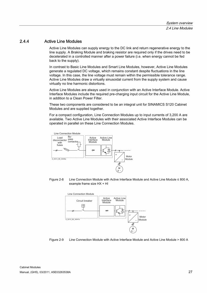
System overview 2.4 Line Modules
Cabinet Modules Manual, (GH5), 03/2011, A5E03263538A 27
2.4.4 Active Line Modules Active Line Modules can supply energy to the DC link and return regenerative energy to the line supply. A Braking Module and braking resistor are required only if the drives need to be decelerated in a controlled manner after a power failure (i.e. when energy cannot be fed back to the supply).
In contrast to Basic Line Modules and Smart Line Modules, however, Active Line Modules generate a regulated DC voltage, which remains constant despite fluctuations in the line voltage. In this case, the line voltage must remain within the permissible tolerance range. Active Line Modules draw a virtually sinusoidal current from the supply system and cause virtually no line harmonic distortions.
Active Line Modules are always used in conjunction with an Active Interface Module. Active Interface Modules include the required pre-charging input circuit for the Active Line Module, in addition to a Clean Power Filter.
These two components are considered to be an integral unit for SINAMICS S120 Cabinet Modules and are supplied together.
For a compact configuration, Line Connection Modules up to input currents of 3,200 A are available. Two Active Line Modules with their associated Active Interface Modules can be operated in parallel on these Line Connection Modules.
M3
By- passcontactor
Load disconnector
with fuses
G_D213_DE_00046a
=Motor
Module
Line Connection Module
Active LineModule
ActiveInterfaceModule
Figure 2-8 Line Connection Module with Active Interface Module and Active Line Module ≤ 800 A,
example frame size HX + HI
M3
Circuit breaker
G_D213_DE_00047a
= MotorModule
Line Connection Module
Active LineModule
ActiveInterfaceModule
Figure 2-9 Line Connection Module with Active Interface Module and Active Line Module > 800 A
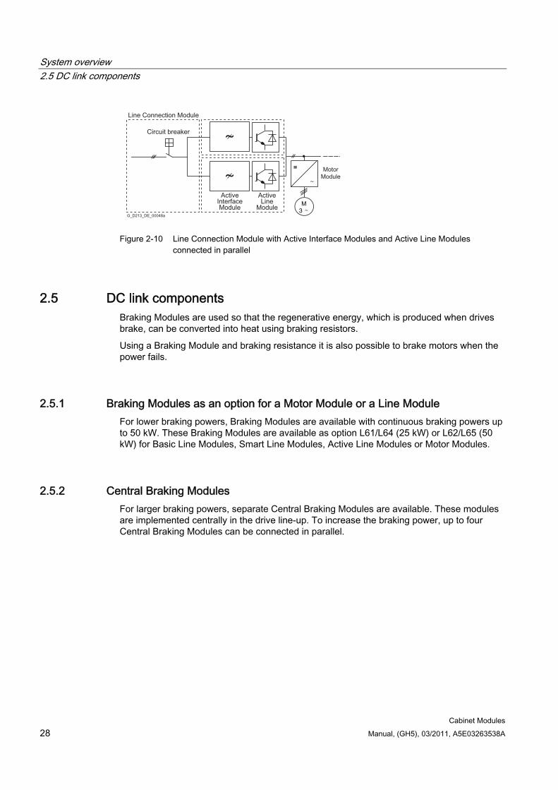
System overview 2.5 DC link components
Cabinet Modules 28 Manual, (GH5), 03/2011, A5E03263538A
M3
=
Circuit breaker
G_D213_DE_00048a
= MotorModule
Active InterfaceModule
Active Line
Module
Line Connection Module
Figure 2-10 Line Connection Module with Active Interface Modules and Active Line Modules
connected in parallel
2.5 DC link components Braking Modules are used so that the regenerative energy, which is produced when drives brake, can be converted into heat using braking resistors.
Using a Braking Module and braking resistance it is also possible to brake motors when the power fails.
2.5.1 Braking Modules as an option for a Motor Module or a Line Module For lower braking powers, Braking Modules are available with continuous braking powers up to 50 kW. These Braking Modules are available as option L61/L64 (25 kW) or L62/L65 (50 kW) for Basic Line Modules, Smart Line Modules, Active Line Modules or Motor Modules.
2.5.2 Central Braking Modules For larger braking powers, separate Central Braking Modules are available. These modules are implemented centrally in the drive line-up. To increase the braking power, up to four Central Braking Modules can be connected in parallel.
System overview 2.6 Motor Modules
Cabinet Modules Manual, (GH5), 03/2011, A5E03263538A 29
2.6 Motor Modules There are two different types of Motor Module available with the SINAMICS S120 Cabinet Modules drive system.
2.6.1 Booksize Base Cabinets with Booksize Cabinet Kits Motor Modules at the low end of the power range (1.6 to 107 kW) can be configured as Booksize Cabinet Kits installed in Booksize Base Cabinets. Booksize Cabinet Kits are also available as Double Motor Modules in the 1.6 to 9.7 kW power range.
2.6.2 Chassis Cabinets Each Chassis Cabinet is fitted with one SINAMICS S120 Motor Module in chassis format and covers the 75 to 1200 kW power range.
Higher powers can be achieved by connecting the Motor Modules in parallel.
2.7 Auxiliary Power Supply Modules Auxiliary Power Supply Modules supply power to the auxiliary power supply system of the SINAMICS S120 Cabinet Modules.
The fans of the SINAMICS S120 devices installed in the Cabinet Modules are some of the devices connected to this auxiliary power supply system. In addition, the auxiliary power supply system supplies the electronics modules with external 24 V DC. This is required when the DC link is not charged in order, for example, to maintain PROFIBUS communication.
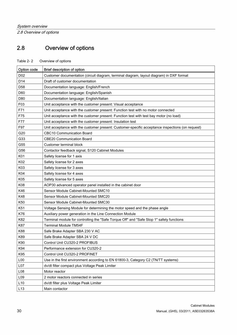
System overview 2.8 Overview of options
Cabinet Modules 30 Manual, (GH5), 03/2011, A5E03263538A
2.8 Overview of options
Table 2- 2 Overview of options
Option code Brief description of option D02 Customer documentation (circuit diagram, terminal diagram, layout diagram) in DXF format D14 Draft of customer documentation D58 Documentation language: English/French D60 Documentation language: English/Spanish D80 Documentation language: English/Italian F03 Unit acceptance with the customer present: Visual acceptance F71 Unit acceptance with the customer present: Function test with no motor connected F75 Unit acceptance with the customer present: Function test with test bay motor (no load) F77 Unit acceptance with the customer present: Insulation test F97 Unit acceptance with the customer present: Customer-specific acceptance inspections (on request) G20 CBC10 Communication Board G33 CBE20 Communication Board G55 Customer terminal block G56 Contactor feedback signal, S120 Cabinet Modules K01 Safety license for 1 axis K02 Safety license for 2 axes K03 Safety license for 3 axes K04 Safety license for 4 axes K05 Safety license for 5 axes K08 AOP30 advanced operator panel installed in the cabinet door K46 Sensor Module Cabinet-Mounted SMC10 K48 Sensor Module Cabinet-Mounted SMC20 K50 Sensor Module Cabinet-Mounted SMC30 K51 Voltage Sensing Module for determining the motor speed and the phase angle K76 Auxiliary power generation in the Line Connection Module K82 Terminal module for controlling the "Safe Torque Off" and "Safe Stop 1" safety functions K87 Terminal Module TM54F K88 Safe Brake Adapter SBA 230 V AC K89 Safe Brake Adapter SBA 24 V DC K90 Control Unit CU320-2 PROFIBUS K94 Performance extension for CU320-2 K95 Control Unit CU320-2 PROFINET L00 Use in the first environment according to EN 61800-3, Category C2 (TN/TT systems) L07 dv/dt filter compact plus Voltage Peak Limiter L08 Motor reactor L09 2 motor reactors connected in series L10 dv/dt filter plus Voltage Peak Limiter L13 Main contactor
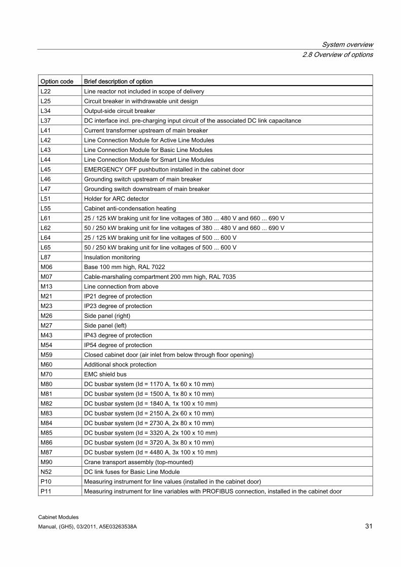
System overview 2.8 Overview of options
Cabinet Modules Manual, (GH5), 03/2011, A5E03263538A 31
Option code Brief description of option L22 Line reactor not included in scope of delivery L25 Circuit breaker in withdrawable unit design L34 Output-side circuit breaker L37 DC interface incl. pre-charging input circuit of the associated DC link capacitance L41 Current transformer upstream of main breaker L42 Line Connection Module for Active Line Modules L43 Line Connection Module for Basic Line Modules L44 Line Connection Module for Smart Line Modules L45 EMERGENCY OFF pushbutton installed in the cabinet door L46 Grounding switch upstream of main breaker L47 Grounding switch downstream of main breaker L51 Holder for ARC detector L55 Cabinet anti-condensation heating L61 25 / 125 kW braking unit for line voltages of 380 ... 480 V and 660 ... 690 V L62 50 / 250 kW braking unit for line voltages of 380 ... 480 V and 660 ... 690 V L64 25 / 125 kW braking unit for line voltages of 500 ... 600 V L65 50 / 250 kW braking unit for line voltages of 500 ... 600 V L87 Insulation monitoring M06 Base 100 mm high, RAL 7022 M07 Cable-marshaling compartment 200 mm high, RAL 7035 M13 Line connection from above M21 IP21 degree of protection M23 IP23 degree of protection M26 Side panel (right) M27 Side panel (left) M43 IP43 degree of protection M54 IP54 degree of protection M59 Closed cabinet door (air inlet from below through floor opening) M60 Additional shock protection M70 EMC shield bus M80 DC busbar system (Id = 1170 A, 1x 60 x 10 mm) M81 DC busbar system (Id = 1500 A, 1x 80 x 10 mm) M82 DC busbar system (Id = 1840 A, 1x 100 x 10 mm) M83 DC busbar system (Id = 2150 A, 2x 60 x 10 mm) M84 DC busbar system (Id = 2730 A, 2x 80 x 10 mm) M85 DC busbar system (Id = 3320 A, 2x 100 x 10 mm) M86 DC busbar system (Id = 3720 A, 3x 80 x 10 mm) M87 DC busbar system (Id = 4480 A, 3x 100 x 10 mm) M90 Crane transport assembly (top-mounted) N52 DC link fuses for Basic Line Module P10 Measuring instrument for line values (installed in the cabinet door) P11 Measuring instrument for line variables with PROFIBUS connection, installed in the cabinet door
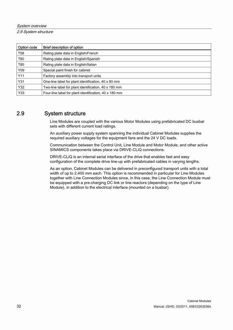
System overview 2.9 System structure
Cabinet Modules 32 Manual, (GH5), 03/2011, A5E03263538A
Option code Brief description of option T58 Rating plate data in English/French T60 Rating plate data in English/Spanish T80 Rating plate data in English/Italian Y09 Special paint finish for cabinet Y11 Factory assembly into transport units Y31 One-line label for plant identification, 40 x 80 mm Y32 Two-line label for plant identification, 40 x 180 mm Y33 Four-line label for plant identification, 40 x 180 mm
2.9 System structure Line Modules are coupled with the various Motor Modules using prefabricated DC busbar sets with different current load ratings.
An auxiliary power supply system spanning the individual Cabinet Modules supplies the required auxiliary voltages for the equipment fans and the 24 V DC loads.
Communication between the Control Unit, Line Module and Motor Module, and other active SINAMICS components takes place via DRIVE-CLiQ connections.
DRIVE-CLiQ is an internal serial interface of the drive that enables fast and easy configuration of the complete drive line-up with prefabricated cables in varying lengths.
As an option, Cabinet Modules can be delivered in preconfigured transport units with a total width of up to 2,400 mm each. This option is recommended in particular for Line Modules together with Line Connection Modules since, in this case, the Line Connection Module must be equipped with a pre-charging DC link or line reactors (depending on the type of Line Module), in addition to the electrical interface (mounted on a busbar).
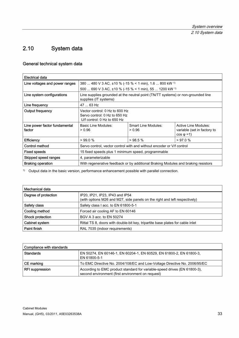
System overview 2.10 System data
Cabinet Modules Manual, (GH5), 03/2011, A5E03263538A 33
2.10 System data
General technical system data Electrical data Line voltages and power ranges 380 ... 480 V 3 AC, ±10 % (-15 % < 1 min), 1.6 ... 800 kW 1)
500 ... 690 V 3 AC, ±10 % (-15 % < 1 min), 55 ... 1200 kW 1) Line system configurations Line supplies grounded at the neutral point (TN/TT systems) or non-grounded line
supplies (IT systems) Line frequency 47 ... 63 Hz Output frequency Vector control: 0 Hz to 600 Hz
Servo control: 0 Hz to 650 Hz U/f control: 0 Hz to 650 Hz
Line power factor fundamental factor
Basic Line Modules: > 0.96
Smart Line Modules: > 0.96
Active Line Modules: variable (set in factory to cos φ =1)
Efficiency > 99.0 % > 98.5 % > 97.0 % Control method Servo control, vector control with and without encoder or V/f control Fixed speeds 15 fixed speeds plus 1 minimum speed, programmable Skipped speed ranges 4, parameterizable Braking operation With regenerative feedback or by additional Braking Modules and braking resistors
1) Output data in the basic version, performance enhancement possible with parallel connection.
Mechanical data Degree of protection IP20, IP21, IP23, IP43 and IP54
(with options M26 and M27, side panels on the right and left respectively) Safety class Safety class I acc. to EN 61800-5-1 Cooling method Forced air cooling AF to EN 60146 Shock protection BGV A 3 acc. to EN 50274 Cabinet system Rittal TS 8, doors with double-bit key, tripartite base plates for cable inlet Paint finish RAL 7035 (indoor requirements)
Compliance with standards Standards EN 50274, EN 60146-1, EN 60204-1, EN 60529, EN 61800-2, EN 61800-3,
EN 61800-5-1 CE marking To EMC Directive No. 2004/108/EC and Low-Voltage Directive No. 2006/95/EC RFI suppression According to EMC product standard for variable-speed drives (EN 61800-3),
second environment (first environment on request)
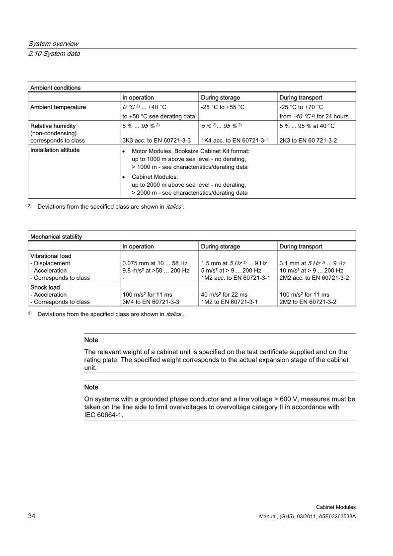
System overview 2.10 System data
Cabinet Modules 34 Manual, (GH5), 03/2011, A5E03263538A
Ambient conditions In operation During storage During transport Ambient temperature 0 °C 2) ... +40 °C
to +50 °C see derating data -25 °C to +55 °C -25 °C to +70 °C
from -40 °C 2) for 24 hours Relative humidity (non-condensing) corresponds to class
5 % ... 95 % 2) 3K3 acc. to EN 60721-3-3
5 % 2)... 95 % 2) 1K4 acc. to EN 60721-3-1
5 % ... 95 % at 40 °C 2K3 to EN 60 721-3-2
Installation altitude Motor Modules, Booksize Cabinet Kit format: up to 1000 m above sea level - no derating, > 1000 m - see characteristics/derating data
Cabinet Modules: up to 2000 m above sea level - no derating, > 2000 m - see characteristics/derating data
2) Deviations from the specified class are shown in italics .
Mechanical stability In operation During storage During transport Vibrational load - Displacement - Acceleration - Corresponds to class
0.075 mm at 10 ... 58 Hz 9.8 m/s² at >58 ... 200 Hz -
1.5 mm at 5 Hz 3) ... 9 Hz 5 m/s² at > 9 ... 200 Hz 1M2 acc. to EN 60721-3-1
3.1 mm at 5 Hz 3) ... 9 Hz 10 m/s² at > 9 ... 200 Hz 2M2 acc. to EN 60721-3-2
Shock load - Acceleration - Corresponds to class
100 m/s2 for 11 ms 3M4 to EN 60721-3-3
40 m/s2 for 22 ms 1M2 to EN 60721-3-1
100 m/s2 for 11 ms 2M2 to EN 60721-3-2
3) Deviations from the specified class are shown in italics .
Note
The relevant weight of a cabinet unit is specified on the test certificate supplied and on the rating plate. The specified weight corresponds to the actual expansion stage of the cabinet unit.
Note
On systems with a grounded phase conductor and a line voltage > 600 V, measures must be taken on the line side to limit overvoltages to overvoltage category II in accordance with IEC 60664-1.
System overview 2.11 Derating data
Cabinet Modules Manual, (GH5), 03/2011, A5E03263538A 35
2.11 Derating data
2.11.1 Derating data for booksize format SINAMICS S120 Cabinet Modules with power units, booksize format, and the associated system components are dimensioned for an ambient temperature of 40 °C and installation altitudes up to 1000 m above sea level. If SINAMICS S120 Cabinet Modules with power units in the booksize format are operated at ambient temperatures higher than 40 °C and/or installation altitudes higher than 1000 m above sea level, then the corresponding derating factors must be taken into account as a function of the ambient temperature and/or the installation altitude. These derating factors differ from the derating factors for chassis format power units and are specified in Catalog PM21 / SINAMICS S120 Drive System. They are valid for SINAMICS S120 Cabinet Modules with booksize format power units in degrees of protection IP20, IP21, IP23, IP43 and IP54.
2.11.2 Derating data for chassis format
2.11.2.1 General SINAMICS S120 Cabinet Modules as well as the associated system components are dimensioned for an ambient temperature of 40 °C and installation altitudes up to 2000 m above sea level.
S120 Cabinet Modules include Basic Line Modules, Smart Line Modules, Active Line Modules and Motor Modules with power units, chassis format including the associated system components, (e.g. line filter, chassis Braking Modules and motor filter), as well as Line Connection Modules and Auxiliary Power Supply Modules.
Exceptions are S120 Cabinet Modules with power units, Booksize format and the Central Braking Modules. This derating data can be taken from Chapter "Cabinet Modules" in subchapter "Derating data" of the particular S120 Cabinet Modules.
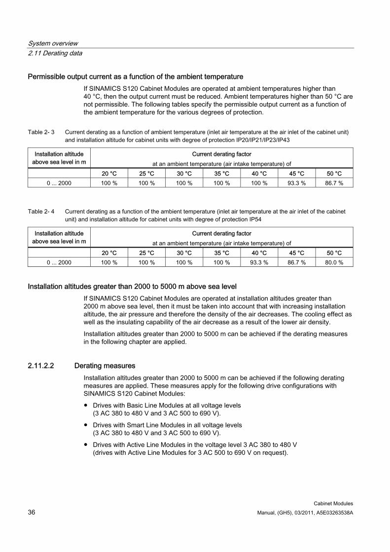
System overview 2.11 Derating data
Cabinet Modules 36 Manual, (GH5), 03/2011, A5E03263538A
Permissible output current as a function of the ambient temperature If SINAMICS S120 Cabinet Modules are operated at ambient temperatures higher than 40 °C, then the output current must be reduced. Ambient temperatures higher than 50 °C are not permissible. The following tables specify the permissible output current as a function of the ambient temperature for the various degrees of protection.
Table 2- 3 Current derating as a function of ambient temperature (inlet air temperature at the air inlet of the cabinet unit) and installation altitude for cabinet units with degree of protection IP20/IP21/IP23/IP43
Installation altitude above sea level in m
Current derating factor at an ambient temperature (air intake temperature) of
20 °C 25 °C 30 °C 35 °C 40 °C 45 °C 50 °C 0 ... 2000 100 % 100 % 100 % 100 % 100 % 93.3 % 86.7 %
Table 2- 4 Current derating as a function of the ambient temperature (inlet air temperature at the air inlet of the cabinet unit) and installation altitude for cabinet units with degree of protection IP54
Installation altitude above sea level in m
Current derating factor at an ambient temperature (air intake temperature) of
20 °C 25 °C 30 °C 35 °C 40 °C 45 °C 50 °C 0 ... 2000 100 % 100 % 100 % 100 % 93.3 % 86.7 % 80.0 %
Installation altitudes greater than 2000 to 5000 m above sea level If SINAMICS S120 Cabinet Modules are operated at installation altitudes greater than 2000 m above sea level, then it must be taken into account that with increasing installation altitude, the air pressure and therefore the density of the air decreases. The cooling effect as well as the insulating capability of the air decrease as a result of the lower air density.
Installation altitudes greater than 2000 to 5000 m can be achieved if the derating measures in the following chapter are applied.
2.11.2.2 Derating measures Installation altitudes greater than 2000 to 5000 m can be achieved if the following derating measures are applied. These measures apply for the following drive configurations with SINAMICS S120 Cabinet Modules:
Drives with Basic Line Modules at all voltage levels (3 AC 380 to 480 V and 3 AC 500 to 690 V).
Drives with Smart Line Modules in all voltage levels (3 AC 380 to 480 V and 3 AC 500 to 690 V).
Drives with Active Line Modules in the voltage level 3 AC 380 to 480 V (drives with Active Line Modules for 3 AC 500 to 690 V on request).
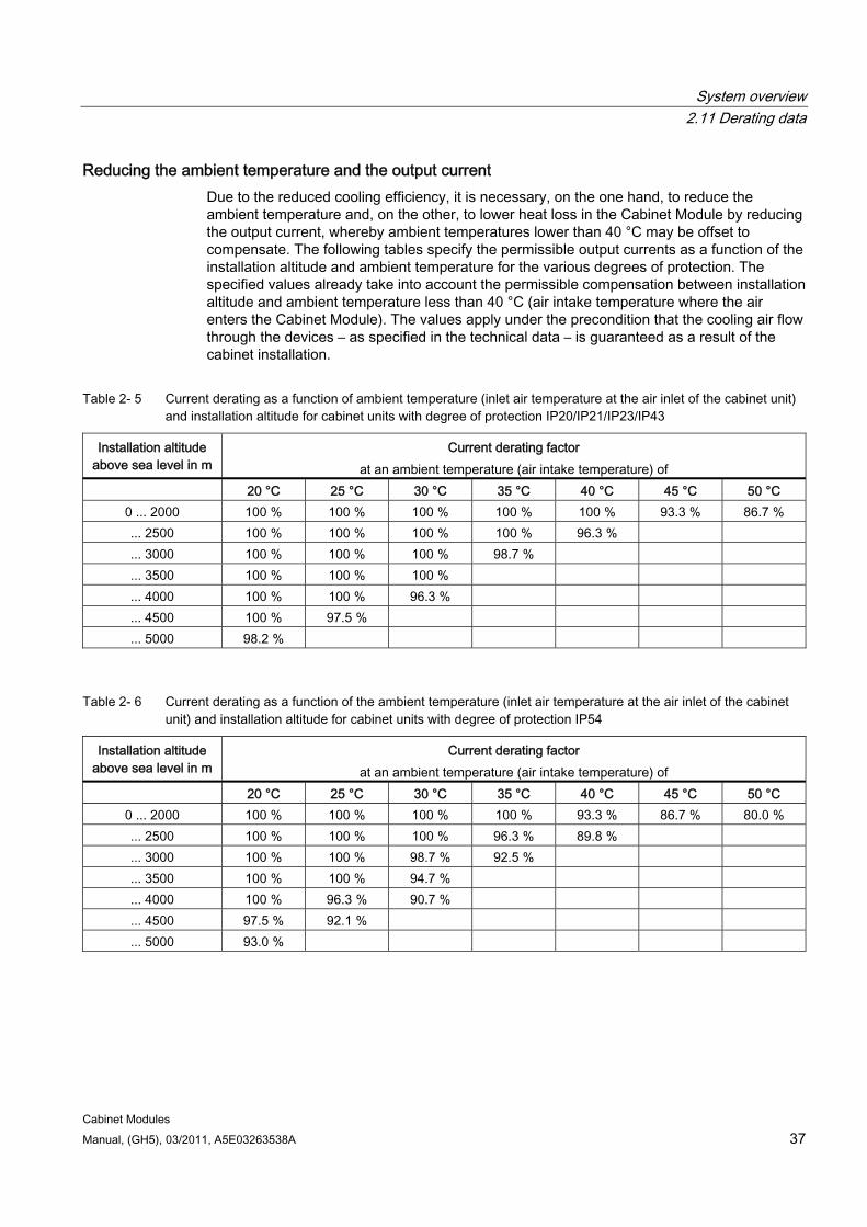
System overview 2.11 Derating data
Cabinet Modules Manual, (GH5), 03/2011, A5E03263538A 37
Reducing the ambient temperature and the output current Due to the reduced cooling efficiency, it is necessary, on the one hand, to reduce the ambient temperature and, on the other, to lower heat loss in the Cabinet Module by reducing the output current, whereby ambient temperatures lower than 40 °C may be offset to compensate. The following tables specify the permissible output currents as a function of the installation altitude and ambient temperature for the various degrees of protection. The specified values already take into account the permissible compensation between installation altitude and ambient temperature less than 40 °C (air intake temperature where the air enters the Cabinet Module). The values apply under the precondition that the cooling air flow through the devices – as specified in the technical data – is guaranteed as a result of the cabinet installation.
Table 2- 5 Current derating as a function of ambient temperature (inlet air temperature at the air inlet of the cabinet unit) and installation altitude for cabinet units with degree of protection IP20/IP21/IP23/IP43
Installation altitude above sea level in m
Current derating factor at an ambient temperature (air intake temperature) of
20 °C 25 °C 30 °C 35 °C 40 °C 45 °C 50 °C 0 ... 2000 100 % 100 % 100 % 100 % 100 % 93.3 % 86.7 % ... 2500 100 % 100 % 100 % 100 % 96.3 % ... 3000 100 % 100 % 100 % 98.7 % ... 3500 100 % 100 % 100 % ... 4000 100 % 100 % 96.3 % ... 4500 100 % 97.5 % ... 5000 98.2 %
Table 2- 6 Current derating as a function of the ambient temperature (inlet air temperature at the air inlet of the cabinet unit) and installation altitude for cabinet units with degree of protection IP54
Installation altitude above sea level in m
Current derating factor at an ambient temperature (air intake temperature) of
20 °C 25 °C 30 °C 35 °C 40 °C 45 °C 50 °C 0 ... 2000 100 % 100 % 100 % 100 % 93.3 % 86.7 % 80.0 % ... 2500 100 % 100 % 100 % 96.3 % 89.8 % ... 3000 100 % 100 % 98.7 % 92.5 % ... 3500 100 % 100 % 94.7 % ... 4000 100 % 96.3 % 90.7 % ... 4500 97.5 % 92.1 % ... 5000 93.0 %
System overview 2.11 Derating data
Cabinet Modules 38 Manual, (GH5), 03/2011, A5E03263538A
Use of an isolating transformer to reduce transient overvoltages according to IEC 61800-5-1 As a consequence, overvoltage category III is reduced to overvoltage category II – which in turn reduces the demands placed on the insulating capability of air. An additional voltage derating (reduction of the input voltage) is not required if the following secondary conditions are maintained:
The isolation transformer must be fed from a low-voltage supply or a medium-voltage supply and must not be directly supplied from a high voltage supply.
The isolation transformer may supply one or several Line Modules.
The cables between the isolation transformer and the Line Module or Line Modules must be routed so that a direct lightning strike is completely ruled out, i.e. cables must not be routed outside.
The following line supply types are permissible for drives equipped with Basic Line Modules and Smart Line Modules:
– TN line supplies with grounded star point (no grounded phase conductor).
– IT line supplies (operation with a short circuit must be restricted to the absolutely shortest possible time).
The following line supply types are permissible for drives equipped with Active Line Modules:
– TN systems with grounded star point (no grounded outer conductor, no IT systems) for installation altitudes of greater than 2000 m.
Cabinet Modules Manual, (GH5), 03/2011, A5E03263538A 39
Mechanical installation 33.1 Important notes
Transport
WARNING Please note the following when transporting the cabinet units: The devices are heavy and are usually top heavy. The center of gravity is marked on the
devices. Ensure that the ground at the installation location is strong enough to bear the weight of
the cabinet units. Suitable hoisting gear operated by trained personnel is also required due to the weight
of the cabinet units. The cabinet units must always be transported in the upright position indicated. The
cabinet units must not be tipped and transported in a horizontal position. Transport units comprise several cabinet units. Due to their weight and length, transport
units must only be transported with the transport rails mounted on top and the wooden pallets attached.
Serious injury or even death and substantial material damage can occur if the cabinet units are not lifted or transported properly.
Note
Notes on transportation: The cabinet units are packaged by the manufacturer in accordance with the climatic
conditions and stresses encountered during transit and in the recipient country. The notes on the packaging relating to transportation, storage, and proper handling must
be observed. The cabinet units must be carried on a wooden pallet when transported with fork-lift
trucks. NOTICE:
Cabinet units must not be disassembled while still on wooden pallets and awaiting transport.
If required, cabinet units can be delivered in transport units. When a crane is used to move the cabinet units, a crane transport assembly is provided for the transport unit.
Permissible ambient temperatures during transport: – -25 °C to +70 °C Class 2K3 to EN 60721-3-2 – briefly up to -40 °C for max. 24 hours
Mechanical installation 3.1 Important notes
Cabinet Modules 40 Manual, (GH5), 03/2011, A5E03263538A
Note
Notes regarding damage in transit: Carry out a thorough visual inspection of the SINAMICS S120 Cabinet Modules before
accepting the delivery from the shipping company. Pay special attention to transport damage that is not readily apparent but indicated by the tilt and shock indicators.
Check that you have received all the items specified on the delivery note. Notify the shipping company immediately of any missing components or damage. If you identify any hidden defects or damage, contact the shipping company immediately
and ask them to examine the cabinet. If you fail to contact them immediately, you may lose your right to claim compensation for
the defects and damage. If necessary, you can request the support of your local Siemens office.
WARNING
Damage in transit indicates that the cabinet was subject to unreasonable stress. The electrical safety of the cabinet can no longer be ensured. It must not be connected until a thorough high-voltage test has been carried out.
Death, serious injury, or substantial material damage can result if these factors are not taken into account.
WARNING Inform Technical Support (hotline)
Commissioning must not be carried out, if an indicator has tripped. Please contact Technical Support immediately.
If commissioning is carried out without prior inspection of the indicators, safe operation of the converter cannot be guaranteed. This can result in death, serious personal injury or material damage.
Mechanical installation 3.1 Important notes
Cabinet Modules Manual, (GH5), 03/2011, A5E03263538A 41
Storage The cabinet units must be stored in clean, dry rooms. Temperatures between -25 °C and +55 °C are permissible (class 1K4 to EN 60721-3-1). Temperature variations greater than 20 K per hour are not permitted.
If the cabinets are stored for a prolonged period, cover them or take other appropriate measures to ensure that they do not become dirty and that they are protected against environmental influences. If such measures are not taken, the warranty becomes invalid in the event of a claim for damages.
WARNING The cabinet unit should not be stored for more than two years. If the cabinet unit is stored for more than two years, the DC link capacitors of the power units must be reformed during commissioning.
The reforming procedure is described in the chapter titled "Maintenance and service", section "Reforming the DC link capacitors".
CAUTION Do not apply mechanical loads to the hoods!
The hoods (option M23, M43 or M54) are delivered separately and must be installed on site.
Therefore the hoods must not be subjected to mechanical loads, otherwise they could be destroyed.
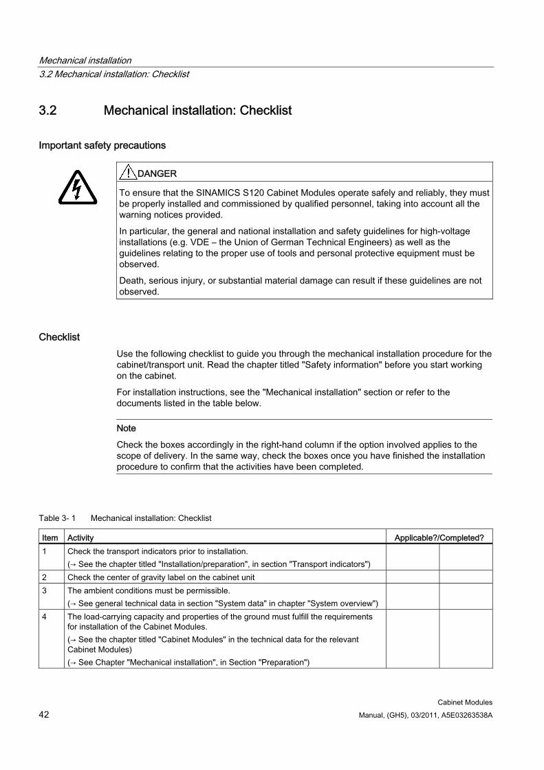
Mechanical installation 3.2 Mechanical installation: Checklist
Cabinet Modules 42 Manual, (GH5), 03/2011, A5E03263538A
3.2 Mechanical installation: Checklist
Important safety precautions
DANGER
To ensure that the SINAMICS S120 Cabinet Modules operate safely and reliably, they must be properly installed and commissioned by qualified personnel, taking into account all the warning notices provided.
In particular, the general and national installation and safety guidelines for high-voltage installations (e.g. VDE – the Union of German Technical Engineers) as well as the guidelines relating to the proper use of tools and personal protective equipment must be observed.
Death, serious injury, or substantial material damage can result if these guidelines are not observed.
Checklist Use the following checklist to guide you through the mechanical installation procedure for the cabinet/transport unit. Read the chapter titled "Safety information" before you start working on the cabinet.
For installation instructions, see the "Mechanical installation" section or refer to the documents listed in the table below.
Note
Check the boxes accordingly in the right-hand column if the option involved applies to the scope of delivery. In the same way, check the boxes once you have finished the installation procedure to confirm that the activities have been completed.
Table 3- 1 Mechanical installation: Checklist
Item Activity Applicable?/Completed? 1 Check the transport indicators prior to installation.
(→ See the chapter titled "Installation/preparation", in section "Transport indicators")
2 Check the center of gravity label on the cabinet unit 3 The ambient conditions must be permissible.
(→ See general technical data in section "System data" in chapter "System overview")
4 The load-carrying capacity and properties of the ground must fulfill the requirements for installation of the Cabinet Modules. (→ See the chapter titled "Cabinet Modules" in the technical data for the relevant Cabinet Modules) (→ See Chapter "Mechanical installation", in Section "Preparation")
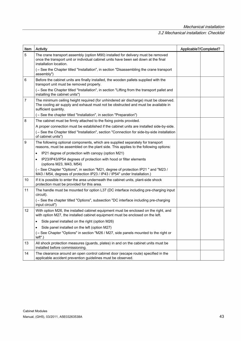
Mechanical installation 3.2 Mechanical installation: Checklist
Cabinet Modules Manual, (GH5), 03/2011, A5E03263538A 43
Item Activity Applicable?/Completed? 5 The crane transport assembly (option M90) installed for delivery must be removed
once the transport unit or individual cabinet units have been set down at the final installation location. (→ See the Chapter titled "Installation", in section "Disassembling the crane transport assembly")
6 Before the cabinet units are finally installed, the wooden pallets supplied with the transport unit must be removed properly. (→ See the Chapter titled "Installation", in section "Lifting from the transport pallet and installing the cabinet units")
7 The minimum ceiling height required (for unhindered air discharge) must be observed. The cooling air supply and exhaust must not be obstructed and must be available in sufficient quantity. (→ See the chapter titled "Installation", in section "Preparation")
8 The cabinet must be firmly attached to the fixing points provided. A proper connection must be established if the cabinet units are installed side-by-side. (→ See the Chapter titled "Installation", section "Connection for side-by-side installation of cabinet units")
9 The following optional components, which are supplied separately for transport reasons, must be assembled on the plant side. This applies to the following options: IP21 degree of protection with canopy (option M21) IP23/IP43/IP54 degrees of protection with hood or filter elements
(options M23, M43, M54) (→ See Chapter "Options", in section "M21, degree of protection IP21 " and "M23 / M43 / M54, degrees of protection IP23 / IP43 / IP54" under Installation.)
10 If it is possible to enter the area underneath the cabinet units, plant-side shock protection must be provided for this area.
11 The handle must be mounted for option L37 (DC interface including pre-charging input circuit). (→ See the chapter titled "Options", subsection "DC interface including pre-charging input circuit")
12 With option M26, the installed cabinet equipment must be enclosed on the right, and with option M27, the installed cabinet equipment must be enclosed on the left. Side panel installed on the right (option M26) Side panel installed on the left (option M27) (→ See Chapter "Options" in section "M26 / M27, side panels mounted to the right or left".)
13 All shock protection measures (guards, plates) in and on the cabinet units must be installed before commissioning.
14 The clearance around an open control cabinet door (escape route) specified in the applicable accident prevention guidelines must be observed.
Mechanical installation 3.3 Installation
Cabinet Modules 44 Manual, (GH5), 03/2011, A5E03263538A
3.3 Installation
3.3.1 Important safety precautions
DANGER
To ensure that the cabinet units operate safely and reliably, they must be properly installed and commissioned by qualified personnel, taking into account all the warning notices provided.
In particular, the general and national installation and safety guidelines for high-voltage installations (e.g. VDE – the Union of German Technical Engineers) as well as the guidelines relating to the proper use of tools and personal protective equipment must be observed.
Death, serious injury, or substantial material damage can result if these guidelines are not observed.
3.3.2 Preparatory steps
3.3.2.1 On-site requirements The Cabinet Modules are designed for installation in closed, electrical operating areas in compliance with EN 61800-5-1. A closed electrical operating area is a room or area containing electrical equipment which can be accessed by trained personnel only. Access is controlled by a door or other form of barricade which can be opened only by means of a key or other tool. The room or area is also clearly signed with appropriate warning notices.
The installation location must be dry and dust-free. The air supplied must not contain any electrically conductive gas, vapors, or dust, which could impair operation. It may be necessary to filter the air supplied to the installation room. If the air contains dust, filter mats (option M54) can be installed in front of the ventilation grilles in the cabinet doors and also in front of the hoods, if necessary. Option M54 offers additional protection against water sprayed against the housing from any direction and corresponds to degree of protection IP54.
The permissible values for climatic ambient conditions must be taken into account.
Derating is required for ambient temperatures > 40 °C (104 °F) and installation altitudes > 1000 m (Booksize Cabinet Kit) or > 2000 m (Chassis) (→ see Chapter "System overview" under Derating data).
The basic version of the cabinet units complies with the IP20 degree of protection in accordance with EN 60529.
CAUTION Cabinet Modules do not fulfill the requirements for IP20 until they have been closed off by installing a side panel on the right (option M26) and a side panel on the left (option M27).
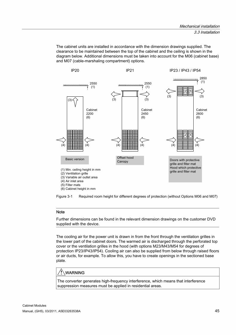
Mechanical installation 3.3 Installation
Cabinet Modules Manual, (GH5), 03/2011, A5E03263538A 45
The cabinet units are installed in accordance with the dimension drawings supplied. The clearance to be maintained between the top of the cabinet and the ceiling is shown in the diagram below. Additional dimensions must be taken into account for the M06 (cabinet base) and M07 (cable-marshaling compartment) options.
Figure 3-1 Required room height for different degrees of protection (without Options M06 and M07)
Note
Further dimensions can be found in the relevant dimension drawings on the customer DVD supplied with the device.
The cooling air for the power unit is drawn in from the front through the ventilation grilles in the lower part of the cabinet doors. The warmed air is discharged through the perforated top cover or the ventilation grilles in the hood (with options M23/M43/M54 for degrees of protection IP23/IP43/IP54). Cooling air can also be supplied from below through raised floors or air ducts, for example. To allow this, you have to create openings in the sectioned base plate.
WARNING The converter generates high-frequency interference, which means that interference suppression measures must be applied in residential areas.
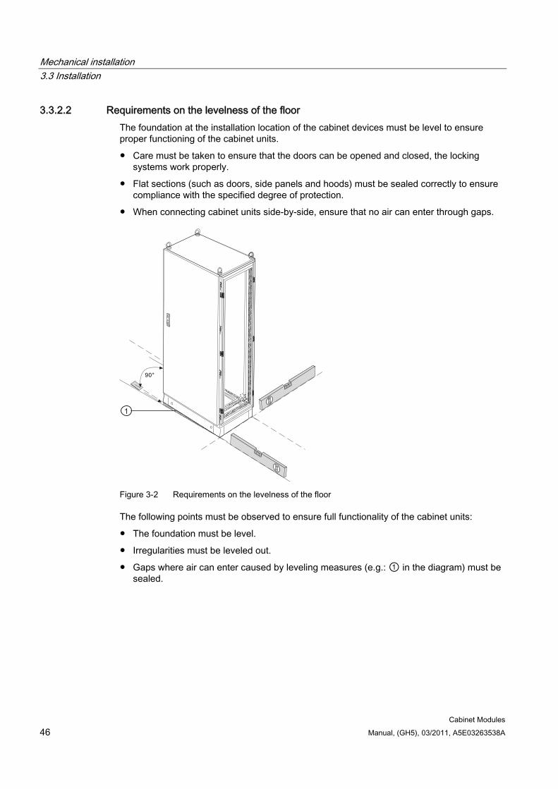
Mechanical installation 3.3 Installation
Cabinet Modules 46 Manual, (GH5), 03/2011, A5E03263538A
3.3.2.2 Requirements on the levelness of the floor The foundation at the installation location of the cabinet devices must be level to ensure proper functioning of the cabinet units.
Care must be taken to ensure that the doors can be opened and closed, the locking systems work properly.
Flat sections (such as doors, side panels and hoods) must be sealed correctly to ensure compliance with the specified degree of protection.
When connecting cabinet units side-by-side, ensure that no air can enter through gaps.
Figure 3-2 Requirements on the levelness of the floor
The following points must be observed to ensure full functionality of the cabinet units:
The foundation must be level.
Irregularities must be leveled out.
Gaps where air can enter caused by leveling measures (e.g.: ① in the diagram) must be sealed.
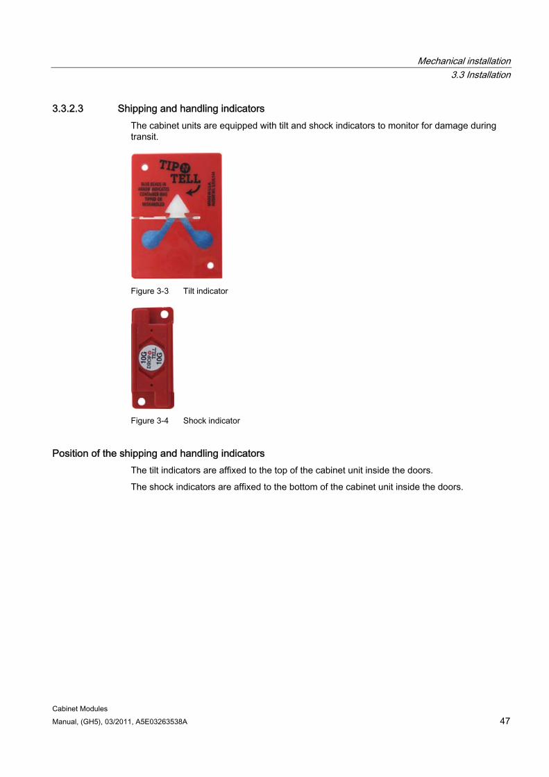
Mechanical installation 3.3 Installation
Cabinet Modules Manual, (GH5), 03/2011, A5E03263538A 47
3.3.2.3 Shipping and handling indicators The cabinet units are equipped with tilt and shock indicators to monitor for damage during transit.
Figure 3-3 Tilt indicator
Figure 3-4 Shock indicator
Position of the shipping and handling indicators The tilt indicators are affixed to the top of the cabinet unit inside the doors.
The shock indicators are affixed to the bottom of the cabinet unit inside the doors.
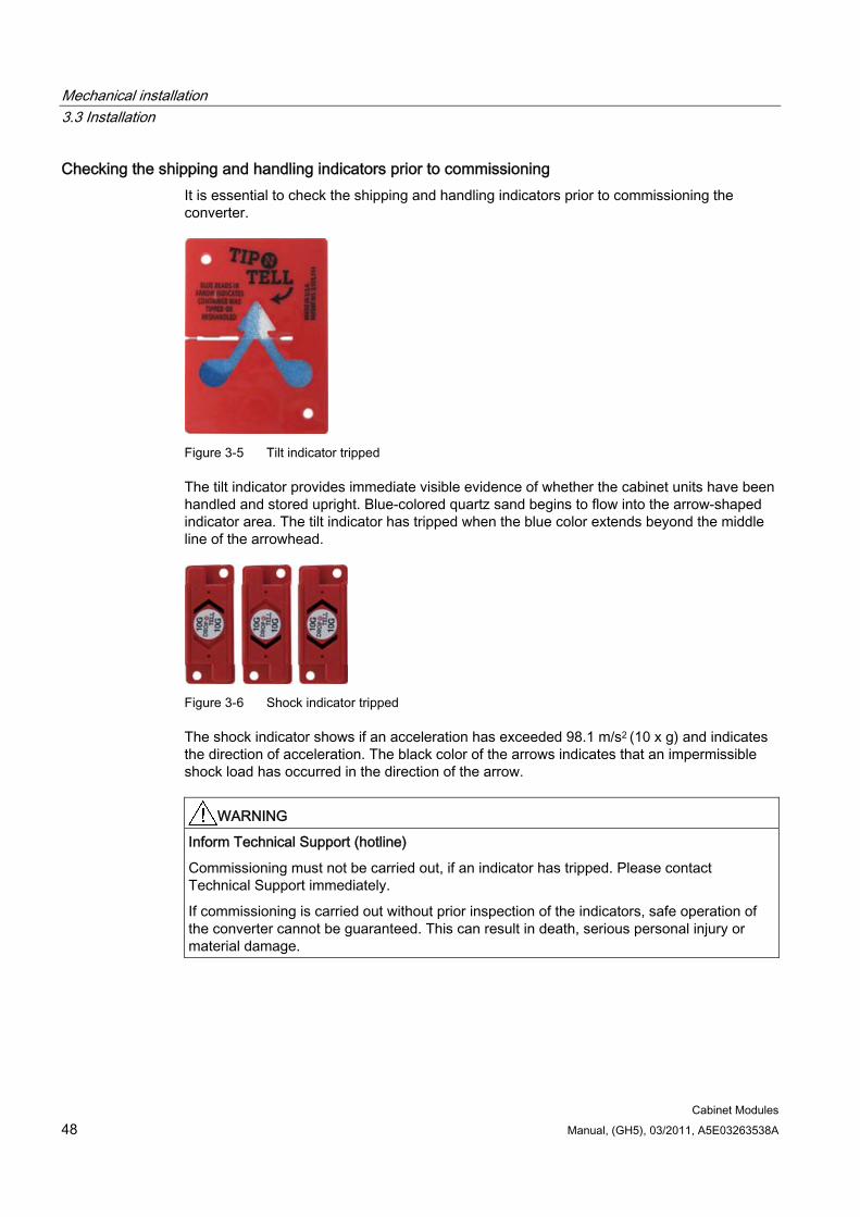
Mechanical installation 3.3 Installation
Cabinet Modules 48 Manual, (GH5), 03/2011, A5E03263538A
Checking the shipping and handling indicators prior to commissioning It is essential to check the shipping and handling indicators prior to commissioning the converter.
Figure 3-5 Tilt indicator tripped
The tilt indicator provides immediate visible evidence of whether the cabinet units have been handled and stored upright. Blue-colored quartz sand begins to flow into the arrow-shaped indicator area. The tilt indicator has tripped when the blue color extends beyond the middle line of the arrowhead.
Figure 3-6 Shock indicator tripped
The shock indicator shows if an acceleration has exceeded 98.1 m/s2 (10 x g) and indicates the direction of acceleration. The black color of the arrows indicates that an impermissible shock load has occurred in the direction of the arrow.
WARNING Inform Technical Support (hotline)
Commissioning must not be carried out, if an indicator has tripped. Please contact Technical Support immediately.
If commissioning is carried out without prior inspection of the indicators, safe operation of the converter cannot be guaranteed. This can result in death, serious personal injury or material damage.
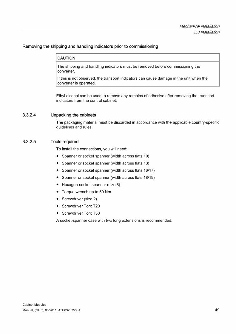
Mechanical installation 3.3 Installation
Cabinet Modules Manual, (GH5), 03/2011, A5E03263538A 49
Removing the shipping and handling indicators prior to commissioning
CAUTION The shipping and handling indicators must be removed before commissioning the converter.
If this is not observed, the transport indicators can cause damage in the unit when the converter is operated.
Ethyl alcohol can be used to remove any remains of adhesive after removing the transport indicators from the control cabinet.
3.3.2.4 Unpacking the cabinets The packaging material must be discarded in accordance with the applicable country-specific guidelines and rules.
3.3.2.5 Tools required To install the connections, you will need:
Spanner or socket spanner (width across flats 10)
Spanner or socket spanner (width across flats 13)
Spanner or socket spanner (width across flats 16/17)
Spanner or socket spanner (width across flats 18/19)
Hexagon-socket spanner (size 8)
Torque wrench up to 50 Nm
Screwdriver (size 2)
Screwdriver Torx T20
Screwdriver Torx T30
A socket-spanner case with two long extensions is recommended.
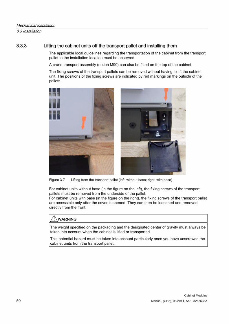
Mechanical installation 3.3 Installation
Cabinet Modules 50 Manual, (GH5), 03/2011, A5E03263538A
3.3.3 Lifting the cabinet units off the transport pallet and installing them The applicable local guidelines regarding the transportation of the cabinet from the transport pallet to the installation location must be observed.
A crane transport assembly (option M90) can also be fitted on the top of the cabinet.
The fixing screws of the transport pallets can be removed without having to lift the cabinet unit. The positions of the fixing screws are indicated by red markings on the outside of the pallets.
Figure 3-7 Lifting from the transport pallet (left: without base; right: with base)
For cabinet units without base (in the figure on the left), the fixing screws of the transport pallets must be removed from the underside of the pallet. For cabinet units with base (in the figure on the right), the fixing screws of the transport pallet are accessible only after the cover is opened. They can then be loosened and removed directly from the front.
WARNING The weight specified on the packaging and the designated center of gravity must always be taken into account when the cabinet is lifted or transported.
This potential hazard must be taken into account particularly once you have unscrewed the cabinet units from the transport pallet.
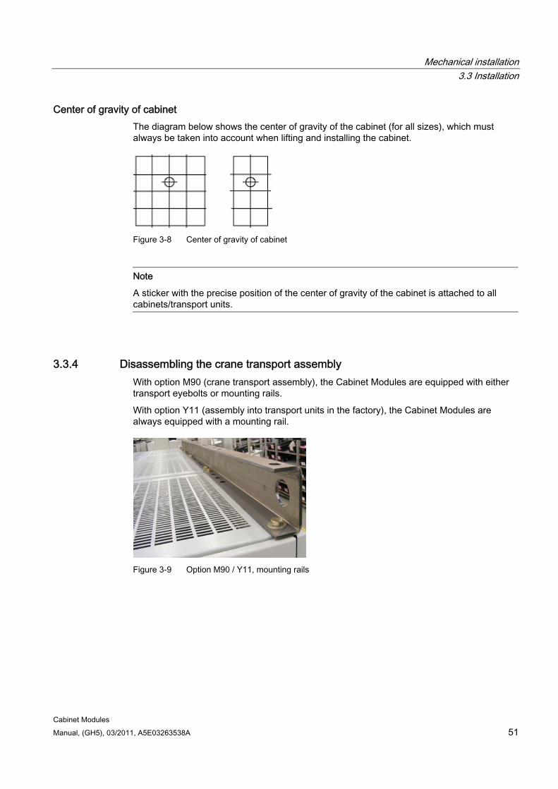
Mechanical installation 3.3 Installation
Cabinet Modules Manual, (GH5), 03/2011, A5E03263538A 51
Center of gravity of cabinet The diagram below shows the center of gravity of the cabinet (for all sizes), which must always be taken into account when lifting and installing the cabinet.
Figure 3-8 Center of gravity of cabinet
Note
A sticker with the precise position of the center of gravity of the cabinet is attached to all cabinets/transport units.
3.3.4 Disassembling the crane transport assembly With option M90 (crane transport assembly), the Cabinet Modules are equipped with either transport eyebolts or mounting rails.
With option Y11 (assembly into transport units in the factory), the Cabinet Modules are always equipped with a mounting rail.
Figure 3-9 Option M90 / Y11, mounting rails
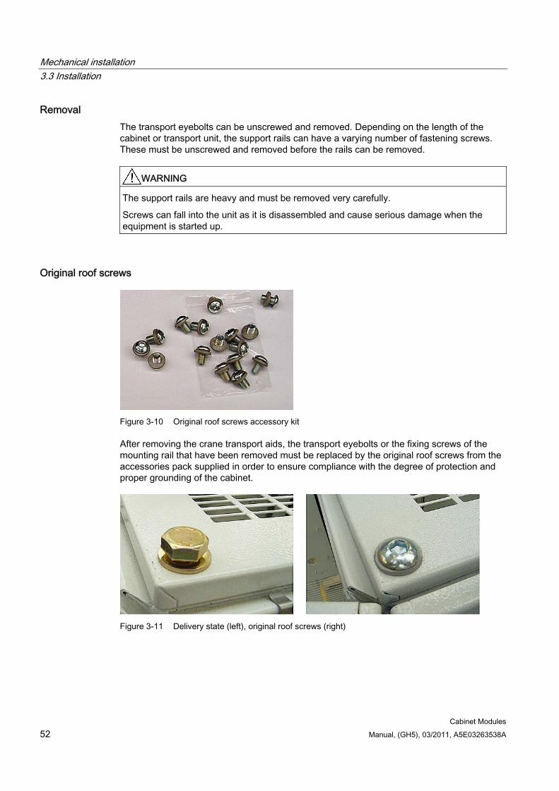
Mechanical installation 3.3 Installation
Cabinet Modules 52 Manual, (GH5), 03/2011, A5E03263538A
Removal The transport eyebolts can be unscrewed and removed. Depending on the length of the cabinet or transport unit, the support rails can have a varying number of fastening screws. These must be unscrewed and removed before the rails can be removed.
WARNING The support rails are heavy and must be removed very carefully.
Screws can fall into the unit as it is disassembled and cause serious damage when the equipment is started up.
Original roof screws
Figure 3-10 Original roof screws accessory kit
After removing the crane transport aids, the transport eyebolts or the fixing screws of the mounting rail that have been removed must be replaced by the original roof screws from the accessories pack supplied in order to ensure compliance with the degree of protection and proper grounding of the cabinet.
Figure 3-11 Delivery state (left), original roof screws (right)
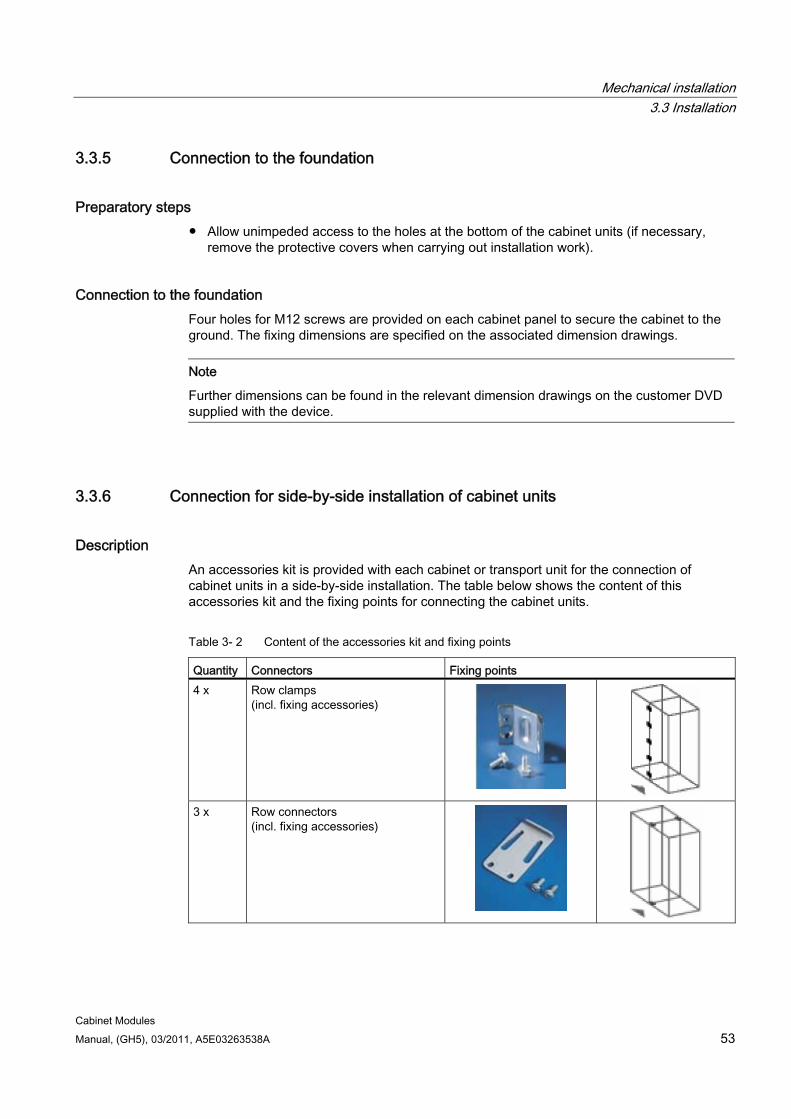
Mechanical installation 3.3 Installation
Cabinet Modules Manual, (GH5), 03/2011, A5E03263538A 53
3.3.5 Connection to the foundation
Preparatory steps Allow unimpeded access to the holes at the bottom of the cabinet units (if necessary,
remove the protective covers when carrying out installation work).
Connection to the foundation Four holes for M12 screws are provided on each cabinet panel to secure the cabinet to the ground. The fixing dimensions are specified on the associated dimension drawings.
Note
Further dimensions can be found in the relevant dimension drawings on the customer DVD supplied with the device.
3.3.6 Connection for side-by-side installation of cabinet units
Description An accessories kit is provided with each cabinet or transport unit for the connection of cabinet units in a side-by-side installation. The table below shows the content of this accessories kit and the fixing points for connecting the cabinet units.
Table 3- 2 Content of the accessories kit and fixing points
Quantity Connectors Fixing points 4 x Row clamps
(incl. fixing accessories)
3 x Row connectors
(incl. fixing accessories)
Mechanical installation 3.3 Installation
Cabinet Modules 54 Manual, (GH5), 03/2011, A5E03263538A
Preparatory steps Allow unimpeded access to the profiles in the cabinet interior (if necessary, remove the
side panels, doors, and protective covers).
Assembling 1. Attach the row clamps/row connectors to the appropriate profiles (as shown in the figures
above).
2. Insert and tighten the screws and washers.
3. If necessary, reattach the protective covers and doors.
Note Installing the canopy or hood at a an early stage!
It is recommended to attach the canopy or hood at an early stage to prevent foreign matter entering the cabinet units.
NOTICE Installing the side panels
For each row of cabinets installed, one side panel must be installed on the right (option M26) and one side panel on the left (option M27).
Cabinet Modules Manual, (GH5), 03/2011, A5E03263538A 55
Electrical installation 44.1 Safety information
Required safety precautions before installation work is carried out
DANGER The Cabinet Modules are used in industrial high-voltage installations. During operation, this Cabinet Module contains rotating and live parts. For this reason, there is a risk of severe injury or significant material damage if the required covers are removed without authorization, if it is used or operated incorrectly, or if it has not been properly maintained.
You must read and comply with the safety information provided in this Manual.
When carrying out any kind of work on electrical devices, the following five safety rules must always be observed in accordance with EN 50110-1 and EN 50110-2: Disconnect from power supply. Protect against reconnection. Make sure that the equipment is de-energized. Ground and short-circuit. Cover or enclose adjacent components that are still live.
Note
The Cabinet Modules come in a range of different frame sizes, with each size differing from the others in several ways. The main differences are: The covers used can have different dimensions, and they can be arranged and secured
in different ways. The components can be arranged differently within the cabinet units. The components can be mounted within the cabinet units using different methods.
These variations result from the different requirements made of the components/equipment installed in the cabinet units. These differences are intentional and exist for "EMC optimization" reasons.
Electrical installation 4.2 Electrical installation: Checklist
Cabinet Modules 56 Manual, (GH5), 03/2011, A5E03263538A
4.2 Electrical installation: Checklist
Important safety precautions
DANGER
The cabinet units are operated with high voltages. All connection work must be carried out when the cabinet is de-energized. All work on the unit must be carried out by trained personnel only.
Work on an open unit must be carried out with extreme caution because external supply voltages may be present. The power and control terminals may be live even when the motor is not running. Dangerously high voltage levels are still present in the unit up to 5 minutes after it has been disconnected due to the DC link capacitors. For this reason, the unit should not be opened until a reasonable period of time has elapsed.
The user is responsible for ensuring that the motor, cabinet units, and other components are installed and connected in accordance with the recognized technical rules in the country of installation and with other applicable regional regulations. Special attention should be paid to cable dimensioning, fuses, grounding, shutdown, disconnection, and overcurrent protection.
If an item of protective gear trips in a branch circuit, a leakage current may have been disconnected. To reduce the risk of fire or an electric shock, the current-carrying parts and other components in the cabinet should be inspected and damaged parts replaced. When an item of protective gear trips, the cause of the trip must be identified and rectified.
CAUTION Forming the DC link capacitors
The cabinet unit should not be stored for more than two years. If the device is stored for more than two years, its DC link capacitors must be reformed during commissioning. The reforming procedure is described in this Manual in the chapter titled "Maintenance and servicing", section "Reforming the DC link capacitors".
Checklist Use the checklist below to guide you through the electrical installation procedure for the cabinet. Read all the safety information in the section "Safety information" before carrying out any work on the unit.
For wiring instructions, see the "Electrical installation" section or refer to the documents listed in the table below.
Note
Check the boxes accordingly in the right-hand column if the option involved applies to the scope of delivery. In the same way, check the boxes once you have finished the installation procedure to confirm that the activities have been completed.
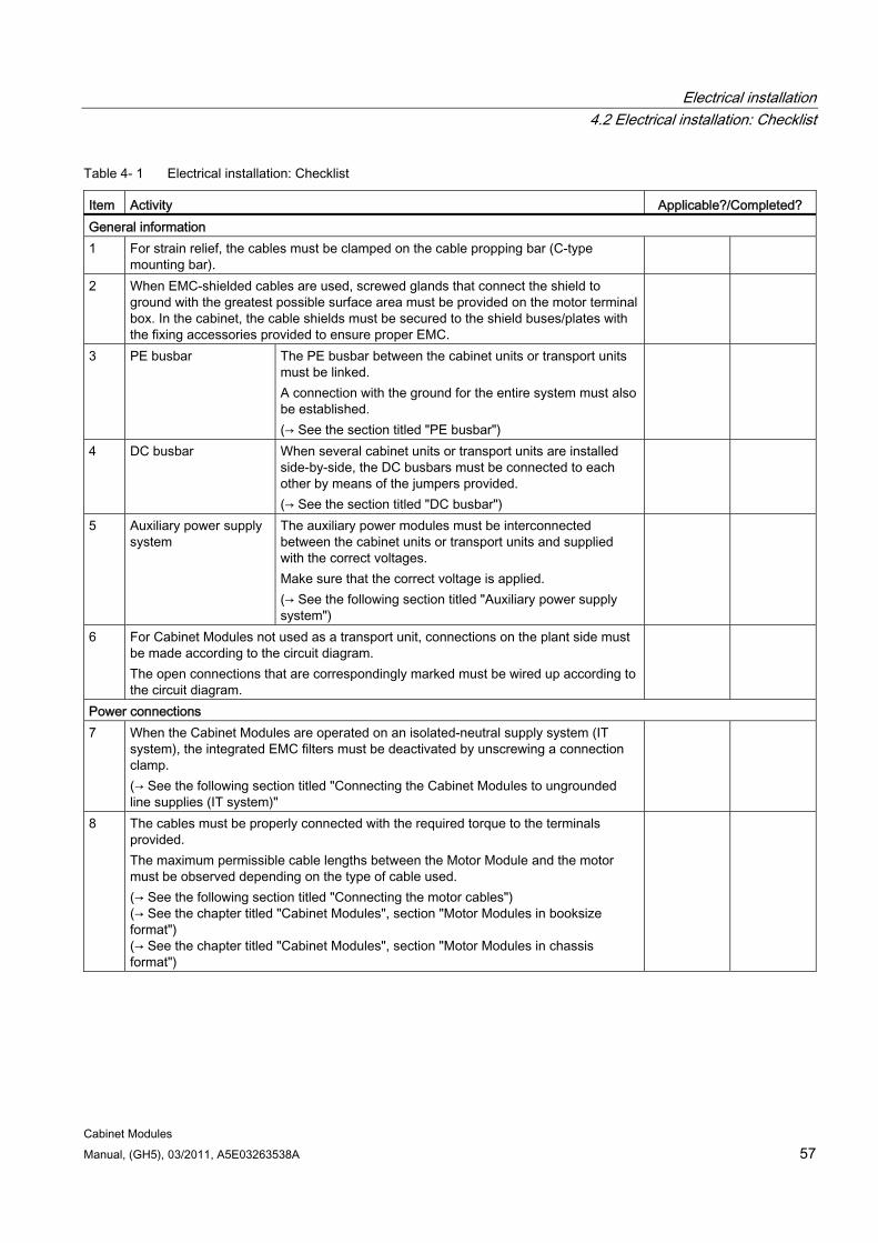
Electrical installation 4.2 Electrical installation: Checklist
Cabinet Modules Manual, (GH5), 03/2011, A5E03263538A 57
Table 4- 1 Electrical installation: Checklist
Item Activity Applicable?/Completed? General information 1 For strain relief, the cables must be clamped on the cable propping bar (C-type
mounting bar).
2 When EMC-shielded cables are used, screwed glands that connect the shield to ground with the greatest possible surface area must be provided on the motor terminal box. In the cabinet, the cable shields must be secured to the shield buses/plates with the fixing accessories provided to ensure proper EMC.
3 PE busbar The PE busbar between the cabinet units or transport units must be linked. A connection with the ground for the entire system must also be established. (→ See the section titled "PE busbar")
4 DC busbar When several cabinet units or transport units are installed side-by-side, the DC busbars must be connected to each other by means of the jumpers provided. (→ See the section titled "DC busbar")
5 Auxiliary power supply system
The auxiliary power modules must be interconnected between the cabinet units or transport units and supplied with the correct voltages. Make sure that the correct voltage is applied. (→ See the following section titled "Auxiliary power supply system")
6 For Cabinet Modules not used as a transport unit, connections on the plant side must be made according to the circuit diagram. The open connections that are correspondingly marked must be wired up according to the circuit diagram.
Power connections 7 When the Cabinet Modules are operated on an isolated-neutral supply system (IT
system), the integrated EMC filters must be deactivated by unscrewing a connection clamp. (→ See the following section titled "Connecting the Cabinet Modules to ungrounded line supplies (IT system)"
8 The cables must be properly connected with the required torque to the terminals provided. The maximum permissible cable lengths between the Motor Module and the motor must be observed depending on the type of cable used. (→ See the following section titled "Connecting the motor cables") (→ See the chapter titled "Cabinet Modules", section "Motor Modules in booksize format") (→ See the chapter titled "Cabinet Modules", section "Motor Modules in chassis format")
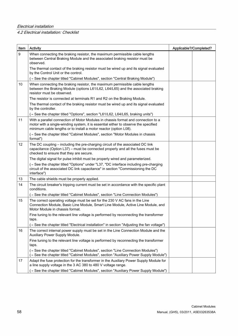
Electrical installation 4.2 Electrical installation: Checklist
Cabinet Modules 58 Manual, (GH5), 03/2011, A5E03263538A
Item Activity Applicable?/Completed? 9 When connecting the braking resistor, the maximum permissible cable lengths
between Central Braking Module and the associated braking resistor must be observed. The thermal contact of the braking resistor must be wired up and its signal evaluated by the Control Unit or the control. (→ See the chapter titled "Cabinet Modules", section "Central Braking Module")
10 When connecting the braking resistor, the maximum permissible cable lengths between the Braking Module (options L61/L62, L64/L65) and the associated braking resistor must be observed. The resistor is connected at terminals R1 and R2 on the Braking Module. The thermal contact of the braking resistor must be wired up and its signal evaluated by the controller. (→ See the chapter titled "Options", section "L61/L62, L64/L65, braking units")
11 With a parallel connection of Motor Modules in chassis format and connection to a motor with a single-winding system, it is essential either to observe the specified minimum cable lengths or to install a motor reactor (option L08). (→ See the chapter titled "Cabinet Modules", section "Motor Modules in chassis format")
12 The DC coupling – including the pre-charging circuit of the associated DC link capacitance (Option L37) – must be connected properly and all the fuses must be checked to ensure that they are secure. The digital signal for pulse inhibit must be properly wired and parameterized. (→ See the chapter titled "Options" under "L37, "DC interface including pre-charging circuit of the associated DC link capacitance" in section "Commissioning the DC interface")
13 The cable shields must be properly applied. 14 The circuit breaker's tripping current must be set in accordance with the specific plant
conditions. (→ See the chapter titled "Cabinet Modules", section "Line Connection Modules")
15 The correct operating voltage must be set for the 230 V AC fans in the Line Connection Module, Basic Line Module, Smart Line Module, Active Line Module, and Motor Module in chassis format. Fine tuning to the relevant line voltage is performed by reconnecting the transformer taps. (→ See the chapter titled "Electrical installation" in section "Adjusting the fan voltage")
16 The correct internal power supply must be set in the Line Connection Module and the Auxiliary Power Supply Module. Fine tuning to the relevant line voltage is performed by reconnecting the transformer taps. (→ See the chapter titled "Cabinet Modules", section "Line Connection Modules") (→ See the chapter titled "Cabinet Modules", section "Auxiliary Power Supply Module")
17 Adapt the fuse protection for the transformer in the Auxiliary Power Supply Module for a line supply voltage in the 3 AC 380 to 480 V voltage range. (→ See the chapter titled "Cabinet Modules", section "Auxiliary Power Supply Module")
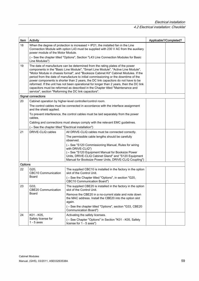
Electrical installation 4.2 Electrical installation: Checklist
Cabinet Modules Manual, (GH5), 03/2011, A5E03263538A 59
Item Activity Applicable?/Completed? 18 When the degree of protection is increased > IP21, the installed fan in the Line
Connection Module with option L43 must be supplied with 230 V AC from the auxiliary power module of the Motor Module. (→ See the chapter titled "Options", Section "L43 Line Connection Modules for Basic Line Modules")
19 The date of manufacture can be determined from the rating plates of the power components in the "Basic Line Module", "Smart Line Module", "Active Line Module", "Motor Module in chassis format", and "Booksize Cabinet Kit" Cabinet Modules. If the period from the date of manufacture to initial commissioning or the downtime of the power components is shorter than 2 years, the DC link capacitors do not have to be reformed. If the unit has not been operational for longer than 2 years, then the DC link capacitors must be reformed as described in the Chapter titled "Maintenance and service", section "Reforming the DC link capacitors".
Signal connections 20 Cabinet operation by higher-level controller/control room.
The control cables must be connected in accordance with the interface assignment and the shield applied. To prevent interference, the control cables must be laid separately from the power cables. Cabling and connections must always comply with the relevant EMC guidelines. (→ See the chapter titled "Electrical installation")
21 DRIVE-CLiQ cables All DRIVE-CLiQ cables must be connected correctly. The permissible cable lengths should be carefully observed. (→ See "S120 Commissioning Manual, Rules for wiring with DRIVE-CLiQ") (→ See "S120 Equipment Manual for Booksize Power Units, DRIVE-CLiQ Cabinet Gland" and "S120 Equipment Manual for Booksize Power Units, DRIVE-CLiQ Coupling")
Options 22 G20,
CBC10 Communication Board
The supplied CBC10 is installed in the factory in the option slot of the Control Unit. (→ See the Chapter titled "Options", in section "G20, CBC10 Communication Board")
23 G33, CBE20 Communication Board
The supplied CBE20 is installed in the factory in the option slot of the Control Unit. Remove the CBE20 in a no-current state and note down the MAC address. Install the CBE20 into the option slot again. (→ See the chapter titled "Options", section "G33, CBE20 Communication Board")
24 K01 - K05, Safety license for 1 - 5 axes
Activating the safety licenses. (→ See Chapter "Options" in Section "K01 - K05, Safety license for 1 - 5 axes")
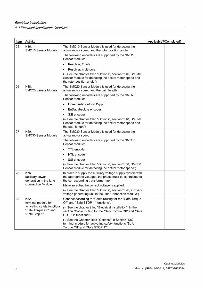
Electrical installation 4.2 Electrical installation: Checklist
Cabinet Modules 60 Manual, (GH5), 03/2011, A5E03263538A
Item Activity Applicable?/Completed? 25 K46,
SMC10 Sensor Module
The SMC10 Sensor Module is used for detecting the actual motor speed and the rotor position angle. The following encoders are supported by the SMC10 Sensor Module: Resolver, 2 pole Resolver, multi-pole (→ See the chapter titled "Options", section "K46, SMC10 Sensor Module for detecting the actual motor speed and the rotor position angle")
26 K48, SMC20 Sensor Module
The SMC20 Sensor Module is used for detecting the actual motor speed and the path length. The following encoders are supported by the SMC20 Sensor Module: Incremental sin/cos 1Vpp EnDat absolute encoder SSI encoder (→ See the chapter titled "Options", section "K48, SMC20 Sensor Module for detecting the actual motor speed and the path length")
27 K50, SMC30 Sensor Module
The SMC30 Sensor Module is used for detecting the actual motor speed. The following encoders are supported by the SMC30 Sensor Module: TTL encoder HTL encoder SSI encoder (→ See the chapter titled "Options", section "K50, SMC30 Sensor Module for detecting the actual motor speed")
28 K76, auxiliary power generation in the Line Connection Module
In order to supply the auxiliary voltage supply system with the appropriate voltages, the phase must be connected to the corresponding transformer tap. Make sure that the correct voltage is applied. (→ See the chapter titled "Options", section "K76, auxiliary voltage generating unit in the Line Connection Module")
29 K82, terminal module for activating safety functions "Safe Torque Off" and "Safe Stop 1"
Connect according to "Cable routing for the "Safe Torque Off" and "Safe STOP 1" functions". (→ See the chapter titled "Electrical installation", in the section "Cable routing for the "Safe Torque Off" and "Safe STOP 1" functions") (→ See the Chapter titled "Options", in Section "K82, terminal module for activating safety functions "Safe Torque Off" and "Safe STOP 1"")
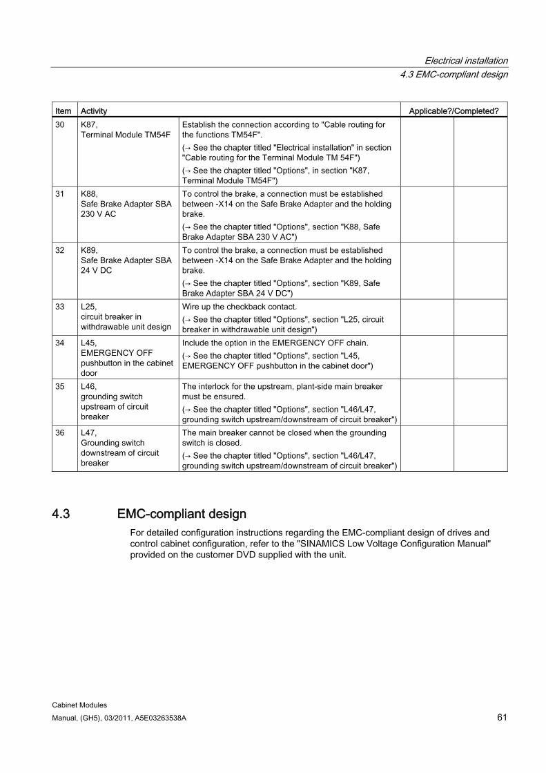
Electrical installation 4.3 EMC-compliant design
Cabinet Modules Manual, (GH5), 03/2011, A5E03263538A 61
Item Activity Applicable?/Completed? 30 K87,
Terminal Module TM54F Establish the connection according to "Cable routing for the functions TM54F". (→ See the chapter titled "Electrical installation" in section "Cable routing for the Terminal Module TM 54F") (→ See the chapter titled "Options", in section "K87, Terminal Module TM54F")
31 K88, Safe Brake Adapter SBA 230 V AC
To control the brake, a connection must be established between -X14 on the Safe Brake Adapter and the holding brake. (→ See the chapter titled "Options", section "K88, Safe Brake Adapter SBA 230 V AC")
32 K89, Safe Brake Adapter SBA 24 V DC
To control the brake, a connection must be established between -X14 on the Safe Brake Adapter and the holding brake. (→ See the chapter titled "Options", section "K89, Safe Brake Adapter SBA 24 V DC")
33 L25, circuit breaker in withdrawable unit design
Wire up the checkback contact. (→ See the chapter titled "Options", section "L25, circuit breaker in withdrawable unit design")
34 L45, EMERGENCY OFF pushbutton in the cabinet door
Include the option in the EMERGENCY OFF chain. (→ See the chapter titled "Options", section "L45, EMERGENCY OFF pushbutton in the cabinet door")
35 L46, grounding switch upstream of circuit breaker
The interlock for the upstream, plant-side main breaker must be ensured. (→ See the chapter titled "Options", section "L46/L47, grounding switch upstream/downstream of circuit breaker")
36 L47, Grounding switch downstream of circuit breaker
The main breaker cannot be closed when the grounding switch is closed. (→ See the chapter titled "Options", section "L46/L47, grounding switch upstream/downstream of circuit breaker")
4.3 EMC-compliant design For detailed configuration instructions regarding the EMC-compliant design of drives and control cabinet configuration, refer to the "SINAMICS Low Voltage Configuration Manual" provided on the customer DVD supplied with the unit.
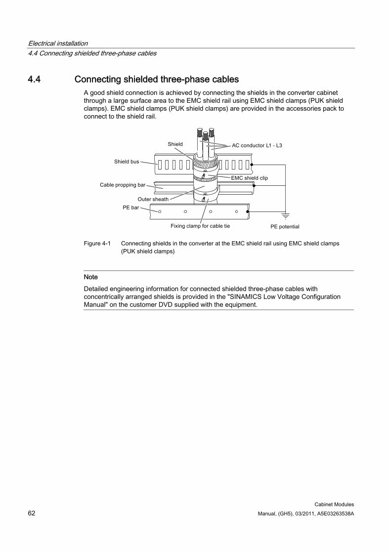
Electrical installation 4.4 Connecting shielded three-phase cables
Cabinet Modules 62 Manual, (GH5), 03/2011, A5E03263538A
4.4 Connecting shielded three-phase cables A good shield connection is achieved by connecting the shields in the converter cabinet through a large surface area to the EMC shield rail using EMC shield clamps (PUK shield clamps). EMC shield clamps (PUK shield clamps) are provided in the accessories pack to connect to the shield rail.
Figure 4-1 Connecting shields in the converter at the EMC shield rail using EMC shield clamps
(PUK shield clamps)
Note
Detailed engineering information for connected shielded three-phase cables with concentrically arranged shields is provided in the "SINAMICS Low Voltage Configuration Manual" on the customer DVD supplied with the equipment.
Electrical installation 4.5 Connections
Cabinet Modules Manual, (GH5), 03/2011, A5E03263538A 63
4.5 Connections
4.5.1 Connection overview
Connection overview The following table shows the connections between the individual Cabinet Modules and their connections. When supplied as transport unit (Option Y11, transport units assembled in the factory), these connections only have to be established between the individual transport units as configured. The connections are established within transport units in the factory.
Note System circuit diagram and layout plan
The table only shows the maximum possible number of connections to be established.
The individual connections that have to be established are defined in the system planning and configuring phases. See the system circuit diagram and layout plan.
Table 4- 2 Connection overview for Cabinet Modules
Connection Required connections for Cabinet Modules Line
Connection Module
Basic Line
Module
Smart Line
Module
Active Line
Module
Booksize Base
Cabinet
Booksize Cabinet
Kit
Motor Module Chassis format
Central Braking Module
Auxiliary Power Supply Module
PE busbar Yes Yes Yes Yes Yes No Yes Yes Yes DC busbars between the Cabinet Modules
* Yes Yes Yes Yes No Yes Yes *
Auxiliary power supply system
No No Yes Yes Yes No Yes Yes Yes
Line connection Yes No No No No No No No Yes Motor cables No No No No No Yes Yes No No Braking resistor No * * * No No * Yes No
* optional
Electrical installation 4.5 Connections
Cabinet Modules 64 Manual, (GH5), 03/2011, A5E03263538A
4.5.2 PE busbar
4.5.2.1 General information
Availability PE busbars are included in the following S120 Cabinet Modules:
Line Connection Modules
Basic Line Modules
Smart Line Modules
Active Line Modules
Booksize Base Cabinets
Chassis format Motor Modules
Central Braking Modules
Auxiliary Power Supply Modules
Description Each Cabinet Module contains a PE busbar for grounding the components installed in the cabinet. For all cabinet units, the busbar is a 60 x 10 mm nickel-plated bar. It is located at the bottom of the cabinet and is secured on the left and right to the ground straps in the cabinet.
Note
When connecting the ground connections to the PE busbar, make sure that the cabinet doors will still close.
4.5.2.2 Connection for side-by-side installation of cabinet units A connection jumper for the PE busbar is supplied with every cabinet.
Note
Installing the transport units as well as connecting the transport units with one another (see Chapter "Mechanical installation", Section "Connection for side-by-side installation of cabinet units"), must have been completed!
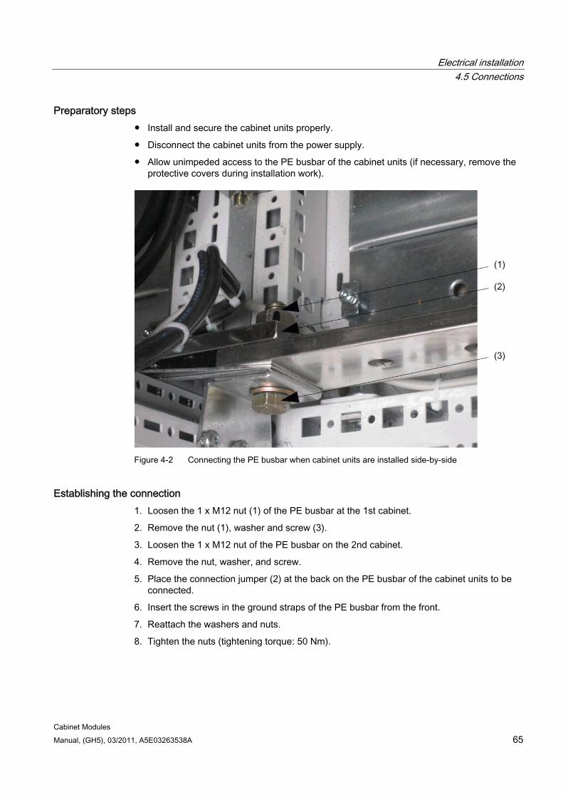
Electrical installation 4.5 Connections
Cabinet Modules Manual, (GH5), 03/2011, A5E03263538A 65
Preparatory steps Install and secure the cabinet units properly.
Disconnect the cabinet units from the power supply.
Allow unimpeded access to the PE busbar of the cabinet units (if necessary, remove the protective covers during installation work).
Figure 4-2 Connecting the PE busbar when cabinet units are installed side-by-side
Establishing the connection 1. Loosen the 1 x M12 nut (1) of the PE busbar at the 1st cabinet.
2. Remove the nut (1), washer and screw (3).
3. Loosen the 1 x M12 nut of the PE busbar on the 2nd cabinet.
4. Remove the nut, washer, and screw.
5. Place the connection jumper (2) at the back on the PE busbar of the cabinet units to be connected.
6. Insert the screws in the ground straps of the PE busbar from the front.
7. Reattach the washers and nuts.
8. Tighten the nuts (tightening torque: 50 Nm).
Electrical installation 4.5 Connections
Cabinet Modules 66 Manual, (GH5), 03/2011, A5E03263538A
4.5.2.3 Connection according to the system-side grounding concept
DANGER Once you have established the connections to the PE busbar in the cabinet and/or established the connections to the PE busbar across more than one cabinet unit, you must establish a connection to the central ground of the entire system.
4.5.2.4 Connecting external cables to the PE busbar
CAUTION When external cables that are to be connected to the PE busbar have been laid, make sure that the cabinet doors close properly.
Preparatory steps Install and secure the cabinet units properly.
Make sure that all the necessary safety measures have been taken at the installation location.
Observe the "five safety rules".
Allow unimpeded access to the PE busbar of the cabinet units (if necessary, remove the protective covers during installation work).
Establishing the connection 1. Insert the screw from the front.
2. Attach the cable lug from behind.
3. Attach the nuts and, if necessary, the washers and tighten (torque: 50 Nm).
Electrical installation 4.5 Connections
Cabinet Modules Manual, (GH5), 03/2011, A5E03263538A 67
4.5.3 DC busbar
4.5.3.1 General information
Availability The DC busbar is always integrated in the following S120 Cabinet Modules and must be ordered as option M80 to M87:
Basic Line Modules
Smart Line Modules
Active Line Modules
Booksize Base Cabinets
Chassis format Motor Modules
Central Braking Modules
Description The DC busbar is used to connect Line Modules with Motor Modules; the connection is made using prefabricated busbar sets with different current-conducting capacities.
The DC busbar can be optionally included in the following Cabinet Modules:
Line Connection Module
Auxiliary Power Supply Module
4.5.3.2 Connection for side-by-side installation of cabinet units
Note
The procedure described below uses a DC busbar 1 x 60 x 10 mm (option M80) as an example, but applies to all other DC busbar versions as well.
For the other available versions, the number of jumpers used on each busbar for connecting the DC busbar is as follows: 1 jumper for each DC busbar for 1 x nn x 10 busbars (options M80 to M82) 2 jumpers for a DC busbar comprising 2 x nn x 10 busbars (options M83 to M85) 3 jumpers for a DC busbar comprising 3 x nn x 10 busbars (options M86 and M87)
A connection jumper (① in the diagram below) on the right side of the DC busbar in the cabinet is used to connect the DC busbar across several Cabinet Modules. This connection jumper is already integrated in every DC busbar of the Cabinet Modules.
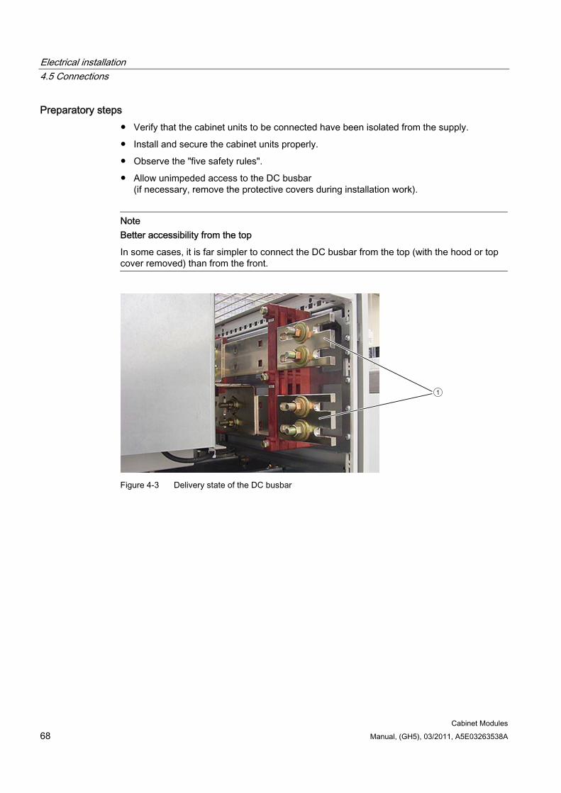
Electrical installation 4.5 Connections
Cabinet Modules 68 Manual, (GH5), 03/2011, A5E03263538A
Preparatory steps Verify that the cabinet units to be connected have been isolated from the supply.
Install and secure the cabinet units properly.
Observe the "five safety rules".
Allow unimpeded access to the DC busbar (if necessary, remove the protective covers during installation work).
Note Better accessibility from the top
In some cases, it is far simpler to connect the DC busbar from the top (with the hood or top cover removed) than from the front.
1
Figure 4-3 Delivery state of the DC busbar
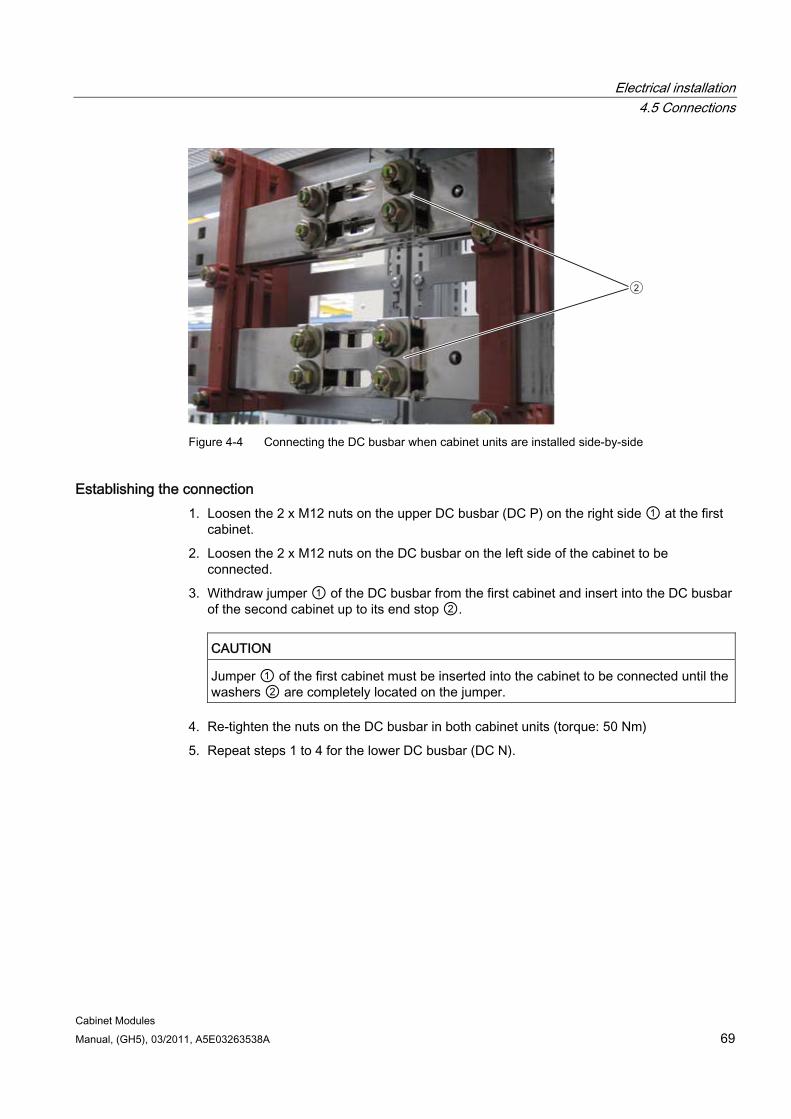
Electrical installation 4.5 Connections
Cabinet Modules Manual, (GH5), 03/2011, A5E03263538A 69
2
Figure 4-4 Connecting the DC busbar when cabinet units are installed side-by-side
Establishing the connection 1. Loosen the 2 x M12 nuts on the upper DC busbar (DC P) on the right side ① at the first
cabinet.
2. Loosen the 2 x M12 nuts on the DC busbar on the left side of the cabinet to be connected.
3. Withdraw jumper ① of the DC busbar from the first cabinet and insert into the DC busbar of the second cabinet up to its end stop ②.
CAUTION
Jumper ① of the first cabinet must be inserted into the cabinet to be connected until the washers ② are completely located on the jumper.
4. Re-tighten the nuts on the DC busbar in both cabinet units (torque: 50 Nm)
5. Repeat steps 1 to 4 for the lower DC busbar (DC N).
Electrical installation 4.5 Connections
Cabinet Modules 70 Manual, (GH5), 03/2011, A5E03263538A
CAUTION The screws must only be loosened rather than removed because otherwise the nuts could fall into the device.
The torque (50 Nm) must be observed to avoid excessive heating of the terminal contacts during operation.
For the busbar systems, all jumpers of the DC busbar must always be connected.
For each cabinet row installed, you must mount one side panel on the right (option M26) and one on the left (option M27).
Before mounting the side panels on an installed cabinet row, you must remove any jumpers present in the DC busbars of the cabinet on the right.
Note
In the case of transport units with standard integrated DC busbars within the cabinet group, you only need to connect the ends of the busbars of the transport units.
4.5.4 Auxiliary power supply system
4.5.4.1 General information
Availability To facilitate the auxiliary voltage supply to S120 Cabinet Modules, the individual modules are fitted with a special, standardized auxiliary voltage supply system. This system is delivered pre-installed. The cabling required from the auxiliary power module into the relevant Cabinet Module are factory-installed.
In the following S120 Cabinet Modules, two further voltage taps are available to the customer on the auxiliary power module for each voltage level:
Smart Line Modules
Active Line Modules
Booksize Base Cabinets
Chassis format Motor Modules
Central Braking Modules
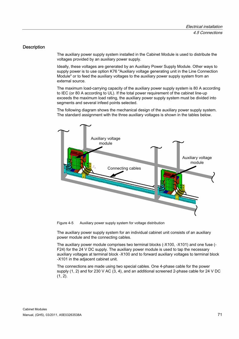
Electrical installation 4.5 Connections
Cabinet Modules Manual, (GH5), 03/2011, A5E03263538A 71
Description The auxiliary power supply system installed in the Cabinet Module is used to distribute the voltages provided by an auxiliary power supply.
Ideally, these voltages are generated by an Auxiliary Power Supply Module. Other ways to supply power is to use option K76 "Auxiliary voltage generating unit in the Line Connection Module" or to feed the auxiliary voltages to the auxiliary power supply system from an external source.
The maximum load-carrying capacity of the auxiliary power supply system is 80 A according to IEC (or 80 A according to UL). If the total power requirement of the cabinet line-up exceeds the maximum load rating, the auxiliary power supply system must be divided into segments and several infeed points selected.
The following diagram shows the mechanical design of the auxiliary power supply system. The standard assignment with the three auxiliary voltages is shown in the tables below.
Figure 4-5 Auxiliary power supply system for voltage distribution
The auxiliary power supply system for an individual cabinet unit consists of an auxiliary power module and the connecting cables.
The auxiliary power module comprises two terminal blocks (-X100, -X101) and one fuse (-F24) for the 24 V DC supply. The auxiliary power module is used to tap the necessary auxiliary voltages at terminal block -X100 and to forward auxiliary voltages to terminal block -X101 in the adjacent cabinet unit.
The connections are made using two special cables. One 4-phase cable for the power supply (1, 2) and for 230 V AC (3, 4), and an additional screened 2-phase cable for 24 V DC (1, 2).
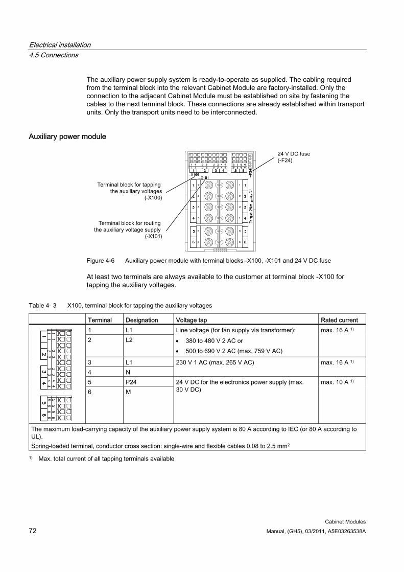
Electrical installation 4.5 Connections
Cabinet Modules 72 Manual, (GH5), 03/2011, A5E03263538A
The auxiliary power supply system is ready-to-operate as supplied. The cabling required from the terminal block into the relevant Cabinet Module are factory-installed. Only the connection to the adjacent Cabinet Module must be established on site by fastening the cables to the next terminal block. These connections are already established within transport units. Only the transport units need to be interconnected.
Auxiliary power module
Figure 4-6 Auxiliary power module with terminal blocks -X100, -X101 and 24 V DC fuse
At least two terminals are always available to the customer at terminal block -X100 for tapping the auxiliary voltages.
Table 4- 3 X100, terminal block for tapping the auxiliary voltages
Terminal Designation Voltage tap Rated current 1 L1 2 L2
Line voltage (for fan supply via transformer): 380 to 480 V 2 AC or 500 to 690 V 2 AC (max. 759 V AC)
max. 16 A 1)
3 L1 4 N
230 V 1 AC (max. 265 V AC) max. 16 A 1)
5 P24
6 M 24 V DC for the electronics power supply (max. 30 V DC)
max. 10 A 1)
The maximum load-carrying capacity of the auxiliary power supply system is 80 A according to IEC (or 80 A according to UL). Spring-loaded terminal, conductor cross section: single-wire and flexible cables 0.08 to 2.5 mm2
1) Max. total current of all tapping terminals available
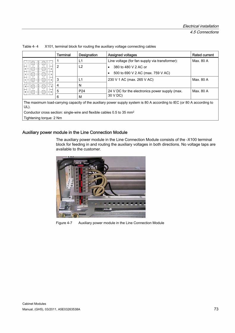
Electrical installation 4.5 Connections
Cabinet Modules Manual, (GH5), 03/2011, A5E03263538A 73
Table 4- 4 X101, terminal block for routing the auxiliary voltage connecting cables
Terminal Designation Assigned voltages Rated current 1 L1 2 L2
Line voltage (for fan supply via transformer): 380 to 480 V 2 AC or 500 to 690 V 2 AC (max. 759 V AC)
Max. 80 A
3 L1 4 N
230 V 1 AC (max. 265 V AC) Max. 80 A
5 P24 6 M
24 V DC for the electronics power supply (max. 30 V DC)
Max. 80 A
The maximum load-carrying capacity of the auxiliary power supply system is 80 A according to IEC (or 80 A according to UL). Conductor cross section: single-wire and flexible cables 0.5 to 35 mm2 Tightening torque: 2 Nm
Auxiliary power module in the Line Connection Module The auxiliary power module in the Line Connection Module consists of the -X100 terminal block for feeding in and routing the auxiliary voltages in both directions. No voltage taps are available to the customer.
Figure 4-7 Auxiliary power module in the Line Connection Module
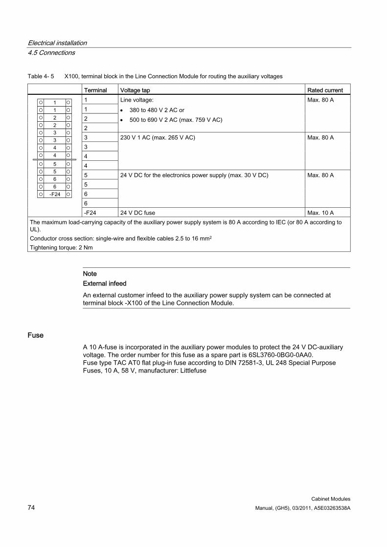
Electrical installation 4.5 Connections
Cabinet Modules 74 Manual, (GH5), 03/2011, A5E03263538A
Table 4- 5 X100, terminal block in the Line Connection Module for routing the auxiliary voltages
Terminal Voltage tap Rated current 1 1 2 2
Line voltage: 380 to 480 V 2 AC or 500 to 690 V 2 AC (max. 759 V AC)
Max. 80 A
3 3 4 4
230 V 1 AC (max. 265 V AC) Max. 80 A
5 5 6 6
24 V DC for the electronics power supply (max. 30 V DC) Max. 80 A
-F24 24 V DC fuse Max. 10 A The maximum load-carrying capacity of the auxiliary power supply system is 80 A according to IEC (or 80 A according to UL). Conductor cross section: single-wire and flexible cables 2.5 to 16 mm2 Tightening torque: 2 Nm
Note External infeed
An external customer infeed to the auxiliary power supply system can be connected at terminal block -X100 of the Line Connection Module.
Fuse A 10 A-fuse is incorporated in the auxiliary power modules to protect the 24 V DC-auxiliary voltage. The order number for this fuse as a spare part is 6SL3760-0BG0-0AA0. Fuse type TAC AT0 flat plug-in fuse according to DIN 72581-3, UL 248 Special Purpose Fuses, 10 A, 58 V, manufacturer: Littlefuse
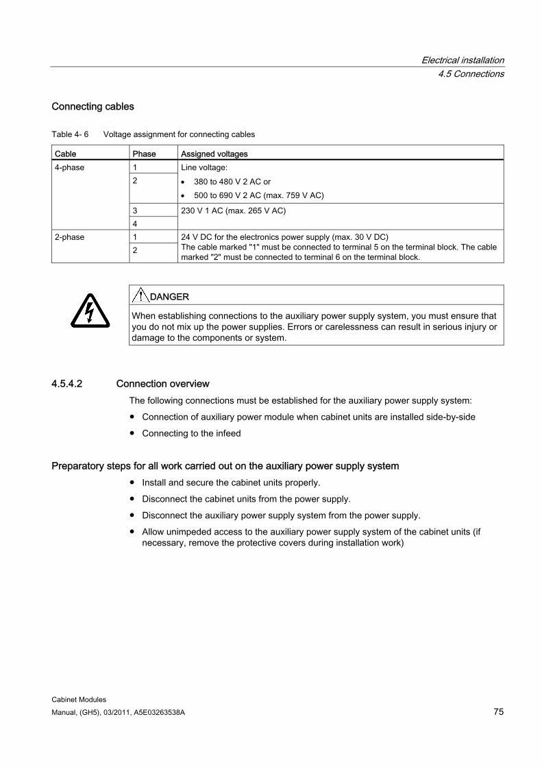
Electrical installation 4.5 Connections
Cabinet Modules Manual, (GH5), 03/2011, A5E03263538A 75
Connecting cables
Table 4- 6 Voltage assignment for connecting cables
Cable Phase Assigned voltages 1 2
Line voltage: 380 to 480 V 2 AC or 500 to 690 V 2 AC (max. 759 V AC)
3
4-phase
4 230 V 1 AC (max. 265 V AC)
1 2-phase 2
24 V DC for the electronics power supply (max. 30 V DC) The cable marked "1" must be connected to terminal 5 on the terminal block. The cable marked "2" must be connected to terminal 6 on the terminal block.
DANGER
When establishing connections to the auxiliary power supply system, you must ensure that you do not mix up the power supplies. Errors or carelessness can result in serious injury or damage to the components or system.
4.5.4.2 Connection overview The following connections must be established for the auxiliary power supply system:
Connection of auxiliary power module when cabinet units are installed side-by-side
Connecting to the infeed
Preparatory steps for all work carried out on the auxiliary power supply system Install and secure the cabinet units properly.
Disconnect the cabinet units from the power supply.
Disconnect the auxiliary power supply system from the power supply.
Allow unimpeded access to the auxiliary power supply system of the cabinet units (if necessary, remove the protective covers during installation work)
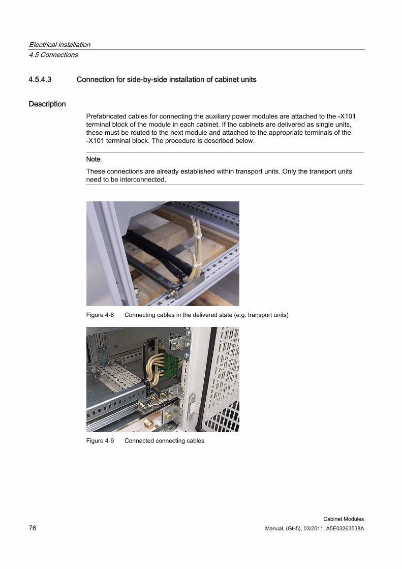
Electrical installation 4.5 Connections
Cabinet Modules 76 Manual, (GH5), 03/2011, A5E03263538A
4.5.4.3 Connection for side-by-side installation of cabinet units
Description Prefabricated cables for connecting the auxiliary power modules are attached to the -X101 terminal block of the module in each cabinet. If the cabinets are delivered as single units, these must be routed to the next module and attached to the appropriate terminals of the -X101 terminal block. The procedure is described below.
Note
These connections are already established within transport units. Only the transport units need to be interconnected.
Figure 4-8 Connecting cables in the delivered state (e.g. transport units)
Figure 4-9 Connected connecting cables
Electrical installation 4.5 Connections
Cabinet Modules Manual, (GH5), 03/2011, A5E03263538A 77
Establishing the connection
CAUTION Sharp edges in the cabinet unit can cause injury when connecting the auxiliary power supply system.
1. Disconnect the cabinet from the power supply.
2. Observe the "five safety rules".
3. Fasten the cables to terminal block -X101 of the next module: 4-phase cable (1-2): for line voltage to terminals 1 and 2 4-phase cable (3-4): for 230 V AC to terminals 3 and 4 2-phase cable (1-2): for 24 V DC to terminals 5 and 6
Note Establishing the connection for Basic Line Modules
Basic Line Modules do not contain auxiliary power modules. The 24 V DC voltage supply is provided by connecting the 2-phase cable included in the Basic Line Module to the auxiliary power module of the adjacent cabinet unit.
DANGER
When establishing connections to the auxiliary power supply system, you must ensure that you do not mix up the power supplies. Errors or carelessness can result in serious injury or damage to the components or system.
4.5.4.4 Connecting to the infeed
Description The voltages provided on the auxiliary power supply system must be produced by an auxiliary power supply (e.g. by an Auxiliary Power Supply Module or by Option K76 "Auxiliary voltage generating unit in the Line Connection Module").
If an Auxiliary Power Supply Module is not available to supply power to the auxiliary power supply system or if the Auxiliary Power Supply Module and the Cabinet Modules to be supplied are installed in different parts of the cabinet line-up, an auxiliary power module in the Line Connection Module can be used to feed power to the auxiliary power supply system. Further alternatives for feeding power are in the first or last auxiliary power module of the drive line-up. The maximum current-carrying capacity of the auxiliary power supply system is 80 A. In the case of the external power supply, this must be fuse protected on the line side.
Electrical installation 4.5 Connections
Cabinet Modules 78 Manual, (GH5), 03/2011, A5E03263538A
4.5.5 Connecting the motor cables
Preparatory steps Install and secure the cabinet units properly.
Disconnect the cabinet units from the power supply.
Make sure that all the necessary safety measures have been taken at the installation location.
Observe the "five safety rules".
DANGER
When connecting permanently excited synchronous machines, you must ensure that the motor is shut down or electrically isolated (option L34); otherwise, the voltage generated can be lethal.
Motor Modules Booksize Cabinet Kit
Table 4- 7 Motor connection, Motor Modules
Terminals Technical specifications DCP, DCN DC power input
Voltage: 510 ... 750 V DC
U2/T1, V2/T2, W2/T3 3 AC power output
Voltage: 0 V 3 AC to 0.72 x DC link voltage Terminals: 6 ... 95 mm2 (→ see technical data)
Chassis format Motor Modules
Table 4- 8 Motor connection, Motor Modules
Terminals Technical specifications DCP, DCN DC power input
Voltage: 510 ... 750 V DC 675 ... 1080 V DC
U2/T1, V2/T2, W2/T3 3 AC power output
Voltage: 0 V 3 AC to 0.72 x DC link voltage Connection: M12 / 50 Nm for cable lugs in accordance with DIN 46234 or DIN 46235
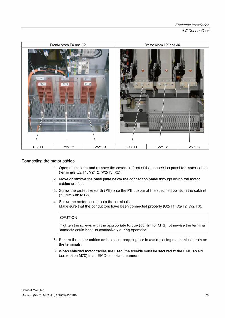
Electrical installation 4.5 Connections
Cabinet Modules Manual, (GH5), 03/2011, A5E03263538A 79
Frame sizes FX and GX Frame sizes HX and JX
-U2/-T1 -V2/-T2 -W2/-T3 -U2/-T1 -V2/-T2 -W2/-T3
Connecting the motor cables 1. Open the cabinet and remove the covers in front of the connection panel for motor cables
(terminals U2/T1, V2/T2, W2/T3; X2).
2. Move or remove the base plate below the connection panel through which the motor cables are fed.
3. Screw the protective earth (PE) onto the PE busbar at the specified points in the cabinet (50 Nm with M12).
4. Screw the motor cables onto the terminals. Make sure that the conductors have been connected properly (U2/T1, V2/T2, W2/T3).
CAUTION
Tighten the screws with the appropriate torque (50 Nm for M12), otherwise the terminal contacts could heat up excessively during operation.
5. Secure the motor cables on the cable propping bar to avoid placing mechanical strain on the terminals.
6. When shielded motor cables are used, the shields must be secured to the EMC shield bus (option M70) in an EMC-compliant manner.
Electrical installation 4.5 Connections
Cabinet Modules 80 Manual, (GH5), 03/2011, A5E03263538A
Note
For the position of the connections for motor cables, see the layout diagrams included on the customer DVD supplied with the device.
The motor ground should be fed back directly to the cabinet (PE busbar) and connected.
Connection cross sections Refer to the "Technical data" for the Motor Modules, "Cabinet Modules" chapter for the maximum connection cross sections.
Direction of motor rotation EN 60034-7 defines the two ends of an electric motor as follows:
D (Drive End): Usually the drive end of the motor
N (Non-Drive End): Usually the non-drive end of the motor
An electric motor rotates clockwise if the shaft rotates in the clockwise direction when viewing the D end.
For electric motors with 2 shaft ends, the direction of rotation must be determined based on the shaft end specified as the drive end.
For clockwise rotation, the electric motor must be connected according to the following table.
Table 4- 9 Cabinet and motor connection terminals
Cabinet (motor connection terminals) Motor (connection terminals) U2/T1 U V2/T2 V W2/T3 W
In contrast to the connection for the clockwise phase sequence, two phases have to be reversed with a counter-clockwise phase sequence (looking at the drive shaft).
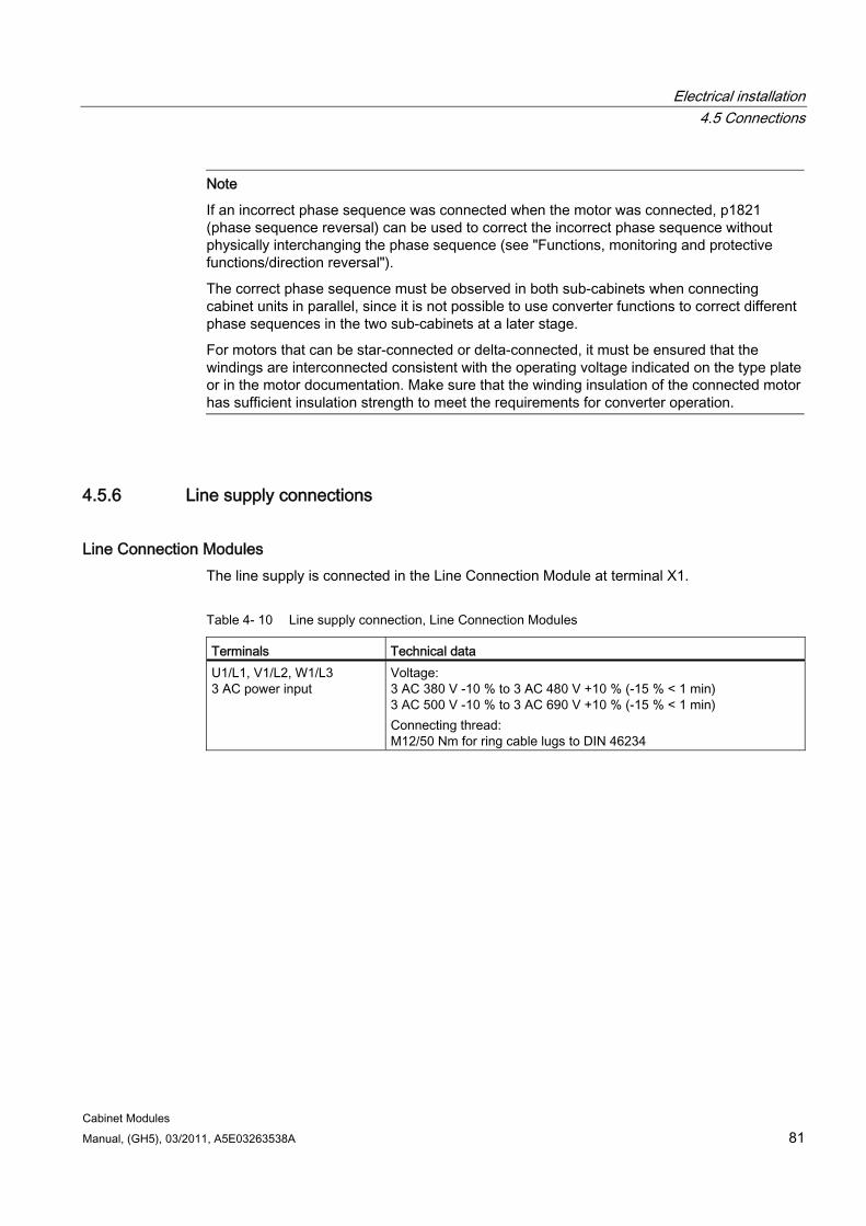
Electrical installation 4.5 Connections
Cabinet Modules Manual, (GH5), 03/2011, A5E03263538A 81
Note
If an incorrect phase sequence was connected when the motor was connected, p1821 (phase sequence reversal) can be used to correct the incorrect phase sequence without physically interchanging the phase sequence (see "Functions, monitoring and protective functions/direction reversal").
The correct phase sequence must be observed in both sub-cabinets when connecting cabinet units in parallel, since it is not possible to use converter functions to correct different phase sequences in the two sub-cabinets at a later stage.
For motors that can be star-connected or delta-connected, it must be ensured that the windings are interconnected consistent with the operating voltage indicated on the type plate or in the motor documentation. Make sure that the winding insulation of the connected motor has sufficient insulation strength to meet the requirements for converter operation.
4.5.6 Line supply connections
Line Connection Modules The line supply is connected in the Line Connection Module at terminal X1.
Table 4- 10 Line supply connection, Line Connection Modules
Terminals Technical data U1/L1, V1/L2, W1/L3 3 AC power input
Voltage: 3 AC 380 V -10 % to 3 AC 480 V +10 % (-15 % < 1 min) 3 AC 500 V -10 % to 3 AC 690 V +10 % (-15 % < 1 min) Connecting thread: M12/50 Nm for ring cable lugs to DIN 46234
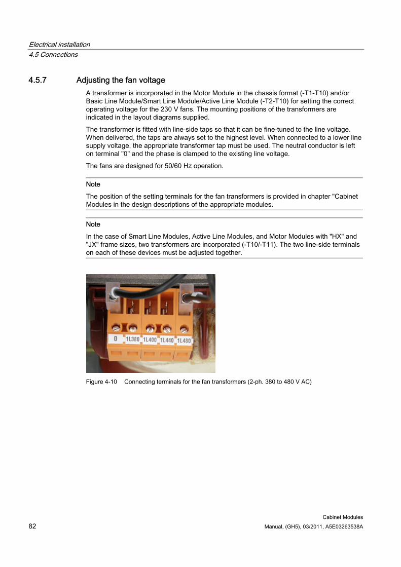
Electrical installation 4.5 Connections
Cabinet Modules 82 Manual, (GH5), 03/2011, A5E03263538A
4.5.7 Adjusting the fan voltage A transformer is incorporated in the Motor Module in the chassis format (-T1-T10) and/or Basic Line Module/Smart Line Module/Active Line Module (-T2-T10) for setting the correct operating voltage for the 230 V fans. The mounting positions of the transformers are indicated in the layout diagrams supplied.
The transformer is fitted with line-side taps so that it can be fine-tuned to the line voltage. When delivered, the taps are always set to the highest level. When connected to a lower line supply voltage, the appropriate transformer tap must be used. The neutral conductor is left on terminal "0" and the phase is clamped to the existing line voltage.
The fans are designed for 50/60 Hz operation.
Note
The position of the setting terminals for the fan transformers is provided in chapter "Cabinet Modules in the design descriptions of the appropriate modules.
Note
In the case of Smart Line Modules, Active Line Modules, and Motor Modules with "HX" and "JX" frame sizes, two transformers are incorporated (-T10/-T11). The two line-side terminals on each of these devices must be adjusted together.
Figure 4-10 Connecting terminals for the fan transformers (2-ph. 380 to 480 V AC)
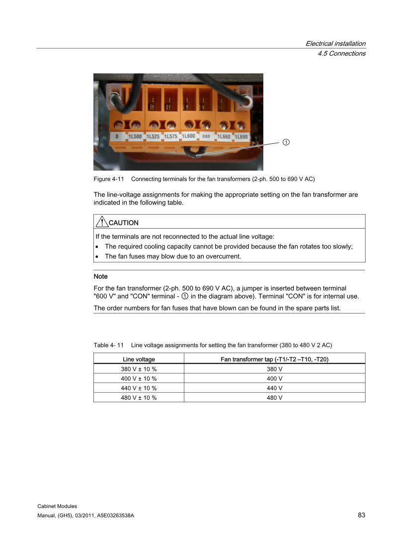
Electrical installation 4.5 Connections
Cabinet Modules Manual, (GH5), 03/2011, A5E03263538A 83
Figure 4-11 Connecting terminals for the fan transformers (2-ph. 500 to 690 V AC)
The line-voltage assignments for making the appropriate setting on the fan transformer are indicated in the following table.
CAUTION If the terminals are not reconnected to the actual line voltage: The required cooling capacity cannot be provided because the fan rotates too slowly; The fan fuses may blow due to an overcurrent.
Note
For the fan transformer (2-ph. 500 to 690 V AC), a jumper is inserted between terminal "600 V" and "CON" terminal - ① in the diagram above). Terminal "CON" is for internal use.
The order numbers for fan fuses that have blown can be found in the spare parts list.
Table 4- 11 Line voltage assignments for setting the fan transformer (380 to 480 V 2 AC)
Line voltage Fan transformer tap (-T1/-T2 –T10, -T20) 380 V ± 10 % 380 V 400 V ± 10 % 400 V 440 V ± 10 % 440 V 480 V ± 10 % 480 V
Electrical installation 4.5 Connections
Cabinet Modules 84 Manual, (GH5), 03/2011, A5E03263538A
Table 4- 12 Line voltage assignments for setting the fan transformer (500 to 690 V 2 AC)
Line voltage Fan transformer tap (-T1/-T2 -T10, -T20) 500 V ± 10 % 500 V 525 V ± 10 % 525 V 575 V ± 10 % 575 V 600 V ± 10 % 600 V 660 V ± 10 % 660 V 690 V ± 10 % 690 V
4.5.8 Connecting Cabinet Modules to non-grounded line supplies (IT systems) When the Cabinet Modules are operated on an non-grounded line supply system (IT system), the integrated EMC filters must be deactivated by unscrewing a connection bar in the following Cabinet Modules:
Basic Line Modules
Smart Line Modules (for frame sizes HX and JX, the connection bar is located behind the fan)
Active Line Modules (connection bar in the Active Interface Module)
WARNING Failing to remove the connection bar to the EMC filter when connected to a non-grounded line supply (IT system) can cause significant damage to the device.
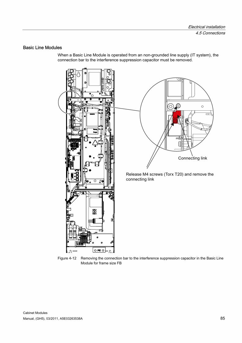
Electrical installation 4.5 Connections
Cabinet Modules Manual, (GH5), 03/2011, A5E03263538A 85
Basic Line Modules When a Basic Line Module is operated from an non-grounded line supply (IT system), the connection bar to the interference suppression capacitor must be removed.
Figure 4-12 Removing the connection bar to the interference suppression capacitor in the Basic Line
Module for frame size FB
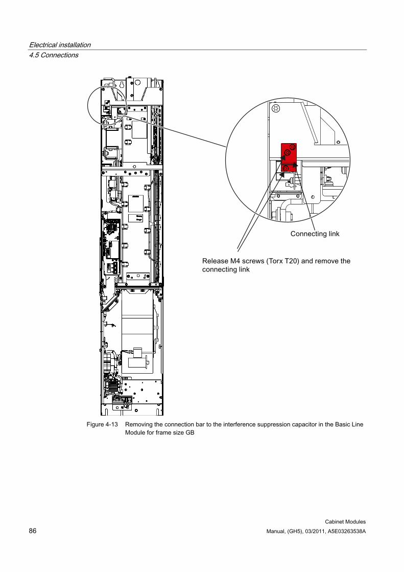
Electrical installation 4.5 Connections
Cabinet Modules 86 Manual, (GH5), 03/2011, A5E03263538A
Figure 4-13 Removing the connection bar to the interference suppression capacitor in the Basic Line
Module for frame size GB
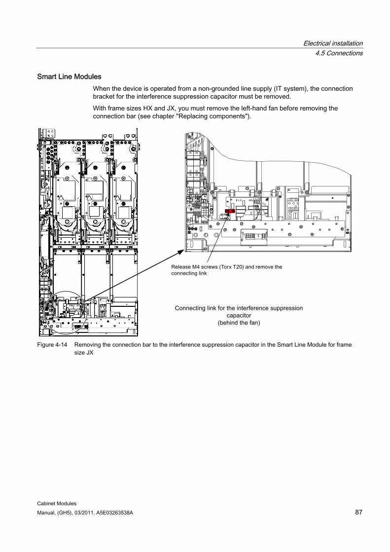
Electrical installation 4.5 Connections
Cabinet Modules Manual, (GH5), 03/2011, A5E03263538A 87
Smart Line Modules When the device is operated from a non-grounded line supply (IT system), the connection bracket for the interference suppression capacitor must be removed.
With frame sizes HX and JX, you must remove the left-hand fan before removing the connection bar (see chapter "Replacing components").
Connecting link for the interference suppression capacitor
(behind the fan)
Figure 4-14 Removing the connection bar to the interference suppression capacitor in the Smart Line Module for frame
size JX
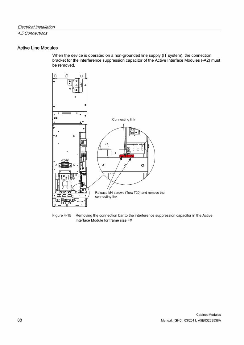
Electrical installation 4.5 Connections
Cabinet Modules 88 Manual, (GH5), 03/2011, A5E03263538A
Active Line Modules When the device is operated on a non-grounded line supply (IT system), the connection bracket for the interference suppression capacitor of the Active Interface Modules (-A2) must be removed.
Figure 4-15 Removing the connection bar to the interference suppression capacitor in the Active
Interface Module for frame size FX
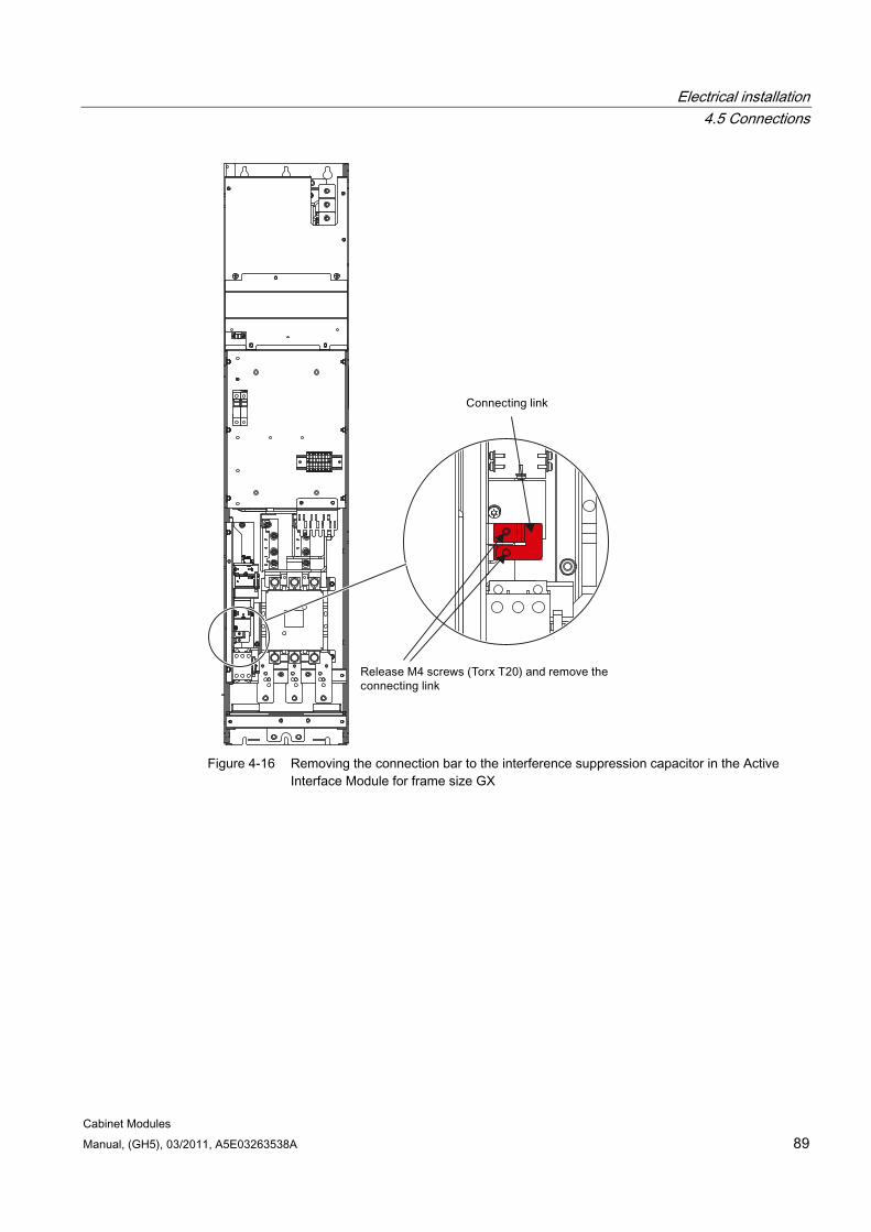
Electrical installation 4.5 Connections
Cabinet Modules Manual, (GH5), 03/2011, A5E03263538A 89
Figure 4-16 Removing the connection bar to the interference suppression capacitor in the Active
Interface Module for frame size GX
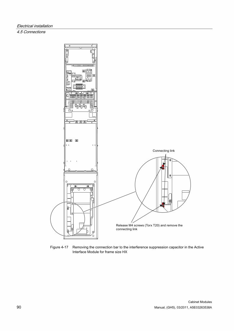
Electrical installation 4.5 Connections
Cabinet Modules 90 Manual, (GH5), 03/2011, A5E03263538A
Figure 4-17 Removing the connection bar to the interference suppression capacitor in the Active
Interface Module for frame size HX
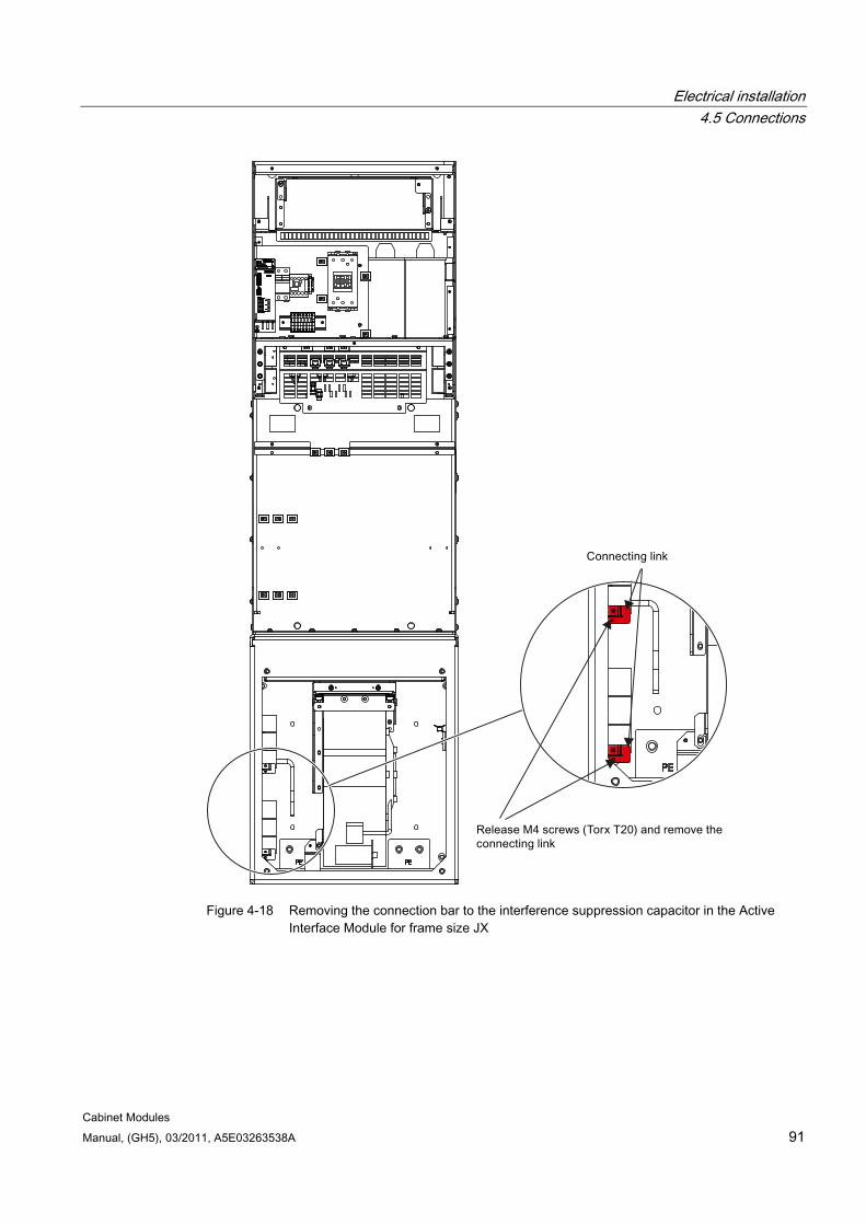
Electrical installation 4.5 Connections
Cabinet Modules Manual, (GH5), 03/2011, A5E03263538A 91
Figure 4-18 Removing the connection bar to the interference suppression capacitor in the Active
Interface Module for frame size JX
Electrical installation 4.5 Connections
Cabinet Modules 92 Manual, (GH5), 03/2011, A5E03263538A
4.5.9 Signal connections
Note
The factory setting and description of the customer terminal blocks are documented in the circuit diagrams.
The location of the customer terminal blocks of the individual Cabinet Modules is documented in the layout diagrams.
The interfaces or customer terminal blocks are documented for the respective Cabinet Modules.
DRIVE-CLiQ cables must be locally routed according to the customer-specific engineering specifications for the entire system.
4.5.10 Other connections Depending on the range of options installed, further connections may have to be made.
For more information about the interfaces of available options, refer to the relevant sections in this manual.
4.5.11 Cable routing
4.5.11.1 General information
DANGER
The work described in this section is carried out in cabinets that are operated in industrial high-voltage installations. During operation, this cabinet contains rotating and live parts. For this reason, there is a risk of severe injury or significant material damage if the required covers are removed without authorization, if it is used or operated incorrectly, or if it has not been properly maintained.
You must read the safety information and application notes.
Electrical installation 4.5 Connections
Cabinet Modules Manual, (GH5), 03/2011, A5E03263538A 93
Basic rules for cable routing The Cabinet Modules are delivered pre-wired.
The following basic rules must always be observed for all Cabinet Modules should any additional cabling and wiring or connection work be necessary.
Observe EMC guidelines.
Use existing routing for cable assemblies.
Always use the shield plates provided (do not bypass them).
Use existing cable propping bars as required.
Attach the cable ties at suitable points on metal frames and cabinet frame profiles.
Use a cabinet upright to route cables into adjacent cabinets.
Refit any covers removed during cable routing before completing the work and commissioning!
Preparatory steps Before starting any cabling or connection work in the Cabinet Modules, ensure that the following measures are performed:
Disconnect the cabinet unit from the power supply.
Observe the "five safety rules".
Allow unimpeded access to the necessary components in the Cabinet Module (if necessary, remove the covers).
Safety and EMC
DANGER All covers removed while the cables were being routed must be replaced before the Cabinet Module is commissioned!
NOTICE When routing cables, utmost care must be taken not to change the internal cabinet wiring!
NOTICE The shield plates must be replaced before the cabinet is commissioned, in order to ensure that shielding is EMC-compliant! The motor cable shields must be secured to the EMC shield bus (option M70) and the PE cables to the PE busbar!
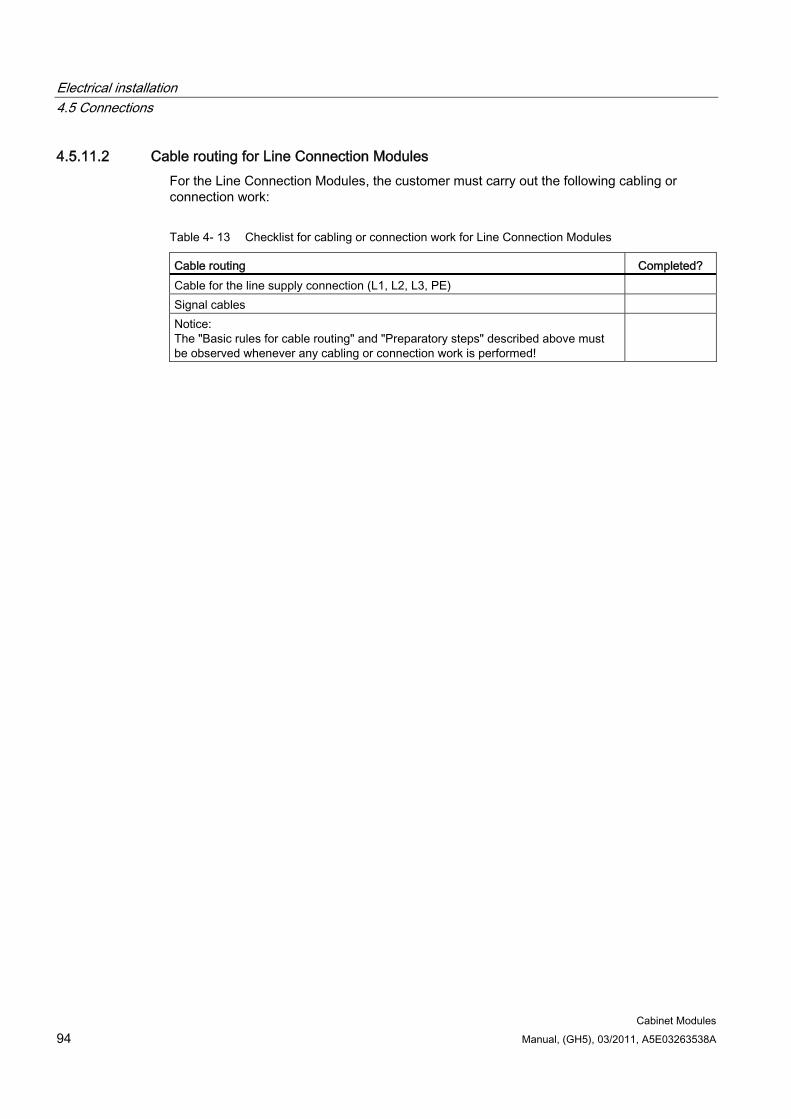
Electrical installation 4.5 Connections
Cabinet Modules 94 Manual, (GH5), 03/2011, A5E03263538A
4.5.11.2 Cable routing for Line Connection Modules For the Line Connection Modules, the customer must carry out the following cabling or connection work:
Table 4- 13 Checklist for cabling or connection work for Line Connection Modules
Cable routing Completed? Cable for the line supply connection (L1, L2, L3, PE) Signal cables Notice: The "Basic rules for cable routing" and "Preparatory steps" described above must be observed whenever any cabling or connection work is performed!
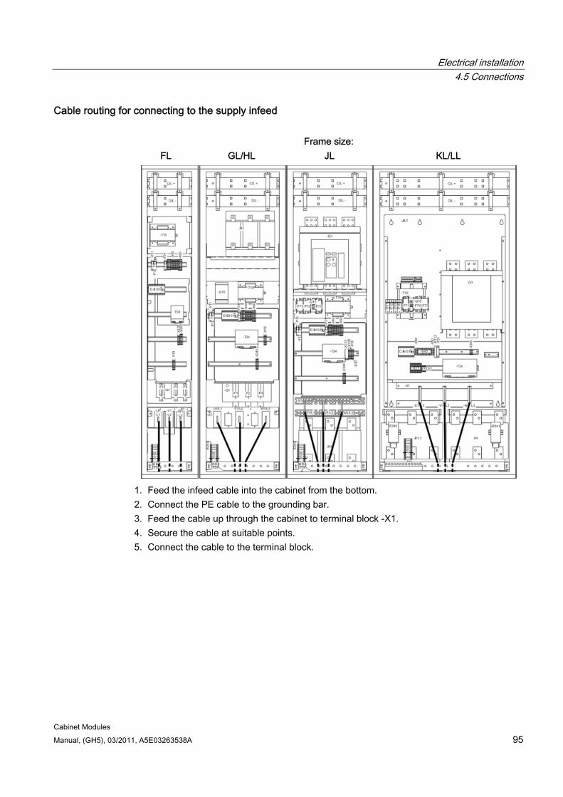
Electrical installation 4.5 Connections
Cabinet Modules Manual, (GH5), 03/2011, A5E03263538A 95
Cable routing for connecting to the supply infeed
Frame size: FL GL/HL JL KL/LL
1. Feed the infeed cable into the cabinet from the bottom. 2. Connect the PE cable to the grounding bar. 3. Feed the cable up through the cabinet to terminal block -X1. 4. Secure the cable at suitable points. 5. Connect the cable to the terminal block.

Electrical installation 4.5 Connections
Cabinet Modules 96 Manual, (GH5), 03/2011, A5E03263538A
Signal cables
Frame size: FL GL/HL JL KL/LL
1. Feed the signal cables into the cabinet from the bottom left. 2. Feed the signal cables up through the cabinet to terminal blocks -X30, -X40, and -X50. 3. Fasten the signal cables at suitable points. 4. Connect the signal cables to the terminal blocks.
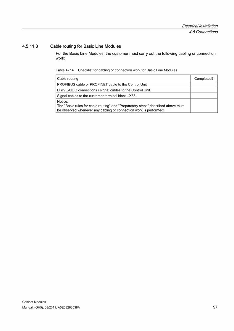
Electrical installation 4.5 Connections
Cabinet Modules Manual, (GH5), 03/2011, A5E03263538A 97
4.5.11.3 Cable routing for Basic Line Modules For the Basic Line Modules, the customer must carry out the following cabling or connection work:
Table 4- 14 Checklist for cabling or connection work for Basic Line Modules
Cable routing Completed? PROFIBUS cable or PROFINET cable to the Control Unit DRIVE-CLiQ connections / signal cables to the Control Unit Signal cables to the customer terminal block –X55 Notice: The "Basic rules for cable routing" and "Preparatory steps" described above must be observed whenever any cabling or connection work is performed!
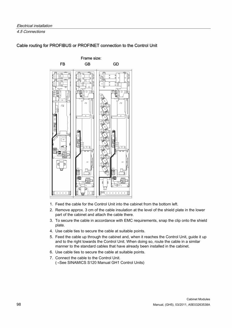
Electrical installation 4.5 Connections
Cabinet Modules 98 Manual, (GH5), 03/2011, A5E03263538A
Cable routing for PROFIBUS or PROFINET connection to the Control Unit
Frame size: FB GB GD
1. Feed the cable for the Control Unit into the cabinet from the bottom left. 2. Remove approx. 3 cm of the cable insulation at the level of the shield plate in the lower
part of the cabinet and attach the cable there. 3. To secure the cable in accordance with EMC requirements, snap the clip onto the shield
plate. 4. Use cable ties to secure the cable at suitable points. 5. Feed the cable up through the cabinet and, when it reaches the Control Unit, guide it up
and to the right towards the Control Unit. When doing so, route the cable in a similar manner to the standard cables that have already been installed in the cabinet.
6. Use cable ties to secure the cable at suitable points. 7. Connect the cable to the Control Unit.
(→See SINAMICS S120 Manual GH1 Control Units)
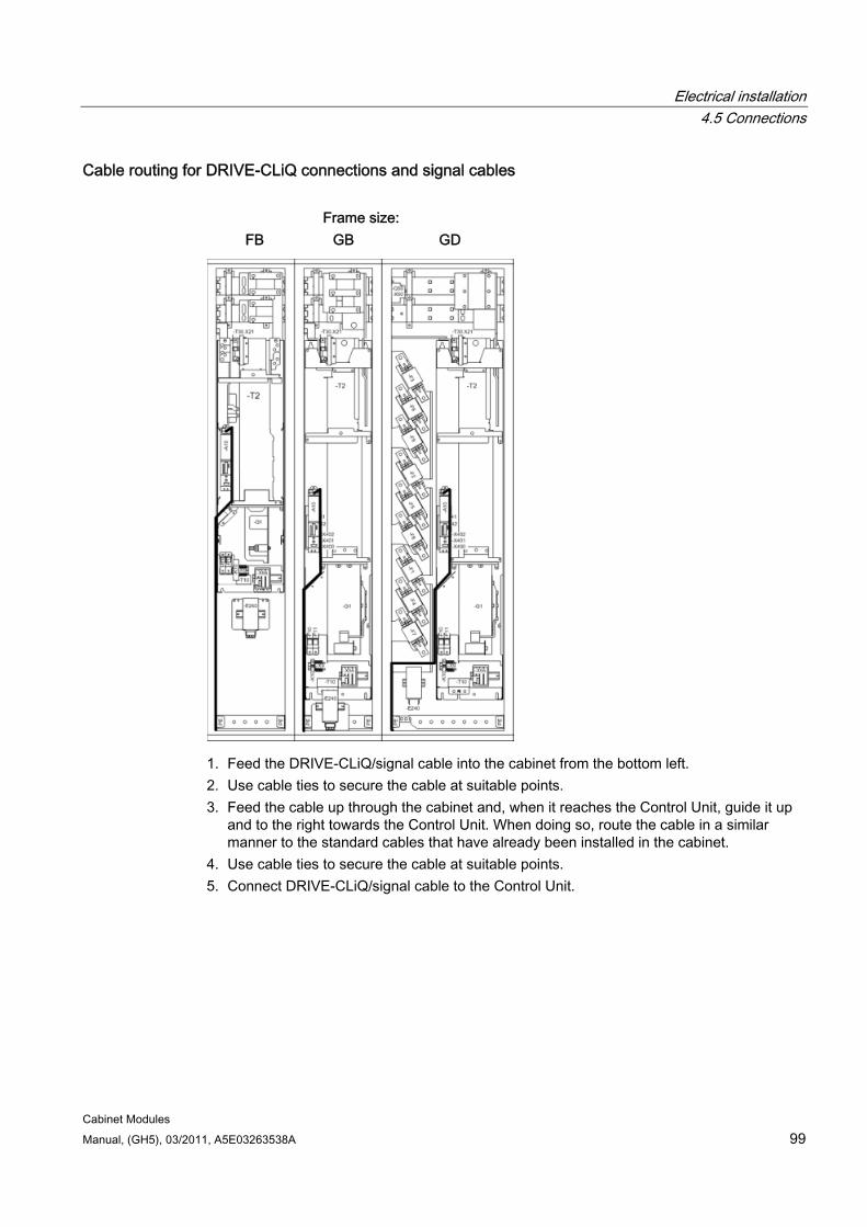
Electrical installation 4.5 Connections
Cabinet Modules Manual, (GH5), 03/2011, A5E03263538A 99
Cable routing for DRIVE-CLiQ connections and signal cables
Frame size: FB GB GD
1. Feed the DRIVE-CLiQ/signal cable into the cabinet from the bottom left. 2. Use cable ties to secure the cable at suitable points. 3. Feed the cable up through the cabinet and, when it reaches the Control Unit, guide it up
and to the right towards the Control Unit. When doing so, route the cable in a similar manner to the standard cables that have already been installed in the cabinet.
4. Use cable ties to secure the cable at suitable points. 5. Connect DRIVE-CLiQ/signal cable to the Control Unit.
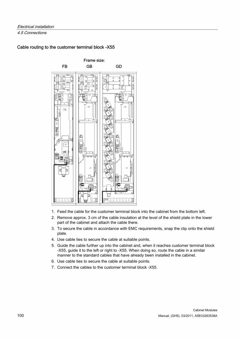
Electrical installation 4.5 Connections
Cabinet Modules 100 Manual, (GH5), 03/2011, A5E03263538A
Cable routing to the customer terminal block -X55
Frame size: FB GB GD
1. Feed the cable for the customer terminal block into the cabinet from the bottom left. 2. Remove approx. 3 cm of the cable insulation at the level of the shield plate in the lower
part of the cabinet and attach the cable there. 3. To secure the cable in accordance with EMC requirements, snap the clip onto the shield
plate. 4. Use cable ties to secure the cable at suitable points. 5. Guide the cable further up into the cabinet and, when it reaches customer terminal block
-X55, guide it to the left or right to -X55. When doing so, route the cable in a similar manner to the standard cables that have already been installed in the cabinet.
6. Use cable ties to secure the cable at suitable points. 7. Connect the cables to the customer terminal block -X55.

Electrical installation 4.5 Connections
Cabinet Modules Manual, (GH5), 03/2011, A5E03263538A 101
4.5.11.4 Cable routing for Smart Line Modules For the Smart Line Modules, the customer must carry out the following cabling or connection work:
Table 4- 15 Checklist for cabling or connection work for Smart Line Modules
Cable routing Completed? PROFIBUS cable or PROFINET cable to the Control Unit DRIVE-CLiQ connections / signal cables to the Control Unit Signal cables to the customer terminal block –X55 Notice: The "Basic rules for cable routing" and "Preparatory steps" described above must be observed whenever any cabling or connection work is performed!
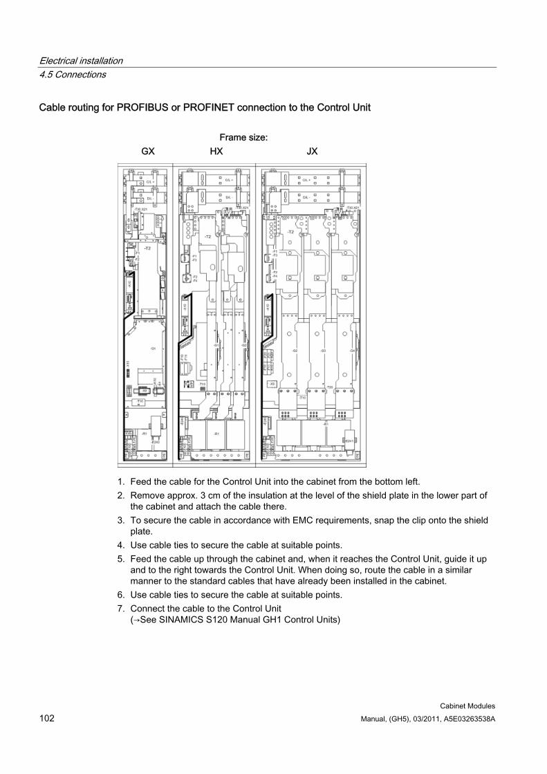
Electrical installation 4.5 Connections
Cabinet Modules 102 Manual, (GH5), 03/2011, A5E03263538A
Cable routing for PROFIBUS or PROFINET connection to the Control Unit
Frame size: GX HX JX
1. Feed the cable for the Control Unit into the cabinet from the bottom left. 2. Remove approx. 3 cm of the insulation at the level of the shield plate in the lower part of
the cabinet and attach the cable there. 3. To secure the cable in accordance with EMC requirements, snap the clip onto the shield
plate. 4. Use cable ties to secure the cable at suitable points. 5. Feed the cable up through the cabinet and, when it reaches the Control Unit, guide it up
and to the right towards the Control Unit. When doing so, route the cable in a similar manner to the standard cables that have already been installed in the cabinet.
6. Use cable ties to secure the cable at suitable points. 7. Connect the cable to the Control Unit
(→See SINAMICS S120 Manual GH1 Control Units)
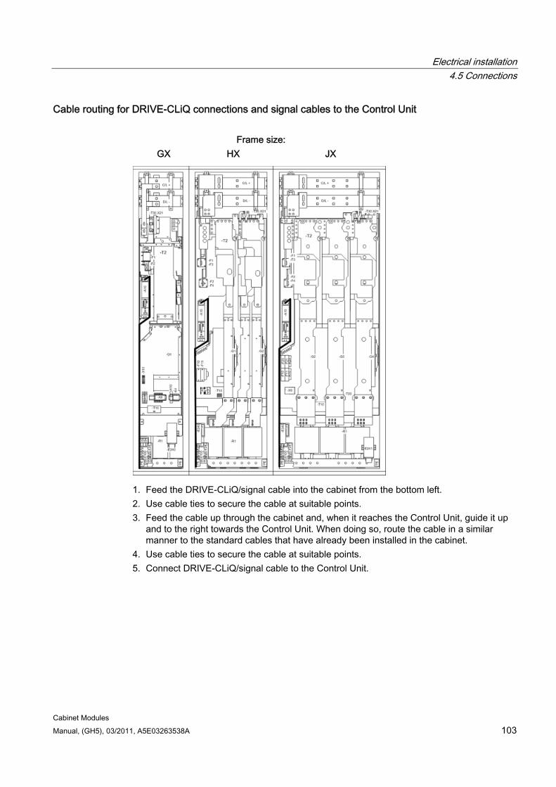
Electrical installation 4.5 Connections
Cabinet Modules Manual, (GH5), 03/2011, A5E03263538A 103
Cable routing for DRIVE-CLiQ connections and signal cables to the Control Unit
Frame size: GX HX JX
1. Feed the DRIVE-CLiQ/signal cable into the cabinet from the bottom left. 2. Use cable ties to secure the cable at suitable points. 3. Feed the cable up through the cabinet and, when it reaches the Control Unit, guide it up
and to the right towards the Control Unit. When doing so, route the cable in a similar manner to the standard cables that have already been installed in the cabinet.
4. Use cable ties to secure the cable at suitable points. 5. Connect DRIVE-CLiQ/signal cable to the Control Unit.
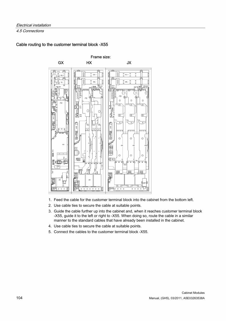
Electrical installation 4.5 Connections
Cabinet Modules 104 Manual, (GH5), 03/2011, A5E03263538A
Cable routing to the customer terminal block -X55
Frame size: GX HX JX
1. Feed the cable for the customer terminal block into the cabinet from the bottom left. 2. Use cable ties to secure the cable at suitable points. 3. Guide the cable further up into the cabinet and, when it reaches customer terminal block
-X55, guide it to the left or right to -X55. When doing so, route the cable in a similar manner to the standard cables that have already been installed in the cabinet.
4. Use cable ties to secure the cable at suitable points. 5. Connect the cables to the customer terminal block -X55.
Electrical installation 4.5 Connections
Cabinet Modules Manual, (GH5), 03/2011, A5E03263538A 105
4.5.11.5 Cable routing for Active Line Modules For the Active Line Modules, the customer must carry out the following cabling or connection work:
Table 4- 16 Checklist for cabling or connection work for Active Line Modules
Cable routing Completed? PROFIBUS cable or PROFINET cable to the Control Unit DRIVE-CLiQ connections / signal cables to the Control Unit Signal cables to the customer terminal block –X55 Notice: The "Basic rules for cable routing" and "Preparatory steps" described above must be observed whenever any cabling or connection work is performed!
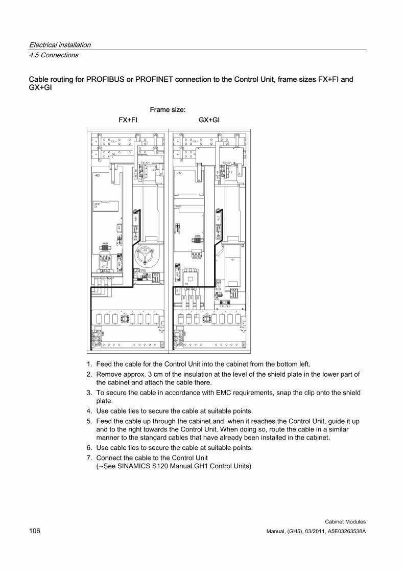
Electrical installation 4.5 Connections
Cabinet Modules 106 Manual, (GH5), 03/2011, A5E03263538A
Cable routing for PROFIBUS or PROFINET connection to the Control Unit, frame sizes FX+FI and GX+GI
Frame size:
FX+FI GX+GI
1. Feed the cable for the Control Unit into the cabinet from the bottom left. 2. Remove approx. 3 cm of the insulation at the level of the shield plate in the lower part of
the cabinet and attach the cable there. 3. To secure the cable in accordance with EMC requirements, snap the clip onto the shield
plate. 4. Use cable ties to secure the cable at suitable points. 5. Feed the cable up through the cabinet and, when it reaches the Control Unit, guide it up
and to the right towards the Control Unit. When doing so, route the cable in a similar manner to the standard cables that have already been installed in the cabinet.
6. Use cable ties to secure the cable at suitable points. 7. Connect the cable to the Control Unit
(→See SINAMICS S120 Manual GH1 Control Units)
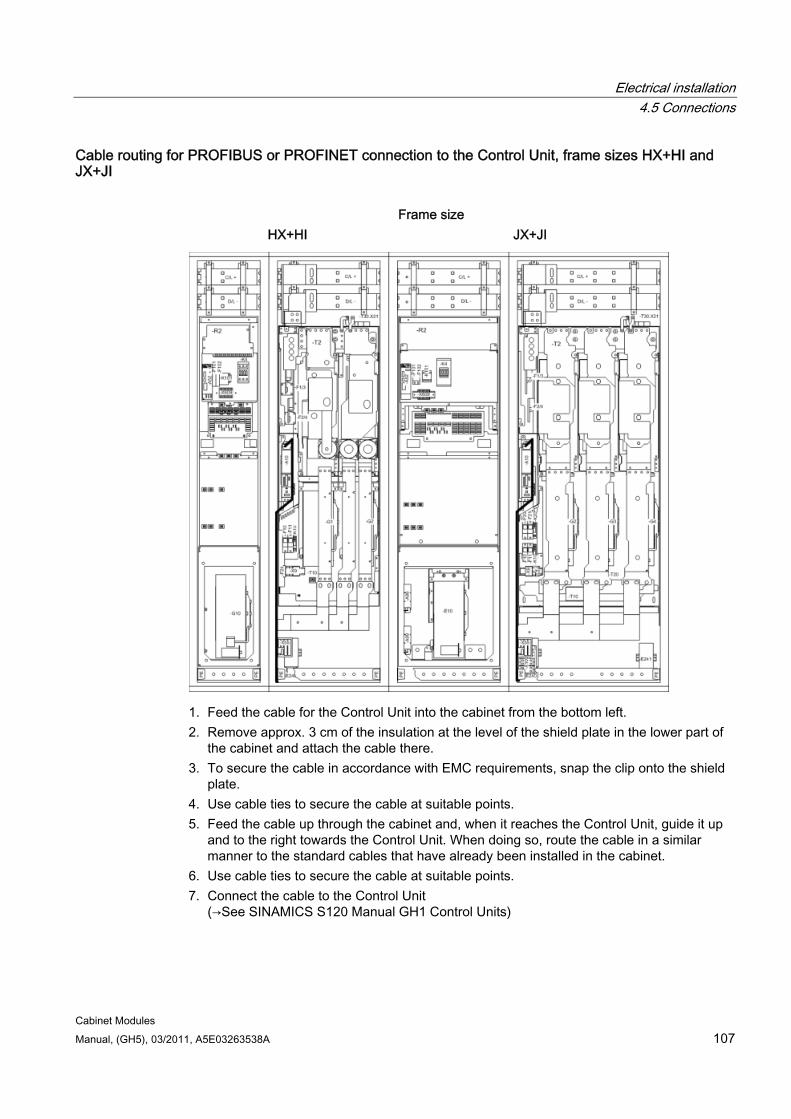
Electrical installation 4.5 Connections
Cabinet Modules Manual, (GH5), 03/2011, A5E03263538A 107
Cable routing for PROFIBUS or PROFINET connection to the Control Unit, frame sizes HX+HI and JX+JI
Frame size
HX+HI JX+JI
1. Feed the cable for the Control Unit into the cabinet from the bottom left. 2. Remove approx. 3 cm of the insulation at the level of the shield plate in the lower part of
the cabinet and attach the cable there. 3. To secure the cable in accordance with EMC requirements, snap the clip onto the shield
plate. 4. Use cable ties to secure the cable at suitable points. 5. Feed the cable up through the cabinet and, when it reaches the Control Unit, guide it up
and to the right towards the Control Unit. When doing so, route the cable in a similar manner to the standard cables that have already been installed in the cabinet.
6. Use cable ties to secure the cable at suitable points. 7. Connect the cable to the Control Unit
(→See SINAMICS S120 Manual GH1 Control Units)
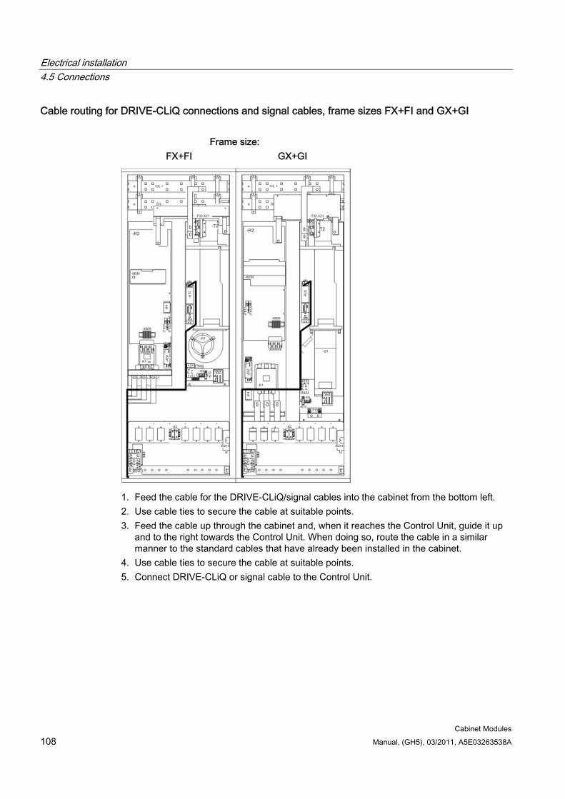
Electrical installation 4.5 Connections
Cabinet Modules 108 Manual, (GH5), 03/2011, A5E03263538A
Cable routing for DRIVE-CLiQ connections and signal cables, frame sizes FX+FI and GX+GI
Frame size: FX+FI GX+GI
1. Feed the cable for the DRIVE-CLiQ/signal cables into the cabinet from the bottom left. 2. Use cable ties to secure the cable at suitable points. 3. Feed the cable up through the cabinet and, when it reaches the Control Unit, guide it up
and to the right towards the Control Unit. When doing so, route the cable in a similar manner to the standard cables that have already been installed in the cabinet.
4. Use cable ties to secure the cable at suitable points. 5. Connect DRIVE-CLiQ or signal cable to the Control Unit.
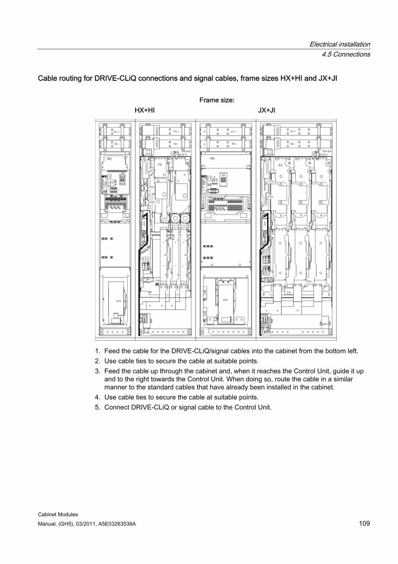
Electrical installation 4.5 Connections
Cabinet Modules Manual, (GH5), 03/2011, A5E03263538A 109
Cable routing for DRIVE-CLiQ connections and signal cables, frame sizes HX+HI and JX+JI
Frame size: HX+HI JX+JI
1. Feed the cable for the DRIVE-CLiQ/signal cables into the cabinet from the bottom left. 2. Use cable ties to secure the cable at suitable points. 3. Feed the cable up through the cabinet and, when it reaches the Control Unit, guide it up
and to the right towards the Control Unit. When doing so, route the cable in a similar manner to the standard cables that have already been installed in the cabinet.
4. Use cable ties to secure the cable at suitable points. 5. Connect DRIVE-CLiQ or signal cable to the Control Unit.
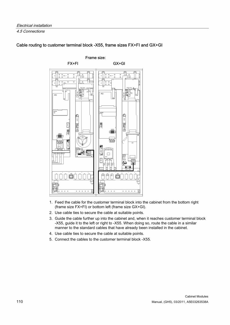
Electrical installation 4.5 Connections
Cabinet Modules 110 Manual, (GH5), 03/2011, A5E03263538A
Cable routing to customer terminal block -X55, frame sizes FX+FI and GX+GI
Frame size: FX+FI GX+GI
1. Feed the cable for the customer terminal block into the cabinet from the bottom right (frame size FX+FI) or bottom left (frame size GX+GI).
2. Use cable ties to secure the cable at suitable points. 3. Guide the cable further up into the cabinet and, when it reaches customer terminal block
-X55, guide it to the left or right to -X55. When doing so, route the cable in a similar manner to the standard cables that have already been installed in the cabinet.
4. Use cable ties to secure the cable at suitable points. 5. Connect the cables to the customer terminal block -X55.
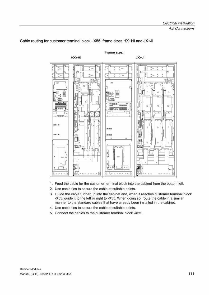
Electrical installation 4.5 Connections
Cabinet Modules Manual, (GH5), 03/2011, A5E03263538A 111
Cable routing for customer terminal block –X55, frame sizes HX+HI and JX+JI
Frame size: HX+HI JX+JI
1. Feed the cable for the customer terminal block into the cabinet from the bottom left. 2. Use cable ties to secure the cable at suitable points. 3. Guide the cable further up into the cabinet and, when it reaches customer terminal block
-X55, guide it to the left or right to -X55. When doing so, route the cable in a similar manner to the standard cables that have already been installed in the cabinet.
4. Use cable ties to secure the cable at suitable points. 5. Connect the cables to the customer terminal block -X55.
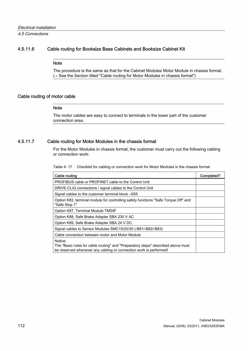
Electrical installation 4.5 Connections
Cabinet Modules 112 Manual, (GH5), 03/2011, A5E03263538A
4.5.11.6 Cable routing for Booksize Base Cabinets and Booksize Cabinet Kit
Note
The procedure is the same as that for the Cabinet Modules Motor Module in chassis format.(→ See the Section titled "Cable routing for Motor Modules in chassis format")
Cable routing of motor cable
Note
The motor cables are easy to connect to terminals in the lower part of the customer connection area.
4.5.11.7 Cable routing for Motor Modules in the chassis format For the Motor Modules in chassis format, the customer must carry out the following cabling or connection work:
Table 4- 17 Checklist for cabling or connection work for Motor Modules in the chassis format
Cable routing Completed? PROFIBUS cable or PROFINET cable to the Control Unit DRIVE-CLiQ connections / signal cables to the Control Unit Signal cables to the customer terminal block –X55 Option K82, terminal module for controlling safety functions "Safe Torque Off" and "Safe Stop 1"
Option K87, Terminal Module TM54F Option K88, Safe Brake Adapter SBA 230 V AC Option K89, Safe Brake Adapter SBA 24 V DC Signal cables to Sensor Modules SMC10/20/30 (-B81/-B82/-B83) Cable connection between motor and Motor Module Notice: The "Basic rules for cable routing" and "Preparatory steps" described above must be observed whenever any cabling or connection work is performed!
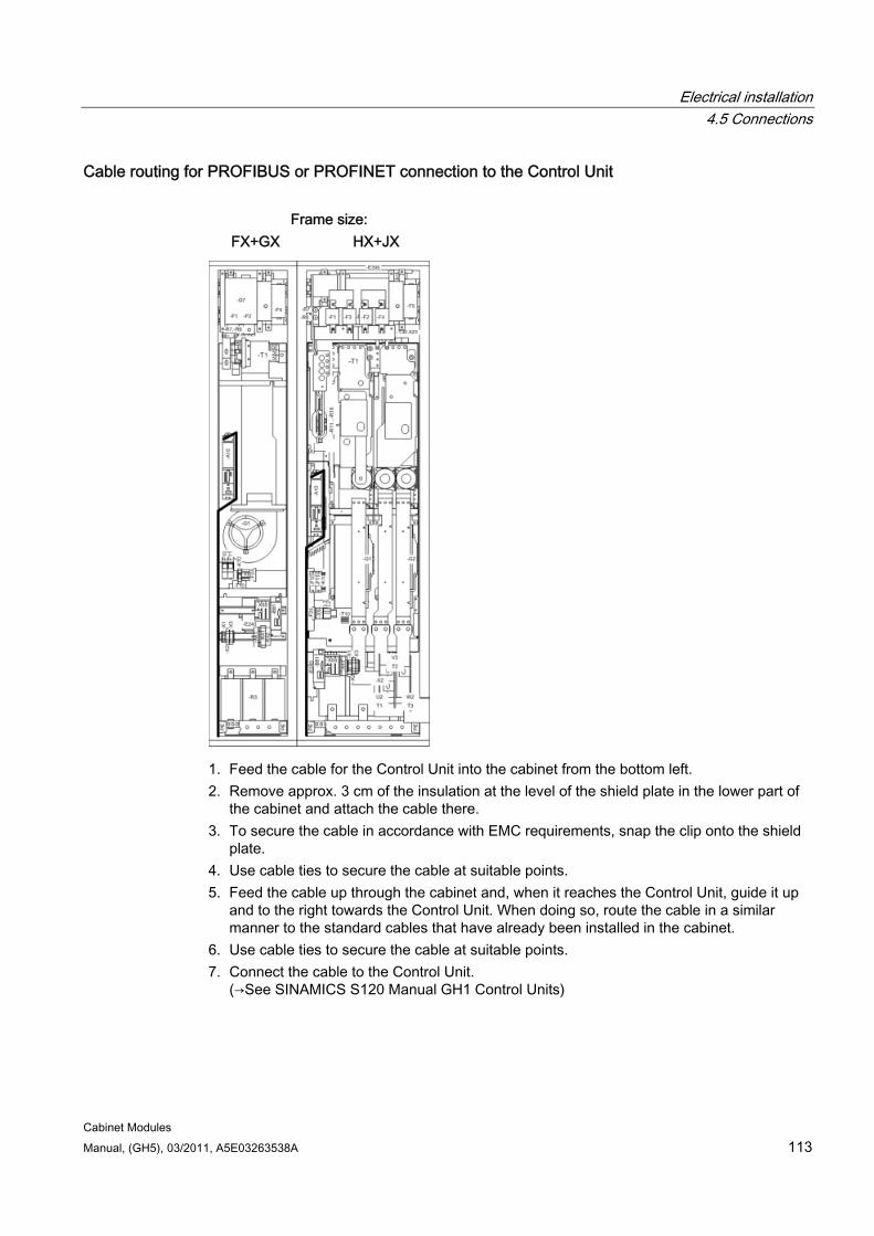
Electrical installation 4.5 Connections
Cabinet Modules Manual, (GH5), 03/2011, A5E03263538A 113
Cable routing for PROFIBUS or PROFINET connection to the Control Unit
Frame size: FX+GX HX+JX
1. Feed the cable for the Control Unit into the cabinet from the bottom left. 2. Remove approx. 3 cm of the insulation at the level of the shield plate in the lower part of
the cabinet and attach the cable there. 3. To secure the cable in accordance with EMC requirements, snap the clip onto the shield
plate. 4. Use cable ties to secure the cable at suitable points. 5. Feed the cable up through the cabinet and, when it reaches the Control Unit, guide it up
and to the right towards the Control Unit. When doing so, route the cable in a similar manner to the standard cables that have already been installed in the cabinet.
6. Use cable ties to secure the cable at suitable points. 7. Connect the cable to the Control Unit.
(→See SINAMICS S120 Manual GH1 Control Units)
Electrical installation 4.5 Connections
Cabinet Modules 114 Manual, (GH5), 03/2011, A5E03263538A
Cable routing for DRIVE-CLiQ connections and signal cables to the Control Unit
Frame size: FX+GX HX+JX
1. Feed the DRIVE-CLiQ/signal cable into the cabinet from the bottom left. 2. Use cable ties to secure the cable at suitable points. 3. Feed the cable up through the cabinet and, when it reaches the Control Unit, guide it up
and to the right towards the Control Unit. When doing so, route the cable in a similar manner to the standard cables that have already been installed in the cabinet.
4. Use cable ties to secure the cable at suitable points. 5. Connect DRIVE-CLiQ/signal cable to the Control Unit.
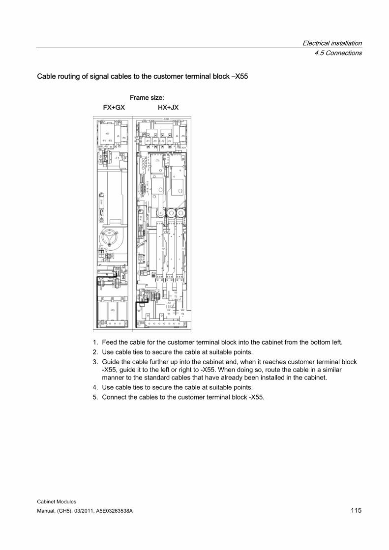
Electrical installation 4.5 Connections
Cabinet Modules Manual, (GH5), 03/2011, A5E03263538A 115
Cable routing of signal cables to the customer terminal block –X55
Frame size: FX+GX HX+JX
1. Feed the cable for the customer terminal block into the cabinet from the bottom left. 2. Use cable ties to secure the cable at suitable points. 3. Guide the cable further up into the cabinet and, when it reaches customer terminal block
-X55, guide it to the left or right to -X55. When doing so, route the cable in a similar manner to the standard cables that have already been installed in the cabinet.
4. Use cable ties to secure the cable at suitable points. 5. Connect the cables to the customer terminal block -X55.
Electrical installation 4.5 Connections
Cabinet Modules 116 Manual, (GH5), 03/2011, A5E03263538A
Cable routing for the "Safe Torque off" and “Safe Stop 1” functions
Note
The procedure is the same as that for the customer terminal block.
Connect the cable to the terminals to control the functions.
(→ See the chapter titled "Options", section "K82, terminal module for activating "Safe Torque Off" and "Safe Stop 1"")
Cable routing for the Terminal Module TM54F
Note
The procedure is the same as that for the customer terminal block.
Connect the cable to the terminals to control the functions.
(→ see Chapter "Options" in Section "K87, Terminal Module TM54F")
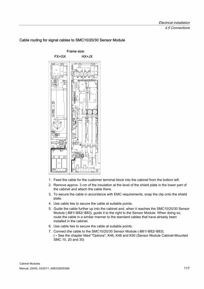
Electrical installation 4.5 Connections
Cabinet Modules Manual, (GH5), 03/2011, A5E03263538A 117
Cable routing for signal cables to SMC10/20/30 Sensor Module
Frame size: FX+GX HX+JX
1. Feed the cable for the customer terminal block into the cabinet from the bottom left. 2. Remove approx. 3 cm of the insulation at the level of the shield plate in the lower part of
the cabinet and attach the cable there. 3. To secure the cable in accordance with EMC requirements, snap the clip onto the shield
plate. 4. Use cable ties to secure the cable at suitable points. 5. Guide the cable further up into the cabinet and, when it reaches the SMC10/20/30 Sensor
Module (-B81/-B82/-B83), guide it to the right to the Sensor Module. When doing so, route the cable in a similar manner to the standard cables that have already been installed in the cabinet.
6. Use cable ties to secure the cable at suitable points. 7. Connect the cable to the SMC10/20/30 Sensor Module (-B81/-B82/-B83).
(→ See the chapter titled "Options", K46, K48 and K50 (Sensor Module Cabinet-Mounted SMC 10, 20 and 30)
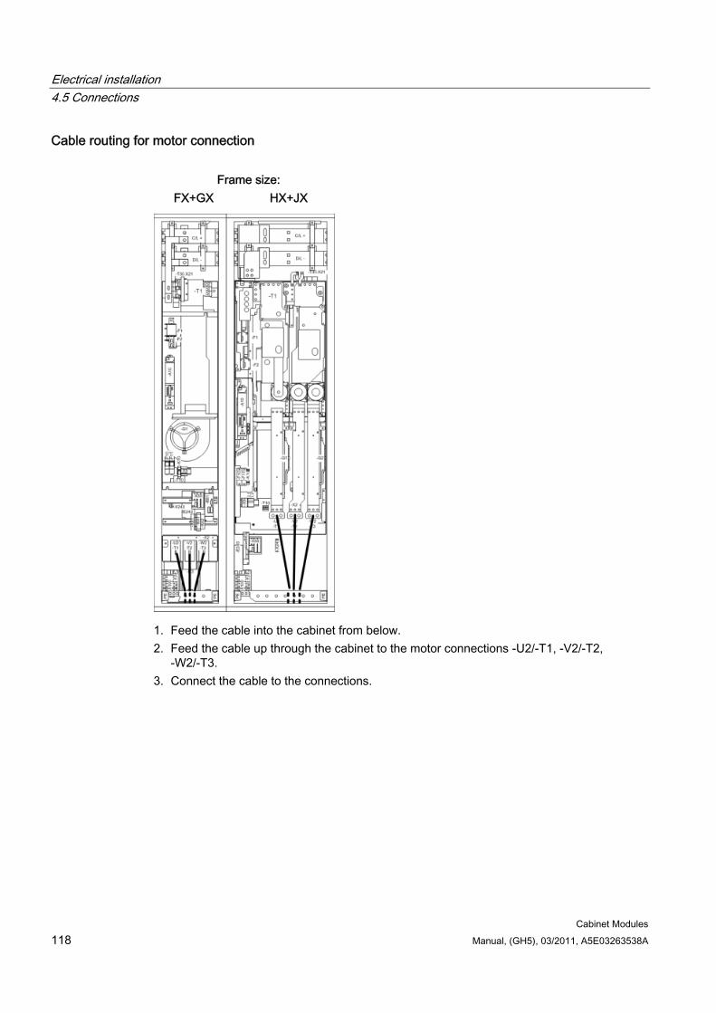
Electrical installation 4.5 Connections
Cabinet Modules 118 Manual, (GH5), 03/2011, A5E03263538A
Cable routing for motor connection
Frame size: FX+GX HX+JX
1. Feed the cable into the cabinet from below. 2. Feed the cable up through the cabinet to the motor connections -U2/-T1, -V2/-T2,
-W2/-T3. 3. Connect the cable to the connections.
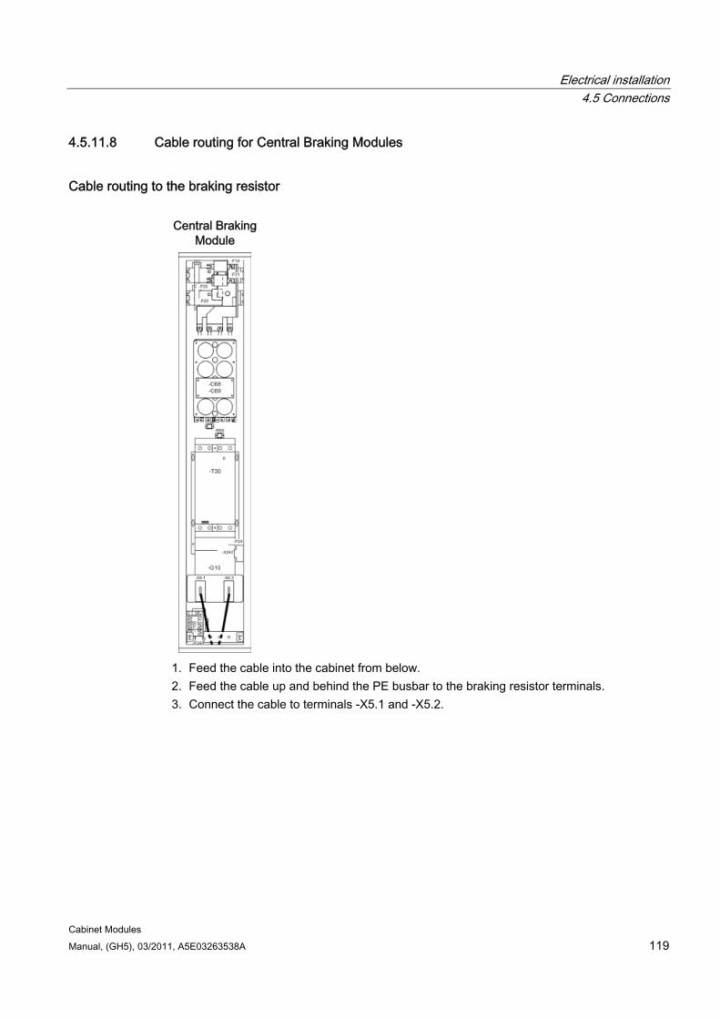
Electrical installation 4.5 Connections
Cabinet Modules Manual, (GH5), 03/2011, A5E03263538A 119
4.5.11.8 Cable routing for Central Braking Modules
Cable routing to the braking resistor Central Braking
Module
1. Feed the cable into the cabinet from below. 2. Feed the cable up and behind the PE busbar to the braking resistor terminals. 3. Connect the cable to terminals -X5.1 and -X5.2.
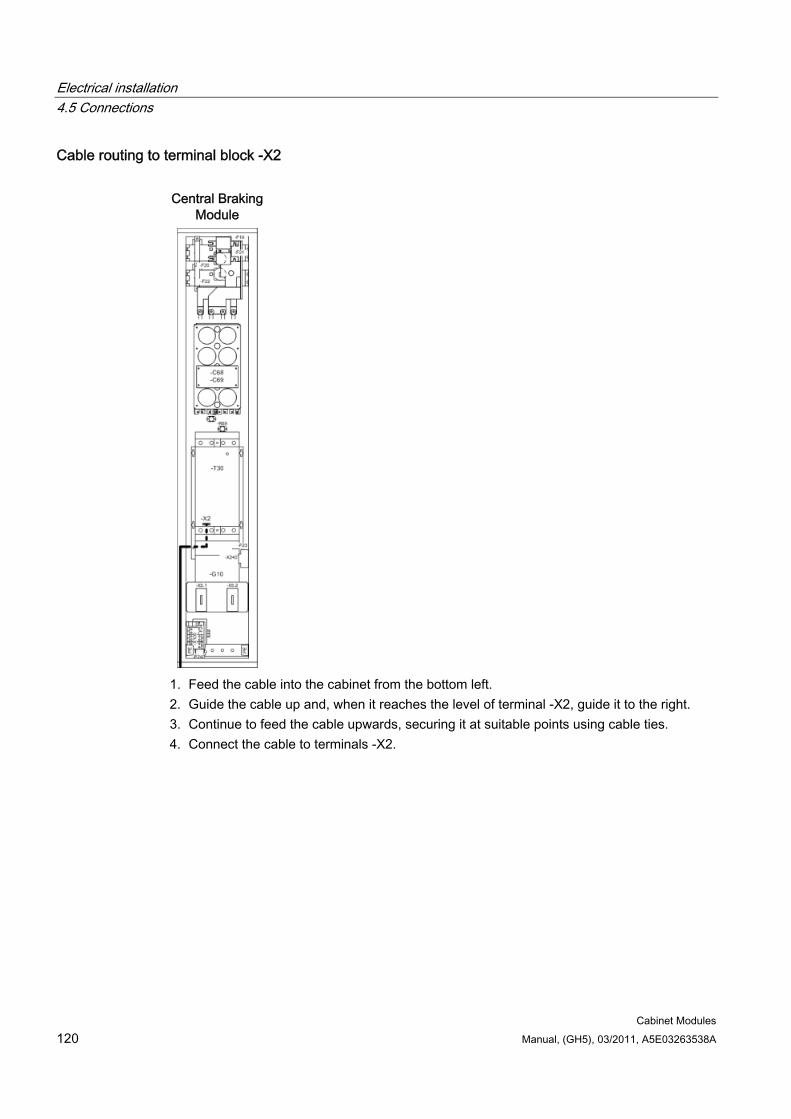
Electrical installation 4.5 Connections
Cabinet Modules 120 Manual, (GH5), 03/2011, A5E03263538A
Cable routing to terminal block -X2 Central Braking
Module
1. Feed the cable into the cabinet from the bottom left. 2. Guide the cable up and, when it reaches the level of terminal -X2, guide it to the right. 3. Continue to feed the cable upwards, securing it at suitable points using cable ties. 4. Connect the cable to terminals -X2.
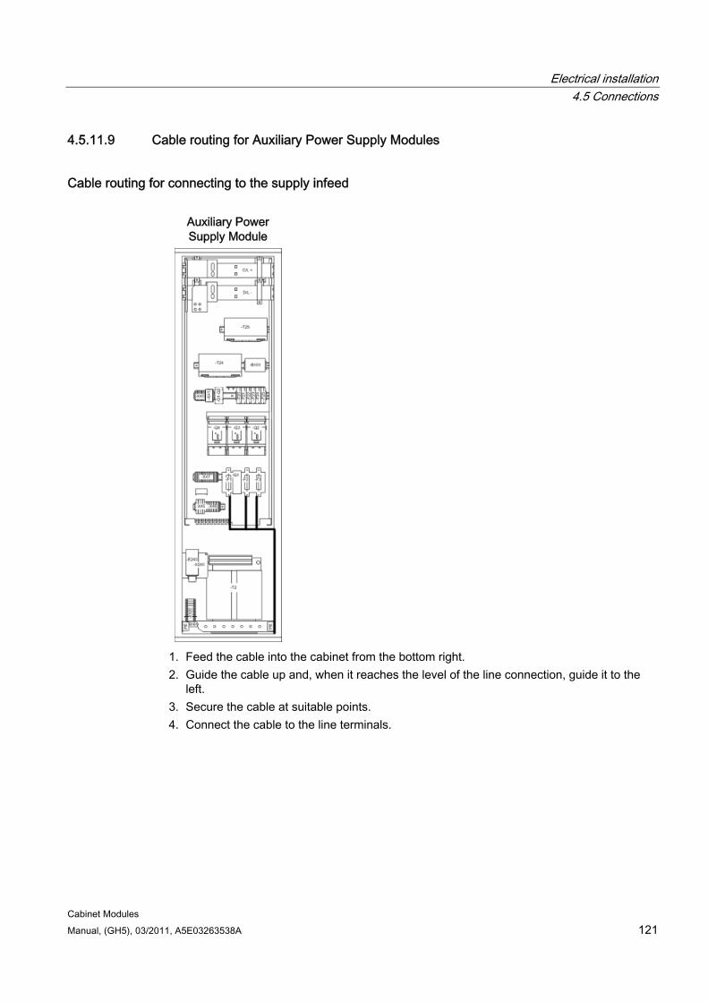
Electrical installation 4.5 Connections
Cabinet Modules Manual, (GH5), 03/2011, A5E03263538A 121
4.5.11.9 Cable routing for Auxiliary Power Supply Modules
Cable routing for connecting to the supply infeed
Auxiliary Power Supply Module
1. Feed the cable into the cabinet from the bottom right. 2. Guide the cable up and, when it reaches the level of the line connection, guide it to the
left. 3. Secure the cable at suitable points. 4. Connect the cable to the line terminals.
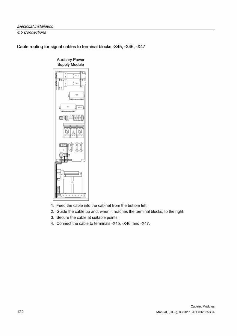
Electrical installation 4.5 Connections
Cabinet Modules 122 Manual, (GH5), 03/2011, A5E03263538A
Cable routing for signal cables to terminal blocks -X45, -X46, -X47
Auxiliary Power Supply Module
1. Feed the cable into the cabinet from the bottom left. 2. Guide the cable up and, when it reaches the terminal blocks, to the right. 3. Secure the cable at suitable points. 4. Connect the cable to terminals -X45, -X46, and -X47.
Cabinet Modules Manual, (GH5), 03/2011, A5E03263538A 123
Cabinet Modules 55.1 Line Connection Modules
5.1.1 General information
DANGER
Hazardous voltages are present in certain parts of this equipment during operation of the cabinet unit. Only qualified personnel may work on the cabinet. Such personnel must be thoroughly familiar with all the warnings and maintenance procedures for the cabinet described in the documentation provided.
The successful and safe operation of this cabinet is dependent on correct transport, proper storage and installation, as well as careful operation and maintenance. National safety regulations must be observed.
Cabinet Modules 5.1 Line Connection Modules
Cabinet Modules 124 Manual, (GH5), 03/2011, A5E03263538A
5.1.2 Description
Note
Refer to the layout diagrams and circuit diagrams provided on the customer DVD supplied with the device for the arrangement of components and interfaces, and for wiring.
Power is fed to the drive line-up via Line Modules, which generate a DC voltage from the line voltage and, therefore, supply energy to the Motor Modules connected to the DC link. They are suitable for connection to systems grounded at the neutral point (TN, TT) and non-grounded (IT) systems. The Line Modules are connected to the incoming supply via Line Connection Modules and are equipped with a radio interference suppression filter in accordance with EN 61800-3, Category C3 as a standard feature.
Line Connection Modules contain the line-side infeed with main breaker and fuse switch disconnector or circuit breaker and provide the connection between the plant power system and the Line Modules.
Line Connection Modules are available for the following voltages and currents:
Input voltage Input current 380 to 480 V AC, 3-phase 250 ... 3200 A 500 to 690 V AC, 3-phase 280 ... 3200 A
Table 5- 1 X1 terminals for the supply infeed
Terminals Technical specifications U1/L1, V1/L2, W1/L3 3 AC power input
Voltage: 380 V AC, 3-phase –10 % to 480 V AC, 3-phase +10 % (-15 % < 1 min) 500 V AC, 3-phase –10 % to 690 V AC, 3-phase +10 % (-15 % < 1 min) Frequency: 47 ... 63 Hz
Depending on the input current, the following designs are used:
≤ 800 A: Main breaker with fuse switch disconnector
> 800 A: Circuit breaker, type 3WL, with option L25 as draw-out circuit breaker
Configuration
Note
The configuration examples of the individual Line Connection Modules are used to illustrate the positioning of the factory-fitted components. They show the maximum possible configuration of the modules, which contain all options that can be ordered.
Refer to the layout diagrams (AO) on the customer DVD for the precise order-specific location of the components.
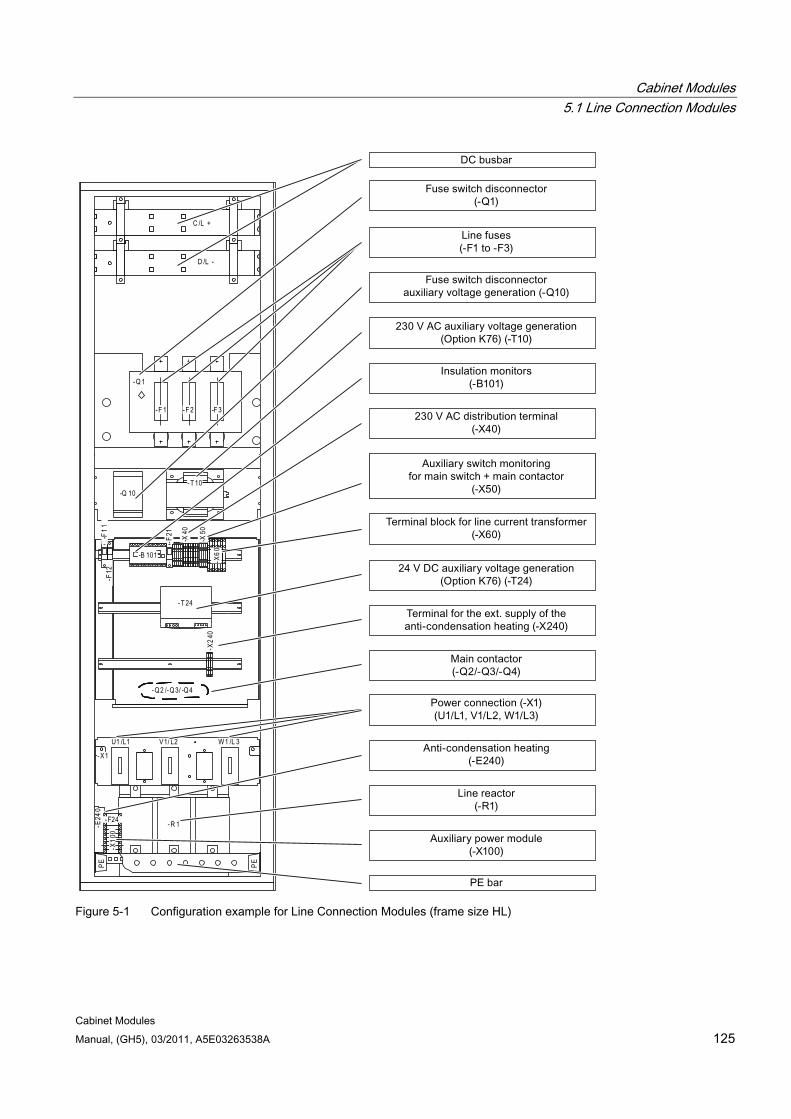
Cabinet Modules 5.1 Line Connection Modules
Cabinet Modules Manual, (GH5), 03/2011, A5E03263538A 125
C /L +
D /L -
-R 1
-Q1
-F 1 -F 3-F 2
-T 10
D udt_ F _X 2-X1
V1/ L2U1 /L1 W1 /L 3
-X60
-X50
-X40
-F21
-B 101
-F11
-F12
- T 24
-X24
0
-Q2 /-Q3/ -Q4
-E24
0
-X10
0
- F24
-Q 10
PE PE
Figure 5-1 Configuration example for Line Connection Modules (frame size HL)
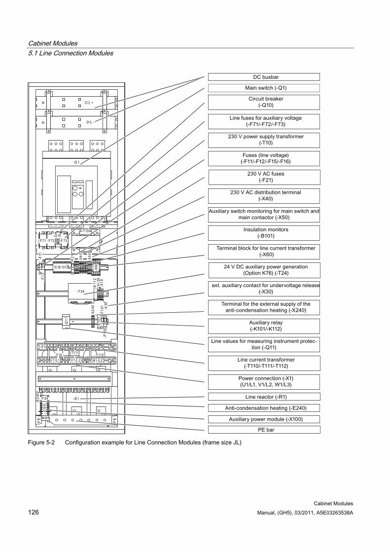
Cabinet Modules 5.1 Line Connection Modules
Cabinet Modules 126 Manual, (GH5), 03/2011, A5E03263538A
C/ L +
D /L -
-R 1
-Q 1
-Q10-F 71 -F 73-F 72
-T 10
-T111-T 10 -T 112W1 /L3V1 /L 2U 1 /L1
-X1
-E24
0
-X10
0
-F 24
-X60
-X50
-F21
-B 101
-F11
-F12
- T 24
-K11
2-X
120
-X19
-X30
-F10
1-F
102
-K10
1-X
240
-Q11
PE
PE
-X40
Figure 5-2 Configuration example for Line Connection Modules (frame size JL)
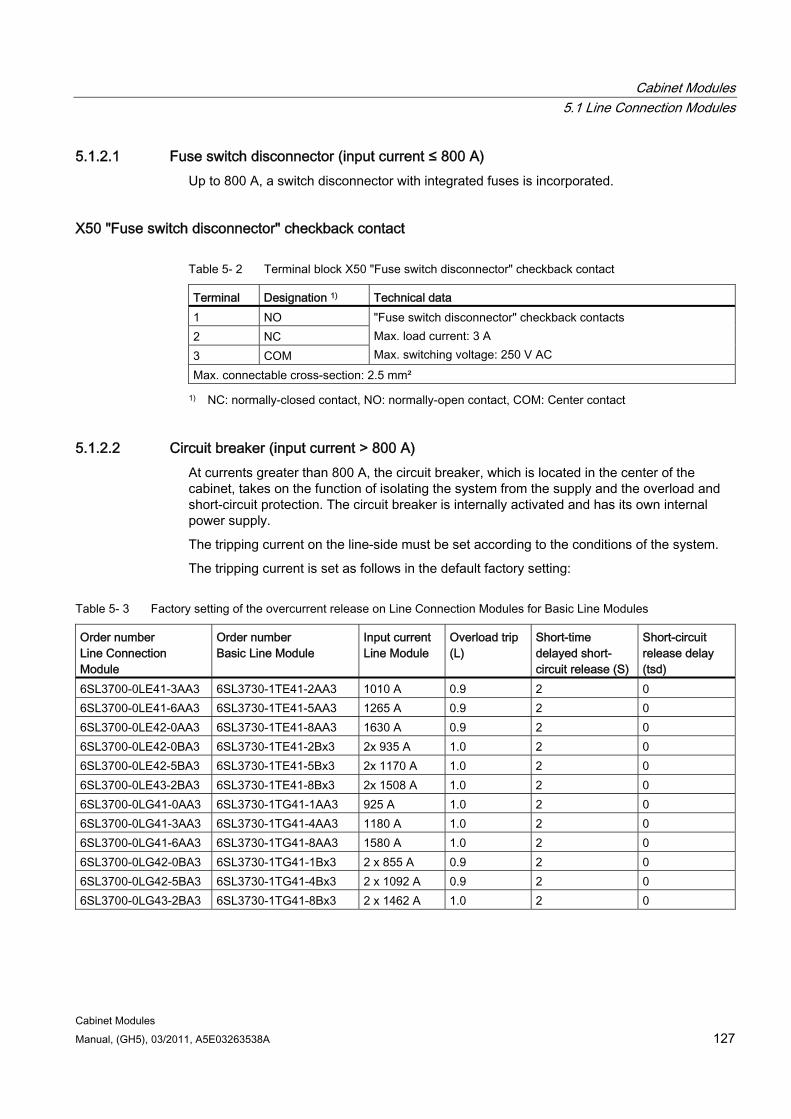
Cabinet Modules 5.1 Line Connection Modules
Cabinet Modules Manual, (GH5), 03/2011, A5E03263538A 127
5.1.2.1 Fuse switch disconnector (input current ≤ 800 A) Up to 800 A, a switch disconnector with integrated fuses is incorporated.
X50 "Fuse switch disconnector" checkback contact
Table 5- 2 Terminal block X50 "Fuse switch disconnector" checkback contact
Terminal Designation 1) Technical data 1 NO 2 NC 3 COM
"Fuse switch disconnector" checkback contacts Max. load current: 3 A Max. switching voltage: 250 V AC
Max. connectable cross-section: 2.5 mm²
1) NC: normally-closed contact, NO: normally-open contact, COM: Center contact
5.1.2.2 Circuit breaker (input current > 800 A) At currents greater than 800 A, the circuit breaker, which is located in the center of the cabinet, takes on the function of isolating the system from the supply and the overload and short-circuit protection. The circuit breaker is internally activated and has its own internal power supply.
The tripping current on the line-side must be set according to the conditions of the system.
The tripping current is set as follows in the default factory setting:
Table 5- 3 Factory setting of the overcurrent release on Line Connection Modules for Basic Line Modules
Order number Line Connection Module
Order number Basic Line Module
Input current Line Module
Overload trip (L)
Short-time delayed short-circuit release (S)
Short-circuit release delay (tsd)
6SL3700-0LE41-3AA3 6SL3730-1TE41-2AA3 1010 A 0.9 2 0 6SL3700-0LE41-6AA3 6SL3730-1TE41-5AA3 1265 A 0.9 2 0 6SL3700-0LE42-0AA3 6SL3730-1TE41-8AA3 1630 A 0.9 2 0 6SL3700-0LE42-0BA3 6SL3730-1TE41-2Bx3 2x 935 A 1.0 2 0 6SL3700-0LE42-5BA3 6SL3730-1TE41-5Bx3 2x 1170 A 1.0 2 0 6SL3700-0LE43-2BA3 6SL3730-1TE41-8Bx3 2x 1508 A 1.0 2 0 6SL3700-0LG41-0AA3 6SL3730-1TG41-1AA3 925 A 1.0 2 0 6SL3700-0LG41-3AA3 6SL3730-1TG41-4AA3 1180 A 1.0 2 0 6SL3700-0LG41-6AA3 6SL3730-1TG41-8AA3 1580 A 1.0 2 0 6SL3700-0LG42-0BA3 6SL3730-1TG41-1Bx3 2 x 855 A 0.9 2 0 6SL3700-0LG42-5BA3 6SL3730-1TG41-4Bx3 2 x 1092 A 0.9 2 0 6SL3700-0LG43-2BA3 6SL3730-1TG41-8Bx3 2 x 1462 A 1.0 2 0
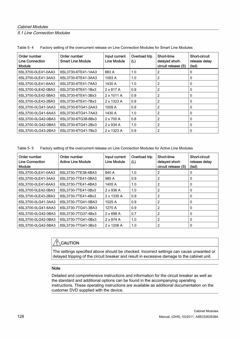
Cabinet Modules 5.1 Line Connection Modules
Cabinet Modules 128 Manual, (GH5), 03/2011, A5E03263538A
Table 5- 4 Factory setting of the overcurrent release on Line Connection Modules for Smart Line Modules
Order number Line Connection Module
Order number Smart Line Module
Input current Line Module
Overload trip (L)
Short-time delayed short-circuit release (S)
Short-circuit release delay (tsd)
6SL3700-0LE41-0AA3 6SL3730-6TE41-1AA3 883 A 1.0 2 0 6SL3700-0LE41-3AA3 6SL3730-6TE41-3AA3 1093 A 1.0 2 0 6SL3700-0LE41-6AA3 6SL3730-6TE41-7AA3 1430 A 1.0 2 0 6SL3700-0LE42-0BA3 6SL3730-6TE41-1Bx3 2 x 817 A 0.9 2 0 6SL3700-0LE42-5BA3 6SL3730-6TE41-3Bx3 2 x 10¹¹ A 0.9 2 0 6SL3700-0LE43-2BA3 6SL3730-6TE41-7Bx3 2 x 1323 A 0.9 2 0 6SL3700-0LG41-3AA3 6SL3730-6TG41-2AA3 1009 A 0.9 2 0 6SL3700-0LG41-6AA3 6SL3730-6TG41-7AA3 1430 A 1.0 2 0 6SL3700-0LG42-0BA3 6SL3730-6TG38-8Bx3 2 x 700 A 0.8 2 0 6SL3700-0LG42-0BA3 6SL3730-6TG41-2Bx3 2 x 934 A 1.0 2 0 6SL3700-0LG43-2BA3 6SL3730-6TG41-7Bx3 2 x 1323 A 0.9 2 0
Table 5- 5 Factory setting of the overcurrent release on Line Connection Modules for Active Line Modules
Order number Line Connection Module
Order number Active Line Module
Input current Line Module
Overload trip (L)
Short-time delayed short-circuit release (S)
Short-circuit release delay (tsd)
6SL3700-0LE41-0AA3 6SL3730-7TE38-4BA3 840 A 1.0 2 0 6SL3700-0LE41-3AA3 6SL3730-7TE41-0BA3 985 A 0.9 2 0 6SL3700-0LE41-6AA3 6SL3730-7TE41-4BA3 1405 A 1.0 2 0 6SL3700-0LE42-0BA3 6SL3730-7TE41-0Bx3 2 x 936 A 1.0 2 0 6SL3700-0LE43-2BA3 6SL3730-7TE41-4Bx3 2 x 1335 A 0.9 2 0 6SL3700-0LG41-3AA3 6SL3730-7TG41-0BA3 1025 A 0.9 2 0 6SL3700-0LG41-6AA3 6SL3730-7TG41-3BA3 1270 A 0.9 2 0 6SL3700-0LG42-0BA3 6SL3730-7TG37-4Bx3 2 x 698 A 0.7 2 0 6SL3700-0LG42-0BA3 6SL3730-7TG41-0Bx3 2 x 974 A 1.0 2 0 6SL3700-0LG42-5BA3 6SL3730-7TG41-3Bx3 2 x 1206 A 1.0 2 0
CAUTION The settings specified above should be checked. Incorrect settings can cause unwanted or delayed tripping of the circuit breaker and result in excessive damage to the cabinet unit.
Note
Detailed and comprehensive instructions and information for the circuit breaker as well as the standard and additional options can be found in the accompanying operating instructions, These operating instructions are available as additional documentation on the customer DVD supplied with the device.
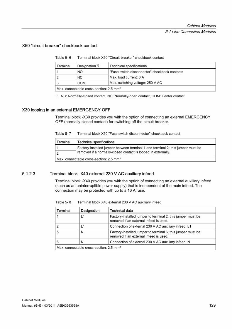
Cabinet Modules 5.1 Line Connection Modules
Cabinet Modules Manual, (GH5), 03/2011, A5E03263538A 129
X50 "circuit breaker" checkback contact
Table 5- 6 Terminal block X50 "Circuit-breaker" checkback contact
Terminal Designation 1) Technical specifications 1 NO 2 NC 3 COM
"Fuse switch disconnector" checkback contacts Max. load current: 3 A Max. switching voltage: 250 V AC
Max. connectable cross-section: 2.5 mm²
1) NC: Normally-closed contact, NO: Normally-open contact, COM: Center contact
X30 looping in an external EMERGENCY OFF Terminal block -X30 provides you with the option of connecting an external EMERGENCY OFF (normally-closed contact) for switching off the circuit breaker.
Table 5- 7 Terminal block X30 "Fuse switch disconnector" checkback contact
Terminal Technical specifications 1 2
Factory-installed jumper between terminal 1 and terminal 2; this jumper must be removed if a normally-closed contact is looped in externally.
Max. connectable cross-section: 2.5 mm2
5.1.2.3 Terminal block -X40 external 230 V AC auxiliary infeed Terminal block -X40 provides you with the option of connecting an external auxiliary infeed (such as an uninterruptible power supply) that is independent of the main infeed. The connection may be protected with up to a 16 A fuse.
Table 5- 8 Terminal block X40 external 230 V AC auxiliary infeed
Terminal Designation Technical data 1 L1 Factory-installed jumper to terminal 2; this jumper must be
removed if an external infeed is used. 2 L1 Connection of external 230 V AC auxiliary infeed: L1 5 N Factory-installed jumper to terminal 6; this jumper must be
removed if an external infeed is used. 6 N Connection of external 230 V AC auxiliary infeed: N Max. connectable cross-section: 2.5 mm²
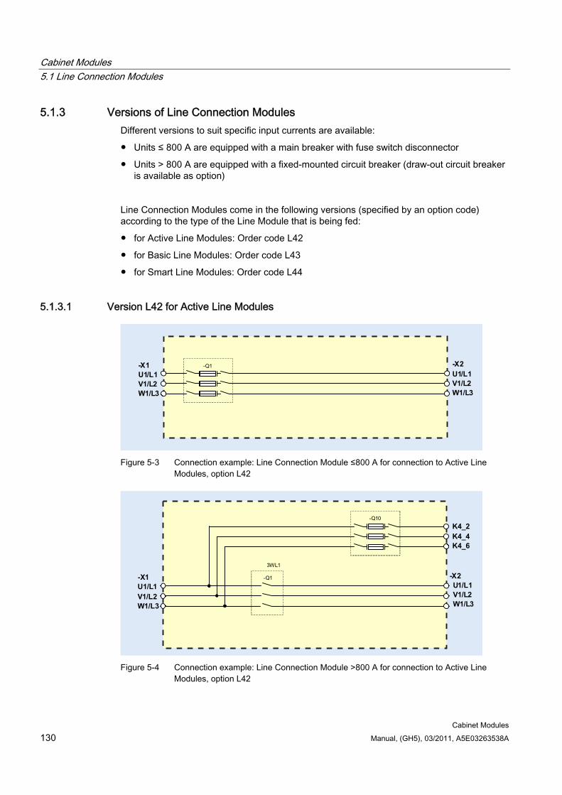
Cabinet Modules 5.1 Line Connection Modules
Cabinet Modules 130 Manual, (GH5), 03/2011, A5E03263538A
5.1.3 Versions of Line Connection Modules Different versions to suit specific input currents are available:
Units ≤ 800 A are equipped with a main breaker with fuse switch disconnector
Units > 800 A are equipped with a fixed-mounted circuit breaker (draw-out circuit breaker is available as option)
Line Connection Modules come in the following versions (specified by an option code) according to the type of the Line Module that is being fed:
for Active Line Modules: Order code L42
for Basic Line Modules: Order code L43
for Smart Line Modules: Order code L44
5.1.3.1 Version L42 for Active Line Modules
-X1U1/L1V1/L2W1/L3
-X2U1/L1V1/L2W1/L3
-Q1
Figure 5-3 Connection example: Line Connection Module ≤800 A for connection to Active Line
Modules, option L42
U1/L1V1/L2W1/L3
-X1U1/L1V1/L2W1/L3
-Q1
3WL1
-X2
-Q10K4_2K4_4K4_6
Figure 5-4 Connection example: Line Connection Module >800 A for connection to Active Line
Modules, option L42
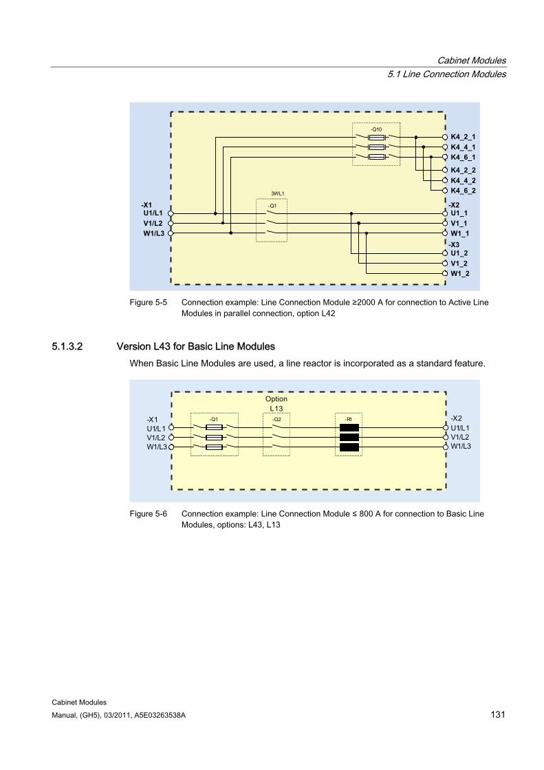
Cabinet Modules 5.1 Line Connection Modules
Cabinet Modules Manual, (GH5), 03/2011, A5E03263538A 131
-Q1
3WL1
-Q10
K4_2_2K4_4_2K4_6_2
K4_2_1K4_4_1K4_6_1
U1_2V1_2W1_2
U1_1-X2
-X3
V1_1W1_1
U1/L1-X1
V1/L2W1/L3
Figure 5-5 Connection example: Line Connection Module ≥2000 A for connection to Active Line
Modules in parallel connection, option L42
5.1.3.2 Version L43 for Basic Line Modules When Basic Line Modules are used, a line reactor is incorporated as a standard feature.
-Q1 -Q2 -R1
Figure 5-6 Connection example: Line Connection Module ≤ 800 A for connection to Basic Line
Modules, options: L43, L13
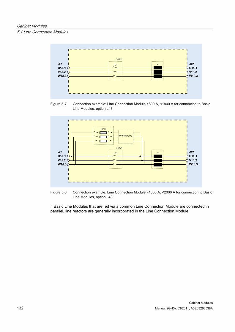
Cabinet Modules 5.1 Line Connection Modules
Cabinet Modules 132 Manual, (GH5), 03/2011, A5E03263538A
-X1U1/L1V1/L2W1/L3
-X2U1/L1V1/L2W1/L3
-Q1
3WL1
-R1
Figure 5-7 Connection example: Line Connection Module >800 A, <1800 A for connection to Basic
Line Modules, option L43
Pre-charging
-X1U1/L1V1/L2W1/L3
-X2U1/L1V1/L2W1/L3
-Q10
-Q1
3WL1
-R1
Figure 5-8 Connection example: Line Connection Module >1800 A, <2000 A for connection to Basic
Line Modules, option L43
If Basic Line Modules that are fed via a common Line Connection Module are connected in parallel, line reactors are generally incorporated in the Line Connection Module.
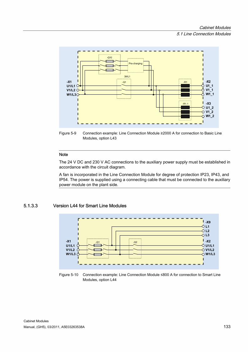
Cabinet Modules 5.1 Line Connection Modules
Cabinet Modules Manual, (GH5), 03/2011, A5E03263538A 133
Pre-charging
-X2U1_1V1_1W1_1
-X1U1/L1V1/L2W1/L3
-Q1 -R1
3WL1
-X3U1_2V1_2W1_2
-R1.1
-Q10
Figure 5-9 Connection example: Line Connection Module ≥2000 A for connection to Basic Line
Modules, option L43
Note
The 24 V DC and 230 V AC connections to the auxiliary power supply must be established in accordance with the circuit diagram.
A fan is incorporated in the Line Connection Module for degree of protection IP23, IP43, and IP54. The power is supplied using a connecting cable that must be connected to the auxiliary power module on the plant side.
5.1.3.3 Version L44 for Smart Line Modules
-X2U1/L1V1/L2W1/L3
-X1U1/L1V1/L2W1/L3
-Q1 -Q2
-X9L1L2L3
Figure 5-10 Connection example: Line Connection Module ≤800 A for connection to Smart Line
Modules, option L44
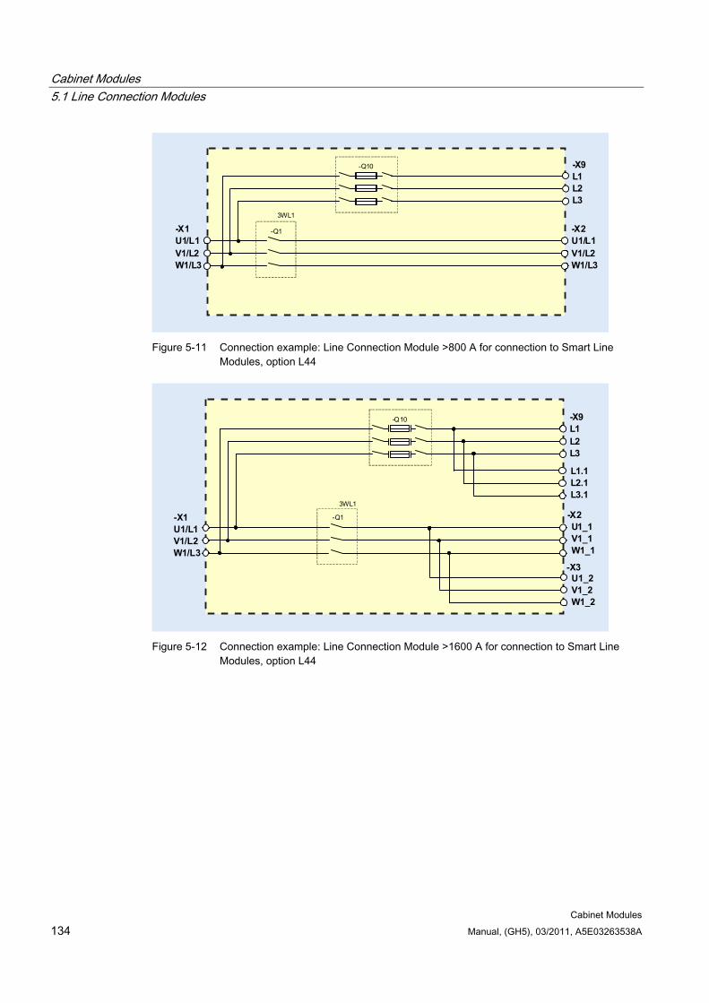
Cabinet Modules 5.1 Line Connection Modules
Cabinet Modules 134 Manual, (GH5), 03/2011, A5E03263538A
-Q1
3WL1
-X1U1/L1V1/L2W1/L3
-Q10
-X2U1/L1V1/L2W1/L3
-X9L1L2L3
Figure 5-11 Connection example: Line Connection Module >800 A for connection to Smart Line
Modules, option L44
U1_1V1_1W1_1
-X1U1/L1V1/L2W1/L3
-Q1
3WL1
-X2
-X3
-Q10 -X9L1L2L3
U1_2V1_2W1_2
L1.1L2.1L3.1
Figure 5-12 Connection example: Line Connection Module >1600 A for connection to Smart Line
Modules, option L44
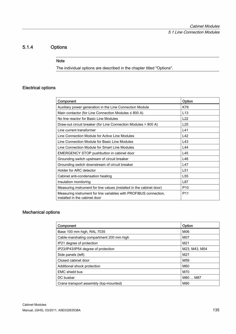
Cabinet Modules 5.1 Line Connection Modules
Cabinet Modules Manual, (GH5), 03/2011, A5E03263538A 135
5.1.4 Options
Note
The individual options are described in the chapter titled "Options".
Electrical options Component Option Auxiliary power generation in the Line Connection Module K76 Main contactor (for Line Connection Modules ≤ 800 A) L13 No line reactor for Basic Line Modules L22 Draw-out circuit breaker (for Line Connection Modules > 800 A) L25 Line current transformer L41 Line Connection Module for Active Line Modules L42 Line Connection Module for Basic Line Modules L43 Line Connection Module for Smart Line Modules L44 EMERGENCY STOP pushbutton in cabinet door L45 Grounding switch upstream of circuit breaker L46 Grounding switch downstream of circuit breaker L47 Holder for ARC detector L51 Cabinet anti-condensation heating L55 Insulation monitoring L87 Measuring instrument for line values (installed in the cabinet door) P10 Measuring instrument for line variables with PROFIBUS connection, installed in the cabinet door
P11
Mechanical options Component Option Base 100 mm high, RAL 7035 M06 Cable-marshaling compartment 200 mm high M07 IP21 degree of protection M21 IP23/IP43/IP54 degree of protection M23, M43, M54 Side panels (left) M27 Closed cabinet door M59 Additional shock protection M60 EMC shield bus M70 DC busbar M80 ... M87 Crane transport assembly (top-mounted) M90
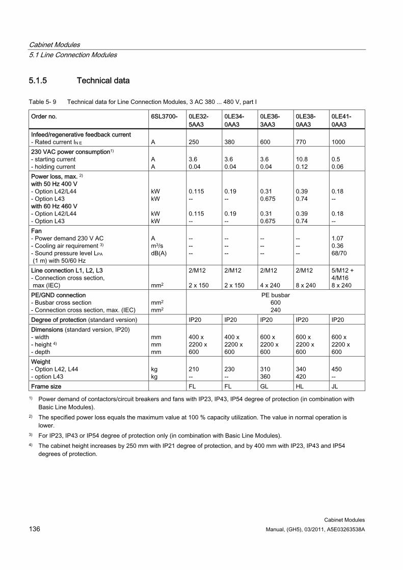
Cabinet Modules 5.1 Line Connection Modules
Cabinet Modules 136 Manual, (GH5), 03/2011, A5E03263538A
5.1.5 Technical data
Table 5- 9 Technical data for Line Connection Modules, 3 AC 380 ... 480 V, part I
Order no. 6SL3700- 0LE32- 5AA3
0LE34- 0AA3
0LE36- 3AA3
0LE38- 0AA3
0LE41- 0AA3
Infeed/regenerative feedback current - Rated current IN E
A
250
380
600
770
1000
230 VAC power consumption1) - starting current - holding current
A A
3.6 0.04
3.6 0.04
3.6 0.04
10.8 0.12
0.5 0.06
Power loss, max. 2) with 50 Hz 400 V - Option L42/L44 - Option L43 with 60 Hz 460 V - Option L42/L44 - Option L43
kW kW kW kW
0.115 -- 0.115 --
0.19 -- 0.19 --
0.31 0.675 0.31 0.675
0.39 0.74 0.39 0.74
0.18 -- 0.18 --
Fan - Power demand 230 V AC - Cooling air requirement 3) - Sound pressure level LPA (1 m) with 50/60 Hz
A m3/s dB(A)
-- -- --
-- -- --
-- -- --
-- -- --
1.07 0.36 68/70
Line connection L1, L2, L3 - Connection cross section, max (IEC)
mm2
2/M12 2 x 150
2/M12 2 x 150
2/M12 4 x 240
2/M12 8 x 240
5/M12 + 4/M16 8 x 240
PE/GND connection - Busbar cross section - Connection cross section, max. (IEC)
mm2
mm2
PE busbar 600 240
Degree of protection (standard version) IP20 IP20 IP20 IP20 IP20 Dimensions (standard version, IP20) - width - height 4) - depth
mm mm mm
400 x 2200 x 600
400 x 2200 x 600
600 x 2200 x 600
600 x 2200 x 600
600 x 2200 x 600
Weight - Option L42, L44 - option L43
kg kg
210 --
230 --
310 360
340 420
450 --
Frame size FL FL GL HL JL
1) Power demand of contactors/circuit breakers and fans with IP23, IP43, IP54 degree of protection (in combination with Basic Line Modules).
2) The specified power loss equals the maximum value at 100 % capacity utilization. The value in normal operation is lower.
3) For IP23, IP43 or IP54 degree of protection only (in combination with Basic Line Modules). 4) The cabinet height increases by 250 mm with IP21 degree of protection, and by 400 mm with IP23, IP43 and IP54
degrees of protection.
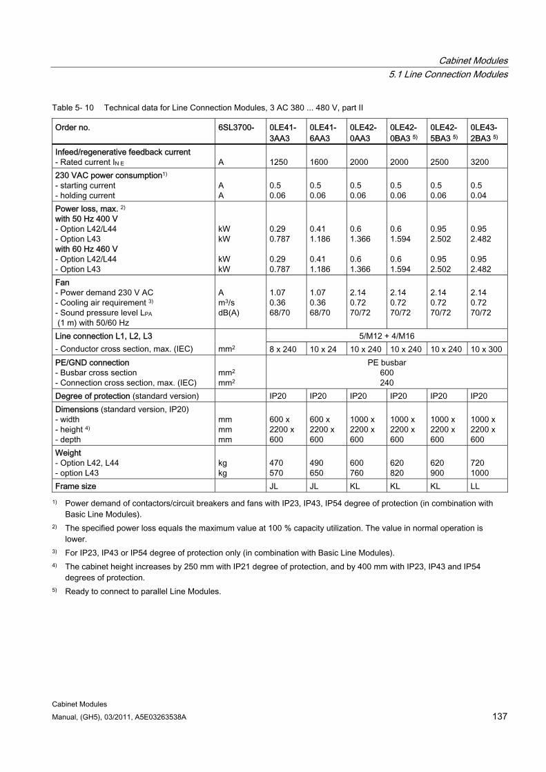
Cabinet Modules 5.1 Line Connection Modules
Cabinet Modules Manual, (GH5), 03/2011, A5E03263538A 137
Table 5- 10 Technical data for Line Connection Modules, 3 AC 380 ... 480 V, part II
Order no. 6SL3700- 0LE41- 3AA3
0LE41- 6AA3
0LE42- 0AA3
0LE42- 0BA3 5)
0LE42- 5BA3 5)
0LE43- 2BA3 5)
Infeed/regenerative feedback current - Rated current IN E
A
1250
1600
2000
2000
2500
3200
230 VAC power consumption1) - starting current - holding current
A A
0.5 0.06
0.5 0.06
0.5 0.06
0.5 0.06
0.5 0.06
0.5 0.04
Power loss, max. 2) with 50 Hz 400 V - Option L42/L44 - Option L43 with 60 Hz 460 V - Option L42/L44 - Option L43
kW kW kW kW
0.29 0.787 0.29 0.787
0.41 1.186 0.41 1.186
0.6 1.366 0.6 1.366
0.6 1.594 0.6 1.594
0.95 2.502 0.95 2.502
0.95 2.482 0.95 2.482
Fan - Power demand 230 V AC - Cooling air requirement 3)
- Sound pressure level LPA (1 m) with 50/60 Hz
A m3/s dB(A)
1.07 0.36 68/70
1.07 0.36 68/70
2.14 0.72 70/72
2.14 0.72 70/72
2.14 0.72 70/72
2.14 0.72 70/72
5/M12 + 4/M16 Line connection L1, L2, L3 - Conductor cross section, max. (IEC)
mm2 8 x 240 10 x 24 10 x 240 10 x 240 10 x 240 10 x 300
PE/GND connection - Busbar cross section - Connection cross section, max. (IEC)
mm2
mm2
PE busbar 600 240
Degree of protection (standard version) IP20 IP20 IP20 IP20 IP20 IP20 Dimensions (standard version, IP20) - width - height 4) - depth
mm mm mm
600 x 2200 x 600
600 x 2200 x 600
1000 x 2200 x 600
1000 x 2200 x 600
1000 x 2200 x 600
1000 x 2200 x 600
Weight - Option L42, L44 - option L43
kg kg
470 570
490 650
600 760
620 820
620 900
720 1000
Frame size JL JL KL KL KL LL
1) Power demand of contactors/circuit breakers and fans with IP23, IP43, IP54 degree of protection (in combination with Basic Line Modules).
2) The specified power loss equals the maximum value at 100 % capacity utilization. The value in normal operation is lower.
3) For IP23, IP43 or IP54 degree of protection only (in combination with Basic Line Modules). 4) The cabinet height increases by 250 mm with IP21 degree of protection, and by 400 mm with IP23, IP43 and IP54
degrees of protection. 5) Ready to connect to parallel Line Modules.
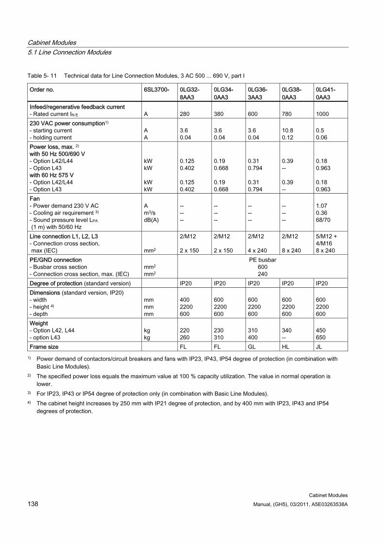
Cabinet Modules 5.1 Line Connection Modules
Cabinet Modules 138 Manual, (GH5), 03/2011, A5E03263538A
Table 5- 11 Technical data for Line Connection Modules, 3 AC 500 ... 690 V, part I
Order no. 6SL3700- 0LG32- 8AA3
0LG34- 0AA3
0LG36- 3AA3
0LG38- 0AA3
0LG41- 0AA3
Infeed/regenerative feedback current - Rated current IN E
A
280
380
600
780
1000
230 VAC power consumption1) - starting current - holding current
A A
3.6 0.04
3.6 0.04
3.6 0.04
10.8 0.12
0.5 0.06
Power loss, max. 2) with 50 Hz 500/690 V - Option L42/L44 - Option L43 with 60 Hz 575 V - Option L42/L44 - Option L43
kW kW kW kW
0.125 0.402 0.125 0.402
0.19 0.668 0.19 0.668
0.31 0.794 0.31 0.794
0.39 -- 0.39 --
0.18 0.963 0.18 0.963
Fan - Power demand 230 V AC - Cooling air requirement 3) - Sound pressure level LPA (1 m) with 50/60 Hz
A m3/s dB(A)
-- -- --
-- -- --
-- -- --
-- -- --
1.07 0.36 68/70
Line connection L1, L2, L3 - Connection cross section, max (IEC)
mm2
2/M12 2 x 150
2/M12 2 x 150
2/M12 4 x 240
2/M12 8 x 240
5/M12 + 4/M16 8 x 240
PE/GND connection - Busbar cross section - Connection cross section, max. (IEC)
mm2
mm2
PE busbar 600 240
Degree of protection (standard version) IP20 IP20 IP20 IP20 IP20 Dimensions (standard version, IP20) - width - height 4) - depth
mm mm mm
400 2200 600
600 2200 600
600 2200 600
600 2200 600
600 2200 600
Weight - Option L42, L44 - option L43
kg kg
220 260
230 310
310 400
340 --
450 650
Frame size FL FL GL HL JL
1) Power demand of contactors/circuit breakers and fans with IP23, IP43, IP54 degree of protection (in combination with Basic Line Modules).
2) The specified power loss equals the maximum value at 100 % capacity utilization. The value in normal operation is lower.
3) For IP23, IP43 or IP54 degree of protection only (in combination with Basic Line Modules). 4) The cabinet height increases by 250 mm with IP21 degree of protection, and by 400 mm with IP23, IP43 and IP54
degrees of protection.
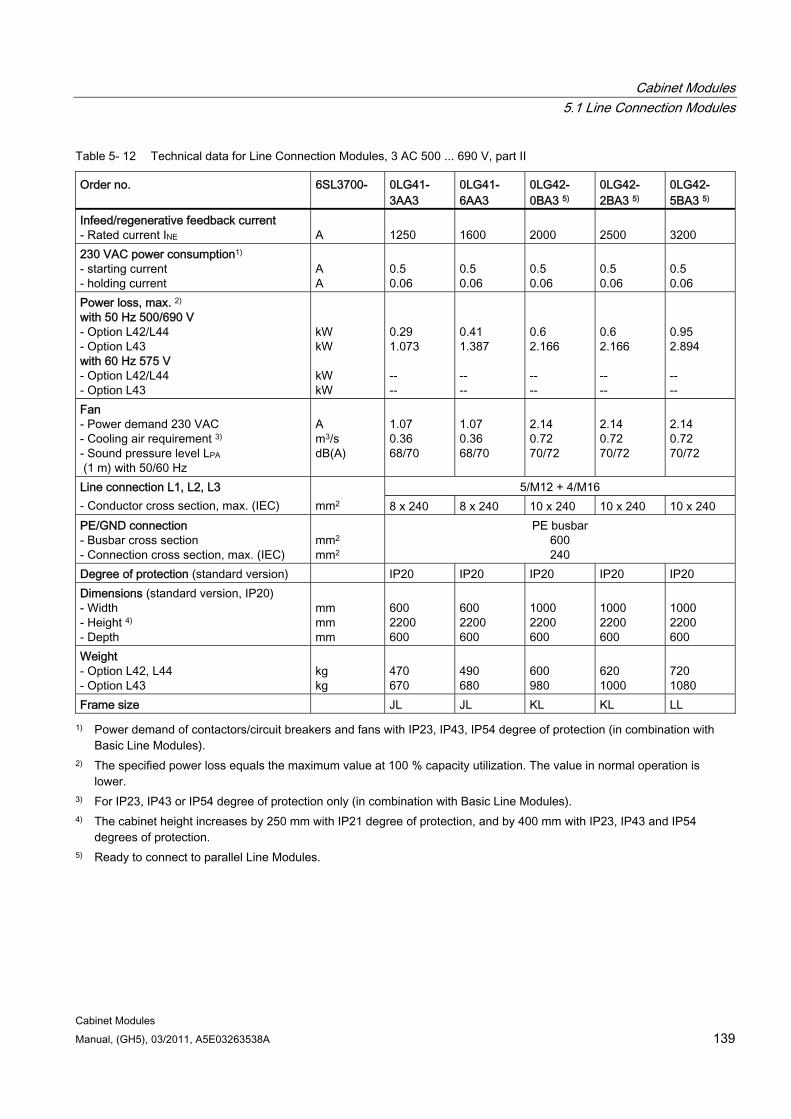
Cabinet Modules 5.1 Line Connection Modules
Cabinet Modules Manual, (GH5), 03/2011, A5E03263538A 139
Table 5- 12 Technical data for Line Connection Modules, 3 AC 500 ... 690 V, part II
Order no. 6SL3700- 0LG41- 3AA3
0LG41- 6AA3
0LG42- 0BA3 5)
0LG42- 2BA3 5)
0LG42- 5BA3 5)
Infeed/regenerative feedback current - Rated current INE
A
1250
1600
2000
2500
3200
230 VAC power consumption1) - starting current - holding current
A A
0.5 0.06
0.5 0.06
0.5 0.06
0.5 0.06
0.5 0.06
Power loss, max. 2) with 50 Hz 500/690 V - Option L42/L44 - Option L43 with 60 Hz 575 V - Option L42/L44 - Option L43
kW kW kW kW
0.29 1.073 -- --
0.41 1.387 -- --
0.6 2.166 -- --
0.6 2.166 -- --
0.95 2.894 -- --
Fan - Power demand 230 VAC - Cooling air requirement 3) - Sound pressure level LPA (1 m) with 50/60 Hz
A m3/s dB(A)
1.07 0.36 68/70
1.07 0.36 68/70
2.14 0.72 70/72
2.14 0.72 70/72
2.14 0.72 70/72
5/M12 + 4/M16 Line connection L1, L2, L3 - Conductor cross section, max. (IEC)
mm2 8 x 240 8 x 240 10 x 240 10 x 240 10 x 240
PE/GND connection - Busbar cross section - Connection cross section, max. (IEC)
mm2
mm2
PE busbar 600 240
Degree of protection (standard version) IP20 IP20 IP20 IP20 IP20 Dimensions (standard version, IP20) - Width - Height 4) - Depth
mm mm mm
600 2200 600
600 2200 600
1000 2200 600
1000 2200 600
1000 2200 600
Weight - Option L42, L44 - Option L43
kg kg
470 670
490 680
600 980
620 1000
720 1080
Frame size JL JL KL KL LL
1) Power demand of contactors/circuit breakers and fans with IP23, IP43, IP54 degree of protection (in combination with Basic Line Modules).
2) The specified power loss equals the maximum value at 100 % capacity utilization. The value in normal operation is lower.
3) For IP23, IP43 or IP54 degree of protection only (in combination with Basic Line Modules). 4) The cabinet height increases by 250 mm with IP21 degree of protection, and by 400 mm with IP23, IP43 and IP54
degrees of protection. 5) Ready to connect to parallel Line Modules.
Cabinet Modules 5.2 Basic Line Modules
Cabinet Modules 140 Manual, (GH5), 03/2011, A5E03263538A
5.2 Basic Line Modules
5.2.1 General information
DANGER
Hazardous voltages are present in certain parts of this equipment during operation of the cabinet unit. Only qualified personnel may work on the cabinet. Such personnel must be thoroughly familiar with all the warnings and maintenance procedures for the cabinet described in the documentation provided.
The successful and safe operation of this cabinet is dependent on correct transport, proper storage and installation, as well as careful operation and maintenance. National safety regulations must be observed.
5.2.2 Description
Note
Refer to the layout diagrams (AO) and circuit diagrams (SP) provided on the customer DVD supplied with the device for the arrangement of components and interfaces, and for wiring.
Basic Line Modules are compact supply infeeds for 2-quadrant operation (i.e. no regenerative feedback).
Under full load, the DC-link voltage is higher than the rms value of the rated line voltage by a factor of 1.32, and under partial load by a factor of 1.35.
They are used in applications where energy does not have to be fed back into the line.
If regenerative conditions occur in the drive line-up, Braking Modules must be used because they convert the excess energy in braking resistors into heat.
Basic Line Modules are suitable for connection to supply systems grounded at the neutral point (TN, TT) and non-grounded (IT) supply systems. The following voltages and power ratings are available:
Line voltage Rated power 380 to 480 V AC, 3-phase 200 ... 900 kW 500 to 690 V AC, 3-phase 250 ... 1500 kW
The power rating can be increased by connecting Basic Line Modules in parallel.
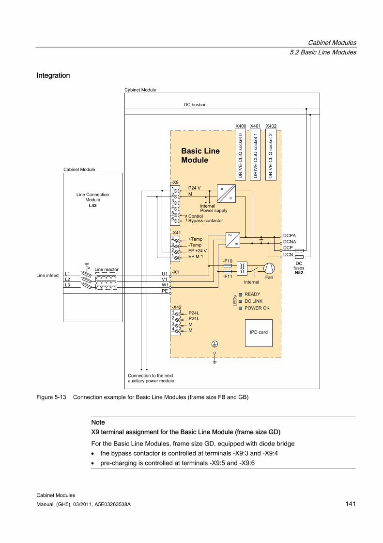
Cabinet Modules 5.2 Basic Line Modules
Cabinet Modules Manual, (GH5), 03/2011, A5E03263538A 141
Integration
L43
N52
Basic Line Module
Figure 5-13 Connection example for Basic Line Modules (frame size FB and GB)
Note X9 terminal assignment for the Basic Line Module (frame size GD)
For the Basic Line Modules, frame size GD, equipped with diode bridge the bypass contactor is controlled at terminals -X9:3 and -X9:4 pre-charging is controlled at terminals -X9:5 and -X9:6
Cabinet Modules 5.2 Basic Line Modules
Cabinet Modules 142 Manual, (GH5), 03/2011, A5E03263538A
Configuration In Basic Line Modules of frame sizes FB and GB, a fully-controlled thyristor bridge is used to pre-charge the Basic Line Module and the connected DC link. The thyristors normally operate with a trigger delay angle of 0 °.
Basic Line Modules of type GD for 900 kW (400 V) or 1500 kW (690 V) feature a diode bridge. On these units, the DC link is precharged via a separate, line-side precharging device.
Note
The configuration examples of the individual Basic Line Modules are used to illustrate the positioning of the factory-fitted components. They show the maximum possible configuration of the modules, which contain all options that can be ordered.
Refer to the layout diagrams (AO) on the customer DVD for the precise order-specific location of the components.
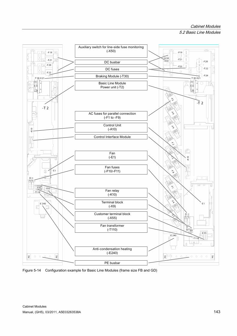
Cabinet Modules 5.2 Basic Line Modules
Cabinet Modules Manual, (GH5), 03/2011, A5E03263538A 143
C /L +
D/L -
-F 19
-F 21
-F 20
-F 22
AC
BL
MF
-F10
-F11
-T110
-T 2
-E 1
-K10-X 9
-E 240
-T 30.X 21
130-X55
-A1
0P
E
PE
C /L +
D/L -
-T 2
-E 1
-X9
-T 110
-F10
-F11
-K1
0
-F1-F 4
-F 7-F
8-F
5-F
2-F3
-F 6-F 9
-E 240
F _Schienen_G600
-F 20
-F 22
-F 24
-F19
-F21
-F23
130-X 55
-A10
-Q 50-X50
PE
PE
-T 30.X21
Figure 5-14 Configuration example for Basic Line Modules (frame size FB and GD)
Cabinet Modules 5.2 Basic Line Modules
Cabinet Modules 144 Manual, (GH5), 03/2011, A5E03263538A
Parallel connection of Basic Line Modules to increase power rating A pair of Basic Line Modules is available for creating drive line-ups with more power. These modules can be operated on a common Line Connection Module and are arranged to the right and left of the Line Connection Module. The power connections on the Basic Line Module on the left of the Line Connection Module are a mirror image (order number with C in the next-to-last position, example: 6SL3730-1Tx41-xBC3), which produces a very compact design for the line supply infeed.
The following rules must be observed when connecting Basic Line Modules in parallel:
Up to 4 identical Basic Line Modules can be connected in parallel.
A common Control Unit is required whenever the modules are connected in parallel.
Special Line Connection Modules are available for connecting the modules in parallel.
With multiple infeeds, power must be supplied to the systems from a common infeed point (i.e. the modules cannot be operated on different supplies).
A derating factor of 7.5% must be taken into consideration, regardless of the number of modules connected in parallel.

Cabinet Modules 5.2 Basic Line Modules
Cabinet Modules Manual, (GH5), 03/2011, A5E03263538A 145
5.2.3 Interface description
5.2.3.1 General information This chapter describes only those interfaces in the cabinet unit that require additional connection work by the customer. All other interfaces are pre-wired at the factory and are not designed for customer connections.
Note
All connections to be established on the plant side as well as the interfaces for integration into the plant control system are described in the circuit diagrams and terminal diagrams on the customer DVD supplied with the device.
5.2.3.2 Control Interface Module
Figure 5-15 Control Interface Module
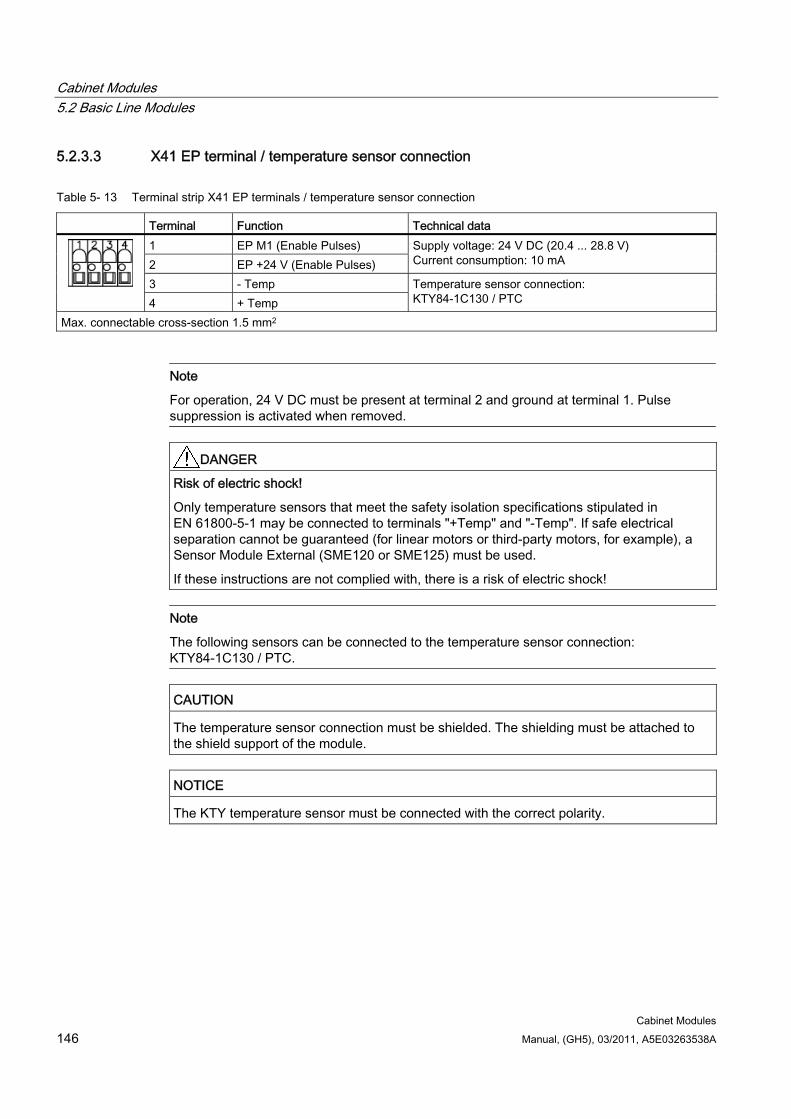
Cabinet Modules 5.2 Basic Line Modules
Cabinet Modules 146 Manual, (GH5), 03/2011, A5E03263538A
5.2.3.3 X41 EP terminal / temperature sensor connection
Table 5- 13 Terminal strip X41 EP terminals / temperature sensor connection
Terminal Function Technical data 1 EP M1 (Enable Pulses) 2 EP +24 V (Enable Pulses)
Supply voltage: 24 V DC (20.4 ... 28.8 V) Current consumption: 10 mA
3 - Temp 4 + Temp
Temperature sensor connection: KTY84-1C130 / PTC
Max. connectable cross-section 1.5 mm2
Note
For operation, 24 V DC must be present at terminal 2 and ground at terminal 1. Pulse suppression is activated when removed.
DANGER Risk of electric shock!
Only temperature sensors that meet the safety isolation specifications stipulated in EN 61800-5-1 may be connected to terminals "+Temp" and "-Temp". If safe electrical separation cannot be guaranteed (for linear motors or third-party motors, for example), a Sensor Module External (SME120 or SME125) must be used.
If these instructions are not complied with, there is a risk of electric shock!
Note
The following sensors can be connected to the temperature sensor connection: KTY84-1C130 / PTC.
CAUTION The temperature sensor connection must be shielded. The shielding must be attached to the shield support of the module.
NOTICE The KTY temperature sensor must be connected with the correct polarity.

Cabinet Modules 5.2 Basic Line Modules
Cabinet Modules Manual, (GH5), 03/2011, A5E03263538A 147
5.2.3.4 DRIVE-CLiQ interfaces X400, X401, X402
Table 5- 14 DRIVE-CLiQ interfaces X400, X401, X402
PIN Signal name Technical specifications 1 TXP Transmit data + 2 TXN Transmit data - 3 RXP Receive data + 4 Reserved, do not use 5 Reserved, do not use 6 RXN Receive data - 7 Reserved, do not use 8 Reserved, do not use A + (24 V) 24 V power supply
B M (0 V) Electronics ground Blanking plate for DRIVE-CLiQ interfaces (50 pcs.) order number: 6SL3066-4CA00-0AA0
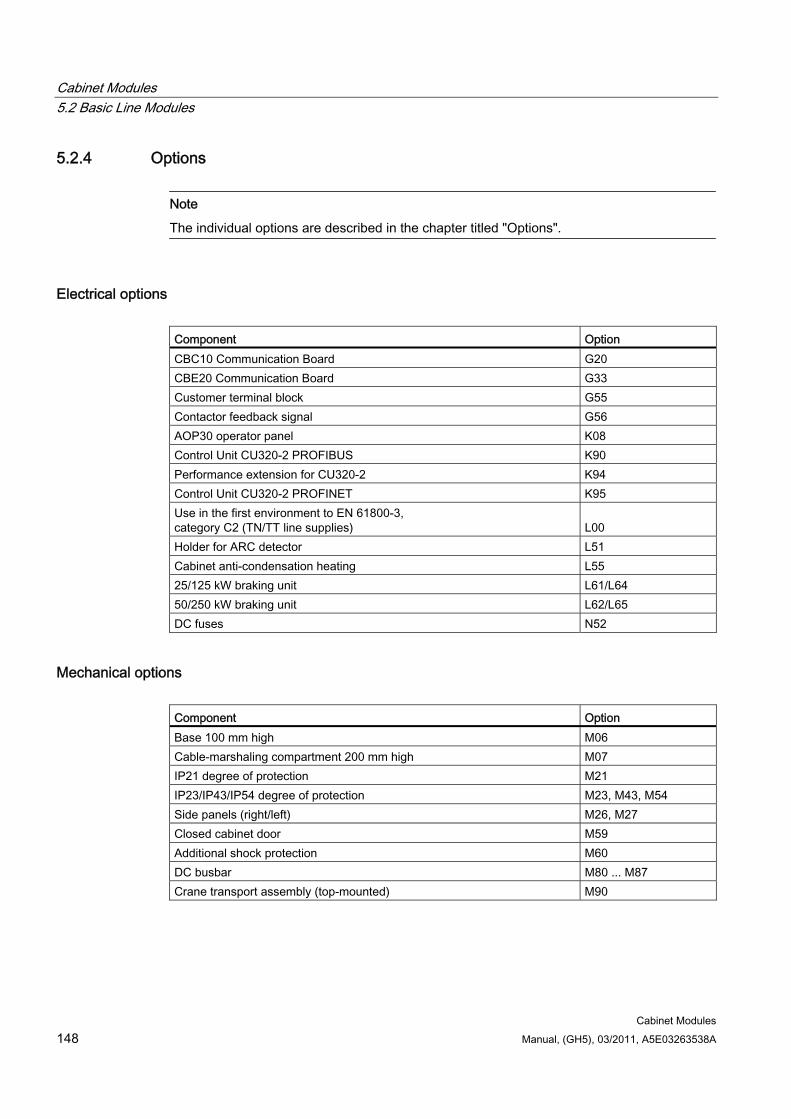
Cabinet Modules 5.2 Basic Line Modules
Cabinet Modules 148 Manual, (GH5), 03/2011, A5E03263538A
5.2.4 Options
Note
The individual options are described in the chapter titled "Options".
Electrical options Component Option CBC10 Communication Board G20 CBE20 Communication Board G33 Customer terminal block G55 Contactor feedback signal G56 AOP30 operator panel K08 Control Unit CU320-2 PROFIBUS K90 Performance extension for CU320-2 K94 Control Unit CU320-2 PROFINET K95 Use in the first environment to EN 61800-3, category C2 (TN/TT line supplies)
L00
Holder for ARC detector L51 Cabinet anti-condensation heating L55 25/125 kW braking unit L61/L64 50/250 kW braking unit L62/L65 DC fuses N52
Mechanical options Component Option Base 100 mm high M06 Cable-marshaling compartment 200 mm high M07 IP21 degree of protection M21 IP23/IP43/IP54 degree of protection M23, M43, M54 Side panels (right/left) M26, M27 Closed cabinet door M59 Additional shock protection M60 DC busbar M80 ... M87 Crane transport assembly (top-mounted) M90
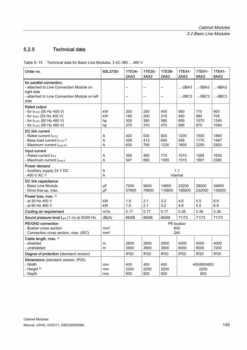
Cabinet Modules 5.2 Basic Line Modules
Cabinet Modules Manual, (GH5), 03/2011, A5E03263538A 149
5.2.5 Technical data
Table 5- 15 Technical data for Basic Line Modules, 3 AC 380 ... 480 V
Order no. 6SL3730- 1TE34- 2AA3
1TE35- 3AA3
1TE38- 2AA3
1TE41- 2AA3
1TE41-5AA3
1TE41- 8AA3
for parallel connection, - attached to Line Connection Module on right side - attached to Line Connection Module on left side
-- --
-- --
-- --
...-2BA3 ...-2BC3
...-5BA3 ...-5BC3
...-8BA3 ...-8BC3
Rated output - for IN DC (50 Hz 400 V) - for IHDC (50 Hz 400 V) - for IN DC (60 Hz 460 V) - for IH DC (60 Hz 460 V)
kW kW hp hp
200 160 305 275
250 200 380 310
400 315 585 475
560 450 855 695
710 560 1070 870
900 705 1340 1090
DC link current - Rated current IN DC - Base load current IH DC1) - Maximum current Imax DC
A A A
420 328 630
530 413 795
820 640 1230
1200 936 1800
1500 1170 2250
1880 1467 2820
Input current - Rated current IN E - Maximum current Imax E
A A
365 547
460 690
710 1065
1010 1515
1265 1897
1630 2380
Power demand - Auxiliary supply 24 V DC - 400 V AC 2)
A A
1.1
internal DC link capacitance - Basic Line Module - Drive line-up, max.
µF µF
7200 57600
9600 76800
14600 116800
23200 185600
29000 232000
34800 139200
Power loss, max. 3) - at 50 Hz 400 V - at 60 Hz 460 V
kW kW
1.9 1.9
2.1 2.1
3.2 3.2
4.6 4.6
5.5 5.5
6.9 6.9
Cooling air requirement m3/s 0.17 0.17 0.17 0.36 0.36 0.36 Sound pressure level LpA (1 m) at 50/60 Hz dB(A) 66/68 66/68 66/68 71/73 71/73 71/73 PE/GND connection - Busbar cross section - Connection cross section, max. (IEC)
mm2
mm2
PE busbar 600 240
Cable length, max. 4) - shielded - unshielded
m m
2600 3900
2600 3900
2600 3900
4000 6000
4000 6000
4000 7200
Degree of protection (standard version) IP20 IP20 IP20 IP20 IP20 IP20 Dimensions (standard version, IP20) - Width - Height 5) - Depth
mm mm mm
400 2200 600
400 2200 600
400 2200 600
400/600/600
2200 600

Cabinet Modules 5.2 Basic Line Modules
Cabinet Modules 150 Manual, (GH5), 03/2011, A5E03263538A
Order no. 6SL3730- 1TE34- 2AA3
1TE35- 3AA3
1TE38- 2AA3
1TE41- 2AA3
1TE41- 5AA3
1TE41- 8AA3
Weight (standard version) kg 166 166 166 320/440/480 Frame size FB FB FB GB GB GD
1) The base load current IH DCis based on a duty cycle of 150 % for 60 s or Imax DCfor 5 s with a duty cycle duration of 300 s. 2) The power required for the 400 V AC auxiliary supply is provided by the supply input voltage. 3) The specified power loss equals the maximum value at 100 % capacity utilization. The value in normal operation is
lower. 4) Total of all motor cables and DC link. Longer cable lengths for specific configurations are available on request. 5) The cabinet height increases by 250 mm with IP21 degree of protection, and by 400 mm with IP23, IP43 and IP54
degrees of protection.
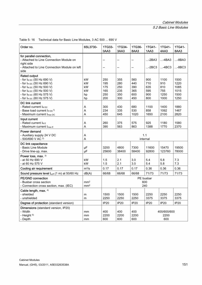
Cabinet Modules 5.2 Basic Line Modules
Cabinet Modules Manual, (GH5), 03/2011, A5E03263538A 151
Table 5- 16 Technical data for Basic Line Modules, 3 AC 500 ... 690 V
Order no. 6SL3730- 1TG33-0AA3
1TG34-3AA3
1TG36-8AA3
1TG41- 1AA3
1TG41-4AA3
1TG41-8AA3
for parallel connection, - Attached to Line Connection Module on right side - Attached to Line Connection Module on left side
-- --
-- --
-- --
...-2BA3 ...-2BC3
...-4BA3 ...-4BC3
...-8BA3 ...-8BC3
Rated output - for IN DC (50 Hz 690 V) - for IH DC (50 Hz 690 V) - for IN DC (50 Hz 500 V) - for IN DC (50 Hz 500 V) - for IN DC (60 Hz 575 V) - for IH DC (60 Hz 575 V)
kW kW kW kW hp hp
250 195 175 165 250 200
355 280 250 235 350 300
560 440 390 365 600 450
900 710 635 595 900 800
1100 910 810 755 1250 1000
1500 1220 1085 1015 1500 1250
DC link current - Rated current IN DC - Base load current IH DC1) - Maximum current Imax DC
A A A
300 234 450
430 335 645
680 530 1020
1100 858 1650
1400 1092 2100
1880 1467 2820
Input current - Rated current IN E - Maximum current Imax E
A A
260 390
375 563
575 863
925 1388
1180 1770
1580 2370
Power demand - Auxiliary supply 24 V DC - 500/690 V AC 2)
A A
1.1
internal DC link capacitance - Basic Line Module - Drive line-up, max.
µF µF
3200 25600
4800 38400
7300 58400
11600 92800
15470 123760
19500 78000
Power loss, max. 3) - at 50 Hz 690 V - at 60 Hz 575 V
kW kW
1.5 1.5
2.1 2.1
3.0 3.0
5.4 5.4
5.8 5.8
7.3 7.3
Cooling air requirement m3/s 0.17 0.17 0.17 0.36 0.36 0.36 Sound pressure level LpA (1 m) at 50/60 Hz dB(A) 66/68 66/68 66/68 71/73 71/73 71/73 PE/GND connection - Busbar cross section - Connection cross section, max. (IEC)
mm2
mm2
PE busbar 600 240
Cable length, max. 4) - shielded - unshielded
m m
1500 2250
1500 2250
1500 2250
2250 3375
2250 3375
2250 3375
Degree of protection (standard version) IP20 IP20 IP20 IP20 IP20 IP20 Dimensions (standard version, IP20) - Width - Height 5) - Depth
mm mm mm
400 2200 600
400 2200 600
400 2200 600
400/600/600
2200 600
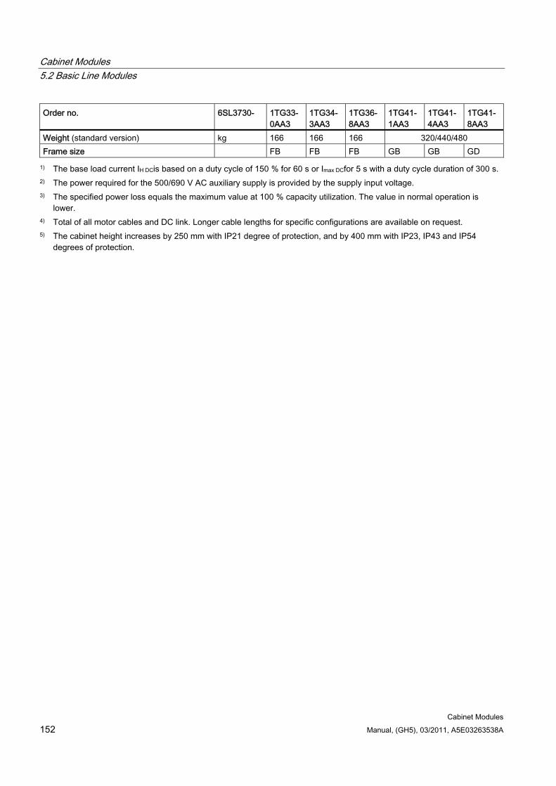
Cabinet Modules 5.2 Basic Line Modules
Cabinet Modules 152 Manual, (GH5), 03/2011, A5E03263538A
Order no. 6SL3730- 1TG33-0AA3
1TG34-3AA3
1TG36-8AA3
1TG41- 1AA3
1TG41- 4AA3
1TG41-8AA3
Weight (standard version) kg 166 166 166 320/440/480 Frame size FB FB FB GB GB GD
1) The base load current IH DCis based on a duty cycle of 150 % for 60 s or Imax DCfor 5 s with a duty cycle duration of 300 s. 2) The power required for the 500/690 V AC auxiliary supply is provided by the supply input voltage. 3) The specified power loss equals the maximum value at 100 % capacity utilization. The value in normal operation is
lower. 4) Total of all motor cables and DC link. Longer cable lengths for specific configurations are available on request. 5) The cabinet height increases by 250 mm with IP21 degree of protection, and by 400 mm with IP23, IP43 and IP54
degrees of protection.
Cabinet Modules 5.3 Smart Line Modules
Cabinet Modules Manual, (GH5), 03/2011, A5E03263538A 153
5.3 Smart Line Modules
5.3.1 General information
DANGER
Hazardous voltages are present in certain parts of this equipment during operation of the cabinet unit. Only qualified personnel may work on the cabinet. Such personnel must be thoroughly familiar with all the warnings and maintenance procedures for the cabinet described in the documentation provided.
The successful and safe operation of this cabinet is dependent on correct transport, proper storage and installation, as well as careful operation and maintenance. National safety regulations must be observed.
5.3.2 Description
Note
Refer to the layout diagrams (AO) and circuit diagrams (SP) provided on the customer DVD supplied with the device for the arrangement of components and interfaces, and for wiring.
Smart Line Modules are infeed/regenerative feedback units. Like the Basic Line Module, they supply energy to the connected Motor Modules, but unlike the Basic Line Module, they can feed back regenerative energy. The infeed occurs over a diode jumper, while stable, line-commutated regenerative feedback takes place via IGBTs with 100% continuous energy regeneration.
Under full load, the DC link voltage is higher than the rms value of the rated line voltage by a factor of 1.30, and under partial load by a factor of 1.32.
Smart Line Modules are suitable for connection to supply systems grounded at the neutral point (TN, TT) and non-grounded (IT) supply systems. The following voltages and power ratings are available:
Line voltage Rated power 380 to 480 V AC, 3-phase 250 ... 800 kW 500 to 690 V AC, 3-phase 450 ... 1400 kW
The power rating can be increased by connecting Smart Line Modules in parallel.
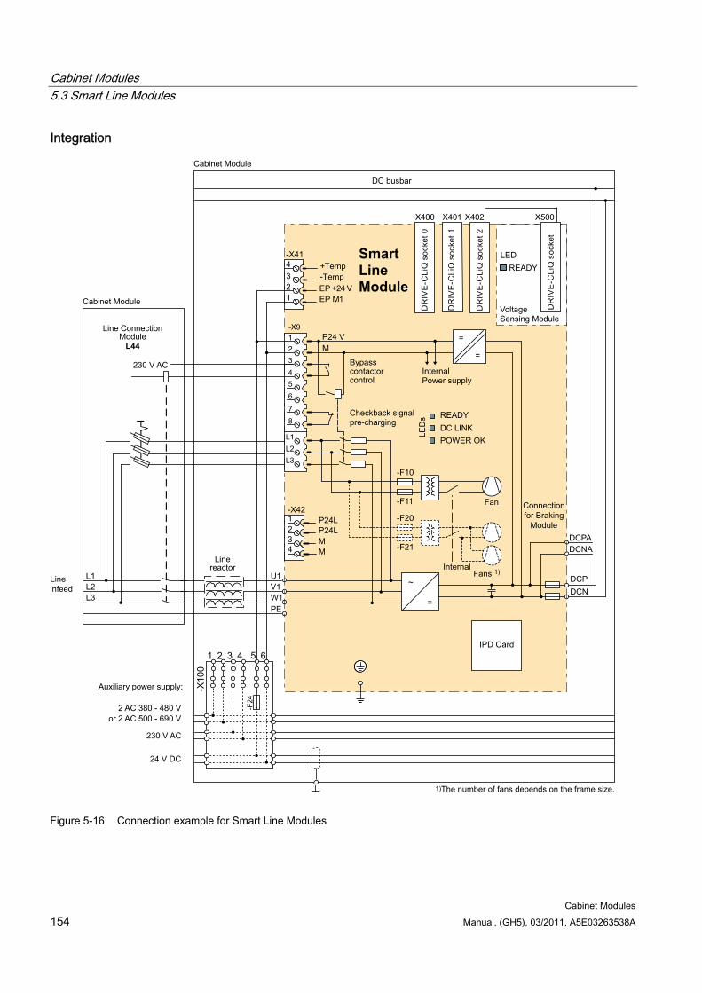
Cabinet Modules 5.3 Smart Line Modules
Cabinet Modules 154 Manual, (GH5), 03/2011, A5E03263538A
Integration
Bypasscontactor control
InternalPower supply
1)The number of fans depends on the frame size.
Internal
Fan
Fans 1)
24 V DC
230 V AC
2 AC 380 - 480 Vor 2 AC 500 - 690 V
Checkback signalpre-charging
Line infeed
DC busbar
Line reactor
Connection for Braking
Module
Auxiliary power supply:
230 V AC
2
VoltageSensing Module
LED READY
Cabinet Module
Cabinet Module
Line Connection Module
L44
Smart Line Module
=
~
-F21
-F20
-F11
-F10
=
=M P24 V
7 8
5 6
3 4
1 -X9
L1
L3L2
11234-X41
EP M+24 VEP
DCNADCPA
DCNDCP
PEW1V1U1
L3L2L1
X400
X401 X402 X500
Figure 5-16 Connection example for Smart Line Modules
Cabinet Modules 5.3 Smart Line Modules
Cabinet Modules Manual, (GH5), 03/2011, A5E03263538A 155
Configuration IGBTs (fundamental frequency-switched) are used as power semiconductors of the Smart Line Modules. Because this reduces switching losses, high current utilization of the power units can be achieved.
The current flows in the direction of the infeed via the freewheeling diodes of the IGBTs. While a diode is conducting, the anti-parallel IGBT is also activated. If the DC link voltage increases due to regenerative operation of the drives, the IGBTs conduct electricity, thus feeding the energy back into the supply system.
Smart Line Modules do not require a line-side filter. A line reactor (4% uk) is included in the standard package. The unit has a built-in pre-charging input circuit for the DC link capacitors. For this purpose, a main contactor or a motor-operated circuit breaker is included in the Line Connection Module on the line side.
It should be noted that the capacity of the pre-charging input circuit for charging the DC link capacitors depends on the unit being used. It is limited to no more than 4 to 7.8 times the value of the DC link capacitance installed in the device.
Note
The configuration examples of the individual Smart Line Modules are used to illustrate the positioning of the factory-fitted components. They show the maximum possible configuration of the modules, which contain all options that can be ordered.
Refer to the layout diagrams (AO) on the customer DVD for the precise order-specific location of the components.
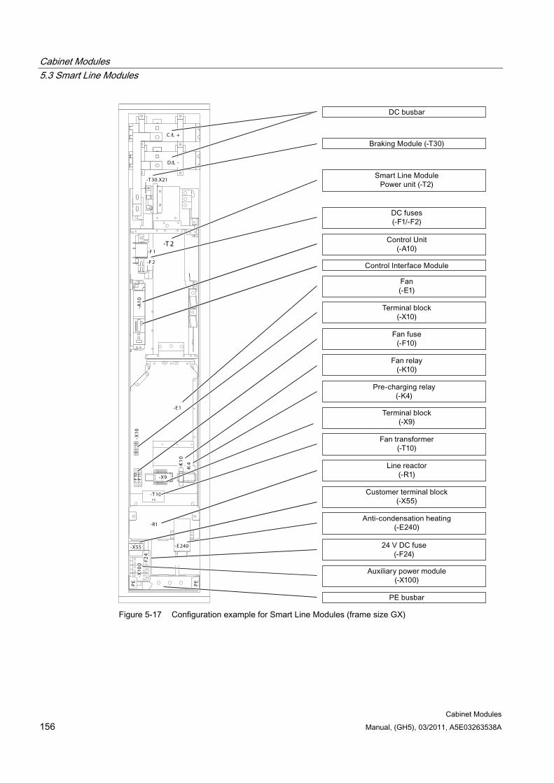
Cabinet Modules 5.3 Smart Line Modules
Cabinet Modules 156 Manual, (GH5), 03/2011, A5E03263538A
-R 1-X55
-X10
0 -F2
4
PE
PE
-T 2
-E 1
-F10
-F11
-K4
P E
-T 10
-X10
-K1
0
-X9
-F 1
-F 2
-A1
0
-T 30.X21
L1
D/L -
C /L +
-E 240
-R1
Figure 5-17 Configuration example for Smart Line Modules (frame size GX)
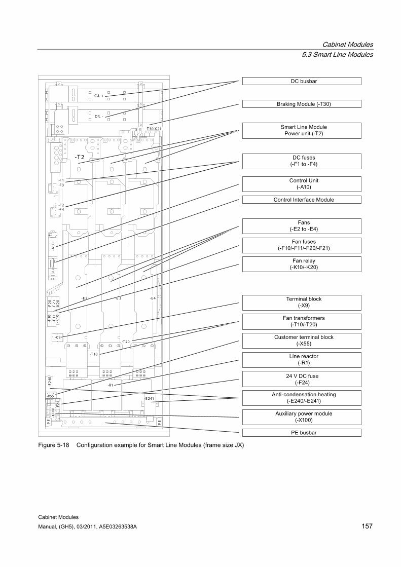
Cabinet Modules 5.3 Smart Line Modules
Cabinet Modules Manual, (GH5), 03/2011, A5E03263538A 157
-R1
-X1
00-F
24
PE
PE
-T 2
-F2
0-F
21
-F10
-F11
-K2
0-K
10
-E 2 -E 3 -E 4
-X 9
-T 10
-T 20
-F 1-F 3
-F 2-F 4
-A1
0-E
240
-E 241
-T 30.X 21
SLM
_H
C /L +
D/L -
-X55
Figure 5-18 Configuration example for Smart Line Modules (frame size JX)
Cabinet Modules 5.3 Smart Line Modules
Cabinet Modules 158 Manual, (GH5), 03/2011, A5E03263538A
Parallel connection of Smart Line Modules to increase power rating Up to four Smart Line Modules with the same power rating can be connected in parallel in order to increase power.
Smart Line Modules with "mirror-image" power connections enable the parallel connection of these modules in a compact configuration. Order numbers for devices that are arranged to the left of the Line Connection Module have a "C" in the next-to-last position, example: 6SL3730-6TE41-1BC3.
The following rules must be observed when connecting Smart Line Modules in parallel:
Up to 4 identical Smart Line Modules can be connected in parallel.
The parallel connection must be implemented using a Control Unit.
A 4% reactor is always required upstream of each Smart Line Module for the purpose of current balancing.
Special Line Connection Modules are available for connecting the modules in parallel.
With multiple infeeds, power must be supplied to the systems from a common infeed point (i.e. the modules cannot be operated on different supplies).
A derating factor of 7.5% must be taken into consideration, regardless of the number of modules connected in parallel.
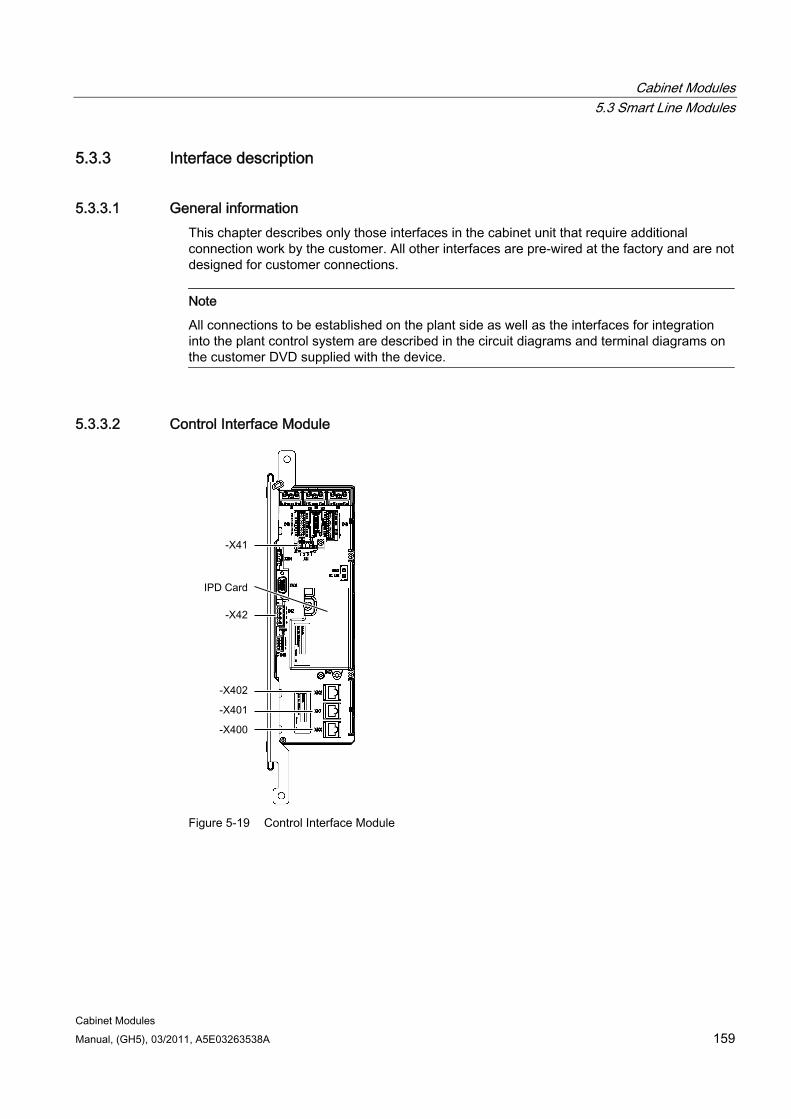
Cabinet Modules 5.3 Smart Line Modules
Cabinet Modules Manual, (GH5), 03/2011, A5E03263538A 159
5.3.3 Interface description
5.3.3.1 General information This chapter describes only those interfaces in the cabinet unit that require additional connection work by the customer. All other interfaces are pre-wired at the factory and are not designed for customer connections.
Note
All connections to be established on the plant side as well as the interfaces for integration into the plant control system are described in the circuit diagrams and terminal diagrams on the customer DVD supplied with the device.
5.3.3.2 Control Interface Module
Figure 5-19 Control Interface Module
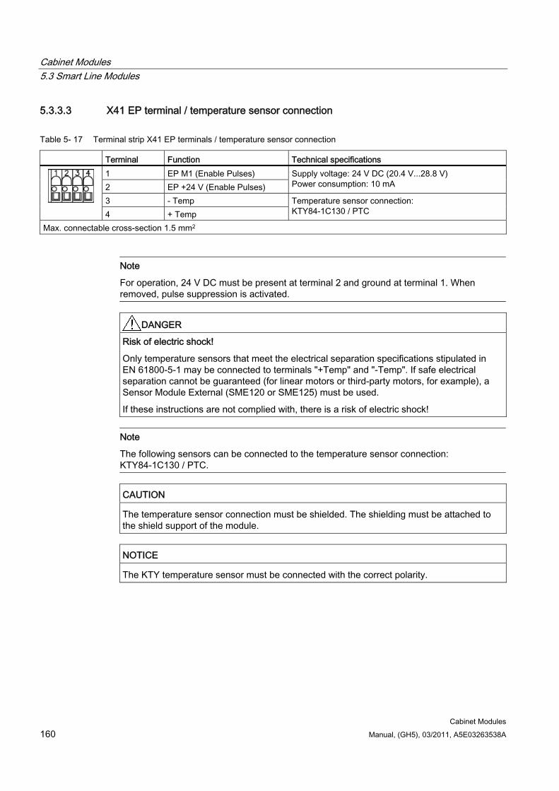
Cabinet Modules 5.3 Smart Line Modules
Cabinet Modules 160 Manual, (GH5), 03/2011, A5E03263538A
5.3.3.3 X41 EP terminal / temperature sensor connection
Table 5- 17 Terminal strip X41 EP terminals / temperature sensor connection
Terminal Function Technical specifications 1 EP M1 (Enable Pulses) 2 EP +24 V (Enable Pulses)
Supply voltage: 24 V DC (20.4 V...28.8 V) Power consumption: 10 mA
3 - Temp 4 + Temp
Temperature sensor connection: KTY84-1C130 / PTC
Max. connectable cross-section 1.5 mm2
Note
For operation, 24 V DC must be present at terminal 2 and ground at terminal 1. When removed, pulse suppression is activated.
DANGER Risk of electric shock!
Only temperature sensors that meet the electrical separation specifications stipulated in EN 61800-5-1 may be connected to terminals "+Temp" and "-Temp". If safe electrical separation cannot be guaranteed (for linear motors or third-party motors, for example), a Sensor Module External (SME120 or SME125) must be used.
If these instructions are not complied with, there is a risk of electric shock!
Note
The following sensors can be connected to the temperature sensor connection: KTY84-1C130 / PTC.
CAUTION The temperature sensor connection must be shielded. The shielding must be attached to the shield support of the module.
NOTICE The KTY temperature sensor must be connected with the correct polarity.
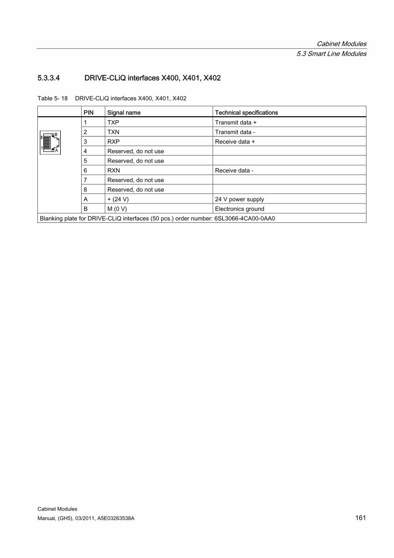
Cabinet Modules 5.3 Smart Line Modules
Cabinet Modules Manual, (GH5), 03/2011, A5E03263538A 161
5.3.3.4 DRIVE-CLiQ interfaces X400, X401, X402
Table 5- 18 DRIVE-CLiQ interfaces X400, X401, X402
PIN Signal name Technical specifications 1 TXP Transmit data + 2 TXN Transmit data - 3 RXP Receive data + 4 Reserved, do not use 5 Reserved, do not use 6 RXN Receive data - 7 Reserved, do not use 8 Reserved, do not use A + (24 V) 24 V power supply
B M (0 V) Electronics ground Blanking plate for DRIVE-CLiQ interfaces (50 pcs.) order number: 6SL3066-4CA00-0AA0
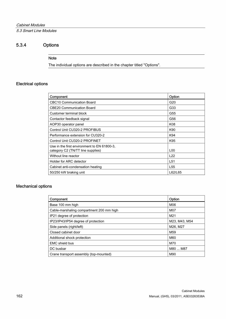
Cabinet Modules 5.3 Smart Line Modules
Cabinet Modules 162 Manual, (GH5), 03/2011, A5E03263538A
5.3.4 Options
Note
The individual options are described in the chapter titled "Options".
Electrical options Component Option CBC10 Communication Board G20 CBE20 Communication Board G33 Customer terminal block G55 Contactor feedback signal G56 AOP30 operator panel K08 Control Unit CU320-2 PROFIBUS K90 Performance extension for CU320-2 K94 Control Unit CU320-2 PROFINET K95 Use in the first environment to EN 61800-3, category C2 (TN/TT line supplies)
L00
Without line reactor L22 Holder for ARC detector L51 Cabinet anti-condensation heating L55 50/250 kW braking unit L62/L65
Mechanical options Component Option Base 100 mm high M06 Cable-marshaling compartment 200 mm high M07 IP21 degree of protection M21 IP23/IP43/IP54 degree of protection M23, M43, M54 Side panels (right/left) M26, M27 Closed cabinet door M59 Additional shock protection M60 EMC shield bus M70 DC busbar M80 ... M87 Crane transport assembly (top-mounted) M90
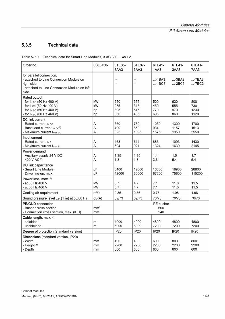
Cabinet Modules 5.3 Smart Line Modules
Cabinet Modules Manual, (GH5), 03/2011, A5E03263538A 163
5.3.5 Technical data
Table 5- 19 Technical data for Smart Line Modules, 3 AC 380 ... 480 V
Order no. 6SL3730- 6TE35- 5AA3
6TE37- 3AA3
6TE41- 1AA3
6TE41- 3AA3
6TE41- 7AA3
for parallel connection, - attached to Line Connection Module on right side - attached to Line Connection Module on left side
-- --
-- --
...-1BA3 ...-1BC3
...-3BA3 ...-3BC3
...-7BA3 ...-7BC3
Rated output - for IN DC (50 Hz 400 V) - for IHDC (50 Hz 400 V) - for IN DC (60 Hz 460 V) - for IH DC (60 Hz 460 V)
kW kW hp hp
250 235 395 360
355 315 545 485
500 450 770 695
630 555 970 860
800 730 1230 1120
DC link current - Rated current IN DC - Base load current IH DC1) - Maximum current Imax DC
A A A
550 490 825
730 650 1095
1050 934 1575
1300 1157 1950
1700 1513 2550
Input current - Rated current IN E - Maximum current Imax E
A A
463 694
614 921
883 1324
1093 1639
1430 2145
Power demand - Auxiliary supply 24 V DC - 400 V AC 2)
A A
1.35 1.8
1.35 1.8
1.4 3.6
1.5 5.4
1.7 5.4
DC link capacitance - Smart Line Module - Drive line-up, max.
µF µF
8400 42000
12000 60000
16800 67200
18900 75600
28800 115200
Power loss, max. 3) - at 50 Hz 400 V - at 60 Hz 460 V
kW kW
3.7 3.7
4.7 4.7
7.1 7.1
11.0 11.0
11.5 11.5
Cooling air requirement m3/s 0.36 0.36 0.78 1.08 1.08 Sound pressure level LpA (1 m) at 50/60 Hz dB(A) 69/73 69/73 70/73 70/73 70/73 PE/GND connection - Busbar cross section - Connection cross section, max. (IEC)
mm2
mm2
PE busbar 600 240
Cable length, max. 4) - shielded - unshielded
m m
4000 6000
4000 6000
4800 7200
4800 7200
4800 7200
Degree of protection (standard version) IP20 IP20 IP20 IP20 IP20 Dimensions (standard version, IP20) - Width - Height 5) - Depth
mm mm mm
400 2200 600
400 2200 600
600 2200 600
800 2200 600
800 2200 600
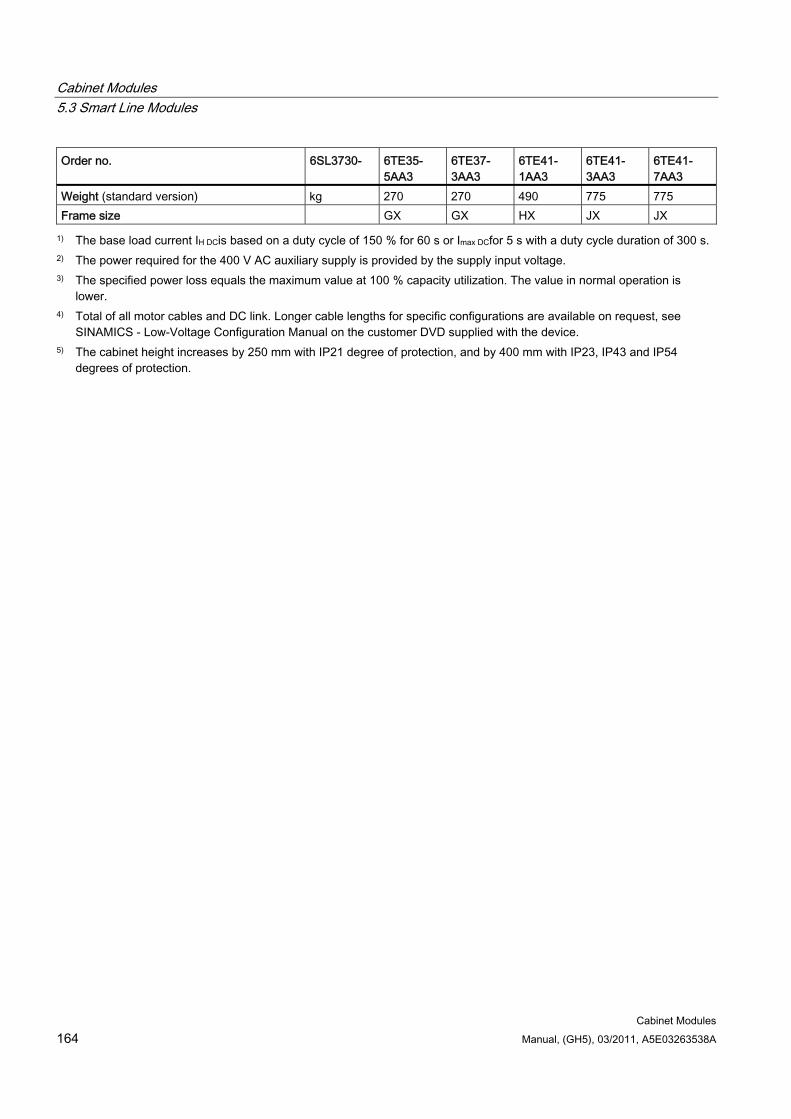
Cabinet Modules 5.3 Smart Line Modules
Cabinet Modules 164 Manual, (GH5), 03/2011, A5E03263538A
Order no. 6SL3730- 6TE35- 5AA3
6TE37- 3AA3
6TE41- 1AA3
6TE41- 3AA3
6TE41- 7AA3
Weight (standard version) kg 270 270 490 775 775 Frame size GX GX HX JX JX
1) The base load current IH DCis based on a duty cycle of 150 % for 60 s or Imax DCfor 5 s with a duty cycle duration of 300 s. 2) The power required for the 400 V AC auxiliary supply is provided by the supply input voltage. 3) The specified power loss equals the maximum value at 100 % capacity utilization. The value in normal operation is
lower. 4) Total of all motor cables and DC link. Longer cable lengths for specific configurations are available on request, see
SINAMICS - Low-Voltage Configuration Manual on the customer DVD supplied with the device. 5) The cabinet height increases by 250 mm with IP21 degree of protection, and by 400 mm with IP23, IP43 and IP54
degrees of protection.
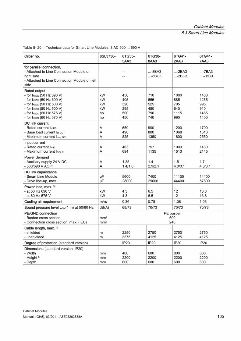
Cabinet Modules 5.3 Smart Line Modules
Cabinet Modules Manual, (GH5), 03/2011, A5E03263538A 165
Table 5- 20 Technical data for Smart Line Modules, 3 AC 500 ... 690 V
Order no. 6SL3730- 6TG35- 5AA3
6TG38- 8AA3
6TG41- 2AA3
6TG41- 7AA3
for parallel connection, - Attached to Line Connection Module on right side - Attached to Line Connection Module on left side
-- --
...-8BA3 ...-8BC3
...-2BA3 ...-2BC3
...-7BA3 ...-7BC3
Rated output - for IN DC (50 Hz 690 V) - for IH DC (50 Hz 690 V) - for IN DC (50 Hz 500 V) - for IH DC (50 Hz 500 V) - for IN DC (60 Hz 575 V) - for IH DC (60 Hz 575 V)
kW kW kW kW hp hp
450 405 320 295 500 450
710 665 525 480 790 740
1000 885 705 640 1115 990
1400 1255 995 910 1465 1400
DC link current - Rated current IN DC - Base load current IH DC1) - Maximum current Imax DC
A A A
550 490 825
900 800 1350
1200 1068 1800
1700 1513 2550
Input current - Rated current IN E - Maximum current Imax E
A A
463 694
757 1135
1009 1513
1430 2145
Power demand - Auxiliary supply 24 V DC - 500/690 V AC 2)
A A
1.35 1.4/1.0
1.4 2.9/2.1
1.5 4.3/3.1
1.7 4.3/3.1
DC link capacitance - Smart Line Module - Drive line-up, max.
µF µF
5600 28000
7400 29600
11100 44400
14400 57600
Power loss, max. 3) - at 50 Hz 690 V - at 60 Hz 575 V
kW kW
4.3 4.3
6.5 6.5
12 12
13.8 13.8
Cooling air requirement m3/s 0.36 0.78 1.08 1.08 Sound pressure level LpA (1 m) at 50/60 Hz dB(A) 69/73 70/73 70/73 70/73 PE/GND connection - Busbar cross section - Connection cross section, max. (IEC)
mm2
mm2
PE busbar 600 240
Cable length, max. 4) - shielded - unshielded
m m
2250 3375
2750 4125
2750 4125
2750 4125
Degree of protection (standard version) IP20 IP20 IP20 IP20 Dimensions (standard version, IP20) - Width - Height 5) - Depth
mm mm mm
400 2200 600
600 2200 600
800 2200 600
800 2200 600
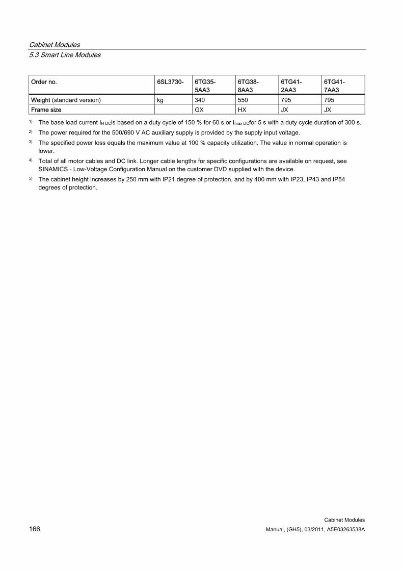
Cabinet Modules 5.3 Smart Line Modules
Cabinet Modules 166 Manual, (GH5), 03/2011, A5E03263538A
Order no. 6SL3730- 6TG35- 5AA3
6TG38- 8AA3
6TG41- 2AA3
6TG41- 7AA3
Weight (standard version) kg 340 550 795 795 Frame size GX HX JX JX
1) The base load current IH DCis based on a duty cycle of 150 % for 60 s or Imax DCfor 5 s with a duty cycle duration of 300 s. 2) The power required for the 500/690 V AC auxiliary supply is provided by the supply input voltage. 3) The specified power loss equals the maximum value at 100 % capacity utilization. The value in normal operation is
lower. 4) Total of all motor cables and DC link. Longer cable lengths for specific configurations are available on request, see
SINAMICS - Low-Voltage Configuration Manual on the customer DVD supplied with the device. 5) The cabinet height increases by 250 mm with IP21 degree of protection, and by 400 mm with IP23, IP43 and IP54
degrees of protection.
Cabinet Modules 5.4 Active Line Modules
Cabinet Modules Manual, (GH5), 03/2011, A5E03263538A 167
5.4 Active Line Modules
5.4.1 General information
DANGER
Hazardous voltages are present in certain parts of this equipment during operation of the cabinet unit. Only qualified personnel may work on the cabinet. Such personnel must be thoroughly familiar with all the warnings and maintenance procedures for the cabinet described in the documentation provided.
The successful and safe operation of this cabinet is dependent on correct transport, proper storage and installation, as well as careful operation and maintenance. National safety regulations must be observed.
5.4.2 Description
Note
Refer to the layout diagrams (AO) and circuit diagrams (SP) provided on the customer DVD supplied with the device for the arrangement of components and interfaces, and for wiring.
Active Line Modules can supply motoring energy and return regenerative energy to the supply system.
Active Line Modules generate a regulated DC voltage that is kept consistent regardless of fluctuations in the line voltage (the line voltage must range within the permissible tolerances).
In the factory setting, the DC voltage is controlled to 1.5 times the rms value of the rated line voltage.
Active Line Modules draw a virtually sinusoidal current from the supply system and cause virtually no line harmonic distortions.
Active Line Modules are suitable for connection to supply systems grounded at the neutral point (TN, TT) and non-grounded (IT) supply systems. The following voltages and power ratings are available:
Line voltage Rated power 380 to 480 V AC, 3-phase 132 ... 900 kW 500 to 690 V AC, 3-phase 560 ... 1400 kW
The power rating can be increased by connecting Active Line Modules in parallel.
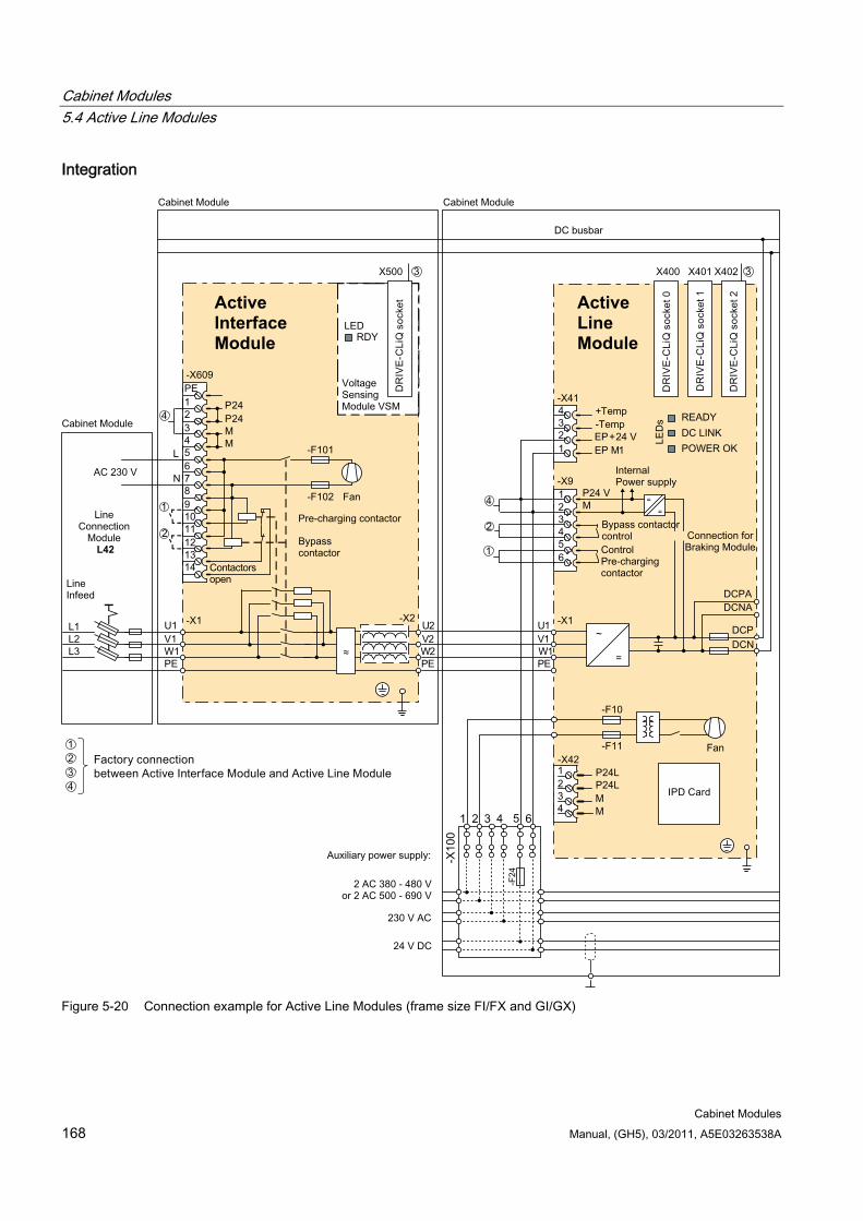
Cabinet Modules 5.4 Active Line Modules
Cabinet Modules 168 Manual, (GH5), 03/2011, A5E03263538A
Integration
Active Line Module
Active Interface Module
L42
Figure 5-20 Connection example for Active Line Modules (frame size FI/FX and GI/GX)
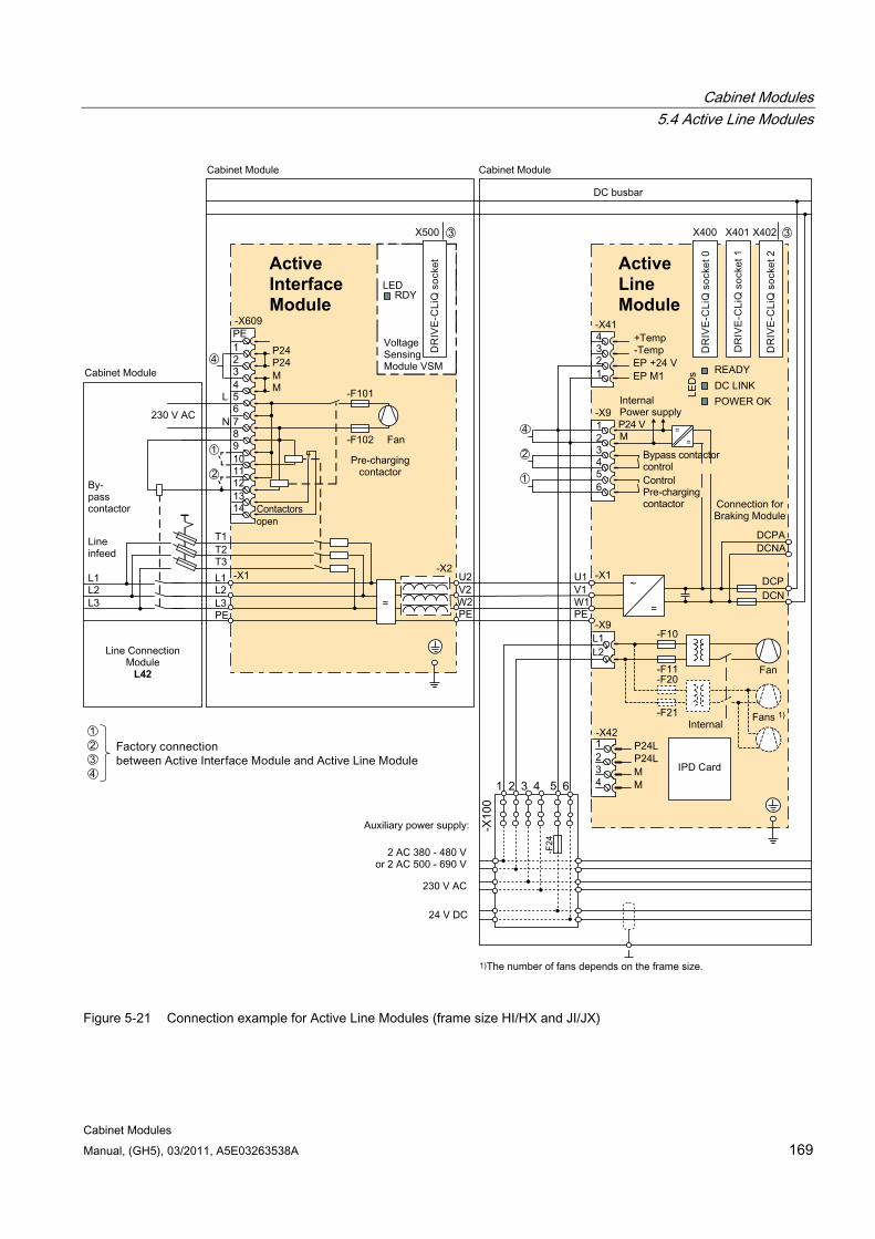
Cabinet Modules 5.4 Active Line Modules
Cabinet Modules Manual, (GH5), 03/2011, A5E03263538A 169
L42
Active Interface Module
Active Line Module
Figure 5-21 Connection example for Active Line Modules (frame size HI/HX and JI/JX)
Cabinet Modules 5.4 Active Line Modules
Cabinet Modules 170 Manual, (GH5), 03/2011, A5E03263538A
Configuration Active Line Modules are always operated together with an Active Interface Module, which contains the associated Clean Power Filter and pre-charging circuit. The included line filter enables compliance with the EMC requirements for the "second environment".
Note
The configuration examples of the individual Active Line Modules are used to illustrate the positioning of the factory-fitted components. They show the maximum possible configuration of the modules, which contain all options that can be ordered.
Refer to the layout diagrams (AO) on the customer DVD for the precise order-specific location of the components.
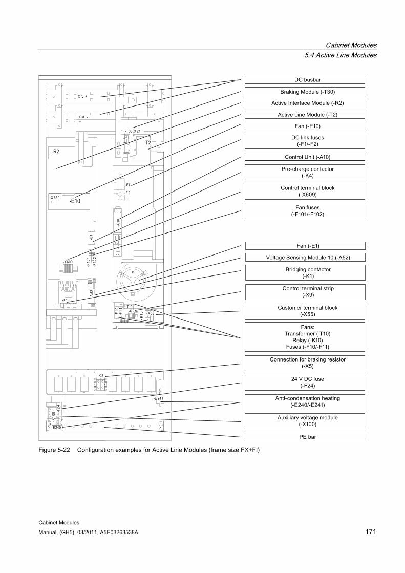
Cabinet Modules 5.4 Active Line Modules
Cabinet Modules Manual, (GH5), 03/2011, A5E03263538A 171
C /L +
D /L -
-X 630
-R2
-K 1
-X609
-F10
2-F
101
-A52
-K4
-E1
-T10
-F11
-F10 -X 9
-K10
-T2
AI _G
AIF
G rundblech AI F
-A10
-E240
-E 241
-X10
0 -F24
-X55
-X 5
-T 30 .X 21
PE
PE
- F1
-F 2
-E10
Figure 5-22 Configuration examples for Active Line Modules (frame size FX+FI)
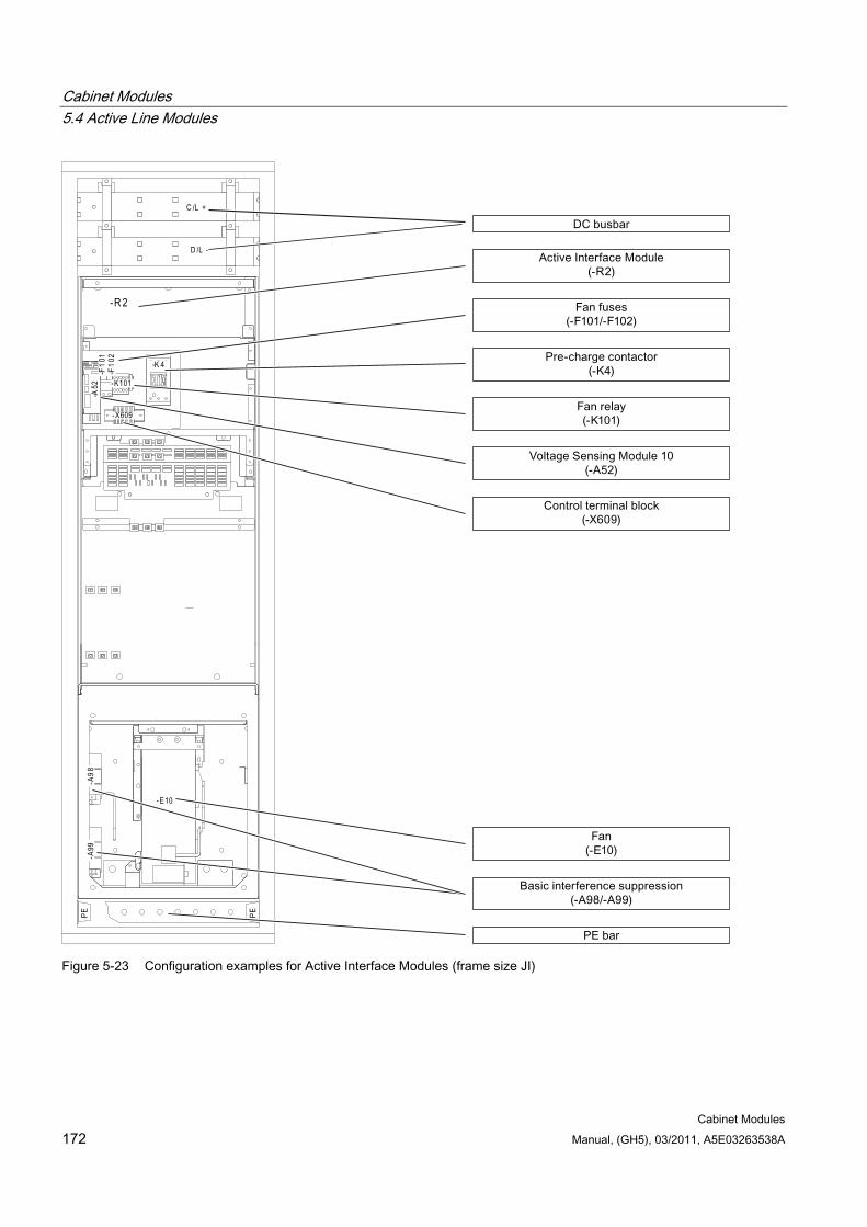
Cabinet Modules 5.4 Active Line Modules
Cabinet Modules 172 Manual, (GH5), 03/2011, A5E03263538A
C /L +
D /L -
-R 2
-A52
-F10
1-F
102
-X609
-K101
-K 4
-A98
-E10
-A99
PE PE
Figure 5-23 Configuration examples for Active Interface Modules (frame size JI)
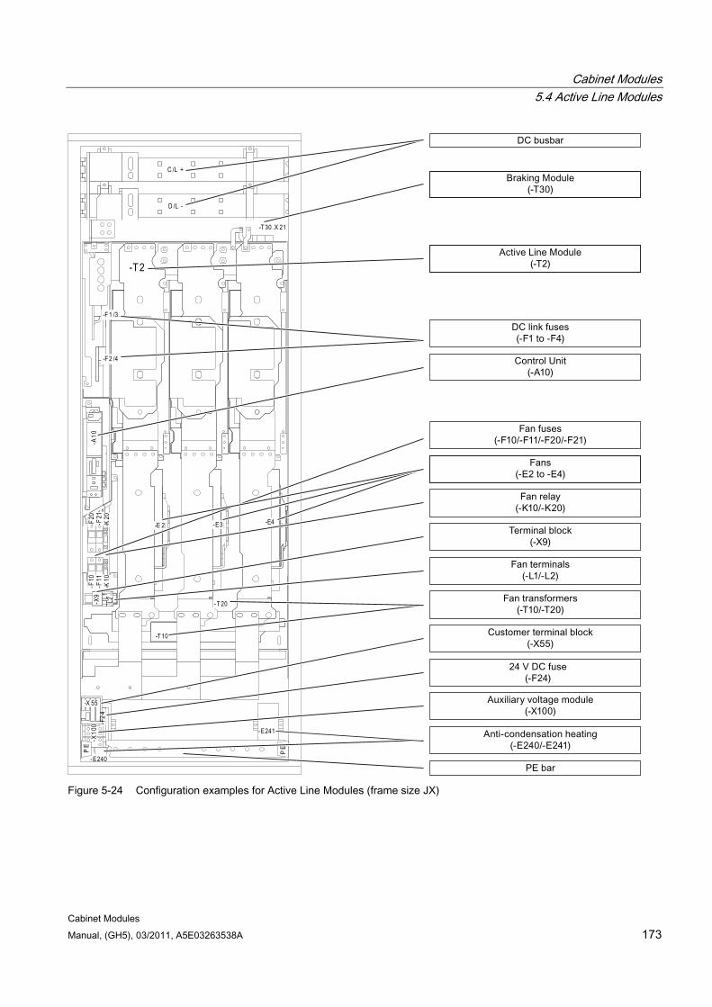
Cabinet Modules 5.4 Active Line Modules
Cabinet Modules Manual, (GH5), 03/2011, A5E03263538A 173
C /L +
D /L -
L1 L2-X9
-T 2
-E 2 -E3 -
-F 1 /3
-F 2 /4
-T 10
-T 20
-K20
-F20
-F21
-K10
-F10
-F11
-A10
-E240
-E241
-X10
0
-X 55
-T 30 .X 21
PE
PE
2-F
4
-E4
Figure 5-24 Configuration examples for Active Line Modules (frame size JX)
Cabinet Modules 5.4 Active Line Modules
Cabinet Modules 174 Manual, (GH5), 03/2011, A5E03263538A
Parallel connection of Active Line Modules to increase power rating Active Line Modules are available for creating drive line-ups with more power. These modules can be operated in parallel on a common Line Connection Module and are arranged to the right and left of the Line Connection Module. The power connections on the Active Line Module on the left of the Line Connection Module are a mirror image (device order number with C in the next-to-last position, example: 6SL3730-7Tx41x-xBC3a), which produces a very compact design for the supply infeed.
The following rules must be observed when connecting Active Line Modules in parallel:
Up to 4 identical Active Line Modules can be connected in parallel.
A common Control Unit is required whenever the modules are connected in parallel.
Special Line Connection Modules are available for connecting the modules in parallel.
With multiple infeeds, power must be supplied to the systems from a common infeed point (i.e. the modules cannot be operated on different supplies).
A derating factor of 5% must be taken into consideration, regardless of the number of modules connected in parallel.

Cabinet Modules 5.4 Active Line Modules
Cabinet Modules Manual, (GH5), 03/2011, A5E03263538A 175
5.4.3 Interface description
5.4.3.1 General information This chapter describes only those interfaces in the cabinet unit that require additional connection work by the customer. All other interfaces are pre-wired at the factory and are not designed for customer connections.
Note
All connections to be established on the plant side as well as the interfaces for integration into the plant control system are described in the circuit diagrams and terminal diagrams on the customer DVD supplied with the device.
5.4.3.2 Control Interface Module
Figure 5-25 Control Interface Module

Cabinet Modules 5.4 Active Line Modules
Cabinet Modules 176 Manual, (GH5), 03/2011, A5E03263538A
5.4.3.3 X41 EP terminal / temperature sensor connection
Table 5- 21 Terminal strip X41 EP terminals / temperature sensor connection
Terminal Function Technical specifications 1 EP M1 (Enable Pulses) 2 EP +24 V (Enable Pulses)
Supply voltage: 24 V DC (20.4 V...28.8 V) Power consumption: 10 mA
3 - Temp 4 + Temp
Temperature sensor connection: KTY84-1C130 / PTC
Max. connectable cross-section 1.5 mm2
Note
For operation, 24 V DC must be present at terminal 2 and ground at terminal 1. When removed, pulse suppression is activated.
DANGER Risk of electric shock!
Only temperature sensors that meet the electrical separation specifications stipulated in EN 61800-5-1 may be connected to terminals "+Temp" and "-Temp". If safe electrical separation cannot be guaranteed (for linear motors or third-party motors, for example), a Sensor Module External (SME120 or SME125) must be used.
If these instructions are not complied with, there is a risk of electric shock!
Note
The following sensors can be connected to the temperature sensor connection: KTY84-1C130 / PTC.
CAUTION The temperature sensor connection must be shielded. The shielding must be attached to the shield support of the module.
NOTICE The KTY temperature sensor must be connected with the correct polarity.

Cabinet Modules 5.4 Active Line Modules
Cabinet Modules Manual, (GH5), 03/2011, A5E03263538A 177
5.4.3.4 DRIVE-CLiQ interfaces X400, X401, X402
Table 5- 22 DRIVE-CLiQ interfaces X400, X401, X402
PIN Signal name Technical specifications 1 TXP Transmit data + 2 TXN Transmit data - 3 RXP Receive data + 4 Reserved, do not use 5 Reserved, do not use 6 RXN Receive data - 7 Reserved, do not use 8 Reserved, do not use A + (24 V) 24 V power supply
B M (0 V) Electronics ground Blanking plate for DRIVE-CLiQ interfaces (50 pcs.) order number: 6SL3066-4CA00-0AA0

Cabinet Modules 5.4 Active Line Modules
Cabinet Modules 178 Manual, (GH5), 03/2011, A5E03263538A
5.4.4 Options
Note
The individual options are described in the chapter titled "Options".
Electrical options Component Option CBC10 Communication Board G20 CBE20 Communication Board G33 Customer terminal block G55 Contactor feedback signal G56 AOP30 operator panel K08 Control Unit CU320-2 PROFIBUS K90 Performance extension for CU320-2 K94 Control Unit CU320-2 PROFINET K95 Use in the first environment to EN 61800-3, category C2 (TN/TT line supplies)
L00
Holder for ARC detector L51 Cabinet anti-condensation heating L55 25/125 kW braking unit L61/L64 50/250 kW braking unit L62/L65
Mechanical options Component Option Base 100 mm high M06 Cable-marshaling compartment 200 mm high M07 IP21 degree of protection M21 IP23/IP43/IP54 degree of protection M23, M43, M54 Side panels (right/left) M26, M27 Closed cabinet door M59 Additional shock protection M60 DC busbar M80 ... M87 Crane transport assembly (top-mounted) M90
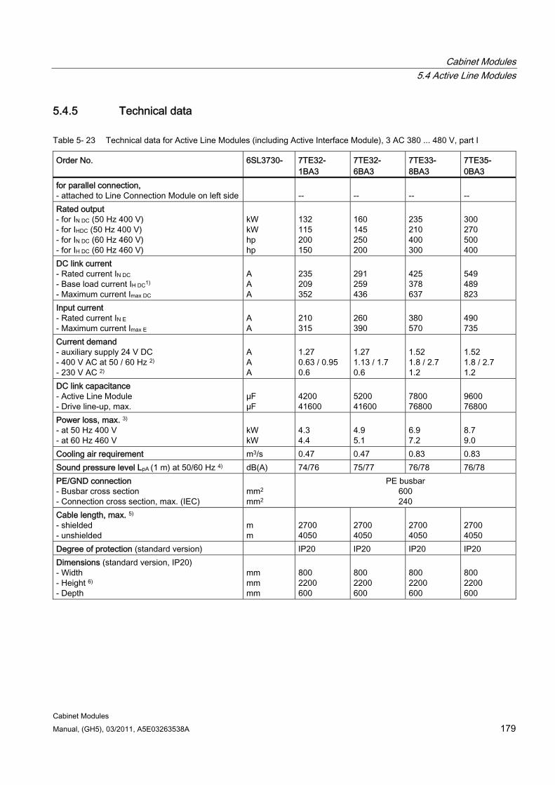
Cabinet Modules 5.4 Active Line Modules
Cabinet Modules Manual, (GH5), 03/2011, A5E03263538A 179
5.4.5 Technical data
Table 5- 23 Technical data for Active Line Modules (including Active Interface Module), 3 AC 380 ... 480 V, part I
Order No. 6SL3730- 7TE32- 1BA3
7TE32- 6BA3
7TE33- 8BA3
7TE35- 0BA3
for parallel connection, - attached to Line Connection Module on left side
--
--
--
--
Rated output - for IN DC (50 Hz 400 V) - for IHDC (50 Hz 400 V) - for IN DC (60 Hz 460 V) - for IH DC (60 Hz 460 V)
kW kW hp hp
132 115 200 150
160 145 250 200
235 210 400 300
300 270 500 400
DC link current - Rated current IN DC - Base load current IH DC1) - Maximum current Imax DC
A A A
235 209 352
291 259 436
425 378 637
549 489 823
Input current - Rated current IN E - Maximum current Imax E
A A
210 315
260 390
380 570
490 735
Current demand - auxiliary supply 24 V DC - 400 V AC at 50 / 60 Hz 2) - 230 V AC 2)
A A A
1.27 0.63 / 0.95 0.6
1.27 1.13 / 1.7 0.6
1.52 1.8 / 2.7 1.2
1.52 1.8 / 2.7 1.2
DC link capacitance - Active Line Module - Drive line-up, max.
µF µF
4200 41600
5200 41600
7800 76800
9600 76800
Power loss, max. 3) - at 50 Hz 400 V - at 60 Hz 460 V
kW kW
4.3 4.4
4.9 5.1
6.9 7.2
8.7 9.0
Cooling air requirement m3/s 0.47 0.47 0.83 0.83 Sound pressure level LpA (1 m) at 50/60 Hz 4) dB(A) 74/76 75/77 76/78 76/78 PE/GND connection - Busbar cross section - Connection cross section, max. (IEC)
mm2
mm2
PE busbar 600 240
Cable length, max. 5) - shielded - unshielded
m m
2700 4050
2700 4050
2700 4050
2700 4050
Degree of protection (standard version) IP20 IP20 IP20 IP20 Dimensions (standard version, IP20) - Width - Height 6) - Depth
mm mm mm
800 2200 600
800 2200 600
800 2200 600
800 2200 600
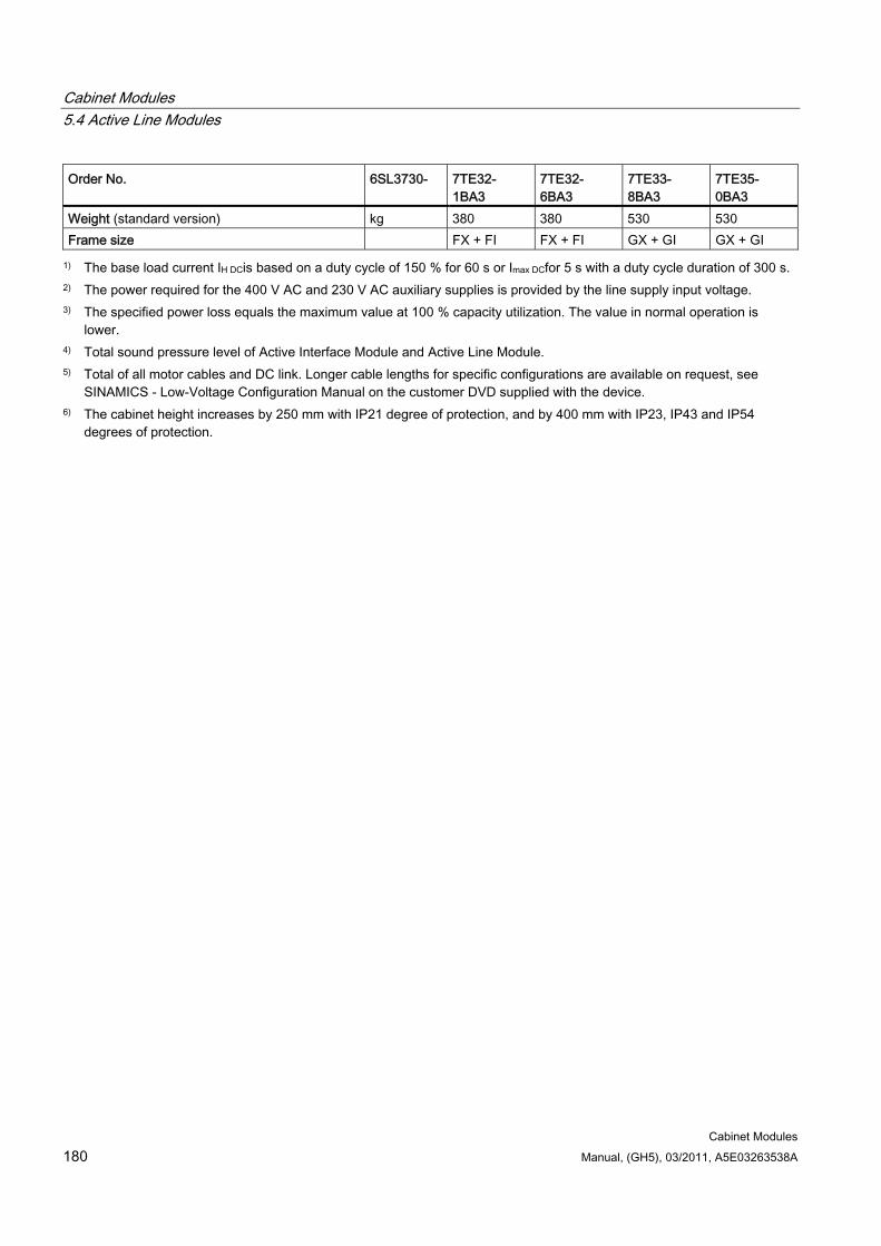
Cabinet Modules 5.4 Active Line Modules
Cabinet Modules 180 Manual, (GH5), 03/2011, A5E03263538A
Order No. 6SL3730- 7TE32- 1BA3
7TE32- 6BA3
7TE33- 8BA3
7TE35- 0BA3
Weight (standard version) kg 380 380 530 530 Frame size FX + FI FX + FI GX + GI GX + GI
1) The base load current IH DCis based on a duty cycle of 150 % for 60 s or Imax DCfor 5 s with a duty cycle duration of 300 s. 2) The power required for the 400 V AC and 230 V AC auxiliary supplies is provided by the line supply input voltage. 3) The specified power loss equals the maximum value at 100 % capacity utilization. The value in normal operation is
lower. 4) Total sound pressure level of Active Interface Module and Active Line Module. 5) Total of all motor cables and DC link. Longer cable lengths for specific configurations are available on request, see
SINAMICS - Low-Voltage Configuration Manual on the customer DVD supplied with the device. 6) The cabinet height increases by 250 mm with IP21 degree of protection, and by 400 mm with IP23, IP43 and IP54
degrees of protection.
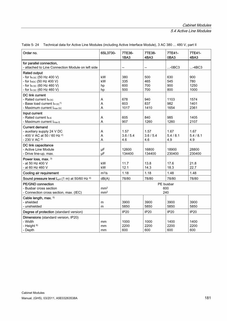
Cabinet Modules 5.4 Active Line Modules
Cabinet Modules Manual, (GH5), 03/2011, A5E03263538A 181
Table 5- 24 Technical data for Active Line Modules (including Active Interface Module), 3 AC 380 ... 480 V, part II
Order no. 6SL3730- 7TE36- 1BA3
7TE38- 4BA3
7TE41- 0BA3
7TE41- 4BA3
for parallel connection, - attached to Line Connection Module on left side
--
--
...-0BC3
...-4BC3
Rated output - for IN DC (50 Hz 400 V) - for IHDC (50 Hz 400 V) - for IN DC (60 Hz 460 V) - for IH DC (60 Hz 460 V)
kW kW hp hp
380 335 600 500
500 465 700 700
630 545 900 800
900 780 1250 1000
DC link current - Rated current IN DC - Base load current IH DC1) - Maximum current Imax DC
A A A
678 603 1017
940 837 1410
1103 982 1654
1574 1401 2361
Input current - Rated current IN E - Maximum current Imax E
A A
605 907
840 1260
985 1260
1405 2107
Current demand - auxiliary supply 24 V DC - 400 V AC at 50 / 60 Hz 2) - 230 V AC 2)
A A A
1.57 3.6 / 5.4 4.6
1.57 3.6 / 5.4 4.6
1.67 5.4 / 8.1 4.9
1.67 5.4 / 8.1 4.9
DC link capacitance - Active Line Module - Drive line-up, max.
µF µF
12600 134400
16800 134400
18900 230400
28800 230400
Power loss, max. 3) - at 50 Hz 400 V - at 60 Hz 460 V
kW kW
11.7 12.1
13.8 14.3
17.6 18.3
21.8 22.7
Cooling air requirement m3/s 1.18 1.18 1.48 1.48 Sound pressure level LpA (1 m) at 50/60 Hz 4) dB(A) 78/80 78/80 78/80 78/80 PE/GND connection - Busbar cross section - Connection cross section, max. (IEC)
mm2
mm2
PE busbar 600 240
Cable length, max. 5) - shielded - unshielded
m m
3900 5850
3900 5850
3900 5850
3900 5850
Degree of protection (standard version) IP20 IP20 IP20 IP20 Dimensions (standard version, IP20) - Width - Height 6) - Depth
mm mm mm
1000 2200 600
1000 2200 600
1400 2200 600
1400 2200 600

Cabinet Modules 5.4 Active Line Modules
Cabinet Modules 182 Manual, (GH5), 03/2011, A5E03263538A
Order no. 6SL3730- 7TE36- 1BA3
7TE38- 4BA3
7TE41- 0BA3
7TE41- 4BA3
Weight (standard version) kg 930 930 1360 1360 Frame size HX + HI HX + HI JX + JI JX + JI
1) The base load current IH DCis based on a duty cycle of 150 % for 60 s or Imax DCfor 5 s with a duty cycle duration of 300 s. 2) The power required for the 400 V AC and 230 V AC auxiliary supplies is provided by the line supply input voltage. 3) The specified power loss equals the maximum value at 100 % capacity utilization. The value in normal operation is
lower. 4) Total sound pressure level of Active Interface Module and Active Line Module. 5) Total of all motor cables and DC link. Longer cable lengths for specific configurations are available on request, see
SINAMICS - Low-Voltage Configuration Manual on the customer DVD supplied with the device. 6) The cabinet height increases by 250 mm with IP21 degree of protection, and by 400 mm with IP23, IP43 and IP54
degrees of protection.
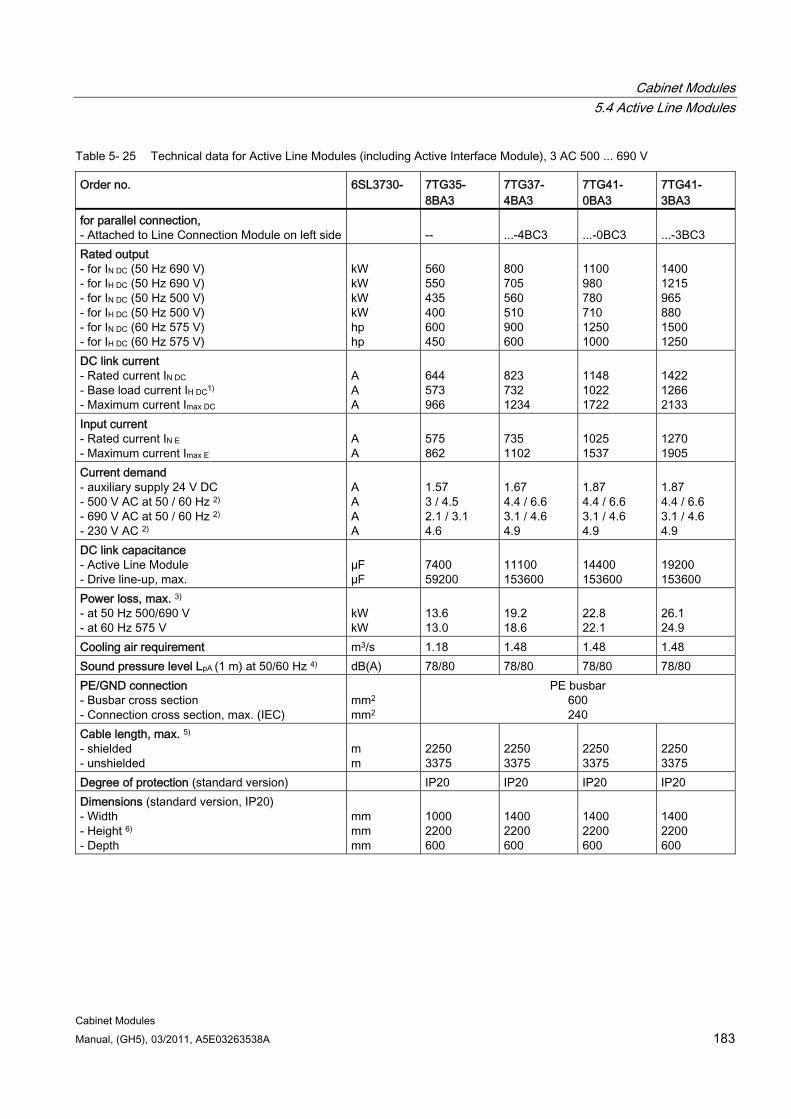
Cabinet Modules 5.4 Active Line Modules
Cabinet Modules Manual, (GH5), 03/2011, A5E03263538A 183
Table 5- 25 Technical data for Active Line Modules (including Active Interface Module), 3 AC 500 ... 690 V
Order no. 6SL3730- 7TG35- 8BA3
7TG37- 4BA3
7TG41- 0BA3
7TG41- 3BA3
for parallel connection, - Attached to Line Connection Module on left side
--
...-4BC3
...-0BC3
...-3BC3
Rated output - for IN DC (50 Hz 690 V) - for IH DC (50 Hz 690 V) - for IN DC (50 Hz 500 V) - for IH DC (50 Hz 500 V) - for IN DC (60 Hz 575 V) - for IH DC (60 Hz 575 V)
kW kW kW kW hp hp
560 550 435 400 600 450
800 705 560 510 900 600
1100 980 780 710 1250 1000
1400 1215 965 880 1500 1250
DC link current - Rated current IN DC - Base load current IH DC1) - Maximum current Imax DC
A A A
644 573 966
823 732 1234
1148 1022 1722
1422 1266 2133
Input current - Rated current IN E - Maximum current Imax E
A A
575 862
735 1102
1025 1537
1270 1905
Current demand - auxiliary supply 24 V DC - 500 V AC at 50 / 60 Hz 2) - 690 V AC at 50 / 60 Hz 2) - 230 V AC 2)
A A A A
1.57 3 / 4.5 2.1 / 3.1 4.6
1.67 4.4 / 6.6 3.1 / 4.6 4.9
1.87 4.4 / 6.6 3.1 / 4.6 4.9
1.87 4.4 / 6.6 3.1 / 4.6 4.9
DC link capacitance - Active Line Module - Drive line-up, max.
µF µF
7400 59200
11100 153600
14400 153600
19200 153600
Power loss, max. 3) - at 50 Hz 500/690 V - at 60 Hz 575 V
kW kW
13.6 13.0
19.2 18.6
22.8 22.1
26.1 24.9
Cooling air requirement m3/s 1.18 1.48 1.48 1.48 Sound pressure level LpA (1 m) at 50/60 Hz 4) dB(A) 78/80 78/80 78/80 78/80 PE/GND connection - Busbar cross section - Connection cross section, max. (IEC)
mm2
mm2
PE busbar 600 240
Cable length, max. 5) - shielded - unshielded
m m
2250 3375
2250 3375
2250 3375
2250 3375
Degree of protection (standard version) IP20 IP20 IP20 IP20 Dimensions (standard version, IP20) - Width - Height 6) - Depth
mm mm mm
1000 2200 600
1400 2200 600
1400 2200 600
1400 2200 600
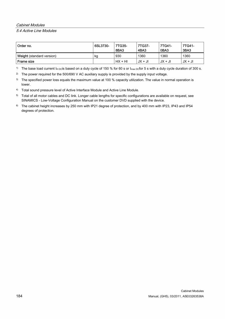
Cabinet Modules 5.4 Active Line Modules
Cabinet Modules 184 Manual, (GH5), 03/2011, A5E03263538A
Order no. 6SL3730- 7TG35- 8BA3
7TG37- 4BA3
7TG41- 0BA3
7TG41- 3BA3
Weight (standard version) kg 930 1360 1360 1360 Frame size HX + HI JX + JI JX + JI JX + JI
1) The base load current IH DCis based on a duty cycle of 150 % for 60 s or Imax DCfor 5 s with a duty cycle duration of 300 s. 2) The power required for the 500/690 V AC auxiliary supply is provided by the supply input voltage. 3) The specified power loss equals the maximum value at 100 % capacity utilization. The value in normal operation is
lower. 4) Total sound pressure level of Active Interface Module and Active Line Module. 5) Total of all motor cables and DC link. Longer cable lengths for specific configurations are available on request, see
SINAMICS - Low-Voltage Configuration Manual on the customer DVD supplied with the device. 6) The cabinet height increases by 250 mm with IP21 degree of protection, and by 400 mm with IP23, IP43 and IP54
degrees of protection.

Cabinet Modules 5.5 Booksize format Motor Modules
Cabinet Modules Manual, (GH5), 03/2011, A5E03263538A 185
5.5 Booksize format Motor Modules
5.5.1 General information
DANGER
Hazardous voltages are present in certain parts of this equipment during operation of the cabinet unit. Only qualified personnel may work on the cabinet. Such personnel must be thoroughly familiar with all the warnings and maintenance procedures for the cabinet described in the documentation provided.
The successful and safe operation of this cabinet is dependent on correct transport, proper storage and installation, as well as careful operation and maintenance. National safety regulations must be observed.
WARNING Do not switch off the fuse switch disconnector under load. Restarting the fuse switch disconnector when the DC busbar is live can cause damage to the device. You can only restart the fuse switch disconnector with the option L37 (DC interface).
5.5.2 Description
Note
Refer to the layout diagrams (AO) and circuit diagrams (SP) provided on the customer DVD supplied with the device for the arrangement of components and interfaces, and for wiring.
Motor Modules are also available in a Booksize Cabinet Kit version for power ratings from 1.6 to 107 kW in voltage class 380 to 480 V (DC link voltage 510 to 720 V).
Single Motor Modules are available for connection of one motor, and Double Motor Modules (in power rating range 1.6 to 9.7 kW) are available for connection of two motors.
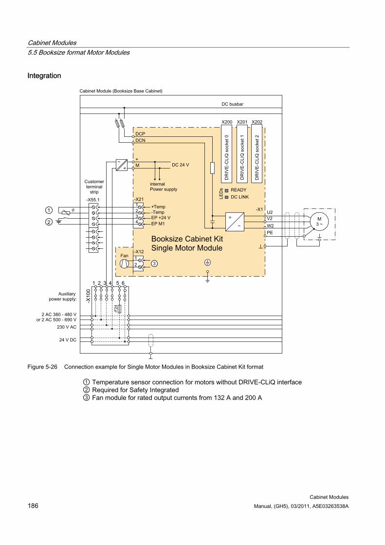
Cabinet Modules 5.5 Booksize format Motor Modules
Cabinet Modules 186 Manual, (GH5), 03/2011, A5E03263538A
Integration
Figure 5-26 Connection example for Single Motor Modules in Booksize Cabinet Kit format
① Temperature sensor connection for motors without DRIVE-CLiQ interface ② Required for Safety Integrated ③ Fan module for rated output currents from 132 A and 200 A
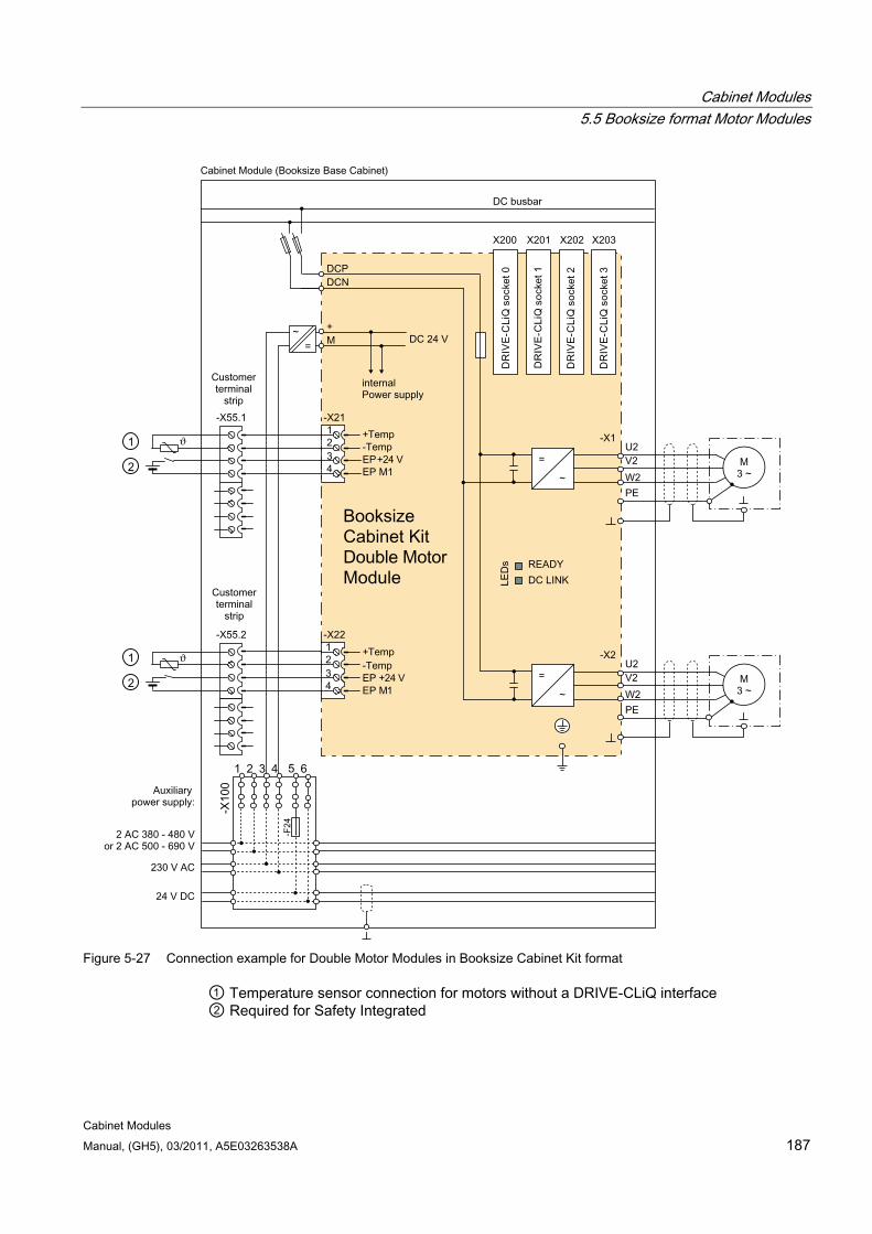
Cabinet Modules 5.5 Booksize format Motor Modules
Cabinet Modules Manual, (GH5), 03/2011, A5E03263538A 187
Figure 5-27 Connection example for Double Motor Modules in Booksize Cabinet Kit format
① Temperature sensor connection for motors without a DRIVE-CLiQ interface ② Required for Safety Integrated
Cabinet Modules 5.5 Booksize format Motor Modules
Cabinet Modules 188 Manual, (GH5), 03/2011, A5E03263538A
Configuration Motor Modules in booksize format are factory-installed as "Booksize Cabinet Kits" in Booksize Base Cabinets and delivered as a complete unit including cabinet-side connection components.
Several Booksize Cabinet Kits can be installed in one Booksize Base Cabinet, depending on the mounting width requirements, which in turn depend on the power. Each Motor Module is connected separately to the DC busbar of the Cabinet Modules via a separate fuse switch disconnector. The DC link rail integrated in the devices is not used. As a 24 V DC supply buffered by the DC link is not possible for Booksize units, a dedicated SITOP is used to provide the 24 V DC required for the Booksize Cabinet Kit.
Note
The configuration examples of the individual Motor Modules are used to illustrate the positioning of the factory-fitted components. They show the maximum possible configuration of the modules, which contain all options that can be ordered.
Refer to the layout diagrams (AO) on the customer DVD for the precise order-specific location of the components.
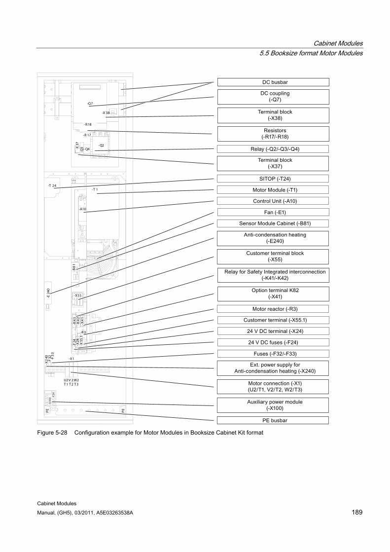
Cabinet Modules 5.5 Booksize format Motor Modules
Cabinet Modules Manual, (GH5), 03/2011, A5E03263538A 189
-X10
0 -F24
600
C /L +
D/L -
-X2
40-F
32 -F3
3
-X2
4
-E24
0P
E
PE
-T 24-T 1
blech
hut
C U bl
-Q7
-X 38
-Q2-Q4
-Q3-X
37
-R18
-R 17
-B8
1
-X55
-K4
1-K
42
-X4
1
-F24
-X24
-X55
.1
-X1
U2T 1
V 2T 2
W2T 3
-A1
0
-A10
-R3
Figure 5-28 Configuration example for Motor Modules in Booksize Cabinet Kit format
Cabinet Modules 5.5 Booksize format Motor Modules
Cabinet Modules 190 Manual, (GH5), 03/2011, A5E03263538A
Mounting grid arrangement in the cabinet The area for connecting the Motor Modules in the cabinet is divided into three grid widths:
100 mm
200 mm
300 mm
The table below shows the grid width assigned to the various Motor Modules.
Table 5- 26 The assignment of the Motor Modules according to grid width
Grid width Assignment of Motor Modules (see the section titled "Technical data") 100 mm 3 to 30 A Single Motor Modules 200 mm 45 to 85 A Single Motor Modules, 3 to 18 A Double Motor Modules 300 mm 132 ... 200 A Single Motor Module
Note
The space available for the Motor Modules in the Booksize Base Cabinets is determined by taking the actual space and subtracting a clearance of 200 mm.
Cabinet Modules 5.5 Booksize format Motor Modules
Cabinet Modules Manual, (GH5), 03/2011, A5E03263538A 191
5.5.3 Interface description
5.5.3.1 General information This chapter describes only those interfaces in the cabinet unit that require additional connection work by the customer. All other interfaces are pre-wired at the factory and are not designed for customer connections.
Note
All connections to be established on the plant side as well as the interfaces for integration into the plant control system are described in the circuit diagrams and terminal diagrams on the customer DVD supplied with the device.
5.5.3.2 Customer terminal block X55.1
Description The customer terminal block (-X55.1) is mounted as standard in the cabinet for each Booksize Cabinet Kit. It provides the function-related inputs/outputs for temperature monitoring and for the "Safe Torque Off" and "Safe Stop 1" functions.
Note
All other cabinet interfaces and connections are explained in the circuit and terminal diagrams on the customer DVD supplied.
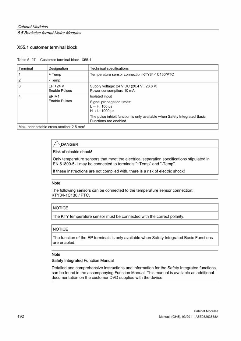
Cabinet Modules 5.5 Booksize format Motor Modules
Cabinet Modules 192 Manual, (GH5), 03/2011, A5E03263538A
X55.1 customer terminal block
Table 5- 27 Customer terminal block -X55.1
Terminal Designation Technical specifications 1 + Temp 2 - Temp
Temperature sensor connection KTY84-1C130/PTC
3 EP +24 V Enable Pulses
4 EP M1 Enable Pulses
Supply voltage: 24 V DC (20.4 V...28.8 V) Power consumption: 10 mA Isolated input Signal propagation times: L → H: 100 µs H → L: 1000 µs The pulse inhibit function is only available when Safety Integrated Basic Functions are enabled.
Max. connectable cross-section: 2.5 mm2
DANGER Risk of electric shock!
Only temperature sensors that meet the electrical separation specifications stipulated in EN 61800-5-1 may be connected to terminals "+Temp" and "-Temp".
If these instructions are not complied with, there is a risk of electric shock!
Note
The following sensors can be connected to the temperature sensor connection: KTY84-1C130 / PTC.
NOTICE The KTY temperature sensor must be connected with the correct polarity.
NOTICE The function of the EP terminals is only available when Safety Integrated Basic Functions are enabled.
Note Safety Integrated Function Manual
Detailed and comprehensive instructions and information for the Safety Integrated functions can be found in the accompanying Function Manual. This manual is available as additional documentation on the customer DVD supplied with the device.
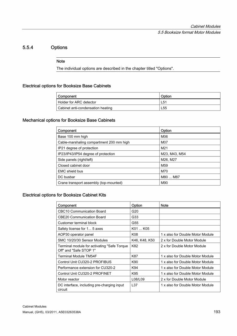
Cabinet Modules 5.5 Booksize format Motor Modules
Cabinet Modules Manual, (GH5), 03/2011, A5E03263538A 193
5.5.4 Options
Note
The individual options are described in the chapter titled "Options".
Electrical options for Booksize Base Cabinets Component Option Holder for ARC detector L51 Cabinet anti-condensation heating L55
Mechanical options for Booksize Base Cabinets Component Option Base 100 mm high M06 Cable-marshaling compartment 200 mm high M07 IP21 degree of protection M21 IP23/IP43/IP54 degree of protection M23, M43, M54 Side panels (right/left) M26, M27 Closed cabinet door M59 EMC shield bus M70 DC busbar M80 ... M87 Crane transport assembly (top-mounted) M90
Electrical options for Booksize Cabinet Kits Component Option Note CBC10 Communication Board G20 CBE20 Communication Board G33 Customer terminal block G55 Safety license for 1... 5 axes K01 ... K05 AOP30 operator panel K08 1 x also for Double Motor Module SMC 10/20/30 Sensor Modules K46, K48, K50 2 x for Double Motor Module Terminal module for activating "Safe Torque Off" and "Safe STOP 1"
K82 2 x for Double Motor Module
Terminal Module TM54F K87 1 x also for Double Motor Module Control Unit CU320-2 PROFIBUS K90 1 x also for Double Motor Module Performance extension for CU320-2 K94 1 x also for Double Motor Module Control Unit CU320-2 PROFINET K95 1 x also for Double Motor Module Motor reactor L08/L09 2 x for Double Motor Module DC interface, including pre-charging input circuit
L37 1 x also for Double Motor Module
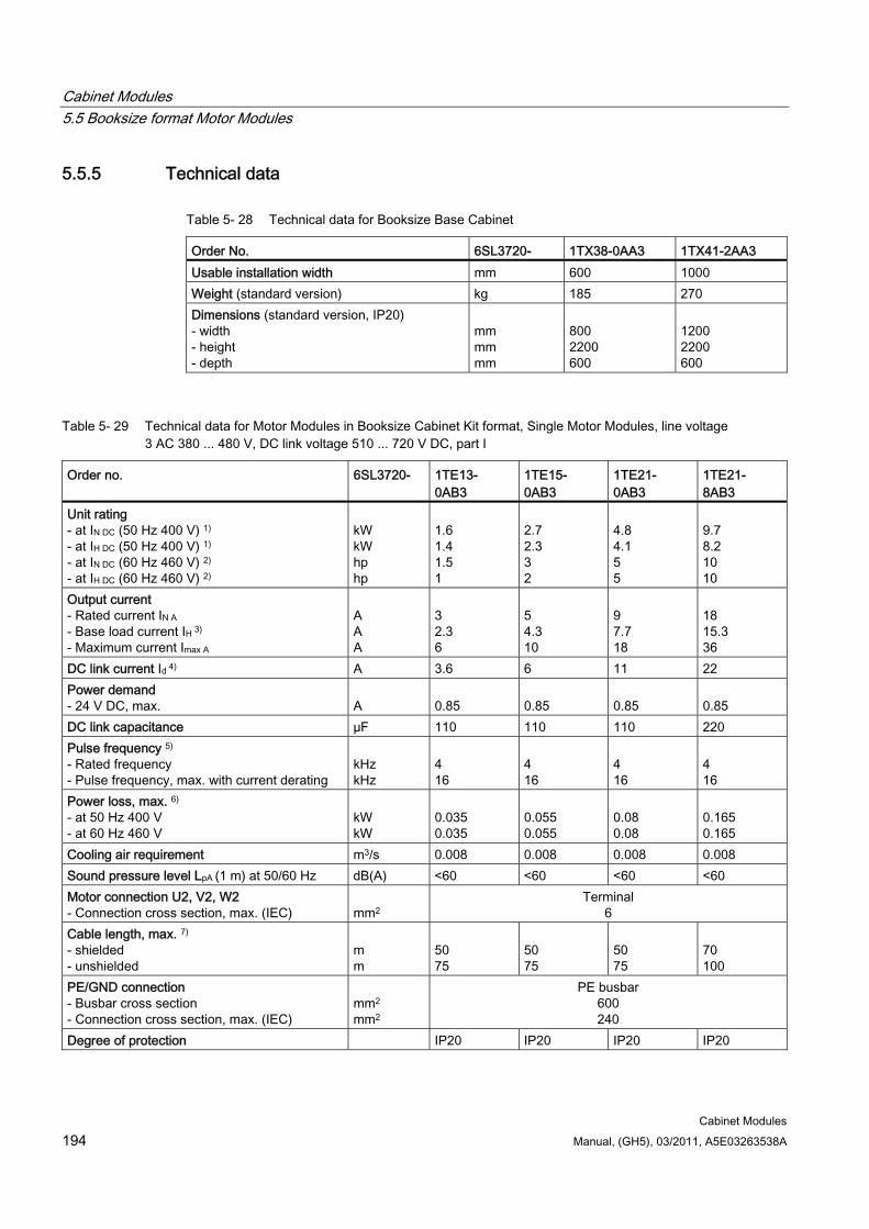
Cabinet Modules 5.5 Booksize format Motor Modules
Cabinet Modules 194 Manual, (GH5), 03/2011, A5E03263538A
5.5.5 Technical data
Table 5- 28 Technical data for Booksize Base Cabinet
Order No. 6SL3720- 1TX38-0AA3 1TX41-2AA3 Usable installation width mm 600 1000 Weight (standard version) kg 185 270 Dimensions (standard version, IP20) - width - height - depth
mm mm mm
800 2200 600
1200 2200 600
Table 5- 29 Technical data for Motor Modules in Booksize Cabinet Kit format, Single Motor Modules, line voltage 3 AC 380 ... 480 V, DC link voltage 510 ... 720 V DC, part I
Order no. 6SL3720- 1TE13- 0AB3
1TE15- 0AB3
1TE21- 0AB3
1TE21- 8AB3
Unit rating - at IN DC (50 Hz 400 V) 1) - at IH DC (50 Hz 400 V) 1) - at IN DC (60 Hz 460 V) 2) - at IH DC (60 Hz 460 V) 2)
kW kW hp hp
1.6 1.4 1.5 1
2.7 2.3 3 2
4.8 4.1 5 5
9.7 8.2 10 10
Output current - Rated current IN A - Base load current IH 3) - Maximum current Imax A
A A A
3 2.3 6
5 4.3 10
9 7.7 18
18 15.3 36
DC link current Id 4) A 3.6 6 11 22 Power demand - 24 V DC, max.
A
0.85
0.85
0.85
0.85
DC link capacitance µF 110 110 110 220 Pulse frequency 5) - Rated frequency - Pulse frequency, max. with current derating
kHz kHz
4 16
4 16
4 16
4 16
Power loss, max. 6) - at 50 Hz 400 V - at 60 Hz 460 V
kW kW
0.035 0.035
0.055 0.055
0.08 0.08
0.165 0.165
Cooling air requirement m3/s 0.008 0.008 0.008 0.008 Sound pressure level LpA (1 m) at 50/60 Hz dB(A) <60 <60 <60 <60 Motor connection U2, V2, W2 - Connection cross section, max. (IEC)
mm2
Terminal 6
Cable length, max. 7) - shielded - unshielded
m m
50 75
50 75
50 75
70 100
PE/GND connection - Busbar cross section - Connection cross section, max. (IEC)
mm2
mm2
PE busbar 600 240
Degree of protection IP20 IP20 IP20 IP20
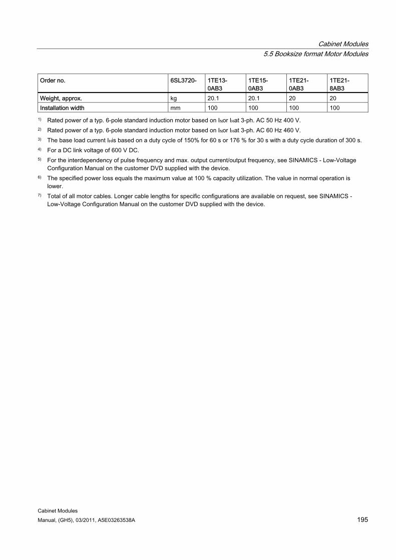
Cabinet Modules 5.5 Booksize format Motor Modules
Cabinet Modules Manual, (GH5), 03/2011, A5E03263538A 195
Order no. 6SL3720- 1TE13- 0AB3
1TE15- 0AB3
1TE21- 0AB3
1TE21- 8AB3
Weight, approx. kg 20.1 20.1 20 20 Installation width mm 100 100 100 100
1) Rated power of a typ. 6-pole standard induction motor based on INor IHat 3-ph. AC 50 Hz 400 V. 2) Rated power of a typ. 6-pole standard induction motor based on INor IHat 3-ph. AC 60 Hz 460 V. 3) The base load current IHis based on a duty cycle of 150% for 60 s or 176 % for 30 s with a duty cycle duration of 300 s. 4) For a DC link voltage of 600 V DC. 5) For the interdependency of pulse frequency and max. output current/output frequency, see SINAMICS - Low-Voltage
Configuration Manual on the customer DVD supplied with the device. 6) The specified power loss equals the maximum value at 100 % capacity utilization. The value in normal operation is
lower. 7) Total of all motor cables. Longer cable lengths for specific configurations are available on request, see SINAMICS -
Low-Voltage Configuration Manual on the customer DVD supplied with the device.
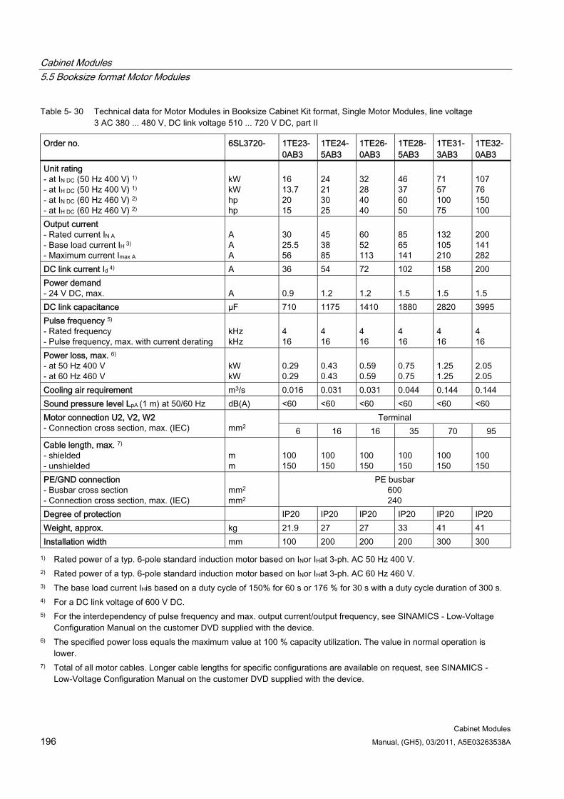
Cabinet Modules 5.5 Booksize format Motor Modules
Cabinet Modules 196 Manual, (GH5), 03/2011, A5E03263538A
Table 5- 30 Technical data for Motor Modules in Booksize Cabinet Kit format, Single Motor Modules, line voltage 3 AC 380 ... 480 V, DC link voltage 510 ... 720 V DC, part II
Order no. 6SL3720- 1TE23-0AB3
1TE24-5AB3
1TE26-0AB3
1TE28-5AB3
1TE31-3AB3
1TE32-0AB3
Unit rating - at IN DC (50 Hz 400 V) 1) - at IH DC (50 Hz 400 V) 1) - at IN DC (60 Hz 460 V) 2) - at IH DC (60 Hz 460 V) 2)
kW kW hp hp
16 13.7 20 15
24 21 30 25
32 28 40 40
46 37 60 50
71 57 100 75
107 76 150 100
Output current - Rated current IN A - Base load current IH 3) - Maximum current Imax A
A A A
30 25.5 56
45 38 85
60 52 113
85 65 141
132 105 210
200 141 282
DC link current Id 4) A 36 54 72 102 158 200 Power demand - 24 V DC, max.
A
0.9
1.2
1.2
1.5
1.5
1.5
DC link capacitance µF 710 1175 1410 1880 2820 3995 Pulse frequency 5) - Rated frequency - Pulse frequency, max. with current derating
kHz kHz
4 16
4 16
4 16
4 16
4 16
4 16
Power loss, max. 6) - at 50 Hz 400 V - at 60 Hz 460 V
kW kW
0.29 0.29
0.43 0.43
0.59 0.59
0.75 0.75
1.25 1.25
2.05 2.05
Cooling air requirement m3/s 0.016 0.031 0.031 0.044 0.144 0.144 Sound pressure level LpA (1 m) at 50/60 Hz dB(A) <60 <60 <60 <60 <60 <60
Terminal Motor connection U2, V2, W2 - Connection cross section, max. (IEC)
mm2 6 16 16 35 70 95
Cable length, max. 7) - shielded - unshielded
m m
100 150
100 150
100 150
100 150
100 150
100 150
PE/GND connection - Busbar cross section - Connection cross section, max. (IEC)
mm2
mm2
PE busbar 600 240
Degree of protection IP20 IP20 IP20 IP20 IP20 IP20 Weight, approx. kg 21.9 27 27 33 41 41 Installation width mm 100 200 200 200 300 300
1) Rated power of a typ. 6-pole standard induction motor based on INor IHat 3-ph. AC 50 Hz 400 V. 2) Rated power of a typ. 6-pole standard induction motor based on INor IHat 3-ph. AC 60 Hz 460 V. 3) The base load current IHis based on a duty cycle of 150% for 60 s or 176 % for 30 s with a duty cycle duration of 300 s. 4) For a DC link voltage of 600 V DC. 5) For the interdependency of pulse frequency and max. output current/output frequency, see SINAMICS - Low-Voltage
Configuration Manual on the customer DVD supplied with the device. 6) The specified power loss equals the maximum value at 100 % capacity utilization. The value in normal operation is
lower. 7) Total of all motor cables. Longer cable lengths for specific configurations are available on request, see SINAMICS -
Low-Voltage Configuration Manual on the customer DVD supplied with the device.
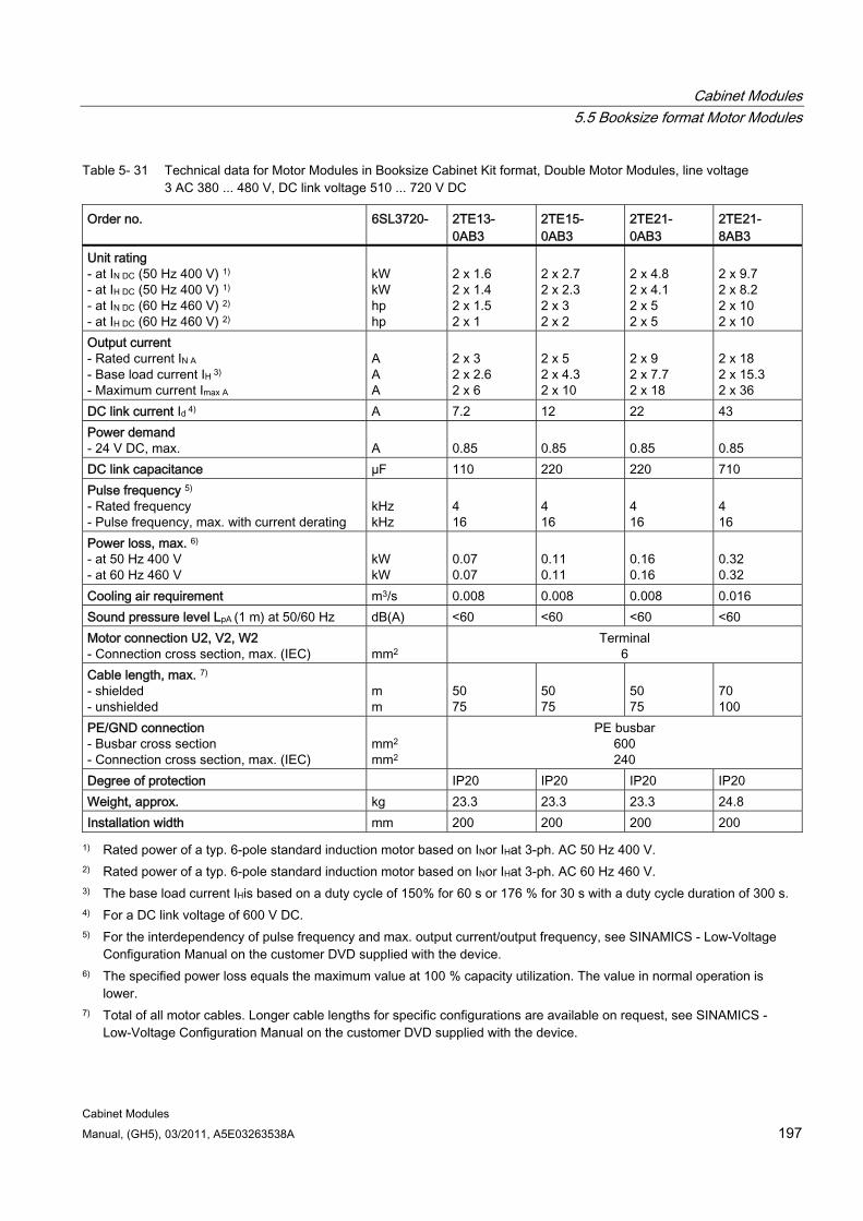
Cabinet Modules 5.5 Booksize format Motor Modules
Cabinet Modules Manual, (GH5), 03/2011, A5E03263538A 197
Table 5- 31 Technical data for Motor Modules in Booksize Cabinet Kit format, Double Motor Modules, line voltage 3 AC 380 ... 480 V, DC link voltage 510 ... 720 V DC
Order no. 6SL3720- 2TE13- 0AB3
2TE15- 0AB3
2TE21- 0AB3
2TE21- 8AB3
Unit rating - at IN DC (50 Hz 400 V) 1) - at IH DC (50 Hz 400 V) 1) - at IN DC (60 Hz 460 V) 2) - at IH DC (60 Hz 460 V) 2)
kW kW hp hp
2 x 1.6 2 x 1.4 2 x 1.5 2 x 1
2 x 2.7 2 x 2.3 2 x 3 2 x 2
2 x 4.8 2 x 4.1 2 x 5 2 x 5
2 x 9.7 2 x 8.2 2 x 10 2 x 10
Output current - Rated current IN A - Base load current IH 3) - Maximum current Imax A
A A A
2 x 3 2 x 2.6 2 x 6
2 x 5 2 x 4.3 2 x 10
2 x 9 2 x 7.7 2 x 18
2 x 18 2 x 15.3 2 x 36
DC link current Id 4) A 7.2 12 22 43 Power demand - 24 V DC, max.
A
0.85
0.85
0.85
0.85
DC link capacitance µF 110 220 220 710 Pulse frequency 5) - Rated frequency - Pulse frequency, max. with current derating
kHz kHz
4 16
4 16
4 16
4 16
Power loss, max. 6) - at 50 Hz 400 V - at 60 Hz 460 V
kW kW
0.07 0.07
0.11 0.11
0.16 0.16
0.32 0.32
Cooling air requirement m3/s 0.008 0.008 0.008 0.016 Sound pressure level LpA (1 m) at 50/60 Hz dB(A) <60 <60 <60 <60 Motor connection U2, V2, W2 - Connection cross section, max. (IEC)
mm2
Terminal 6
Cable length, max. 7) - shielded - unshielded
m m
50 75
50 75
50 75
70 100
PE/GND connection - Busbar cross section - Connection cross section, max. (IEC)
mm2
mm2
PE busbar 600 240
Degree of protection IP20 IP20 IP20 IP20 Weight, approx. kg 23.3 23.3 23.3 24.8 Installation width mm 200 200 200 200
1) Rated power of a typ. 6-pole standard induction motor based on INor IHat 3-ph. AC 50 Hz 400 V. 2) Rated power of a typ. 6-pole standard induction motor based on INor IHat 3-ph. AC 60 Hz 460 V. 3) The base load current IHis based on a duty cycle of 150% for 60 s or 176 % for 30 s with a duty cycle duration of 300 s. 4) For a DC link voltage of 600 V DC. 5) For the interdependency of pulse frequency and max. output current/output frequency, see SINAMICS - Low-Voltage
Configuration Manual on the customer DVD supplied with the device. 6) The specified power loss equals the maximum value at 100 % capacity utilization. The value in normal operation is
lower. 7) Total of all motor cables. Longer cable lengths for specific configurations are available on request, see SINAMICS -
Low-Voltage Configuration Manual on the customer DVD supplied with the device.
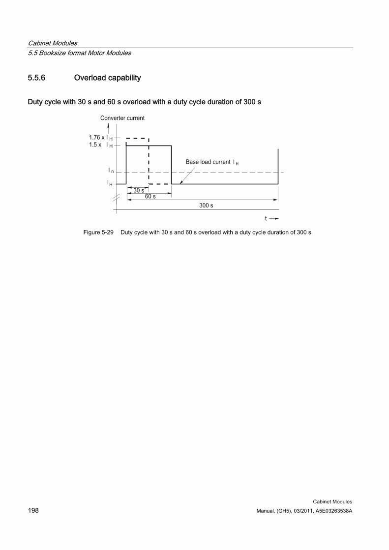
Cabinet Modules 5.5 Booksize format Motor Modules
Cabinet Modules 198 Manual, (GH5), 03/2011, A5E03263538A
5.5.6 Overload capability
Duty cycle with 30 s and 60 s overload with a duty cycle duration of 300 s
Figure 5-29 Duty cycle with 30 s and 60 s overload with a duty cycle duration of 300 s
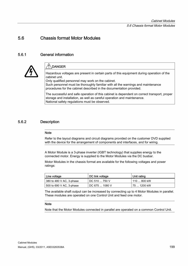
Cabinet Modules 5.6 Chassis format Motor Modules
Cabinet Modules Manual, (GH5), 03/2011, A5E03263538A 199
5.6 Chassis format Motor Modules
5.6.1 General information
DANGER
Hazardous voltages are present in certain parts of this equipment during operation of the cabinet unit. Only qualified personnel may work on the cabinet. Such personnel must be thoroughly familiar with all the warnings and maintenance procedures for the cabinet described in the documentation provided.
The successful and safe operation of this cabinet is dependent on correct transport, proper storage and installation, as well as careful operation and maintenance. National safety regulations must be observed.
5.6.2 Description
Note
Refer to the layout diagrams and circuit diagrams provided on the customer DVD supplied with the device for the arrangement of components and interfaces, and for wiring.
A Motor Module is a 3-phase inverter (IGBT technology) that supplies energy to the connected motor. Energy is supplied to the Motor Modules via the DC busbar.
Motor Modules in the chassis format are available for the following voltages and power ratings:
Line voltage DC link voltage Unit rating 380 to 480 V AC, 3-phase DC 510 ... 750 V 110 ... 800 kW 500 to 690 V AC, 3-phase DC 675 ... 1080 V 75 ... 1200 kW
The available shaft output can be increased by connecting up to 4 Motor Modules in parallel. These modules are operated on one Control Unit and feed one motor.
Note
Note that the Motor Modules connected in parallel are operated on a common Control Unit.
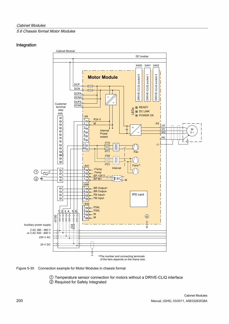
Cabinet Modules 5.6 Chassis format Motor Modules
Cabinet Modules 200 Manual, (GH5), 03/2011, A5E03263538A
Integration
=
=
Motor Module
Figure 5-30 Connection example for Motor Modules in chassis format
① Temperature sensor connection for motors without a DRIVE-CLiQ interface ② Required for Safety Integrated
Cabinet Modules 5.6 Chassis format Motor Modules
Cabinet Modules Manual, (GH5), 03/2011, A5E03263538A 201
Configuration Motor Modules contain the following components as standard:
Retaining device for the DC busbar, including the interface to the DC connections of the Motor Module (the necessary DC busbar must be provided separately as option M80 to M87).
Connection busbar for motor cables for Motor Modules with frame sizes FX and GX; for Motor Modules with frame sizes HX and JX, the motor cables are connected directly to the device.
Cable propping bar for the electric power cables
DRIVE-CLiQ interface (3 DRIVE-CLiQ sockets), without Control Unit
6-pole auxiliary voltage supply, including auxiliary power module and cables for looping through to the next Cabinet Module
PE busbar (60 x 10 mm), including jumper for looping through to the next Cabinet Module.
EMC-compliant design thanks to additional shielding measures and appropriate laying of cables.
Note
The configuration examples of the individual Motor Modules are used to illustrate the positioning of the factory-fitted components. They show the maximum possible configuration of the modules, which contain all options that can be ordered.
Refer to the layout diagrams (AO) on the customer DVD for the precise order-specific location of the components.

Cabinet Modules 5.6 Chassis format Motor Modules
Cabinet Modules 202 Manual, (GH5), 03/2011, A5E03263538A
X100
-F24
PE PE
-E 1
-T1
-F10
-F11
- T 10
-X9
-K10
-X2
-U 2-T 1
-V2-T 2
-W 2-T 3
-A10
-E240-X240H utschiene _ M oM o_ F
-X55 -B83
-K42
-K41
-X41
D /L -
C /L +
-Q 7
-F 1 -F 2-F 5
-R 7, -R 8
-
-T 30 .X21
Figure 5-31 Configuration of Motor Modules in chassis format (frame size FX)

Cabinet Modules 5.6 Chassis format Motor Modules
Cabinet Modules Manual, (GH5), 03/2011, A5E03263538A 203
-X10
0 -F24
PE
PE
- T 1
-E 2 -E3 -E4
-X 9
-T 10
-T 20
-K20
-F20
-F21
-K10
-F10
-F11
-X 2
-U 2 /-T1 -V 2/-T 2-W2 /-T3
-A10
-E24
0
-E24
1
-X24
0-X 55-B83
-K42
-K41
-X41
-T 30 .X 21
C /L +
D /L -
-Q7
-F 1 -F 3 -F 2 -F 4
-F5
-R 8
-R 7
Figure 5-32 Configuration of Motor Modules in chassis format (frame size JX)
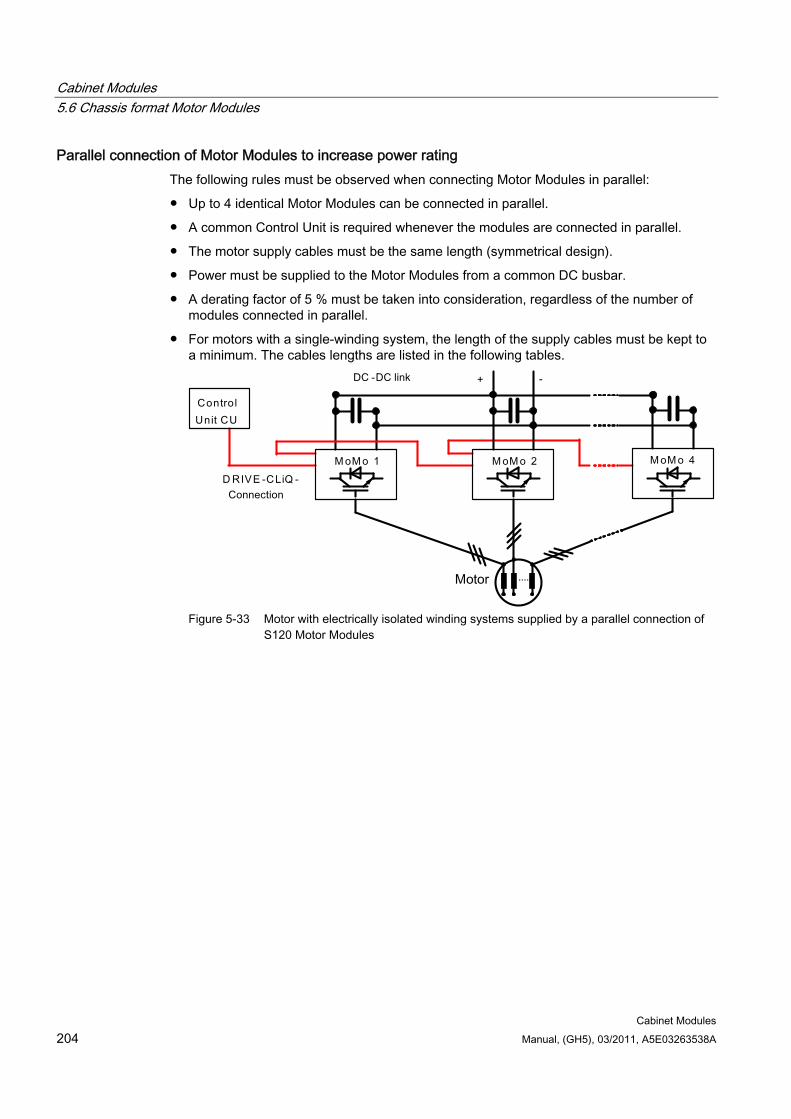
Cabinet Modules 5.6 Chassis format Motor Modules
Cabinet Modules 204 Manual, (GH5), 03/2011, A5E03263538A
Parallel connection of Motor Modules to increase power rating The following rules must be observed when connecting Motor Modules in parallel:
Up to 4 identical Motor Modules can be connected in parallel.
A common Control Unit is required whenever the modules are connected in parallel.
The motor supply cables must be the same length (symmetrical design).
Power must be supplied to the Motor Modules from a common DC busbar.
A derating factor of 5 % must be taken into consideration, regardless of the number of modules connected in parallel.
For motors with a single-winding system, the length of the supply cables must be kept to a minimum. The cables lengths are listed in the following tables.
Figure 5-33 Motor with electrically isolated winding systems supplied by a parallel connection of
S120 Motor Modules
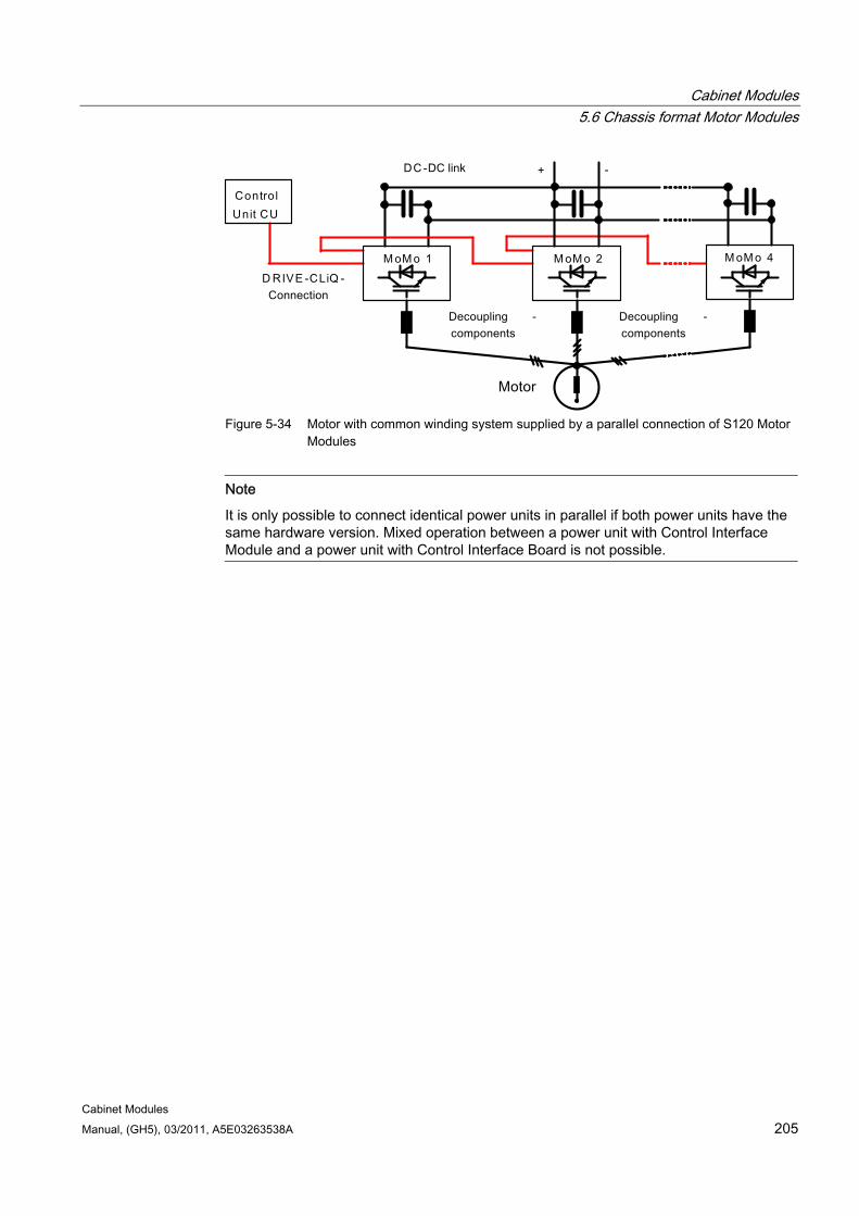
Cabinet Modules 5.6 Chassis format Motor Modules
Cabinet Modules Manual, (GH5), 03/2011, A5E03263538A 205
Figure 5-34 Motor with common winding system supplied by a parallel connection of S120 Motor
Modules
Note
It is only possible to connect identical power units in parallel if both power units have the same hardware version. Mixed operation between a power unit with Control Interface Module and a power unit with Control Interface Board is not possible.
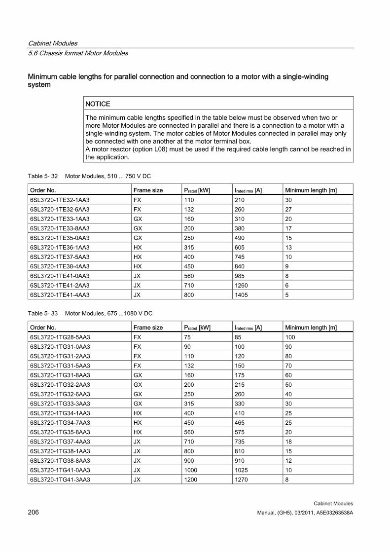
Cabinet Modules 5.6 Chassis format Motor Modules
Cabinet Modules 206 Manual, (GH5), 03/2011, A5E03263538A
Minimum cable lengths for parallel connection and connection to a motor with a single-winding system
NOTICE The minimum cable lengths specified in the table below must be observed when two or more Motor Modules are connected in parallel and there is a connection to a motor with a single-winding system. The motor cables of Motor Modules connected in parallel may only be connected with one another at the motor terminal box. A motor reactor (option L08) must be used if the required cable length cannot be reached in the application.
Table 5- 32 Motor Modules, 510 ... 750 V DC
Order No. Frame size Prated [kW] Irated rms [A] Minimum length [m] 6SL3720-1TE32-1AA3 FX 110 210 30 6SL3720-1TE32-6AA3 FX 132 260 27 6SL3720-1TE33-1AA3 GX 160 310 20 6SL3720-1TE33-8AA3 GX 200 380 17 6SL3720-1TE35-0AA3 GX 250 490 15 6SL3720-1TE36-1AA3 HX 315 605 13 6SL3720-1TE37-5AA3 HX 400 745 10 6SL3720-1TE38-4AA3 HX 450 840 9 6SL3720-1TE41-0AA3 JX 560 985 8 6SL3720-1TE41-2AA3 JX 710 1260 6 6SL3720-1TE41-4AA3 JX 800 1405 5
Table 5- 33 Motor Modules, 675 ...1080 V DC
Order No. Frame size Prated [kW] Irated rms [A] Minimum length [m] 6SL3720-1TG28-5AA3 FX 75 85 100 6SL3720-1TG31-0AA3 FX 90 100 90 6SL3720-1TG31-2AA3 FX 110 120 80 6SL3720-1TG31-5AA3 FX 132 150 70 6SL3720-1TG31-8AA3 GX 160 175 60 6SL3720-1TG32-2AA3 GX 200 215 50 6SL3720-1TG32-6AA3 GX 250 260 40 6SL3720-1TG33-3AA3 GX 315 330 30 6SL3720-1TG34-1AA3 HX 400 410 25 6SL3720-1TG34-7AA3 HX 450 465 25 6SL3720-1TG35-8AA3 HX 560 575 20 6SL3720-1TG37-4AA3 JX 710 735 18 6SL3720-1TG38-1AA3 JX 800 810 15 6SL3720-1TG38-8AA3 JX 900 910 12 6SL3720-1TG41-0AA3 JX 1000 1025 10 6SL3720-1TG41-3AA3 JX 1200 1270 8
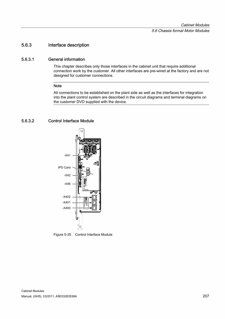
Cabinet Modules 5.6 Chassis format Motor Modules
Cabinet Modules Manual, (GH5), 03/2011, A5E03263538A 207
5.6.3 Interface description
5.6.3.1 General information This chapter describes only those interfaces in the cabinet unit that require additional connection work by the customer. All other interfaces are pre-wired at the factory and are not designed for customer connections.
Note
All connections to be established on the plant side as well as the interfaces for integration into the plant control system are described in the circuit diagrams and terminal diagrams on the customer DVD supplied with the device.
5.6.3.2 Control Interface Module
Figure 5-35 Control Interface Module
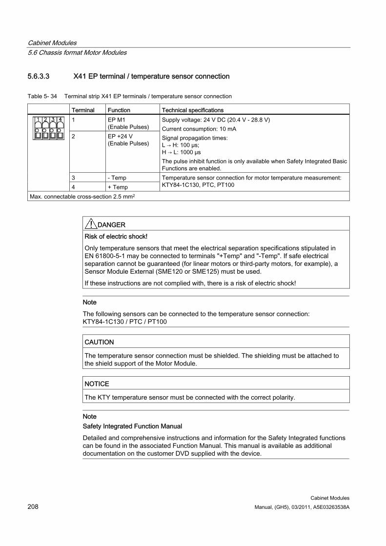
Cabinet Modules 5.6 Chassis format Motor Modules
Cabinet Modules 208 Manual, (GH5), 03/2011, A5E03263538A
5.6.3.3 X41 EP terminal / temperature sensor connection
Table 5- 34 Terminal strip X41 EP terminals / temperature sensor connection
Terminal Function Technical specifications 1 EP M1
(Enable Pulses) 2 EP +24 V
(Enable Pulses)
Supply voltage: 24 V DC (20.4 V - 28.8 V) Current consumption: 10 mA Signal propagation times: L → H: 100 μs; H → L: 1000 μs The pulse inhibit function is only available when Safety Integrated Basic Functions are enabled.
3 - Temp
4 + Temp Temperature sensor connection for motor temperature measurement: KTY84-1C130, PTC, PT100
Max. connectable cross-section 2.5 mm2
DANGER Risk of electric shock!
Only temperature sensors that meet the electrical separation specifications stipulated in EN 61800-5-1 may be connected to terminals "+Temp" and "-Temp". If safe electrical separation cannot be guaranteed (for linear motors or third-party motors, for example), a Sensor Module External (SME120 or SME125) must be used.
If these instructions are not complied with, there is a risk of electric shock!
Note
The following sensors can be connected to the temperature sensor connection: KTY84-1C130 / PTC / PT100
CAUTION The temperature sensor connection must be shielded. The shielding must be attached to the shield support of the Motor Module.
NOTICE The KTY temperature sensor must be connected with the correct polarity.
Note Safety Integrated Function Manual
Detailed and comprehensive instructions and information for the Safety Integrated functions can be found in the associated Function Manual. This manual is available as additional documentation on the customer DVD supplied with the device.
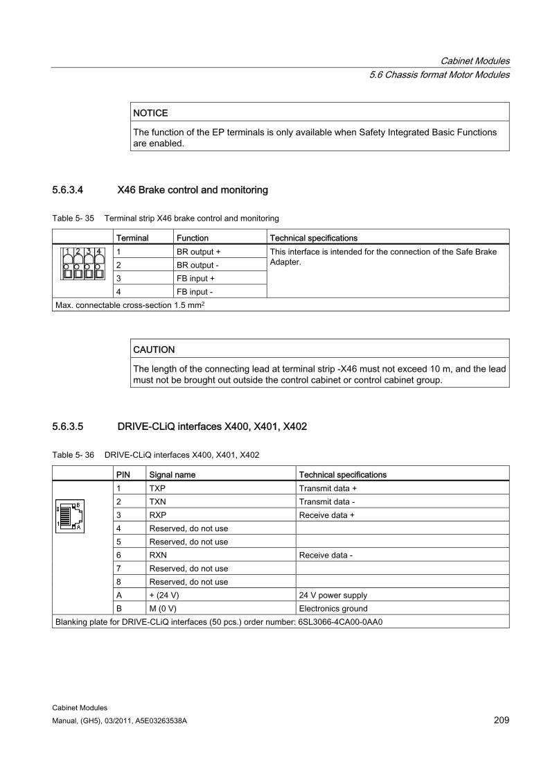
Cabinet Modules 5.6 Chassis format Motor Modules
Cabinet Modules Manual, (GH5), 03/2011, A5E03263538A 209
NOTICE The function of the EP terminals is only available when Safety Integrated Basic Functions are enabled.
5.6.3.4 X46 Brake control and monitoring
Table 5- 35 Terminal strip X46 brake control and monitoring
Terminal Function Technical specifications 1 BR output + 2 BR output - 3 FB input + 4 FB input -
This interface is intended for the connection of the Safe Brake Adapter.
Max. connectable cross-section 1.5 mm2
CAUTION The length of the connecting lead at terminal strip -X46 must not exceed 10 m, and the lead must not be brought out outside the control cabinet or control cabinet group.
5.6.3.5 DRIVE-CLiQ interfaces X400, X401, X402
Table 5- 36 DRIVE-CLiQ interfaces X400, X401, X402
PIN Signal name Technical specifications 1 TXP Transmit data + 2 TXN Transmit data - 3 RXP Receive data + 4 Reserved, do not use 5 Reserved, do not use 6 RXN Receive data - 7 Reserved, do not use 8 Reserved, do not use A + (24 V) 24 V power supply
B M (0 V) Electronics ground Blanking plate for DRIVE-CLiQ interfaces (50 pcs.) order number: 6SL3066-4CA00-0AA0
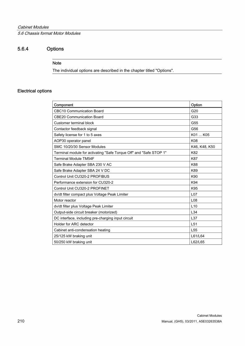
Cabinet Modules 5.6 Chassis format Motor Modules
Cabinet Modules 210 Manual, (GH5), 03/2011, A5E03263538A
5.6.4 Options
Note
The individual options are described in the chapter titled "Options".
Electrical options Component Option CBC10 Communication Board G20 CBE20 Communication Board G33 Customer terminal block G55 Contactor feedback signal G56 Safety license for 1 to 5 axes K01 ... K05 AOP30 operator panel K08 SMC 10/20/30 Sensor Modules K46, K48, K50 Terminal module for activating "Safe Torque Off" and "Safe STOP 1" K82 Terminal Module TM54F K87 Safe Brake Adapter SBA 230 V AC K88 Safe Brake Adapter SBA 24 V DC K89 Control Unit CU320-2 PROFIBUS K90 Performance extension for CU320-2 K94 Control Unit CU320-2 PROFINET K95 dv/dt filter compact plus Voltage Peak Limiter L07 Motor reactor L08 dv/dt filter plus Voltage Peak Limiter L10 Output-side circuit breaker (motorized) L34 DC interface, including pre-charging input circuit L37 Holder for ARC detector L51 Cabinet anti-condensation heating L55 25/125 kW braking unit L61/L64 50/250 kW braking unit L62/L65
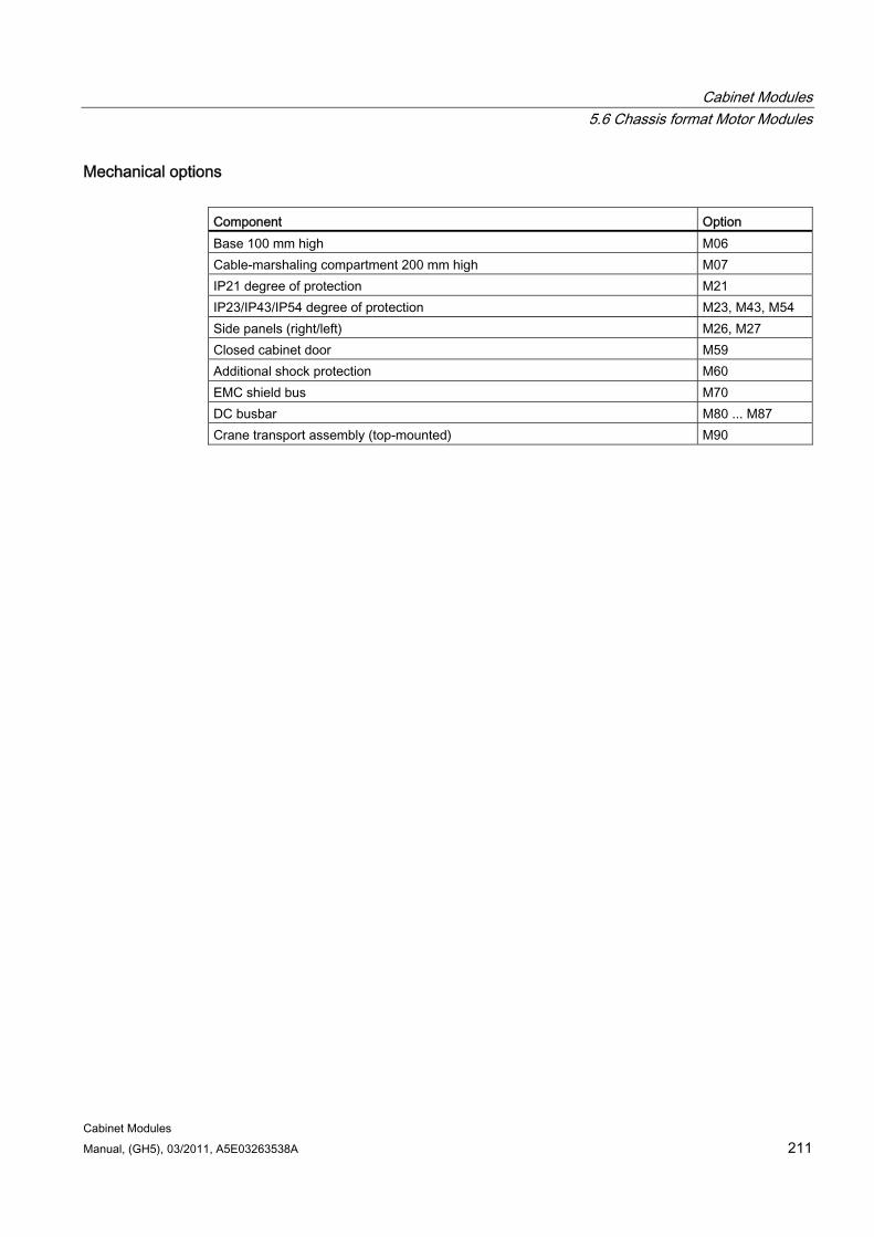
Cabinet Modules 5.6 Chassis format Motor Modules
Cabinet Modules Manual, (GH5), 03/2011, A5E03263538A 211
Mechanical options Component Option Base 100 mm high M06 Cable-marshaling compartment 200 mm high M07 IP21 degree of protection M21 IP23/IP43/IP54 degree of protection M23, M43, M54 Side panels (right/left) M26, M27 Closed cabinet door M59 Additional shock protection M60 EMC shield bus M70 DC busbar M80 ... M87 Crane transport assembly (top-mounted) M90
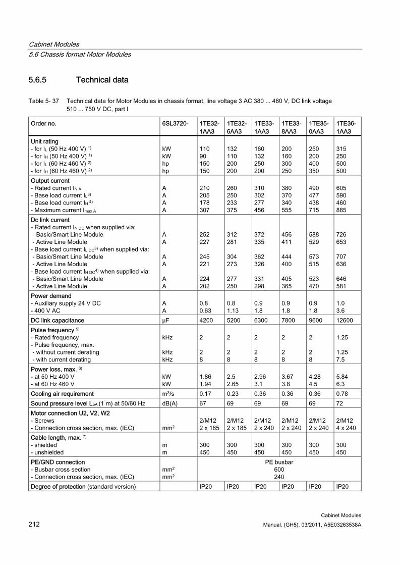
Cabinet Modules 5.6 Chassis format Motor Modules
Cabinet Modules 212 Manual, (GH5), 03/2011, A5E03263538A
5.6.5 Technical data
Table 5- 37 Technical data for Motor Modules in chassis format, line voltage 3 AC 380 ... 480 V, DC link voltage 510 ... 750 V DC, part I
Order no. 6SL3720- 1TE32-1AA3
1TE32-6AA3
1TE33-1AA3
1TE33- 8AA3
1TE35- 0AA3
1TE36-1AA3
Unit rating - for IL (50 Hz 400 V) 1) - for IH (50 Hz 400 V) 1) - for IL (60 Hz 460 V) 2) - for IH (60 Hz 460 V) 2)
kW kW hp hp
110 90 150 150
132 110 200 200
160 132 250 200
200 160 300 250
250 200 400 350
315 250 500 500
Output current - Rated current IN A - Base load current IL3)
- Base load current IH 4) - Maximum current Imax A
A A A A
210 205 178 307
260 250 233 375
310 302 277 456
380 370 340 555
490 477 438 715
605 590 460 885
Dc link current - Rated current IN DC when supplied via: - Basic/Smart Line Module - Active Line Module - Base load current IL DC3) when supplied via: - Basic/Smart Line Module - Active Line Module - Base load current IH DC4) when supplied via: - Basic/Smart Line Module - Active Line Module
A A A A A A
252 227 245 221 224 202
312 281 304 273 277 250
372 335 362 326 331 298
456 411 444 400 405 365
588 529 573 515 523 470
726 653 707 636 646 581
Power demand - Auxiliary supply 24 V DC - 400 V AC
A A
0.8 0.63
0.8 1.13
0.9 1.8
0.9 1.8
0.9 1.8
1.0 3.6
DC link capacitance µF 4200 5200 6300 7800 9600 12600 Pulse frequency 5) - Rated frequency - Pulse frequency, max. - without current derating - with current derating
kHz kHz kHz
2 2 8
2 2 8
2 2 8
2 2 8
2 2 8
1.25 1.25 7.5
Power loss, max. 6) - at 50 Hz 400 V - at 60 Hz 460 V
kW kW
1.86 1.94
2.5 2.65
2.96 3.1
3.67 3.8
4.28 4.5
5.84 6.3
Cooling air requirement m3/s 0.17 0.23 0.36 0.36 0.36 0.78 Sound pressure level LpA (1 m) at 50/60 Hz dB(A) 67 69 69 69 69 72 Motor connection U2, V2, W2 - Screws - Connection cross section, max. (IEC)
mm2
2/M12 2 x 185
2/M12 2 x 185
2/M12 2 x 240
2/M12 2 x 240
2/M12 2 x 240
2/M12 4 x 240
Cable length, max. 7) - shielded - unshielded
m m
300 450
300 450
300 450
300 450
300 450
300 450
PE/GND connection - Busbar cross section - Connection cross section, max. (IEC)
mm2
mm2
PE busbar 600 240
Degree of protection (standard version) IP20 IP20 IP20 IP20 IP20 IP20
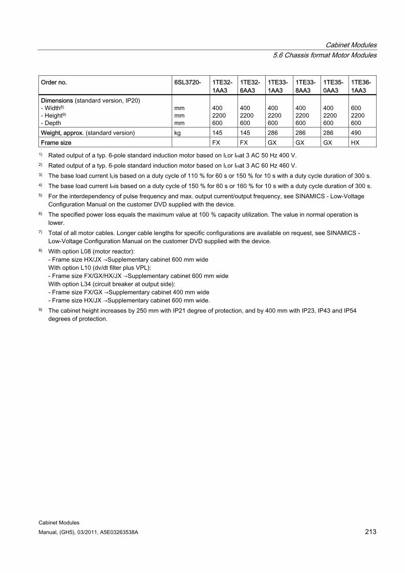
Cabinet Modules 5.6 Chassis format Motor Modules
Cabinet Modules Manual, (GH5), 03/2011, A5E03263538A 213
Order no. 6SL3720- 1TE32-1AA3
1TE32-6AA3
1TE33- 1AA3
1TE33- 8AA3
1TE35-0AA3
1TE36-1AA3
Dimensions (standard version, IP20) - Width8) - Height9) - Depth
mm mm mm
400 2200 600
400 2200 600
400 2200 600
400 2200 600
400 2200 600
600 2200 600
Weight, approx. (standard version) kg 145 145 286 286 286 490 Frame size FX FX GX GX GX HX
1) Rated output of a typ. 6-pole standard induction motor based on ILor IHat 3 AC 50 Hz 400 V. 2) Rated output of a typ. 6-pole standard induction motor based on ILor IHat 3 AC 60 Hz 460 V. 3) The base load current ILis based on a duty cycle of 110 % for 60 s or 150 % for 10 s with a duty cycle duration of 300 s. 4) The base load current IHis based on a duty cycle of 150 % for 60 s or 160 % for 10 s with a duty cycle duration of 300 s. 5) For the interdependency of pulse frequency and max. output current/output frequency, see SINAMICS - Low-Voltage
Configuration Manual on the customer DVD supplied with the device. 6) The specified power loss equals the maximum value at 100 % capacity utilization. The value in normal operation is
lower. 7) Total of all motor cables. Longer cable lengths for specific configurations are available on request, see SINAMICS -
Low-Voltage Configuration Manual on the customer DVD supplied with the device. 8) With option L08 (motor reactor):
- Frame size HX/JX →Supplementary cabinet 600 mm wide With option L10 (dv/dt filter plus VPL): - Frame size FX/GX/HX/JX →Supplementary cabinet 600 mm wide With option L34 (circuit breaker at output side): - Frame size FX/GX →Supplementary cabinet 400 mm wide - Frame size HX/JX →Supplementary cabinet 600 mm wide.
9) The cabinet height increases by 250 mm with IP21 degree of protection, and by 400 mm with IP23, IP43 and IP54 degrees of protection.
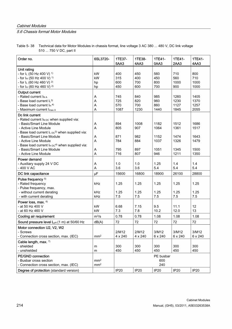
Cabinet Modules 5.6 Chassis format Motor Modules
Cabinet Modules 214 Manual, (GH5), 03/2011, A5E03263538A
Table 5- 38 Technical data for Motor Modules in chassis format, line voltage 3 AC 380 ... 480 V, DC link voltage 510 ... 750 V DC, part II
Order no. 6SL3720- 1TE37- 5AA3
1TE38- 4AA3
1TE41- 0AA3
1TE41- 2AA3
1TE41- 4AA3
Unit rating - for IL (50 Hz 400 V) 1) - for IH (50 Hz 400 V) 1) - for IL (60 Hz 460 V) 2) - for IH (60 Hz 460 V) 2)
kW kW hp hp
400 315 600 450
450 400 700 600
560 450 800 700
710 560 1000 900
800 710 1000 1000
Output current - Rated current IN A - Base load current IL3)
- Base load current IH 4) - Maximum current Imax A
A A A A
745 725 570 1087
840 820 700 1230
985 960 860 1440
1260 1230 1127 1845
1405 1370 1257 2055
Dc link current - Rated current IN DC when supplied via: - Basic/Smart Line Module - Active Line Module - Base load current IL DC3) when supplied via: - Basic/Smart Line Module - Active Line Module - Base load current IH DC4) when supplied via: - Basic/Smart Line Module - Active Line Module
A A A A A A
894 805 871 784 795 716
1008 907 982 884 897 807
1182 1064 1152 1037 1051 946
1512 1361 1474 1326 1345 1211
1686 1517 1643 1479 1500 1350
Power demand - Auxiliary supply 24 V DC - 400 V AC
A A
1.0 3.6
1.0 3.6
1.25 5.4
1.4 5.4
1.4 5.4
DC link capacitance µF 15600 16800 18900 26100 28800 Pulse frequency 5) - Rated frequency - Pulse frequency, max. - without current derating - with current derating
kHz kHz kHz
1.25 1.25 7.5
1.25 1.25 7.5
1.25 1.25 7.5
1.25 1.25 7.5
1.25 1.25 7.5
Power loss, max. 6) - at 50 Hz 400 V - at 60 Hz 460 V
kW kW
6.68 7.3
7.15 7.8
9.5 10.2
11.1 12.0
12 13
Cooling air requirement m3/s 0.78 0.78 1.08 1.08 1.08 Sound pressure level LpA (1 m) at 50/60 Hz dB(A) 72 72 72 72 72 Motor connection U2, V2, W2 - Screws - Connection cross section, max. (IEC)
mm2
2/M12 4 x 240
2/M12 4 x 240
3/M12 6 x 240
3/M12 6 x 240
3/M12 6 x 240
Cable length, max. 7) - shielded - unshielded
m m
300 450
300 450
300 450
300 450
300 450
PE/GND connection - Busbar cross section - Connection cross section, max. (IEC)
mm2
mm2
PE busbar 600 240
Degree of protection (standard version) IP20 IP20 IP20 IP20 IP20
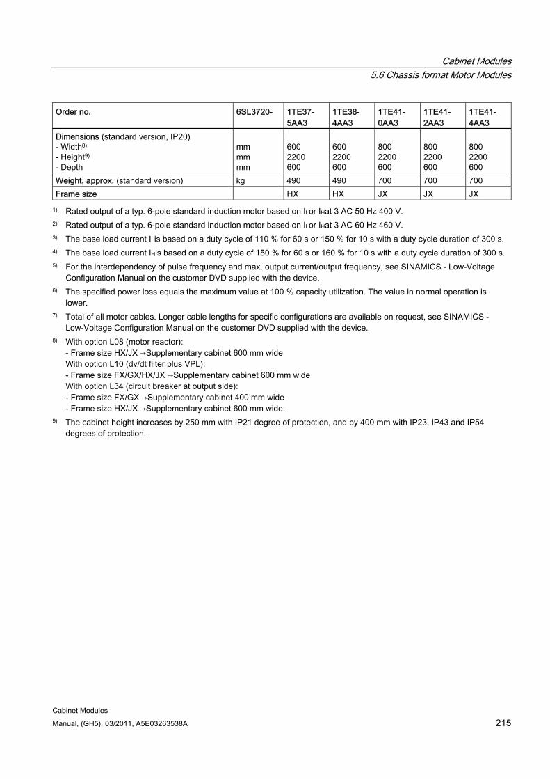
Cabinet Modules 5.6 Chassis format Motor Modules
Cabinet Modules Manual, (GH5), 03/2011, A5E03263538A 215
Order no. 6SL3720- 1TE37- 5AA3
1TE38- 4AA3
1TE41- 0AA3
1TE41- 2AA3
1TE41- 4AA3
Dimensions (standard version, IP20) - Width8) - Height9) - Depth
mm mm mm
600 2200 600
600 2200 600
800 2200 600
800 2200 600
800 2200 600
Weight, approx. (standard version) kg 490 490 700 700 700 Frame size HX HX JX JX JX
1) Rated output of a typ. 6-pole standard induction motor based on ILor IHat 3 AC 50 Hz 400 V. 2) Rated output of a typ. 6-pole standard induction motor based on ILor IHat 3 AC 60 Hz 460 V. 3) The base load current ILis based on a duty cycle of 110 % for 60 s or 150 % for 10 s with a duty cycle duration of 300 s. 4) The base load current IHis based on a duty cycle of 150 % for 60 s or 160 % for 10 s with a duty cycle duration of 300 s. 5) For the interdependency of pulse frequency and max. output current/output frequency, see SINAMICS - Low-Voltage
Configuration Manual on the customer DVD supplied with the device. 6) The specified power loss equals the maximum value at 100 % capacity utilization. The value in normal operation is
lower. 7) Total of all motor cables. Longer cable lengths for specific configurations are available on request, see SINAMICS -
Low-Voltage Configuration Manual on the customer DVD supplied with the device. 8) With option L08 (motor reactor):
- Frame size HX/JX →Supplementary cabinet 600 mm wide With option L10 (dv/dt filter plus VPL): - Frame size FX/GX/HX/JX →Supplementary cabinet 600 mm wide With option L34 (circuit breaker at output side): - Frame size FX/GX →Supplementary cabinet 400 mm wide - Frame size HX/JX →Supplementary cabinet 600 mm wide.
9) The cabinet height increases by 250 mm with IP21 degree of protection, and by 400 mm with IP23, IP43 and IP54 degrees of protection.
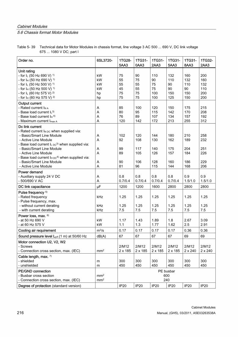
Cabinet Modules 5.6 Chassis format Motor Modules
Cabinet Modules 216 Manual, (GH5), 03/2011, A5E03263538A
Table 5- 39 Technical data for Motor Modules in chassis format, line voltage 3 AC 500 ... 690 V, DC link voltage 675 ... 1080 V DC; part I
Order no. 6SL3720- 1TG28-5AA3
1TG31-0AA3
1TG31-2AA3
1TG31- 5AA3
1TG31- 8AA3
1TG32-2AA3
Unit rating - for IL (50 Hz 690 V) 1) - for IH (50 Hz 690 V) 1)
- for IL (50 Hz 500 V) 1) - for IH (50 Hz 500 V) 1) - for IL (60 Hz 575 V) 2) - for IH (60 Hz 575 V) 2)
kW kW kW kW hp hp
75 55 55 45 75 75
90 75 55 55 75 75
110 90 75 75 100 100
132 110 90 90 150 125
160 132 110 90 150 150
200 160 132 110 200 200
Output current - Rated current IN A - Base load current IL3)
- Base load current IH 4) - Maximum current Imax A
A A A A
85 80 76 120
100 95 89 142
120 115 107 172
150 142 134 213
175 170 157 255
215 208 192 312
Dc link current - Rated current IN DC when supplied via: - Basic/Smart Line Module - Active Line Module - Base load current IL DC3) when supplied via: - Basic/Smart Line Module - Active Line Module - Base load current IH DC4) when supplied via: - Basic/Smart Line Module - Active Line Module
A A A A A A
102 92 99 89 90 81
120 108 117 105 106 96
144 130 140 126 128 115
180 162 175 157 160 144
210 189 204 184 186 168
258 232 251 226 229 206
Power demand - Auxiliary supply 24 V DC - 500/690 V AC
A A
0.8 0.7/0.4
0.8 0.7/0.4
0.8 0.7/0.4
0.8 0.7/0.4
0.9 1.5/1.0
0.9 1.5/1.0
DC link capacitance µF 1200 1200 1600 2800 2800 2800 Pulse frequency 5) - Rated frequency - Pulse frequency, max. - without current derating - with current derating
kHz kHz kHz
1.25 1.25 7.5
1.25 1.25 7.5
1.25 1.25 7.5
1.25 1.25 7.5
1.25 1.25 7.5
1.25 1.25 7.5
Power loss, max. 6) - at 50 Hz 690 V - at 60 Hz 575 V
kW kW
1.17 1.1
1.43 1.3
1.89 1.77
1.8 1.62
2.67 2.5
3.09 2.91
Cooling air requirement m3/s 0.17 0.17 0.17 0.17 0.36 0.36 Sound pressure level LpA (1 m) at 50/60 Hz dB(A) 67 67 67 67 69 69 Motor connection U2, V2, W2 - Screws - Connection cross section, max. (IEC)
mm2
2/M12 2 x 185
2/M12 2 x 185
2/M12 2 x 185
2/M12 2 x 185
2/M12 2 x 240
2/M12 2 x 240
Cable length, max. 7) - shielded - unshielded
m m
300 450
300 450
300 450
300 450
300 450
300 450
PE/GND connection - Busbar cross section - Connection cross section, max. (IEC)
mm2
mm2
PE busbar 600 240
Degree of protection (standard version) IP20 IP20 IP20 IP20 IP20 IP20
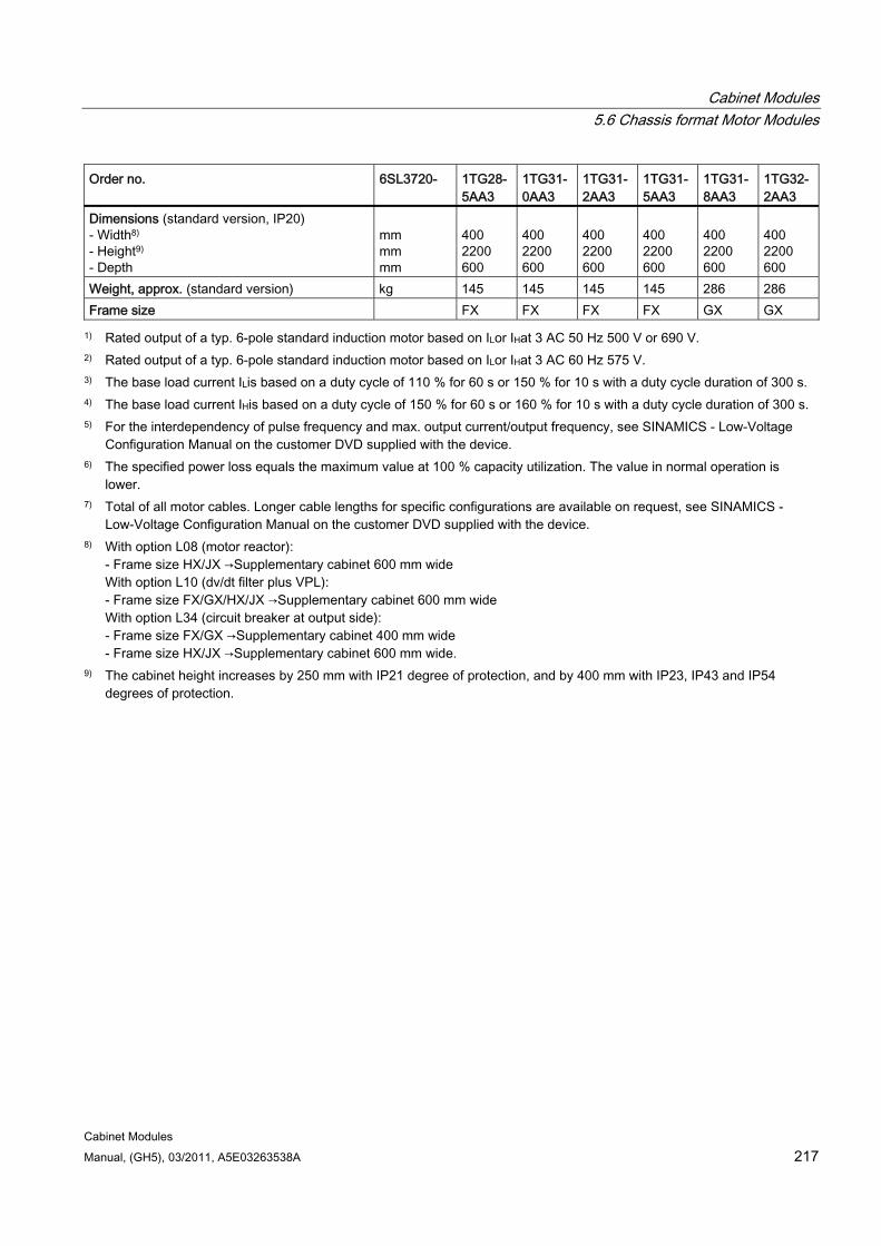
Cabinet Modules 5.6 Chassis format Motor Modules
Cabinet Modules Manual, (GH5), 03/2011, A5E03263538A 217
Order no. 6SL3720- 1TG28-5AA3
1TG31-0AA3
1TG31- 2AA3
1TG31- 5AA3
1TG31-8AA3
1TG32-2AA3
Dimensions (standard version, IP20) - Width8) - Height9) - Depth
mm mm mm
400 2200 600
400 2200 600
400 2200 600
400 2200 600
400 2200 600
400 2200 600
Weight, approx. (standard version) kg 145 145 145 145 286 286 Frame size FX FX FX FX GX GX
1) Rated output of a typ. 6-pole standard induction motor based on ILor IHat 3 AC 50 Hz 500 V or 690 V. 2) Rated output of a typ. 6-pole standard induction motor based on ILor IHat 3 AC 60 Hz 575 V. 3) The base load current ILis based on a duty cycle of 110 % for 60 s or 150 % for 10 s with a duty cycle duration of 300 s. 4) The base load current IHis based on a duty cycle of 150 % for 60 s or 160 % for 10 s with a duty cycle duration of 300 s. 5) For the interdependency of pulse frequency and max. output current/output frequency, see SINAMICS - Low-Voltage
Configuration Manual on the customer DVD supplied with the device. 6) The specified power loss equals the maximum value at 100 % capacity utilization. The value in normal operation is
lower. 7) Total of all motor cables. Longer cable lengths for specific configurations are available on request, see SINAMICS -
Low-Voltage Configuration Manual on the customer DVD supplied with the device. 8) With option L08 (motor reactor):
- Frame size HX/JX →Supplementary cabinet 600 mm wide With option L10 (dv/dt filter plus VPL): - Frame size FX/GX/HX/JX →Supplementary cabinet 600 mm wide With option L34 (circuit breaker at output side): - Frame size FX/GX →Supplementary cabinet 400 mm wide - Frame size HX/JX →Supplementary cabinet 600 mm wide.
9) The cabinet height increases by 250 mm with IP21 degree of protection, and by 400 mm with IP23, IP43 and IP54 degrees of protection.
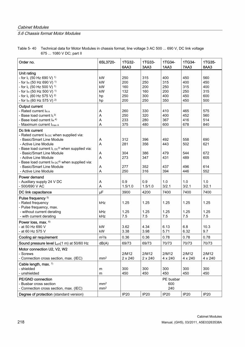
Cabinet Modules 5.6 Chassis format Motor Modules
Cabinet Modules 218 Manual, (GH5), 03/2011, A5E03263538A
Table 5- 40 Technical data for Motor Modules in chassis format, line voltage 3 AC 500 ... 690 V, DC link voltage 675 ... 1080 V DC; part II
Order no. 6SL3720- 1TG32- 6AA3
1TG33- 3AA3
1TG34- 1AA3
1TG34- 7AA3
1TG35- 8AA3
Unit rating - for IL (50 Hz 690 V) 1) - for IH (50 Hz 690 V) 1)
- for IL (50 Hz 500 V) 1) - for IH (50 Hz 500 V) 1) - for IL (60 Hz 575 V) 2) - for IH (60 Hz 575 V) 2)
kW kW kW kW hp hp
250 200 160 132 250 200
315 250 200 160 300 250
400 315 250 200 400 350
450 400 315 250 450 450
560 450 400 315 600 500
Output current - Rated current IN A - Base load current IL3)
- Base load current IH 4) - Maximum current Imax A
A A A A
260 250 233 375
330 320 280 480
410 400 367 600
465 452 416 678
575 560 514 840
Dc link current - Rated current IN DC when supplied via: - Basic/Smart Line Module - Active Line Module - Base load current IL DC3) when supplied via: - Basic/Smart Line Module - Active Line Module - Base load current IH DC4) when supplied via: - Basic/Smart Line Module - Active Line Module
A A A A A A
312 281 304 273 277 250
396 356 386 347 352 316
492 443 479 431 437 394
558 502 544 489 496 446
690 621 672 605 614 552
Power demand - Auxiliary supply 24 V DC - 500/690 V AC
A A
0.9 1.5/1.0
0.9 1.5/1.0
1.0 3/2.1
1.0 3/2.1
1.0 3/2.1
DC link capacitance µF 3900 4200 7400 7400 7400 Pulse frequency 5) - Rated frequency - Pulse frequency, max. - without current derating - with current derating
kHz kHz kHz
1.25 1.25 7.5
1.25 1.25 7.5
1.25 1.25 7.5
1.25 1.25 7.5
1.25 1.25 7.5
Power loss, max. 6) - at 50 Hz 690 V - at 60 Hz 575 V
kW kW
3.62 3.38
4.34 3.98
6.13 5.71
6.8 6.32
10.3 9.7
Cooling air requirement m3/s 0.36 0.36 0.78 0.78 0.78 Sound pressure level LpA(1 m) at 50/60 Hz dB(A) 69/73 69/73 70/73 70/73 70/73 Motor connection U2, V2, W2 - Screws - Connection cross section, max. (IEC)
mm2
2/M12 2 x 240
2/M12 2 x 240
2/M12 4 x 240
2/M12 4 x 240
2/M12 4 x 240
Cable length, max. 7) - shielded - unshielded
m m
300 450
300 450
300 450
300 450
300 450
PE/GND connection - Busbar cross section - Connection cross section, max. (IEC)
mm2
mm2
PE busbar 600 240
Degree of protection (standard version) IP20 IP20 IP20 IP20 IP20
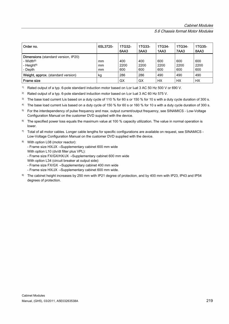
Cabinet Modules 5.6 Chassis format Motor Modules
Cabinet Modules Manual, (GH5), 03/2011, A5E03263538A 219
Order no. 6SL3720- 1TG32- 6AA3
1TG33- 3AA3
1TG34- 1AA3
1TG34- 7AA3
1TG35- 8AA3
Dimensions (standard version, IP20) - Width8) - Height9) - Depth
mm mm mm
400 2200 600
400 2200 600
600 2200 600
600 2200 600
600 2200 600
Weight, approx. (standard version) kg 286 286 490 490 490 Frame size GX GX HX HX HX
1) Rated output of a typ. 6-pole standard induction motor based on ILor IHat 3 AC 50 Hz 500 V or 690 V. 2) Rated output of a typ. 6-pole standard induction motor based on ILor IHat 3 AC 60 Hz 575 V. 3) The base load current ILis based on a duty cycle of 110 % for 60 s or 150 % for 10 s with a duty cycle duration of 300 s. 4) The base load current IHis based on a duty cycle of 150 % for 60 s or 160 % for 10 s with a duty cycle duration of 300 s. 5) For the interdependency of pulse frequency and max. output current/output frequency, see SINAMICS - Low-Voltage
Configuration Manual on the customer DVD supplied with the device. 6) The specified power loss equals the maximum value at 100 % capacity utilization. The value in normal operation is
lower. 7) Total of all motor cables. Longer cable lengths for specific configurations are available on request, see SINAMICS -
Low-Voltage Configuration Manual on the customer DVD supplied with the device. 8) With option L08 (motor reactor):
- Frame size HX/JX →Supplementary cabinet 600 mm wide With option L10 (dv/dt filter plus VPL): - Frame size FX/GX/HX/JX →Supplementary cabinet 600 mm wide With option L34 (circuit breaker at output side): - Frame size FX/GX →Supplementary cabinet 400 mm wide - Frame size HX/JX →Supplementary cabinet 600 mm wide.
9) The cabinet height increases by 250 mm with IP21 degree of protection, and by 400 mm with IP23, IP43 and IP54 degrees of protection.
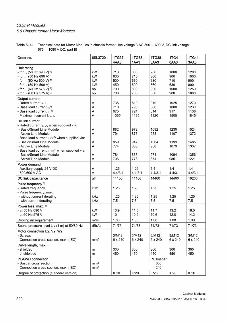
Cabinet Modules 5.6 Chassis format Motor Modules
Cabinet Modules 220 Manual, (GH5), 03/2011, A5E03263538A
Table 5- 41 Technical data for Motor Modules in chassis format, line voltage 3 AC 500 ... 690 V, DC link voltage 675 ... 1080 V DC; part III
Order no. 6SL3720- 1TG37- 4AA3
1TG38- 1AA3
1TG38- 8AA3
1TG41- 0AA3
1TG41- 3AA3
Unit rating - for IL (50 Hz 690 V) 1) - for IH (50 Hz 690 V) 1)
- for IL (50 Hz 500 V) 1) - for IH (50 Hz 500 V) 1) - for IL (60 Hz 575 V) 2) - for IH (60 Hz 575 V) 2)
kW kW kW kW hp hp
710 630 500 450 700 700
800 710 560 500 800 700
900 800 630 560 900 800
1000 900 710 630 1000 900
1200 1000 900 800 1250 1000
Output current - Rated current IN A - Base load current IL3)
- Base load current IH 4) - Maximum current Imax A
A A A A
735 710 675 1065
810 790 724 1185
910 880 814 1320
1025 1000 917 1500
1270 1230 1136 1845
Dc link current - Rated current IN DC when supplied via: - Basic/Smart Line Module - Active Line Module - Base load current IL DC3) when supplied via: - Basic/Smart Line Module - Active Line Module - Base load current IH DC4) when supplied via: - Basic/Smart Line Module - Active Line Module
A A A A A A
882 794 859 774 784 706
972 875 947 853 865 778
1092 983 1064 958 971 874
1230 1107 1199 1079 1094 985
1524 1372 1485 1337 1356 1221
Power demand - Auxiliary supply 24 V DC - 500/690 V AC
A A
1.25 4.4/3.1
1.25 4.4/3.1
1.4 4.4/3.1
1.4 4.4/3.1
1.4 4.4/3.1
DC link capacitance µF 11100 11100 14400 14400 19200 Pulse frequency 5) - Rated frequency - Pulse frequency, max. - without current derating - with current derating
kHz kHz kHz
1.25 1.25 7.5
1.25 1.25 7.5
1.25 1.25 7.5
1.25 1.25 7.5
1.25 1.25 7.5
Power loss, max. 6) - at 50 Hz 690 V - at 60 Hz 575 V
kW kW
10.9 10
11.5 10.5
11.7 10.6
13.2 12.0
16.0 14.2
Cooling air requirement m3/s 1.08 1.08 1.08 1.08 1.08 Sound pressure level LpA (1 m) at 50/60 Hz dB(A) 71/73 71/73 71/73 71/73 71/73 Motor connection U2, V2, W2 - Screws - Connection cross section, max. (IEC)
mm2
3/M12 6 x 240
3/M12 6 x 240
3/M12 6 x 240
3/M12 6 x 240
3/M12 6 x 240
Cable length, max. 7) - shielded - unshielded
m m
300 450
300 450
300 450
300 450
300 450
PE/GND connection - Busbar cross section - Connection cross section, max. (IEC)
mm2
mm2
PE busbar 600 240
Degree of protection (standard version) IP20 IP20 IP20 IP20 IP20
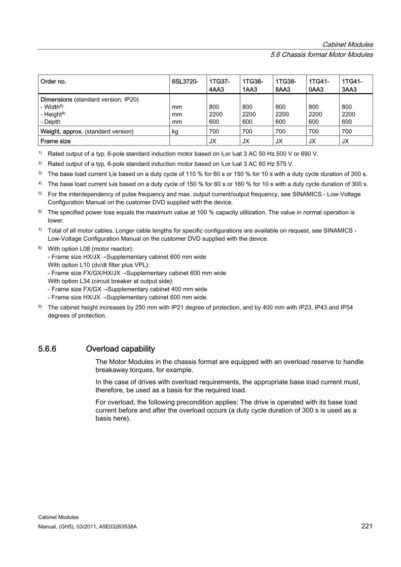
Cabinet Modules 5.6 Chassis format Motor Modules
Cabinet Modules Manual, (GH5), 03/2011, A5E03263538A 221
Order no. 6SL3720- 1TG37- 4AA3
1TG38- 1AA3
1TG38- 8AA3
1TG41- 0AA3
1TG41- 3AA3
Dimensions (standard version, IP20) - Width8) - Height9) - Depth
mm mm mm
800 2200 600
800 2200 600
800 2200 600
800 2200 600
800 2200 600
Weight, approx. (standard version) kg 700 700 700 700 700 Frame size JX JX JX JX JX
1) Rated output of a typ. 6-pole standard induction motor based on ILor IHat 3 AC 50 Hz 500 V or 690 V. 2) Rated output of a typ. 6-pole standard induction motor based on ILor IHat 3 AC 60 Hz 575 V. 3) The base load current ILis based on a duty cycle of 110 % for 60 s or 150 % for 10 s with a duty cycle duration of 300 s. 4) The base load current IHis based on a duty cycle of 150 % for 60 s or 160 % for 10 s with a duty cycle duration of 300 s. 5) For the interdependency of pulse frequency and max. output current/output frequency, see SINAMICS - Low-Voltage
Configuration Manual on the customer DVD supplied with the device. 6) The specified power loss equals the maximum value at 100 % capacity utilization. The value in normal operation is
lower. 7) Total of all motor cables. Longer cable lengths for specific configurations are available on request, see SINAMICS -
Low-Voltage Configuration Manual on the customer DVD supplied with the device. 8) With option L08 (motor reactor):
- Frame size HX/JX →Supplementary cabinet 600 mm wide With option L10 (dv/dt filter plus VPL): - Frame size FX/GX/HX/JX →Supplementary cabinet 600 mm wide With option L34 (circuit breaker at output side): - Frame size FX/GX →Supplementary cabinet 400 mm wide - Frame size HX/JX →Supplementary cabinet 600 mm wide.
9) The cabinet height increases by 250 mm with IP21 degree of protection, and by 400 mm with IP23, IP43 and IP54 degrees of protection.
5.6.6 Overload capability The Motor Modules in the chassis format are equipped with an overload reserve to handle breakaway torques, for example.
In the case of drives with overload requirements, the appropriate base load current must, therefore, be used as a basis for the required load.
For overload, the following precondition applies: The drive is operated with its base load current before and after the overload occurs (a duty cycle duration of 300 s is used as a basis here).
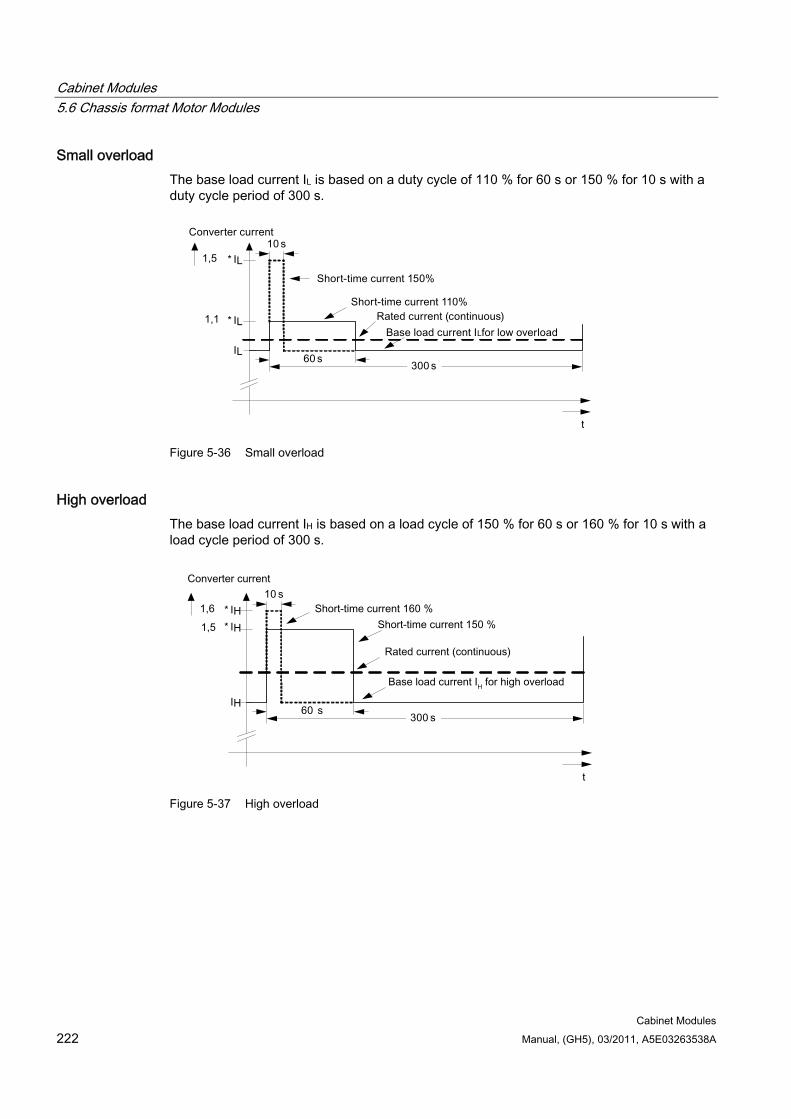
Cabinet Modules 5.6 Chassis format Motor Modules
Cabinet Modules 222 Manual, (GH5), 03/2011, A5E03263538A
Small overload The base load current IL is based on a duty cycle of 110 % for 60 s or 150 % for 10 s with a duty cycle period of 300 s.
Figure 5-36 Small overload
High overload The base load current IH is based on a load cycle of 150 % for 60 s or 160 % for 10 s with a load cycle period of 300 s.
Figure 5-37 High overload
Cabinet Modules 5.7 Central Braking Modules
Cabinet Modules Manual, (GH5), 03/2011, A5E03263538A 223
5.7 Central Braking Modules
5.7.1 General information
DANGER
Hazardous voltages are present in certain parts of this equipment during operation of the cabinet unit. Only qualified personnel may work on the cabinet. Such personnel must be thoroughly familiar with all the warnings and maintenance procedures for the cabinet described in the documentation provided.
The successful and safe operation of this cabinet is dependent on correct transport, proper storage and installation, as well as careful operation and maintenance. National safety regulations must be observed.
5.7.2 Description
Note
Refer to the layout diagrams and circuit diagrams provided on the enclosed customer DVD for the arrangement of components and interfaces, and for wiring.
Central Braking Modules limit the DC link voltage at a central location in the drive line-up when the motors are operated in regenerative mode and energy recovery to the supply system is not possible. If, in regenerative mode, the voltage of the DC busbar exceeds a limit value, an externally installed braking resistor is switched in, thus restricting the voltage from increasing further. The regenerative energy is converted to heat loss. The braking resistor is switched in by the Braking Module inside the Cabinet Module.
Central Braking Modules are an alternative to the optional Braking Modules (option L61/L62 or L64/L65) and are particularly suitable when high braking power is required in a drive line-up.
Central Braking Modules operate as fully stand-alone modules. They only require a connection to the DC link. An external control voltage is not required.
The capacitor module in the Central Braking Module is an extension of the DC link capacitance for the safe functioning of the Braking Module.
The built-in fan means that Central Braking Modules are also suitable for high continuous power systems.
Cabinet Modules 5.7 Central Braking Modules
Cabinet Modules 224 Manual, (GH5), 03/2011, A5E03263538A
Braking resistors corresponding to the rated powers are available for the Central Braking Modules. Braking resistors which are suitable for other applications are available on request.
WARNING The fan is switched on and off by means of a temperature control, which prevents it from running unnecessarily.
The fan can start up on its own.
WARNING The Braking Module incorporated into the Central Braking Module is able to support a higher braking power than standard braking resistors.
The braking resistor is only designed for occasional regenerative operation in accordance with the specified duty cycles.
If the braking resistor does not meet your particular requirements, an appropriate braking resistor must be requested on an order-specific basis.
Central Braking Modules are available for the following voltages and power ratings:
Line voltage Rated power 380 to 480 V AC, 3-phase 500 / 1000 kW 500 to 600 V AC, 3-phase 550 / 1100 kW 660 to 690 V AC, 3-phase 630 / 1200 kW
The braking power can be increased by connecting Central Braking Modules in parallel, refer to Point "Parallel connection of Central Braking Modules" at the end of this section.
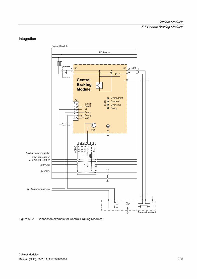
Cabinet Modules 5.7 Central Braking Modules
Cabinet Modules Manual, (GH5), 03/2011, A5E03263538A 225
Integration
24 V DC
230 V AC
2 AC 380 - 480 Vor 2 AC 500 - 690 V
Auxiliary power supply:
OverloadOvercurrent
DC busbar
Ready fault
Relay
ResetInhibit/
ReadyOvertemp
Fan
M
21
HG -X5-X1
DC -X1
Cabinet Module
Central Braking Module
654321-X2
.
Bremswiderstand
zur Antriebssteuerung
Figure 5-38 Connection example for Central Braking Modules
Cabinet Modules 5.7 Central Braking Modules
Cabinet Modules 226 Manual, (GH5), 03/2011, A5E03263538A
Configuration Central Braking Modules are designed in a 400 mm wide Cabinet Module. The Central Braking Modules are connected to the overhead DC busbar using fuses.
The Central Braking Module comprises:
Braking Module
Capacitor module
230 V AC connection with fuses
Covers
Braking resistor connection
Note
The configuration example of the Central Braking Module is used to illustrate the positioning of the factory-fitted components. They show the maximum possible configuration of the modules, which contain all options that can be ordered.
Refer to the layout diagrams (AO) on the customer DVD for the precise order-specific location of the components.

Cabinet Modules 5.7 Central Braking Modules
Cabinet Modules Manual, (GH5), 03/2011, A5E03263538A 227
E240
-X10
0PE PE
C /L +
D /L -
D C _C hop -Sich
-F 19
-F 20
-F22
-F 21
-T 30
-G10
-R 69
-C 68-C 69
-X240
-F23
-X 5.1 -X5. 2
-
-R 68
Figure 5-39 Configuration of Central Braking Modules
Cabinet Modules 5.7 Central Braking Modules
Cabinet Modules 228 Manual, (GH5), 03/2011, A5E03263538A
Parallel connection of Central Braking Modules To increase the braking power, it is permissible for Central Braking Modules to be connected in parallel under the following conditions:
Only Central Braking Modules of the same rating may be connected in parallel.
A separate braking resistor must be connected to each Central Braking Module.
Asymmetric load distribution (possibly tolerance-related) will result in a drop of 10% in terms of the total braking power provided by the Central Braking Modules that are connected in parallel.
The maximum number of Central Braking Modules per DC busbar should be limited to four with regard to the power split. Higher numbers are in principle available on request after the boundary conditions have been checked on a case-for-case basis.
5.7.3 Interfaces
Description The Central Braking Module has the following interfaces:
Control terminals (Disable/Reset, Ready, Fault)
Braking resistor connection
Reset key
Threshold switch
Braking resistor monitoring
Switch-on ratio of the braking resistor
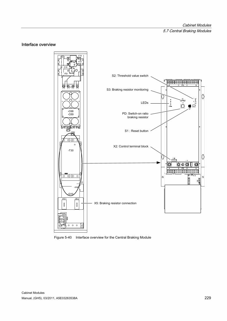
Cabinet Modules 5.7 Central Braking Modules
Cabinet Modules Manual, (GH5), 03/2011, A5E03263538A 229
Interface overview
-E240
-X10
0 -F24
PE PE
C/L +
D/L -
DC_Chop-Sich
-F19
-F20
-F22
-F21
-T30
-G10
-R68
-R69
-C68-C69
-X240
-F23
-X5.1 -X5.2
Figure 5-40 Interface overview for the Central Braking Module
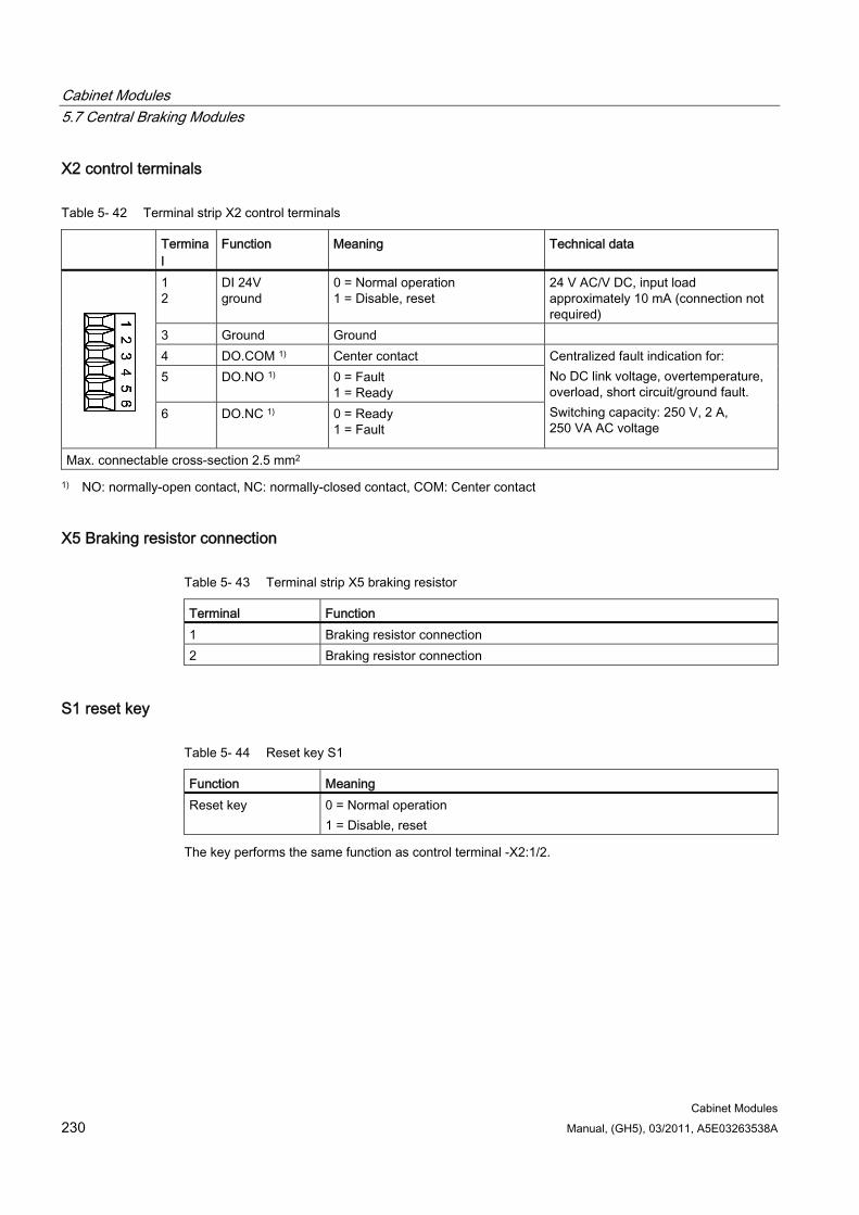
Cabinet Modules 5.7 Central Braking Modules
Cabinet Modules 230 Manual, (GH5), 03/2011, A5E03263538A
X2 control terminals
Table 5- 42 Terminal strip X2 control terminals
Terminal
Function Meaning Technical data
1 2
DI 24V ground
0 = Normal operation 1 = Disable, reset
24 V AC/V DC, input load approximately 10 mA (connection not required)
3 Ground Ground 4 DO.COM 1) Center contact 5 DO.NO 1) 0 = Fault
1 = Ready
6 DO.NC 1) 0 = Ready 1 = Fault
Centralized fault indication for: No DC link voltage, overtemperature, overload, short circuit/ground fault. Switching capacity: 250 V, 2 A, 250 VA AC voltage
Max. connectable cross-section 2.5 mm2
1) NO: normally-open contact, NC: normally-closed contact, COM: Center contact
X5 Braking resistor connection
Table 5- 43 Terminal strip X5 braking resistor
Terminal Function 1 Braking resistor connection 2 Braking resistor connection
S1 reset key
Table 5- 44 Reset key S1
Function Meaning Reset key 0 = Normal operation
1 = Disable, reset
The key performs the same function as control terminal -X2:1/2.
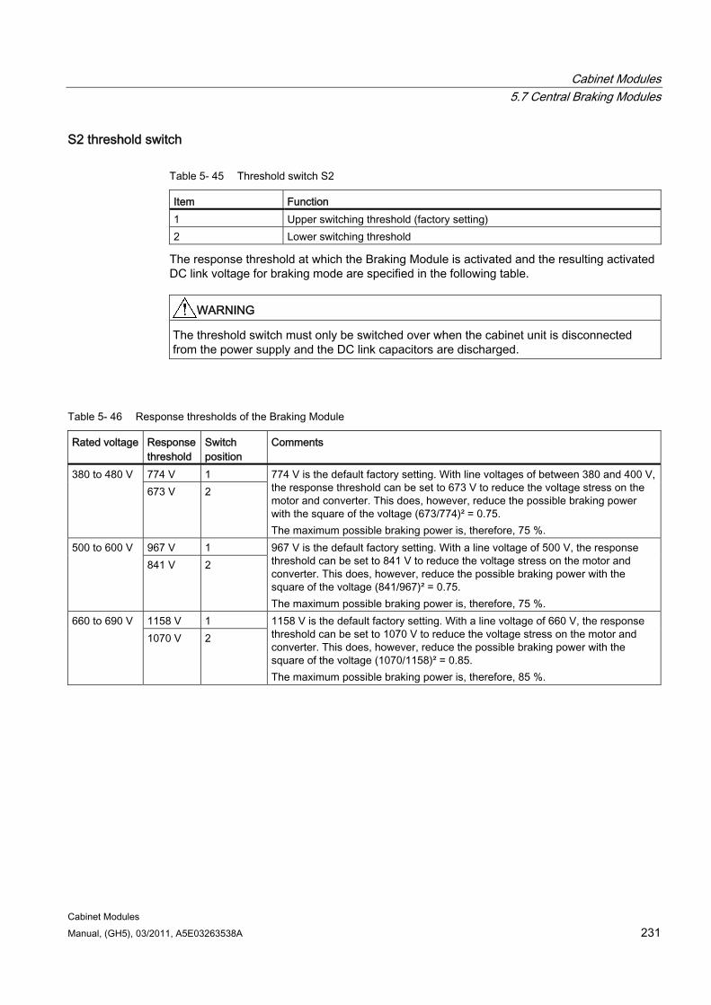
Cabinet Modules 5.7 Central Braking Modules
Cabinet Modules Manual, (GH5), 03/2011, A5E03263538A 231
S2 threshold switch
Table 5- 45 Threshold switch S2
Item Function 1 Upper switching threshold (factory setting) 2 Lower switching threshold
The response threshold at which the Braking Module is activated and the resulting activated DC link voltage for braking mode are specified in the following table.
WARNING The threshold switch must only be switched over when the cabinet unit is disconnected from the power supply and the DC link capacitors are discharged.
Table 5- 46 Response thresholds of the Braking Module
Rated voltage Response threshold
Switch position
Comments
774 V 1 380 to 480 V 673 V 2
774 V is the default factory setting. With line voltages of between 380 and 400 V, the response threshold can be set to 673 V to reduce the voltage stress on the motor and converter. This does, however, reduce the possible braking power with the square of the voltage (673/774)² = 0.75. The maximum possible braking power is, therefore, 75 %.
967 V 1 500 to 600 V 841 V 2
967 V is the default factory setting. With a line voltage of 500 V, the response threshold can be set to 841 V to reduce the voltage stress on the motor and converter. This does, however, reduce the possible braking power with the square of the voltage (841/967)² = 0.75. The maximum possible braking power is, therefore, 75 %.
1158 V 1 660 to 690 V 1070 V 2
1158 V is the default factory setting. With a line voltage of 660 V, the response threshold can be set to 1070 V to reduce the voltage stress on the motor and converter. This does, however, reduce the possible braking power with the square of the voltage (1070/1158)² = 0.85. The maximum possible braking power is, therefore, 85 %.
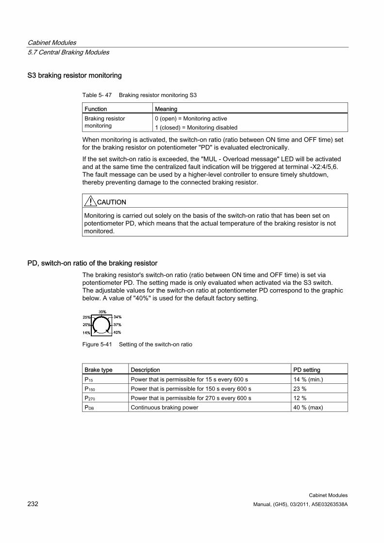
Cabinet Modules 5.7 Central Braking Modules
Cabinet Modules 232 Manual, (GH5), 03/2011, A5E03263538A
S3 braking resistor monitoring
Table 5- 47 Braking resistor monitoring S3
Function Meaning Braking resistor monitoring
0 (open) = Monitoring active 1 (closed) = Monitoring disabled
When monitoring is activated, the switch-on ratio (ratio between ON time and OFF time) set for the braking resistor on potentiometer "PD" is evaluated electronically.
If the set switch-on ratio is exceeded, the "MUL - Overload message" LED will be activated and at the same time the centralized fault indication will be triggered at terminal -X2:4/5,6. The fault message can be used by a higher-level controller to ensure timely shutdown, thereby preventing damage to the connected braking resistor.
CAUTION Monitoring is carried out solely on the basis of the switch-on ratio that has been set on potentiometer PD, which means that the actual temperature of the braking resistor is not monitored.
PD, switch-on ratio of the braking resistor The braking resistor's switch-on ratio (ratio between ON time and OFF time) is set via potentiometer PD. The setting made is only evaluated when activated via the S3 switch. The adjustable values for the switch-on ratio at potentiometer PD correspond to the graphic below. A value of "40%" is used for the default factory setting.
Figure 5-41 Setting of the switch-on ratio
Brake type Description PD setting P15 Power that is permissible for 15 s every 600 s 14 % (min.) P150 Power that is permissible for 150 s every 600 s 23 % P270 Power that is permissible for 270 s every 600 s 12 % PDB Continuous braking power 40 % (max)
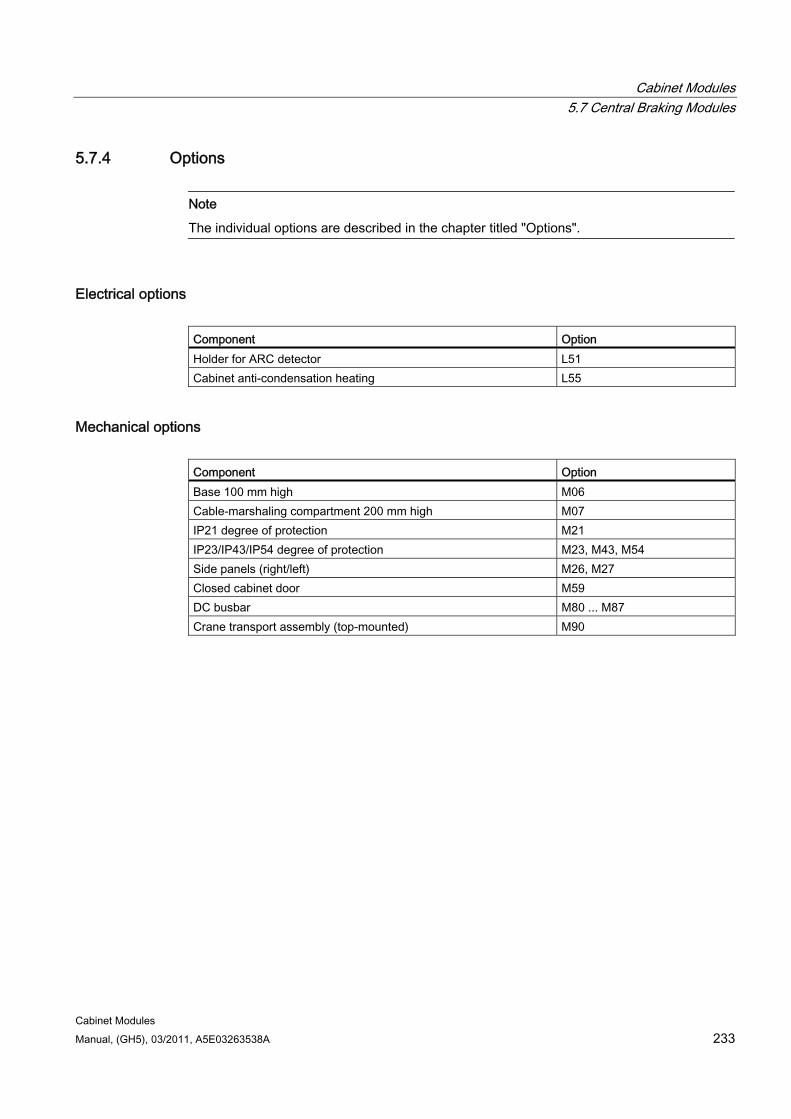
Cabinet Modules 5.7 Central Braking Modules
Cabinet Modules Manual, (GH5), 03/2011, A5E03263538A 233
5.7.4 Options
Note
The individual options are described in the chapter titled "Options".
Electrical options Component Option Holder for ARC detector L51 Cabinet anti-condensation heating L55
Mechanical options Component Option Base 100 mm high M06 Cable-marshaling compartment 200 mm high M07 IP21 degree of protection M21 IP23/IP43/IP54 degree of protection M23, M43, M54 Side panels (right/left) M26, M27 Closed cabinet door M59 DC busbar M80 ... M87 Crane transport assembly (top-mounted) M90
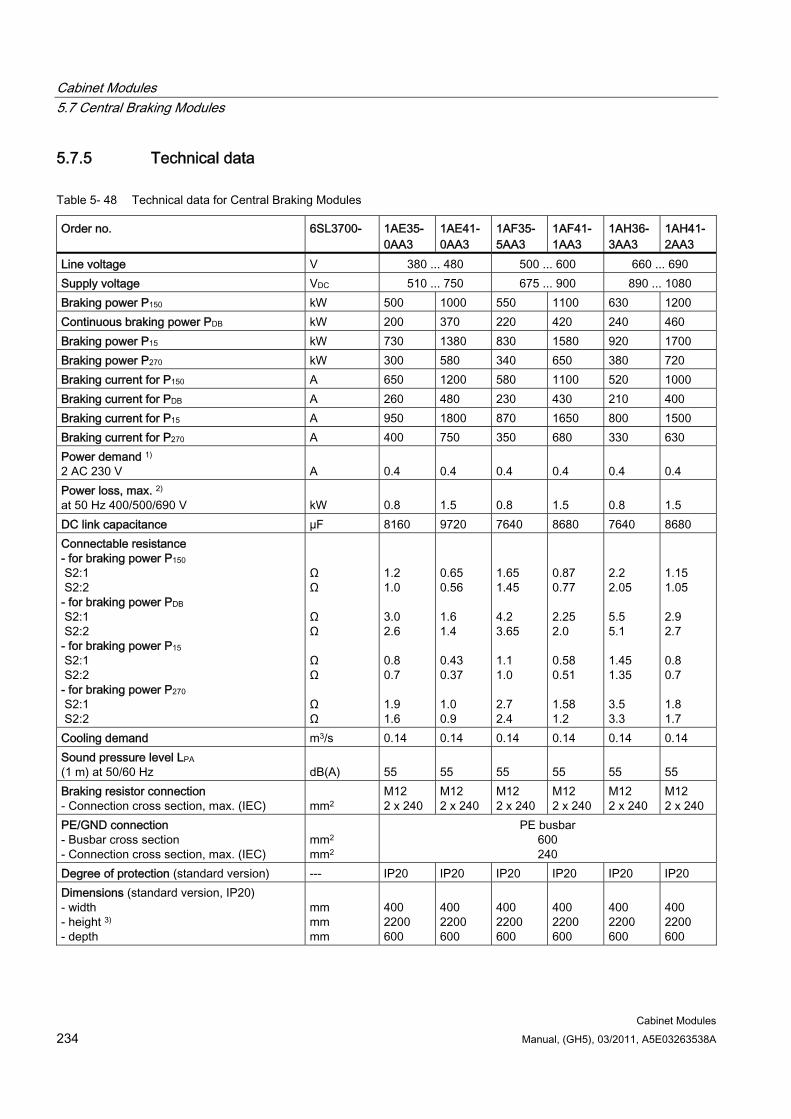
Cabinet Modules 5.7 Central Braking Modules
Cabinet Modules 234 Manual, (GH5), 03/2011, A5E03263538A
5.7.5 Technical data
Table 5- 48 Technical data for Central Braking Modules
Order no. 6SL3700- 1AE35-0AA3
1AE41-0AA3
1AF35- 5AA3
1AF41- 1AA3
1AH36- 3AA3
1AH41-2AA3
Line voltage V 380 ... 480 500 ... 600 660 ... 690 Supply voltage VDC 510 ... 750 675 ... 900 890 ... 1080 Braking power P150 kW 500 1000 550 1100 630 1200 Continuous braking power PDB kW 200 370 220 420 240 460 Braking power P15 kW 730 1380 830 1580 920 1700 Braking power P270 kW 300 580 340 650 380 720 Braking current for P150 A 650 1200 580 1100 520 1000 Braking current for PDB A 260 480 230 430 210 400 Braking current for P15 A 950 1800 870 1650 800 1500 Braking current for P270 A 400 750 350 680 330 630 Power demand 1) 2 AC 230 V
A
0.4
0.4
0.4
0.4
0.4
0.4
Power loss, max. 2) at 50 Hz 400/500/690 V
kW
0.8
1.5
0.8
1.5
0.8
1.5
DC link capacitance µF 8160 9720 7640 8680 7640 8680 Connectable resistance - for braking power P150 S2:1 S2:2 - for braking power PDB S2:1 S2:2 - for braking power P15 S2:1 S2:2 - for braking power P270 S2:1 S2:2
Ω Ω Ω Ω Ω Ω Ω Ω
1.2 1.0 3.0 2.6 0.8 0.7 1.9 1.6
0.65 0.56 1.6 1.4 0.43 0.37 1.0 0.9
1.65 1.45 4.2 3.65 1.1 1.0 2.7 2.4
0.87 0.77 2.25 2.0 0.58 0.51 1.58 1.2
2.2 2.05 5.5 5.1 1.45 1.35 3.5 3.3
1.15 1.05 2.9 2.7 0.8 0.7 1.8 1.7
Cooling demand m3/s 0.14 0.14 0.14 0.14 0.14 0.14 Sound pressure level LPA (1 m) at 50/60 Hz
dB(A)
55
55
55
55
55
55
Braking resistor connection - Connection cross section, max. (IEC)
mm2
M12 2 x 240
M12 2 x 240
M12 2 x 240
M12 2 x 240
M12 2 x 240
M12 2 x 240
PE/GND connection - Busbar cross section - Connection cross section, max. (IEC)
mm2 mm2
PE busbar 600 240
Degree of protection (standard version) --- IP20 IP20 IP20 IP20 IP20 IP20 Dimensions (standard version, IP20) - width - height 3) - depth
mm mm mm
400 2200 600
400 2200 600
400 2200 600
400 2200 600
400 2200 600
400 2200 600
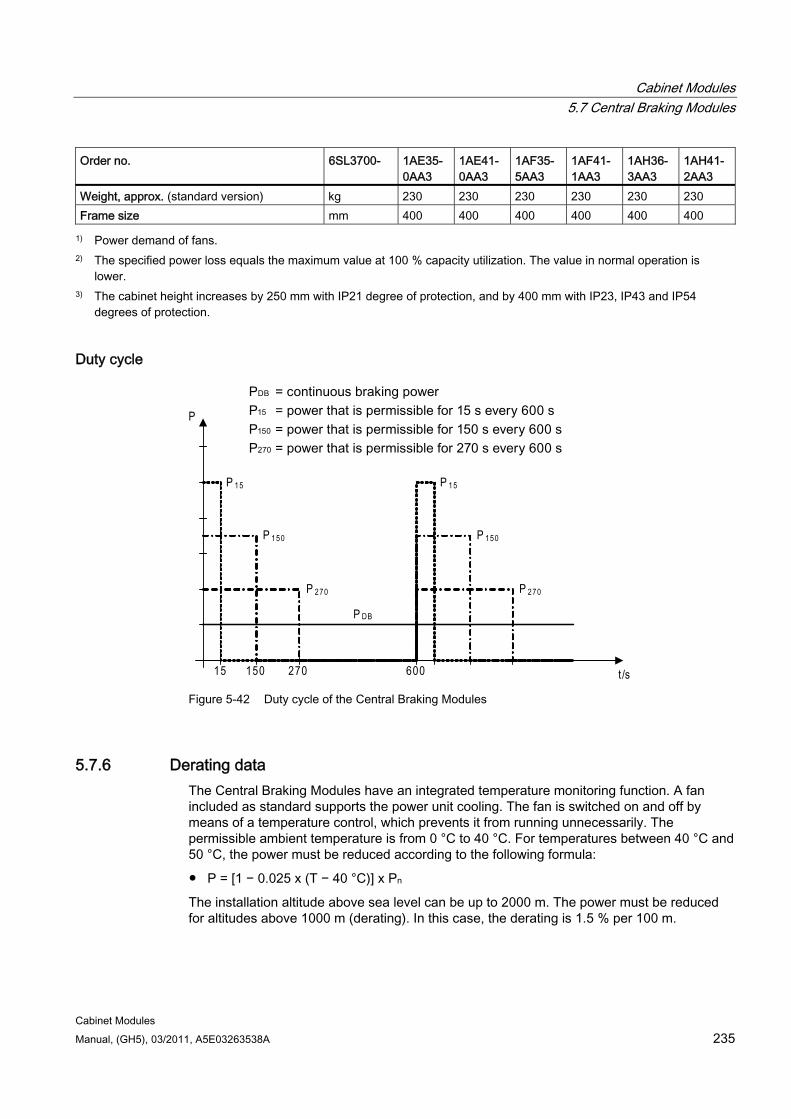
Cabinet Modules 5.7 Central Braking Modules
Cabinet Modules Manual, (GH5), 03/2011, A5E03263538A 235
Order no. 6SL3700- 1AE35-0AA3
1AE41-0AA3
1AF35- 5AA3
1AF41- 1AA3
1AH36-3AA3
1AH41-2AA3
Weight, approx. (standard version) kg 230 230 230 230 230 230 Frame size mm 400 400 400 400 400 400
1) Power demand of fans. 2) The specified power loss equals the maximum value at 100 % capacity utilization. The value in normal operation is
lower. 3) The cabinet height increases by 250 mm with IP21 degree of protection, and by 400 mm with IP23, IP43 and IP54
degrees of protection.
Duty cycle
15 150 270 600
P
t/s
P 15
P 150
P 270
P DB
P 15
P 150
P 270
Figure 5-42 Duty cycle of the Central Braking Modules
5.7.6 Derating data The Central Braking Modules have an integrated temperature monitoring function. A fan included as standard supports the power unit cooling. The fan is switched on and off by means of a temperature control, which prevents it from running unnecessarily. The permissible ambient temperature is from 0 °C to 40 °C. For temperatures between 40 °C and 50 °C, the power must be reduced according to the following formula:
P = [1 − 0.025 x (T − 40 °C)] x Pn
The installation altitude above sea level can be up to 2000 m. The power must be reduced for altitudes above 1000 m (derating). In this case, the derating is 1.5 % per 100 m.
Cabinet Modules 5.7 Central Braking Modules
Cabinet Modules 236 Manual, (GH5), 03/2011, A5E03263538A
5.7.7 Braking resistor
5.7.7.1 Description The regenerative energy of the drive line-up is dissipated via the braking resistor. The braking resistor is connected to a Braking Module. The braking resistor is positioned outside the cabinet or switchgear room. This enables the resulting heat loss to be dissipated, thereby reducing the amount of air conditioning required.
A thermostat monitors the braking resistor for overheating and, if the limit value is exceeded, it is signaled via a floating contact. The tripping temperature is 120 °C; this corresponds to a surface temperature on the resistor elements of approximately 400 °C.
Only one braking resistor may be connected to a Central Braking Module.
The power of the braking resistors is matched to the rated braking power of the Central Braking Modules; however, operation is restricted to a reduced duty cycle of 15 seconds every 20 minutes.
WARNING The thermostat contact must be connected on the plant side so that the signal can be evaluated in the Control Unit or in a higher-level controller; see the section titled "Configuring the overtemperature checkback signal".
Cabinet Modules 5.7 Central Braking Modules
Cabinet Modules Manual, (GH5), 03/2011, A5E03263538A 237
5.7.7.2 Safety information
CAUTION
The surface temperature of the braking resistors may exceed 80 °C.
CAUTION A cooling clearance of 200 mm must be maintained on all sides of the component (with ventilation grilles).
CAUTION The cables for the braking resistor must be routed to prevent short-circuits and ground faults in accordance with IEC 61800-5-2:2007, Table D.1.
This can be accomplished, for example, by: Eliminating the risk of mechanical damage to the cables Using cables with double insulation Maintaining adequate clearance, using spacers, for example Routing the cables in separate cable ducts or tubes
NOTICE A maximum cable length of 300 m is permissible between the Central Braking Module and the braking resistor.
Note
Sufficient space must be available for dissipating the energy converted by the braking resistor.
A sufficient distance from flammable objects must be ensured.
The braking resistor must be installed as a free-standing unit.
Objects must not be placed on or anywhere above the braking resistor.
The braking resistor should not be installed underneath fire-detection systems, since these could be triggered by the resulting heat.
For outdoor installation, a hood should be provided to protect the braking resistor from precipitation (in accordance with degree of protection IP21).
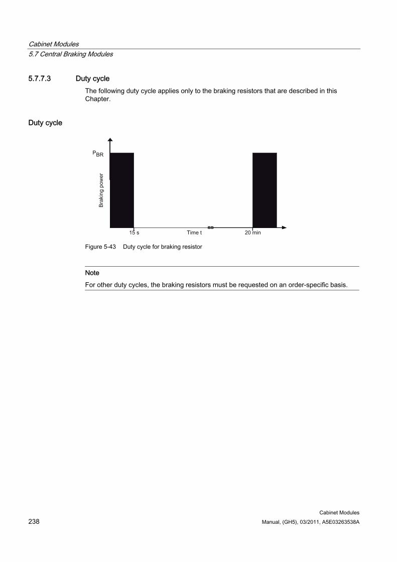
Cabinet Modules 5.7 Central Braking Modules
Cabinet Modules 238 Manual, (GH5), 03/2011, A5E03263538A
5.7.7.3 Duty cycle The following duty cycle applies only to the braking resistors that are described in this Chapter.
Duty cycle
Figure 5-43 Duty cycle for braking resistor
Note
For other duty cycles, the braking resistors must be requested on an order-specific basis.
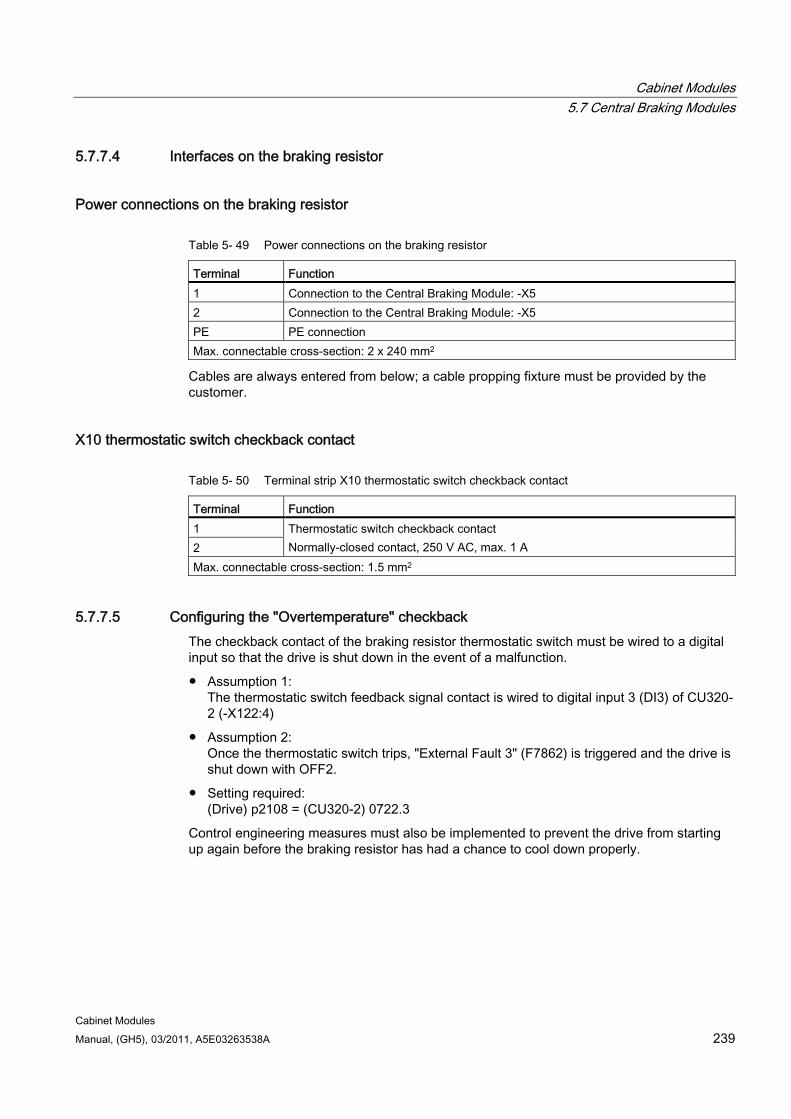
Cabinet Modules 5.7 Central Braking Modules
Cabinet Modules Manual, (GH5), 03/2011, A5E03263538A 239
5.7.7.4 Interfaces on the braking resistor
Power connections on the braking resistor
Table 5- 49 Power connections on the braking resistor
Terminal Function 1 Connection to the Central Braking Module: -X5 2 Connection to the Central Braking Module: -X5 PE PE connection Max. connectable cross-section: 2 x 240 mm2
Cables are always entered from below; a cable propping fixture must be provided by the customer.
X10 thermostatic switch checkback contact
Table 5- 50 Terminal strip X10 thermostatic switch checkback contact
Terminal Function 1 2
Thermostatic switch checkback contact Normally-closed contact, 250 V AC, max. 1 A
Max. connectable cross-section: 1.5 mm2
5.7.7.5 Configuring the "Overtemperature" checkback The checkback contact of the braking resistor thermostatic switch must be wired to a digital input so that the drive is shut down in the event of a malfunction.
Assumption 1: The thermostatic switch feedback signal contact is wired to digital input 3 (DI3) of CU320-2 (-X122:4)
Assumption 2: Once the thermostatic switch trips, "External Fault 3" (F7862) is triggered and the drive is shut down with OFF2.
Setting required: (Drive) p2108 = (CU320-2) 0722.3
Control engineering measures must also be implemented to prevent the drive from starting up again before the braking resistor has had a chance to cool down properly.
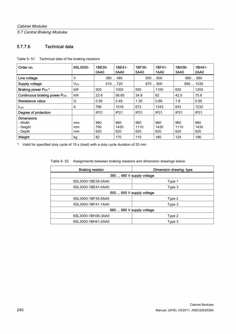
Cabinet Modules 5.7 Central Braking Modules
Cabinet Modules 240 Manual, (GH5), 03/2011, A5E03263538A
5.7.7.6 Technical data
Table 5- 51 Technical data of the braking resistors
Order no. 6SL3000- 1BE35-0AA0
1BE41-0AA0
1BF35-5AA0
1BF41-1AA0
1BH36-3AA0
1BH41-2AA0
Line voltage V 380 ... 480 500 ... 600 660 ... 690 Supply voltage VDC 510 ... 720 675 ... 900 890 ... 1035 Braking power PBR1) kW 500 1000 550 1100 630 1200 Continuous braking power PDB kW 23.8 58.65 34.8 62 42.5 75.6 Resistance value Ω 0.95 0.49 1.35 0.69 1.8 0.95 Imax A 766 1518 672 1343 643 1232 Degree of protection IP21 IP21 IP21 IP21 IP21 IP21 Dimensions - Width - Height - Depth
mm mm mm
960 790 620
960 1430 620
960 1110 620
960 1430 620
960 1110 620
960 1430 620
Weight kg 82 170 110 180 124 196
1) Valid for specified duty cycle of 15 s (load) with a duty cycle duration of 20 min.
Table 5- 52 Assignments between braking resistors and dimension drawings below
Braking resistor Dimension drawing, type 380 ... 480 V supply voltage
6SL3000-1BE35-0AA0 Type 1 6SL3000-1BE41-0AA0 Type 3
500 ... 600 V supply voltage 6SL3000-1BF35-5AA0 Type 2 6SL3000-1BF41-1AA0 Type 3
660 ... 690 V supply voltage 6SL3000-1BH36-3AA0 Type 2 6SL3000-1BH41-2AA0 Type 3
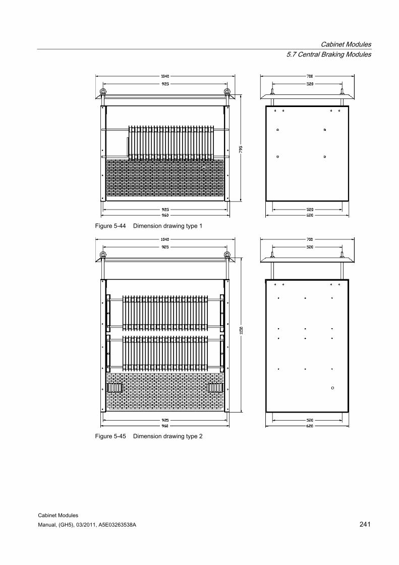
Cabinet Modules 5.7 Central Braking Modules
Cabinet Modules Manual, (GH5), 03/2011, A5E03263538A 241
Figure 5-44 Dimension drawing type 1
Figure 5-45 Dimension drawing type 2
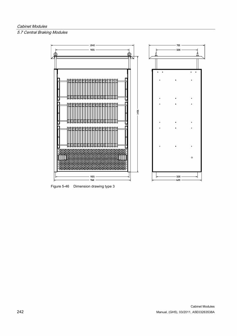
Cabinet Modules 5.7 Central Braking Modules
Cabinet Modules 242 Manual, (GH5), 03/2011, A5E03263538A
Figure 5-46 Dimension drawing type 3
Cabinet Modules 5.8 Auxiliary Power Supply Modules
Cabinet Modules Manual, (GH5), 03/2011, A5E03263538A 243
5.8 Auxiliary Power Supply Modules
5.8.1 General information
DANGER
Hazardous voltages are present in certain parts of this equipment during operation of the cabinet unit. Only qualified personnel may work on the cabinet. Such personnel must be thoroughly familiar with all the warnings and maintenance procedures for the cabinet described in the documentation provided.
The successful and safe operation of this cabinet is dependent on correct transport, proper storage and installation, as well as careful operation and maintenance. National safety regulations must be observed.
Cabinet Modules 5.8 Auxiliary Power Supply Modules
Cabinet Modules 244 Manual, (GH5), 03/2011, A5E03263538A
5.8.2 Description
Note
Refer to the layout diagrams and circuit diagrams provided on the enclosed customer DVD for the arrangement of components and interfaces, and for wiring.
Auxiliary Power Supply Modules supply power to the auxiliary power supply system of the SINAMICS S120 Cabinet Modules as well as to other external loads. The fans of the SINAMICS S120 devices installed in the Cabinet Modules are some of the devices connected to this auxiliary power supply system. In addition, the auxiliary power supply system supplies the electronics modules with external 24 V DC. This is required when the DC link is not charged in order, for example, to maintain PROFIBUS communication.
The 230 V AC power supply can also be fed in externally via an uninterruptible power supply (UPS) and terminal -X46.
NOTICE The same rated voltage must be fed into the supply infeed of the Auxiliary Power Supply Module as for the connected Cabinet Modules, as the voltage fed into the Auxiliary Power Supply Module supplies the entire system with auxiliary voltage via the auxiliary power supply system.
If a different voltage than that of the connected Cabinet Modules is fed in, there is a risk of an insufficient energy supply to the device fans or too high a voltage, which can cause damage to the system.
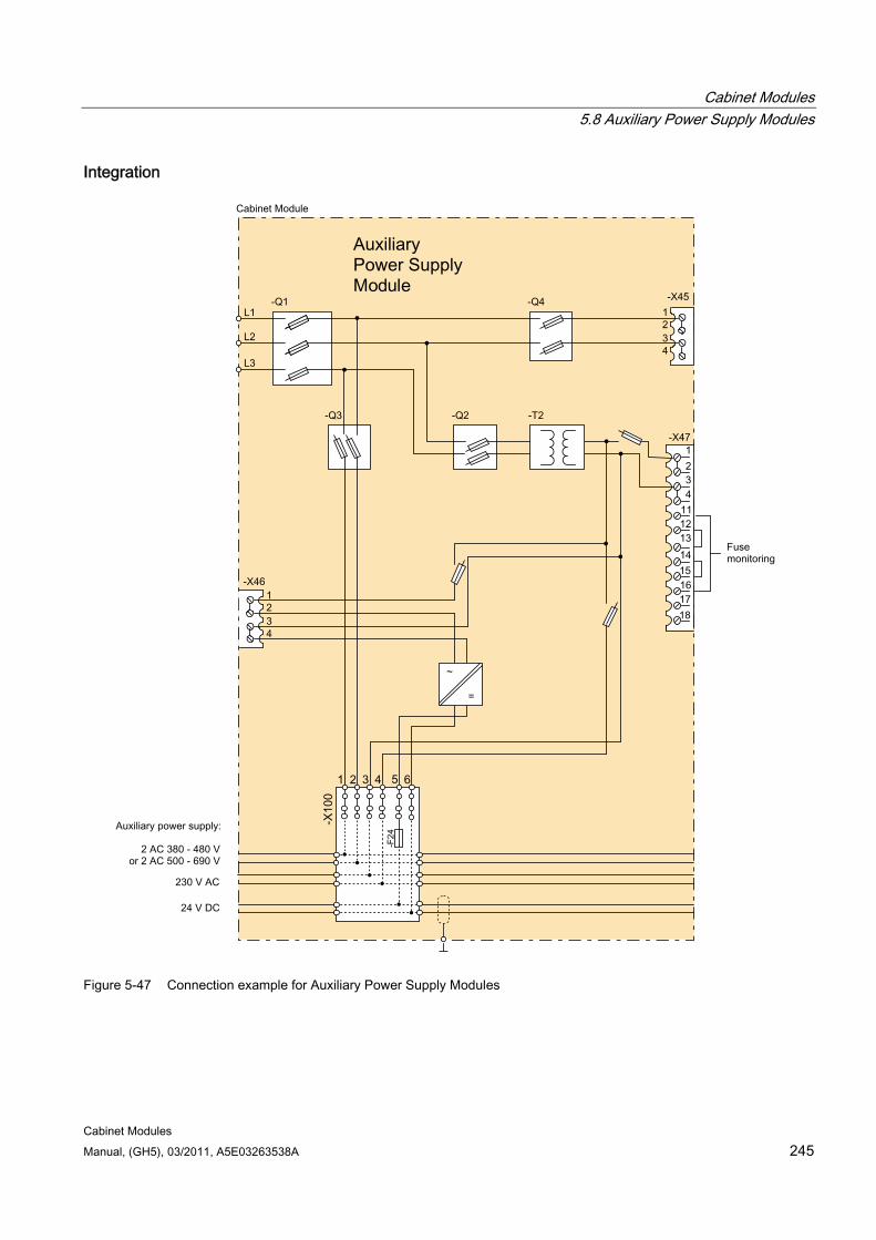
Cabinet Modules 5.8 Auxiliary Power Supply Modules
Cabinet Modules Manual, (GH5), 03/2011, A5E03263538A 245
Integration
Figure 5-47 Connection example for Auxiliary Power Supply Modules
Cabinet Modules 5.8 Auxiliary Power Supply Modules
Cabinet Modules 246 Manual, (GH5), 03/2011, A5E03263538A
Configuration The Auxiliary Power Supply Module is connected on the plant side to a voltage corresponding to the respective rated device voltage.
The standard version contains the following components:
Fuse switch disconnector with fuse monitoring for external evaluation
Supply of auxiliary power system with 3 auxiliary voltages:
– 24 V DC for the electronics power supply
– 1-ph. 230 V AC to supply 230 V AC loads
– 380 to 690 V 2 AC for supply of device fans (corresponding to the respective rated device voltage)
Transformer with output voltage 230 V 1 AC
SITOP power supply 24 V DC
PE busbar, nickel-plated (60 x 10 mm), including jumper for looping through to the next Cabinet Module.
Note
The configuration example of the Auxiliary Power Supply Module is used to illustrate the positioning of the factory-fitted components. They show the maximum possible configuration of the modules, which contain all options that can be ordered.
Refer to the layout diagrams (AO) on the customer DVD for the precise order-specific location of the components.
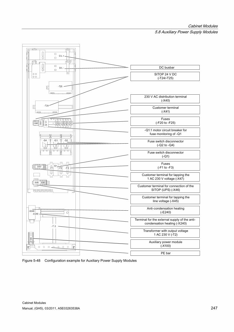
Cabinet Modules 5.8 Auxiliary Power Supply Modules
Cabinet Modules Manual, (GH5), 03/2011, A5E03263538A 247
-X45 -X46
-Q1-F 1 -F 2 -F 3
-X40 -X41
-Q4 -Q 3 -Q2
-X 47
-F25
-F20
-F21
-F22
-F23
-F24
- T25
-T 24
-Q1.1
- T 2
-E240-X 240
C/ L +
D/ L -
-X10
0PE PE
Figure 5-48 Configuration example for Auxiliary Power Supply Modules
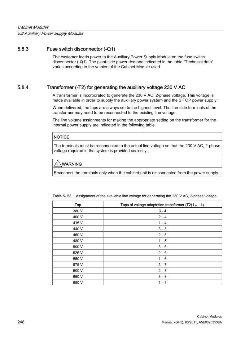
Cabinet Modules 5.8 Auxiliary Power Supply Modules
Cabinet Modules 248 Manual, (GH5), 03/2011, A5E03263538A
5.8.3 Fuse switch disconnector (-Q1) The customer feeds power to the Auxiliary Power Supply Module on the fuse switch disconnector (-Q1). The plant-side power demand indicated in the table "Technical data" varies according to the version of the Cabinet Module used.
5.8.4 Transformer (-T2) for generating the auxiliary voltage 230 V AC A transformer is incorporated to generate the 230 V AC, 2-phase voltage. This voltage is made available in order to supply the auxiliary power system and the SITOP power supply.
When delivered, the taps are always set to the highest level. The line-side terminals of the transformer may need to be reconnected to the existing line voltage.
The line voltage assignments for making the appropriate setting on the transformer for the internal power supply are indicated in the following table.
NOTICE The terminals must be reconnected to the actual line voltage so that the 230 V AC, 2-phase voltage required in the system is provided correctly.
WARNING Reconnect the terminals only when the cabinet unit is disconnected from the power supply.
Table 5- 53 Assignment of the available line voltage for generating the 230 V AC, 2-phase voltage
Tap Taps of voltage adaptation transformer (T2) LA – LB 380 V 3 - 4 400 V 2 – 4 415 V 1 – 4 440 V 3 – 5 460 V 2 – 5 480 V 1 – 5 500 V 3 – 6 525 V 2 – 6 550 V 1 – 6 575 V 3 – 7 600 V 2 – 7 660 V 3 – 8 690 V 1 – 8
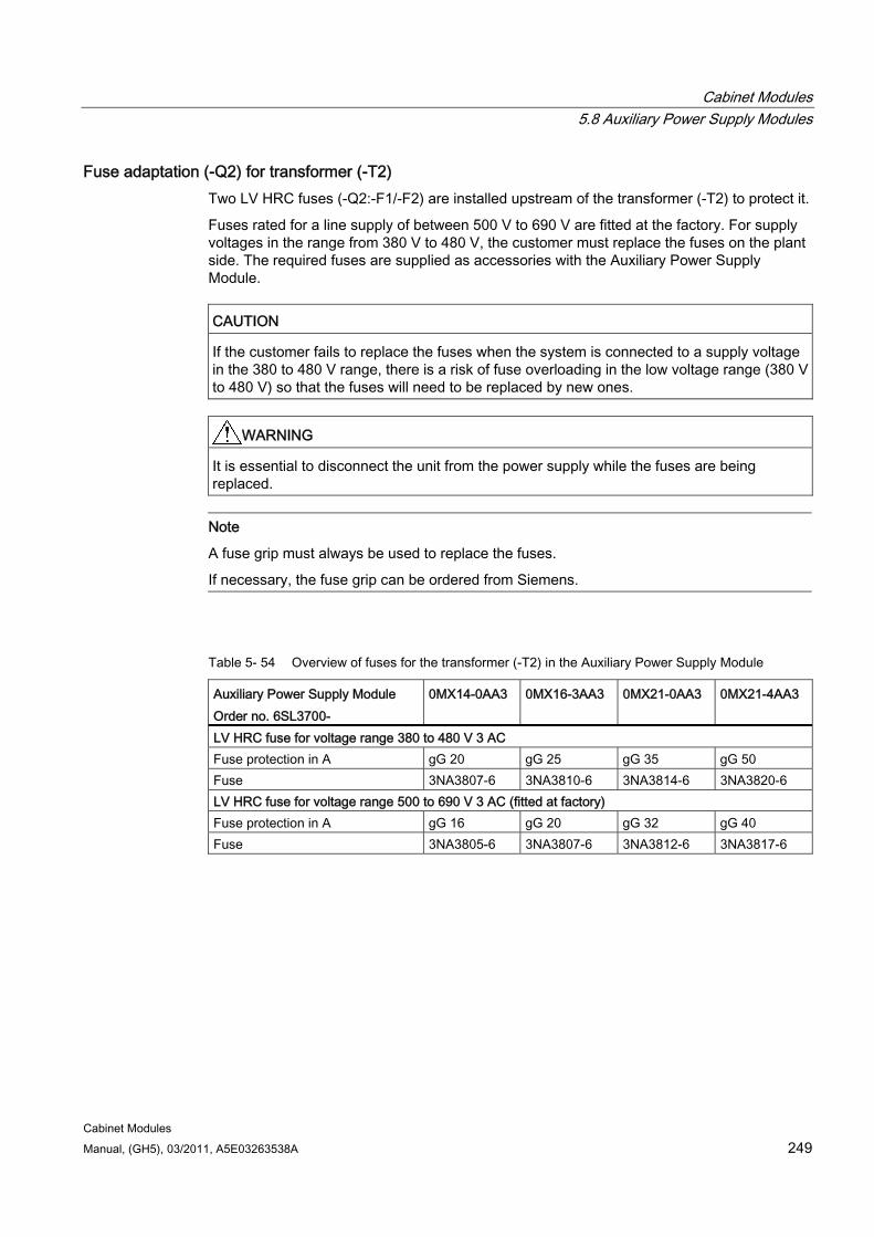
Cabinet Modules 5.8 Auxiliary Power Supply Modules
Cabinet Modules Manual, (GH5), 03/2011, A5E03263538A 249
Fuse adaptation (-Q2) for transformer (-T2) Two LV HRC fuses (-Q2:-F1/-F2) are installed upstream of the transformer (-T2) to protect it.
Fuses rated for a line supply of between 500 V to 690 V are fitted at the factory. For supply voltages in the range from 380 V to 480 V, the customer must replace the fuses on the plant side. The required fuses are supplied as accessories with the Auxiliary Power Supply Module.
CAUTION If the customer fails to replace the fuses when the system is connected to a supply voltage in the 380 to 480 V range, there is a risk of fuse overloading in the low voltage range (380 V to 480 V) so that the fuses will need to be replaced by new ones.
WARNING It is essential to disconnect the unit from the power supply while the fuses are being replaced.
Note
A fuse grip must always be used to replace the fuses.
If necessary, the fuse grip can be ordered from Siemens.
Table 5- 54 Overview of fuses for the transformer (-T2) in the Auxiliary Power Supply Module
Auxiliary Power Supply Module Order no. 6SL3700-
0MX14-0AA3 0MX16-3AA3 0MX21-0AA3 0MX21-4AA3
LV HRC fuse for voltage range 380 to 480 V 3 AC Fuse protection in A gG 20 gG 25 gG 35 gG 50 Fuse 3NA3807-6 3NA3810-6 3NA3814-6 3NA3820-6 LV HRC fuse for voltage range 500 to 690 V 3 AC (fitted at factory) Fuse protection in A gG 16 gG 20 gG 32 gG 40 Fuse 3NA3805-6 3NA3807-6 3NA3812-6 3NA3817-6

Cabinet Modules 5.8 Auxiliary Power Supply Modules
Cabinet Modules 250 Manual, (GH5), 03/2011, A5E03263538A
5.8.5 Auxiliary power supply system
Description The auxiliary power supply system is used to distribute the available voltages (line voltage for device fans, 230 V AC, 2-phase and 24 V DC). The table below shows an overview of the connected voltages and associated fuses for the auxiliary power supply system in the Auxiliary Power Supply Module. The 24 V DC voltage is provided directly from the SITOP power supply and is not protected separately by a fuse. The 24 V DC power supply itself is current-limited and short-circuit-proof at the output.
Note The 24 V DC voltage is only available via the auxiliary power supply system.
The assignment of the auxiliary power module is described in the chapter "Electrical installation", section "Connections/auxiliary power supply system".
Table 5- 55 Overview of the fuses for the auxiliary power supply system in the Auxiliary Power Supply Module
Order no. 6SL3700- 0MX14-0AA3 0MX16-3AA3 0MX21-0AA3 0MX21-4AA3 Fuse protection in A 380 to 690 V 2 AC (depending on the rated device voltage)
63 80 100 100
230 V 1 AC 6 10 10 20 24 V DC 20 40 80 80
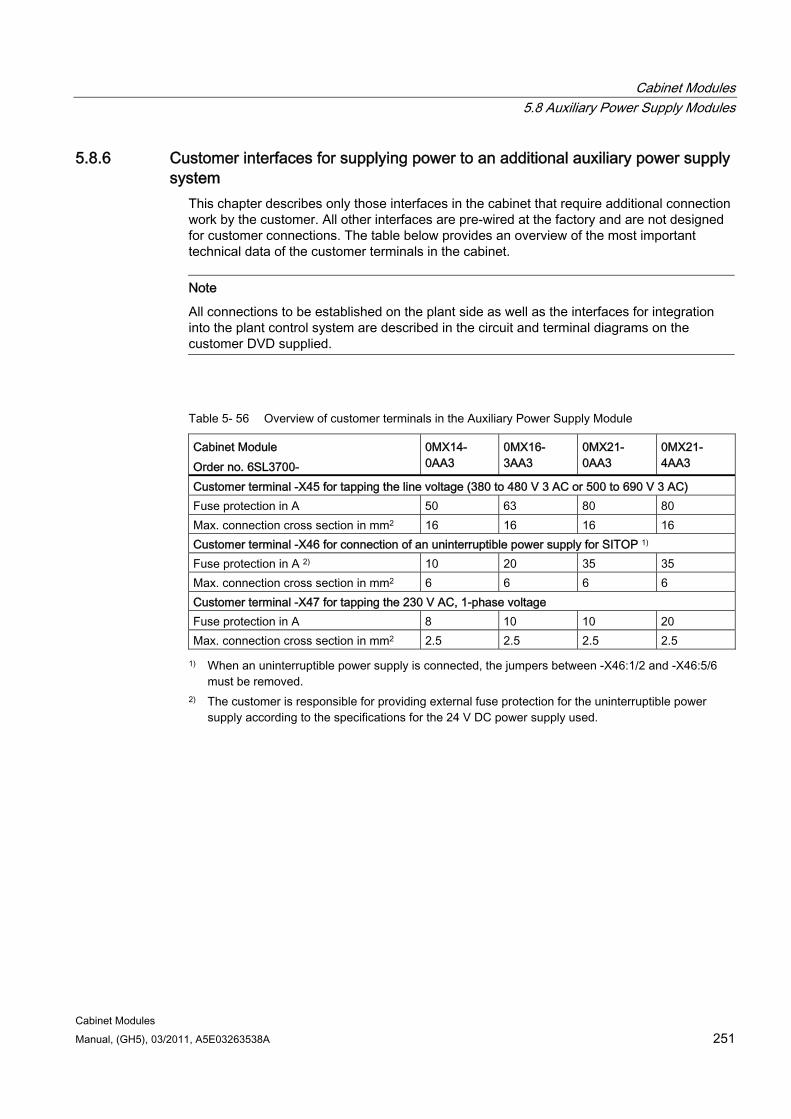
Cabinet Modules 5.8 Auxiliary Power Supply Modules
Cabinet Modules Manual, (GH5), 03/2011, A5E03263538A 251
5.8.6 Customer interfaces for supplying power to an additional auxiliary power supply system
This chapter describes only those interfaces in the cabinet that require additional connection work by the customer. All other interfaces are pre-wired at the factory and are not designed for customer connections. The table below provides an overview of the most important technical data of the customer terminals in the cabinet.
Note
All connections to be established on the plant side as well as the interfaces for integration into the plant control system are described in the circuit and terminal diagrams on the customer DVD supplied.
Table 5- 56 Overview of customer terminals in the Auxiliary Power Supply Module
Cabinet Module Order no. 6SL3700-
0MX14- 0AA3
0MX16- 3AA3
0MX21- 0AA3
0MX21- 4AA3
Customer terminal -X45 for tapping the line voltage (380 to 480 V 3 AC or 500 to 690 V 3 AC) Fuse protection in A 50 63 80 80 Max. connection cross section in mm2 16 16 16 16 Customer terminal -X46 for connection of an uninterruptible power supply for SITOP 1) Fuse protection in A 2) 10 20 35 35 Max. connection cross section in mm2 6 6 6 6 Customer terminal -X47 for tapping the 230 V AC, 1-phase voltage Fuse protection in A 8 10 10 20 Max. connection cross section in mm2 2.5 2.5 2.5 2.5
1) When an uninterruptible power supply is connected, the jumpers between -X46:1/2 and -X46:5/6 must be removed.
2) The customer is responsible for providing external fuse protection for the uninterruptible power supply according to the specifications for the 24 V DC power supply used.
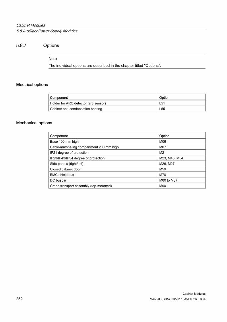
Cabinet Modules 5.8 Auxiliary Power Supply Modules
Cabinet Modules 252 Manual, (GH5), 03/2011, A5E03263538A
5.8.7 Options
Note
The individual options are described in the chapter titled "Options".
Electrical options Component Option Holder for ARC detector (arc sensor) L51 Cabinet anti-condensation heating L55
Mechanical options Component Option Base 100 mm high M06 Cable-marshaling compartment 200 mm high M07 IP21 degree of protection M21 IP23/IP43/IP54 degree of protection M23, M43, M54 Side panels (right/left) M26, M27 Closed cabinet door M59 EMC shield bus M70 DC busbar M80 to M87 Crane transport assembly (top-mounted) M90
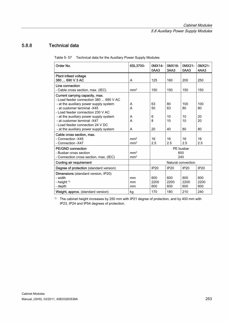
Cabinet Modules 5.8 Auxiliary Power Supply Modules
Cabinet Modules Manual, (GH5), 03/2011, A5E03263538A 253
5.8.8 Technical data
Table 5- 57 Technical data for the Auxiliary Power Supply Modules
Order No. 6SL3700- 0MX14-0AA3
0MX16-3AA3
0MX21-0AA3
0MX21-4AA3
Plant infeed voltage 380 ... 690 V 3 AC
A
125
160
200
250
Line connection - Cable cross section, max. (IEC)
mm2
150
150
150
150
Current carrying capacity, max. - Load feeder connection 380 ... 690 V AC - at the auxiliary power supply system - at customer terminal -X45 - Load feeder connection 230 V AC - at the auxiliary power supply system - at customer terminal -X47 - Load feeder connection 24 V DC - at the auxiliary power supply system
A A A A A
63 50 6 8 20
80 63 10 10 40
100 80 10 10 80
100 80 20 20 80
Cable cross section, max. - Connection -X45 - Connection -X47
mm2 mm2
16 2.5
16 2.5
16 2.5
16 2.5
PE/GND connection - Busbar cross section - Connection cross section, max. (IEC)
mm2
mm2
PE busbar 600 240
Cooling air requirement Natural convection Degree of protection (standard version) IP20 IP20 IP20 IP20 Dimensions (standard version, IP20) - width - height 1) - depth
mm mm mm
600 2200 600
600 2200 600
600 2200 600
600 2200 600
Weight, approx. (standard version) kg 170 180 210 240
1) The cabinet height increases by 250 mm with IP21 degree of protection, and by 400 mm with IP23, IP24 and IP54 degrees of protection.
Cabinet Modules 5.8 Auxiliary Power Supply Modules
Cabinet Modules 254 Manual, (GH5), 03/2011, A5E03263538A
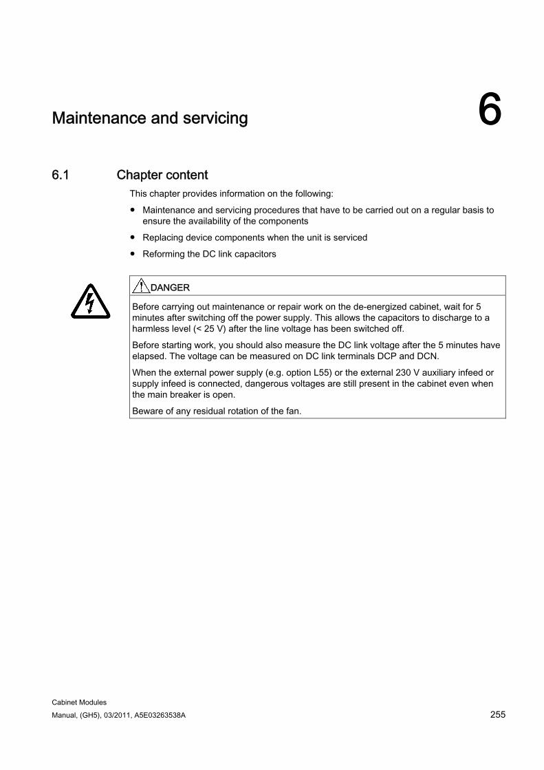
Cabinet Modules Manual, (GH5), 03/2011, A5E03263538A 255
Maintenance and servicing 66.1 Chapter content
This chapter provides information on the following:
Maintenance and servicing procedures that have to be carried out on a regular basis to ensure the availability of the components
Replacing device components when the unit is serviced
Reforming the DC link capacitors
DANGER
Before carrying out maintenance or repair work on the de-energized cabinet, wait for 5 minutes after switching off the power supply. This allows the capacitors to discharge to a harmless level (< 25 V) after the line voltage has been switched off.
Before starting work, you should also measure the DC link voltage after the 5 minutes have elapsed. The voltage can be measured on DC link terminals DCP and DCN.
When the external power supply (e.g. option L55) or the external 230 V auxiliary infeed or supply infeed is connected, dangerous voltages are still present in the cabinet even when the main breaker is open.
Beware of any residual rotation of the fan.
Maintenance and servicing 6.2 Cleaning the cabinet
Cabinet Modules 256 Manual, (GH5), 03/2011, A5E03263538A
6.2 Cleaning the cabinet The cabinet comprises mostly electronic components. Apart from the fan(s), therefore, it contains hardly any components that are subject to wear or that require maintenance or servicing. The purpose of maintenance is to preserve the specified condition of the cabinet. Dirt and contamination must be removed regularly and parts subject to wear replaced.
The following points must generally be observed.
Dust deposits Dust deposits inside the cabinet must be removed at regular intervals (or at least once a year) by qualified personnel in line with the relevant safety regulations. The unit must be cleaned using a brush and vacuum cleaner, along with dry compressed air (max. 1 bar) for areas that cannot be easily reached.
Ventilation The ventilation openings in the cabinet must never be obstructed. The fan must be checked to make sure that it is functioning correctly.
6.3 Servicing the cabinet Servicing involves activities and procedures for maintaining and restoring the operating condition of the cabinet.
Required tools The following tools are required for replacing components:
Spanner or socket spanner (width across flats 10)
Spanner or socket spanner (width across flats 13)
Spanner or socket spanner (width across flats 16/17)
Spanner or socket spanner (width across flats 18/19)
Hexagon-socket spanner (size 8)
Torque wrench up to 50 Nm
Screwdriver (size 1/2)
Screwdriver Torx T20
Screwdriver Torx T30
A socket-spanner case with two long extensions is recommended.
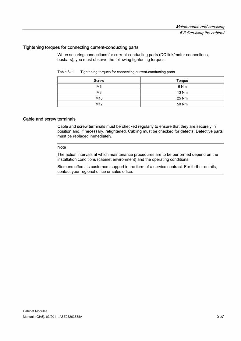
Maintenance and servicing 6.3 Servicing the cabinet
Cabinet Modules Manual, (GH5), 03/2011, A5E03263538A 257
Tightening torques for connecting current-conducting parts When securing connections for current-conducting parts (DC link/motor connections, busbars), you must observe the following tightening torques.
Table 6- 1 Tightening torques for connecting current-conducting parts
Screw Torque M6 6 Nm M8 13 Nm M10 25 Nm M12 50 Nm
Cable and screw terminals Cable and screw terminals must be checked regularly to ensure that they are securely in position and, if necessary, retightened. Cabling must be checked for defects. Defective parts must be replaced immediately.
Note
The actual intervals at which maintenance procedures are to be performed depend on the installation conditions (cabinet environment) and the operating conditions.
Siemens offers its customers support in the form of a service contract. For further details, contact your regional office or sales office.
Maintenance and servicing 6.4 Replacing components
Cabinet Modules 258 Manual, (GH5), 03/2011, A5E03263538A
6.4 Replacing components
6.4.1 General information This chapter deals with replacing components that may need to be exchanged when the cabinet units require maintenance or service. Other components are not normally subject to wear and tear and are, therefore, not covered in this chapter.
Note
The order numbers for spare parts are listed on the supplied customer DVD in the spare parts list.
Maintenance and servicing 6.4 Replacing components
Cabinet Modules Manual, (GH5), 03/2011, A5E03263538A 259
6.4.2 Safety information
Required safety precautions to be taken before carrying out maintenance and servicing
DANGER You must read and observe the "Safety information" chapter in this Manual.
When carrying out any kind of work on electrical devices, the following "five safety rules" must always be observed in accordance with EN 50110-1 and EN 50110-2: Disconnect from power supply. Protect against reconnection. Make sure that the equipment is de-energized. Ground and short-circuit. Cover or enclose adjacent components that are still live.
DANGER The following must be taken into account when the devices are transported: Some of the devices are heavy or top heavy. Due to their weight, the devices must be handled with care by trained personnel. Serious injury or even death and substantial material damage can occur if the devices
are not lifted or transported properly.
WARNING
The cabinet units are operated with high voltages. All connection work must be carried out when the cabinet is de-energized. All work on the cabinet must be carried out by trained personnel only.
Work on an open cabinet must be carried out with extreme caution because external supply voltages may be present. The power and control terminals may be live even when the motor is not running. Dangerously high voltage levels are still present inside the cabinet up to 5 minutes after it has been disconnected due to the DC link capacitors. For this reason, the cabinet should not be opened until a reasonable period of time has elapsed.
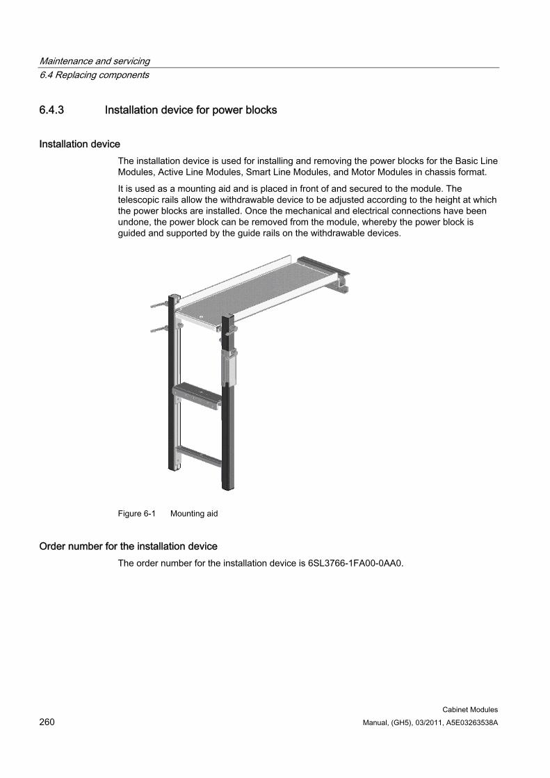
Maintenance and servicing 6.4 Replacing components
Cabinet Modules 260 Manual, (GH5), 03/2011, A5E03263538A
6.4.3 Installation device for power blocks
Installation device The installation device is used for installing and removing the power blocks for the Basic Line Modules, Active Line Modules, Smart Line Modules, and Motor Modules in chassis format.
It is used as a mounting aid and is placed in front of and secured to the module. The telescopic rails allow the withdrawable device to be adjusted according to the height at which the power blocks are installed. Once the mechanical and electrical connections have been undone, the power block can be removed from the module, whereby the power block is guided and supported by the guide rails on the withdrawable devices.
Figure 6-1 Mounting aid
Order number for the installation device The order number for the installation device is 6SL3766-1FA00-0AA0.
Maintenance and servicing 6.4 Replacing components
Cabinet Modules Manual, (GH5), 03/2011, A5E03263538A 261
6.4.4 Replacing the filter mats
Replacing the filter mats (for IP23/IP43/IP54) The filter mats must be checked at regular intervals. If the mats are too dirty to allow the air supply to flow normally, they must be replaced.
Note
If you do not replace dirty filter mats, this can cause a premature thermal shutdown of the drive.
Ordering data are available in the spare parts lists.
Preparatory steps
DANGER You must read and observe all safety information provided in this manual and always comply with the "Five safety rules" for all work on electrical equipment according to EN 50110-1 and EN 50110-2.
Observe the "five safety rules".
Disconnect the cabinet from the power supply (do not forget the external power supplies).
Allow unimpeded access to the grille area of the doors.
Note
The cabinet must be disconnected from the power supply to prevent the fans from drawing in contaminated external air. If an external power supply for the fans is used, take the coasting-down period of the fan into account or switch off the power supply.
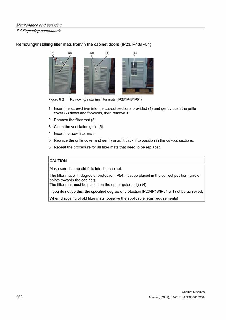
Maintenance and servicing 6.4 Replacing components
Cabinet Modules 262 Manual, (GH5), 03/2011, A5E03263538A
Removing/Installing filter mats from/in the cabinet doors (IP23/IP43/IP54)
Figure 6-2 Removing/Installing filter mats (IP23/IP43/IP54)
1. Insert the screwdriver into the cut-out sections provided (1) and gently push the grille cover (2) down and forwards, then remove it.
2. Remove the filter mat (3).
3. Clean the ventilation grille (5).
4. Insert the new filter mat.
5. Replace the grille cover and gently snap it back into position in the cut-out sections.
6. Repeat the procedure for all filter mats that need to be replaced.
CAUTION Make sure that no dirt falls into the cabinet.
The filter mat with degree of protection IP54 must be placed in the correct position (arrow points towards the cabinet). The filter mat must be placed on the upper guide edge (4).
If you do not do this, the specified degree of protection IP23/IP43/IP54 will not be achieved.
When disposing of old filter mats, observe the applicable legal requirements!
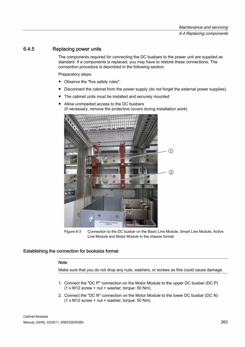
Maintenance and servicing 6.4 Replacing components
Cabinet Modules Manual, (GH5), 03/2011, A5E03263538A 263
6.4.5 Replacing power units The components required for connecting the DC busbars to the power unit are supplied as standard. If a components is replaced, you may have to restore these connections. The connection procedure is described in the following section.
Preparatory steps:
Observe the "five safety rules".
Disconnect the cabinet from the power supply (do not forget the external power supplies).
The cabinet units must be installed and securely mounted
Allow unimpeded access to the DC busbars (if necessary, remove the protective covers during installation work)
Figure 6-3 Connection to the DC busbar on the Basic Line Module, Smart Line Module, Active
Line Module and Motor Module in the chassis format
Establishing the connection for booksize format
Note
Make sure that you do not drop any nuts, washers, or screws as this could cause damage.
1. Connect the "DC P" connection on the Motor Module to the upper DC busbar (DC P) (1 x M12 screw + nut + washer; torque: 50 Nm).
2. Connect the "DC N" connection on the Motor Module to the lower DC busbar (DC N) (1 x M12 screw + nut + washer; torque: 50 Nm).
Maintenance and servicing 6.4 Replacing components
Cabinet Modules 264 Manual, (GH5), 03/2011, A5E03263538A
Establishing the connection for chassis format
WARNING The use of cables instead of the factory-installed busbars is not permitted.
Note
Make sure that you do not drop any nuts, washers, or screws as this could cause damage.
1. Connect the "DC P" connection on the Basic Line Module, Smart Line Module, Active Line Module, or Motor Module to the upper DC busbar (DC P) (1 x M12 screw + nut + washer; torque: 50 Nm).
2. Connect the "DC N" connection on the Basic Line Module, Smart Line Module, Active Line Module, or Motor Module to the lower DC busbar (DC N) (1 x M12 screw + nut + washer; torque: 50 Nm).
6.4.6 Replacing the Motor Module, booksize format
Preparatory steps Observe the "five safety rules".
Remove the protective cover.
Allow unimpeded access.
Removal 1. Disconnect the Control Unit and remove from the plate (if present).
2. Detach the cable from the plate and put to one side.
3. Remove the Control Unit plates.
4. Remove the DC link rectifier adapter.
5. Remove and insulate the 24 V terminal adapter.
6. Remove the DRIVE-CLiQ cables.
7. Remove, short-circuit, and insulate the motor cable.
8. Unscrew the fastening screws of the Motor Module (two turns only).
9. Remove the Motor Module.
Installation For installation, carry out the above steps for removal in reverse order.
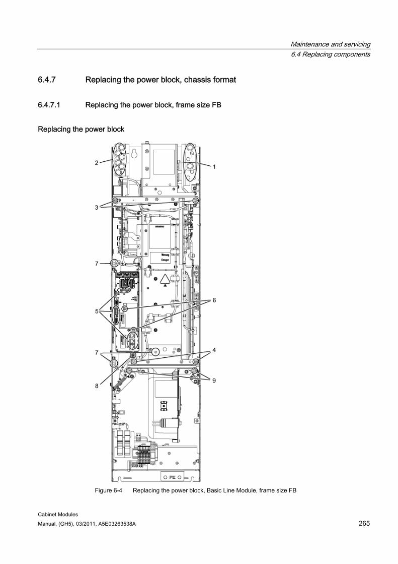
Maintenance and servicing 6.4 Replacing components
Cabinet Modules Manual, (GH5), 03/2011, A5E03263538A 265
6.4.7 Replacing the power block, chassis format
6.4.7.1 Replacing the power block, frame size FB
Replacing the power block
Figure 6-4 Replacing the power block, Basic Line Module, frame size FB
Maintenance and servicing 6.4 Replacing components
Cabinet Modules 266 Manual, (GH5), 03/2011, A5E03263538A
Preparatory steps Observe the "five safety rules".
Disconnect the cabinet from the power supply (do not forget the external power supplies).
Remove the protective cover.
Allow unimpeded access to the power block.
Set up the installation device for the power block and keep it at hand (see the section titled "Installation device for power blocks").
Removal steps The removal steps are numbered in accordance with the figure above.
1. Unscrew the connection to the DC link (4 screws).
2. Unscrew the connection to the line connection (6 screws).
3. Remove the retaining screws at the top (2 screws).
4. Remove the retaining screws at the bottom (2 screws).
5. Remove the DRIVE-CLiQ cables and connections on -X41 / -X42 / -X46 (6 plugs).
6. Take out the retaining screws for the IPD card (2 screws) and remove the IPD card from plug -X45 on the Control Interface Module.
7. Remove the mounts for the Control Interface Module (1 screw and 2 nuts) and carefully pull out the Control Interface Module.
When removing the Control Interface Module, you have to disconnect 5 further plugs one after the other (2 at the top, 3 below).
8. Disconnect the plug for the thermocouple.
9. Unscrew the 2 retaining screws for the fan and attach the tool for de-installing the power block at this position.
You can now remove the power block.
Maintenance and servicing 6.4 Replacing components
Cabinet Modules Manual, (GH5), 03/2011, A5E03263538A 267
Installation steps Installing is the same as removing, however in the reverse order.
CAUTION When removing the power block, ensure that you do not damage any signal cables.
CAUTION The tightening torques specified in the table "Tightening torques for connecting current-conducting parts" must be observed.
Carefully establish the plug connections and then ensure that they are secure.
The screw connections for the protective covers may only be tightened by hand.
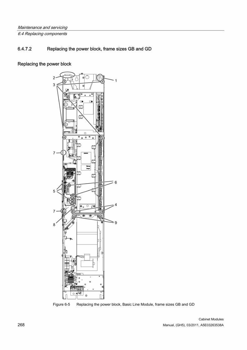
Maintenance and servicing 6.4 Replacing components
Cabinet Modules 268 Manual, (GH5), 03/2011, A5E03263538A
6.4.7.2 Replacing the power block, frame sizes GB and GD
Replacing the power block
Figure 6-5 Replacing the power block, Basic Line Module, frame sizes GB and GD
Maintenance and servicing 6.4 Replacing components
Cabinet Modules Manual, (GH5), 03/2011, A5E03263538A 269
Preparatory steps Observe the "five safety rules".
Disconnect the cabinet from the power supply (do not forget the external power supplies).
Remove the protective cover.
Allow unimpeded access to the power block.
Set up the installation device for the power block and keep it at hand (see the section titled "Installation device for power blocks").
Removal steps The removal steps are numbered in accordance with the figure above.
1. Unscrew the connection to the DC link (6 screws).
2. Unscrew the connection to the line connection (9 screws).
3. Remove the retaining screws at the top (4 screws).
4. Remove the retaining screws at the bottom (2 screws).
5. Remove the DRIVE-CLiQ cables and connections on -X41 / -X42 / -X46 (6 plugs).
6. Take out the retaining screws for the IPD card (2 screws) and remove the IPD card from plug -X45 on the Control Interface Module.
7. Remove the mounts for the Control Interface Module (2 nuts) and carefully pull out the Control Interface Module.
When removing the Control Interface Module, you have to disconnect 5 further plugs one after the other (2 at the top, 3 below).
8. Disconnect the plug for the thermocouple.
9. Unscrew the 2 retaining screws for the fan and attach the tool for de-installing the power block at this position.
You can now remove the power block.
CAUTION When removing the power block, ensure that you do not damage any signal cables.
Maintenance and servicing 6.4 Replacing components
Cabinet Modules 270 Manual, (GH5), 03/2011, A5E03263538A
Installation steps For installation, carry out the above steps for removal in reverse order.
CAUTION The tightening torques specified in the table "Tightening torques for connecting current-conducting parts" must be observed.
Carefully establish the plug connections and then ensure that they are secure.
The screw connections for the protective covers may only be tightened by hand.
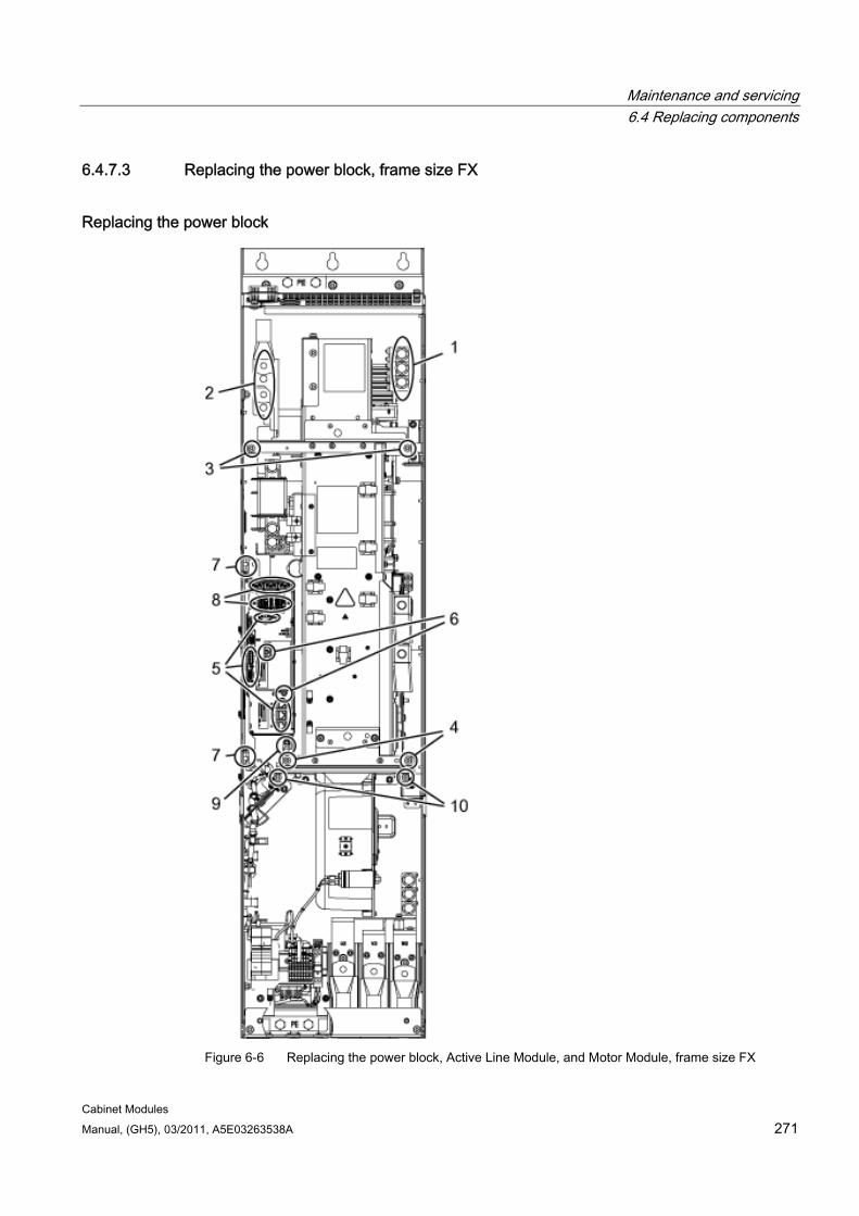
Maintenance and servicing 6.4 Replacing components
Cabinet Modules Manual, (GH5), 03/2011, A5E03263538A 271
6.4.7.3 Replacing the power block, frame size FX
Replacing the power block
Figure 6-6 Replacing the power block, Active Line Module, and Motor Module, frame size FX
Maintenance and servicing 6.4 Replacing components
Cabinet Modules 272 Manual, (GH5), 03/2011, A5E03263538A
Preparatory steps Observe the "five safety rules".
Disconnect the cabinet from the power supply (do not forget the external power supplies).
Remove the protective cover.
Allow unimpeded access to the power block.
Set up the installation device for the power block and keep it at hand (see the section titled "Installation device for power blocks").
Removal steps The removal steps are numbered in accordance with the figure.
1. Unscrew the connection to the line or to the motor (3 screws).
2. Unscrew the connection to the DC link (4 screws).
3. Remove the retaining screws at the top (2 screws).
4. Remove the retaining screws at the bottom (2 screws).
5. Remove the DRIVE-CLiQ cables and connections on -X41 / -X42 / -X46 (6 plugs).
6. Take out the retaining screws for the IPD card (2 screws) and remove the IPD card from plug -X45 on the Control Interface Module.
7. Remove the mounts for the Control Interface Module (2 nuts) and carefully pull out the Control Interface Module.
When removing the Control Interface Module, you have to disconnect 5 further plugs one after the other (2 at the top, 3 below).
8. Disconnect the plug-in connections for the fiber optic cables and signal cables (5 connectors).
9. Disconnect the plug for the thermocouple.
10. Unscrew the 2 retaining screws for the fan and attach the tool for de-installing the power block at this position.
You can now remove the power block.
DANGER
Up to 1200 V may still be present on the DC busbars even after the DC interface (option L37) has been switched off. For this reason, take particular care to avoid coming into contact with the DC busbar when replacing a power block!
CAUTION When removing the power block, ensure that you do not damage any signal cables.
The second plug connection for the fiber optic cables cannot be disconnected until the power block has been pulled out slightly (see Step 7).
Maintenance and servicing 6.4 Replacing components
Cabinet Modules Manual, (GH5), 03/2011, A5E03263538A 273
Installation steps Installing is the same as removing, however in the reverse order.
CAUTION The tightening torques specified in the table "Tightening torques for connecting current-conducting parts" must be observed.
Carefully establish the plug connections and then ensure that they are secure.
The fiber optic cable plugs must be remounted at their original slot. Fiber optic cables and sockets are accordingly labeled for correct assignment (U11, U21, U31).
The screw connections for the protective covers may only be tightened by hand.
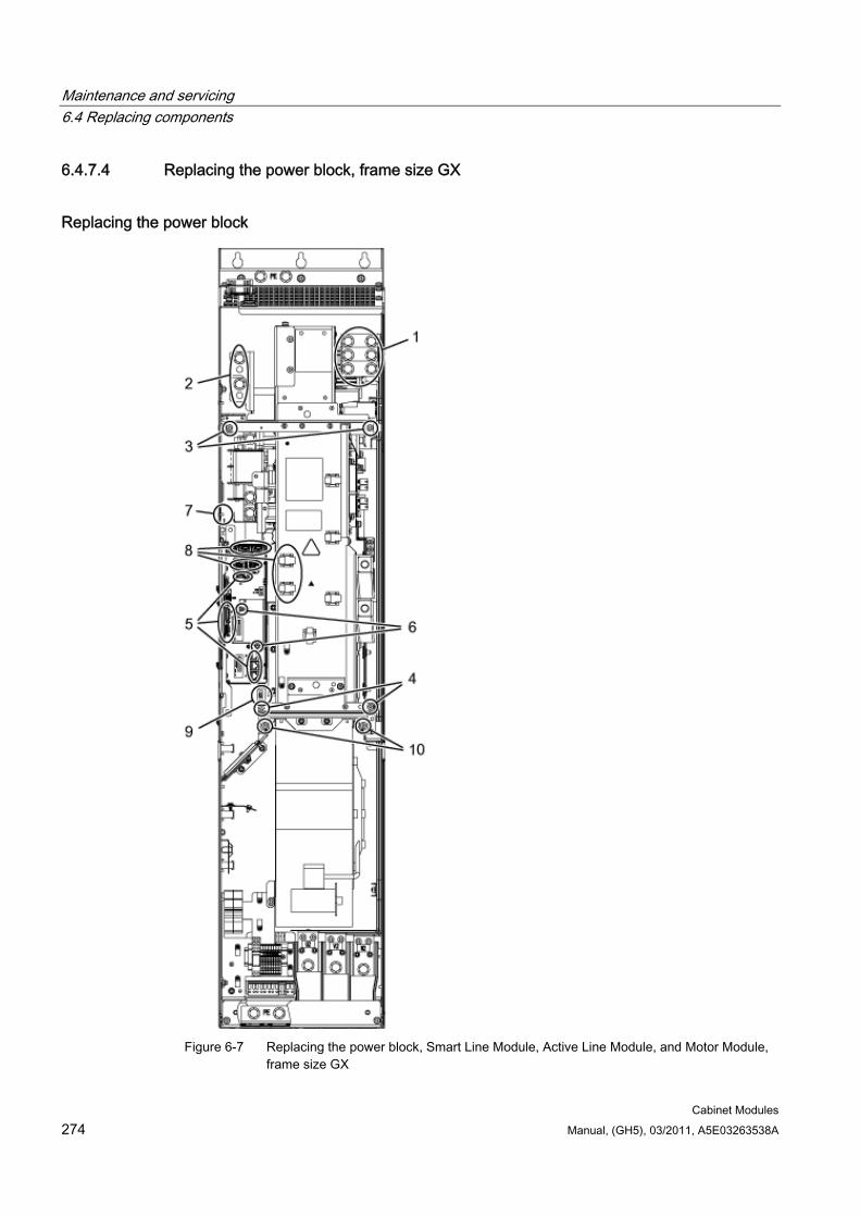
Maintenance and servicing 6.4 Replacing components
Cabinet Modules 274 Manual, (GH5), 03/2011, A5E03263538A
6.4.7.4 Replacing the power block, frame size GX
Replacing the power block
Figure 6-7 Replacing the power block, Smart Line Module, Active Line Module, and Motor Module,
frame size GX
Maintenance and servicing 6.4 Replacing components
Cabinet Modules Manual, (GH5), 03/2011, A5E03263538A 275
Preparatory steps Observe the "five safety rules".
Disconnect the cabinet from the power supply (do not forget the external power supplies).
Remove the protective cover.
Allow unimpeded access to the power block.
Set up the installation device for the power block and keep it at hand (see the section titled "Installation device for power blocks").
Removal steps The removal steps are numbered in accordance with the figure.
1. Unscrew the connection to the line or to the motor (3 screws).
2. Unscrew the connection to the DC link (4 screws).
3. Remove the retaining screws at the top (2 screws).
4. Remove the retaining screws at the bottom (2 screws).
5. Remove the DRIVE-CLiQ cables and connections on -X41 / -X42 / -X46 (6 plugs).
6. Take out the retaining screws for the IPD card (2 screws) and remove the IPD card from plug -X45 on the Control Interface Module.
7. Remove the mount for the Control Interface Module (1 nut) and carefully pull out the Control Interface Module.
When removing the Control Interface Module, you have to disconnect 5 further plugs one after the other (2 at the top, 3 below).
8. Disconnect the plug connections for the fiber optic cables and signal cables (5 plugs) and release the cable connectors for the signal cables (2 connectors).
9. Disconnect the plug for the thermocouple.
10. Unscrew the 2 retaining screws for the fan and attach the tool for de-installing the power block at this position.
You can now remove the power block.
DANGER
Up to 1200 V may still be present on the DC busbars even after the DC interface (option L37) has been switched off. For this reason, take particular care to avoid coming into contact with the DC busbar when replacing a power block!
CAUTION When removing the power block, ensure that you do not damage any signal cables.
The second plug connection for the fiber optic cables cannot be disconnected until the power block has been pulled out slightly (see Step 7).
Maintenance and servicing 6.4 Replacing components
Cabinet Modules 276 Manual, (GH5), 03/2011, A5E03263538A
Installation steps Installing is the same as removing, however in the reverse order.
CAUTION The tightening torques specified in the table "Tightening torques for connecting current-conducting parts" must be observed.
Carefully establish the plug connections and then ensure that they are secure.
The fiber optic cable plugs must be remounted at their original slot. Fiber optic cables and sockets are accordingly labeled for correct assignment (U11, U21, U31).
The screw connections for the protective covers may only be tightened by hand.
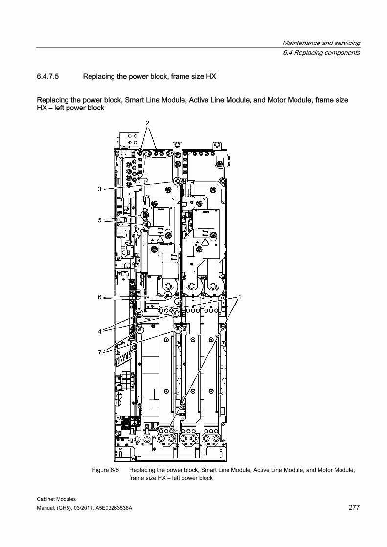
Maintenance and servicing 6.4 Replacing components
Cabinet Modules Manual, (GH5), 03/2011, A5E03263538A 277
6.4.7.5 Replacing the power block, frame size HX
Replacing the power block, Smart Line Module, Active Line Module, and Motor Module, frame size HX – left power block
Figure 6-8 Replacing the power block, Smart Line Module, Active Line Module, and Motor Module,
frame size HX – left power block
Maintenance and servicing 6.4 Replacing components
Cabinet Modules 278 Manual, (GH5), 03/2011, A5E03263538A
Preparatory steps Observe the "five safety rules".
Disconnect the cabinet from the power supply (do not forget the external power supplies).
Remove the protective cover.
Allow unimpeded access to the power block.
Set up the installation device for the power block and keep it at hand (see the section titled "Installation device for power blocks").
Removal steps The removal steps are numbered in accordance with the figure above.
1. Remove the busbar (6 screws).
2. Unscrew the connection to the DC link (8 nuts).
3. Remove the retaining screw at the top (1 screw).
4. Remove the retaining screws at the bottom (2 screws).
5. Disconnect the plug connections for the fiber optic cables and signal cables (2 plugs).
6. Remove the connection for the current transformer and associated PE connection (1 plug).
7. Unscrew the 2 retaining screws for the fan and attach the installation device for the power block at this position.
You can now remove the power block.
DANGER
Up to 1200 V may still be present on the DC busbars even after the DC interface (option L37) has been switched off. For this reason, take particular care to avoid coming into contact with the DC busbar when replacing a power block!
CAUTION When removing the power block, ensure that you do not damage any signal cables.
The second plug connection for the fiber optic cables cannot be disconnected until the power block has been pulled out slightly (see Step 5).

Maintenance and servicing 6.4 Replacing components
Cabinet Modules Manual, (GH5), 03/2011, A5E03263538A 279
Installation steps Installing is the same as removing, however in the reverse order.
CAUTION The tightening torques specified in the table "Tightening torques for connecting current-conducting parts" must be observed.
Carefully establish the plug connections and then ensure that they are secure.
The fiber optic cable plugs must be remounted at their original slot. Fiber optic cables and sockets are accordingly labeled for correct assignment (U11, U21, U31).
The screw connections for the protective covers may only be tightened by hand.
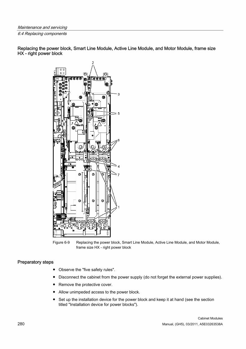
Maintenance and servicing 6.4 Replacing components
Cabinet Modules 280 Manual, (GH5), 03/2011, A5E03263538A
Replacing the power block, Smart Line Module, Active Line Module, and Motor Module, frame size HX - right power block
Figure 6-9 Replacing the power block, Smart Line Module, Active Line Module, and Motor Module,
frame size HX - right power block
Preparatory steps Observe the "five safety rules".
Disconnect the cabinet from the power supply (do not forget the external power supplies).
Remove the protective cover.
Allow unimpeded access to the power block.
Set up the installation device for the power block and keep it at hand (see the section titled "Installation device for power blocks").
Maintenance and servicing 6.4 Replacing components
Cabinet Modules Manual, (GH5), 03/2011, A5E03263538A 281
Removal steps The removal steps are numbered in accordance with the figure above.
1. Remove the busbars (12 screws).
2. Unscrew the connection to the DC link (8 nuts).
3. Remove the retaining screw at the top (1 screw).
4. Remove the retaining screws at the bottom (2 screws).
5. Disconnect the plug connections for the fiber optic cables and signal cables (2 plugs). The second plug connection for the fiber optic cables cannot be disconnected until the power block has been pulled out slightly.
6. Remove the connection for the current transformer and associated PE connection (2 connectors).
7. Unscrew the 2 retaining screws for the fan and attach the installation device for the power block at this position.
You can now remove the power block.
DANGER
Up to 1200 V may still be present on the DC busbars even after the DC interface (option L37) has been switched off. For this reason, take particular care to avoid coming into contact with the DC busbar when replacing a power block!
CAUTION When removing the power block, ensure that you do not damage any signal cables.
The second plug connection for the fiber optic cables cannot be disconnected until the power block has been pulled out slightly (see Step 5).
Installation steps Installing is the same as removing, however in the reverse order.
CAUTION The tightening torques specified in the table "Tightening torques for connecting current-conducting parts" must be observed.
Carefully establish the plug connections and then ensure that they are secure.
The fiber optic cable plugs must be remounted at their original slot. Fiber optic cables and sockets are accordingly labeled for correct assignment (U11, U21, U31).
The screw connections for the protective covers may only be tightened by hand.
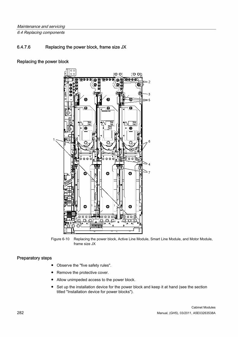
Maintenance and servicing 6.4 Replacing components
Cabinet Modules 282 Manual, (GH5), 03/2011, A5E03263538A
6.4.7.6 Replacing the power block, frame size JX
Replacing the power block
Figure 6-10 Replacing the power block, Active Line Module, Smart Line Module, and Motor Module,
frame size JX
Preparatory steps Observe the "five safety rules".
Remove the protective cover.
Allow unimpeded access to the power block.
Set up the installation device for the power block and keep it at hand (see the section titled "Installation device for power blocks").
Maintenance and servicing 6.4 Replacing components
Cabinet Modules Manual, (GH5), 03/2011, A5E03263538A 283
Removal steps The removal steps are numbered in accordance with the figure above.
1. Remove the busbar (8 screws).
2. Unscrew the connection to the DC link (8 nuts).
3. Remove the retaining screw at the top (1 screw).
4. Remove the retaining screws at the bottom (2 screws).
5. Disconnect the plug connections for the fiber optic cables and signal cables (2 plugs).
6. Remove the connection for the current transformer and associated PE connection (1 plug).
7. Unscrew the 2 retaining screws for the fan and attach the installation device for the power block at this position.
You can now remove the power block.
DANGER
Up to 1200 V may still be present on the DC busbars even after the DC interface (option L37) has been switched off. For this reason, take particular care to avoid coming into contact with the DC busbar when replacing a power block!
CAUTION When removing the power block, ensure that you do not damage any signal cables.
Installation steps Installing is the same as removing, however in the reverse order.
CAUTION The tightening torques specified in the table "Tightening torques for connecting current-conducting parts" must be observed.
Carefully establish the plug connections and then ensure that they are secure.
The fiber optic cable plugs must be remounted at their original slot. Fiber optic cables and sockets are accordingly labeled for correct assignment (U11, U21, U31).
The screw connections for the protective covers may only be tightened by hand.
The procedure described here for replacing the power block refers to the module on the right. The other modules are handled in the same way.
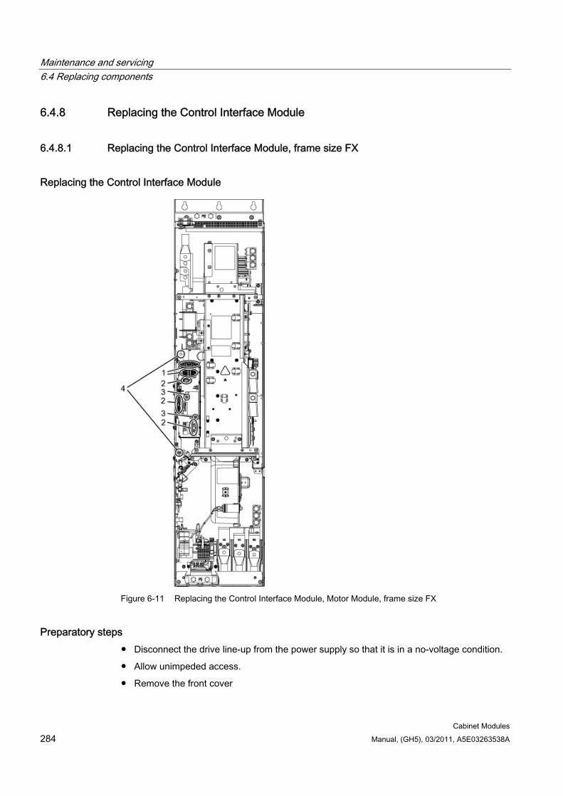
Maintenance and servicing 6.4 Replacing components
Cabinet Modules 284 Manual, (GH5), 03/2011, A5E03263538A
6.4.8 Replacing the Control Interface Module
6.4.8.1 Replacing the Control Interface Module, frame size FX
Replacing the Control Interface Module
Figure 6-11 Replacing the Control Interface Module, Motor Module, frame size FX
Preparatory steps Disconnect the drive line-up from the power supply so that it is in a no-voltage condition.
Allow unimpeded access.
Remove the front cover
Maintenance and servicing 6.4 Replacing components
Cabinet Modules Manual, (GH5), 03/2011, A5E03263538A 285
Removal steps The removal steps are numbered in accordance with the figure.
1. Disconnect the plug-in connections for the fiber optic cables and signal cables (5 connectors).
2. Remove the DRIVE-CLiQ cables and connections on -X41 / -X42 / -X46 (6 plugs).
3. Take out the retaining screws for the IPD card (2 screws) and remove the IPD card from plug -X45 on the Control Interface Module.
4. Remove the retaining screws for the Control Interface Module (2 screws).
When removing the Control Interface Module, you have to disconnect 5 further plugs one after the other (2 at the top, 3 below).
CAUTION When withdrawing it, ensure that you do not damage any signal cables.
Installation steps Installing is the same as removing, however in the reverse order.
CAUTION The tightening torques specified in the table "Tightening torques for connecting current-conducting parts" must be observed.
Carefully establish the plug connections and then ensure that they are secure.
The fiber optic cable plugs must be remounted at their original slot. Fiber optic cables and sockets are accordingly labeled for correct assignment (U11, U21, U31).
Note
It is only possible to connect identical power units in parallel if both power units have the same hardware version. Mixed operation between a power unit with Control Interface Module and a power unit with Control Interface Board is not possible.
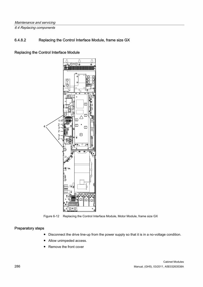
Maintenance and servicing 6.4 Replacing components
Cabinet Modules 286 Manual, (GH5), 03/2011, A5E03263538A
6.4.8.2 Replacing the Control Interface Module, frame size GX
Replacing the Control Interface Module
Figure 6-12 Replacing the Control Interface Module, Motor Module, frame size GX
Preparatory steps Disconnect the drive line-up from the power supply so that it is in a no-voltage condition.
Allow unimpeded access.
Remove the front cover

Maintenance and servicing 6.4 Replacing components
Cabinet Modules Manual, (GH5), 03/2011, A5E03263538A 287
Removal steps The removal steps are numbered in accordance with the figure.
1. Disconnect the plug-in connections for the fiber optic cables and signal cables (5 connectors).
2. Remove the DRIVE-CLiQ cables and connections on -X41 / -X42 / -X46 (6 plugs).
3. Take out the retaining screws for the IPD card (2 screws) and remove the IPD card from plug -X45 on the Control Interface Module.
4. Remove the retaining screws for the Control Interface Module (2 screws).
When removing the Control Interface Module, you have to disconnect 5 further plugs one after the other (2 at the top, 3 below).
CAUTION When withdrawing it, ensure that you do not damage any signal cables.
Installation steps Installing is the same as removing, however in the reverse order.
CAUTION The tightening torques specified in the table "Tightening torques for connecting current-conducting parts" must be observed.
Carefully establish the plug connections and then ensure that they are secure.
The fiber optic cable plugs must be remounted at their original slot. Fiber optic cables and sockets are accordingly labeled for correct assignment (U11, U21, U31).
Note
It is only possible to connect identical power units in parallel if both power units have the same hardware version. Mixed operation between a power unit with Control Interface Module and a power unit with Control Interface Board is not possible.
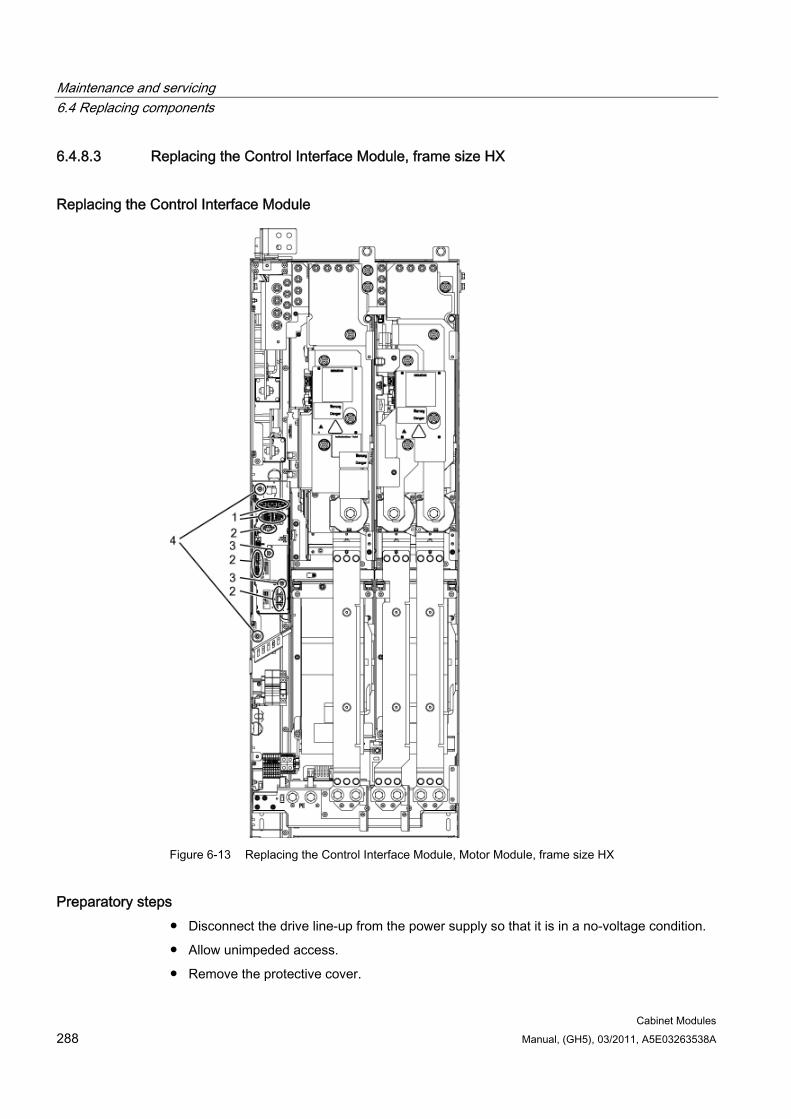
Maintenance and servicing 6.4 Replacing components
Cabinet Modules 288 Manual, (GH5), 03/2011, A5E03263538A
6.4.8.3 Replacing the Control Interface Module, frame size HX
Replacing the Control Interface Module
Figure 6-13 Replacing the Control Interface Module, Motor Module, frame size HX
Preparatory steps Disconnect the drive line-up from the power supply so that it is in a no-voltage condition.
Allow unimpeded access.
Remove the protective cover.
Maintenance and servicing 6.4 Replacing components
Cabinet Modules Manual, (GH5), 03/2011, A5E03263538A 289
Removal steps The removal steps are numbered in accordance with the figure.
1. Disconnect the plug-in connections for the fiber optic cables and signal cables (5 connectors).
2. Remove the DRIVE-CLiQ cables and connections on -X41 / -X42 / -X46 (6 plugs).
3. Take out the retaining screws for the IPD card (2 screws) and remove the IPD card from plug -X45 on the Control Interface Module.
4. Remove the retaining screws for the Control Interface Module (2 screws).
When removing the Control Interface Module, you have to disconnect 5 further plugs one after the other (2 at the top, 3 below).
CAUTION When withdrawing it, ensure that you do not damage any signal cables.
Installation steps Installing is the same as removing, however in the reverse order.
CAUTION The tightening torques specified in the table "Tightening torques for connecting current-conducting parts" must be observed.
Carefully establish the plug connections and then ensure that they are secure.
The screw connections for the protective covers may only be tightened by hand.
The fiber optic cable plugs must be remounted at their original slot. Fiber optic cables and sockets are accordingly labeled for correct assignment (U11, U21, U31).
Note
It is only possible to connect identical power units in parallel if both power units have the same hardware version. Mixed operation between a power unit with Control Interface Module and a power unit with Control Interface Board is not possible.
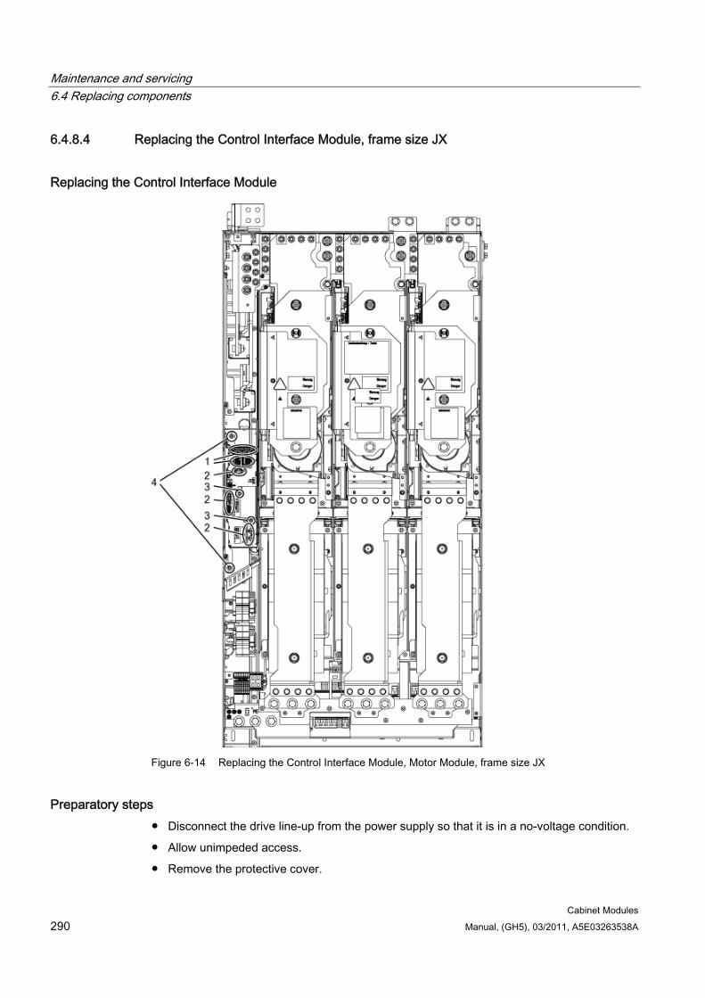
Maintenance and servicing 6.4 Replacing components
Cabinet Modules 290 Manual, (GH5), 03/2011, A5E03263538A
6.4.8.4 Replacing the Control Interface Module, frame size JX
Replacing the Control Interface Module
Figure 6-14 Replacing the Control Interface Module, Motor Module, frame size JX
Preparatory steps Disconnect the drive line-up from the power supply so that it is in a no-voltage condition.
Allow unimpeded access.
Remove the protective cover.

Maintenance and servicing 6.4 Replacing components
Cabinet Modules Manual, (GH5), 03/2011, A5E03263538A 291
Removal steps The removal steps are numbered in accordance with the figure.
1. Disconnect the plug-in connections for the fiber optic cables and signal cables (5 connectors).
2. Remove the DRIVE-CLiQ cables and connections on -X41 / -X42 / -X46 (6 plugs).
3. Take out the retaining screws for the IPD card (2 screws) and remove the IPD card from plug -X45 on the Control Interface Module.
4. Remove the retaining screws for the Control Interface Module (2 screws).
When removing the Control Interface Module, you have to disconnect 5 further plugs one after the other (2 at the top, 3 below).
CAUTION When withdrawing it, ensure that you do not damage any signal cables.
Installation steps Installing is the same as removing, however in the reverse order.
CAUTION The tightening torques specified in the table "Tightening torques for connecting current-conducting parts" must be observed.
Carefully establish the plug connections and then ensure that they are secure.
The screw connections for the protective covers may only be tightened by hand.
The fiber optic cable plugs must be remounted at their original slot. Fiber optic cables and sockets are accordingly labeled for correct assignment (U11, U21, U31).
Note
It is only possible to connect identical power units in parallel if both power units have the same hardware version. Mixed operation between a power unit with Control Interface Module and a power unit with Control Interface Board is not possible.
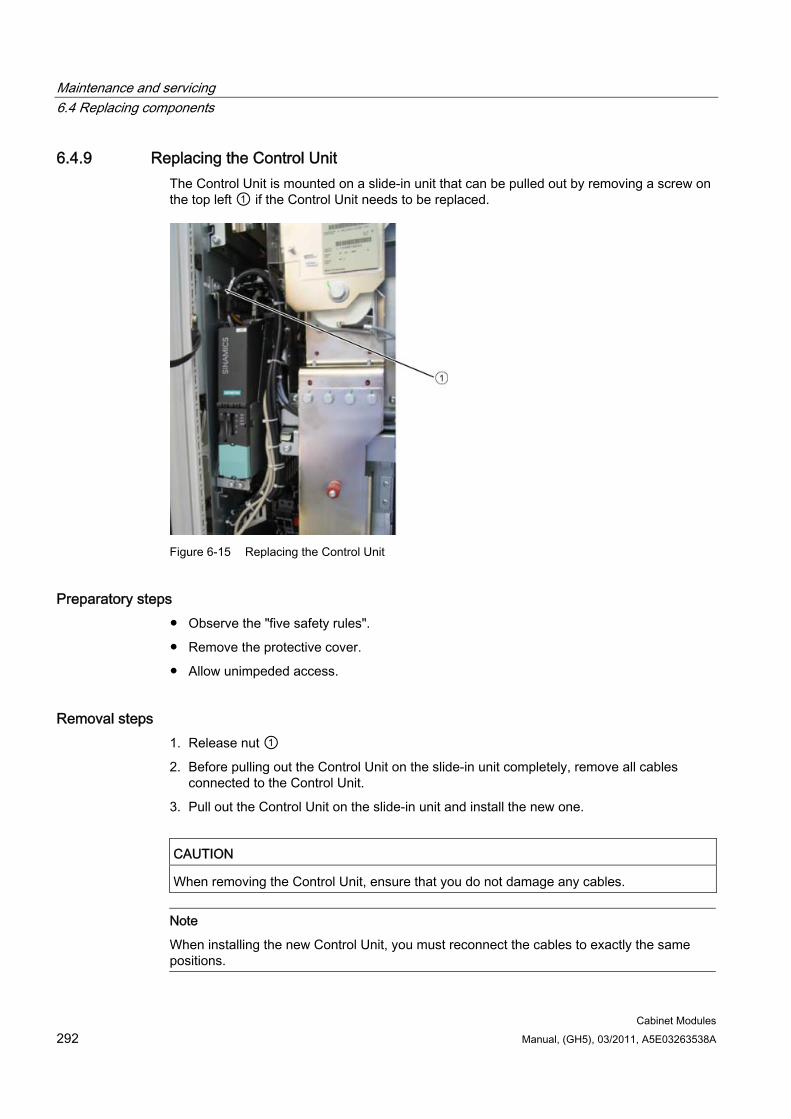
Maintenance and servicing 6.4 Replacing components
Cabinet Modules 292 Manual, (GH5), 03/2011, A5E03263538A
6.4.9 Replacing the Control Unit The Control Unit is mounted on a slide-in unit that can be pulled out by removing a screw on the top left ① if the Control Unit needs to be replaced.
Figure 6-15 Replacing the Control Unit
Preparatory steps Observe the "five safety rules".
Remove the protective cover.
Allow unimpeded access.
Removal steps 1. Release nut ①
2. Before pulling out the Control Unit on the slide-in unit completely, remove all cables connected to the Control Unit.
3. Pull out the Control Unit on the slide-in unit and install the new one.
CAUTION When removing the Control Unit, ensure that you do not damage any cables.
Note
When installing the new Control Unit, you must reconnect the cables to exactly the same positions.
Maintenance and servicing 6.4 Replacing components
Cabinet Modules Manual, (GH5), 03/2011, A5E03263538A 293
6.4.10 Replacing the fans
6.4.10.1 Replacing the fan, Booksize Cabinet Kit
Preparatory steps Observe the "five safety rules".
Remove the protective cover.
Allow unimpeded access.
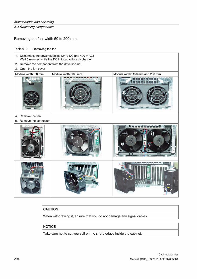
Maintenance and servicing 6.4 Replacing components
Cabinet Modules 294 Manual, (GH5), 03/2011, A5E03263538A
Removing the fan, width 50 to 200 mm
Table 6- 2 Removing the fan
1. Disconnect the power supplies (24 V DC and 400 V AC) Wait 5 minutes while the DC link capacitors discharge!
2. Remove the component from the drive line-up. 3. Open the fan cover
Module width: 50 mm Module width: 100 mm Module width: 150 mm and 200 mm
4. Remove the fan. 5. Remove the connector.
CAUTION When withdrawing it, ensure that you do not damage any signal cables.
NOTICE Take care not to cut yourself on the sharp edges inside the cabinet.

Maintenance and servicing 6.4 Replacing components
Cabinet Modules Manual, (GH5), 03/2011, A5E03263538A 295
Installation steps for the fan, width 50 to 200 mm 1. Before installing the fan, check the air flow direction
(the arrow on the fan must point towards the cooling fins).
2. Insert the connector until it fully engages.
3. Insert the fan until it latches into place. Do not pinch the connecting cables.
4. Close the fan cover.
CAUTION
The tightening torques specified in the table "Tightening torques for connecting current-conducting parts" must be observed.
The screw connections for the protective covers may only be tightened by hand.
Removing the fan, width 300 mm
Figure 6-16 Removing the 300mm fan
1. Undo the M6 / 6 Nm screws (1)
2. Disconnect the power supply for the fan (2)
3. The fan can now be removed
Maintenance and servicing 6.4 Replacing components
Cabinet Modules 296 Manual, (GH5), 03/2011, A5E03263538A
CAUTION
When withdrawing it, ensure that you do not damage any signal cables.
NOTICE
Take care not to cut yourself on the sharp edges inside the cabinet.
Installation steps for the fan, width 300 mm Installing is the same as removing, however in the reverse order.
CAUTION The tightening torques specified in the table "Tightening torques for connecting current-conducting parts" must be observed.
The screw connections for the protective covers may only be tightened by hand.
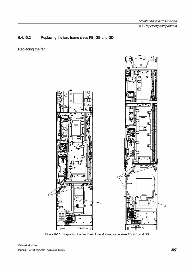
Maintenance and servicing 6.4 Replacing components
Cabinet Modules Manual, (GH5), 03/2011, A5E03263538A 297
6.4.10.2 Replacing the fan, frame sizes FB, GB and GD
Replacing the fan
Figure 6-17 Replacing the fan, Basic Line Module, frame sizes FB, GB, and GD
Maintenance and servicing 6.4 Replacing components
Cabinet Modules 298 Manual, (GH5), 03/2011, A5E03263538A
Description The average service life of the device fans is approximately 50,000 hours. In practice, however, the service life depends on other variables (e.g. ambient temperature, degree of cabinet protection, etc.) and, therefore, may deviate from this value.
The fans must be replaced in good time to ensure the availability of the Cabinet Module.
Preparatory steps Observe the "five safety rules".
Remove the protective cover.
Allow unimpeded access.
Removal steps The removal steps are numbered in accordance with the figure above.
1. Remove the retaining screws for the fan (2 screws for frame size FB; 3 screws for frame sizes GB and GD).
2. Disconnect the supply cables (1 x "L", 1 x "N").
You can now carefully remove the fan.
CAUTION When removing the fan, ensure that you do not damage any signal cables.
NOTICE Take care not to cut yourself on the sharp edges inside the cabinet.
Installation steps For installation, carry out the above steps in reverse order.
CAUTION The tightening torques specified in the table "Tightening torques for connecting current-conducting parts" must be observed.
The screwed connections for the protective covers must only be tightened by hand.
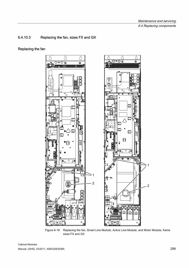
Maintenance and servicing 6.4 Replacing components
Cabinet Modules Manual, (GH5), 03/2011, A5E03263538A 299
6.4.10.3 Replacing the fan, sizes FX and GX
Replacing the fan
Figure 6-18 Replacing the fan, Smart Line Module, Active Line Module, and Motor Module, frame
sizes FX and GX
Maintenance and servicing 6.4 Replacing components
Cabinet Modules 300 Manual, (GH5), 03/2011, A5E03263538A
Description The average service life of the device fans is approximately 50,000 hours. In practice, however, the service life depends on other variables (e.g. ambient temperature, degree of cabinet protection, etc.) and, therefore, may deviate from this value.
The fans must be replaced in good time to ensure the availability of the Cabinet Module.
Preparatory steps Observe the "five safety rules".
Remove the protective cover.
Allow unimpeded access.
Removal steps The removal steps are numbered in accordance with the figure above.
1. Remove the retaining screws for the fan (2 screws for frame size FX; 3 screws for frame size GX)
2. Disconnect the supply cables (1 x "L", 1 x "N").
You can now carefully remove the fan.
CAUTION When removing the fan, ensure that you do not damage any signal cables.
NOTICE Take care not to cut yourself on the sharp edges inside the cabinet.
Installation steps For installation, carry out the above steps in reverse order.
CAUTION The tightening torques specified in the table "Tightening torques for connecting current-conducting parts" must be observed.
The screwed connections for the protective covers must only be tightened by hand.
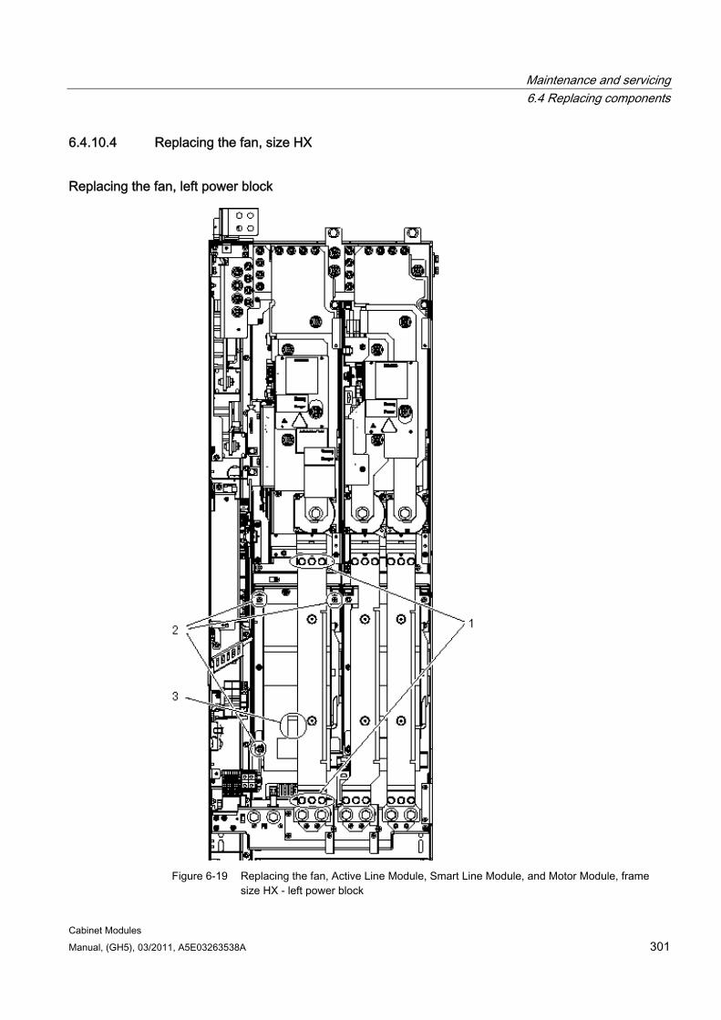
Maintenance and servicing 6.4 Replacing components
Cabinet Modules Manual, (GH5), 03/2011, A5E03263538A 301
6.4.10.4 Replacing the fan, size HX
Replacing the fan, left power block
Figure 6-19 Replacing the fan, Active Line Module, Smart Line Module, and Motor Module, frame
size HX - left power block
Maintenance and servicing 6.4 Replacing components
Cabinet Modules 302 Manual, (GH5), 03/2011, A5E03263538A
Description The average service life of the device fans is approximately 50,000 hours. In practice, however, the service life depends on other variables (e.g. ambient temperature, degree of cabinet protection, etc.) and, therefore, may deviate from this value.
The fans must be replaced in good time to ensure the availability of the Cabinet Module.
Preparatory steps Observe the "five safety rules".
Remove the protective cover.
Allow unimpeded access.
Removal steps The removal steps are numbered in accordance with the figure above.
1. Remove the busbar (6 screws).
2. Remove the retaining screws for the fan (3 screws).
3. Disconnect the supply cables (1 x "L", 1 x "N").
You can now carefully remove the fan.
CAUTION When withdrawing it, ensure that you do not damage any signal cables.
NOTICE Take care not to cut yourself on the sharp edges inside the cabinet.
Installation steps Installing is the same as removing, however in the reverse order.
CAUTION The tightening torques specified in the table "Tightening torques for connecting current-conducting parts" must be observed.
The screw connections for the protective covers may only be tightened by hand.
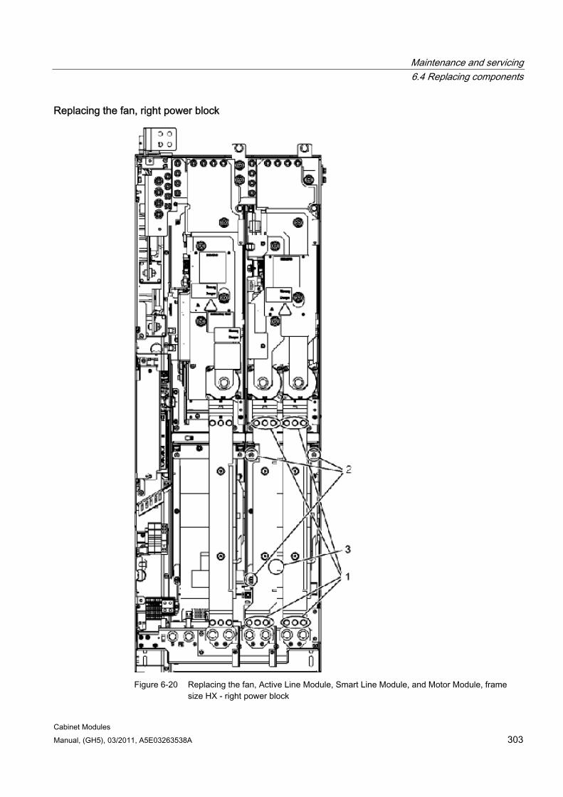
Maintenance and servicing 6.4 Replacing components
Cabinet Modules Manual, (GH5), 03/2011, A5E03263538A 303
Replacing the fan, right power block
Figure 6-20 Replacing the fan, Active Line Module, Smart Line Module, and Motor Module, frame
size HX - right power block

Maintenance and servicing 6.4 Replacing components
Cabinet Modules 304 Manual, (GH5), 03/2011, A5E03263538A
Description The average service life of the device fans is approximately 50,000 hours. In practice, however, the service life depends on other variables (e.g. ambient temperature, degree of cabinet protection, etc.) and, therefore, may deviate from this value.
The fans must be replaced in good time to ensure the availability of the Cabinet Module.
Preparatory steps Observe the "five safety rules".
Remove the protective cover.
Allow unimpeded access.
Removal steps The removal steps are numbered in accordance with the figure above.
1. Remove the busbars (12 screws).
2. Remove the retaining screws for the fan (3 screws).
3. Disconnect the supply cables (1 x "L", 1 x "N").
You can now carefully remove the fan.
CAUTION When withdrawing it, ensure that you do not damage any signal cables.
NOTICE Take care not to cut yourself on the sharp edges inside the cabinet.
Installation steps Installing is the same as removing, however in the reverse order.
CAUTION The tightening torques specified in the table "Tightening torques for connecting current-conducting parts" must be observed.
The screw connections for the protective covers may only be tightened by hand.
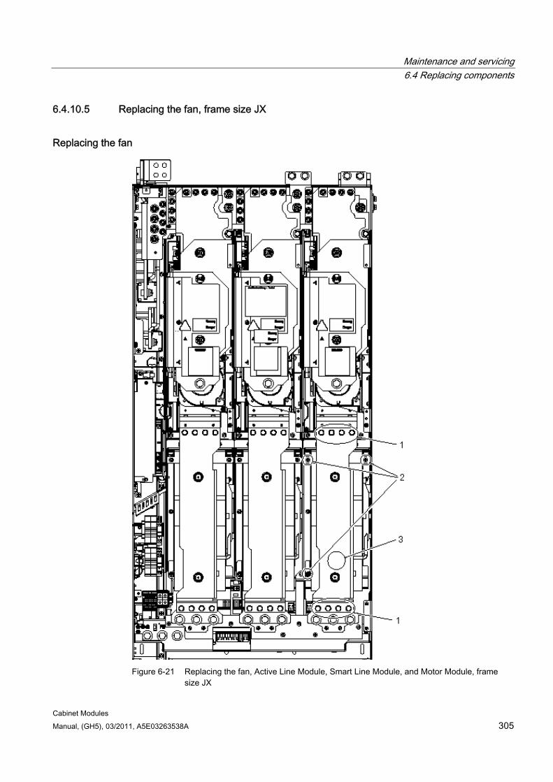
Maintenance and servicing 6.4 Replacing components
Cabinet Modules Manual, (GH5), 03/2011, A5E03263538A 305
6.4.10.5 Replacing the fan, frame size JX
Replacing the fan
Figure 6-21 Replacing the fan, Active Line Module, Smart Line Module, and Motor Module, frame
size JX
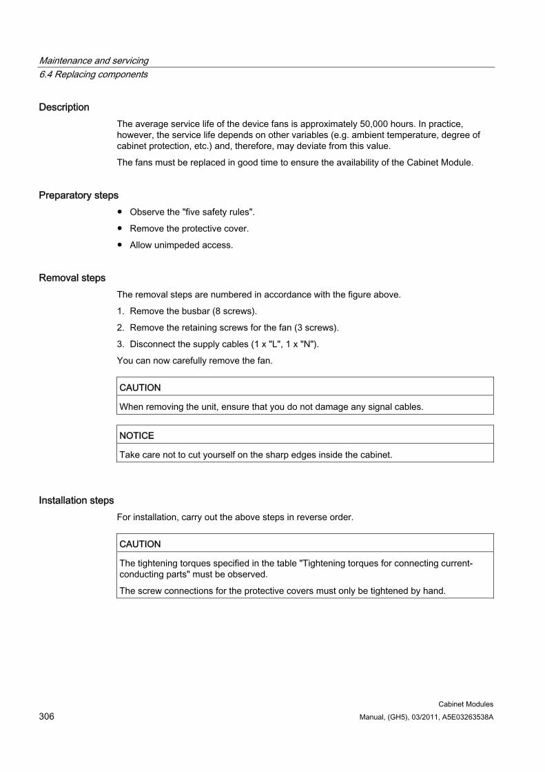
Maintenance and servicing 6.4 Replacing components
Cabinet Modules 306 Manual, (GH5), 03/2011, A5E03263538A
Description The average service life of the device fans is approximately 50,000 hours. In practice, however, the service life depends on other variables (e.g. ambient temperature, degree of cabinet protection, etc.) and, therefore, may deviate from this value.
The fans must be replaced in good time to ensure the availability of the Cabinet Module.
Preparatory steps Observe the "five safety rules".
Remove the protective cover.
Allow unimpeded access.
Removal steps The removal steps are numbered in accordance with the figure above.
1. Remove the busbar (8 screws).
2. Remove the retaining screws for the fan (3 screws).
3. Disconnect the supply cables (1 x "L", 1 x "N").
You can now carefully remove the fan.
CAUTION When removing the unit, ensure that you do not damage any signal cables.
NOTICE Take care not to cut yourself on the sharp edges inside the cabinet.
Installation steps For installation, carry out the above steps in reverse order.
CAUTION The tightening torques specified in the table "Tightening torques for connecting current-conducting parts" must be observed.
The screw connections for the protective covers must only be tightened by hand.
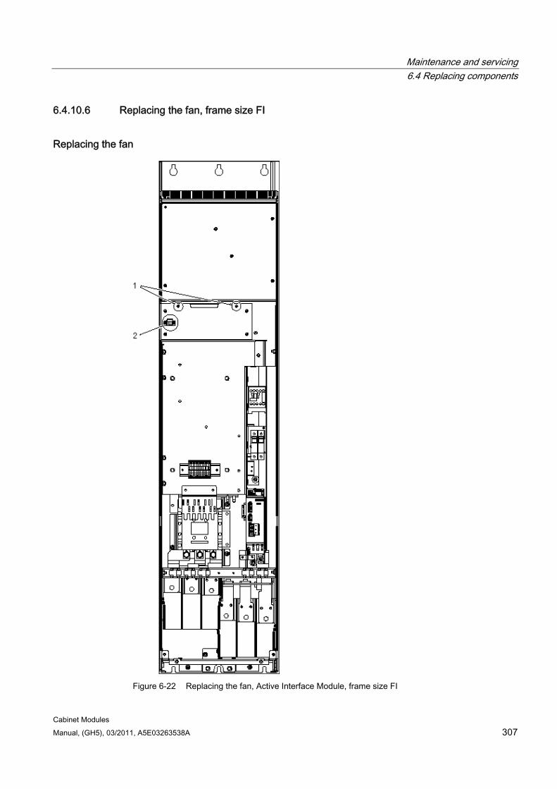
Maintenance and servicing 6.4 Replacing components
Cabinet Modules Manual, (GH5), 03/2011, A5E03263538A 307
6.4.10.6 Replacing the fan, frame size FI
Replacing the fan
Figure 6-22 Replacing the fan, Active Interface Module, frame size FI

Maintenance and servicing 6.4 Replacing components
Cabinet Modules 308 Manual, (GH5), 03/2011, A5E03263538A
Description The average service life of the device fans is approximately 50,000 hours. In practice, however, the service life depends on other variables (e.g. ambient temperature, degree of cabinet protection, etc.) and, therefore, may deviate from this value.
The fans must be replaced in good time to ensure the availability of the Cabinet Module.
Preparatory steps Observe the "five safety rules".
Remove the protective cover.
Allow unimpeded access.
Removal steps The removal steps are numbered in accordance with the figure above.
1. Remove the retaining screws for the fan unit (2 screws).
2. Unplug connector -X630.
You can now carefully remove the fan.
CAUTION When removing the fan, ensure that you do not damage any signal cables.
NOTICE Take care not to cut yourself on the sharp edges inside the cabinet.
Installation steps For installation, carry out the above steps in reverse order.
CAUTION The tightening torques specified in the table "Tightening torques for connecting current-conducting parts" must be observed.
Carefully establish the plug connections and ensure that they are secure.
The screwed connections for the protective covers must only be tightened by hand.
Maintenance and servicing 6.4 Replacing components
Cabinet Modules Manual, (GH5), 03/2011, A5E03263538A 309
6.4.10.7 Replacing the fan, frame size GI
Replacing the fan
Figure 6-23 Replacing the fan, Active Interface Module, frame size GI
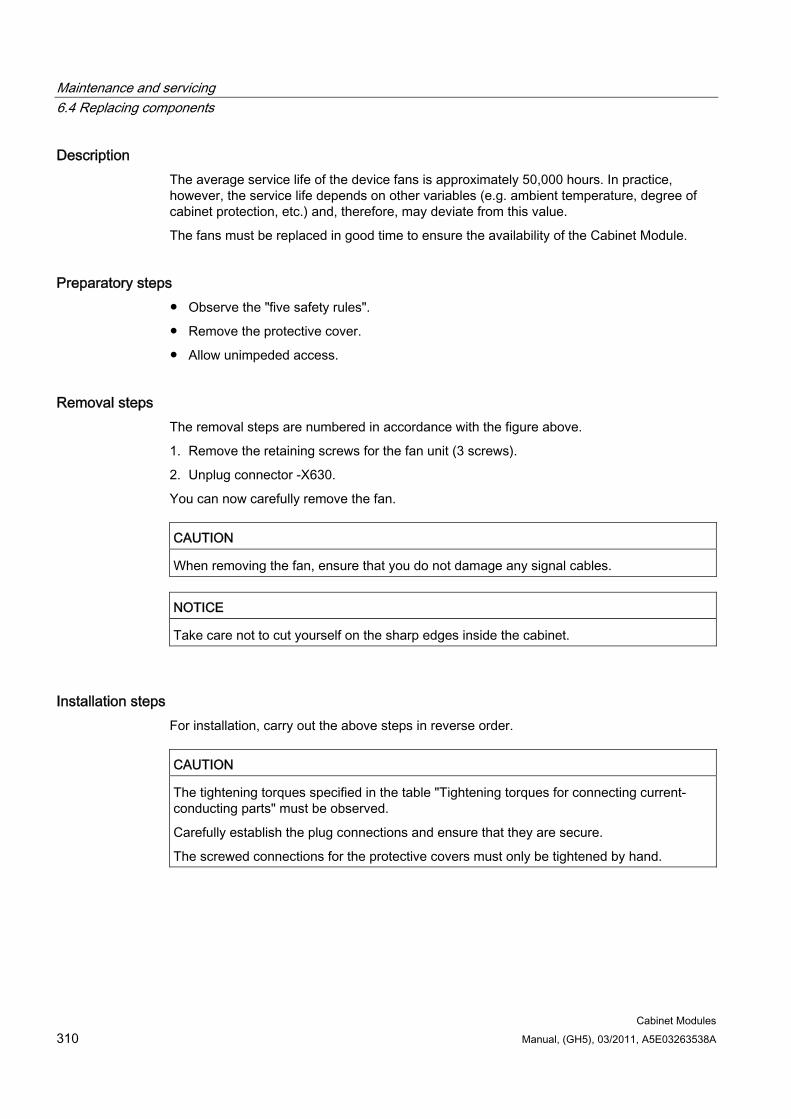
Maintenance and servicing 6.4 Replacing components
Cabinet Modules 310 Manual, (GH5), 03/2011, A5E03263538A
Description The average service life of the device fans is approximately 50,000 hours. In practice, however, the service life depends on other variables (e.g. ambient temperature, degree of cabinet protection, etc.) and, therefore, may deviate from this value.
The fans must be replaced in good time to ensure the availability of the Cabinet Module.
Preparatory steps Observe the "five safety rules".
Remove the protective cover.
Allow unimpeded access.
Removal steps The removal steps are numbered in accordance with the figure above.
1. Remove the retaining screws for the fan unit (3 screws).
2. Unplug connector -X630.
You can now carefully remove the fan.
CAUTION When removing the fan, ensure that you do not damage any signal cables.
NOTICE Take care not to cut yourself on the sharp edges inside the cabinet.
Installation steps For installation, carry out the above steps in reverse order.
CAUTION The tightening torques specified in the table "Tightening torques for connecting current-conducting parts" must be observed.
Carefully establish the plug connections and ensure that they are secure.
The screwed connections for the protective covers must only be tightened by hand.
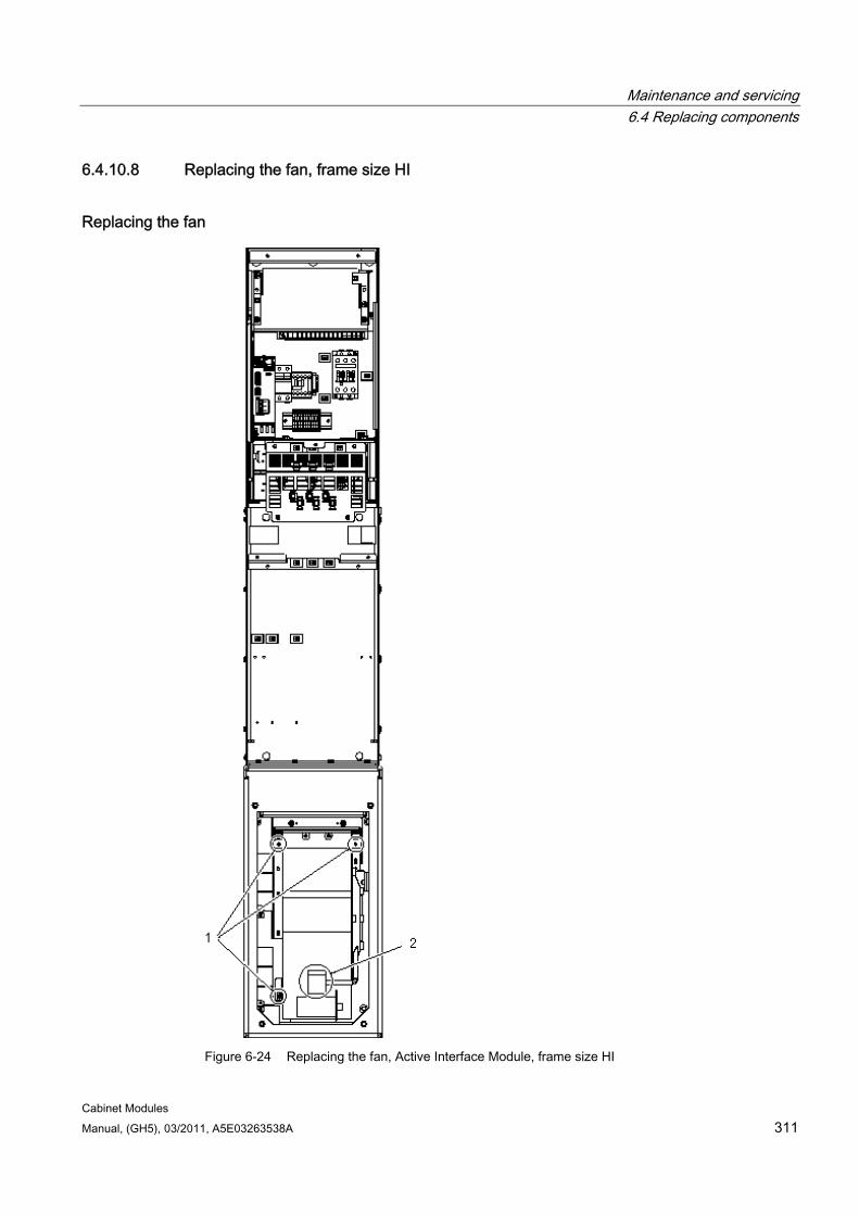
Maintenance and servicing 6.4 Replacing components
Cabinet Modules Manual, (GH5), 03/2011, A5E03263538A 311
6.4.10.8 Replacing the fan, frame size HI
Replacing the fan
Figure 6-24 Replacing the fan, Active Interface Module, frame size HI
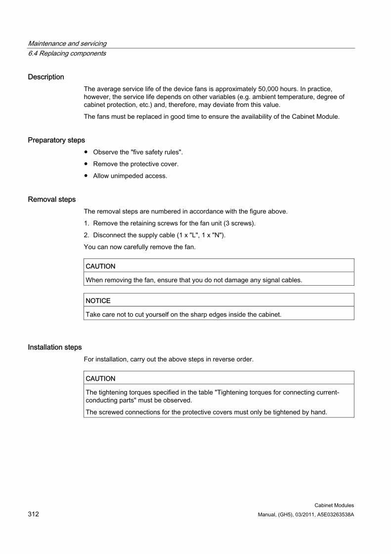
Maintenance and servicing 6.4 Replacing components
Cabinet Modules 312 Manual, (GH5), 03/2011, A5E03263538A
Description The average service life of the device fans is approximately 50,000 hours. In practice, however, the service life depends on other variables (e.g. ambient temperature, degree of cabinet protection, etc.) and, therefore, may deviate from this value.
The fans must be replaced in good time to ensure the availability of the Cabinet Module.
Preparatory steps Observe the "five safety rules".
Remove the protective cover.
Allow unimpeded access.
Removal steps The removal steps are numbered in accordance with the figure above.
1. Remove the retaining screws for the fan unit (3 screws).
2. Disconnect the supply cable (1 x "L", 1 x "N").
You can now carefully remove the fan.
CAUTION When removing the fan, ensure that you do not damage any signal cables.
NOTICE Take care not to cut yourself on the sharp edges inside the cabinet.
Installation steps For installation, carry out the above steps in reverse order.
CAUTION The tightening torques specified in the table "Tightening torques for connecting current-conducting parts" must be observed.
The screwed connections for the protective covers must only be tightened by hand.
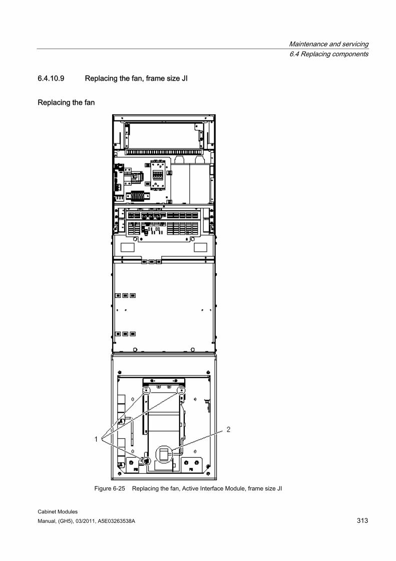
Maintenance and servicing 6.4 Replacing components
Cabinet Modules Manual, (GH5), 03/2011, A5E03263538A 313
6.4.10.9 Replacing the fan, frame size JI
Replacing the fan
Figure 6-25 Replacing the fan, Active Interface Module, frame size JI

Maintenance and servicing 6.4 Replacing components
Cabinet Modules 314 Manual, (GH5), 03/2011, A5E03263538A
Description The average service life of the device fans is approximately 50,000 hours. In practice, however, the service life depends on other variables (e.g. ambient temperature, degree of cabinet protection, etc.) and, therefore, may deviate from this value.
The fans must be replaced in good time to ensure the availability of the Cabinet Module.
Preparatory steps Observe the "five safety rules".
Remove the protective cover.
Allow unimpeded access.
Removal steps The removal steps are numbered in accordance with the figure above.
1. Remove the retaining screws for the fan unit (3 screws).
2. Disconnect the supply cable (1 x "L", 1 x "N").
You can now carefully remove the fan.
CAUTION When removing the fan, ensure that you do not damage any signal cables.
NOTICE Take care not to cut yourself on the sharp edges inside the cabinet.
Installation steps For installation, carry out the above steps in reverse order.
CAUTION The tightening torques specified in the table "Tightening torques for connecting current-conducting parts" must be observed.
The screwed connections for the protective covers must only be tightened by hand.
Maintenance and servicing 6.4 Replacing components
Cabinet Modules Manual, (GH5), 03/2011, A5E03263538A 315
6.4.11 Replacing the fuses
Replacement fuses You can find the order numbers for replacing auxiliary power supply fuses that have blown in the spare parts list.
WARNING When replacing fuses, you must take the following points into account: 1. Observe the "five safety rules". 2. Disconnect the cabinet from the power supply (do not forget the external power
supplies). 3. Then rectify the cause of the fault. 4. Install a new fuse once the cause of the fault has been rectified.
6.4.11.1 Replacing the fuses for the auxiliary power supply
Replacement fuses You can find the order numbers for replacing auxiliary power supply fuses that have blown in the spare parts list.
WARNING When replacing fuses, you must take the following points into account: 1. Observe the "five safety rules". 2. Disconnect the cabinet from the power supply (do not forget the external power
supplies). 3. Then rectify the cause of the fault. 4. Install a new fuse once the cause of the fault has been rectified.
Maintenance and servicing 6.4 Replacing components
Cabinet Modules 316 Manual, (GH5), 03/2011, A5E03263538A
6.4.11.2 Replacing the fuses (F71 to F73) in the Line Connection Module
Preparatory steps Observe the "five safety rules".
Disconnect the cabinet from the power supply (do not forget the external power supplies).
Have the fuse grip ready.
Removal and installation procedures
Note
On Line Connection Modules with a rated current of < 800 A, the fuses are freely accessible and can be replaced once the fault cause has been eliminated.
Note
On Line Connection Modules with a rated current of between 800 and 1600 A, the removal procedures described below must be carefully followed to replace the fuses.
1. Open the cabinet.
2. Take the top screws out of the support plate underneath the fuses. Loosen the bottom screws slightly. The support plate can then be pushed downwards.
3. Attach the fuse grip to the fuse.
4. Remove the defective fuse.
5. Press the yellow button on the fuse grip to release the defective fuse from it.
6. Attach the new fuse onto the grip.
7. Place the new fuse in the fuse holder in the cabinet.
8. Press the yellow button on the fuse grip to release the new fuse from it.
9. Attach the support plates underneath the fuses again.
10. Close the cabinet.
Note
If necessary, the fuse grip can be ordered from Siemens.
Maintenance and servicing 6.4 Replacing components
Cabinet Modules Manual, (GH5), 03/2011, A5E03263538A 317
6.4.11.3 Replacing fuses in the fuse switch disconnector for Booksize Cabinet Kit
Preparatory steps Observe the "five safety rules".
Disconnect the cabinet from the power supply (do not forget the external power supplies).
Replacing 1. If option L37 is present, switch off the relevant DC interface in the door.
2. Open the door.
3. Open the fuse switch disconnector.
4. Remove the fuse link.
5. Replace the defective fuses.
6. Complete the procedure by carrying out the above actions in reverse order.
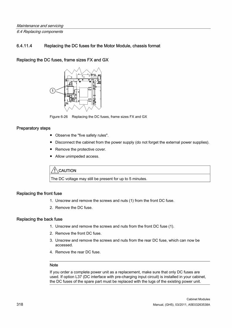
Maintenance and servicing 6.4 Replacing components
Cabinet Modules 318 Manual, (GH5), 03/2011, A5E03263538A
6.4.11.4 Replacing the DC fuses for the Motor Module, chassis format
Replacing the DC fuses, frame sizes FX and GX
Figure 6-26 Replacing the DC fuses, frame sizes FX and GX
Preparatory steps Observe the "five safety rules".
Disconnect the cabinet from the power supply (do not forget the external power supplies).
Remove the protective cover.
Allow unimpeded access.
CAUTION The DC voltage may still be present for up to 5 minutes.
Replacing the front fuse 1. Unscrew and remove the screws and nuts (1) from the front DC fuse.
2. Remove the DC fuse.
Replacing the back fuse 1. Unscrew and remove the screws and nuts from the front DC fuse (1).
2. Remove the front DC fuse.
3. Unscrew and remove the screws and nuts from the rear DC fuse, which can now be accessed.
4. Remove the rear DC fuse.
Note
If you order a complete power unit as a replacement, make sure that only DC fuses are used. If option L37 (DC interface with pre-charging input circuit) is installed in your cabinet, the DC fuses of the spare part must be replaced with the lugs of the existing power unit.
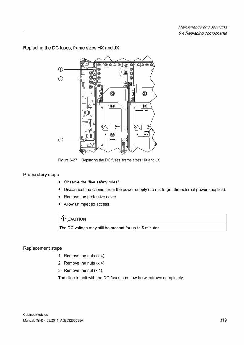
Maintenance and servicing 6.4 Replacing components
Cabinet Modules Manual, (GH5), 03/2011, A5E03263538A 319
Replacing the DC fuses, frame sizes HX and JX
Figure 6-27 Replacing the DC fuses, frame sizes HX and JX
Preparatory steps Observe the "five safety rules".
Disconnect the cabinet from the power supply (do not forget the external power supplies).
Remove the protective cover.
Allow unimpeded access.
CAUTION The DC voltage may still be present for up to 5 minutes.
Replacement steps 1. Remove the nuts (x 4).
2. Remove the nuts (x 4).
3. Remove the nut (x 1).
The slide-in unit with the DC fuses can now be withdrawn completely.
Maintenance and servicing 6.4 Replacing components
Cabinet Modules 320 Manual, (GH5), 03/2011, A5E03263538A
Note
The slide-in unit with the DC fuses must be pulled out completely and placed down so that it cannot topple over.
The screws and nuts must now be unscrewed and removed from the DC fuses as necessary in order to change the relevant DC fuses.
Note
Frame size HX contains two DC fuses and frame size JXcontains four DC fuses.
If you order a complete power unit as a replacement, make sure that only DC fuses are used. If option L37 (DC interface with pre-charging input circuit) is installed in your cabinet, the DC fuses of the spare part must be replaced with the lugs of the existing power unit.
6.4.11.5 Replacing the encapsulated fuses
Preparatory steps Observe the "five safety rules".
Disconnect the cabinet from the power supply (do not forget the external power supplies).
Replacement steps 1. Open the cabinet.
2. Open the fuse holder (push the flap down/up).
3. Remove the defective fuse.
4. Insert the replacement fuse.
5. Close the fuse holder (push the flap up/down).
6. Close the cabinet.
Maintenance and servicing 6.4 Replacing components
Cabinet Modules Manual, (GH5), 03/2011, A5E03263538A 321
6.4.11.6 Replacing the LV HRC fuses
Preparatory steps Observe the "five safety rules".
Disconnect the cabinet from the power supply (do not forget the external power supplies).
Have the fuse grip ready.
Replacement steps 1. Open the cabinet.
2. Attach the fuse grip to the fuse.
3. Remove the defective fuse.
4. Press the yellow button on the fuse grip to release the defective fuse from it.
5. Attach the new fuse onto the grip.
6. Place the new fuse in the fuse holder in the cabinet.
7. Press the yellow button on the fuse grip to release the new fuse from it.
8. Close the cabinet.
Note
If necessary, the fuse grip can be ordered from Siemens.
Maintenance and servicing 6.4 Replacing components
Cabinet Modules 322 Manual, (GH5), 03/2011, A5E03263538A
6.4.12 Replacing the DC interface (option L37)
Preparatory steps Observe the "five safety rules".
Disconnect the cabinet from the power supply (do not forget the external power supplies).
Allow unimpeded access (Motor Module); (if no Control Unit is present, the plate can simply be unscrewed and turned to one side).
Removal 1. Switch off the relevant DC interface in the door.
2. Open the cabinet.
3. Open the fuse switch disconnector and remove the fuse link.
4. Remove the infeed cable to the Motor Module at the contactor.
5. Detach the motor plug or disconnect and insulate the motor cables.
6. Open the cover for the Motor Module.
7. Remove the 24 V DC connector and insulate the contact surfaces so that they cannot be touched.
8. Remove the cable (2 -T1) at the contactor.
9. Remove the screws on the DC rectifier adapter.
10. Remove the connector (-X37).
11. Remove the cable ties on the cable to the DC rectifier adapter.
12. Remove the lower screws (up to 3) on the support plate for the pre-charger.
13. Remove the upper screws (up to 3) on the support plate for the pre-charger.
CAUTION
The pre-charger is only secured by the upper and lower screws, which means that it must be supported when you remove the final screws.
14. Carefully remove the support plate for the pre-charger and the DC rectifier adapter.
Installation Installing is the same as removing, however in the reverse order.
Note
Use new cable ties to secure the cable to the DC rectifier adapter.
Maintenance and servicing 6.4 Replacing components
Cabinet Modules Manual, (GH5), 03/2011, A5E03263538A 323
6.4.13 Replacing the pre-charging resistors of the DC interface (option L37)
Preparatory steps Observe the "five safety rules".
Disconnect the cabinet from the power supply (do not forget the external power supplies).
Removal 1. Remove the DC interface (see the section titled "Replacing the DC interface for Booksize
Cabinet Kit").
2. Remove the fastening screws for the pre-charging resistors.
3. Remove the resistors.
Installation 1. Insert the new resistors.
2. Tighten the fastening screws of the pre-charging resistors.
3. Re-install the DC interface.
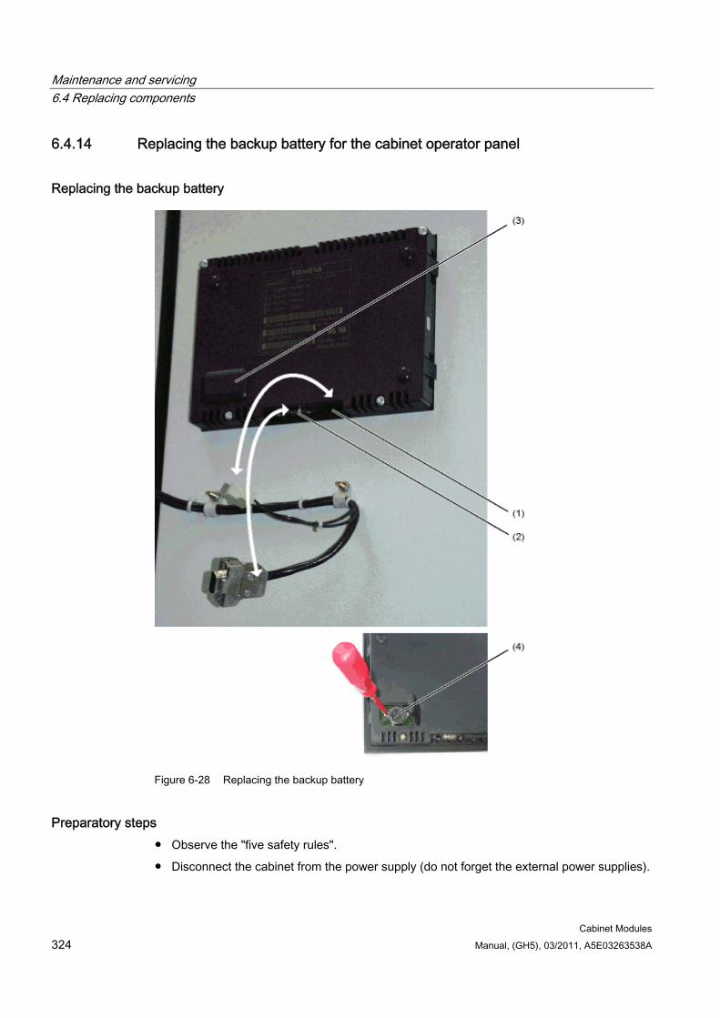
Maintenance and servicing 6.4 Replacing components
Cabinet Modules 324 Manual, (GH5), 03/2011, A5E03263538A
6.4.14 Replacing the backup battery for the cabinet operator panel
Replacing the backup battery
Figure 6-28 Replacing the backup battery
Preparatory steps Observe the "five safety rules".
Disconnect the cabinet from the power supply (do not forget the external power supplies).
Maintenance and servicing 6.4 Replacing components
Cabinet Modules Manual, (GH5), 03/2011, A5E03263538A 325
Replacing 1. Disconnect the 24 V DC power-supply cable.
2. Disconnect the communication cable on the operator panel.
3. Open the cover of the battery compartment.
4. Remove the old battery.
5. Insert the new battery.
6. Complete the procedure by carrying out the above actions in reverse order.
Table 6- 3 Technical data for the backup battery
Type CR2032 3 V lithium battery Vendor Maxell, Sony, Panasonic Rated capacity 220 mAh Maximum permissible charging current 10 mA (restricted to < 2 mA in operator panel) Self-discharge at 20 °C 1 %/year Service life (in backup mode) > 1 year at 70 °C > 1.5 years at 20 °C
NOTICE You must replace the battery within a period of one minute.
If the process takes longer than a minute, this can result in data being lost.
The battery must be disposed of in accordance with the applicable country-specific guidelines and regulations.
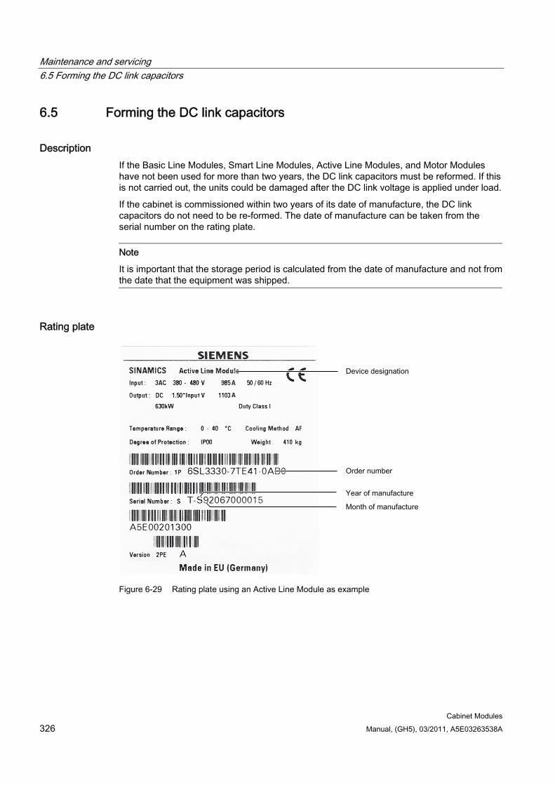
Maintenance and servicing 6.5 Forming the DC link capacitors
Cabinet Modules 326 Manual, (GH5), 03/2011, A5E03263538A
6.5 Forming the DC link capacitors
Description If the Basic Line Modules, Smart Line Modules, Active Line Modules, and Motor Modules have not been used for more than two years, the DC link capacitors must be reformed. If this is not carried out, the units could be damaged after the DC link voltage is applied under load.
If the cabinet is commissioned within two years of its date of manufacture, the DC link capacitors do not need to be re-formed. The date of manufacture can be taken from the serial number on the rating plate.
Note
It is important that the storage period is calculated from the date of manufacture and not from the date that the equipment was shipped.
Rating plate
Figure 6-29 Rating plate using an Active Line Module as example
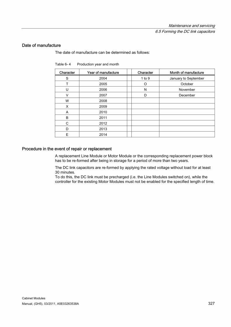
Maintenance and servicing 6.5 Forming the DC link capacitors
Cabinet Modules Manual, (GH5), 03/2011, A5E03263538A 327
Date of manufacture The date of manufacture can be determined as follows:
Table 6- 4 Production year and month
Character Year of manufacture Character Month of manufacture S 2004 1 to 9 January to September T 2005 O October U 2006 N November V 2007 D December W 2008 X 2009 A 2010 B 2011 C 2012 D 2013 E 2014
Procedure in the event of repair or replacement A replacement Line Module or Motor Module or the corresponding replacement power block has to be re-formed after being in storage for a period of more than two years.
The DC link capacitors are re-formed by applying the rated voltage without load for at least 30 minutes. To do this, the DC link must be precharged (i.e. the Line Modules switched on), while the controller for the existing Motor Modules must not be enabled for the specified length of time.
Maintenance and servicing 6.5 Forming the DC link capacitors
Cabinet Modules 328 Manual, (GH5), 03/2011, A5E03263538A
Procedure for re-forming outside the drive line-up Replacement power units which have to be held ready for immediate use in the event of repair or replacement can also be re-formed individually and outside the drive line-up.
For this, the equipment must be connected to the forming circuits described in the following.
Components for the forming circuit (recommendation)
1 fuse switch 3-phase 400 V / 10 A or 690 V / 10 A
3 incandescent lamps 230 V / 100 W for a line voltage of 380 to 480 V 3 AC. Alternatively, use 3 resistors of 1 kΩ / 100 W each (e.g. GWK150J1001KLX000 from Vishay) instead of the incandescent lamps.
6 incandescent lamps 230 V / 100 W for a line voltage of 500 to 690 V 3 AC, where 2 incandescent lamps must be connected in series in each supply phase. Alternatively, use 3 resistors of 1 kΩ / 160 W each (e.g. GWK200J1001KLX000 from Vishay) instead of the incandescent lamps.
Various small components, such as lamp sockets, cable 1.5 mm2, etc.
CAUTION
For a line voltage of 500 to 690 V 3 AC, the two lamp sockets connected in series must be insulated and protected from touch, because the insulation of the sockets is not designed for this high voltage.
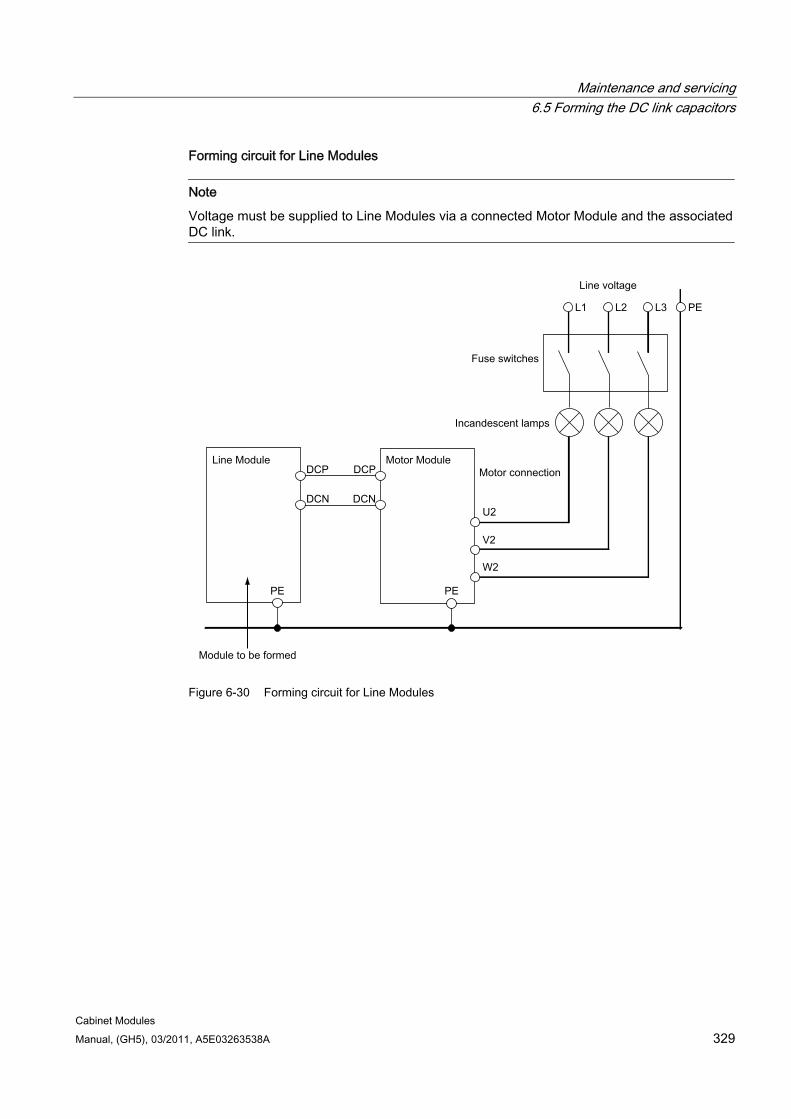
Maintenance and servicing 6.5 Forming the DC link capacitors
Cabinet Modules Manual, (GH5), 03/2011, A5E03263538A 329
Forming circuit for Line Modules
Note
Voltage must be supplied to Line Modules via a connected Motor Module and the associated DC link.
Figure 6-30 Forming circuit for Line Modules
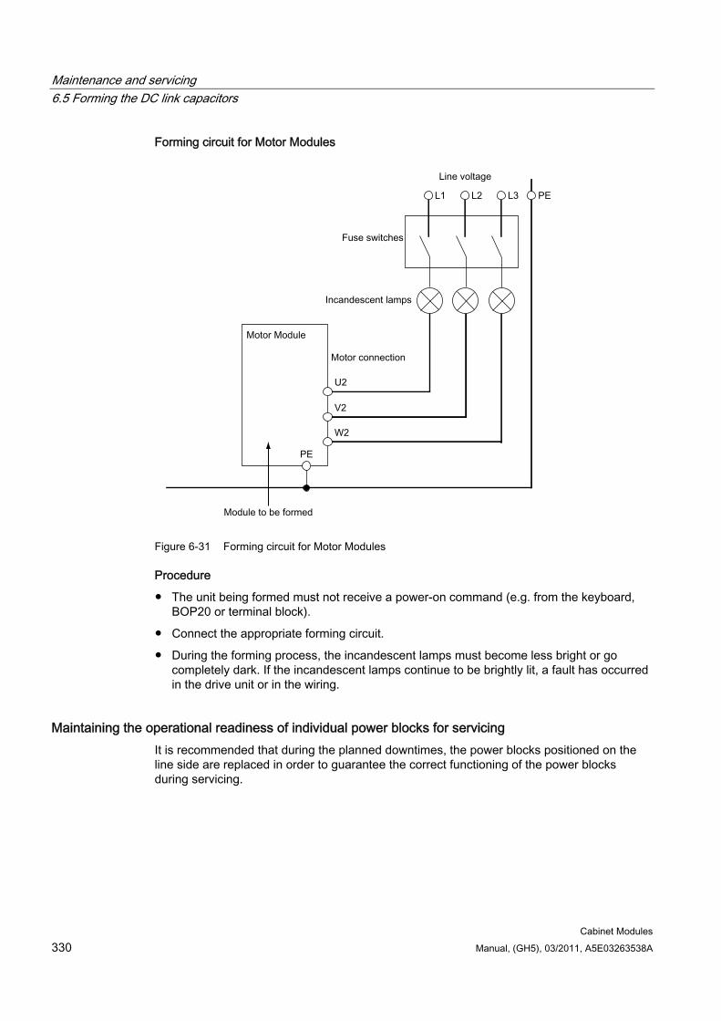
Maintenance and servicing 6.5 Forming the DC link capacitors
Cabinet Modules 330 Manual, (GH5), 03/2011, A5E03263538A
Forming circuit for Motor Modules
Figure 6-31 Forming circuit for Motor Modules
Procedure
The unit being formed must not receive a power-on command (e.g. from the keyboard, BOP20 or terminal block).
Connect the appropriate forming circuit.
During the forming process, the incandescent lamps must become less bright or go completely dark. If the incandescent lamps continue to be brightly lit, a fault has occurred in the drive unit or in the wiring.
Maintaining the operational readiness of individual power blocks for servicing It is recommended that during the planned downtimes, the power blocks positioned on the line side are replaced in order to guarantee the correct functioning of the power blocks during servicing.
Cabinet Modules Manual, (GH5), 03/2011, A5E03263538A 331
Diagnostics 77.1 Chapter content
This chapter provides an overview of the LEDs on the various cabinet unit components. Detailed descriptions of the components are provided either in this Manual or in the additional documentation on the customer DVD supplied with the device.
The overview of the LEDs provided here is intended for rapid diagnostic purposes.
7.2 LEDs on the CU320-2 DP Control Unit
Description of the LED states The different states while booting are indicated using LEDs on the Control Unit.
The duration of the individual states varies.
If an error occurs, the booting procedure is terminated and the cause is indicated on the LEDs.
Once the unit has successfully booted, all the LEDs are briefly switched off.
Once the unit has booted, the LEDs are controlled via the loaded software.
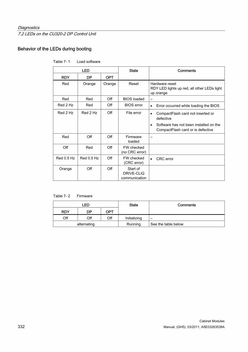
Diagnostics 7.2 LEDs on the CU320-2 DP Control Unit
Cabinet Modules 332 Manual, (GH5), 03/2011, A5E03263538A
Behavior of the LEDs during booting
Table 7- 1 Load software
LED
RDY DP OPT
State Comments
Red Orange Orange Reset Hardware reset RDY LED lights up red, all other LEDs light up orange
Red Red Off BIOS loaded – Red 2 Hz Red Off BIOS error Error occurred while loading the BIOS
Red 2 Hz Red 2 Hz Off File error CompactFlash card not inserted or defective
Software has not been installed on the CompactFlash card or is defective
Red Off Off Firmware loaded
–
Off Red Off FW checked (no CRC error)
Red 0.5 Hz Red 0.5 Hz Off FW checked (CRC error)
CRC error
Orange Off Off Start of DRIVE-CLiQ
communication
Table 7- 2 Firmware
LED
RDY DP OPT
State Comments
Off Off Off Initializing – alternating Running See the table below
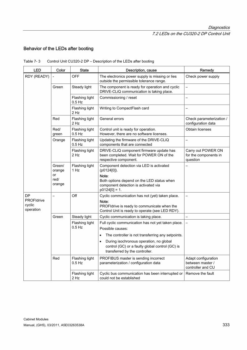
Diagnostics 7.2 LEDs on the CU320-2 DP Control Unit
Cabinet Modules Manual, (GH5), 03/2011, A5E03263538A 333
Behavior of the LEDs after booting
Table 7- 3 Control Unit CU320-2 DP – Description of the LEDs after booting
LED Color State Description, cause Remedy - OFF The electronics power supply is missing or lies
outside the permissible tolerance range. Check power supply
Steady light The component is ready for operation and cyclic DRIVE-CLiQ communication is taking place.
–
Flashing light 0.5 Hz
Commissioning / reset –
Green
Flashing light 2 Hz
Writing to CompactFlash card –
Red Flashing light 2 Hz
General errors Check parameterization / configuration data
Red/ green
Flashing light 0.5 Hz
Control unit is ready for operation. However, there are no software licenses.
Obtain licenses
Flashing light 0.5 Hz
Updating the firmware of the DRIVE-CLiQ components that are connected
– Orange
Flashing light 2 Hz
DRIVE-CLiQ component firmware update has been completed. Wait for POWER ON of the respective component.
Carry out POWER ON for the components in question
RDY (READY)
Green/ orange or red/ orange
Flashing light 1 Hz
Component detection via LED is activated (p0124[0]). Note: Both options depend on the LED status when component detection is activated via p0124[0] = 1.
–
– Off Cyclic communication has not (yet) taken place. Note: PROFIdrive is ready to communicate when the Control Unit is ready to operate (see LED RDY).
–
Steady light Cyclic communication is taking place. – Green Flashing light 0.5 Hz
Full cyclic communication has not yet taken place. Possible causes: The controller is not transferring any setpoints. During isochronous operation, no global
control (GC) or a faulty global control (GC) is transferred by the controller.
–
Flashing light 0.5 Hz
PROFIBUS master is sending incorrect parameterization / configuration data
Adapt configuration between master / controller and CU
DP PROFIdrive cyclic operation
Red
Flashing light 2 Hz
Cyclic bus communication has been interrupted or could not be established
Remove the fault
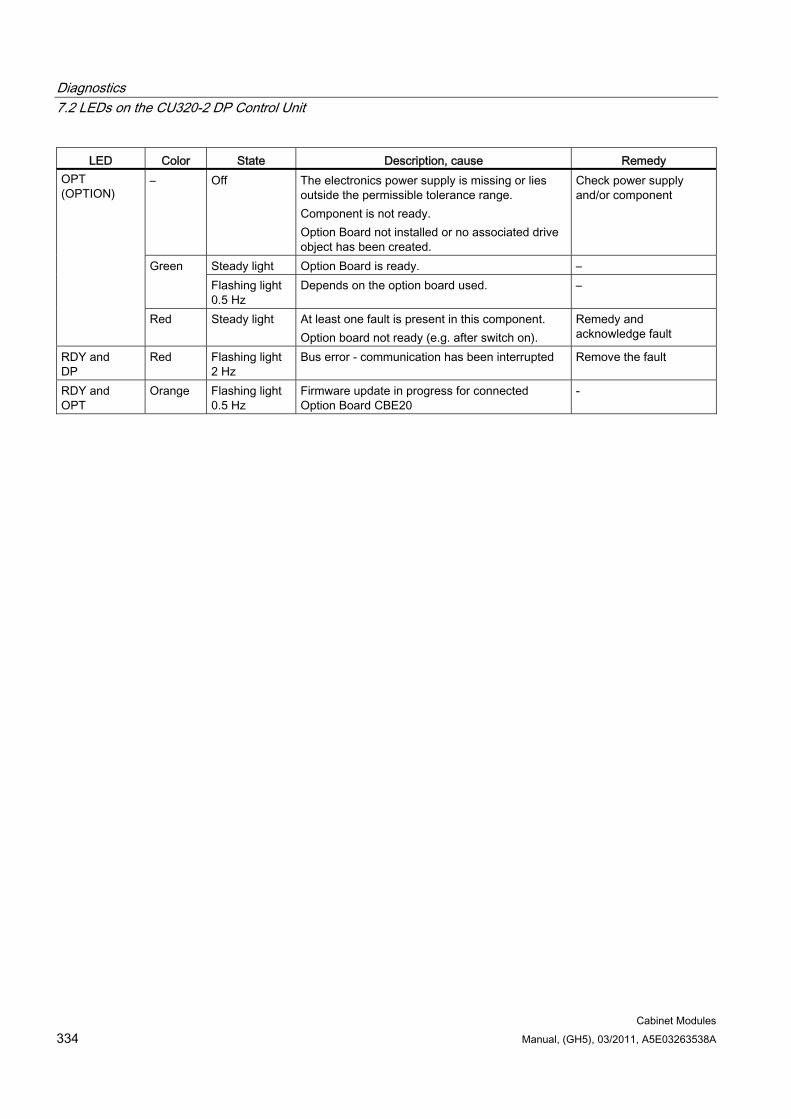
Diagnostics 7.2 LEDs on the CU320-2 DP Control Unit
Cabinet Modules 334 Manual, (GH5), 03/2011, A5E03263538A
LED Color State Description, cause Remedy – Off The electronics power supply is missing or lies
outside the permissible tolerance range. Component is not ready. Option Board not installed or no associated drive object has been created.
Check power supply and/or component
Steady light Option Board is ready. – Green Flashing light 0.5 Hz
Depends on the option board used. –
OPT (OPTION)
Red Steady light At least one fault is present in this component. Option board not ready (e.g. after switch on).
Remedy and acknowledge fault
RDY and DP
Red Flashing light 2 Hz
Bus error - communication has been interrupted Remove the fault
RDY and OPT
Orange Flashing light 0.5 Hz
Firmware update in progress for connected Option Board CBE20
-
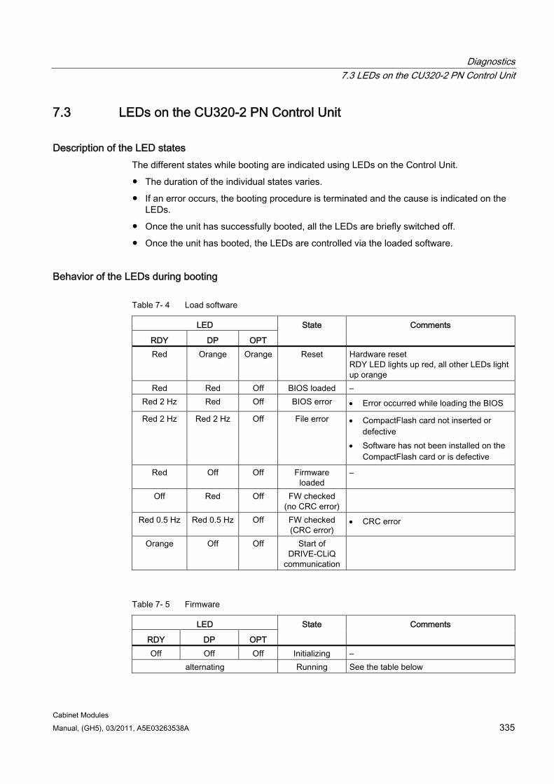
Diagnostics 7.3 LEDs on the CU320-2 PN Control Unit
Cabinet Modules Manual, (GH5), 03/2011, A5E03263538A 335
7.3 LEDs on the CU320-2 PN Control Unit
Description of the LED states The different states while booting are indicated using LEDs on the Control Unit.
The duration of the individual states varies.
If an error occurs, the booting procedure is terminated and the cause is indicated on the LEDs.
Once the unit has successfully booted, all the LEDs are briefly switched off.
Once the unit has booted, the LEDs are controlled via the loaded software.
Behavior of the LEDs during booting
Table 7- 4 Load software
LED
RDY DP OPT
State Comments
Red Orange Orange Reset Hardware reset RDY LED lights up red, all other LEDs light up orange
Red Red Off BIOS loaded – Red 2 Hz Red Off BIOS error Error occurred while loading the BIOS
Red 2 Hz Red 2 Hz Off File error CompactFlash card not inserted or defective
Software has not been installed on the CompactFlash card or is defective
Red Off Off Firmware loaded
–
Off Red Off FW checked (no CRC error)
Red 0.5 Hz Red 0.5 Hz Off FW checked (CRC error)
CRC error
Orange Off Off Start of DRIVE-CLiQ
communication
Table 7- 5 Firmware
LED
RDY DP OPT
State Comments
Off Off Off Initializing – alternating Running See the table below
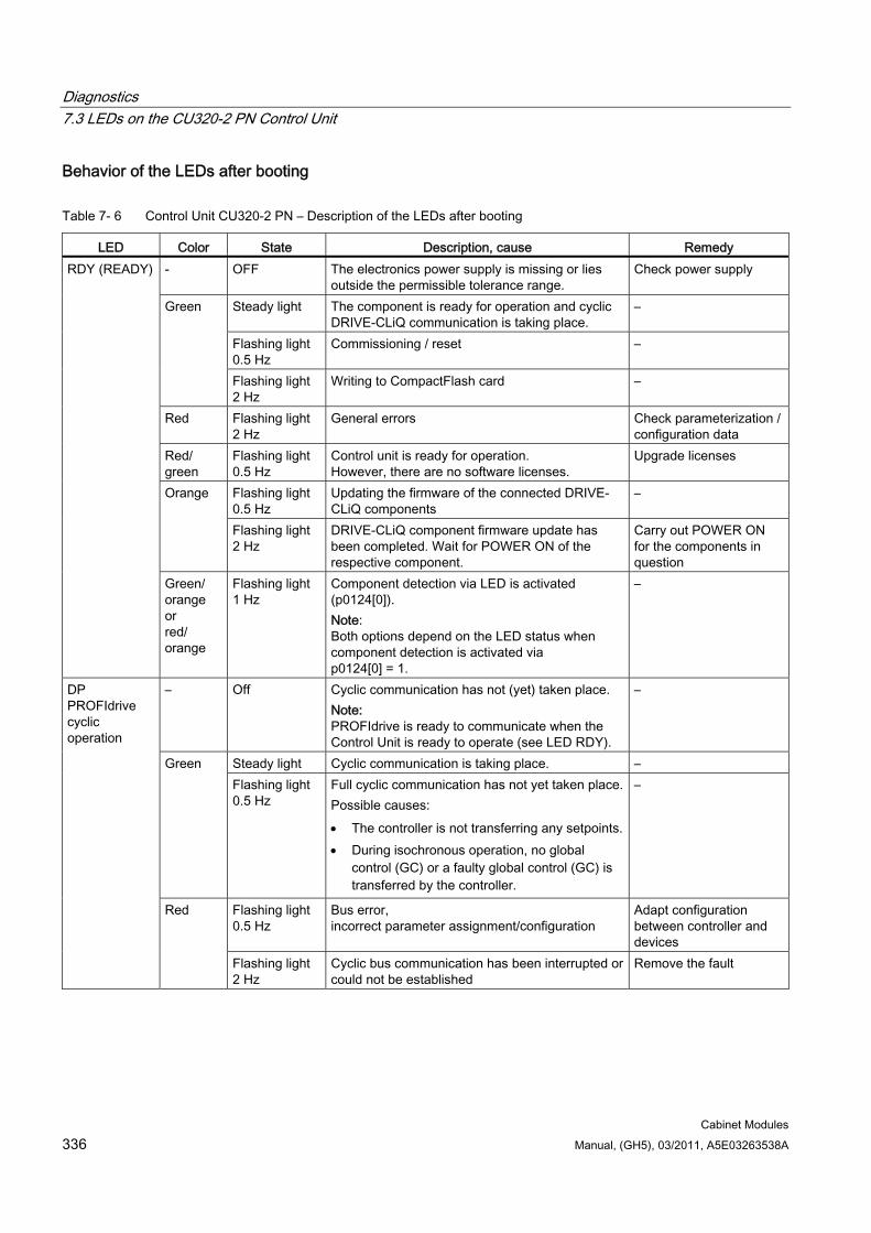
Diagnostics 7.3 LEDs on the CU320-2 PN Control Unit
Cabinet Modules 336 Manual, (GH5), 03/2011, A5E03263538A
Behavior of the LEDs after booting
Table 7- 6 Control Unit CU320-2 PN – Description of the LEDs after booting
LED Color State Description, cause Remedy - OFF The electronics power supply is missing or lies
outside the permissible tolerance range. Check power supply
Steady light The component is ready for operation and cyclic DRIVE-CLiQ communication is taking place.
–
Flashing light 0.5 Hz
Commissioning / reset –
Green
Flashing light 2 Hz
Writing to CompactFlash card –
Red Flashing light 2 Hz
General errors Check parameterization / configuration data
Red/ green
Flashing light 0.5 Hz
Control unit is ready for operation. However, there are no software licenses.
Upgrade licenses
Flashing light 0.5 Hz
Updating the firmware of the connected DRIVE-CLiQ components
– Orange
Flashing light 2 Hz
DRIVE-CLiQ component firmware update has been completed. Wait for POWER ON of the respective component.
Carry out POWER ON for the components in question
RDY (READY)
Green/ orange or red/ orange
Flashing light 1 Hz
Component detection via LED is activated (p0124[0]). Note: Both options depend on the LED status when component detection is activated via p0124[0] = 1.
–
– Off Cyclic communication has not (yet) taken place. Note: PROFIdrive is ready to communicate when the Control Unit is ready to operate (see LED RDY).
–
Steady light Cyclic communication is taking place. – Green Flashing light 0.5 Hz
Full cyclic communication has not yet taken place. Possible causes: The controller is not transferring any setpoints. During isochronous operation, no global
control (GC) or a faulty global control (GC) is transferred by the controller.
–
Flashing light 0.5 Hz
Bus error, incorrect parameter assignment/configuration
Adapt configuration between controller and devices
DP PROFIdrive cyclic operation
Red
Flashing light 2 Hz
Cyclic bus communication has been interrupted or could not be established
Remove the fault
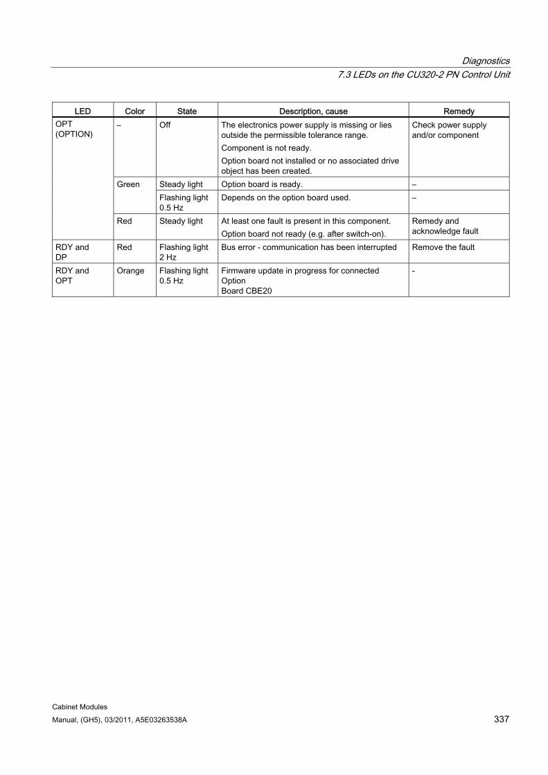
Diagnostics 7.3 LEDs on the CU320-2 PN Control Unit
Cabinet Modules Manual, (GH5), 03/2011, A5E03263538A 337
LED Color State Description, cause Remedy – Off The electronics power supply is missing or lies
outside the permissible tolerance range. Component is not ready. Option board not installed or no associated drive object has been created.
Check power supply and/or component
Steady light Option board is ready. – Green Flashing light 0.5 Hz
Depends on the option board used. –
OPT (OPTION)
Red Steady light At least one fault is present in this component. Option board not ready (e.g. after switch-on).
Remedy and acknowledge fault
RDY and DP
Red Flashing light 2 Hz
Bus error - communication has been interrupted Remove the fault
RDY and OPT
Orange Flashing light 0.5 Hz
Firmware update in progress for connected Option Board CBE20
-
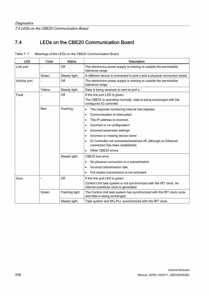
Diagnostics 7.4 LEDs on the CBE20 Communication Board
Cabinet Modules 338 Manual, (GH5), 03/2011, A5E03263538A
7.4 LEDs on the CBE20 Communication Board
Table 7- 7 Meanings of the LEDs on the CBE20 Communication Board
LED Color Status Description - Off The electronics power supply is missing or outside the permissible
tolerance range. Link port
Green Steady light A different device is connected to port x and a physical connection exists.- Off The electronics power supply is missing or outside the permissible
tolerance range. Activity port
Yellow Steady light Data is being received or sent at port x. – Off If the link port LED is green:
The CBE20 is operating normally, data is being exchanged with the configured IO controller.
Flashing The response monitoring interval has elapsed. Communication is interrupted. The IP address is incorrect. Incorrect or no configuration Incorrect parameter settings Incorrect or missing device name IO Controller not connected/switched off, although an Ethernet
connection has been established. Other CBE20 errors
Fault
Red
Steady light CBE20 bus error No physical connection to a subnet/switch. Incorrect transmission rate Full duplex transmission is not activated.
– Off If the link port LED is green: Control Unit task system is not synchronized with the IRT clock. An internal substitute clock is generated.
Flashing light The Control Unit task system has synchronized with the IRT clock cycle and data is being exchanged.
Sync
Green
Steady light Task system and MC-PLL synchronized with the IRT clock.
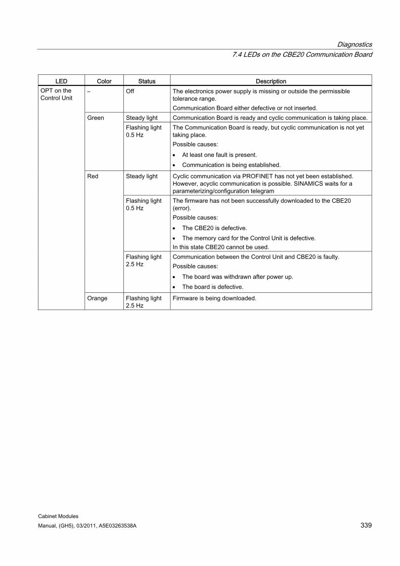
Diagnostics 7.4 LEDs on the CBE20 Communication Board
Cabinet Modules Manual, (GH5), 03/2011, A5E03263538A 339
LED Color Status Description – Off The electronics power supply is missing or outside the permissible
tolerance range. Communication Board either defective or not inserted.
Steady light Communication Board is ready and cyclic communication is taking place. Green Flashing light 0.5 Hz
The Communication Board is ready, but cyclic communication is not yet taking place. Possible causes: At least one fault is present. Communication is being established.
Steady light Cyclic communication via PROFINET has not yet been established. However, acyclic communication is possible. SINAMICS waits for a parameterizing/configuration telegram
Flashing light 0.5 Hz
The firmware has not been successfully downloaded to the CBE20 (error). Possible causes: The CBE20 is defective. The memory card for the Control Unit is defective. In this state CBE20 cannot be used.
Red
Flashing light 2.5 Hz
Communication between the Control Unit and CBE20 is faulty. Possible causes: The board was withdrawn after power up. The board is defective.
OPT on the Control Unit
Orange Flashing light 2.5 Hz
Firmware is being downloaded.
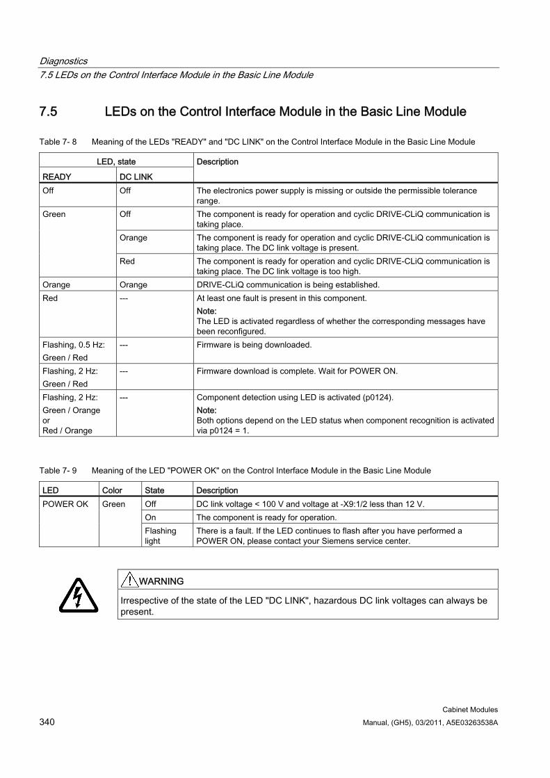
Diagnostics 7.5 LEDs on the Control Interface Module in the Basic Line Module
Cabinet Modules 340 Manual, (GH5), 03/2011, A5E03263538A
7.5 LEDs on the Control Interface Module in the Basic Line Module
Table 7- 8 Meaning of the LEDs "READY" and "DC LINK" on the Control Interface Module in the Basic Line Module
LED, state
READY DC LINK
Description
Off Off The electronics power supply is missing or outside the permissible tolerance range.
Off The component is ready for operation and cyclic DRIVE-CLiQ communication is taking place.
Orange The component is ready for operation and cyclic DRIVE-CLiQ communication is taking place. The DC link voltage is present.
Green
Red The component is ready for operation and cyclic DRIVE-CLiQ communication is taking place. The DC link voltage is too high.
Orange Orange DRIVE-CLiQ communication is being established. Red --- At least one fault is present in this component.
Note: The LED is activated regardless of whether the corresponding messages have been reconfigured.
Flashing, 0.5 Hz: Green / Red
--- Firmware is being downloaded.
Flashing, 2 Hz: Green / Red
--- Firmware download is complete. Wait for POWER ON.
Flashing, 2 Hz: Green / Orange or Red / Orange
--- Component detection using LED is activated (p0124). Note: Both options depend on the LED status when component recognition is activated via p0124 = 1.
Table 7- 9 Meaning of the LED "POWER OK" on the Control Interface Module in the Basic Line Module
LED Color State Description Off DC link voltage < 100 V and voltage at -X9:1/2 less than 12 V. On The component is ready for operation.
POWER OK Green
Flashing light
There is a fault. If the LED continues to flash after you have performed a POWER ON, please contact your Siemens service center.
WARNING
Irrespective of the state of the LED "DC LINK", hazardous DC link voltages can always be present.
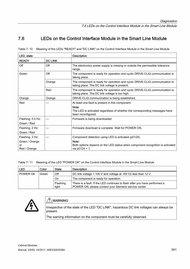
Diagnostics 7.6 LEDs on the Control Interface Module in the Smart Line Module
Cabinet Modules Manual, (GH5), 03/2011, A5E03263538A 341
7.6 LEDs on the Control Interface Module in the Smart Line Module
Table 7- 10 Meaning of the LEDs "READY" and "DC LINK" on the Control Interface Module in the Smart Line Module
LED, state Description READY DC LINK Off Off The electronics power supply is missing or outside the permissible tolerance
range. Off The component is ready for operation and cyclic DRIVE-CLiQ communication is
taking place. Orange The component is ready for operation and cyclic DRIVE-CLiQ communication is
taking place. The DC link voltage is present.
Green
Red The component is ready for operation and cyclic DRIVE-CLiQ communication is taking place. The DC link voltage is too high.
Orange Orange DRIVE-CLiQ communication is being established. Red --- At least one fault is present in this component.
Note: The LED is activated regardless of whether the corresponding messages have been reconfigured.
Flashing, 0.5 Hz: Green / Red
--- Firmware is being downloaded.
Flashing, 2 Hz: Green / Red
--- Firmware download is complete. Wait for POWER ON.
Flashing, 2 Hz: Green / Orange or Red / Orange
--- Component detection using LED is activated (p0124). Note: Both options depend on the LED status when component recognition is activated via p0124 = 1.
Table 7- 11 Meaning of the LED "POWER OK" on the Control Interface Module in the Smart Line Module
LED Color State Description Off DC link voltage < 100 V and voltage at -X9:1/2 less than 12 V. On The component is ready for operation.
POWER OK Green
Flashing light
There is a fault. If the LED continues to flash after you have performed a POWER ON, please contact your Siemens service center.
WARNING
Irrespective of the state of the LED "DC LINK", hazardous DC link voltages can always be present.
The warning information on the component must be carefully observed.
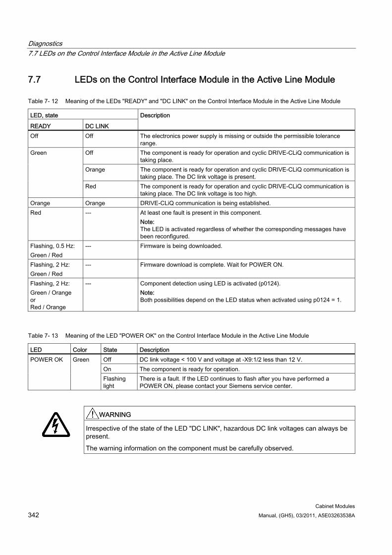
Diagnostics 7.7 LEDs on the Control Interface Module in the Active Line Module
Cabinet Modules 342 Manual, (GH5), 03/2011, A5E03263538A
7.7 LEDs on the Control Interface Module in the Active Line Module
Table 7- 12 Meaning of the LEDs "READY" and "DC LINK" on the Control Interface Module in the Active Line Module
LED, state
READY DC LINK
Description
Off Off The electronics power supply is missing or outside the permissible tolerance range.
Off The component is ready for operation and cyclic DRIVE-CLiQ communication is taking place.
Orange The component is ready for operation and cyclic DRIVE-CLiQ communication is taking place. The DC link voltage is present.
Green
Red The component is ready for operation and cyclic DRIVE-CLiQ communication is taking place. The DC link voltage is too high.
Orange Orange DRIVE-CLiQ communication is being established. Red --- At least one fault is present in this component.
Note: The LED is activated regardless of whether the corresponding messages have been reconfigured.
Flashing, 0.5 Hz: Green / Red
--- Firmware is being downloaded.
Flashing, 2 Hz: Green / Red
--- Firmware download is complete. Wait for POWER ON.
Flashing, 2 Hz: Green / Orange or Red / Orange
--- Component detection using LED is activated (p0124). Note: Both possibilities depend on the LED status when activated using p0124 = 1.
Table 7- 13 Meaning of the LED "POWER OK" on the Control Interface Module in the Active Line Module
LED Color State Description Off DC link voltage < 100 V and voltage at -X9:1/2 less than 12 V. On The component is ready for operation.
POWER OK Green
Flashing light
There is a fault. If the LED continues to flash after you have performed a POWER ON, please contact your Siemens service center.
WARNING
Irrespective of the state of the LED "DC LINK", hazardous DC link voltages can always be present.
The warning information on the component must be carefully observed.
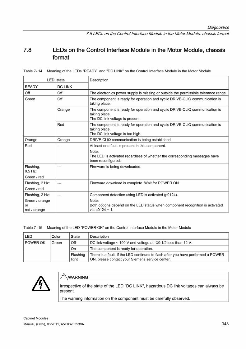
Diagnostics 7.8 LEDs on the Control Interface Module in the Motor Module, chassis format
Cabinet Modules Manual, (GH5), 03/2011, A5E03263538A 343
7.8 LEDs on the Control Interface Module in the Motor Module, chassis format
Table 7- 14 Meaning of the LEDs "READY" and "DC LINK" on the Control Interface Module in the Motor Module
LED, state
READY DC LINK
Description
Off Off The electronics power supply is missing or outside the permissible tolerance range.Off The component is ready for operation and cyclic DRIVE-CLiQ communication is
taking place. Orange The component is ready for operation and cyclic DRIVE-CLiQ communication is
taking place. The DC link voltage is present.
Green
Red The component is ready for operation and cyclic DRIVE-CLiQ communication is taking place. The DC link voltage is too high.
Orange Orange DRIVE-CLiQ communication is being established. Red --- At least one fault is present in this component.
Note: The LED is activated regardless of whether the corresponding messages have been reconfigured.
Flashing, 0.5 Hz: Green / red
--- Firmware is being downloaded.
Flashing, 2 Hz: Green / red
--- Firmware download is complete. Wait for POWER ON.
Flashing, 2 Hz: Green / orange or red / orange
--- Component detection using LED is activated (p0124). Note: Both options depend on the LED status when component recognition is activated via p0124 = 1.
Table 7- 15 Meaning of the LED "POWER OK" on the Control Interface Module in the Motor Module
LED Color State Description Off DC link voltage < 100 V and voltage at -X9:1/2 less than 12 V. On The component is ready for operation.
POWER OK Green
Flashing light
There is a fault. If the LED continues to flash after you have performed a POWER ON, please contact your Siemens service center.
WARNING
Irrespective of the state of the LED "DC LINK", hazardous DC link voltages can always be present.
The warning information on the component must be carefully observed.
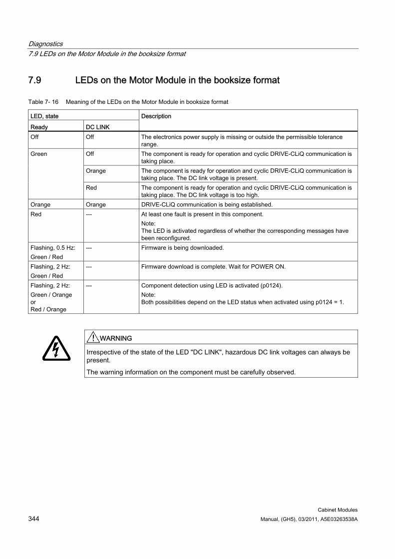
Diagnostics 7.9 LEDs on the Motor Module in the booksize format
Cabinet Modules 344 Manual, (GH5), 03/2011, A5E03263538A
7.9 LEDs on the Motor Module in the booksize format
Table 7- 16 Meaning of the LEDs on the Motor Module in booksize format
LED, state
Ready DC LINK
Description
Off Off The electronics power supply is missing or outside the permissible tolerance range.
Off The component is ready for operation and cyclic DRIVE-CLiQ communication is taking place.
Orange The component is ready for operation and cyclic DRIVE-CLiQ communication is taking place. The DC link voltage is present.
Green
Red The component is ready for operation and cyclic DRIVE-CLiQ communication is taking place. The DC link voltage is too high.
Orange Orange DRIVE-CLiQ communication is being established. Red --- At least one fault is present in this component.
Note: The LED is activated regardless of whether the corresponding messages have been reconfigured.
Flashing, 0.5 Hz: Green / Red
--- Firmware is being downloaded.
Flashing, 2 Hz: Green / Red
--- Firmware download is complete. Wait for POWER ON.
Flashing, 2 Hz: Green / Orange or Red / Orange
--- Component detection using LED is activated (p0124). Note: Both possibilities depend on the LED status when activated using p0124 = 1.
WARNING
Irrespective of the state of the LED "DC LINK", hazardous DC link voltages can always be present.
The warning information on the component must be carefully observed.
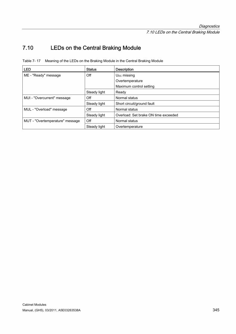
Diagnostics 7.10 LEDs on the Central Braking Module
Cabinet Modules Manual, (GH5), 03/2011, A5E03263538A 345
7.10 LEDs on the Central Braking Module
Table 7- 17 Meaning of the LEDs on the Braking Module in the Central Braking Module
LED Status Description Off UDC missing
Overtemperature Maximum control setting
ME - "Ready" message
Steady light Ready Off Normal status MUI - "Overcurrent" message Steady light Short circuit/ground fault Off Normal status MUL - "Overload" message Steady light Overload: Set brake ON time exceeded Off Normal status MUT - "Overtemperature" message Steady light Overtemperature
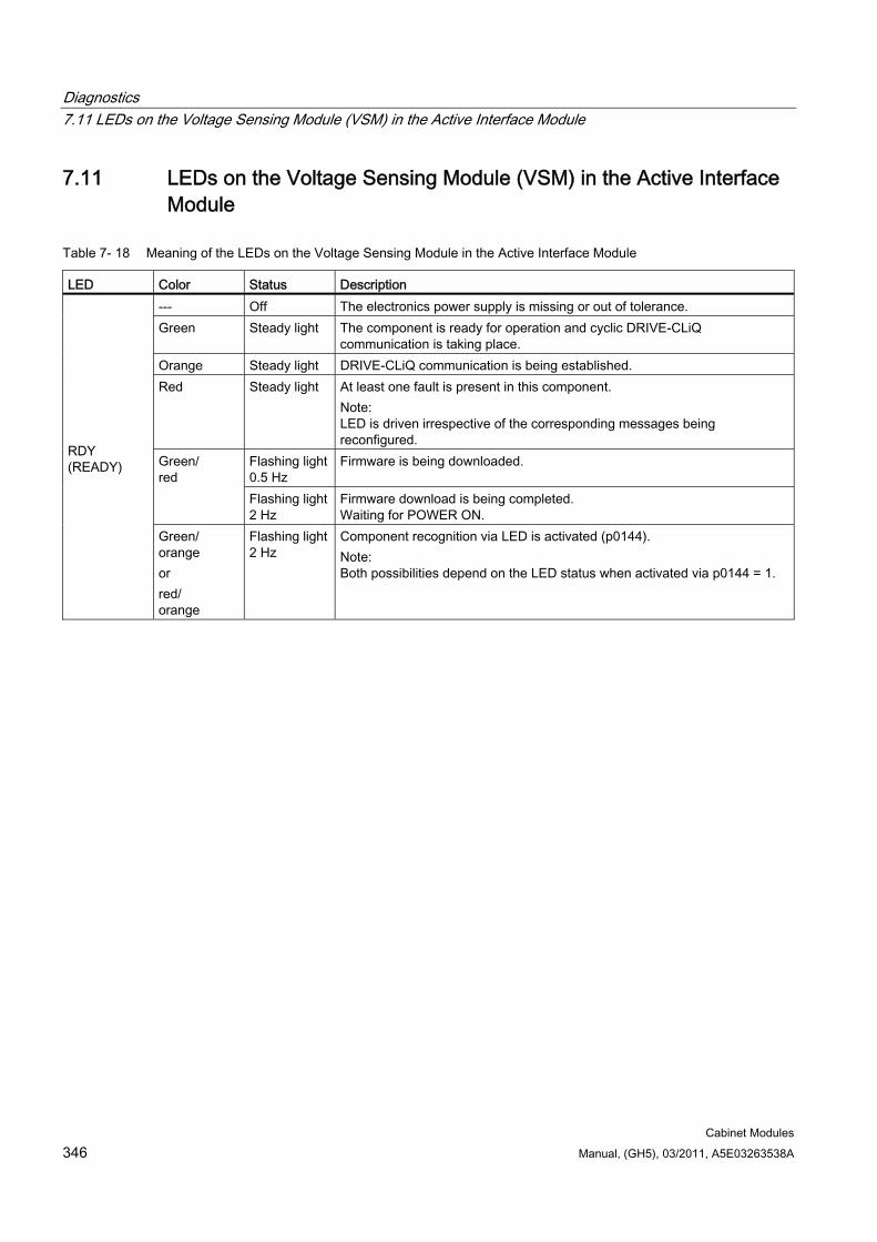
Diagnostics 7.11 LEDs on the Voltage Sensing Module (VSM) in the Active Interface Module
Cabinet Modules 346 Manual, (GH5), 03/2011, A5E03263538A
7.11 LEDs on the Voltage Sensing Module (VSM) in the Active Interface Module
Table 7- 18 Meaning of the LEDs on the Voltage Sensing Module in the Active Interface Module
LED Color Status Description --- Off The electronics power supply is missing or out of tolerance. Green Steady light The component is ready for operation and cyclic DRIVE-CLiQ
communication is taking place. Orange Steady light DRIVE-CLiQ communication is being established. Red Steady light At least one fault is present in this component.
Note: LED is driven irrespective of the corresponding messages being reconfigured.
Flashing light 0.5 Hz
Firmware is being downloaded. Green/ red
Flashing light 2 Hz
Firmware download is being completed. Waiting for POWER ON.
RDY (READY)
Green/ orange or red/ orange
Flashing light 2 Hz
Component recognition via LED is activated (p0144). Note: Both possibilities depend on the LED status when activated via p0144 = 1.
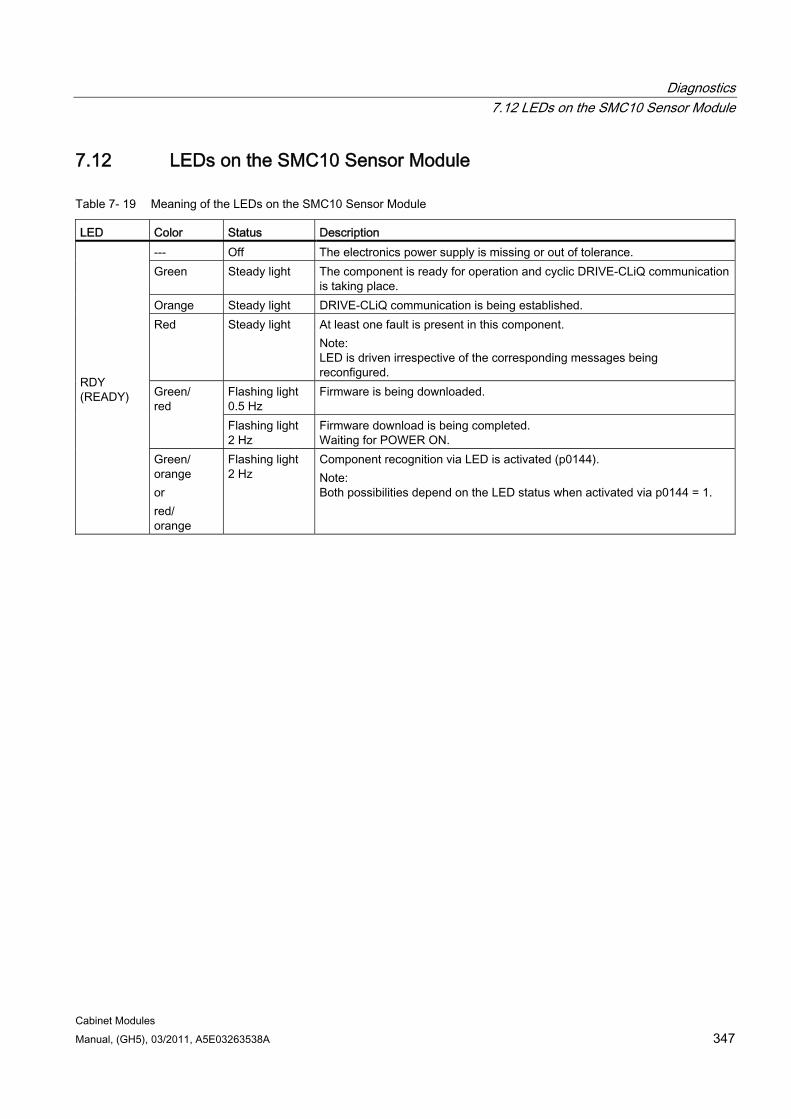
Diagnostics 7.12 LEDs on the SMC10 Sensor Module
Cabinet Modules Manual, (GH5), 03/2011, A5E03263538A 347
7.12 LEDs on the SMC10 Sensor Module
Table 7- 19 Meaning of the LEDs on the SMC10 Sensor Module
LED Color Status Description --- Off The electronics power supply is missing or out of tolerance. Green Steady light The component is ready for operation and cyclic DRIVE-CLiQ communication
is taking place. Orange Steady light DRIVE-CLiQ communication is being established. Red Steady light At least one fault is present in this component.
Note: LED is driven irrespective of the corresponding messages being reconfigured.
Flashing light 0.5 Hz
Firmware is being downloaded. Green/ red
Flashing light 2 Hz
Firmware download is being completed. Waiting for POWER ON.
RDY (READY)
Green/ orange or red/ orange
Flashing light 2 Hz
Component recognition via LED is activated (p0144). Note: Both possibilities depend on the LED status when activated via p0144 = 1.
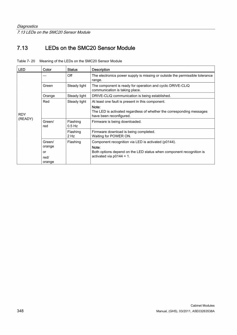
Diagnostics 7.13 LEDs on the SMC20 Sensor Module
Cabinet Modules 348 Manual, (GH5), 03/2011, A5E03263538A
7.13 LEDs on the SMC20 Sensor Module
Table 7- 20 Meaning of the LEDs on the SMC20 Sensor Module
LED Color Status Description --- Off The electronics power supply is missing or outside the permissible tolerance
range. Green Steady light The component is ready for operation and cyclic DRIVE-CLiQ
communication is taking place. Orange Steady light DRIVE-CLiQ communication is being established. Red Steady light At least one fault is present in this component.
Note: The LED is activated regardless of whether the corresponding messages have been reconfigured.
Flashing 0.5 Hz
Firmware is being downloaded. Green/ red
Flashing 2 Hz
Firmware download is being completed. Waiting for POWER ON.
RDY (READY)
Green/ orange or red/ orange
Flashing Component recognition via LED is activated (p0144). Note: Both options depend on the LED status when component recognition is activated via p0144 = 1.
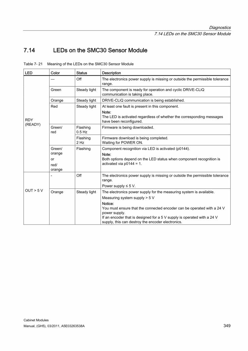
Diagnostics 7.14 LEDs on the SMC30 Sensor Module
Cabinet Modules Manual, (GH5), 03/2011, A5E03263538A 349
7.14 LEDs on the SMC30 Sensor Module
Table 7- 21 Meaning of the LEDs on the SMC30 Sensor Module
LED Color Status Description --- Off The electronics power supply is missing or outside the permissible tolerance
range. Green Steady light The component is ready for operation and cyclic DRIVE-CLiQ
communication is taking place. Orange Steady light DRIVE-CLiQ communication is being established. Red Steady light At least one fault is present in this component.
Note: The LED is activated regardless of whether the corresponding messages have been reconfigured.
Flashing 0.5 Hz
Firmware is being downloaded. Green/ red
Flashing 2 Hz
Firmware download is being completed. Waiting for POWER ON.
RDY (READY)
Green/ orange or red/ orange
Flashing
Component recognition via LED is activated (p0144). Note: Both options depend on the LED status when component recognition is activated via p0144 = 1.
- Off The electronics power supply is missing or outside the permissible tolerance range. Power supply ≤ 5 V.
OUT > 5 V Orange Steady light The electronics power supply for the measuring system is available.
Measuring system supply > 5 V Notice: You must ensure that the connected encoder can be operated with a 24 V power supply. If an encoder that is designed for a 5 V supply is operated with a 24 V supply, this can destroy the encoder electronics.
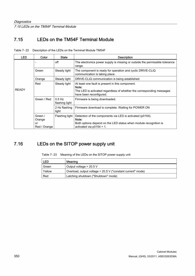
Diagnostics 7.15 LEDs on the TM54F Terminal Module
Cabinet Modules 350 Manual, (GH5), 03/2011, A5E03263538A
7.15 LEDs on the TM54F Terminal Module
Table 7- 22 Description of the LEDs on the Terminal Module TM54F
LED Color State Description - off The electronics power supply is missing or outside the permissible tolerance
range. Green Steady light The component is ready for operation and cyclic DRIVE-CLiQ
communication is taking place. Orange Steady light DRIVE-CLiQ communication is being established. Red Steady light At least one fault is present in this component.
Note: The LED is activated regardless of whether the corresponding messages have been reconfigured.
0.5 Hz flashing light
Firmware is being downloaded. Green / Red
2 Hz flashing light
Firmware download is complete. Waiting for POWER ON
READY
Green / Orange or Red / Orange
Flashing light Detection of the components via LED is activated (p0154). Note: Both options depend on the LED status when module recognition is activated via p0154 = 1.
7.16 LEDs on the SITOP power supply unit
Table 7- 23 Meaning of the LEDs on the SITOP power supply unit
LED Meaning Green Output voltage > 20.5 V Yellow Overload, output voltage < 20.5 V ("constant current" mode) Red Latching shutdown ("Shutdown" mode)
Cabinet Modules Manual, (GH5), 03/2011, A5E03263538A 351
Options 88.1 Safety information
DANGER
You must read and observe the "Safety information" chapter in this Manual.
When carrying out any kind of work on electrical devices, the following "five safety rules" must always be observed in accordance with EN 50110-1 and EN 50110-2: 1. Disconnect from power supply. 2. Protect against reconnection. 3. Make sure that the equipment is de-energized. 4. Ground and short-circuit. 5. Cover or enclose adjacent components that are still live.
DANGER
The cabinet units are operated with high voltages. All connection work must be carried out when the cabinet is de-energized. All work on the unit must be carried out by trained personnel only.
Work on an open cabinet must be carried out with extreme caution because external supply voltages may be present. The power and control terminals may be live even when the motor is not running. Dangerously high voltage levels are still present in the unit up to 5 minutes after it has been disconnected due to the DC link capacitors. For this reason, the cabinet should not be opened until a reasonable period of time has elapsed.
The user is responsible for ensuring that the motor, inverter, and other devices are installed and connected in accordance with the recognized technical rules in the country of installation and with other applicable regional regulations. Special attention should be paid to cable dimensioning, fuses, grounding, shutdown, disconnection, and overcurrent protection.
If an item of protective gear trips in a branch circuit, a leakage current may have been disconnected. To reduce the risk of fire or an electric shock, the current-conducting parts and other components in the cabinet should be inspected and damaged parts replaced. When an item of protective gear trips, the cause of the trip must be identified and rectified.
Options 8.2 D14, Preliminary copy of customer documentation
Cabinet Modules 352 Manual, (GH5), 03/2011, A5E03263538A
Note
The Cabinet Modules come in a range of different frame sizes, with each size differing from the others in several ways. The main differences are: The covers used can have different dimensions, and they can be arranged and secured
in different ways. The components can be arranged differently within the cabinet units. The components can be mounted within the cabinet units using different methods.
These variations result from the different requirements made of the components/equipment installed in the cabinet units. These differences are intentional and exist for "EMC optimization" reasons.
8.2 D14, Preliminary copy of customer documentation If documents such as circuit diagrams, terminal diagrams, arrangement diagrams and dimension drawings are required for the system engineering (integration of the plant in higher-level systems, interface clarification, installation, building planning, etc.), advance documentation can also be ordered when ordering the cabinet modules. These documents are then supplied electronically a few working days after the order has been entered. If the order includes options that fall outside the scope of standard delivery, these will not be covered by the documentation due to the obvious time constraints.
Documentation relating to the order is sent to the buyer by e-mail. The recipient's e-mail address must be specified with the order for this purpose. In the e-mail, the recipient is also provided with a link for downloading general advance documentation such as operating instructions, Manual and commissioning instructions.
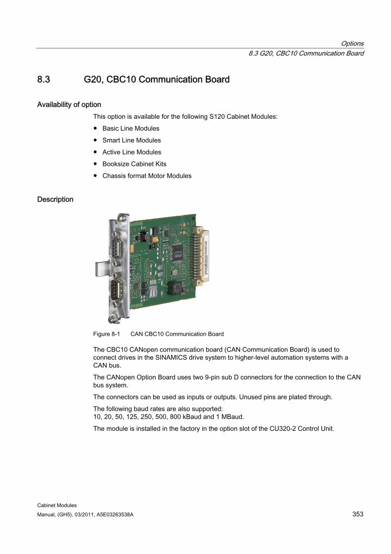
Options 8.3 G20, CBC10 Communication Board
Cabinet Modules Manual, (GH5), 03/2011, A5E03263538A 353
8.3 G20, CBC10 Communication Board
Availability of option This option is available for the following S120 Cabinet Modules:
Basic Line Modules
Smart Line Modules
Active Line Modules
Booksize Cabinet Kits
Chassis format Motor Modules
Description
Figure 8-1 CAN CBC10 Communication Board
The CBC10 CANopen communication board (CAN Communication Board) is used to connect drives in the SINAMICS drive system to higher-level automation systems with a CAN bus.
The CANopen Option Board uses two 9-pin sub D connectors for the connection to the CAN bus system.
The connectors can be used as inputs or outputs. Unused pins are plated through.
The following baud rates are also supported: 10, 20, 50, 125, 250, 500, 800 kBaud and 1 MBaud.
The module is installed in the factory in the option slot of the CU320-2 Control Unit.
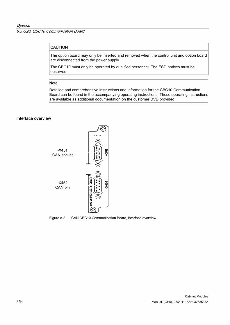
Options 8.3 G20, CBC10 Communication Board
Cabinet Modules 354 Manual, (GH5), 03/2011, A5E03263538A
CAUTION The option board may only be inserted and removed when the control unit and option board are disconnected from the power supply.
The CBC10 must only be operated by qualified personnel. The ESD notices must be observed.
Note
Detailed and comprehensive instructions and information for the CBC10 Communication Board can be found in the accompanying operating instructions, These operating instructions are available as additional documentation on the customer DVD provided.
Interface overview
Figure 8-2 CAN CBC10 Communication Board, interface overview
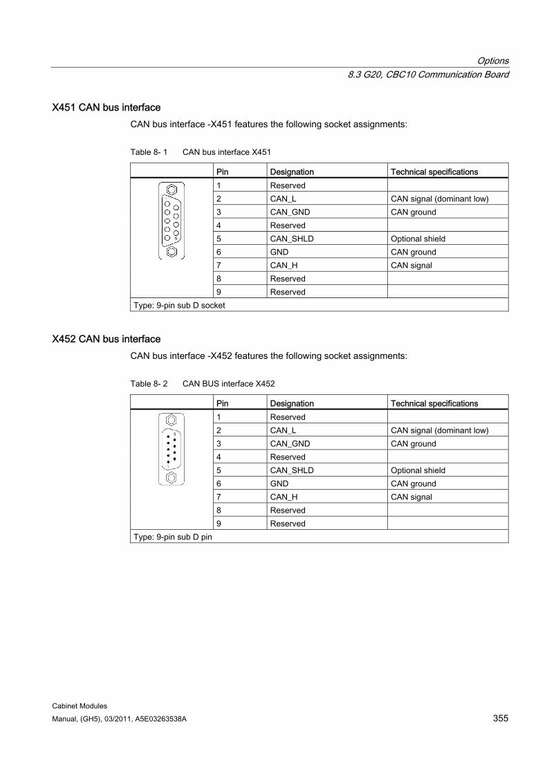
Options 8.3 G20, CBC10 Communication Board
Cabinet Modules Manual, (GH5), 03/2011, A5E03263538A 355
X451 CAN bus interface CAN bus interface -X451 features the following socket assignments:
Table 8- 1 CAN bus interface X451
Pin Designation Technical specifications 1 Reserved 2 CAN_L CAN signal (dominant low) 3 CAN_GND CAN ground 4 Reserved 5 CAN_SHLD Optional shield 6 GND CAN ground 7 CAN_H CAN signal 8 Reserved
9 Reserved Type: 9-pin sub D socket
X452 CAN bus interface CAN bus interface -X452 features the following socket assignments:
Table 8- 2 CAN BUS interface X452
Pin Designation Technical specifications 1 Reserved 2 CAN_L CAN signal (dominant low) 3 CAN_GND CAN ground 4 Reserved 5 CAN_SHLD Optional shield 6 GND CAN ground 7 CAN_H CAN signal 8 Reserved
9 Reserved Type: 9-pin sub D pin
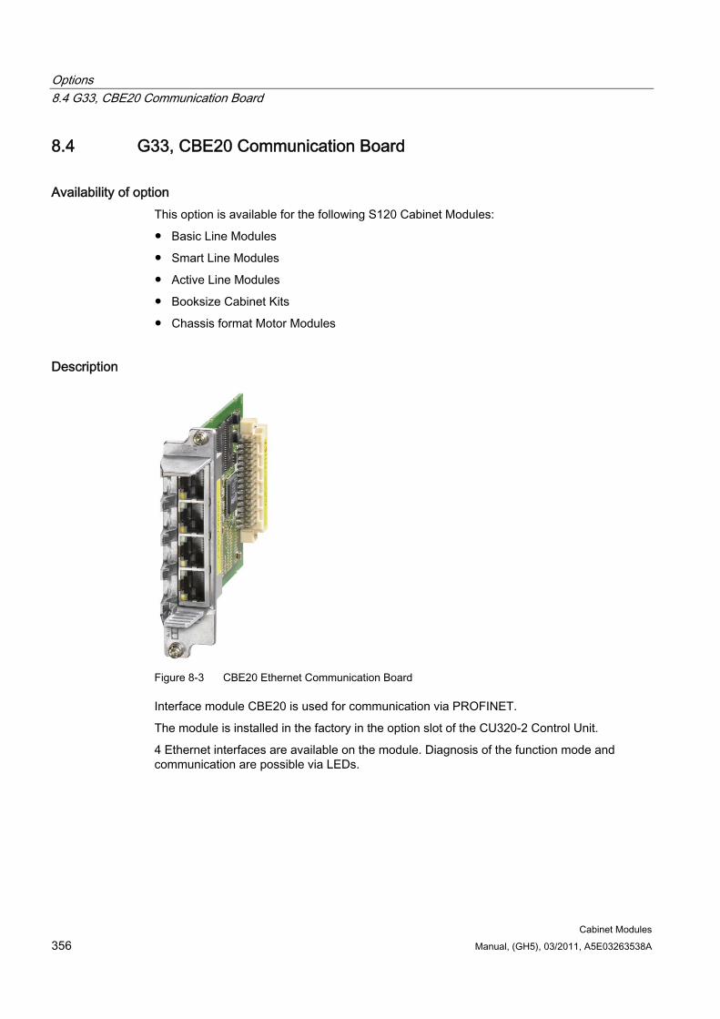
Options 8.4 G33, CBE20 Communication Board
Cabinet Modules 356 Manual, (GH5), 03/2011, A5E03263538A
8.4 G33, CBE20 Communication Board
Availability of option This option is available for the following S120 Cabinet Modules:
Basic Line Modules
Smart Line Modules
Active Line Modules
Booksize Cabinet Kits
Chassis format Motor Modules
Description
Figure 8-3 CBE20 Ethernet Communication Board
Interface module CBE20 is used for communication via PROFINET.
The module is installed in the factory in the option slot of the CU320-2 Control Unit.
4 Ethernet interfaces are available on the module. Diagnosis of the function mode and communication are possible via LEDs.
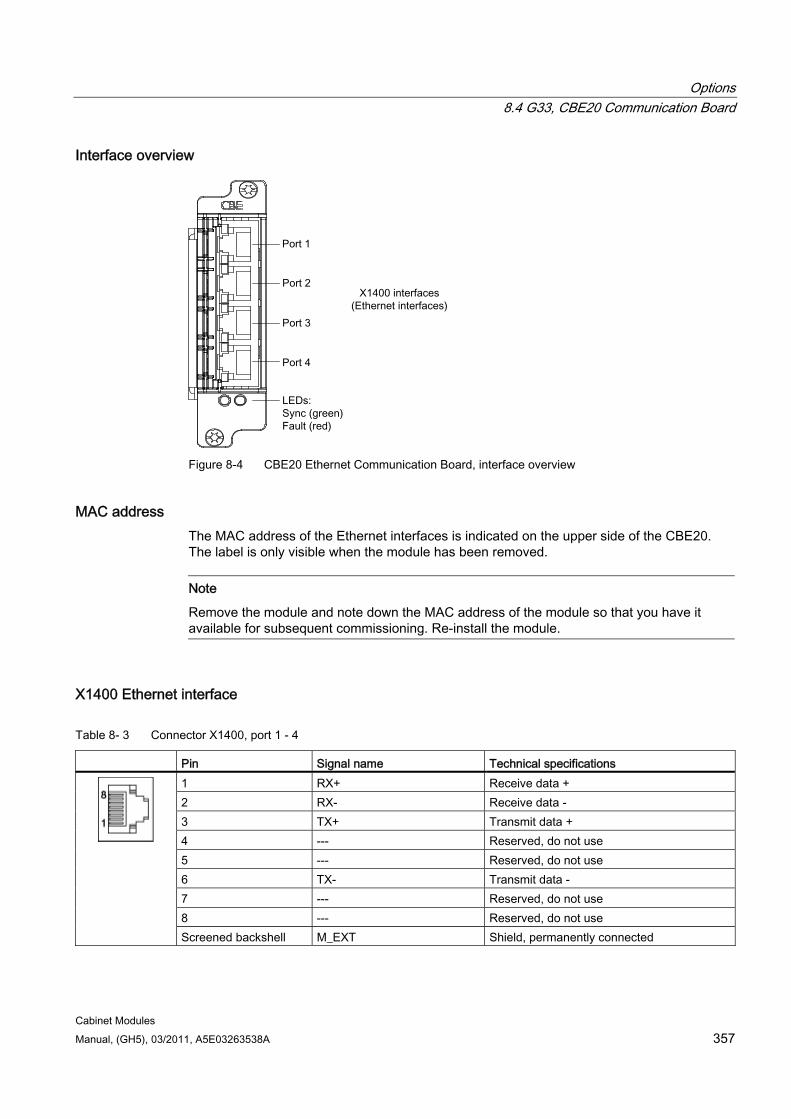
Options 8.4 G33, CBE20 Communication Board
Cabinet Modules Manual, (GH5), 03/2011, A5E03263538A 357
Interface overview
Figure 8-4 CBE20 Ethernet Communication Board, interface overview
MAC address The MAC address of the Ethernet interfaces is indicated on the upper side of the CBE20. The label is only visible when the module has been removed.
Note
Remove the module and note down the MAC address of the module so that you have it available for subsequent commissioning. Re-install the module.
X1400 Ethernet interface
Table 8- 3 Connector X1400, port 1 - 4
Pin Signal name Technical specifications 1 RX+ Receive data + 2 RX- Receive data - 3 TX+ Transmit data + 4 --- Reserved, do not use 5 --- Reserved, do not use 6 TX- Transmit data - 7 --- Reserved, do not use 8 --- Reserved, do not use
Screened backshell M_EXT Shield, permanently connected
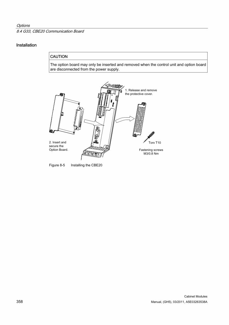
Options 8.4 G33, CBE20 Communication Board
Cabinet Modules 358 Manual, (GH5), 03/2011, A5E03263538A
Installation
CAUTION The option board may only be inserted and removed when the control unit and option board are disconnected from the power supply.
Figure 8-5 Installing the CBE20
Options 8.5 G55, customer terminal block
Cabinet Modules Manual, (GH5), 03/2011, A5E03263538A 359
8.5 G55, customer terminal block
8.5.1 General information
Availability of option This option is available for the following S120 Cabinet Modules:
Basic Line Modules
Smart Line Modules
Active Line Modules
Booksize Cabinet Kits
Chassis format Motor Modules
Note
The factory setting and description of the customer terminal block -X55 can be found in the circuit diagrams.
The location of the customer terminal block -X55 of the individual Cabinet Modules is documented in the layout diagrams.
The interfaces or customer terminal blocks are documented for the respective Cabinet Modules.
Description The customer terminal block- X55 (option G55) is used as a signal interface of the Cabinet Module to the I/O and consolidates and transfers a number of cabinet-internal signals to a central terminal block module in the lower area of the cabinet.
For options K90/K95, terminal blocks -X122 and -X132 are also fully assigned. (→ See Chapter, "Options" in Sections "K90, Control Unit CU320-2 PROFIBUS" / "K95, Control Unit CU320-2 PROFINET")
NOTICE Interfaces -X1, -X2, -X3 and -X4 are wired in the cabinet and are not available for customer connections!
If the customer terminal block is ever replaced, connectors -X1 and -X2 must not be interchanged! Otherwise, the "Safe Torque Off" and "Safe Stop 1" safety functions will malfunction.
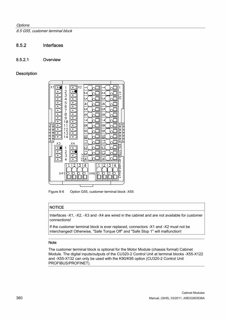
Options 8.5 G55, customer terminal block
Cabinet Modules 360 Manual, (GH5), 03/2011, A5E03263538A
8.5.2 Interfaces
8.5.2.1 Overview
Description
Figure 8-6 Option G55, customer terminal block -X55
NOTICE Interfaces -X1, -X2, -X3 and -X4 are wired in the cabinet and are not available for customer connections!
If the customer terminal block is ever replaced, connectors -X1 and -X2 must not be interchanged! Otherwise, "Safe Torque Off" and "Safe Stop 1" will malfunction!
Note
The customer terminal block is optional for the Motor Module (chassis format) Cabinet Module. The digital inputs/outputs of the CU320-2 Control Unit at terminal blocks -X55-X122 and -X55-X132 can only be used with the K90/K95 option (CU320-2 Control Unit PROFIBUS/PROFINET).
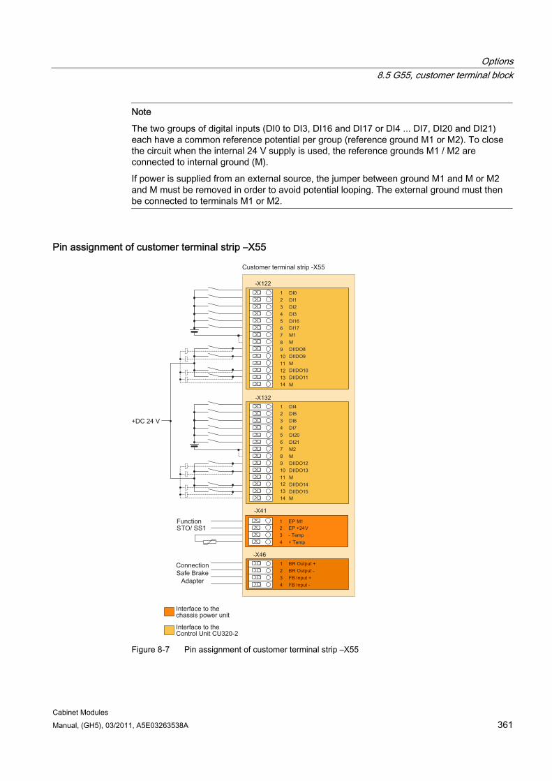
Options 8.5 G55, customer terminal block
Cabinet Modules Manual, (GH5), 03/2011, A5E03263538A 361
Note
The two groups of digital inputs (DI0 to DI3, DI16 and DI17 or DI4 ... DI7, DI20 and DI21) each have a common reference potential per group (reference ground M1 or M2). To close the circuit when the internal 24 V supply is used, the reference grounds M1 / M2 are connected to internal ground (M).
If power is supplied from an external source, the jumper between ground M1 and M or M2 and M must be removed in order to avoid potential looping. The external ground must then be connected to terminals M1 or M2.
Pin assignment of customer terminal strip –X55
Interface to the chassis power unit
Customer terminal strip -X55
Interface to the Control Unit CU320-2
Function
Connection Safe Brake
Adapter
-X132
-X122
-X41
1 DI02 DI13 DI24 DI35 DI16
DI17M1
6
M7
DI/DO88
DI/DO99
M10
DI/DO1011
DI/DO1112
M1314
1 DI42 DI53 DI64 DI
DI20DI21
75
M26
M7
DI/DO128
DI/DO139
M10
DI/DO1411
DI/DO1512
M1314
-X461 BR Output +2 BR Output -3 FB Input +4 FB Input -
STO/ SS11 EP M12 EP +24
+DC 24 V
V3 - Temp4 + Temp
Figure 8-7 Pin assignment of customer terminal strip –X55
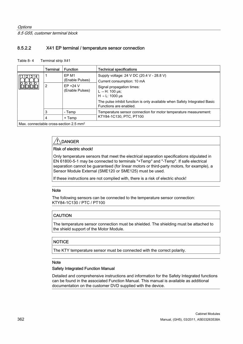
Options 8.5 G55, customer terminal block
Cabinet Modules 362 Manual, (GH5), 03/2011, A5E03263538A
8.5.2.2 X41 EP terminal / temperature sensor connection
Table 8- 4 Terminal strip X41
Terminal Function Technical specifications 1 EP M1
(Enable Pulses) 2 EP +24 V
(Enable Pulses)
Supply voltage: 24 V DC (20.4 V - 28.8 V) Current consumption: 10 mA Signal propagation times: L → H: 100 μs; H → L: 1000 μs The pulse inhibit function is only available when Safety Integrated Basic Functions are enabled.
3 - Temp
4 + Temp Temperature sensor connection for motor temperature measurement: KTY84-1C130, PTC, PT100
Max. connectable cross-section 2.5 mm2
DANGER Risk of electric shock!
Only temperature sensors that meet the electrical separation specifications stipulated in EN 61800-5-1 may be connected to terminals "+Temp" and "-Temp". If safe electrical separation cannot be guaranteed (for linear motors or third-party motors, for example), a Sensor Module External (SME120 or SME125) must be used.
If these instructions are not complied with, there is a risk of electric shock!
Note
The following sensors can be connected to the temperature sensor connection: KTY84-1C130 / PTC / PT100
CAUTION The temperature sensor connection must be shielded. The shielding must be attached to the shield support of the Motor Module.
NOTICE The KTY temperature sensor must be connected with the correct polarity.
Note Safety Integrated Function Manual
Detailed and comprehensive instructions and information for the Safety Integrated functions can be found in the associated Function Manual. This manual is available as additional documentation on the customer DVD supplied with the device.
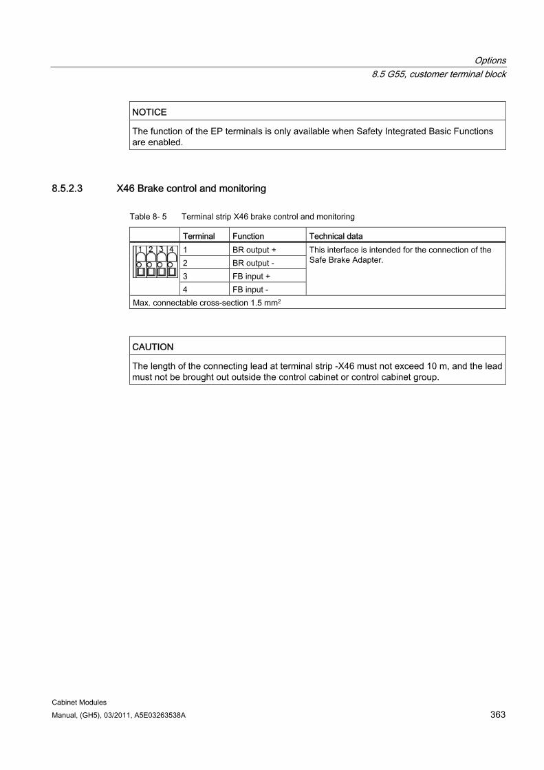
Options 8.5 G55, customer terminal block
Cabinet Modules Manual, (GH5), 03/2011, A5E03263538A 363
NOTICE The function of the EP terminals is only available when Safety Integrated Basic Functions are enabled.
8.5.2.3 X46 Brake control and monitoring
Table 8- 5 Terminal strip X46 brake control and monitoring
Terminal Function Technical data 1 BR output + 2 BR output - 3 FB input + 4 FB input -
This interface is intended for the connection of the Safe Brake Adapter.
Max. connectable cross-section 1.5 mm2
CAUTION The length of the connecting lead at terminal strip -X46 must not exceed 10 m, and the lead must not be brought out outside the control cabinet or control cabinet group.
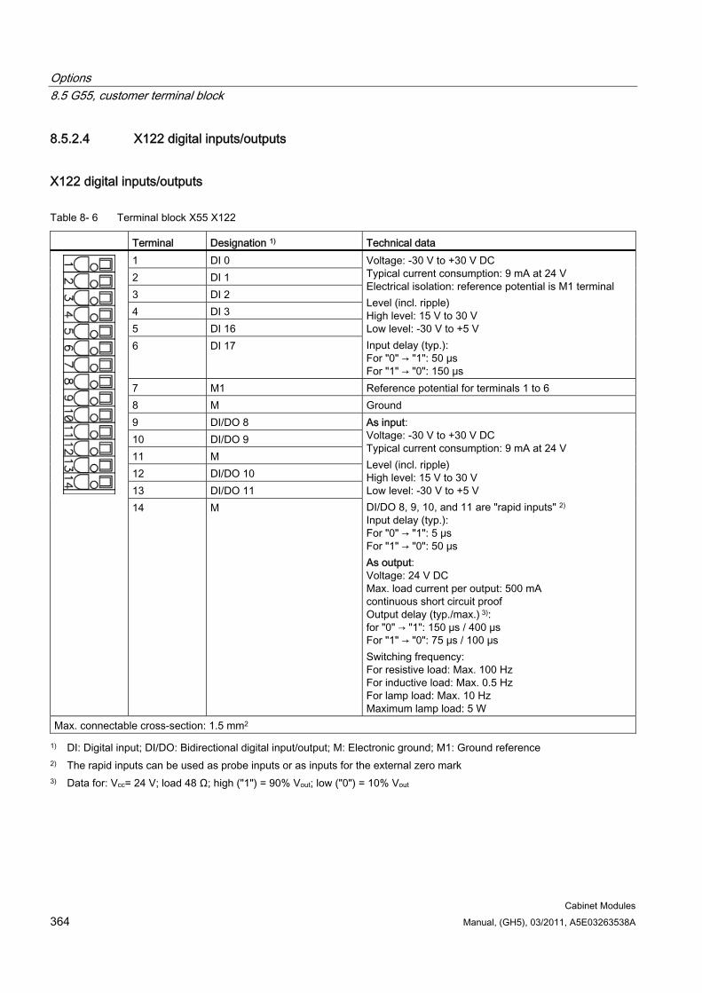
Options 8.5 G55, customer terminal block
Cabinet Modules 364 Manual, (GH5), 03/2011, A5E03263538A
8.5.2.4 X122 digital inputs/outputs
X122 digital inputs/outputs
Table 8- 6 Terminal block X55 X122
Terminal Designation 1) Technical data 1 DI 0 2 DI 1 3 DI 2 4 DI 3 5 DI 16 6 DI 17
Voltage: -30 V to +30 V DC Typical current consumption: 9 mA at 24 V Electrical isolation: reference potential is M1 terminal Level (incl. ripple) High level: 15 V to 30 V Low level: -30 V to +5 V Input delay (typ.): For "0" → "1": 50 μs For "1" → "0": 150 μs
7 M1 Reference potential for terminals 1 to 6 8 M Ground 9 DI/DO 8 10 DI/DO 9 11 M 12 DI/DO 10 13 DI/DO 11 14 M
As input: Voltage: -30 V to +30 V DC Typical current consumption: 9 mA at 24 V Level (incl. ripple) High level: 15 V to 30 V Low level: -30 V to +5 V DI/DO 8, 9, 10, and 11 are "rapid inputs" 2)
Input delay (typ.): For "0" → "1": 5 μs For "1" → "0": 50 μs As output: Voltage: 24 V DC Max. load current per output: 500 mA continuous short circuit proof Output delay (typ./max.) 3): for "0" → "1": 150 μs / 400 μs For "1" → "0": 75 μs / 100 μs Switching frequency: For resistive load: Max. 100 Hz For inductive load: Max. 0.5 Hz For lamp load: Max. 10 Hz Maximum lamp load: 5 W
Max. connectable cross-section: 1.5 mm2
1) DI: Digital input; DI/DO: Bidirectional digital input/output; M: Electronic ground; M1: Ground reference 2) The rapid inputs can be used as probe inputs or as inputs for the external zero mark 3) Data for: Vcc= 24 V; load 48 Ω; high ("1") = 90% Vout; low ("0") = 10% Vout

Options 8.5 G55, customer terminal block
Cabinet Modules Manual, (GH5), 03/2011, A5E03263538A 365
NOTICE An open input is interpreted as "low".
To enable the digital inputs (DI) to function, terminal M1 must be connected.
This is achieved by: 1. Providing the ground reference of the digital inputs, or 2. a jumper to terminal M.
Notice! This removes the electrical isolation for these digital inputs.
Note
If a momentary interruption in the voltage occurs in the 24 V supply, the digital outputs are deactivated until the interruption has been rectified.
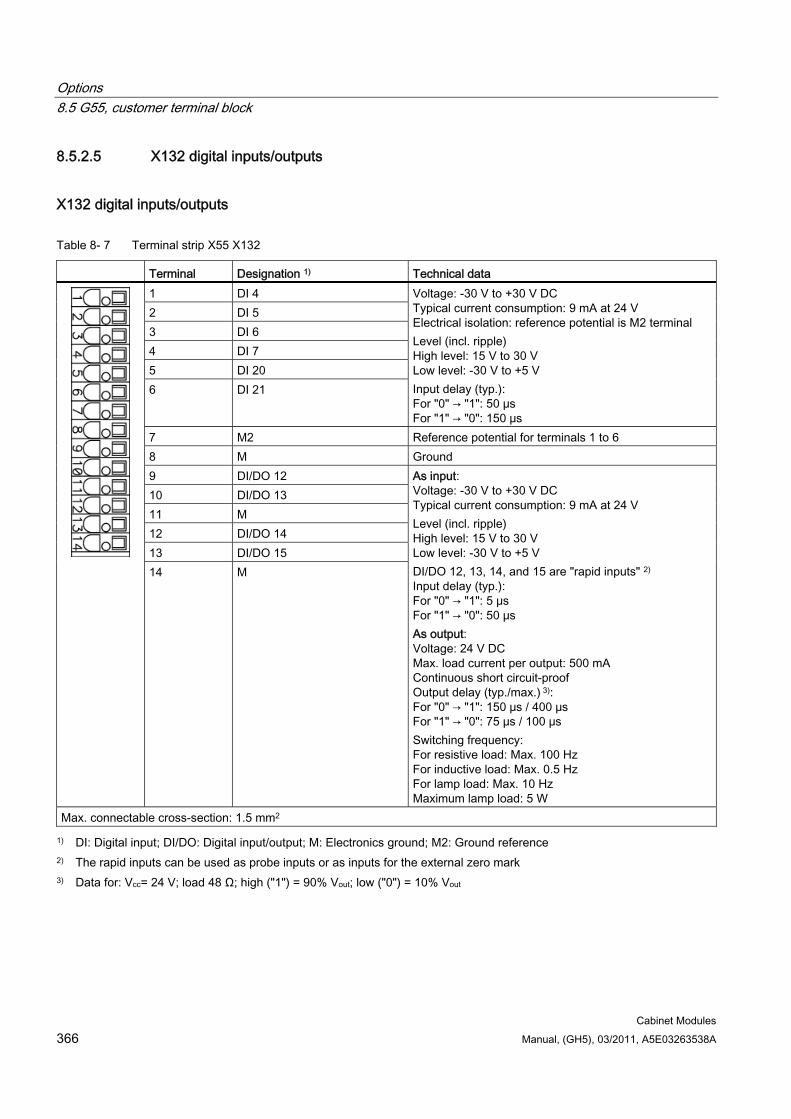
Options 8.5 G55, customer terminal block
Cabinet Modules 366 Manual, (GH5), 03/2011, A5E03263538A
8.5.2.5 X132 digital inputs/outputs
X132 digital inputs/outputs
Table 8- 7 Terminal strip X55 X132
Terminal Designation 1) Technical data 1 DI 4 2 DI 5 3 DI 6 4 DI 7 5 DI 20 6 DI 21
Voltage: -30 V to +30 V DC Typical current consumption: 9 mA at 24 V Electrical isolation: reference potential is M2 terminal Level (incl. ripple) High level: 15 V to 30 V Low level: -30 V to +5 V Input delay (typ.): For "0" → "1": 50 μs For "1" → "0": 150 μs
7 M2 Reference potential for terminals 1 to 6 8 M Ground 9 DI/DO 12 10 DI/DO 13 11 M 12 DI/DO 14 13 DI/DO 15 14 M
As input: Voltage: -30 V to +30 V DC Typical current consumption: 9 mA at 24 V Level (incl. ripple) High level: 15 V to 30 V Low level: -30 V to +5 V DI/DO 12, 13, 14, and 15 are "rapid inputs" 2) Input delay (typ.): For "0" → "1": 5 μs For "1" → "0": 50 μs As output: Voltage: 24 V DC Max. load current per output: 500 mA Continuous short circuit-proof Output delay (typ./max.) 3): For "0" → "1": 150 μs / 400 μs For "1" → "0": 75 μs / 100 μs Switching frequency: For resistive load: Max. 100 Hz For inductive load: Max. 0.5 Hz For lamp load: Max. 10 Hz Maximum lamp load: 5 W
Max. connectable cross-section: 1.5 mm2
1) DI: Digital input; DI/DO: Digital input/output; M: Electronics ground; M2: Ground reference 2) The rapid inputs can be used as probe inputs or as inputs for the external zero mark 3) Data for: Vcc= 24 V; load 48 Ω; high ("1") = 90% Vout; low ("0") = 10% Vout

Options 8.5 G55, customer terminal block
Cabinet Modules Manual, (GH5), 03/2011, A5E03263538A 367
NOTICE An open input is interpreted as "low".
To enable the digital inputs (DI) to function, terminal M2 must be connected.
This is achieved by: 1. Providing the ground reference of the digital inputs, or 2. a jumper to terminal M.
Notice! This removes the electrical isolation for these digital inputs.
Note
If a momentary interruption in the voltage occurs in the 24 V supply, the digital outputs are deactivated until the interruption has been rectified.
Options 8.6 G56, contactor feedback signal, S120 Cabinet Modules
Cabinet Modules 368 Manual, (GH5), 03/2011, A5E03263538A
8.6 G56, contactor feedback signal, S120 Cabinet Modules
Availability of option This option is available for the following S120 cabinet modules:
Basic Line Modules
Smart Line Modules
Active Line Modules
Chassis format Motor Modules
Description The contactor feedback signal option is used to directly monitor the pre-charging and bypass contactor in the power unit. The contactor feedback signal cable from the contactors to the Control Interface Module is installed in the factory.
Activation The monitoring is activated using the following parameters:
p0255.0 = monitoring time for the pre-charging contactor (factory setting = 0, max. 6500 ms)
p0255.1 = monitoring time for the bypass contactor (factory setting = 0, max. 6500 ms)
Fault messages F30060 (A) pre-charging contactor status monitoring
F30061 (A) bypass contactor status monitoring
Options 8.7 K01 to K05, safety license for 1 to 5 axes
Cabinet Modules Manual, (GH5), 03/2011, A5E03263538A 369
8.7 K01 to K05, safety license for 1 to 5 axes
Availability of option This option is available for the following S120 Cabinet Modules:
Booksize Cabinet Kits
Chassis format Motor Modules
Description The Safety Integrated Basic functions do not require a license. A license is, however, required for each axis with safety functions in the case of Safety Integrated Extended functions. It is irrelevant which safety functions are used and how many.
In this case, option K01 is for 1 axis, option K02 for 2 axes etc. - up to option K05 for 5 axes.
K01: Safety license for 1 axis
K02: Safety license for 2 axes
K03: Safety license for 3 axes
K04: Safety license for 4 axes
K05: Safety license for 5 axes
Note
Presently, a maximum of 5 safety axes with Safety Integrated Extended functions are possible on a Control Unit CU320-2.
Licenses The required licenses can be optionally ordered together with the CompactFlash Card.
Subsequent licensing is realized in the Internet using the "WEB License Manager" by generating a license key: http://www.siemens.com/automation/license
Note
The generation of the license key is described in detail in the SINAMICS S120 Function Manual, Chapter "Basics of the drive system" under "Licensing".
Options 8.7 K01 to K05, safety license for 1 to 5 axes
Cabinet Modules 370 Manual, (GH5), 03/2011, A5E03263538A
Activation The associated license key is entered into parameter p9920 in the ASCII code. The license key is activated using parameter p9921 = 1.
Diagnostics An insufficient license is indicated via the following alarm and LED:
Alarm A13000 → License not sufficient
LED READY → Flashes green/red at 0.5 Hz
Note Safety Integrated Function Manual
Detailed and comprehensive instructions and information for the Safety Integrated functions can be found in the associated Function Manual. This manual is available as additional documentation on the customer DVD supplied with the device.
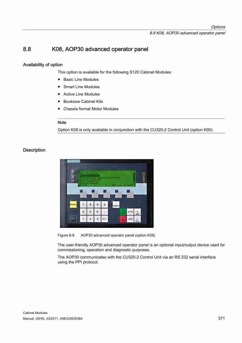
Options 8.8 K08, AOP30 advanced operator panel
Cabinet Modules Manual, (GH5), 03/2011, A5E03263538A 371
8.8 K08, AOP30 advanced operator panel
Availability of option This option is available for the following S120 Cabinet Modules:
Basic Line Modules
Smart Line Modules
Active Line Modules
Booksize Cabinet Kits
Chassis format Motor Modules
Note
Option K08 is only available in conjunction with the CU320-2 Control Unit (option K90).
Description
Figure 8-8 AOP30 advanced operator panel (option K08)
The user-friendly AOP30 advanced operator panel is an optional input/output device used for commissioning, operation and diagnostic purposes.
The AOP30 communicates with the CU320-2 Control Unit via an RS 232 serial interface using the PPI protocol.
Options 8.8 K08, AOP30 advanced operator panel
Cabinet Modules 372 Manual, (GH5), 03/2011, A5E03263538A
Features Display with green backlighting (resolution: 240 x 64 pixels)
26-key keypad
RS 232 interface
Time and date memory powered by internal battery backup
4 LEDs indicate the operating condition of the drive unit: RUN, green ALARM, yellow FAULT, red LOCAL/REMOTE, green
Note Additional documents
Detailed and comprehensive instructions and information for the AOP30 Advanced Operator Panel can be found in the relevant operating instructions. These operating instructions are available as additional documentation on the customer DVD supplied with the device.
→ See additional documentation "SINAMICS S120 Cabinet Module AOP30"
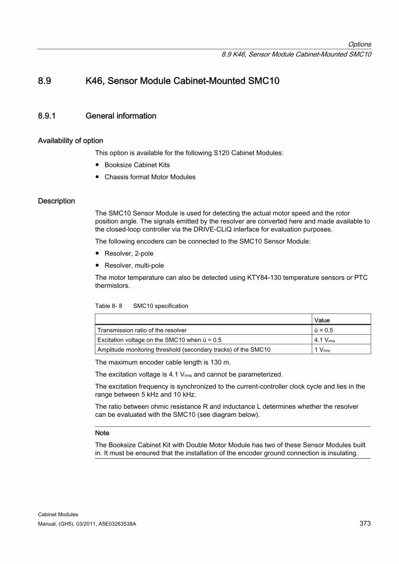
Options 8.9 K46, Sensor Module Cabinet-Mounted SMC10
Cabinet Modules Manual, (GH5), 03/2011, A5E03263538A 373
8.9 K46, Sensor Module Cabinet-Mounted SMC10
8.9.1 General information
Availability of option This option is available for the following S120 Cabinet Modules:
Booksize Cabinet Kits
Chassis format Motor Modules
Description The SMC10 Sensor Module is used for detecting the actual motor speed and the rotor position angle. The signals emitted by the resolver are converted here and made available to the closed-loop controller via the DRIVE-CLiQ interface for evaluation purposes.
The following encoders can be connected to the SMC10 Sensor Module:
Resolver, 2-pole
Resolver, multi-pole
The motor temperature can also be detected using KTY84-130 temperature sensors or PTC thermistors.
Table 8- 8 SMC10 specification
Value Transmission ratio of the resolver ü = 0.5 Excitation voltage on the SMC10 when ü = 0.5 4.1 Vrms Amplitude monitoring threshold (secondary tracks) of the SMC10 1 Vrms
The maximum encoder cable length is 130 m.
The excitation voltage is 4.1 Vrms and cannot be parameterized.
The excitation frequency is synchronized to the current-controller clock cycle and lies in the range between 5 kHz and 10 kHz.
The ratio between ohmic resistance R and inductance L determines whether the resolver can be evaluated with the SMC10 (see diagram below).
Note
The Booksize Cabinet Kit with Double Motor Module has two of these Sensor Modules built in. It must be ensured that the installation of the encoder ground connection is insulating.
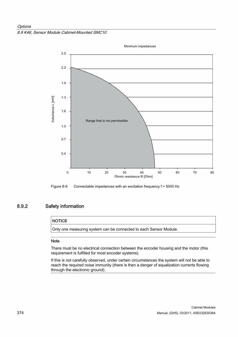
Options 8.9 K46, Sensor Module Cabinet-Mounted SMC10
Cabinet Modules 374 Manual, (GH5), 03/2011, A5E03263538A
Figure 8-9 Connectable impedances with an excitation frequency f = 5000 Hz
8.9.2 Safety information
NOTICE Only one measuring system can be connected to each Sensor Module.
Note
There must be no electrical connection between the encoder housing and the motor (this requirement is fulfilled for most encoder systems).
If this is not carefully observed, under certain circumstances the system will not be able to reach the required noise immunity (there is then a danger of equalization currents flowing through the electronic ground).
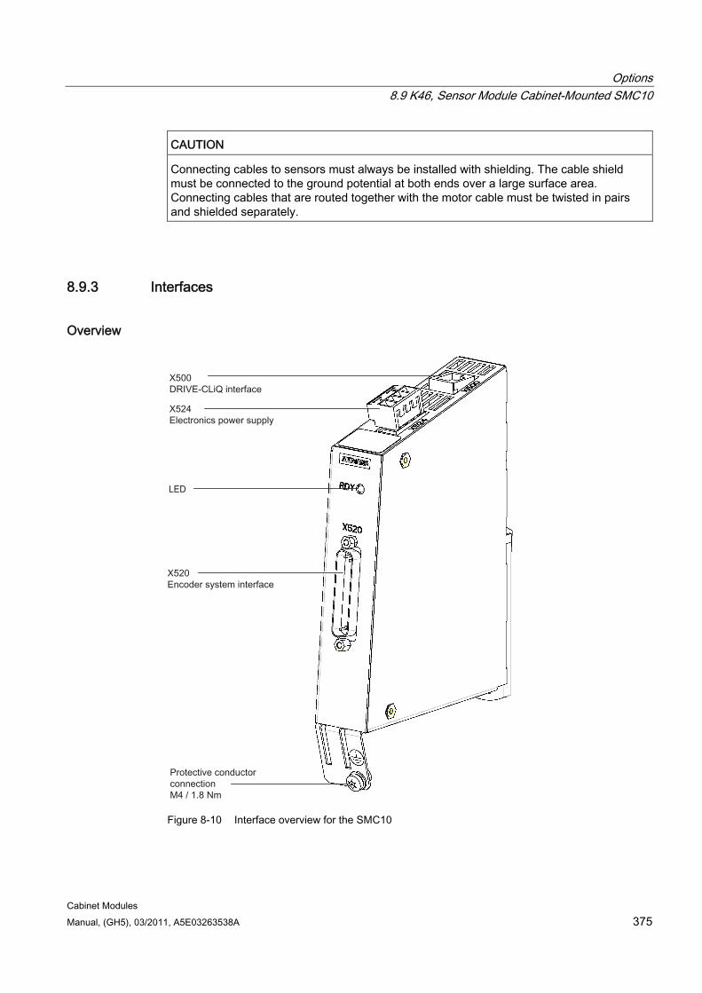
Options 8.9 K46, Sensor Module Cabinet-Mounted SMC10
Cabinet Modules Manual, (GH5), 03/2011, A5E03263538A 375
CAUTION Connecting cables to sensors must always be installed with shielding. The cable shield must be connected to the ground potential at both ends over a large surface area. Connecting cables that are routed together with the motor cable must be twisted in pairs and shielded separately.
8.9.3 Interfaces
Overview
Figure 8-10 Interface overview for the SMC10
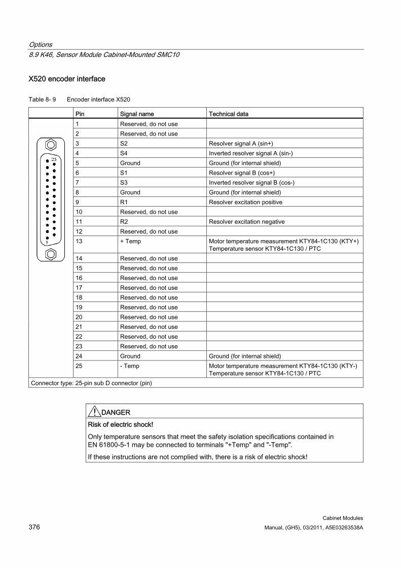
Options 8.9 K46, Sensor Module Cabinet-Mounted SMC10
Cabinet Modules 376 Manual, (GH5), 03/2011, A5E03263538A
X520 encoder interface
Table 8- 9 Encoder interface X520
Pin Signal name Technical data 1 Reserved, do not use 2 Reserved, do not use 3 S2 Resolver signal A (sin+) 4 S4 Inverted resolver signal A (sin-) 5 Ground Ground (for internal shield) 6 S1 Resolver signal B (cos+) 7 S3 Inverted resolver signal B (cos-) 8 Ground Ground (for internal shield) 9 R1 Resolver excitation positive 10 Reserved, do not use 11 R2 Resolver excitation negative 12 Reserved, do not use 13 + Temp Motor temperature measurement KTY84-1C130 (KTY+)
Temperature sensor KTY84-1C130 / PTC 14 Reserved, do not use 15 Reserved, do not use 16 Reserved, do not use 17 Reserved, do not use 18 Reserved, do not use 19 Reserved, do not use 20 Reserved, do not use 21 Reserved, do not use 22 Reserved, do not use 23 Reserved, do not use 24 Ground Ground (for internal shield)
25 - Temp Motor temperature measurement KTY84-1C130 (KTY-)Temperature sensor KTY84-1C130 / PTC
Connector type: 25-pin sub D connector (pin)
DANGER Risk of electric shock!
Only temperature sensors that meet the safety isolation specifications contained in EN 61800-5-1 may be connected to terminals "+Temp" and "-Temp".
If these instructions are not complied with, there is a risk of electric shock!
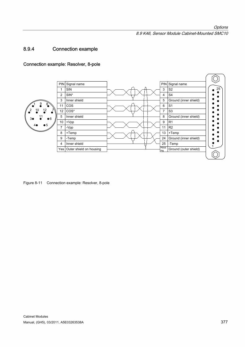
Options 8.9 K46, Sensor Module Cabinet-Mounted SMC10
Cabinet Modules Manual, (GH5), 03/2011, A5E03263538A 377
8.9.4 Connection example
Connection example: Resolver, 8-pole
Figure 8-11 Connection example: Resolver, 8-pole
Options 8.10 K48, Sensor Module Cabinet-Mounted SMC20
Cabinet Modules 378 Manual, (GH5), 03/2011, A5E03263538A
8.10 K48, Sensor Module Cabinet-Mounted SMC20
8.10.1 General information
Availability of option This option is available for the following S120 Cabinet Modules:
Booksize Cabinet Kits
Chassis format Motor Modules
Description The SMC20 Sensor Module is used to simultaneously detect the actual motor speed and the path length. The signals emitted by the incremental encoder are converted here and made available to the closed-loop controller via the DRIVE-CLiQ interface for evaluation purposes.
The following encoders can be connected to the SMC20 Sensor Module:
Incremental encoder sin/cos 1 Vpp
EnDat and SSI absolute encoders
The motor temperature can also be detected using KTY84-130 temperature sensors or PTC thermistors.
The maximum encoder cable length is 100 m.
Note
The Booksize Cabinet Kit with Double Motor Module has two of these encoder modules built in.
8.10.2 Safety information
NOTICE Only one measuring system can be connected to each Sensor Module.
Note
There must be no electrical connection between the measuring system housing and the measuring system electronics (this requirement is fulfilled for most encoder systems).
If this is not carefully observed, under certain circumstances the system will not be able to reach the required noise immunity (there is then a danger of equalization currents flowing through the electronic ground).
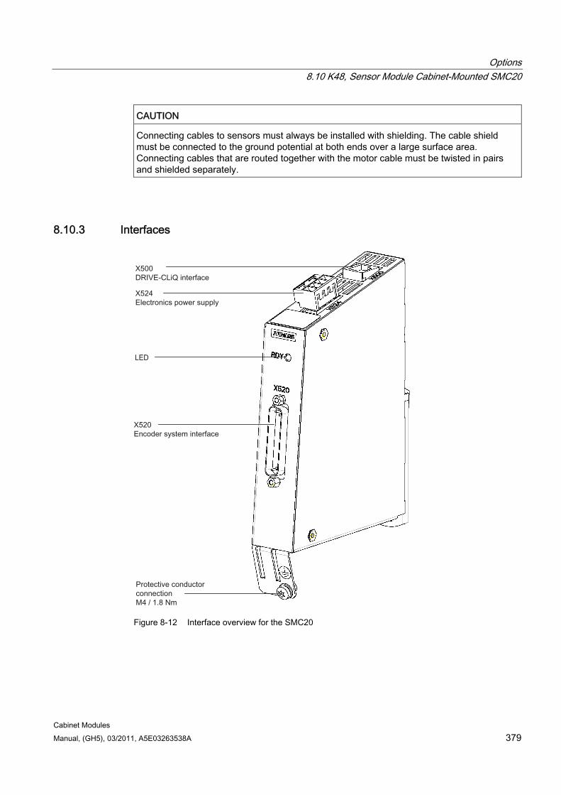
Options 8.10 K48, Sensor Module Cabinet-Mounted SMC20
Cabinet Modules Manual, (GH5), 03/2011, A5E03263538A 379
CAUTION Connecting cables to sensors must always be installed with shielding. The cable shield must be connected to the ground potential at both ends over a large surface area. Connecting cables that are routed together with the motor cable must be twisted in pairs and shielded separately.
8.10.3 Interfaces
Figure 8-12 Interface overview for the SMC20
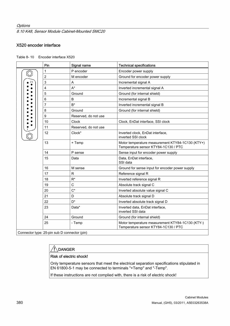
Options 8.10 K48, Sensor Module Cabinet-Mounted SMC20
Cabinet Modules 380 Manual, (GH5), 03/2011, A5E03263538A
X520 encoder interface
Table 8- 10 Encoder interface X520
Pin Signal name Technical specifications 1 P encoder Encoder power supply 2 M encoder Ground for encoder power supply 3 A Incremental signal A 4 A* Inverted incremental signal A 5 Ground Ground (for internal shield) 6 B Incremental signal B 7 B* Inverted incremental signal B 8 Ground Ground (for internal shield) 9 Reserved, do not use 10 Clock Clock, EnDat interface, SSI clock 11 Reserved, do not use 12 Clock*
Inverted clock, EnDat interface, inverted SSI clock
13 + Temp Motor temperature measurement KTY84-1C130 (KTY+) Temperature sensor KTY84-1C130 / PTC
14 P sense Sense input for encoder power supply 15 Data Data, EnDat interface,
SSI data 16 M sense Ground for sense input for encoder power supply 17 R Reference signal R 18 R* Inverted reference signal R 19 C Absolute track signal C 20 C* Inverted absolute value signal C 21 D Absolute track signal D 22 D* Inverted absolute track signal D 23 Data* Inverted data, EnDat interface,
inverted SSI data 24 Ground Ground (for internal shield)
25 - Temp Motor temperature measurement KTY84-1C130 (KTY-) Temperature sensor KTY84-1C130 / PTC
Connector type: 25-pin sub D connector (pin)
DANGER Risk of electric shock!
Only temperature sensors that meet the electrical separation specifications stipulated in EN 61800-5-1 may be connected to terminals "+Temp" and "-Temp".
If these instructions are not complied with, there is a risk of electric shock!
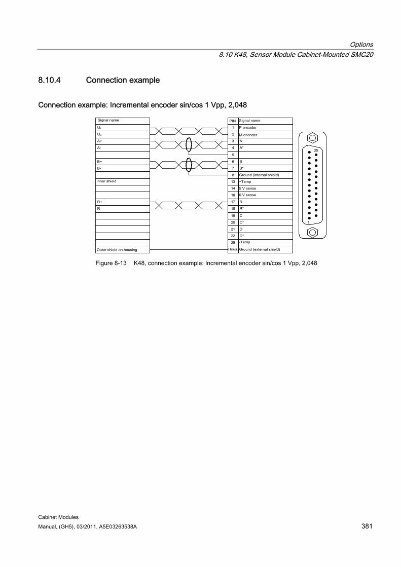
Options 8.10 K48, Sensor Module Cabinet-Mounted SMC20
Cabinet Modules Manual, (GH5), 03/2011, A5E03263538A 381
8.10.4 Connection example
Connection example: Incremental encoder sin/cos 1 Vpp, 2,048
Figure 8-13 K48, connection example: Incremental encoder sin/cos 1 Vpp, 2,048
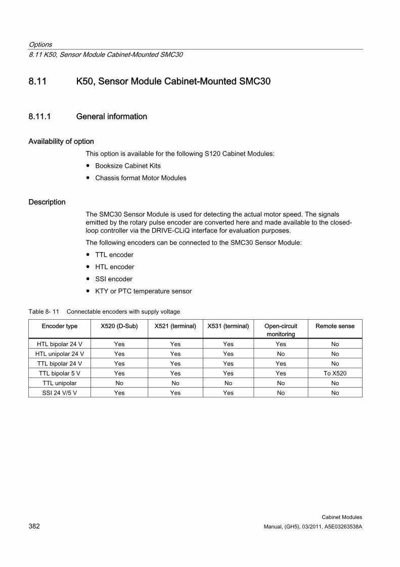
Options 8.11 K50, Sensor Module Cabinet-Mounted SMC30
Cabinet Modules 382 Manual, (GH5), 03/2011, A5E03263538A
8.11 K50, Sensor Module Cabinet-Mounted SMC30
8.11.1 General information
Availability of option This option is available for the following S120 Cabinet Modules:
Booksize Cabinet Kits
Chassis format Motor Modules
Description The SMC30 Sensor Module is used for detecting the actual motor speed. The signals emitted by the rotary pulse encoder are converted here and made available to the closed-loop controller via the DRIVE-CLiQ interface for evaluation purposes.
The following encoders can be connected to the SMC30 Sensor Module:
TTL encoder
HTL encoder
SSI encoder
KTY or PTC temperature sensor
Table 8- 11 Connectable encoders with supply voltage
Encoder type X520 (D-Sub) X521 (terminal) X531 (terminal) Open-circuit monitoring
Remote sense
HTL bipolar 24 V Yes Yes Yes Yes No HTL unipolar 24 V Yes Yes Yes No No TTL bipolar 24 V Yes Yes Yes Yes No TTL bipolar 5 V Yes Yes Yes Yes To X520
TTL unipolar No No No No No SSI 24 V/5 V Yes Yes Yes No No
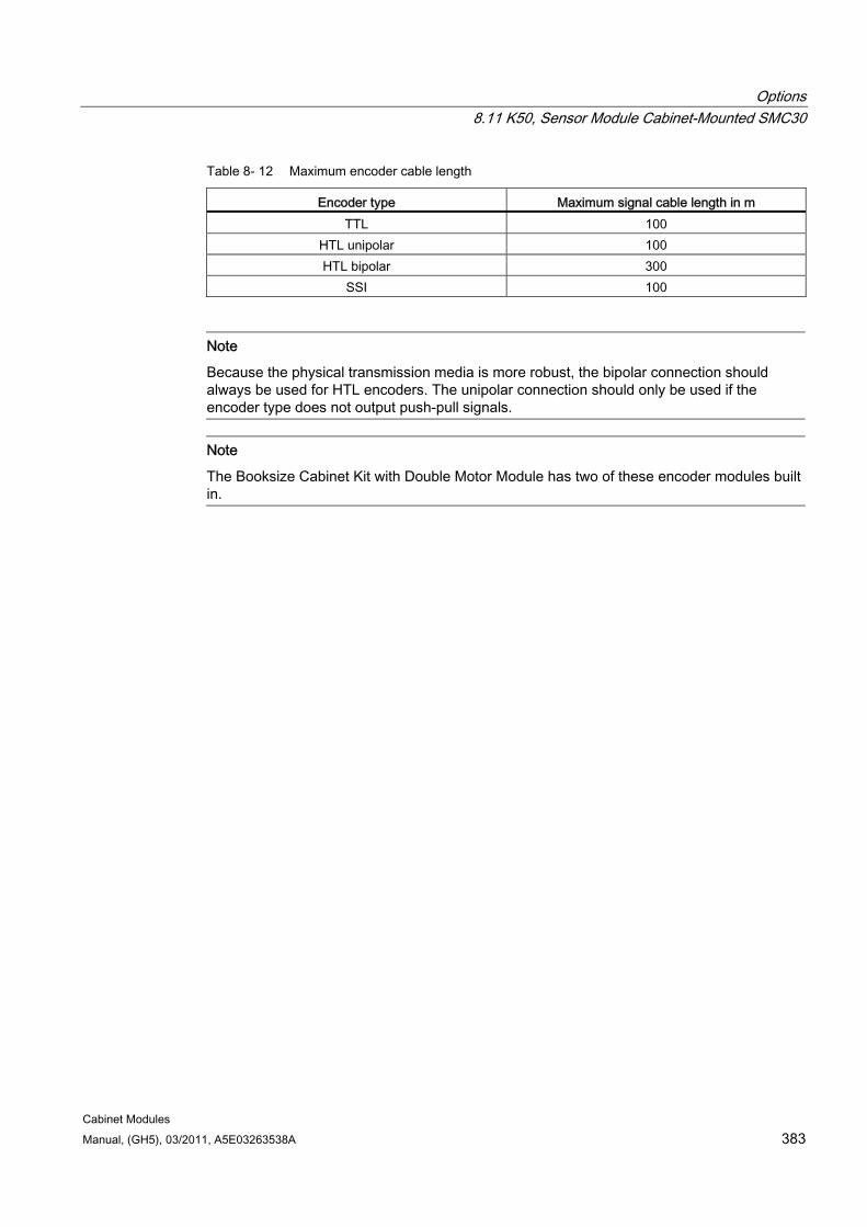
Options 8.11 K50, Sensor Module Cabinet-Mounted SMC30
Cabinet Modules Manual, (GH5), 03/2011, A5E03263538A 383
Table 8- 12 Maximum encoder cable length
Encoder type Maximum signal cable length in m TTL 100
HTL unipolar 100 HTL bipolar 300
SSI 100
Note
Because the physical transmission media is more robust, the bipolar connection should always be used for HTL encoders. The unipolar connection should only be used if the encoder type does not output push-pull signals.
Note
The Booksize Cabinet Kit with Double Motor Module has two of these encoder modules built in.
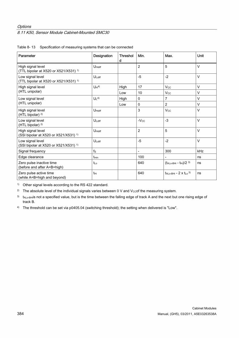
Options 8.11 K50, Sensor Module Cabinet-Mounted SMC30
Cabinet Modules 384 Manual, (GH5), 03/2011, A5E03263538A
Table 8- 13 Specification of measuring systems that can be connected
Parameter Designation Threshold
Min. Max. Unit
High signal level (TTL bipolar at X520 or X521/X531) 1)
UHdiff 2 5 V
Low signal level (TTL bipolar at X520 or X521/X531) 1)
ULdiff -5 -2 V
High 17 VCC V High signal level (HTL unipolar)
UH4) Low 10 VCC V High 0 7 V Low signal level
(HTL unipolar) UL4)
Low 0 2 V High signal level (HTL bipolar) 2)
UHdiff 3 VCC V
Low signal level (HTL bipolar) 2)
ULdiff -VCC -3 V
High signal level (SSI bipolar at X520 or X521/X531) 1)
UHdiff 2 5 V
Low signal level (SSI bipolar at X520 or X521/X531) 1)
ULdiff -5 -2 V
Signal frequency fS - 300 kHz Edge clearance tmin 100 - ns Zero pulse inactive time (before and after A=B=high)
tLo 640 (tALo-BHi - tHi)/2 3) ns
Zero pulse active time (while A=B=high and beyond)
tHi 640 tALo-BHi - 2 x tLo 3) ns
1) Other signal levels according to the RS 422 standard. 2) The absolute level of the individual signals varies between 0 V and VCCof the measuring system. 3) tALo-BHiis not a specified value, but is the time between the falling edge of track A and the next but one rising edge of
track B. 4) The threshold can be set via p0405.04 (switching threshold); the setting when delivered is "Low".
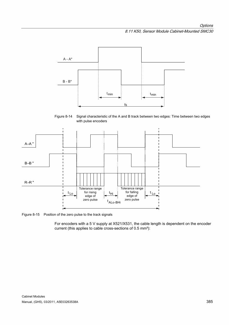
Options 8.11 K50, Sensor Module Cabinet-Mounted SMC30
Cabinet Modules Manual, (GH5), 03/2011, A5E03263538A 385
Figure 8-14 Signal characteristic of the A and B track between two edges: Time between two edges
with pulse encoders
Figure 8-15 Position of the zero pulse to the track signals
For encoders with a 5 V supply at X521/X531, the cable length is dependent on the encoder current (this applies to cable cross-sections of 0.5 mm²):
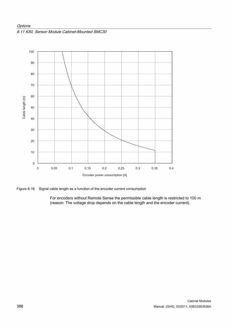
Options 8.11 K50, Sensor Module Cabinet-Mounted SMC30
Cabinet Modules 386 Manual, (GH5), 03/2011, A5E03263538A
Figure 8-16 Signal cable length as a function of the encoder current consumption
For encoders without Remote Sense the permissible cable length is restricted to 100 m (reason: The voltage drop depends on the cable length and the encoder current).
Options 8.11 K50, Sensor Module Cabinet-Mounted SMC30
Cabinet Modules Manual, (GH5), 03/2011, A5E03263538A 387
8.11.2 Safety information
NOTICE Only one measuring system can be connected to each Sensor Module.
Note
There must be no electrical connection between the measuring system housing and the measuring system electronics (this requirement is fulfilled for most encoder systems). If this is not carefully observed, under certain circumstances the system will not be able to reach the required noise immunity (there is then a danger of equalization currents flowing through the electronic ground).
CAUTION If screw terminals are used, the signal cable must be shielded and connected to the shield contact provided over a large surface area.
CAUTION Connecting cables to sensors must always be installed with shielding. The cable shield must be connected to the ground potential at both ends over a large surface area. Connecting cables that are routed together with the motor cable must be twisted in pairs and shielded separately.
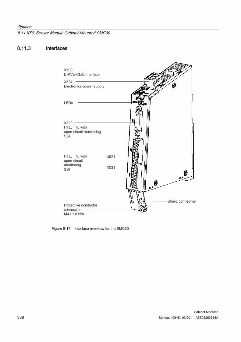
Options 8.11 K50, Sensor Module Cabinet-Mounted SMC30
Cabinet Modules 388 Manual, (GH5), 03/2011, A5E03263538A
8.11.3 Interfaces
Figure 8-17 Interface overview for the SMC30
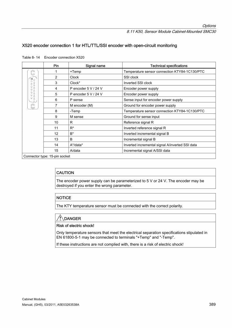
Options 8.11 K50, Sensor Module Cabinet-Mounted SMC30
Cabinet Modules Manual, (GH5), 03/2011, A5E03263538A 389
X520 encoder connection 1 for HTL/TTL/SSI encoder with open-circuit monitoring
Table 8- 14 Encoder connection X520
Pin Signal name Technical specifications 1 +Temp Temperature sensor connection KTY84-1C130/PTC 2 Clock SSI clock 3 Clock* Inverted SSI clock 4 P encoder 5 V / 24 V Encoder power supply 5 P encoder 5 V / 24 V Encoder power supply 6 P sense Sense input for encoder power supply 7 M encoder (M) Ground for encoder power supply 8 -Temp Temperature sensor connection KTY84-1C130/PTC 9 M sense Ground for sense input 10 R Reference signal R 11 R* Inverted reference signal R 12 B* Inverted incremental signal B 13 B Incremental signal B 14 A*/data* Inverted incremental signal A/inverted SSI data
15 A/data Incremental signal A/SSI data Connector type: 15-pin socket
CAUTION The encoder power supply can be parameterized to 5 V or 24 V. The encoder may be destroyed if you enter the wrong parameter.
NOTICE The KTY temperature sensor must be connected with the correct polarity.
DANGER Risk of electric shock!
Only temperature sensors that meet the electrical separation specifications stipulated in EN 61800-5-1 may be connected to terminals "+Temp" and "-Temp".
If these instructions are not complied with, there is a risk of electric shock!
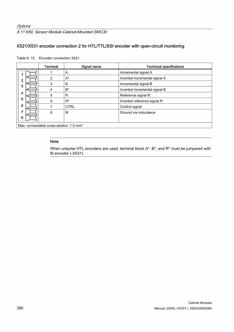
Options 8.11 K50, Sensor Module Cabinet-Mounted SMC30
Cabinet Modules 390 Manual, (GH5), 03/2011, A5E03263538A
X521/X531 encoder connection 2 for HTL/TTL/SSI encoder with open-circuit monitoring
Table 8- 15 Encoder connection X521
Terminal Signal name Technical specifications 1 A Incremental signal A 2 A* Inverted incremental signal A 3 B Incremental signal B 4 B* Inverted incremental signal B 5 R Reference signal R 6 R* Inverted reference signal R 7 CTRL Control signal
8 M Ground via inductance
Max. connectable cross-section: 1.5 mm²
Note
When unipolar HTL encoders are used, terminal block A*, B*, and R* must be jumpered with M encoder (-X531).
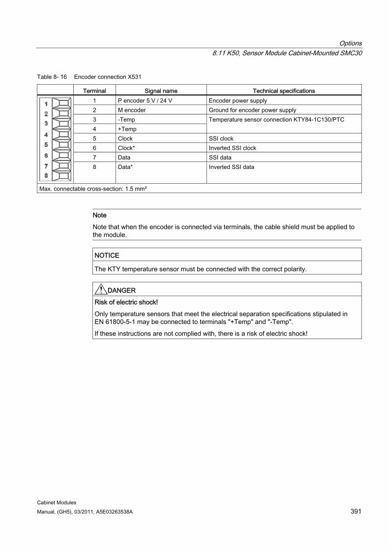
Options 8.11 K50, Sensor Module Cabinet-Mounted SMC30
Cabinet Modules Manual, (GH5), 03/2011, A5E03263538A 391
Table 8- 16 Encoder connection X531
Terminal Signal name Technical specifications 1 P encoder 5 V / 24 V Encoder power supply 2 M encoder Ground for encoder power supply 3 -Temp 4 +Temp
Temperature sensor connection KTY84-1C130/PTC
5 Clock SSI clock 6 Clock* Inverted SSI clock 7 Data SSI data
8 Data* Inverted SSI data
Max. connectable cross-section: 1.5 mm²
Note
Note that when the encoder is connected via terminals, the cable shield must be applied to the module.
NOTICE The KTY temperature sensor must be connected with the correct polarity.
DANGER Risk of electric shock!
Only temperature sensors that meet the electrical separation specifications stipulated in EN 61800-5-1 may be connected to terminals "+Temp" and "-Temp".
If these instructions are not complied with, there is a risk of electric shock!
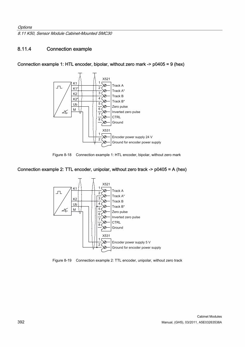
Options 8.11 K50, Sensor Module Cabinet-Mounted SMC30
Cabinet Modules 392 Manual, (GH5), 03/2011, A5E03263538A
8.11.4 Connection example
Connection example 1: HTL encoder, bipolar, without zero mark -> p0405 = 9 (hex)
Figure 8-18 Connection example 1: HTL encoder, bipolar, without zero mark
Connection example 2: TTL encoder, unipolar, without zero track -> p0405 = A (hex)
Figure 8-19 Connection example 2: TTL encoder, unipolar, without zero track
Options 8.12 K51, VSM10 Voltage Sensing Module Cabinet-Mounted
Cabinet Modules Manual, (GH5), 03/2011, A5E03263538A 393
8.12 K51, VSM10 Voltage Sensing Module Cabinet-Mounted
Availability of option This option is available for the following S120 Cabinet Modules:
Chassis format Motor Modules
Description Voltage recording module VSM10 is used to operate a permanent-field synchronous machine without encoder with the requirement for switching to a machine which is already running (flying restart function).
The terminals on the Voltage Sensing Module (-T1-B51) are pre-assigned in the factory and must not be changed by the customer.
To commission the function, the permanent-field synchronous machine without encoder must be input and "Flying restart" activated with p1200.
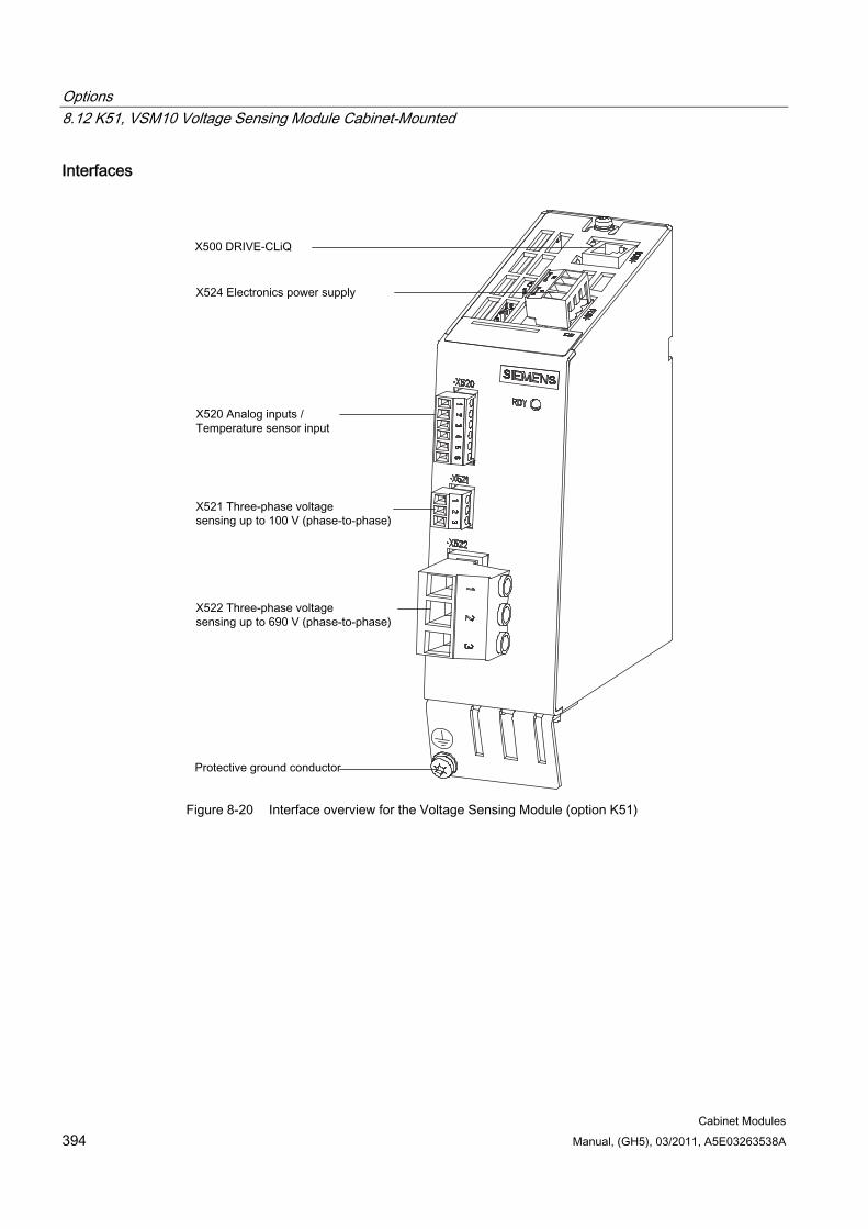
Options 8.12 K51, VSM10 Voltage Sensing Module Cabinet-Mounted
Cabinet Modules 394 Manual, (GH5), 03/2011, A5E03263538A
Interfaces
Figure 8-20 Interface overview for the Voltage Sensing Module (option K51)
Options 8.13 K76, auxiliary voltage generating unit in the Line Connection Module
Cabinet Modules Manual, (GH5), 03/2011, A5E03263538A 395
8.13 K76, auxiliary voltage generating unit in the Line Connection Module
Availability of option Line Connection Modules
Description Cabinet Modules require an auxiliary energy supply to function properly. This current demand must be included in the configuration and supplied from an external source. If an external supply is not possible, the required auxiliary voltages can be generated by an Auxiliary Power Supply Module.
Alternatively, option K76 can be selected to generate the auxiliary voltages in the Line Connection Module. This is particularly advisable for smaller device configurations.
The following auxiliary voltages are available:
2 AC 380 ... 480 V or 500 ... 690 V (poss. tap approx. 80 A)
230 V AC (poss. tap approx. 4 ... 6 A)
24 V DC (poss. tap approx. 20 ... 40 A)
The auxiliary voltages in the Line Connection Module can be connected to the auxiliary power module therefore supplying the complete cabinet group.
If the Cabinet Modules are delivered as factory-assembled transport units (option Y11), the electrical installation work has already been carried out. If the parts are delivered individually, the auxiliary power supply interface must be installed with 3 cables on site.
Depending on the version, the power loss is approx. 100 W.
Adapting the auxiliary power supply (-T10) A transformer is installed in the Line Connection Module (-T10) for the 230 V AC auxiliary power supply for the cabinet. The location of the transformer is indicated in the layout diagrams supplied.
When delivered, the taps are always set to the highest level. The line-side terminals of the transformer may need to be reconnected to the existing line voltage.
The line voltage assignments for making the appropriate setting on the transformer for the internal power supply are indicated in the following tables.
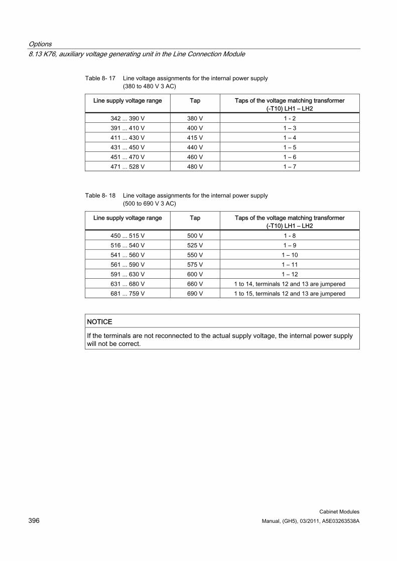
Options 8.13 K76, auxiliary voltage generating unit in the Line Connection Module
Cabinet Modules 396 Manual, (GH5), 03/2011, A5E03263538A
Table 8- 17 Line voltage assignments for the internal power supply (380 to 480 V 3 AC)
Line supply voltage range Tap Taps of the voltage matching transformer (-T10) LH1 – LH2
342 ... 390 V 380 V 1 - 2 391 ... 410 V 400 V 1 – 3 411 ... 430 V 415 V 1 – 4 431 ... 450 V 440 V 1 – 5 451 ... 470 V 460 V 1 – 6 471 ... 528 V 480 V 1 – 7
Table 8- 18 Line voltage assignments for the internal power supply (500 to 690 V 3 AC)
Line supply voltage range Tap Taps of the voltage matching transformer (-T10) LH1 – LH2
450 ... 515 V 500 V 1 - 8 516 ... 540 V 525 V 1 – 9 541 ... 560 V 550 V 1 – 10 561 ... 590 V 575 V 1 – 11 591 ... 630 V 600 V 1 – 12 631 ... 680 V 660 V 1 to 14, terminals 12 and 13 are jumpered 681 ... 759 V 690 V 1 to 15, terminals 12 and 13 are jumpered
NOTICE If the terminals are not reconnected to the actual supply voltage, the internal power supply will not be correct.
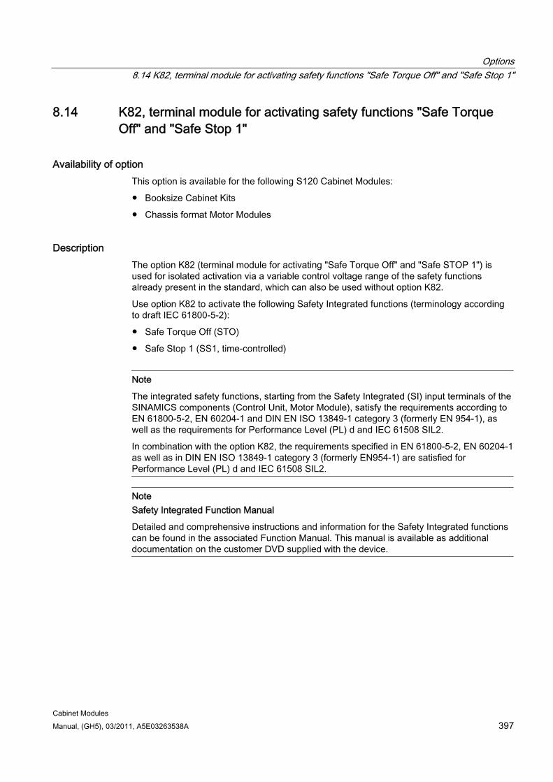
Options 8.14 K82, terminal module for activating safety functions "Safe Torque Off" and "Safe Stop 1"
Cabinet Modules Manual, (GH5), 03/2011, A5E03263538A 397
8.14 K82, terminal module for activating safety functions "Safe Torque Off" and "Safe Stop 1"
Availability of option This option is available for the following S120 Cabinet Modules:
Booksize Cabinet Kits
Chassis format Motor Modules
Description The option K82 (terminal module for activating "Safe Torque Off" and "Safe STOP 1") is used for isolated activation via a variable control voltage range of the safety functions already present in the standard, which can also be used without option K82.
Use option K82 to activate the following Safety Integrated functions (terminology according to draft IEC 61800-5-2):
Safe Torque Off (STO)
Safe Stop 1 (SS1, time-controlled)
Note
The integrated safety functions, starting from the Safety Integrated (SI) input terminals of the SINAMICS components (Control Unit, Motor Module), satisfy the requirements according to EN 61800-5-2, EN 60204-1 and DIN EN ISO 13849-1 category 3 (formerly EN 954-1), as well as the requirements for Performance Level (PL) d and IEC 61508 SIL2.
In combination with the option K82, the requirements specified in EN 61800-5-2, EN 60204-1 as well as in DIN EN ISO 13849-1 category 3 (formerly EN954-1) are satisfied for Performance Level (PL) d and IEC 61508 SIL2.
Note Safety Integrated Function Manual
Detailed and comprehensive instructions and information for the Safety Integrated functions can be found in the associated Function Manual. This manual is available as additional documentation on the customer DVD supplied with the device.
Options 8.15 K87, Terminal Module TM54F
Cabinet Modules 398 Manual, (GH5), 03/2011, A5E03263538A
8.15 K87, Terminal Module TM54F
Figure 8-21 Option K87, Terminal Module TM54F
Availability of option Booksize Cabinet Kits
Chassis format Motor Modules
Description The TM54F Terminal Module is a terminal expansion module with safe digital inputs and outputs for controlling the Safety Integrated functions of SINAMICS.
The TM54F must be directly connected to a Control Unit via DRIVE-CLiQ. Motor Modules or Line Modules must not be connected to a TM54F. Precisely one TM54F can be assigned to each Control Unit.
TM54F features the following interfaces:
Options 8.15 K87, Terminal Module TM54F
Cabinet Modules Manual, (GH5), 03/2011, A5E03263538A 399
Table 8- 19 Overview of the TM54F interfaces
Type Quantity Fail-safe digital outputs (F-DO) 4 Fail-safe digital inputs (F-DI) 10 Sensor1) power supplies, dynamic response supported 2) 2 Sensor1) power supply, no dynamic response 1 Digital inputs to check F_DO for a test stop 4
1) Sensors: Fail-safe devices to issue commands and sense, for example, emergency stop pushbuttons and safety locks, position switches and light arrays/light curtains.
2) Dynamic response: The sensor power supply is switched on and off by the TM54F when the forced dormant error detection is active for the sensors, cable routing, and the evaluation electronics.
The TM54F provides 4 fail-safe digital outputs and 10 fail-safe digital inputs. A fail-safe digital output consists of a 24 V DC switching output, a ground switching output, and a digital input for checking the switching state. A fail-safe digital input comprises two digital inputs.
Note
The rated values of the F-DO meet the requirements of EN 61131-2 for digital DC outputs with 0.5 A rated current.
The operating ranges of the F-DI meet the requirements of EN 61131-2 for Type 1 digital inputs.
Note
Please note that the F-DIs must take the form of shielded cables if they are > 30 m in length.
Note Safety Integrated Function Manual
Detailed and comprehensive instructions and information for the Safety Integrated functions can be found in the accompanying Function Manual. This manual is available as additional documentation on the customer DVD supplied with the device.
Options 8.16 K88, Safe Brake Adapter SBA 230 V AC
Cabinet Modules 400 Manual, (GH5), 03/2011, A5E03263538A
8.16 K88, Safe Brake Adapter SBA 230 V AC
Availability of option This option is available for the following S120 cabinet modules:
Chassis format Motor Modules
Description The Safe Brake Control (SBC) is a safety function, that is used in safety-related applications, e.g. in presses or in rolling mills. In the current-free state, the brake acts on the motor of the drive using spring force. The brake is released when current flows through it (=low active).
The maximum brake current is 2 A.
The Safe Brake Adapter 230 V AC is installed in the cabinet unit in the factory. An infeed is connected to terminal -X12 on the Safe Brake Adapter to provide the necessary power. For control, a connection is established between the Safe Brake Adapter and the Control Interface Module using a cable harness installed in the factory.
For controlling the brake, on the plant side, a connection must be established between terminal -X14 on the Safe Brake Adapter and the brake.
WARNING If, on the plant site, a 24 V DC brake is connected to option K88, Safe Brake Adapter 230 V AC, then this can damage the Safe Brake Adapter. This can result in the following undesirable effects: Closing the brake is not displayed on the LEDS. The fuse is ruptured. The contact service life of the relay is reduced.
WARNING Maximum cable length of the brake control
The maximum permissible cable length of 300 m between the Safe Brake Adapter 230 V AC and the brake must be observed. To accurately calculate the maximum cable length, see the SINAMICS Low Voltage Engineering Manual on the customer DVD supplied with the device.
Options 8.16 K88, Safe Brake Adapter SBA 230 V AC
Cabinet Modules Manual, (GH5), 03/2011, A5E03263538A 401
Fast de-energization In some cases, DC brakes are operated with an upstream brake rectifier (230 V AC input side) for fast de-energization. Some brake rectifier types are equipped with two additional connections for switching the brake load on the DC side. This allows the brake coil to be quickly deenergized, i.e. braking starts earlier.
The Safe Brake Adapter supports such fast de-energization using the two additional connections -X15:1 and -X15:2, which are designed to control a contactor. In turn, the relay is responsible for switching the brake current on the DC side. This function does not belong to safe brake control.
Notes
Note Spare fuses
The order numbers for spare fuses can be taken from the spare parts list supplied.
Note
The integrated safety functions, starting from the Safety Integrated (SI) input terminals of the SINAMICS components (Control Unit, Motor Module), satisfy the requirements according to EN 61800-5-2, EN 60204-1, DIN EN ISO 13849-1 Category 3 (formerly EN 954-1) for Performance Level (PL) d and IEC 61508 SIL2.
With the Safe Brake Adapter (option K88), the requirements specified in EN 61800-5-2, EN 60204-1, DIN EN ISO 13849-1 Category 3 (formerly EN954-1) as well as for Performance Level (PL) d and IEC 61508 SIL 2 are fulfilled.
Note Safety Integrated Function Manual
Detailed and comprehensive instructions and information for the Safety Integrated functions can be found in the accompanying Function Manual. This manual is available as additional documentation on the customer DVD supplied with the device.
Options 8.17 K89, Safe Brake Adapter SBA 24 V DC
Cabinet Modules 402 Manual, (GH5), 03/2011, A5E03263538A
8.17 K89, Safe Brake Adapter SBA 24 V DC
Availability of option This option is available for the following S120 Cabinet Modules:
Chassis format Motor Modules
Description The Safe Brake Control (SBC) is a safety function, that is used in safety-related applications, e.g. in presses or in rolling mills. In the current-free state, the brake acts on the motor of the drive using spring force. The brake is released when current flows through it (=low active).
The maximum brake current is 5 A.
The Safe Brake Adapter 24 V DC is installed in the cabinet unit in the factory. An infeed is connected to terminal -X13 on the Safe Brake Adapter to provide the necessary power. For control, a connection is established between the Safe Brake Adapter and the Control Interface Module using a cable harness installed in the factory.
For controlling the brake, on the plant side, a connection must be established between terminal -X14 on the Safe Brake Adapter and the brake.
WARNING Maximum cable length of the brake control
The maximum permissible cable length of 30 m between the Safe Brake Adapter 24 V DC and the brake must be observed. To accurately calculate the maximum cable length, see the SINAMICS Low Voltage Engineering Manual on the customer DVD supplied with the device.
Options 8.17 K89, Safe Brake Adapter SBA 24 V DC
Cabinet Modules Manual, (GH5), 03/2011, A5E03263538A 403
Notes
Note Spare fuses
The order numbers for spare fuses can be taken from the spare parts list supplied.
Note
The integrated safety functions, starting from the Safety Integrated (SI) input terminals of the SINAMICS components (Control Unit, Motor Module), satisfy the requirements according to EN 61800-5-2, EN 60204-1, DIN EN ISO 13849-1 Category 3 (formerly EN 954-1) for Performance Level (PL) d and IEC 61508 SIL2.
With the Safe Brake Adapter (option K89), the requirements specified in EN 61800-5-2, EN 60204-1, DIN EN ISO 13849-1 Category 3 (formerly EN954-1) as well as for Performance Level (PL) d and IEC 61508 SIL 2 are fulfilled.
Note Safety Integrated Function Manual
Detailed and comprehensive instructions and information for the Safety Integrated functions can be found in the accompanying Function Manual. This manual is available as additional documentation on the customer DVD supplied with the device.
Options 8.18 K90, Control Unit CU320-2 DP
Cabinet Modules 404 Manual, (GH5), 03/2011, A5E03263538A
8.18 K90, Control Unit CU320-2 DP
8.18.1 General information
Availability of option This option is available for the following S120 Cabinet Modules:
Basic Line Modules
Smart Line Modules
Active Line Modules
Booksize Cabinet Kits
Chassis format Motor Modules
Note
For Double Motor Modules in the booksize format, only one common Control Unit is available for both Motor Modules.
Description With option K90, a CU320-2 DP Control Unit is installed in the Line Modules and Motor Modules of the drive line-up; this assumes the functions of communication, open-loop control, and closed-loop control for up to 4 Motor Modules, in addition to 1 Line Module.
The connection to the relevant modules and any additional I/O modules is established via DRIVE-CLiQ. A standard PROFIBUS interface is available for higher-level communication.
The unit can communicate with other participants via PROFIBUS or the DRIVE-CLiQ interface, see SINAMICS Low-Voltage Engineering Manual on the customer DVD supplied with the device.
Note CU320-2 Control Unit without performance enhancement
Without performance enhancement, it is generally possible to operate 2 Motor Modules plus 1 Line Module.
Note Performance enhancement
The computing capacity required increases in proportion to the number of connected Motor Modules and system components and in relation to the dynamic response required. The full computing capacity of the CU320-2 Control Unit is available only with performance enhancement.
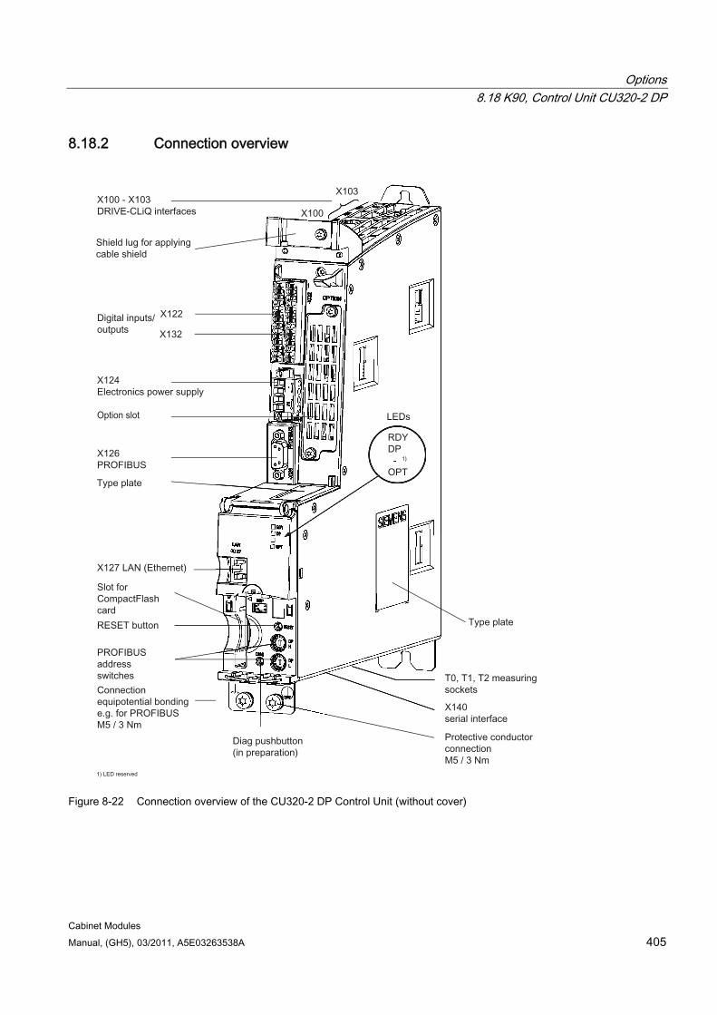
Options 8.18 K90, Control Unit CU320-2 DP
Cabinet Modules Manual, (GH5), 03/2011, A5E03263538A 405
8.18.2 Connection overview
Figure 8-22 Connection overview of the CU320-2 DP Control Unit (without cover)
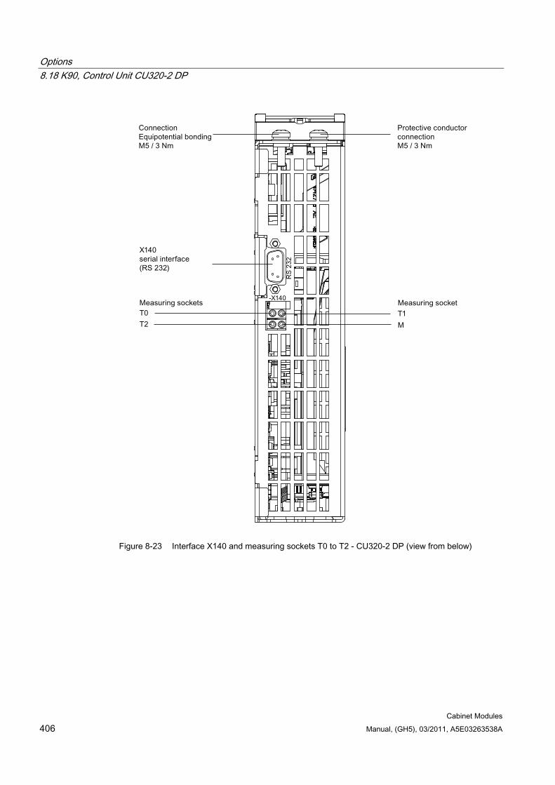
Options 8.18 K90, Control Unit CU320-2 DP
Cabinet Modules 406 Manual, (GH5), 03/2011, A5E03263538A
Figure 8-23 Interface X140 and measuring sockets T0 to T2 - CU320-2 DP (view from below)
Options 8.18 K90, Control Unit CU320-2 DP
Cabinet Modules Manual, (GH5), 03/2011, A5E03263538A 407
CAUTION An equipotential bonding conductor with a cross-section of at least 25 mm² must be used between components in a system that are located a considerable distance from each other.
If a potential bonding conductor is not used, high leakage currents that could destroy the Control Unit or other PROFIBUS nodes can be conducted via the PROFIBUS cable.
CAUTION The CompactFlash card may only be inserted or removed when the Control Unit is in a no-voltage condition.
Non-compliance can result in a loss of data during operation and possibly a plant standstill.
CAUTION The CompactFlash card is an electrostatic sensitive component. ESD regulations must be observed when inserting and removing the card.
CAUTION The option board may only be inserted and removed when the control unit and option board are disconnected from the power supply.
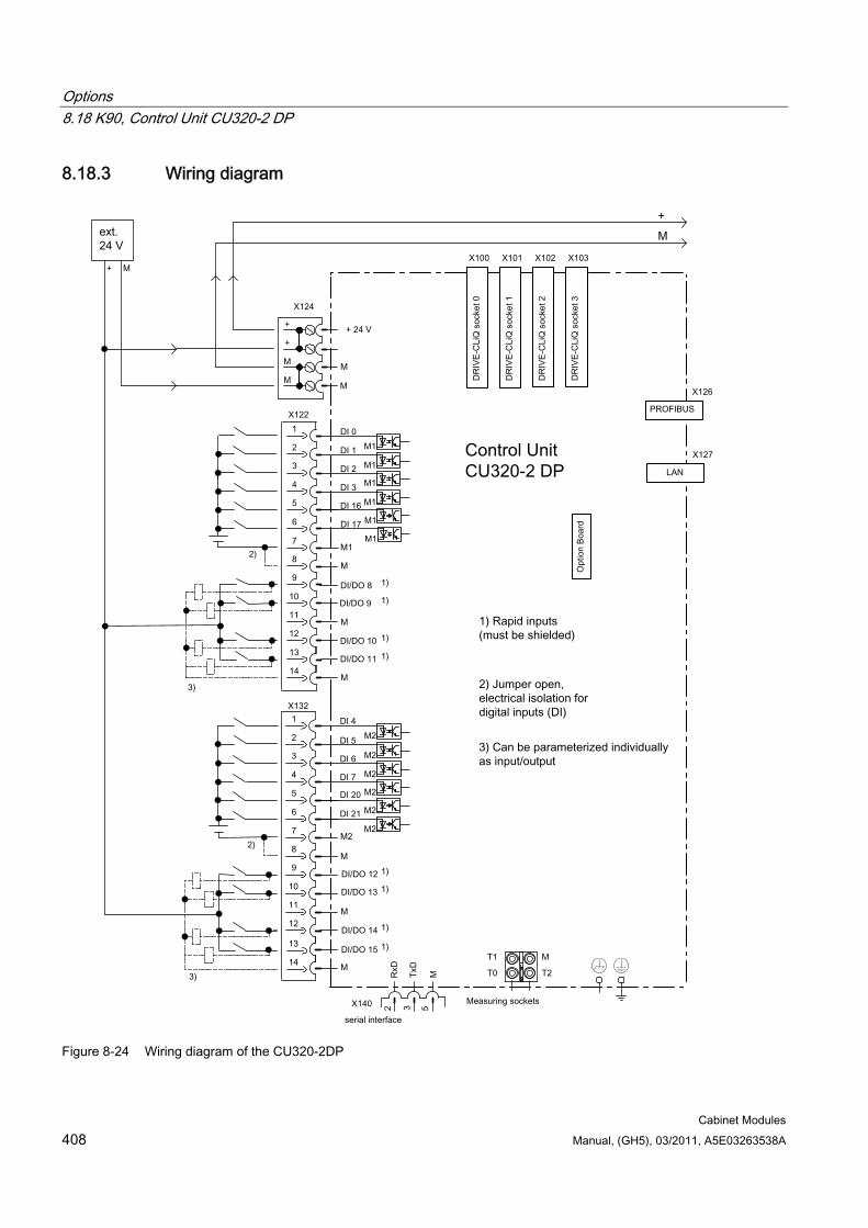
Options 8.18 K90, Control Unit CU320-2 DP
Cabinet Modules 408 Manual, (GH5), 03/2011, A5E03263538A
8.18.3 Wiring diagram
Figure 8-24 Wiring diagram of the CU320-2DP
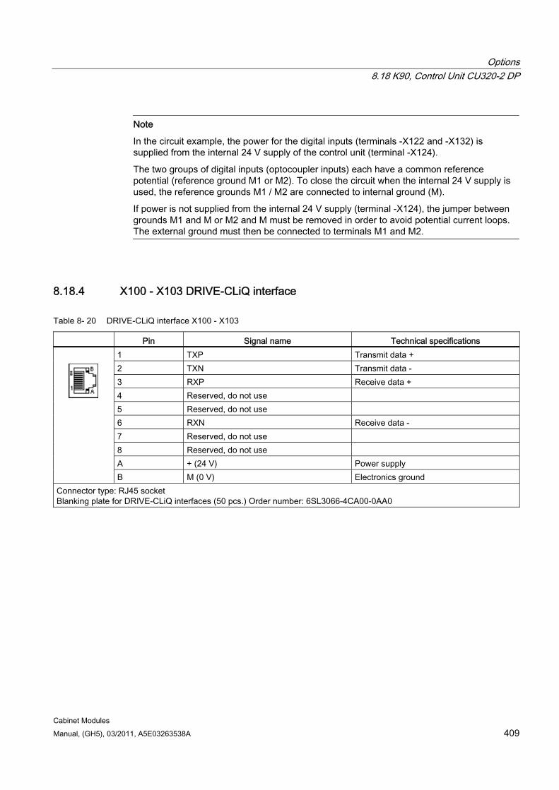
Options 8.18 K90, Control Unit CU320-2 DP
Cabinet Modules Manual, (GH5), 03/2011, A5E03263538A 409
Note
In the circuit example, the power for the digital inputs (terminals -X122 and -X132) is supplied from the internal 24 V supply of the control unit (terminal -X124).
The two groups of digital inputs (optocoupler inputs) each have a common reference potential (reference ground M1 or M2). To close the circuit when the internal 24 V supply is used, the reference grounds M1 / M2 are connected to internal ground (M).
If power is not supplied from the internal 24 V supply (terminal -X124), the jumper between grounds M1 and M or M2 and M must be removed in order to avoid potential current loops. The external ground must then be connected to terminals M1 and M2.
8.18.4 X100 - X103 DRIVE-CLiQ interface
Table 8- 20 DRIVE-CLiQ interface X100 - X103
Pin Signal name Technical specifications 1 TXP Transmit data + 2 TXN Transmit data - 3 RXP Receive data + 4 Reserved, do not use 5 Reserved, do not use 6 RXN Receive data - 7 Reserved, do not use 8 Reserved, do not use A + (24 V) Power supply
B M (0 V) Electronics ground Connector type: RJ45 socket Blanking plate for DRIVE-CLiQ interfaces (50 pcs.) Order number: 6SL3066-4CA00-0AA0
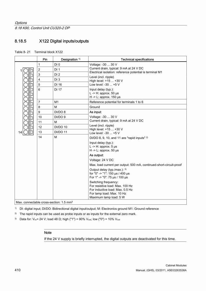
Options 8.18 K90, Control Unit CU320-2 DP
Cabinet Modules 410 Manual, (GH5), 03/2011, A5E03263538A
8.18.5 X122 Digital inputs/outputs
Table 8- 21 Terminal block X122
Pin Designation 1) Technical specifications 1 DI 0 2 DI 1 3 DI 2 4 DI 3 5 DI 16 6 DI 17
Voltage: -30 ... 30 V Current drain, typical: 9 mA at 24 V DC Electrical isolation: reference potential is terminal M1 Level (incl. ripple) High level: +15 ... +30 V Low level: -30 ... +5 V Input delay (typ.): L -> H: approx. 50 μs H -> L: approx. 150 μs
7 M1 Reference potential for terminals 1 to 6 8 M Ground 9 DI/DO 8 10 DI/DO 9 11 M 12 DI/DO 10 13 DI/DO 11
14 M
As input: Voltage: -30 ... 30 V Current drain, typical: 9 mA at 24 V DC Level (incl. ripple) High level: +15 ... +30 V Low level: -30 ... +5 V DI/DO 8, 9, 10, and 11 are "rapid inputs" 2) Input delay (typ.): L -> H: approx. 5 μs H -> L: approx. 50 μs As output: Voltage: 24 V DC Max. load current per output: 500 mA, continued-short-circuit-proof Output delay (typ./max.): 3) for "0" -> "1": 150 μs / 400 μs For 1" -> "0": 75 µs / 100 µs Switching frequency: For resistive load: Max. 100 Hz For inductive load: Max. 0.5 Hz For lamp load: Max. 10 Hz Maximum lamp load: 5 W
Max. connectable cross-section: 1.5 mm²
1) DI: digital input; DI/DO: Bidirectional digital input/output; M: Electronics ground M1: Ground reference 2) The rapid inputs can be used as probe inputs or as inputs for the external zero mark. 3) Data for: Vcc= 24 V; load 48 Ω; high ("1") = 90% Vout; low ("0") = 10% Vout
Note
If the 24 V supply is briefly interrupted, the digital outputs are deactivated for this time.
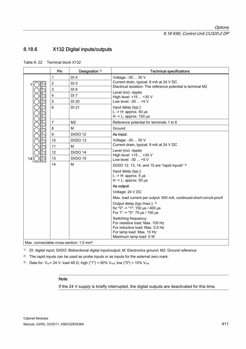
Options 8.18 K90, Control Unit CU320-2 DP
Cabinet Modules Manual, (GH5), 03/2011, A5E03263538A 411
8.18.6 X132 Digital inputs/outputs
Table 8- 22 Terminal block X132
Pin Designation 1) Technical specifications 1 DI 4 2 DI 5 3 DI 6 4 DI 7 5 DI 20 6 DI 21
Voltage: -30 ... 30 V Current drain, typical: 9 mA at 24 V DC Electrical isolation: The reference potential is terminal M2 Level (incl. ripple) High level: +15 ... +30 V Low level: -30 ... +5 V Input delay (typ.): L -> H: approx. 50 μs H -> L: approx. 150 μs
7 M2 Reference potential for terminals 1 to 6 8 M Ground 9 DI/DO 12 10 DI/DO 13 11 M 12 DI/DO 14 13 DI/DO 15
14 M
As input: Voltage: -30 ... 30 V Current drain, typical: 9 mA at 24 V DC Level (incl. ripple) High level: +15 ... +30 V Low level: -30 ... +5 V DI/DO 12, 13, 14, and 15 are "rapid inputs" 2) Input delay (typ.): L -> H: approx. 5 μs H -> L: approx. 50 μs As output: Voltage: 24 V DC Max. load current per output: 500 mA, continued-short-circuit-proof Output delay (typ./max.): 3) for "0" -> "1": 150 μs / 400 μs For 1" -> "0": 75 µs / 100 µs Switching frequency: For resistive load: Max. 100 Hz For inductive load: Max. 0.5 Hz For lamp load: Max. 10 Hz Maximum lamp load: 5 W
Max. connectable cross-section: 1.5 mm²
1) DI: digital input; DI/DO: Bidirectional digital input/output; M: Electronics ground; M2: Ground reference 2) The rapid inputs can be used as probe inputs or as inputs for the external zero mark. 3) Data for: Vcc= 24 V; load 48 Ω; high ("1") = 90% Vout; low ("0") = 10% Vout
Note
If the 24 V supply is briefly interrupted, the digital outputs are deactivated for this time.
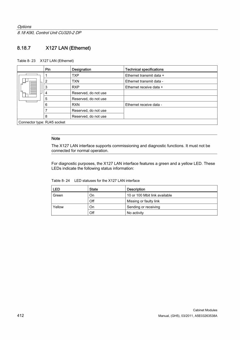
Options 8.18 K90, Control Unit CU320-2 DP
Cabinet Modules 412 Manual, (GH5), 03/2011, A5E03263538A
8.18.7 X127 LAN (Ethernet)
Table 8- 23 X127 LAN (Ethernet)
Pin Designation Technical specifications 1 TXP Ethernet transmit data + 2 TXN Ethernet transmit data - 3 RXP Ethernet receive data + 4 Reserved, do not use 5 Reserved, do not use 6 RXN Ethernet receive data - 7 Reserved, do not use
8 Reserved, do not use
Connector type: RJ45 socket
Note
The X127 LAN interface supports commissioning and diagnostic functions. It must not be connected for normal operation.
For diagnostic purposes, the X127 LAN interface features a green and a yellow LED. These LEDs indicate the following status information:
Table 8- 24 LED statuses for the X127 LAN interface
LED State Description On 10 or 100 Mbit link available Green Off Missing or faulty link On Sending or receiving Yellow Off No activity
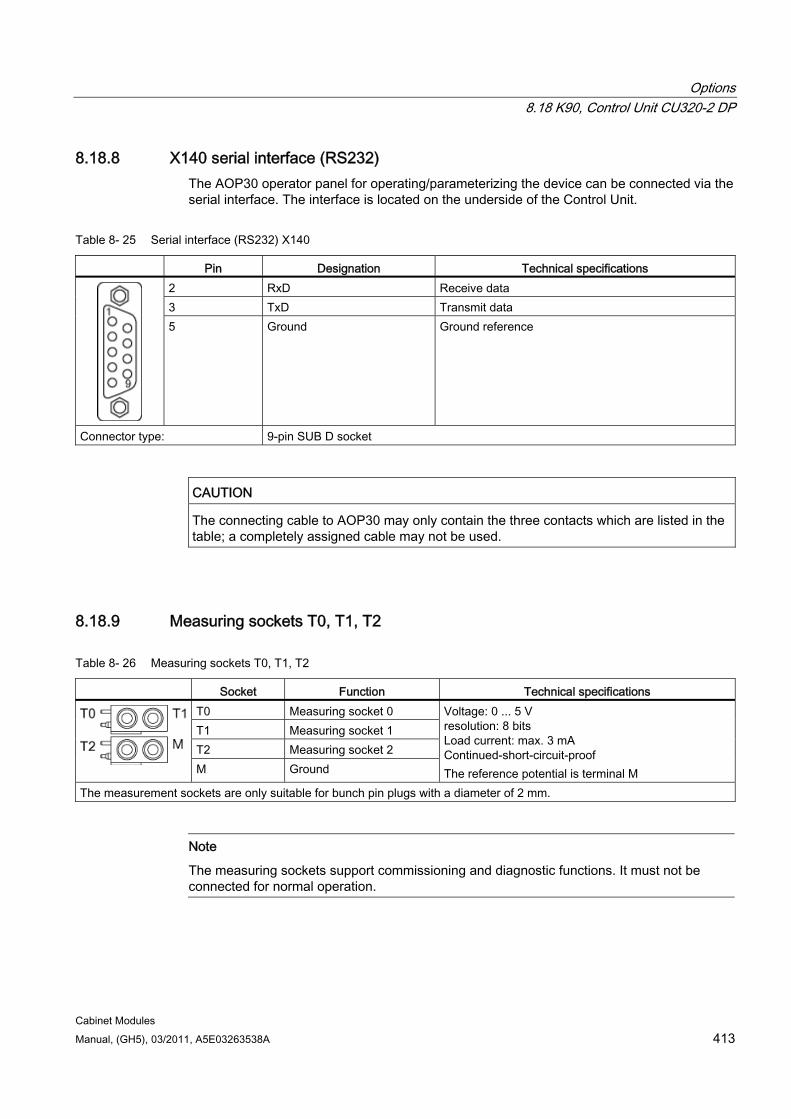
Options 8.18 K90, Control Unit CU320-2 DP
Cabinet Modules Manual, (GH5), 03/2011, A5E03263538A 413
8.18.8 X140 serial interface (RS232) The AOP30 operator panel for operating/parameterizing the device can be connected via the serial interface. The interface is located on the underside of the Control Unit.
Table 8- 25 Serial interface (RS232) X140
Pin Designation Technical specifications 2 RxD Receive data 3 TxD Transmit data
5 Ground Ground reference
Connector type: 9-pin SUB D socket
CAUTION The connecting cable to AOP30 may only contain the three contacts which are listed in the table; a completely assigned cable may not be used.
8.18.9 Measuring sockets T0, T1, T2
Table 8- 26 Measuring sockets T0, T1, T2
Socket Function Technical specifications T0 Measuring socket 0 T1 Measuring socket 1 T2 Measuring socket 2
M Ground
Voltage: 0 ... 5 V resolution: 8 bits Load current: max. 3 mA Continued-short-circuit-proof The reference potential is terminal M
The measurement sockets are only suitable for bunch pin plugs with a diameter of 2 mm.
Note
The measuring sockets support commissioning and diagnostic functions. It must not be connected for normal operation.
Options 8.18 K90, Control Unit CU320-2 DP
Cabinet Modules 414 Manual, (GH5), 03/2011, A5E03263538A
8.18.10 CompactFlash card
Description The computing capacity required and utilization of the CU320-2 Control Unit can be calculated with the SIZER engineering tool. The firmware options are supplied in license form, which are written to the CompactFlash card in the factory as license codes. The firmware options can also be enabled on-site, for example, if the required expanded performance is not known at the time of placing the order. You will need the serial number of the CompactFlash card and the order number of the firmware option to be enabled. With this information, you can purchase the associated license code from a license database and enable the firmware option.
The license code is only valid for the CompactFlash card declared and cannot be transferred to other CompactFlash cards.
CAUTION Handle the CompactFlash card with care.
The data stored on the CompactFlash card must not be changed manually. Only the STARTER program can modify the data.
If you do not do this, all the data on the CompactFlash card will be lost (parameters, software license, etc.).
The CompactFlash card may only be inserted or removed after the Control Unit CU320-2 has been switched off.
8.18.10.1 Using the memory card
Description The STARTER commissioning tool is used to store configuration data centrally on the CompactFlash card. This ensures that if the Control Unit is defective, it can be simply replaced without the loss of any data. It also enables data to be stored on external storage media.
The data on the CompactFlash card can also be accessed using a CompactFlash card reader connected to a PC. This card reader is not included in the scope of supply.
Options 8.18 K90, Control Unit CU320-2 DP
Cabinet Modules Manual, (GH5), 03/2011, A5E03263538A 415
System prerequisites for installing STARTER The following minimum hardware requirements must be complied with:
PG or PC Pentium III min. 800 MHz (recommended > 1 GHz)
512 MB main memory (1 GB recommended)
Screen resolution 1024 × 768 pixels, 16-bit color depth
Free hard disk memory: min. 2 GB;
The following minimum software requirements apply when using STARTER without STEP 7 having been installed:
Microsoft Windows 2000 SP4
Microsoft Windows 2003 Server SP1, SP2
Microsoft Windows XP Professional SP2, SP3
Microsoft Windows VISTA Business SP1 *)
Microsoft Windows VISTA Ultimate SP1 *)
Microsoft Internet Explorer V6.0 or higher
*) DCC cannot be used.
STARTER can be used on these operating systems only if it does not include the DCC option.
Note
If STARTER is used in combination with other STEP7 components, the prerequisites for the S7 components shall apply.
Additional system requirements for installing a CompactFlash card reader Free USB connection
CD-ROM drive (for installing the driver for the card reader)
Options 8.18 K90, Control Unit CU320-2 DP
Cabinet Modules 416 Manual, (GH5), 03/2011, A5E03263538A
8.18.10.2 Data functions Once a card reader has been connected and successfully installed, the data on the CompactFlash card can be accessed in the same way as data stored on other PC storage media (e.g. access to hard disk, memory stick, etc.). To access its data, the CompactFlash card must first be removed from the Control Unit CU320-2 and inserted in the card reader connected to the PC.
The actual procedure for accessing the CompactFlash card data depends on the operating system used.
CAUTION The data stored on the CompactFlash card must not be changed manually. Only the STARTER program can modify the data.
If you do not do this, all the data on the CompactFlash card will be lost (parameters, software license, etc.).
8.18.10.3 Saving the memory card parameter settings Following commissioning, it is advisable to back up the data on the CompactFlash card to an external storage medium (hard disk, data carrier, etc.).
To do this, the CompactFlash card is read via a card reader connected to a PC. Ensure that all the files and directories are stored in the same form as on the CompactFlash card.
If necessary, the device status following commissioning of the drive can be restored by uploading the saved data to the CompactFlash card.
CAUTION The CompactFlash card may only be inserted or removed after the Control Unit CU320-2 has been switched off.
If you do not do this, all the data on the CompactFlash card will be lost (parameters, software license, etc.).
If you remove the CompactFlash Card in operation, alarm A01100 "CU: CompactFlash card removed" is output.
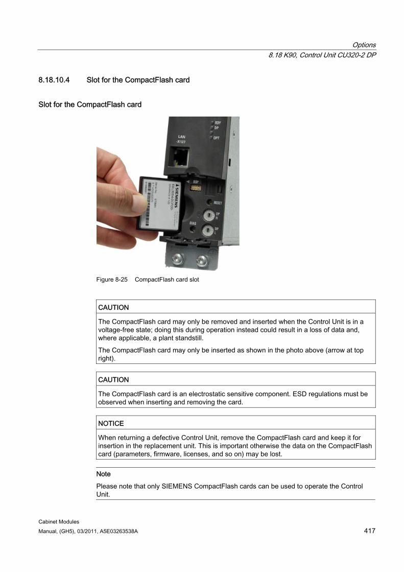
Options 8.18 K90, Control Unit CU320-2 DP
Cabinet Modules Manual, (GH5), 03/2011, A5E03263538A 417
8.18.10.4 Slot for the CompactFlash card
Slot for the CompactFlash card
Figure 8-25 CompactFlash card slot
CAUTION The CompactFlash card may only be removed and inserted when the Control Unit is in a voltage-free state; doing this during operation instead could result in a loss of data and, where applicable, a plant standstill.
The CompactFlash card may only be inserted as shown in the photo above (arrow at top right).
CAUTION The CompactFlash card is an electrostatic sensitive component. ESD regulations must be observed when inserting and removing the card.
NOTICE When returning a defective Control Unit, remove the CompactFlash card and keep it for insertion in the replacement unit. This is important otherwise the data on the CompactFlash card (parameters, firmware, licenses, and so on) may be lost.
Note
Please note that only SIEMENS CompactFlash cards can be used to operate the Control Unit.
Options 8.19 K94, Performance extension for CU320-2
Cabinet Modules 418 Manual, (GH5), 03/2011, A5E03263538A
8.19 K94, Performance extension for CU320-2
Availability of option This option is available for the following options:
Option K90, Control Unit CU320-2 PROFIBUS
Option K95, Control Unit CU320-2 PROFINET
Description A CU320-2 Control Unit can perform the communication, open-loop and closed-loop control functions for several power units. The computing capacity requirement increases in proportion to the number of power units and system components and in relation to the dynamic response required. The full computing capacity of the CU320-2 Control Unit is available only with performance enhancement.
In addition to the firmware, the CompactFlash Card also contains licensing codes, which are required to enable firmware options (such as performance enhancement and the Safety Integrated Extended functions).
Options 8.20 K95, Control Unit CU320-2 PN
Cabinet Modules Manual, (GH5), 03/2011, A5E03263538A 419
8.20 K95, Control Unit CU320-2 PN
8.20.1 General information
Availability of option This option is available for the following S120 cabinet modules:
Basic Line Modules
Smart Line Modules
Active Line Modules
Booksize Cabinet Kits
Chassis format Motor Modules
Note
For Double Motor Modules in the booksize format, only one common Control Unit is available for both Motor Modules.
Description With option K95, a CU320-2 PN Control Unit is installed in the Line Modules and Motor Modules of the drive line-up; this assumes the functions of communication, open-loop control, and closed-loop control for up to 4 Motor Modules, in addition to 1 Line Module.
The connection to the relevant modules and any additional I/O modules is established via DRIVE-CLiQ. A standard PROFINET interface is available for higher-level communication.
The unit can communicate with other participants via PROFINET or the DRIVE-CLiQ interface, see SINAMICS Low-Voltage Engineering Manual on the customer DVD supplied with the device.
Note CU320-2 Control Unit without performance enhancement
Without performance enhancement, it is generally possible to operate 2 Motor Modules plus 1 Line Module.
Note Performance enhancement
The computing capacity required increases in proportion to the number of connected Motor Modules and system components and in relation to the dynamic response required. The full computing capacity of the CU320-2 Control Unit is available only with performance enhancement.
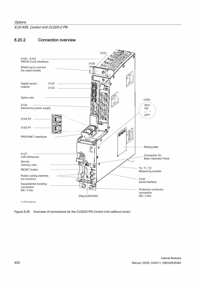
Options 8.20 K95, Control Unit CU320-2 PN
Cabinet Modules 420 Manual, (GH5), 03/2011, A5E03263538A
8.20.2 Connection overview
Figure 8-26 Overview of connections for the CU3202 PN Control Unit (without cover)
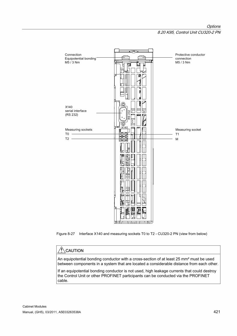
Options 8.20 K95, Control Unit CU320-2 PN
Cabinet Modules Manual, (GH5), 03/2011, A5E03263538A 421
Figure 8-27 Interface X140 and measuring sockets T0 to T2 - CU320-2 PN (view from below)
CAUTION An equipotential bonding conductor with a cross-section of at least 25 mm² must be used between components in a system that are located a considerable distance from each other.
If an equipotential bonding conductor is not used, high leakage currents that could destroy the Control Unit or other PROFINET participants can be conducted via the PROFINET cable.
Options 8.20 K95, Control Unit CU320-2 PN
Cabinet Modules 422 Manual, (GH5), 03/2011, A5E03263538A
CAUTION The CompactFlash card may only be inserted or removed when the Control Unit is in a no-voltage condition.
Non-compliance can result in a loss of data during operation and possibly a plant standstill.
CAUTION The CompactFlash card is an electrostatic sensitive component. ESD regulations must be observed when inserting and removing the card.
CAUTION The Option Board may only be inserted and removed when the Control Unit and Option Board are disconnected from the power supply.
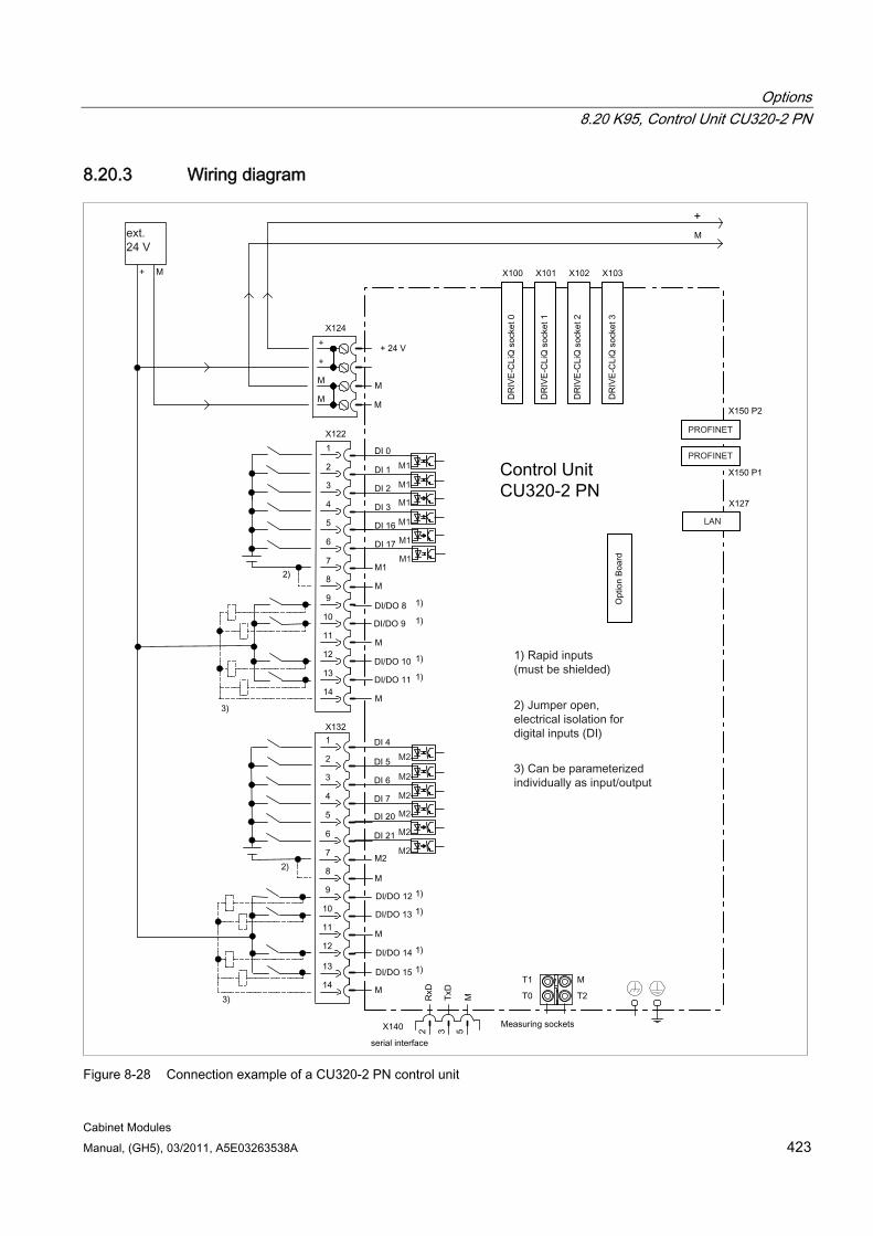
Options 8.20 K95, Control Unit CU320-2 PN
Cabinet Modules Manual, (GH5), 03/2011, A5E03263538A 423
8.20.3 Wiring diagram
Figure 8-28 Connection example of a CU320-2 PN control unit
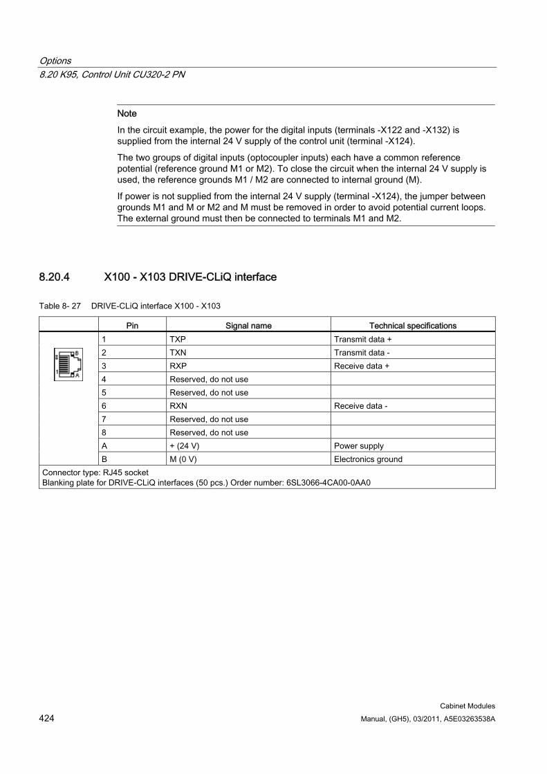
Options 8.20 K95, Control Unit CU320-2 PN
Cabinet Modules 424 Manual, (GH5), 03/2011, A5E03263538A
Note
In the circuit example, the power for the digital inputs (terminals -X122 and -X132) is supplied from the internal 24 V supply of the control unit (terminal -X124).
The two groups of digital inputs (optocoupler inputs) each have a common reference potential (reference ground M1 or M2). To close the circuit when the internal 24 V supply is used, the reference grounds M1 / M2 are connected to internal ground (M).
If power is not supplied from the internal 24 V supply (terminal -X124), the jumper between grounds M1 and M or M2 and M must be removed in order to avoid potential current loops. The external ground must then be connected to terminals M1 and M2.
8.20.4 X100 - X103 DRIVE-CLiQ interface
Table 8- 27 DRIVE-CLiQ interface X100 - X103
Pin Signal name Technical specifications 1 TXP Transmit data + 2 TXN Transmit data - 3 RXP Receive data + 4 Reserved, do not use 5 Reserved, do not use 6 RXN Receive data - 7 Reserved, do not use 8 Reserved, do not use A + (24 V) Power supply
B M (0 V) Electronics ground Connector type: RJ45 socket Blanking plate for DRIVE-CLiQ interfaces (50 pcs.) Order number: 6SL3066-4CA00-0AA0

Options 8.20 K95, Control Unit CU320-2 PN
Cabinet Modules Manual, (GH5), 03/2011, A5E03263538A 425
8.20.5 X122 Digital inputs/outputs
Table 8- 28 Terminal block X122
Pin Designation 1) Technical specifications 1 DI 0 2 DI 1 3 DI 2 4 DI 3 5 DI 16 6 DI 17
Voltage: -30 ... 30 V Current drain, typical: 9 mA at 24 V DC Electrical isolation: reference potential is terminal M1 Level (incl. ripple) High level: +15 ... +30 V Low level: -30 ... +5 V Input delay (typ.): L -> H: approx. 50 μs H -> L: approx. 150 μs
7 M1 Reference potential for terminals 1 to 6 8 M Ground 9 DI/DO 8 10 DI/DO 9 11 M 12 DI/DO 10 13 DI/DO 11
14 M
As input: Voltage: -30 ... 30 V Current drain, typical: 9 mA at 24 V DC Level (incl. ripple) High level: +15 ... +30 V Low level: -30 ... +5 V DI/DO 8, 9, 10, and 11 are "rapid inputs" 2) Input delay (typ.): L -> H: approx. 5 μs H -> L: approx. 50 μs As output: Voltage: 24 V DC Max. load current per output: 500 mA, continued-short-circuit-proof Output delay (typ./max.): 3) for "0" -> "1": 150 μs / 400 μs For 1" -> "0": 75 µs / 100 µs Switching frequency: For resistive load: Max. 100 Hz For inductive load: Max. 0.5 Hz For lamp load: Max. 10 Hz Maximum lamp load: 5 W
Max. connectable cross-section: 1.5 mm²
1) DI: digital input; DI/DO: Bidirectional digital input/output; M: Electronics ground M1: Ground reference 2) The rapid inputs can be used as probe inputs or as inputs for the external zero mark. 3) Data for: Vcc= 24 V; load 48 Ω; high ("1") = 90% Vout; low ("0") = 10% Vout
Note
If the 24 V supply is briefly interrupted, the digital outputs are deactivated for this time.
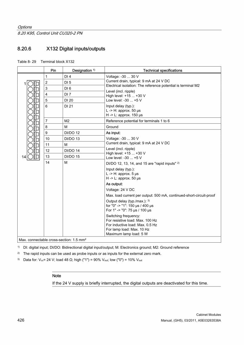
Options 8.20 K95, Control Unit CU320-2 PN
Cabinet Modules 426 Manual, (GH5), 03/2011, A5E03263538A
8.20.6 X132 Digital inputs/outputs
Table 8- 29 Terminal block X132
Pin Designation 1) Technical specifications 1 DI 4 2 DI 5 3 DI 6 4 DI 7 5 DI 20 6 DI 21
Voltage: -30 ... 30 V Current drain, typical: 9 mA at 24 V DC Electrical isolation: The reference potential is terminal M2 Level (incl. ripple) High level: +15 ... +30 V Low level: -30 ... +5 V Input delay (typ.): L -> H: approx. 50 μs H -> L: approx. 150 μs
7 M2 Reference potential for terminals 1 to 6 8 M Ground 9 DI/DO 12 10 DI/DO 13 11 M 12 DI/DO 14 13 DI/DO 15
14 M
As input: Voltage: -30 ... 30 V Current drain, typical: 9 mA at 24 V DC Level (incl. ripple) High level: +15 ... +30 V Low level: -30 ... +5 V DI/DO 12, 13, 14, and 15 are "rapid inputs" 2) Input delay (typ.): L -> H: approx. 5 μs H -> L: approx. 50 μs As output: Voltage: 24 V DC Max. load current per output: 500 mA, continued-short-circuit-proof Output delay (typ./max.): 3) for "0" -> "1": 150 μs / 400 μs For 1" -> "0": 75 µs / 100 µs Switching frequency: For resistive load: Max. 100 Hz For inductive load: Max. 0.5 Hz For lamp load: Max. 10 Hz Maximum lamp load: 5 W
Max. connectable cross-section: 1.5 mm²
1) DI: digital input; DI/DO: Bidirectional digital input/output; M: Electronics ground; M2: Ground reference 2) The rapid inputs can be used as probe inputs or as inputs for the external zero mark. 3) Data for: Vcc= 24 V; load 48 Ω; high ("1") = 90% Vout; low ("0") = 10% Vout
Note
If the 24 V supply is briefly interrupted, the digital outputs are deactivated for this time.
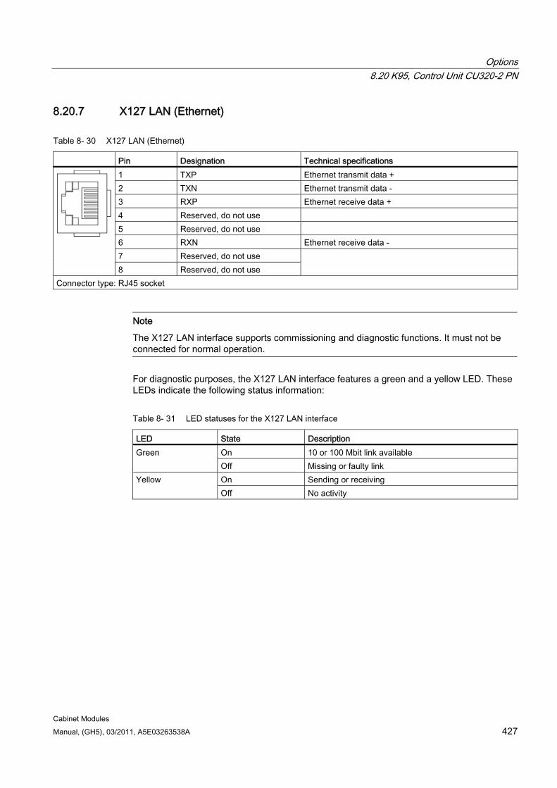
Options 8.20 K95, Control Unit CU320-2 PN
Cabinet Modules Manual, (GH5), 03/2011, A5E03263538A 427
8.20.7 X127 LAN (Ethernet)
Table 8- 30 X127 LAN (Ethernet)
Pin Designation Technical specifications 1 TXP Ethernet transmit data + 2 TXN Ethernet transmit data - 3 RXP Ethernet receive data + 4 Reserved, do not use 5 Reserved, do not use 6 RXN Ethernet receive data - 7 Reserved, do not use
8 Reserved, do not use
Connector type: RJ45 socket
Note
The X127 LAN interface supports commissioning and diagnostic functions. It must not be connected for normal operation.
For diagnostic purposes, the X127 LAN interface features a green and a yellow LED. These LEDs indicate the following status information:
Table 8- 31 LED statuses for the X127 LAN interface
LED State Description On 10 or 100 Mbit link available Green Off Missing or faulty link On Sending or receiving Yellow Off No activity

Options 8.20 K95, Control Unit CU320-2 PN
Cabinet Modules 428 Manual, (GH5), 03/2011, A5E03263538A
8.20.8 X140 serial interface (RS232) The AOP30 operator panel for operating/parameterizing the device can be connected via the serial interface. The interface is located on the underside of the Control Unit.
Table 8- 32 Serial interface (RS232) X140
Pin Designation Technical specifications 2 RxD Receive data 3 TxD Transmit data
5 Ground Ground reference
Connector type: 9-pin SUB D socket
CAUTION The connecting cable to AOP30 may only contain the three contacts which are listed in the table; a completely assigned cable may not be used.
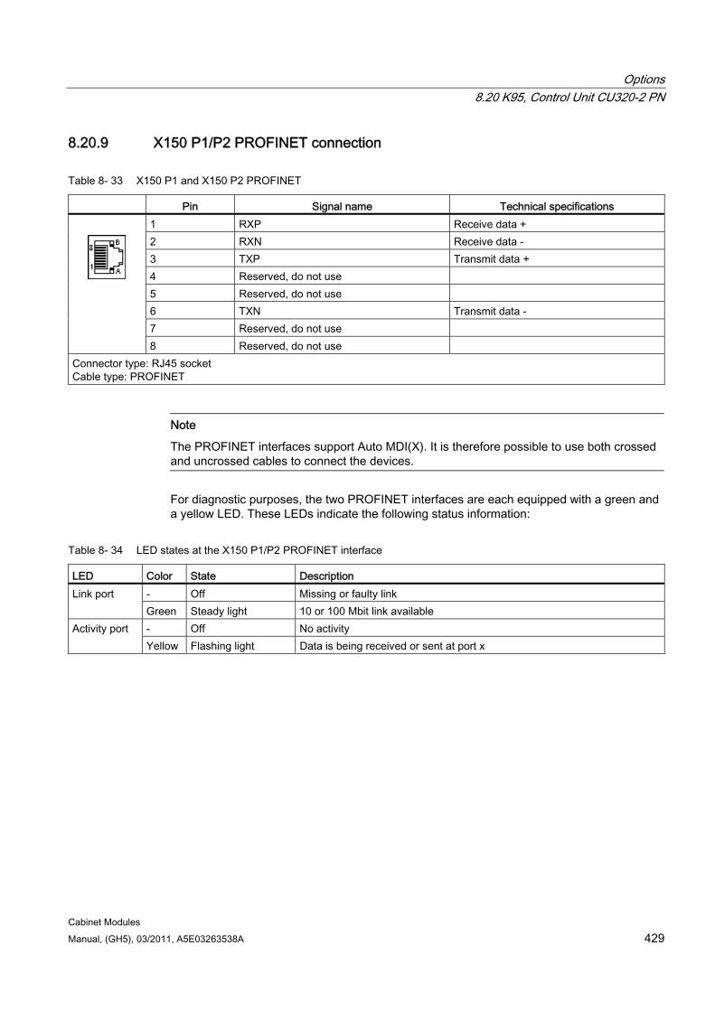
Options 8.20 K95, Control Unit CU320-2 PN
Cabinet Modules Manual, (GH5), 03/2011, A5E03263538A 429
8.20.9 X150 P1/P2 PROFINET connection
Table 8- 33 X150 P1 and X150 P2 PROFINET
Pin Signal name Technical specifications 1 RXP Receive data + 2 RXN Receive data - 3 TXP Transmit data + 4 Reserved, do not use 5 Reserved, do not use 6 TXN Transmit data - 7 Reserved, do not use
8 Reserved, do not use Connector type: RJ45 socket Cable type: PROFINET
Note
The PROFINET interfaces support Auto MDI(X). It is therefore possible to use both crossed and uncrossed cables to connect the devices.
For diagnostic purposes, the two PROFINET interfaces are each equipped with a green and a yellow LED. These LEDs indicate the following status information:
Table 8- 34 LED states at the X150 P1/P2 PROFINET interface
LED Color State Description - Off Missing or faulty link Link port Green Steady light 10 or 100 Mbit link available - Off No activity Activity port Yellow Flashing light Data is being received or sent at port x
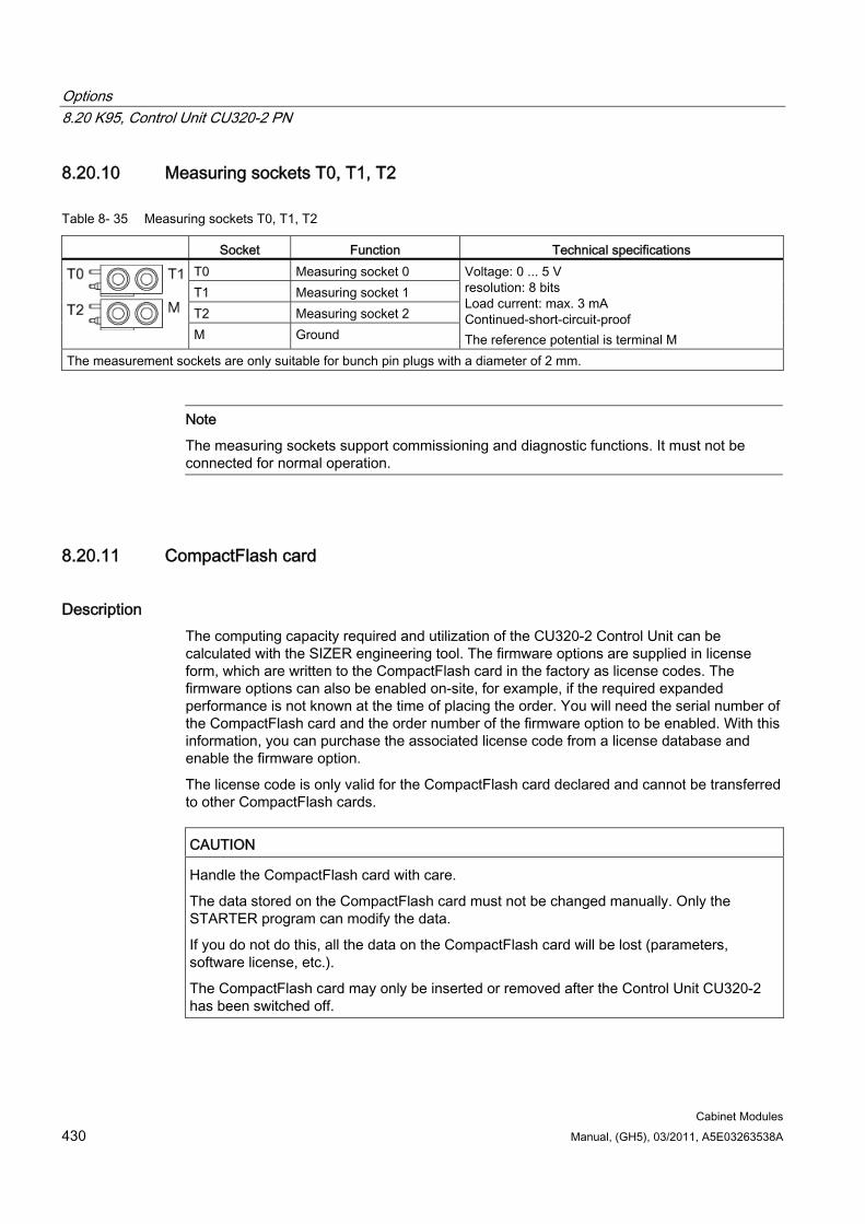
Options 8.20 K95, Control Unit CU320-2 PN
Cabinet Modules 430 Manual, (GH5), 03/2011, A5E03263538A
8.20.10 Measuring sockets T0, T1, T2
Table 8- 35 Measuring sockets T0, T1, T2
Socket Function Technical specifications T0 Measuring socket 0 T1 Measuring socket 1 T2 Measuring socket 2
M Ground
Voltage: 0 ... 5 V resolution: 8 bits Load current: max. 3 mA Continued-short-circuit-proof The reference potential is terminal M
The measurement sockets are only suitable for bunch pin plugs with a diameter of 2 mm.
Note
The measuring sockets support commissioning and diagnostic functions. It must not be connected for normal operation.
8.20.11 CompactFlash card
Description The computing capacity required and utilization of the CU320-2 Control Unit can be calculated with the SIZER engineering tool. The firmware options are supplied in license form, which are written to the CompactFlash card in the factory as license codes. The firmware options can also be enabled on-site, for example, if the required expanded performance is not known at the time of placing the order. You will need the serial number of the CompactFlash card and the order number of the firmware option to be enabled. With this information, you can purchase the associated license code from a license database and enable the firmware option.
The license code is only valid for the CompactFlash card declared and cannot be transferred to other CompactFlash cards.
CAUTION Handle the CompactFlash card with care.
The data stored on the CompactFlash card must not be changed manually. Only the STARTER program can modify the data.
If you do not do this, all the data on the CompactFlash card will be lost (parameters, software license, etc.).
The CompactFlash card may only be inserted or removed after the Control Unit CU320-2 has been switched off.
Options 8.20 K95, Control Unit CU320-2 PN
Cabinet Modules Manual, (GH5), 03/2011, A5E03263538A 431
8.20.11.1 Using the memory card
Description The STARTER commissioning tool is used to store configuration data centrally on the CompactFlash card. This ensures that if the Control Unit is defective, it can be simply replaced without the loss of any data. It also enables data to be stored on external storage media.
The data on the CompactFlash card can also be accessed using a CompactFlash card reader connected to a PC. This card reader is not included in the scope of supply.
System prerequisites for installing STARTER The following minimum hardware requirements must be complied with:
PG or PC Pentium III min. 800 MHz (recommended > 1 GHz)
512 MB main memory (1 GB recommended)
Screen resolution 1024 × 768 pixels, 16-bit color depth
Free hard disk memory: min. 2 GB;
The following minimum software requirements apply when using STARTER without STEP 7 having been installed:
Microsoft Windows 2000 SP4
Microsoft Windows 2003 Server SP1, SP2
Microsoft Windows XP Professional SP2, SP3
Microsoft Windows VISTA Business SP1 *)
Microsoft Windows VISTA Ultimate SP1 *)
Microsoft Internet Explorer V6.0 or higher
*) DCC cannot be used.
STARTER can be used on these operating systems only if it does not include the DCC option.
Note
If STARTER is used in combination with other STEP7 components, the prerequisites for the S7 components shall apply.
Additional system requirements for installing a CompactFlash card reader Free USB connection
CD-ROM drive (for installing the driver for the card reader)
Options 8.20 K95, Control Unit CU320-2 PN
Cabinet Modules 432 Manual, (GH5), 03/2011, A5E03263538A
8.20.11.2 Data functions Once a card reader has been connected and successfully installed, the data on the CompactFlash card can be accessed in the same way as data stored on other PC storage media (e.g. access to hard disk, memory stick, etc.). To access its data, the CompactFlash card must first be removed from the Control Unit CU320-2 and inserted in the card reader connected to the PC.
The actual procedure for accessing the CompactFlash card data depends on the operating system used.
CAUTION The data stored on the CompactFlash card must not be changed manually. Only the STARTER program can modify the data.
If you do not do this, all the data on the CompactFlash card will be lost (parameters, software license, etc.).
8.20.11.3 Saving the memory card parameter settings Following commissioning, it is advisable to back up the data on the CompactFlash card to an external storage medium (hard disk, data carrier, etc.).
To do this, the CompactFlash card is read via a card reader connected to a PC. Ensure that all the files and directories are stored in the same form as on the CompactFlash card.
If necessary, the device status following commissioning of the drive can be restored by uploading the saved data to the CompactFlash card.
CAUTION The CompactFlash card may only be inserted or removed after the Control Unit CU320-2 has been switched off.
If you do not do this, all the data on the CompactFlash card will be lost (parameters, software license, etc.).
If you remove the CompactFlash Card in operation, alarm A01100 "CU: CompactFlash card removed" is output.

Options 8.20 K95, Control Unit CU320-2 PN
Cabinet Modules Manual, (GH5), 03/2011, A5E03263538A 433
8.20.11.4 Slot for the CompactFlash card
Slot for the CompactFlash card
Figure 8-29 CompactFlash card slot
CAUTION The CompactFlash card may only be removed and inserted when the Control Unit is in a voltage-free state; doing this during operation instead could result in a loss of data and, where applicable, a plant standstill.
The CompactFlash card may only be inserted as shown in the photo above (arrow at top right).
CAUTION The CompactFlash card is an electrostatic sensitive component. ESD regulations must be observed when inserting and removing the card.
NOTICE When returning a defective Control Unit, remove the CompactFlash card and keep it for insertion in the replacement unit. This is important otherwise the data on the CompactFlash card (parameters, firmware, licenses, and so on) may be lost.
Note
Please note that only SIEMENS CompactFlash cards can be used to operate the Control Unit.
Options 8.21 L00, use in the first environment according to EN 61800-3, Category C2 (TN/TT systems)
Cabinet Modules 434 Manual, (GH5), 03/2011, A5E03263538A
8.21 L00, use in the first environment according to EN 61800-3, Category C2 (TN/TT systems)
Availability of option This option is available for the following S120 Cabinet Modules:
Basic Line Modules
Smart Line Modules
Active Line Modules
Description To limit the emitted interference, the drive converters are equipped as standard with a radio interference suppression filter that conforms to the limits defined in Category C3. By using the optional line filter (option L00) and additional measures performed in the factory - which are required in the cabinets - then SINAMICS S120 Cabinet Modules also comply with the limit values for use in the first environment (category C2) according to EN 61800-3.
The line filters are designed for connection to grounded line supplies (TN or TT line supplies).
Restrictions
Note
Option L00, use in the first environment (category C2) according to EN 61800-3, is not available for Line Modules in a parallel connection.
Note
The measures required on the customer's side, which must be performed to fulfill the limit values for use in the first environment (category C2) according to EN61800-3, are listed in the "Configuration Manual SINAMICS Low Voltage" on the customer DVD supplied with the device.
Note
The optional line filter must always be combined with a line reactor, otherwise it cannot achieve its full filter effect.
Note
To allow the power cable shield to be connected in conformance with EMC requirements, an additional EMC shield bus (M70 option) is factory fitted at the converter input and output.
Note
It is not possible to use the insulation monitoring function (option L87) in conjunction with the optional line filter.
Options 8.22 L07, dv/dt filter compact plus Voltage Peak Limiter
Cabinet Modules Manual, (GH5), 03/2011, A5E03263538A 435
8.22 L07, dv/dt filter compact plus Voltage Peak Limiter
Availability of option This option is available for the following S120 Cabinet Modules:
Chassis format Motor Modules
Description The dv/dt filter compact plus Voltage Peak Limiter comprises two components: the dv/dt reactor and the voltage-limiting network (Voltage Peak Limiter), which cuts off the voltage peaks and feeds back the energy into the DC link. The dv/dt filter compact plus Voltage Peak Limiter is designed for use with motors for which the voltage strength of the insulation system is unknown or insufficient.
The dv/dt filter compact plus Voltage Peak Limiter limits the voltage load on the motor cables to values in accordance with the limit value curve A in compliance with IEC/TS 60034-25.
The rate of voltage rise is limited to < 1600 V/µs, the peak voltages are limited to < 1400 V.
Note
Operation of standard motors with standard insulation and without insulated bearing is possible on SINAMICS converters up to line supply voltages of 690 V.
Restrictions The following constraints should be noted when a dv/dt filter compact plus Voltage Peak Limiter is used:
The output frequency is limited to no more than 150 Hz.
Maximum permissible motor cable lengths:
– Shielded cables: max. 100 m (e.g. Protodur NYCWY)
– Unshielded cables: max. 150 m (e.g. Protodur NYY)
WARNING When a dv/dt filter compact plus Voltage Peak Limiter is used, the drive must not be operated in uninterrupted duty with an output frequency lower than 10 Hz.
A maximum load duration of 5 minutes at an output frequency lower than 10 Hz is permissible, provided that the drive is operated with an output frequency higher than 10 Hz for a period of 5 minutes thereafter.
Uninterrupted duty at an output frequency less than 10 Hz can produce thermal overload and destroy the dv/dt filter.
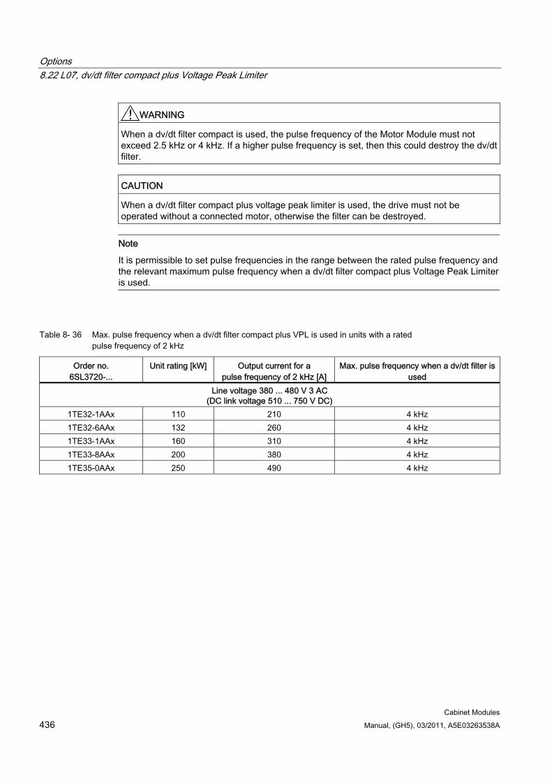
Options 8.22 L07, dv/dt filter compact plus Voltage Peak Limiter
Cabinet Modules 436 Manual, (GH5), 03/2011, A5E03263538A
WARNING When a dv/dt filter compact is used, the pulse frequency of the Motor Module must not exceed 2.5 kHz or 4 kHz. If a higher pulse frequency is set, then this could destroy the dv/dt filter.
CAUTION When a dv/dt filter compact plus voltage peak limiter is used, the drive must not be operated without a connected motor, otherwise the filter can be destroyed.
Note
It is permissible to set pulse frequencies in the range between the rated pulse frequency and the relevant maximum pulse frequency when a dv/dt filter compact plus Voltage Peak Limiter is used.
Table 8- 36 Max. pulse frequency when a dv/dt filter compact plus VPL is used in units with a rated pulse frequency of 2 kHz
Order no. 6SL3720-...
Unit rating [kW] Output current for a pulse frequency of 2 kHz [A]
Max. pulse frequency when a dv/dt filter is used
Line voltage 380 ... 480 V 3 AC (DC link voltage 510 ... 750 V DC)
1TE32-1AAx 110 210 4 kHz 1TE32-6AAx 132 260 4 kHz 1TE33-1AAx 160 310 4 kHz 1TE33-8AAx 200 380 4 kHz 1TE35-0AAx 250 490 4 kHz
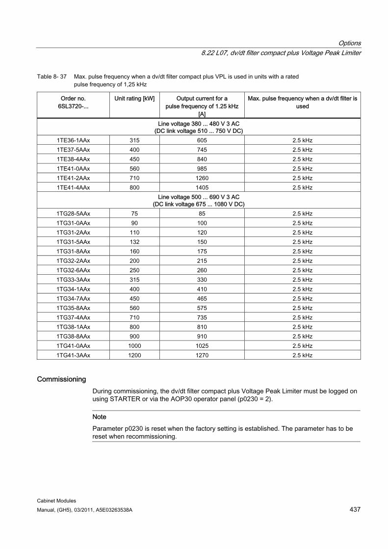
Options 8.22 L07, dv/dt filter compact plus Voltage Peak Limiter
Cabinet Modules Manual, (GH5), 03/2011, A5E03263538A 437
Table 8- 37 Max. pulse frequency when a dv/dt filter compact plus VPL is used in units with a rated pulse frequency of 1,25 kHz
Order no. 6SL3720-...
Unit rating [kW] Output current for a pulse frequency of 1.25 kHz
[A]
Max. pulse frequency when a dv/dt filter is used
Line voltage 380 ... 480 V 3 AC (DC link voltage 510 ... 750 V DC)
1TE36-1AAx 315 605 2.5 kHz 1TE37-5AAx 400 745 2.5 kHz 1TE38-4AAx 450 840 2.5 kHz 1TE41-0AAx 560 985 2.5 kHz 1TE41-2AAx 710 1260 2.5 kHz 1TE41-4AAx 800 1405 2.5 kHz
Line voltage 500 ... 690 V 3 AC (DC link voltage 675 ... 1080 V DC)
1TG28-5AAx 75 85 2.5 kHz 1TG31-0AAx 90 100 2.5 kHz 1TG31-2AAx 110 120 2.5 kHz 1TG31-5AAx 132 150 2.5 kHz 1TG31-8AAx 160 175 2.5 kHz 1TG32-2AAx 200 215 2.5 kHz 1TG32-6AAx 250 260 2.5 kHz 1TG33-3AAx 315 330 2.5 kHz 1TG34-1AAx 400 410 2.5 kHz 1TG34-7AAx 450 465 2.5 kHz 1TG35-8AAx 560 575 2.5 kHz 1TG37-4AAx 710 735 2.5 kHz 1TG38-1AAx 800 810 2.5 kHz 1TG38-8AAx 900 910 2.5 kHz 1TG41-0AAx 1000 1025 2.5 kHz 1TG41-3AAx 1200 1270 2.5 kHz
Commissioning During commissioning, the dv/dt filter compact plus Voltage Peak Limiter must be logged on using STARTER or via the AOP30 operator panel (p0230 = 2).
Note
Parameter p0230 is reset when the factory setting is established. The parameter has to be reset when recommissioning.
Options 8.23 L08/L09, motor reactor/2 motor reactors in series
Cabinet Modules 438 Manual, (GH5), 03/2011, A5E03263538A
8.23 L08/L09, motor reactor/2 motor reactors in series
Availability of option This option is available for the following S120 Cabinet Modules:
Booksize Cabinet Kits (L08/L09)
Motor Module in chassis format (L08)
Description Motor reactors reduce the voltage stress on the motor windings by reducing the voltage gradients at the motor terminals that occur when motors are fed from drive converters. At the same time, the capacitive charge/discharge currents that also occur on the output of the Motor Module when long motor cables are used are reduced.
In addition, a motor reactor must be used for parallel connection of Motor Modules in chassis format when a motor with a single-winding system is being supplied and the required minimum motor cable lengths cannot be maintained.
With option L08, one motor reactor is used; with option L09, two motor reactors switched in series are used to enable the use of a longer motor cable.
CAUTION
The surface temperature of the motor reactors can exceed 80 °C.
Note
Due to limited space, only one motor reactor can be used for the Booksize Cabinet Kits with Double Motor Modules.
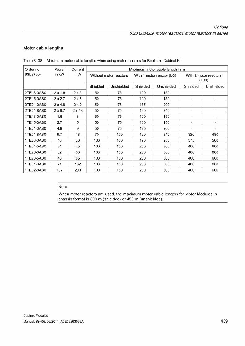
Options 8.23 L08/L09, motor reactor/2 motor reactors in series
Cabinet Modules Manual, (GH5), 03/2011, A5E03263538A 439
Motor cable lengths
Table 8- 38 Maximum motor cable lengths when using motor reactors for Booksize Cabinet Kits
Maximum motor cable length in m Without motor reactors With 1 motor reactor (L08) With 2 motor reactors
(L09)
Order no. 6SL3720-
Power in kW
Current in A
Shielded Unshielded Shielded Unshielded Shielded Unshielded 2TE13-0AB0 2 x 1.6 2 x 3 50 75 100 150 - - 2TE15-0AB0 2 x 2.7 2 x 5 50 75 100 150 - - 2TE21-0AB0 2 x 4.8 2 x 9 50 75 135 200 - - 2TE21-8AB0 2 x 9.7 2 x 18 50 75 160 240 - - 1TE13-0AB0 1.6 3 50 75 100 150 - - 1TE15-0AB0 2.7 5 50 75 100 150 - - 1TE21-0AB0 4.8 9 50 75 135 200 - - 1TE21-8AB0 9.7 18 70 100 160 240 320 480 1TE23-0AB0 16 30 100 150 190 280 375 560 1TE24-5AB0 24 45 100 150 200 300 400 600 1TE26-0AB0 32 60 100 150 200 300 400 600 1TE28-5AB0 46 85 100 150 200 300 400 600 1TE31-3AB0 71 132 100 150 200 300 400 600 1TE32-8AB0 107 200 100 150 200 300 400 600
Note
When motor reactors are used, the maximum motor cable lengths for Motor Modules in chassis format is 300 m (shielded) or 450 m (unshielded).
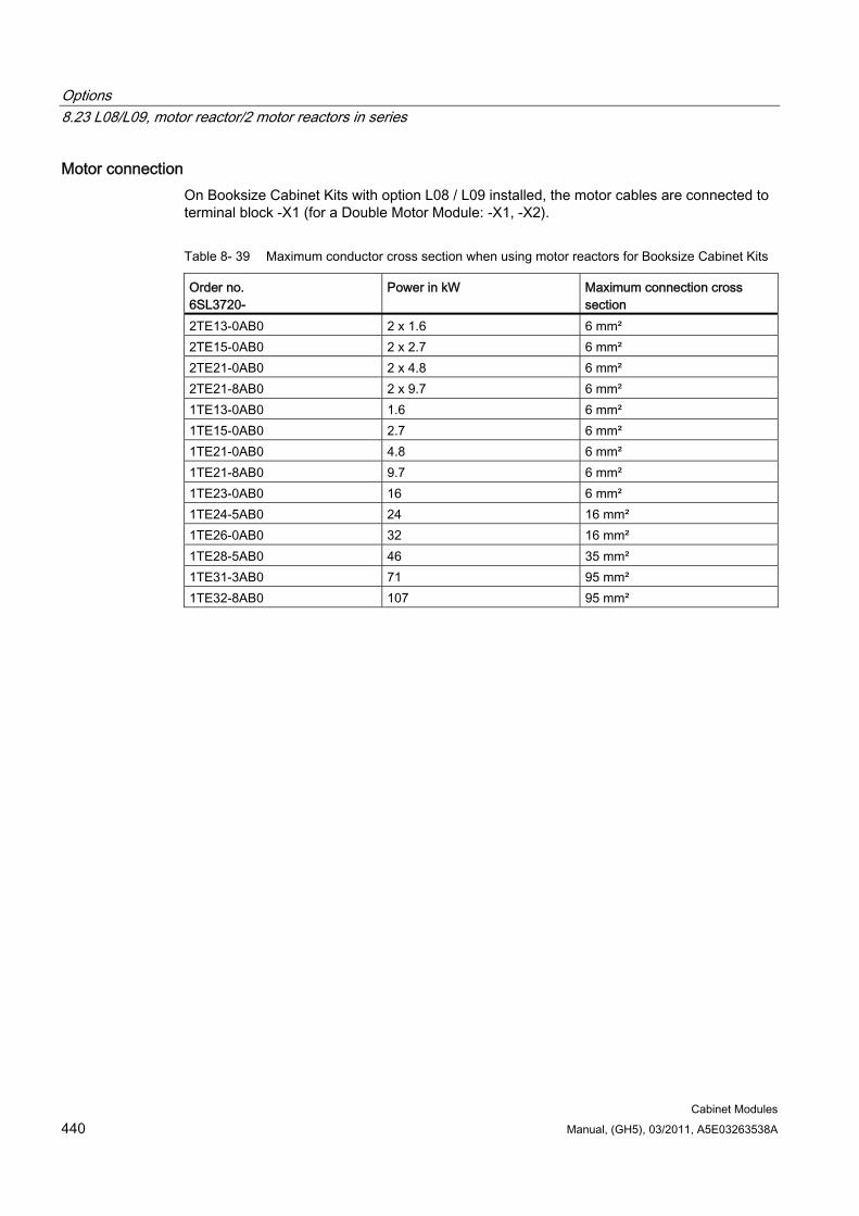
Options 8.23 L08/L09, motor reactor/2 motor reactors in series
Cabinet Modules 440 Manual, (GH5), 03/2011, A5E03263538A
Motor connection On Booksize Cabinet Kits with option L08 / L09 installed, the motor cables are connected to terminal block -X1 (for a Double Motor Module: -X1, -X2).
Table 8- 39 Maximum conductor cross section when using motor reactors for Booksize Cabinet Kits
Order no. 6SL3720-
Power in kW Maximum connection cross section
2TE13-0AB0 2 x 1.6 6 mm² 2TE15-0AB0 2 x 2.7 6 mm² 2TE21-0AB0 2 x 4.8 6 mm² 2TE21-8AB0 2 x 9.7 6 mm² 1TE13-0AB0 1.6 6 mm² 1TE15-0AB0 2.7 6 mm² 1TE21-0AB0 4.8 6 mm² 1TE21-8AB0 9.7 6 mm² 1TE23-0AB0 16 6 mm² 1TE24-5AB0 24 16 mm² 1TE26-0AB0 32 16 mm² 1TE28-5AB0 46 35 mm² 1TE31-3AB0 71 95 mm² 1TE32-8AB0 107 95 mm²
Options 8.24 L10, dv/dt filter plus Voltage Peak Limiter
Cabinet Modules Manual, (GH5), 03/2011, A5E03263538A 441
8.24 L10, dv/dt filter plus Voltage Peak Limiter
Availability of option This option is available for the following S120 Cabinet Modules:
Chassis format Motor Modules
Description The dv/dt filter plus Voltage Peak Limiter comprises two components: the dv/dt reactor and the voltage-limiting network (Voltage Peak Limiter), which limits the voltage peaks to the level of the DC link voltage and returns energy to the DC link.
The dv/dt filters plus Voltage Peak Limiter must be used for motors for which the proof voltage of the insulation system is unknown or insufficient. Standard motors of the 1LA5, 1LA6, and 1LA8 series only require them at supply voltages > 500 V + 10%.
The dv/dt filter plus Voltage Peak Limiter limits the voltage gradient to values < 500 V/µs and the typical voltage peaks to the values below (for motor cable lengths of < 300 m for frame sizes FX, GX, HX or < 150 m for frame size JX):
< 1000 V at Uline < 575 V
< 1250 V at 660 V < Uline < 690 V.
Option L10 is installed in an additional cabinet with a width of 600 mm that is located on the right-hand side of the Motor Module.
WARNING When a dV/dt filter plus Voltage Peak Limiter is used, the pulse frequency of the Power Module must not exceed 2.5 kHz or 4 kHz. If a higher pulse frequency is set, then this could destroy the dV/dt filter.
CAUTION When a dV/dt filter plus Voltage Peak Limiter is used, the drive must not be operated without a connected motor, otherwise the filter can be destroyed.
Note
It is permissible to set pulse frequencies in the range between the rated pulse frequency and the relevant maximum pulse frequency when a dV/dt filter plus Voltage Peak Limiter is used. When doing so, take into account the "Current derating as a function of the pulse frequency; refer to the Technical data.
Note
Parts of option L10 do not have nickel-plated copper busbars.
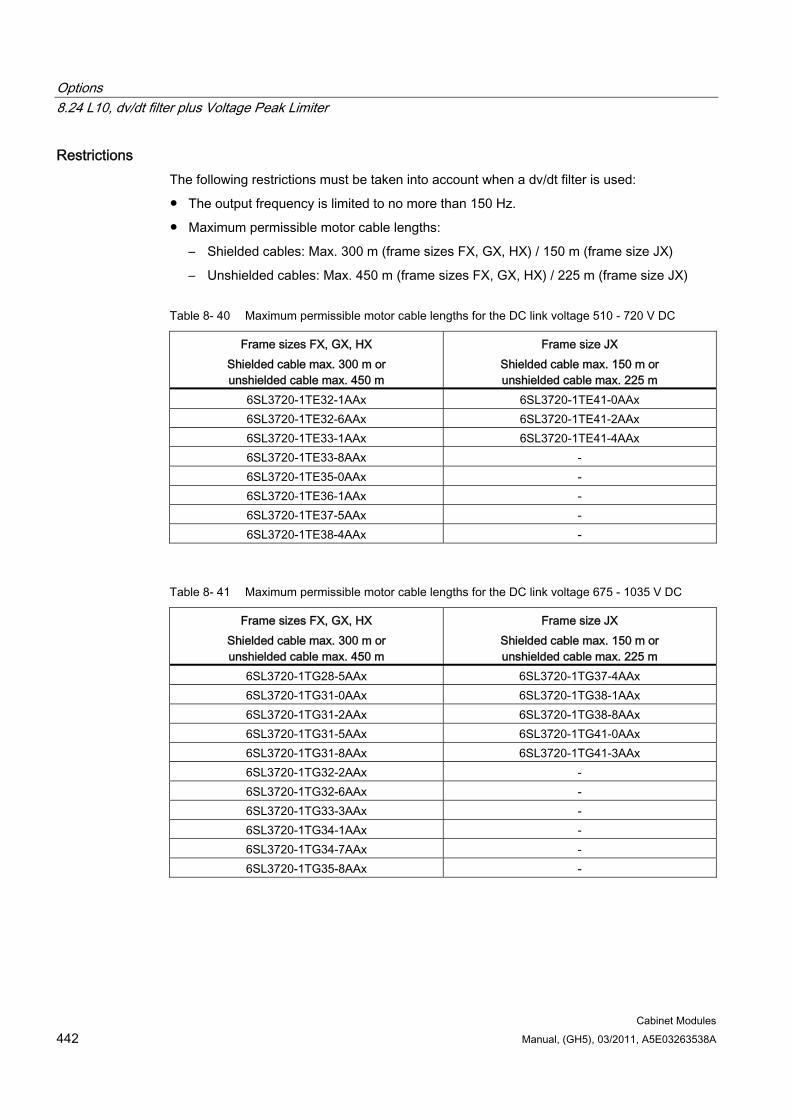
Options 8.24 L10, dv/dt filter plus Voltage Peak Limiter
Cabinet Modules 442 Manual, (GH5), 03/2011, A5E03263538A
Restrictions The following restrictions must be taken into account when a dv/dt filter is used:
The output frequency is limited to no more than 150 Hz.
Maximum permissible motor cable lengths:
– Shielded cables: Max. 300 m (frame sizes FX, GX, HX) / 150 m (frame size JX)
– Unshielded cables: Max. 450 m (frame sizes FX, GX, HX) / 225 m (frame size JX)
Table 8- 40 Maximum permissible motor cable lengths for the DC link voltage 510 - 720 V DC
Frame sizes FX, GX, HX Shielded cable max. 300 m or unshielded cable max. 450 m
Frame size JX Shielded cable max. 150 m or unshielded cable max. 225 m
6SL3720-1TE32-1AAx 6SL3720-1TE41-0AAx 6SL3720-1TE32-6AAx 6SL3720-1TE41-2AAx 6SL3720-1TE33-1AAx 6SL3720-1TE41-4AAx 6SL3720-1TE33-8AAx - 6SL3720-1TE35-0AAx - 6SL3720-1TE36-1AAx - 6SL3720-1TE37-5AAx - 6SL3720-1TE38-4AAx -
Table 8- 41 Maximum permissible motor cable lengths for the DC link voltage 675 - 1035 V DC
Frame sizes FX, GX, HX Shielded cable max. 300 m or unshielded cable max. 450 m
Frame size JX Shielded cable max. 150 m or unshielded cable max. 225 m
6SL3720-1TG28-5AAx 6SL3720-1TG37-4AAx 6SL3720-1TG31-0AAx 6SL3720-1TG38-1AAx 6SL3720-1TG31-2AAx 6SL3720-1TG38-8AAx 6SL3720-1TG31-5AAx 6SL3720-1TG41-0AAx 6SL3720-1TG31-8AAx 6SL3720-1TG41-3AAx 6SL3720-1TG32-2AAx - 6SL3720-1TG32-6AAx - 6SL3720-1TG33-3AAx - 6SL3720-1TG34-1AAx - 6SL3720-1TG34-7AAx - 6SL3720-1TG35-8AAx -
Options 8.25 L13, main contactor for Line Connection Modules < 800 A
Cabinet Modules Manual, (GH5), 03/2011, A5E03263538A 443
Commissioning During commissioning, the dv/dt filter must be logged on using STARTER or via the AOP30 operator panel (p0230 = 2).
Note
Parameter p0230 is reset when the factory setting is established. The parameter has to be reset when recommissioning.
8.25 L13, main contactor for Line Connection Modules < 800 A
Availability of option This option is available for the following S120 Cabinet Modules:
Line Connection Modules
Description The Line Connection Modules with option L43 (for Basic Line Modules) include a manual fuse switch disconnector as a standard feature for rated currents up to 800 A. Option L13 is needed if a switching element is also required for disconnecting the cabinet from the infeed. In this case, the contactor is activated from the connected Line Module.
In conjunction with option L42 (for Active Line Module):
– For a rated current < 605 A (380 to 480 V 3 AC) or < 575 A (500 to 690 V 3 AC), the main contactor is a standard feature in the Active Interface Module of the Active Line Module.
– For a rated current of 605 A (380 to 480 V 3 AC) or 575 A and 730 A (500 to 690 V 3 AC), option L13 (main contactor) is a standard feature in the Line Connection Module.
– For a rated current > 605 A (380 to 480 V 3 AC) or > 730 A (500 to 690 V 3 AC), a circuit breaker is a standard feature in the Line Connection Module.
In conjunction with option L43 (for Basic Line Module):
– For a rated current < 800 A, option L13 (main contactor) can be ordered.
– For a rated current > 800 A, a circuit breaker is a standard feature in the Line Connection Module.
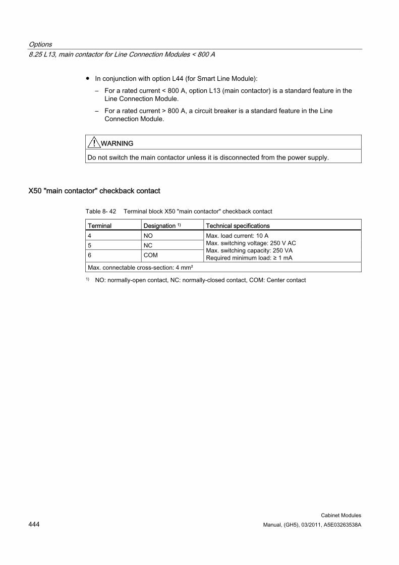
Options 8.25 L13, main contactor for Line Connection Modules < 800 A
Cabinet Modules 444 Manual, (GH5), 03/2011, A5E03263538A
In conjunction with option L44 (for Smart Line Module):
– For a rated current < 800 A, option L13 (main contactor) is a standard feature in the Line Connection Module.
– For a rated current > 800 A, a circuit breaker is a standard feature in the Line Connection Module.
WARNING Do not switch the main contactor unless it is disconnected from the power supply.
X50 "main contactor" checkback contact
Table 8- 42 Terminal block X50 "main contactor" checkback contact
Terminal Designation 1) Technical specifications 4 NO 5 NC 6 COM
Max. load current: 10 A Max. switching voltage: 250 V AC Max. switching capacity: 250 VA Required minimum load: ≥ 1 mA
Max. connectable cross-section: 4 mm²
1) NO: normally-open contact, NC: normally-closed contact, COM: Center contact
Options 8.26 L22, supplied as standard without line reactor
Cabinet Modules Manual, (GH5), 03/2011, A5E03263538A 445
8.26 L22, supplied as standard without line reactor
Availability of option This option is available for the following S120 Cabinet Modules:
Line Connection Modules, only with option L43 (for Basic Line Modules)
Smart Line Modules
Description If the Basic Line Module or Smart Line Module is supplied via a separate transformer, or if the supply system has a sufficiently low supply short-circuit power, the standard line reactor can be omitted.
For the Line Connection Module with option L22, the standard line reactor is not supplied in conjunction with the Basic Line Module (option L43).
The Smart Line Module with option L22 is supplied without a standard line reactor.
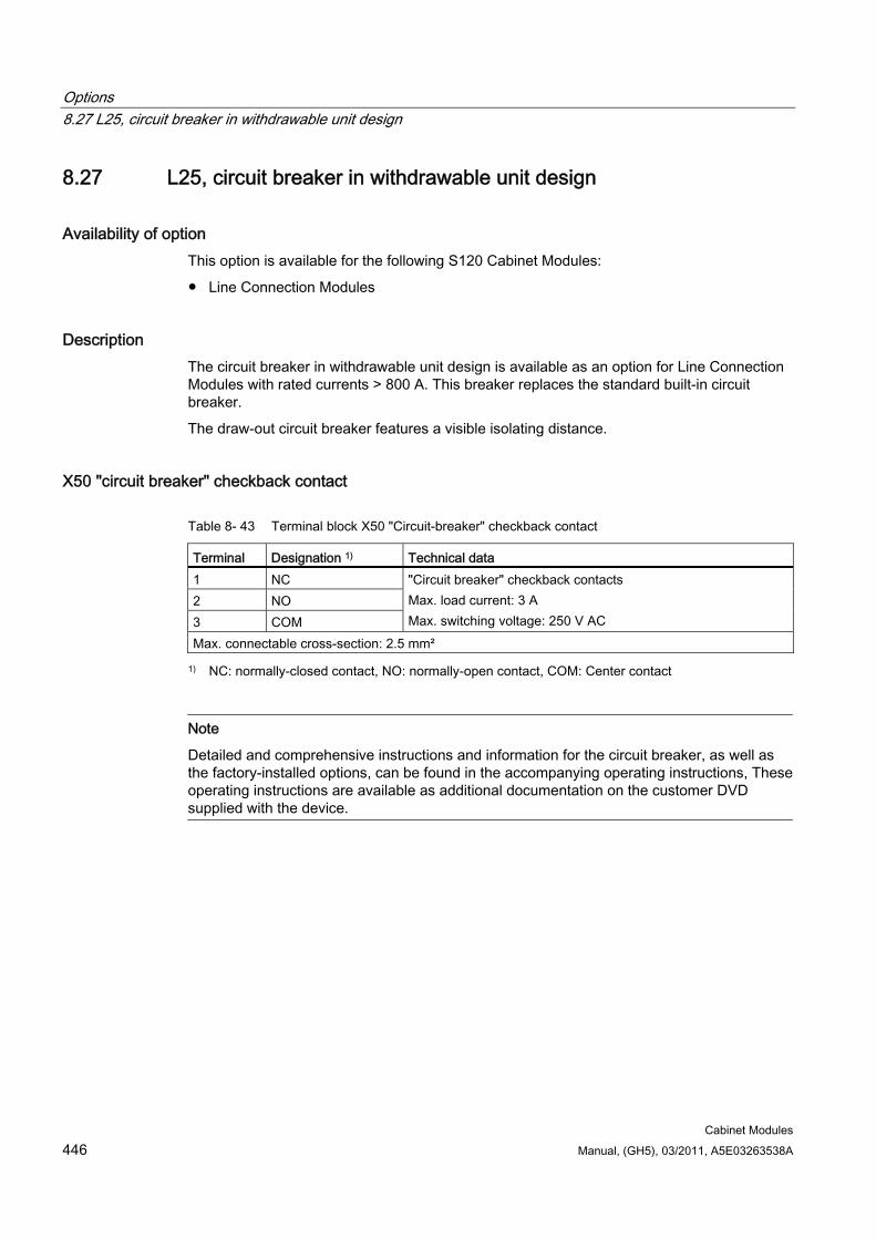
Options 8.27 L25, circuit breaker in withdrawable unit design
Cabinet Modules 446 Manual, (GH5), 03/2011, A5E03263538A
8.27 L25, circuit breaker in withdrawable unit design
Availability of option This option is available for the following S120 Cabinet Modules:
Line Connection Modules
Description The circuit breaker in withdrawable unit design is available as an option for Line Connection Modules with rated currents > 800 A. This breaker replaces the standard built-in circuit breaker.
The draw-out circuit breaker features a visible isolating distance.
X50 "circuit breaker" checkback contact
Table 8- 43 Terminal block X50 "Circuit-breaker" checkback contact
Terminal Designation 1) Technical data 1 NC 2 NO 3 COM
"Circuit breaker" checkback contacts Max. load current: 3 A Max. switching voltage: 250 V AC
Max. connectable cross-section: 2.5 mm²
1) NC: normally-closed contact, NO: normally-open contact, COM: Center contact
Note
Detailed and comprehensive instructions and information for the circuit breaker, as well as the factory-installed options, can be found in the accompanying operating instructions, These operating instructions are available as additional documentation on the customer DVD supplied with the device.
Options 8.28 L34, output-side circuit breaker
Cabinet Modules Manual, (GH5), 03/2011, A5E03263538A 447
8.28 L34, output-side circuit breaker
8.28.1 General information
Availability of option This option is available for the following S120 Cabinet Modules:
Chassis format Motor Modules
Description The option L34 (output-side circuit breaker) can be used to disconnect the motor terminals from the converter.
It is pre-wired and installed in a separate cabinet.
WARNING
At the motor terminals, a rotating, permanent-field synchronous motor generates a voltage that is proportional to the speed. The motor terminal voltage is always applied to the converter output terminals, the DC link and the connected components. Option L34 can be used to isolate a circuit in the event of a fault, or for maintenance work.
Note
Detailed and comprehensive instructions and information for the circuit breaker can be found in the supplementary option description. This description is available as additional documentation on the customer DVD supplied with the device.
The Option L34 (output-side circuit breaker) is required in the following applications where permanent-field motors are used:
Drives with a high moment of inertia, which require a longer period of time to coast down and generate a voltage at the motor terminals during this time.
Mechanically coupled auxiliary drives, which can be driven together by a main drive.
When carrying out maintenance and repairs on a converter if the motor cannot be stopped safely (e.g. using a mechanical brake).
During high field weakening in conjunction with a suitable level of overvoltage protection, which suppresses the applied overvoltage effectively until the switch trips.
Options 8.28 L34, output-side circuit breaker
Cabinet Modules 448 Manual, (GH5), 03/2011, A5E03263538A
Features Option L34 is completely pre-wired. It is controlled using a built-in TM31 Terminal Module. To control this, the parameterization specified in the following Chapter "Parameterization" must be made during commissioning.
Note
After setting the parameters, the user must ensure that the switch is operating correctly.
For this reason, the output-side breaker is automatically controlled via the converter.
Note
The "ON" pushbutton directly located at the output switch is only available with the full functional scope, if the following preconditions are fulfilled: there is no alarm or fault present, the customer remote-OFF is set to "enable".
To close the output-side breaker, the following conditions must be fulfilled:
There must be no faults on the Motor Module.
There must be no OFF command active on the Motor Module.
The Motor Module must receive an ON command.
Pre-charging of the Motor Module must be complete.
The output-side breaker is opened under the following conditions:
There is an active fault on the Motor Module.
The power supply at the auxiliary power system for option L34 (230 V AC/24 V DC) fails.
The local “OFF” button on the output-side breaker is pressed.
Note
Pressing the “OFF” button directly on the output-side breaker will switch the Motor Module off (pulse suppression). The converter displays "External fault 3". The breaker can be closed again only by sending a new ON command via the Motor Module.
Note
To reduce the number of switching cycles, the output-side breaker will not open if the Motor Module receives an “OFF” command (OFF1, OFF2, OFF3).
If they are available, remote off switches (for optional use by customers) for disconnecting the output-side breaker must be connected accordingly via the undervoltage coil.
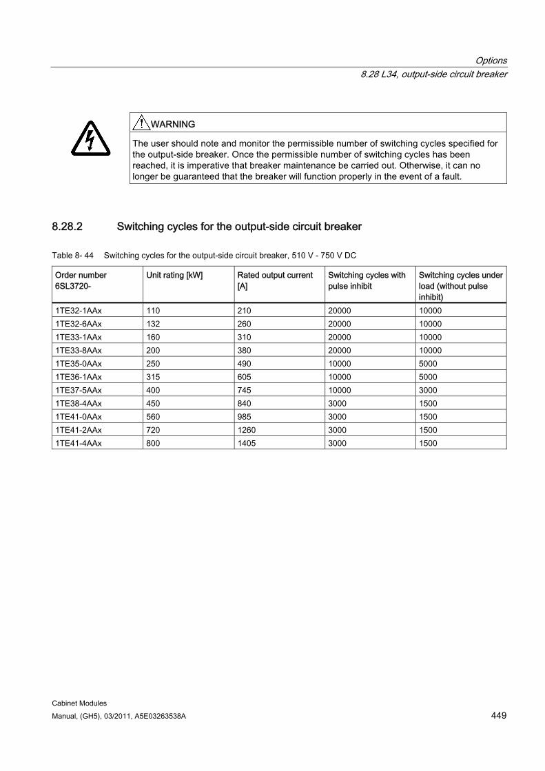
Options 8.28 L34, output-side circuit breaker
Cabinet Modules Manual, (GH5), 03/2011, A5E03263538A 449
WARNING
The user should note and monitor the permissible number of switching cycles specified for the output-side breaker. Once the permissible number of switching cycles has been reached, it is imperative that breaker maintenance be carried out. Otherwise, it can no longer be guaranteed that the breaker will function properly in the event of a fault.
8.28.2 Switching cycles for the output-side circuit breaker
Table 8- 44 Switching cycles for the output-side circuit breaker, 510 V - 750 V DC
Order number 6SL3720-
Unit rating [kW] Rated output current [A]
Switching cycles with pulse inhibit
Switching cycles under load (without pulse inhibit)
1TE32-1AAx 110 210 20000 10000 1TE32-6AAx 132 260 20000 10000 1TE33-1AAx 160 310 20000 10000 1TE33-8AAx 200 380 20000 10000 1TE35-0AAx 250 490 10000 5000 1TE36-1AAx 315 605 10000 5000 1TE37-5AAx 400 745 10000 3000 1TE38-4AAx 450 840 3000 1500 1TE41-0AAx 560 985 3000 1500 1TE41-2AAx 720 1260 3000 1500 1TE41-4AAx 800 1405 3000 1500
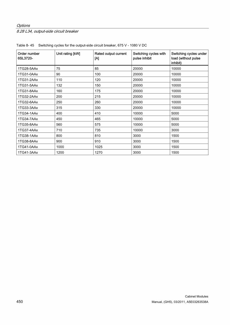
Options 8.28 L34, output-side circuit breaker
Cabinet Modules 450 Manual, (GH5), 03/2011, A5E03263538A
Table 8- 45 Switching cycles for the output-side circuit breaker, 675 V - 1080 V DC
Order number 6SL3720-
Unit rating [kW] Rated output current [A]
Switching cycles with pulse inhibit
Switching cycles under load (without pulse inhibit)
1TG28-5AAx 75 85 20000 10000 1TG31-0AAx 90 100 20000 10000 1TG31-2AAx 110 120 20000 10000 1TG31-5AAx 132 150 20000 10000 1TG31-8AAx 160 175 20000 10000 1TG32-2AAx 200 215 20000 10000 1TG32-6AAx 250 260 20000 10000 1TG33-3AAx 315 330 20000 10000 1TG34-1AAx 400 410 10000 5000 1TG34-7AAx 450 465 10000 5000 1TG35-8AAx 560 575 10000 5000 1TG37-4AAx 710 735 10000 3000 1TG38-1AAx 800 810 3000 1500 1TG38-8AAx 900 910 3000 1500 1TG41-0AAx 1000 1025 3000 1500 1TG41-3AAx 1200 1270 3000 1500
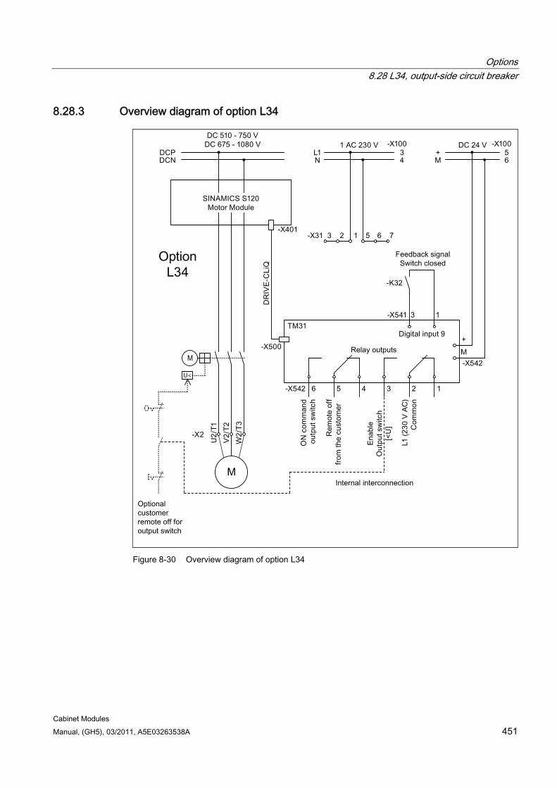
Options 8.28 L34, output-side circuit breaker
Cabinet Modules Manual, (GH5), 03/2011, A5E03263538A 451
8.28.3 Overview diagram of option L34
<
Figure 8-30 Overview diagram of option L34
Options 8.28 L34, output-side circuit breaker
Cabinet Modules 452 Manual, (GH5), 03/2011, A5E03263538A
8.28.4 Parameter assignment
8.28.4.1 Parameterization with script A script can be used for the automatic parameterization, which automatically makes the parameter settings in STARTER. The script and the handling instructions for executing the script are provided on the customer DVD, which is supplied with the device when it is shipped.
Note Script
The script and the handling instructions for executing the script are provided on the customer DVD in folder "99 SOFTWARE\SCRIPT_option_L34". The customer DVD is supplied with the device when it is shipped.
8.28.4.2 Parameterization with free function blocks The free function blocks are used for the parameterization described in this section. You must start by activating them.
Activating the free function blocks To be able to work with the free function blocks, they must first be activated/enabled:
If you are not certain that the project in the STARTER corresponds to the drive configuration, you should start with an upload (load data to PG).
In Offline mode -> Right-click the drive object -> Properties -> Activate the “Free function blocks” in the “Drive Properties” interactive screenform under “Select function modules”.
You will then need to perform a download (load data to the target device) so that the “Free function blocks” function module is activated in the drive.
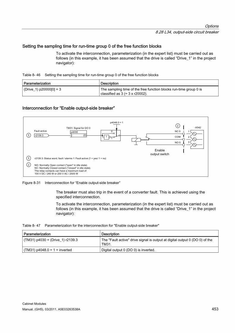
Options 8.28 L34, output-side circuit breaker
Cabinet Modules Manual, (GH5), 03/2011, A5E03263538A 453
Setting the sampling time for run-time group 0 of the free function blocks To activate the interconnection, parameterization (in the expert list) must be carried out as follows (in this example, it has been assumed that the drive is called “Drive_1” in the project navigator):
Table 8- 46 Setting the sampling time for run-time group 0 of the free function blocks
Parameterization Description (Drive_1) p20000[0] = 3 The sampling time of the free function blocks run-time group 0 is
classified as 3 (= 3 x r20002).
Interconnection for “Enable output-side breaker”
Figure 8-31 Interconnection for “Enable output-side breaker”
The breaker must also trip in the event of a converter fault. This is achieved using the specified interconnection.
To activate the interconnection, parameterization (in the expert list) must be carried out as follows (in this example, it has been assumed that the drive is called “Drive_1” in the project navigator):
Table 8- 47 Parameterization for the interconnection for "Enable output-side breaker"
Parameterization Description (TM31) p4030 = (Drive_1) r2139.3 The "Fault active" drive signal is output at digital output 0 (DO 0) of the
TM31. (TM31) p4048.0 = 1 = inverted Digital output 0 (DO 0) is inverted.
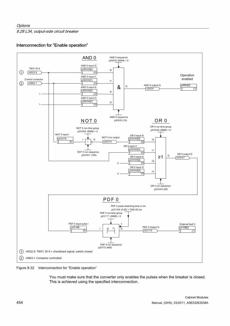
Options 8.28 L34, output-side circuit breaker
Cabinet Modules 454 Manual, (GH5), 03/2011, A5E03263538A
Interconnection for “Enable operation”
Figure 8-32 Interconnection for “Enable operation”
You must make sure that the converter only enables the pulses when the breaker is closed. This is achieved using the specified interconnection.
Options 8.28 L34, output-side circuit breaker
Cabinet Modules Manual, (GH5), 03/2011, A5E03263538A 455
To activate the interconnection, parameterization (in the expert list) must be carried out as follows (in this example, it has been assumed that the drive is called “Drive_1” in the project navigator):
Table 8- 48 Parameterization for the interconnection for "Operation enabled"
Parameterization Description (Drive_1) p20161 = 0 The "switch on delay 0 (PDE 0)" function block is assigned to run-time
group 0. (Drive_1) p20158 = (Drive_1) r0863.1 Input pulse I of the function block "Switch on delay 0 (PDE 0)" of the drive
is interconnected using the "control contactor" drive signal. (Drive_1) p20159 = 4000.00 The pulse delay time of function block "Switch on delay 0 (PDE 0) of the
drive is set to 4000.00 ms. (Drive_1) p20146 = 0 The "Pulse generator 1 (MFP 1)" function block is assigned to run-time
group 0. (Drive_1) p20143 = (Drive_1) r20160 Input pulse I of function block "Pulse generator 1 (MFP 1)" is
interconnected with output Q of function block "Switch on delay 0 (PDE 0)".(Drive_1) p20144 = 5000.00 The pulse duration of the "Pulse generator 1 (MFP 1)" function block is set
to 5000.00 ms. (Drive_1) p20048 = 0 The "OR 0" function block is assigned to run-time group 0. (Drive_1) p20046[0] = (Drive_1) r20145 Output pulse Q of function block "Pulse generator 1 (MFP 1)" of the drive is
interconnected at input I0 of the "OR 0" function block. (Drive_1) p20046[1] = (TM31) r4022.9 Input signal DI9, terminal X541.3 of TM31 is interconnected at input I1 of
function block "OR 0". (Drive_1) p20046[2] = 0 A "0" signal is interconnected at input I2 of function block "OR 0" (Drive_1) p20046[3] = 0 A "0" signal is interconnected at input I3 of function block "OR 0". (Drive_1) p20032 = 0 The "AND 0" function block is assigned to run-time group 0. (Drive_1) p20030[0] = (Drive_1) r20047 Output signal Q of function block "OR 0" of the drive is interconnected at
input I0 of function block "AND 0" of the drive. (Drive_1) p20030[1] = (Drive_1) r0863.1 The "control contactor" signal of the drive is interconnected at input I1 of
the "AND 0" function block of the drive. (Drive_1) p20030[2] = 1 A "1" signal is interconnected at input I2 of function block "AND 0" of the
drive. (Drive_1) p20030[3] = 1 A "1" signal is interconnected at input I3 of function block "AND 0" of the
drive. (Drive_1) p0860[0] = (Drive_1) r20031 The output signal of the "AND 0" function block of the drive is used for the
"Line contactor feedback" signal of the drive. (Drive_1) p0852[0] = (TM31) r4022.9 Input signal DI9, terminal X541.3 of TM31 is used for the signal "enable
operation" of the drive. (Drive_1) p0861 = 5000 The monitoring time of the line contactor is set to 5000 ms.
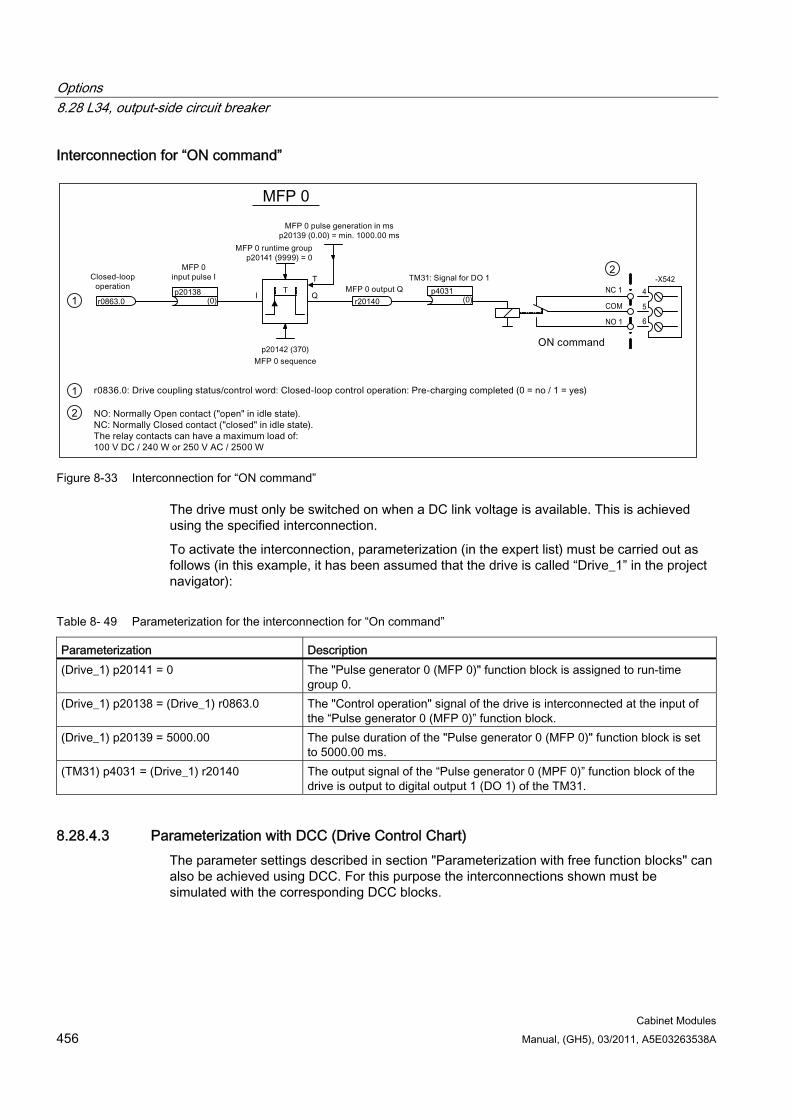
Options 8.28 L34, output-side circuit breaker
Cabinet Modules 456 Manual, (GH5), 03/2011, A5E03263538A
Interconnection for “ON command”
Figure 8-33 Interconnection for “ON command”
The drive must only be switched on when a DC link voltage is available. This is achieved using the specified interconnection.
To activate the interconnection, parameterization (in the expert list) must be carried out as follows (in this example, it has been assumed that the drive is called “Drive_1” in the project navigator):
Table 8- 49 Parameterization for the interconnection for “On command”
Parameterization Description (Drive_1) p20141 = 0 The "Pulse generator 0 (MFP 0)" function block is assigned to run-time
group 0. (Drive_1) p20138 = (Drive_1) r0863.0 The "Control operation" signal of the drive is interconnected at the input of
the “Pulse generator 0 (MFP 0)” function block. (Drive_1) p20139 = 5000.00 The pulse duration of the "Pulse generator 0 (MFP 0)" function block is set
to 5000.00 ms. (TM31) p4031 = (Drive_1) r20140 The output signal of the “Pulse generator 0 (MPF 0)” function block of the
drive is output to digital output 1 (DO 1) of the TM31.
8.28.4.3 Parameterization with DCC (Drive Control Chart) The parameter settings described in section "Parameterization with free function blocks" can also be achieved using DCC. For this purpose the interconnections shown must be simulated with the corresponding DCC blocks.
Options 8.29 L37, DC interface incl. pre-charging input circuit for the relevant DC link capacitance
Cabinet Modules Manual, (GH5), 03/2011, A5E03263538A 457
8.29 L37, DC interface incl. pre-charging input circuit for the relevant DC link capacitance
8.29.1 General information
Availability of option This option is available for the following S120 Cabinet Modules:
Booksize Cabinet Kits
Chassis format Motor Modules
Description If the Motor Module is to be disconnected or reconnected to the DC link of a drive line-up while the other Motor Modules and Line Modules remain in operation, this can be accomplished via the DC interface.
8.29.2 DC interface incl. pre-charging for Booksize Cabinet Kits
8.29.2.1 Important safety precautions The Motor Module can be serviced after it has been disconnected from the DC busbar via the DC interface and after the capacitor discharge time has elapsed. However, the following safety precautions must be observed:
DANGER
Once the DC busbar and the Motor Module in booksize format have been disconnected by means of the fuse switch disconnector (-Q7), the following voltages continue to be present in the adjacent Motor Modules in booksize format in the Cabinet Module: Up to 800 V on the DC busbar (protected against accidental contact) Line voltage (3 AC 380 ... 480 V) via the auxiliary power supply system or 2 AC 230 V
downstream of the transformers for the fan supply Up to 230 V AC via the auxiliary power supply system or via direct infeed for SITOP and
fan supply 24 V DC on the auxiliary power supply system (electronics power supply) On the motor connection (e.g. regenerative voltage due to residual speed)
Options 8.29 L37, DC interface incl. pre-charging input circuit for the relevant DC link capacitance
Cabinet Modules 458 Manual, (GH5), 03/2011, A5E03263538A
WARNING
The cabinet units are operated with high voltages.
All connection work must be carried out when the cabinet is de-energized.
All work on the cabinet must be carried out by trained personnel only.
Work on an open cabinet must be carried out with extreme caution because external supply voltages may be present. The power and control terminals may be live even when the motor is not running.
Due to the DC link capacitors, dangerously high voltage levels are still present inside the cabinet up to 5 minutes after it has been disconnected. For this reason, the cabinet should not be opened until a reasonable period of time has elapsed.
For this reason, you must take the following safety precautions when carrying out work on the Cabinet Module after the DC interface has been switched off:
Observe the "five safety rules" for all electrical work.
Only commission qualified specialists to carry out the work.
Ensure that no voltage is present at the measuring points provided in the cabinet.
Check that there is no voltage on the motor connections.
When working close to the DC busbar in the cabinet, take care to avoid any contact with the DC busbar.
When replacing components, make sure that no screws or small parts fall into the cabinet.
Remove the fan fuse and fuse for the 24 V DC power supply.
NOTICE You must observe the applicable legal regulations when carrying out all work.
DANGER
The following voltages are normally present on the auxiliary power supply system: 380 to 480 V 2 AC for fan supply 230 V 1 AC 24 V DC for electronics power supply
Options 8.29 L37, DC interface incl. pre-charging input circuit for the relevant DC link capacitance
Cabinet Modules Manual, (GH5), 03/2011, A5E03263538A 459
8.29.2.2 DC interface, principle of operation The DC interface connects/disconnects the DC busbar and the Motor Module in the Cabinet Kit. This option is implemented with a pre-charging input circuit. A fuse switch disconnector, which is installed as a standard feature between the Motor Module and the DC busbar, as well as pre-charging resistors and contactor disconnectors connect the Motor Module with the DC busbar.
The contactor disconnector is triggered via a time relay, which is activated by the switch installed in the door.
CAUTION The DC interface should only be switched and the fuse switch disconnector should only be unplugged when not under load. A checkback signal is transferred via the internal interconnection to the CU320-2 Control Unit which locks out switching under load.
8.29.2.3 Commissioning the DC interface with option K90/K95 With option K90/K95, a feedback signal contact from the fuse switch disconnector is connected to digital input 3 of the Control Unit (this connection is realized in the factory).
CAUTION If changes are made to the factory-set parameters, you must verify that the "Infeed ready" checkback signal is connected to digital input 3 on the Control Unit (p0864 = r722.3).
If parameter p0864 is not wired to the checkback signal, it is possible to operate the switch under load. This can shorten the service life of the switch.
8.29.2.4 Commissioning the DC coupling without option K90/K95 If the cabinet does not contain a Control Unit (option K90 / K95), terminal -X41.12 of the DC coupling must be connected by the customer to a digital input of the Control Unit assigned to the controlled Motor Module. The 24 V DC supply for the checkback signal is provided via terminal -X41.11 (see circuit diagram).
The digital input to which the checkback contact is assigned must be connected to the "Infeed operation" parameter (p0864) of the drive object [Drive_1].
Example of digital input 3 on the Control Unit:
[Drive_1] p0864 = [CU] r722.3
The interconnection can be made with the STARTER commissioning tool or the AOP30 operator panel (option K08).
Options 8.29 L37, DC interface incl. pre-charging input circuit for the relevant DC link capacitance
Cabinet Modules 460 Manual, (GH5), 03/2011, A5E03263538A
CAUTION If parameter p0864 is not wired to the checkback signal, it is possible to operate the switch under load. This can shorten the service life of the switch.
Note
The digital input parameter assignment is described in the List Manual and S120 Commissioning Manual.
8.29.3 DC interface incl. pre-charging for Motor Modules in the chassis format The main component of option L37 is a switch disconnector. This switch disconnector is installed on the busbar between the Motor Module and the DC busbar. This option also includes a pre-charging switch for the DC link capacitors of the relevant Motor Module so that it can be switched in to the pre-charged DC busbar.
This switch can be actuated using an operating lever but only when the cabinet door is closed.
As an air guide, option L37 also includes option M60 (additional shock protection).
Note
This option is not used for switching the module on and off during operation.
Frame sizes FX and GX each contain two fuses, while frame size JX contains four fuses. Depending on the current carrying capacity, frame size HX contains either two or four fuses.
Four pre-charging resistors are also used in frame size JX for higher power ratings. For more detailed information, see the circuit diagrams.
Note
With option K90 (Control Unit), a checkback contact is wired from terminal -X41:12 to digital input 3 on customer terminal block -X55 to commission the DC interface via parameter interconnection (see "Commissioning the DC interface"). A jumper to the reference potential is also used.
Options 8.29 L37, DC interface incl. pre-charging input circuit for the relevant DC link capacitance
Cabinet Modules Manual, (GH5), 03/2011, A5E03263538A 461
8.29.3.1 Important safety precautions The Motor Module can be serviced after it has been disconnected from the DC busbar via the DC interface and after the capacitor discharge time has elapsed. However, the following safety precautions must be observed:
DANGER
Once the DC busbar and the Motor Module have been disconnected using the DC interface (-Q7), the following voltages may be present in the Cabinet Module: Up to 1200 V on the DC busbar (protected against accidental contact) Line voltage (3 AC 380 V ... 480 V or 500 V ... 690 V) on the auxiliary power supply
system or 2 AC 230 V downstream of the transformers for the fan supply Up to 230 V AC on the optional mounting locations 24 V DC on the auxiliary power supply system (electronics power supply) On motor connection -X2 (e.g. regenerative voltage due to residual speed)
WARNING
The cabinet units are operated with high voltages. All connection work must be carried out when the cabinet is de-energized. All work on the cabinet must be carried out by trained personnel only.
Work on an open cabinet must be carried out with extreme caution because external supply voltages may be present. The power and control terminals may be live even when the motor is not running.
Due to the DC link capacitors, dangerously high voltage levels are still present inside the cabinet up to 5 minutes after it has been disconnected. For this reason, the cabinet should not be opened until a reasonable period of time has elapsed.
For this reason, you must take the following safety precautions when carrying out work on the Cabinet Module after the DC interface has been switched off:
Observe the "five safety rules" for all electrical work:
– Disconnect from power supply.
– Protect against reconnection.
– Make sure that the equipment is de-energized.
– Ground and short-circuit.
– Cover or enclose adjacent components that are still live.
Only commission qualified specialists to carry out the work.
Verify that the equipment is de-energized at the measuring points provided in the cabinet (see figures below).
Options 8.29 L37, DC interface incl. pre-charging input circuit for the relevant DC link capacitance
Cabinet Modules 462 Manual, (GH5), 03/2011, A5E03263538A
Check that there is no voltage on the motor connections.
You must avoid coming into contact with the DC busbar when replacing a power block.
When replacing components, make sure that no screws or small parts fall into the cabinet.
Remove the fan fuse and fuse for the 24 V DC power supply.
NOTICE You must observe the applicable legal regulations when carrying out all work.
The following figures show the location of the voltage source once disconnected from the DC busbar and the associated measuring points to verify isolation from the supply in the Cabinet Module.
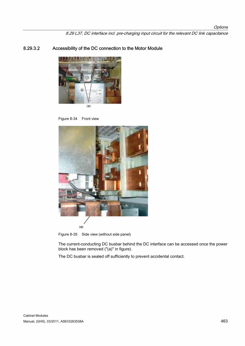
Options 8.29 L37, DC interface incl. pre-charging input circuit for the relevant DC link capacitance
Cabinet Modules Manual, (GH5), 03/2011, A5E03263538A 463
8.29.3.2 Accessibility of the DC connection to the Motor Module
Figure 8-34 Front view
Figure 8-35 Side view (without side panel)
The current-conducting DC busbar behind the DC interface can be accessed once the power block has been removed ("(a)" in figure).
The DC busbar is sealed off sufficiently to prevent accidental contact.
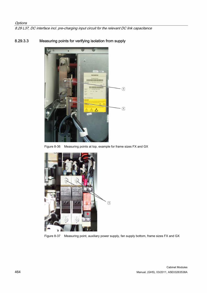
Options 8.29 L37, DC interface incl. pre-charging input circuit for the relevant DC link capacitance
Cabinet Modules 464 Manual, (GH5), 03/2011, A5E03263538A
8.29.3.3 Measuring points for verifying isolation from supply
Figure 8-36 Measuring points at top, example for frame sizes FX and GX
Figure 8-37 Measuring point, auxiliary power supply, fan supply bottom, frame sizes FX and GX
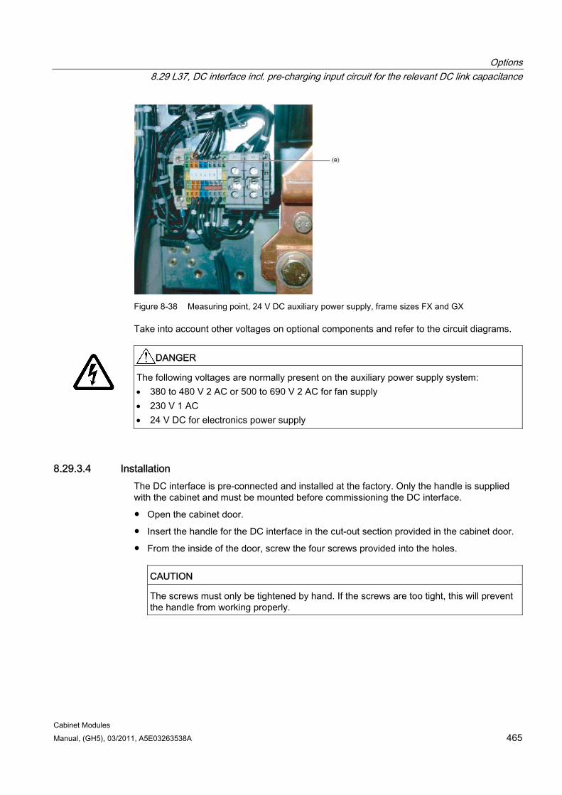
Options 8.29 L37, DC interface incl. pre-charging input circuit for the relevant DC link capacitance
Cabinet Modules Manual, (GH5), 03/2011, A5E03263538A 465
Figure 8-38 Measuring point, 24 V DC auxiliary power supply, frame sizes FX and GX
Take into account other voltages on optional components and refer to the circuit diagrams.
DANGER
The following voltages are normally present on the auxiliary power supply system: 380 to 480 V 2 AC or 500 to 690 V 2 AC for fan supply 230 V 1 AC 24 V DC for electronics power supply
8.29.3.4 Installation The DC interface is pre-connected and installed at the factory. Only the handle is supplied with the cabinet and must be mounted before commissioning the DC interface.
Open the cabinet door.
Insert the handle for the DC interface in the cut-out section provided in the cabinet door.
From the inside of the door, screw the four screws provided into the holes.
CAUTION
The screws must only be tightened by hand. If the screws are too tight, this will prevent the handle from working properly.
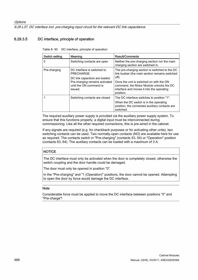
Options 8.29 L37, DC interface incl. pre-charging input circuit for the relevant DC link capacitance
Cabinet Modules 466 Manual, (GH5), 03/2011, A5E03263538A
8.29.3.5 DC interface, principle of operation
Table 8- 50 DC interface, principle of operation
Switch setting Meaning Result/Comments 0 Switching contacts are open Neither the pre-charging section nor the main
charging section are switched in. Pre-charging DC interface is switched to
PRECHARGE. DC link capacitors are loaded. Pre-charging remains activated until the ON command is issued.
The pre-charging section is switched to the DC link busbar (the main section remains switched off). Once the unit is switched on with the ON command, the Motor Module unlocks the DC interface and moves it into the operating position.
1 Switching contacts are closed The DC interface switches to position "1". When the DC switch is in the operating position, the connected auxiliary contacts are switched.
The required auxiliary power supply is provided via the auxiliary power supply system. To ensure that this functions properly, a digital input must be interconnected during commissioning. Like all the other required connections, this is pre-wired in the cabinet.
If any signals are required (e.g. for checkback purposes or for activating other units), two switching contacts can be used. Two normally-open contacts (NO) are available here for use as required. The contacts switch in "Pre-charging" (contacts 53, 54) or "Operation" position (contacts 63, 64). The auxiliary contacts can be loaded with a maximum of 3 A.
NOTICE The DC interface must only be activated when the door is completely closed, otherwise the switch coupling and the door handle could be damaged.
The door must only be opened in position "0".
In the "Pre-charging" and "1 (Operation)" positions, the door cannot be opened. Attempting to open the door by force would damage the DC interface.
Note
Considerable force must be applied to move the DC interface between positions "0" and "Pre-charge"!
Options 8.29 L37, DC interface incl. pre-charging input circuit for the relevant DC link capacitance
Cabinet Modules Manual, (GH5), 03/2011, A5E03263538A 467
8.29.3.6 Commissioning the DC interface when option K90 is being used With option K90, a checkback contact from the switch is factory-linked to digital input 3 of the Control Unit.
CAUTION If changes are made to the factory-set parameters, you must verify that the "Infeed ready" checkback signal is connected to digital input 3 on the Control Unit (p0864 = r722.3).
If parameter p0864 is not wired to the checkback signal, it is possible to operate the switch under load. This can shorten the service life of the switch.
8.29.3.7 Commissioning the DC interface without option K90 If the cabinet does not contain a Control Unit (option K90), terminal -X41:12 of the DC interface must be connected by the customer to a digital input of the Control Unit assigned to the controlled Motor Module.
The digital input to which the checkback contact is assigned must be connected to the "Infeed operation" parameter (p0864) of the drive object [Drive_1].
Example of digital input 3 on the Control Unit [CU]:
[Drive_1] p0864 = [CU] r722.3
The interconnection can be made with the STARTER commissioning tool or the AOP30 operator panel (option K08).
CAUTION If parameter p0864 is not wired to the checkback signal, it is possible to operate the switch under load. This can shorten the service life of the switch.
NOTICE To switch from the "Pre-charging" to the "1 (Operation)" position, a switching current of 4 A / 24 V DC is required for 30 ms. This must be provided via the auxiliary power supply and taken into account during dimensioning (see the block diagram above).
Note
When activating digital inputs, note the guidelines provided in the List Manual and S120 Commissioning Manual.
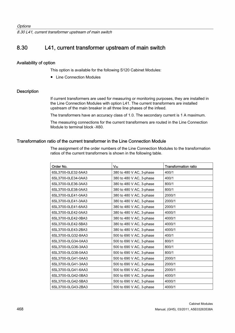
Options 8.30 L41, current transformer upstream of main switch
Cabinet Modules 468 Manual, (GH5), 03/2011, A5E03263538A
8.30 L41, current transformer upstream of main switch
Availability of option This option is available for the following S120 Cabinet Modules:
Line Connection Modules
Description If current transformers are used for measuring or monitoring purposes, they are installed in the Line Connection Modules with option L41. The current transformers are installed upstream of the main breaker in all three line phases of the infeed.
The transformers have an accuracy class of 1.0. The secondary current is 1 A maximum.
The measuring connections for the current transformers are routed in the Line Connection Module to terminal block -X60.
Transformation ratio of the current transformer in the Line Connection Module The assignment of the order numbers of the Line Connection Modules to the transformation ratios of the current transformers is shown in the following table.
Order No. VIN Transformation ratio 6SL3700-0LE32-5AA3 380 to 480 V AC, 3-phase 400/1 6SL3700-0LE34-0AA3 380 to 480 V AC, 3-phase 400/1 6SL3700-0LE36-3AA3 380 to 480 V AC, 3-phase 800/1 6SL3700-0LE38-0AA3 380 to 480 V AC, 3-phase 800/1 6SL3700-0LE41-0AA3 380 to 480 V AC, 3-phase 2000/1 6SL3700-0LE41-3AA3 380 to 480 V AC, 3-phase 2000/1 6SL3700-0LE41-6AA3 380 to 480 V AC, 3-phase 2000/1 6SL3700-0LE42-0AA3 380 to 480 V AC, 3-phase 4000/1 6SL3700-0LE42-0BA3 380 to 480 V AC, 3-phase 4000/1 6SL3700-0LE42-5BA3 380 to 480 V AC, 3-phase 4000/1 6SL3700-0LE43-2BA3 380 to 480 V AC, 3-phase 4000/1 6SL3700-0LG32-8AA3 500 to 690 V AC, 3-phase 400/1 6SL3700-0LG34-0AA3 500 to 690 V AC, 3-phase 800/1 6SL3700-0LG36-3AA3 500 to 690 V AC, 3-phase 800/1 6SL3700-0LG38-0AA3 500 to 690 V AC, 3-phase 800/1 6SL3700-0LG41-0AA3 500 to 690 V AC, 3-phase 2000/1 6SL3700-0LG41-3AA3 500 to 690 V AC, 3-phase 2000/1 6SL3700-0LG41-6AA3 500 to 690 V AC, 3-phase 2000/1 6SL3700-0LG42-0BA3 500 to 690 V AC, 3-phase 4000/1 6SL3700-0LG42-5BA3 500 to 690 V AC, 3-phase 4000/1 6SL3700-0LG43-2BA3 500 to 690 V AC, 3-phase 4000/1
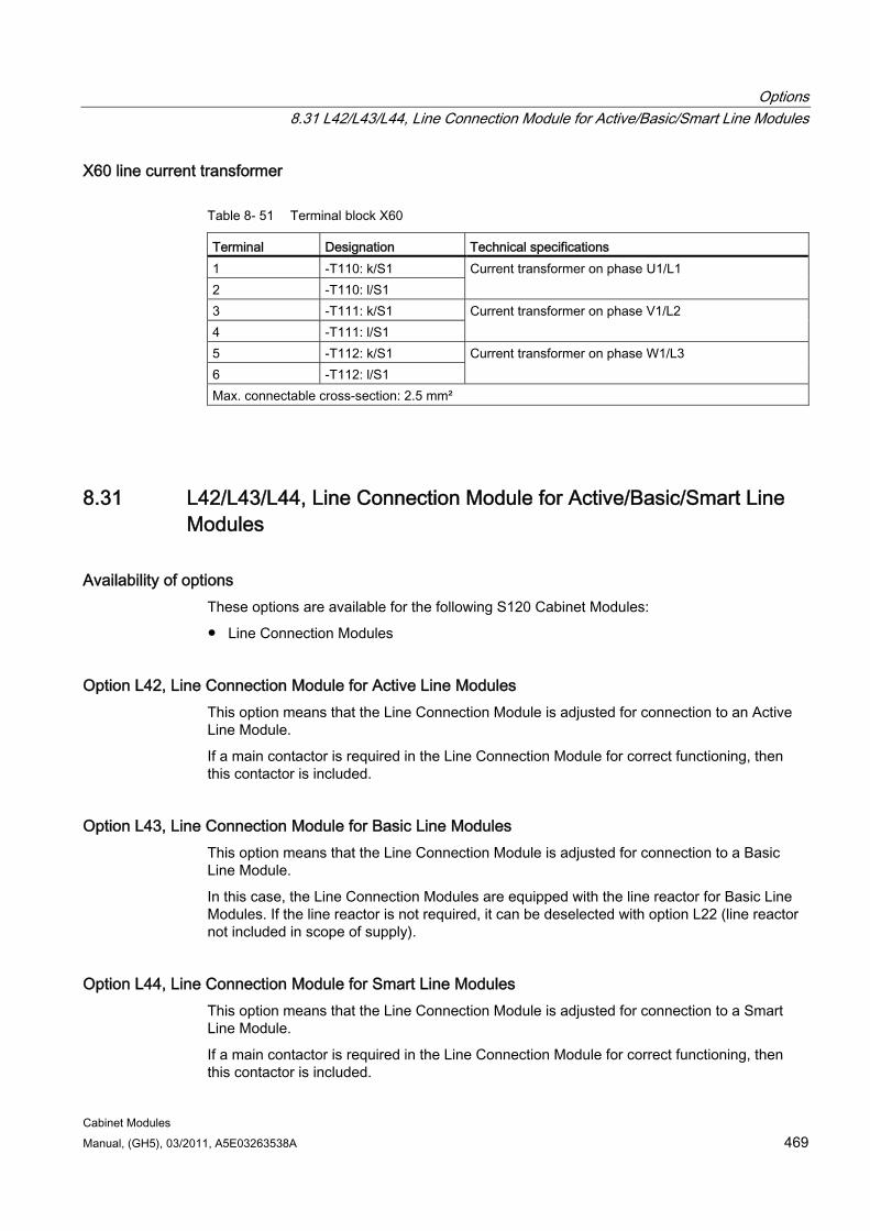
Options 8.31 L42/L43/L44, Line Connection Module for Active/Basic/Smart Line Modules
Cabinet Modules Manual, (GH5), 03/2011, A5E03263538A 469
X60 line current transformer
Table 8- 51 Terminal block X60
Terminal Designation Technical specifications 1 -T110: k/S1 2 -T110: l/S1
Current transformer on phase U1/L1
3 -T111: k/S1 4 -T111: l/S1
Current transformer on phase V1/L2
5 -T112: k/S1 6 -T112: l/S1
Current transformer on phase W1/L3
Max. connectable cross-section: 2.5 mm²
8.31 L42/L43/L44, Line Connection Module for Active/Basic/Smart Line Modules
Availability of options These options are available for the following S120 Cabinet Modules:
Line Connection Modules
Option L42, Line Connection Module for Active Line Modules This option means that the Line Connection Module is adjusted for connection to an Active Line Module.
If a main contactor is required in the Line Connection Module for correct functioning, then this contactor is included.
Option L43, Line Connection Module for Basic Line Modules This option means that the Line Connection Module is adjusted for connection to a Basic Line Module.
In this case, the Line Connection Modules are equipped with the line reactor for Basic Line Modules. If the line reactor is not required, it can be deselected with option L22 (line reactor not included in scope of supply).
Option L44, Line Connection Module for Smart Line Modules This option means that the Line Connection Module is adjusted for connection to a Smart Line Module.
If a main contactor is required in the Line Connection Module for correct functioning, then this contactor is included.
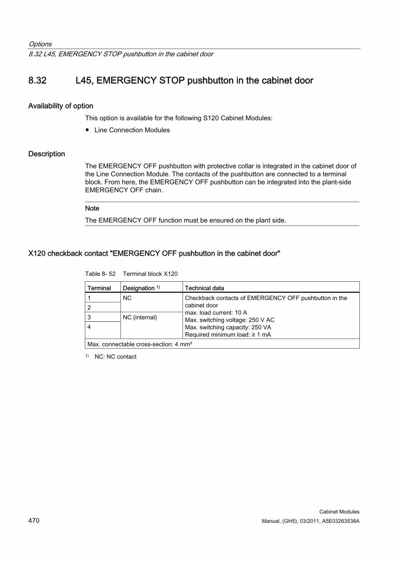
Options 8.32 L45, EMERGENCY STOP pushbutton in the cabinet door
Cabinet Modules 470 Manual, (GH5), 03/2011, A5E03263538A
8.32 L45, EMERGENCY STOP pushbutton in the cabinet door
Availability of option This option is available for the following S120 Cabinet Modules:
Line Connection Modules
Description The EMERGENCY OFF pushbutton with protective collar is integrated in the cabinet door of the Line Connection Module. The contacts of the pushbutton are connected to a terminal block. From here, the EMERGENCY OFF pushbutton can be integrated into the plant-side EMERGENCY OFF chain.
Note
The EMERGENCY OFF function must be ensured on the plant side.
X120 checkback contact "EMERGENCY OFF pushbutton in the cabinet door"
Table 8- 52 Terminal block X120
Terminal Designation 1) Technical data 1 2
NC
3 4
NC (internal)
Checkback contacts of EMERGENCY OFF pushbutton in the cabinet door max. load current: 10 A Max. switching voltage: 250 V AC Max. switching capacity: 250 VA Required minimum load: ≥ 1 mA
Max. connectable cross-section: 4 mm²
1) NC: NC contact
Options 8.33 L46/L47, grounding switch upstream/downstream of main breaker
Cabinet Modules Manual, (GH5), 03/2011, A5E03263538A 471
8.33 L46/L47, grounding switch upstream/downstream of main breaker
Availability of option This option is available for the following S120 Cabinet Modules:
Line Connection Modules (frame sizes KL and LL)
Description The grounding switch short-circuits the incoming supply line to ground for servicing. It is engaged manually by means of a rotary actuator and ensures, for example, safe isolation from supply in the Cabinet Module during servicing.
Two versions are available and can be supplied at the same time. Version 1 establishes a ground connection for the connected power lines, and Version 2 grounds the cabinet's internal components located downstream of the circuit breaker.
8.33.1 Grounding switch upstream of main breaker (option L46) The grounding switch upstream of the internal main breaker shorts the supply network to ground.
DANGER Plant-side measures must be taken to prevent the grounding switch from engaging when the voltage is applied. For this purpose, the checkback signal "Interruption of higher-level switches" must be connected to the higher-level switching equipment and must trigger immediate opening of the upstream main breaker, if necessary.
When the grounding switch is engaged, it must not be possible to switch in the power supply.
Note
The signals required for interlocking are available on the terminal block.
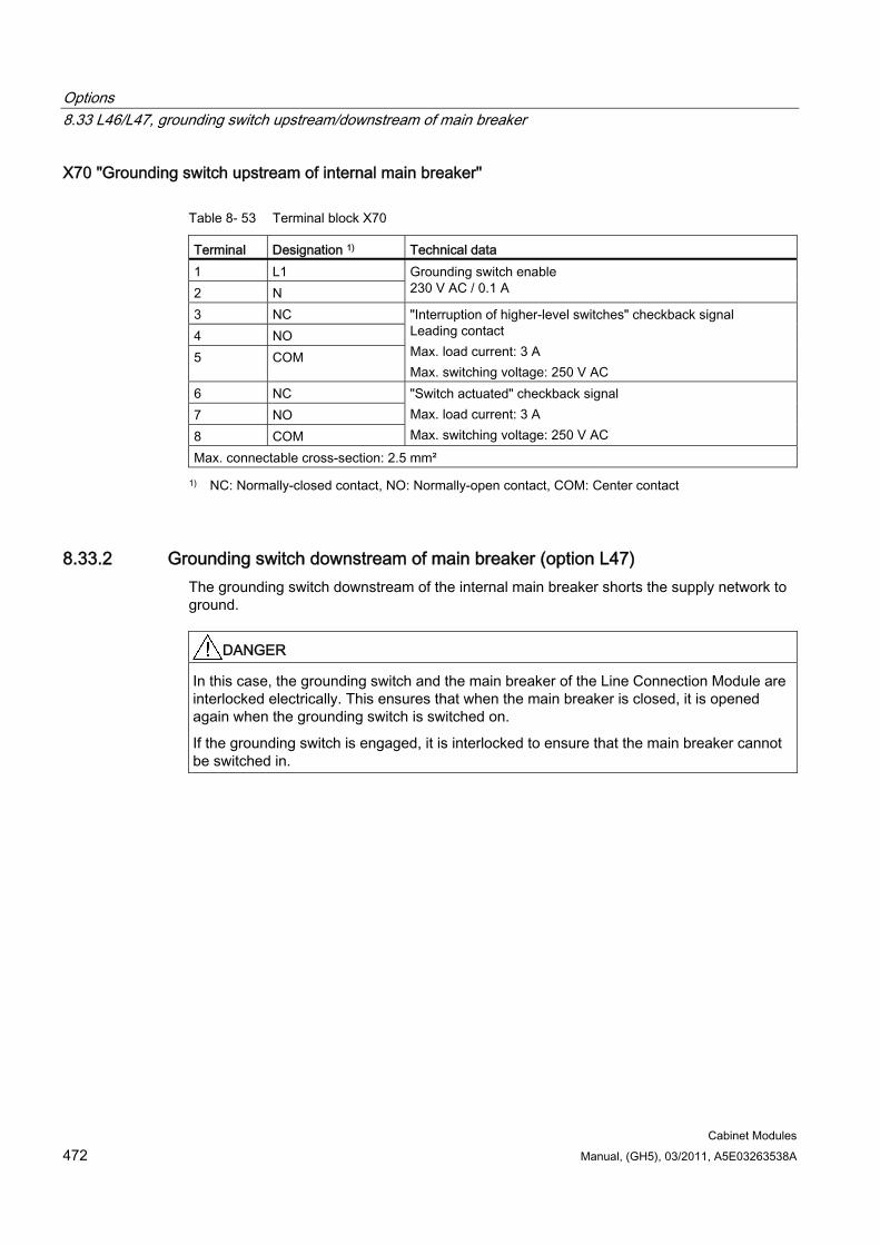
Options 8.33 L46/L47, grounding switch upstream/downstream of main breaker
Cabinet Modules 472 Manual, (GH5), 03/2011, A5E03263538A
X70 "Grounding switch upstream of internal main breaker"
Table 8- 53 Terminal block X70
Terminal Designation 1) Technical data 1 L1 2 N
Grounding switch enable 230 V AC / 0.1 A
3 NC 4 NO 5 COM
"Interruption of higher-level switches" checkback signal Leading contact Max. load current: 3 A Max. switching voltage: 250 V AC
6 NC 7 NO 8 COM
"Switch actuated" checkback signal Max. load current: 3 A Max. switching voltage: 250 V AC
Max. connectable cross-section: 2.5 mm²
1) NC: Normally-closed contact, NO: Normally-open contact, COM: Center contact
8.33.2 Grounding switch downstream of main breaker (option L47) The grounding switch downstream of the internal main breaker shorts the supply network to ground.
DANGER In this case, the grounding switch and the main breaker of the Line Connection Module are interlocked electrically. This ensures that when the main breaker is closed, it is opened again when the grounding switch is switched on.
If the grounding switch is engaged, it is interlocked to ensure that the main breaker cannot be switched in.
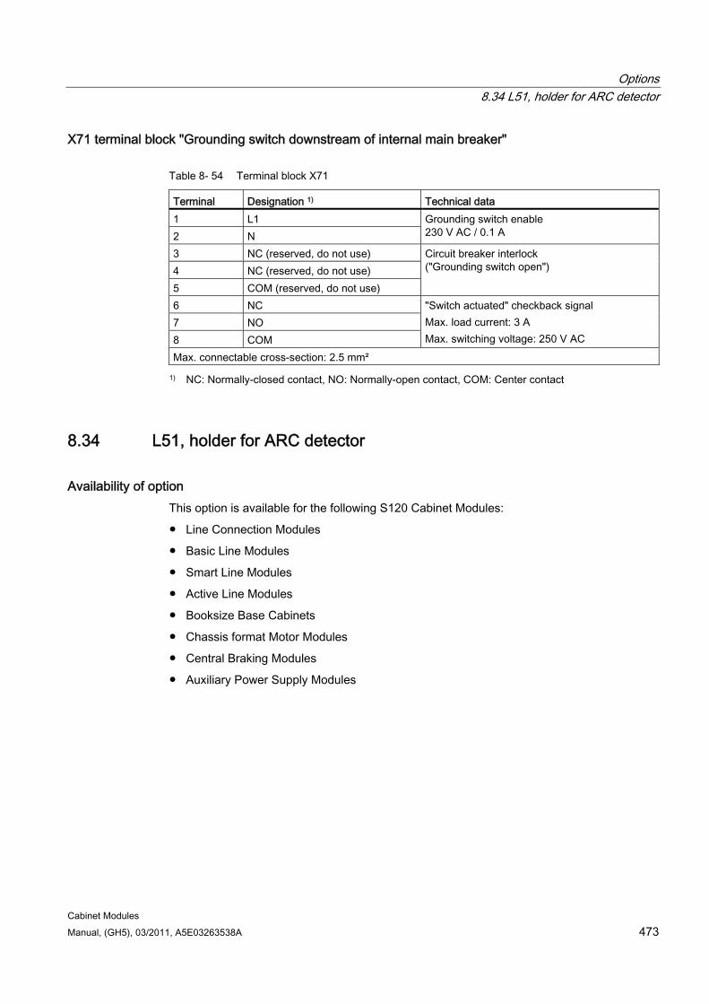
Options 8.34 L51, holder for ARC detector
Cabinet Modules Manual, (GH5), 03/2011, A5E03263538A 473
X71 terminal block "Grounding switch downstream of internal main breaker"
Table 8- 54 Terminal block X71
Terminal Designation 1) Technical data 1 L1 2 N
Grounding switch enable 230 V AC / 0.1 A
3 NC (reserved, do not use) 4 NC (reserved, do not use) 5 COM (reserved, do not use)
Circuit breaker interlock ("Grounding switch open")
6 NC 7 NO 8 COM
"Switch actuated" checkback signal Max. load current: 3 A Max. switching voltage: 250 V AC
Max. connectable cross-section: 2.5 mm²
1) NC: Normally-closed contact, NO: Normally-open contact, COM: Center contact
8.34 L51, holder for ARC detector
Availability of option This option is available for the following S120 Cabinet Modules:
Line Connection Modules
Basic Line Modules
Smart Line Modules
Active Line Modules
Booksize Base Cabinets
Chassis format Motor Modules
Central Braking Modules
Auxiliary Power Supply Modules
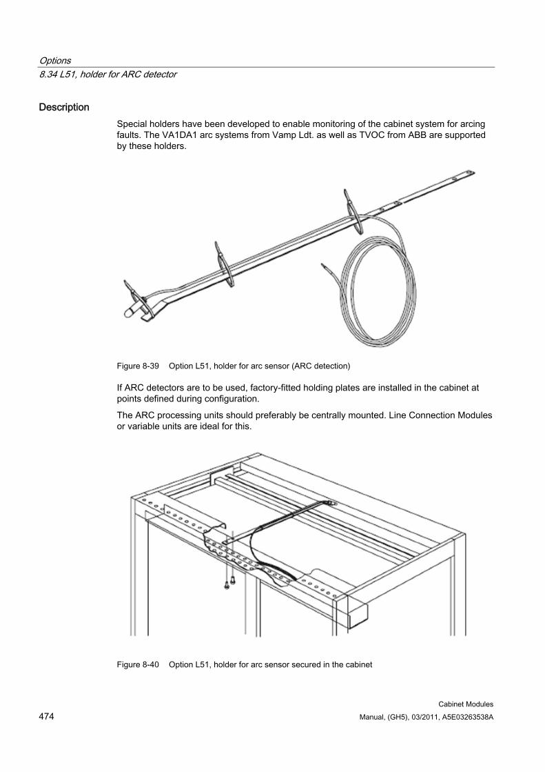
Options 8.34 L51, holder for ARC detector
Cabinet Modules 474 Manual, (GH5), 03/2011, A5E03263538A
Description Special holders have been developed to enable monitoring of the cabinet system for arcing faults. The VA1DA1 arc systems from Vamp Ldt. as well as TVOC from ABB are supported by these holders.
Figure 8-39 Option L51, holder for arc sensor (ARC detection)
If ARC detectors are to be used, factory-fitted holding plates are installed in the cabinet at points defined during configuration.
The ARC processing units should preferably be centrally mounted. Line Connection Modules or variable units are ideal for this.
Figure 8-40 Option L51, holder for arc sensor secured in the cabinet
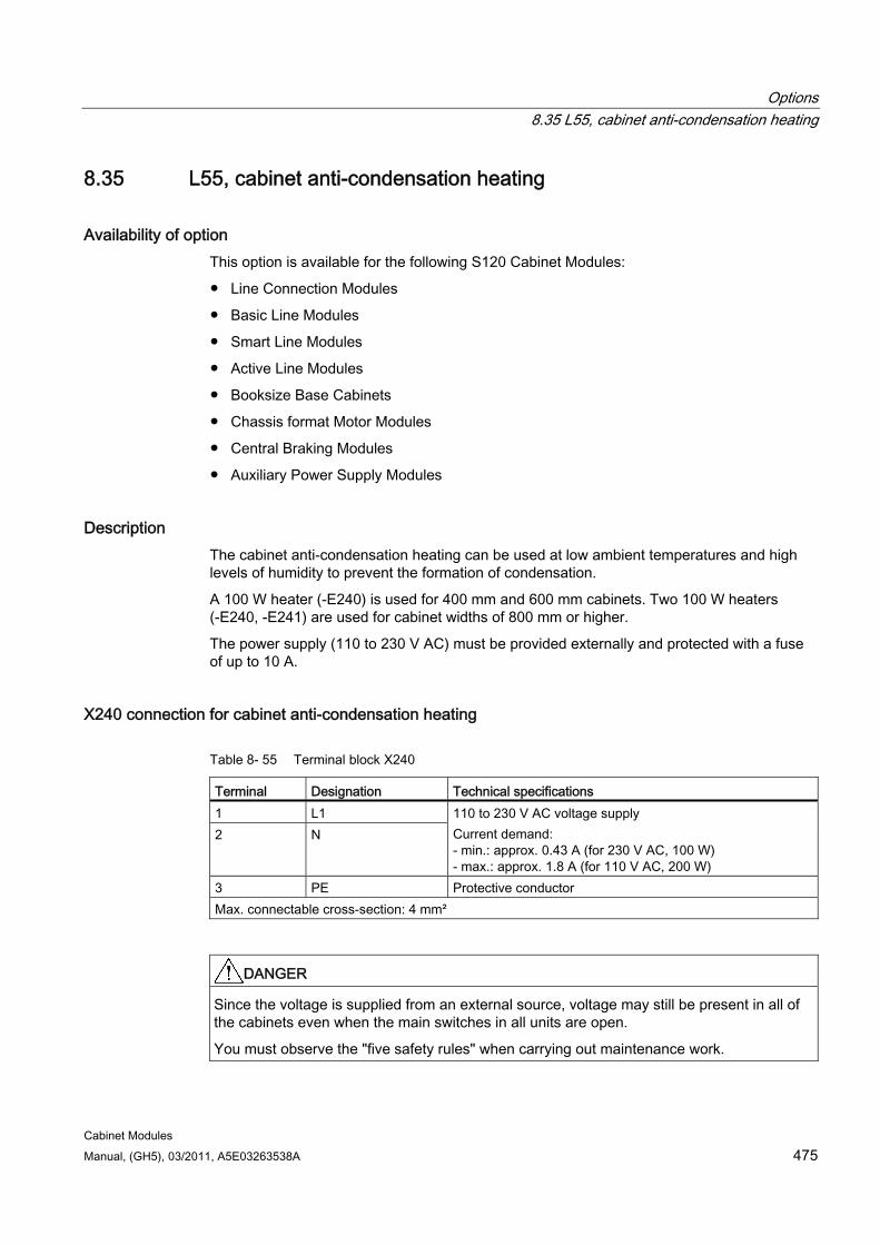
Options 8.35 L55, cabinet anti-condensation heating
Cabinet Modules Manual, (GH5), 03/2011, A5E03263538A 475
8.35 L55, cabinet anti-condensation heating
Availability of option This option is available for the following S120 Cabinet Modules:
Line Connection Modules
Basic Line Modules
Smart Line Modules
Active Line Modules
Booksize Base Cabinets
Chassis format Motor Modules
Central Braking Modules
Auxiliary Power Supply Modules
Description The cabinet anti-condensation heating can be used at low ambient temperatures and high levels of humidity to prevent the formation of condensation.
A 100 W heater (-E240) is used for 400 mm and 600 mm cabinets. Two 100 W heaters (-E240, -E241) are used for cabinet widths of 800 mm or higher.
The power supply (110 to 230 V AC) must be provided externally and protected with a fuse of up to 10 A.
X240 connection for cabinet anti-condensation heating
Table 8- 55 Terminal block X240
Terminal Designation Technical specifications 1 L1 2 N
110 to 230 V AC voltage supply Current demand: - min.: approx. 0.43 A (for 230 V AC, 100 W) - max.: approx. 1.8 A (for 110 V AC, 200 W)
3 PE Protective conductor Max. connectable cross-section: 4 mm²
DANGER Since the voltage is supplied from an external source, voltage may still be present in all of the cabinets even when the main switches in all units are open.
You must observe the "five safety rules" when carrying out maintenance work.
Options 8.36 L61/L62, L64/L65, braking units
Cabinet Modules 476 Manual, (GH5), 03/2011, A5E03263538A
8.36 L61/L62, L64/L65, braking units
8.36.1 General information
Availability of option This option is available for the following S120 Cabinet Modules:
Basic Line Modules
Smart Line Modules
Active Line Modules
Chassis format Motor Modules
Description Braking units may be required for drives that support regenerative operating conditions but have no other facility for feeding energy back into the supply system.
The braking unit comprises two components:
A Braking Module that is installed in the Power Module
A braking resistor to be mounted externally (degree of protection IP20)
The braking unit functions as an autonomous unit, and does not require an external power supply.
The Braking Modules are installed in the air outlet channel of the Basic Line Module, Smart Line Module, Active Line Module, or Motor Module.
During the braking process, the kinetic energy is converted into heat in the externally mounted braking resistor.
A maximum cable length of 100 mm is permissible between the Braking Module and the braking resistor. This allows the braking resistor to be mounted externally so that heat losses can be released outside the converter enclosure. The braking resistor is connected directly to the Braking Module terminals.
The application threshold of the Braking Module can be adjusted to the plant-side requirements using a threshold switch.
Note
Higher braking powers are available on request.
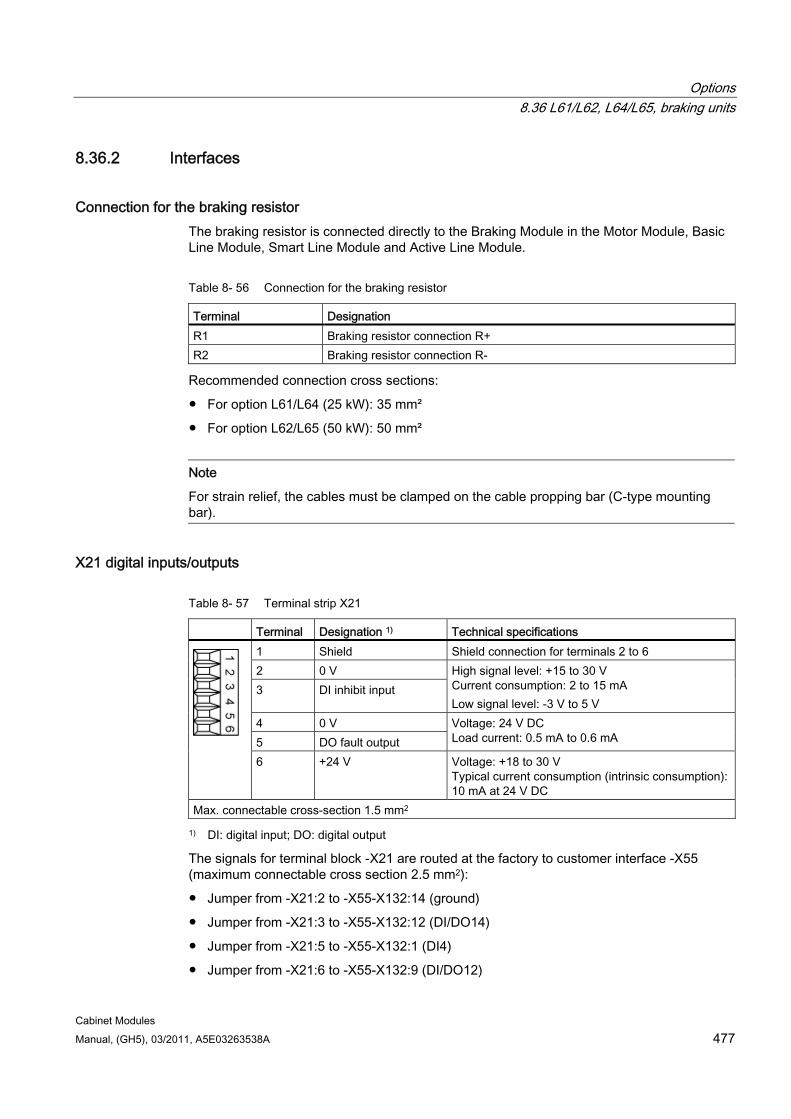
Options 8.36 L61/L62, L64/L65, braking units
Cabinet Modules Manual, (GH5), 03/2011, A5E03263538A 477
8.36.2 Interfaces
Connection for the braking resistor The braking resistor is connected directly to the Braking Module in the Motor Module, Basic Line Module, Smart Line Module and Active Line Module.
Table 8- 56 Connection for the braking resistor
Terminal Designation R1 Braking resistor connection R+ R2 Braking resistor connection R-
Recommended connection cross sections:
For option L61/L64 (25 kW): 35 mm²
For option L62/L65 (50 kW): 50 mm²
Note
For strain relief, the cables must be clamped on the cable propping bar (C-type mounting bar).
X21 digital inputs/outputs
Table 8- 57 Terminal strip X21
Terminal Designation 1) Technical specifications 1 Shield Shield connection for terminals 2 to 6 2 0 V 3 DI inhibit input
High signal level: +15 to 30 V Current consumption: 2 to 15 mA Low signal level: -3 V to 5 V
4 0 V 5 DO fault output
Voltage: 24 V DC Load current: 0.5 mA to 0.6 mA
6 +24 V Voltage: +18 to 30 V Typical current consumption (intrinsic consumption):10 mA at 24 V DC
Max. connectable cross-section 1.5 mm2
1) DI: digital input; DO: digital output
The signals for terminal block -X21 are routed at the factory to customer interface -X55 (maximum connectable cross section 2.5 mm2):
Jumper from -X21:2 to -X55-X132:14 (ground)
Jumper from -X21:3 to -X55-X132:12 (DI/DO14)
Jumper from -X21:5 to -X55-X132:1 (DI4)
Jumper from -X21:6 to -X55-X132:9 (DI/DO12)
Options 8.36 L61/L62, L64/L65, braking units
Cabinet Modules 478 Manual, (GH5), 03/2011, A5E03263538A
Note
Applying a high signal level to "DI inhibit input" inhibits the Braking Module. On a falling edge, pending error messages are acknowledged.
The "DO fault output" signal can be used for evaluation in the Control Unit.
On the "+24 V" signal, 24 V DC must be provided by the customer to supply the Braking Module.
Commissioning/parameterization If a Control Unit is not being used (option K90/K95), then the four signals of terminal block -X55-X132 must be wired to the corresponding Control Unit or to the customer interface -X55.
8.36.3 S1 - Threshold switch The response threshold at which the Braking Module is activated and the DC link voltage generated during braking is specified in the following table.
WARNING The threshold switch position may be changed only when the Basic Line, Smart Line, Active Line, or Motor Module are switched off and the DC link capacitors are discharged.
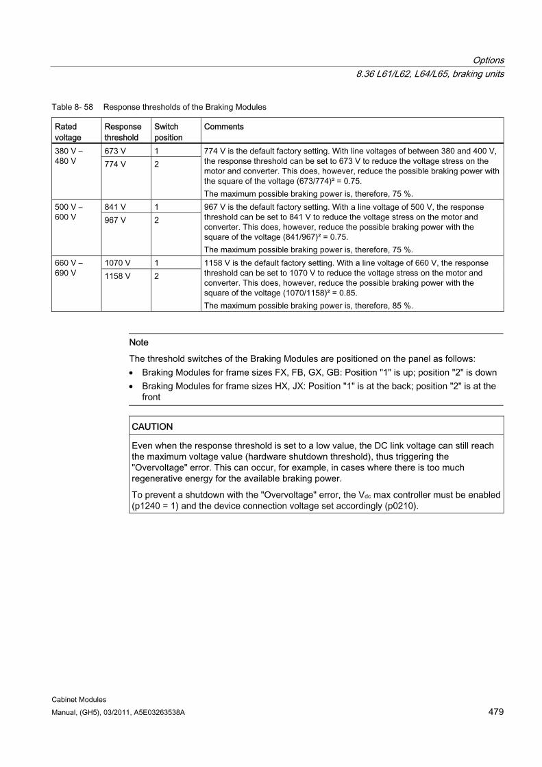
Options 8.36 L61/L62, L64/L65, braking units
Cabinet Modules Manual, (GH5), 03/2011, A5E03263538A 479
Table 8- 58 Response thresholds of the Braking Modules
Rated voltage
Response threshold
Switch position
Comments
673 V 1 380 V – 480 V 774 V 2
774 V is the default factory setting. With line voltages of between 380 and 400 V, the response threshold can be set to 673 V to reduce the voltage stress on the motor and converter. This does, however, reduce the possible braking power with the square of the voltage (673/774)² = 0.75. The maximum possible braking power is, therefore, 75 %.
841 V 1 500 V – 600 V 967 V 2
967 V is the default factory setting. With a line voltage of 500 V, the response threshold can be set to 841 V to reduce the voltage stress on the motor and converter. This does, however, reduce the possible braking power with the square of the voltage (841/967)² = 0.75. The maximum possible braking power is, therefore, 75 %.
1070 V 1 660 V – 690 V 1158 V 2
1158 V is the default factory setting. With a line voltage of 660 V, the response threshold can be set to 1070 V to reduce the voltage stress on the motor and converter. This does, however, reduce the possible braking power with the square of the voltage (1070/1158)² = 0.85. The maximum possible braking power is, therefore, 85 %.
Note
The threshold switches of the Braking Modules are positioned on the panel as follows: Braking Modules for frame sizes FX, FB, GX, GB: Position "1" is up; position "2" is down Braking Modules for frame sizes HX, JX: Position "1" is at the back; position "2" is at the
front
CAUTION Even when the response threshold is set to a low value, the DC link voltage can still reach the maximum voltage value (hardware shutdown threshold), thus triggering the "Overvoltage" error. This can occur, for example, in cases where there is too much regenerative energy for the available braking power.
To prevent a shutdown with the "Overvoltage" error, the Vdc max controller must be enabled (p1240 = 1) and the device connection voltage set accordingly (p0210).
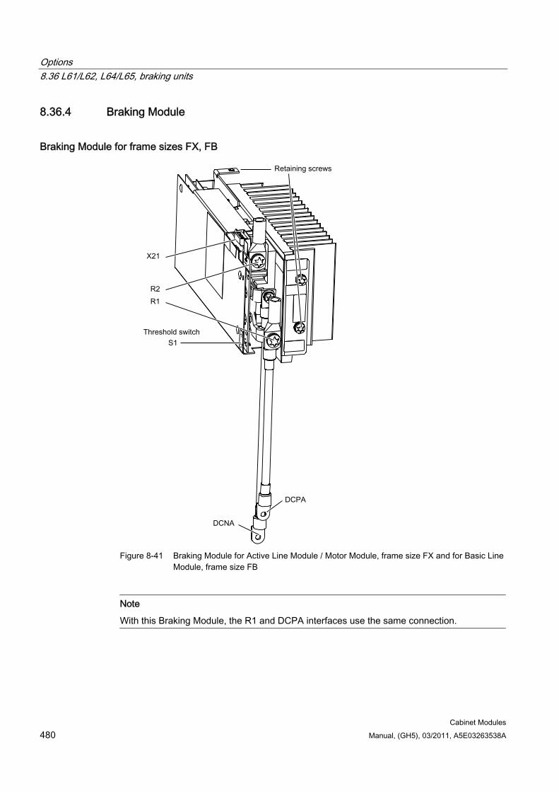
Options 8.36 L61/L62, L64/L65, braking units
Cabinet Modules 480 Manual, (GH5), 03/2011, A5E03263538A
8.36.4 Braking Module
Braking Module for frame sizes FX, FB
Figure 8-41 Braking Module for Active Line Module / Motor Module, frame size FX and for Basic Line
Module, frame size FB
Note
With this Braking Module, the R1 and DCPA interfaces use the same connection.
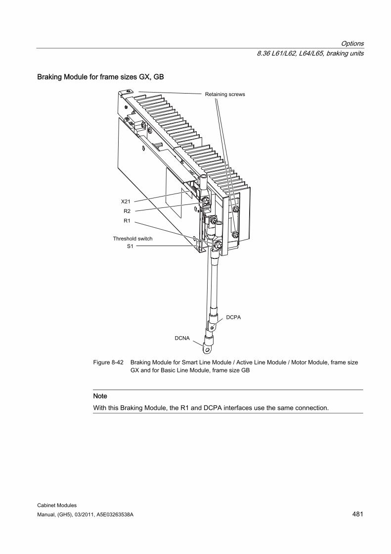
Options 8.36 L61/L62, L64/L65, braking units
Cabinet Modules Manual, (GH5), 03/2011, A5E03263538A 481
Braking Module for frame sizes GX, GB
Figure 8-42 Braking Module for Smart Line Module / Active Line Module / Motor Module, frame size
GX and for Basic Line Module, frame size GB
Note
With this Braking Module, the R1 and DCPA interfaces use the same connection.
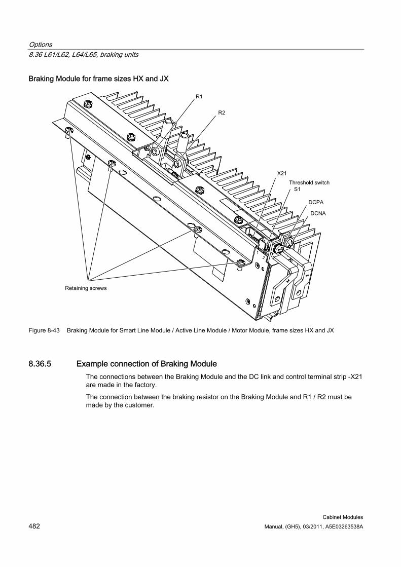
Options 8.36 L61/L62, L64/L65, braking units
Cabinet Modules 482 Manual, (GH5), 03/2011, A5E03263538A
Braking Module for frame sizes HX and JX
Figure 8-43 Braking Module for Smart Line Module / Active Line Module / Motor Module, frame sizes HX and JX
8.36.5 Example connection of Braking Module The connections between the Braking Module and the DC link and control terminal strip -X21 are made in the factory.
The connection between the braking resistor on the Braking Module and R1 / R2 must be made by the customer.
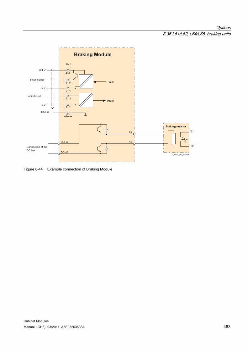
Options 8.36 L61/L62, L64/L65, braking units
Cabinet Modules Manual, (GH5), 03/2011, A5E03263538A 483
Braking resistor
Shield
Inhibit input
Fault output
Inhibit
DC linkConnection at the
Fault
Braking Module
21.6
21.5
21.4
21.3
21.2
21.1
X21
+24 V
0 V
0 V
R1
DCNA
R2DCPA
T1
T2
G_D211_DE_00012a
Figure 8-44 Example connection of Braking Module
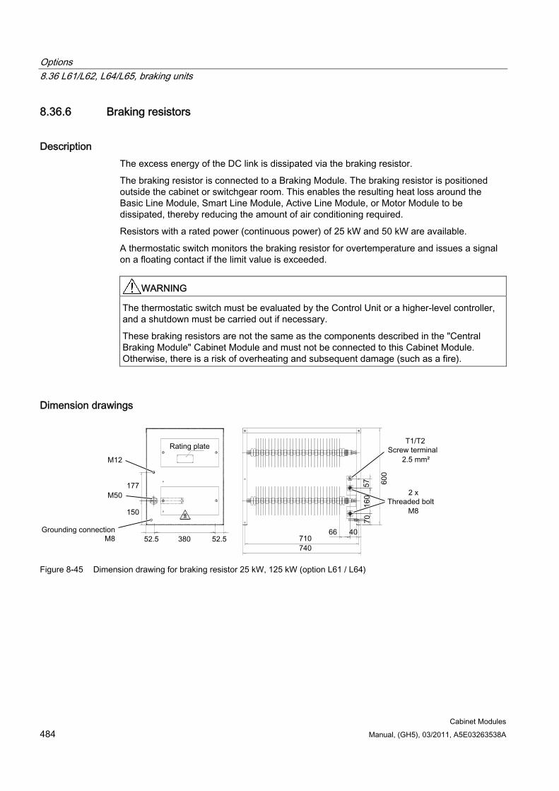
Options 8.36 L61/L62, L64/L65, braking units
Cabinet Modules 484 Manual, (GH5), 03/2011, A5E03263538A
8.36.6 Braking resistors
Description The excess energy of the DC link is dissipated via the braking resistor.
The braking resistor is connected to a Braking Module. The braking resistor is positioned outside the cabinet or switchgear room. This enables the resulting heat loss around the Basic Line Module, Smart Line Module, Active Line Module, or Motor Module to be dissipated, thereby reducing the amount of air conditioning required.
Resistors with a rated power (continuous power) of 25 kW and 50 kW are available.
A thermostatic switch monitors the braking resistor for overtemperature and issues a signal on a floating contact if the limit value is exceeded.
WARNING The thermostatic switch must be evaluated by the Control Unit or a higher-level controller, and a shutdown must be carried out if necessary.
These braking resistors are not the same as the components described in the "Central Braking Module" Cabinet Module and must not be connected to this Cabinet Module. Otherwise, there is a risk of overheating and subsequent damage (such as a fire).
Dimension drawings
Figure 8-45 Dimension drawing for braking resistor 25 kW, 125 kW (option L61 / L64)
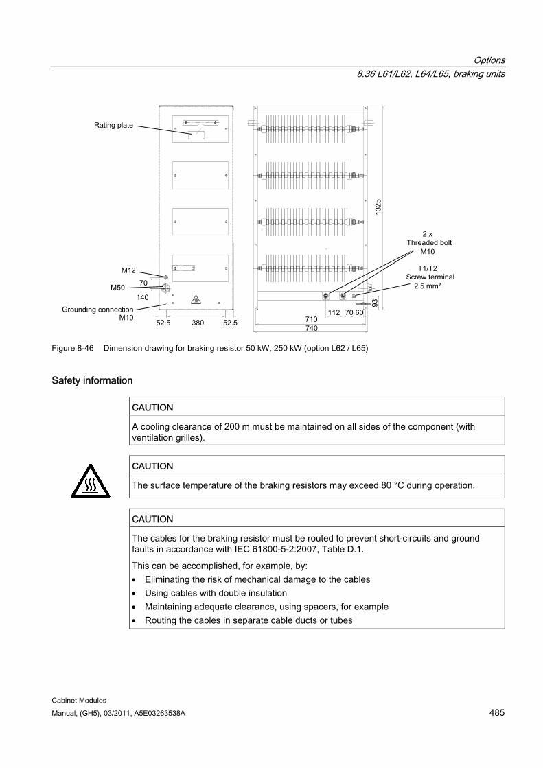
Options 8.36 L61/L62, L64/L65, braking units
Cabinet Modules Manual, (GH5), 03/2011, A5E03263538A 485
Figure 8-46 Dimension drawing for braking resistor 50 kW, 250 kW (option L62 / L65)
Safety information
CAUTION A cooling clearance of 200 m must be maintained on all sides of the component (with ventilation grilles).
CAUTION
The surface temperature of the braking resistors may exceed 80 °C during operation.
CAUTION The cables for the braking resistor must be routed to prevent short-circuits and ground faults in accordance with IEC 61800-5-2:2007, Table D.1.
This can be accomplished, for example, by: Eliminating the risk of mechanical damage to the cables Using cables with double insulation Maintaining adequate clearance, using spacers, for example Routing the cables in separate cable ducts or tubes
Options 8.36 L61/L62, L64/L65, braking units
Cabinet Modules 486 Manual, (GH5), 03/2011, A5E03263538A
Note
The connecting cables to the Braking Module in the Basic Line Module, Smart Line Module, Active Line Module, or Motor Module must be kept as short as possible (maximum of 100 m).
The braking resistors are only suitable for floor mounting.
The maximum cable length between the cabinet unit and braking resistor is 100 m.
Sufficient space must be available for dissipating the energy converted by the braking resistor.
A sufficient distance from flammable objects must be ensured.
The braking resistor must be installed as a free-standing unit.
Objects must not be placed on or anywhere above the braking resistor.
The braking resistor should not be installed underneath fire-detection systems, since these could be triggered by the resulting heat.
For outdoor installation, a hood should be provided to protect the braking resistor against precipitation (in accordance with degree of protection IP20).
Connecting the braking resistor
WARNING The Braking Module must only be connected when the Basic Line Module, Smart Line Module, Active Line Module, or Motor Module has been disconnected from the power supply and the DC link has been discharged.
CAUTION The cables for the braking resistor must be routed to prevent short-circuits and ground faults in accordance with IEC 61800-5-2:2007, Table D.1.
This can be accomplished, for example, by: Eliminating the risk of mechanical damage to the cables Using cables with double insulation Maintaining adequate clearance, using spacers, for example Routing the cables in separate cable ducts or tubes
Note
The length of the connecting cables between the Braking Module and external braking resistor must not exceed 100 m.

Options 8.36 L61/L62, L64/L65, braking units
Cabinet Modules Manual, (GH5), 03/2011, A5E03263538A 487
Braking resistor connection The connection between the braking resistor on the Braking Module and R1 / R2 must be made by the customer.
Table 8- 59 Connection for external braking resistor
Terminal Function R1 Braking resistor connection R2 Braking resistor connection Max. connectable cross-section: 50 mm²
Recommended connection cross sections:
For option L61/L64 (25 kW): 35 mm²
For option L62/L65 (50 kW): 50 mm²
To relieve the strain on the cables from the Braking Module to the external braking resistor, they must be propped on the cable propping bar (C-type mounting bar) above the Braking Modules.
Thermostatic switch
Table 8- 60 Thermostatic switch connection
Terminal Function T1 Thermostatic switch connection T2 Thermostatic switch connection Max. connectable cross-section: 1.5 mm²
WARNING The thermostatic switch must be evaluated by the Control Unit or a higher-level controller, and a shutdown must be carried out if necessary.
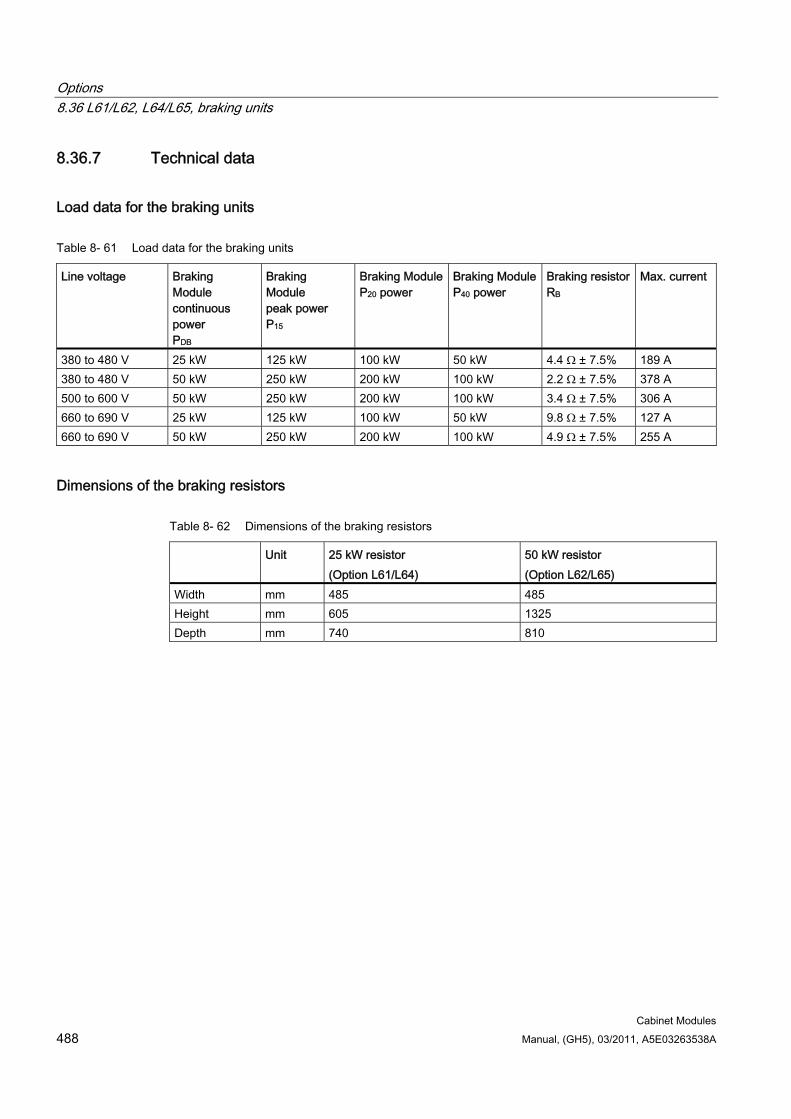
Options 8.36 L61/L62, L64/L65, braking units
Cabinet Modules 488 Manual, (GH5), 03/2011, A5E03263538A
8.36.7 Technical data
Load data for the braking units
Table 8- 61 Load data for the braking units
Line voltage Braking Module continuous power PDB
Braking Module peak power P15
Braking Module P20 power
Braking Module P40 power
Braking resistor RB
Max. current
380 to 480 V 25 kW 125 kW 100 kW 50 kW 4.4 Ω ± 7.5% 189 A 380 to 480 V 50 kW 250 kW 200 kW 100 kW 2.2 Ω ± 7.5% 378 A 500 to 600 V 50 kW 250 kW 200 kW 100 kW 3.4 Ω ± 7.5% 306 A 660 to 690 V 25 kW 125 kW 100 kW 50 kW 9.8 Ω ± 7.5% 127 A 660 to 690 V 50 kW 250 kW 200 kW 100 kW 4.9 Ω ± 7.5% 255 A
Dimensions of the braking resistors
Table 8- 62 Dimensions of the braking resistors
Unit 25 kW resistor (Option L61/L64)
50 kW resistor (Option L62/L65)
Width mm 485 485 Height mm 605 1325 Depth mm 740 810
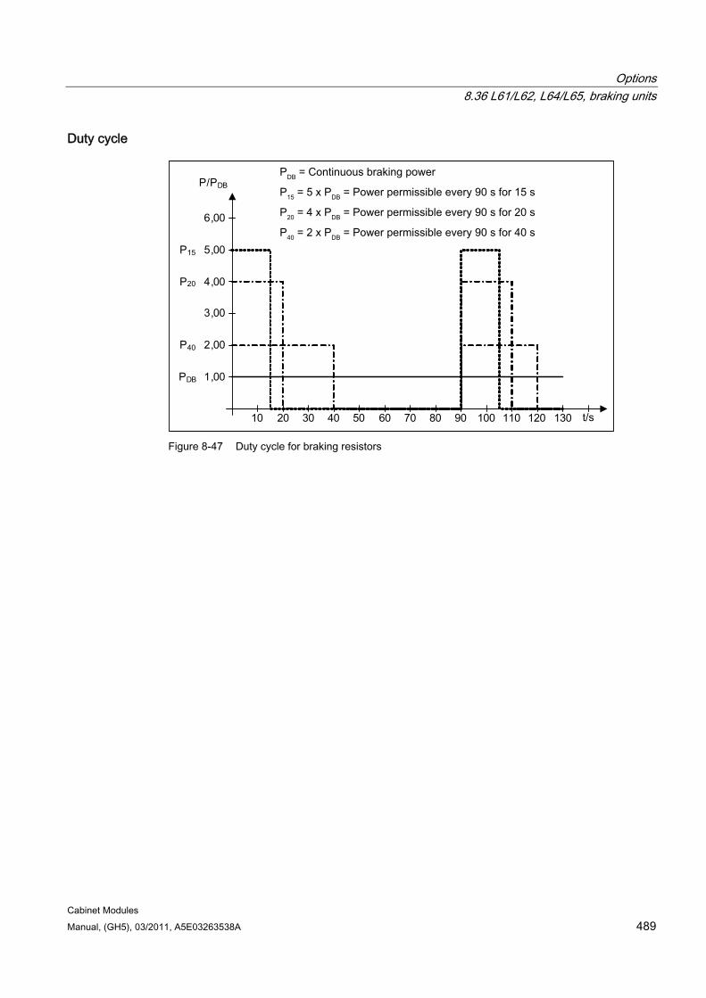
Options 8.36 L61/L62, L64/L65, braking units
Cabinet Modules Manual, (GH5), 03/2011, A5E03263538A 489
Duty cycle
PDB = Continuous braking power
t/s
P15 = 5 x PDB = Power permissible every 90 s for 15 s
P40 = 2 x PDB = Power permissible every 90 s for 40 s
P20 = 4 x PDB = Power permissible every 90 s for 20 s
10 20 30 40 50 60 70 80 90 100 110 120 130
1,00
2,00
3,00
4,00
5,00
6,00
P/PDB
P15
P20
P40
PDB
Figure 8-47 Duty cycle for braking resistors
Options 8.37 L87, insulation monitoring
Cabinet Modules 490 Manual, (GH5), 03/2011, A5E03263538A
8.37 L87, insulation monitoring
Availability of option This option is available for the following S120 Cabinet Modules:
Line Connection Modules
Description In non-grounded systems (IT systems), the insulation monitor checks the entire electrically-connected circuit for insulation faults. It measures the insulation resistance as well as all insulation faults in the Cabinet Modules, from the supply infeed to the motors. Two response values (between 1 kΩ and 10 MΩ) can be set. If a response value is undershot, a warning is output to the terminal. System errors are output via the signaling-relay system.
When the Cabinet Module is delivered, the plant configuration (one or several loads in one electrically-connected network) and the protection philosophy (immediate shutdown in the event of an insulation fault or restricted continued motion) can vary. This means that the signaling relays of the insulation monitor must be integrated by the customer in the fault and warning sequence.
Safety information
NOTICE Only one insulation monitor can be used within the same electrically-connected network.
Note
When using the insulation monitor, you must remove the connection clamp for the noise suppression capacitor (in the Active Interface Module of the Active Line Module, Basic Line Module, or Smart Line Module).
See the chapter titled "Connections: Connecting Cabinet Modules to non-grounded line supplies (IT systems)"
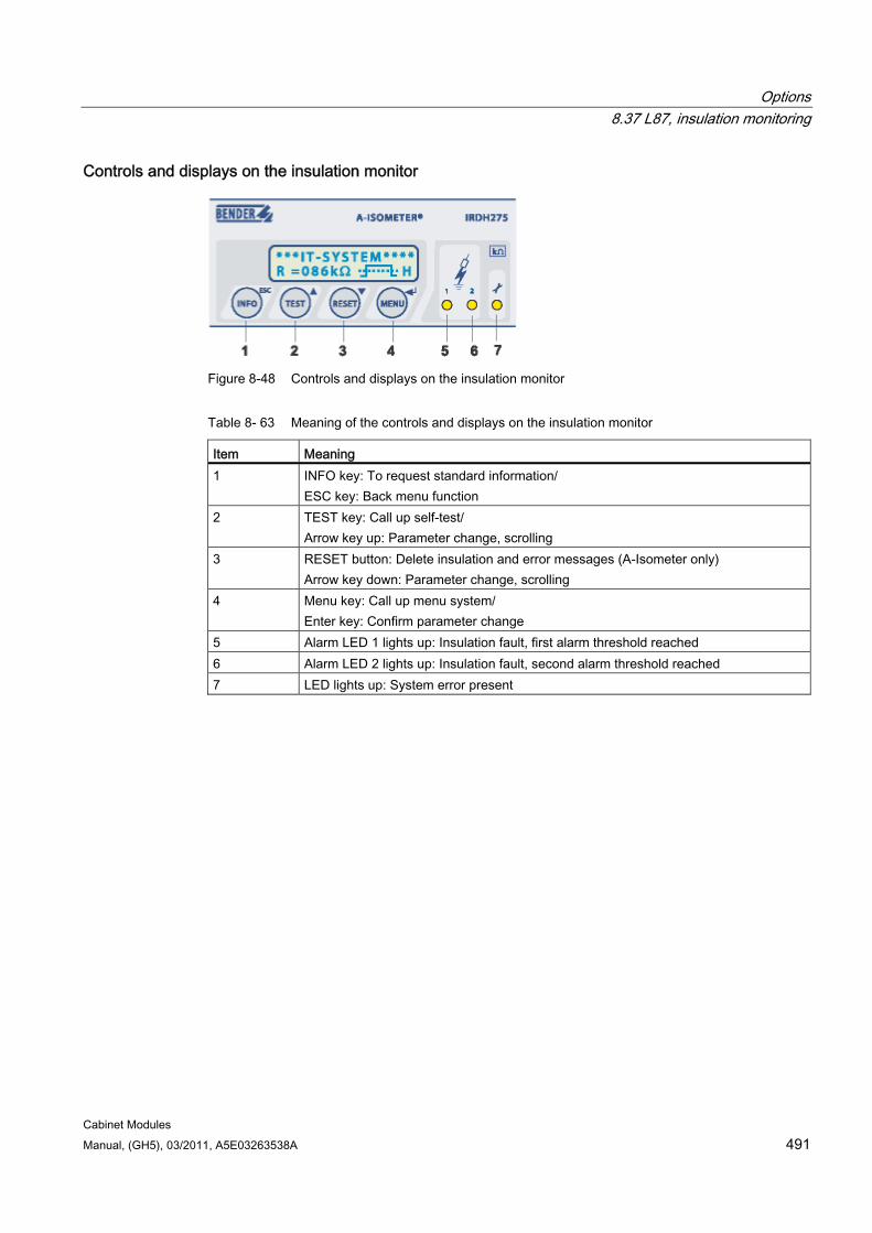
Options 8.37 L87, insulation monitoring
Cabinet Modules Manual, (GH5), 03/2011, A5E03263538A 491
Controls and displays on the insulation monitor
Figure 8-48 Controls and displays on the insulation monitor
Table 8- 63 Meaning of the controls and displays on the insulation monitor
Item Meaning 1 INFO key: To request standard information/
ESC key: Back menu function 2 TEST key: Call up self-test/
Arrow key up: Parameter change, scrolling 3 RESET button: Delete insulation and error messages (A-Isometer only)
Arrow key down: Parameter change, scrolling 4 Menu key: Call up menu system/
Enter key: Confirm parameter change 5 Alarm LED 1 lights up: Insulation fault, first alarm threshold reached 6 Alarm LED 2 lights up: Insulation fault, second alarm threshold reached 7 LED lights up: System error present
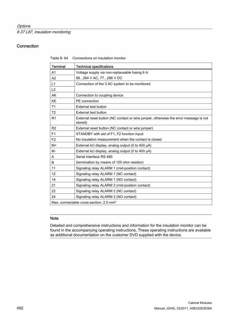
Options 8.37 L87, insulation monitoring
Cabinet Modules 492 Manual, (GH5), 03/2011, A5E03263538A
Connection
Table 8- 64 Connections on insulation monitor
Terminal Technical specifications A1 A2
Voltage supply via non-replaceable fusing 6 A: 88...264 V AC, 77...286 V DC
L1 L2
Connection of the 3 AC system to be monitored
AK Connection to coupling device KE PE connection T1 External test button T2 External test button R1 External reset button (NC contact or wire jumper, otherwise the error message is not
stored) R2 External reset button (NC contact or wire jumper) F1 F2
STANDBY with aid of F1, F2 function input: No insulation measurement when the contact is closed
M+ External kΩ display, analog output (0 to 400 μA) M- External kΩ display, analog output (0 to 400 μA) A B
Serial interface RS 485 (termination by means of 120 ohm resistor)
11 Signaling relay ALARM 1 (mid-position contact) 12 Signaling relay ALARM 1 (NC contact) 14 Signaling relay ALARM 1 (NO contact) 21 Signaling relay ALARM 2 (mid-position contact) 22 Signaling relay ALARM 2 (NC contact) 24 Signaling relay ALARM 2 (NO contact) Max. connectable cross-section: 2.5 mm²
Note
Detailed and comprehensive instructions and information for the insulation monitor can be found in the accompanying operating instructions, These operating instructions are available as additional documentation on the customer DVD supplied with the device.
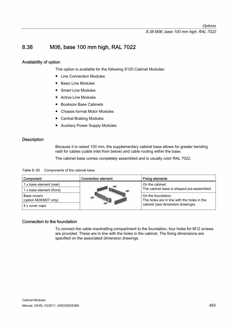
Options 8.38 M06, base 100 mm high, RAL 7022
Cabinet Modules Manual, (GH5), 03/2011, A5E03263538A 493
8.38 M06, base 100 mm high, RAL 7022
Availability of option This option is available for the following S120 Cabinet Modules:
Line Connection Modules
Basic Line Modules
Smart Line Modules
Active Line Modules
Booksize Base Cabinets
Chassis format Motor Modules
Central Braking Modules
Auxiliary Power Supply Modules
Description Because it is raised 100 mm, the supplementary cabinet base allows for greater bending radii for cables (cable inlet from below) and cable routing within the base.
The cabinet base comes completely assembled and is usually color RAL 7022.
Table 8- 65 Components of the cabinet base
Component Connection element Fixing elements 1 x base element (rear) 1 x base element (front)
On the cabinet: The cabinet base is shipped pre-assembled.
Base covers (option M26/M27 only) 4 x cover caps
On the foundation: The holes are in line with the holes in the cabinet (see dimension drawings).
Connection to the foundation To connect the cable marshalling compartment to the foundation, four holes for M12 screws are provided. These are in line with the holes in the cabinet. The fixing dimensions are specified on the associated dimension drawings.
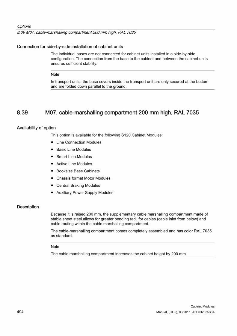
Options 8.39 M07, cable-marshalling compartment 200 mm high, RAL 7035
Cabinet Modules 494 Manual, (GH5), 03/2011, A5E03263538A
Connection for side-by-side installation of cabinet units The individual bases are not connected for cabinet units installed in a side-by-side configuration. The connection from the base to the cabinet and between the cabinet units ensures sufficient stability.
Note
In transport units, the base covers inside the transport unit are only secured at the bottom and are folded down parallel to the ground.
8.39 M07, cable-marshalling compartment 200 mm high, RAL 7035
Availability of option This option is available for the following S120 Cabinet Modules:
Line Connection Modules
Basic Line Modules
Smart Line Modules
Active Line Modules
Booksize Base Cabinets
Chassis format Motor Modules
Central Braking Modules
Auxiliary Power Supply Modules
Description Because it is raised 200 mm, the supplementary cable marshalling compartment made of stable sheet steel allows for greater bending radii for cables (cable inlet from below) and cable routing within the cable marshalling compartment.
The cable-marshalling compartment comes completely assembled and has color RAL 7035 as standard.
Note
The cable marshalling compartment increases the cabinet height by 200 mm.
Options 8.39 M07, cable-marshalling compartment 200 mm high, RAL 7035
Cabinet Modules Manual, (GH5), 03/2011, A5E03263538A 495
Table 8- 66 Components of the cable marshalling compartment
Component Connection element Fixing elements 1 x cable marshalling compartment element
On the cabinet: The cabinet's cable marshalling compartment is shipped pre-assembled. Side shutters
(not shown) for the cable marshalling compartment (option M26/M27 only)
On the foundation: The holes are in line with the holes in the cabinet (see dimension drawings).
Connection to the foundation To connect the cable marshalling compartment to the foundation, four holes for M12 screws are provided. These are in line with the holes in the cabinet. The fixing dimensions are specified on the associated dimension drawings.
Connection for side-by-side installation of cabinet units The individual cable marshalling compartments are not connected for cabinet units installed in a side-by-side configuration. The connection from the cable marshalling compartments to the cabinet and between the cabinet units ensures sufficient stability.
Side shutters for cable marshalling compartments When the cabinet units are installed in a side-by-side configuration, the side shutters can be folded inward and upward.
Options 8.40 M13, Line connection from above
Cabinet Modules 496 Manual, (GH5), 03/2011, A5E03263538A
8.40 M13, Line connection from above
Availability of option This option is available for the following S120 cabinet modules:
Line connection modules
Description For option M13 the cabinet unit is equipped with an additional hood. The connection lugs for the power cables, the clamping bar for mechanically securing the cables, an EMC shield bus, and a PE busbar are located within the hood.
The roof cover increases the cabinet height by 405 mm. The busbars for connection from above are already installed when the system is delivered. For transport reasons, the hoods are delivered separately and have to be assembled at the plant. With options M23, M43 and M54, plastic ventilation grilles and filter mats are also supplied.
A 5 mm aluminum mounting plate (with no holes) is fitted in the roof of the cover for feeding in the cables. Depending on the number of cables and the cross-sections used, holes for attaching cable glands for feeding in the cables must be drilled in this mounting plate on site.
Note
The control cable and optional brake resistors are always connected from below.
Attaching the hood 1. Remove the crane transport assemblies (if fitted).
2. Options M43 and M54 only: Use the sealing tape provided to attach the contact surfaces of the hood to the top of the cabinet.
3. Fit the hood to the top of the enclosure at the positions specified (fixing points for the crane transport assemblies).
4. To secure the power cables, remove the front panel of the hood.
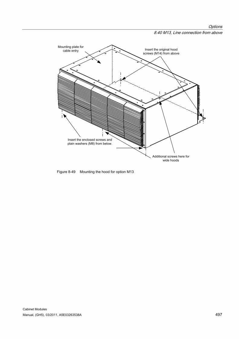
Options 8.40 M13, Line connection from above
Cabinet Modules Manual, (GH5), 03/2011, A5E03263538A 497
Figure 8-49 Mounting the hood for option M13
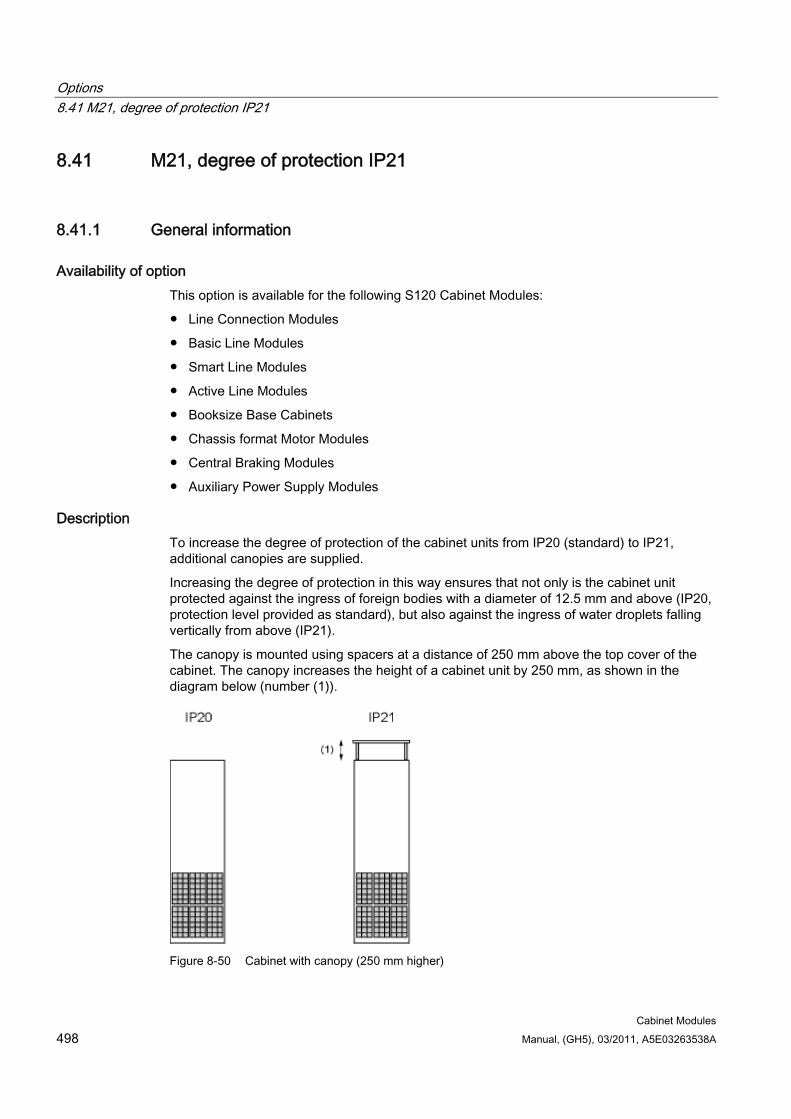
Options 8.41 M21, degree of protection IP21
Cabinet Modules 498 Manual, (GH5), 03/2011, A5E03263538A
8.41 M21, degree of protection IP21
8.41.1 General information
Availability of option This option is available for the following S120 Cabinet Modules:
Line Connection Modules
Basic Line Modules
Smart Line Modules
Active Line Modules
Booksize Base Cabinets
Chassis format Motor Modules
Central Braking Modules
Auxiliary Power Supply Modules
Description To increase the degree of protection of the cabinet units from IP20 (standard) to IP21, additional canopies are supplied.
Increasing the degree of protection in this way ensures that not only is the cabinet unit protected against the ingress of foreign bodies with a diameter of 12.5 mm and above (IP20, protection level provided as standard), but also against the ingress of water droplets falling vertically from above (IP21).
The canopy is mounted using spacers at a distance of 250 mm above the top cover of the cabinet. The canopy increases the height of a cabinet unit by 250 mm, as shown in the diagram below (number (1)).
Figure 8-50 Cabinet with canopy (250 mm higher)
Options 8.41 M21, degree of protection IP21
Cabinet Modules Manual, (GH5), 03/2011, A5E03263538A 499
NOTICE Only the protective requirements described above can be fulfilled with IP21. For more stringent requirements, you must select the corresponding IP degree of protection (for example, IP23 for additional protection against spraying water).
Note Installing the canopy or hood at a an early stage!
It is recommended to attach the canopy or hood at an early stage to prevent foreign matter entering the cabinet units.
8.41.2 Mounting
Mounting a canopy to increase the degree of protection to IP21 (option M21) The canopy ② can be mounted variably in both directions (on the side and, to the front or back) on the top of the cabinet. The arrangement can be adapted to the various installation conditions for the cabinets. This produces an adjustable protrusion of the canopy at the front ① and rear ③. In this way, it is possible to have a circumferential protrusion of the canopy, or direct contact with the wall or between the canopies in back-to-back installation. If necessary, seal the contact points in the case of wall-mounting or back-to-back installation.
Remove any existing crane transport assemblies.
Attach the spacers (A) to the roof of the cabinet at the positions specified. Under certain circumstances, it may be necessary to remove the protective grille for installation. Install the screws ④ with contact washer from below through the perforated protective grille (tightening torque: 13 Nm for M6).
Mount the canopy (B) on the spacers. Attach the screw ⑤ with contact washer from above through the canopy (tightening torque: 13 Nm for M6).
NOTICE In order to prevent water dripping into the spaces between the cabinet units connected in series, there are overlaps on the sides of the canopies. When fitting the canopies, make sure that the overlaps interlock.
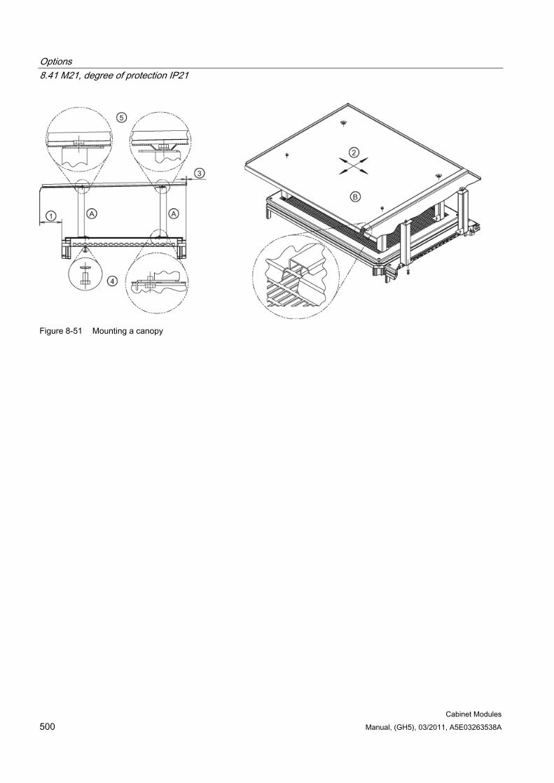
Options 8.41 M21, degree of protection IP21
Cabinet Modules 500 Manual, (GH5), 03/2011, A5E03263538A
Figure 8-51 Mounting a canopy
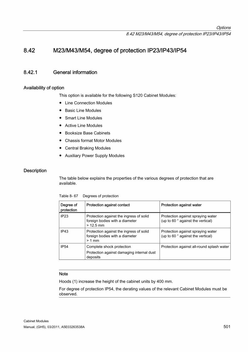
Options 8.42 M23/M43/M54, degree of protection IP23/IP43/IP54
Cabinet Modules Manual, (GH5), 03/2011, A5E03263538A 501
8.42 M23/M43/M54, degree of protection IP23/IP43/IP54
8.42.1 General information
Availability of option This option is available for the following S120 Cabinet Modules:
Line Connection Modules
Basic Line Modules
Smart Line Modules
Active Line Modules
Booksize Base Cabinets
Chassis format Motor Modules
Central Braking Modules
Auxiliary Power Supply Modules
Description The table below explains the properties of the various degrees of protection that are available.
Table 8- 67 Degrees of protection
Degree of protection
Protection against contact Protection against water
IP23 Protection against the ingress of solid foreign bodies with a diameter > 12.5 mm
Protection against spraying water (up to 60 ° against the vertical)
IP43 Protection against the ingress of solid foreign bodies with a diameter > 1 mm
Protection against spraying water (up to 60 ° against the vertical)
IP54 Complete shock protection Protection against damaging internal dust deposits
Protection against all-round splash water
Note
Hoods (1) increase the height of the cabinet units by 400 mm.
For degree of protection IP54, the derating values of the relevant Cabinet Modules must be observed.
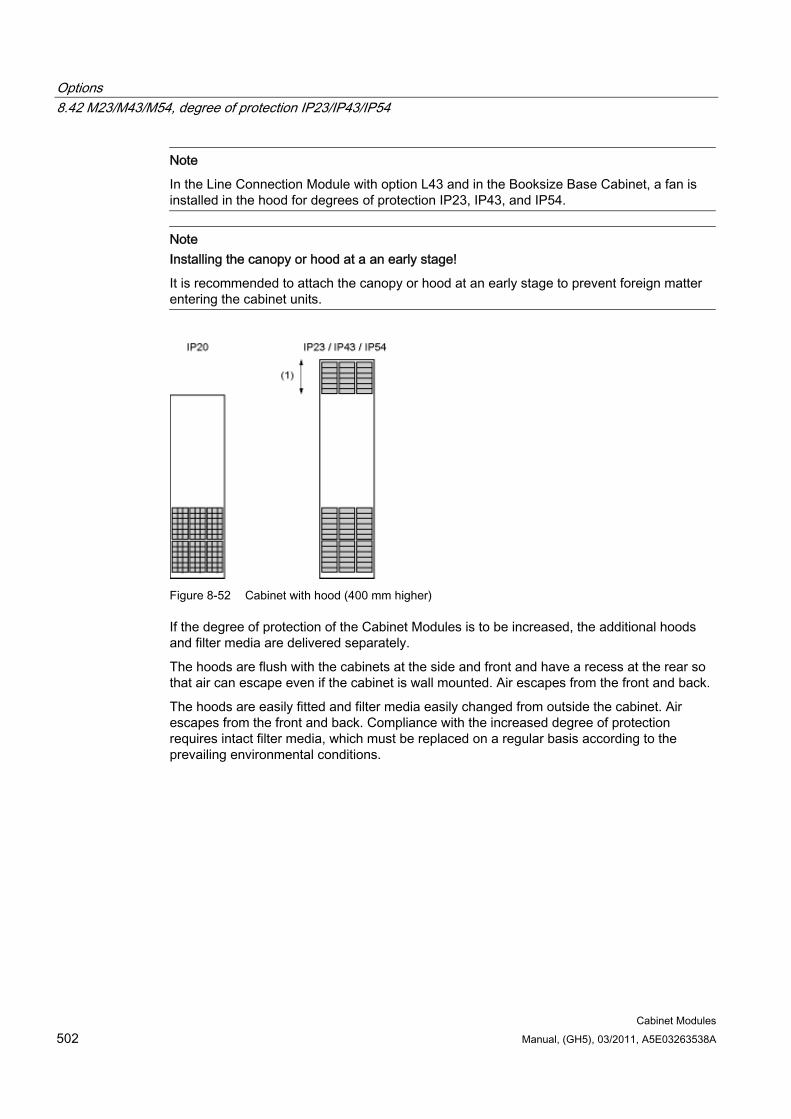
Options 8.42 M23/M43/M54, degree of protection IP23/IP43/IP54
Cabinet Modules 502 Manual, (GH5), 03/2011, A5E03263538A
Note
In the Line Connection Module with option L43 and in the Booksize Base Cabinet, a fan is installed in the hood for degrees of protection IP23, IP43, and IP54.
Note Installing the canopy or hood at a an early stage!
It is recommended to attach the canopy or hood at an early stage to prevent foreign matter entering the cabinet units.
Figure 8-52 Cabinet with hood (400 mm higher)
If the degree of protection of the Cabinet Modules is to be increased, the additional hoods and filter media are delivered separately.
The hoods are flush with the cabinets at the side and front and have a recess at the rear so that air can escape even if the cabinet is wall mounted. Air escapes from the front and back.
The hoods are easily fitted and filter media easily changed from outside the cabinet. Air escapes from the front and back. Compliance with the increased degree of protection requires intact filter media, which must be replaced on a regular basis according to the prevailing environmental conditions.
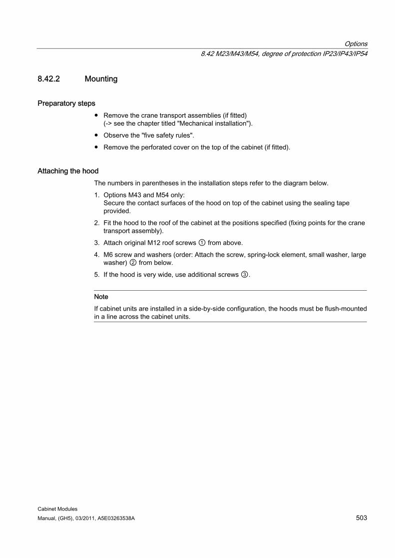
Options 8.42 M23/M43/M54, degree of protection IP23/IP43/IP54
Cabinet Modules Manual, (GH5), 03/2011, A5E03263538A 503
8.42.2 Mounting
Preparatory steps Remove the crane transport assemblies (if fitted)
(-> see the chapter titled "Mechanical installation").
Observe the "five safety rules".
Remove the perforated cover on the top of the cabinet (if fitted).
Attaching the hood The numbers in parentheses in the installation steps refer to the diagram below.
1. Options M43 and M54 only: Secure the contact surfaces of the hood on top of the cabinet using the sealing tape provided.
2. Fit the hood to the roof of the cabinet at the positions specified (fixing points for the crane transport assembly).
3. Attach original M12 roof screws ① from above.
4. M6 screw and washers (order: Attach the screw, spring-lock element, small washer, large washer) ② from below.
5. If the hood is very wide, use additional screws ③.
Note
If cabinet units are installed in a side-by-side configuration, the hoods must be flush-mounted in a line across the cabinet units.
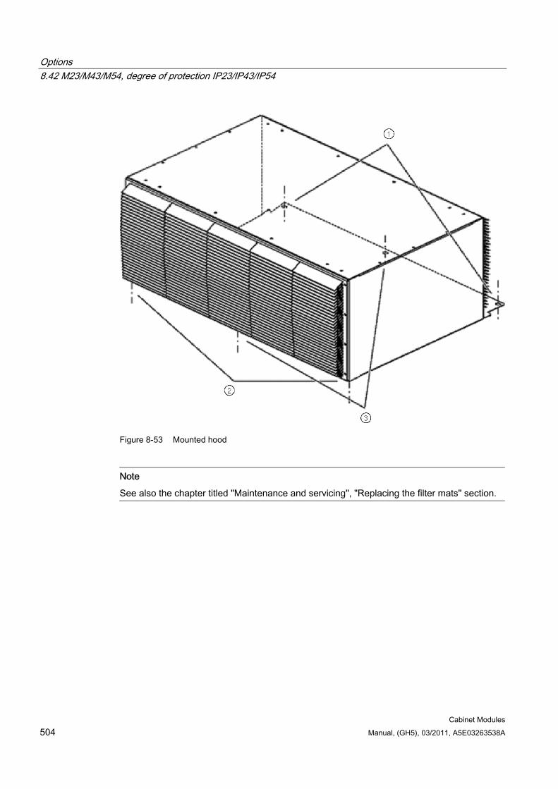
Options 8.42 M23/M43/M54, degree of protection IP23/IP43/IP54
Cabinet Modules 504 Manual, (GH5), 03/2011, A5E03263538A
Figure 8-53 Mounted hood
Note
See also the chapter titled "Maintenance and servicing", "Replacing the filter mats" section.
Options 8.43 M26/M27, side panels mounted on right and left
Cabinet Modules Manual, (GH5), 03/2011, A5E03263538A 505
8.43 M26/M27, side panels mounted on right and left
Availability of option This option is available for the following S120 Cabinet Modules:
Line Connection Modules
Basic Line Modules
Smart Line Modules
Active Line Modules
Booksize Base Cabinets
Chassis format Motor Modules
Central Braking Modules
Auxiliary Power Supply Modules
Description The side panels (option M26 = side panel mounted on the right; option M27 = side panel mounted on the left) are fitted at either end of a side-by-side cabinet unit configuration.
With the option M26, the Cabinet Module is fitted with a side panel on the right.
With the option M27, the Cabinet Module is fitted with a side panel on the left.
DANGER For each cabinet row installed, you must mount one side panel on the right (option M26) and one on the left (option M27).
For Cabinet Modules that are delivered with a side panel, the DC connection clamp is omitted from the side panel. If the installation sequence is modified and the side panel removed, then a DC connection clamp must be inserted!
Options 8.44 M59, closed cabinet door, air inlet from below through floor opening
Cabinet Modules 506 Manual, (GH5), 03/2011, A5E03263538A
8.44 M59, closed cabinet door, air inlet from below through floor opening
Availability of option This option is available for the following S120 Cabinet Modules:
Line Connection Modules
Basic Line Modules
Smart Line Modules
Active Line Modules
Booksize Base Cabinets
Chassis format Motor Modules
Central Braking Modules
Auxiliary Power Supply Modules
Description The standard cabinet units are supplied with integrated ventilation grilles in the bottom of the doors as standard.
With option M59, the Cabinet Modules are delivered with closed doors.
Safety information
WARNING When closed doors are used, the base plates, which are available as standard for ensuring a sufficient cooling air supply, are not required.
In this case, the customer must ensure that no dirt/conductive dust or moisture can enter the Cabinet Module. Cables must not be routed in such a way that they impede the flow of air through the cabinet floor opening.
If the area beneath the Cabinet Modules can be accessed, the customer must provide shock protection.
The required ambient conditions must be taken into account to prevent, for example, overheating of the cabinet and the ingress of dirt or moisture.
When removing doors, take care not to damage the grounding strips attached to them. Make sure that the strips are reattached properly when the doors are mounted.
Options 8.45 M60, additional shock protection
Cabinet Modules Manual, (GH5), 03/2011, A5E03263538A 507
Note
The door opening angle with free-standing cabinet units is 180°.
With a side-by-side configuration of the cabinet units, this opening angle is 130°.
For degrees of protection IP23/IP43/IP54 and with option L37 (DC interface incl. pre-charging input circuit), the door opening angle is only 110°.
8.45 M60, additional shock protection
Availability of option This option is available for the following S120 Cabinet Modules:
Line Connection Modules
Basic Line Modules
Smart Line Modules
Active Line Modules
Chassis format Motor Modules
Description The standard Cabinet Modules are designed according to BGV A 3. With option M60, additional covers (out of reach of accessible control and contact elements) are installed upstream of the power unit.
Safety information
Note
The additional shock protection (option M60) is not a substitute for the cabinet door(s). Cabinets must not be operated without cabinet door(s).
Options 8.46 M70, EMC shield bus
Cabinet Modules 508 Manual, (GH5), 03/2011, A5E03263538A
8.46 M70, EMC shield bus
8.46.1 General information
Availability of option This option is available for the following S120 Cabinet Modules:
Line Connection Modules
Booksize Base Cabinets
Chassis format Motor Modules
Auxiliary Power Supply Modules
Description With option M70, an EMC shield bus is incorporated for the use of shielded power cables for power cables and motor supply cables.
The cable shields for the cables routed to the cabinet must be connected to the EMC shield bus in accordance with EMC guidelines.
8.46.2 Connecting the cables to the EMC shield bus
Preparatory steps Observe the "five safety rules".
Allow unimpeded access to the EMC shield bus (if necessary, remove the protective covers during installation work)
Securing the cables to the shield bus 1. Remove approximately 5 cm of the protective sheath of the cable around the shield bus.
2. Place the shielded cable on the shield bus.
3. Snap the clip into the opening provided and tighten it.
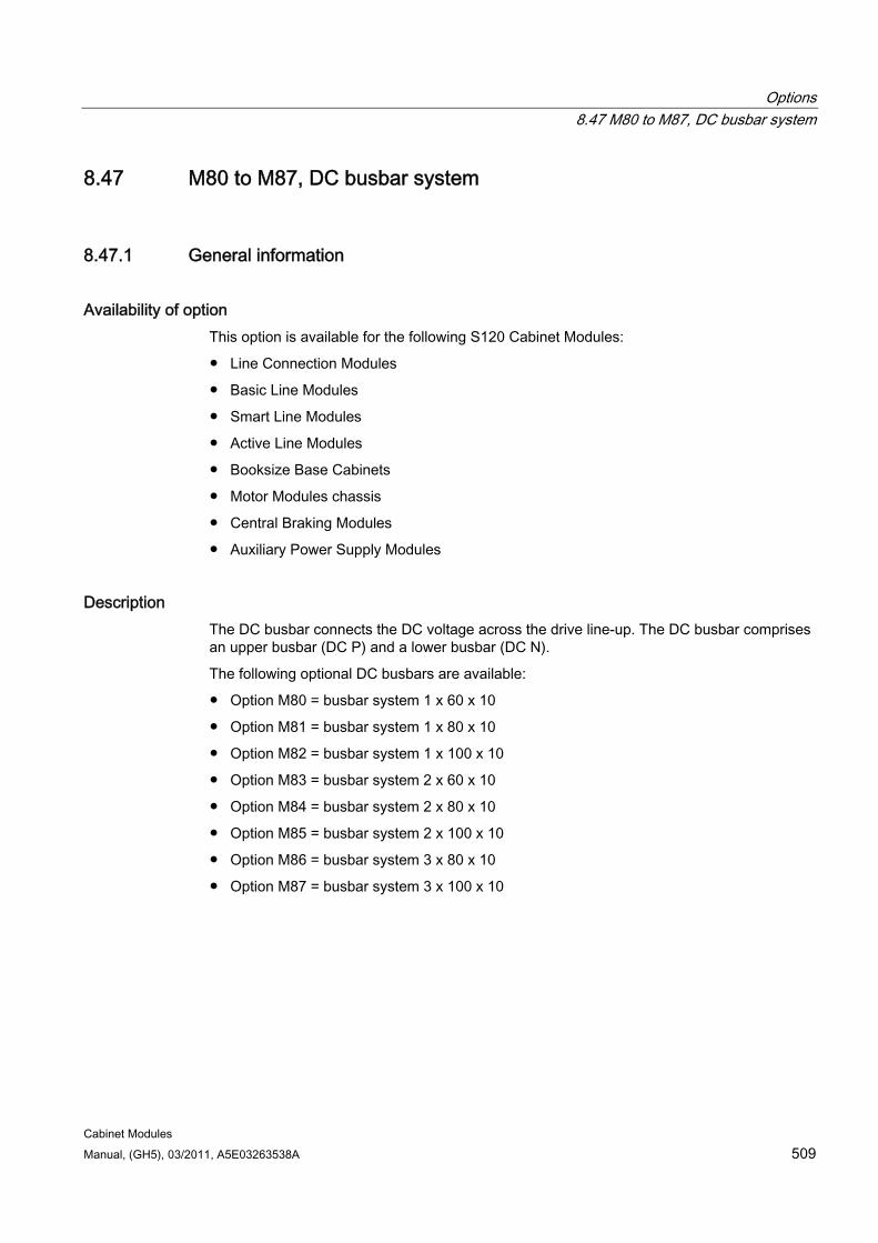
Options 8.47 M80 to M87, DC busbar system
Cabinet Modules Manual, (GH5), 03/2011, A5E03263538A 509
8.47 M80 to M87, DC busbar system
8.47.1 General information
Availability of option This option is available for the following S120 Cabinet Modules:
Line Connection Modules
Basic Line Modules
Smart Line Modules
Active Line Modules
Booksize Base Cabinets
Motor Modules chassis
Central Braking Modules
Auxiliary Power Supply Modules
Description The DC busbar connects the DC voltage across the drive line-up. The DC busbar comprises an upper busbar (DC P) and a lower busbar (DC N).
The following optional DC busbars are available:
Option M80 = busbar system 1 x 60 x 10
Option M81 = busbar system 1 x 80 x 10
Option M82 = busbar system 1 x 100 x 10
Option M83 = busbar system 2 x 60 x 10
Option M84 = busbar system 2 x 80 x 10
Option M85 = busbar system 2 x 100 x 10
Option M86 = busbar system 3 x 80 x 10
Option M87 = busbar system 3 x 100 x 10
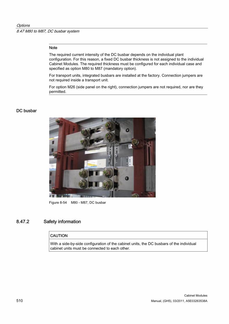
Options 8.47 M80 to M87, DC busbar system
Cabinet Modules 510 Manual, (GH5), 03/2011, A5E03263538A
Note
The required current intensity of the DC busbar depends on the individual plant configuration. For this reason, a fixed DC busbar thickness is not assigned to the individual Cabinet Modules. The required thickness must be configured for each individual case and specified as option M80 to M87 (mandatory option).
For transport units, integrated busbars are installed at the factory. Connection jumpers are not required inside a transport unit.
For option M26 (side panel on the right), connection jumpers are not required, nor are they permitted.
DC busbar
Figure 8-54 M80 - M87, DC busbar
8.47.2 Safety information
CAUTION With a side-by-side configuration of the cabinet units, the DC busbars of the individual cabinet units must be connected to each other.
Options 8.48 M90, crane transport assembly (top-mounted)
Cabinet Modules Manual, (GH5), 03/2011, A5E03263538A 511
8.48 M90, crane transport assembly (top-mounted)
Availability of option This option is available for the following S120 Cabinet Modules:
Line Connection Modules
Basic Line Modules
Smart Line Modules
Active Line Modules
Booksize Base Cabinets
Chassis format Motor Modules
Central Braking Modules
Auxiliary Power Supply Modules
Description A top-mounted crane transport assembly can be ordered as an option for Cabinet Modules.
Depending on the width of the module, the crane transport assembly consists of either transport eyebolts (for cabinet width ≤ 800 mm) or transport rails (for cabinet width > 800 mm).
Note
A crane transport assembly is included if transport units are supplied (option Y11).
Safety information
WARNING The transport rails are heavy and must be removed very carefully.
Options 8.49 N52, DC link fuses for Basic Line Modules
Cabinet Modules 512 Manual, (GH5), 03/2011, A5E03263538A
8.49 N52, DC link fuses for Basic Line Modules
Availability of option This option is available for the following S120 Cabinet Modules:
Basic Line Modules
Description Fuses are installed on the DC side to protect the Basic Line Module.
Installation of DC fuses is recommended if the DC current load in the configured drive line-up can be larger than the rated DC link current of the Basic Line Module.
Furthermore, the DC fuses protect the Basic Line Module against an overvoltage on the DC busbar of the drive line-up in the event of a malfunction.
Options 8.50 P10, measuring instrument for line values (installed in the cabinet doors)
Cabinet Modules Manual, (GH5), 03/2011, A5E03263538A 513
8.50 P10, measuring instrument for line values (installed in the cabinet doors)
Availability of option This option is available for the following S120 Cabinet Modules:
Line Connection Modules
Description The measuring instrument "DIRIS A40" with display, installed in the cabinet door of the Line Connection Module, acquires measured values of the power supply. In addition to these measured values, additional plant values (such as power and power factor, etc.) are calculated from the measured values using powerful, state-of-the art microprocessors. The measuring instrument is equipped with a serial RS485 interface with JBUS/MODBUS ®, which supports a max. transmission rate of 38.4 kbaud.
The device can measure the following as standard:
Actual currents per phase and actual currents of the neutral conductor
Average currents and maximum currents over programmable time intervals from 8 to 30 min.
Phase-to-neutral voltages and phase-to-phase voltages
Frequency (Hz)
Four-quadrant measurement of the actual, average, and maximum active power (+/-), reactive power (+/-) and apparent power per phase and in total over programmable time intervals from 8 to 30 min.
Display of active energy in kWh.
Power factor (PF) per phase and in total with the specifications "L" for inductive and "C" for capacitive
Note
Current transformers are required in the Line Connection Module to measure line currents. Option L41 (current transformer upstream of the main switch) is included in option P10. The measuring instrument "DIRIS A40" is wired according to connection type 3NBL/4NBL in the factory.
The current transformers must not be operated unloaded.
Note
Detailed and comprehensive instructions and information regarding the "DIRIS A40" measuring instrument can be found in the accompanying operating instructions, These operating instructions are available as additional documentation on the customer DVD supplied with the device.
Options 8.51 P11, measuring instrument for line values with PROFIBUS connection (installed in the cabinet door)
Cabinet Modules 514 Manual, (GH5), 03/2011, A5E03263538A
8.51 P11, measuring instrument for line values with PROFIBUS connection (installed in the cabinet door)
Availability of option This option is available for the following S120 Cabinet Modules:
Line Connection Modules
Description A measuring instrument "SENTRON PAC3200" with display, installed in the cabinet door of the Line Connection Module, acquires measured values of the power supply. In addition to these measured values, additional plant values (such as power and power factor, etc.) are calculated from the measured values using powerful, state-of-the art microprocessors. The measuring instrument has a PROFIBUS interface that enables a transfer rate of up to 12 Mbit/s.
The device can measure the following as standard:
Actual currents per phase and actual currents of the neutral conductor
Average currents and maximum currents over programmable time intervals from 1 to 60 min.
Phase-to-neutral voltages and phase-to-phase voltages
Frequency (Hz)
Four-quadrant measurement of the actual, average, and maximum active power (+/-), reactive power (+/-) and apparent power (+/-) per phase and in total over programmable time intervals from 1 to 60 min.
Display of active energy in kWh
Power factor (PF) per phase and in total with the specifications "L" for inductive and "C" for capacitive
Note
Current transformers are required in the Line Connection Module to measure line currents. Option L41 (current transformer upstream of the main switch) is included in option P11. The measuring instrument "SENTRON PAC3200" is wired according to connection type 3P3W in the factory.
The current transformers must not be operated unloaded.
Note
Detailed and comprehensive instructions and information regarding the "SENTRON PAC3200" measuring instrument can be found in the accompanying operating instructions, These operating instructions are available as additional documentation on the customer DVD supplied with the device.
Options 8.52 Y11, factory assembly into transport units
Cabinet Modules Manual, (GH5), 03/2011, A5E03263538A 515
8.52 Y11, factory assembly into transport units
Availability of option This option is available for the following S120 Cabinet Modules:
Line Connection Modules
Basic Line Modules
Smart Line Modules
Active Line Modules
Booksize Base Cabinets
Chassis format Motor Modules
Central Braking Modules
Auxiliary Power Supply Modules
Description Cabinet Modules can be ordered as factory-assembled transport units with a maximum width of up to 2400 mm. In this case, the relevant modules are shipped as interconnected units (both electrically and mechanically).
Note
No additional wiring between the Cabinet Modules is required, with the exception of the DRIVE-CLiQ connections used to interconnect the cabinets.
A crane transport assembly in the form of a crane transport rail is already included if transport units are supplied.
Table 8- 68 Installation sequence of the transport unit
Plain text required to order TU 1 - 1...6 Transport unit TU Consecutive number of the transport unit 1 - Position of the Cabinet Module within the transport unit 1 ... 6

Options 8.52 Y11, factory assembly into transport units
Cabinet Modules 516 Manual, (GH5), 03/2011, A5E03263538A
Cabinet Modules Manual, (GH5), 03/2011, A5E03263538A 517
Index
A Accessory kit
Original roof screws, 52 Active Interface Modules
LEDs, 346 Active Line Modules, 27
Cable routing, 105 Connection example, 168 Customer terminal block (X55), 110, 111 Description, 167 DRIVE-CLiQ connections and signal cables, 108, 109 Integration, 168 Options, 178 Parallel connection to increase power rating, 174 PROFIBUS or PROFINET connection to the Control Unit, 106, 107 Technical data, 179 X41, 176 X55 (customer terminal block), 110, 111
AOP30, 371, 437, 443 AOP30 advanced operator panel, 371 ARC detection (arc sensor), 473 Arc sensor (ARC detection), 474 Auxiliary power module
Basic Line Modules, 77 Connecting cables, 75 Connections, 75 Description, 71 Fuse, 74 Line Connection Module, 73 X100, 72 X101, 72
Auxiliary Power Supply Modules Cable routing, 121 Configuration, 246 Configuration example, 247 Connection example, 245 Customer terminals, 251 Description, 244 Fuse switch disconnector (-Q1), 248 Integration, 245 Line infeed, 121 Options, 252 Technical data, 253
Terminal blocks X45, X46, X47, 122 X45, X46, X47, 122
Auxiliary power supply system Availability, 70 Description, 71, 250 Fuse protection, 250 Infeed for supplying power, 77 Side-by-side installation of cabinet units, 76
B B51
VSM10, 393 Basic Line Modules, 24
Cable routing, 97 Connection example, 141 Customer terminal block (X55), 100 Description, 140 DRIVE-CLiQ connections and signal cables, 99 Integration, 141 Options, 148 Parallel connection to increase power rating, 144 PROFIBUS or PROFINET connection to the Control Unit, 98 X41, 146 X55 (customer terminal block), 100
Benefits, 23 Booksize Base Cabinets, 29, 188
Technical data, 194 Booksize Cabinet Kits, 29, 188
Cable routing, 112 Braking Modules, 28
Connection example, 483 LEDs, 345 Response thresholds, 231, 479 X21, 482
Braking resistor Cable length (max.), 237 Cable routing, 119 Configuring the "Overtemperature" checkback, Connection, 477, 486 Connection example, 483 Description, 236, 484 Dimension drawings, 484 Dimensions, 488 Duty cycle, 238, 489 PD, switch-on ratio of the braking resistor, 232 Power connections, 239
Index
Cabinet Modules 518 Manual, (GH5), 03/2011, A5E03263538A
R1, 487 R2, 487 Setting of the switch-on ratio, 232 Technical data, 240
Braking units, 476 Description, 476 Dimensions, 488 Technical data, 488
Breakaway torques, 221
C Cabinet anti-condensation heating, 475 Cabinet Modules
Connection overview, 63 System structure, 32
Cable and screw terminals, 257 Cable marshaling compartment, 494 Cable routing, 93
Active Line Modules, 105 Auxiliary Power Supply Modules, 121 Basic Line Modules, 97 Basic rules, 93 Booksize Cabinet Kits, 112 Braking resistor, 119 Central Braking Modules, 119 Chassis format Motor Modules, 112 Line Connection Modules, 94 Motor cable, 112 Safe Torque Off and Safe Stop 1, 116 Smart Line Modules, 101 Terminal blocks X45, X46, X47, 122 Terminal Module TM54F, 116
CBC10 Communication Board CAN bus, 353 Interface overview, 354 Option G20, 353
CBE20 Communication Board Installation, 358 Interface overview, 357 LEDs, 338 MAC address, 357 Option G33, 356 PROFINET, 356
Center of gravity of cabinet, 51 Central Braking Modules, 28
Cable length (max.), 237 Cable routing, 119 Configuration, 227 Connection example, 225 Description, 223 Duty cycle, 235
Integration, 225 Interface overview, 229 Interfaces, 228 LEDs, 345 Options, 233 Parallel connection, 228 Technical data, 234 Voltages and power ratings, 224 X2, 120 X5.1, 119 X5.2, 119
Chassis Cabinets, 29 Checklist
Electrical installation, 57 Mechanical installation, 42
Circuit breaker In withdrawable unit design, 446 Output-side, 447
CompactFlash card, 414, 430 Slot,
Connection Auxiliary power supply system, 75 Side-by-side installation of cabinet units, 53 To the foundation, 53
Connection work, 145, 159, 175, 191, 207, 251 Contactor feedback signal, 368 Control Interface Module
LEDs, Active Line Module, 342 LEDs, Basic Line Module, 340 LEDs, Smart Line Module, 341 Replacing, frame size FX, 284 Replacing, frame size GX, 286 Replacing, frame size HX, 288 Replacing, frame size JX, 290
Control Unit Replacing, 292
Control Unit CU320-2 DP, 404, 405 Description of the LED states, 331 LEDs after booting, 333 LEDs during booting, 332
Control Unit CU320-2 PN, 419, 420 Description of the LED states, 335 LEDs after booting, 336 LEDs during booting, 335
Crane transport aids, 51 Crane transport assembly (top-mounted), 511 CU320-2 DP, 405 CU320-2 PN, 420 Current transformer upstream of main breaker, 468 Customer terminal block -X55 (option G55), 360 Customer terminal block -X55 (Option G55), 359 Customer terminal block -X55.1, 192
Index
Cabinet Modules Manual, (GH5), 03/2011, A5E03263538A 519
D D14, 352 DC busbar, 67, 509, 510
Availability, 67 For side-by-side installation of cabinet units, 68
DC fuses Replacing, 318, 319
DC interface Commissioning, 467 Incl. pre-charging input circuit, 457 Principle of operation, 466 Replacing, 322
DC link capacitors Reforming, 326
DC link fuses, 512 Degrees of protection, 45, 501 Derating, 35 Derating data, 35
Current derating as a function of the installation altitude and ambient temperature, 35 Installation altitudes between 2000 m and 5000 m above sea level, 36 Permissible output current as a function of the ambient temperature, 36
Diagnostics, 331 using LEDs on Control Unit CU320-2 DP, 333 using LEDs on Control Unit CU320-2 PN, 336
Digital inputs/outputs, 410, 411, 425, 426 Direction of motor rotation, 80 Double Motor Module in Booksize Cabinet Kit format
Connection example, 187 DRIVE-CLiQ interface, 409, 424 Dust deposits, 256 Duty cycle
Braking resistor, 238 Motor Modules in booksize format, 198 Motor Modules in chassis format, 221
dv/dt filter compact plus Voltage Peak Limiter, 435 dv/dt filter plus voltage peak limiter, 441
E EMC shield bus, 508 EMERGENCY OFF pushbutton, 470 Encapsulated fuses, 316, 320 Encoder cable length (max.), 373, 383 Encoder interface -X520, 376, 380 ESD protective measures, 16 External EMERGENCY OFF, 129
F Fan
Replacing, Booksize Cabinet Kit, 293 Replacing, frame size FI, 307 Replacing, frame size GI, 309 Replacing, frame size HI, 311 Replacing, frame size HX - left, 301 Replacing, frame size HX - right, 303 Replacing, frame size JI, 313 Replacing, frame size JX, 305 Replacing, frame sizes FB, GB, GD, 297 Replacing, frame sizes FX, GX, 299
Field of application, 23 Filter mats, replacing, 261 Five safety rules, 18 Floor levelness, 46 Flying restart, 393 Forming the DC link capacitors, 326 Foundation, 53 Fuse switch disconnector, 127 Fuses in the fuse switch disconnector
Replacing, 317
G G20, 353 G33, 356 G55, 359 G56, 368 Grounded line supply, 84 Grounding switch, 471
Downstream of the internal main breaker, 472 Upstream of the internal main breaker, 471
H Hood, 503 HTL encoder, 382, 392
I Identification number, 326 Incremental encoder sin/cos 1 Vpp, 2,048, 381 Infeed
Auxiliary power supply system, 77 Installation
CBE20 Communication Board, 358 Line connection from above, 496
Installation device for power blocks, 260 Installation site, 44
Index
Cabinet Modules 520 Manual, (GH5), 03/2011, A5E03263538A
Insulation monitoring, 490 Interference suppression capacitor, disconnecting, 84 Internet addresses, 4 IP2 degree of protection, 498 IP20, 45 IP21, 45 IP23, IP43, IP54, 45, 501 IT line supply, 84
K K01 - K05, 369 K08, 371 K46, 373 K48, 378 K50, 382 K51, 393 K76, 395 K82, 397 K87, 398 K88, 400 K89, 402 K90, 404 K94, 418 K95, 419 KTY84-130 / PTC thermistor, 373
L L00, 434 L07, 435 L08/L09, 438 L10, 441 L13, 443 L22, 445 L25, 446 L34, 447 L37, 457 L41, 468 L42, 130, 469 L43, 131, 469 L44, 133, 469 L45, 470 L46, 471 L47, 471, 472 L51, 473 L55, 475 L61, L62, L64, L65, 476 L87, 490 LEDs, 331
Active Line Module, 342
Basic Line Module, 340 CBE20 Communication Board, 338 Central Braking Modules, 345 Control Unit CU320-2 DP, 333 Control Unit CU320-2 PN, 336 Motor Modules in booksize format, 344 Motor Modules in chassis format, 343 SITOP power supply unit, 350 Smart Line Module, 341 SMC10 Sensor Module, 347 SMC20 Sensor Module, 348 SMC30 Sensor Module, 349 TM54F, 350 Voltage Sensing Module in the Active Interface Module, 346
License code, 414, 430 Line Connection Modules
Cable routing, 94 Configuration example (frame size HL), 125 Configuration example (frame size JL), 126 Description, 124 Line infeed, 95 Options, 135 Technical data, 136 Versions, 130 X30, 96 X40, 96 X50, 96
Line infeed Cable routing, 95
Line Modules, 24 Line reactor, 445 LV HRC fuses, 321
M M06, 493 M07, 494 M13, 496 M21, 498, 499 M23, M43, M54, 501 M26, M27, 505 M59, 506 M60, 507 M70, 508 M80 - M87, 509 M90, 511 MAC address
CBE20 Ethernet interfaces, 357 Main contactor
Line Connection Modules < 800 A, 443 Maintenance and servicing, 255
Index
Cabinet Modules Manual, (GH5), 03/2011, A5E03263538A 521
Measuring instrument For line values, in cabinet door, 513 For line values, with PROFIBUS connection, 514
Measuring points, verification of isolation from supply, 464 Motor cable
Cable routing, 112 Connection, 78
Motor cable lengths, 439 Motor Modules, 29
Technical data, 212 X41, 362 X41 EP terminal / temperature sensor connection, 208 X46, 209, 363
Motor Modules in booksize format Configuration, 188 Description, 185 Duty cycle, 198 Integration, 186 LEDs, 344 Mounting grid arrangement in the cabinet, 190 Options, 193 Replacing, 264
Motor Modules in chassis format, 116 Cable lengths (min.), 206 Cable routing, 112 Configuration, 201 Connection example, 200 Customer terminal block (X55), 115 Description, 199 DRIVE-CLiQ connections and signal cables to the Control Unit, 114 High overload, 222 Integration, 200 LEDs, 343 Motor connection (U2/T1, 118 Options, 210 Parallel connection to increase power rating, 204 PROFIBUS or PROFINET connection to the Control Unit, 113 Signal cables to the SMC10/20/30 Sensor Module, 117 Small overload, 222 Terminal Module TM54F, 116 U2/T1, 118 X55 (customer terminal block), 115
Motor reactor, 438 Mounting
Canopy to increase the degree of protection to IP21, 499
Mounting grid arrangement in the cabinet, 190
Mounting rails, 51
N N52, 512
O Operation on an ungrounded line supply, 84 Option
D14, 352 G20, 353 G33, 356 G56, 368 K01 - K05, 369 K08, 371 K46, 373 K48, 378 K50, 382 K51, 393 K76, 395 K82, 397 K87, 398 K88, 400 K89, 402 K90, 404 K94, 418 K95, 419 L00, 434 L07, 435 L08/L09, 438 L10, 441 L13, 443 L22, 445 L25, 446 L34, 447 L37, 457 L41, 468 L42, L43, L44, 469 L45, 470 L46, L47, 471 L51, 473 L55, 475 L61, L62, L64, L65, 476 L87, 490 M06, 493 M07, 494 M13, 496 M21, 498 M23, M43, M54, 501 M26, M27, 505
Index
Cabinet Modules 522 Manual, (GH5), 03/2011, A5E03263538A
M59, 506 M60, 507 M70, 508 M80 - M87, 509 M90, 51, 511 N52, 512 P10, 513 P11, 514 X55, 359 Y11, 51, 515
Options Active Line Modules, 178 Auxiliary Power Supply Modules, 252 Basic Line Modules, 148 Booksize format Motor Modules, 193 Central Braking Modules, 233 Chassis format Motor Modules, 210 Line Connection Modules, 135 Overview, 30 Smart Line Modules, 162
Original roof screws, 52 Output-side circuit breaker, 447 Overload reserve, 221
P P10, 513 P11, 514 PE busbar, 64
Description, 64 External cables, 66 For side-by-side installation of cabinet units, 65 General information, 64
Power block Installation device, 260 Replacing, frame size FB, 265 Replacing, frame size FX, 271 Replacing, frame size GX, 274 Replacing, frame size HX - left, 277 Replacing, frame size HX - right, 280 Replacing, frame size JX, 282 Replacing, frame sizes GB, GD, 268
Power units Replacing, 263
Pre-charging input circuit, 457 PROFINET
CBE20 Communication Board, 356 PROFINET interface, 429
Q Q1 (fuse switch disconnector), 248 Q7 (fuse switch disconnector), 457
R R1 (braking resistor), 487 R2 (braking resistor), 487 Rating plate, 326 Removal, 52 Replacement fuses, 315 Replacing, 258
Backup battery of the cabinet operator panel, 324 Control Interface Module, frame size FX, 284 Control Interface Module, frame size GX, 286 Control Interface Module, frame size HX, 288 Control Interface Module, frame size JX, 290 Control Unit, 292 DC fuses, 318, 319 DC interface, 322 Encapsulated fuses, 316, 320 Fan, Booksize Cabinet Kit, 293 Fan, frame size FI, 307 Fan, frame size GI, 309 Fan, frame size HI, 311 Fan, frame size HX - left, 301 Fan, frame size HX - right, 303 Fan, frame size JX, 305, 313 Fan, frame sizes FB, GB, GD, 297 Fan, frame sizes FX and GX, 299 Filter mats, 261 Fuses in the fuse switch disconnector, 317 LV HRC fuses, 321 Motor Modules in booksize format, 264 Power block, frame size FB, 265 Power block, frame size FX, 271 Power block, frame size GX, 274 Power block, frame size HX - left, 277 Power block, frame size HX - right, 280 Power block, frame size JX, 282 Power block, frame sizes GB, GD, 268 Power units, 263 Pre-charging resistors of the DC interface, 323 Replacement fuses, 315
Replacing the fan, 294, 295 Required room height, 45 Requirements, 15 Residual risks, 19 Resolver, 373
Connection example, 377 RS 232, 371
Index
Cabinet Modules Manual, (GH5), 03/2011, A5E03263538A 523
S S1 (reset key), 230 S1 (threshold switch), 478 S2 (reset key), 231 S3 (braking resistor monitoring), 232 Safe Brake Adapter, 400, 402
230 V AC, 400 24 V DC, 402
Safe Brake Control, 400, 402 Safe STOP 1, 397 Safe Torque Off, 397 Safety Integrated functions, 397 Safety precautions, 42 Safety regulations, 17 Saving the parameter settings, 416, 432 SBC (Safe Brake Control), 400, 402 Serial interface (RS232), 371, 413, 428 Servicing, 256 Shipping and handling indicators, 47
Shock indicator, 47 Tilt indicator, 47
Shock indicator, 47 Shock protection, 507 Side panels, 505 SINAMICS S120 Cabinet Modules
Example of a drive line-up, 22 Main components, 21 Overview, 21 Parallel connection, 22 Power range extension, 22 System data, 33 Technical data, 33 Voltage ranges and power ratings, 22
Single Motor Module in Booksize Cabinet Kit format Connection example, 186
SITOP power supply unit LEDs, 350
SIZER, 414, 430 Smart Line Modules, 26
Cable routing, 101 Connection example, 154 Customer terminal block (X55), 104 Description, 153 DRIVE-CLiQ connections and signal cables to the Control Unit, 103 Integration, 154 Options, 162 Parallel connection to increase power rating, 158 PROFIBUS or PROFINET connection to the Control Unit, 102 Technical data, 163 X41, 160
X55 (customer terminal block), 104 SMC10, 373
Interface overview, 375 SMC10 Sensor Module
Description, 373 LEDs, 347
SMC20, 378 Interface overview, 379
SMC20 Sensor Module Description, 378 LEDs, 348
SMC30, 382 Interface overview, 388
SMC30 Sensor Module Description, 382 LEDs, 349
SMC30 sensor module for detecting the actual motor speed (option K50), 382 SS1 (Safe Stop 1) (time-controlled), 397 SSI encoder, 382 STARTER, 414, 416, 431, 432, 437, 443
System requirements, 415, 431 STO (Safe Torque Off), 397 Storage, 41 Switch disconnector, 460 System data
SINAMICS S120 Cabinet Modules, 33 System structure, 32
T T1 (thermostatic switch connection), 487 T2 (thermostatic switch connection), 487 T2 (transformer), 248 Technical data
Active Line Modules, 179 Auxiliary Power Supply Modules, 253 Basic Line Modules, 149 Booksize Base Cabinets, 194 Braking resistors, 240 Braking units, 488 Central Braking Modules, 234 Line Connection Modules, 136 Motor Modules, 212 SINAMICS S120 Cabinet Modules, 33 Smart Line Modules, 163
Technical support, 4 Terminal block -X50, 127 Terminal blocks X45, X46, X47
Cable routing, 122 Terminal Module TM54F, 398
Index
Cabinet Modules 524 Manual, (GH5), 03/2011, A5E03263538A
Thermostatic switch Connection, 487
Tilt indicator, 47 TM54F
LEDs, 350 Tool, 49, 256 Transformer (-T2), 248
Tap, 248 Transformer for voltage adaptation (-T2), 248 Transport, 39 Transport eyebolts, 51 Transport unit, 515 Transport units, 51 TTL encoder, 382, 392
V Ventilation, 256 Voltage Peak Limiter, 435, 441 Voltage Sensing Module
K51, 393 LEDs, 346
VSM10, 393
X X1 (supply infeed), 124 X10 (thermostatic switch checkback contact), 239 X100, 72, 409, 424 X100 (LCM), 74 X101, 73, 409, 424 X101 (auxiliary power module), 76 X102, 409, 424 X103, 409, 424 X120 (EMERGENCY OFF pushbutton in the cabinet door), 470 X122, 410, 425 X132, 411, 426 X140, 413, 428 X1400 (Ethernet interface), 357 X150, 429 X2 (control terminals), 230 X2 (terminal block), 120 X2/X4 (motor connection), 440 X21 (Braking Modules), 482 X21 (digital inputs/outputs), 477 X240 (cabinet anti-condensation heating), 475 X30
Cable routing, 96 X30 (external EMERGENCY OFF), 129 X4 (digital inputs/outputs), 364
X40 Cable routing, 96
X40 (external 230 V AC auxiliary infeed), 129 X41, 362 X41 (Active Line Modules), 176 X41 (Basic Line Modules), 146 X41 (Motor Module - chassis format), 208 X41 (Smart Line Modules), 160 X42 (X46 Brake control and monitoring), 363 X45, 122 X45 (for tapping the line voltage), 251 X451 (CAN bus), 355 X452 (CAN bus), 355 X46, 122 X46 (brake control and monitoring), 209 X46 (power supply for SITOP), 251 X47, 122 X47 (for tapping the 230 V AC, 1-phase voltage), 251 X5 (braking resistor connection), 230 X5 (digital inputs/outputs), 366 X5.1, 119 X5.2, 119 X50
Cable routing, 96 X50 ("circuit breaker" checkback contact), X50 ("Fuse switch disconnector" checkback contacts), X50 ("main contactor" checkback contact), X50 (checkback contact), 127, 129 X520, 382
SMC30, 389 X520 (encoder interface), 376 X520 (SMC20), 380 X521, 382, 390 X531, 382, 391 X55, 359, 360 X55.1/ (temperature monitoring), 191 X60 (line current transformer), 469 X70 (Grounding switch upstream of internal main breaker), 472 X71 (Grounding switch downstream of internal main breaker), 473
Y Y11, 515


www.siemens.com/automation
Subject to change without prior notice© Siemens AG 2011
Siemens AGIndustry SectorDrive TechnologiesLarge DrivesPostfach 474390025 NUREMBERGGERMANY