sinec s1 master module cp 2433 - siemens ag · sinec s1 master module cp 2433 ... information for...
TRANSCRIPT
C79000-G8976-C063
Release 01Volume 1 of 1
SINEC is a trademark of SIEMENS
Siemens Aktiengesellschaft
SINEC
SINEC S1 Master Module CP 2433
Introduction
Master module CP 2433
Appendix
PICS
Abbreviations /Terms
Further reading
Notes on the CE Marking
A
B
1
C
2
D


SINEC
SINEC S1 Master Modul CP 2433
Manual C79000-B8976-C086

Note
We would point out that the contents of this product documentation shall not become a part of ormodify any prior or existing agreement, commitment or legal relationship. The Purchase Agreementcontains the complete and exclusive obligations of Siemens. Any statements contained in thisdocumentation do not create new warranties or restrict the existing warranty.
We would further point out that, for reasons of clarity, these operating instructions cannot deal withevery possible problem arising from the use of this device. Should you require further informationor if any special problems arise which are not sufficiently dealt with in the operating instructions,please contact your local Siemens representative.
GeneralThis device is electrically operated. In operation, certain parts of this device carry adangerously high voltage.
Failure to heed warnings may result in serious physical injury and/or material damage.
Only appropriately qualified personnel may operate this equipment or work in itsvicinity. Personnel must be thoroughly familiar with all warnings and maintenancemeasures in accordance with these operating instructions.
Correct and safe operation of this equipment requires proper transport, storage andassembly as well as careful operator control and maintenance.
Personnel qualification requirements
Qualified personnel as referred to in the operating instructions or in the warning notes are definedas persons who are familiar with the installation, assembly, startup and operation of this productand who posses the relevant qualifications for their work, e.g.:
- Training in or authorization for connecting up, grounding or labelling circuits and devices orsystems in accordance with current standards in saftey technology;
- Training in or authorization for the maintenance and use of suitable saftey equipment inaccordance with current standards in safety technology;
- First Aid qualification.
WARNING !
!
B8976-C086 Contents
I-1
CONTENTS
1. INTRODUCTION .....................................................................................1-1
1.1 General ...................................................................................................................1-21.1.1 Overview of the Chapters...................................................................................1-21.1.2 Conventions used in the Text.............................................................................1-21.1.3 Requirements ....................................................................................................1-21.1.4 Further Information ............................................................................................1-21.1.5 Hotline ...............................................................................................................1-2
2. MASTER MODULE CP 2433...................................................................2-1
2.1 Overview of the Module and Interface Software..................................................2-22.1.1 Introduction........................................................................................................2-22.1.2 Technical Data of the Module.............................................................................2-32.1.3 Slots Permitted for the CP 2433 in SIMATIC PLCs and in the ET200U ..............2-42.1.4 Installation of the CP ..........................................................................................2-62.1.5 Addressing the CP in the PLC............................................................................2-72.1.6 How the PLC Addresses the Slaves on the AS-I Cable ......................................2-72.1.7 Using the CP 2433 in the ET200U ...................................................................2-102.1.8 Control and Display Elements of the CP 2433 ..................................................2-122.1.9 Types of Operation with the CP 2433...............................................................2-16
2.2 CP 2433 Standard Operation...............................................................................2-172.2.1 Configuring the CP 2433 for Standard Operation .............................................2-172.2.2 Interface of the CP 2433 to the Application ......................................................2-192.2.3 Error Messages of the CP 2433 in Standard Operation....................................2-222.2.4 Starting up the CP 2433 in Standard Operation ...............................................2-282.2.5 Exchanging a Defective Slave/ Automatic Address Programming ....................2-282.2.6 Error Indicators of the CP 2433 in Standard Operation /
Remedy if Errors Occur ...................................................................................2-30
2.3 Extended Operation.............................................................................................2-322.3.1 Overview of the Functions................................................................................2-322.3.2 Programming the Interface...............................................................................2-332.3.3 Description of the FB Job Processing ..............................................................2-362.3.4 Interface of the Function Block FB60................................................................2-382.3.5 Structure of the Working Data Block ................................................................2-422.3.6 Instructions for Configuring and Programming .................................................2-43
2.3.6.1 How to Configure the CP 2433 with Function Block....................................2-432.3.6.2 Automatic Configuration when a CP 2433 is Replaced...............................2-442.3.6.3 Check List for Programming the CP 2433 with Function Block ...................2-44
2.3.7 Job: Write Parameters .....................................................................................2-452.3.7.1 Job: Configure Parameters ........................................................................2-45
2.3.8 Description of the “Command to CP” Jobs .......................................................2-462.3.8.1 Set_Permanent_Parameter........................................................................2-482.3.8.2 Get_Permanent_Parameter .......................................................................2-492.3.8.3 Write_Parameter........................................................................................2-502.3.8.4 Read_Parameter........................................................................................2-512.3.8.5 Store_Actual_Parameters ..........................................................................2-522.3.8.6 Set_Permanent_Configuration ...................................................................2-532.3.8.7 Get_Permanent_Configuration...................................................................2-542.3.8.8 Store_Actual_Configuration........................................................................2-552.3.8.9 Read actual configuration data...................................................................2-562.3.8.10 Set_LPS...................................................................................................2-57
Contents B8976-C086
I-2
2.3.8.11 Set_Offline_Mode ....................................................................................2-582.3.8.12 Select Autoprogramming..........................................................................2-592.3.8.13 Set_Operation_Mode ...............................................................................2-602.3.8.14 Change_Slave_Address...........................................................................2-612.3.8.15 Read Slave Status ...................................................................................2-622.3.8.16 Read Lists and Flags (Get_LPS, Get_LAS, Get_LDS, Get_Flags) .........2-632.3.8.17 Read List of ID Codes ..............................................................................2-652.3.8.18 Read List of I/O Configurations ................................................................2-662.3.8.19 Read Parameter Echo List .......................................................................2-672.3.8.20 Read Version ID.......................................................................................2-682.3.8.21 Slave Diagnostics.....................................................................................2-692.3.8.22 Read Slave Status and Delete..................................................................2-702.3.8.23 Read Slave ID..........................................................................................2-712.3.8.24 Read Slave I/O.........................................................................................2-72
2.3.9 Error Processing / Assignment of the Error Numbers.......................................2-73
A ASI PROTOCOL IMPLEMENTATION CONFORMANCE STATEMENT(PICS)..................................................................................................... A-1
A.1 PICS für CP 2433 .................................................................................................. A-1
B ABBREVIATIONS / TERMS....................................................................B-1
C FURTHER READING ..............................................................................C-1

B8976-C086 SINEC S1 Master Module CP 2433
1-1
1. Introduction
This chapter contains basic information and an introduction to the SINEC S1 system conceptand SINEC S1 components. The main aim of the manual is to describe the SINEC S1 mastercomponents.
We recommend the following procedure when ...
...You want an overall picture of SINEC S1. ´� Read the manual ‘SINEC S1/AS-IIntroduction and Basic Information’.Here, you will find general informationabout SINEC S1.
...You want to know how programs for theCP 2433 are created.
´� Read Section 1.5 ‘The Master Mode’ inChapter 1 of the manual ‘SINECS1/AS-I Introduction and BasicInformation’. Also read Chapters 2ofthis manual.
...You want to start up the PLC mastermodule CP 2433.
´� Section 2.1 ‘Overview of the Moduleand Interface Software’ and 2.2‘Standard Operation’ in Chapter 2contain the required information.
... You want to create a PLC program forstandard applications.
´� Section 2.2 contains all the informationrequired for standard operation.
SINEC S1 Master Module CP 2433 B8976-C086
1-2
1.1 General
1.1.1 Overview of the Chapters
Chapter 1 Introduction
This chapter provides basic information for the effective use of this manual.
Chapter 2 SINEC S1 Master Module CP 2433
This chapter provides an overview of the modes, installation and startup and the display andoperating elements of the CP 2430.
1.1.2 Conventions used in the Text
General symbols in the text:
�� This character indicates an action for you to perform.
��This character indicates special features and danger.
1.1.3 Requirements
Requirements for Understanding the Manual:
±� for the PLC master module: knowledge of STEP 5 programming
1.1.4 Further Information
You can obtain more detailed information from your local Siemens office, particularly aboutthe SINEC S1 components and other AS-I modules mentioned in this manual.
The order numbers for the products mentioned in this manual can be found in the currentcatalogs.
1.1.5 Hotline
If you have technical questions, please use our hotline on the following numbers:
xx49-9131-7-43147
xx49-9131-7-43157

B8976-C086 SINEC S1 Master Module CP 2433
2-1
2. Master Module CP 2433
This chapter explains the functions of the SINEC S1 master module CP 2433 and explainshow to use it.
You will learn the following:
±� Which PLC systems can be operated with the CP 2433 on SINEC S1.
±� How a SINEC S1 system can be used with minimum programming in CP 2433standard operation.
±� Which additional possibilities are provided by CP 2433 extended operation withSINEC S1.
±� How to deal with errors.

SINEC S1 Master Module CP 2433 B8976-C086
2-2
2.1 Overview of the Module and Interface Software
2.1.1 Introduction
The CP 2433 module can be operated in the programmable logic controllers (PLC) S5-90U,S5-95U, S5-100U and in the ET200U system (distributed peripherals). It allows connection ofan AS-I cable to these programmable controllers.
C P 2 433
P L C
C P 2 433
S IN E C L2-D P L2 -F M S
E T 200 U w ith L 2-D P / L 2 F M S in terface
S IN E C S 1
S IN E C S 1
Fig. 2-1 Possible Uses of the SINEC S1 Module CP 2433
Product Structure
The CP 2433 consists of the following components:
1. CP 2433 module
2. This manual including the function block for extended operation of the CP 2433
For further products refer to /3/ or consult your local Siemens office.

B8976-C086 SINEC S1 Master Module CP 2433
2-3
2.1.2 Technical Data of the Module
The CP 2433 module has the following technical characteristics:
±� The CP occupies both slots of a SIMATIC bus module.
±� The CP occupies 16 bytes in the analog area of the PLC.
±� The AS-I slave configuration is stored using a switch on the front panel.
±� The AS-I cable is connected to the terminal on the bus module of the PLC.
Further technical data:
Bus cycle time 5 ms with 31 slaves
Configuration By switch on the front panel or using thefunction block
Supported AS-I profiles without function block: M0with function block: M1
Interfaces
• AS-I connectionUsing S5 bus module;terminal 7-8; 9-10
Address area 16 bytes in the analog area of the PLC
Address ID for ET 200U PROFIBUS configuration 223
Power supply DC 9V via backplane bus
Permitted ambient conditions
• Operating temperature with horizontal installation 0 to 60°C
• Operating temperature with vertical installation 0 to 40°C
• Transport and storage temperature -40°C to +70°C
• Relative humidity max. 95% at +25°C
Current consumption typically 200 mA
Design
• Module format S5-100U type
• Dimensions (W x H x D) in mm 90 x 134 x 85
• Weight approx. 360 g
• Space required 2 slots
Table 2-1 Technical Data
SINEC S1 Master Module CP 2433 B8976-C086
2-4
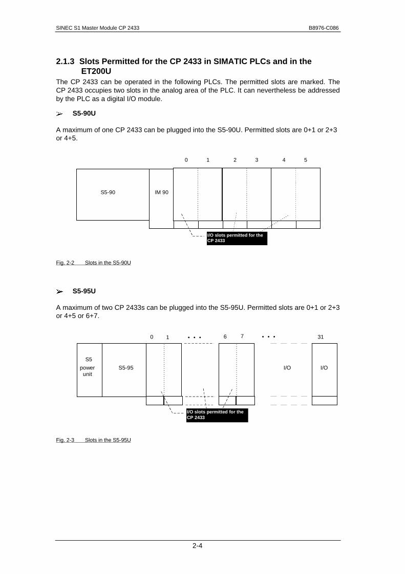
2.1.3 Slots Permitted for the CP 2433 in SIMATIC PLCs and in theET200U
The CP 2433 can be operated in the following PLCs. The permitted slots are marked. TheCP 2433 occupies two slots in the analog area of the PLC. It can nevertheless be addressedby the PLC as a digital I/O module.
±� S5-90U
A maximum of one CP 2433 can be plugged into the S5-90U. Permitted slots are 0+1 or 2+3or 4+5.
Fig. 2-2 Slots in the S5-90U
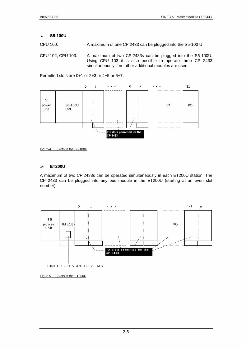
±�±� S5-95U
A maximum of two CP 2433s can be plugged into the S5-95U. Permitted slots are 0+1 or 2+3or 4+5 or 6+7.
Fig. 2-3 Slots in the S5-95U
S5-90 IM 90
0 1 2 3 4 5
I/O slots permitted for theCP 2433
S5-95 I/O
0 1 • • • 76 31
power unit
S5
• • •
I/O slots permitted for theCP 2433
I/O
B8976-C086 SINEC S1 Master Module CP 2433
2-5
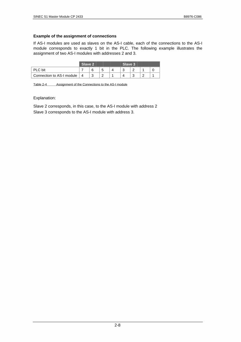
±�±� S5-100U
CPU 100: A maximum of one CP 2433 can be plugged into the S5-100 U
CPU 102, CPU 103: A maximum of two CP 2433s can be plugged into the S5-100U.Using CPU 103 it is also possible to operate three CP 2433simultaneously if no other additional modules are used.
Permitted slots are 0+1 or 2+3 or 4+5 or 6+7.
S5-100UCPU
I/O
0 1 • • • 76 31
power unit
S5
• • •
I/O slots permitted for theCP 2433
I/O
Fig. 2-4 Slots in the S5-100U
±�±� ET200U
A maximum of two CP 2433s can be operated simultaneously in each ET200U station. TheCP 2433 can be plugged into any bus module in the ET200U (starting at an even slotnumber).
IM 3 1 8 -Bp o w e r u n i t
S 5
S IN E C L 2 -D P /S IN E C L 2 -F M S
0 1 • • • nn -1
I /O s lo ts p e rm i t te d fo r th eC P 2 4 3 3
I /O
Fig. 2-5 Slots in the ET200U

SINEC S1 Master Module CP 2433 B8976-C086
2-6
2.1.4 Installation of the CP
The CP is plugged in to one of the permitted slots in the PLC. It is then secured by the screwon the front panel.
The AS-I cable is connected to the terminals of the bus module in which the CP is plugged in.It is connected to terminal pair 7,9 or 8,10 of the right slot of a SIMATIC bus module.Terminals 7 and 8 as well as 9 and 10 are electrically connected by the CP 2433 when it isplugged in.
The assignment of the pair of terminals and the polarity are indicated on the front panel of theCP. The second pair of terminals is intended for connecting the AS-I power unit or a branchof the AS-I cable. The AS-I power unit can, however, be connected at any point on the AS-Icable.
Fig. 2-6 Terminal Block with Connections and AS-I Cable
Installation
To install the CP, follow the steps outlined below:
�� Set the coding lock of the SIMATIC bus module in which you want to plug in the CP tothe value 6.
�� Install the CP on the bus module and secure it using the screw on the front panel.
���� Immunity to Interference/Grounding
�� To make sure that the CP 2433 is immune to interference, the PLC and AS-Ipower unit must be grounded correctly. For more detailed information refer tothe System Manuals of the PLCs and the description of the AS-I power unit. Onthe PLC, it is important that the rail to which the bus modules are clipped is wellgrounded.
CP 2433 Terminal block
7
8
9
10
ASI + ASI -
ASI + ASI -1 3 5 7
2 4 6 8 10
9 1 3 5 7 9
2 4 6 8 10
ASI + ASI -braun blauASI+ ASI-brown blue

B8976-C086 SINEC S1 Master Module CP 2433
2-7
2.1.5 Addressing the CP in the PLC
The CP 2433 occupies 16 bytes in the address area (analog area) of the PLC. The locationof these 16 bytes within the overall address area is determined by the slot position of theCP 2433. The following table indicates the addresses occupied depending on the selectedslot. The first address of the occupied address area is called the start address.
Slots occupied by CP
Start address Address area(I/O byte no.)
0 , 1 64 64 ... 79
2 , 3 80 80 ... 95
4 , 5 96 96 ... 111
6 , 7 112 112 ... 127
Table 2-2 Addresses Occupied Dependent on Slot
2.1.6 How the PLC Addresses the Slaves on the AS-I Cable
Each station (slave) on the AS-I cable is assigned 4 bits (a nibble) by the CP 2433. The PLCcan write (slave output data) and read (slave input data) this nibble. This allows bi-directionalslaves to be addressed.
This means that 31 x 4 bits of the 16 byte address area of the CP 2433 are occupied by theAS-I slave data. The remaining 4 bits are for control information and status acknowledgmentof the CP 2433 (control nibble/status nibble).
The following table illustrates the assignment of the CP 2433 interface (n is the slot-dependent start address of the CP address area). The table shows the assignment of theslave I/O bits to the I/O bytes of the PLC.
Byte number Bit 7-4 Bit 3-0
n+0 Control nibble/StatusBit 3 | Bit 2 | Bit 1 | Bit 0
Slave 1 Bit 3 | Bit 2 | Bit 1 | Bit 0
n+1 Slave 2 Slave 3
n+2 Slave 4 Slave 5
n+3 Slave 6 Slave 7
n+4 Slave 8 Slave 9
n+5 Slave 10 Slave 11
n+6 Slave 12 Slave 13
n+7 Slave 14 Slave 15
n+8 Slave 16 Slave 17
n+9 Slave 18 Slave 19
n+10 Slave 20 Slave 21
n+11 Slave 22 Slave 23
n+12 Slave 24 Slave 25
n+13 Slave 26 Slave 27
n+14 Slave 28 Slave 29
n+15 Slave 30Bit 3 | Bit 2 | Bit 1 | Bit 0
Slave 31Bit 3 | Bit 2 | Bit 1 | Bit 0
Table 2-3 Bit Assignment of the CP 2433 Interface
PLC I/O bits
Slave bits
SINEC S1 Master Module CP 2433 B8976-C086
2-8
Example of the assignment of connections
If AS-I modules are used as slaves on the AS-I cable, each of the connections to the AS-Imodule corresponds to exactly 1 bit in the PLC. The following example illustrates theassignment of two AS-I modules with addresses 2 and 3.
Slave 2 Slave 3
PLC bit 7 6 5 4 3 2 1 0
Connection to AS-I module 4 3 2 1 4 3 2 1
Table 2-4 Assignment of the Connections to the AS-I module
Explanation:
Slave 2 corresponds, in this case, to the AS-I module with address 2Slave 3 corresponds to the AS-I module with address 3.
B8976-C086 SINEC S1 Master Module CP 2433
2-9
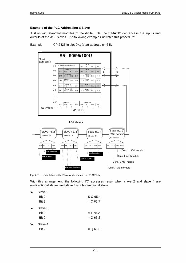
Example of the PLC Addressing a Slave
Just as with standard modules of the digital I/Os, the SIMATIC can access the inputs andoutputs of the AS-I slaves. The following example illustrates this procedure:
Example: CP 2433 in slot 0+1 (start address n= 64):
Bit 0Bit 1Bit 2Bit 3
Slave no. 2
Bit 0Bit 1Bit 2Bit 3
Slave no. 3
Bit 0Bit 1Bit 2Bit 3
Slave no. 4
Bit 0Bit 1Bit 2Bit 3
Slave no. 9
AS-I slaves
I/O code= 9H
Bit 0Bit 1Bit 2Bit 3Slave 5
Bit 0Bit 1Bit 2Bit 3Slave 7
Control/Status nibbleBit 0Bit 1Bit 2Bit 3
Slave 1
Bit 0Bit 1Bit 2Bit 3Slave 30
Bit 0Bit 1Bit 2Bit 3Slave 31
I/O bit no.I/O byte no.
n+15
n+5
n+2
n+1
n+0
7 6 5 4 3 2 1 0
S5 - 90/95/100UStart
Bit 0Bit 1Bit 2Bit 3Slave 8
Bit 0Bit 1Bit 2Bit 3Slave 9
n+4
Bit 0Bit 1Bit 2Bit 3Slave 6n+3
address n
Bit 0Bit 1Bit 2Bit 3Slave 2
Bit 0Bit 1Bit 2Bit 3Slave 3
Bit 0Bit 1Bit 2Bit 3Slave 4
Bit 0Bit 1Bit 2Bit 3Slave 10
Bit 0Bit 1Bit 2Bit 3Slave 11
(AS-I module)
Conn. 1 AS-I module
Conn. 2 AS-I module
Conn. 3 AS-I module
Conn. 4 AS-I module
I/O code= EH I/O code= 8HI/O code= 0H
used as output
used as input
used as output
used as output
Used bidirectionally
Fig. 2-7 Simulation of the Slave Addresses on the PLC Slots
With this arrangement, the following I/O accesses result when slave 2 and slave 4 areunidirectional slaves and slave 3 is a bi-directional slave:
±� Slave 2
Bit 0 S Q 65.4
Bit 3 = Q 65.7
±� Slave 3
Bit 2 A I 65.2
Bit 2 = Q 65.2
±� Slave 4
Bit 2 = Q 66.6
SINEC S1 Master Module CP 2433 B8976-C086
2-10
2.1.7 Using the CP 2433 in the ET200U
Addressing
The CP 2433 occupies 2 slots and a total of 16 input and output bytes in the ET200. The 16input bytes contain the status nibble and the input data of the slave. The 16 output bytescontain the control nibble and output data of the slaves.
Byte number Bit 7-4 Bit 3-0
n+0 Status nibbleBit 3 | Bit 2 | Bit 1 | Bit 0
Slave 1 Bit 3 | Bit 2 | Bit 1 | Bit 0
n+1 Slave 2 Slave 3
n+2 Slave 4 Slave 5
n+3 Slave 6 Slave 7
n+4 Slave 8 Slave 9
n+5 Slave 10 Slave 11
n+6 Slave 12 Slave 13
n+7 Slave 14 Slave 15
n+8 Slave 16 Slave 17
n+9 Slave 18 Slave 19
n+10 Slave 20 Slave 21
n+11 Slave 22 Slave 23
n+12 Slave 24 Slave 25
n+13 Slave 26 Slave 27
n+14 Slave 28 Slave 29
n+15 Slave 30Bit 3 | Bit 2 | Bit 1 | Bit 0
Slave 31Bit 3 | Bit 2 | Bit 1 | Bit 0
Table 2-5 Input Area (16 Bytes) Occupied by the CP 2433 in the ET 200.
Byte number Bit 7-4 Bit 3-0
n+0 Control nibbleBit 3 | Bit 2 | Bit 1 | Bit 0
Slave 1 Bit 3 | Bit 2 | Bit 1 | Bit 0
n+1 Slave 2 Slave 3
n+2 Slave 4 Slave 5
n+3 Slave 6 Slave 7
n+4 Slave 8 Slave 9
n+5 Slave 10 Slave 11
n+6 Slave 12 Slave 13
n+7 Slave 14 Slave 15
n+8 Slave 16 Slave 17
n+9 Slave 18 Slave 19
n+10 Slave 20 Slave 21
n+11 Slave 22 Slave 23
n+12 Slave 24 Slave 25
n+13 Slave 26 Slave 27
n+14 Slave 28 Slave 29
n+15 Slave 30Bit 3 | Bit 2 | Bit 1 | Bit 0
Slave 31Bit 3 | Bit 2 | Bit 1 | Bit 0
Table 2-6 Output Area (16 Bytes) Occupied by the CP 2433 in the ET 200.
Input bitsET 200
Output bitsET 200
Slave inputbits
Corresponds toslot m
Corresponds toslot m
Corresponds toslot m+1
Corresponds toSlot m+1

B8976-C086 SINEC S1 Master Module CP 2433
2-11
The start address n is configured in the SINEC L2 master (see COM ET200 for master IM308, or COM 5431 for master CP 5431)
The SINEC L2-DP or SINEC L2-FMS communications processor of the controller can accessthe input and output bytes of the CP 2433 transparently.
Special Features when Operating the CP 2433 in the ET 200
Depending on the type of SINEC L2-DP communications processor used by the controller,certain features must be taken into account when operating the CP 2433 in the ET 200.
CP 5431
�� Set the DP updating to cycle-synchronized in COM 5431.
�� Remember that the CP 2433 requires 16 bytes of input data and 16 bytes of outputdata.
IM 308
���� The CP 2433 occupies 2 locational spaces in the ET 200. Both locations mustbe entered in COM ET 200 for Windows as ident. 4AX. (The ident. corresponds to the module IP265 with the MLFB-no. 6ES5 265-8M..)
���� Access to the input and output data in the IM 308 assigned to the CP 2433 shouldbe via the PII/PIQ when possible
If direct peripheral access is unavoidable, remember the following points:
The CP 2433 occupies areas of 4 words for both slots both for write and read access.
After write and read access to the area, a so-called “last byte” (CPU-dependent) must bewritten or read so that the area is released again.
���� Refer to the ET200 manual for more information.

SINEC S1 Master Module CP 2433 B8976-C086
2-12
2.1.8 Control and Display Elements of the CP 2433
The following diagram shows the front panel of the CP 2433 with the control and display
elements. These are described in detail below.
Fig. 2-8 Front Panel of the CP 2433
FAULT The following display statuses are possible:
1. LED lit continuouslyThis indicates that the CP 2433 has detected a hardware error. Inthis case, the CP must be replaced.
2. LED lit while pressing the mode selectorThis indicates that the CP cannot accept the mode change eitherbecause a slave with address 0 exists or because the CP is not inthe configuration mode when you switch to SET CONFIG.
RUN Indicates that the CP has started up correctly.
S1 POWER FAIL Indicates that the voltage supplied by the AS-I power unit on theAS-I cable is too low or has failed.
RUN
S1 POWER FAIL
CONFIG ERROR
AUTOPROG AV
CONFIG MODE

B8976-C086 SINEC S1 Master Module CP 2433
2-13
CONFIG ERROR Here, the CP 2433 indicates whether the slave configurationdetected on the AS-I cable matches the configuration stored on theCP (LPS). If they do not match, the CONFIG ERROR display is lit.
The CONFIG ERROR display is lit in the following situations:
¾�When a configured AS-I slave does not exist on the AS-I cable(e.g. fault on the slave).
¾�When a slave exists on the AS-I cable but has not beenconfigured.
¾�When a connected slave has different configuration data (I/Oconfiguration, ID code) from those configured on the CP. Thismeans that an incorrect slave type on the AS-I cable can bedetected (e.g. actuator instead of sensor).
¾�When the CP is in the offline phase.
AUTOPROG AV (Autoprog available) this indicates that the address of a slave canbe programmed automatically. Automatic address programmingmakes the replacement of a defective slave on the AS-I cable mucheasier.
When the AUTOPROG AV display is lit, this indicates among otherthings that exactly one configured slave does not exist on the AS-Icable (e.g. failure of a station).
When the display AUTOPROG AV is lit, you can connect anidentical slave with the address 0 (as supplied) instead of the failedslave. The CP then re-programs the address 0 to that of the failedslave.
CONFIG MODE The mode is displayed here.
Display on: Configuration mode
Display off: Protected mode
The configuration mode is only required when installing theCP 2433. In the configuration mode, the CP 2433 activates allconnected slaves and exchanges data with them. For moreinformation about the configuration mode/protected mode, refer toSection 2.2.1.

SINEC S1 Master Module CP 2433 B8976-C086
2-14
ACTIVE SLAVES These LEDs indicate which slaves are active on the AS-I bus. TheCP 2433 can only exchange data with activated slaves.
Failed i.e. available but not projected Slaves in the protectedmode are^indicated with the corresponding blinking LED. 1
The display of the activated stations (slaves) is in the form ofgroups of 10. These are switched over at regular intervals. TheLEDs labeled 10+, 20+, 30+ indicate which of the groups of 10slaves are currently indicated by the LEDs 0 - 9.
���� If the CP 2433 is offline, the 3 group LEDs (10+, 20+, 30+) are all litsimultaneously.
During normal operation, this status only occurs briefly in the followingsituations:
- the power supply is switched on, or
- the PLC goes through a cold restart, or
- the mode selector is set to run while the PLC is in the STOP mode
Example of Displays:
Fig. 2-9 Examples of Indicators on the CP Front Panel
1 from version 2 of the CP 2433
Example 1:
Indication that the slaveswith addresses 1, 2 and 5are activated
Example 2:
Indication that the slaveswith addresses 20, 21 and22 are activated
B8976-C086 SINEC S1 Master Module CP 2433
2-15
switch "SET CONFIG"/ The "SET CONFIG"/"CHANGE MODE" switch is required for"CHANGE MODE" configuring the CP 2433 for standard operation. The switch is only
activated in the STOP mode of the PLC/ET200U and has thefollowing functions:
¾�Switch in "CHANGE MODE" position -> mode change
This position brings about a change between the configurationmode and the protected mode. The mode is signaled by the“CONFIG MODE” indicator.
¾�Switch in SETCONFIG position -> automatic configuration.
If the CP is in the configuration mode (CONFIG_MODE indicatoron) and if the switch is set to the “SET CONFIG” setting, the CP isconfigured automatically. Configuring then involves the followingsteps:
1. The existing slave configuration indicated by the “ACTIVESLAVES” LEDs is saved by the CP as the desired configuration(non-volatile).
2. The CP then switches over to the protected mode.
For more information on configuring the CP 2433, refer to Section 2.2.1

SINEC S1 Master Module CP 2433 B8976-C086
2-16
2.1.9 Types of Operation with the CP 2433
With the CP 2433 module, 2 types of operation are possible:
±� Standard operation (without function block). This type of operation is possible in all thelisted PLCs and the ET200U.
±� Extended operation (with function block). This type of operation is only possible withthe S5-95U and in the S5-100U with the CPU103 (not with the CPU100 or with theCP102).
The difference between the 2 types of operation is as follows:
Standard Operation
In this type of operation, the CP 2433 operates as a conventional digital input/output module.For each slave on the AS-I cable for input and for output bits are reserved in the processimage of the analog I/Os.
The data from the process image are transferred via the AS-I cable to the slaves.
In standard operation, no commands or special parameters can be transferred to the slaveson the AS-I cable. This type of operation corresponds to the profile M0 of the AS-I masterspecification (see PICS in the appendix).
Extended Operation
In extended operation, the PLC programmer has the complete range of functions available inthe AS-I system. In particular, the assignment of parameters to slaves with an integrated AS-I connection is possible. This type of operation corresponds to the profile M1 of the AS-Imaster specification (see PICS in the appendix).
For extended operation, in addition to the CP 2433, function block FB 60 is also required andis supplied with this manual.
���� FB60 can only run on the S5-95U and S5-100U/CPU103.

B8976-C086 SINEC S1 Master Module CP 2433
2-17
2.2 CP 2433 Standard Operation
Standard operation represents the most common and at the same time simplest use of theCP 2433. It allows direct access to the inputs and outputs of the slave (e.g. bus modules) justas with digital I/O modules of the SIMATIC PLC. This type of operation is availableimmediately after plugging in the module; no function block is required.
2.2.1 Configuring the CP 2433 for Standard Operation
The CP 2433 is capable of 2 operating modes, the configuration mode and the protectedmode.
±� Configuration mode:
The configuration mode is used to install and start up an AS-I network. In theconfiguration mode, the CP 2433 can exchange data with every slave connected tothe AS-I cable.
±� Protected mode:
If the CP 2433 is in the protected mode, it only exchanges data with slaves that are“configured”. In this sense, “configured” means that the slave address saved on theCP and the configuration data stored on the CP match the values of a slave.
Configuration of the CP 2433 during installation and start-up of the AS-I network.
The following situation is assumed:
±� The connected AS-I slaves are supplied with addresses (address programmingdevice).
±� The AS-I bus is complete, i.e. with the AS-I power supply unit in operation.
To configure the CP 2433 in standard operation while installing the AS-I network, follow thesteps outlined below:
�� Switch the PLC/ET200U to the STOP
�� Change the CP 2433 to the configuration mode, (switch the mode selector to thebottom position; the CONFIG-MODE indicator lights up). If the CP is already in theconfiguration mode (as supplied), this step can be omitted.
�� Switch the PLC/ET200U to RUN and test your program.
Note:In the configuration mode, you can also add or remove slaves from the AS-I cable.Newly added slaves are activated immediately by the CP 2433.
�� On completion of the installation of the AS-I slave, switch the PLC to the STOP mode.
�� Now move the mode selector of the CP 2433 to the upper position. The CP adopts theconfiguration displayed by the “ACTIVE SLAVES” LEDs as the desired configurationand switches to the protected mode.
In the protected mode, the "CONFIG MODE" LED is switched off.
�� Switch the PLC to RUN. The installation of the CP is then completed.

SINEC S1 Master Module CP 2433 B8976-C086
2-18
Simplified Configuration
Once you are certain that all the slaves on the AS-I cable are functioning correctly (e.g. whena CP 2433 is replaced), the CP 2433 can be started up as follows:
�� Switch the PLC / ET200U to the STOP mode.
�� Change the CP 2433 to the configuration mode, (switch the mode selector to thebottom position; the CONFIG-MODE indicator lights up). If the CP is already in theconfiguration mode (as supplied), this step can be omitted.
�� Now move the “SET CONFIG"/"CHANGE MODE switch of the CP 2433 to the upperposition. The CP then adopts the configuration displayed by the “ACTIVE SLAVES”LEDs as the desired configuration and switches to the protected mode.
In the protected mode, the "CONFIG MODE" LED is switched off.
�� Based on the LED indicators, check whether all the slaves connected to the AS-I cablehave been included correctly. If not all the slaves on the AS-I cable have beendetected, repeat the 2 steps outlined above.
�� Switch the PLC to RUN. The CP is then started up.
���� Note on Configuration:
If the PLC / ET200U is in the STOP mode, the CP 2433 does not recognizewhether slaves have been added to the AS-I cable or whether they have beenremoved. The LED indicator of the active slaves is not updated. The slavesdetected after the last time the CP 2433 was booted are displayed.
If you nevertheless want to recognize changes in the slave configuration duringthe STOP mode of the PLC / ET200, you can achieve this by switching the buttonto the lower position twice initially switching to the protected mode and thenonce again to the configuration mode.
���� The CONFIG ERROR indicator is lit briefly when you change modes.

B8976-C086 SINEC S1 Master Module CP 2433
2-19
2.2.2 Interface of the CP 2433 to the Application
As described in Section 2.1.6, the CP 2433 occupies 16 bytes in the address area of thePLC/ ET200U starting from the base address fixed by the slot being used(See Fig. 2-7 Simulation of the Slave Addresses on the PLC Slots).
Each slave address is assigned four I/O bits in the address area of the PLC.
By setting the output bit of a slave, the corresponding output data of a slave are changed, byreading the input bit, the input data of a slave are read indirectly. This is the same reaction aswith a conventional I/O module.
Access to the Control/Status Nibble
In addition to the I/O data, the CP 2433 also has a control/status nibble in the I/O data areathat can be written or read.
±� By writing this nibble, different CP 2433 modes can be selected that influence thediagnostics.
±� By reading this nibble, status and error bits of the CP 2433 can be read.
What do you have to do? A quick checklist
The list below is a brief overview of the points to bear in mind when creating the program(cyclic mode):
�� You program the control nibble so that the required mode is set.
�� You scan the status nibble to make sure start-up was successful.
�� You write and read the I/O bytes as usual.
�� You evaluate the status information (status nibble) to be able to react to an error.
The exact significance of the control and status nibble is described on the following pages.

SINEC S1 Master Module CP 2433 B8976-C086
2-20
Control Nibble (Writing)
Using the control nibble, different types of error message can be set on the CP 2433 fordiagnostic purposes.
The control nibble is set by the user when the PLC / ET200U starts up.
Bit 7 Bit 6 Bit 5 Bit 4 Meaning
0 0 0 0 Normal operation with PLC
0 0 0 1 Diagnostic mode with PLC
0 0 1 0 Normal operation with ET200U
0 0 1 1 Diagnostic mode with ET200U
1 x x x Reserved for operation with function block
Table 2-7 Assignment of the Control Nibble - Overview
���� In standard operation, the IDs reserved for the function block must not be used(value 1xxx). Illegal entries endanger the response of the CP 2433.
Example:
The statements :AN I 64.4:S Q 64.4
Set the diagnostic mode in a CP 2433 plugged into slot 0 + 1 (start address 64).
The different types of error messages are explained in this section.

B8976-C086 SINEC S1 Master Module CP 2433
2-21
Status Nibble (Reading)
By reading the control/status nibble, you obtain status information from the CP 2433. Instandard operation, only bits 5 to bit 7 are evaluated.
Bit 7 Bit 6 Bit 5 Bit 4
Meaning 0 = slave input dataare reported by CP
1 = slave diagnosticdata are reported byCP
1 = error
(configuration error orAPF)
0 = no error
1 = CP bootingcompleted
0 = CP bootingactive
reserved for functionblock
Table 2-8 Bits of the Status Nibble
Bit 7 "Diagnostic bit" This bit is only required for the diagnostic mode of the CP 2433. Itindicates whether the CP 2433 supplies input data of the slave ordiagnostic data. More information about the diagnostic mode canbe found in the following section. The diagnostic bit is only validafter the CP 2433 has been booted successfully (bit 5=1).
Bit 6 "Error bit” This bit is a group error bit. Here, any “configuration error” or “AS-Ipower failure” is signaled. The error bit is only valid after the CP2433 has been successfully booted (bit 5=1).
The error bit indicates configuration errors only in the protectedmode and not in the configuration mode.
���� If errors occur, the I/O data of the slave affected are set (i nputs = 0); APF errorsaffect all slaves.
Bit 5 "Start-up bit" This bit indicates to the PLC whether or not a CP 2433 has beenbooted and has completed internal initialization. This bit must betested when the PLC starts up before the actual PLC program isstarted.
Example:
If the CP 2433 is plugged into slot 2 + 3 (start address 80) and if access to the “AS-I bits” isprogrammed in PB3, the following statements prevent access to AS-I bits while the CP isbeing booted:
.
.
.:A I 80.5:JC PB 3...

SINEC S1 Master Module CP 2433 B8976-C086
2-22
2.2.3 Error Messages of the CP 2433 in Standard Operation
As explained above, different types of error message can be set in standard CP 2433operation by setting the control nibble. The following sections explain the different modes thatcan be set.
Error Message Normal Operation with PLC
This setting is intended for operating the CP 2433 in the PLC. If the CP 2433 has this setting,configuration or ASI_POWER_FAIL errors are indicated by the error bit (bit 6).
Control nibble setting:
Bit 7 Bit 6 Bit 5 Bit 4 Meaning
0 0 0 0 Error message normal operation with PLC
The error bit remains set
±� As long as the voltage at the AS-I connection of the CP remains under...V (AS-IPower Fail).
±� If the configuration on the AS-I cable does not match the configured configuration inthe protected mode (e.g. failure of a slave).
�
���� Remember that the absence of slaves is not indicated by the error bit in theconfiguration mode.
Error message diagnostic mode with PLC
This mode is also intended for operating the CP 2433 in a PLC. It allows AS-I network errorsto be signaled so that the cause of errors can be detected.
Control nibble setting:
Bit 7 Bit 6 Bit 5 Bit 4 Meaning
0 0 0 1 Error message diagnostic mode with PLC
In this mode, the CP 2433 generates an error ID for the duration of a PLC cycle whenever anew configuration or APF error occurs. This error ID is indicated by bytes n+0 to n+7 (n=I/Ostart address) and has the following structure:

B8976-C086 SINEC S1 Master Module CP 2433
2-23
Bit 7-4 Bit 3-0
Byte (n+0) Status nibble Error code
Byte (n+1) reserved for function block reserved for function block
Byte (n+2) reserved for function block reserved for function block
Byte (n+3) reserved for function block reserved for function block
Byte (n+4) Configuration error with slaves 0-3
0 | 1 | 2 | 3
Configuration error with slaves 4-7
4 | 5 | 6 | 7
Byte (n+5) Configuration error with slaves 8-11 Configuration error with slaves 12-15
Byte (n+6) Configuration error with slaves 16-19 Configuration error with slaves 20-23
Byte (n+7) Configuration error with slaves 24-27 Configuration error with slaves 28-31
Table 2-9 CP Error Detection
In the first byte, starting from the start address n, the status nibble and an error code aresupplied by the CP 2433 that indicates which type of error has occurred.
The following table shows the significance of the individual bits in this byte.
Bit 7-4 Bit 3 Bit 2 Bit 1 Bit 0
Byte n+0 Status nibble
Value = 111x
0 = voltage on AS-I cableo.k.
1 = ASI-Power Fail (APF)
0 = configuration o.k.
1 = configuration error
reserved for
function block
0
Table 2-10 CP-Status Nibble and Error Coding
Bit 7 Diagnostic bit A “1” for this bit in the control nibble indicates that the CP 2433 issupplying diagnostic data instead of the slave input data.
���� If the diagnostic bit=1, the input data are invalid and must not be evaluated.
Bit 6 Error bit A “1” for this bit in the control nibble shows that the CP 2433 hasdetected an error in the AS-I network.
Bit 5 Start-up bit After a successful start-up, this bit is permanently set to 1.
Bit 4 This bit has no significance for the diagnostic mode. Its value istherefore marked with x.
Bit 3 ASI Power Fail This indicates whether the d.c. voltage on the AS-I cable on theCP 2433 has reached a minimum value of xx.x V. If this voltage isbelow this value, this is indicated by a “1”.
Bit 2 Configuration error Indicates when there is a discrepancy between the detectedslaves on the AS-I cable and the configured slaves in theprotected mode.

SINEC S1 Master Module CP 2433 B8976-C086
2-24
Bytes (n+5) to (n+7) of the input data area also indicate the slaves for which a discrepancywas detected.
���� If during the booting of the CP 2433 AS-Power Fail is detected or if no slavesexist when the module is booted, only bit 6 (error bit) is set in the status nibble.No error ID is signaled in this case.

B8976-C086 SINEC S1 Master Module CP 2433
2-25
Examples of Error Messages in the Diagnostic Mode:
It is assumed that slaves 1 to 12 were configured on the CP 2433 using the switches and thatthe CP 2433 is in the protected mode.
If slave 4 fails following the configuring, the CP 2433 outputs the following error ID (message1) in the input data area for the duration of a PLC cycle.
Bit 7-4 Bit 3-0
Byte (n+0) 111x 0100
Byte (n+1) xxxx xxxx
Byte (n+2) xxxx xxxx
Byte (n+3) xxxx xxxx
Byte (n+4) 0000 1000
Byte (n+5) 0000 0000
Byte (n+6) 0000 0000
Byte (n+7) 0000 0000
Table 2-11 Example of Error Detection - Message 1
In the next PLC cycle, the control nibble has the value 011x and the input data of the slavesare entered in the remaining nibbles.
If the non-configured slave 15 is then added to the AS-I cable, the following error ID(message 2) is signaled by the CP 2433, once again for the duration of a PLC cycle.
Bit 7-4 Bit 3-0
Byte (n+0) 111x 0100
Byte (n+1) xxxx xxxx
Byte (n+2) xxxx xxxx
Byte (n+3) xxxx xxxx
Byte (n+4) 0000 1000
Byte (n+5) 0000 0001
Byte (n+6) 0000 0000
Byte (n+7) 0000 0000
Table 2-12 Example of Error Detection - Message 2
After reconnecting slave 4, there is still one existing error (slave 15); for this reason the CPsignals an error again for one PLC cycle (message 3).
x = Value not defined.
x = Value not defined.

SINEC S1 Master Module CP 2433 B8976-C086
2-26
Bit 7-4 Bit 3-0
Byte (n+0) 111x 0100
Byte (n+1) xxxx xxxx
Byte (n+2) xxxx xxxx
Byte (n+3) xxxx xxxx
Byte (n+4) 0000 0000
Byte (n+5) 0000 0001
Byte (n+6) 0000 0000
Byte (n+7) 0000 0000
Table 2-13 Example of Error Detection - Message 3
After disconnecting slave 15, there is no further error; the error bit (bit 6) is set to 0. An errorID is not signaled.

B8976-C086 SINEC S1 Master Module CP 2433
2-27
Error Message Normal Operation with ET200U
This type of error message corresponds to the error message PLC with the difference thatthe error bit in the status nibble (bit 6) remains set after the first error occurs. This ensuresthat errors signaled only briefly by the CP 2433 are detected by the ET200U.
Setting the Control Nibble:
Bit 7 Bit 6 Bit 5 Bit 4 Meaning
0 0 1 0 Error message standard operation with ET200U
The error bit in the status nibble is only cleared when the control nibble is reset to “0000” orwhen the ET200U goes to the “STOP” mode.
Error Message Diagnostic Mode ET200U
This type of error message corresponds to the diagnostic mode with the PLC with thedifference that both the diagnostic bit and the entire error ID remains set in bytes (n+0) to(n+7).
Setting the Control Nibble:
Bit 7 Bit 6 Bit 5 Bit 4 Meaning
0 0 1 1 Error message diagnostic mode with ET200U
���� Once the error ID is set, the input and output data of the CP are no longerupdated. The slaves can then only be operated after switching off the diagnosticmode.
The diagnostic bit and the error ID are only deleted when the control nibble is reset to “0000”or when the ET200U changes to the “STOP” mode. The I/O data exchange is thenreactivated.

SINEC S1 Master Module CP 2433 B8976-C086
2-28
2.2.4 Starting up the CP 2433 in Standard Operation
The CP 2433 can only exchange data with the slaves connected to the AS-I cable after it hascompleted booting. During the CP booting phase, bit 5 in the status nibble is set to “0” (start-up active). The actual PLC program can only be started once this bit is set to “1” by theCP 2433.
2.2.5 Exchanging a Defective Slave/Automatic Address Programming
If the indicator AUTO PROG AV is lit in the protected mode of the CP 2433, it indicates thefollowing:
²� Exactly one slave has failed.
²� Automatic address programming by the CP 2433 is possible.
You can now replace the defective slave as follows:
�� Remove the failed slave from the AS-I cable.
�� Replace the defective slave with an identical slave with address 0 (as supplied). TheCP 2433 then programs this slave with the address of the original station that hadfailed.
The "AUTOPROG AV" indicator then goes off. The CP 2433 indicates the slave in the LEDdisplay of the "ACTIVE SLAVES".
���� Note that “automatic address programming” is only possible when the CP 2433is in the protected mode and when only one slave has failed.
B8976-C086 SINEC S1 Master Module CP 2433
2-29
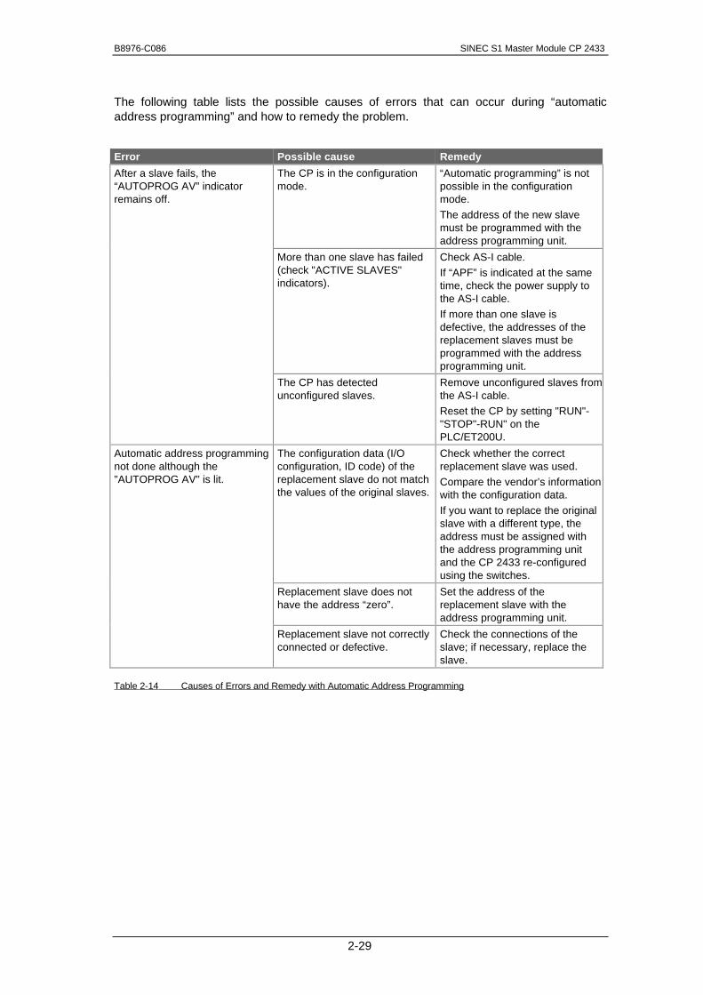
The following table lists the possible causes of errors that can occur during “automaticaddress programming” and how to remedy the problem.
Error Possible cause Remedy
After a slave fails, the“AUTOPROG AV” indicatorremains off.
The CP is in the configurationmode.
“Automatic programming” is notpossible in the configurationmode.
The address of the new slavemust be programmed with theaddress programming unit.
More than one slave has failed(check "ACTIVE SLAVES"indicators).
Check AS-I cable.
If “APF” is indicated at the sametime, check the power supply tothe AS-I cable.
If more than one slave isdefective, the addresses of thereplacement slaves must beprogrammed with the addressprogramming unit.
The CP has detectedunconfigured slaves.
Remove unconfigured slaves fromthe AS-I cable.
Reset the CP by setting "RUN"-"STOP"-RUN" on thePLC/ET200U.
Automatic address programmingnot done although the"AUTOPROG AV" is lit.
The configuration data (I/Oconfiguration, ID code) of thereplacement slave do not matchthe values of the original slaves.
Check whether the correctreplacement slave was used.
Compare the vendor’s informationwith the configuration data.
If you want to replace the originalslave with a different type, theaddress must be assigned withthe address programming unitand the CP 2433 re-configuredusing the switches.
Replacement slave does nothave the address “zero”.
Set the address of thereplacement slave with theaddress programming unit.
Replacement slave not correctlyconnected or defective.
Check the connections of theslave; if necessary, replace theslave.
Table 2-14 Causes of Errors and Remedy with Automatic Address Programming

SINEC S1 Master Module CP 2433 B8976-C086
2-30
2.2.6 Error Indicators of the CP 2433 in Standard Operation/Remedy if Errors Occur
The following table lists the possible causes of problems when operating the CP 2433 andhow to remedy the problem.
Error Possible cause Remedy
S1 POWER FAIL - indicator lit. The AS-I power supply unit is notconnected or is defective.
Check the connection of the AS-Ipower supply unit; if necessaryreplace the power supply unit.
Power requirements of the AS-Islave too high (total current greaterthan 2A).
Check the power requirements of theAS-I station. If necessary, supply theslaves with power externally.
FAULT LED lit continuously. CP 2433 defective Replace the CP 2433
FAULT LED lights up when themode selector is pressed.
You want to change to theprotected mode but a slave withaddress 0 exists.
Remove the slave with address 0from the AS-I cable or program anaddress with the addressing unit andthen run a PLC cold restart.
The mode selector was set to SETCONFIG in the protected mode.
Switch the CP to CHANGE MODEwith the mode selector and then toSET CONFIG.
CONFIG ERROR indicator lights up. The CP 2433 is not yet configured. Configure the CP with the modeselector on the front panel.
A configured slave has failed(evaluate the "ACTIVE SLAVES"indicator).
Replace the defective slave or if theslave is not required, re-configurethe CP 2433.
An unconfigured slave wasconnected to the AS-I cable.
Remove the slave or re-configure theCP 2433.
A slave has been connected whoseconfiguration data (I/Oconfiguration, ID code) do notmatch the value of the configuredslave.
Check whether an incorrect slavehas been connected. If necessary,re-configure the CP 2433.
CONFIG ERROR indicator flickers,meaning that a configured slavedrops out sporadically.
Bad contact. Check the connections of the AS-Islave.
Interference on the AS-I cable. Make sure the PLC is correctlygrounded and check along the AS-Icable.

B8976-C086 SINEC S1 Master Module CP 2433
2-31
Error indicators (continued)
Error Possible cause Remedy
CP does not switch from theconfiguration mode to the protectedmode.
The PLC is in the “RUN” mode. Switch the PLC to "STOP".
Selector not activated long enough. Make sure the selector is activatedfor 0.5 s.
A slave with the address 0 isconnected to the AS-I cable. TheCP 2433 cannot switch over to theprotected mode as long as thisslave exists.
Remove the slave with address 0.
CP does not switch from theprotected mode to the configurationmode.
The PLC is in the "RUN" mode. Switch the PL to "STOP".
Button not activated long enough. Make sure the selector is activatedfor 0.5 s.
Indicators 10+, 20+, 30+ light upsimultaneously and remain lit.
The CP has booted, but has notrecognized any slaves on the AS-Icable.
Connect the slaves to the AS-I cable.
Table 2-15 Error Indications in Standard Operation

SINEC S1 Master Module CP 2433 B8976-C086
2-32
2.3 Extended Operation
2.3.1 Overview of the Functions
Extended operation allows the master to be completely controlled by the user program.Access to inputs and outputs is the same as with I/O modules of the SIMATIC PLC. Incontrast to standard operation, with this type of operation, a special function block forcommunication with the SINEC S1 master CP must be included in the user program.
To allow a simple and convenient interface for the most common applications, a distinction ismade within this mode between a normal and an expert mode.
The normal mode provides an optimized interface to make installation, configuration andparameter assignment as straightforward as possible. Some of the jobs cover completesequences of AS-I commands and therefore reduce the load on the user program.
The expert mode provides access to the individual commands implemented on the AS-Imaster CP complying with the AS-I specification (refer also to the PICS in the appendix).
���� Extended operation is only possible with the S5-95U and S5-100U / CPU 103. AnS5-95U without integrated L2 interface (Order no. 6ES5095-8MA01) must be atleast version 2 to allow extended operation.

B8976-C086 SINEC S1 Master Module CP 2433
2-33
2.3.2 Programming the Interface
To supply the AS-I slaves with parameters, to supply the SINEC S1 communicationsprocessor CP 2433 with parameters and to configure it, or to read back parameters from theSINEC S1 communications processor during operation, you require a special function block(FB60) that is supplied with this manual.
Parameters and configuration data are exchanged between the CP and PLC using a workingdata block (working DB).
The data exchange (I/O data) between the function block and the CP is handled using theprocess image of the inputs and process image of the outputs as with a normal I/O module.
Fig. 2-10 Interface Elements for Extended Operation
For the address assignment in the PII/PIQ area, refer to the explanations in Section 2.1.6.
The FB has the following tasks during the PLC cycle:
±�Start-up control
When requested, the FB supplies the CP or the slaves with parameters andconfiguration data.
±�Checking the I/O data transfer
The FB checks and controls the I/O data transfer and the job transfer.
±�Processing jobs
The FB handles jobs issued by the user program using special function IDs.
Function block
Workingdata block
Start-up processing /Configuration
PII / PIQI/O dataexchange
I/O datato/fromCP
Job/diagnosticparameter datafrom/to CP
Jobs forchecking
Check

SINEC S1 Master Module CP 2433 B8976-C086
2-34
Calling the FB in the PLC Program
The function block must always be called once in OB1 at the start and at the end of a PLCcycle. This means that at the beginning of the cycle the PII area is updated and at the end ofa cycle any calls to the CP 2433 are entered in the PIQ area.
The following diagram illustrates how the user program, the function block FB60, the processimages PII and PIQ and the so-called working data block interact.
Fig. 2-11 How the Interface Functions in Extended Operation
The sequence illustrated in the diagram is explained below.
OB 21/22
OB 1FB 60
FB 60
PII/ PIQ
Userprogram
Read in PII
Output PIQ
Check functions
Check functions
Key: = cyclic execution
B8976-C086 SINEC S1 Master Module CP 2433
2-35
Receive end - update PII and pass on parameters
At the beginning of the cycle, the function block recognizes whether the data arriving from theCP 2433 are input data or response data to a job. The incoming data are saved in theworking DB.
If the CP 2433 sends the response to a job, the input data saved from the previous programcycle are copied into the process image of the inputs (PII) so that input data are once againavailable to the S5 user program (the user program does not “notice” that response dataarrived in this program cycle). The user then has direct access to the response data usingthe working DB.
Send end - output PIQ
The output data in the PIQ are transferred to the CP at the end of the cycle and from the CPto the AS-I slaves.
If a job has to be sent to the CP 2433, the function block waits until no output signal state haschanged in the PIQ during a program cycle. If there is no change in a cycle, the parameterassignment data are written from the working DB to the PIQ.
If no transfer of the job assignment data is possible due to continuously changing PIQ data,the transfer of the job is forced after a specified number of cycles despite changes in the PIQ(the number of cycles can be set with the FB parameter ZYK).
PIQ data are saved by the FB and if the parameter assignment data were transferred, thePIQ data are transferred in the following cycle.
Errors
If the CP 2433 does not exist at the address specified by the user for the function block(parameter BGAD), it cannot be recognized by the function block.
Start up OB
In the start up OBs (OB21, OB22), the user sets the start up ID in the parameter FKT (seeSection 2.3.4). The function block is, however, not called in the start up OBs. The functionBlock processes the start up routine only in the cyclic program.
Permanent storage of the FB
The function block can be stored permanently in the PLC memory in an EEPROM module ofthe PLC. It is also possible to re-name the block.
Transferring the working DB
���� Transfer of the working DB to the PLC or PG output of the working DB followedby re-transfer is not permitted when the PLC is in the RUN mode.
Interrupt and timer OBs
���� In the interrupt and time OBs, both access to the PII and the PIQ of the CP 2433and calling the function block are not permitted.

SINEC S1 Master Module CP 2433 B8976-C086
2-36
2.3.3 Description of the FB Job Processing
The function block is used both to set the mode of the CP and to transfer jobs to be executedonce. The following modes and jobs can be set by the FB parameters.
Start-up and cyclic mode: Configure configuration (with or without switching over to theprotected mode).
During the start-up routine of the FB, the CP is supplied with configuration data. The CP mustbe in the configuration mode (see Section 2.2.1).
The configuration data stored in the working DB are written to the CP and savedpermanently. The configuration data include the following:
±� Configured parameters
±� Configured I/O configuration
±� Configured ID codes
±� The list of configured slaves (LPS)
At the beginning of the transfer, the CP switches to the OFFLINE mode. At the end of thetransfer, the CP switches back to the ONLINE mode.
With an additional coding, the following distinction can be made at the end of a job:
1. The CP is switched to the protected mode when configuring is completed.
Communication is only with detected and configured AS-I slaves. The AS-I slavescan be supplied with the configured parameters.
2. The CP remains in the configuration mode when configuring is completed.
Communication is with all detected slaves (except slave address “0”).
Processing user jobs
±� Writing parameters
The parameters from the “parameter” field in the working DB are written to the CPand stored in the data image. The parameters that have changed are passed on bythe CP to the slaves.
±� Configuring parameters
The configured parameters of all the slaves are written from the working DB to theCP and entered in the configuration data of the CP.
The configured parameters are transferred to the slaves when the CP is booted(PLC power up, PLC STOP -> RUN).

B8976-C086 SINEC S1 Master Module CP 2433
2-37
±� Reading the configuration
The current I/O configuration, the current ID codes and the list of active slaves areread from the CP and entered in the fields configured I/Os, configured ID codes andLPS of the working DB.
These values (possibly after having been changed) can then be used to configurethe CP.
Command to CP (expert mode)
With this job, the data area “command to CP” of the working DB is written to the CP. Thisallows all the jobs of the AS-I specification to be triggered by the user application.
If jobs which provoke a response are issued, the response is entered in the commandresponse field of the working DB.

SINEC S1 Master Module CP 2433 B8976-C086
2-38
2.3.4 Interface of the Function Block FB60
The call interface of FB60 has the following structure:
:JU FB 60 FB 60
NAME :ASI:2433
DB : ASI:2433
BGAD : -- DB STAT --
FKT : -- BGAD
ZYK : -- FKT
STAT : -- ZYK
The function block can be called with direct or with indirect parameter assignment. With directparameter assignment, the actual operands specified in the block are valid for theparameters DB, BGAD, FKT and ZYK. With indirect parameter assignment, theseparameters must be entered in the working area of the working DB.
Description of the Block Parameters
Name Par Data Meaning Permitted values
DB D KF Number of the working datablock
KF = +x:
x = 0: indirect parameter assignment:
The parameters DB, BGAD and FKT are in thecalled data block from data word 1 to data word 5
DW1 = DB
DW2 = BGAD
DW3 = FKT
DW4 = ZYK
DW5 = STAT
10 <= x <= 255:
Direct parameter assignment:
x = Number of the working DB
BGAD D KF Module address (slot-dependent start address ofthe I/O area used by the CP)
KF = +x:
x ∈ [64, 80, 96, 112]
FKT I BY Function Flag byte(*)
ZYK D KF Maximum number of cycles KF = +x:
0 <= x <= 255
On completion of the specified number of PLCcycles, the transfer of the parameter data is forced,even if the user has changed the PIQ. If x=0, thetransfer is made immediately and without any old-new comparison of the PIQ.
STAT Q BY Status byte of the FB Flag or output byte(*)
Table 2-16 Input and Output Parameters of the Function Block FB60
(*) No scratchpad flags (FY200 to FY255) must be used

B8976-C086 SINEC S1 Master Module CP 2433
2-39
Assignment of the Input Parameter FKT:
±� IDs set during start-up. These settings must be made in the start-up OBs (OB21/22).
Bit 0: Start-up ID (must always be set in OB20/OB21)
Bit 1: Configuration - remain in configuration mode
Bit 2: Configuration - switch over to protected mode
Once the start-up has been processed, the input parameter FKT is overwritten with“0”.
±� Job IDs
Bit 3: Job: Write parameter
Bit 4: Job: Configure parameter
Bit 5: Job: Command to CP
Bit 6: Job: Read configuration
Bit 7: Reserved
The following rules apply to issuing jobs (job IDs):
Only one job can be selected. Once the job has been processed, the function blockoverwrites the input parameter FKT with “0”.
The only permitted settings for parameter FKT can be found in the following table:
Meaning FKT coding in HEXformat
Start-up ID set 01 H
Start-up ID set / create configuration - remain in configuration mode 03 H
Start-up ID set / create configuration - change to protected mode 05 H
Write parameter job 08 H
Configure parameter job 10 H
Command to CP job 20 H
Read configuration job 40 H
Table 2-17 Coding of the Parameter FKT

SINEC S1 Master Module CP 2433 B8976-C086
2-40
Bits of the output parameter STAT:
Bit 0: Job active
This bit is set by the function block as soon as the job is beingprocessed and while the CP is booting. The bit is reset when a newjob can be entered.
Bit 1: Error from FB or CP (error number in flag byte 255)
Bit 2...6: Reserved
Bit 7: CP is in the configuration mode
Using FB60 in the user program
The following diagram shows how the function block can be incorporated in the sequence ofthe control program.
Fig. 2-12 Flowchart of the User Progam
OB 21/22 (setsstart-up ID)
FB call at startof cycle
Evaluate error infofield of the CP
FB call at endof the cycle
S5user program
yes
Error no. in FY255
= CP error?
no
Reaction to error
Error bit inSTAT
set ?
no
yes

B8976-C086 SINEC S1 Master Module CP 2433
2-41
Error ID using FY255
If an error has occurred while the function block is being processed (STAT bit one set), theflag byte 255 contains more detailed information about the cause of the error.
If the function block signals a parameter assignment error, the cause can be derived from theerror number (e.g. data block does not exist or too short).
If an error is signaled by the CP during the processing of the job, this is signaled by a specificerror number in flag byte 255. The cause of the error can be found in the “error information ofthe CP” field in the working data block. After a CP error, the function block enters theavailable error information here.
If the function block is processed without errors, flag byte 255 has the value zero.
Error no. Meaning
0 No error
1 Illegal data block number
2 Data block does not exist
3 Data block too short
4 Illegal module address
5 Start-up not run through correctly
6 CP signaling error
7 Job invalid (content of FKT incorrect)
Points to note about error processing
The error bit indicates both error statuses in the AS-I system and when jobs are completedincorrectly.
An AS-I error status may exist over several cycles so that the error bit remains setconstantly. It is nevertheless possible that during this status (error = 1) a job can be executedand its correct execution can be detected. On completion of the job (the STAT bit “job active”changes from 1 to 0) the error bit indicates the result of job processing.
Fig. 2-13 Flowchart ‘Error Processing’
Case a)lasting error -job compelte without error
Error bit ->
Job active bit ->
Case b)lasting error -job complete with error
Error bit ->
Job active bit ->

SINEC S1 Master Module CP 2433 B8976-C086
2-42
2.3.5 Structure of the Working Data Block
The working data block is used as an area for transferring parameters and configuration databetween the PLC and the CP 2433.
The areas with the configuration data and the 3 lowest areas with the command field, thecommand response field and the error information of the CP are significant for theapplication.
The structure of the working data block can be seen in the following table:Bit 15 ... ... Bit 0
DW 0
...
Working area of the data block
DW 16
...
DW 24
...
DW 32 reserved Parameter slave 1 Parameter slave 2 Parameter slave 3
DW 33 Parameter slave 4 ...
...
DW 39 ... Parameter slave 31
DW 40 reserved Parameter slave 1 Parameter slave 2 Parameter slave 3
DW 41 Parameter slave 4 ...
... configuredDW 47 ... Parameter slave 31
DW 48 reserved I/O config. slave 1 I/O config. slave 2 I/O config. slave 3
DW 49 I/O config. slave 4 ...
...
DW 55 ... I/O config. slave 31
DW 56 reserved ID code slave 1 ID code slave 2 ID code slave 3
DW 57 ID code slave 4 ...
...
DW 63 ... ID code slave 31
DW 64 reserved reserved reserved reserved
DW 65 LPS slave 0-3
0 | 1 | 2 | 3
LPS slave 4-7
4 | 5 | 6 | 7DW 66 LPS slave 16-19 LPS slave 20-23
DW 67 reservedDW 68 reserved
DW 69 reservedDW 70 reservedDW 71 reserved
DW 72
...
DW 79
Command field : commands to the CP
DW 80
...
DW 87
Command response field
DW 88
...
DW 95
Error information of the CP
Fig. 2-14 Working Data Block
Configured parameter
Parameters
ConfiguredI/Os
ConfiguredID codes
LPS: configured slaves

B8976-C086 SINEC S1 Master Module CP 2433
2-43
2.3.6 Instructions for Configuring and Programming
2.3.6.1 How to Configure the CP 2433 with Function BlockWhen configuring the CP 2433 with the function block, the configuration data of the CP 2433are entered in the working data block. The CP 2433 recognizes the following configurationdata:
²� Configured parameters
²� Configured data (configured I/O configuration, configured ID code)
²� Configured slaves (LPS)
Follow the procedure assigned below when entering the configuration data.
�� Enter the configured parameters for the slaves in the appropriate field in the workingDB. Configured parameters are sent to the appropriate slaves after power on(default setting for the slaves). If your slaves (e.g. AS-I modules) do not evaluateparameters, assign the value “F” to the corresponding fields.
�� Enter the configuration data and the LPS in to the working DB. Here, there are twopossibilities:
1. First possibility - enter data according the vendor’s instructions
Take the I/O configuration and the ID code of the slaves connected to the AS-I cablefrom the manufacturer’s technical data and enter the values in the working DB. Foreach slave required on the cable, enter a “1” in the LPS. Enter a “0” in the LPS forslaves that should not be detected on the cable.
2. Second possibility - read out data from the slaves
Set the CP 2433 to the configuration mode and start-up your AS-I network step bystep. If everything runs correctly, you can then issue the job “read configuration” bysetting bit 6 of the parameter “FKT” to “1”. The function block then reads in thecurrent slave configuration connected to the AS-I cable and enters this in the fieldsof the working DB (configured I/O configuration, configured ID code and LPS).
These values are now available for configuring the CP.
The configuration data in the working DB must be saved on the CP. To do this, follow thesteps outlined below:
�� Switch the CP to the configuration mode (selector on the module)
�� Assign the value “1” to bit 2 of the parameter FKT in the start-up OBs
�� Switch your PLC from “STOP” to “RUN”
When the PLC is started up, the configuration data are now saved automatically on the CP.Following this, the CP switches to the protected mode.
If you set bit 1 instead of bit 2 in the FKT parameter, the CP remains in the configurationmode after saving the configuration data, i.e. it does not switch to the protected mode.

SINEC S1 Master Module CP 2433 B8976-C086
2-44
2.3.6.2 Automatic Configuration when a CP 2433 is ReplacedIf you assign “1” to bit 2 in the “FKT” parameter in the start-up OBs, a replacement CP 2433is automatically configured. Follow the steps outlined below:
�� Switch the CP 2433 to the configuration mode (as supplied)
�� Switch your PLC from “STOP” to “RUN”. The CP 2433 is then configured automaticallyby the function block. Following this, your user program continues to run completelynormally.
2.3.6.3 Check List for Programming the CP 2433 with Function Block�� Set bit 0 of the FKT parameter (start-up ID) to “1”, in the start-up OBs (OB21/22). If you
want a replacement CP 2433 to be configured automatically when the PLC starts-up,you should also set bit 2 of the start-up ID to “1”.
�� Make sure that the CP has been completely booted by checking bit 0 of the parameterSTAT for “0”. Only start your program when the CP is completely booted.
�� Address the inputs and outputs of the slaves as usual (see also the description of thestandard mode).
Example: CP start address 80 (corresponds to slot 2+3):
Address bit 0 of slave 1 as an input I80.0Address bit 2 of slave 2 as an output Q81.6
�� Scan the error bit of the function block cyclically (bit 1 in the “STAT” parameter). If anerror occurs, the function block enters an error ID in the working data block (fromDW88 onwards). This provides more detailed information about the cause of the error(see Section 2.3.9).
�� If required, send jobs from your user program via the function block to the CP. The typeof job is determined by the bit set in the “FKT” parameter (e.g. bit 3 for “writeparameter”). By evaluating the bit “job active” (bit 0) and the error bit (bit 1) in the“STAT” parameter you can check whether a job was executed correctly.
����� Supplying the parameter FKT directly using the PG test function “force variable”
is not permitted.
���� The example program on the diskettes supplied with this manual containsseveral examples for triggering and processing jobs.

B8976-C086 SINEC S1 Master Module CP 2433
2-45
2.3.7 Job: Write Parameters
The “write parameters” job allows you to make a simple parameter change for the slavesconnected to the AS-I cable.
The job follows the sequence as shown below:
±� First, the required parameters are entered in the working DB (DW40 to 47)
±� Following this, the “write parameter’s” job is triggered by setting bit 3 in FKT. The CPthen compares the parameters currently stored on the slaves with the values in thedata block to establish which parameters have changed. The slaves for whichparameters have changed are then assigned the new parameters by the CP.
±� By evaluating the bit “job active” and the error bit in the STAT parameter, you cancheck whether the job was correctly processed or not.
2.3.7.1 Job: Configure Parameters
With the “configure parameters” job, the configured parameters of all slaves are savedsimultaneously on the CP.
The sequence of the job is as below:
±� The configured parameters of all slaves are entered in the working DB (DW 32 to 39)
±� The “configure parameters” job is triggered by setting bit 4 in FKT. The CP then savesthe configured parameters that were entered in the data block. These parameters aretransferred to the slaves automatically during a cold restart.
±� By evaluating the “job active” bit and the error bit you can determine whether or not thejob was correctly executed.
�
���� The example program on the diskettes supplied with this manual containsseveral examples for triggering and processing jobs.

SINEC S1 Master Module CP 2433 B8976-C086
2-46
2.3.8 Description of the “Command to CP” Jobs
This section describes the command calls. These are the calls triggered in the function blockby the FKT parameter “bit 5”.
To transfer parameters, the command field in the working DB is used. To return parametersand messages, the command response field in the working DB is used. The entries in thefields are explained below.
Note on the representation in the command field of the working DB:
Relevant fields are shown on a white background; irrelevant fields are gray.
Note on the representation in the command response field of the working DB:
Relevant fields are shown on a white background; irrelevant fields are gray.
How you use the jobs can be found in the individual descriptions of the jobs, the descriptionsin Section 1.5 of the manual ’SINEC S1/AS-I Introduction an Basic Information’, the PICSappendix and the detailed explanations in /1/.
Fields to be completed
Return fields
Reserved or pre-assignedfields
Irrelevant fields
B8976-C086 SINEC S1 Master Module CP 2433
2-47
The commands that can be executed can be seen in the following table:
Name / Section Parameter Return Coding:
Set_Permanent_Parameter / 2.3.8.1 Slave address,Parameter
0 0 H
Get_Permanent_Parameter / 2.3.8.2 Slave address Parameter 0 1 H
Write_Parameter / 2.3.8.3 Slave address,Parameter
Return value (Echo) 0 2 H
Read_Parameter / 2.3.8.4 Slave address Parameter value 0 3 H
Store_Actual_Parameter / 2.3.8.5 None 0 4 H
Set_Permanent_Configuration / 2.3.8.6 Slave address,Configuration
0 5 H
Get_Permanent_Configuration /2.3.8.7
Slave address Configured data 0 6 H
Store_Actual_Configuration / 2.3.8.8 None 0 7 H
Read Actual Configuration / 2.3.8.9 Slave address Actual configuration data 0 8 H
Set_LPS / 2.3.8.10 LPS 0 9 H
Set_Offline_Mode / 2.3.8.11 Mode 0 A H
Set_Autoprogramming / 2.3.8.12 Mode 0 B H
Set_Operation_Mode / 2.3.8.13 Mode 0 C H
Change_Slave_Address / 2.3.8.14 Address 1,Address 2
Input data 0 D H
Read Slave Status / 2.3.8.15 Slave address Error record of the slave 0 F H
Read Lists and Flags / 2.3.8.16 None LDS,LAS,LPS,flags 1 0 H
Read List of ID Codes / 2.3.8.17 None ID codes 1 1 H
Read List of I/O Configurations /2.3.8.18
None I/O configurations 1 2 H
Read Parameter Echo List / 2.3.8.19 None Parameter echo list 1 3 H
Read Version Number / 2.3.8.20 None Version string 1 4 H
Slave Diagnostics / 2.3.8.21 Slave address Error counter of the slave 1 5 H
Read and Delete Slave Status /2.3.8.22
Slave address Error record of the slave 1 6 H
Read Slave ID / 2.3.8.23 Slave address ID Code 1 7 H
Read Slave I/O / 2.3.8.24 Slave address I/O configuration 1 8 H
Table 2-18 Overview of Command Jobs

SINEC S1 Master Module CP 2433 B8976-C086
2-48
2.3.8.1 Set_Permanent_Parameter
Meaning
With this call, a parameter value for the specified slave is transferred to the CP 2433. Thevalue is entered as a configured value in the configuration data.
The parameter is not transferred to the slave by the CP 2433. Only after a cold restart orwarm restart on the PLC is the parameter value transferred when the slave is activated.
���� The “configured parameter” field of the working DB is unchanged by this call.
Structure in the command field
Bit 15 Bit 12 Bit 11 Bit 8 Bit 7 Bit 4 Bit 3 Bit 0
DW 72 0 H 0 H
DW 73 Slave address 0 Parameter
DW 79

B8976-C086 SINEC S1 Master Module CP 2433
2-49
2.3.8.2 Get_Permanent_Parameter
Meaning
With this call, a parameter value in the EEPROM of the CP 2433 is read.
Structure in the command field
Bit 15 Bit 12 Bit 11 Bit 8 Bit 7 Bit 4 Bit 3 Bit 0
DW 72 0 H 1 H
DW 73 Slave address
DW 79
Structure in the command response field
Bit 15 Bit 12 Bit 11 Bit 8 Bit 7 Bit 4 Bit 3 Bit 0
DW 80
DW 81 0 H Parameter
DW 87

SINEC S1 Master Module CP 2433 B8976-C086
2-50
2.3.8.3 Write_Parameter
Meaning
With this call, a parameter value is transferred and is sent directly via the AS-I bus to theaddressed slave. The parameter is stored in temporary storage.
In the response, the slave returns the current parameter values that can deviate from thecurrently written values according to the AS-I master specification (/2/). These data areentered in the parameter echo.
Structure in the command field
Bit 15 Bit 12 Bit 11 Bit 8 Bit 7 Bit 4 Bit 3 Bit 0
DW 72 0 H 2 H
DW 73 Slave address 0 H Parameter
DW 79
Structure in the command response field
Bit 15 Bit 12 Bit 11 Bit 8 Bit 7 Bit 4 Bit 3 Bit 0
DW 80
DW 81 0 Parameter echo
DW 87

B8976-C086 SINEC S1 Master Module CP 2433
2-51
2.3.8.4 Read_Parameter
Meaning
With this call, the current parameter value (actual parameter) is returned.
Structure in the command field
Bit 15 Bit 12 Bit 11 Bit 8 Bit 7 Bit 4 Bit 3 Bit 0
DW 72 0 H 3 H
DW 73 Slave address
DW 79
Structure in the command response field
Bit 15 Bit 12 Bit 11 Bit 8 Bit 7 Bit 4 Bit 3 Bit 0
DW 80
DW 81 0 H Parameter
DW 87

SINEC S1 Master Module CP 2433 B8976-C086
2-52
2.3.8.5 Store_Actual_Parameters
Meaning
With this call, the configured parameters are overwritten by the actual parameters, i.e. theparameters are configured.
Structure in the command field
Bit 15 Bit 12 Bit 11 Bit 8 Bit 7 Bit 4 Bit 3 Bit 0
DW 72 0 H 4 H
DW 73
DW 79

B8976-C086 SINEC S1 Master Module CP 2433
2-53
2.3.8.6 Set_Permanent_Configuration
Meaning
With this call, the I/O configuration data and the ID code for the address AS-I slave areconfigured. The data are stored permanently on the AS-I master module.
���� When executing this command, the CP changes to the offline phase and thenswitches to the normal mode (cold restart on the CP).
Structure in the command field
Bit 15 Bit 12 Bit 11 Bit 8 Bit 7 Bit 4 Bit 3 Bit 0
DW 72 0 H 5 H
DW 73 Slave address ID code I/O configuration
DW 79

SINEC S1 Master Module CP 2433 B8976-C086
2-54
2.3.8.7 Get_Permanent_Configuration
Meaning
With this call, the desired configuration data stored in the EEPROM (i.e. configuration dataand the ID codes) of an addressed slave are returned.
Structure in the command field
Bit 15 Bit 12 Bit 11 Bit 8 Bit 7 Bit 4 Bit 3 Bit 0
DW 72 0 H 6 H
DW 73 Slave address
DW 79
Structure in the command response field
Bit 15 Bit 12 Bit 11 Bit 8 Bit 7 Bit 4 Bit 3 Bit 0
DW 80
ID code I/O configuration
DW 87

B8976-C086 SINEC S1 Master Module CP 2433
2-55
2.3.8.8 Store_Actual_Configuration
Meaning
With this call, the actual I/O configuration data and actual ID codes detected on the AS-I arestored permanently in the EEPROM. The list of active slaves (LAS) is stored permanently aslist of configured slaves (LPS).
���� When executing this command, the CP changes to the offline phase and thenswitches to the normal mode (cold restart on the CP).
In protected mode this call will not be executed.
Structure in the command field
Bit 15 Bit 12 Bit 11 Bit 8 Bit 7 Bit 4 Bit 3 Bit 0
DW 72 0 7
DW 73
DW 79

SINEC S1 Master Module CP 2433 B8976-C086
2-56
2.3.8.9 Read actual configuration data
With this call, the actual I/O configuration data and actual ID codes are of an addressed slavedetected on the AS-I are returned.
Structure in the command field
Bit 15 Bit 12 Bit 11 Bit 8 Bit 7 Bit 4 Bit 3 Bit 0
DW 72 0 H 8 H
DW 73 Slave address
DW 79
Structure in the command response field
Bit 15 Bit 12 Bit 11 Bit 8 Bit 7 Bit 4 Bit 3 Bit 0
DW 80
ID code I/O configuration
DW 87

B8976-C086 SINEC S1 Master Module CP 2433
2-57
2.3.8.10 Set_LPS
Meaning
With this call, the list of configured slaves is transferred for permanent storage in theEEPROM.
���� When executing this command, the CP changes to the offline phase and thenswitches to the normal mode (cold restart on the CP).
In protected mode this call will not be executed.
Structure in the command field
Bit 15 Bit 12 Bit 11 Bit 8 Bit 7 Bit 4 Bit 3 Bit 0
DW 72 0 H 9 H
DW 73 LPS slave 0..3
0 | 1 | 2 | 3
LPS slave 4..7
4 | 5 | 6 | 7
LPS slave 8..11
8 | 9 | 10 | 11
LPS slave 12..15
12 | 13 | 14 | 15
LPS slave 16..19 LPS slave 20..23 LPS slave 24..27 LPS slave 28..31
DW 79

SINEC S1 Master Module CP 2433 B8976-C086
2-58
2.3.8.11 Set_Offline_Mode
Meaning
This call switches between the online and offline mode.
The OFFLINE bit is not permanently stored, i.e. during the startup/restart the bit is set toONLINE again.
In the OFFLINE mode, the CP only processes jobs from the user. There is no cyclic dataexchange.
The online mode is the normal situation with the AS-I master. Here, the following jobs areprocessed cyclically:
• During the data exchange phase, the fields of the output data are transferred tothe slave outputs for all slaves in the LAS. The addressed slaves transfer thevalues of the slave inputs to the master when the transfer was free of errors.
• This is followed by the inclusion phase in which there is a search for the slavesconnected to the AS-I and newly added slaves are entered in the LDS or LAS.
• In the management phase, jobs from the user such as writing parameters areexecuted.
Structure in the command field
Bit 15 Bit 12 Bit 11 Bit 8 Bit 7 Bit 4 Bit 3 Bit 0
DW 72 0 H A H
DW 73 0 H Mode(0=online 1=offline)
DW 79

B8976-C086 SINEC S1 Master Module CP 2433
2-59
2.3.8.12 Select Autoprogramming
Meaning
With this call, the automatic address programming function can be enabled or disabled.
The autoprogramming bit is not stored permanently.
Structure in the command field
Bit 15 Bit 12 Bit 11 Bit 8 Bit 7 Bit 4 Bit 3 Bit 0
DW 72 0 H B H
DW 73 0 H Mode(1=autoprog allowed
0=autoprogdisabled)
DW 79
���� The change of the bit ‘AUTOADDRESS_ENABLE’ from 1 to 0 works immediately,the change from 0 to 1 only after changing the CP 2433 to OFFLINE!

SINEC S1 Master Module CP 2433 B8976-C086
2-60
2.3.8.13 Set_Operation_Mode
With this call, you can select between the configuration mode and the protected mode.
In the protected mode , only slaves marked in the LPS and whose desired and actualconfiguration match are activated, i.e. if the I/O configuration and the identification codes ofthe slaves in the LDS are identical to those of the configured values.
In the configuration mode , all detected slaves (except slave address “0”) are activated. Thisalso applies to slaves for which there is a difference between the desired and actualconfiguration. The OPERATION MODE bit is saved permanently in the EEPROM, i.e. it isretained following a start-up/warm restart.
When changing from the configuration mode to the protected mode, the CP is restarted(transition to the offline phase followed by switch-over to the online mode).
If the address 0 is entered in the LDS for a slave, the CP cannot switch from theconfiguration mode to the protected mode.
Structure in the command field
Bit 15 Bit 12 Bit 11 Bit 8 Bit 7 Bit 4 Bit 3 Bit 0
DW 72 0 H C H
DW 73 0 H Mode(0=protected mode
1=configurationmode)
DW 79
B8976-C086 SINEC S1 Master Module CP 2433
2-61
2.3.8.14 Change_Slave_Address
Meaning
With this call, the slave address can be changed.
This call is mainly used to add a new AS-I slave with the default address 0 to the SINEC S1system. In this case the address is changed from the old slave address (0) to the new slaveaddress.
This change can only be made when the following conditions are fulfilled.
1. A slave with the old address exists.
2. If the old slave address is not equal to 0, then a slave with address 0 cannot beconnected at the same time.
3. The new slave address must have a valid value.
4. There must be no slave with the new slave address.
Note: When changing the slave address, the slave is not reset, i.e. data are retained untilnew data arrive for the new address.
Structure in the command field
Bit 15 Bit 12 Bit 11 Bit 8 Bit 7 Bit 4 Bit 3 Bit 0
DW 72 0 H D H
DW 73 Old slave address New slave address
DW 79

SINEC S1 Master Module CP 2433 B8976-C086
2-62
2.3.8.15 Read Slave Status
Meaning
With this call, the status register of the addressed slave can be read out. The flags of thestatus register have the following significance:
S0 “Address volatile”This flag is set- when the internal slave routine for permanent storage of the slaveaddress is active. This can take up to 15 ms and must not be interruptedby a further addressing call.- when the internal slave address comparison recognizes that the storedaddress is not the same as the entry in the address register.
S1 “Parity error detected”This flag is set when the slave has recognized a parity error in a receivedframe since the last “read and delete status” job.
S2 “End bit error detected”This flag is set when the slave has recognized an end bit error in areceived frame since the last “read and delete status” job.
S3 “Read error non-volatile memory”This flag is set when a read error has occurred when reading the non-volatile memory.
Structure in the command field
Bit 15 Bit 12 Bit 11 Bit 8 Bit 7 Bit 4 Bit 3 Bit 0
DW 72 0 H F H
DW 73 Slave address
DW 79
Structure in the command response field
Bit 15 Bit 12 Bit 11 Bit 8 Bit 7 Bit 4 Bit 3 Bit 0
DW 80
0 Slave status
S3 | S2 | S1 | S0
DW 87
B8976-C086 SINEC S1 Master Module CP 2433
2-63
2.3.8.16 Read Lists and Flags (Get_LPS, Get_LAS, Get_LDS, Get_Flags)
Meaning
With this call, the following entries are read out of the AS-I master CP:
• the list of configured slaves
• the list of active slaves LAS
• the list of detected slaves LDS
• the flags according to the AS-I specification
Structure in the command field
Bit 15 Bit 12 Bit 11 Bit 8 Bit 7 Bit 4 Bit 3 Bit 0
DW 72 1 H 0 H
DW 73
DW 79
Structure in the command response field
Bit 15 Bit 12 Bit 11 Bit 8 Bit 7 Bit 4 Bit 3 Bit 0
DW 80
DW 81 LAS slave 0..3 LAS slave 4..7 LAS slave 8..11 LAS slave 12..15
LAS slave 16..19 LAS slave 20..23 LAS slave 24..27 LAS slave 28..31
LDS slave 0..3 LDS slave 4..7 LDS slave 8..11 LDS slave 12..15
LDS slave 16..19 LDS slave 20..23 LDS slave 24..27 LDS slave 28..31
LPS slave 0..3 LPS slave 4..7 LPS slave 8..11 LPS slave 12..15
LPS slave 16..19 LPS slave 20..23 LPS slave 24..27 LPS slave 28..31
DW 87 Flag1 Flag2
Flag 1:
Name Bit number
OFFLINE_READY 0
APF 1
NORMAL_MODE 2
CONFIG_MODE 3
AUTO_ADDR_AVAIL 4
AUTO_ADDR_ASSIGN 5
LES_0 6
CONFIG_OK 7
Name Bit number
Flag 2:
OFFLINE 0
RESERVED 1
EEPROM_OK 2
AUTO_ADDR_ENABLE 3
RESERVED 4
RESERVED 5
RESERVED 6
RESERVED 7

SINEC S1 Master Module CP 2433 B8976-C086
2-64
Meaning of the flags
OFFLINE_READY The flag is set when the offline phase is active.
APF This flag is set when the voltage on the AS-I cable is too low.
NORMAL_MODE This flag is set when the CP is in the normal mode.
OPERATION_MODE The flag is set in the configuration mode and reset in the protectedmode.
AUTO_ADDR_AVAIL This flag is set when automatic address programming is enabled(i.e. exactly one slave has failed).
AUTO_ADDR_ASSIGN This flag is set when automatic address programming is possible(i.e. AUTO_ADDR_ENABLE=1 and no ‘wrong’ slave is / wasconnected to the AS-I cable).
LES_0 This flag is set when a slave exists with address 0.
CONFIG_OK This flag is set when the desired (configured) and actualconfiguration match.
OFFLINE This flag is set when the CP is to change to the OFFLINE mode oris already in this mode.
EEPROM_OK This flag is set when the test of the internal EEPROM did not detectany errors.
AUTO_ADDR_ENABLE This flag is set when automatic address programming is enabled bythe user (set by HTB call).

B8976-C086 SINEC S1 Master Module CP 2433
2-65
2.3.8.17 Read List of ID Codes
Meaning
With this job, the ID code of the AS-I slave is read. The ID code along with the I/Oconfiguration is used to identify a slave uniquely.
The ID code is programmed once when the slave is manufactured and cannot be changed.
Structure in the command field
Bit 15 Bit 12 Bit 11 Bit 8 Bit 7 Bit 4 Bit 3 Bit 0
DW 72 1 H 1 H
DW 73
DW 79
Structure in the command response field
Bit 15 Bit 12 Bit 11 Bit 8 Bit 7 Bit 4 Bit 3 Bit 0
DW 80 ID code slave 1 ID code slave 2 ID code slave 3
DW 81 ID code slave 4 ID code slave 5 ID code slave 6 ID code slave 7
ID code slave 8 ID code slave 9 ID code slave 10 ID code slave 11
ID code slave 12 ID code slave 13 ID code slave 14 ID code slave 15
ID code slave 16 ID code slave 17 ID code slave 18 ID code slave 19
ID code slave 20 ID code slave 21 ID code slave 22 ID code slave 23
ID code slave 24 ID code slave 25 ID code slave 26 ID code slave 27
DW 87 ID code slave 28 ID code slave 29 ID code slave 30 ID code slave 31

SINEC S1 Master Module CP 2433 B8976-C086
2-66
2.3.8.18 Read List of I/O Configurations
Meaning
With this call, the I/O configuration set on the slaves can be read. The I/O configuration alongwith the ID code is used to identify a slave uniquely.The coding of the I/O configuration can be found in the manufacturer’s documentation for theAS-I slave.
Structure in the command field
Bit 15 Bit 12 Bit 11 Bit 8 Bit 7 Bit 4 Bit 3 Bit 0
DW 72 1 H 2 H
DW 73
DW 79
Structure in the command response field
Bit 15 Bit 12 Bit 11 Bit 8 Bit 7 Bit 4 Bit 3 Bit 0
DW 80 I/O conf. slave 1 I/O conf. slave 2 I/O conf. slave 3
DW 81 I/O conf. slave 4 I/O conf. slave 5 I/O conf. slave 6 I/O conf. slave 7
I/O conf. slave 8 I/O conf. slave 9 I/O conf. slave 10 I/O conf. slave 11
I/O conf. slave 12 I/O conf. slave 13 I/O conf. slave 14 I/O conf. slave 15
I/O conf. slave 16 I/O conf. slave 17 I/O conf. slave 18 I/O conf. slave 19
I/O conf. slave 20 I/O conf. slave 21 I/O conf. slave 22 I/O conf. slave 23
I/O conf. slave 24 I/O conf. slave 25 I/O conf. slave 26 I/O conf. slave 27
DW 87 I/O conf. slave 28 I/O conf. slave 29 I/O conf. slave 30 I/O conf. slave 31

B8976-C086 SINEC S1 Master Module CP 2433
2-67
2.3.8.19 Read Parameter Echo List
Meaning
This call takes into account possible future extensions of the AS-I function.
When the parameters are transferred to the slave, they return “echo values” as the response.With the call, read parameter echo list, the echo values of all slaves are read out.
Structure in the command field
Bit 15 Bit 12 Bit 11 Bit 8 Bit 7 Bit 4 Bit 3 Bit 0
DW 72 1 H 3 H
DW 73
DW 79
Structure in the command response field
Bit 15 Bit 12 Bit 11 Bit 8 Bit 7 Bit 4 Bit 3 Bit 0
DW 80 Par. echo slave 1 Par. echo slave 2 Par. echo slave 3
DW 81 Par. echo slave 4 Par. echo slave 5 Par. echo slave 6 Par. echo slave 7
Par. echo slave 8 Par. echo slave 9 Par. echo slave 10 Par. echo slave 11
Par. echo slave 12 Par. echo slave 13 Par. echo slave 14 Par. echo slave 15
Par. echo slave 16 Par. echo slave 17 Par. echo slave 18 Par. echo slave 19
Par. echo slave 20 Par. echo slave 21 Par. echo slave 22 Par. echo slave 23
Par. echo slave 24 Par. echo slave 25 Par. echo slave 26 Par. echo slave 27
DW 87 Par. echo slave 28 Par. echo slave 29 Par. echo slave 30 Par. echo slave 31

SINEC S1 Master Module CP 2433 B8976-C086
2-68
2.3.8.20 Read Version ID
Meaning
With this call, the version ID of the AS-I master software is read out.
Structure in the command field
Bit 15 Bit 12 Bit 11 Bit 8 Bit 7 Bit 4 Bit 3 Bit 0
DW 72 1 H 4 H
DW 73
DW 79
The reply of the CP contains the name and the firmware version number of the CP in theform shown below:
Structure in the command response field
Bit 15 Bit12
Bit 11 Bit 8 Bit 7 Bit 4 Bit 3 Bit 0
DW 80 KS: C
DW 81 KS: P 2
4 3
3 .
. V
x .
DW 86 KS: y y
DW 87 KS:
x.yy stands for the current version number.

B8976-C086 SINEC S1 Master Module CP 2433
2-69
2.3.8.21 Slave Diagnostics
Meaning
This command returns the number of AS-I errors that occurred in conjunction with a slave.With this call, the error counter is then deleted.
The value of the error counter is incremented in the following situations:
±�When a slave does not reply correctly during the data exchange phase despiterepeating the master frame (i.e. missing or incorrect slave frame).
±�With slaves that have not been activated, the error counter is incremented when a slavehas already been detected (i.e. it exists in the LDS) but then no longer correctly replies.
The error counter is incremented to a maximum value of 255 and then remains at this valueuntil deleted.
Structure in the command field
Bit 15 Bit 12 Bit 11 Bit 8 Bit 7 Bit 4 Bit 3 Bit 0
DW 72 1 H 5 H
DW 73 Slave address
DW 79
Structure in the command response field
Bit 15 Bit 12 Bit 11 Bit 8 Bit 7 Bit 4 Bit 3 Bit 0
DW 80
Slave error counter
DW 87
SINEC S1 Master Module CP 2433 B8976-C086
2-70
2.3.8.22 Read Slave Status and Delete
Meaning
With this call, the status of a slave is read out and at the same time the status register of theslave is deleted.The flags of the status register have the following meaning:
S0 “Address volatile”This flag is set- when the internal slave routine for permanent storage of the slaveaddress is active. This can take up to 15 ms and must not be interruptedby a further addressing call.- when the internal slave address comparison recognizes that the storedaddress is not the same as the entry in the address register.
S1 “Parity error detected”This flag is set when the slave has recognized a parity error in a receivedframe since the last “read and delete status” job.
S2 “End bit error detected”This flag is set when the slave has recognized an end bit error in areceived frame since the last “read and delete status” job.
S3 “Read error non-volatile memory”This flag is set when a read error has occurred when reading the non-volatile memory.
Structure in the command field
Bit 15 Bit 12 Bit 11 Bit 8 Bit 7 Bit 4 Bit 3 Bit 0
DW 72 1 H 6 H
DW 73 Slave address
DW 79
Structure in the command response field
Bit 15 Bit 12 Bit 11 Bit 8 Bit 7 Bit 4 Bit 3 Bit 0
DW 80
0 H Slave status
DW 87

B8976-C086 SINEC S1 Master Module CP 2433
2-71
2.3.8.23 Read Slave ID
Meaning
With this call, the ID code of a slave can be read out directly over the AS-I cable. The call isintended for diagnostic purposes and is not required in the normal master mode.
Structure in the command field
Bit 15 Bit 12 Bit 11 Bit 8 Bit 7 Bit 4 Bit 3 Bit 0
DW 72 1 H 7 H
DW 73 Slave address
DW 79
Structure in the command response field
Bit 15 Bit 12 Bit 11 Bit 8 Bit 7 Bit 4 Bit 3 Bit 0
DW 80
0 H Slave ID
DW 87

SINEC S1 Master Module CP 2433 B8976-C086
2-72
2.3.8.24 Read Slave I/O
Meaning
With this call, the I/O configuration of a slave can be read out directly over the AS-I cable.The call is intended for diagnostic purposes and is not required in the normal master mode.
Structure in the command field
Bit 15 Bit 12 Bit 11 Bit 8 Bit 7 Bit 4 Bit 3 Bit 0
DW 72 1 H 7 H
DW 73 Slave address
DW 79
Structure in the command response field
Bit 15 Bit 12 Bit 11 Bit 8 Bit 7 Bit 4 Bit 3 Bit 0
DW 80
0 H Slave I/O
DW 87

B8976-C086 SINEC S1 Master Module CP 2433
2-73
2.3.9 Error Processing / Assignment of the Error Numbers
Structure in the Error Information Field of the CP
Bit 15 Bit 12 Bit 11 Bit 8 Bit 7 Bit 4 Bit 3 Bit 0
DW 88 Error ID ID byte 1
DW 89 ID byte 2 ID byte 3
Disc. slave 0-3 Disc. slave 4-7 Disc. slave 8-11 Disc. slave 12-15
Disc. slave 16-19 Disc. slave 20-23 Disc. slave 24-27 Disc. slave 28-31
DW 95
²�The error ID has the following structure:
Bit 15..12 Bit 11 Bit 10 Bit 9 Bit 8
Status APF Configuration error Command error 0
Bit 11: APF error (=ASI power fail)
Bit 10: Configuration error (only indicated in the protected mode):
If a configuration error occurs, bytes 4-7 indicate the slaves for which the configureddata deviate from the actual configuration.
Bit 9: Command error
²�Byte 1-3: Contains information about incorrect commands:
Byte 1: Indicates which command was executed
Byte 2: Indicates which slave is affected (FFH=no particular slave)
Byte 3: Indicates the error type
²�Byte 4-7: List of slaves with configuration discrepancies
Each bit corresponds to exactly one slave.
Bit = 1 Means that the slave differs from the set configuration

SINEC S1 Master Module CP 2433 B8976-C086
2-74
Error types:
Long text Short text Decimal value
No error OK 0
Addressold wrong ADDR1_WRONG 1
Slave not in LAS NOT_IN_LAS 2
Addressnew wrong ADDR2_WRONG 3
Not allowed in CP status (e.g. offline) NOT_ALLOWED 5
Transferred list empty LIST_EMPTY 6
Slave 0 exists SLAVE_0_EXISTS 8
Slave with addressold not detected SND_ERROR 10
A slave with address 0 already exists SD0_ERROR 11
A slave with addressnew already exists SD2_ERROR 12
Error deleting the slave address DE_ERROR 13
Error setting the new slave address SE_ERROR 14
Address only stored temporarily AT_ERROR 15
Command not implemented NOT_IMPLEM 254
Unknown command UNKNOWN 255
Table 2-19 Error Types
���� If the error number 6 is entered in FY 255 (CP signals error) and the field “errorinformation of the CP” in the working DB has “0” entered, this can have twopossible causes:
1. When booting the CP 2433, an AS-I power fail was detected
2. When booting the CP 2433, there are no slaves.
The following error types (following the short text in Table 2-19) are now explained in detail.
ADDR1_WRONG
The specified address is incorrect. The address is either not in the range 0 to 31 or you haveattempted to configure parameters or data for slave 0 or to transfer parameters to slave 0.This is not permitted. Please check the selected slave address.
NOT_IN_LAS
The job was rejected because the selected slave was not in the LAS at the time when the jobshould have been processed. Please check whether the slave you have addressed existsand whether it is functioning correctly.

B8976-C086 SINEC S1 Master Module CP 2433
2-75
ADDR2_WRONG
The address transferred in the call is not valid. Only values from 0 to 31 (inclusive) can betransferred.
NOT_ALLOWED
The AS-I master call you have attempted is not permitted in the current CP status. Pleaseswitch to the operating mode or offline mode required for your job according to /1/.
LIST_EMPTY
The list transferred for configuring the slaves (LPS) is empty. Please select at least one slaveyou would like to configure.
SLAVE_0_EXISTS
It is not possible to switch to the protected mode if slave 0 exists. Please assign a validaddress to this slave.
DATA_WRONG
A parameter call had an illegal value (e.g. the parameter ‘Mode‘ of the call‘Set_Operation_Mode’ was not ‘0’ or ‘1’).
SND_ERROR
You have attempted to change the address of a non-existent slave. Please check theaddress information in the AS-I call.
SD0_ERROR
You have attempted to change the address of a slave although slave 0 exists. Assign a validaddress to this slave (note: an address change is always made using slave 0 (/1/)).
SD2_ERROR
You have attempted to assign an existing address to a slave. Please check the addressinformation in the AS-I call.
DE_ERROR
An error has occurred when deleting the address of the slave. Please check that the slave isfunctioning correctly.
SE_ERROR
An error has occurred setting the address of the slave. Please check that the slave isfunctioning correctly.
AT_ERROR
The slave you are addressing could not store the new address. Please check that the slave isfunctioning correctly.
NOT_IMPLEM / UNKNOWN
The command is not implemented or is unknown. You have specified an incorrect commandID with the call. Check the command ID in your working data block.
R

SINEC S1 Master Module CP 2433 B8976-C086
2-76

B8976-C086 PICS
A-1
A ASI Protocol Implementation Conformance Statement (PICS)
A.1 PICS für CP 2433
Vendor Siemens AG
Product Name CP 2433 - SINEC S1 master module for S5-90U, S5-95U, S5-100U and ET200U
Order Number 6GK1243-3SA00
Version 1
Master Profile M1 with function block, M0 without function block
Date 27.9.1994
List of Master Functions Available with Function Block
No. Function or Call to the Host Interface(symbolic representation)
M1 Comment / Function implemented by/ Section
1 Image, Status = Read_IDI() X By process image of the controller
(PII)
2 Status = Write_ODI(Image) X By process image of the controller
(PIQ)
3 Status = Set_Permanent_Parameter(Addr, Param) X Set_Permanent_Parameter / 2.3.8.1
4 Param, Status = Get_Permanent_Parameter(Addr) X Get_Permanent_Parameter / 2.3.8.2
5 Status, Param = Write_Parameter(Addr, Param) X Write Parameters / 2.3.7
Write_Parameter / 2.3.8.3
6 Status, Param = Read_Parameter(Addr) X Read_Parameter / 2.3.8.4
7 Status = Store_Actual_Parameters() X Store_Actual_Parameter / 2.3.8.5
8 Status = Set_Permanent_Configuration(Addr,Config)
X Set_Permanent_Configuration / 2.3.8.6
9 Status, Config =Get_Permanent_Configuration(Addr)
X Get_Permanent_Configuration / 2.3.8.7
10 Status = Store_Actual_Configuration() X Store_Actual_Configuration / 2.3.8.8This command also triggers a coldrestart on the CP.
11 Status, Config = Read_Actual_Configuration(Addr) X Read_Actual_Configuration / 2.3.8.9
12 Status = Set_LPS(List31) X Set_LPS / 2.3.8.10
13 Status, List31 = Get_LPS() X Read Lists and Flags 2.3.8.16

B8976-C086 PICS
A-2
14 Status, List31 = Get_LAS() X Read Lists and Flags / 2.3.8.16
15 Status, List32 = Get_LDS() X Read Lists and Flags / 2.3.8.16
16.0 Status = Get_Flags() X Read Lists and Flags / 2.3.8.16
16.1 Status, Flag = Get_Flag_Config_OK() X CP error bit, LED display
Read Lists and Flags / 2.3.8.16
16.2 Status, Flag = Get_Flag_LDS.0() X Read Lists and Flags / 2.3.8.16
16.3 Status, Flag = Get_Flag_Auto_Address_Assign() X Read Lists and Flags / 2.3.8.16
16.4 Status, Flag = Get_Flag_Auto_Prog_Available() X Read Lists and Flags / 2.3.8.16
16.5 Status, Flag = Get_Flag_Configuration_Active() X Read Lists and Flags / 2.3.8.16
16.6 Status, Flag =Get_Flag_Normal_Operation_Active()
X Read Lists and Flags / 2.3.8.16
16.7 Status, Flag = Get_Flag_APF() X CP error bit, LED display
Read Lists and Flags / 2.3.8.16
16.8 Status, Flag = Get_Flag_Offline_Ready() X Read Lists and Flags / 2.3.8.16
17 Status = Set_Operation_Mode(Mode) X Set_Operation_Mode / 2.3.8.13
18 Status = Set_Offline_Mode(Mode) X Set_Offline_Mode / 2.3.8.11
19 Status = Activate_Data_Exchange(Mode) - not implemented
20 Status = Change_Slave_Address(Addr1, Addr2) X Change_Slave_Address / 2.3.8.14

B8976-C086 PICS
A-3
No. Function or Call to the HostInterface (symbolic representation)
M1 Comment / Function implemented by /Section
21.1 Status, Resp =Cmd_Reset_ASI_Slave(Addr, RESET)
- not implemented
21.2 Status, Resp =Cmd_Read_IO_Configuration(Addr,CONF)
X Read slave I/O / 2.3.8.24
21.3 Status, Resp =Cmd_Read_Identification_Code(Addr,IDCOD)
X Read slave ID / 2.3.8.23
21.4 Status, Resp =Cmd_Read_Status(Addr, STAT)
X Read slave status / 2.3.8.15
21.5 Status, Resp =Cmd_Read_Reset_Status(Addr,STATRES)
X Read and slave status and delete / 2.3.8.22
List of Master Functions Available Without Function Block
No. Function or Call to the Host Interface (symbolicrepresentation)
M0 Comment / Function implementedby / Section
1 Image, Status = Read_IDI() X By process image of the controller
(PII)
2 Status = Write_ODI(Image) X By process image of the controller
(PIQ)
3 Status = Set_Permanent_Parameter(Addr, Param) - not implemented
4 Param, Status = Get_Permanent_Parameter(Addr) - not implemented
5 Status, GParam = Write_Parameter(Addr, Param) - not implemented
6 Status, Param = Read_Parameter(Addr) - not implemented
7 Status = Store_Actual_Parameters() - not implemented
8 Status = Set_Permanent_Configuration(Addr, Config) - not implemented
9 Status, Config = Get_Permanent_Configuration(Addr) - not implemented
10 Status = Store_Actual_Configuration() X Switch on front panel
11 Status, Config = Read_Actual_Configuration(Addr) - not implemented
12 Status = Set_LPS(List31) - not implemented
13 Status, List31 = Get_LPS() - not implemented
14 Status, List31 = Get_LAS() - not implemented
15 Status, List32 = Get_LDS() - not implemented
16.0 Status = Get_Flags() - not implemented

B8976-C086 PICS
A-4
16.1 Status, Flag = Get_Flag_Config_OK() X CP error bit, LED display on frontpanel
16.2 Status, Flag = Get_Flag_LDS.0() - not implemented
16.3 Status, Flag = Get_Flag_Auto_Address_Assign() - not implemented
16.4 Status, Flag = Get_Flag_Auto_Prog_Available() - not implemented
16.5 Status, Flag = Get_Flag_Configuration_Active() - not implemented
16.6 Status, Flag = Get_Flag_Normal_Operation_Active() - not implemented
16.7 Status, Flag = Get_Flag_APF() X CP error bit, LED display on frontpanel
16.8 Status, Flag = Get_Flag_Offline_Ready() - not implemented
17 Status = Set_Operation_Mode(Mode) X Switch on front panel of the CP
18 Status = Set_Offline_Mode(Mode) - not implemented
19 Status = Activate_Data_Exchange(Mode) - not implemented
20 Status = Change_Slave_Address(Addr1, Addr2) - not implemented
21.1 Status, Resp = Cmd_Reset_ASI_Slave(Addr, RESET) - not implemented
21.2 Status, Resp = Cmd_Read_IO_Configuration(Addr,CONF)
- not implemented
21.3 Status, Resp = Cmd_Read_Identification_Code(Addr,IDCOD)
- not implemented
21.4 Status, Resp = Cmd_Read_Status(Addr, STAT) - not implemented
21.5 Status, Resp = Cmd_Read_Reset_Status(Addr,STATRES)
- not implemented
Key to column 3
Character Meaning
X Function exists
- Function does not exist

B8976-C086 Abbreviations / Terms
B-1
B Abbreviations / TermsAS-I Actuator-Sensor-InterfaceAS-I library Library with which user programs can communicate with the AS-I
driver.AS-I driver Driver that makes the functions of the CP 2413 available to user
programsAPF ASI power fail. Flag or LED that indicates that the voltage on the
AS-I-line is too low. (e.g. failure of the AS-I power supply)CP Communications processor: module for installation in computers
and programmable logic controllers.CP 2433 Communications processor for SIMATIC S5 and ET 200 on SINEC
S1.CP 1413 Communications processor for PCs and PGs on SINEC H1CP 2413 Communications processor for PCs and PGs on SINEC S1CP 5412 Communications processor for PCs and PGs on SINEC L2FW Firmware, here software running on the CP 2413LAS List of activated slavesLDS List of detected slavesLPS List of configured (permanent) slavesPG Programmer (programming unit)PLC Programmable logic controller; e.g. SIMATIC S5 PLCSINEC 'Siemens Network Architecture for Automation and Engineering',
Range of Siemens products for industrial communication.�

B8976-C086 Abbreviations / Terms
B-2
B8976-C086 Further Reading
C-1
C Further Reading
/1/ ASI Das Aktuator-Sensor-Interface für die Automation
Werner Kriesel, O.W. Madelung, Carl Hanser Verlag München Wien 1994
(only available in German)
/2/ ASI Complete Specification
can be ordered from the ASI association e.V.
Address : ASI-Verein e.V.Auf den Broich 4A51519 OdenthalGermany
Tel.: 02174 / 40756Fax.:02174 / 41571
(The AS-I technology is promoted by the ASI association e.V.)
/3/ SINEC Industrial Communications Networks
Catalog IK 10 1994U

B8976-C086 Further Reading
C-2

B8976-C086 Notes on CE Marking
D-1
D Notes on the CE Marking of SINEC Products
Product Name CP 2433 6GK1 243-0SA00
EC EMC Directive89/336/EEC
The SINEC products listed above meet the requirements of the EC Directice89/336/EEC “Electromagnetic Compatibility“
The EC conformity certificates are kept for the authorities responsibleaccording to the EC directives listed above at the following address:
Siemens AktiengesellschaftBereich AutomatisierungstechnikIndustrielle Kommunikation (AUT 93)Postfach 4848D-90327 NürnbergFederal Republic of Germany
Area of ApplicationEMC
The product meets the following requirements:
Area of application Requirements
Emission Immunity
Industry EN 50081-2 : 1993 EN 50082-2 : 1995
The product can also be used in the residential environment (residential,commercial and light industry).
Area of application Requirements
Emission Immunity
Residential Individual approval EN 50082-1 : 1992
You must acquire the individual approval from the respective nationalauthority or testing body.
InstallationGuidelines
This product meet the requirements providing you adhere to the installationguidelines
1. Manual of CP 2433 Master Module;2. System Manual AG S5-90U, S5-95U, S5-100U, Manual for ET200U
Working with theProduct
To protect the product from electrostatic discharge, personnel must firstneutralize any charges on their person before touching the modules.
Notes for theManufacturers ofMachines
The product is not a machine in the sense of the EU directive. There istherefore no conformity certificate for the EU directive 89/392 for machines. Ifthe product is part of the electrical equipment of a machine, the manufacturerof the machine must include the product in the conformity certificateprocedure for the machine.

B8976-C086 Notes on CE Marking
D-2

KorrekturenCorrections
Für Druckschrift bzw. HandbuchFor instruction or manual
Titel/title
SIEMENS AGAUT 933Siemensallee 84
76187 KarlsruheFederal Republic of Germany
Firma/Dienststelle - Company/Department
Anschrift/Address
Vorschläge und/oder KorrekturenSuggestions/Corrections
Bestell-Nr./Order No.
Telefon/Telephone
Sollten Sie beim Lesen dieser Un-terlage auf Druckfehler gestoßensein, so bitten wir Sie, uns diese mit-zuteilen. Ebenso sind wir für Anre-gungen, Hinweise und Verbesse-rungsvorschläge dankbar.
Bitte die Bestell-Nr. der betreffen-den Druckschrift oder des Hand-buches oben eintragen!
Should you come across any printingerrors when reading this publication,we would ask you to inform us usingthis form. We would also welcomeany suggestions you may have forimprovement.
Please fill in the order no. of the af-fected document!
VorschlägeSuggetions
Absender/From - Name/Name
SINEC S1 Masterbau module 2433
6GK 1971-2SA01-0AA1

CorrectionsCorrecciones
Pour l’imprimé ou le manuelPara folleto o manual
Titre/titulo
N° de ref./N° de ped.
Société/Service - Empresa/Seccion
Adresse/Direction Téléphone/Téléphono
Propositions ou correctionsPropuestas y/o correcciones
Si, lors de la lecture de ce docu-ment, vous trouvez des fautes d’im-primerie, nous vous prions de nousen faiire part dans ce formulaire.Nous recevrons aussi avec recon-naissance vos suggestions, remarqu-es et propositions d’amélioration.
Indiquez s.v.p. le n° de référencede l’imprimé ou de manuel concer-ne !
Si encuentra Usted erratas de im-prenta, por favor, infórmenos utili-zando este formulario. Le rogamosque nos communique también lasreclamaciones, indicaciones, y propu-estas de mejoramiento.
Indique por favor el N° de pedidodel folleto o del manual respecti-vo!
SIEMENS AGAUT 933Siemensallee 84
76187 KarlsruheFederal Republic of Germany
Expediteur/Expeditor - Nom/Nombre y apelido
SINEC S1 Master module 2433
6GK 1971-2SA01-0AA1