siprotec 7sj531 numerical line and motor protection … · digsi or lsa/scada the positions of ......
TRANSCRIPT

SIPROTEC 7SJ531Numerical Line and Motor Protectionwith Control Functions
Protection Systems
Catalog LSA 2.1.9October 1997

Protection systemsPage
Features 2
Index of catalogs 28
Description 3 to 6
Feeder control diagrams 7 and 8
Functions 9 to 15
Typical applications 16 to 19
Technical data 20 to 23
Selection and ordering data 24
Connection diagram 25
Technical specification 27
Siemens LSA 2.1.9 ⋅ Oct. 1997 1
Siemens AG 1997
SIPROTEC 7SJ531(Version V3.2)NumericalLine and Motor Protectionwith Control Functions
Catalog LSA 2.1.9 ⋅ October 1997
Dimension drawings
(in mm) 26
Supersedes: Catalog LSA 2.1.9 ⋅ 1997
Conditions of sale
and delivery 28

Features
Line protection
Overcurrent-time protec-tion, phase and earth-fault protection, eitherdefinite-time or inverse-time (IEC or ANSI)
Reverse interlocking Overload protection acc.
to IEC 255-8 Undervoltage and over-
voltage protection Automatic reclosure Sensitive earth-fault de-
tection Circuit-breaker failure
protection Directional overcurrent-
time protection Directional comparison
protection Unbalanced-load protec-
tion Fault locator Switch-onto-fault.
Motor protection
Overcurrent-timeprotection
Stator overload protec-tion with 2 time constants
Starting time monitoring(locked-rotor protection)
Start inhibit Unbalanced-load protec-
tion Undercurrentdetection.
Transformer protection
Overcurrent-time protec-tion
Overload protection(IEC 255-8)
Unbalanced-loadprotec-tion.
Control
1 switching device viathe integrated operatingpanel, 2 binary inputs,DIGSI or LSA/SCADA
The positions of up to 5switching elements areshown on the graphicdisplay
22 feeder control dia-grams for single and du-plicate busbars for adap-tation to the switchingbay
Local-remote switching.
2 Siemens LSA 2.1.9 ⋅ Oct. 1997
IEC
V<<, t ; V<, t
P>; Q>
I<
I2>>, t ; I2>, t
ϑ>, IEC 255-8
I>>
IE>>
I>>, t ; I>, t ; Ip
59
64
67
79
55
51
50
49
48
47
46
37
27
51BF
ANSI IEC
IE>>, t ; IE>, t ; IEp
CB I>, t
cos ϕ<
V>, t
V0>, t
IEE>>, t ; IEE>, t
Idir.>>, t ; Idir.>, t
auto-reclosure
start inhibit
trip circuit monitoring
ANSI
LSP2
009f
.eps
Monitoring
Operational measuredvaluesI, V, P, Q, Θ, f
Energy metering valuesWp, Wq
Threshold valuesP >, Q >, cos ϕ<
Timemeteringofoperatinghours.
Additional functions
Trip circuit monitoring Parameter set change-
over User-definable charac-
teristics for overcurrent-time protection, direc-tional overcurrent-timeprotection and direction-al earth-fault detection
Test OPEN and testOPEN-CLOSE cycle(Trip contact testing)
Fault recording8 fault eventprotocols8 fault oscillographicrecordings.
Communication
IEC 870-5-103 interfaceto LSA/SCADA
PC with DIGSI viamodem.
Hardware
Auxiliary voltages24/48/60/110/125/220/250 V DC
Local control Graphic display Analog inputs
5 current transformers3 voltage transformers
Digital inputs/outputs11binary inputs5alarmrelays4commandrelays.
50N
51N
67N
phase sequencemonitoringstarting timemonitoring
Fig. 17SJ531 numerical overcurrent-timeprotection (flush mounting housing)
SIPROTEC 7SJ531 (Version V3.2)Numerical Line and Motor Protection with Control Functions

Fig. 2Front view(surface mounting housing)
Rear view(flush mounting housing)
LSP2
010f
.eps
LSP2
011f
.eps
Siemens LSA 2.1.9 ⋅ Oct. 1997 3
Description
Application
The 7SJ531 is a numericalcombined control, protectionand monitoring device. As aline protection device it is usedfor medium-voltage networkswith low-resistance earthing,solid earth (grounded), isolatedor compensated starpoint. It isequally suitable for radial net-works fed from one side or foropen rings, as well as forlines fed from two sides or forclosed rings.As a motor protection relay the7SJ531 is suitable for asyn-chronous machines of all sizesand as back-up protection it iswell suited for equipmentrequiring differential protectionsuch as lines, transformers orgenerators.The integrated control functionsallow control of the switchingdevice via the integrated operat-ing panel, 2 binary inputs,DIGSI or LSA/SCADA. Varioustypes of switchgear with sin-gle and duplicate busbar whichcontain a controllable switchingdevice, are supported.
Design
Within its compact design, theunit contains:• All components for analog
value acquisition and nume-rical evaluation
• Integrated keypad and gra-phic display with feeder con-trol diagram
• Indication and command out-puts
• Binary inputs• Serial interfaces for parame-
terization and connection tosubstation control and pro-tection
• Auxiliary voltage converter.The device can be suppliedwith two different housings.The housing for panel flush orcubicle mounting has rearsideconnection terminals. Thehousing designed for panel sur-face mounting is provided withtwo-tier terminals accessiblefrom above and below.
Constant self-monitoring
Hardware and software areconstantly monitored and irreg-ularities immediately detectedand signalled. This ensures avery high degree of safety, re-liability and availability.
Improved measurementtechnique
With the use of a powerful mi-cro-processor and numericalanalog value conditioning andprocessing, the effect of high-frequency transients and tran-sient DC components arelargely suppressed.The definite-time charac-teristics measurement evalua-tes the fundamental compo-nent of the current (from aFourier analysis). If inverse-time characteristics are cho-sen there is a choice betweenrms value or fundamentalcalculation.
Reliable battery checks
The supplied battery serves toback up the real time clock,the operational and fault indica-tions as well as the fault record-ing in the event of powersupply failure. Its function ischecked by the processor atregular intervals. If the capacityof the battery declines, analarm annunciation is iniciated.A prophylactic exchange atregular intervals is thereforenot necessary.

Star coupler Protectiondevice 17SJ531
Protectiondevice 27SJ531
Protectiondevice 2557SJ531
Serial interfaces(see Fig. 3)The device is equipped withtwo serial interfaces. The oper-ating interface on the front pan-el is suitable for the connec-tion of a WINDOWS capablePC. The DIGSI operating andanalysis software allows easysetting, fault recording evalua-tion and commissioning. Thesystem interface is an 820 nmfibre-optic interface for linkingto the LSA 678 substationcontrol and protection systemor a protection master unit(protocol acc. to IEC 870-5-103).DIGSI can also be connectedto the system interface. This isuseful if all devices of a substa-tion are to be connected to aPC via star coupler for remotehandling. It includes control, pa-rameter setting, status indica-tion reading and fault recording.One 7SJ531 protection devicecan either be connected di-rectly to a PC or up to 255 de-vices of a substation can becontrolled via a star coupler.If star coupler and modem arecombined, the devices can beaccessed via telephone line.
Convenient settings(see Fig. 4)Using the integrated operatingpanel and the graphic display,the individual parameters canbe set by entering a code num-ber under menu guidance orby entering the direct ad-dresses of individual parame-ters. The PC program DIGSIpermits configuration and para-meterization of the 7SJ531 inadvance on the PC. The storeddata can be loaded into the pro-tection device via one of the in-terfaces. They are stored innon-volatile memories so thatsetting values are retainedeven if the power supplyshould fail.
LSP2
014f
.tif
LSP2
015f
.tif
Fig. 3Operating of protection devices with DIGSI
Fig. 4Parameter setting with DIGSI
Fig. 5Fault record of analog and binary traces
4 Siemens LSA 2.1.9 ⋅ Oct. 1997
SIPROTEC 7SJ531 (Version V3.2)Numerical Line and Motor Protection with Control FunctionsDescription

Fault recording up to 5 sec(see Fig. 5)The digitized values of the pha-se and earth currents as wellas the line and zero sequencevoltages are stored in a fault re-cording which may be initiatedeither upon pick-up or after thetrip command has been relea-sed.Furthermore, recording ofa fault event can be started viaa binary input, if an externalprotection device has tripped.For test purposes it can alsobe initiated via the integratedkeyboard or via DIGSI.The analog values recordedcan be transferred to a PCwhere they can be convenient-ly analized and processed. If re-corded faults exceed the totalrecording duration of 5 sec-onds, the oldest fault recordedis overwritten.
Indications with time stamp
The 7SJ531 provides detaileddata for analyzing faults andchecking states during opera-tion. All the following indica-tions are protected againstsupply voltage failure.• Real-time clock
As a standard a battery-backed real-time clock isavailable and can be synchro-nized via a binary input or thesystem interface. All eventsare recorded with a date andtime tag.
• Fault indicationsAs a rule, the eight most re-cent faults are recorded. Theindications of the faults areavailable with a resolution of1 ms.
• Operational indicationsAll indications that do not im-mediately refer to a fault(e.g. operating or switchingactions), are stored in theoperational indication bufferwith a resolution of 1 ms.Memory depth: 60 indica-tions.
Control via modem
DIGSI allows the user to ac-cess the protection device viamodem. If the substation con-tains a star coupler, the opera-tional and fault protocols, faultrecordings and operationalmeasured values of all protec-tion devices of a substationcan be conveniently loadedfrom a remote PC.
Free assignment (marshal-ling) of inputs and outputs
The binary inputs not requiredfor position feedback, the out-put relays and the LEDs canbe independently assignedaccording to user require-ments. Up to 20 indicationscan be assigned to an output,up to 10 indications to an in-put. For each input it may bedetermined via settings whe-ther it is to be active with or wi-thout voltage.
Graphic display
During normal operation thediagram for the feeder showsthe position of the circuit-brea-ker and of all other switchingdevices. A bar chart under-neath the feeder diagram dis-plays the maximum line cur-rent thus indicating thecapacity utilization of thefeeder unit.By simply pressing a key, 10previously user-defined opera-tional measured-values can bedisplayed simultaneously. Forexample the line currents, theactive and reactive power aswell as the metering values forboth active and reactive ener-gy.In the case of a fault event, in-formation such as picked-upphases, stages or protectivefunctions which have trippedor the fault duration can beshown on the display.Furthermore, operational indi-cations, fault event protocolsand all below-mentioned opera-tional measured values can bepolled under the respectivemenu item.
Operational measured val-ues
The following variables are dis-played under the menu itemoperational measured values:• Currents: IL1, IL2, IL3, IE, IEE
• Voltages: VL1, VL2, VL3,V0, V12,V23, V31
• Power: P, Q• Power factor cos ϕ• Metering of both negative
and positive energy: Wp+,Wp-, Wq+, Wq-
• Frequency f.• Temperature Θ
Threshold value monitoring
• Power: P>, Q>• Power factor cos ϕ<• Currents: IL1>,IL2>,IL3>,IE>,I<.
Remote control of parame-ter set changeover
Via binary inputs, DIGSI,LSA/SCADA or the integratedcontrol panel the user mayswitch between 2 different pa-rameter sets. Thus, if the pow-er system configuration ischanged by switching actionsit is possible to simultaneouslyadapt the settings of the pro-tection devices.
User-defineable charac-teristics
Instead of using the pre-de-fined inverse-time charac-teristics acc. to IEC or ANSIthe user may define his owntripping characteristics. Forthis purpose, up to 20 current-time value pairs are available,which may be selected withina wide range and which allowa finely adjustable graduation.Owing to the linear interpola-tion between the referencepoints, only few points need tobe entered normally. Separatecharacteristics are available forthe phase overcurrent stage,for the earth overcurrent sta-ge, for the directional overcur-rent stages of both earth andphase as well as for one of thesensitive earth-fault stages.
Circuit-breaker check ascommissioning aid
For checking the trip circuit thecircuit-breaker can be activatedvia the 7SJ531. Either a TRIPcommand or a TRIP-CLOSE cy-cle can be started.
Siemens LSA 2.1.9 ⋅ Oct. 1997 5

Description
Trip circuit monitoring
One or two binary inputs canbe used for the monitoring ofthe circuit-breaker trip coil in-cluding wiring. An alarm indica-tion will be displayed if the cir-cuit is interrupted.
Control (see Fig. 7)The 7SJ531 is suitable for usein a medium-voltage bay withsingle or duplicate busbarwhich contains one control-lable switching unit (circuit-bre-aker or switch-disconnector).22 permanently stored feedercontrol diagrams are availableto adapt the device to the bay.They are displayed on the in-tegrated graphic display.The state of the disconnectorsand circuit-breakers is obtainedvia auxiliary contacts and com-municated to the 7SJ531 viatwo binary inputs each. In thisway it is possible to detect notonly the defined state CLO-SED or OPEN but also an inter-mediate or fault position.The 7SJ531 permits the acqui-sition of up to five switchingdevices. Of these the circuit-breaker can be controlled viathe integrated control panel(code-word protected), two bi-nary inputs, DIGSI or LSA/SCADA (serial interface).To select the switching authori-ty there is a parameter „Switch-ing authority“ for enabling con-trol command sources. Thepositions „LOCAL“, „REMO-TE“, „LOCAL and REMOTE“and „DISABLED“ represent allcombinations of the switchingauthority. In addition to thispermanent assignment, switch-ing authorization can also beswitched between „REMO-TE“ and „LOCAL“ using a bi-nary input.Every switching action andchange in circuit-breaker posi-tion is logged in the operationalindication memory (memoryfor up to 80 indications).Command source, switchingdevice, cause i.e. spontaneouschange or command and theresult of a switching action arerecorded.
Tripping-circuit monitoring with one binary input
6 Siemens LSA 2.1.9 ⋅ Oct. 1997
SIPROTEC 7SJ531 (Version V3.2)Numerical Line and Motor Protection with Control Functions
TCo Trip contact of the 7SJ531BI Binary input of the 7SJ531TC Trip coilAux Circuit-breaker auxiliary contactR Bypass resistorVcv Control voltageCB Circuit-breaker
Circuit-breaker shown in closed condition
7SJ531or anyprotectiverelay
Tripcircuitfaulty
CLOSE OPEN
L+Vcv
TCo
7SJ531
BI 1
Aux 252b
Aux 152a
TCCB
L−
Tripping-circuit monitoring with two binary inputs
R
L+
L−
7SJ531
BI 1
BI 2
Fig. 6
52
TCo Trip contact of the 7SJ531BI Binary input of the 7SJ531TC Trip coilAux Circuit-breaker auxiliary contactVcv Control voltageCB Circuit-breaker
Circuit-breaker shown in closed condition
Tripcircuitfaulty
7SJ531or anyprotectiverelay
CLOSE OPEN
Vcv
TCo
Aux 252b
TCCB 52
Aux 152a

Feeder control diagrams
Siemens LSA 2.1.9 ⋅ Oct. 1997 7
Q1/3,4Q8/5,6
Q0/1,2
Q15/7,8 Q0/1,2
Q01/3,4Q8/5,6
Q2/7,8 Q1/3,4
Q0/1,2
Q8/5,6
Q1/3,4
Q0/1,2
Q1/3,4Q8/5,6
Q1/3,4
Q0/1,2
Q1/3,4
Q6/9,10 Q1/3,4Q5/7,8 Q8/5,6
Q0/1,2
Q15/7,8 Q1/3,4Q8/5,6
Q0/1,2
Q0/1,2
Q01/3,4Q8/5,6
Q2/7,8 Q1/3,4Q8/5,6
Q0/1,2
Q15/7,8 Q1/3,4
Q0/1,2
Q1/3,4Q8/5,6
Q15/7,8 Q1/3,4
Q0/1,2
Q1/3,4
Circuit-breaker panel
Withdrawable circuit-breaker panel withoutfeeder earthing with busbar earthing
Withdrawable circuit-breaker panel withfeeder earthing
LegendQ.. Switching elementsI.,. Binary inputs
Switch-disconnector panel and busbar earthing
Circuit-breaker panel with measurement andmeasurement earthing
Circuit-breaker panel with busbar earthing
Switch-disconnector panel
Circuit-breaker panel with duplicate busbar
Circuit-breaker panel with duplicate busbar
Withdrawable circuit-breaker panel withfeeder earthing and busbar earthing
Withdrawable circuit-breaker panel withoutfeeder earthing
Fig. 7

SIPROTEC 7SJ531 (Version V3.2)Numerical Line and Motor Protection with Control FunctionsFeeder control diagrams
8 Siemens LSA 2.1.9 ⋅ Oct. 1997
Q1/3,4
Q6/5,6 Q0/1,2
Q1/3,4
Q1/3,4 Q15/7,8 Q6/5,6
Q0/1,2
Q1/3,4
Q15/7,8 Q6/5,6 Q1/3,4
Q0/1,2
Q1/3,4
Sectionalizer panel with busbar earthing andvoltage transformer, type 2
Sectionalizer panel without earthing for work, right,with measurement
Sectionalizer panel with earthingfor work, left
Sectionalizer panel with busbar earthing andvoltage transformer, type 1
Q1/3,4
Q0/1,2
Q1/3,4
LegendQ.. Switching elementsI.,. Binary inputs
Sectionalizer panel without earthing for work, right
Q1/3,4Q8/5,6
Q1/3,4 Q10/5,6Q15/7,8 Q16/9,10
Q0/1,2
Q6/9,10 Q1/3,4Q5/7,8 Q8/5,6
Q15/7,8 Q1/3,4Q8/5,6
Q1/3,4
Q0/1,2
Q1/3,4
Q1/3,4
Q0/1,2 Q6/5,6
Q1/3,4
Disconnector panel
Sectionalizer panel with earthing for work
Disconnector panel with measurement andmeasurement earthing
Disconnector panel with busbar earthing
Sectionalizer panel without earthing for work, left
Sectionalizer panel without earthing for work, left,with measurement
Q0/1,2
Q01/3,4
Q15/7,8
Fig. 7 (continued)

Overcurrent-time protection(ANSI 50, 50N, 51, 51N)
The function is based on pha-se-selective measurement ofthree phase currents and theearth current. In addition to theovercurrent stage there is ahigh-set current stage both forthe phases and for the earth.The high-set current stage al-ways has definite-time a char-acteristic. For the overcurrentstages either definite-time orinverse-time protection canbe selected. For each stagethe pick-up value and the delaytime (definite time) or the trip-ping time (inverse time) is se-lectable within a wide range.The following tripping charac-teristics are available for inver-se-time overcurrent protection:
Inverse-time characteristicsacc. to IEC 255-3 or BS 142• Inverse• Very inverse• Extremely inverse• Long inverse
• t = tripping time in s• I = measured current• Ip = settable
threshold value0.1 to 4 I/IN
• Tp = time multiplier
Note for Figs. 8 to 11Scope of I/Ip from 1.1 to 20
Tripping characteristics of inverse-time overcurrent protection acc. IEC or BS 142
ç
Fig. 8Inverse
è
Fig. 9Very inverse
ç
Fig. 10Extremelyinverse
è
Fig.11Long inverse
Siemens LSA 2.1.9 ⋅ Oct. 1997 9
t T=−
⋅014
10 02.
p. p
I Ie jt T=
−⋅
135
1
.
I Ipp
e j
t T=−
⋅80
12I Ip
pb g
t T=−
⋅120
1I Ipp
b g
Functions

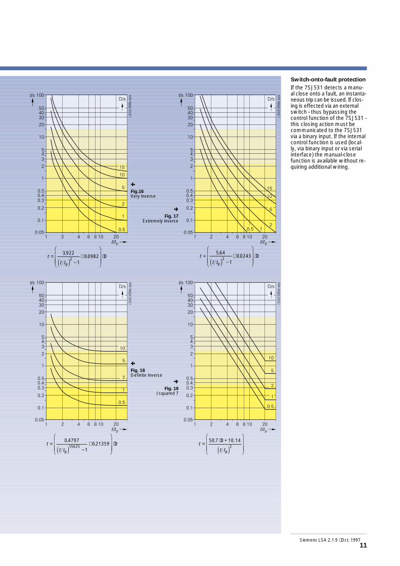
Inverse-time characteristicsacc. to ANSI/IEEE• Inverse• Short inverse• Long inverse• Moderately inverse• Very inverse• Extremely inverse• Definite inverse• I squared T
• t = tripping time in s• I = measured current• Ip = settable
threshold value0.1 to 4 I/IN
• D = time multiplier
Note for Figs. 12 to 19Scope of I/Ip from 1.1 to 20
ç
Fig.12Inverse
è
Fig. 13Short inverse
ç
Fig. 14Long inverse
è
Fig. 15Moderately
inverse
Functions
10 Siemens LSA 2.1.9 ⋅ Oct. 1997
t =−
+F
HGGG
I
KJJJ
⋅89341
101796620938
.. D
p.
I Ie jt =
−+
F
HGGG
I
KJJJ
⋅02663
100339312969
.. D
p.
I Ie j
t =−
+F
HGG
I
KJJ ⋅
5 6143
1218592
.. D
pI Ie jt =
−+
F
HGGG
I
KJJJ
⋅00103
100228002
.. D
p.
I Ie j
SIPROTEC 7SJ531 (Version V3.2)Numerical Line and Motor Protection with Control Functions
Siemens LSA 2.1.9 ⋅ Oct. 199711
ç
Fig.16Very inverse
è
Fig. 17Extremely inverse
ç
Fig. 18Definite inverse
è
Fig. 19I squared T
t =−
+F
HGGG
I
KJJJ
⋅3922
1009822
.. D
pI Ie jt =
−+
F
HGGG
I
KJJJ
⋅564
1002432
.. D
pI Ie j
t =−
+F
HGGG
I
KJJJ
⋅04797
102135915625
.. D
p.
I Ie jt =
⋅F
HGGG
I
KJJJ
5072
. D+10.14
pI Ie j
Switch-onto-fault protection
If the 7SJ531 detects a manu-al close onto a fault, an instanta-neous trip can be issued. If clos-ing is effected via an externalswitch - thus bypassing thecontrol function of the 7SJ531 -this closing action must becommunicated to the 7SJ531via a binary input. If the internalcontrol function is used (local-ly, via binary input or via serialinterface) the manual-closefunction is available without re-quiring additional wiring.

Functions
Directional earth-fault detec-tion (ANSI 64, 67G)
For isolated and compensatednetworks the 7SJ531 offers adirectional earth-fault detec-tion. The energy flow directionin the zero sequence systemis established on the basis ofthe zero sequence current I0
and the zero sequence voltageV0. In networks with isolatedstarpoint the content of the re-active current is evaluated,whereas in compensated net-works evaluation is based onthe active currents. Harmonicsare efficiently suppressed bymeans of a powerful numericalfilter. For particular networkconditions, e.g. for high-resi-stance earthed networks withcapacitive earth-fault current orlow-resistance earthed net-works with ohmic inductive cur-rents, the tripping charac-teristic can be rotated by ± 45degrees (see Fig. 20).Because of the low content ofthe active current in compensa-ted networks, it is recommen-ded to connect the sensitiveearth - current input to a core-balance current transformerand to connect the V0 input toan open delta winding. It isalso possible to evaluate the V0
voltage on the basis of thethree phase-to-earth voltagesand to emulate the earth cur-rent by means of a Holmgreencircuit. In general, this is quitesufficient for isolated networks.The directional earth-fault de-tection can be operated withthe tripping option or in the”annunciation-only” mode.The following functions are im-plemented:• TRIP via displacement volt-
age VE
• Two definite-time stages:IEE>> and IEE> or alternative-ly a definite-time stageIEE>> and a user-definablecharacteristic.
Each stage can be operated ei-ther forward, reverse or non-di-rectionally.
Directional overcurrent-timeprotection (ANSI 67, 67N)
The directional detection in the7SJ531 is phase-selective andis carried out separately forphase and earth faults. The sta-ges for the directional detec-tion run parallel to the non-di-rectional overcurrent stagesand can be set independentlyof these with regard to thepick-up values and the delay-times. There are two stagesfor both phase and earth, theovercurrent stages having ei-ther definite-time or inverse-time characteristics while thehigh-set current stages alwayshave a definite-time charac-teristic. The directional overcur-rent-time protection compri-ses the following features:• Separate settings for phase-
to-phase and phase-to-earthfaults
• Directional detection for pha-se-to-phase faults by meansof the short-circuit currentand the healthy phase-to-pha-se voltage
• Directional detection forearth faults on the basis ofdisplacement voltage VE andzero sequence current I0
• Evaluation of the displace-ment voltage either on thebasis of the phase voltagesor by using an open deltawinding
• Voltage storage, if voltagesdrop below the measuringlimit.
SIPROTEC 7SJ531 (Version V3.2)Numerical Line and Motor Protection with Control Functions
12 Siemens LSA 2.1.9 ⋅ Oct. 1997
Fig. 20Directional determination using cosine measurementsfor compensatednetworks
Fig. 21Directional characteristic of the directionalovercurrent-time protection
reverse
forward
inductive
capacitive
reverse forward
Correction = +15°
directional

Reserve interlocking on dou-ble-end fed line(cross connection)
This function is used forselective protection of sec-tions with infeed from both si-des (e.g. segments of closedrings), without the disadvanta-geous delay of grading inter-vals. The directional compari-son protection is suitable if theindividual protection units arenot too far apart and if pilot wi-res are available for signaltransmission. In addition to thedirectional comparison protec-tion, which provides the mainprotection, the directional gra-ded overcurrent-time protec-tion serves as a fully selectiveback-up protection. If operatedwith signal transmission dur-ing quiescent state an inter-ruption of the transmission issignalled.
Voltage protection
When phase-to-earth voltagesare connected, either phase-to-earth or phase-to-phase volt-ages can be evaluated. The lat-ter remains unchanged in theevent of an earth fault (isolatedor compensated networks).
Overvoltage protection(ANSI 59)
To protect equipment againstovervoltage an overvoltage sta-ge with a definite delay timehas been integrated. In orderto achieve a reset when a feed-er is tripped and the voltagetransformer is positioned onthe busbar side, the current ofthe feeder can be evaluated inthe derivation of fault detec-tion.
Undervoltage protection(ANSI 27)
To protect equipment againstundervoltage two stages withdefinite-time delay are provid-ed. To prevent permanentfault detection after trip of cir-cuit-breaker, provided the volt-age transformers are locatedon the feeder side, the currentof the feeder can be evaluatedin the derivation of fault detec-tion.Using a startup criterion, thepickup threshold can be chan-ged for the duration of startupwhen a motor is connected.This allows for the fact that dur-ing startup of the motor lesssevere voltage dips can be tole-rated than during rated opera-tion.
Breaker-failure protection(ANSI 51BF)
If a fault is not cleared after aprotective trip command, afurther command can be releas-ed by means of the breaker-failure protection, for instance acommand which will affect thecircuit-breaker of an up-streamprotective device. The breakerfailure is detected by the factthat current is still flowing inthe respective feeder after thetrip-command. As an alterna-tive, the auxiliary contact feed-back of the circuit-breaker canbe referred to.
Siemens LSA 2.1.9 ⋅ Oct. 1997 13
Fault locator
Indicates the distance to thefault location in kilometers ormiles, or indicates the secon-dary loop reactance. The faultlocation can be evaluated ei-ther after drop-off, after a tripcommand or by triggering via abinary input. This means thatthe fault location can also beevaluated when tripping is in-itiated by another protectiondevice.
Automatic reclosure(ANSI 79)
The 7SJ531 is equipped withautomatic reclosure. If thefault is still present even afterthe last reclosing cycle, lock-out is established. The possi-ble functions are:• 3-pole tripping• Separate settings for phase-
to-phase and phase-to-earthfaults
• Multiple reclosure, rapidauto-reclosure (RAR) and upto nine delayed auto-reclosu-re cycles (DAR)
• Auto-reclose trigger depend-ing on the stage selectivetrip command, e.g.− high-set overcurrent stage
phase− overcurrent stage phase− high-set overcurrent stage
earth− overcurrent stage earth− corresponding directional
short-circuit stages− unbalanced-load protection
• Option of blocking auto-reclosure via binary input
• External triggering of auto-reclosure
• Blocking of the directionaland non-directional high-setovercurrent stages duringthe RAR cycle.
Fig. 22Directional comparison protection
Faultde-tection
Faultde-tection
BlockingFault detection of non-directionalI> stageDirection of short-circuit

Functions
Fig. 23Tripping charac-teristics for completememory without pre-vious load and at90 % of previous load
Fig. 24Characteristic of theunbalanced-load pro-tection function
14 Siemens LSA 2.1.9 ⋅ Oct. 1997
Unbalanced-load protection(ANSI 46)(see Fig. 24)The unbalanced-load protectionmakes it possible to detect onthe HV side high-resistancetwo-pole faults as well as single-pole faults located on theLV side of a transformer e.g.with vector group Dy. Thus aback-up protection for high-re-sistance faults is providedwhich extends across the en-tire transformer.
Applied to a motor, the unba-lanced-load protection servesto detect phase failures or un-balanced loads which are dueto network unbalance, and toprotect the rotor against exces-sive temperature rise.For detection of the unbalan-ced load, the ratio negative-se-quence current by rated cur-rent is evaluated. There aretwo definite-time stages.
ParameterSet valueTime constantτ/min
ParameterSet valueTime constantτ/min
Unbalanced-loadzone I2>
Unbalanced-loadzone I2>>
Tripping characteristic
SIPROTEC 7SJ531 (Version V3.2)Numerical Line and Motor Protection with Control Functions
Thermal overload protection(ANSI 49)
For the protection of cables ormachines, an overload protec-tion with an alarm stage for tem-perature and current is imple-mented. The temperature isdetermined using a thermal ho-mogeneous body model (acc.to IEC 255-8) that takes into ac-count energy input to theequipment and energyoutput to the environmentand which constantly compen-sates the temperature.Thus previous loading andload fluctuations are taken intoaccount.Given constant current, thetripping time t is calculated ac-cording to the following form:
t = τ ⋅ ln
• t = tripping time after begin-ning of the overload
• τ =thermal time constant• Ipre = pre-load current• I = overload current• k = k-factor (in accordance
with IEC 255-8)• ln = natural logarithm(see Fig. 23)
For the thermal protection ofmotors (particularly of the sta-tor) an additional time constantτ can be selected to ensurethat the thermal conditions arecorrectly established bothwhen the motor is running andwhen it is at rest.The model automaticallyworks correctly, if the equip-ment is operated within the lim-its of the ambient temperaturefor which the producer hasspecified the maximum load-ing current. Substantial varia-tions of the ambient tempera-ture (e.g. the summer - winter- difference) can be accountedfor via a second parameter set.
I
I
I
I
I
I
k k
k
⋅FHG
IKJ
−⋅
FHG
IKJ
⋅FHG
IKJ
−
N
pre
N
N
2 2
2
1

Starting time monitoring(ANSI 48)
The starting time monitoringprotects the motor against un-duly prolonged start-ups,which may occur if for instan-ce too high load torques areexistant, if too severe voltagedips occur when the motor isbeing switched on or if the ro-tor is blocked. An occurranceof the latter type can be com-municated to the 7SJ531 via abinary input, so that an instanta-neous disconnection is effect-ed. The tripping time is current-dependent. It is obtainedaccording to the followingequation:
tTRIP =
• tTRIP = tripping time• IStart = starting current of
the motor• tStart max = maximum permis-
sible starting time• Irms = actual flowing current
(measured variable)
Using the above formula forthe tripping time, even prolong-ed start-ups with reducedvoltage (and reduced startingcurrent) are correctly evaluat-ed.
Start inhibit
If a motor is started too fre-quently in succession, the ro-tor, in particular the upper ed-ges of the bars, can be subjectto thermal overloading. Thestart inhibit permits starting ofthe motor only if the rotor hasenough thermal reserve for acomplete start.
Emergency start
This function disables the startinhibit via a binary input. In thiscase, the status of the thermalreplica is retained as long asthe binary input is active. It isalso possible to reset the ther-mal replica to zero.
I
ItStart
rmsStart max
FHG
IKJ
⋅
Undercurrent monitoring(ANSI 37)
This function permits detec-tion of a spontaneous currentdrop-off which may occur dueto reduced motor loading.Thus it is possible to detectshaft damage, no-load opera-tion of pumps or blower failure.
Siemens LSA 2.1.9 ⋅ Oct. 1997 15
Fig. 25Characteristic of startingtime monitoring
= start-up currentof the motor
= maximum per-missible startingtime
= pick-up setting offunction

Busbar protection(Reverse interlocking)The high-set stages of the pro-tection devices can be blockedvia a binary input (NC or NOcontact). In this manner the7SJ531 protection device pro-vides a simple and fast protec-tion for single busbars with sin-gle-end infeed.
Transformer protection
The high-set stage allows cur-rent grading, the overcurrentstages operate as a backup pro-tection for the downstream pro-tection devices and the over-load function protects thetransformer against thermaloverload. Weak-current single-pole faults on the low-voltageside which appear on the high-voltage side in the negativephase-sequence system canbe detected by the unbalanced- load function.
Typical applications
Fig. 27Typical protectionof a transformer
16 Siemens LSA 2.1.9 ⋅ Oct. 1997
TRIP TRIP TRIP TRIP
I>> block
Rel
ay1
Rel
ay2
Rel
ay3
Tripping time TI>>Tripping time t1Backup time TI>
Relay 1Relay 3Relay 1
SIPROTEC 7SJ531 (Version V3.2)Numerical Line and Motor Protection with Control Functions
Fault location A:Fault location B:
Fig. 26Busbar protection byreverse interlocking
Supply feeder

Motor protection
Stage I>> and IE>> can beapplied for short-circuit protec-tion. For isolated networks thesensitive earth-fault detectionfunction (IEE>>, V0>) can beused. Protection is providedfor the stator against thermaloverload (ϑs>) and for the rotor(I2>, starting-time monitoring,start inhibit). Via a binary inputa locked rotor can be detectedand switched off. The under-voltage function prevents start-ing when voltage is too low,the overvoltage functionaverts damages of the insula-tion.
Fig. 29Typical protection ofa medium-voltagering system
Siemens LSA 2.1.9 ⋅ Oct. 1997 17
Automaticreclose
Automaticreclose
Line protection
Simple ring systems withinmedium-voltage overhead sys-tems can be protected asshown in Fig. 29.At the supply terminals anauto-reclose can be employed;the other devices are equippedwith directional overcurrent-time protection.
Fig. 28Typical protectionof a high-voltageasynchronousmotor
Lockedrotor
Starting-timemonitoring
Startinhibit
Tachome-ter

18 Siemens LSA 2.1.9 ⋅ Oct. 1997
SIPROTEC 7SJ531 (Version V3.2)Numerical Line and Motor Protection with Control Functions
Standard connection
For earthed networks theearth current is derived via theHolmgreen circuit from thephase currents.Provided the premise0.1 IN < Iearth < 1.5 Asecondary ismet, the Holmgreen circuitcan be used.The sensitive IEE transformerhas to be looped in the earthcurrent circuit. If the earth cur-rent does not comply with thea.m. premise a core-balancecurrent transformer accordingto Fig. 30 is required.
Connection for compensat-ed networks
The diagram shows the con-nection of two phase-to-earthvoltages and the VE voltages ofthe open delta winding and acore-balance current transform-er for the earth current.This connection provides maxi-mum accuracy in directionalearth-fault detection and shouldbe applied in compensated net-works.
Typical applications
Version for panel surface mounting
Version for panel flush/cubicle mounting
Version for panel surface mounting
Version for panel flush/cubicle mounting
Fig. 31Connection ofa open deltawinding
Fig. 30Connection to3 voltage trans-formers
Important! Earthing of cable shield at outgoing cable!Note: Switching of current polarity (parameter address 1101)
causes polarity reversal of current input IEE!
Important! Earthing of cable shield at outgoing cable!Note: Switching of current polarity (parameter address 1101)
causes polarity reversal of current input IEE!

Siemens Lsa 2.1.9 ⋅ Oct. 1997 19
ÿConnection for isolated orcompensated networks only
If no directional earth-fault de-tection is used, a connectionwith two phase-current trans-formers is sufficient. For the di-rectional phase-overcurrent-time protection the phase -to-phase voltages detected bytwo primary voltage transfor-mers are sufficient.
Version for panel surface mounting
Version for panel flush/cubicle mounting
Fig. 32Connection to twocurrent and two voltagetransformers
Overview of connection types
Function Type of network Current connection Voltage connectionOvercurrent-time protection, (low-resistance) Holmgreen circuit, needed with –phases/earth fault, non-directional earthed networks 3 phase-current transformers, earth
with core-balance current-transformerspossible
Overcurrent-time protection, isolated or compen- Holmgreen circuit, possible with –phase fault, non-directional sated networks 3 or 2 phase-current transformers
Overcurrent-time protection, (low-resistance) Holmgreen circuit, needed with phase-to-earth connection orphase fault, directional earthed networks 3 phase-current transformers phase-to-phase connection
Overcurrent-time protection, (low-resistance) Holmgreen circuit, needed with phase-to-earth connectionearth fault, directional earthed networks 3 phase-current transformers, core- needed
balance current transformers possible
Overcurrent-time protection, isolated or compen- Holmgreen circuit, possible with phase-to-earth connection orphase fault, directional sated networks 3 or 2 phase-current transformers phase-to-phase connection
Sensitive earth-fault protection, isolated networks Holmgreen circuit, if 0.1 IN < earth 3 x phase-to-earth connectionsin ϕ measurement current < 1.5 A secondary, otherwise or phase-to-earth connection
core-balance current transformer needed with open delta winding
Sensitive earth-fault protection, compensated networks core-balance current transformers phase-earth connection withcos ϕ − measurement needed open delta winding
Sensitive earth-fault protection (low-resistance) core-balance current transformers –earthed networks needed

Technical data
Inputcircuits
Voltagesupplyvia integratedDC/DCconverter
Rated current IN 1 or 5 ARated voltage VN 100 to 125 VRated frequency fN 50 or 60 HzThermal overload capability in voltage path, continuous 140 V
in current path, continuous 4 x IN1 s 100 x IN
Dynamic overload capability (half cycle) 250 x IN
Power consumption, voltage inputs Approx. 0.5 VAcurrent inputs at IN = 1 A Approx. 0.1 VA
at IN = 5 A Approx. 0.2 VA
Rated auxiliary voltage Vaux / permissible tolerance 24, 48 V DC / 19 to 56 V DC60, 110, 125 V DC / 48 to 144 V DC220, 250 V DC / 176 to 288 V DC
Max. ripple at rated voltage ≤ 12 %Power consumption, quiescent Approx. 12 W
energized Approx. 23 WMax. back-up time during loss of auxiliary voltage ≥ 50 ms for Vaux ≥ 110 V DC
Number 11, for each switching device 1 pairpermanently assigned, the rest freely assignable
Voltage range 24 to 250 V DCCurrent consumption independent of operating voltage Approx. 2.5 mA
Number of relays with 1 C/O contact each 4 (marshallable)Alarm/event relay with C/O contact 1Switching capacity make/break 20 W/ VASwitching voltage 250 V AC/DCPermissible current, continuous 1 A
Number of relays with 1 NO contact each 2 (marshallable)with 2 NO contacts each 2 (marshallable)
Switching capacity make 1 000 W/ VAbreak 30 W/ VA
Switching voltage 250 V AC/DCPermissible current continuous 5 A
0.5 s 30 A
Ready indication green 1Fault indication red 1Marshallable LEDs red 6
Operator interface non-isolated, on front panelconnection 9-way sub connectorbaud rate 1 200 to 19 200 Bd
Potential-free interface for connection to a control centrestandard Protocol to DIN 19 244baud rate 4 800 to 19 200 Bdfibre-optic connection integrated FSMA connector for connection
to fibre-optic cables at rear sideoptical wavelength 820 nmpermissible attenuation Max. 8 dbdistance Max. 1.5 kmno character Switchable, supplied “light off“
Housing, dimensions 7XP20, see dimension drawingsWeight flush mounting/cubicle mounting Approx. 9.5 kgDegree of protection according to EN 60529 IP 51
DIN VDE 0435, Part 303 and IEC 255-5 or IEC 255-6 –
High-voltage test 2 kV (rms), 50 Hz; 1 min oralternatively 2.8 kV DC; 1 min
Impulse voltage test 5 kV (peak); 1.2/50 µs; 0.5 J;3 positive and 3 negative shotsin intervals of 5 s
Alarm/eventcontacts
Commandcontacts
LEDs
Unitdesign
20 Siemens LSA 2.1.9 ⋅ Oct. 1997
Binary inputs
Serial interfaces
Standards
Insulationtests
SIPROTEC 7SJ531 (Version V3.2)Numerical Line and Motor Protection with Control Functions

Disturbancetests
Overvoltageprotection
Undervoltageprotection
Siemens LSA 2.1.9 ⋅ Oct. 1997 21
High-frequency test 2.5 kV (peak); 1 MHz; τ = 15 µs,(1MHz test) 400 shots per second; duration 2 sIEC 255-22-1, class IIIElectrostatic discharge 8 kV (peak); 5/30 ns;(ESD test) 10 positive dischargesIEC 255-22-2, class IIIElectromagnetic fields Frequency 27 to 500 MHz; 10 V/m(Radiated electr. magn. field test)IEC 255-22-3, class IIIFast transient test 2 kV (peak); 5/50 ns; 5 kHz;IEC 255-22-4, class III 4 mJ per impulse; 1 min per polarity
Conducted interference voltage, aux. voltage 150 kHz to 30 MHzCISPR 22, EN 55022, DIN VDE 0878 Part 22 limit value class BInterference field strength 30 to 1000 MHzCISPR 11, EN 55011, DIN VDE 0875 Part 11 limit value class A
Permissible ambient temperature in service -5 to +55 °Cduring storage -25 to +55 °Cduring transport -25 to +55 °C
Humidity rating Annual average ≤ 75 % relative humidity,on 30 days per year up to 95 % relativehumidity; condensation not permissible
Permissible mechanical stress in service 10 to 60 Hz: 0.035 mm amplitude60 to 500 Hz: 0.5 g acceleration
during transport 5 to 8 Hz: 7.5 mm amplitude8 to 500 Hz: 2 g acceleration
Overcurrent phase I> / phase Idir.> I/ IN = 0.1 to 25, infinityearth IE> / earth IE dir.> I/ IN = 0.05 to 25, infinity
High-set current phase I>> / phase Idir.>> I/ IN = 0.1 to 25earth IE>> / earth IE dir.>> I/ IN = 0.05 to 25
Delay times 0 to 60 s or infinityTolerances
Current pick-up value ±5 % of set valueTime ±1% or ±10 msReset time Approx. 30 ms
Overcurrent phase Ip / phase Ip dir .> Ip/ IN = 0.1 to 4 / Ip dir. /IN = 0.1 to 4earth IEp / earth IEp dir. > IEp/ IN = 0.05 to 4 / IEp dir. / IN = 0.05 to 4
High-set current phase I>>(definite time, ANSI 51) / I/ IN = 0.1 to 25phase Idir. >>(definite time, ANSI 51)earth IE>> (definite time, ANSI 51) / I/ IN = 0.05 to 25earth IE dir. >>(definite time, ANSI 51)
Time multiplier tp 0.05 to 3,2 s and infinityPick-up value 1.1 x Ip
Characteristics according to IEC 255-4, Normal inverse, very inverse, extremelySection 3.5.2 or BS 142 and ANSI C37 inverse, I/ Ip = 1 to 20, definite time char-
acteristic above 20 x Ip
TolerancesPick-up values I>>, IE>>, Ip, IEp 3 % of setting valueDelay time for 2 ≤ I/Ip ≤ 20 5 % of setting value
additionally 2 % current tolerance or 30 ms
Overvoltage V> 40 to 130 VDelay time tu> 0 to 60 s and infinityTolerances
Voltage thresholds 3 % of set valueDelay times 1 % or 10 ms
Undervoltage V< 30 to 120 VV<< 30 to 120 V
Reset ratio r 1.05 to 3Delay time tu< 0 to 60 s and infinity
tu<< 0 to 60 s and infinityTolerances
Voltage thresholds 3 % of set valueDelay times 1 % or 10 ms
EMCtests,emission(type tests)Standard:50081-¨ (genericstandard)
Climaticconditions
MechanicalstresstestsIEC68Parts2 -6IEC255Part21,1
Inverse-timeovercurrentprotectionnon-directional/directional
Definite-timeovercurrentprotectionnon-directional/directional

Auto-reclose function
Earth-faultprotection
Circuit-breaker failureprotection
SIPROTEC 7SJ531 (Version V3.2)Numerical Line and Motor Protection with Control Functions
Factor k 0.1 to 4Time constant τ 1 to 999.9 minAlarm temperature ΘAlarm 50 to 100 %Current alarm stage IAlarm 0,1 to 4 x I/ IN
Prolongation factor at stand-still 1 to 10referring to time constant withrunning engine, factor τTolerances
Referring to k ⋅ IN 5 % class index acc. to IEC 255-8Referring to trip time 5 % ± 2 s; class index acc. to IEC 255-8
Number of possible auto-reclosures, 3-pole 1 rapid auto-reclosureup to 9 delayed auto-reclosures
Program for phase faultsInitiation possible with High-set O/Current I>>
Overcurrent DMT I >, IDMT Ipdirectional stages, unbalanced-load protection
Program for earth faultsInitiation possible with High-set E/F IE>>
Overcurrent DMT IE >, IDMT IEpdirectional stages, unbalanced-load protection
Action times 0.01 to 320 s and ∞Dead time RAR 0.01 to 320 sDead times DAR 0.01 to 1 800 sReclaim time 0.5 to 320 sBlocking times 0.5 to 320 s and ∞Close command duration 0.01 to 32 s
Earth-fault detection with displacement voltage VE> 2 to 130 VFaulted phase indication (only with directional option)
VPH-E < the faulted phase 10 to 100 VVPH-E >the healthy phase 10 to 100 VMeasuring tolerance according to VDE 0435 part 303 ≤ 5 % of set value(for sinusoidal quantites)
Directional determinationMeasuring principle Active/reactive power calculationEarth-faut current IEE>/IEEP (active and reactive) 3 to 1 600 mAAngle correction for core balance current transformer 0 to 5° in 2 CT operating pointsAdjustment of directional characteristic - 45 to +45°Measuring tolerance according to VDE 0435 part 303 ≤ 10 % of set value(for sinusoidal quantites)
Triggering threshold I> 0.04 to 1 x I/ IN
Delay time tbreaker-failure protection 0.06 to 60 s or infinityTolerances
Pick-up value 3 % of setting valueDelay time t 1 % of setting value or 20 ms
Setting rangeTripping stage I2>, I2>> in steps of 1% 5 to 80 % of INTime delays T(I2>), T(I2>>) in steps of 0.01 s 0 to 60 sLower function limit at least one phase current ≥ 0,1 x IN
Higher function limit all phase currents ≤ 4 x IN
TolerancesPick-up values I2>, I2>> current I/ IN ≤1.5 ±1 % of IN ±5 % of set value
current I/ IN >1.5 ±5 % of IN ±5 % of set valueStage delay times T(I2>), T(I2>>) ±1 % or 10 ms
Setting rangesStart-up current of the motor Istart /IN 1 to 16Pick-up threshold Istart en../IN 0.6 to 10Permissible start-up time Tstart max. 1 to 180 sPermissible locked-rotor time Tlock. rot. 0.5 to 120 s or ∞
TolerancesPick-up value 3 %Delay time t 5 % of setting value or 30 ms
Unbalanced-loadprotection
Startingtimemonitoringformotors
22 Siemens LSA 2.1.9 ⋅ Oct. 1997
Technical data (continued)
Overloadprotection

Fault recording
Setting rangesStart-up current referred to rated motor current IA/IB 3 to 10Rated motor current, rated transformer current IB/IN 0.2 to 1.2Max. permissible start-up time Tstart. max. 3 to 120 sRotor temperatur-delay time Tdelay 0 to 60 minMax. permissible hot starts nh 1 to 4Difference between hot and cold starts nc − nh 1 to 2Prolongation factor for time constant 1 to 10of rotor; stand still kτL
Output of fault distance in Ω secondary,in km or mile line length
Start-to-measure command by trip signal or drop-off of fault detectionor by external command via binary input
Setting reactance per unit line length (secondary) 0.01 to 10 Ω/miles, 0.006 to 6.215 Ω/km
Measuring tolerances acc. to VDE 0435 part 303 ≤ 2,5 % of line length (without intermediatesinusoidal quantities infeed) 30° ≤ ΦK ≤ 90° and VSC/VN ≥ 0.1
Measured values i L1, i L2, i L3, i E, v L1, v L2, v L3, v E
Start signal Trip, fault detection, binary input, LSA/SCADA,integrated operating panel
Recording duration Max. 5 sHolding time Until fault-recording buffer full. New fault
entries overwrite the oldest recordedfaults.
Currents IL1, IL2, IL3, IEVoltages VL1, VL2, VL3, V12, V23,V13, V0Powers P, QPower factor cos ϕEnergies Wp+, Wp-, Wq+, Wq-Frequency fThermal replica Θ, ΘR
Measuring ranges 0 to 240 % IN0 to 120 % VNP, Q are represented if all voltages and cur-rents are within the valid range.
This product is in conformity with the directives of the Council ofthe European Communities on the approximation of the laws ofthe Member States relating to the electromagnetic compatibility(EMC Council Directive 89/336/EEC) and concerning electricalequipment for use within specified voltage limits (low-voltagedirective 73/23/EEC). The product conforms with the internationalstandard IEC 255 and the national standard DIN 57 435 part 303.The relay is designed for use in an industrial environment acc. to theEMC standard specification.Conformity is proved by tests performed by Siemens AG in line witharticle 10 of the Council Directives in accordance with the genericstandards EN 50081-2 and EN 50082-2 for the low-voltage directive.
Operationalmeasuredvalues
CE-conformity,standards
Siemens LSA 2.1.9 ⋅ Oct. 1997 23
Fault location
Start inhibitformotors

Selection and ordering data
SIPROTEC 7SJ531 (Version V3.2) 7SJ531o –ooAo2 –ooAo
Numerical line and motor protection with control functions
Rated current at 50/60 Hz1 A5 A
Auxiliary voltage Vaux for integrated DC/DC converter24, 48 V DC60, 110, 125 V DC220, 250 V DC
ConstructionHousing 7XP2030-1 for panel surface mounting without glass coverHousing 7XP2030-2 for panel flush mounting/cubicle mountingwith Weidmüller terminals without glass cover
LanguagesGerman/EnglishGerman/FrenchGerman/Polish
Function rangewith wattmetric earth-fault detection, with auto-reclosewith wattmetric earth-fault detection, without auto-reclosewithout wattmetric earth-fault detection, with auto-reclosewithout wattmetric earth-fault detection, without auto-reclose
Serial system interfacewithout serial system interfacewith serial 820 nm fibre-optic module (FSMA connector)
Directional overcurrent-time protectionwithoutwith
Manual 7SJ531German C53000 - G1100 - C114-1English - G1176 - C114-1French - G1177 - C114-1Polish - G1155 - C114-1
DIGSI (Operating and analysis software 7XS5020 –oAA00
for numerical protection devices)
Operating languagesGermanEnglishFrench
Designation Order No.
15
245
BE
012
0123
SIPROTEC 7SJ531 (Version V3.2)Numerical Line and Motor Protection with Control Functions
24 Siemens LSA 2.1.9 ⋅ Oct. 1997
AC
01
012

Connection diagram
Fig. 33Connection diagram
Siemens LSA 2.1.9 ⋅ Oct. 1997 25
Version for panel flush mounting/cubicle mounting
Version for panel surface mounting
Alarm relay 1
Alarm relay 2
Alarm relay 3
Alarm relay 4
Malfunctionrelay
Commandrelay 1
Commandrelay 2
Commandrelay 3Commandrelay 4
Binaryinput 8
Binaryinput 9
Binaryinput 10
Binaryinput 11
Powersupply
Binaryinput 3
Binaryinput 4
Binaryinput 5
Binaryinput 6
Binaryinput 7
Binaryinput 1
Binaryinput 2
Fibre-optic interface connectionto the control unit

Fig. 347SJ531 with 7XP2030-2 housingfor panel flush mounting/cubicle mounting
Fig. 357SJ531 with 7XP2030-1 housingfor panel surface mounting with two-tier terminals
Dimension drawings (in mm)
26 Siemens LSA 2.1.9 ⋅ Oct. 1997
SIPROTEC 7SJ531 (Version V3.2)Numerical Line and Motor Protection with Control Functions
Front view Side view Panel cut out
Fibre-opticinterface
Diam. 5 or M 4
Front view Side view Detail Z
Fibre-optic interface
Cutout 20 x 60(without paint)

Siemens LSA 2.1.9 ⋅ Oct. 1997 27
Technical specification
The protective relays measur-ed value processing must becompletely numerical, i.e. allthe way from sampling and di-gitizing of the analog values upto the decision to trip the cir-cuit-breaker. The protective de-vice must feature completegalvanic and interference-freeisolation of the internal proces-sing circuits from the measur-ing und supply circuits of thesystem by means of shieldedinput, binary I/O modules andDC converters.It must be possible to applythe combined protection, con-trol and monitoring device innetworks with different typesof neutral point earthing. Con-trol of the switchgear musttake place via the integratedoperator panel, via binary in-puts or via an operating andanalysis program. Telecontrolof the protective device viamodem must be possible.
The motor protection func-tions must be suitable forasynchronous machines of allsizes. Both overvoltage andundervoltage protection func-tions for the motor must beavailable. The undervoltageprotection should have twostages. The starting timemonitoring must take accountof various starting currents. Itmust be possible to connectan external speed monitor tothe protective device, in orderto identify a locked rotor and toissue a non-delayed trip.The overcurrent-time protec-tion must be either definite-time or inverse-time, separate-ly selectable for phase andearth faults. It must be possi-ble to select from availablecharacteristic curves (acc. toANSI/IEEE and IEC) as well asfrom an user-defined overcur-rent-time characteristic. The in-verse-time overcurrent protec-tion should be able to evaluateeither the fundamental currentor the true rms value.
It must be possible to connect acore-balance current transform-er for sensitive earth-faultdetection. The phase andearth-fault characteristicsmust be directional. It must bepossible to rotate the trippingcharacteristic of the wattme-tric earth-fault detection forparticular network conditions.A fault locator should indicatethe distance to the fault loca-tion. Automatic reclosureshould permit a number ofreclosing operations.The operational measured val-ues should include meteredvalues for active and reactivework done and operating hourcount. It should be possible tocheck individual operationalmeasured values against setlimits. It should be possible toselect specific measured val-ues for indication in the graphicdisplay. The active and reactivepower should be provided forthe LSA/SCADA.The internal battery should bechecked at regular intervals bythe processor. If battery capa-city drops, an alarm should beinitiated.

Catalog Index of the Protection and Substation Control
Catalog Index
Title Designation Order No.
Measurement and Recording Systems
Fault Recorder OSCILLOSTORE SR 10.1 E50001-K4010-A101-A1-7600
Protective Relaying
7SJ41 Definite-Time Overcurrent Protection Relay LSA 2.1.10 E50001-K5712-A201-A2-76007SJ511 Numerical Overcurrent-Time Protection (Version V3) LSA 2.1.3 E50001-K5712-A131-A3-76007SJ512 Numerical Overcurrent-Time Protection (Version V3) LSA 2.1.4 E50001-K5712-A141-A3-76007SJ512 Numerical Feeder Protection LSA 2.1.30 E50001-K5712-A411-A1-76007SJ531 SIPROTEC Numerical Overcurrent Protection Relay LSA 2.1.9 E50001-K5712-A191-A4-76007SJ551 Multi-Function Protection Relay LSA 2.4.2 E50001-K5742-A121-A3-76007SJ600 SIPROTEC Overcurrent, Motor and Overload Protection LSA 2.1.15 E50001-K5712-A251-A2-76007SJ601 SIPROTEC Overcurrent Protection LSA 2.1.16 E50001-K5712-A261-A1-7600
7SA510 Distance Protection Relay (Version V3) LSA 2.1.17 E50001-K5712-A271-A1-76007SA511 Line Protection Relay (Version V3) LSA 2.1.11 E50001-K5712-A211-A2-76007SA513 Line Protection Relay (Version V3) LSA 2.1.12 E50001-K5712-A221-A1-76007SA518/519 Overhead Control-Line Protection Relay (Version V3) LSA 2.1.14 E50001-K5712-A241-A1-76003VU13 Miniature Circuit-Breaker LSA 2.1.8 E50001-K5712-A181-A2-7600
7SD502 Line Differential Protection with Two Pilot Wires LSA 2.2.1 E50001-K5722-A111-A2-76007SD503 Line Differential Protection with Three Pilot Wires LSA 2.2.2 E50001-K5722-A121-A2-76007SD511/512 Current Comparison Protection Relay (Version V3)for Overhead Lines and Cables LSA 2.2.3 E50001-K5722-A131-A2-76007UT512/513 Differential Protection Relay (Version V3)for Transformers, Generators and Motors LSA 2.2.4 E50001-K5722-A141-A2-7600
7SS5 Station Protection LSA 2.2.5 E50001-K5722-A151-A2-7600Auxiliary Current Transformers 4AM50, 4AM51, 4AM52and Isolating Transformers 7XR95 LSA 2.2.6 E50001-K5722-A161-A1-7600
7SN71 Transient Earth-Fault Relay LSA 2.3.2 E50001-K5732-A121-A1-76007VC1637 Earth-Leakage Monitor LSA 2.3.4 E50001-K5732-A141-A1-7600
7UM511 Generator Protection Relay (Version V3) LSA 2.5.2 E50001-K5752-A121-A2-76007UM512 Generator Protection Relay (Version V3) LSA 2.5.3 E50001-K5752-A131-A2-76007UM515 Generator Protection Relay (Version V3) LSA 2.5.4 E50001-K5752-A141-A2-76007VE51 Synchronizing Unit LSA 2.5.7 E50001-K5752-A171-A1-7600
7VK512 Numerical Auto-Reclose/Check-Synchronism Relay LSA 2.7.3 E50001-K5772-A131-A1-7600Test Switch 7XV72 LSA 2.7.8 E50001-K5772-A181-A1-76007VP151 Three-Phase Portable Test Set (Omicron CMC56) LSA 2.6.1 E50001-K5762-A111-A2-7600
Centralized and Remote Control of Siemens Protection Relays (Overview)* LSA 2.8.1 E50001-K5782-A111-A1-7600Operating and Analysis Software DIGSI V3* LSA 2.8.2 E50001-K5782-A121-A1-7600
Substation Control and Protection
Input/Output Unit 6MB522 LSA 1.1.1 E50001-K5701-A111-A4-7600Input/Output Unit 6MB523 LSA 1.1.2 E50001-K5701-A121-A2-76006MB511/6MB512 Substation Master Unit 7SW511/7SW512 Relay Data Concentrator LSA 1.1.3 E50001-K5701-A131-A2-76006MB520/6MB521 Input/Output Units LSA 1.1.4 E50001-K5701-A141-A1-76006MB513/514 Compact Control Master Unit and Relay Data Concentrator LSA 1.1.6 E50001-K5701-A161-A1-7600
6MB5510 Station Control Unit LSA 1.2.1 E50001-K5701-A211-A2-76006MB552 Compact Remote Terminal Unit LSA 1.2.2 E50001-K5701-A221-A1-76006MB5530-0 Minicompact Remote Terminal Unit LSA 1.2.3 E50001-K5701-A231-A1-7600
6MB5530-1 Minicompact Remote Terminal Unit for Cable Shield Communication LSA 1.2.4 E50001-K5701-A241-A1-76006MB5540 SINAUT LSA COMPACT Remote Terminal Unit LSA 1.2.5 E50001-K5701-A251-A1-76006MB5515 Station Control Unit LSA 1.2.6 E50001-K5701-A261-A1-7600
Control in SINAUT LSA Substation Control and Protection LSA 1.4.1 E50001-K5701-A411-A1-7600Status Indications in SINAUT LSA Substation Control and Protection LSA 1.4.2 E50001-K5701-A421-A1-7600Analog Values in SINAUT LSA Substation Control and Protection LSA 1.4.3 E50001-K5701-A431-A1-7600Metering in SINAUT LSA Substation Control and Protection LSA 1.4.4 E50001-K5701-A441-A1-7600
Voltage Control with Input/Output Units 6MB520/6MB521 LSA 1.4.5 E50001-K5701-A451-A1-7600Network Synchronization with Input/Output Units 6MB520/521 LSA 1.4.6 E50001-K5701-A461-A1-7600Operation with Two Control Master Units LSA 1.4.7 E50001-K5701-A471-A1-7600Node Functions in SINAUT LSA Substation Control and Protection LSA 1.4.8 E50001-K5701-A481-A1-7600System Management with the SINAUT LSA Substation Control and Protection System LSA 1.4.9 E50001-K5701-A491-A1-7600
LSADIAG - Testing and Diagnostics System for SINAUT LSA LSA 1.5.2 E50001-K5701-A521-A1-7600Substation Control and ProtectionLSACONTROL - Control and Monitoring LSA 1.5.3 E50001-K5701-A531-A1-7600LSAPROCESS - Process Information Analysis LSA 1.5.5 E50001-K5701-A551-A1-7600
LSA 678 Standard Cubicle LSA 1.6.1 E50001-K5701-A611-A1-7600
* Information on additional equipment for 7SJ531
Please contact yourSiemens representative
28 Siemens LSA 2.1.9 ⋅ Oct. 1997

Conditions of Sale and Delivery ⋅ Export RegulationsTrademarks ⋅ DimensionsConditions of Sale and Delivery
Export Regulations Dimensions
Subject to theGeneral Conditions of Supplyand Deliveryfor Products and Services ofthe Electrical and ElectronicIndustry and to any otherconditions agreed upon withthe recipients of catalogs.
The technical data, dimensionsand weights are subject tochange unless otherwise statedon the individual pages of thiscatalog.The illustrations are forreference only.We reserve the right to adjustthe prices and shall charge theprice applying on the date ofdelivery. En 1.91a
In accordance with the presentprovisions of the German ExportList and the US CommercialControl List, export licences arenot required for the productslisted in this catalog.
An export licence may howeverbe required due to country-specific application and finaldestination of the products.Relevant are the export criteriastated in the delivery note andthe invoice regarding a possibleexport and reexport licence.Subject to change without notice.
All dimensions in this catalogare given in mm.
Trademarks
All product designations usedare trademarks or productnames of Siemens AG or of othersuppliers.
Siemens online!
The Power Transmission andDistribution Group can also befound in the Internet:http://www.ev.siemens.de
Order No.: E50001-K5712-A191-A4-7600
Printed in GermanyKG K 1097 5.0 28 En 100184 6101/U652
Responsible forTechnical contents:Hans Heining-Triebs, Marko Zaherdoust,Siemens AG, EV S V13, NürnbergGeneral editing: Claudia Kühn-SutionoSiemens AG, EV BK T, Erlangen

BereichEnergieübertragung und -verteilungGeschäftsgebiet SekundärsystemePostfach 4806D-90026 Nürnberg
Siemens Aktiengesellschaft Order No.: E50001-K5712-A191-A4-7600