site-grading tips and tricks with autodesk® civil 3d · pdf filedecember 2-5, 2003 mgm...
TRANSCRIPT

December 2-5, 2003 ◊ MGM Grand Hotel Las Vegas
Site-Grading Tips and Tricks with Autodesk® Civil 3D Toby Jutras
CV43-1 Site grading is often described as more of an art than a science. In this session, we will examine techniques to create model-based grading solutions, featuring the latest in Autodesk's site-grading technology - Autodesk® Civil 3D. These completed designs, unlike the manual process, are ready for volume calculations, profiles, and cross sections. And the contours look great!
About the Speaker: Toby is a senior applications engineer with Autodesk, specializing in Civil Engineering Solutions products. Toby regularly presents at seminars and technical workshops. His understanding of the construction, civil engineering, and surveying fields comes from 10 years of experience working on engineering projects in New England. Toby has been the lead designer on a wide array of project types, including highway interchanges, fuel storage facilities, and retail/residential projects.


3
Table of Contents INTRODUCTION ..........................................................................................................................4
A SIMPLE POND DESIGN EXAMPLE ........................................................................................4
CREATING THE SLOPED POND BOTTOM ...............................................................................4 DEFINING A FEATURE LINE...........................................................................................................4 CREATING A CRITERIA SET ..........................................................................................................5 CREATING A GRADING GROUP .....................................................................................................6 GRADING FROM OUR FEATURE LINE ............................................................................................7 CREATING A SURFACE FROM A GRADING GROUP..........................................................................7 ADJUSTING THE POND BOTTOM SURFACE ....................................................................................8
CREATING THE POND INTERIOR AND EXTERIOR .................................................................9 DEFINING A FEATURE LINE...........................................................................................................9 CREATING A CRITERIA SET ........................................................................................................10 CREATING A GRADING GROUP ...................................................................................................10 GRADING THE POND INTERIOR ...................................................................................................11 GRADING THE POND EXTERIOR..................................................................................................12 FILLING VOIDS IN THE GRADING GROUP .....................................................................................12 CREATING A SURFACE FROM THE POND GRADING GROUP..........................................................13 CALCULATING CUT/FILL VOLUMES .............................................................................................13
SUMMARY .................................................................................................................................14

4
Introduction Grading design is often described to be as much art as science. Those that exhibit talent in drawing contours can often out perform many of the automated or computer assisted grading methods that exist in the industry today. So, why then is Autodesk Civil 3D worth taking a look at? It is because Autodesk Civil 3D defines a dynamic relationship between related engineering elements in a way that makes editing a design effortless. A simple grip edit of the original parking lot outline, can in an instant update the resulting contours, profiles, sections, and volume information.
A Simple Pond Design Example In the following example, we will put to use some of the concepts described above. Our example will consist of a small pond design example that leverages many of the different techniques that can be employed to create a grading in Autodesk Civil 3D.
Creating the Sloped Pond bottom Part of our pond design calls for a sloped bottom. This will ensure that the pond drains to one end, and maintain a dry state when it is not in use. There are several ways to create the sloped bottom effect, but in this example we will use a grading to create a plane at a 2% slope. Later, we will grade our pond interior to this plane, creating the sloped bottom effect.
Defining a Feature Line A feature line is generally used to mark the starting point of a grading, and can be created from any polyline (closed or open), line, or arc. In our case, we will be using a feature line as the basis for the 2% plane that we want to define as our pond bottom. Our feature line in this example will be at approximately a 45 degree angle to the pond to channel flow to the north east corner of the pond. In this example our feature line will begin as a simple line segment. 1. Type L for Line at the command line 2. Draw a line similar to the one shown to the left Once the line is drawn we can convert it into a feature line. 3. Grading -> Create Feature Line 4. Select the line 5. Select Enter

5
If you list the line now, it indicates that the line segment has been replaced with a feature line object. Right now, the feature line is at elevation 0, as that was the elevation the original line was drawn at. Next, we will use the elevation editor to modify the default elevations. 6. Grading -> Elevation Editor The elevation editor provides a mechanism to adjust both elevations, as well as the grade between vertices on the feature line. In our case, we would like to establish the elevation of our feature line to be 5584.7’ at both ends of the line. 7. Select the Elevation column for row 1 8. Change the elevation to 5584.7 9. Select the Grade column for row 1 10. Change the grade to 0% Because the first point is at elevation 5584.7, and the grade between the endpoints is 0, both endpoints are now at the same elevation.
Creating a Criteria Set With the feature line in place, we can now begin to think about projecting it’s elevation at a 2% slope to control the pond bottom shape. This is best accomplished using the grading layout tools provided in Autodesk Civil 3D. In order to make the process easier, Criteria Sets can be created that have a collection of predefined ways in which to grade. These criteria sets can be referred to over and over again, instead of repeating the same settings/procedure for each similar grading object. Furthermore, criteria sets can be saved in drawing templates, and used from project to project. Before we grade our feature line, we will create a simple criteria set for grading the pond bottom. 11. Select the Settings tab of the toolspace 12. Expand the Grading section 13. Expand the Grading Criteria Sets section 14. Right Click on the name of the criteria set
6
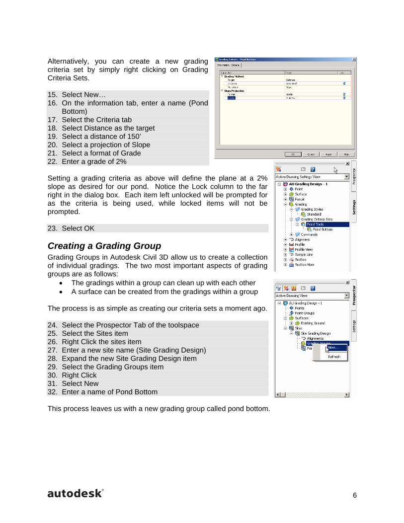
Alternatively, you can create a new grading criteria set by simply right clicking on Grading Criteria Sets. 15. Select New… 16. On the information tab, enter a name (Pond
Bottom) 17. Select the Criteria tab 18. Select Distance as the target 19. Select a distance of 150’ 20. Select a projection of Slope 21. Select a format of Grade 22. Enter a grade of 2% Setting a grading criteria as above will define the plane at a 2% slope as desired for our pond. Notice the Lock column to the far right in the dialog box. Each item left unlocked will be prompted for as the criteria is being used, while locked items will not be prompted. 23. Select OK
Creating a Grading Group Grading Groups in Autodesk Civil 3D allow us to create a collection of individual gradings. The two most important aspects of grading groups are as follows:
• The gradings within a group can clean up with each other • A surface can be created from the gradings within a group
The process is as simple as creating our criteria sets a moment ago. 24. Select the Prospector Tab of the toolspace 25. Select the Sites item 26. Right Click the sites item 27. Enter a new site name (Site Grading Design) 28. Expand the new Site Grading Design item 29. Select the Grading Groups item 30. Right Click 31. Select New 32. Enter a name of Pond Bottom This process leaves us with a new grading group called pond bottom.

7
Grading from Our Feature Line With both our feature line in place, and our criteria set defined, we can begin to project a grading. The Grading Layout Tools will be used in this process. 33. Grading -> Grading Layout Tools… The Grading Layout Tools command presents a toolbar with many options. 34. Select the set grading group button 35. Select the grading group Pond Bottom that was created in the
previous steps. If the dialog looks different from the one shown on the right, it is likely that you didn’t create the grading group as instructed in the previous steps. You can simply enter the name of your grading group in that dialog box instead. Because we have only one grading criteria set, and only one grading criteria, that is the default shown in the drop down box. Later as we develop additional grading criteria, it will be necessary to select the appropriate option from the drop down. 36. Select the Create Grading icon 37. Select the feature line 38. Select a point toward the pond 39. Answer yes to apply to entire length 40. Select Enter to complete the command
Creating a Surface from a Grading Group The last step in creating our pond bottom is to create a surface from the resulting grading group. In this case, the grading group is quite simple, as it has only the one grading in it. 41. Select the Create Surface from Group menu
item from the Grading Layout Tools toolbar 42. Confirm the group name Pond Bottom 43. Enter a surface name of Pond Bottom 44. Select a style other than Existing Ground 45. Select OK

8
Adjusting the Pond Bottom Surface With the surface created, now we can make some final adjustments. Because Autodesk Civil 3D supports dynamic relationships between related engineering elements, the process of making adjustments is quite easy. 1. Select the Prospector tab in the toolspace 2. Expand the surfaces group 3. Select the new surface Pond Bottom 4. Right click the mouse 5. Toggle on the option of Rebuild - Automatic The rebuild automatic option will enable automatic updates to the surface as the data it is built from changes. In our case , we would like to grip edit the original feature line, which will update the related grading elements, and as a result, update the surface, and contours which represent it. All of this from a simple grip edit. 6. Select the original feature line 7. Select one of the grips 8. Move the grip The resulting chain reaction updates the pond bottom surface. This can save considerable time when iterating through different design options, and fine tuning an existing design.

9
Creating the Pond Interior and Exterior The next part of our pond design is to create the pond interior and exterior. Each of these components will be defined using a different grading object, but they will both belong to the same grading group. The benefit of belonging to the same group, is that a single surface can be created from the combination of grading objects required to accomplish the desired result.
Defining a Feature Line In defining the feature line for the pond bottom, the line was converted to a feature line, and then it’s elevation adjusted. In this example, we will use simple AutoCAD tools to modify the elevation of the existing polylines, and then convert them to feature lines. Their modified elevations will remain intact after the conversion. 1. Select both polylines, representing the inside and outside of the
pond 2. Right click 3. Select Properties from the pop up menu 4. Select the Elevation 5. Change to 5585.4’ With the elevation selected, the polylines can be easily converted to feature lines. 6. Grading -> Create Feature Lines 7. Select both polylines 8. Select Enter To confirm that the polylines have been converted to feature lines, you can use the Elevation Editor to review the elevations along the perimeter of one of the polylines. 9. Grading -> Elevation Editor As you can see, all of the elevations along the perimeter of the feature line are 5585.4.
10
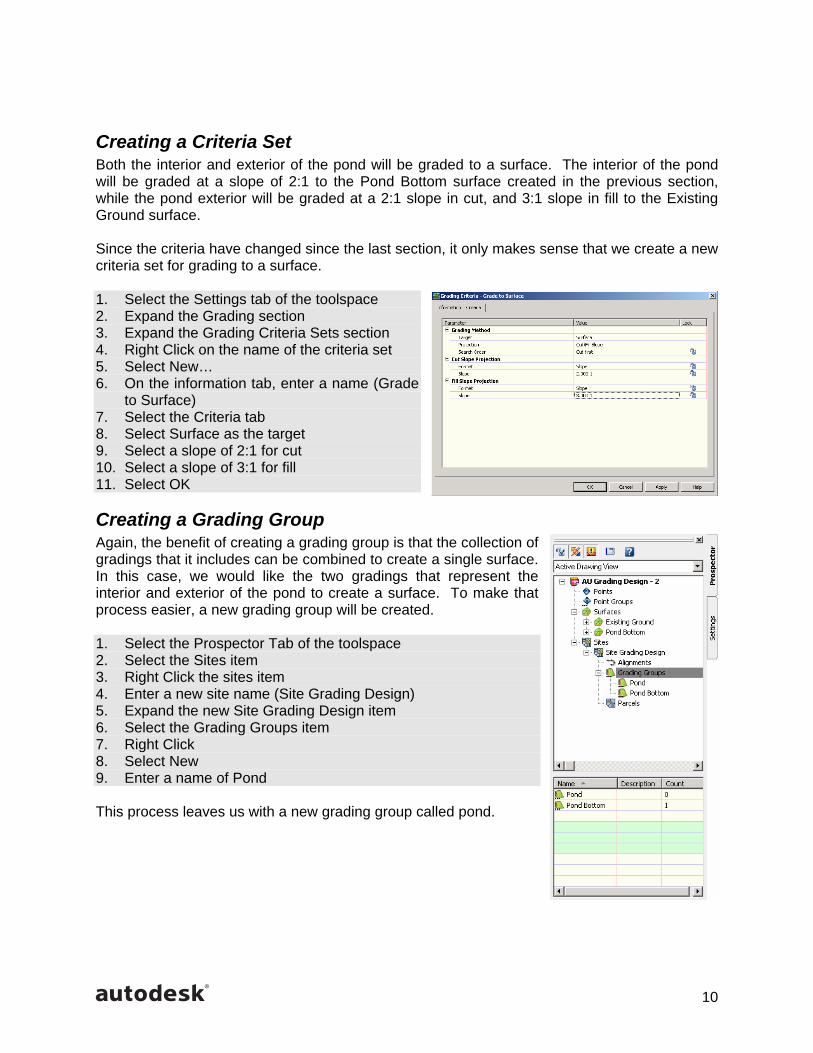
Creating a Criteria Set Both the interior and exterior of the pond will be graded to a surface. The interior of the pond will be graded at a slope of 2:1 to the Pond Bottom surface created in the previous section, while the pond exterior will be graded at a 2:1 slope in cut, and 3:1 slope in fill to the Existing Ground surface. Since the criteria have changed since the last section, it only makes sense that we create a new criteria set for grading to a surface. 1. Select the Settings tab of the toolspace 2. Expand the Grading section 3. Expand the Grading Criteria Sets section 4. Right Click on the name of the criteria set 5. Select New… 6. On the information tab, enter a name (Grade
to Surface) 7. Select the Criteria tab 8. Select Surface as the target 9. Select a slope of 2:1 for cut 10. Select a slope of 3:1 for fill 11. Select OK
Creating a Grading Group Again, the benefit of creating a grading group is that the collection of gradings that it includes can be combined to create a single surface. In this case, we would like the two gradings that represent the interior and exterior of the pond to create a surface. To make that process easier, a new grading group will be created. 1. Select the Prospector Tab of the toolspace 2. Select the Sites item 3. Right Click the sites item 4. Enter a new site name (Site Grading Design) 5. Expand the new Site Grading Design item 6. Select the Grading Groups item 7. Right Click 8. Select New 9. Enter a name of Pond This process leaves us with a new grading group called pond.

11
Grading the Pond Interior The grading layout tools will again be used to create the grading for the pond interior. 1. Grading -> Grading Layout Tools… 2. Select the set grading group button 3. Select the grading group Pond that was created in
the previous steps. Since we want to use different criteria to grade to a surface, we need to set that criteria from the criteria set drop down 4. Select the Grade to Surface option in the criteria
set drop down Since this grading criteria interacts with a surface, we need to set the surface to Pond Bottom. This will result in the pond grading to the sloped bottom we created in the earlier steps. 5. Select the 6. Set the surface to Pond Bottom 7. Select the Create Grading icon 8. Select the pond interior feature line 9. Select a point toward the pond interior 10. Accept the slope of 2:1 for cut 11. Accept the slope of 3:1 in fill 12. Answer yes to apply to entire length 13. Select Enter to complete the command The resulting interior line defines the intersection between our 2:1 slope, and the Pond Bottom surface.

12
Grading the Pond Exterior With the Grading Layout Tools still on the screen, we can move to create the exterior of our pond. While the grading criteria remains the same, the surface to which we will grade changes with this grading. Since our pond exterior grades into the Existing Ground surface, we must set that as the target surface. 1. Select the 2. Set the surface to Existing Ground 3. Select the Create Grading icon 4. Select the pond Exterior feature line 5. Select a point toward the pond exterior 6. Accept the slope of 2:1 for cut 7. Accept the slope of 3:1 in fill 8. Answer yes to apply to entire length 9. Select Enter to complete the command The resulting exterior line defines the intersection between our slope (2:1 in cut & 3:1 in Fill), and the Existing Ground surface.
Filling Voids in the Grading Group In our grading process, we have created void areas where no surface will be created. These voids are the interior of our pond, and the space between our interior and exterior gradings. The Grading Layout Tools provides a nice tool that allows these voids to be filled, so that the resulting surface will generate contours in these areas. There is no real way to control the interpolation of this tool, so anywhere you want specific control should be designed with an actual grading. The process for filling these voids is quite simple. 10. Select the Fill void area menu item 11. Select a point within the void to be filled
13
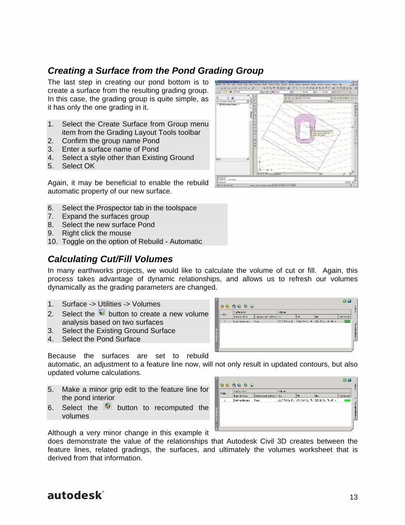
Creating a Surface from the Pond Grading Group The last step in creating our pond bottom is to create a surface from the resulting grading group. In this case, the grading group is quite simple, as it has only the one grading in it. 1. Select the Create Surface from Group menu
item from the Grading Layout Tools toolbar 2. Confirm the group name Pond 3. Enter a surface name of Pond 4. Select a style other than Existing Ground 5. Select OK Again, it may be beneficial to enable the rebuild automatic property of our new surface. 6. Select the Prospector tab in the toolspace 7. Expand the surfaces group 8. Select the new surface Pond 9. Right click the mouse 10. Toggle on the option of Rebuild - Automatic
Calculating Cut/Fill Volumes In many earthworks projects, we would like to calculate the volume of cut or fill. Again, this process takes advantage of dynamic relationships, and allows us to refresh our volumes dynamically as the grading parameters are changed. 1. Surface -> Utilities -> Volumes 2. Select the button to create a new volume
analysis based on two surfaces 3. Select the Existing Ground Surface 4. Select the Pond Surface Because the surfaces are set to rebuild automatic, an adjustment to a feature line now, will not only result in updated contours, but also updated volume calculations. 5. Make a minor grip edit to the feature line for
the pond interior 6. Select the button to recomputed the
volumes Although a very minor change in this example it does demonstrate the value of the relationships that Autodesk Civil 3D creates between the feature lines, related gradings, the surfaces, and ultimately the volumes worksheet that is derived from that information.

14
Summary While grading in Autodesk Civil 3D is still in a preview state, you can begin to realize the power behind the new grading concepts introduced in Autodesk Civil 3D. When contrasted to traditional methods of grading by drawing contours, the new grading tools can save hours, or even days of rework. Take for example a use case in which you complete a grading design for a large parking lot. At the conclusion of the grading design, you determine that a large quantity of fill must be hauled off site in order to meet the requirements of the grading plan. In this example, you could probably determine an approximate amount the site must be raised in order to reduce the amount of fill to be hauled off site. Unfortunately, it requires that every contour must be re-drawn, and every spot grade must be recalculated. Contrast this process to the conceptual examples that we have seen in this session. Making a simple location, or elevation edit to our original geometry results in changes to every related element in the project, saving countless hours of redesigning, and redrafting. Not to mention any spot grades annotated on the plan would also be updated as well. Toby Jutras Applications Engineer
Autodesk, Inc. 100 Commercial Street Manchester, NH 03101 USA