site planning guide - ab sciex llc
TRANSCRIPT
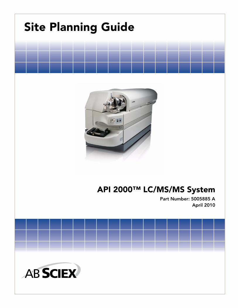
Site Planning Guide
API 2000™ LC/MS/MS SystemPart Number: 5005885 A
April 2010

This document is provided to customers who have purchased AB SCIEX equipment to use in the operation of such AB SCIEX equipment. This document is copyright protected and any reproduction of this document or any part of this document is strictly prohibited, except as AB SCIEX may authorize in writing.
Equipment that may be described in this document is protected under one or more patents filed in the United States, Canada, and other countries. Additional patents are pending.
Software that may be described in this document is furnished under a license agreement. It is against the law to copy, modify, or distribute the software on any medium, except as specifically allowed in the license agreement. Furthermore, the license agreement may prohibit the software from being disassembled, reverse engineered, or decompiled for any purpose.
Portions of this document may make reference to other manufacturers and/or their products, which may contain parts whose names are registered as trademarks and/or function as trademarks of their respective owners. Any such usage is intended only to designate those manufacturers' products as supplied by AB SCIEX for incorporation into its equipment and does not imply any right and/or license to use or permit others to use such manufacturers' and/or their product names as trademarks.
AB SCIEX makes no warranties or representations as to the fitness of this equipment for any particular purpose and assumes no responsibility or contingent liability, including indirect or consequential damages, for any use to which the purchaser may put the equipment described herein, or for any adverse circumstances arising therefrom.
For research use only. Not for use in diagnostic procedures.
The trademarks mentioned herein are the property of AB Sciex Pte. Ltd. or their respective owners.AB SCIEX™ is being used under license.
AB SCIEX
71 Four Valley Dr., Concord, Ontario, Canada. L4K 4V8.
AB SCIEX LP is ISO 9001 registered.
© 2010 AB SCIEX.
Printed in Canada.

Table of Contents
3
Table of ContentsAbout this Manual . . . . . . . . . . . . . . . . . . . . . . . . . . . . . . . . . . . . . . . . . . . . . . . . . . . . . . . 5
International Standards . . . . . . . . . . . . . . . . . . . . . . . . . . . . . . . . . . . . . . . . . . . . . . . . . . . 7Federal Communications Commission Compliance . . . . . . . . . . . . . . . . . . . . . . . . . . . . . . . 7International Compliance . . . . . . . . . . . . . . . . . . . . . . . . . . . . . . . . . . . . . . . . . . . . . . . . . . . 7
API 2000 Instrument . . . . . . . . . . . . . . . . . . . . . . . . . . . . . . . . . . . . . . . . . . . . . . . . . . . . . 9Introduction . . . . . . . . . . . . . . . . . . . . . . . . . . . . . . . . . . . . . . . . . . . . . . . . . . . . . . . . . . . . . . 9Connections . . . . . . . . . . . . . . . . . . . . . . . . . . . . . . . . . . . . . . . . . . . . . . . . . . . . . . . . . . . . . . 9
Site Responsibilities Outline . . . . . . . . . . . . . . . . . . . . . . . . . . . . . . . . . . . . . . . . . . . . . . . . . . . 11Customer Responsibilities . . . . . . . . . . . . . . . . . . . . . . . . . . . . . . . . . . . . . . . . . . . . . . . . . . 11Customer Service Representative Responsibilities . . . . . . . . . . . . . . . . . . . . . . . . . . . . . . . 12
System Requirements . . . . . . . . . . . . . . . . . . . . . . . . . . . . . . . . . . . . . . . . . . . . . . . . . . . . 13Suggested Room Layout . . . . . . . . . . . . . . . . . . . . . . . . . . . . . . . . . . . . . . . . . . . . . . . . . . . . . . 13
Room Dimensions . . . . . . . . . . . . . . . . . . . . . . . . . . . . . . . . . . . . . . . . . . . . . . . . . . . . . . . . 13Operating Environment . . . . . . . . . . . . . . . . . . . . . . . . . . . . . . . . . . . . . . . . . . . . . . . . . . . . 14Electrical Requirements. . . . . . . . . . . . . . . . . . . . . . . . . . . . . . . . . . . . . . . . . . . . . . . . . . . . 14Gas Requirements . . . . . . . . . . . . . . . . . . . . . . . . . . . . . . . . . . . . . . . . . . . . . . . . . . . . . . . . 15Exhaust Requirements . . . . . . . . . . . . . . . . . . . . . . . . . . . . . . . . . . . . . . . . . . . . . . . . . . . . . 17Computer Communications Cable Layout Requirements . . . . . . . . . . . . . . . . . . . . . . . . . . 18
Weights and Dimensions . . . . . . . . . . . . . . . . . . . . . . . . . . . . . . . . . . . . . . . . . . . . . . . . . . . . . . 19Computer Communications Cable Layout Requirements . . . . . . . . . . . . . . . . . . . . . . . . . . 19
Application Computer System Requirements . . . . . . . . . . . . . . . . . . . . . . . . . . . . . . . . . . . . . . 20Recommended Supplies . . . . . . . . . . . . . . . . . . . . . . . . . . . . . . . . . . . . . . . . . . . . . . . . . . . . . . . 21
Useful Part Numbers and Suppliers. . . . . . . . . . . . . . . . . . . . . . . . . . . . . . . . . . . . . . . . . . . 21Customer Supplied Equipment and Materials . . . . . . . . . . . . . . . . . . . . . . . . . . . . . . . . . . . . . . 22
Solvents . . . . . . . . . . . . . . . . . . . . . . . . . . . . . . . . . . . . . . . . . . . . . . . . . . . . . . . . . . . . . . . . 22Gases . . . . . . . . . . . . . . . . . . . . . . . . . . . . . . . . . . . . . . . . . . . . . . . . . . . . . . . . . . . . . . . . . . 22Electrical . . . . . . . . . . . . . . . . . . . . . . . . . . . . . . . . . . . . . . . . . . . . . . . . . . . . . . . . . . . . . . . 22Regulators . . . . . . . . . . . . . . . . . . . . . . . . . . . . . . . . . . . . . . . . . . . . . . . . . . . . . . . . . . . . . . 22Ventilation . . . . . . . . . . . . . . . . . . . . . . . . . . . . . . . . . . . . . . . . . . . . . . . . . . . . . . . . . . . . . . 22
Appendix A - Line Voltage Conditioning . . . . . . . . . . . . . . . . . . . . . . . . . . . . . . . . . . . . 25Introduction . . . . . . . . . . . . . . . . . . . . . . . . . . . . . . . . . . . . . . . . . . . . . . . . . . . . . . . . . . . . . . . . 25
Policy . . . . . . . . . . . . . . . . . . . . . . . . . . . . . . . . . . . . . . . . . . . . . . . . . . . . . . . . . . . . . . . . . . 25Line Input Circuits . . . . . . . . . . . . . . . . . . . . . . . . . . . . . . . . . . . . . . . . . . . . . . . . . . . . . . . . . . . 25
Transients. . . . . . . . . . . . . . . . . . . . . . . . . . . . . . . . . . . . . . . . . . . . . . . . . . . . . . . . . . . . . . . 25Regulation . . . . . . . . . . . . . . . . . . . . . . . . . . . . . . . . . . . . . . . . . . . . . . . . . . . . . . . . . . . . . . 25Supply Interruption . . . . . . . . . . . . . . . . . . . . . . . . . . . . . . . . . . . . . . . . . . . . . . . . . . . . . . . 25
Appendix B - Summary of Statistics . . . . . . . . . . . . . . . . . . . . . . . . . . . . . . . . . . . . . . . . 27

Table of Contents
4
Appendix C - Customer Site Setup Check-off List . . . . . . . . . . . . . . . . . . . . . . . . . . . . 29
About this Manual
5
About this ManualThis Site Planning Guide contains information intended to familiarize the customer with the necessary preparations and procedures for the installation of the API 2000 product and associated peripherals. The guide contains detailed descriptions of the requirements for laboratory layout and required customer supplies. Within the scope of this manual, the following conventions are used:
WARNING! Indicates an operation that may cause personal injury if precautions are not implemented.
CAUTION! Indicates an operation that may cause damage to the instrument if precautions are not implemented.
NOTE: Emphasizes significant information in a procedure or description.

About this Manual
6

International Standards
7
International StandardsThis instrument and its components meet or exceed the requirements of the following international agencies. Applicable labels for these qualifications have been attached to various components of the instruments.
Federal Communications Commission ComplianceThis equipment has been tested and found to comply with the limits for a Class A digital device, pursuant to Part 15 of the FCC Rules. These limits are designed to provide reasonable protection against harmful interference when the equipment is operated in a commercial environment. This equipment generates, uses, and can radiate radio frequency energy and, if not installed and used in accordance with the instruction manual, may cause harmful interference to radio communications. Operation of this equipment in a residential area is likely to cause harmful interference in which case the user will be required to correct the interference at his own expense.
International Compliance• FCC Part 15, Subpart B, Class A• EN 50082.1, EN 50093, EN 61000-3-2 and EN 61000-3-3• Class A of CISPR publication 22 (1993)/British Standard BSI EN 55022 (1987)• IEC 1000-4-2, IEC 1000-4-3, IEC 1000-4-4, IEC 1000-4-5, IEC 1000-4-6,
IEC 1000-4-8, and IEC 1000-4-11• Certificate of CE Compliance is included with the instrument

International Standards
8

API 2000 Instrument
9
API 2000 InstrumentThe API 2000 instruments, besides housing a mass spectrometer, provide connection panels for gas and pump inputs and exhaust, and electronic interfaces with the Data Acquisition System.
IntroductionThe API 2000 series of LC MS/MS instruments are Liquid Chromatography (LC) Mass Spectrometers (MS), which incorporate an Atmospheric Pressure Ionization (API) Ion Source. The diagrams below show the instrument from the front and back.
API 2000 Mass Spectrometer - Front View
API 2000 Mass Spectrometer - Rear View
ConnectionsConnections to the instrument are located on the two rear bulkheads, which are positioned on the rear corners of the instrument mass spectrometer.The Gas Connection Panel is located on the right side at the rear of the instrument (closest to the Ion Source). The following figure shows the Gas and Interface connections.

API 2000 Instrument
10
Gas Connection Panel for API 2000 Instruments
The rear bulkhead also contains the connections for the main power connection (between 207 and 242 VAC at 50/60 Hz), Applications Computer interface, and both an Auxiliary I/O port and an RS-232 interface.

API 2000 Instrument
11
Site Responsibilities Outline
Customer Responsibilities
Items the customer must supply for site set up:1. Three separately regulated gas lines with shut off valves and fittings set up to the
specifications in the Gas Requirements and Gas Regulators tables.2. Within North America: Two 15 amp circuits at 207 to 242 VAC with two NEMA 6-
15R receptacles each (4 total) located no more than 1.8 meters (6 ft) from the bench. Plugs for these receptacles must be provided by the customer and will be installed on the applicable power cords by the service representative during installation. See the Electrical Requirements section for details.Outside of North America: Two 15 amp circuits at 207 to 242 VAC with two suitable receptacles each (4 total) located no more than 1.8 meters (6 ft) from the bench. The customer must provide applicable mating plugs for each receptacle.
3. A moveable bench for the API system or a fixed bench with 1 m (3.3 ft) of rear clearance and sufficient space underneath for the mechanical roughing pump. See Suggested Room Layout section for details.
4. A bench for the computer equipment located within 3 m (10’) of the mass spectrometer.See Suggested Room Layout section for details.
5. One positive flow vent with a 3.2 cm OD smooth fitting located within 1.5 m of the roughing pump outlet, or one mist filter.
6. One positive flow vent with a 1.27 cm OD barbed fitting and sufficient 1.27 cm ID silicone tubing to connect the vent to the supplied source exhaust bottle.
7. Nitrogen gas and/or Zero Air at the pressures, quantities and qualities specified in the Gas Requirements table.
8. One (1) liter quantities of HPLC or MS grade methanol, acetonitrile and water.9. Tubing fittings required to connect any LC equipment to the API unless the
equipment was sold by AB SCIEX or was part of an AB SCIEX designed and sold workstation.
10. A one liter chemical waste bottle.
NOTE: Extra Charges will apply if the site is not set up to specification or extra parts are required.

API 2000 Instrument
12
Customer Service Representative Responsibilities
The Customer Service Representative for site set up and installation will:1. Supply all fittings, plugs, tubing and cables required to connect the API system to the
lab vents, a chemical waste bottle, electrical receptacles and regulators provided they are within the maximum distances specified in this site guide.
2. Test and qualify the API system to the specifications in the Installation Test Documents.
3. Assemble and set up any benches ordered with the instrument.4. Not supply regulators, shut off valves, electrical receptacles solvents or gases.5. Not supply LC fittings or tubing except as described in item 9 above.6. Only set up AB SCIEX supplied and manufactured LC Equipment.7. Only connect up and ensure RS-232 communications with peripheral devices unless it
is a part of a workstation.

System Requirements
13
System Requirements
Suggested Room LayoutWhile the recommendations for room layout are flexible, the recommendations regarding operating conditions should be followed as closely as possible to ensure proper and safe equipment operation.
Suggested Room Layout-Top View
Room DimensionsThe customer must provide the Customer Service Representative adequate access to the instrument. A clearance of approximately 1 m (3.3 ft) to any one side of the unit as necessary at the time of service is required. NOTE: The custom bench option is the recommended bench. Use of wall-mounted, fixed benches will require custom installation.For purposes of sound proofing, it is highly recommended that a soft wall be located behind the instrument.
System Requirements
14
Operating EnvironmentThe site environment should be kept clean and generally dust-free. High standards of cleanliness are expected.
Mass SpectrometerTo ensure the proper operating conditions for the instrument, the environmental conditions must be maintained within ±2°C in the range of 15 to 30°C with a relative humidity of between 35 and 80% non-condensing. Operation of the Instrument above 2000 m (6500 ft) above sea level is not recommended.The Basic API system air conditioning requirements are 1300 W (4400 Btu/h) for the mass spectrometer and roughing pump. The TurboIonSpray or Heated Nebulizer will add an additional heat load of 200 W (780 Btu/h).
Roughing PumpTo ensure proper operation of the roughing pump, the ambient temperature must be maintained between 10 to 45°C, with a relative humidity of 20 to 95% non-condensing.NOTE: It is important that the roughing pump not be placed in an enclosed area. Without proper ventilation, it will fail prematurely or shut down from overheating.
Electrical RequirementsTwo separate, grounded 207 to 242 VAC, single phase, 15 amp circuits with two receptacles each are recommended to supply the power requirements for the following:• API Mass Spectrometer.• Roughing pump.• National Instruments GPIB Box.• Custom Bench.In North America use 6-15R receptacles and 6-15P plugs. Outside of North America, use local standards. Each circuit must have two receptacles. Receptacles and their applicable plugs must be provided by the customer. If local voltages are outside the instrument specifications of 207 to 242 VAC, the Line Adjustment Transformer option (WC014179) must be used. If the line voltage fluctuates by more than 5% during a 24 hour period and falls out of specified values, a power conditioner may be needed.If supplied, the GPIB Box from National Instruments comes configured from the factory for 220 VAC operation. For use with 110 VAC, it is necessary to reconfigure the internal dip switches and replace the GPIB Box fuse.A minimum of three electrical outlets will be required for the computer equipment. If the PE Series 200 pump, Autosampler, UV detector and Nelson NCL 902 or equivalents are purchased, four 117 V grounded outlets will be required. Other outlets will be required for LC pumps, autosamplers, analog digital converter (ADC) boxes and ultraviolet (UV) detectors. Please consult the respective manufacturers’ documentation for specifications.
NOTE: Powerline conditioners are not recommended or specified. See Appendix A for a discussion of power conditioner requirements.
System Requirements
15
Power ConsumptionThe API 2000 instrument, including the roughing pump requires a nominal line voltage of 220 VAC (207 to 242 VAC) at 12 amps. The API mass spectrometer and roughing pump each require a nominal 220 VAC at 6 amps.
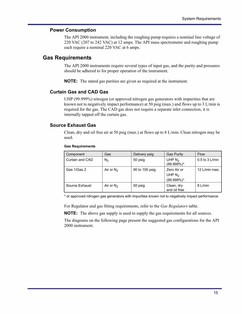
Gas RequirementsThe API 2000 instruments require several types of input gas, and the purity and pressures should be adhered to for proper operation of the instrument.
NOTE: The stated gas purities are given as required at the instrument.
Curtain Gas and CAD GasUHP (99.999%) nitrogen (or approved nitrogen gas generators with impurities that are known not to negatively impact performance) at 50 psig (max.) and flows up to 3 L/min is required for the gas. The CAD gas does not require a separate inlet connection, it is internally tapped off the curtain gas.
Source Exhaust GasClean, dry and oil free air at 50 psig (max.) at flows up to 8 L/min. Clean nitrogen may be used.
* or approved nitrogen gas generators with impurities known not to negatively impact performance
For Regulator and gas fitting requirements, refer to the Gas Regulators table.NOTE: The above gas supply is used to supply the gas requirements for all sources.The diagrams on the following page present the suggested gas configurations for the API 2000 instrument.
Gas Requirements
Component Gas Delivery psig Gas Purity FlowCurtain and CAD N2 50 psig UHP N2
(99.999%)*0.5 to 3 L/min
Gas 1/Gas 2 Air or N2 90 to 100 psig Zero Air or UHP N2(99.999%)*
12 L/min max.
Source Exhaust Air or N2 50 psig Clean, dry and oil free
8 L/min

System Requirements
16
Suggested Gas Configurations
Gas Connection Schematic Using Dewar and Separate Air
Gas Connection Schematic Using Cylinders

System Requirements
17
Gas Connection Schematic Using Dewar, Separate Air and House Air
CAUTION! The operation of API 2000 instruments require that if house gases are being supplied, each supply must be separately regulated at the instrument.
NOTE: The preferred method for gas line connections is the use of compression fittings. Liquid pipe sealant is not acceptable for gas line connections. If threaded fittings must be used, only teflon tape is acceptable for sealing the threads. Soldered fittings are not acceptable.
Exhaust RequirementsExhaust from the API 2000 instrument originates from the source exhaust and roughing pump. Refer to the warning on the following page for source exhaust safety issues.
Source Exhaust PumpDuring operation, solvent vapors are exhausted from the ion source by the source exhaust pump to a 1.27 cm (0.5 in.) barbed fitting at the rear of the instrument. These vapors pass through a trap, which must then be vented to a fume hood or outside port. The diameter of the trap exhaust port is 1.27 cm (0.5 in). The customer must provide the proper plumbing from this trap to the ventilation point.
System Requirements
18
Roughing Pump ExhaustThe customer has the option of purchasing the installation kit which includes smoke eliminators (mist filters) for the roughing pump. The system includes fittings and tubing to connect the roughing pump to the fume hood or other vents.
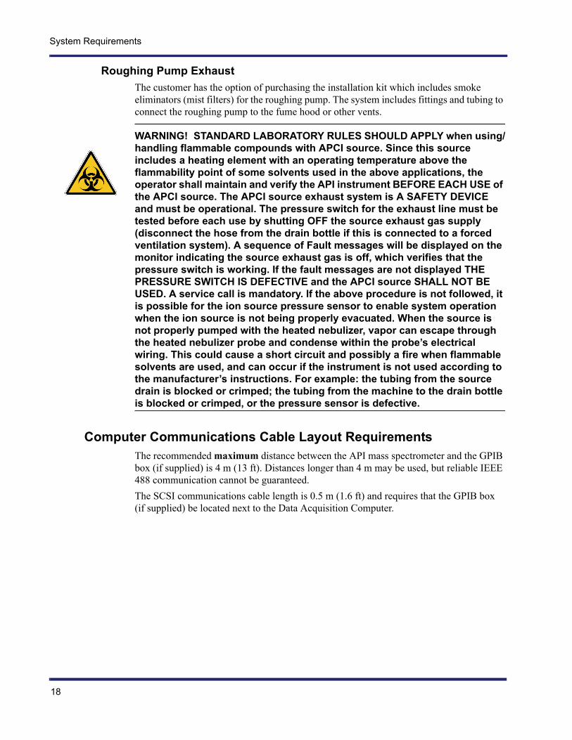
WARNING! STANDARD LABORATORY RULES SHOULD APPLY when using/handling flammable compounds with APCI source. Since this source includes a heating element with an operating temperature above the flammability point of some solvents used in the above applications, the operator shall maintain and verify the API instrument BEFORE EACH USE of the APCI source. The APCI source exhaust system is A SAFETY DEVICE and must be operational. The pressure switch for the exhaust line must be tested before each use by shutting OFF the source exhaust gas supply (disconnect the hose from the drain bottle if this is connected to a forced ventilation system). A sequence of Fault messages will be displayed on the monitor indicating the source exhaust gas is off, which verifies that the pressure switch is working. If the fault messages are not displayed THE PRESSURE SWITCH IS DEFECTIVE and the APCI source SHALL NOT BE USED. A service call is mandatory. If the above procedure is not followed, it is possible for the ion source pressure sensor to enable system operation when the ion source is not being properly evacuated. When the source is not properly pumped with the heated nebulizer, vapor can escape through the heated nebulizer probe and condense within the probe’s electrical wiring. This could cause a short circuit and possibly a fire when flammable solvents are used, and can occur if the instrument is not used according to the manufacturer’s instructions. For example: the tubing from the source drain is blocked or crimped; the tubing from the machine to the drain bottle is blocked or crimped, or the pressure sensor is defective.
Computer Communications Cable Layout RequirementsThe recommended maximum distance between the API mass spectrometer and the GPIB box (if supplied) is 4 m (13 ft). Distances longer than 4 m may be used, but reliable IEEE 488 communication cannot be guaranteed.The SCSI communications cable length is 0.5 m (1.6 ft) and requires that the GPIB box (if supplied) be located next to the Data Acquisition Computer.
System Requirements
19
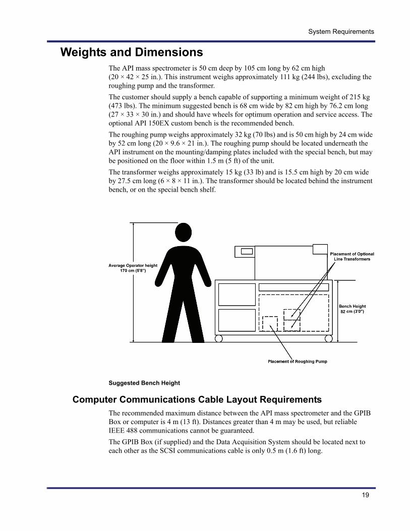
Weights and DimensionsThe API mass spectrometer is 50 cm deep by 105 cm long by 62 cm high (20 × 42 × 25 in.). This instrument weighs approximately 111 kg (244 lbs), excluding the roughing pump and the transformer.The customer should supply a bench capable of supporting a minimum weight of 215 kg (473 lbs). The minimum suggested bench is 68 cm wide by 82 cm high by 76.2 cm long (27 × 33 × 30 in.) and should have wheels for optimum operation and service access. The optional API 150EX custom bench is the recommended bench.The roughing pump weighs approximately 32 kg (70 lbs) and is 50 cm high by 24 cm wide by 52 cm long (20 × 9.6 × 21 in.). The roughing pump should be located underneath the API instrument on the mounting/damping plates included with the special bench, but may be positioned on the floor within 1.5 m (5 ft) of the unit.The transformer weighs approximately 15 kg (33 lb) and is 15.5 cm high by 20 cm wide by 27.5 cm long (6 × 8 × 11 in.). The transformer should be located behind the instrument bench, or on the special bench shelf.
Suggested Bench Height
Computer Communications Cable Layout RequirementsThe recommended maximum distance between the API mass spectrometer and the GPIB Box or computer is 4 m (13 ft). Distances greater than 4 m may be used, but reliable IEEE 488 communications cannot be guaranteed.The GPIB Box (if supplied) and the Data Acquisition System should be located next to each other as the SCSI communications cable is only 0.5 m (1.6 ft) long.

System Requirements
20
Application Computer System RequirementsOnly computers supplied by AB SCIEX are fully supported; there is no guarantee that customer-supplied computers can be made to work properly. AB SCIEX may charge customers for any additional time required to make a customer-supplied computer operable.Computer system requirements may be upgraded from time to time. Please contact your service representative for the current system requirements. Where an Ethernet network is used, the customer is responsible for establishing network connections and assigning a unique TCP/IP address to the applications computer. The Customer Service Representative will provide the customer with the information required to connect the API 2000 instrument to the Analyst computer. The customer will need to contact their Systems Administrator for the proper TCP/IP address and any required network connection hardware.
NOTE: To ensure reliable IEEE 488 communications between the Applications Computer and the API mass spectrometer, the GPIB cable length is limited to 4 m (13 ft).

System Requirements
21
Recommended SuppliesIn the suggested room layout, the LC pumps and autosamplers require a movable bench for access to the IonSpray, Heated Nebulizer, or TurboIonSpray.The Computer equipment may be placed on a fixed bench, provided that access to the API instrument is not restricted.The bench space requirements for the pump, computers, etc. is dependent on the respective manufacturer.
Useful Part Numbers and SuppliersThe following is a list of part numbers for third party supplied products and their manufacturers.
* Not recommended for Negative Ion mode of operation.
Two 1.5 m (5 ft.) lengths of exhaust gas hose and fittings are supplied with the system. Exhaust lines greater than five feet will require extra tubing and fittings. See table below for part numbers.All regulator output fittings are 1/4” NPT to 1/4” Swagelok (Swagelok P/N SS-400-11-4).
Gas Regulators
Use Regulators Manufacturer Cylinder/Dewar Gas Regulator Part No.
House Gas Regulator Part No.
Curtain Gas N2 - 50 psig Matheson (100 psig max.)
SP-3810-580(1/4” fitting)
SP-3231(1/4” fitting)
Gas 1 and Gas 2
Air - 100 psig or nitrogen*
Matheson (100 psig max.)
SP-3810-590(1/4” fitting)
SP-3231(1/4” fitting)
Source Exhaust
Air - 50 psig Matheson (100 psig max.)
SP-3810-590 (1/4” fitting)
SP-3231(1/4” fitting)
Roughing Pump Exhaust Supplies Table
Use Vacuum System Fittings Manufacturer Part No.
Roughing Pump ExhaustFilter
Smoke Eliminator (optional)
Leybold 99-171-126
Roughing Pump Exhaust Hose
As required (One 5 ft lengths supplied)
-- WC015516(AB SCIEX part no.)
Vacuum Hose Fitting One required (32 mm supplied with system)
Leybold WC007962(AB SCIEX part no.)
Screw Type Clamp Four required (supplied with system)
TRIDONHS-24
WC000249(AB SCIEX part no.)
Roughing Pump Exhaust Hose Fitting
Two required per pump (supplied with system)
-- WC015518(AB SCIEX part no.)
Regulator Fitting 3 required SwagelokSS-400-11-4

System Requirements
22
Customer Supplied Equipment and MaterialsThe customer is responsible for providing the following supplies while operating the API 2000 instruments.
SolventsThe customer will supply methanol, acetonitrile, and water (all HPLC grade).
GasesThe customer will supply the following gases:• UHP nitrogen at 50 psig, up to 3 L/min for curtain gas and CAD gas.• Zero Air or UHP nitrogen at 90 to 100 psig, up to 12 L/min for Gas 1 and Gas 2.• House Air at 50 psig to 8 L/min, clean dry and oil free for source exhaust or pump
nitrogen.
WARNING! Use qualified personnel for the installation of plumbing and fixtures, and ensure that all installations follow local bylaws and bio-hazardous regulations.
ElectricalThe customer will supply the following electrical connections:• Two grounded 220 VAC (207 to 242 VAC), single phase, 15 amp circuits with 2
NEMA 6-15R receptacles and plugs per line for the API instrument and other instrument accessories (GPIB, roughing pump and custom bench).
NOTE: The Line Adjustment Transformer option (WC014179) is the recommended means of supplying the required voltage if the 207 to 242 VAC specification cannot be met.
• Sufficient outlets for autosamplers, LC pumps, and other computer equipment. See manufacturer’s specifications for voltage, current, and other requirements.
WARNING! Use qualified personnel for the installation of all electrical fixtures, and ensure that all installations follow local by-laws.
RegulatorsCustomers must supply the appropriate gas regulators for the gas supplies. The gas regulators required for gas cylinders/dewars and house gases are listed in the Gas Regulators table.
VentilationThe customer must supply ventilation as required by local bylaws and regulations for the roughing pump and source exhaust pump.

System Requirements
23
NOTE: For installations where the optional installation kit has been purchased, (WC014543) venting of the roughing pump is not necessary as smoke eliminators have been included.
WARNING! Use qualified personnel for the installation of plumbing and fixtures, and ensure that all installations follow local bylaws and bio-hazardous regulations.
WARNING! It is strongly recommended that the source exhaust system be used and that the exhaust is safely removed from the laboratory environment.
WARNING! STANDARD LABORATORY RULES SHOULD APPLY when using/handling flammable compounds with APCI source. Since this source includes a heating element with an operating temperature above the flammability point of some solvents used in the above applications, the operator shall maintain and verify the API instrument BEFORE EACH USE of the APCI source. The APCI source exhaust system is A SAFETY DEVICE and must be operational. The pressure switch for the exhaust line must be tested before each use by shutting OFF the source exhaust gas supply (disconnect the hose from the drain bottle if this is connected to a forced ventilation system). A sequence of Fault messages will be displayed on the monitor indicating the source exhaust gas is off, which verifies that the pressure switch is working. If the fault messages are not displayed THE PRESSURE SWITCH IS DEFECTIVE and the APCI source SHALL NOT BE USED. A service call is mandatory. If the above procedure is not followed, it is possible for the ion source pressure sensor to enable system operation when the ion source is not being properly evacuated. When the source is not properly pumped with the heated nebulizer, vapor can escape through the heated nebulizer probe and condense within the probe’s electrical wiring. This could cause a short circuit and possibly a fire when flammable solvents are used. This can occur if the instrument is not used according to the manufacturer’s instructions. For example: the tubing from the source drain is blocked or crimped; the tubing from the machine to the drain bottle is blocked or crimped, or the pressure sensor is defective.

System Requirements
24

Appendix A - Line Voltage Conditioning
25
Appendix A - Line Voltage Conditioning
IntroductionLine voltage requirements for the LC/MS equipment are defined in the documentation. These requirements are not stringent and can normally be met by the local electrical supply authority.
PolicyWhere the electric supply does not meet supplied requirements, it is recommended that the customer should consult their power supplier or a local consultant on line conditioning apparatus to establish the most effective solution to the problem. See Appendix B for specifications.
Line Input Circuits
TransientsThe API 2000 Instrument has line filter circuits that should eliminate the effects of brief transients. The API 2000 Instrument is tested to IEC 1000-4.
RegulationThe electronics in this equipment operate from regulated power supplies which are not frequency sensitive. The required line voltage regulation is specified in the documentation. See Appendix B for specifications.
Supply InterruptionAn Uninterruptable Power Supply unit (UPS) is required to ensure continuous operation of the instrument in the event of a power supply interruption. A UPS normally includes a battery, a battery charger and an AC to DC inverter which can be both large and expensive. Normally, they are sized to run the instrument for approximately 10 minutes following a power failure, allowing an orderly termination of the work in progress. This type of equipment often includes control of line voltage regulation and additional transient protection.

Appendix A - Line Voltage Conditioning
26

Appendix B - Summary of Statistics
27
Appendix B - Summary of StatisticsThe following table provides statistics for the API 2000 series of instrument systems.
Electrical Requirements
Two separate grounded 220 VAC (207 to 242 VAC), 15 amp, single phase circuits for the following items:API Mass SpectrometerRoughing pumpNational instruments GPIB BoxCustom Bench
Gas Requirements
Curtain Gas/CAD Gas UHP (99.999%) nitrogen (or approved nitrogen gas generators with impurities that are known not to negatively impact performance) at a flow rate up to 3 L/min, at max. 50 psig.
Gas1 and Gas 2 Zero air or UHP (99.999%) nitrogen (or approved nitrogen gas generators with impurities that are known not to negatively impact performance) at 90 to 100 psig, delivered up to 12 L/min.
Source Exhaust Pump Filtered nitrogen or air gas supply (free from pump oil) at a flow rate up to 8 L/min at 50 psig.
Exhaust Requirements
Source Exhaust Pump During operation the vapors are exhausted from the ion source by the pump to a 1.27 cm (0.5 in.) OD barbed fitting at the rear of the instrument.
Roughing Pump Exhaust Hose and fittings are included, but you also have the choice of purchasing the installation kit which includes smoke eliminators for the roughing pump.If you vent the pump exhaust to a fume hood, or an outside source, the vent fitting size should be 3.21 cm (1.25 in.).
Communication Cable Layout Requirements
Recommended maximum distance between the API instrument mass spectrometer and the GPIB box is 4 m (13 ft).Longer distances than 4 m (13 ft) can be used, but reliable IEEE 488 communication cannot be guaranteed.
SCSI communication cable length is 0.5 m (1.6 ft) and requires that the GPIB box is located next to the applications computer.
Appendix B - Summary of Statistics
28
Weight and Dimensions
API 2000 Instrument
50 cm deep by 130 cm long by 52 cm high (20 × 52 × 20.8 in.).
Approximately 111 kg (244.2 lb).
Bench Minimum suggested bench is 68 cm wide by 76.2 cm long, and 82 cm high (27 × 30.5 × 32.3 in.).There should be optimum operation and service access.
Roughing pump The roughing pump weighs approximately 30 kg (66 lb).
The roughing pump is 52 cm long by 24 cm wide by 50 cm high (20.8 × 9.6 × 20 in.).
The pump should be located underneath the instrument on the mounting/damping plates and should be positioned within 1.5 m (4.95 yd.) of the unit.
Transformer Weighs approximately 15 kg (33 lb).
27.5 cm long by 20 cm wide, by 15.5 cm high (11 x 8 x 6.2 in.).
The autotransformer should be located behind the instrument or on a special bench shelf.

Appendix C - Customer Site Setup Check-off List
29
Appendix C - Customer Site Setup Check-off List
Customer
SPO #
CSE Name/#
Date
Requirement OK Pre-installation Action Required
Lab Space Requirements
Gas Requirements:
Oil free at 50 psig up to 8 L/min gas supply (air or N2) for the source exhaust pump
UHP (99.999%) N2 (or approved nitrogen gas generators with impurities that are known not to negatively impact performance) for the Curtain and CAD gases at 50 psig, up to 3 L/min
Zero air or UHP (99.999%) N2 (or approved nitrogen gas generators with impurities that are known not to negatively impact performance) for Gas 1 and Gas 2 at 90 to 100 psig, up to 12L/min
Environmental Requirements
API 2000 Mass SpectrometerAmbient temperature of 15°C to 30°C (stable within ±2 degrees) and relative humidity 20 to 80%, non-condensing
Roughing pumpAmbient temperature of 15°C to 30°C (stable within ±2 degrees) and relative humidity 20 to 80%, non-condensing
Safety Requirements
Gas Cylinders (if used) Mounted to meet local safety standards
Gas Delivery Lines
VentilationVent to remove effluent from plenum chamber exhaust pump
Preparation of Samples
Test SamplesKit as ordered requires refrigeration

Appendix C - Customer Site Setup Check-off List
30
Comments:
The following Sign-off is an acknowledgment that Site Preparation has been read and that the site has been prepared and set up according to specifications contained within the chapter within the limitations noted in the notations column.
Customer_____________________Title_____________Date_________
NOTE: Extra charges will apply if the site is not set up to specification or if extra parts are required.