six-axis force/torque sensor system section.pdf · 5.5.3 ctl calibration specifications ......
TRANSCRIPT

Engineered Products for Robotic ProductivityPinnacle Park • 1031 Goodworth Drive • Apex, NC 27539 • Tel: +1-919.772.0115 • Fax: +1-919.772.8259 • www.ati-ia.com • Email: [email protected]
F/T Transducer
Six-Axis Force/Torque Sensor System
Installation and Operation Manual
Document #: 9620-05-Transducer Section

F/T Transducer Installation and Operation ManualDocument #9620-05-Transducer Section-21
Pinnacle Park • 1031 Goodworth Drive • Apex, NC 27539 • Tel: 919.772.0115 • Fax: 919.772.8259 • www.ati-ia.com • Email: [email protected] 2
ForewordInformation contained in this document is the property of ATI Industrial Automation, Inc. and shall not be reproduced in whole or in part without prior written approval of ATI Industrial Automation, Inc. The information herein is subject to change without notice and should not be construed as a commitment on ATI Industrial Automation, Inc. This manual is periodically revised to reflect and incorporate changes made to the F/T system.
ATI Industrial Automation, Inc. assumes no responsibility for any errors or omissions in this document. Users’ critical evaluation is welcome to assist in the preparation of future documentation (see the What Do You Think section at the end of this manual).
Copyright © by ATI Industrial Automation, Inc., Apex, North Carolina USA. All Rights Reserved. Published in the USA.
In consideration that ATI Industrial Automation, Inc. (ATI) products are intended for use with robotic and/or automated machines, ATI does not recommend the use of its products for applications wherein failure or malfunction of an ATI component or system threatens life or makes injury probable. Anyone who uses or incorporates ATI components within any potentially life threatening system must obtain ATI’s prior consent based upon assurance to ATI that a malfunction of ATI’s component does not pose direct or indirect threat of injury or death, and (even if such consent is given) shall indemnify ATI from any claim, loss, liability, and related expenses arising from any injury or death resulting from use of ATI components.
All trademarks belong to their respective owners. Windows is registered trademarks of Microsoft Corporation.
FCC Compliance - Class A
This device complies with Part 15 of the FCC Rules. Operation is subject to the following two conditions: (1) this device may not cause harmful interference, and (2) this device must accept any interference received, including interference that may cause undesired operation.
CE Conformity
CTL TransducersThis device complies with EMC Directive 89/336/EEC and conforms to the following standards: EN50081-1:1992, EN50082-1:1992, CISPR 22:1993 (EN55022:1994), IEC 1000-4-2:1995, IEC 1000-4-3:1995, IEC 1000-4-4:1995DAQ TransducersThis device complies with EMC Directive 89/336/EEC and conforms to the following standards: EN55011:1998, ANSI C63.4:1992, EN61000-4-2:1995, EN61000-4-3:1995, EN61000-4-4:1995, EN61000-4-6:1995. Net F/T TransducersThis device complies with EMC Directive 2004/108/EC and conforms to the following standards: EN61326:1997+A1:1998+A2:2000,EN55022:1998_A1:2000+A2:2003, EN61000-4-2:1995+A1:1998+A2:2001, EN61000-4-3:2000, EN61000-4-4:2004, EN610000-4-5:1995+A1:1996, EN61000-4-6:1996+A1:2001, EN61000-4-8:1995, EN61000-4-11:2001.TWE TransducersThis device complies with EMC Directive 89/336/EEC and conforms to the following standards: EN50081-1:1992, EN50082-1:1992, CISPR 22:1993 (EN55022:1994), IEC 1000-4-2:1995, IEC 1000-4-3:1995, IEC 1000-4-4:1995
F/T Transducer Installation and Operation ManualDocument #9620-05-Transducer Section-21
Pinnacle Park • 1031 Goodworth Drive • Apex, NC 27539 • Tel: 919.772.0115 • Fax: 919.772.8259 • www.ati-ia.com • Email: [email protected] 3
NotePlease read the manual before calling customer service. Before calling, have the following information available:
1. Serial number (e.g., FT01234)
2. Transducer model (e.g., Nano17, Gamma, Theta, etc.)
3. Calibration (e.g., US-15-50, SI-65-6, etc.)
4. Accurate and complete description of the question or problem
5. Computer and software information. Operating system, PC type, drivers, application software, and other relevant information about your configuration.
If possible, be near the F/T system when calling.
How to Reach Us
Sale, Service and Information about ATI products:
ATI Industrial Automation 1031 Goodworth Drive Apex, NC 27539 USA www.ati-ia.com Tel: +1.919.772.0115 Fax: +1.919.772.8259 E-mail: [email protected]
Technical support and questions:Application Engineering Tel: +1.919.772.0115, Option 2, Option 2 Fax: +1.919.772.8259 E-mail: [email protected]

F/T Transducer Installation and Operation ManualDocument #9620-05-Transducer Section-21
Pinnacle Park • 1031 Goodworth Drive • Apex, NC 27539 • Tel: 919.772.0115 • Fax: 919.772.8259 • www.ati-ia.com • Email: [email protected] 4
Table of ContentsForeword .......................................................................................................................................... 2Glossary ......................................................................................................................................... 12
1.1 ExplanationofNotifications ....................................................................................................... 14
1.2 General Safety Guidelines .......................................................................................................... 14
1.3 Safety Precautions ...................................................................................................................... 14
1. Product Overview ................................................................................................................... 152. Installing the Transducer ....................................................................................................... 16
2.1 Transducer Environment ............................................................................................................ 16
2.2 Mounting the Transducer ........................................................................................................... 162.2.1 Interface Plate Design ...................................................................................................... 16
2.2.2 Mounting the Transducer with a Removable Mounting Adapter Plate .............................. 18
2.2.3 Mounting the Transducer with a Non-removable Adapter Plate ....................................... 20
2.3 Routing the Transducer Cable ................................................................................................... 21
3. Topics ...................................................................................................................................... 233.1 Accuracy over Temperature ....................................................................................................... 23
3.2 Tool Transformation Effects ....................................................................................................... 23
3.3 Environmental ............................................................................................................................. 24
3.4 Mux Transducer Input Filter Frequency Response ................................................................. 25
3.5 Transducer Strain Gage Saturation ........................................................................................... 25
4. TransducerSpecifications ..................................................................................................... 264.1 Notes ............................................................................................................................................ 26
4.1.1 AboutCTLCalibrationSpecifications ............................................................................... 26
4.1.2 Complex Loading Graph Description ............................................................................... 26
4.2 Nano17 Titanium ......................................................................................................................... 274.2.1 Nano17 Titanium Physical Properties .............................................................................. 27
4.2.2 CalibrationSpecifications(excludesCTLcalibrations) .................................................... 27
4.2.3 CTLCalibrationSpecifications ......................................................................................... 28
4.2.4 Analog Output .................................................................................................................. 28
4.2.5 Counts Value .................................................................................................................... 28
4.2.6 Nano17Titanium(USCalibrationComplexLoading) ....................................................... 29
4.2.7 Nano17Titanium(SICalibrationComplexLoading) ........................................................ 30
4.2.8 Nano17 Titanium Transducer Drawing ............................................................................. 31
4.3 Nano17Specifications(IncludesIP65/IP68Versions) ............................................................. 324.3.1 Nano17 Physical Properties ............................................................................................. 32
4.3.2 Nano17 IP65/IP68 Physical Properties ............................................................................ 32
4.3.3 CalibrationSpecifications(excludesCTLcalibrations) .................................................... 33
F/T Transducer Installation and Operation ManualDocument #9620-05-Transducer Section-21
Pinnacle Park • 1031 Goodworth Drive • Apex, NC 27539 • Tel: 919.772.0115 • Fax: 919.772.8259 • www.ati-ia.com • Email: [email protected] 5
4.3.4 CTLCalibrationSpecifications ......................................................................................... 34
4.3.5 Analog Output .................................................................................................................. 34
4.3.6 Counts Value .................................................................................................................... 34
4.3.7 Nano17(USCalibrationComplexLoading)(IncludesIP65/IP68) ..................................... 35
4.3.8 Nano17(SICalibrationComplexLoading)(IncludesIP65/IP68) ...................................... 36
4.3.9 Nano17-E Transducer Drawing ........................................................................................ 37
4.3.10 Nano17 IP65/IP68 Transducer with Axial Cable Exit Drawing ......................................... 38
4.3.11 Legacy Nano17 Transducer Drawing ............................................................................... 39
4.4 Nano25Specifications(IncludesIP65/IP68Versions) ............................................................. 404.4.1 Nano25 Physical Properties ............................................................................................. 40
4.4.2 Nano25 IP65/IP68 Physical Properties ............................................................................ 40
4.4.3 CalibrationSpecifications(excludesCTLcalibrations) .................................................... 41
4.4.4 CTLCalibrationSpecifications ......................................................................................... 42
4.4.5 Analog Output .................................................................................................................. 42
4.4.6 Counts Value .................................................................................................................... 42
4.4.7 Nano25(USCalibrationComplexLoading)(IncludesIP65/IP68) ..................................... 43
4.4.8 Nano25(SICalibrationComplexLoading)(IncludesIP65/IP68) ...................................... 44
4.4.9 Nano25-E Transducer Drawing ........................................................................................ 45
4.4.10 Nano25 IP65/IP68 Transducer with Axial Cable Exit Drawing ......................................... 46
4.4.11 Nano25 IP65/IP68 Transducer with Radial Cable Exit Drawing ....................................... 47
4.4.12 Legacy Nano25 Transducer Drawing ............................................................................... 48
4.5 Nano43Specifications ................................................................................................................ 494.5.1 Nano43 Physical Properties ............................................................................................. 49
4.5.2 CalibrationSpecifications(excludesCTLcalibrations) .................................................... 49
4.5.3 CTLCalibrationSpecifications ......................................................................................... 50
4.5.4 Analog Output .................................................................................................................. 50
4.5.5 Counts Value .................................................................................................................... 50
4.5.6 Nano43(USCalibrationComplexLoading) ..................................................................... 51
4.5.7 Nano43(SICalibrationComplexLoading) ....................................................................... 52
4.5.8 Nano43 Transducer Drawing ............................................................................................ 53
4.6 Mini27TitaniumSpecifications .................................................................................................. 544.6.1 Mini27 Titanium Physical Properties ................................................................................ 54
4.6.2 CalibrationSpecifications(excludesCTLcalibrations) .................................................... 54
4.6.3 CTLCalibrationSpecifications ......................................................................................... 55
4.6.4 Analog Output .................................................................................................................. 55
4.6.5 Counts Value .................................................................................................................... 55
4.6.6 Mini27Titanium(USCalibrationComplexLoading) ......................................................... 56
4.6.7 Mini27Titanium(SICalibrationComplexLoading) .......................................................... 57
4.6.8 Mini27 Titanium Transducer Drawing ............................................................................... 58

F/T Transducer Installation and Operation ManualDocument #9620-05-Transducer Section-21
Pinnacle Park • 1031 Goodworth Drive • Apex, NC 27539 • Tel: 919.772.0115 • Fax: 919.772.8259 • www.ati-ia.com • Email: [email protected] 6
4.7 Mini40Specifications(IncludesIP65/IP68Versions) ............................................................... 594.7.1 Mini40 Physical Properties ............................................................................................... 59
4.7.2 Mini40 IP65/IP68 Physical Properties .............................................................................. 59
4.7.3 CalibrationSpecifications(excludesCTLcalibrations) .................................................... 60
4.7.4 CTLCalibrationSpecifications ......................................................................................... 61
4.7.5 Analog Output .................................................................................................................. 61
4.7.6 Counts Value .................................................................................................................... 61
4.7.7 Mini40(USCalibrationComplexLoading)(IncludesIP65/IP68) ....................................... 62
4.7.8 Mini40(SICalibrationComplexLoading)(IncludesIP65/IP68) ........................................ 63
4.7.9 Mini40-E Transducer Drawing .......................................................................................... 64
4.7.10 Legacy Mini40 Transducer Drawing ................................................................................. 65
4.7.11 Mini40 IP65/IP68 Transducer Drawing ............................................................................. 66
4.8 Mini45TitaniumSpecifications .................................................................................................. 674.8.1 Mini45 Titanium Physical Properties ................................................................................ 67
4.8.2 CalibrationSpecifications(excludesCTLcalibrations) .................................................... 67
4.8.3 CTLCalibrationSpecifications ......................................................................................... 68
4.8.4 Analog Output .................................................................................................................. 68
4.8.5 Counts Value .................................................................................................................... 68
4.8.6 Mini45Titanium(USCalibrationComplexLoading) ......................................................... 69
4.8.7 Mini45Titanium(SICalibrationComplexLoading) .......................................................... 70
4.8.8 Mini45 Titanium Axial Exit Transducer Drawing ............................................................... 71
4.8.9 Mini45 Titanium Right Angle E-Exit Transducer Drawing ................................................. 72
4.9 Mini45Specifications(IncludesIP65/IP68Versions) ............................................................... 734.9.1 Mini45 Physical Properties ............................................................................................... 73
4.9.2 Mini45 IP65/IP68 Physical Properties .............................................................................. 73
4.9.3 CalibrationSpecifications(excludesCTLcalibrations) .................................................... 74
4.9.4 CTLCalibrationSpecifications ......................................................................................... 75
4.9.5 Analog Output .................................................................................................................. 75
4.9.6 Counts Value .................................................................................................................... 75
4.9.7 Mini45(USCalibrationComplexLoading)(IncludesIP65/IP68) ....................................... 76
4.9.8 Mini45(SICalibrationComplexLoading)(IncludesIP65/IP68) ........................................ 77
4.9.9 Mini45-E Transducer Drawing .......................................................................................... 78
4.9.10 Mini45-ERA Transducer Drawing ..................................................................................... 79
4.9.11 Mini45-AE Transducer Drawing ........................................................................................ 80
4.9.12 Mini45 IP65/IP68 Transducer Drawing ............................................................................. 81
4.9.13 Legacy Mini45 Transducer Drawing ................................................................................. 82
4.10 Mini58Specifications(IncludesIP60/IP65/IP68Versions) ....................................................... 834.10.1 Mini58 Physical Properties ............................................................................................... 83
F/T Transducer Installation and Operation ManualDocument #9620-05-Transducer Section-21
Pinnacle Park • 1031 Goodworth Drive • Apex, NC 27539 • Tel: 919.772.0115 • Fax: 919.772.8259 • www.ati-ia.com • Email: [email protected] 7
4.10.2 Mini58 IP60 Physical Properties ....................................................................................... 83
4.10.3 Mini58 IP65/IP68 Physical Properties .............................................................................. 84
4.10.4 CalibrationSpecifications(excludesCTLcalibrations) .................................................... 85
4.10.5 CTLCalibrationSpecifications ......................................................................................... 85
4.10.6 Analog Output .................................................................................................................. 86
4.10.7 Counts Value .................................................................................................................... 86
4.10.8 Tool Transform Factor ...................................................................................................... 86
4.10.9 Mini58(USCalibrationComplexLoading)(IncludesIP60/IP65/IP68) .............................. 87
4.10.10Mini58(SICalibrationComplexLoading)(IncludesIP60/IP65/IP68) ................................ 88
4.10.11 Mini58 Transducer Drawing .............................................................................................. 89
4.10.12 Mini58 IP60 Transducer Drawing ..................................................................................... 90
4.10.13 Mini58 IP65/IP68 Transducer Drawing ............................................................................. 91
4.11 Mini85Specifications(IncludesIP60Versions) ....................................................................... 924.11.1 Mini85 Physical Properties ............................................................................................... 92
4.11.2 CalibrationSpecifications(excludesCTLcalibrations) .................................................... 92
4.11.3 CTLCalibrationSpecifications ......................................................................................... 93
4.11.4 Analog Output .................................................................................................................. 93
4.11.5 Counts Value .................................................................................................................... 93
4.11.6 Tool Transform Factor ...................................................................................................... 94
4.11.7 Mini85(USCalibrationComplexLoading)(IncludesIP60) ............................................... 95
4.11.8 Mini85(SICalibrationComplexLoading)(IncludesIP60) ................................................. 96
4.11.9 Mini85 Transducer Drawing .............................................................................................. 97
4.11.10 Mini85-E Transducer Drawing .......................................................................................... 98
4.11.11 Mini85 IP60 Transducer with 20mm Through-Hole Drawing ............................................ 99
4.12 GammaSpecifications(IncludesIP60/IP65/IP68Versions) ................................................... 1004.12.1 Gamma Physical Properties ........................................................................................... 100
4.12.2 Gamma IP60 Physical Properties .................................................................................. 100
4.12.3 Gamma IP65 Physical Properties .................................................................................. 101
4.12.4 Gamma IP68 Physical Properties .................................................................................. 101
4.12.5 CalibrationSpecifications(excludesCTLcalibrations) .................................................. 102
4.12.6 CTLCalibrationSpecifications ....................................................................................... 103
4.12.7 Analog Output ................................................................................................................ 103
4.12.8 Counts Value .................................................................................................................. 104
4.12.9 Tool Transform Factor .................................................................................................... 104
4.12.10Gamma(USCalibrationComplexLoading)(IncludesIP60/IP65/IP68) .......................... 105
4.12.11Gamma(SICalibrationComplexLoading)(IncludesIP60/IP65/IP68) ............................ 106
4.12.12 Gamma DAQ/Net Transducer Drawing .......................................................................... 107
4.12.13 9105-T-Gamma Transducer without Mounting Adapter Drawing ................................... 108
4.12.14 Gamma Mounting Adapter Plate Drawing ...................................................................... 109

F/T Transducer Installation and Operation ManualDocument #9620-05-Transducer Section-21
Pinnacle Park • 1031 Goodworth Drive • Apex, NC 27539 • Tel: 919.772.0115 • Fax: 919.772.8259 • www.ati-ia.com • Email: [email protected] 8
4.12.15 Gamma IP60 Transducer Drawing ................................................................................. 110
4.12.16 Gamma IP65 Transducer Drawing ..................................................................................111
4.12.17 ECAT Gamma IP65 Transducer Drawing ....................................................................... 112
4.12.18 Gamma IP68 Transducer Drawing ................................................................................. 114
4.13 DeltaSpecifications(IncludesIP60/IP65/IP68Versions) ....................................................... 1154.13.1 Delta Physical Properties ............................................................................................... 115
4.13.2 Delta IP60 Physical Properties ....................................................................................... 115
4.13.3 Delta IP65 Physical Properties ....................................................................................... 116
4.13.4 Delta IP68 Physical Properties ....................................................................................... 116
4.13.5 CalibrationSpecifications(excludesCTLcalibrations) .................................................. 117
4.13.6 CTLCalibrationSpecifications ....................................................................................... 118
4.13.7 Analog Output ................................................................................................................ 118
4.13.8 Counts Value .................................................................................................................. 118
4.13.9 Delta(USCalibrationComplexLoading)(IncludesIP60/IP65/IP68) .............................. 119
4.13.10Delta(SICalibrationComplexLoading)(IncludesIP60/IP65/IP68) ................................ 120
4.13.11 Delta DAQ/Net Transducer Drawing .............................................................................. 121
4.13.12 9105-T-Delta Transducer without Mounting Adapter Drawing ........................................ 122
4.13.13 Delta Mounting Adapter Drawing .................................................................................... 123
4.13.14 Delta IP60 Transducer Drawing ..................................................................................... 124
4.13.15 ECAT Delta IP60 Transducer Drawing ........................................................................... 125
4.13.16 Delta IP65 Transducer Drawing ..................................................................................... 127
4.13.17 ECAT Delta IP65 Transducer Drawing ........................................................................... 128
4.13.18 Delta IP68 Transducer Drawing ..................................................................................... 130
4.14 ThetaSpecifications(IncludesIP60/IP65/IP68Versions) ...................................................... 1314.14.1 Theta Physical Properties .............................................................................................. 131
4.14.2 Theta IP60 Physical Properties ...................................................................................... 131
4.14.3 Theta IP65/IP68 Physical Properties .............................................................................. 132
4.14.4 CalibrationSpecifications(excludesCTLcalibrations) .................................................. 133
4.14.5 CTLCalibrationSpecifications ....................................................................................... 133
4.14.6 Analog Output ................................................................................................................ 134
4.14.7 Counts Value .................................................................................................................. 134
4.14.8 Tool Transform Factor .................................................................................................... 134
4.14.9 Theta(USCalibrationComplexLoading)(IncludesIP60/IP65/IP68) .............................. 135
4.14.10Theta(SICalibrationComplexLoading)(IncludesIP60/IP65/IP68) ............................... 136
4.14.11 Theta DAQ/Net Transducer Drawing .............................................................................. 137
4.14.12 9105-T-Theta Transducer without Mounting Adapter Drawing ....................................... 138
4.14.13 Theta Mounting Adapter Plate Drawing .......................................................................... 139
4.14.14 Theta IP60 Transducer Drawing ..................................................................................... 140
4.14.15 Theta IP65 Transducer Drawing ..................................................................................... 141
F/T Transducer Installation and Operation ManualDocument #9620-05-Transducer Section-21
Pinnacle Park • 1031 Goodworth Drive • Apex, NC 27539 • Tel: 919.772.0115 • Fax: 919.772.8259 • www.ati-ia.com • Email: [email protected] 9
4.14.16 Theta IP68 Transducer Drawing ..................................................................................... 142
4.15 Omega85Specifications(IncludesIP60/IP65/IP68Versions) ................................................ 1434.15.1 Omega85 Physical Properties ........................................................................................ 143
4.15.2 Omega85 IP65/IP68 Physical Properties ....................................................................... 143
4.15.3 CalibrationSpecifications(excludesCTLcalibrations) .................................................. 144
4.15.4 Omega85(USCalibrationComplexLoading)(IncludesIP65/IP68) ............................... 145
4.15.5 Omega85(SICalibrationComplexLoading)(IncludesIP65/IP68) ................................. 146
4.15.6 Omega85 Transducer Drawing ...................................................................................... 147
4.15.7 Omega85 IP65 Transducer Drawing .............................................................................. 148
4.15.8 Omega85 IP68 Transducer Drawing .............................................................................. 149
4.16 Omega160Specifications(IncludesIP60/IP65/IP68Versions) .............................................. 1504.16.1 Omega160 Physical Properties ...................................................................................... 150
4.16.2 Omega160IP160PhysicalProperties(IncludesECAT) ................................................ 150
4.16.3 Omega160 IP65/IP68 Physical Properties ..................................................................... 151
4.16.4 CalibrationSpecifications(excludesCTLcalibrations) .................................................. 152
4.16.5 CTLCalibrationSpecifications ....................................................................................... 152
4.16.6 Analog Output ................................................................................................................ 153
4.16.7 Counts Value .................................................................................................................. 153
4.16.8 Tool Transform Factor .................................................................................................... 153
4.16.9 Omega160(USCalibrationComplexLoading) (IncludesIP60/IP65/IP68) .............................................................................................. 154
4.16.10Omega160(SICalibrationComplexLoading) (IncludesIP60/IP65/IP68) .............................................................................................. 155
4.16.11 Omega160 Transducer without Mounting Adapter Drawing ........................................... 156
4.16.12 Omega160 Transducer with 53mm Through Hole ......................................................... 157
4.16.13 Omega160 Transducer with Mounting Adapter Drawing ................................................ 158
4.16.14 Omega160 IP60 Transducer Drawing ............................................................................ 159
4.16.15 ECAT Omega160 IP60 Transducer Drawing .................................................................. 160
4.16.16 Omega160 IP65 Transducer Drawing ............................................................................ 162
4.16.17 Omega160 IP68 Transducer Drawing ............................................................................ 163
4.17 Omega190Specifications(IncludesIP60/IP65/IP68Versions) .............................................. 1644.17.1 Omega190 Physical Properties ...................................................................................... 164
4.17.2 Omega190 IP60 Physical Properties ............................................................................. 164
4.17.3 Omega190 IP65/IP68 Physical Properties ..................................................................... 165
4.17.4 CalibrationSpecifications(excludesCTLcalibrations) .................................................. 166
4.17.5 CTLCalibrationSpecifications ....................................................................................... 166
4.17.6 Analog Output ................................................................................................................ 167
4.17.7 Counts Value .................................................................................................................. 167
4.17.8 Omega190(USCalibrationComplexLoading) (IncludesIP60/IP65/IP68) .............................................................................................. 168
F/T Transducer Installation and Operation ManualDocument #9620-05-Transducer Section-21
Pinnacle Park • 1031 Goodworth Drive • Apex, NC 27539 • Tel: 919.772.0115 • Fax: 919.772.8259 • www.ati-ia.com • Email: [email protected] 10
4.17.9 Omega190(SICalibrationComplexLoading) (IncludesIP60/IP65/IP68) .............................................................................................. 169
4.17.10 Omega190 DAQ/Net Transducer Drawing ..................................................................... 170
4.17.11 Omega190 IP60 Transducer Drawing ............................................................................ 171
4.17.12 Omega190 IP65 Transducer Drawing ............................................................................ 172
4.17.13 Omega190 IP68 Transducer Drawing ............................................................................ 173
4.18 Omega191Specifications(IncludesIP60/IP65/IP68Versions) .............................................. 1744.18.1 Omega191 Physical Properties ...................................................................................... 174
4.18.2 Omega191 IP60 Physical Properties ............................................................................. 174
4.18.3 Omega191 IP65/IP68 Physical Properties ..................................................................... 175
4.18.4 CalibrationSpecifications(excludesCTLcalibrations) .................................................. 176
4.18.5 CTLCalibrationSpecifications ....................................................................................... 176
4.18.6 Analog Output ................................................................................................................ 177
4.18.7 Counts Value .................................................................................................................. 177
4.18.8 Omega191(USCalibrationComplexLoading) (IncludesIP60/IP65/IP68) .............................................................................................. 178
4.18.9 Omega191(SICalibrationComplexLoading) (IncludesIP60/IP65/IP68) .............................................................................................. 179
4.18.10 Omega191 DAQ/Net Transducer Drawing ..................................................................... 180
4.18.11 Omega191 IP60 Transducer Drawing ............................................................................ 181
4.18.12 Omega191 IP65 Transducer Drawing ............................................................................ 182
4.18.13 Omega191 IP68 Transducer Drawing ............................................................................ 183
4.19 Omega250Specifications(IncludesIP60/IP65/IP68) .............................................................. 1844.19.1 Omega250PhysicalProperties(IncludesIP60/IP65/IP68) ............................................ 184
4.19.2 CalibrationSpecifications(excludesCTLcalibrations) .................................................. 185
4.19.3 CTLCalibrationSpecifications ....................................................................................... 185
4.19.4 Analog Output ................................................................................................................ 186
4.19.5 Counts Value .................................................................................................................. 186
4.19.6 Omega250(USCalibrationComplexLoading) (IncludesIP60/IP65/IP68) .............................................................................................. 187
4.19.7 Omega250(SICalibrationComplexLoading) (IncludesIP60/IP65/IP68) .............................................................................................. 188
4.19.8 Omega250 IP60 Transducer Drawing ............................................................................ 189
4.19.9 Omega250 IP65 Transducer Drawing ............................................................................ 190
4.19.10 Omega250 IP68 Transducer Drawing ............................................................................ 191
4.20 Omega331Specifications(IncludesIP65) .............................................................................. 1924.20.1 Omega331PhysicalProperties(IncludesIP65) ............................................................. 192
4.20.2 CalibrationSpecifications(excludesCTLcalibrations) .................................................. 193
4.20.3 CTLCalibrationSpecifications ....................................................................................... 193
4.20.4 Analog Output ................................................................................................................ 194

F/T Transducer Installation and Operation ManualDocument #9620-05-Transducer Section-21
Pinnacle Park • 1031 Goodworth Drive • Apex, NC 27539 • Tel: 919.772.0115 • Fax: 919.772.8259 • www.ati-ia.com • Email: [email protected] 11
4.20.5 Counts Value .................................................................................................................. 194
4.20.6 Omega331(USCalibrationComplexLoading)(IncludesIP65) ..................................... 195
4.20.7 Omega331(SICalibrationComplexLoading)(IncludesIP65) ...................................... 196
4.20.8 Omega331 Transducer Drawing .................................................................................... 197
4.20.9 Omega331 IP65 Transducer Drawing ............................................................................ 198
5. Advanced Topics .................................................................................................................. 1995.1 Reducing Noise ......................................................................................................................... 199
5.1.1 Mechanical Vibration ...................................................................................................... 199
5.1.2 Electrical Interference ..................................................................................................... 199
5.2 DetectingFailures(Diagnostics) ............................................................................................. 1995.2.1 Detecting Sensitivity Changes ........................................................................................ 199
5.3 Scheduled Maintenance ........................................................................................................... 1995.3.1 Periodic Inspection ......................................................................................................... 199
5.3.2 Periodic Calibration ........................................................................................................ 200
5.4 Transducer Cabling ................................................................................................................... 2005.4.1 Calibrations .................................................................................................................... 200
5.4.2 Cabling and Connectors ................................................................................................. 200
5.5 Resolution .................................................................................................................................. 200
6. Terms and Conditions of Sale ............................................................................................. 201

F/T Transducer Installation and Operation ManualDocument #9620-05-Transducer Section-21
Pinnacle Park • 1031 Goodworth Drive • Apex, NC 27539 • Tel: 919.772.0115 • Fax: 919.772.8259 • www.ati-ia.com • Email: [email protected] 12
GlossaryTerm DefinitionAccuracy SeeMeasurementUncertainty.ActiveX Component A reusable software component for the Windows applications.
Calibration The act of measuring a transducer’s raw response to loads and creating data used in converting the response to forces and torques.
CalibrationCertificateA statement that says the equipment measures correctly. These statements usually mean the equipment has been tested against national standards. The statements are produced as a result of calibration or re-calibration.
Compound Loading Any load that is not purely in one axis. Coordinate Frame See Point of Origin DAQ Data Acquisition device.
DAQ F/T An F/T Sensor System that uses industry standard data acquisition fasteners (usuallycomputercards)toconvertthetransducersignalsintodigitaldata.
DoF Degrees of Freedom. See Six Degrees of Freedom. Force The push or pull exerted on an object. FS Full-Scale F/T Force and Torque. F/T Controller The electronics that connect to mux transducers. Fxy The resultant force vector comprised of components Fx and Fy.
Full-Scale Error
A measurement of sensing error. For example, if the calibrated measurement range of a sensor is 100 Newtons and the sensor is accurate to within 1 Newton,thatsensorwillhaveaFull-ScaleErrorof1%(1%=0.01=1N/100N).
HTC
Fasteners Temperature Compensation. This is a method of improving thetemperatureperformanceoftransducers.Usuallythisreferstospantemperature compensation. Sometimes it also includes offset temperature compensation. HTC is better than STC.
Hysteresis A source of measurement error caused by the residual effects of previously applied loads.
IP60 Ingress Protection Rating “60” designates protection against dust IP65 Ingress Protection Rating “65” designates protection against water spray
IP68 Ingress Protection Rating “68” designates submergibility in fresh water, in this case, to a depth of 10 meters
LabVIEW A graphical programming environment created for data acquisition tasks by National Instruments.
Max. Single-Axis Overload Thelargestamountofloadinasingleaxis(allotheraxesareunloaded)thatthe transducer can withstand without damage.
MAP MountingAdapterPlate.Thetransducer’sMAPattachestothefixedsurfaceor robot arm.
MeasurementUncertainty Themaximumexpectederrorinmeasurements,asspecifiedonthecalibrationcertificate.
Moment When something receives a torque, we say a moment is applied to it.
Mux Short for multiplexer. F/T Controller Sensor Systems use mux electronics to interface to the transducer signals.
F/T Transducer Installation and Operation ManualDocument #9620-05-Transducer Section-21
Pinnacle Park • 1031 Goodworth Drive • Apex, NC 27539 • Tel: 919.772.0115 • Fax: 919.772.8259 • www.ati-ia.com • Email: [email protected] 13
Term Definition
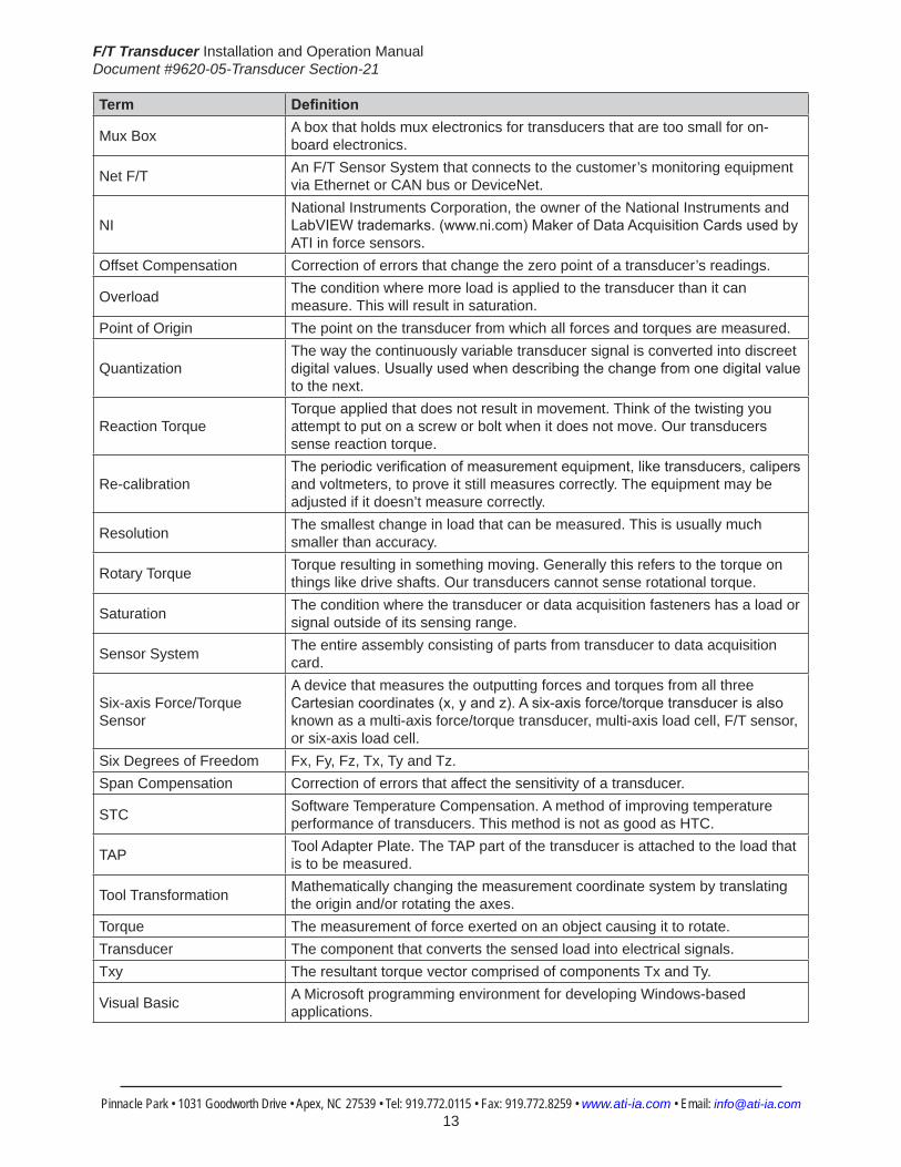
Mux Box A box that holds mux electronics for transducers that are too small for on-board electronics.
Net F/T An F/T Sensor System that connects to the customer’s monitoring equipment via Ethernet or CAN bus or DeviceNet.
NINational Instruments Corporation, the owner of the National Instruments and LabVIEWtrademarks.(www.ni.com)MakerofDataAcquisitionCardsusedbyATI in force sensors.
Offset Compensation Correction of errors that change the zero point of a transducer’s readings.
Overload The condition where more load is applied to the transducer than it can measure. This will result in saturation.
Point of Origin The point on the transducer from which all forces and torques are measured.
QuantizationThe way the continuously variable transducer signal is converted into discreet digitalvalues.Usuallyusedwhendescribingthechangefromonedigitalvalueto the next.
Reaction TorqueTorque applied that does not result in movement. Think of the twisting you attempt to put on a screw or bolt when it does not move. Our transducers sense reaction torque.
Re-calibrationTheperiodicverificationofmeasurementequipment,liketransducers,calipersand voltmeters, to prove it still measures correctly. The equipment may be adjusted if it doesn’t measure correctly.
Resolution The smallest change in load that can be measured. This is usually much smaller than accuracy.
Rotary Torque Torque resulting in something moving. Generally this refers to the torque on things like drive shafts. Our transducers cannot sense rotational torque.
Saturation The condition where the transducer or data acquisition fasteners has a load or signal outside of its sensing range.
Sensor System The entire assembly consisting of parts from transducer to data acquisition card.
Six-axis Force/Torque Sensor
A device that measures the outputting forces and torques from all three Cartesiancoordinates(x,yandz).Asix-axisforce/torquetransducerisalsoknown as a multi-axis force/torque transducer, multi-axis load cell, F/T sensor, or six-axis load cell.
Six Degrees of Freedom Fx, Fy, Fz, Tx, Ty and Tz. Span Compensation Correction of errors that affect the sensitivity of a transducer.
STC Software Temperature Compensation. A method of improving temperature performance of transducers. This method is not as good as HTC.
TAP Tool Adapter Plate. The TAP part of the transducer is attached to the load that is to be measured.
Tool Transformation Mathematically changing the measurement coordinate system by translating the origin and/or rotating the axes.
Torque The measurement of force exerted on an object causing it to rotate.Transducer The component that converts the sensed load into electrical signals. Txy The resultant torque vector comprised of components Tx and Ty.
Visual Basic A Microsoft programming environment for developing Windows-based applications.

F/T Transducer Installation and Operation ManualDocument #9620-05-Transducer Section-21
Pinnacle Park • 1031 Goodworth Drive • Apex, NC 27539 • Tel: 919.772.0115 • Fax: 919.772.8259 • www.ati-ia.com • Email: [email protected] 14
SafetyThe safety section describes general safety guidelines to be followed with this product, explanation of the notification found in this manual, and safety precaution that apply to the product. More specific notification are imbedded within the sections of the manual where they apply.
1.1 ExplanationofNotificationsThe notifications included here are specific to the product(s) covered by this manual. It is expected that the user heed all notifications from the robot manufacturer and/or the manufacturers of other components used in the installation.
DANGER:Notificationofinformationorinstructionsthatifnotfollowedwillresultindeathorseriousinjury.Thenotificationprovidesinformationaboutthenatureofthehazardous situation, the consequences of not avoiding the hazard, and the method for avoiding the situation.
WARNING:Notificationofinformationorinstructionsthatifnotfollowedcouldresultindeathorseriousinjury.Thenotificationprovidesinformationaboutthenatureofthehazardous situation, the consequences of not avoiding the hazard, and the method for avoiding the situation.
CAUTION:Notificationofinformationorinstructionsthatifnotfollowedcouldresultinmoderateinjuryorwillcausedamagetoequipment.Thenotificationprovidesinformation about the nature of the hazardous situation, the consequences of not avoiding the hazard, and the method for avoiding the situation.
NOTICE:Notificationofspecificinformationorinstructionsaboutmaintaining,operating,installation, or setup of the product that if not followed could result in damage to equipment. The notificationcanemphasizebutisnotlimitedtospecificgreasetypes,goodoperatingpractices,or maintenance tips.
1.2 General Safety GuidelinesThe customer should verify that the transducer selected is rated for maximum loads and moments expected during operation. Refer to transducer specifications in Section 5—Transducer Specifications of this manual or contact ATI for assistance. Particular attention should be paid to dynamic loads caused by robot acceleration and deceleration. These forces can be many times the value of static forces in high acceleration or deceleration situations.
1.3 Safety PrecautionsCAUTION: Do not remove any fasteners or disassemble transducers without a removable mounting adapter plate. These include Nano, Mini, IP-rated, and some Omega transducers. This will cause irreparable damage to the transducer and void the warranty. Leave all fasteners in place and do not disassemble the transducer.
CAUTION: Do not probe any openings in the transducer. This will damage the instrumentation.
CAUTION: Do not exert excessive force on the transducer. The transducer is a sensitive instrument and can be damaged by applying force exceeding the single-axis overload values of the transducer and cause irreparable damage. Small Nano and Mini transducers can easily be overloaded during installation. Refer to the F/T Transducer manual(9620-05-TransducerSection)forspecifictransduceroverloadvalues.

F/T Transducer Installation and Operation ManualDocument #9620-05-Transducer Section-21
Pinnacle Park • 1031 Goodworth Drive • Apex, NC 27539 • Tel: 919.772.0115 • Fax: 919.772.8259 • www.ati-ia.com • Email: [email protected] 15
1. Product OverviewA transducer is a device that measures the outputting forces and torques from all three Cartesian coordinates (x, y, and z). A six-axis force/torque transducer is also known as a multi-axis force/torque transducer, multi-axis load cell, F/T sensor, or six-axis load cell.
The ATI Multi-Axis Force/Torque Sensor system measures all six components of force and torque. The system consists of a transducer, shielded high-flex cable, and intelligent data acquisition system (Ethernet/DeviceNet interface or F/T controller). Force/Torque sensors are used throughout industry for product testing, robotic assembly, grinding, and polishing. In research, our sensors are used in robotic surgery, haptics, rehabilitation, neurology, and many others applications.
F/T Transducer Installation and Operation ManualDocument #9620-05-Transducer Section-21
Pinnacle Park • 1031 Goodworth Drive • Apex, NC 27539 • Tel: 919.772.0115 • Fax: 919.772.8259 • www.ati-ia.com • Email: [email protected] 16
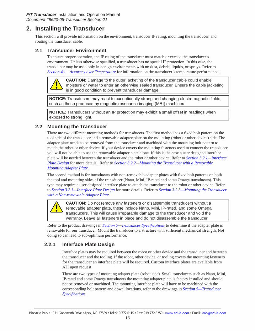
2. Installing the TransducerThis section will provide information on the environment, transducer IP rating, mounting the transducer, and routing the transducer cable.
2.1 Transducer EnvironmentTo ensure proper operation, the IP rating of the transducer must match or exceed the transducer’s environment. Unless otherwise specified, a transducer has no special IP protection. In this case, the transducer may be used only in benign environments with no dust, debris, liquids, or sprays. Refer to Section 4.1—Accuracy over Temperature for information on the transducer’s temperature performance.
CAUTION: Damage to the outer jacketing of the transducer cable could enable moisture or water to enter an otherwise sealed transducer. Ensure the cable jacketing is in good condition to prevent transducer damage.
NOTICE:Transducersmayreacttoexceptionallystrongandchangingelectromagneticfields,suchasthoseproducedbymagneticresonanceimaging(MRI)machines.
NOTICE: Transducers without an IP protection may exhibit a small offset in readings when exposed to strong light.
2.2 Mounting the TransducerThere are two different mounting methods for transducers. The first method has a fixed bolt pattern on the tool side of the transducer and a removable adapter plate on the mounting (robot or other device) side. The adapter plate needs to be removed from the transducer and machined with the mounting bolt pattern to match the robot or other device. If your device covers the mounting fasteners used to connect the transducer, you will not be able to use the removable adapter plate alone. If this is the case a user designed interface plate will be needed between the transducer and the robot or other device. Refer to Section 3.2.1—Interface Plate Design for more details.. Refer to Section 3.2.2—Mounting the Transducer with a Removable Mounting Adapter Plate.The second method is for transducers with non-removable adapter plates with fixed bolt patterns on both the tool and mounting sides of the transducer (Nano, Mini, IP-rated and some Omega transducers). This type may require a user designed interface plate to attach the transducer to the robot or other device. Refer to Section 3.2.1—Interface Plate Design for more details. Refer to Section 3.2.3—Mounting the Transducer with a Non-removable Adapter Plate.
CAUTION: Do not remove any fasteners or disassemble transducers without a removable adapter plate, these include Nano, Mini, IP-rated, and some Omega transducers. This will cause irreparable damage to the transducer and void the warranty. Leave all fasteners in place and do not disassemble the transducer.
Refer to the product drawings in Section 5—Transducer Specifications to determine if the adapter plate is removable for our transducer. Mount the transducer to a structure with sufficient mechanical strength. Not doing so can lead to sub-optimum performance.
2.2.1 Interface Plate DesignInterface plates may be required between the robot or other device and the transducer and between the transducer and the tooling. If the robot, other device, or tooling covers the mounting fasteners for the transducer an interface plate will be required. Custom interface plates are available from ATI upon request.There are two types of mounting adapter plate (robot side). Small transducers such as Nano, Mini, IP-rated and some Omega transducers the mounting adapter plate is factory installed and should not be removed or machined. The mounting interface plate will have to be machined with the corresponding bolt pattern and dowel locations, refer to the drawings in Section 5—Transducer Specifications.

F/T Transducer Installation and Operation ManualDocument #9620-05-Transducer Section-21
Pinnacle Park • 1031 Goodworth Drive • Apex, NC 27539 • Tel: 919.772.0115 • Fax: 919.772.8259 • www.ati-ia.com • Email: [email protected] 17
Larger transducers have a removable mounting adapter plates, refer to Section 3.2.2—Mounting the Transducer with a Removable Mounting Adapter Plate for more information. Machine the mounting interface plate to match the bolt pattern and dowel hole in the removable mounting adapter plate.The transducer tooling adapter plate is factory installed and the bolt circle is shown with the transducer in Section 5—Transducer Specifications. Most large F/T tool adapters follow the ISO 9409-1 mounting pattern. Machine the tooling interface plate to attach to this bolt circle.
NOTICE: The tool may not contact any other part of the transducer except the tool mounting surface. If the tool contacts any other part of the transducer it will not properly sense loads. Make sure the tool mounts to the tool mounting surface and does not contact any other part of the transducer.
If the customer chooses to design and build an mounting or tooling interface plate, the following should be considered:• The interface plate should be designed to include bolt holes for mounting, dowel pins, and
a boss for accurate positioning on the robot or other devices and to the adapter plate. These locating features should orient the X and Y axis of the Transducer to the X and Y axis of the robot.
• The thickness of the interface plate must be great enough to provide the necessary thread engagement for the mounting fasteners.
• Mounting fasteners must not be too long. They should not extend through the adapter plate to avoid interference with the electronics inside the transducer. Refer to Section 5—Transducer Specifications for thread depth, mounting patterns, and other details.
• The interface plate must be properly designed to provide rigid mounting for the transducer. The interface plate should not distort under maximum sensor range of the transducer. Refer to Section 5—Transducer Specifications for specifications.
• The interface plate design must provide a flat and parallel mounting surface for the transducer. Refer to Figure 3.1.
Figure 2.1—InterfacePlateDesignSpecification
Robot or Other Device
Locating Boss
Customer Designed Mounting Interface Plate
Customer Supplied FastenersDo not extend through Mounting Adapter Plate
TransducerTransducer Mounting
Adapter Plate
Locating Dowel Pin
Transducer Tooling Adapter Plate
Customer Supplied FastenersDo not extend through Tooling Adapter Plate
Customer Designed Tooling Interface Plate
Locating Boss
Locating Boss
Locating Dowel Pin
Tooling
.002
.002 A
.002 A
.002
A
A

F/T Transducer Installation and Operation ManualDocument #9620-05-Transducer Section-21
Pinnacle Park • 1031 Goodworth Drive • Apex, NC 27539 • Tel: 919.772.0115 • Fax: 919.772.8259 • www.ati-ia.com • Email: [email protected] 18
2.2.2 Mounting the Transducer with a Removable Mounting Adapter PlateCheck to see if when mounting the transducer to the robot or other device you will have access to the mounting screws for attaching the transducer. If not, a user designed interface plate will be needed on one or both sides of the transducer, refer to Section 3.2.1—Interface Plate Design for details in designing an interface plate before continuing with this procedure.
1. Remove the power to the transducer.2. Remove all mounting fasteners from the mounting adapter plate and set aside.
CAUTION: Do not touch internal electronics or instrumentation. This could damage the transducer and void the warranty. When the adapter plate is removed protect the exposed electronics from dust, debris, liquids, and other foreign objects.
3. Remove the adapter plate from the transducer. Machine the mounting bolt pattern from the robot, interface plate, or other device into the removable adapter plate. Make sure the bolt pattern and dowel hole orient the X and Y axis of the transducer with the X and Y axis of the robot.
NOTICE: Customers machining their own interface patterns should avoid concentrating all mounting features in the center of the adapter plate. A larger bolt circle will provide the most accurate readings as it will induce less bending in the plate.
CAUTION: Mounting fasteners should not extend into the transducer beyond the adapter plate surface. This could cause damage to the internal electronics. When machining the removable adapter plate, make sure the heads of the fastenersareflushorbelowthesurfaceoftheadapterplate.
Figure 2.2—Removable Adapter Plate
Remove Mounting AdapterPlate from Transducer
CAUTION: Do not touch internal electronics or instrumentation. This could damage the transducer and void the warranty.
Protect exposed electronics from dust, debris and liquids
Remove adapter
Machine mounting bolt pattern and locating dowel hole into mounting adapter plate. Orient
the bolt pattern and dowel hole to align the X and Y axis of the transducer with the X and Y
axis of the robot, tooling, or application orientation as desired.
User supplied mounting screws must be flush or below the surface of the mounting
adapter plate to ensure proper clearance for the electronics inside the transducer.
Machine mounting bolt pattern concentric to mountingadapter plate to maintain transducer's point-of-origin.
plate fasteners
4. Mount removable adapter plate to the robot, other device, or interface plate using customer supplied fasteners. If fasteners do not have pre-applied adhesive, apply Loctite 222® to the fasteners.
NOTICE: Make sure the adapter plate orients the transducer so that the connector is at the appropriate location to route the cabling properly. Refer to Section 3.3—Routing the Transducer Cable.
5. Attach the transducer to the removable adapter plate, hand tighten fasteners.
F/T Transducer Installation and Operation ManualDocument #9620-05-Transducer Section-21
Pinnacle Park • 1031 Goodworth Drive • Apex, NC 27539 • Tel: 919.772.0115 • Fax: 919.772.8259 • www.ati-ia.com • Email: [email protected] 19
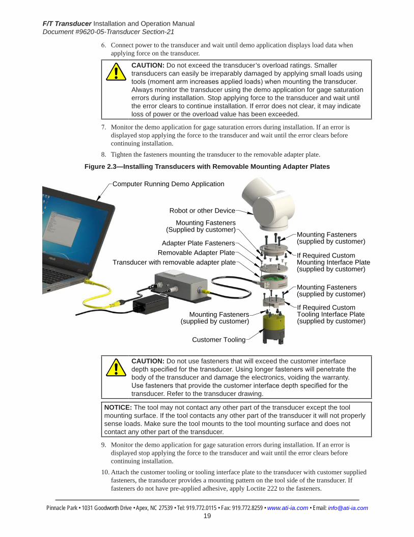
6. Connect power to the transducer and wait until demo application displays load data when applying force on the transducer.
CAUTION: Do not exceed the transducer’s overload ratings. Smaller transducers can easily be irreparably damaged by applying small loads using tools(momentarmincreasesappliedloads)whenmountingthetransducer.Always monitor the transducer using the demo application for gage saturation errors during installation. Stop applying force to the transducer and wait until the error clears to continue installation. If error does not clear, it may indicate loss of power or the overload value has been exceeded.
7. Monitor the demo application for gage saturation errors during installation. If an error is displayed stop applying the force to the transducer and wait until the error clears before continuing installation.
8. Tighten the fasteners mounting the transducer to the removable adapter plate.
Figure 2.3—Installing Transducers with Removable Mounting Adapter Plates
Adapter Plate FastenersRemovable Adapter Plate
Mounting Fasteners (Supplied by customer)
Mounting Fasteners (supplied by customer)
Customer Tooling
Computer Running Demo Application
Robot or other Device
Transducer with removable adapter plate
If Required Custom Tooling Interface Plate(supplied by customer)
Mounting Fasteners(supplied by customer)
Mounting Fasteners(supplied by customer)
If Required Custom Mounting Interface Plate(supplied by customer)
CAUTION: Do not use fasteners that will exceed the customer interface depthspecifiedforthetransducer.Usinglongerfastenerswillpenetratethebody of the transducer and damage the electronics, voiding the warranty. Usefastenersthatprovidethecustomerinterfacedepthspecifiedforthetransducer. Refer to the transducer drawing.
NOTICE: The tool may not contact any other part of the transducer except the tool mounting surface. If the tool contacts any other part of the transducer it will not properly sense loads. Make sure the tool mounts to the tool mounting surface and does not contact any other part of the transducer.
9. Monitor the demo application for gage saturation errors during installation. If an error is displayed stop applying the force to the transducer and wait until the error clears before continuing installation.
10. Attach the customer tooling or tooling interface plate to the transducer with customer supplied fasteners, the transducer provides a mounting pattern on the tool side of the transducer. If fasteners do not have pre-applied adhesive, apply Loctite 222 to the fasteners.
F/T Transducer Installation and Operation ManualDocument #9620-05-Transducer Section-21
Pinnacle Park • 1031 Goodworth Drive • Apex, NC 27539 • Tel: 919.772.0115 • Fax: 919.772.8259 • www.ati-ia.com • Email: [email protected] 20
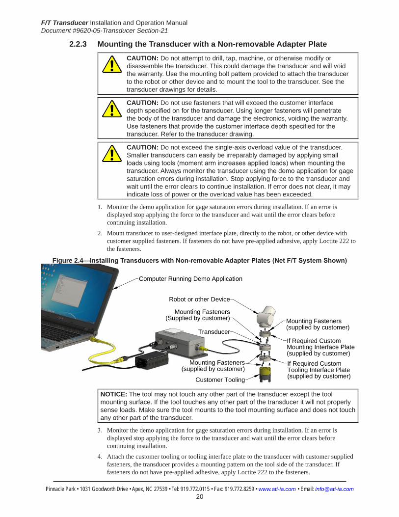
2.2.3 Mounting the Transducer with a Non-removable Adapter Plate
CAUTION: Do not attempt to drill, tap, machine, or otherwise modify or disassemble the transducer. This could damage the transducer and will void thewarranty.Usethemountingboltpatternprovidedtoattachthetransducerto the robot or other device and to mount the tool to the transducer. See the transducer drawings for details.
CAUTION: Do not use fasteners that will exceed the customer interface depthspecifiedonforthetransducer.Usinglongerfastenerswillpenetratethe body of the transducer and damage the electronics, voiding the warranty. Usefastenersthatprovidethecustomerinterfacedepthspecifiedforthetransducer. Refer to the transducer drawing.
CAUTION: Do not exceed the single-axis overload value of the transducer. Smaller transducers can easily be irreparably damaged by applying small loadsusingtools(momentarmincreasesappliedloads)whenmountingthetransducer. Always monitor the transducer using the demo application for gage saturation errors during installation. Stop applying force to the transducer and wait until the error clears to continue installation. If error does not clear, it may indicate loss of power or the overload value has been exceeded.
1. Monitor the demo application for gage saturation errors during installation. If an error is displayed stop applying the force to the transducer and wait until the error clears before continuing installation.
2. Mount transducer to user-designed interface plate, directly to the robot, or other device with customer supplied fasteners. If fasteners do not have pre-applied adhesive, apply Loctite 222 to the fasteners.
Figure 2.4—InstallingTransducerswithNon-removableAdapterPlates(NetF/TSystemShown)
Mounting Fasteners (Supplied by customer)
Mounting Fasteners (supplied by customer)
Customer Tooling
Computer Running Demo Application
Robot or other Device
Transducer
If Required Custom Tooling Interface Plate(supplied by customer)
Mounting Fasteners(supplied by customer)
If Required Custom Mounting Interface Plate(supplied by customer)
NOTICE: The tool may not touch any other part of the transducer except the tool mounting surface. If the tool touches any other part of the transducer it will not properly sense loads. Make sure the tool mounts to the tool mounting surface and does not touch any other part of the transducer.
3. Monitor the demo application for gage saturation errors during installation. If an error is displayed stop applying the force to the transducer and wait until the error clears before continuing installation.
4. Attach the customer tooling or tooling interface plate to the transducer with customer supplied fasteners, the transducer provides a mounting pattern on the tool side of the transducer. If fasteners do not have pre-applied adhesive, apply Loctite 222 to the fasteners.
F/T Transducer Installation and Operation ManualDocument #9620-05-Transducer Section-21
Pinnacle Park • 1031 Goodworth Drive • Apex, NC 27539 • Tel: 919.772.0115 • Fax: 919.772.8259 • www.ati-ia.com • Email: [email protected] 21
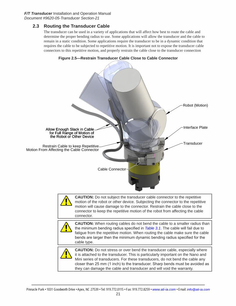
2.3 Routing the Transducer CableThe transducer can be used in a variety of applications that will affect how best to route the cable and determine the proper bending radius to use. Some applications will allow the transducer and the cable to remain in a static condition. Some applications require the transducer to be in a dynamic condition that requires the cable to be subjected to repetitive motion. It is important not to expose the transducer cable connectors to this repetitive motion, and properly restrain the cable close to the transducer connection
Figure 2.5—Restrain Transducer Cable Close to Cable Connector
Transducer
Cable Connector
Restrain Cable to keep Repetitive Motion From Affecting the Cable Connector
Allow Enough Slack in Cable for Full Range of Motion of the Robot or Other Device
Interface Plate
Robot (Motion)
Allow Enough Slack in Cable for Full Range of Motion of the Robot or Other Device
CAUTION: Do not subject the transducer cable connector to the repetitive motion of the robot or other device. Subjecting the connector to the repetitive motion will cause damage to the connector. Restrain the cable close to the connector to keep the repetitive motion of the robot from affecting the cable connector.
CAUTION: When routing cables do not bend the cable to a smaller radius than theminimumbendingradiusspecifiedinTable 3.1. The cable will fail due to fatigue from the repetitive motion. When routing the cable make sure the cable bendsarelargerthentheminimumdynamicbendingradiusspecifiedforthecable type.
CAUTION: Do not stress or over bend the transducer cable, especially where it is attached to the transducer. This is particularly important on the Nano and Mini series of transducers. For these transducers, do not bend the cable any closerthan25mm(1inch)tothetransducer.Sharpbendsmustbeavoidedasthey can damage the cable and transducer and will void the warranty.

F/T Transducer Installation and Operation ManualDocument #9620-05-Transducer Section-21
Pinnacle Park • 1031 Goodworth Drive • Apex, NC 27539 • Tel: 919.772.0115 • Fax: 919.772.8259 • www.ati-ia.com • Email: [email protected] 22
Figure 2.6—Transducer Bending Radius
25
To protect connector from repetitive motion, restrain
cable at connector end
To protect cable connection from repetitive motion, restrain cable at transducer end
(1 inch)
For Nano and Mini series TransducersDo not bend the cable any closer than 25mm (1 inch) to the transducer
Refer to Table 3.1 for minimum dynamic (cycled) bending
radius (at room temperature)
Refer to Table 3.1 for minimum static bending radius
(at room temperature)
Refer to Table 3.1 for minimum dynamic (cycled) bending radius (at room temperature)
Refer to Table 3.1 for minimum static bending radius (at room temperature)
Table 2.1—Transducer Cable Bending Radius
Cable Type Cable Dia.(mm)
Static Bending Radius(atroomtemperature)
Dynamic Bending Radius(atroomtemperature)
mm inch mm inch9105-TW 3.2 16 0.63 32 1.269105-C3 4.4 22 0.87 44 1.739105-CM 4.4 22 0.87 44 1.739105-CW 4.4 22 0.87 44 1.739105-CT 6.1 30.5 1.20 61 2.40
9105-C
3.2 16 0.63 32 1.264.4 22 0.87 44 1.736.1 30.5 1.20 61 2.40
10.0 50 1.97 100 3.949105-C-MTR 8.4 42 1.65 84 3.319105-C-MTS 8.4 42 1.65 84 3.31
9105-CF-MTR9105-CF-MTS 8.5 42.5 1.67 85 3.35
Note:Temperaturewillaffectcableflexibility.ATIrecommendsincreasingtheminimumdynamicbendingradiusforlower temperatures.
The transducer cable must be routed so that it is not stressed, pulled, kinked, cut, or otherwise damaged throughout the full range of motion. See the accompanying system manual for the transducer cable interfacing. If the desired application results in the cable rubbing, then use a loose plastic spiral wrap for protection.
CAUTION: Be careful not to crush the cable by over tightening tie wraps or walking on the cable, since this may damage the cable.
CAUTION: Cables on the Nano and Mini transducers are permanently attached to the transducer and cannot be disconnected. Do not attempt to disassemble these transducers, this will damage the transducer and void the warranty. Do not attempt to replace the cable. Contact ATI service for assistance.
CAUTION: Nano and Mini integral cables and cables of the 9105-C-H type must not subjectthetransducerendconnectiontomorethan10lbf(45N)ofside-to-sideorpullforce or permanent damage will result.
CAUTION: Larger transducers have removable cables. Do not attempt to disconnect these transducer cables by pulling on the cable itself or the connector boot; this can damage your system.

F/T Transducer Installation and Operation ManualDocument #9620-05-Transducer Section-21
Pinnacle Park • 1031 Goodworth Drive • Apex, NC 27539 • Tel: 919.772.0115 • Fax: 919.772.8259 • www.ati-ia.com • Email: [email protected] 23
3. Topics3.1 Accuracy over Temperature
Typical gain errors introduced over temperature for F/T transducers with fasteners temperature compensation are listed below. These changes in sensitivity are independent of the transducer’s rated accuracy at room temperature; the two accuracy ratings must be added to find an overall estimated accuracy at a certain temperature. This overall accuracy assumes that the unloaded and loaded measurements were taken at the same temperature. Drift error over temperature is not compensated and varies with each transducer. For best results, a reference reading should be taken or bias function executed at the current temperature before applying the load of interest.
Table 3.1—Error Introduced Over Temperature for Non-Gamma TransducersDeviation from 22°C Typical Gain Error
± 5°C 0.1%
± 15°C 0.5%
± 25°C1 1%
± 50°C1 5%Note:
1. Deviation is bounded by transducer operational limits in Section 4.3—Environmental.
Table 3.2—Error Introduced Over Temperature for Gamma Transducers Deviation from 22°C Typical Gain Error
± 5°C 0.1%
± 15°C 0.5%
± 25°C1 1.5%
± 50°C1 7%Note:
1. Deviation is bounded by transducer operational limits in Section 4.3—Environmental
3.2 Tool Transformation EffectsAll transducer working specifications pertain to the factory point-of-origin only. This includes the transducer’s range, resolution, and accuracy. The transducer working specifications at a customer-applied point-of-origin will differ from those at the factory point-of-origin.

F/T Transducer Installation and Operation ManualDocument #9620-05-Transducer Section-21
Pinnacle Park • 1031 Goodworth Drive • Apex, NC 27539 • Tel: 919.772.0115 • Fax: 919.772.8259 • www.ati-ia.com • Email: [email protected] 24
3.3 EnvironmentalThe F/T system is designed to be used in standard laboratory or light-manufacturing conditions. Transducers with an IP60 designation are able to withstand dusty environments, those with an IP65 designation are able to withstand dusty environments and wash down, and those with an IP68 designation are able to withstand dusty environments and fresh-water immersion to a specified depth. Transducers without IP65 or IP68 designation may be used in environments with up to 95% relative humidity, non-condensing.
Table 3.3—Transducer Temperature Ranges - Non-IP-RatedTransducer Model Series Storage Operation Units
9105-TIF Transducer -25 to +85 -25 to +85 °C
9105-TW Transducer -40 to +100 -40 to +100 °C
9105-TW-…-H Transducer -25 to +85 -25 to +85 °C
9105-T Transducer -20 to +80 0 to +70 °C
9105-NET Transducer -40 to +85 -40 to +85 °CNote: These temperature ranges specify the storage and operation ranges in which the transducer can survive
without damage. They do not take accuracy into account.
Table 3.4—TransducerTemperatureRanges-IP60,IP65,andIP68Transducer Model Series Storage Operation Units
9105-TIF Transducer -5 to +75 0 to +60 °C
9105-TW Transducer -5 to +105 -5 to +105 °C
9105-T Transducer -5 to +105 0 to +70 °C
9105-NET Transducer -65 to +150 0 to +70 °CNote: These temperature ranges specify the storage and operation ranges in which the transducer can survive
without damage. They do not take accuracy into account.
F/T Transducer Installation and Operation ManualDocument #9620-05-Transducer Section-21
Pinnacle Park • 1031 Goodworth Drive • Apex, NC 27539 • Tel: 919.772.0115 • Fax: 919.772.8259 • www.ati-ia.com • Email: [email protected] 25
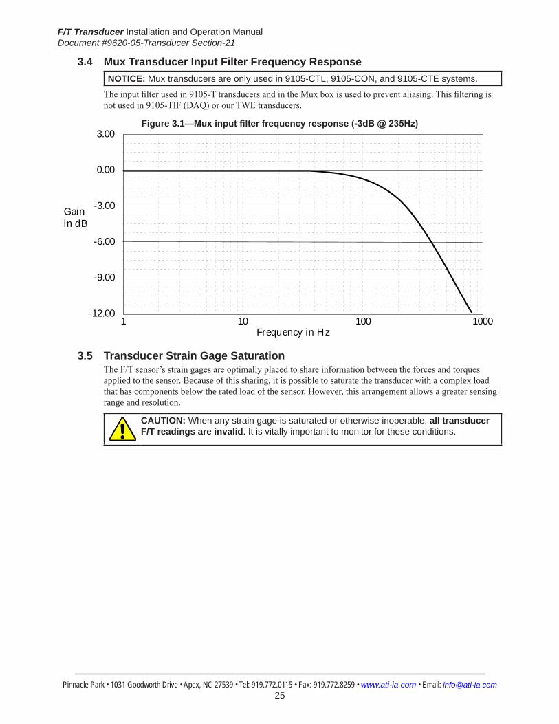
3.4 Mux Transducer Input Filter Frequency Response NOTICE: Mux transducers are only used in 9105-CTL, 9105-CON, and 9105-CTE systems.
The input filter used in 9105-T transducers and in the Mux box is used to prevent aliasing. This filtering is not used in 9105-TIF (DAQ) or our TWE transducers.
Figure 3.1—Muxinputfilterfrequencyresponse(-3dB@235Hz) 3.00
0.00
-3.00
-6.00
-9.00
-12.001 10 100 1000
Gainin dB
Frequency in Hz
3.5 Transducer Strain Gage SaturationThe F/T sensor’s strain gages are optimally placed to share information between the forces and torques applied to the sensor. Because of this sharing, it is possible to saturate the transducer with a complex load that has components below the rated load of the sensor. However, this arrangement allows a greater sensing range and resolution.
CAUTION: When any strain gage is saturated or otherwise inoperable, all transducer F/T readings are invalid. It is vitally important to monitor for these conditions.

F/T Transducer Installation and Operation ManualDocument #9620-05-Transducer Section-21
Pinnacle Park • 1031 Goodworth Drive • Apex, NC 27539 • Tel: 919.772.0115 • Fax: 919.772.8259 • www.ati-ia.com • Email: [email protected] 26
4. TransducerSpecifications4.1 Notes
4.1.1 AboutCTLCalibrationSpecificationsCTL refers to F/T systems that use the F/T Controller. Transducers used in these systems either have a 9105-T-x model transducer or include a Mux Box. The output resolution of CTL systems is different from other systems. CTL systems also provide analog voltage outputs that represent each of the six axes. CTL transducers have their own calibration specification listings because of these differences.
4.1.2 Complex Loading Graph DescriptionThe graphs in the sections for each transducer may be used to estimate a sensor’s range under complex loading. Each page represents one sensor body with either English or Metric units. The top graph represents combinations of forces in the X and/or Y directions with torques about the Z-axis. The bottom graph represents combinations of Z-axis forces with X- and/or Y-axis torques. The graphs contain several different calibrations, distinguished by line weight.The sample graph shown in Figure 5.1 shows how operating ranges can change with complex loading. The labels indicate the following regions:A. Normal operating region. You can expect to achieve rated accuracy in this region.B. Saturation region. Any load in this region will report a gage saturation condition.C. Extended operating region. In this region, the sensor will operate correctly but the
full-scale accuracy is not guaranteed.
Figure 4.1—Complex Loading Sample Graph
Tz
Fxy
C
C
B
A

F/T Transducer Installation and Operation ManualDocument #9620-05-Transducer Section-21
Pinnacle Park • 1031 Goodworth Drive • Apex, NC 27539 • Tel: 919.772.0115 • Fax: 919.772.8259 • www.ati-ia.com • Email: [email protected] 27
4.2 Nano17 Titanium4.2.1 Nano17 Titanium Physical Properties
Table 4.1—Nano17 Titanium Physical PropertiesSingle-Axis Overload (US)StandardUnits (SI)MetricUnitsFxy ±35 lbf ±160 NFz ±70 lbf ±310 NTxy ±8.9 inf-lb ±1 NmTz ±10 inf-lb ±1.2 NmStiffness(Calculated) X-axis&Y-axisforces(Kx,Ky) 2.7x10⁴ lb/in 4.8x10⁶ N/m Z-axisforce(Kz) 3.8x10⁴ lb/in 6.6x10⁶ N/m X-axis&Y-axistorque(Ktx,Kty) 1.2x10³ lbf-in/rad 1.4x10² Nm/rad Z-axistorque(Ktz) 2.0x10³ lbf-in/rad 2.2x10² Nm/rad Resonant Frequency Fx, Fy, Tz 3000 Hz 3000 HzFz, Tx, Ty 3000 Hz 3000 HzPhysicalSpecifications Weight1 0.0223 lb 0.0101 kgDiameter1 0.669 in 17 mmHeight1 0.571 in 14.5 mmNote: 1.Specificationsincludestandardinterfaceplates.
4.2.2 CalibrationSpecifications(excludesCTLcalibrations)Table 4.2—Nano17TitaniumCalibrations(excludesCTLcalibrations)1, 2
Sensor (US)Standard Calibration
Fx,Fy (lbf)
Fz (lbf)
Tx,Ty (lbf-in)
Tz (lbf-in)
Fx,Fy (lbf)
Fz (lbf)
Tx,Ty (lbf-in)
Tz (lbf-in)
Nano17 Titanium US-1.8-0.4 1.8 3.15 0.4 0.4 1/3400 1/2720 7/92800 1/18560Nano17 Titanium US-3.6-0.8 3.6 6.3 0.8 0.8 1/1700 1/1360 7/46400 1/9280Nano17 Titanium US-7.2-1.6 7.2 12.6 1.6 1.6 1/850 1/680 7/23200 1/4640
Sensor (SI)Metric Calibration
Fx,Fy (N)
Fz (N)
Tx,Ty (Nm)
Tz (Nm)
Fx,Fy (N)
Fz (N)
Tx,Ty (Nm)
Tz (Nm)
Nano17 Titanium SI-8-0.05 8 14.1 50 50 1/682 1/682 3/364 5/728Nano17 Titanium SI-16-0.1 16 28.2 100 100 1/341 1/341 3/182 5/364Nano17 Titanium SI-32-0.2 32 56.4 200 200 1/171 1/171 3/92 5/184
Sensing Ranges Resolution(DAQ,NetF/T)3
Notes: 1. These system resolutions quoted are the effective resolution after dropping eight counts of noise. Theeffectiveresolutioncanbeimprovedwithfiltering. 2. Applied loads must be within range in each of the six axes for the F/T sensor to measure correctly. 3. DAQ resolutions are typical for a 16-bit data acquisition system.

F/T Transducer Installation and Operation ManualDocument #9620-05-Transducer Section-21
Pinnacle Park • 1031 Goodworth Drive • Apex, NC 27539 • Tel: 919.772.0115 • Fax: 919.772.8259 • www.ati-ia.com • Email: [email protected] 28
4.2.3 CTLCalibrationSpecificationsTable 4.3— Nano17 Titanium CTL Calibrations1, 2
Sensor (US)Standard Calibration
Fx,Fy (lbf)
Fz (lbf)
Tx,Ty (lbf-in)
Tz (lbf-in)
Fx,Fy (lbf)
Fz (lbf)
Tx,Ty (lbf-in)
Tz (lbf-in)
Nano17 Titanium US-1.8-0.4 1.8 3.15 0.4 0.4 1/1700 1/1360 7/46400 1/9280Nano17 Titanium US-3.6-0.8 3.6 6.3 0.8 0.8 1/850 1/680 7/23200 1/4640Nano17 Titanium US-7.2-1.6 7.2 12.6 1.6 1.6 1/425 1/340 7/11600 1/2320
Sensor (SI)Metric Calibration
Fx,Fy (N)
Fz (N)
Tx,Ty (Nm)
Tz (Nm)
Fx,Fy (N)
Fz (N)
Tx,Ty (Nm)
Tz (Nm)
Nano17 Titanium SI-8-0.05 8 14.1 50 50 1/341 1/341 3/182 5/364Nano17 Titanium SI-16-0.1 16 28.2 100 100 2/341 2/341 3/91 5/182Nano17 Titanium SI-32-0.2 32 56.4 200 200 2/171 2/171 3/46 5/92
Sensing Ranges Resolution(Controller)Notes: 1. CTL resolutions are typical. System resolutions quoted are the effective resolution after dropping eight countsofnoise.Theeffectiveresolutioncanbeimprovedwithfiltering. 2. Applied loads must be within range in each of the six axes for the F/T sensor to measure correctly.
4.2.4 Analog OutputTable 4.4— Nano17 Titanium Analog Output
Sensor (US)Standard Calibration
Fx,Fy (lbf)
Fz (lbf)
Tx,Ty,Tz (lbf-in)
Fx,Fy (lbf/V)
Fz (lbf/V)
Tx,Ty,Tz (lbf-in/V)
Nano17 Titanium US-1.8-0.4 ±1.8 ±3.15 ±0.4 0.18 0.315 0.04Nano17 Titanium US-3.6-0.8 ±3.6 ±6.3 ±0.8 0.36 0.63 0.08Nano17 Titanium US-7.2-1.6 ±7.2 ±12.6 ±1.6 0.72 1.26 0.16
Sensor (SI)Metric Calibration
Fx,Fy (N)
Fz (N)
Tx,Ty,Tz (Nmm)
Fx,Fy (N/V)
Fz (N/V)
Tx,Ty,Tz (Nm/V)
Nano17 Titanium SI-8-0.05 ±8 ±14.1 ±50 0.8 1.41 5Nano17 Titanium SI-16-0.1 ±16 ±28.2 ±100 1.6 2.82 10Nano17 Titanium SI-32-0.2 ±32 ±56.4 ±200 3.2 5.64 20
Analog Output Range Analog±10VSensitivity1
Notes: 1. ±5V Sensitivity values are double the listed ±10V Sensitivity values.
4.2.5 CountsValueTable 4.5—CountsValue
Sensor Calibration Fx,Fy,Fz (/lbf)
Tx,Ty,Tz (/lbf-in)
Fx,Fy,Fz (/N)
Tx,Ty,Tz (/Nmm)
Nano17 Titanium US-1.8–0.4/SI-8–0.05 54400 371200 1280 256Nano17 Titanium US-3.6–0.8/SI-16–0.1 27200 185600 640 128Nano17 Titanium US-7.2–1.6/SI-32–0.2 13600 82800 320 64 Nano17 Titanium Tool Transform Factor 0.0022 in/lbf 0.0375 mm/N
CountsValue–Standard(US) CountsValue–Metric(SI)
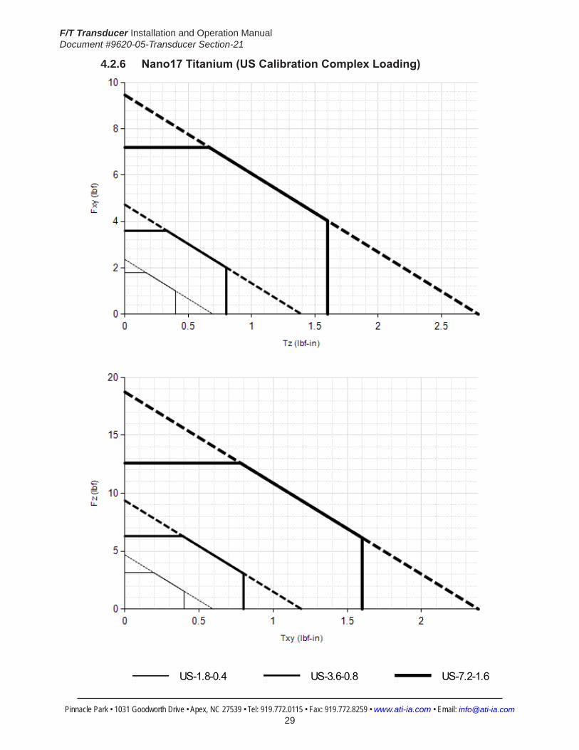
F/T Transducer Installation and Operation ManualDocument #9620-05-Transducer Section-21
Pinnacle Park • 1031 Goodworth Drive • Apex, NC 27539 • Tel: 919.772.0115 • Fax: 919.772.8259 • www.ati-ia.com • Email: [email protected] 29
4.2.6 Nano17Titanium(USCalibrationComplexLoading)
HelpNano17 Titanium
US-1.8-0.4 US-3.6-0.8 US-7.2-1.6
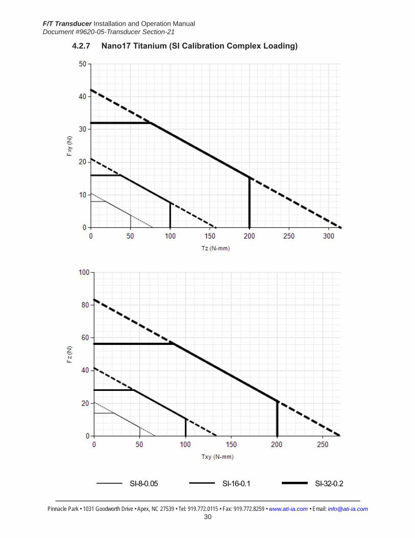
F/T Transducer Installation and Operation ManualDocument #9620-05-Transducer Section-21
Pinnacle Park • 1031 Goodworth Drive • Apex, NC 27539 • Tel: 919.772.0115 • Fax: 919.772.8259 • www.ati-ia.com • Email: [email protected] 30
4.2.7 Nano17Titanium(SICalibrationComplexLoading)
HelpNano17 Titanium
SI-8-0.05 SI-16-0.1 SI-32-0.2
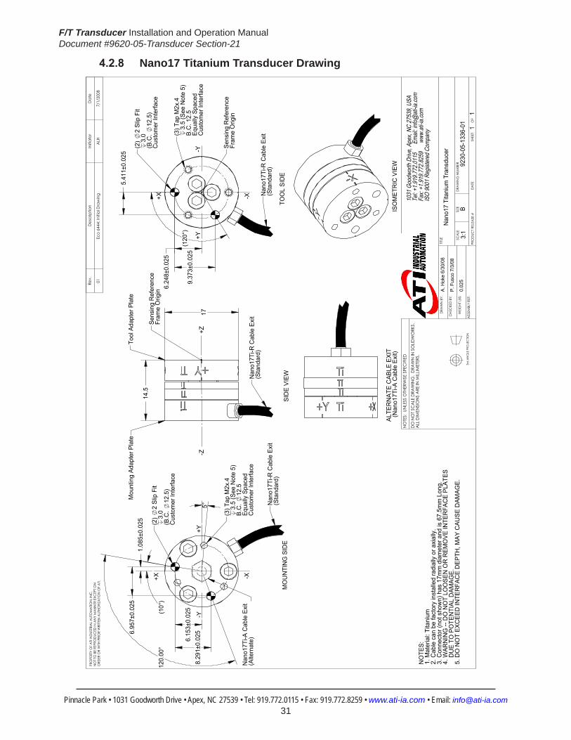
F/T Transducer Installation and Operation ManualDocument #9620-05-Transducer Section-21
Pinnacle Park • 1031 Goodworth Drive • Apex, NC 27539 • Tel: 919.772.0115 • Fax: 919.772.8259 • www.ati-ia.com • Email: [email protected] 31
4.2.8 Nano17 Titanium Transducer Drawing
5°
120.
00°
8.29
1±0.
025
6.15
3±0.
025(10°
)
6.95
7±0.
025
1.08
5±0.
025
(3) T
ap M
2x.4
3.5
(See
Not
e 5)
B.C
. 12
.5Eq
ually
Spa
ced
Cus
tom
er In
terfa
ce
(2)
2 Sl
ip F
it3.
0 (B
.C.
12.5
)C
usto
mer
Inte
rface
-X
-Y+Y
+X
Nan
o17T
i-R C
able
Exi
t(S
tand
ard)
MO
UN
TIN
G S
IDE
Nan
o17T
i-A C
able
Exi
t (A
ltern
ate)
17
14.5
Nan
o17T
i-R C
able
Exi
t (S
tand
ard)
-Z+Z
Tool
Ada
pter
Pla
te
Sens
ing
Ref
eren
ce
Fram
e O
rigin
SID
E VI
EW
Mou
ntin
g Ad
apte
r Pla
te
6.24
8±0.
025
(120
°)9.
373±
0.02
5
5.41
1±0.
025
Sens
ing
Ref
eren
ceFr
ame
Orig
in
(2)
2 Sl
ip F
it 3.
0(B
.C.
12.5
)C
usto
mer
Inte
rface
(3) T
ap M
2x.4
3.5
(See
Not
e 5)
B.C
. 12.
5Eq
ually
Spa
ced
Cus
tom
er In
terfa
ce+Y
-Y
-X+X Nan
o17T
i-R C
able
Exi
t(S
tand
ard)
TOO
L SI
DE
ISO
MET
RIC
VIE
WAL
TER
NAT
E C
ABLE
EXI
T (N
ano1
7Ti-A
Cab
le E
xit)
NO
TES:
1. M
ater
ial:
Tita
nium
2.
Cab
le c
an b
e fa
ctor
y in
stal
led
radi
ally
or a
xial
ly.
3. C
onne
ctor
(not
sho
wn)
has
17m
m d
iam
eter
and
is 6
7.5m
m L
ong.
4. W
ARN
ING
-- D
O N
OT
LOO
SEN
OR
REM
OVE
INTE
RFA
CE
PLAT
ES
DU
E TO
PO
TEN
TIAL
DAM
AGE.
5. D
O N
OT
EXC
EED
INTE
RFA
CE
DEP
TH, M
AY C
AUSE
DAM
AGE.
Rev.
Des
crip
tion
Initi
ator
Dat
e
01Ec
o 64
44: I
nitia
l Dra
win
g A
LH7/
1/20
08
1031
Goo
dwor
th Dr
ive, A
pex,
NC 27
539,
USA
Tel: +
1.919
.772.0
115
Em
ail: in
fo@ati
-ia.co
mFa
x: +1
.919.7
72.82
59
www
.ati-ia
.com
ISO
9001
Reg
ister
ed C
ompa
ny
NO
TES:
UN
LESS
OTH
ERW
ISE
SPEC
IFIED
DO
NO
T SC
ALE
DRA
WIN
G.
DRA
WN
IN S
OLID
WO
RKS.
ALL
DIM
ENSI
ON
S A
RE IN
MILL
IMET
ERS.
3rd
AN
GLE
PRO
JEC
TION
DRA
WN
BY:
CHE
CKE
D B
Y:
WEI
GHT
LBS
:
ASS
EMBL
Y RE
F:
A. H
oke
6/30
/08
P. F
usco
7/3
/08
TITLE SC
ALE
SIZE
DRA
WIN
G N
UMBE
R
PRO
DUC
T REL
EASE
#D
ATE
:SH
EET
O
F
PRO
PERT
Y O
F A
TI IN
DUS
TRIA
L A
UTO
MA
TION
, IN
C.
NO
T TO
BE
REPR
OD
UCED
IN A
NY
MA
NN
ER E
XCEP
T ON
ORD
ER O
R W
ITH P
RIO
R W
RITT
EN A
UTHO
RIZA
TION
OF
ATI.
Nan
o17
Tita
nium
Tra
nsdu
cer
9230
-05-
1336
-01
B3:
11
1
0.02
5

F/T Transducer Installation and Operation ManualDocument #9620-05-Transducer Section-21
Pinnacle Park • 1031 Goodworth Drive • Apex, NC 27539 • Tel: 919.772.0115 • Fax: 919.772.8259 • www.ati-ia.com • Email: [email protected] 32
4.3 Nano17Specifications(IncludesIP65/IP68Versions)4.3.1 Nano17 Physical Properties
Table 4.6—Nano17 Physical PropertiesSingle-Axis Overload (US)StandardUnits (SI)MetricUnitsFxy ±56 lbf ±250 NFz ±110 lbf ±480 NTxy ±14 inf-lb ±1.6 NmTz ±16 inf-lb ±1.8 NmStiffness(Calculated) X-axis&Y-axisforces(Kx,Ky) 4.7x10⁴ lb/in 8.2x10⁶ N/m Z-axisforce(Kz) 6.5x10⁴ lb/in 1.1x10⁷ N/m X-axis&Y-axistorque(Ktx,Kty) 2.1x10³ lbf-in/rad 2.4x10² Nm/rad Z-axistorque(Ktz) 3.4x10³ lbf-in/rad 3.8x10² Nm/rad Resonant Frequency Fx, Fy, Tz 7200 Hz 7200 HzFz, Tx, Ty 7200 Hz 7200 HzPhysicalSpecifications Weight1 0.02 lb 0.00907 kgDiameter1 0.669 in 17 mmHeight1 0.571 in 14.5 mmNote: 1.Specificationsincludestandardinterfaceplates.
4.3.2 Nano17IP65/IP68PhysicalPropertiesTable 4.7—Nano17IP65/IP68PhysicalProperties
Single-Axis Overload (US)StandardUnits (SI)MetricUnitsFxy ±56 lbf ±250 NFz ±110 lbf ±480 NTxy ±14 inf-lb ±1.6 NmTz ±16 inf-lb ±1.8 NmStiffness(Calculated) X-axis&Y-axisforces(Kx,Ky) 4.7x10⁴ lb/in 8.2x10⁶ N/m Z-axisforce(Kz) 6.5x10⁴ lb/in 1.1x10⁷ N/m X-axis&Y-axistorque(Ktx,Kty) 2.1x10³ lbf-in/rad 2.4x10² Nm/rad Z-axistorque(Ktz) 3.4x10³ lbf-in/rad 3.8x10² Nm/rad Resonant Frequency Fx, Fy, Tz 2200 Hz 2200 HzFz, Tx, Ty 2200 Hz 2200 HzPhysicalSpecifications Weight1 0.09 lb 0.0408 kgDiameter1 0.79 in 20.1 mmHeight1 0.873 in 22.2 mmNote: 1.Specificationsincludestandardinterfaceplates.
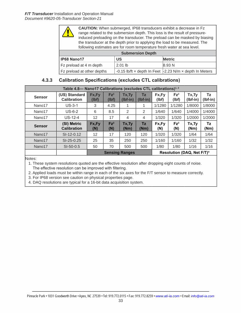
F/T Transducer Installation and Operation ManualDocument #9620-05-Transducer Section-21
Pinnacle Park • 1031 Goodworth Drive • Apex, NC 27539 • Tel: 919.772.0115 • Fax: 919.772.8259 • www.ati-ia.com • Email: [email protected] 33
CAUTION: When submerged, IP68 transducers exhibit a decrease in Fz range related to the submersion depth. This loss is the result of pressure-induced preloading on the transducer. The preload can be masked by biasing the transducer at the depth prior to applying the load to be measured. The following estimates are for room temperature fresh water at sea level.
Submersion DepthIP68Nano17 US MetricFz preload at 4 m depth 2.01 lb 8.93 NFz preload at other depths -0.15 lb/ft × depth In Feet -2.23 N/m × depth In Meters
4.3.3 CalibrationSpecifications(excludesCTLcalibrations)
Table4.8—Nano17Calibrations(excludesCTLcalibrations)1, 2
Sensor (US)Standard Calibration
Fx,Fy (lbf)
Fz3 (lbf)
Tx,Ty (lbf-in)
Tz (lbf-in)
Fx,Fy (lbf)
Fz3 (lbf)
Tx,Ty (lbf-in)
Tz (lbf-in)
Nano17 US-3-1 3 4.25 1 1 1/1280 1/1280 1/8000 1/8000Nano17 US-6-2 6 8.5 2 2 1/640 1/640 1/4000 1/4000Nano17 US-12-4 12 17 4 4 1/320 1/320 1/2000 1/2000
Sensor (SI)Metric Calibration
Fx,Fy (N)
Fz3 (N)
Tx,Ty (Nm)
Tz (Nm)
Fx,Fy (N)
Fz3 (N)
Tx,Ty (Nm)
Tz (Nm)
Nano17 SI-12-0.12 12 17 120 120 1/320 1/320 1/64 1/64Nano17 SI-25-0.25 25 35 250 250 1/160 1/160 1/32 1/32Nano17 SI-50-0.5 50 70 500 500 1/80 1/80 1/16 1/16
Sensing Ranges Resolution(DAQ,NetF/T)4
Notes: 1. These system resolutions quoted are the effective resolution after dropping eight counts of noise. Theeffectiveresolutioncanbeimprovedwithfiltering. 2. Applied loads must be within range in each of the six axes for the F/T sensor to measure correctly. 3. For IP68 version see caution on physical properties page. 4. DAQ resolutions are typical for a 16-bit data acquisition system.

F/T Transducer Installation and Operation ManualDocument #9620-05-Transducer Section-21
Pinnacle Park • 1031 Goodworth Drive • Apex, NC 27539 • Tel: 919.772.0115 • Fax: 919.772.8259 • www.ati-ia.com • Email: [email protected] 34
4.3.4 CTLCalibrationSpecificationsTable 4.9— Nano17 CTL Calibrations1, 2
Sensor (US)Standard Calibration
Fx,Fy (lbf)
Fz3 (lbf)
Tx,Ty (lbf-in)
Tz (lbf-in)
Fx,Fy (lbf)
Fz3 (lbf)
Tx,Ty (lbf-in)
Tz (lbf-in)
Nano17 US-3-1 3 4.25 1 1 1/640 1/640 1/4000 1/4000Nano17 US-6-2 6 8.5 2 2 1/320 1/320 1/2000 1/2000Nano17 US-12-4 12 17 4 4 1/160 1/160 1/1000 1/1000
Sensor (SI)Metric Calibration
Fx,Fy (N)
Fz3 (N)
Tx,Ty (Nm)
Tz (Nm)
Fx,Fy (N)
Fz3 (N)
Tx,Ty (Nm)
Tz (Nm)
Nano17 SI-12-0.12 12 17 120 120 1/160 1/160 1/32 1/32Nano17 SI-25-0.25 25 35 250 250 1/80 1/80 1/16 1/16Nano17 SI-50-0.5 50 70 500 500 1/40 1/40 1/8 1/8
Sensing Ranges Resolution(Controller)Notes: 1. CTL resolutions are typical. System resolutions quoted are the effective resolution after dropping eight countsofnoise.Theeffectiveresolutioncanbeimprovedwithfiltering. 2. Applied loads must be within range in each of the six axes for the F/T sensor to measure correctly. 3. For IP68 version see caution on physical properties page.
4.3.5 Analog OutputTable 4.10— Nano17 Analog Output
Sensor (US)Standard Calibration
Fx,Fy (lbf)
Fz2 (lbf)
Tx,Ty,Tz (lbf-in)
Fx,Fy (lbf/V)
Fz2 (lbf/V)
Tx,Ty,Tz (lbf-in/V)
Nano17 US-3-1 ±3 ±4.25 ±1 0.3 0.425 0.1Nano17 US-6-2 ±6 ±8.5 ±2 0.6 0.85 0.2Nano17 US-12-4 ±12 ±17 ±4 1.2 1.7 0.4
Sensor (SI)Metric Calibration
Fx,Fy (N)
Fz2 (N)
Tx,Ty,Tz (Nmm)
Fx,Fy (N/V)
Fz2 (N/V)
Tx,Ty,Tz (Nm/V)
Nano17 SI-12-0.12 ±12 ±17 ±120 1.2 1.7 12Nano17 SI-25-0.25 ±25 ±35 ±250 2.5 3.5 25Nano17 SI-50-0.5 ±50 ±70 ±500 5 7 50
Analog Output Range Analog±10VSensitivity1
Notes: 1. ±5V Sensitivity values are double the listed ±10V Sensitivity values. 2. For IP68 version see caution on physical properties page.
4.3.6 CountsValueTable 4.11—CountsValue
Sensor Calibration Fx,Fy,Fz (/lbf)
Tx,Ty,Tz (/lbf-in)
Fx,Fy,Fz (/N)
Tx,Ty,Tz (/Nmm)
Nano17 US-3–1/SI-12–0.25 5120 32000 1280 256Nano17 US-6–2/SI-25–0.25 2560 16000 640 128Nano17 US-12–4/SI-50–0.5 1280 8000 320 64Nano17 Tool Transform Factor 0.0016 in/lbf 0.05 mm/N
CountsValue–Standard(US) CountsValue–Metric(SI)
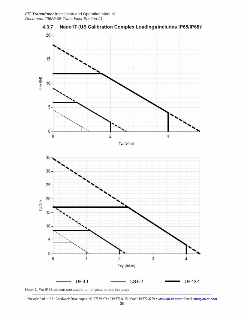
F/T Transducer Installation and Operation ManualDocument #9620-05-Transducer Section-21
Pinnacle Park • 1031 Goodworth Drive • Apex, NC 27539 • Tel: 919.772.0115 • Fax: 919.772.8259 • www.ati-ia.com • Email: [email protected] 35
4.3.7 Nano17(USCalibrationComplexLoading)(IncludesIP65/IP68)1
HelpNano17
US-3-1 US-6-2 US-12-4
Note: 1. For IP68 version see caution on physical properties page.

F/T Transducer Installation and Operation ManualDocument #9620-05-Transducer Section-21
Pinnacle Park • 1031 Goodworth Drive • Apex, NC 27539 • Tel: 919.772.0115 • Fax: 919.772.8259 • www.ati-ia.com • Email: [email protected] 36
4.3.8 Nano17(SICalibrationComplexLoading)(IncludesIP65/IP68)1
HelpNano17
SI-12-0.12 SI-25-0.25 SI-50-0.5
Note: 1. For IP68 version see caution on physical properties page.

F/T Transducer Installation and Operation ManualDocument #9620-05-Transducer Section-21
Pinnacle Park • 1031 Goodworth Drive • Apex, NC 27539 • Tel: 919.772.0115 • Fax: 919.772.8259 • www.ati-ia.com • Email: [email protected] 37
4.3.9 Nano17-E Transducer Drawing
1.08
5±0.
025
48°
5.3
6.95
7±0.
025
6.15
3±0.
025
8.29
1±0.
025
15.5
(B.C
.12
.5)
(2)
2.0
Sl
ip F
it 3
.0
17.6
5°
(3) M
2-.4
03.
5Eq
ually
Spa
ced
B.C
. 1
2.5
Cus
tom
er In
terfa
ce(S
ee N
ote
5)
MO
UN
TIN
G S
IDE
-X+X
+Y-Y
14.5
17-Z
Mou
ntin
gAd
apte
r
Tool
Ada
pter
Sens
ing
Ref
eren
ceFr
ame
Orig
in 6.24
8±0.
025
9.37
3±0.
025
5.41
1±0.
025
(2)
2.06
02.
035.0
Slip
Fit
3.0
(B.C
.12
.5)
SID
E VI
EW
+Z
Sens
ing
Ref
eren
ceFr
ame
Orig
in-X+X
+Y-Y
(3) M
2-.4
03.
5Eq
ually
Spa
ced
B.C
. 12
.5C
usto
mer
Inte
rface
(See
Not
e 5)
TOO
L SI
DE
ISO
MET
RIC
VIE
W
Not
es:
1. T
ool a
nd m
ount
ing
adap
ter m
ade
of a
lum
inum
.2.
Too
l and
mou
ntin
g ad
apte
r hav
e M
2 ta
pped
hol
es a
nd
2.0
mm
dow
el p
in h
oles
for c
usto
mer
inte
rface
.3.
Con
nect
or (n
ot s
how
n) h
as a
17m
m d
iam
eter
and
is
67.
5mm
long
.4.
WA
RN
ING
--DO
NO
T LO
OSE
N O
R R
EMO
VE IN
TER
FAC
E
PLA
TES
DU
E TO
PO
TEN
TIA
L D
AM
AG
E.5.
DO
NO
T EX
CEE
D IN
TER
FAC
E D
EPTH
--MA
Y C
AU
SE D
AM
AG
E
Rev.
Des
crip
tion
Initi
ator
Dat
e
01In
itial
Dra
win
gPP
F3/
8/20
07
02Up
date
d di
men
sions
from
stra
in re
lief t
o ce
nter
of p
art
PPF
5/27
/200
8
1031
Goo
dwor
th Dr
ive, A
pex,
NC 27
539,
USA
Tel: +
1.919
.772.0
115
Em
ail: in
fo@ati
-ia.co
mFa
x: +1
.919.7
72.82
59
www
.ati-ia
.com
ISO
9001
Reg
ister
ed C
ompa
ny
NO
TES:
UN
LESS
OTH
ERW
ISE
SPEC
IFIED
DO
NO
T SC
ALE
DRA
WIN
G.
DRA
WN
IN S
OLID
WO
RKS.
ALL
DIM
ENSI
ON
S A
RE IN
MILL
IMET
ERS.
3rd
AN
GLE
PRO
JEC
TION
DRA
WN
BY:
CHE
CKE
D B
Y:
WEI
GHT
LBS
:
ASS
EMBL
Y RE
F:
P. F
usco
3/8
/07
D. S
wan
son
3/9/
07
TITLE SC
ALE
SIZE
DRA
WIN
G N
UMBE
R
PRO
DUC
T REL
EASE
#D
ATE
:SH
EET
O
F
PRO
PERT
Y O
F A
TI IN
DUS
TRIA
L A
UTO
MA
TION
, IN
C.
NO
T TO
BE
REPR
OD
UCED
IN A
NY
MA
NN
ER E
XCEP
T ON
ORD
ER O
R W
ITH P
RIO
R W
RITT
EN A
UTHO
RIZA
TION
OF
ATI.
NAN
O17
-E T
RAN
SDU
CER
9230
-05-
1311
-02
B3:
11
1
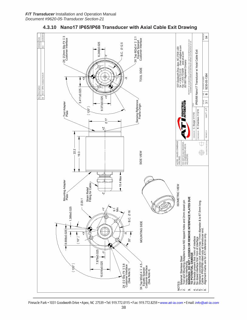
F/T Transducer Installation and Operation ManualDocument #9620-05-Transducer Section-21
Pinnacle Park • 1031 Goodworth Drive • Apex, NC 27539 • Tel: 919.772.0115 • Fax: 919.772.8259 • www.ati-ia.com • Email: [email protected] 38
4.3.10 Nano17IP65/IP68TransducerwithAxialCableExitDrawing
3rd
AN
GLE
PRO
JEC
TION
20.1
8.90
8 ±0.
025
120°
10.6
16±0
.0257.
879±
0.02
5
10°
1.38
9±0.
025
B.C
. 16
35°
9.1
Min
-Y
+X
3X T
ap M
2x0.
4 4
.5Eq
ually
Spa
ced
Cus
tom
er In
terfa
ce(S
ee N
ote
4)
2X
2 Sl
ip F
it 3.
8C
usto
mer
Inte
rface
(See
Not
e 5)
MO
UN
TIN
G S
IDE
22.2
19.3
10.4
Max
17
Stra
in R
elie
f Fi
tting
for C
able
Mou
ntin
g Ad
apte
r P
late
Tool
Ada
pter
Plat
e
SID
E VI
EW
9.37
3±0.
025
6.24
8±0.
025
5.41
1±0.
025
B.C
. 12
.5
120°
TOO
L SI
DE
3X T
ap M
2x0.
4 2
.1Eq
ually
Spa
ced
Cus
tom
er In
terfa
ce
2X
2mm
Slip
Fit
3C
usto
mer
Inte
rface
ISO
MET
RIC
VIE
W
+Y
-X
+X
+Y
-X
-Y-Z
+Z
Sens
ing
Ref
eren
ceFr
ame
Orig
in
NO
TES: Mat
eria
l: St
ainl
ess
Stee
l1.
Tool
and
Mou
ntin
g Ad
apte
rs h
ave
M2
tapp
ed h
oles
and
2m
m d
owel
pin
2.
hole
s fo
r int
erfa
cing
WA
RN
ING
: DO
NO
T LO
OSE
N O
R R
EMO
VE IN
TER
FAC
E PL
ATE
S D
UE
3.TO
PO
TEN
TIA
L D
AM
AG
EN
o th
read
s pr
esen
t firs
t 1m
m o
f int
erfa
ce4.
No
dow
el in
terfa
ce fi
rst 1
mm
of i
nter
face
5.St
anda
rd c
onne
ctor
(not
sho
wn)
has
17m
m d
iam
eter
& is
67.
5mm
long
.6.
Cab
le is
IP65
/IP68
rate
d on
ly a
t tra
nsdu
cer e
nd.
7.Al
ignm
ent m
arks
are
for A
TI re
fere
nce
only
.8.
Rev.
Des
crip
tion
Initi
ator
Dat
e
04EC
O 1
3994
; Add
ed N
ote
8SZ
J5/
23/2
016
B3:
11
1RE
VISIO
N
NO
TES:
UN
LESS
OTH
ERW
ISE
SPEC
IFIED
.
DO
NO
T SC
ALE
DRA
WIN
G.
ALL
DIM
ENSI
ON
S A
RE IN
M
ILLIM
ETER
S.
DRA
WN
BY:
CHE
CKE
D B
Y:
C. S
turg
is 1
/11/
10
R. C
ham
bers
1/1
2/10
TITLE SC
ALE
SIZE
DRA
WIN
G N
UMBE
R
PRO
JEC
T #SH
EET
O
F 92
30-0
5-13
6404
PRO
PERT
Y O
F A
TI IN
DUS
TRIA
L A
UTO
MA
TION
, IN
C. N
OT T
O B
E RE
PRO
DUC
ED IN
AN
Y M
AN
NER
EXC
EPT O
N O
RDER
OR
WITH
PRI
OR
WRI
TTEN
AUT
HORI
ZATIO
N O
F A
TI.
1031
Goo
dwor
th Dr
ive, A
pex,
NC 27
539,
USA
Tel: +
1.919
.772.0
115
Em
ail: in
fo@ati
-ia.co
mFa
x: +1
.919.7
72.82
59
www
.ati-ia
.com
ISO
9001
Reg
ister
ed C
ompa
ny
IP65
/68
Nan
o17
Tran
sduc
er w
/ Axi
al C
able
Exi
t

F/T Transducer Installation and Operation ManualDocument #9620-05-Transducer Section-21
Pinnacle Park • 1031 Goodworth Drive • Apex, NC 27539 • Tel: 919.772.0115 • Fax: 919.772.8259 • www.ati-ia.com • Email: [email protected] 39
4.3.11 Legacy Nano17 Transducer Drawing
Cus
tom
er In
terfa
ce
(2)
2 Sli
p Fit
3.
0(B
.C.
12.5
)
6.24
8±0.
025
120°
9.37
3±0.
025
5.41
1±0.
025
(3)T
ap M
2x.4
0 3.
5B.
C.
12.5
Equa
lly S
pace
dC
usto
mer
Inte
rface
(See
Not
e 3)
-X
-Y
+X
+Y
Nan
o17-
R C
able
Exit
(Sta
ndar
d)
Sens
ing
Refe
renc
eFr
ame
Orig
in
14.5
0
17+Z
-Z
Mou
ntin
g A
dapt
erPl
ate
Tool
Ada
pter
Pla
te
Nan
o17-
R C
able
Exit
(Sta
ndar
d)
SID
E VI
EWTO
OL
SID
E
Sens
ing
Refe
renc
e Fr
ame
Orig
in
(See
Not
e 3)
(2)
2 Sli
p Fit
3
.0(B
.C.
12.5
)C
usto
mer
Inte
rface
8.29
1±0.
025
6.95
7±0.
025
6.15
3±0.
025
1.08
5±0.
025
3.8
5°
30°
120°
10°
Nan
o17-
A C
able
Exit
(Alte
rnat
e)
+Y
(3)T
ap M
2x.4
0 3.
5B.
C.
12.5
Equa
lly S
pace
dC
usto
mer
Inte
rface
(See
Not
e 3)
MO
UNTIN
G S
IDE
+X
-Y
-X
Nan
o17-
R C
able
Exit
(Sta
ndar
d)
NA
NO
17-R
ISO
MET
RIC
VIE
WA
LTER
NA
TE C
ABL
E EX
ITN
AN
O17
-AA
LTER
NA
TE C
ABL
E EX
ITN
AN
O17
-E
Not
es:
1. M
ount
ing
and
Tool
Ada
pter
mad
e of
Alu
min
um.
Tr
ansd
ucer
mad
e of
har
dene
d St
ainl
ess S
teel
.2.
WAR
NING
: DO
NO
T LO
OSE
N O
R RE
MO
VE IN
TERF
ACE
PLAT
ES
OR
CAB
LE F
ITTIN
G D
UE TO
PO
TENT
IAL D
AMAG
E.3.
DO
NO
T EXC
EED
INTE
RFAC
E DE
PTH,
MAY
CAU
SE D
AMAG
E.4.
Con
nect
or (n
ot sh
own)
has
17m
m d
iam
eter
and
is 6
7.5m
m lo
ng.
Rev.
Des
crip
tion
Initi
ator
Dat
e
13Ec
o 76
35; A
dd -E
cab
le e
xitC
CS
3/15
/201
0
B3:
11
1
REVI
SION
NO
TES:
UN
LESS
OTH
ERW
ISE
SPEC
IFIED
DO
NO
T SC
ALE
DRA
WIN
G.
DRA
WN
IN S
OLID
WO
RKS.
ALL
DIM
ENSI
ON
S A
RE IN
MILL
IMET
ERS.
3rd
AN
GLE
PRO
JEC
TION
DRA
WN
BY:
CHE
CKE
D B
Y:
WEI
GHT
LBS
:
ASS
EMBL
Y RE
F:
B. D
iges
o
D. P
erry
TITLE SC
ALE
SIZE
DRA
WIN
G N
UMBE
R
PRO
DUC
T REL
EASE
#SH
EET
O
F
9230
-05-
1073
B3:
11
1-
REVI
SION
13
PRO
PERT
Y O
F A
TI IN
DUS
TRIA
L A
UTO
MA
TION
, IN
C. N
OT T
O B
E RE
PRO
DUC
ED IN
AN
Y M
AN
NER
EXC
EPT O
N O
RDER
OR
WITH
PRI
OR
WRI
TTEN
AUT
HORI
ZATIO
N O
F A
TI.
1031
Goo
dwor
th Dr
ive, A
pex,
NC 27
539,
USA
Tel: +
1.919
.772.0
115
Em
ail: in
fo@ati
-ia.co
mFa
x: +1
.919.7
72.82
59
www
.ati-ia
.com
ISO
9001
Reg
ister
ed C
ompa
ny
Nan
o17
Tran
sduc
er DA
TE:
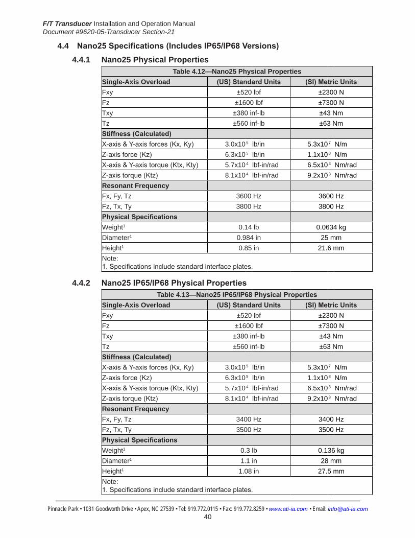
F/T Transducer Installation and Operation ManualDocument #9620-05-Transducer Section-21
Pinnacle Park • 1031 Goodworth Drive • Apex, NC 27539 • Tel: 919.772.0115 • Fax: 919.772.8259 • www.ati-ia.com • Email: [email protected] 40
4.4 Nano25Specifications(IncludesIP65/IP68Versions)4.4.1 Nano25 Physical Properties
Table 4.12—Nano25 Physical PropertiesSingle-Axis Overload (US)StandardUnits (SI)MetricUnitsFxy ±520 lbf ±2300 NFz ±1600 lbf ±7300 NTxy ±380 inf-lb ±43 NmTz ±560 inf-lb ±63 NmStiffness(Calculated) X-axis&Y-axisforces(Kx,Ky) 3.0x10⁵ lb/in 5.3x10⁷ N/m Z-axisforce(Kz) 6.3x10⁵ lb/in 1.1x10⁸ N/m X-axis&Y-axistorque(Ktx,Kty) 5.7x10⁴ lbf-in/rad 6.5x10³ Nm/rad Z-axistorque(Ktz) 8.1x10⁴ lbf-in/rad 9.2x10³ Nm/rad Resonant Frequency Fx, Fy, Tz 3600 Hz 3600 HzFz, Tx, Ty 3800 Hz 3800 HzPhysicalSpecifications Weight1 0.14 lb 0.0634 kgDiameter1 0.984 in 25 mmHeight1 0.85 in 21.6 mmNote: 1.Specificationsincludestandardinterfaceplates.
4.4.2 Nano25IP65/IP68PhysicalPropertiesTable 4.13—Nano25IP65/IP68PhysicalProperties
Single-Axis Overload (US)StandardUnits (SI)MetricUnitsFxy ±520 lbf ±2300 NFz ±1600 lbf ±7300 NTxy ±380 inf-lb ±43 NmTz ±560 inf-lb ±63 NmStiffness(Calculated) X-axis&Y-axisforces(Kx,Ky) 3.0x10⁵ lb/in 5.3x10⁷ N/m Z-axisforce(Kz) 6.3x10⁵ lb/in 1.1x10⁸ N/m X-axis&Y-axistorque(Ktx,Kty) 5.7x10⁴ lbf-in/rad 6.5x10³ Nm/rad Z-axistorque(Ktz) 8.1x10⁴ lbf-in/rad 9.2x10³ Nm/rad Resonant Frequency Fx, Fy, Tz 3400 Hz 3400 HzFz, Tx, Ty 3500 Hz 3500 HzPhysicalSpecifications Weight1 0.3 lb 0.136 kgDiameter1 1.1 in 28 mmHeight1 1.08 in 27.5 mmNote: 1.Specificationsincludestandardinterfaceplates.

F/T Transducer Installation and Operation ManualDocument #9620-05-Transducer Section-21
Pinnacle Park • 1031 Goodworth Drive • Apex, NC 27539 • Tel: 919.772.0115 • Fax: 919.772.8259 • www.ati-ia.com • Email: [email protected] 41
CAUTION: When submerged, IP68 transducers exhibit a decrease in Fz range related to the submersion depth. This loss is the result of pressure-induced preloading on the transducer. The preload can be masked by biasing the transducer at the depth prior to applying the load to be measured. The following estimates are for room temperature fresh water at sea level.
Submersion DepthIP68Nano17 US MetricFz preload at 4 m depth 4.33 lb 19.3 NFz preload at other depths -0.33 lb/ft × depthInFeet -4.81 N/m × depthInMeters
NOTICE: The outer body of the IP65 and the IP68 versions of the Nano25 are electricallyfloatingfromtherestofthesystem.Ifthetransducersignalhasadditionalnoise, it may be necessary to electrically connect the transducer body to the case of the F/T system.
4.4.3 CalibrationSpecifications(excludesCTLcalibrations)
Table 4.14—Nano25Calibrations(excludesCTLcalibrations)1, 2, 4
Sensor (US)Standard Calibration
Fx,Fy (lbf)
Fz3 (lbf)
Tx,Ty (lbf-in)
Tz (lbf-in)
Fx,Fy (lbf)
Fz3 (lbf)
Tx,Ty (lbf-in)
Tz (lbf-in)
Nano25 US-25-25 25 100 25 25 1/224 3/224 1/160 1/320Nano25 US-50-50 50 200 50 30 1/112 3/112 1/80 1/160
Sensor (SI)Metric Calibration
Fx,Fy (N)
Fz3 (N)
Tx,Ty (Nm)
Tz (Nm)
Fx,Fy (N)
Fz3 (N)
Tx,Ty (Nm)
Tz (Nm)
Nano25 SI-125-3 125 500 3 3 1/48 1/16 1/1320 1/2640Nano25 SI-250-6 250 1000 6 3.4 1/24 1/8 1/660 1/1320
Sensing Ranges Resolution(DAQ,NetF/T)5
Notes: 1. These system resolutions quoted are the effective resolution after dropping four counts of noise. Theeffectiveresolutioncanbeimprovedwithfiltering. 2. Applied loads must be within range in each of the six axes for the F/T sensor to measure correctly. 3. For IP68 version see caution on physical properties page. 4.Applyingmomentsbeyond±30lbf-in(±3.4Nm)inTzcancausehysteresisandpermanentzero-point changeintheNano25(appliestoallversionsoftheNano25). 5. DAQ resolutions are typical for a 16-bit data acquisition system.

F/T Transducer Installation and Operation ManualDocument #9620-05-Transducer Section-21
Pinnacle Park • 1031 Goodworth Drive • Apex, NC 27539 • Tel: 919.772.0115 • Fax: 919.772.8259 • www.ati-ia.com • Email: [email protected] 42
4.4.4 CTLCalibrationSpecificationsTable 4.15— Nano25 CTL Calibrations1, 2, 4
Sensor (US)Standard Calibration
Fx,Fy (lbf)
Fz3 (lbf)
Tx,Ty (lbf-in)
Tz (lbf-in)
Fx,Fy (lbf)
Fz3 (lbf)
Tx,Ty (lbf-in)
Tz (lbf-in)
Nano25 US-25-25 25 100 25 25 1/112 3/112 1/80 1/160Nano25 US-50-50 50 200 50 30 1/56 3/56 1/40 1/80
Sensor (SI)Metric Calibration
Fx,Fy (N)
Fz3 (N)
Tx,Ty (Nm)
Tz (Nm)
Fx,Fy (N)
Fz3 (N)
Tx,Ty (Nm)
Tz (Nm)
Nano25 SI-125-3 125 500 3 3 1/24 1/8 1/660 1/1320Nano25 SI-250-6 250 1000 6 3.4 1/12 1/4 1/330 1/660
Sensing Ranges Resolution(Controller)Notes: 1. CTL resolutions are typical. System resolutions quoted are the effective resolution after dropping eight countsofnoise.Theeffectiveresolutioncanbeimprovedwithfiltering. 2. Applied loads must be within range in each of the six axes for the F/T sensor to measure correctly. 3. For IP68 version see caution on physical properties page. 4.Applyingmomentsbeyond±30lbf-in(±3.4Nm)inTzcancausehysteresisandpermanentzero-point changeintheNano25(appliestoallversionsoftheNano25).
4.4.5 Analog Output
Table 4.16— Nano25 Analog Output
Sensor (US)Standard Calibration
Fx,Fy (lbf)
Fz2 (lbf)
Tx,Ty,Tz (lbf-in)
Fx,Fy (lbf/V)
Fz2 (lbf/V)
Tx,Ty,Tz (lbf-in/V)
Nano25 US-25-25 ±25 ±100 ±25 2.5 10 2.5Nano25 US-50-50 ±50 ±200 ±50 5 20 5
Sensor (SI)Metric Calibration
Fx,Fy (N)
Fz2 (N)
Tx,Ty,Tz (Nmm)
Fx,Fy (N/V)
Fz2 (N/V)
Tx,Ty,Tz (Nm/V)
Nano25 SI-125-3 ±125 ±500 ±3 12.5 50 0.3Nano25 SI-250-6 ±250 ±1000 ±6 25 100 0.6
Analog Output Range Analog±10VSensitivity1
Notes: 1. ±5V Sensitivity values are double the listed ±10V Sensitivity values. 2. For IP68 version see caution on physical properties page.
4.4.6 CountsValue
Table 4.17—CountsValue
Sensor Calibration Fx,Fy,Fz (/lbf)
Tx,Ty,Tz (/lbf-in) Fx,Fy,Fz Tx,Ty,Tz
Nano25 US-25–25/SI-125–3 896 1280 192 / N 10560 / NNano25 US-50–50/SI-250–6 448 640 96 / Nm 5280 / NmNano25 Tool Transform Factor 0.007 in/lbf 0.18182 mm/N
CountsValue–Standard(US) CountsValue–Metric(SI)
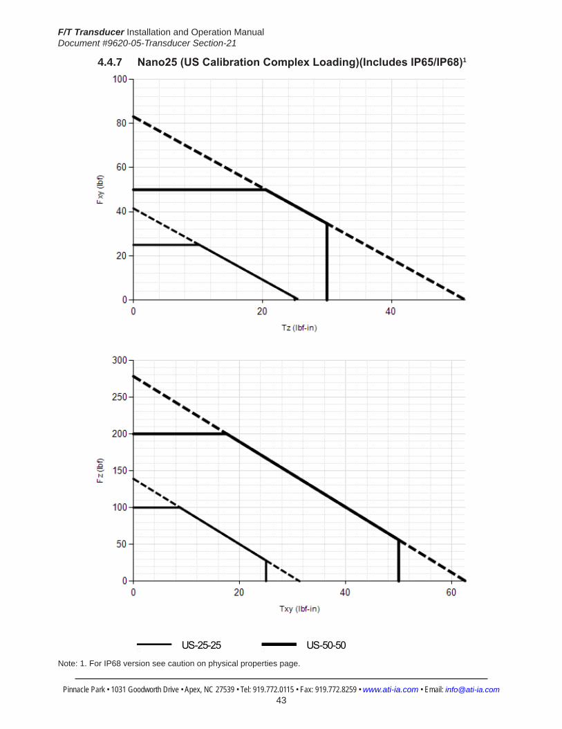
F/T Transducer Installation and Operation ManualDocument #9620-05-Transducer Section-21
Pinnacle Park • 1031 Goodworth Drive • Apex, NC 27539 • Tel: 919.772.0115 • Fax: 919.772.8259 • www.ati-ia.com • Email: [email protected] 43
4.4.7 Nano25(USCalibrationComplexLoading)(IncludesIP65/IP68)1
HelpNano25
US-25-25 US-50-50
Note: 1. For IP68 version see caution on physical properties page.

F/T Transducer Installation and Operation ManualDocument #9620-05-Transducer Section-21
Pinnacle Park • 1031 Goodworth Drive • Apex, NC 27539 • Tel: 919.772.0115 • Fax: 919.772.8259 • www.ati-ia.com • Email: [email protected] 44
4.4.8 Nano25(SICalibrationComplexLoading)(IncludesIP65/IP68)1
HelpNano25
SI-125-3 SI-250-6
Note: 1. For IP68 version see caution on physical properties page.

F/T Transducer Installation and Operation ManualDocument #9620-05-Transducer Section-21
Pinnacle Park • 1031 Goodworth Drive • Apex, NC 27539 • Tel: 919.772.0115 • Fax: 919.772.8259 • www.ati-ia.com • Email: [email protected] 45
4.4.9 Nano25-E Transducer Drawing
3rd
AN
GLE
PRO
JEC
TION
29.6
5.3
6.06
06.
035
2.1
Cus
tom
er In
terfa
ce
4.29
4±0.
025
9.20
8±0.
025
B.C
. 20
.32
3X M
3-0.
5 7.
0Eq
ually
Spa
ced
Cus
tom
er In
terfa
ce(S
ee N
ote
3)
-Y
-X+X
3 S
lip F
it 7
.0C
usto
mer
Inte
rface
25
21.6
4.8
Sens
ing
Ref
eren
ceFr
ame
Orig
in
Tool
Ada
pter
Mou
ntin
g Ad
apte
r
-Z+Z
10.1
60±0
.025
15.2
40±0
.025
8.79
9±0.
025
B.C
. 20
.32
2X
3 Sl
ip F
it 3.
3C
usto
mer
Inte
rface
3X M
3-0.
5 3.
5Eq
ually
Spa
ced
Cus
tom
er In
terfa
ce(S
ee N
ote
5)
Sens
ing
Ref
eren
ceFr
ame
Orig
in
-X
-Y+Y
+X
ISO
MET
RIC
VIE
W
MO
UN
TIN
G S
IDE
SID
E VI
EWTO
OL
SID
E
Not
es: Mou
ntin
g an
d To
ol A
dapt
er m
ade
of S
tain
less
Ste
el.
Tran
sduc
er
1.m
ade
of h
arde
ned
Stai
nles
s St
eel.
WA
RN
ING
: DO
NO
T LO
OSE
N O
R R
EMO
VE IN
TER
FAC
E PL
ATE
S O
R C
AB
LE2.
DU
E TO
PO
TEN
TIA
L D
AM
AG
E.D
O N
OT
EXC
EED
INTE
RFA
CE
DEP
TH. M
AY
CA
USE
DA
MA
GE.
3.St
anda
rd c
onne
ctor
(not
sho
wn)
has
a 1
7mm
dia
met
er a
nd is
67.
5mm
long
.4.
+Y
Rev.
Des
crip
tion
Initi
ator
Dat
e
02Ec
o 10
898;
cor
rect
TAP
dow
el to
3, u
pdat
e no
tes
LJH
4/11
/201
3
B2:
11
1RE
VISIO
N
NO
TES:
UN
LESS
OTH
ERW
ISE
SPEC
IFIED
.
DO
NO
T SC
ALE
DRA
WIN
G.
ALL
DIM
ENSI
ON
S A
RE IN
M
ILLIM
ETER
S.
DRA
WN
BY:
CHE
CKE
D B
Y:
R. C
ham
bers
, 8/2
9/07
P. F
usco
, 2/2
2/08
TITLE SC
ALE
SIZE
DRA
WIN
G N
UMBE
R
PRO
JEC
T #SH
EET
O
F 92
30-0
5-13
12-
02
PRO
PERT
Y O
F A
TI IN
DUS
TRIA
L A
UTO
MA
TION
, IN
C. N
OT T
O B
E RE
PRO
DUC
ED IN
AN
Y M
AN
NER
EXC
EPT O
N O
RDER
OR
WITH
PRI
OR
WRI
TTEN
AUT
HORI
ZATIO
N O
F A
TI.
1031
Goo
dwor
th Dr
ive, A
pex,
NC 27
539,
USA
Tel: +
1.919
.772.0
115
Em
ail: in
fo@ati
-ia.co
mFa
x: +1
.919.7
72.82
59
www
.ati-ia
.com
ISO
9001
Reg
ister
ed C
ompa
ny
Nan
o25-
E Tr
ansd
ucer
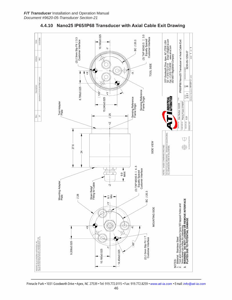
F/T Transducer Installation and Operation ManualDocument #9620-05-Transducer Section-21
Pinnacle Park • 1031 Goodworth Drive • Apex, NC 27539 • Tel: 919.772.0115 • Fax: 919.772.8259 • www.ati-ia.com • Email: [email protected] 46
4.4.10 Nano25IP65/IP68TransducerwithAxialCableExitDrawing
BC
20.3
(2)
3mm
Slip
Fit
3.3
Cus
tom
er In
terfa
ce
120°
8.79
9±0.
025
15.2
40±0
.025
10.1
60±0
.025
Cus
tom
er In
terfa
ceEq
ually
Spa
ced
(3) T
AP M
3X0.
5
3.0
Sens
ing
Ref
eren
ceFr
ame
Orig
in
+X -X
+Y-Y
27.6
25
24
9.9
MAX
Stra
in R
elie
fFi
tting
for C
able
Mou
ntin
g Ad
apte
rPl
ate
Tool
Ada
pter
Plat
e
Sens
ing
Ref
eren
ceFr
ame
Orig
in
+Z-Z
28
BC
20.3
65°
(2)
3mm
Slip
Fit
7C
usto
mer
Inte
rface
10.1
60±0
.025
9.20
8±0.
025
14.4
54±0
.025
Cus
tom
er In
terfa
ceEq
ually
Spa
ced
(3) T
AP M
3X0.
5 4
..5
9.1
Min
+X -X
+Y-Y
NO
TES:
1.
Mat
eria
l: S
tain
less
Ste
el2.
To
ol a
nd m
ount
ing
adap
ters
hav
e M
3 ta
pped
hol
es a
nd
3mm
dow
el p
in h
oles
for i
nter
faci
ng3.
W
AR
NIN
G:
DO
NO
T LO
OSE
N O
R R
EMO
VE IN
TER
FAC
E
PL
ATE
S D
UE
TO P
OTE
NTI
AL
DA
MA
GE
MO
UN
TIN
G S
IDE
SID
E VI
EWTO
OL
SID
E
Rev.
Des
crip
tion
Initi
ator
Dat
e
07Up
date
d to
incl
ude
IP68
ver
sion
RKC
12/3
/200
8
1031
Goo
dwor
th Dr
ive, A
pex,
NC 27
539,
USA
Tel: +
1.919
.772.0
115
Em
ail: in
fo@ati
-ia.co
mFa
x: +1
.919.7
72.82
59
www
.ati-ia
.com
ISO
9001
Reg
ister
ed C
ompa
ny
NO
TES:
UN
LESS
OTH
ERW
ISE
SPEC
IFIED
DO
NO
T SC
ALE
DRA
WIN
G.
DRA
WN
IN S
OLID
WO
RKS.
ALL
DIM
ENSI
ON
S A
RE IN
MILL
IMET
ERS.
3rd
AN
GLE
PRO
JEC
TION
DRA
WN
BY:
CHE
CKE
D B
Y:
WEI
GHT
LBS
:
ASS
EMBL
Y RE
F:
Dan
Nor
ton
12/2
/05
Penn
y Fu
sco
3/16
/07
TITLE SC
ALE
SIZE
DRA
WIN
G N
UMBE
R
PRO
DUC
T REL
EASE
#D
ATE
:SH
EET
O
F
PRO
PERT
Y O
F A
TI IN
DUS
TRIA
L A
UTO
MA
TION
, IN
C.
NO
T TO
BE
REPR
OD
UCED
IN A
NY
MA
NN
ER E
XCEP
T ON
ORD
ER O
R W
ITH P
RIO
R W
RITT
EN A
UTHO
RIZA
TION
OF
ATI.
IP65
/IP68
Nan
o25
Tran
sduc
er w
/ Axi
al C
able
Exi
t
9230
-05-
1259
-07
B2.
5:1
11
0.21
0512
01-2

F/T Transducer Installation and Operation ManualDocument #9620-05-Transducer Section-21
Pinnacle Park • 1031 Goodworth Drive • Apex, NC 27539 • Tel: 919.772.0115 • Fax: 919.772.8259 • www.ati-ia.com • Email: [email protected] 47
4.4.11 Nano25IP65/IP68TransducerwithRadialCableExitDrawing
28
10.1
60±0
.025
14.4
54±0
.025
9.20
8±0.
025
(2)
3 Sl
ip F
it7
Cus
tom
er In
terfa
ce
Cus
tom
er In
terfa
ceEq
ually
Spa
ced
(3) T
ap M
3X0.
5 4
.5
B.C
. 20
.3
23.9
MAX
30°
7.4
14
30°
Rad
ial C
able
Exi
t
+X -X
-Y+Y
29.9
26.3
25Sens
ing
Ref
eren
ceFr
ame
Orig
in
Mou
ntin
g Ad
apte
rPl
ate
Tool
Ada
pter
Plat
e
+Z-Z
10.1
60±0
.025
15.2
40±0
.025
8.79
9±0.
025
B.C
. 20
.3
Cus
tom
er In
terfa
ceEq
ually
Spa
ced
(3) T
ap M
3X0.
5 3
(2)
3 Sl
ip F
it3
Cus
tom
er In
terfa
ce
Sens
ing
Ref
eren
ceFr
ame
Orig
in
+X -X
+Y-Y
NO
TES:
1. M
ater
ial:
Stai
nles
s St
eel
2. T
ool a
nd M
ount
ing
Adap
ters
hav
e M
3 ta
pped
hol
es a
nd 3
mm
dow
el
pin
hol
es fo
r int
erfa
cing
3. W
ARN
ING
: DO
NO
T LO
OSE
N O
R R
EMO
VE IN
TER
FAC
E PL
ATES
D
UE
TO P
OTE
NTI
AL D
AMAG
E
TOO
L SI
DE
SID
E VI
EW
MO
UN
TIN
G S
IDE
Rev.
Des
crip
tion
Initi
ator
Dat
e
03C
orre
cted
title
blo
ckRK
C11
/26/
2008
1031
Goo
dwor
th Dr
ive, A
pex,
NC 27
539,
USA
Tel: +
1.919
.772.0
115
Em
ail: in
fo@ati
-ia.co
mFa
x: +1
.919.7
72.82
59
www
.ati-ia
.com
ISO
9001
Reg
ister
ed C
ompa
ny
NO
TES:
UN
LESS
OTH
ERW
ISE
SPEC
IFIED
DO
NO
T SC
ALE
DRA
WIN
G.
DRA
WN
IN S
OLID
WO
RKS.
ALL
DIM
ENSI
ON
S A
RE IN
MILL
IMET
ERS.
3rd
AN
GLE
PRO
JEC
TION
DRA
WN
BY:
CHE
CKE
D B
Y:
WEI
GHT
LBS
:
ASS
EMBL
Y RE
F:
R. C
ham
bers
7/1
0/08
P. F
usco
7/1
5/08
TITLE SC
ALE
SIZE
DRA
WIN
G N
UMBE
R
PRO
DUC
T REL
EASE
#D
ATE
:SH
EET
O
F
PRO
PERT
Y O
F A
TI IN
DUS
TRIA
L A
UTO
MA
TION
, IN
C.
NO
T TO
BE
REPR
OD
UCED
IN A
NY
MA
NN
ER E
XCEP
T ON
ORD
ER O
R W
ITH P
RIO
R W
RITT
EN A
UTHO
RIZA
TION
OF
ATI.
IP65
/IP68
Nan
o25
Tran
sduc
er w
ith R
adia
l Cab
le E
xit
9230
-05-
1337
-03
B5:
21
108
0701
-1

F/T Transducer Installation and Operation ManualDocument #9620-05-Transducer Section-21
Pinnacle Park • 1031 Goodworth Drive • Apex, NC 27539 • Tel: 919.772.0115 • Fax: 919.772.8259 • www.ati-ia.com • Email: [email protected] 48
4.4.12 Legacy Nano25 Transducer Drawing
10.1
60±0
.025
15.2
40±0
.025
8.79
9±0.
025
120°
(3) T
ap M
3x.5
3.5
B.C
. 20
.32
Equa
lly S
pace
dC
usto
mer
Inte
rface
(See
Not
e 3)
+X
+Y
-X
-Y
TOO
L SI
DE
Nan
o25-
R C
able
Exit
(Sta
ndar
d)
Sens
ing
Refe
renc
e Fr
ame
Orig
in(2)
3 Sli
p Fit
3.
3(B
.C.
20.3
2)C
usto
mer
Inte
rface
8.1
4.5
21.6
325
+Z-Z
SID
E VI
EW
Nan
o25-
A C
able
Exit
(Alte
rnat
e)
Nan
o25-
R C
able
Exit
(Sta
ndar
d)
Sens
ing
Refe
renc
eFr
ame
Orig
in
Mou
ntin
g A
dapt
erPl
ate
Tool
Ada
pter
Pla
te
4.29
4±0.
025
9.20
8±0.
025
65°
6.06
06.
035
2.1
Cus
tom
er In
terfa
ce
B.C
. 17
42°
(3) T
ap M
3x.5
7.0
B.C
. 20
.32
Equa
lly S
pace
dC
usto
mer
Inte
rface
(See
Not
e 3)
+X
+Y-Y
-XM
OUN
TING
SID
E
Not
es:
1. M
ount
ing
Ada
pter
, Too
l Ada
pter
, and
tran
sduc
er m
ade
of S
tain
less
Ste
el.
2. W
ARNI
NG: D
O N
OT L
OO
SEN
OR
REM
OVE
INTE
RFAC
E PL
ATES
OR
CAB
LE F
ITTIN
G
DUE
TO P
OTE
NTIA
L DAM
AGE.
3. D
O N
OT E
XCEE
D IN
TERF
ACE
DEPT
H, M
AY C
AUSE
DAM
AGE.
4. C
onne
ctor
(not
show
n) h
as 1
7mm
dia
met
er a
nd is
67.
5mm
long
.
Nan
o25-
R C
able
Exit
(Sta
ndar
d)
Nan
o25-
A C
able
Exit
(Alte
rnat
e)
3 Sli
p Fit
7.
0(B
.C.
20.
32)
Cus
tom
er In
terfa
ce(S
ee N
ote
3)
NA
NO
25-R
ISO
MET
RIC
VIE
WA
LTER
NA
TE C
ABL
E EX
ITN
AN
O25
-EA
LTER
NA
TE C
ABL
E EX
ITN
AN
O25
-A
Rev.
Des
crip
tion
Initi
ator
Dat
e
13Ec
o 76
35; A
dd -E
cab
le e
xit.
CC
S3/
15/2
010
B2:
11
1
REVI
SION
NO
TES:
UN
LESS
OTH
ERW
ISE
SPEC
IFIED
DO
NO
T SC
ALE
DRA
WIN
G.
DRA
WN
IN S
OLID
WO
RKS.
ALL
DIM
ENSI
ON
S A
RE IN
MILL
IMET
ERS.
3rd
AN
GLE
PRO
JEC
TION
DRA
WN
BY:
CHE
CKE
D B
Y:
WEI
GHT
LBS
:
ASS
EMBL
Y RE
F:
B. D
iges
o 3/
8/00
P.Fu
sco
7/17
/06
TITLE SC
ALE
SIZE
DRA
WIN
G N
UMBE
R
PRO
DUC
T REL
EASE
#SH
EET
O
F
9230
-05-
1083
B2:
11
1-
REVI
SION
13
PRO
PERT
Y O
F A
TI IN
DUS
TRIA
L A
UTO
MA
TION
, IN
C. N
OT T
O B
E RE
PRO
DUC
ED IN
AN
Y M
AN
NER
EXC
EPT O
N O
RDER
OR
WITH
PRI
OR
WRI
TTEN
AUT
HORI
ZATIO
N O
F A
TI.
1031
Goo
dwor
th Dr
ive, A
pex,
NC 27
539,
USA
Tel: +
1.919
.772.0
115
Em
ail: in
fo@ati
-ia.co
mFa
x: +1
.919.7
72.82
59
www
.ati-ia
.com
ISO
9001
Reg
ister
ed C
ompa
ny
Nan
o25
Tran
sduc
er DA
TE:

F/T Transducer Installation and Operation ManualDocument #9620-05-Transducer Section-21
Pinnacle Park • 1031 Goodworth Drive • Apex, NC 27539 • Tel: 919.772.0115 • Fax: 919.772.8259 • www.ati-ia.com • Email: [email protected] 49
4.5 Nano43Specifications4.5.1 Nano43 Physical Properties
Table4.18—Nano43 Physical PropertiesSingle-Axis Overload (US)StandardUnits (SI)MetricUnitsFxy ±68 lbf ±300 NFz ±86 lbf ±380 NTxy ±29 inf-lb ±3.2 NmTz ±41 inf-lb ±4.6 NmStiffness(Calculated) X-axis&Y-axisforces(Kx,Ky) 2.9x10⁴ lb/in 5.2x10⁶ N/m Z-axisforce(Kz) 2.9x10⁴ lb/in 5.2x10⁶ N/m X-axis&Y-axistorque(Ktx,Kty) 6.8x10³ lbf-in/rad 7.7x10² Nm/rad Z-axistorque(Ktz) 1.0x10⁴ lbf-in/rad 1.1x10³ Nm/rad Resonant Frequency Fx, Fy, Tz 2800 Hz 2800 HzFz, Tx, Ty 2300 Hz 2300 HzPhysicalSpecifications Weight1 0.0854 lb 0.0387 kgDiameter1 1.69 in 43 mmHeight1 0.454 in 11.5 mmNote: 1.Specificationsincludestandardinterfaceplates.
NOTICE:TheouterbodyoftheNano43iselectricallyfloatingfromtherestofthesystem. If the transducer signal has additional noise, it may be necessary to electrically connect the transducer body to the case of the F/T system.
4.5.2 CalibrationSpecifications(excludesCTLcalibrations)Table 4.19—Nano43Calibrations(excludesCTLcalibrations)1, 2
Sensor (US)Standard Calibration
Fx,Fy (lbf)
Fz (lbf)
Tx,Ty (lbf-in)
Tz (lbf-in)
Fx,Fy (lbf)
Fz (lbf)
Tx,Ty (lbf-in)
Tz (lbf-in)
Nano43 US-2-1 2 2 1 1 1/2320 1/2320 1/4640 1/4640Nano43 US-4-2 4 4 2 2 1/1160 1/1160 1/2320 1/2320Nano43 US-8-4 8 8 4 4 1/580 1/580 1/1160 1/1160
Sensor (SI)Metric Calibration
Fx,Fy (N)
Fz (N)
Tx,Ty (Nm)
Tz (Nm)
Fx,Fy (N)
Fz (N)
Tx,Ty (Nm)
Tz (Nm)
Nano43 SI-9-0.125 9 9 125 125 1/512 1/512 1/40 1/40Nano43 SI-18-0.25 18 18 250 250 1/256 1/256 1/20 1/20Nano43 SI-36-0.5 36 36 500 500 1/128 1/128 1/10 1/10
Sensing Ranges Resolution(DAQ,NetF/T)3
Notes: 1. These system resolutions quoted are the effective resolution after dropping eight counts of noise. Theeffectiveresolutioncanbeimprovedwithfiltering. 2. Applied loads must be within range in each of the six axes for the F/T sensor to measure correctly. 3. DAQ resolutions are typical for a 16-bit data acquisition system.

F/T Transducer Installation and Operation ManualDocument #9620-05-Transducer Section-21
Pinnacle Park • 1031 Goodworth Drive • Apex, NC 27539 • Tel: 919.772.0115 • Fax: 919.772.8259 • www.ati-ia.com • Email: [email protected] 50
4.5.3 CTLCalibrationSpecificationsTable 4.20— Nano43 CTL Calibrations1, 2
Sensor (US)Standard Calibration
Fx,Fy (lbf)
Fz (lbf)
Tx,Ty (lbf-in)
Tz (lbf-in)
Fx,Fy (lbf)
Fz (lbf)
Tx,Ty (lbf-in)
Tz (lbf-in)
Nano43 US-2-1 2 2 1 1 1/1160 1/1160 1/2320 1/2320Nano43 US-4-2 4 4 2 2 1/580 1/580 1/1160 1/1160Nano43 US-8-4 8 8 4 4 1/290 1/290 1/580 1/580
Sensor (SI)Metric Calibration
Fx,Fy (N)
Fz (N)
Tx,Ty (Nm)
Tz (Nm)
Fx,Fy (N)
Fz (N)
Tx,Ty (Nm)
Tz (Nm)
Nano43 SI-9-0.125 9 9 125 125 1/256 1/256 1/20 1/20Nano43 SI-18-0.25 18 18 250 250 1/128 1/128 1/10 1/10Nano43 SI-36-0.5 36 36 500 500 1/64 1/64 1/5 1/5
Sensing Ranges Resolution(Controller)Notes: 1. CTL resolutions are typical. System resolutions quoted are the effective resolution after dropping eight countsofnoise.Theeffectiveresolutioncanbeimprovedwithfiltering. 2. Applied loads must be within range in each of the six axes for the F/T sensor to measure correctly.
4.5.4 Analog OutputTable 4.21— Nano43 Analog Output
Sensor (US)Standard Calibration
Fx,Fy (lbf)
Fz (lbf)
Tx,Ty,Tz (lbf-in)
Fx,Fy (lbf/V)
Fz (lbf/V)
Tx,Ty,Tz (lbf-in/V)
Nano43 US-2-1 N/A N/A N/A N/A N/A N/ANano43 US-4-2 ±4 ±4 ±2 0.4 0.4 0.2Nano43 US-8-4 ±8 ±8 ±4 0.8 0.8 0.4
Sensor (SI)Metric Calibration
Fx,Fy (N)
Fz (N)
Tx,Ty,Tz (Nmm)
Fx,Fy (N/V)
Fz (N/V)
Tx,Ty,Tz (Nm/V)
Nano43 SI-9-0.125 N/A N/A N/A N/A N/A N/ANano43 SI-18-0.25 ±18 ±18 ±250 1.8 1.8 25Nano43 SI-36-0.5 ±36 ±36 ±500 3.6 3.6 50
Analog Output Range Analog±10VSensitivity1
Notes: 1. ±5V Sensitivity values are double the listed ±10V Sensitivity values.
4.5.5 CountsValueTable 4.22—CountsValue
Sensor Calibration Fx,Fy,Fz (/lbf)
Tx,Ty,Tz (/lbf-in)
Fx,Fy,Fz (/N)
Tx,Ty,Tz (/Nmm)
Nano43 US-2-1/SI-9-0.125 N/A N/A N/A N/ANano43 US-4–2/SI-18–0.25 4640 9280 1024 80Nano43 US-8–4/SI-36–0.5 2320 4640 512 40Nano43 Tool Transform Factor 0.005 in/lbf 0.128 mm/N
CountsValue–Standard(US) CountsValue–Metric(SI)
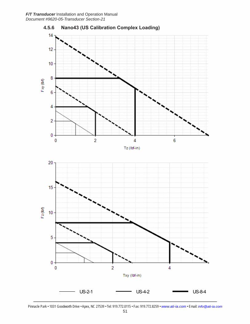
F/T Transducer Installation and Operation ManualDocument #9620-05-Transducer Section-21
Pinnacle Park • 1031 Goodworth Drive • Apex, NC 27539 • Tel: 919.772.0115 • Fax: 919.772.8259 • www.ati-ia.com • Email: [email protected] 51
4.5.6 Nano43(USCalibrationComplexLoading)
HelpNano43
US-2-1 US-4-2 US-8-4

F/T Transducer Installation and Operation ManualDocument #9620-05-Transducer Section-21
Pinnacle Park • 1031 Goodworth Drive • Apex, NC 27539 • Tel: 919.772.0115 • Fax: 919.772.8259 • www.ati-ia.com • Email: [email protected] 52
4.5.7 Nano43(SICalibrationComplexLoading)
HelpNano43
SI-9-0.125 SI-18-0.25 SI-36-0.5
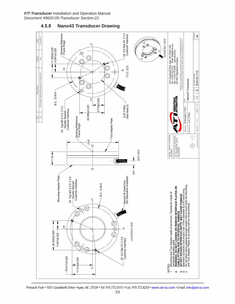
F/T Transducer Installation and Operation ManualDocument #9620-05-Transducer Section-21
Pinnacle Park • 1031 Goodworth Drive • Apex, NC 27539 • Tel: 919.772.0115 • Fax: 919.772.8259 • www.ati-ia.com • Email: [email protected] 53
4.5.8 Nano43 Transducer Drawing
3rd
AN
GLE
PRO
JEC
TION
6.8
47±0
.025
1
1.89
3±0.
025
9.7
79±0
.025
20.
599±
0.02
5
20 T
HR
U(S
ee N
ote
5)
3X T
ap M
3 X
0.5
3.2
Equa
lly S
pace
dC
usto
mer
Inte
rface
2X
2 Sl
ip F
it 3.
4C
usto
mer
Inte
rface
B.C
. 36
.8
TOO
L SI
DE
-Y+Y
-X+XSe
nsin
g R
efer
ence
Fram
e O
rigin
11.
53
43
3.6
SID
E VI
EW
+Z-Z
Sens
ing
Ref
eren
ceFr
ame
Orig
in
Mou
ntin
g Ad
apte
r Pla
te
Tool
Ada
pter
Pla
te
3X T
ap M
3 X
0.5
3.8
Equa
lly S
pace
dC
usto
mer
Inte
rface
7.0
47±0
.025
17.
013±
0.02
5
25.
305±
0.02
5
19.
417±
0.02
5
2X
2 Sl
ip F
it 3.
8C
usto
mer
Inte
rface
B.C
. 36
.8
MO
UNTIN
G S
IDE
+Y
-X+X
-Y
Nan
o43-
R C
able
Exi
t(N
o Al
tern
ativ
e Av
aila
ble)
ISO
MET
RIC
VIE
WN
OTE
S: Mou
ntin
g an
d To
ol A
dapt
er m
ade
of a
lum
inum
, Tra
nsdu
cer m
ade
of
1.ha
rden
ed s
tain
less
ste
el.
WAR
NING
: DO
NO
T LO
OSE
N O
R RE
MO
VE IN
TERF
ACE
PLAT
ES O
R 2.
CABL
E FI
TTIN
G D
UE T
O P
OTE
NTIA
L DA
MAG
E.DO
NO
T EX
CEED
INTE
RFAC
E DE
PTH.
MAY
CAU
SE D
AMAG
E3.
Stan
dard
con
nect
or (n
ot s
how
n) h
as 1
7mm
dia
met
er &
is 6
7.5m
m lo
ng.
4.D
o no
t allo
w it
ems
pass
ing
thro
ugh
cent
er h
ole
to to
uch
both
the
Mou
ntin
g 5.
and
Tool
Ada
pter
Pla
tes
or a
ccur
acy
will
be c
ompr
omis
ed.
Rev.
Des
crip
tion
Initi
ator
Dat
e
06EC
O12
438:
Upd
ate
trans
duce
r con
stru
ctio
nEL
B31
JUL2
014
B1:
11
1RE
VISIO
N
NO
TES:
UN
LESS
OTH
ERW
ISE
SPEC
IFIED
.
DO
NO
T SC
ALE
DRA
WIN
G.
ALL
DIM
ENSI
ON
S A
RE IN
M
ILLIM
ETER
S.
DRA
WN
BY:
CHE
CKE
D B
Y:
B.W
oodl
eif 1
/12/
01
LJH
7/1
5/04
TITLE SC
ALE
SIZE
DRA
WIN
G N
UMBE
R
PRO
JEC
T #SH
EET
O
F 92
30-0
5-11
10---
-----
06
PRO
PERT
Y O
F A
TI IN
DUS
TRIA
L A
UTO
MA
TION
, IN
C. N
OT T
O B
E RE
PRO
DUC
ED IN
AN
Y M
AN
NER
EXC
EPT O
N O
RDER
OR
WITH
PRI
OR
WRI
TTEN
AUT
HORI
ZATIO
N O
F A
TI.
1031
Goo
dwor
th Dr
ive, A
pex,
NC 27
539,
USA
Tel: +
1.919
.772.0
115
Em
ail: in
fo@ati
-ia.co
mFa
x: +1
.919.7
72.82
59
www
.ati-ia
.com
ISO
9001
Reg
ister
ed C
ompa
ny
Nan
o43
Tran
sduc
er

F/T Transducer Installation and Operation ManualDocument #9620-05-Transducer Section-21
Pinnacle Park • 1031 Goodworth Drive • Apex, NC 27539 • Tel: 919.772.0115 • Fax: 919.772.8259 • www.ati-ia.com • Email: [email protected] 54
4.6 Mini27TitaniumSpecifications4.6.1 Mini27 Titanium Physical Properties
Table 4.23—Mini27 Titanium Physical PropertiesSingle-Axis Overload (US)StandardUnits (SI)MetricUnitsFxy ±330 lbf ±1500 NFz ±1000 lbf ±4600 NTxy ±270 inf-lb ±30 NmTz ±360 inf-lb ±40 NmStiffness(Calculated) X-axis&Y-axisforces(Kx,Ky) 1.8x10⁵ lb/in 3.1x10⁷ N/m Z-axisforce(Kz) 3.6x10⁵ lb/in 6.4x10⁷ N/m X-axis&Y-axistorque(Ktx,Kty) 4.0x10⁴ lbf-in/rad 4.5x10³ Nm/rad Z-axistorque(Ktz) 5.8x10⁴ lbf-in/rad 6.5x10³ Nm/rad Resonant Frequency Fx, Fy, Tz N/A N/AFz, Tx, Ty N/A N/APhysicalSpecifications Weight1 0.0736 lb 0.0334 kgDiameter1 1.06 in 27 mmHeight1 0.715 in 18.2 mmNote: 1.Specificationsincludestandardinterfaceplates.
4.6.2 CalibrationSpecifications(excludesCTLcalibrations)Table 4.24—Mini27TitaniumCalibrations(excludesCTLcalibrations)1, 2
Sensor (US)Standard Calibration
Fx,Fy (lbf)
Fz (lbf)
Tx,Ty (lbf-in)
Tz (lbf-in)
Fx,Fy (lbf)
Fz (lbf)
Tx,Ty (lbf-in)
Tz (lbf-in)
Mini27 Titanium US-10-18 10 20 18 10 1/400 3/400 1/400 1/800Mini27 Titanium US-20-36 20 40 36 20 1/200 3/200 1/200 1/400
Sensor (SI)Metric Calibration
Fx,Fy (N)
Fz (N)
Tx,Ty (Nm)
Tz (Nm)
Fx,Fy (N)
Fz (N)
Tx,Ty (Nm)
Tz (Nm)
Mini27 Titanium SI-40-2 40 80 2 1 3/200 3/100 3/8000 1/4000Mini27 Titanium SI-80-4 80 160 4 2 3/100 3/50 3/4000 1/2000
Sensing Ranges Resolution(DAQ,NetF/T)3
Notes: 1. These system resolutions quoted are the effective resolution after dropping four counts of noise. Theeffectiveresolutioncanbeimprovedwithfiltering. 2. Applied loads must be within range in each of the six axes for the F/T sensor to measure correctly. 3. DAQ resolutions are typical for a 16-bit data acquisition system.

F/T Transducer Installation and Operation ManualDocument #9620-05-Transducer Section-21
Pinnacle Park • 1031 Goodworth Drive • Apex, NC 27539 • Tel: 919.772.0115 • Fax: 919.772.8259 • www.ati-ia.com • Email: [email protected] 55
4.6.3 CTLCalibrationSpecificationsTable 4.25— Mini27 Titanium CTL Calibrations1, 2
Sensor (US)Standard Calibration
Fx,Fy (lbf)
Fz (lbf)
Tx,Ty (lbf-in)
Tz (lbf-in)
Fx,Fy (lbf)
Fz (lbf)
Tx,Ty (lbf-in)
Tz (lbf-in)
Mini27 Titanium US-10-18 10 20 18 10 1/200 3/200 1/200 1/400Mini27 Titanium US-20-36 20 40 36 20 1/100 3/100 1/100 1/200
Sensor (SI)Metric Calibration
Fx,Fy (N)
Fz (N)
Tx,Ty (Nm)
Tz (Nm)
Fx,Fy (N)
Fz (N)
Tx,Ty (Nm)
Tz (Nm)
Mini27 Titanium SI-40-2 40 80 2 1 3/100 3/50 3/4000 1/2000Mini27 Titanium SI-80-4 80 160 4 2 3/50 3/25 3/2000 1/1000
Sensing Ranges Resolution(Controller)Notes: 1. CTL resolutions are typical. System resolutions quoted are the effective resolution after dropping eight countsofnoise.Theeffectiveresolutioncanbeimprovedwithfiltering. 2. Applied loads must be within range in each of the six axes for the F/T sensor to measure correctly.
4.6.4 Analog Output
Table 4.26— Mini27 Titanium Analog Output
Sensor (US)Standard Calibration
Fx,Fy (lbf)
Fz (lbf)
Tx,Ty,Tz (lbf-in)
Fx,Fy (lbf/V)
Fz (lbf/V)
Tx,Ty,Tz (lbf-in/V)
Mini27 Titanium US-10-18 ±10 ±20 ±18 1 2 1.8Mini27 Titanium US-20-36 ±20 ±40 ±36 2 4 3.6
Sensor (SI)Metric Calibration
Fx,Fy (N)
Fz (N)
Tx,Ty,Tz (Nmm)
Fx,Fy (N/V)
Fz (N/V)
Tx,Ty,Tz (Nm/V)
Mini27 Titanium SI-40-2 ±40 ±80 ±2 4 8 0.2Mini27 Titanium SI-80-4 ±80 ±160 ±4 8 16 0.4
Analog Output Range Analog±10VSensitivity1
Notes: 1. ±5V Sensitivity values are double the listed ±10V Sensitivity values.
4.6.5 CountsValueTable 4.27—CountsValue
Sensor Calibration Fx,Fy,Fz (/lbf)
Tx,Ty,Tz (/lbf-in)
Fx,Fy,Fz (/N)
Tx,Ty,Tz (/Nm)
Mini27 Titanium US-1–18/SI-40–2 3200 3200 800 32000Mini27 Titanium US-20–36/SI-80–4 1600 1600 400 16000Mini27 Titanium Tool Transform Factor 0.01 in/lbf 0.25 mm/N
CountsValue–Standard(US) CountsValue–Metric(SI)
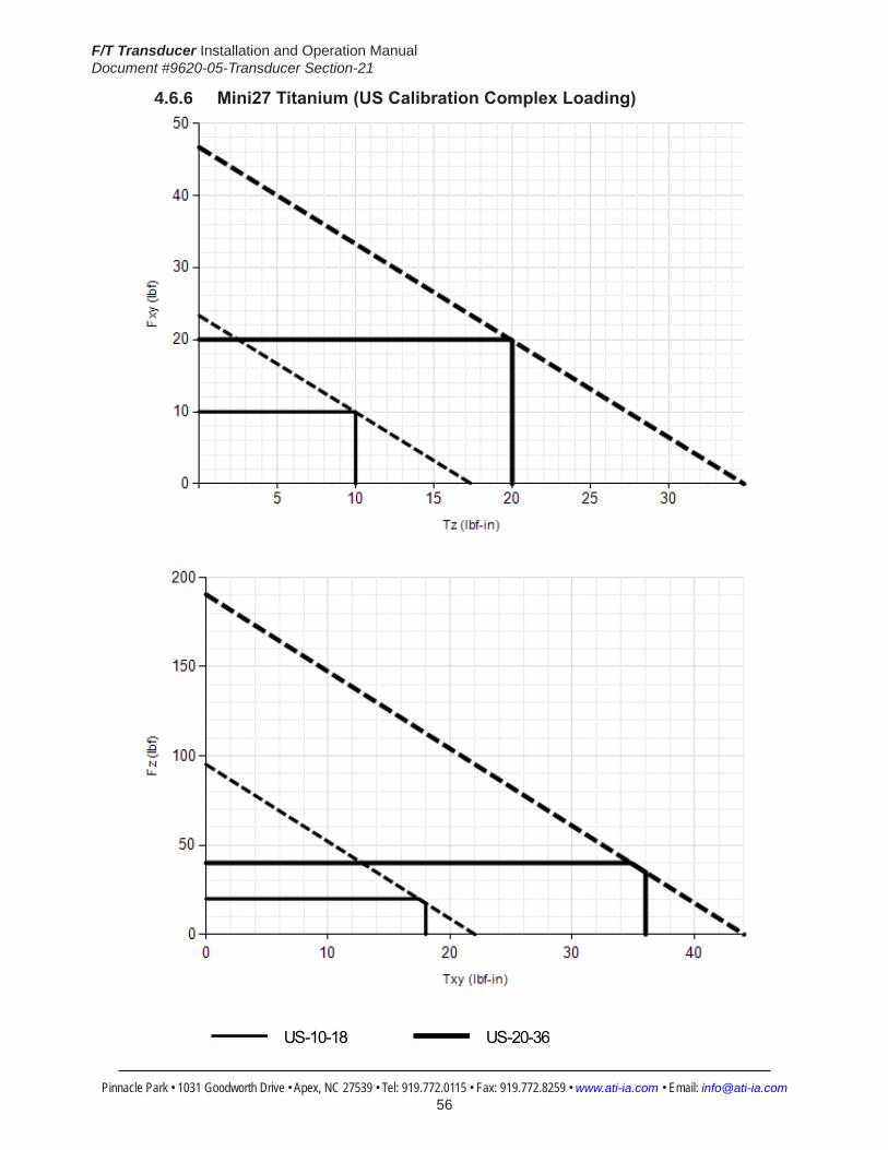
F/T Transducer Installation and Operation ManualDocument #9620-05-Transducer Section-21
Pinnacle Park • 1031 Goodworth Drive • Apex, NC 27539 • Tel: 919.772.0115 • Fax: 919.772.8259 • www.ati-ia.com • Email: [email protected] 56
4.6.6 Mini27Titanium(USCalibrationComplexLoading)
HelpMini27 Titanium
US-10-18 US-20-36

F/T Transducer Installation and Operation ManualDocument #9620-05-Transducer Section-21
Pinnacle Park • 1031 Goodworth Drive • Apex, NC 27539 • Tel: 919.772.0115 • Fax: 919.772.8259 • www.ati-ia.com • Email: [email protected] 57
4.6.7 Mini27Titanium(SICalibrationComplexLoading)
HelpMini27 Titanium
SI-40-2 SI-80-4

F/T Transducer Installation and Operation ManualDocument #9620-05-Transducer Section-21
Pinnacle Park • 1031 Goodworth Drive • Apex, NC 27539 • Tel: 919.772.0115 • Fax: 919.772.8259 • www.ati-ia.com • Email: [email protected] 58
4.6.8 Mini27 Titanium Transducer Drawing
3rd
AN
GLE
PRO
JEC
TION
9.5
69±0
.025
16.
574±
0.02
5
18°
36°
Typ
.
6X T
ap M
3X0.
5 5
.0Pa
irs E
qual
ly S
pace
dC
usto
mer
Inte
rface
(See
Not
e 3)
B.C
.22
.1
11.
049±
0.02
5
2X
2 Sl
ip F
it 3
.8C
usto
mer
Inte
rface
+Y-Y
-X+X
MO
UN
TIN
G S
IDE
18.
2
6.4
6
.4
27
2.1
5.2
3.3
-Z+Z
Tool
Adap
ter
Plat
e
Mou
ntin
gAd
apte
rPl
ate
Sens
ing
Ref
eren
ceFr
ame
Orig
in
SID
E VI
EW
18°
36°
Typ
.
5.5
25±0
.025
19.
137±
0.02
5
9.5
69±0
.025
6X T
ap M
3X0.
5 5
.0Pa
irs E
qual
ly S
pace
dC
usto
mer
Inte
rface
(See
Not
e 3)
2X
2 S
lip F
it 3
.8C
usto
mer
Inte
rface
B.C
.22
.1
30°
15
+Y-Y
-X+X
Sens
ing
Ref
eren
ceFr
ame
Orig
in
TOO
L SI
DE
MIN
I27T
I-A IS
OM
ETR
IC V
IEW
MIN
I27T
I-R IS
OM
ETR
IC V
IEW
Not
es: Mat
eria
l: Tr
ansd
ucer
, Mou
ntin
g an
d To
ol A
dapt
er m
ade
of T
itani
um T
i-6AI
-4V
1.G
rade
5.
WA
RN
ING
: DO
NO
T LO
OSE
N O
R R
EMO
VE IN
TER
FAC
E PL
ATE
S O
R C
AB
LE
2.FI
TTIN
G D
UE
TO P
OTE
NTI
AL
DA
MA
GE
DO
NO
T EX
CEE
D IN
TER
FAC
E D
EPTH
, MA
Y C
AU
SE D
AM
AG
E.3.
Stan
dard
con
nect
or (n
ot s
how
n) h
as 1
7mm
dia
met
er a
nd is
67.
5mm
long
.4.
Min
i27T
i-R C
able
Exit
(Alte
rnat
e)
Rev.
Des
crip
tion
Initi
ator
Dat
e
04EC
O 1
1406
: Cor
rect
ed Is
omet
ric v
iew
title
Min
i27T
I-RLJ
H9/
17/1
3
B3:
11
1RE
VISIO
N
NO
TES:
UN
LESS
OTH
ERW
ISE
SPEC
IFIED
.
DO
NO
T SC
ALE
DRA
WIN
G.
ALL
DIM
ENSI
ON
S A
RE IN
M
ILLIM
ETER
S.
DRA
WN
BY:
CHE
CKE
D B
Y:
J. W
alse
r 02/
27/2
012
R. C
ham
bers
02/
28/1
2
TITLE SC
ALE
SIZE
DRA
WIN
G N
UMBE
R
PRO
JEC
T #SH
EET
O
F 92
30-0
5-14
2010
0429
-104
PRO
PERT
Y O
F A
TI IN
DUS
TRIA
L A
UTO
MA
TION
, IN
C. N
OT T
O B
E RE
PRO
DUC
ED IN
AN
Y M
AN
NER
EXC
EPT O
N O
RDER
OR
WITH
PRI
OR
WRI
TTEN
AUT
HORI
ZATIO
N O
F A
TI.
1031
Goo
dwor
th Dr
ive, A
pex,
NC 27
539,
USA
Tel: +
1.919
.772.0
115
Em
ail: in
fo@ati
-ia.co
mFa
x: +1
.919.7
72.82
59
www
.ati-ia
.com
ISO
9001
Reg
ister
ed C
ompa
ny
Tita
nium
Min
i27
Tran
sduc
er

F/T Transducer Installation and Operation ManualDocument #9620-05-Transducer Section-21
Pinnacle Park • 1031 Goodworth Drive • Apex, NC 27539 • Tel: 919.772.0115 • Fax: 919.772.8259 • www.ati-ia.com • Email: [email protected] 59
4.7 Mini40Specifications(IncludesIP65/IP68Versions)4.7.1 Mini40 Physical Properties
Table4.28—Mini40 Physical PropertiesSingle-Axis Overload (US)StandardUnits (SI)MetricUnitsFxy ±180 lbf ±810 NFz ±530 lbf ±2400 NTxy ±170 inf-lb ±19 NmTz ±180 inf-lb ±20 NmStiffness(Calculated) X-axis&Y-axisforces(Kx,Ky) 6.1x10⁴ lb/in 1.1x10⁷ N/m Z-axisforce(Kz) 1.2x10⁵ lb/in 2.0x10⁷ N/m X-axis&Y-axistorque(Ktx,Kty) 2.5x10⁴ lbf-in/rad 2.8x10³ Nm/rad Z-axistorque(Ktz) 3.6x10⁴ lbf-in/rad 4.0x10³ Nm/rad Resonant Frequency Fx, Fy, Tz 3200 Hz 3200 HzFz, Tx, Ty 4900 Hz 4900 HzPhysicalSpecifications Weight1 0.11 lb 0.0499 kgDiameter1 1.57 in 40 mmHeight1 0.482 in 12.2 mmNote: 1.Specificationsincludestandardinterfaceplates.
4.7.2 Mini40IP65/IP68PhysicalPropertiesTable 4.29—Mini40IP65/IP68PhysicalProperties
Single-Axis Overload (US)StandardUnits (SI)MetricUnitsFxy ±180 lbf ±810 NFz ±530 lbf ±2400 NTxy ±170 inf-lb ±19 NmTz ±180 inf-lb ±20 NmStiffness(Calculated) X-axis&Y-axisforces(Kx,Ky) 6.1x10⁴ lb/in 1.1x10⁷ N/m Z-axisforce(Kz) 1.2x10⁵ lb/in 2.0x10⁷ N/m X-axis&Y-axistorque(Ktx,Kty) 2.5x10⁴ lbf-in/rad 2.8x10³ Nm/rad Z-axistorque(Ktz) 3.6x10⁴ lbf-in/rad 4.0x10³ Nm/rad Resonant Frequency Fx, Fy, Tz 1400 Hz 1400 HzFz, Tx, Ty 1300 Hz 1300 HzPhysicalSpecifications Weight1 0.6 lb 0.272 kgDiameter1 2.1 in 53.3 mmHeight1 0.83 in 21.1 mmNote: 1.Specificationsincludestandardinterfaceplates.

F/T Transducer Installation and Operation ManualDocument #9620-05-Transducer Section-21
Pinnacle Park • 1031 Goodworth Drive • Apex, NC 27539 • Tel: 919.772.0115 • Fax: 919.772.8259 • www.ati-ia.com • Email: [email protected] 60
CAUTION: When submerged, IP68 transducers exhibit a decrease in Fz range related to the submersion depth. This loss is the result of pressure-induced preloading on the transducer. The preload can be masked by biasing the transducer at the depth prior to applying the load to be measured. The following estimates are for room temperature fresh water at sea level.
Submersion DepthIP68Mini40 US MetricFz preload at 4 m depth 17.0 lb 75.5 NFz preload at other depths -1.29 lb/ft × depthInFeet -18.9 N/m × depthInMeters
4.7.3 CalibrationSpecifications(excludesCTLcalibrations)Table 4.30—Mini40Calibrations(excludesCTLcalibrations)1, 2
Sensor (US)Standard Calibration
Fx,Fy (lbf)
Fz3 (lbf)
Tx,Ty (lbf-in)
Tz (lbf-in)
Fx,Fy (lbf)
Fz3 (lbf)
Tx,Ty (lbf-in)
Tz (lbf-in)
Mini40 US-5-10 5 15 10 10 1/800 1/400 1/800 1/800Mini40 US-10-20 10 30 20 20 1/400 1/200 1/400 1/400Mini40 US-20-40 20 60 40 40 1/200 1/100 1/200 1/200
Sensor (SI)Metric Calibration
Fx,Fy (N)
Fz3 (N)
Tx,Ty (Nm)
Tz (Nm)
Fx,Fy (N)
Fz3 (N)
Tx,Ty (Nm)
Tz (Nm)
Mini40 SI-20-1 20 60 1 1 1/200 1/100 1/8000 1/8000Mini40 SI-40-2 40 120 2 2 1/100 1/50 1/4000 1/4000Mini40 SI-80-4 80 240 4 4 1/50 1/25 1/2000 1/2000
Sensing Ranges Resolution(DAQ,NetF/T)4
Notes: 1. These system resolutions quoted are the effective resolution after dropping four counts of noise. Theeffectiveresolutioncanbeimprovedwithfiltering. 2. Applied loads must be within range in each of the six axes for the F/T sensor to measure correctly. 3. For IP68 version see caution on physical properties page. 4. DAQ resolutions are typical for a 16-bit data acquisition system.

F/T Transducer Installation and Operation ManualDocument #9620-05-Transducer Section-21
Pinnacle Park • 1031 Goodworth Drive • Apex, NC 27539 • Tel: 919.772.0115 • Fax: 919.772.8259 • www.ati-ia.com • Email: [email protected] 61
4.7.4 CTLCalibrationSpecificationsTable 4.31— Mini40 CTL Calibrations1, 2
Sensor (US)Standard Calibration
Fx,Fy (lbf)
Fz3 (lbf)
Tx,Ty (lbf-in)
Tz (lbf-in)
Fx,Fy (lbf)
Fz3 (lbf)
Tx,Ty (lbf-in)
Tz (lbf-in)
Mini40 US-5-10 5 15 10 10 1/400 1/200 1/400 1/400Mini40 US-10-20 10 30 20 20 1/200 1/100 1/200 1/200Mini40 US-20-40 20 60 40 40 1/100 1/50 1/100 1/100
Sensor (SI)Metric Calibration
Fx,Fy (N)
Fz3 (N)
Tx,Ty (Nm)
Tz (Nm)
Fx,Fy (N)
Fz3 (N)
Tx,Ty (Nm)
Tz (Nm)
Mini40 SI-20-1 20 60 1 1 1/100 1/50 1/4000 1/4000Mini40 SI-40-2 40 120 2 2 1/50 1/25 1/2000 1/2000Mini40 SI-80-4 80 240 4 4 1/25 2/25 1/1000 1/1000
Sensing Ranges Resolution(Controller)Notes: 1. CTL resolutions are typical. System resolutions quoted are the effective resolution after dropping eight countsofnoise.Theeffectiveresolutioncanbeimprovedwithfiltering. 2. Applied loads must be within range in each of the six axes for the F/T sensor to measure correctly. 3. For IP68 version see caution on physical properties page.
4.7.5 Analog OutputTable 4.32— Mini40 Analog Output
Sensor (US)Standard Calibration
Fx,Fy (lbf)
Fz2 (lbf)
Tx,Ty,Tz (lbf-in)
Fx,Fy (lbf/V)
Fz2 (lbf/V)
Tx,Ty,Tz (lbf-in/V)
Mini40 US-5-10 ±5 ±15 ±10 0.5 1.5 1Mini40 US-10-20 ±10 ±30 ±20 1 3 2Mini40 US-20-40 ±20 ±60 ±40 2 6 4
Sensor (SI)Metric Calibration
Fx,Fy (N)
Fz2 (N)
Tx,Ty,Tz (Nmm)
Fx,Fy (N/V)
Fz2 (N/V)
Tx,Ty,Tz (Nm/V)
Mini40 SI-20-1 ±20 ±60 ±1 2 6 0.1Mini40 SI-40-2 ±40 ±120 ±2 4 12 0.2Mini40 SI-80-4 ±80 ±240 ±4 8 24 0.4
Analog Output Range Analog±10VSensitivity1
Notes: 1. ±5V Sensitivity values are double the listed ±10V Sensitivity values. 2. For IP68 version see caution on physical properties page.
4.7.6 CountsValueTable 4.33—CountsValue
Sensor Calibration Fx,Fy,Fz (/lbf)
Tx,Ty,Tz (/lbf-in)
Fx,Fy,Fz (/N)
Tx,Ty,Tz (/Nm)
Mini40 US-5–10/SI-20–1 3200 3200 800 32000Mini40 US-10–20/SI-40–2 1600 1600 400 16000Mini40 US-20–40/SI-80-4 800 800 200 8000Mini40 Tool Transform Factor 0.01 in/lbf 0.25 mm/N
CountsValue–Standard(US) CountsValue–Metric(SI)

F/T Transducer Installation and Operation ManualDocument #9620-05-Transducer Section-21
Pinnacle Park • 1031 Goodworth Drive • Apex, NC 27539 • Tel: 919.772.0115 • Fax: 919.772.8259 • www.ati-ia.com • Email: [email protected] 62
4.7.7 Mini40(USCalibrationComplexLoading)(IncludesIP65/IP68)1
HelpMini40
US-5-10 US-10-20 US-20-40
Note: 1. For IP68 version see caution on physical properties page.

F/T Transducer Installation and Operation ManualDocument #9620-05-Transducer Section-21
Pinnacle Park • 1031 Goodworth Drive • Apex, NC 27539 • Tel: 919.772.0115 • Fax: 919.772.8259 • www.ati-ia.com • Email: [email protected] 63
4.7.8 Mini40(SICalibrationComplexLoading)(IncludesIP65/IP68)1
HelpMini40
SI-20-1 SI-40-2 SI-80-4
Note: 1. For IP68 version see caution on physical properties page.
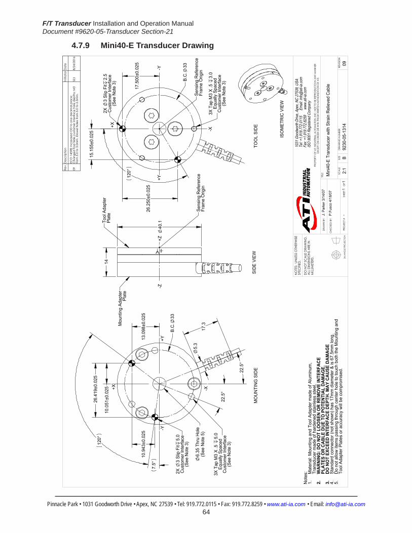
F/T Transducer Installation and Operation ManualDocument #9620-05-Transducer Section-21
Pinnacle Park • 1031 Goodworth Drive • Apex, NC 27539 • Tel: 919.772.0115 • Fax: 919.772.8259 • www.ati-ia.com • Email: [email protected] 64
4.7.9 Mini40-E Transducer Drawing
3rd
AN
GLE
PRO
JEC
TION
14
40
.1
Mou
ntin
g Ad
apte
rPl
ate
Tool
Ada
pter
Plat
e
Sens
ing
Ref
eren
ceFr
ame
Orig
in
SID
E VI
EW
17.
500±
0.02
5
26.
250±
0.02
5
15.
155±
0.02
5
120
°
B.C
.33
Sens
ing
Ref
eren
ceFr
ame
Orig
in
3X T
ap M
3 X
.5
3.0
Equa
lly S
pace
dC
usto
mer
Inte
rface
(See
Not
e 3)
TOO
L SI
DE
2X
3 Sl
ip F
it2.
5C
usto
mer
Inte
rface
(See
Not
e 3)
ISO
MET
RIC
VIE
W
26.
419±
0.02
5
13.
098±
0.02
5
10.
051±
0.02
5
10.
943±
0.02
5
5.
3 6.
35 T
hru
Hol
e(S
ee N
ote
5)
22.
5°
22.
5°
17.
3
7.5
°
120
°
B.C
.33
3X T
ap M
3 X
.5
5.0
Equa
lly S
pace
dC
usto
mer
Inte
rface
(See
Not
e 3)
+X
+Y
-X
-Y+Z
-Z+Y
-Y
-X
+X
MO
UN
TIN
G S
IDE
2X
3 Sl
ip F
it5.
0C
usto
mer
Inte
rface
(See
Not
e 3)
Not
es: Mat
eria
l: M
ount
ing
and
Tool
Ada
pter
mad
e of
Alu
min
um,
1.Tr
ansd
ucer
mad
e of
har
dene
d st
ainl
ess
stee
l.W
AR
NIN
G: D
O N
OT
LOO
SEN
OR
REM
OVE
INTE
RFA
CE
2.PL
ATE
S O
R C
AB
LE D
UE
TO P
OTE
NTI
AL
DA
MA
GE.
DO
NO
T EX
CEE
D IN
TER
FAC
E D
EPTH
. MA
Y C
AU
SE D
AM
AG
E3.
Stan
dard
con
nect
or (n
ot s
how
n) h
as 1
7mm
dia
met
er &
is 6
7.5m
m lo
ng.
4.D
o no
t allo
w it
ems
pass
ing
thro
ugh
cent
er h
ole
to to
uch
both
the
Mou
ntin
g an
d5.
Tool
Ada
pter
Pla
tes
or a
ccur
acy
will
be c
ompr
omis
ed.
Rev.
Des
crip
tion
Initi
ator
Dat
e
09EC
O 1
4598
; Inc
reas
ed O
D to
one
dec
imal
pla
ce;
Cha
nged
Tool
Sid
e cu
stom
er in
terfa
ce h
ole
dept
hs: M
3 fro
m 5
.0 to
3.0
mm
, Dow
el h
oles
from
5.0
to 2
.5m
m.
SZJ
8/24
/201
6
B2:
11
1RE
VISIO
N
NO
TES:
UN
LESS
OTH
ERW
ISE
SPEC
IFIED
.
DO
NO
T SC
ALE
DRA
WIN
G.
ALL
DIM
ENSI
ON
S A
RE IN
M
ILLIM
ETER
S.
DRA
WN
BY:
CHE
CKE
D B
Y:
J. P
arke
r 3/1
4/07
P.Fu
sco
4/18
/07
TITLE SC
ALE
SIZE
DRA
WIN
G N
UMBE
R
PRO
JEC
T #SH
EET
O
F 92
30-0
5-13
14-
09
PRO
PERT
Y O
F A
TI IN
DUS
TRIA
L A
UTO
MA
TION
, IN
C. N
OT T
O B
E RE
PRO
DUC
ED IN
AN
Y M
AN
NER
EXC
EPT O
N O
RDER
OR
WITH
PRI
OR
WRI
TTEN
AUT
HORI
ZATIO
N O
F A
TI.
1031
Goo
dwor
th Dr
ive, A
pex,
NC 27
539,
USA
Tel: +
1.919
.772.0
115
Em
ail: in
fo@ati
-ia.co
mFa
x: +1
.919.7
72.82
59
www
.ati-ia
.com
ISO
9001
Reg
ister
ed C
ompa
ny
Min
i40-
E Tr
ansd
ucer
with
Stra
in R
elie
ved
Cab
le
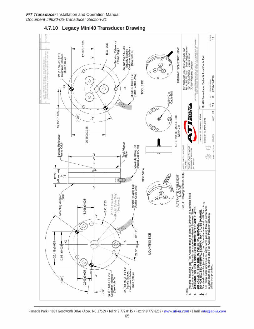
F/T Transducer Installation and Operation ManualDocument #9620-05-Transducer Section-21
Pinnacle Park • 1031 Goodworth Drive • Apex, NC 27539 • Tel: 919.772.0115 • Fax: 919.772.8259 • www.ati-ia.com • Email: [email protected] 65
4.7.10 Legacy Mini40 Transducer Drawing
3rd
AN
GLE
PRO
JEC
TION
26.
250±
0.02
5 15.
155±
0.02
5
17.
500±
0.02
5
120
°
B.C
. 33
TOO
L SI
DE
-Y+Y
-X+X
Min
i40-
R C
able
Exi
t(R
adia
l Cab
le O
nly)
Sens
ing
Ref
eren
ceFr
ame
Orig
in
3X T
ap M
3 X.
53.
0Eq
ually
Spa
ced
Cus
tom
er In
terfa
ce(S
ee N
ote
3)
2X
3 Sl
ip F
it2.
5C
usto
mer
Inte
rface
(See
Not
e 3)
12.2
7(-R
and
-A)
14 (-E)
40
.1
SID
E VI
EW
+Z-Z
Mou
ntin
g Ad
apte
rPl
ate
Tool
Ada
pter
Pl
ate
Min
i40-
R C
able
Exi
t(R
adia
l Cab
le O
nly)
Sens
ing
Ref
eren
ceFr
ame
Orig
in
13.
098±
0.02
5
10.
051±
0.02
5
26.
419±
0.02
5
6.35
Thr
u H
ole
(Rad
ial C
able
Onl
y)(S
ee N
ote
5)
10.
943±
0.02
5
22.5
°30
° (-R
)
B.C
. 33
120
°
7.5
°
MO
UN
TIN
G S
IDE
3X T
ap M
3 X
.55.
0Eq
ually
Spa
ced
Cus
tom
er In
terfa
ce(S
ee N
ote
3)
+Y
-X+X
-Y
Min
i40-
R C
able
Exi
t(R
adia
l Cab
le O
nly)
2X
3 Sl
ip F
it2.
5C
usto
mer
Inte
rface
(See
Not
e 3)
ALTE
RN
ATE
CAB
LE E
XIT
MIN
I40-
A
MIN
I40-
AC
able
Exi
t
ALTE
RN
ATE
CAB
LE E
XIT
MIN
I40-
ESe
e -E
Dra
win
g 92
30-0
5-13
14 M
INI4
0-R
ISO
MET
RIC
VIE
W
Not
es: M
ater
ial:
Mou
ntin
g an
d To
ol A
dapt
er m
ade
of e
ither
Alu
min
um o
r Sta
inle
ss S
teel
1.(c
usto
mer
spe
cifie
d). T
rans
duce
r mad
e of
har
dene
d St
ainl
ess
Stee
l.W
ARNI
NG: D
O N
OT
LOO
SEN
OR
REM
OVE
INTE
RFAC
E PL
ATES
2.
OR
CABL
E FI
TTIN
G D
UE T
O P
OTE
NTIA
L DA
MAG
E.DO
NO
T EX
CEED
INTE
RFAC
E DE
PTH,
MAY
CAU
SE D
AMAG
E.3.
Stan
dard
con
nect
or (n
ot s
how
n) h
as 1
7mm
dia
met
er a
nd is
67.
5mm
long
.4.
For R
adia
l cab
le u
nits
: Do
not a
llow
item
s pa
ssin
g th
roug
h ce
nter
hol
e 5.
to to
uch
both
the
Mou
ntin
g an
d To
ol A
dapt
er P
late
s or
acc
urac
y w
ill be
com
prom
ised
.
Rev.
Des
crip
tion
Initi
ator
Dat
e
11EC
O 1
4598
; Inc
reas
ed O
D to
one
dec
imal
pla
ce.
Rem
oved
cab
le e
xit d
imen
sion
for -
E co
nfig
urat
ion
and
adde
d no
te to
see
-E d
raw
ing
for A
ltern
ativ
e C
able
Exit
.SZ
J8/
24/2
016
B2:
11
1RE
VISIO
N
NO
TES:
UN
LESS
OTH
ERW
ISE
SPEC
IFIED
.
DO
NO
T SC
ALE
DRA
WIN
G.
ALL
DIM
ENSI
ON
S A
RE IN
M
ILLIM
ETER
S.
DRA
WN
BY:
CHE
CKE
D B
Y:
D. S
wan
son
3/9/
06
D. P
erry
3/9
/06
TITLE SC
ALE
SIZE
DRA
WIN
G N
UMBE
R
PRO
JEC
T #SH
EET
O
F 92
30-0
5-12
7811
PRO
PERT
Y O
F A
TI IN
DUS
TRIA
L A
UTO
MA
TION
, IN
C. N
OT T
O B
E RE
PRO
DUC
ED IN
AN
Y M
AN
NER
EXC
EPT O
N O
RDER
OR
WITH
PRI
OR
WRI
TTEN
AUT
HORI
ZATIO
N O
F A
TI.
1031
Goo
dwor
th Dr
ive, A
pex,
NC 27
539,
USA
Tel: +
1.919
.772.0
115
Em
ail: in
fo@ati
-ia.co
mFa
x: +1
.919.7
72.82
59
www
.ati-ia
.com
ISO
9001
Reg
ister
ed C
ompa
ny
Min
i40
Tran
sduc
er R
adia
l & A
xial
Cab
le E
xit

F/T Transducer Installation and Operation ManualDocument #9620-05-Transducer Section-21
Pinnacle Park • 1031 Goodworth Drive • Apex, NC 27539 • Tel: 919.772.0115 • Fax: 919.772.8259 • www.ati-ia.com • Email: [email protected] 66
4.7.11 Mini40IP65/IP68TransducerDrawing
3rd
AN
GLE
PRO
JEC
TION
15.
155±
0.02
5
26.
250±
0.02
5
2X3
Slip
Fit
4.5
Cus
tom
er In
terfa
ce
B.C
.33
3X T
ap M
3X0.
5 4
.5E
qual
ly S
pace
dC
usto
mer
Inte
rface
17.
500±
0.02
5
Sen
sing
Ref
eren
ceFr
ame
Orig
in
+X -X
-Y+Y
TOO
L S
IDE
53
.3
21.
1
38
.1
Sen
sing
Ref
eren
ceFr
ame
Orig
in
Tool
Ada
pter
Pla
teM
ount
ing
Ada
pter
Pla
te
+Z-Z
SID
E V
IEW
Min
i40-
R C
able
Exi
t(S
tand
ard)
22.
5°
10.
051±
0.02
5
26.
419±
0.02
5
13.
098±
0.02
5 1
0.94
3±0.
025
3X T
ap M
3X0.
5 4
.5E
qual
ly S
pace
dC
usto
mer
Inte
rface
2X3
Slip
Fit
4.5
Cus
tom
er In
terfa
ce
33
7.
4
36.3
MA
X
30°
MO
UN
TIN
G S
IDE
+Y-Y
+X -X
Min
i40-
R C
able
Exi
t(S
tand
ard)
MIN
I40-
R IS
OM
ETR
IC V
IEW
ALT
ER
NA
TE C
AB
LE E
XIT
MIN
I40-
A
Not
es:
Mat
eria
l: S
tain
less
Ste
el.
1.To
ol a
nd M
ount
ing
Ada
pter
s ha
ve M
3 ta
pped
hol
es a
nd 3
mm
2.
dow
el p
in h
oles
for i
nter
faci
ng.
WA
RN
ING
: DO
NO
T LO
OSE
N O
R R
EMO
VE IN
TER
FAC
E3.
PLA
TES
DU
E TO
PO
TEN
TIA
L D
AM
AG
E.S
tand
ard
conn
ecto
r (no
t sho
wn)
has
17m
m d
iam
eter
& is
67.
5mm
long
. 4.
Cab
le is
IP65
/IP68
rate
d on
ly a
t tra
nsdu
cer e
nd.
5.
Min
i40-
A C
able
Exi
t(A
ltern
ate)
Rev.
Des
crip
tion
Initi
ator
Dat
e
03EC
O 1
4323
; Inc
reas
ed to
lera
nce
on d
owel
hol
e po
sitio
ns
from
.0
13 to
.0
25SZ
J3/
28/2
016
B3:
21
1RE
VISI
ON
NO
TES:
UN
LESS
OTH
ERW
ISE
SPEC
IFIE
D.
DO
NO
T SC
ALE
DRA
WIN
G.
ALL
DIM
ENSI
ON
S A
RE IN
M
ILLIM
ETER
S.
DRA
WN
BY:
CHE
CKE
D B
Y:
R. C
ham
bers
3/9
/12
J. W
alse
r 3/9
/12
TITLE SC
ALE
SIZE
DRA
WIN
G N
UMBE
R
PRO
JEC
T #
SHEE
T
O
F 92
30-0
5-14
2111
0516
-203
PRO
PERT
Y O
F A
TI IN
DUS
TRIA
L A
UTO
MA
TION
, IN
C. N
OT
TO B
E RE
PRO
DUC
ED IN
AN
Y M
AN
NER
EXC
EPT
ON
ORD
ER O
R W
ITH P
RIO
R W
RITT
EN A
UTHO
RIZA
TION
OF
ATI.
1031
Goo
dwor
th Dr
ive, A
pex,
NC 27
539,
USA
Tel: +
1.919
.772.0
115
Em
ail: in
fo@ati
-ia.co
mFa
x: +1
.919.7
72.82
59
www
.ati-ia
.com
ISO
9001
Reg
ister
ed C
ompa
ny
IP65
/IP68
Min
i40
Tran
sduc
er
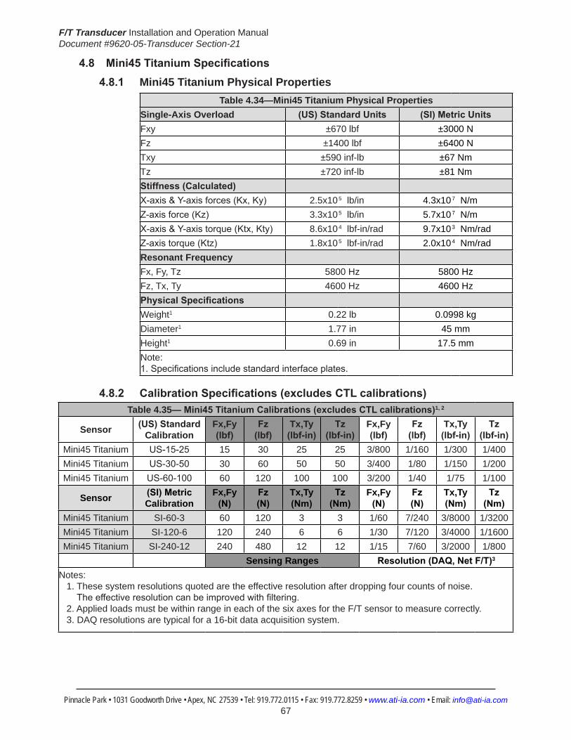
F/T Transducer Installation and Operation ManualDocument #9620-05-Transducer Section-21
Pinnacle Park • 1031 Goodworth Drive • Apex, NC 27539 • Tel: 919.772.0115 • Fax: 919.772.8259 • www.ati-ia.com • Email: [email protected] 67
4.8 Mini45TitaniumSpecifications4.8.1 Mini45 Titanium Physical Properties
Table 4.34—Mini45 Titanium Physical PropertiesSingle-Axis Overload (US)StandardUnits (SI)MetricUnitsFxy ±670 lbf ±3000 NFz ±1400 lbf ±6400 NTxy ±590 inf-lb ±67 NmTz ±720 inf-lb ±81 NmStiffness(Calculated) X-axis&Y-axisforces(Kx,Ky) 2.5x10⁵ lb/in 4.3x10⁷ N/m Z-axisforce(Kz) 3.3x10⁵ lb/in 5.7x10⁷ N/m X-axis&Y-axistorque(Ktx,Kty) 8.6x10⁴ lbf-in/rad 9.7x10³ Nm/rad Z-axistorque(Ktz) 1.8x10⁵ lbf-in/rad 2.0x10⁴ Nm/rad Resonant Frequency Fx, Fy, Tz 5800 Hz 5800 HzFz, Tx, Ty 4600 Hz 4600 HzPhysicalSpecifications Weight1 0.22 lb 0.0998 kgDiameter1 1.77 in 45 mmHeight1 0.69 in 17.5 mmNote: 1.Specificationsincludestandardinterfaceplates.
4.8.2 CalibrationSpecifications(excludesCTLcalibrations)Table 4.35—Mini45TitaniumCalibrations(excludesCTLcalibrations)1, 2
Sensor (US)Standard Calibration
Fx,Fy (lbf)
Fz (lbf)
Tx,Ty (lbf-in)
Tz (lbf-in)
Fx,Fy (lbf)
Fz (lbf)
Tx,Ty (lbf-in)
Tz (lbf-in)
Mini45 Titanium US-15-25 15 30 25 25 3/800 1/160 1/300 1/400Mini45 Titanium US-30-50 30 60 50 50 3/400 1/80 1/150 1/200Mini45 Titanium US-60-100 60 120 100 100 3/200 1/40 1/75 1/100
Sensor (SI)Metric Calibration
Fx,Fy (N)
Fz (N)
Tx,Ty (Nm)
Tz (Nm)
Fx,Fy (N)
Fz (N)
Tx,Ty (Nm)
Tz (Nm)
Mini45 Titanium SI-60-3 60 120 3 3 1/60 7/240 3/8000 1/3200Mini45 Titanium SI-120-6 120 240 6 6 1/30 7/120 3/4000 1/1600Mini45 Titanium SI-240-12 240 480 12 12 1/15 7/60 3/2000 1/800
Sensing Ranges Resolution(DAQ,NetF/T)3
Notes: 1. These system resolutions quoted are the effective resolution after dropping four counts of noise. Theeffectiveresolutioncanbeimprovedwithfiltering. 2. Applied loads must be within range in each of the six axes for the F/T sensor to measure correctly. 3. DAQ resolutions are typical for a 16-bit data acquisition system.

F/T Transducer Installation and Operation ManualDocument #9620-05-Transducer Section-21
Pinnacle Park • 1031 Goodworth Drive • Apex, NC 27539 • Tel: 919.772.0115 • Fax: 919.772.8259 • www.ati-ia.com • Email: [email protected] 68
4.8.3 CTLCalibrationSpecificationsTable 4.36— Mini45 Titanium CTL Calibrations1, 2
Sensor (US)Standard Calibration
Fx,Fy (lbf)
Fz (lbf)
Tx,Ty (lbf-in)
Tz (lbf-in)
Fx,Fy (lbf)
Fz (lbf)
Tx,Ty (lbf-in)
Tz (lbf-in)
Mini45 Titanium US-15-25 15 30 25 25 3/400 1/80 1/150 1/200Mini45 Titanium US-30-50 30 60 50 50 3/200 1/40 1/75 1/100Mini45 Titanium US-60-100 60 120 100 100 3/100 1/20 2/75 1/50
Sensor (SI)Metric Calibration
Fx,Fy (N)
Fz (N)
Tx,Ty (Nm)
Tz (Nm)
Fx,Fy (N)
Fz (N)
Tx,Ty (Nm)
Tz (Nm)
Mini45 Titanium SI-60-3 60 120 3 3 1/30 7/120 3/4000 1/1600Mini45 Titanium SI-120-6 120 240 6 6 1/15 7/60 3/2000 1/800Mini45 Titanium SI-240-12 240 480 12 12 2/15 7/30 3/1000 1/400
Sensing Ranges Resolution(Controller)Notes: 1. CTL resolutions are typical. System resolutions quoted are the effective resolution after dropping eight countsofnoise.Theeffectiveresolutioncanbeimprovedwithfiltering. 2. Applied loads must be within range in each of the six axes for the F/T sensor to measure correctly.
4.8.4 Analog Output
Table 4.37— Mini45 Titanium Analog Output
Sensor (US)Standard Calibration
Fx,Fy (lbf)
Fz (lbf)
Tx,Ty,Tz (lbf-in)
Fx,Fy (lbf/V)
Fz (lbf/V)
Tx,Ty,Tz (lbf-in/V)
Mini45 Titanium US-15-25 ±15 ±30 ±25 1.5 3 2.5Mini45 Titanium US-30-50 ±30 ±60 ±50 3 6 5Mini45 Titanium US-60-100 ±60 ±120 ±100 6 12 10
Sensor (SI)Metric Calibration
Fx,Fy (N)
Fz (N)
Tx,Ty,Tz (Nmm)
Fx,Fy (N/V)
Fz (N/V)
Tx,Ty,Tz (Nm/V)
Mini45 Titanium SI-60-3 ±60 ±120 ±3 6 12 0.3Mini45 Titanium SI-120-6 ±120 ±240 ±6 12 24 0.6Mini45 Titanium SI-240-12 ±240 ±480 ±12 24 48 1.2
Analog Output Range Analog±10VSensitivity1
Notes: 1. ±5V Sensitivity values are double the listed ±10V Sensitivity values.
4.8.5 CountsValueTable4.38—CountsValue
Sensor Calibration Fx,Fy,Fz (/lbf)
Tx,Ty,Tz (/lbf-in)
Fx,Fy,Fz (/N)
Tx,Ty,Tz (/Nm)
Mini45 Titanium US-15-25/SI-60-3 640 704 128 6016Mini45 Titanium US-30-50/SI-120-6 320 352 64 3008Mini45 Titanium US-60-100/SI-240-12 160 176 32 1504Mini45 Titanium Tool Transform Factor 0.009091 in/lbf 0.21277 mm/N
CountsValue–Standard(US) CountsValue–Metric(SI)

F/T Transducer Installation and Operation ManualDocument #9620-05-Transducer Section-21
Pinnacle Park • 1031 Goodworth Drive • Apex, NC 27539 • Tel: 919.772.0115 • Fax: 919.772.8259 • www.ati-ia.com • Email: [email protected] 69
4.8.6 Mini45Titanium(USCalibrationComplexLoading)
HelpMini45 Titanium
US-15-25 US-30-50 US-60-100

F/T Transducer Installation and Operation ManualDocument #9620-05-Transducer Section-21
Pinnacle Park • 1031 Goodworth Drive • Apex, NC 27539 • Tel: 919.772.0115 • Fax: 919.772.8259 • www.ati-ia.com • Email: [email protected] 70
4.8.7 Mini45Titanium(SICalibrationComplexLoading)
HelpMini45 Titanium
SI-60-3 SI-120-6 SI-240-12

F/T Transducer Installation and Operation ManualDocument #9620-05-Transducer Section-21
Pinnacle Park • 1031 Goodworth Drive • Apex, NC 27539 • Tel: 919.772.0115 • Fax: 919.772.8259 • www.ati-ia.com • Email: [email protected] 71
4.8.8 Mini45 Titanium Axial Exit Transducer Drawing
3rd
AN
GLE
PRO
JEC
TION
B.C
.39
.2
10°
20
°Ty
p
6X T
ap M
3X0.
5 5
Pairs
Equ
ally
Spa
ced
Cus
tom
er In
terfa
ce(S
ee N
ote
3)
9.53
89.
512
3C
usto
mer
Inte
rface
(See
Not
e 5)
26°
19.
622
0.02
5
3 Sl
ip F
it 5
Cus
tom
er In
terfa
ce(S
ee N
ote
3)
30°
B.C
. 25
.4C
able
Exi
t
24
MO
UN
TIN
G S
IDE
+X -X
-Y+Y
Min
i45T
i-R C
able
Exi
t(A
ltern
ate)
45
17.
5
5.7
5
.5
Sens
ing
Ref
eren
ceFr
ame
Orig
inM
ount
ing
Adap
ter
Plat
e
Tool
Adap
ter
Plat
e
-Z+Z
SID
E VI
EW
14.
097±
0.02
5 2
1.14
6±0.
025
12.
208±
0.02
5 2X
3
Slip
Fit
5C
usto
mer
Inte
rface
(See
Not
e 3)
B.C
.28
.2
20°
40°
Typ
6X T
ap M
3X0.
5 5
Pairs
Equ
ally
Spa
ced
Cus
tom
er In
terfa
ce(S
ee N
ote
3)
9.35
Thr
u(S
ee N
ote
5)
Sens
ing
Ref
eren
ceFr
ame
Orig
in
TOO
L SI
DE
+X -X
-Y+Y
ISO
MET
RIC
VIE
WAL
TER
NAT
E EX
IT M
INI4
5TI-R
Not
es:
Mat
eria
l: Tr
ansd
ucer
, Mou
ntin
g an
d To
ol A
dapt
er m
ade
of
1.Ti
tani
um T
i-6Al
-4V
Gra
de 5
WA
RN
ING
: DO
NO
T LO
OSE
N O
R R
EMO
VE IN
TER
FAC
E PL
ATE
S 2.
OR
CA
BLE
FIT
TIN
G D
UE
TO P
OTE
NTI
AL
DA
MA
GE.
DO
NO
T EX
CEE
D IN
TER
FAC
E D
EPTH
, MA
Y C
AU
SE D
AM
AG
E.3.
Stan
dard
con
nect
or (n
ot s
how
n) h
as 1
7mm
dia
met
er &
is 6
7.5m
m lo
ng.
4.D
o no
t allo
w it
ems
pass
ing
thro
ugh
cent
er h
ole
to to
uch
both
the
Mou
ntin
g5.
and
Tool
Ada
pter
Pla
tes
or a
ccur
acy
will
be c
ompr
omis
ed.
Rev.
Des
crip
tion
Initi
ator
Dat
e
02EC
O13
701:
Add
ed R
adia
l Exit
Opt
ion;
Rem
oved
Cus
tom
er
Inte
rface
Des
igna
tor F
rom
Tool
Sid
e C
ente
rA
NG
8/17
/201
5
B2:
11
1RE
VISIO
N
NO
TES:
UN
LESS
OTH
ERW
ISE
SPEC
IFIED
.
DO
NO
T SC
ALE
DRA
WIN
G.
ALL
DIM
ENSI
ON
S A
RE IN
M
ILLIM
ETER
S.
DRA
WN
BY:
CHE
CKE
D B
Y:
R. C
ham
bers
1/2
/13
J. W
alse
r 1/4
/13
TITLE SC
ALE
SIZE
DRA
WIN
G N
UMBE
R
PRO
JEC
T #SH
EET
O
F 92
30-0
5-14
4012
1116
-102
PRO
PERT
Y O
F A
TI IN
DUS
TRIA
L A
UTO
MA
TION
, IN
C. N
OT T
O B
E RE
PRO
DUC
ED IN
AN
Y M
AN
NER
EXC
EPT O
N O
RDER
OR
WITH
PRI
OR
WRI
TTEN
AUT
HORI
ZATIO
N O
F A
TI.
1031
Goo
dwor
th Dr
ive, A
pex,
NC 27
539,
USA
Tel: +
1.919
.772.0
115
Em
ail: in
fo@ati
-ia.co
mFa
x: +1
.919.7
72.82
59
www
.ati-ia
.com
ISO
9001
Reg
ister
ed C
ompa
ny
Min
i45
Tita
nium
Tra
nsdu
cer

F/T Transducer Installation and Operation ManualDocument #9620-05-Transducer Section-21
Pinnacle Park • 1031 Goodworth Drive • Apex, NC 27539 • Tel: 919.772.0115 • Fax: 919.772.8259 • www.ati-ia.com • Email: [email protected] 72
4.8.9 Mini45 Titanium Right Angle E-Exit Transducer Drawing
3rd
AN
GLE
PRO
JEC
TION
19.
622±
0.02
5 3 Sl
ip F
it 5
Cus
tom
er In
terfa
ce(S
ee N
ote
3)
9.53
89.
512
3C
usto
mer
Inte
rface
(See
Not
es 4
& 5
)
50°
20°
6X T
ap M
3X0.
5 5
Pairs
Equ
ally
Spa
ced
Cus
tom
er In
terfa
ce(S
ee N
ote
3)
B.C
.39
.24
15.
8
13.
5
31.
3
30.
9
5.
3
MO
UN
TIN
G S
IDE
+X -X
-Y+Y
45
17.
5
5.5
8.3
Sens
ing
Ref
eren
ceFr
ame
Orig
inM
ount
ing
Adap
ter
Plat
e
Tool
Adap
ter
Plat
e
-Z+Z
SID
E VI
EW
14.
097±
0.02
5 2
1.14
6±0.
025
12.
208±
0.02
5 2X
3
Slip
Fit
5C
usto
mer
Inte
rface
(See
Not
e 3)
B.C
.28
.19
40°
Typ
6X T
ap M
3X0.
5 5
Pairs
Equ
ally
Spa
ced
Cus
tom
er In
terfa
ce(S
ee N
ote
3)
9.57
69.
474
3C
usto
mer
Inte
rface
(See
Not
es 4
& 5
)
20°
Sens
ing
Ref
eren
ceFr
ame
Orig
in
TOO
L SI
DE
+X -X
-Y+Y
ISO
MET
RIC
VIE
W
Not
es:
Mat
eria
l: Tr
ansd
ucer
, Mou
ntin
g an
d To
ol A
dapt
er m
ade
of
1.Ti
tani
um T
i-6Al
-4V
Gra
de 5
WA
RN
ING
: DO
NO
T LO
OSE
N O
R R
EMO
VE IN
TER
FAC
E PL
ATE
S 2.
OR
CA
BLE
FIT
TIN
G D
UE
TO P
OTE
NTI
AL
DA
MA
GE.
DO
NO
T EX
CEE
D IN
TER
FAC
E D
EPTH
, MA
Y C
AU
SE D
AM
AG
E.3.
Thru
hol
e is
9.4
mm
. Sp
ecifi
ed to
lera
nces
are
for m
atin
g to
a b
oss.
4.D
o no
t allo
w it
ems
pass
ing
thro
ugh
cent
er h
ole
to to
uch
both
the
Mou
ntin
g5.
and
Tool
Ada
pter
Pla
tes
or a
ccur
acy
will
be c
ompr
omis
ed.
Stan
dard
con
nect
or (n
ot s
how
n) h
as 1
7mm
dia
met
er a
nd is
67.
5mm
long
.6.
Rev.
Des
crip
tion
Initi
ator
Dat
e
01In
itial
Dra
win
gRK
C1/
4/20
13
B2:
11
1RE
VISIO
N
NO
TES:
UN
LESS
OTH
ERW
ISE
SPEC
IFIED
.
DO
NO
T SC
ALE
DRA
WIN
G.
ALL
DIM
ENSI
ON
S A
RE IN
M
ILLIM
ETER
S.
DRA
WN
BY:
CHE
CKE
D B
Y:
R. C
ham
bers
1/1
5/13
L. F
ishe
r 1/3
1/13
TITLE SC
ALE
SIZE
DRA
WIN
G N
UMBE
R
PRO
JEC
T #SH
EET
O
F 92
30-0
5-14
4112
1116
-101
PRO
PERT
Y O
F A
TI IN
DUS
TRIA
L A
UTO
MA
TION
, IN
C. N
OT T
O B
E RE
PRO
DUC
ED IN
AN
Y M
AN
NER
EXC
EPT O
N O
RDER
OR
WITH
PRI
OR
WRI
TTEN
AUT
HORI
ZATIO
N O
F A
TI.
1031
Goo
dwor
th Dr
ive, A
pex,
NC 27
539,
USA
Tel: +
1.919
.772.0
115
Em
ail: in
fo@ati
-ia.co
mFa
x: +1
.919.7
72.82
59
www
.ati-ia
.com
ISO
9001
Reg
ister
ed C
ompa
ny
Min
i45
Tita
nium
Rig
ht A
ngle
E-E
xit T
rans
duce
r

F/T Transducer Installation and Operation ManualDocument #9620-05-Transducer Section-21
Pinnacle Park • 1031 Goodworth Drive • Apex, NC 27539 • Tel: 919.772.0115 • Fax: 919.772.8259 • www.ati-ia.com • Email: [email protected] 73
4.9 Mini45Specifications(IncludesIP65/IP68Versions)4.9.1 Mini45 Physical Properties
Table 4.39—Mini45 Physical PropertiesSingle-Axis Overload (US)StandardUnits (SI)MetricUnitsFxy ±1100 lbf ±5100 NFz ±2300 lbf ±10000 NTxy ±1000 inf-lb ±110 NmTz ±1200 inf-lb ±140 NmStiffness(Calculated) X-axis&Y-axisforces(Kx,Ky) 4.2x10⁵ lb/in 7.4x10⁷ N/m Z-axisforce(Kz) 5.6x10⁵ lb/in 9.8x10⁷ N/m X-axis&Y-axistorque(Ktx,Kty) 1.5x10⁵ lbf-in/rad 1.7x10⁴ Nm/rad Z-axistorque(Ktz) 3.1x10⁵ lbf-in/rad 3.5x10⁴ Nm/rad Resonant Frequency Fx, Fy, Tz 5600 Hz 5600 HzFz, Tx, Ty 5400 Hz 5400 HzPhysicalSpecifications Weight1 0.202 lb 0.0917 kgDiameter1 1.77 in 45 mmHeight1 0.618 in 15.7 mmNote: 1.Specificationsincludestandardinterfaceplates.
4.9.2 Mini45IP65/IP68PhysicalPropertiesTable 4.40—Mini45IP65/IP68PhysicalProperties
Single-Axis Overload (US)StandardUnits (SI)MetricUnitsFxy ±1100 lbf ±5100 NFz ±2300 lbf ±10000 NTxy ±1000 inf-lb ±110 NmTz ±1200 inf-lb ±140 NmStiffness(Calculated) X-axis&Y-axisforces(Kx,Ky) 4.2x10⁵ lb/in 7.4x10⁷ N/m Z-axisforce(Kz) 5.6x10⁵ lb/in 9.8x10⁷ N/m X-axis&Y-axistorque(Ktx,Kty) 1.5x10⁵ lbf-in/rad 1.7x10⁴ Nm/rad Z-axistorque(Ktz) 3.1x10⁵ lbf-in/rad 3.5x10⁴ Nm/rad Resonant Frequency Fx, Fy, Tz 5200 Hz 5200 HzFz, Tx, Ty 4200 Hz 4200 HzPhysicalSpecifications Weight1 0.861 lb 0.391 kgDiameter1 2.28 in 57.9 mmHeight1 0.988 in 25.1 mmNote: 1.Specificationsincludestandardinterfaceplates.

F/T Transducer Installation and Operation ManualDocument #9620-05-Transducer Section-21
Pinnacle Park • 1031 Goodworth Drive • Apex, NC 27539 • Tel: 919.772.0115 • Fax: 919.772.8259 • www.ati-ia.com • Email: [email protected] 74
CAUTION: When submerged, IP68 transducers exhibit a decrease in Fz range related to the submersion depth. This loss is the result of pressure-induced preloading on the transducer. The preload can be masked by biasing the transducer at the depth prior to applying the load to be measured. The following estimates are for room temperature fresh water at sea level.
Submersion DepthIP68Mini45 US MetricFz preload at 4 m depth 17.0 lb 75.5 NFz preload at other depths -1.29 lb/ft × depthInFeet -18.9 N/m × depthInMeters
4.9.3 CalibrationSpecifications(excludesCTLcalibrations)
Table 4.41—Mini45Calibrations(excludesCTLcalibrations)1, 2
Sensor (US)Standard Calibration
Fx,Fy (lbf)
Fz3 (lbf)
Tx,Ty (lbf-in)
Tz (lbf-in)
Fx,Fy (lbf)
Fz3 (lbf)
Tx,Ty (lbf-in)
Tz (lbf-in)
Mini45 US-30-40 30 60 40 40 1/80 1/80 1/88 1/176Mini45 US-60-80 60 120 80 80 1/40 1/40 1/44 1/88Mini45 US-120-160 120 240 160 160 1/20 1/20 1/22 1/44
Sensor (SI)Metric Calibration
Fx,Fy (N)
Fz3 (N)
Tx,Ty (Nm)
Tz (Nm)
Fx,Fy (N)
Fz3 (N)
Tx,Ty (Nm)
Tz (Nm)
Mini45 SI-145-5 145 290 5 5 1/16 1/16 1/752 1/1504Mini45 SI-290-10 290 580 10 10 1/8 1/8 1/376 1/752Mini45 SI-580-20 580 1160 20 20 1/4 1/4 1/188 1/376
Sensing Ranges Resolution(DAQ,NetF/T)4
Notes: 1. These system resolutions quoted are the effective resolution after dropping four counts of noise. Theeffectiveresolutioncanbeimprovedwithfiltering. 2. Applied loads must be within range in each of the six axes for the F/T sensor to measure correctly. 3. For IP68 version see caution on physical properties page. 4. DAQ resolutions are typical for a 16-bit data acquisition system.
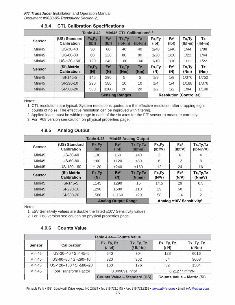
F/T Transducer Installation and Operation ManualDocument #9620-05-Transducer Section-21
Pinnacle Park • 1031 Goodworth Drive • Apex, NC 27539 • Tel: 919.772.0115 • Fax: 919.772.8259 • www.ati-ia.com • Email: [email protected] 75
4.9.4 CTLCalibrationSpecificationsTable 4.42— Mini45 CTL Calibrations1, 2
Sensor (US)Standard Calibration
Fx,Fy (lbf)
Fz3 (lbf)
Tx,Ty (lbf-in)
Tz (lbf-in)
Fx,Fy (lbf)
Fz3 (lbf)
Tx,Ty (lbf-in)
Tz (lbf-in)
Mini45 US-30-40 30 60 40 40 1/40 1/40 1/44 1/88Mini45 US-60-80 60 120 80 80 1/20 1/20 1/22 1/44Mini45 US-120-160 120 240 160 160 1/10 1/10 1/11 1/22
Sensor (SI)Metric Calibration
Fx,Fy (N)
Fz3 (N)
Tx,Ty (Nm)
Tz (Nm)
Fx,Fy (N)
Fz3 (N)
Tx,Ty (Nm)
Tz (Nm)
Mini45 SI-145-5 145 290 5 5 1/8 1/8 1/376 1/752Mini45 SI-290-10 290 580 10 10 1/4 1/4 1/188 1/376Mini45 SI-580-20 580 1160 20 20 1/2 1/2 1/94 1/188
Sensing Ranges Resolution(Controller)Notes: 1. CTL resolutions are typical. System resolutions quoted are the effective resolution after dropping eight countsofnoise.Theeffectiveresolutioncanbeimprovedwithfiltering. 2. Applied loads must be within range in each of the six axes for the F/T sensor to measure correctly. 3. For IP68 version see caution on physical properties page.
4.9.5 Analog Output
Table 4.43— Mini45 Analog Output
Sensor (US)Standard Calibration
Fx,Fy (lbf)
Fz2 (lbf)
Tx,Ty,Tz (lbf-in)
Fx,Fy (lbf/V)
Fz2 (lbf/V)
Tx,Ty,Tz (lbf-in/V)
Mini45 US-30-40 ±30 ±60 ±40 3 6 4Mini45 US-60-80 ±60 ±120 ±80 6 12 8Mini45 US-120-160 ±120 ±240 ±160 12 24 16
Sensor (SI)Metric Calibration
Fx,Fy (N)
Fz2 (N)
Tx,Ty,Tz (Nmm)
Fx,Fy (N/V)
Fz2 (N/V)
Tx,Ty,Tz (Nm/V)
Mini45 SI-145-5 ±145 ±290 ±5 14.5 29 0.5Mini45 SI-290-10 ±290 ±580 ±10 29 58 1Mini45 SI-580-20 ±580 ±1160 ±20 58 116 2
Analog Output Range Analog±10VSensitivity1
Notes: 1. ±5V Sensitivity values are double the listed ±10V Sensitivity values. 2. For IP68 version see caution on physical properties page.
4.9.6 CountsValue
Table 4.44—CountsValue
Sensor Calibration Fx,Fy,Fz (/lbf)
Tx,Ty,Tz (/lbf-in)
Fx,Fy,Fz (/N)
Tx,Ty,Tz (/Nm)
Mini45 US-30–40/SI-145–5 640 704 128 6016Mini45 US-60–80/SI-290–10 320 352 64 3008Mini45 US-120–160/SI-580–20 160 176 32 1504Mini45 Tool Transform Factor 0.009091 in/lbf 0.21277 mm/N
CountsValue–Standard(US) CountsValue–Metric(SI)

F/T Transducer Installation and Operation ManualDocument #9620-05-Transducer Section-21
Pinnacle Park • 1031 Goodworth Drive • Apex, NC 27539 • Tel: 919.772.0115 • Fax: 919.772.8259 • www.ati-ia.com • Email: [email protected] 76
4.9.7 Mini45(USCalibrationComplexLoading)(IncludesIP65/IP68)1
HelpMini45
US-30-40 US-60-80 US-120-160
Note: 1. For IP68 version see caution on physical properties page.

F/T Transducer Installation and Operation ManualDocument #9620-05-Transducer Section-21
Pinnacle Park • 1031 Goodworth Drive • Apex, NC 27539 • Tel: 919.772.0115 • Fax: 919.772.8259 • www.ati-ia.com • Email: [email protected] 77
4.9.8 Mini45(SICalibrationComplexLoading)(IncludesIP65/IP68)1
HelpMini45
SI-145-5 SI-290-10 SI-580-20
Note: 1. For IP68 version see caution on physical properties page.

F/T Transducer Installation and Operation ManualDocument #9620-05-Transducer Section-21
Pinnacle Park • 1031 Goodworth Drive • Apex, NC 27539 • Tel: 919.772.0115 • Fax: 919.772.8259 • www.ati-ia.com • Email: [email protected] 78
4.9.9 Mini45-E Transducer Drawing
3rd
AN
GLE
PRO
JEC
TION
21.1
46±0
.025
12.2
08±0
.025 9.57
69.
474
3.0
(See
Not
e 5)
20°
2X
3 Sl
ip F
it 3.
2C
usto
mer
Inte
rface
(See
Not
e 3)
14.
097±
0.02
5
10°
40°
B.C
.28
.2
6X T
ap M
3X0.
5 3.
0Pa
irs E
qual
ly S
pace
dC
usto
mer
Inte
rface
(See
Not
e 3)
Sens
ing
Ref
eren
ceFr
ame
Orig
in
+X
-X
-Y+Y
TOO
L SI
DE
12.1
45
3.5
15.7
-Z
Sens
ing
Ref
eren
ceFr
ame
Orig
in
Tool
Ada
pter
Mou
ntin
g Ad
apte
r
SID
E VI
EW
9.53
89.
512
3.0
(See
Not
e 5)
26.7
17.3
15.5
19.6
22±0
.025 10
°
10°3 Sl
ip F
it 5.
0C
usto
mer
Inte
rface
(See
Not
e 3)
5.
3
B.C
. 39
.24
+Z
6X T
ap M
3X0.
5 5.
0Pa
irs E
qual
ly S
pace
dC
usto
mer
Inte
rface
(See
Not
e 3)
+X -X
-Y+Y
MO
UN
TIN
G S
IDE
ISO
MET
RIC
VIE
W
NO
TES: Mat
eria
l: M
ount
ing
and
Tool
Ada
pter
mad
e of
Alu
min
um, T
rans
duce
r mad
e of
Sta
inle
ss S
teel
.1.
WA
RN
ING
: DO
NO
T LO
OSE
N O
R R
EMO
VE IN
TER
FAC
E PL
ATE
S O
R C
AB
LE D
UE
TO
2.PO
TEN
TIA
L D
AM
AG
E.D
O N
OT
EXC
EED
INTE
RFA
CE
DEP
TH. M
AY
CA
USE
DA
MA
GE.
3.St
anda
rd c
onne
ctor
(not
sho
wn)
has
17m
m d
iam
eter
& is
67.
5mm
long
.4.
Do
not a
llow
item
s pa
ssin
g th
roug
h ce
nter
hol
e to
touc
h bo
th th
e M
ount
ing
and
Tool
Ada
pter
5.
Plat
es o
r acc
urac
y w
ill be
com
prom
ised
.
Rev.
Des
crip
tion
Initi
ator
Dat
e
05
ECO
139
27; U
pdat
ed to
show
cor
rect
orie
ntat
ion
of To
ol A
dapt
er,
repo
sitio
ned
Tool
Sid
e di
men
sions
/cal
l out
s to
elim
inat
e ov
erla
ppin
g, a
nd u
pdat
ed Ti
tle B
lock
. Upd
ated
Not
es to
incl
ude
mor
e de
taile
d in
form
atio
n an
d to
mov
e C
usto
mer
Inte
rface
from
N
otes
to sp
ecifi
c as
sem
bly
feat
ures
.
SZJ
3/15
/201
6
B2:
11
1RE
VISIO
N
NO
TES:
UN
LESS
OTH
ERW
ISE
SPEC
IFIED
.
DO
NO
T SC
ALE
DRA
WIN
G.
ALL
DIM
ENSI
ON
S A
RE IN
M
ILLIM
ETER
S.
DRA
WN
BY:
CHE
CKE
D B
Y:
J. P
arke
r 1/1
0/07
P. F
usco
1/1
0/07
TITLE SC
ALE
SIZE
DRA
WIN
G N
UMBE
R
PRO
JEC
T #SH
EET
O
F 92
30-0
5-13
1505
PRO
PERT
Y O
F A
TI IN
DUS
TRIA
L A
UTO
MA
TION
, IN
C. N
OT T
O B
E RE
PRO
DUC
ED IN
AN
Y M
AN
NER
EXC
EPT O
N O
RDER
OR
WITH
PRI
OR
WRI
TTEN
AUT
HORI
ZATIO
N O
F A
TI.
1031
Goo
dwor
th Dr
ive, A
pex,
NC 27
539,
USA
Tel: +
1.919
.772.0
115
Em
ail: in
fo@ati
-ia.co
mFa
x: +1
.919.7
72.82
59
www
.ati-ia
.com
ISO
9001
Reg
ister
ed C
ompa
ny
Min
i45-
E Tr
ansd
ucer
with
Stra
in R
elie
ved
Cab
le

F/T Transducer Installation and Operation ManualDocument #9620-05-Transducer Section-21
Pinnacle Park • 1031 Goodworth Drive • Apex, NC 27539 • Tel: 919.772.0115 • Fax: 919.772.8259 • www.ati-ia.com • Email: [email protected] 79
4.9.10 Mini45-ERA Transducer Drawing
3rd
AN
GLE
PRO
JEC
TION
19.6
22±0
.025
50°
20°
39.2
4
15.8
31.3
30.95.
3
9.57
69.
474
3(S
ee N
ote
5)
13.5
6X T
ap M
3X0.
5 5
Pairs
Equ
ally
Spa
ced
Cus
tom
er In
terfa
ce
(See
Not
e 3)
3 (S
lip F
it)
5.0
Cus
tom
er In
terfa
ce(S
ee N
ote
3) MO
UN
TIN
G S
IDE
+X -X
-Y+Y
45
15.7
8.3
SID
E VI
EW
Tool
Ada
pter
Plat
eM
ount
ing
Adap
ter
Plat
e
Sens
ing
Ref
eren
ceFr
ame
Orig
in
+Z
14.0
97±0
.025
21.1
46±0
.025
12.2
08±0
.025
40°
40°
9.57
69.
474
3(S
ee N
ote
5)
6X T
ap M
3X0.
5 3
Pairs
Equ
ally
Spa
ced
Cus
tom
er In
terfa
ce(S
ee N
ote
3)2X
3
(Slip
Fit)
3
.2C
usto
mer
Inte
rface
(See
Not
e 3)
28
.2
TOO
L S
IDESe
nsin
g R
efer
ence
Fram
e O
rigin
-X
+X
+Y-Y
ISO
MET
RIC
VIE
W
NO
TES:
1. M
ater
ial:
Mou
ntin
g an
d To
ol a
dapt
er m
ade
of A
lum
inum
, Tra
nsdu
cer m
ade
o
f Sta
inle
ss S
teel
.2.
WA
RN
ING
: DO
NO
T LO
OSE
N O
R R
EMO
VE IN
TER
FAC
E PL
ATE
S O
R
CA
BLE
DU
E TO
PO
TEN
TIA
L D
AM
AG
E.3.
DO
NO
T EX
CEE
D IN
TER
FAC
E D
EPTH
. MA
Y C
AU
SE D
AM
AG
E.4.
Sta
ndar
d co
nnec
tor (
not s
how
n) h
as 1
7mm
dia
met
er &
is 6
7.5m
m lo
ng.
5. D
o no
t allo
w it
ems
pass
ing
thro
ugh
cent
er h
ole
to to
uch
both
the
mou
ntin
g
and
tool
ada
pter
pla
tes
or a
ccur
acy
will
be c
ompr
omis
ed.
-Z
Rev.
Des
crip
tion
Initi
ator
Dat
e
04EC
O 1
4343
: Add
ed m
issin
g 28
.2 c
all o
ut to
TOO
L SI
DE
view
; Upd
ated
not
es, f
orm
attin
g to
cur
rent
stan
dard
s.TB
C8/
1/20
16
B2:
11
1RE
VISIO
N
NO
TES:
UN
LESS
OTH
ERW
ISE
SPEC
IFIED
.
DO
NO
T SC
ALE
DRA
WIN
G.
ALL
DIM
ENSI
ON
S A
RE IN
M
ILLIM
ETER
S.
DRA
WN
BY:
CHE
CKE
D B
Y:
R. C
ham
bers
7/1
7/08
P. F
usco
7/1
7/08
TITLE SC
ALE
SIZE
DRA
WIN
G N
UMBE
R
PRO
JEC
T #SH
EET
O
F 92
30-0
5-13
3804
PRO
PERT
Y O
F A
TI IN
DUS
TRIA
L A
UTO
MA
TION
, IN
C. N
OT T
O B
E RE
PRO
DUC
ED IN
AN
Y M
AN
NER
EXC
EPT O
N O
RDER
OR
WITH
PRI
OR
WRI
TTEN
AUT
HORI
ZATIO
N O
F A
TI.
1031
Goo
dwor
th Dr
ive, A
pex,
NC 27
539,
USA
Tel: +
1.919
.772.0
115
Em
ail: in
fo@ati
-ia.co
mFa
x: +1
.919.7
72.82
59
www
.ati-ia
.com
ISO
9001
Reg
ister
ed C
ompa
ny
Min
i45-
ERA
Tran
sduc
er
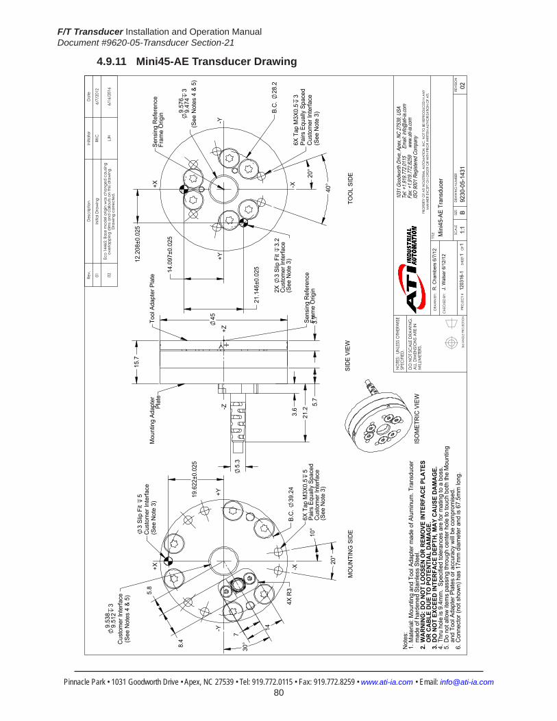
F/T Transducer Installation and Operation ManualDocument #9620-05-Transducer Section-21
Pinnacle Park • 1031 Goodworth Drive • Apex, NC 27539 • Tel: 919.772.0115 • Fax: 919.772.8259 • www.ati-ia.com • Email: [email protected] 80
4.9.11 Mini45-AE Transducer Drawing
3rd
AN
GLE
PRO
JEC
TION
14
4X
R3
20°
10°
5.8
8.4
19.
622±
0.02
5
B.C
. 39
.24
3 Sl
ip F
it 5
Cus
tom
er In
terfa
ce(S
ee N
ote
3)
9.53
89.
512
3C
usto
mer
Inte
rface
(See
Not
es 4
& 5
)
30°
7
-X
+Y-Y
+X
6X T
ap M
3X0.
55
Pairs
Equ
ally
Spa
ced
Cus
tom
er In
terfa
ce(S
ee N
ote
3)
45
5.7
15.
7
5.
3
3.6
21.
2 3
.7
+Z-Z
Tool
Ada
pter
Pla
te
Sens
ing
Ref
eren
ce
Fram
e O
rigin
Mou
ntin
g Ad
apte
r Pl
ate
12.
208±
0.02
5
14.
097±
0.02
5
21.
146±
0.02
5
20°
40°
9.57
69.
474
3(S
ee N
otes
4 &
5)
B.C
. 28
.2
6X T
ap M
3X0.
53
Pairs
Equ
ally
Spa
ced
Cus
tom
er In
terfa
ce(S
ee N
ote
3)
-X
-Y
+X
+Y
2X
3 Sl
ip F
it 3.
2C
usto
mer
Inte
rface
(See
Not
e 3)
Sens
ing
Ref
eren
ceFr
ame
Orig
in
SID
E VI
EW
ISO
MET
RIC
VIE
W
Not
es:
Mat
eria
l: M
ount
ing
and
Tool
Ada
pter
mad
e of
Alu
min
um. T
rans
duce
r 1.
mad
e of
har
dene
d St
ainl
ess
Stee
l.W
AR
NIN
G: D
O N
OT
LOO
SEN
OR
REM
OVE
INTE
RFA
CE
PLA
TES
2.O
R C
AB
LE D
UE
TO P
OTE
NTI
AL
DA
MA
GE.
DO
NO
T EX
CEE
D IN
TER
FAC
E D
EPTH
, MA
Y C
AU
SE D
AM
AG
E.3.
Thru
hol
e is
9.4
mm
. Sp
ecifi
ed to
lera
nces
are
for m
atin
g to
a b
oss.
4.D
o no
t allo
w it
ems
pass
ing
thro
ugh
cent
er h
ole
to to
uch
both
the
Mou
ntin
g5.
and
Tool
Ada
pter
Pla
tes
or a
ccur
acy
will
be c
ompr
omis
ed.
Con
nect
or (n
ot s
how
n) h
as 1
7mm
dia
met
er a
nd is
67.
5mm
long
.6.
MO
UN
TIN
G S
IDE
TOO
L SI
DE
Rev.
Des
crip
tion
Initi
ator
Dat
e
01In
itial
Dra
win
gRK
C6/
7/20
12
02Ec
o 14
465;
Bas
e m
odel
orig
in w
as c
hang
ed c
ausin
g ov
erla
ppin
g di
ms a
nd c
allo
uts o
n th
is dr
awin
g.
Dra
win
g co
rrect
ed.
LJH
6/16
/201
6
B1:
11
1RE
VISIO
N
NO
TES:
UN
LESS
OTH
ERW
ISE
SPEC
IFIED
.
DO
NO
T SC
ALE
DRA
WIN
G.
ALL
DIM
ENSI
ON
S A
RE IN
M
ILLIM
ETER
S.
DRA
WN
BY:
CHE
CKE
D B
Y:
R. C
ham
bers
6/7
/12
J. W
alse
r 6/1
2/12
TITLE SC
ALE
SIZE
DRA
WIN
G N
UMBE
R
PRO
JEC
T #SH
EET
O
F 92
30-0
5-14
3112
0316
-102
PRO
PERT
Y O
F A
TI IN
DUS
TRIA
L A
UTO
MA
TION
, IN
C. N
OT T
O B
E RE
PRO
DUC
ED IN
AN
Y M
AN
NER
EXC
EPT O
N O
RDER
OR
WITH
PRI
OR
WRI
TTEN
AUT
HORI
ZATIO
N O
F A
TI.
1031
Goo
dwor
th Dr
ive, A
pex,
NC 27
539,
USA
Tel: +
1.919
.772.0
115
Em
ail: in
fo@ati
-ia.co
mFa
x: +1
.919.7
72.82
59
www
.ati-ia
.com
ISO
9001
Reg
ister
ed C
ompa
ny
Min
i45-
AE T
rans
duce
r

F/T Transducer Installation and Operation ManualDocument #9620-05-Transducer Section-21
Pinnacle Park • 1031 Goodworth Drive • Apex, NC 27539 • Tel: 919.772.0115 • Fax: 919.772.8259 • www.ati-ia.com • Email: [email protected] 81
4.9.12 Mini45IP65/IP68TransducerDrawing
3rd
AN
GLE
PRO
JEC
TION
19.
622±
0.02
5
9.53
89.
512
3C
usto
mer
Inte
rface
3 Sl
ip F
it 4
.5C
usto
mer
Inte
rface
B.C
. 39
.2
38.6
MAX
7.
4
6X T
ap M
3X0.
5 4
.5Pa
irs E
qual
ly S
pace
dC
usto
mer
Inte
rface
10°
10°
B.C
. 25
.4
120
°
22.
5°
+Y
-X
-Y
+X
MO
UN
TIN
G S
IDE
Min
i45-
A C
able
Exi
t(A
ltern
ate)
25.
1
57
.9
10.4
MAX
Sens
ing
Ref
eren
ceFr
ame
Orig
in
Mou
ntin
g Ad
apte
rPl
ate
Tool
ing
Adap
ter
Plat
e
+Z-Z
SID
E VI
EW
Min
i45-
A C
able
Exi
t(A
ltern
ate)
2X
3 Sl
ip F
it 4
.5C
usto
mer
Inte
rface
B.C
. 28
.2
14.
097±
0.02
5
20°
2
0°
21.
146±
0.02
5
12.
207±
0.02
5
6X T
ap M
3X0.
5 4
.5Pa
irs E
qual
ly S
pace
dC
usto
mer
Inte
rface
Sens
ing
Ref
eren
ceFr
ame
Orig
in
-Y
+X
+Y
-X
TOO
L SI
DE
MIN
I45-
R IS
OM
ETR
IC V
IEW
ALTE
RN
ATE
CAB
LE E
XIT
MIN
I45-
A
Not
es:
Mat
eria
l: St
ainl
ess
Stee
l1.
Tool
and
Mou
ntin
g Ad
apte
rs h
ave
M3
tapp
ed h
oles
and
3m
m d
owel
pin
hol
es fo
r 2.
inte
rfaci
ng.
WA
RN
ING
: DO
NO
T LO
OSE
N O
R R
EMO
VE IN
TER
FAC
E PL
ATE
S D
UE
TO
3.PO
TEN
TIA
L D
AM
AG
E.St
anda
rd c
onne
ctor
(not
sho
wn)
has
17m
m d
iam
eter
& is
67.
5mm
long
.4.
Cab
le is
IP65
rate
d on
ly a
t tra
nsdu
cer e
nd.
5.
Rev.
Des
crip
tion
Initi
ator
Dat
e
03EC
O 1
1152
: Add
axia
l cab
le e
xit lo
catio
nLT
F6/
27/2
013
B1:
11
1RE
VISIO
N
NO
TES:
UN
LESS
OTH
ERW
ISE
SPEC
IFIED
.
DO
NO
T SC
ALE
DRA
WIN
G.
ALL
DIM
ENSI
ON
S A
RE IN
M
ILLIM
ETER
S.
DRA
WN
BY:
CHE
CKE
D B
Y:
L. F
ishe
r, 2/
18/1
3
J. W
alse
r, 2/
20/1
3
TITLE SC
ALE
SIZE
DRA
WIN
G N
UMBE
R
PRO
JEC
T #SH
EET
O
F 92
30-0
5-14
4313
0130
-103
PRO
PERT
Y O
F A
TI IN
DUS
TRIA
L A
UTO
MA
TION
, IN
C. N
OT T
O B
E RE
PRO
DUC
ED IN
AN
Y M
AN
NER
EXC
EPT O
N O
RDER
OR
WITH
PRI
OR
WRI
TTEN
AUT
HORI
ZATIO
N O
F A
TI.
1031
Goo
dwor
th Dr
ive, A
pex,
NC 27
539,
USA
Tel: +
1.919
.772.0
115
Em
ail: in
fo@ati
-ia.co
mFa
x: +1
.919.7
72.82
59
www
.ati-ia
.com
ISO
9001
Reg
ister
ed C
ompa
ny
IP65
/IP68
Min
i45
Tran
sduc
er

F/T Transducer Installation and Operation ManualDocument #9620-05-Transducer Section-21
Pinnacle Park • 1031 Goodworth Drive • Apex, NC 27539 • Tel: 919.772.0115 • Fax: 919.772.8259 • www.ati-ia.com • Email: [email protected] 82
4.9.13 Legacy Mini45 Transducer Drawing
3rd
AN
GLE
PRO
JEC
TION
9.57
69.
474
3
(See
Not
es 4
& 5
)
21.1
46±0
.02512
.208
±0.0
252X
3
Slip
Fit3.
4C
usto
mer
Inte
rface
(See
Not
e 3)
40°
Typ.
14.0
97±0
.025
20°
20°
B.C
. 28
.2
6X Ta
p M
3x0.
5 3.
0Pa
irs E
qual
ly S
pace
dC
usto
mer
Inte
rface
(See
Not
e 3)
Min
i45-
R C
able
Exit
(Sta
ndar
d)
TOO
L SI
DE
+X
-Y+Y
-X
Sens
ing
Refe
renc
eFr
ame
Orig
in
45
15.7
5.7
3.7To
ol A
dapt
er
Plat
e
Mou
ntin
g A
dapt
er P
late
+Z-Z
SID
E VI
EW
Sens
ing
Refe
renc
eFr
ame
Orig
in
9.53
89.
512
3
Cus
tom
er In
terfa
ce(S
ee N
otes
4 &
5)
19.6
22±0
.025
3 Sli
p Fit
5C
usto
mer
Inte
rface
(See
Not
e 3)
5.2
2
10°
(120
°)
20°
Typ.
B.C
. 39
.24
B.C
. 25
.4
6X Ta
p M
3x0.
55.
0Pa
irs E
qual
ly S
pace
dC
usto
mer
Inte
rface
(See
Not
e 3)
MO
UNTIN
G S
IDE
-X
-Y+Y
+X
Not
es: M
ount
ing
and
Tool
Ada
pter
mad
e of
eith
er A
lum
inum
or S
tain
less
Ste
el1.
(cus
tom
er sp
ecifie
d).
Tran
sduc
er m
ade
of h
arde
ned
Stai
nles
s Ste
el.
WAR
NING
: DO
NO
T LO
OSE
N O
R RE
MO
VE IN
TERF
ACE
PLAT
ES
2.O
R C
ABLE
FITT
ING
DUE
TO P
OTE
NTIA
L DAM
AGE.
DO N
OT E
XCEE
D IN
TERF
ACE
DEPT
H, M
AY C
AUSE
DAM
AGE.
3.Th
ru h
ole
is 9.
4mm
. Sp
ecifie
d to
lera
nces
are
for m
atin
g to
a b
oss.
4.D
o no
t allo
w it
ems p
assin
g th
roug
h ce
nter
hol
e to
touc
h bo
th th
e M
ount
ing
5.an
d To
ol A
dapt
er P
late
s or a
ccur
acy
will
be c
ompr
omise
d.C
onne
ctor
(not
show
n) h
as 1
7mm
dia
met
er a
nd is
67.
5mm
long
.6.
Min
i45-
A C
able
Exit
(Alte
rnat
e)
MIN
I45-
R IS
OM
ETRI
C V
IEW
ALT
ERN
ATE
CA
BLE
EXIT
MIN
I45-
A
ALT
ERN
ATE
CA
BLE
EXIT
MIN
I45-
EA
LTER
NA
TE C
ABL
E EX
ITM
INI4
5-ER
AA
LTER
NA
TE C
ABL
E EX
ITM
INI4
5-A
E
Min
i45-
R C
able
Exit
(Sta
ndar
d)
Rev.
Des
crip
tion
Initi
ator
Dat
e
20EC
O 1
0071
; Add
alte
rnat
e ca
ble
exit
view
s for
Min
i45-
AE
& M
ini4
5-ER
AM
SD9/
6/20
12
B2:
11
1RE
VISIO
N
NO
TES:
UN
LESS
OTH
ERW
ISE
SPEC
IFIED
.
DO
NO
T SC
ALE
DRA
WIN
G.
ALL
DIM
ENSI
ON
S A
RE IN
M
ILLIM
ETER
S.
DRA
WN
BY:
CHE
CKE
D B
Y:
B. D
iges
o
D.N
orto
n 2/
26/0
6
TITLE SC
ALE
SIZE
DRA
WIN
G N
UMBE
R
PRO
JEC
T #SH
EET
O
F 92
30-0
5-10
9420
PRO
PERT
Y O
F A
TI IN
DUS
TRIA
L A
UTO
MA
TION
, IN
C. N
OT T
O B
E RE
PRO
DUC
ED IN
AN
Y M
AN
NER
EXC
EPT O
N O
RDER
OR
WITH
PRI
OR
WRI
TTEN
AUT
HORI
ZATIO
N O
F A
TI.
1031
Goo
dwor
th Dr
ive, A
pex,
NC 27
539,
USA
Tel: +
1.919
.772.0
115
Em
ail: in
fo@ati
-ia.co
mFa
x: +1
.919.7
72.82
59
www
.ati-ia
.com
ISO
9001
Reg
ister
ed C
ompa
ny
Min
i45
Tran
sduc
er

F/T Transducer Installation and Operation ManualDocument #9620-05-Transducer Section-21
Pinnacle Park • 1031 Goodworth Drive • Apex, NC 27539 • Tel: 919.772.0115 • Fax: 919.772.8259 • www.ati-ia.com • Email: [email protected] 83
4.10 Mini58Specifications(IncludesIP60/IP65/IP68Versions)4.10.1 Mini58PhysicalProperties
Table 4.45—Mini58PhysicalPropertiesSingle-Axis Overload (US)StandardUnits (SI)MetricUnitsFxy ±4800 lbf ±21000 NFz ±11000 lbf ±48000 NTxy ±5300 inf-lb ±590 NmTz ±7100 inf-lb ±800 NmStiffness(Calculated) X-axis&Y-axisforces(Kx,Ky) 1.4x10⁶ lb/in 2.5x10⁸ N/m Z-axisforce(Kz) 2.1x10⁶ lb/in 3.7x10⁸ N/m X-axis&Y-axistorque(Ktx,Kty) 9.3x10⁵ lbf-in/rad 1.1x10⁵ Nm/rad Z-axistorque(Ktz) 1.8x10⁶ lbf-in/rad 2.0x10⁵ Nm/rad Resonant Frequency Fx, Fy, Tz 3000 Hz 3000 HzFz, Tx, Ty 5700 Hz 5700 HzPhysicalSpecifications Weight1 0.76 lb 0.345 kgDiameter1 2.28 in 58 mmHeight1 1.18 in 30 mmNote: 1.Specificationsincludestandardinterfaceplates.
4.10.2 Mini58IP60PhysicalPropertiesTable 4.46—Mini58IP60PhysicalProperties
Single-Axis Overload (US)StandardUnits (SI)MetricUnitsFxy ±4800 lbf ±21000 NFz ±11000 lbf ±48000 NTxy ±5300 inf-lb ±590 NmTz ±7100 inf-lb ±800 NmStiffness(Calculated) X-axis&Y-axisforces(Kx,Ky) 1.4x10⁶ lb/in 2.5x10⁸ N/m Z-axisforce(Kz) 2.1x10⁶ lb/in 3.7x10⁸ N/m X-axis&Y-axistorque(Ktx,Kty) 9.3x10⁵ lbf-in/rad 1.1x10⁵ Nm/rad Z-axistorque(Ktz) 1.8x10⁶ lbf-in/rad 2.0x10⁵ Nm/rad Resonant Frequency Fx, Fy, Tz N/A N/AFz, Tx, Ty N/A N/APhysicalSpecifications Weight1 1.15 lb 0.522 kgDiameter1 3.23 in 82 mmHeight1 1.42 in 36.2 mmNote: 1.Specificationsincludestandardinterfaceplates.

F/T Transducer Installation and Operation ManualDocument #9620-05-Transducer Section-21
Pinnacle Park • 1031 Goodworth Drive • Apex, NC 27539 • Tel: 919.772.0115 • Fax: 919.772.8259 • www.ati-ia.com • Email: [email protected] 84
4.10.3 Mini58IP65/IP68PhysicalPropertiesTable 4.47—Mini58IP65/IP68PhysicalProperties
Single-Axis Overload (US)StandardUnits (SI)MetricUnitsFxy ±4800 lbf ±21000 NFz ±11000 lbf ±48000 NTxy ±5300 inf-lb ±590 NmTz ±7100 inf-lb ±800 NmStiffness(Calculated) X-axis&Y-axisforces(Kx,Ky) 1.4x10⁶ lb/in 2.5x10⁸ N/m Z-axisforce(Kz) 2.1x10⁶ lb/in 3.7x10⁸ N/m X-axis&Y-axistorque(Ktx,Kty) 9.3x10⁵ lbf-in/rad 1.1x10⁵ Nm/rad Z-axistorque(Ktz) 1.8x10⁶ lbf-in/rad 2.0x10⁵ Nm/rad Resonant Frequency Fx, Fy, Tz N/A N/AFz, Tx, Ty N/A N/APhysicalSpecifications Weight1 1.77 lb 0.804 kgDiameter1 2.58 in 65.4 mmHeight1 1.48 in 37.6 mmNote: 1.Specificationsincludestandardinterfaceplates.
CAUTION: When submerged, IP68 transducers exhibit a decrease in Fz range related to the submersion depth. This loss is the result of pressure-induced preloading on the transducer. The preload can be masked by biasing the transducer at the depth prior to applying the load to be measured. The following estimates are for room temperature fresh water at sea level.
Submersion DepthIP68Mini58 US MetricFz preload at 4 m depth 24.3 lb 108 NFz preload at other depths -1.86 lb/ft × depthInFeet -27.1 N/m × depthInMeters

F/T Transducer Installation and Operation ManualDocument #9620-05-Transducer Section-21
Pinnacle Park • 1031 Goodworth Drive • Apex, NC 27539 • Tel: 919.772.0115 • Fax: 919.772.8259 • www.ati-ia.com • Email: [email protected] 85
4.10.4 CalibrationSpecifications(excludesCTLcalibrations)
Table4.48—Mini58Calibrations(excludesCTLcalibrations)1, 2
Sensor (US)Standard Calibration
Fx,Fy (lbf)
Fz3 (lbf)
Tx,Ty (lbf-in)
Tz (lbf-in)
Fx,Fy (lbf)
Fz3 (lbf)
Tx,Ty (lbf-in)
Tz (lbf-in)
Mini58 US-150-250 150 375 250 250 5/112 1/16 1/20 7/240Mini58 US-300-500 300 750 500 500 5/56 1/8 1/10 7/120Mini58 US-600-1000 600 1500 1000 1000 5/28 1/4 1/5 7/60
Sensor (SI)Metric Calibration
Fx,Fy (N)
Fz3 (N)
Tx,Ty (Nm)
Tz (Nm)
Fx,Fy (N)
Fz3 (N)
Tx,Ty (Nm)
Tz (Nm)
Mini58 SI-700-30 700 1700 30 30 1/6 7/24 9/1600 1/320Mini58 SI-1400-60 1400 3400 60 60 1/3 7/12 9/800 1/160Mini58 SI-2800-120 2800 6800 120 120 3/4 1 1/4 9/400 1/80
Sensing Ranges Resolution(DAQ,NetF/T)4
Notes: 1. These system resolutions quoted are the effective resolution after dropping four counts of noise. Theeffectiveresolutioncanbeimprovedwithfiltering. 2. Applied loads must be within range in each of the six axes for the F/T sensor to measure correctly. 3. For IP68 version see caution on physical properties page. 4. DAQ resolutions are typical for a 16-bit data acquisition system.
4.10.5 CTLCalibrationSpecifications
Table 4.49—Mini58CTLCalibrations1, 2
Sensor (US)Standard Calibration
Fx,Fy (lbf)
Fz3 (lbf)
Tx,Ty (lbf-in)
Tz (lbf-in)
Fx,Fy (lbf)
Fz3 (lbf)
Tx,Ty (lbf-in)
Tz (lbf-in)
Mini58 US-150-250 150 375 250 250 5/56 1/8 1/10 7/120Mini58 US-300-500 300 750 500 500 5/28 1/4 1/5 7/60Mini58 US-600-1000 600 1500 1000 1000 5/14 1/2 2/5 7/30
Sensor (SI)Metric Calibration
Fx,Fy (N)
Fz3 (N)
Tx,Ty (Nm)
Tz (Nm)
Fx,Fy (N)
Fz3 (N)
Tx,Ty (Nm)
Tz (Nm)
Mini58 SI-700-30 700 1700 30 30 1/3 7/12 9/800 1/160Mini58 SI-1400-60 1400 3400 60 60 2/3 1 1/6 9/400 1/80Mini58 SI-2800-120 2800 6800 120 120 1 1/2 2 1/2 9/200 1/40
Sensing Ranges Resolution(Controller)Notes: 1. CTL resolutions are typical. System resolutions quoted are the effective resolution after dropping eight countsofnoise.Theeffectiveresolutioncanbeimprovedwithfiltering. 2. Applied loads must be within range in each of the six axes for the F/T sensor to measure correctly. 3. For IP68 version see caution on physical properties page.

F/T Transducer Installation and Operation ManualDocument #9620-05-Transducer Section-21
Pinnacle Park • 1031 Goodworth Drive • Apex, NC 27539 • Tel: 919.772.0115 • Fax: 919.772.8259 • www.ati-ia.com • Email: [email protected] 86
4.10.6 Analog Output
Table 4.50—Mini58AnalogOutput
Sensor (US)Standard Calibration
Fx,Fy (lbf)
Fz2 (lbf)
Tx,Ty,Tz (lbf-in)
Fx,Fy (lbf/V)
Fz2 (lbf/V)
Tx,Ty,Tz (lbf-in/V)
Mini58 US-150-250 ±150 ±375 ±250 15 37.5 25Mini58 US-300-500 ±300 ±750 ±500 30 75 50Mini58 US-600-1000 ±600 ±1500 ±1000 60 150 100
Sensor (SI)Metric Calibration
Fx,Fy (N)
Fz2 (N)
Tx,Ty,Tz (Nmm)
Fx,Fy (N/V)
Fz2 (N/V)
Tx,Ty,Tz (Nm/V)
Mini58 SI-700-30 ±700 ±1700 ±30 70 170 3Mini58 SI-1400-60 ±1400 ±3400 ±60 140 340 6Mini58 SI-2800-120 ±2800 ±6800 ±120 280 680 12
Analog Output Range Analog±10VSensitivity1
Notes: 1. ±5V Sensitivity values are double the listed ±10V Sensitivity values. 2. For IP68 version see caution on physical properties page.
4.10.7 CountsValueTable 4.51—CountsValue
Sensor Calibration Fx,Fy,Fz (/lbf)
Tx,Ty,Tz (/lbf-in)
Fx,Fy,Fz (/N)
Tx,Ty,Tz (/Nm)
Mini58 US-150-250/SI-700-30 448 960 96 6400Mini58 US-300-500/SI-1400-60 224 480 48 3200Mini58 US-600-1000/SI-2800-120 112 240 16 1600Mini58 Tool Transform Factor See Tool Transform Factor table
CountsValue–Standard(US) CountsValue–Metric(SI)
4.10.8 Tool Transform Factor
Table 4.52—Tool Transform FactorSensor Calibration US(English) SI(Metric)Mini58 US-150-250/SI-700-30 0.00467 in/lbf 0.150 mm/NMini58 US-300-500/SI-1400-60 0.00467 in/lbf 0.150 mm/NMini58 US-600-1000/SI-2800-120 0.00467 in/lbf 0.150 mm/N
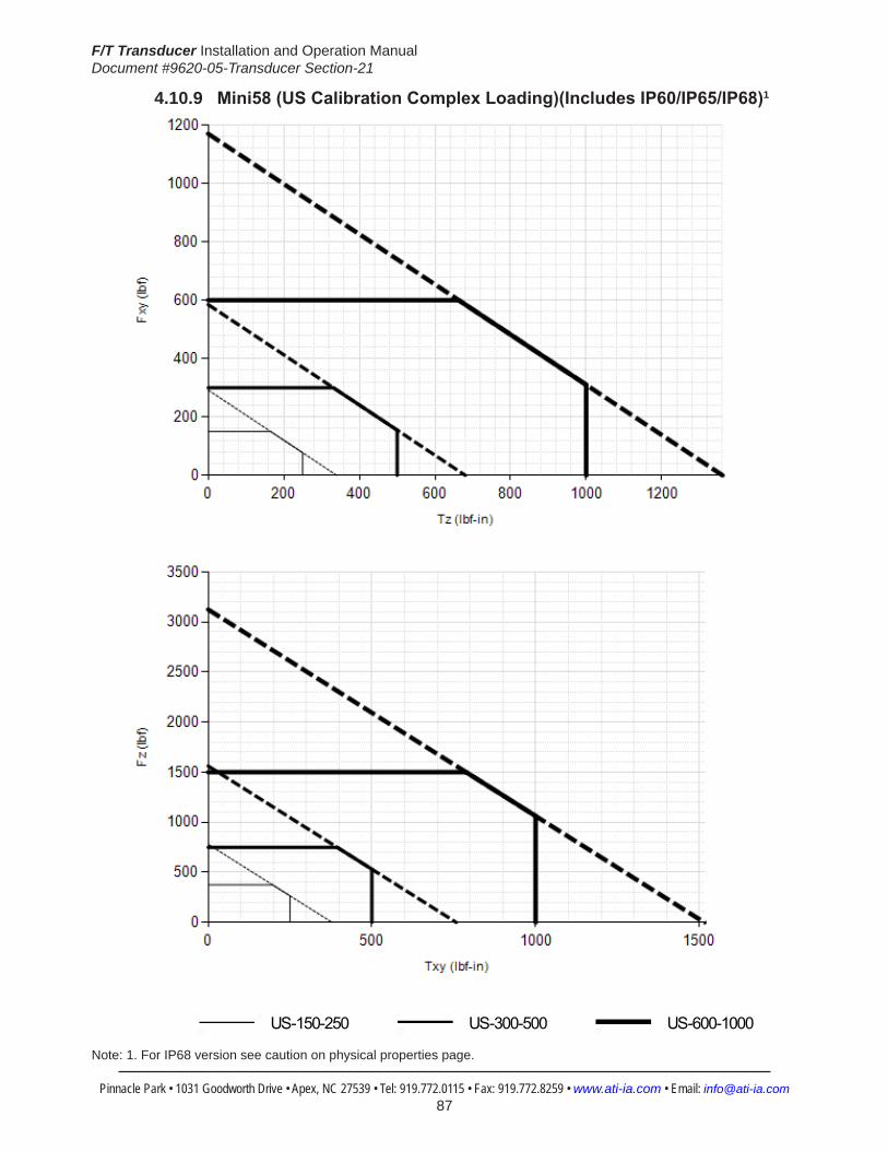
F/T Transducer Installation and Operation ManualDocument #9620-05-Transducer Section-21
Pinnacle Park • 1031 Goodworth Drive • Apex, NC 27539 • Tel: 919.772.0115 • Fax: 919.772.8259 • www.ati-ia.com • Email: [email protected] 87
4.10.9 Mini58(USCalibrationComplexLoading)(IncludesIP60/IP65/IP68)1
HelpMini58
US-150-250 US-300-500 US-600-1000
Note: 1. For IP68 version see caution on physical properties page.
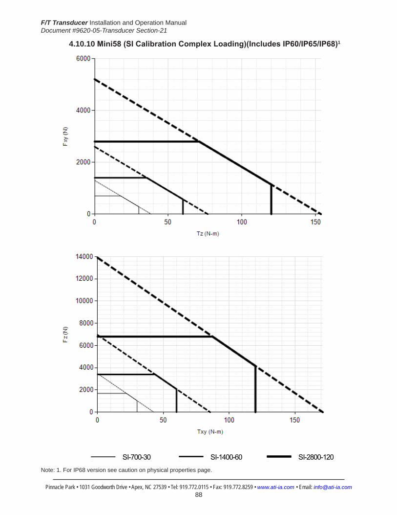
F/T Transducer Installation and Operation ManualDocument #9620-05-Transducer Section-21
Pinnacle Park • 1031 Goodworth Drive • Apex, NC 27539 • Tel: 919.772.0115 • Fax: 919.772.8259 • www.ati-ia.com • Email: [email protected] 88
4.10.10 Mini58(SICalibrationComplexLoading)(IncludesIP60/IP65/IP68)1
HelpMini58
SI-700-30 SI-1400-60 SI-2800-120
Note: 1. For IP68 version see caution on physical properties page.

F/T Transducer Installation and Operation ManualDocument #9620-05-Transducer Section-21
Pinnacle Park • 1031 Goodworth Drive • Apex, NC 27539 • Tel: 919.772.0115 • Fax: 919.772.8259 • www.ati-ia.com • Email: [email protected] 89
4.10.11 Mini58TransducerDrawing
3rd
AN
GLE
PRO
JEC
TION
18°
36°
Typ
(See
Not
e 3)
Cus
tom
er In
terfa
cePa
irs E
qual
ly S
pace
d6X
Tap
M5X
0.8
6.5
23±0
.025
34.5
±0.0
25
19.9
±0.0
25
6.1 8.
4
14
B.C
.39
Cus
tom
er In
terfa
ce2X
4.
059
4.03
4 S
lip F
it 3.
7
9.5
Thru
(See
Not
e 5)
4.2
30°
7
MO
UN
TIN
G S
IDE
+X -X
-Y+Y
Min
i58-
E C
able
Exi
t(A
ltern
ate)
58
30
3.6
5.3
17.3
R2
SID
E VI
EW
Sens
ing
Ref
eren
ce
Fram
e O
rigin
Mou
ntin
gAd
apte
r Pl
ate
Tool
Ada
pter
Pla
te
-Z+Z
19.6
85±0
.025
29.5
28±0
.025
17.0
48±0
.025
18°
36°
(See
Not
e 3)
Cus
tom
er In
terfa
cePa
irs E
qual
ly S
pace
d6X
Tap
M5X
0.8
6.5
Cus
tom
er In
terfa
ce2X
4
Slip
Fit
3.7
B.C
.39
TOO
L SI
DE
+X -X
-Y+Y
Sens
ing
Ref
eren
ce
Fram
e O
rigin
ISO
MET
RIC
VIE
WAL
TER
NAT
E C
ABLE
EXI
TM
INI5
8-E
ALTE
RN
ATE
CAB
LE E
XIT
MIN
I58-
ERA
Not
es: M
ater
ial:
Hard
ened
Sta
inle
ss S
teel
and
Alu
min
um.
1.W
ARN
ING
: DO
NO
T LO
OSE
N O
R RE
MO
VE IN
TERF
AC
E PL
ATE
S 2.
OR
CA
BLE
DUE
TO P
OTE
NTIA
L DA
MA
GE.
DO N
OT E
XCEE
D IN
TERF
AC
E DE
PTH.
MA
Y C
AUS
E DA
MA
GE.
3.St
anda
rd c
onne
ctor
(not
show
n) h
as 1
7mm
dia
met
er a
nd is
67.
5mm
long
.4. 5.
Do
not a
llow
item
s pas
sing
thro
ugh
cent
er h
ole
to to
uch
both
the
Mou
ntin
g an
d To
ol A
dapt
er P
late
s or a
ccur
acy
will
be c
ompr
omise
d.
Rev.
Des
crip
tion
Initi
ator
Dat
e
05Ec
o 11
916:
Upd
ate
mat
eria
l not
e.LC
S3/
17/2
014
06EC
O 1
6103
: Add
ed IS
O v
iew
RTD
1/9/
2018
B3:
21
1RE
VISIO
N
NO
TES:
UN
LESS
OTH
ERW
ISE
SPEC
IFIED
.
DO
NO
T SC
ALE
DRA
WIN
G.
ALL
DIM
ENSI
ON
S A
RE IN
M
ILLIM
ETER
S.
DRA
WN
BY:
CHE
CKE
D B
Y:
R. C
ham
bers
2/4
/11
P. F
usco
2/7
/11
TITLE SC
ALE
SIZE
DRA
WIN
G N
UMBE
R
PRO
JEC
T #SH
EET
O
F 92
30-0
5-13
8310
1119
-106
PRO
PERT
Y O
F A
TI IN
DUS
TRIA
L A
UTO
MA
TION
, IN
C. N
OT T
O B
E RE
PRO
DUC
ED IN
AN
Y M
AN
NER
EXC
EPT O
N O
RDER
OR
WITH
PRI
OR
WRI
TTEN
AUT
HORI
ZATIO
N O
F A
TI.
1031
Goo
dwor
th Dr
ive, A
pex,
NC 27
539,
USA
Tel: +
1.919
.772.0
115
Em
ail: in
fo@ati
-ia.co
mFa
x: +1
.919.7
72.82
59
www
.ati-ia
.com
ISO
9001
Reg
ister
ed C
ompa
ny
Min
i58
Tran
sduc
er

F/T Transducer Installation and Operation ManualDocument #9620-05-Transducer Section-21
Pinnacle Park • 1031 Goodworth Drive • Apex, NC 27539 • Tel: 919.772.0115 • Fax: 919.772.8259 • www.ati-ia.com • Email: [email protected] 90
4.10.12 Mini58IP60TransducerDrawing
3rd
AN
GLE
PRO
JEC
TION
82
17.
048±
0.02
5
29.
528±
0.02
5 1
9.68
5±0.
025
18°
36°
Typ
.
6X T
ap M
5X0.
8 6
.5Pa
irs E
qual
ly S
pace
dC
usto
mer
Inte
rface
B.C
.39
2X4
Slip
Fit
6.0
Cus
tom
er In
terfa
ce
TOO
L SI
DE
+X -X
-Y+Y
Sens
ing
Ref
eren
ceFr
ame
Orig
in
58
36.
2 6
.4
4.8
SID
E VI
EW
-Z+Z
Tool
Adap
ter
Plat
e
Mou
ntin
gAd
apte
rPl
ate
IP60
Dus
t Wra
p
Sens
ing
Ref
eren
ceFr
ame
Orig
in
19.
919±
0.02
5
31.
826±
0.02
5
23±
0.02
5
36.
750±
0.02
5
18°
36°
Typ
.
6X T
ap M
5X0.
8 6
.5Pa
irs E
qual
ly S
pace
dC
usto
mer
Inte
rface
B.C
.39
34.
500±
0.02
5 5
5.12
5±0.
025
6X
5.5
Thr
uEq
ually
Spa
ced
For M
5 SH
CS
Cus
tom
er In
terfa
ceO
ptio
nal M
ount
ing
Side
Pat
tern
B.C
.73
.5
4X4
Slip
Fit
6.0
Cus
tom
er In
terfa
ce
30°
MO
UN
TIN
G S
IDE
+X -X
-Y+Y
ISO
MET
RIC
VIE
WN
otes
: Mat
eria
l: M
ount
ing
and
Tool
Ada
pter
mad
e of
Alu
min
um,
1.Tr
ansd
ucer
mad
e of
har
dene
d St
ainl
ess S
teel
.W
ARN
ING
: DO
NO
T LO
OSE
N O
R RE
MO
VE IN
TERF
AC
E PL
ATE
S 2.
OR
CA
BLE
FITT
ING
DUE
TO P
OTE
NTIA
L DA
MA
GE.
Stan
dard
con
nect
or (n
ot sh
own)
has
17m
m d
iam
eter
and
3.
is 67
.5m
m lo
ng.
Rev.
Des
crip
tion
Initi
ator
Dat
e
03M
odify
Mou
ntin
g Sid
e ta
p de
pth
to b
e 6.
5mm
JW12
/13/
2012
B1:
11
1RE
VISIO
N
NO
TES:
UN
LESS
OTH
ERW
ISE
SPEC
IFIED
.
DO
NO
T SC
ALE
DRA
WIN
G.
ALL
DIM
ENSI
ON
S A
RE IN
M
ILLIM
ETER
S.
DRA
WN
BY:
CHE
CKE
D B
Y:
J. W
alse
r 10/
15/2
012
P. F
usco
10/
15/2
012
TITLE SC
ALE
SIZE
DRA
WIN
G N
UMBE
R
PRO
JEC
T #SH
EET
O
F 92
30-0
5-14
3712
1009
-103
PRO
PERT
Y O
F A
TI IN
DUS
TRIA
L A
UTO
MA
TION
, IN
C. N
OT T
O B
E RE
PRO
DUC
ED IN
AN
Y M
AN
NER
EXC
EPT O
N O
RDER
OR
WITH
PRI
OR
WRI
TTEN
AUT
HORI
ZATIO
N O
F A
TI.
1031
Goo
dwor
th Dr
ive, A
pex,
NC 27
539,
USA
Tel: +
1.919
.772.0
115
Em
ail: in
fo@ati
-ia.co
mFa
x: +1
.919.7
72.82
59
www
.ati-ia
.com
ISO
9001
Reg
ister
ed C
ompa
ny
Rad
ial E
xit M
ini5
8 Tr
ansd
ucer
, IP6
0

F/T Transducer Installation and Operation ManualDocument #9620-05-Transducer Section-21
Pinnacle Park • 1031 Goodworth Drive • Apex, NC 27539 • Tel: 919.772.0115 • Fax: 919.772.8259 • www.ati-ia.com • Email: [email protected] 91
4.10.13 Mini58IP65/IP68TransducerDrawing
3rd
AN
GLE
PRO
JEC
TION
19.
944±
0.02
5
B.C
. 39
34.
500±
0.02
5
23.
022±
0.02
5
36°
2X S
lip F
it 4.
059
4.03
4 6
Cus
tom
er In
terfa
ce
9
6X T
ap M
5X0.
8 6
.5Pa
irs E
qual
ly S
pace
dC
usto
mer
Inte
rface
9
+X
+Y
-X
-Y
MO
UN
TIN
G S
IDE
R1
37.
6
1.3
65
.4
Mou
ntin
g Ad
apte
rPl
ate
+Z-Z
Sens
ing
Fram
e R
efer
ence
Orig
in
Tool
Ada
pter
Pla
te
SID
E VI
EW
29.
528±
0.02
5
2X S
lip F
it 4.
059
4.03
4 6
Cus
tom
er In
terfa
ce
19.
685±
0.02
5
B.C
. 39
36°
1
8°
6X T
ap M
5X0.
8 6
.7Pa
irs E
qual
ly S
pace
dC
usto
mer
Inte
rface
17.
048±
0.02
5
TOO
L SI
DE
Sens
ing
Ref
eren
ceFr
ame
Orig
in
+X -X
-Y+Y
ALTE
RN
ATE
CAB
LE E
XIT
MIN
I58-
E IP
65N
otes
:M
ater
ial:
Stai
nles
s St
eel
1.To
ol a
nd M
ount
ing
Adap
ters
hav
e M
5 ta
pped
hol
es a
nd 4
mm
dow
el p
in h
oles
for
2.in
terfa
cing
.W
AR
NIN
G: D
O N
OT
LOO
SEN
OR
REM
OVE
INTE
RFA
CE
PLA
TES
DU
E TO
3.
POTE
NTI
AL
DA
MA
GE.
Stan
dard
con
nect
or (n
ot s
how
n) h
as 1
7mm
dia
met
er &
is 6
7.5m
m lo
ng.
4.C
able
is IP
65 ra
ted
only
at t
rans
duce
r end
.5.
Rev.
Des
crip
tion
Initi
ator
Dat
e
01In
itial
Des
ign
AP
9/30
/201
3
02 R
edon
e as
sem
bly
mod
el st
ruct
ure
AP
11/2
1/20
13
B1:
11
1RE
VISIO
N
NO
TES:
UN
LESS
OTH
ERW
ISE
SPEC
IFIED
.
DO
NO
T SC
ALE
DRA
WIN
G.
ALL
DIM
ENSI
ON
S A
RE IN
M
ILLIM
ETER
S.
DRA
WN
BY:
CHE
CKE
D B
Y:
A Po
ngor
9/3
0/13
P Fu
sco
9/30
/13
TITLE SC
ALE
SIZE
DRA
WIN
G N
UMBE
R
PRO
JEC
T #SH
EET
O
F 92
30-0
5-14
5413
0815
-102
PRO
PERT
Y O
F A
TI IN
DUS
TRIA
L A
UTO
MA
TION
, IN
C. N
OT T
O B
E RE
PRO
DUC
ED IN
AN
Y M
AN
NER
EXC
EPT O
N O
RDER
OR
WITH
PRI
OR
WRI
TTEN
AUT
HORI
ZATIO
N O
F A
TI.
1031
Goo
dwor
th Dr
ive, A
pex,
NC 27
539,
USA
Tel: +
1.919
.772.0
115
Em
ail: in
fo@ati
-ia.co
mFa
x: +1
.919.7
72.82
59
www
.ati-ia
.com
ISO
9001
Reg
ister
ed C
ompa
ny
Min
i58
IP65
/ IP
68 T
rand
ucer

F/T Transducer Installation and Operation ManualDocument #9620-05-Transducer Section-21
Pinnacle Park • 1031 Goodworth Drive • Apex, NC 27539 • Tel: 919.772.0115 • Fax: 919.772.8259 • www.ati-ia.com • Email: [email protected] 92
4.11 Mini85Specifications(IncludesIP60Versions)4.11.1 Mini85PhysicalProperties
Table 4.53—Mini85PhysicalPropertiesSingle-Axis Overload (US)StandardUnits (SI)MetricUnitsFxy ±2800 lbf ±13000 NFz ±6100 lbf ±27000 NTxy ±4400 inf-lb ±500 NmTz ±5400 inf-lb ±610 NmStiffness(Calculated) X-axis&Y-axisforces(Kx,Ky) 4.4x10⁵ lb/in 7.7x10⁷ N/m Z-axisforce(Kz) 6.8x10⁵ lb/in 1.2x10⁸ N/m X-axis&Y-axistorque(Ktx,Kty) 7.2x10⁵ lbf-in/rad 8.1x10⁴ Nm/rad Z-axistorque(Ktz) 1.2x10⁶ lbf-in/rad 1.3x10⁵ Nm/rad Resonant Frequency Fx, Fy, Tz 2400 Hz 2400 HzFz, Tx, Ty 3100 Hz 3100 HzPhysicalSpecifications Weight1 1.4 lb 0.635 kgDiameter1 3.35 in 85.1 mmHeight1 1.17 in 29.8 mmNote: 1.Specificationsincludestandardinterfaceplates.
4.11.2 CalibrationSpecifications(excludesCTLcalibrations)
Table 4.54—Mini85Calibrations(excludesCTLcalibrations)1, 2
Sensor (US)Standard Calibration
Fx,Fy (lbf)
Fz (lbf)
Tx,Ty (lbf-in)
Tz (lbf-in)
Fx,Fy (lbf)
Fz (lbf)
Tx,Ty (lbf-in)
Tz (lbf-in)
Mini85 US-105-185 105 210 185 185 1/52 7/260 5/168 1/48Mini85 US-210-370 210 420 370 370 5/128 3/64 5/84 1/24Mini85 US-420-740 420 840 740 740 5/64 3/32 5/42 1/12
Sensor (SI)Metric Calibration
Fx,Fy (N)
Fz (N)
Tx,Ty (Nm)
Tz (Nm)
Fx,Fy (N)
Fz (N)
Tx,Ty (Nm)
Tz (Nm)
Mini85 SI-475-20 475 950 20 20 9/112 3/28 5/1496 7/2992Mini85 SI-950-40 950 1900 40 40 9/56 3/14 5/748 7/1496Mini85 SI-1900-80 1900 3800 80 80 9/28 3/7 5/374 7/748
Sensing Ranges Resolution(DAQ,NetF/T)3
Notes: 1. These system resolutions quoted are the effective resolution after dropping four counts of noise. Theeffectiveresolutioncanbeimprovedwithfiltering. 2. Applied loads must be within range in each of the six axes for the F/T sensor to measure correctly. 3. DAQ resolutions are typical for a 16-bit data acquisition system.

F/T Transducer Installation and Operation ManualDocument #9620-05-Transducer Section-21
Pinnacle Park • 1031 Goodworth Drive • Apex, NC 27539 • Tel: 919.772.0115 • Fax: 919.772.8259 • www.ati-ia.com • Email: [email protected] 93
4.11.3 CTLCalibrationSpecificationsTable 4.55—Mini85CTLCalibrations1, 2
Sensor (US)Standard Calibration
Fx,Fy (lbf)
Fz (lbf)
Tx,Ty (lbf-in)
Tz (lbf-in)
Fx,Fy (lbf)
Fz (lbf)
Tx,Ty (lbf-in)
Tz (lbf-in)
Mini85 US-105-185 105 210 185 185 1/26 7/130 5/84 1/24Mini85 US-210-370 210 420 370 370 5/64 3/32 5/42 1/12Mini85 US-420-740 420 840 740 740 5/32 3/16 5/21 1/6
Sensor (SI)Metric Calibration
Fx,Fy (N)
Fz (N)
Tx,Ty (Nm)
Tz (Nm)
Fx,Fy (N)
Fz (N)
Tx,Ty (Nm)
Tz (Nm)
Mini85 SI-475-20 475 950 20 20 9/56 3/14 5/748 7/1496Mini85 SI-950-40 950 1900 40 40 9/28 3/7 5/374 7/748Mini85 SI-1900-80 1900 3800 80 80 9/14 6/7 5/187 7/374
Sensing Ranges Resolution(Controller)Notes: 1. CTL resolutions are typical. System resolutions quoted are the effective resolution after dropping eight countsofnoise.Theeffectiveresolutioncanbeimprovedwithfiltering. 2. Applied loads must be within range in each of the six axes for the F/T sensor to measure correctly.
4.11.4 Analog OutputTable 4.56—Mini85AnalogOutput
Sensor (US)Standard Calibration
Fx,Fy (lbf)
Fz (lbf)
Tx,Ty,Tz (lbf-in)
Fx,Fy (lbf/V)
Fz (lbf/V)
Tx,Ty,Tz (lbf-in/V)
Mini85 US-105-185 ±105 ±210 ±185 10.5 21 18.5Mini85 US-210-370 ±210 ±420 ±370 21 42 37Mini85 US-420-740 ±420 ±840 ±740 42 84 74
Sensor (SI)Metric Calibration
Fx,Fy (N)
Fz (N)
Tx,Ty,Tz (Nmm)
Fx,Fy (N/V)
Fz (N/V)
Tx,Ty,Tz (Nm/V)
Mini85 SI-475-20 ±475 ±950 ±20 47.5 95 2Mini85 SI-950-40 ±950 ±1900 ±40 95 190 4Mini85 SI-1900-80 ±1900 ±3800 ±80 190 380 8
Analog Output Range Analog±10VSensitivity1
Notes: 1. ±5V Sensitivity values are double the listed ±10V Sensitivity values.
4.11.5 CountsValueTable 4.57—CountsValue
Sensor Calibration Fx,Fy,Fz (/lbf)
Tx,Ty,Tz (/lbf-in)
Fx,Fy,Fz (/N)
Tx,Ty,Tz (/Nm)
Mini85 US-105-185/SI-475-20 1040 1344 448 11968Mini85 US-210-370/SI-950-40 512 672 224 5984Mini85 US-420-740/SI-1900-80 256 336 112 2992Mini85 Tool Transform Factor See Tool Transform Factor table
CountsValue–Standard(US) CountsValue–Metric(SI)
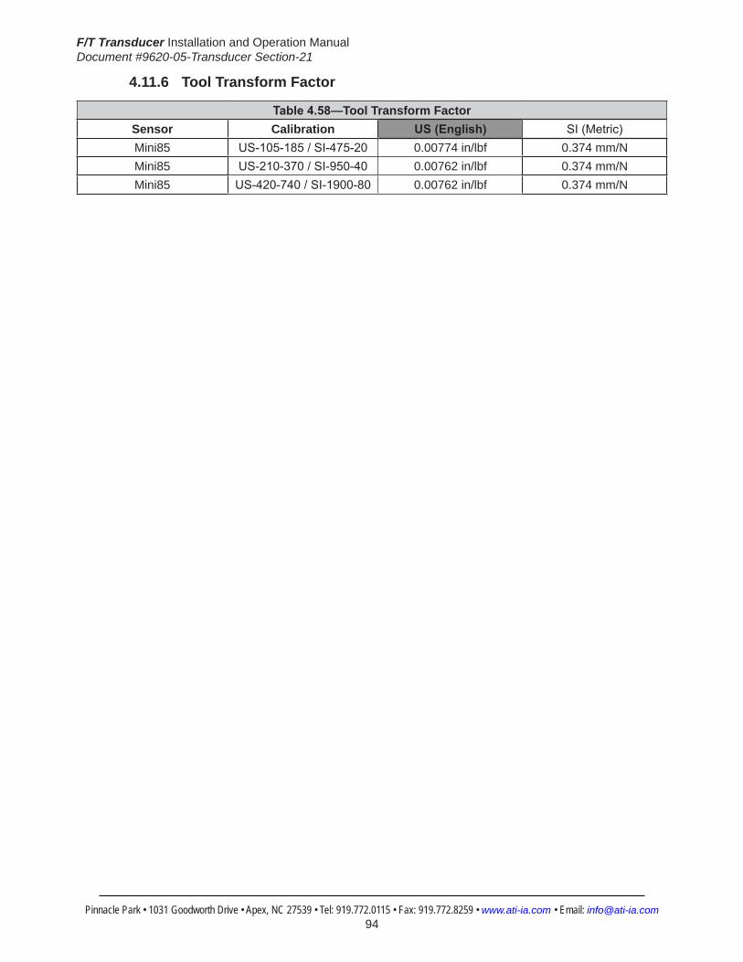
F/T Transducer Installation and Operation ManualDocument #9620-05-Transducer Section-21
Pinnacle Park • 1031 Goodworth Drive • Apex, NC 27539 • Tel: 919.772.0115 • Fax: 919.772.8259 • www.ati-ia.com • Email: [email protected] 94
4.11.6 Tool Transform Factor
Table4.58—Tool Transform FactorSensor Calibration US(English) SI(Metric)Mini85 US-105-185/SI-475-20 0.00774 in/lbf 0.374 mm/NMini85 US-210-370/SI-950-40 0.00762 in/lbf 0.374 mm/NMini85 US-420-740/SI-1900-80 0.00762 in/lbf 0.374 mm/N

F/T Transducer Installation and Operation ManualDocument #9620-05-Transducer Section-21
Pinnacle Park • 1031 Goodworth Drive • Apex, NC 27539 • Tel: 919.772.0115 • Fax: 919.772.8259 • www.ati-ia.com • Email: [email protected] 95
4.11.7 Mini85(USCalibrationComplexLoading)(IncludesIP60)
HelpMini85
US-105-185 US-210-370 US-420-740

F/T Transducer Installation and Operation ManualDocument #9620-05-Transducer Section-21
Pinnacle Park • 1031 Goodworth Drive • Apex, NC 27539 • Tel: 919.772.0115 • Fax: 919.772.8259 • www.ati-ia.com • Email: [email protected] 96
4.11.8 Mini85(SICalibrationComplexLoading)(IncludesIP60)
HelpMini85
SI-475-20 SI-950-40 SI-1900-80

F/T Transducer Installation and Operation ManualDocument #9620-05-Transducer Section-21
Pinnacle Park • 1031 Goodworth Drive • Apex, NC 27539 • Tel: 919.772.0115 • Fax: 919.772.8259 • www.ati-ia.com • Email: [email protected] 97
4.11.9 Mini85TransducerDrawing
(2)
5.06
05.
034
9.0
SLI
P F
IT
5 D
OW
EL
(SE
E N
OTE
4)
B.C
. 7
4P
AIR
S E
QU
ALL
Y
SP
AC
ED
(SE
E N
OTE
4)
(6) M
5X0.
8 9.
0
37±0
.025
71.3
06±0
.025
7.5±
0.13
TH
RU
(SE
E N
OTE
5)
13.8
60±0
.025
10°
20°
(Typ
.)
NO
TES
:1.
MO
UN
TIN
G A
ND
TO
OL
AD
AP
TER
MA
DE
OF
ALU
MIN
UM
.
TR
AN
SD
UC
ER
MA
DE
OF
HA
RD
EN
ED
STA
INLE
SS
STE
EL.
2. U
SE
M5
TAP
PE
D H
OLE
S A
ND
DO
WE
L P
IN H
OLE
S F
OR
MO
UN
TIN
G A
DA
PTE
R A
ND
TO
OL
AD
AP
TER
INTE
RFA
CIN
G.
3. W
AR
NIN
G: D
O N
OT
LOO
SEN
OR
REM
OVE
INTE
RFA
CE
P
LATE
S D
UE
TO P
OTE
NTI
AL
DA
MA
GE
4. D
O N
OT
EXC
EED
INTE
RFA
CE
DEP
TH, M
AY
CA
USE
DA
MA
GE
5. D
O N
OT
ALL
OW
ITE
MS
PA
SS
ING
TH
RO
UG
H T
O C
ON
TAC
T
EIT
HE
R S
IDE
OF
TRA
NS
DU
CE
R.
CO
NTA
CT
WIL
L A
FFE
CT
R
EA
DIN
G A
CC
UR
AC
Y.
6. W
AR
NIN
G: D
O N
OT
LOO
SE
N O
R R
EM
OV
E C
AB
LE
D
UE
TO
PO
TEN
TIA
L D
AM
AG
E.
7. C
ON
NE
CTO
R (N
OT
SH
OW
N) H
AS
17m
m D
IAM
ETE
R A
ND
IS 6
7.5m
m L
ON
G.
-X+X
-Y+Y
MO
UN
TIN
G S
IDE
29.8
10.3
11.58.
0
85
7.5
CA
BLE
EX
IT
SID
E VI
EW
MO
UN
TIN
G
AD
AP
TER
TOO
L A
DA
PTE
R
SE
NS
ING
RE
FER
EN
CE
FRA
ME
OR
IGIN
(2)
5.06
05.
034
6.5
SLI
P F
IT
5 D
OW
EL
(SE
E N
OTE
4)
40.5
00±0
.025
23.3
83±0
.025
27±0
.025
40°
40°
(Typ
.) (SE
E N
OTE
4)
SP
AC
ED
PA
IRS
EQ
UA
LLY
B
.C.
54(6
) M5X
0.8
6.
5
70°
-Z+Z
+Y
+X
-X
-Y
TOO
L SI
DE
SE
NS
ING
RE
FER
EN
CE
FRA
ME
OR
IGIN
CA
BLE
EX
IT
ISO
MET
RIC
VIE
W
Min
i85
Tran
sduc
er92
30-0
5-12
77-0
510
31 G
oodw
orth
Driv
e, A
pex,
NC
275
39, U
SATe
l: +1
.919
.772
.011
5
Em
ail:
info
@at
i-ia.
com
Fax:
+1.
919.
772.
8259
ww
w.a
ti-ia
.com
ISO
900
1 R
egis
tere
d C
ompa
ny

F/T Transducer Installation and Operation ManualDocument #9620-05-Transducer Section-21
Pinnacle Park • 1031 Goodworth Drive • Apex, NC 27539 • Tel: 919.772.0115 • Fax: 919.772.8259 • www.ati-ia.com • Email: [email protected] 98
4.11.10 Mini85-ETransducerDrawing
3rd
AN
GLE
PRO
JEC
TION
13.
860±
0.02
5
37±
0.02
5
71.
306±
0.02
5
6X T
ap M
5X0.
8 9
.0Pa
irs E
qual
ly S
pace
dC
usto
mer
Inte
rface
(See
Not
e 3) B.C
.74
20°
Typ
.
10°
MO
UN
TIN
G S
IDE
-X
-Y+Y
+X
-Z
2X5
Slip
Fit
9.0
Cus
tom
er In
terfa
ce(S
ee N
ote
3)
29.
8
85
10.
3
11.
5
7.5
Cab
leEx
it
SID
E VI
EW
+Z
Sens
ing
Ref
eren
ceFr
ame
Orig
in
Tool
Adap
ter
Plat
e
Mou
ntin
gAd
apte
rPl
ate
23.
383±
0.02
5
27±
0.02
5
40.
500±
0.02
5
40°
40°
Typ
.
6X T
ap M
5X0.
8 6
.5Pa
irs E
qual
ly S
pace
dC
usto
mer
Inte
rface
(See
Not
e 3)
B.C
.54
7
0°
TOO
L SI
DE
+X -X
-Y+Y
2X5
Slip
Fit
6.5
Cus
tom
er In
terfa
ce(S
ee N
ote
3)
Sens
ing
Ref
eren
ceFr
ame
Orig
in
ISO
MET
RIC
VIE
W
Not
es:
1. M
ater
ial:
Mou
ntin
g an
d To
ol A
dapt
er m
ade
of a
lum
inum
,
Tra
nsdu
cer m
ade
of h
arde
ned
stai
nles
s st
eel.
2. W
AR
NIN
G: D
O N
OT
LOO
SEN
OR
REM
OVE
INTE
RFA
CE
P
LATE
S O
R C
AB
LE D
UE
TO P
OTE
NTI
AL
DA
MA
GE
3. D
O N
OT
EXC
EED
INTE
RFA
CE
DEP
TH, M
AY
CA
USE
DA
MA
GE.
4. C
onne
ctor
(not
sho
wn)
has
17m
m d
iam
eter
and
is 6
7.5m
m lo
ng.
5. F
or b
est a
ccur
acy,
tran
sduc
er m
ust b
e m
ount
ed to
sur
face
rigi
d
eno
ugh
to s
uppo
rt lo
ads
with
out d
efle
ctio
n.
Rev.
Des
crip
tion
Initi
ator
Dat
e
02In
itial
Dra
win
gJW
9/5/
2011
B1:
11
1RE
VISIO
N
NO
TES:
UN
LESS
OTH
ERW
ISE
SPEC
IFIED
.
DO
NO
T SC
ALE
DRA
WIN
G.
ALL
DIM
ENSI
ON
S A
RE IN
M
ILLIM
ETER
S.
DRA
WN
BY:
CHE
CKE
D B
Y:
J. W
alse
r 08/
04/2
011
R. C
ham
bers
8/1
6/11
TITLE SC
ALE
SIZE
DRA
WIN
G N
UMBE
R
PRO
JEC
T #SH
EET
O
F 92
30-0
5-13
94-
02
PRO
PERT
Y O
F A
TI IN
DUS
TRIA
L A
UTO
MA
TION
, IN
C. N
OT T
O B
E RE
PRO
DUC
ED IN
AN
Y M
AN
NER
EXC
EPT O
N O
RDER
OR
WITH
PRI
OR
WRI
TTEN
AUT
HORI
ZATIO
N O
F A
TI.
1031
Goo
dwor
th Dr
ive, A
pex,
NC 27
539,
USA
Tel: +
1.919
.772.0
115
Em
ail: in
fo@ati
-ia.co
mFa
x: +1
.919.7
72.82
59
www
.ati-ia
.com
ISO
9001
Reg
ister
ed C
ompa
ny
Min
i85
Tran
sduc
er

F/T Transducer Installation and Operation ManualDocument #9620-05-Transducer Section-21
Pinnacle Park • 1031 Goodworth Drive • Apex, NC 27539 • Tel: 919.772.0115 • Fax: 919.772.8259 • www.ati-ia.com • Email: [email protected] 99
4.11.11 Mini85IP60Transducerwith20mmThrough-HoleDrawing
3rd
AN
GLE
PRO
JEC
TION
200+0.1
27 T
hru
(See
Not
e 4)
37±0
.025
71.3
06±0
.025
13.8
60±0
.025
6X T
ap M
5X0.
8 9
.0Pa
irs E
qual
ly S
pace
dC
usto
mer
Inte
rface
(See
Not
e 3)
B.C
.74
10°
20° T
yp.
-Z
TOO
L SI
DE
MO
UN
TIN
G S
IDE
-X+X
+Y-Y
2X5
Slip
Fit
9.0
Cus
tom
er In
terfa
ce(S
ee N
ote
3)
10.3
11.5
85
29.8
7.5
Cab
leEx
it
+Z
Mou
ntin
gAd
apte
rPl
ate
Sens
ing
Ref
eren
ceFr
ame
Orig
in
Tool
Adap
ter
Plat
e
27±0
.025
40.5
00±0
.025
23.3
83±0
.025
6X T
ap M
5X0.
8 6
.5Pa
irs E
qual
ly S
pace
dC
usto
mer
Inte
rface
(See
Not
e 3)
B.C
.54
70
°
40°
40° T
yp.
SID
E VI
EW
-Y+Y
+X
-X
Sens
ing
Ref
eren
ceFr
ame
Orig
in
2X5
Slip
Fit
6.5
Cus
tom
er In
terfa
ce(S
ee N
ote
3)
ISO
MET
RIC
VIE
W
Not
es:
1. M
ater
ial:
Mou
ntin
g an
d To
ol A
dapt
er m
ade
of a
lum
inum
,
Tra
nsdu
cer m
ade
of h
arde
ned
stai
nles
s st
eel.
2. W
AR
NIN
G: D
O N
OT
LOO
SEN
OR
REM
OVE
INTE
RFA
CE
P
LATE
S O
R C
AB
LE D
UE
TO P
OTE
NTI
AL
DA
MA
GE
3. D
O N
OT
EXC
EED
INTE
RFA
CE
DEP
TH, M
AY
CA
USE
DA
MA
GE
4. D
o no
t allo
w it
ems
pass
ing
thro
ugh
cent
er h
ole
to to
uch
both
the
M
ount
ing
and
Tool
Ada
pter
Pla
tes
or a
ccur
acy
will
be c
ompr
omis
ed.
5. C
onne
ctor
(not
sho
wn)
has
17m
m d
iam
eter
and
is 6
7.5m
m lo
ng.
6. F
or b
est a
ccur
acy,
tran
sduc
er m
ust b
e m
ount
ed to
sur
face
rigi
d
eno
ugh
to s
uppo
rt lo
ads
with
out d
efle
ctio
n.
Rev.
Des
crip
tion
Initi
ator
Dat
e
02M
odify
dra
win
g fo
rmat
to m
eet c
urre
nt st
anda
rdJW
8/30
/201
1
B1:
11
1RE
VISIO
N
NO
TES:
UN
LESS
OTH
ERW
ISE
SPEC
IFIED
.
DO
NO
T SC
ALE
DRA
WIN
G.
ALL
DIM
ENSI
ON
S A
RE IN
M
ILLIM
ETER
S.
DRA
WN
BY:
CHE
CKE
D B
Y:
R C
ham
bers
2/1
5/08
P. F
usco
5/2
2/08
TITLE SC
ALE
SIZE
DRA
WIN
G N
UMBE
R
PRO
JEC
T #SH
EET
O
F 92
30-0
5-13
2307
1026
-102
PRO
PERT
Y O
F A
TI IN
DUS
TRIA
L A
UTO
MA
TION
, IN
C. N
OT T
O B
E RE
PRO
DUC
ED IN
AN
Y M
AN
NER
EXC
EPT O
N O
RDER
OR
WITH
PRI
OR
WRI
TTEN
AUT
HORI
ZATIO
N O
F A
TI.
1031
Goo
dwor
th Dr
ive, A
pex,
NC 27
539,
USA
Tel: +
1.919
.772.0
115
Em
ail: in
fo@ati
-ia.co
mFa
x: +1
.919.7
72.82
59
www
.ati-ia
.com
ISO
9001
Reg
ister
ed C
ompa
ny
Min
i85
Tran
sduc
er w
ith 2
0mm
Thr
u H
ole

F/T Transducer Installation and Operation ManualDocument #9620-05-Transducer Section-21
Pinnacle Park • 1031 Goodworth Drive • Apex, NC 27539 • Tel: 919.772.0115 • Fax: 919.772.8259 • www.ati-ia.com • Email: [email protected] 100
4.12 GammaSpecifications(IncludesIP60/IP65/IP68Versions)4.12.1 Gamma Physical Properties
Table 4.59—Gamma Physical PropertiesSingle-Axis Overload (US)StandardUnits (SI)MetricUnitsFxy ±280 lbf ±1200 NFz ±930 lbf ±4100 NTxy ±700 inf-lb ±79 NmTz ±730 inf-lb ±82 NmStiffness(Calculated) X-axis&Y-axisforces(Kx,Ky) 5.2x10⁴ lb/in 9.1x10⁶ N/m Z-axisforce(Kz) 1.0x10⁵ lb/in 1.8x10⁷ N/m X-axis&Y-axistorque(Ktx,Kty) 9.3x10⁴ lbf-in/rad 1.1x10⁴ Nm/rad Z-axistorque(Ktz) 1.4x10⁵ lbf-in/rad 1.6x10⁴ Nm/rad Resonant Frequency Fx, Fy, Tz 1400 Hz 1400 HzFz, Tx, Ty 2000 Hz 2000 HzPhysicalSpecifications Weight1 0.562 lb 0.255 kgDiameter1 2.97 in 75.4 mmHeight1 1.31 in 33.3 mmNote: 1.Specificationsincludestandardinterfaceplates.
4.12.2 Gamma IP60 Physical PropertiesTable 4.60—Gamma IP60 Physical Properties
Single-Axis Overload (US)StandardUnits (SI)MetricUnitsFxy ±280 lbf ±1200 NFz ±930 lbf ±4100 NTxy ±700 inf-lb ±79 NmTz ±730 inf-lb ±82 NmStiffness(Calculated) X-axis&Y-axisforces(Kx,Ky) 5.2x10⁴ lb/in 9.1x10⁶ N/m Z-axisforce(Kz) 1.0x10⁵ lb/in 1.8x10⁷ N/m X-axis&Y-axistorque(Ktx,Kty) 9.3x10⁴ lbf-in/rad 1.1x10⁴ Nm/rad Z-axistorque(Ktz) 1.4x10⁵ lbf-in/rad 1.6x10⁴ Nm/rad Resonant Frequency Fx, Fy, Tz 1200 Hz 1200 HzFz, Tx, Ty 1200 Hz 1200 HzPhysicalSpecifications Weight1 1.03 lb 0.467 kgDiameter1 3.9 in 99.1 mmHeight1 1.56 in 39.6 mmNote: 1.Specificationsincludestandardinterfaceplates.

F/T Transducer Installation and Operation ManualDocument #9620-05-Transducer Section-21
Pinnacle Park • 1031 Goodworth Drive • Apex, NC 27539 • Tel: 919.772.0115 • Fax: 919.772.8259 • www.ati-ia.com • Email: [email protected] 101
4.12.3 Gamma IP65 Physical PropertiesTable 4.61—Gamma IP65 Physical Properties
Single-Axis Overload (US)StandardUnits (SI)MetricUnitsFxy ±280 lbf ±1200 NFz ±930 lbf ±4100 NTxy ±700 inf-lb ±79 NmTz ±730 inf-lb ±82 NmStiffness(Calculated) X-axis&Y-axisforces(Kx,Ky) 5.2x10⁴ lb/in 9.1x10⁶ N/m Z-axisforce(Kz) 1.0x10⁵ lb/in 1.8x10⁷ N/m X-axis&Y-axistorque(Ktx,Kty) 9.3x10⁴ lbf-in/rad 1.1x10⁴ Nm/rad Z-axistorque(Ktz) 1.4x10⁵ lbf-in/rad 1.6x10⁴ Nm/rad Resonant Frequency Fx, Fy, Tz 1000 Hz 1000 HzFz, Tx, Ty 970 Hz 970 HzPhysicalSpecifications Weight1 2.4 lb 1.09 kgDiameter1 4.37 in 111 mmHeight1 2.06 in 52.3 mmNote: 1.Specificationsincludestandardinterfaceplates.
4.12.4 GammaIP68PhysicalPropertiesTable 4.62—GammaIP68PhysicalProperties
Single-Axis Overload (US)StandardUnits (SI)MetricUnitsFxy ±280 lbf ±1200 NFz ±930 lbf ±4100 NTxy ±700 inf-lb ±79 NmTz ±730 inf-lb ±82 NmStiffness(Calculated) X-axis&Y-axisforces(Kx,Ky) 5.2x10⁴ lb/in 9.1x10⁶ N/m Z-axisforce(Kz) 1.0x10⁵ lb/in 1.8x10⁷ N/m X-axis&Y-axistorque(Ktx,Kty) 9.3x10⁴ lbf-in/rad 1.1x10⁴ Nm/rad Z-axistorque(Ktz) 1.4x10⁵ lbf-in/rad 1.6x10⁴ Nm/rad Resonant Frequency Fx, Fy, Tz 1250 Hz 1250 HzFz, Tx, Ty 940 Hz 940 HzPhysicalSpecifications Weight1 4.37 lb 1.98 kgDiameter1 4.37 in 111 mmHeight1 2.06 in 52.3 mmNote: 1.Specificationsincludestandardinterfaceplates.

F/T Transducer Installation and Operation ManualDocument #9620-05-Transducer Section-21
Pinnacle Park • 1031 Goodworth Drive • Apex, NC 27539 • Tel: 919.772.0115 • Fax: 919.772.8259 • www.ati-ia.com • Email: [email protected] 102
CAUTION: When submerged, IP68 transducers exhibit a decrease in Fz range related to the submersion depth. This loss is the result of pressure-induced preloading on the transducer. The preload can be masked by biasing the transducer at the depth prior to applying the load to be measured. The following estimates are for room temperature fresh water at sea level.
Submersion DepthIP68Gamma US MetricFz preload at 4 m depth -42.9 lb -191 NFz preload at other depths -3.27 lb/ft × depthInFeet -47.4 N/m × depthInMeters
4.12.5 CalibrationSpecifications(excludesCTLcalibrations)Table 4.63—GammaCalibrations(excludesCTLcalibrations)1, 2
Sensor (US)Standard Calibration
Fx,Fy (lbf)
Fz3 (lbf)
Tx,Ty (lbf-in)
Tz (lbf-in)
Fx,Fy (lbf)
Fz3 (lbf)
Tx,Ty (lbf-in)
Tz (lbf-in)
Gamma US-7.5-25 7.5 25 25 25 1/640 1/320 1/320 1/320Gamma US-15-50 15 50 50 50 1/320 1/160 1/160 1/160Gamma US-30-100 30 100 100 100 1/160 1/80 1/80 1/80
Sensor (SI)Metric Calibration
Fx,Fy (N)
Fz3 (N)
Tx,Ty (Nm)
Tz (Nm)
Fx,Fy (N)
Fz3 (N)
Tx,Ty (Nm)
Tz (Nm)
Gamma SI-32-2.5 32 100 2.5 2.5 1/160 1/80 1/2000 1/2000Gamma SI-65-5 65 200 5 5 1/80 1/40 10/13333 10/13333Gamma SI-130-10 130 400 10 10 1/40 1/20 1/800 1/800
Sensing Ranges Resolution(DAQ,NetF/T)4
Notes: 1. These system resolutions quoted are the effective resolution after dropping four counts of noise. Theeffectiveresolutioncanbeimprovedwithfiltering. 2. Applied loads must be within range in each of the six axes for the F/T sensor to measure correctly. 3. For IP68 version see caution on physical properties page. 4. DAQ resolutions are typical for a 16-bit data acquisition system.

F/T Transducer Installation and Operation ManualDocument #9620-05-Transducer Section-21
Pinnacle Park • 1031 Goodworth Drive • Apex, NC 27539 • Tel: 919.772.0115 • Fax: 919.772.8259 • www.ati-ia.com • Email: [email protected] 103
4.12.6 CTLCalibrationSpecificationsTable 4.64— Gamma CTL Calibrations1, 2
Sensor (US)Standard Calibration
Fx,Fy (lbf)
Fz3 (lbf)
Tx,Ty (lbf-in)
Tz (lbf-in)
Fx,Fy (lbf)
Fz3 (lbf)
Tx,Ty (lbf-in)
Tz (lbf-in)
Gamma US-7.5-25 7.5 25 25 25 1/320 1/160 1/160 1/160Gamma US-15-50 15 50 50 50 1/160 1/80 1/80 1/80Gamma US-30-100 30 100 100 100 1/80 1/40 1/40 1/40
Sensor (SI)Metric Calibration
Fx,Fy (N)
Fz3 (N)
Tx,Ty (Nm)
Tz (Nm)
Fx,Fy (N)
Fz3 (N)
Tx,Ty (Nm)
Tz (Nm)
Gamma SI-32-2.5 32 100 2.5 2.5 1/80 1/40 1/1000 1/1000Gamma SI-65-5 65 200 5 5 1/40 1/20 5/3333 5/3333Gamma SI-130-10 130 400 10 10 1/20 1/10 1/400 1/400
Sensing Ranges Resolution(Controller)Notes: 1. CTL resolutions are typical. System resolutions quoted are the effective resolution after dropping eight countsofnoise.Theeffectiveresolutioncanbeimprovedwithfiltering. 2. Applied loads must be within range in each of the six axes for the F/T sensor to measure correctly. 3. For IP68 version see caution on physical properties page.
4.12.7 Analog OutputTable 4.65— Gamma Analog Output
Sensor (US)Standard Calibration
Fx,Fy (lbf)
Fz2 (lbf)
Tx,Ty,Tz (lbf-in)
Fx,Fy (lbf/V)
Fz2 (lbf/V)
Tx,Ty,Tz (lbf-in/V)
Gamma US-7.5-25 ±7.5 ±25 ±25 0.75 2.5 2.5Gamma US-15-50 ±15 ±50 ±50 1.5 5 5Gamma US-30-100 ±30 ±100 ±100 3 10 10
Sensor (SI)Metric Calibration
Fx,Fy (N)
Fz2 (N)
Tx,Ty,Tz (Nmm)
Fx,Fy (N/V)
Fz2 (N/V)
Tx,Ty,Tz (Nm/V)
Gamma SI-32-2.5 ±32 ±100 ±2.5 3.2 10 0.25Gamma SI-65-5 ±65 ±200 ±5 6.5 20 0.5Gamma SI-130-10 ±130 ±400 ±10 13 40 1
Analog Output Range Analog±10VSensitivity1
Notes: 1. ±5V Sensitivity values are double the listed ±10V Sensitivity values. 2. For IP68 version see caution on physical properties page.

F/T Transducer Installation and Operation ManualDocument #9620-05-Transducer Section-21
Pinnacle Park • 1031 Goodworth Drive • Apex, NC 27539 • Tel: 919.772.0115 • Fax: 919.772.8259 • www.ati-ia.com • Email: [email protected] 104
4.12.8 CountsValueTable 4.66—CountsValue
Sensor Calibration Fx,Fy,Fz (/lbf)
Tx,Ty,Tz (/lbf-in)
Fx,Fy,Fz (/N)
Tx,Ty,Tz (/Nm)
Gamma US-7.5–25/SI-32–2.5 2560 2560 640 8000Gamma US-15–50/SI-65–5 1280 1280 320 5333.33Gamma US-30–100/SI-130–10 640 640 160 3200Gamma Tool Transform Factor See Tool Transform Factor table
CountsValue–Standard(US) CountsValue–Metric(SI)
4.12.9 Tool Transform FactorTable 4.67—Tool Transform Factor
Sensor Calibration US(English) SI(Metric)Gamma US-7.5–25/SI-32–2.5 0.01 in/lbf 0.8 mm/NGamma US-15–50/SI-65–5 0.01 in/lbf 0.6 mm/NGamma US-30–100/SI-130–10 0.01 in/lbf 0.y h5 mm/N
.
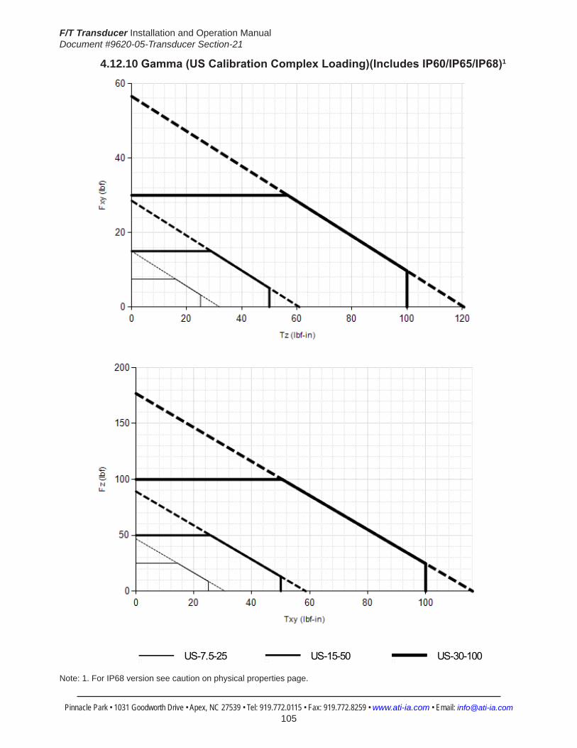
F/T Transducer Installation and Operation ManualDocument #9620-05-Transducer Section-21
Pinnacle Park • 1031 Goodworth Drive • Apex, NC 27539 • Tel: 919.772.0115 • Fax: 919.772.8259 • www.ati-ia.com • Email: [email protected] 105
4.12.10 Gamma(USCalibrationComplexLoading)(IncludesIP60/IP65/IP68)1
HelpGamma
US-7.5-25 US-15-50 US-30-100
Note: 1. For IP68 version see caution on physical properties page.

F/T Transducer Installation and Operation ManualDocument #9620-05-Transducer Section-21
Pinnacle Park • 1031 Goodworth Drive • Apex, NC 27539 • Tel: 919.772.0115 • Fax: 919.772.8259 • www.ati-ia.com • Email: [email protected] 106
4.12.11 Gamma(SICalibrationComplexLoading)(IncludesIP60/IP65/IP68)1
HelpGamma
SI-32-2.5 SI-65-5 SI-130-10
Note: 1. For IP68 version see caution on physical properties page.

F/T Transducer Installation and Operation ManualDocument #9620-05-Transducer Section-21
Pinnacle Park • 1031 Goodworth Drive • Apex, NC 27539 • Tel: 919.772.0115 • Fax: 919.772.8259 • www.ati-ia.com • Email: [email protected] 107
4.12.12 GammaDAQ/NetTransducerDrawing
25.5
DAQ
Sys
tem
54.8
DAQ
Sys
tem
30°
32.8
Net
Sys
tem
58.3
Net
Sys
tem
MO
UN
TIN
G S
IDE
Cus
tom
er m
achi
nes
mou
ntin
g pa
ttern
as n
eede
d in
pla
te.
Rem
ove
plat
e pr
ior
to m
achi
ning
.+X -X
-Y+Y
Con
nect
or fo
r Cab
leVa
ries
Dep
endi
ng o
n Se
nsor
Sel
ecte
d
6074
28.6
33.3 28
75.4
19.8
0.8
+Z-Z
Sens
ing
Ref
eren
ceFr
ame
Orig
in
SID
E VI
EW
Mou
ntin
gAd
apte
rPl
ate
Tool
Adap
ter
Plat
e
25±0
.025
45°
B.C
. 50
6 Sl
ip F
it 5.
6C
usto
mer
Inte
rface
(See
Not
e 3)
16 H
7 3.
61.
0 x
45 C
ham
fer
Cus
tom
er In
terfa
ce
(4) T
ap M
6 x
1.0
5.6
Equa
lly S
pace
dC
usto
mer
Inte
rface
(See
Not
e 3)
Sens
ing
Ref
eren
ceFr
ame
Orig
in
+X -X
-Y+Y
TOO
L SI
DE
ISO
MET
RIC
VIE
WN
otes
:1.
Mat
eria
l: Al
umin
um.
2. D
o N
ot T
ouch
inte
rnal
ele
ctro
nics
or i
nstru
men
tatio
n
this
cou
ld d
amag
e th
e tra
nsdu
cer a
nd w
ill vo
id th
e w
arra
nty.
3. D
O N
OT
EXC
EED
INTE
RFA
CE
DEP
TH, M
AY
CA
USE
DA
MA
GE.
4. T
rans
duce
r mus
t be
mou
nted
to s
urfa
ces
rigid
eno
ugh
to
sup
port
load
s w
ithou
t def
lect
ion
for b
est a
ccur
acy.
Rev.
Des
crip
tion
Initi
ator
Dat
e
02C
ombi
natio
n D
raw
ing
for D
AQ
and
NET
CC
S1/
20/2
010
B1:
11
1
REVI
SION
NO
TES:
UN
LESS
OTH
ERW
ISE
SPEC
IFIED
DO
NO
T SC
ALE
DRA
WIN
G.
DRA
WN
IN S
OLID
WO
RKS.
ALL
DIM
ENSI
ON
S A
RE IN
MILL
IMET
ERS.
3rd
AN
GLE
PRO
JEC
TION
DRA
WN
BY:
CHE
CKE
D B
Y:
WEI
GHT
LBS
:
ASS
EMBL
Y RE
F:
D. S
wan
son
11/0
5/08
R. C
ham
bers
11/
06/0
8TITLE SC
ALE
SIZE
DRA
WIN
G N
UMBE
R
PRO
DUC
T REL
EASE
#SH
EET
O
F
9230
-05-
1329
B1:
11
1
------
-----
REVI
SION
02
PRO
PERT
Y O
F A
TI IN
DUS
TRIA
L A
UTO
MA
TION
, IN
C. N
OT T
O B
E RE
PRO
DUC
ED IN
AN
Y M
AN
NER
EXC
EPT O
N O
RDER
OR
WITH
PRI
OR
WRI
TTEN
AUT
HORI
ZATIO
N O
F A
TI.
1031
Goo
dwor
th Dr
ive, A
pex,
NC 27
539,
USA
Tel: +
1.919
.772.0
115
Em
ail: in
fo@ati
-ia.co
mFa
x: +1
.919.7
72.82
59
www
.ati-ia
.com
ISO
9001
Reg
ister
ed C
ompa
ny
Gam
ma
Tran
sduc
er DA
TE:

F/T Transducer Installation and Operation ManualDocument #9620-05-Transducer Section-21
Pinnacle Park • 1031 Goodworth Drive • Apex, NC 27539 • Tel: 919.772.0115 • Fax: 919.772.8259 • www.ati-ia.com • Email: [email protected] 108
4.12.13 9105-T-Gamma Transducer without Mounting Adapter Drawing
21
29.5
3.8
Cus
tom
er In
terfa
ce
(8) T
ap M
3-0.
511
Equa
lly S
pace
d
61 H
7 FI
T 1.
3C
ham
fer .
63 x
45
Cus
tom
er In
terfa
ce(S
ee N
ote
4)
3 D
owel
Pin
34±0
.025
22.5
°
68 B
.C.
Righ
t-Ang
leC
onne
ctor
+X
+Y-Y
-X
MO
UNTIN
G S
IDE
EXPO
SED
CIR
CUI
TRY
IN TH
IS A
REA
DO
NO
T TO
UCH
6074
2828.6
4.7M
ax
+Z-Z
Tool
Ada
ptor
Plat
eSI
DE
VIEW
Sens
ing
Refe
renc
eFr
ame
Orig
in
6 Sli
p Fit
5
.6C
usto
mer
Inte
rface
(See
Not
e 4)
16 H
7 3
.6C
ham
fer 1
.0 x
45
Cus
tom
er In
terfa
ce
25±0
.025
45°
50 B
.C.
(4) T
ap M
6 x
1.0
5.6
Equa
lly S
pace
dC
usto
mer
Inte
rface
(See
Not
e 4)
TOO
L SI
DE
-Y+Y
+X -X
Sens
ing
Refe
renc
eFr
ame
Orig
in
ISO
MET
RIC
VIE
W
NO
TES:
1. M
ater
ial:
Alu
min
um.
2. D
O N
OT T
OUC
H IN
TERN
AL
ELEC
TRO
NIC
S O
R IN
STRU
MEN
TATIO
N
THIS
CO
ULD
DA
MA
GE
THE
TRA
NSD
UCER
AN
D W
ILL V
OID
THE
WA
RRA
NTY
.3.
Tool
Sid
e RI
NG
-PLU
G O
ptio
n M
oves
Orig
in. S
ee
923
0-05
-105
9 fo
r Pos
ition
.4.
DO
NO
T EXC
EED
INTE
RFAC
E DE
PTH,
MAY
CAU
SE D
AMAG
E5.
Tran
sduc
er m
ust b
e m
ount
ed to
surfa
ces r
igid
eno
ugh
to
supp
ort l
oads
with
out d
efle
ctio
n fo
r bes
t acc
urac
y.
Rev.
Des
crip
tion
Initi
ator
Dat
e
07Ec
o 75
40; S
how
n w
/o M
AP
CC
S1/
29/2
010
B1:
11
1
REVI
SION
NO
TES:
UN
LESS
OTH
ERW
ISE
SPEC
IFIED
DO
NO
T SC
ALE
DRA
WIN
G.
DRA
WN
IN S
OLID
WO
RKS.
ALL
DIM
ENSI
ON
S A
RE IN
MILL
IMET
ERS.
3rd
AN
GLE
PRO
JEC
TION
DRA
WN
BY:
CHE
CKE
D B
Y:
WEI
GHT
LBS
:
ASS
EMBL
Y RE
F:
B. D
iges
o 3/
3/00
D. N
orto
n 7/
15/0
5
TITLE SC
ALE
SIZE
DRA
WIN
G N
UMBE
R
PRO
DUC
T REL
EASE
#SH
EET
O
F
9230
-05-
1103
B1:
11
1-
REVI
SION
07
PRO
PERT
Y O
F A
TI IN
DUS
TRIA
L A
UTO
MA
TION
, IN
C. N
OT T
O B
E RE
PRO
DUC
ED IN
AN
Y M
AN
NER
EXC
EPT O
N O
RDER
OR
WITH
PRI
OR
WRI
TTEN
AUT
HORI
ZATIO
N O
F A
TI.
1031
Goo
dwor
th Dr
ive, A
pex,
NC 27
539,
USA
Tel: +
1.919
.772.0
115
Em
ail: in
fo@ati
-ia.co
mFa
x: +1
.919.7
72.82
59
www
.ati-ia
.com
ISO
9001
Reg
ister
ed C
ompa
ny
Gam
ma
Tran
sduc
er w
ithou
t Mou
ntin
g A
dapt
er
DA
TE:
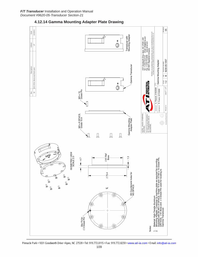
F/T Transducer Installation and Operation ManualDocument #9620-05-Transducer Section-21
Pinnacle Park • 1031 Goodworth Drive • Apex, NC 27539 • Tel: 919.772.0115 • Fax: 919.772.8259 • www.ati-ia.com • Email: [email protected] 109
4.12.14 Gamma Mounting Adapter Plate Drawing
3rd
AN
GLE
PRO
JEC
TION
M3
x 8
SFH
CS,
Gra
de 1
0.9
Gam
ma
Mou
ntin
gAd
apte
r Pla
te
M3
x 10
,D
owel
Pin
Gam
ma
Tran
sduc
er
Slip
Fit
for
3 D
owel
Pin
8X C
ount
ersi
nk h
oles
for
M3
SFH
CS
C L
1.3
75.4
61 R
efBo
ss
4.7
Tran
sduc
er w
ithM
ount
ing
Adap
ter
ISO
MET
RIC
VIE
WSC
ALE
2:3
Not
es: Mat
eria
l: H
igh-
Tens
ile A
lum
inum
1.M
ount
ing
Adap
ter:
Cus
tom
er to
mac
hine
pla
te a
s re
quire
d fo
r mou
ntin
g.2.
Supp
lied
with
8X
M3
x 8
SFH
CS,
Gra
de 1
0.9
and
1X M
3 x
10 D
owel
Pin
, D
IN 6
325.
61
Bos
s an
d 3
Dow
el P
in u
sed
for l
ocat
ing
to
Gam
ma
Tran
sduc
er.
Rev.
Des
crip
tion
Initi
ator
Dat
e
05EC
O 9
076:
Rem
oved
fini
sh sp
ecLT
F2/
2/20
12
B1:
21
1RE
VISIO
N
NO
TES:
UN
LESS
OTH
ERW
ISE
SPEC
IFIED
.
DO
NO
T SC
ALE
DRA
WIN
G.
ALL
DIM
ENSI
ON
S A
RE IN
M
ILLIM
ETER
S.
DRA
WN
BY:
CHE
CKE
D B
Y:
C. F
leso
ck, 3
/16/
2009
P. F
usco
, 3/1
7/20
09
TITLE SC
ALE
SIZE
DRA
WIN
G N
UMBE
R
PRO
JEC
T #SH
EET
O
F 92
30-0
5-10
5705
PRO
PERT
Y O
F A
TI IN
DUS
TRIA
L A
UTO
MA
TION
, IN
C. N
OT T
O B
E RE
PRO
DUC
ED IN
AN
Y M
AN
NER
EXC
EPT O
N O
RDER
OR
WITH
PRI
OR
WRI
TTEN
AUT
HORI
ZATIO
N O
F A
TI.
1031
Goo
dwor
th Dr
ive, A
pex,
NC 27
539,
USA
Tel: +
1.919
.772.0
115
Em
ail: in
fo@ati
-ia.co
mFa
x: +1
.919.7
72.82
59
www
.ati-ia
.com
ISO
9001
Reg
ister
ed C
ompa
ny
Gam
ma
Mou
ntin
g Ad
apte
r

F/T Transducer Installation and Operation ManualDocument #9620-05-Transducer Section-21
Pinnacle Park • 1031 Goodworth Drive • Apex, NC 27539 • Tel: 919.772.0115 • Fax: 919.772.8259 • www.ati-ia.com • Email: [email protected] 110
4.12.15 Gamma IP60 Transducer Drawing
3rd
AN
GLE
PRO
JEC
TION
66±0
.025
Cus
tom
er In
terfa
ceEq
ually
Spa
ced
For M
6 SH
CS
(4)
6.8
Thr
u
73.4
50.2
DAQ
Sys
tem
120°
B.C
. 88
44±0
.025
16°
38.1
05±0
.025
61°
58.6
Net
Sys
tem
+X
-Y
-X
+Y
MO
UN
TIN
G S
IDE
Con
nect
or F
or C
able
Va
ries
Dep
endi
ng o
nSe
nsor
Sel
ecte
d
2X
5 Sl
ip F
it Th
ruC
usto
mer
Inte
rface
4.7
39.6
6
38.5
DAQ
Sys
tem
32.6
6N
et S
yste
m
Sens
ing
Ref
eren
ceFr
ame
Orig
in
Neo
pren
e R
ubbe
rD
ust J
acke
t
-Z+Z
Mou
ntin
gAd
apte
r Pla
te
SID
E VI
EW
Tool
Ada
pter
Plat
e
99
74
B.C
. 50
25±0
.025
45°
Cus
tom
er In
terfa
ceEq
ually
Spa
ced
(4) T
ap M
6X1.
07
+X
-X
-Y+Y
Sens
ing
Ref
eren
ceFr
ame
Orig
inTO
OL
SID
E
16
H7
3.5
1.0x
45 C
ham
fer
Cus
tom
er In
terfa
ce
6
Slip
Fit
8.5
Cus
tom
er In
terfa
ce
ISO
MET
RIC
VIE
WN
otes
: Mat
eria
l: St
ainl
ess
Stee
l and
Alu
min
um1.
Sens
ing
Ref
eren
ce F
ram
e O
rigin
at s
urfa
ce c
ente
r of T
ool A
dapt
er.
2.D
o no
t dis
asse
mbl
e tra
nsdu
cer.
Doi
ng s
o co
uld
dam
age
trans
ucer
3.an
d w
ill vo
id w
arra
nty.
For b
est a
ccur
acy,
tran
sduc
er m
ust b
e m
ount
ed to
a s
urfa
ce ri
gid
4.en
ough
to s
uppo
rt lo
ads
with
out d
efle
ctio
n.
Rev.
Des
crip
tion
Initi
ator
Dat
e
03A
dded
Net
dim
ensio
nsRK
C5/
13/2
009
04Ec
o 15
243;
Cor
rect
ed d
im 3
9.66
, 32.
66, 6
mm
and
5m
m d
owel
s, up
date
d no
tes
RTD
1/27
/201
7
B1:
11
1RE
VISIO
N
NO
TES:
UN
LESS
OTH
ERW
ISE
SPEC
IFIED
.
DO
NO
T SC
ALE
DRA
WIN
G.
ALL
DIM
ENSI
ON
S A
RE IN
M
ILLIM
ETER
S.
DRA
WN
BY:
CHE
CKE
D B
Y:
R. C
ham
bers
6/2
5/08
P.Fu
sco
6/26
/08
TITLE SC
ALE
SIZE
DRA
WIN
G N
UMBE
R
PRO
JEC
T #SH
EET
O
F 92
30-0
5-13
3508
0602
-104
PRO
PERT
Y O
F A
TI IN
DUS
TRIA
L A
UTO
MA
TION
, IN
C. N
OT T
O B
E RE
PRO
DUC
ED IN
AN
Y M
AN
NER
EXC
EPT O
N O
RDER
OR
WITH
PRI
OR
WRI
TTEN
AUT
HORI
ZATIO
N O
F A
TI.
1031
Goo
dwor
th Dr
ive, A
pex,
NC 27
539,
USA
Tel: +
1.919
.772.0
115
Em
ail: in
fo@ati
-ia.co
mFa
x: +1
.919.7
72.82
59
www
.ati-ia
.com
ISO
9001
Reg
ister
ed C
ompa
ny
IP60
Gam
ma
Tran
sduc
er

F/T Transducer Installation and Operation ManualDocument #9620-05-Transducer Section-21
Pinnacle Park • 1031 Goodworth Drive • Apex, NC 27539 • Tel: 919.772.0115 • Fax: 919.772.8259 • www.ati-ia.com • Email: [email protected] 111
4.12.16 Gamma IP65 Transducer Drawing
3rd
AN
GLE
PRO
JEC
TION
70.7
Net
Sys
tem
B.C
.63
31.0
21±0
.025
31.5
00±0
.025
B.C
.98
Side
Pat
tern
Opt
iona
l Mou
nitn
gC
usto
mer
Inte
rface
Equa
lly S
pace
dFo
r M6
SHC
S(4
) 6
.6 T
hru
82.2
Mux
, DAQ
& T
WL
Syst
em
45°
100°
Cus
tom
er In
terfa
ceEq
ually
Spa
ced
(4) T
ap M
6X1
7
45°
(2)
4 S
lip F
it 6
Cus
tom
er In
terfa
ce
36.
970±
0.02
5
63.3
Mux
, DAQ
& T
WL
Syst
em75
.2N
et S
yste
m
MO
UN
TIN
G S
IDE+X -X
+Y-Y
Con
nect
or fo
r Cab
leVa
ries
Dep
endi
ng o
nSe
nsor
Sel
ecte
d
44.2
78.7
1.4
6.5
46.7
52.2
SID
E VI
EW
+Z
Sens
ing
Ref
eren
ceFr
ame
Orig
in 85.6
B.C
.50
Cus
tom
er In
terfa
ceEq
ually
Spa
ced
(4) T
ap M
6X1
8.5
Cus
tom
er In
terfa
ce 6
Slip
Fit
6
25±0
.025
16 H
76
Cha
mfe
r 0.6
x 4
5C
usto
mer
Inte
rface
45°
111
TOO
L SI
DE
-Z+Y
-Y
-X
Sens
ing
Ref
eren
ceFr
ame
Orig
in
ISO
MET
RIC
VIE
W
Not
es:
1. M
ater
ial:
Alum
inum
and
Sta
inle
ss S
teel
2. S
ensi
ng R
efer
ence
Fra
me
Orig
in a
t
sur
face
cen
ter o
f Too
l Ada
pter
.3.
Do
not d
isas
sem
ble
trans
duce
r. D
oing
so
c
ould
dam
age
trans
duce
r and
will
void
w
arra
nty.
4. F
or b
est a
ccur
acy,
tran
sduc
er m
ust b
e
mou
nted
to s
urfa
ces
rigid
eno
ugh
to s
uppo
rt
load
s w
ithou
t def
lect
ion.
5.
Cab
le m
ust b
e co
nnec
ted
to T
rans
duce
r to
m
aint
ain
prop
er s
eal.
6. C
able
is IP
65 ra
ted
only
at T
rans
duce
r End
.
+X
Rev.
Des
crip
tion
Initi
ator
Dat
e
03A
dded
Net
Dim
ensio
ns.
ALH
8/8/
2008
04Ec
o 16
104;
Add
ed TW
L D
imen
sions
RTD
9/18
/201
7
B1:
11
1RE
VISIO
N
NO
TES:
UN
LESS
OTH
ERW
ISE
SPEC
IFIED
.
DO
NO
T SC
ALE
DRA
WIN
G.
ALL
DIM
ENSI
ON
S A
RE IN
M
ILLIM
ETER
S.
DRA
WN
BY:
CHE
CKE
D B
Y:
P. F
usco
12/
15/0
6
D. S
wan
son
12/1
8/06
TITLE SC
ALE
SIZE
DRA
WIN
G N
UMBE
R
PRO
JEC
T #SH
EET
O
F 92
30-0
5-13
0706
0612
-104
PRO
PERT
Y O
F A
TI IN
DUS
TRIA
L A
UTO
MA
TION
, IN
C. N
OT T
O B
E RE
PRO
DUC
ED IN
AN
Y M
AN
NER
EXC
EPT O
N O
RDER
OR
WITH
PRI
OR
WRI
TTEN
AUT
HORI
ZATIO
N O
F A
TI.
1031
Goo
dwor
th Dr
ive, A
pex,
NC 27
539,
USA
Tel: +
1.919
.772.0
115
Em
ail: in
fo@ati
-ia.co
mFa
x: +1
.919.7
72.82
59
www
.ati-ia
.com
ISO
9001
Reg
ister
ed C
ompa
ny
IP65
Gam
ma
Tran
sduc
er

F/T Transducer Installation and Operation ManualDocument #9620-05-Transducer Section-21
Pinnacle Park • 1031 Goodworth Drive • Apex, NC 27539 • Tel: 919.772.0115 • Fax: 919.772.8259 • www.ati-ia.com • Email: [email protected] 112
4.12.17 ECAT Gamma IP65 Transducer Drawing
3rd
AN
GLE
PRO
JEC
TION
68.
3
11
1.0
31.
021±
0.02
5
36.
970±
0.02
5
31.
500±
0.02
5
2X
4 S
lip F
it 6
Cus
tom
er In
terfa
ce
4X T
ap M
6X1
7E
qual
ly S
pace
dC
usto
mer
Inte
rface
4X
6.6
Thru
For M
6 S
HC
SE
qual
ly S
pace
d C
usto
mer
Inte
rface
Opt
iona
l Mou
ntin
g S
ide
Pat
tern
75.
2
45°
B.C
.98
.0
100
°
135
°
B.C
.63
.0
+X
-X
-Y+Y
+Y
-X
-Y
+X
DC
Pow
er
Eth
erC
AT
(Opt
iona
l PoE
)
52.
2
44.
3
5.5
78
.7
7.9
1
.4
46.
7
Mou
ntin
g A
dapt
erP
late
Tool
Ada
pter
Pla
te
Rin
g Te
rmin
al(F
or O
ptio
nal
Ear
th G
roun
dC
onne
ctio
n)
Eth
erC
AT
LED
Indi
cato
rs
+Z-Z
Sen
sing
Ref
eren
ceFr
ame
Orig
in
4X T
ap M
6X1
8.5
Equ
ally
Spa
ced
Cus
tom
er In
terfa
ce
6 S
lip F
it 6
Cus
tom
er In
terfa
ce
25.
000±
0.02
5
16 H
76
Cha
mfe
r 0.6
X 4
5C
usto
mer
Inte
rface
85
.6
B.C
.50
.0
45°
Pre
ssur
e E
quili
zatio
n V
ent,
IP65
Sen
sing
Ref
eren
ceFr
ame
Orig
in
Not
es:
Mat
eria
l: A
lum
inum
and
Sta
inle
ss S
teel
1.S
ensi
ng R
efer
ence
Fra
me
Orig
in a
t sur
face
cen
ter o
f Too
l Ada
pter
.2.
Do
not d
isas
sem
ble
trans
duce
r. D
oing
so
coul
d da
mag
e tra
nsdu
cer a
nd w
ill v
oid
war
rant
y.3.
For b
est a
ccur
acy,
tran
sduc
er m
ust b
e m
ount
ed to
a s
urfa
ce ri
gid
enou
gh to
sup
port
load
s4.
with
out d
efle
ctio
n.C
able
s m
ust b
e co
nnec
ted
to tr
ansd
ucer
to m
anta
in p
rope
r sea
l.5.
Cab
les
are
IP65
rate
d on
ly a
t tra
nsdu
cer e
nd.
6.
MO
UN
TIN
G S
IDE
TOO
L S
IDE
SID
E V
IEW
Rev.
Des
crip
tion
Initi
ator
Dat
e
01In
itial
Rel
ease
RTD
11/2
3/20
16
B1:
21
2RE
VISI
ON
NO
TES:
UN
LESS
OTH
ERW
ISE
SPEC
IFIE
D.
DO
NO
T SC
ALE
DRA
WIN
G.
ALL
DIM
ENSI
ON
S A
RE IN
M
ILLIM
ETER
S.
DRA
WN
BY:
CHE
CKE
D B
Y:
R.D
upre
e 11
/21/
16
A.G
lusi
ec 1
1/22
/16
TITLE SC
ALE
SIZE
DRA
WIN
G N
UMBE
R
PRO
JEC
T #
SHEE
T
O
F 92
30-0
5-15
0816
0919
-101
PRO
PERT
Y O
F A
TI IN
DUS
TRIA
L A
UTO
MA
TION
, IN
C. N
OT
TO B
E RE
PRO
DUC
ED IN
AN
Y M
AN
NER
EXC
EPT
ON
ORD
ER O
R W
ITH P
RIO
R W
RITT
EN A
UTHO
RIZA
TION
OF
ATI.
1031
Goo
dwor
th Dr
ive, A
pex,
NC 27
539,
USA
Tel: +
1.919
.772.0
115
Em
ail: in
fo@ati
-ia.co
mFa
x: +1
.919.7
72.82
59
www
.ati-ia
.com
ISO
9001
Reg
ister
ed C
ompa
ny
IP65
Gam
ma
Tran
sduc
er w
ith E
ther
CAT
Ele
ctro
nics

F/T Transducer Installation and Operation ManualDocument #9620-05-Transducer Section-21
Pinnacle Park • 1031 Goodworth Drive • Apex, NC 27539 • Tel: 919.772.0115 • Fax: 919.772.8259 • www.ati-ia.com • Email: [email protected] 113
3rd
AN
GLE
PRO
JEC
TION
DC
Pow
er C
onne
ctor
3-P
in M
ale
M8
D-C
oded
Eth
erC
AT
Con
nect
or4-
Pin
Fem
ale
M12
D-C
oded
ISO
ME
TRIC
VIE
W
Pin
No.
Sign
al1
V+
3G
ND
4N
/C
Pin
No.
Sign
al1
TX+
2R
X+
3TX
-4
RX
-
She
llC
onne
ctor
Blo
ck
Hou
sing
Rev.
Des
crip
tion
Initi
ator
Dat
e
-Se
e Sh
eet1
--
B1:
22
2RE
VISI
ON
NO
TES:
UN
LESS
OTH
ERW
ISE
SPEC
IFIE
D.
DO
NO
T SC
ALE
DRA
WIN
G.
ALL
DIM
ENSI
ON
S A
RE IN
M
ILLIM
ETER
S.
DRA
WN
BY:
CHE
CKE
D B
Y:
R.D
upre
e 11
/21/
16
A.G
lusi
ec 1
1/22
/16
TITLE SC
ALE
SIZE
DRA
WIN
G N
UMBE
R
PRO
JEC
T #
SHEE
T
O
F 92
30-0
5-15
0816
0919
-101
PRO
PERT
Y O
F A
TI IN
DUS
TRIA
L A
UTO
MA
TION
, IN
C. N
OT
TO B
E RE
PRO
DUC
ED IN
AN
Y M
AN
NER
EXC
EPT
ON
ORD
ER O
R W
ITH P
RIO
R W
RITT
EN A
UTHO
RIZA
TION
OF
ATI.
1031
Goo
dwor
th Dr
ive, A
pex,
NC 27
539,
USA
Tel: +
1.919
.772.0
115
Em
ail: in
fo@ati
-ia.co
mFa
x: +1
.919.7
72.82
59
www
.ati-ia
.com
ISO
9001
Reg
ister
ed C
ompa
ny
IP65
Gam
ma
Tran
sduc
er w
ith E
ther
CAT
Ele
ctro
nics

F/T Transducer Installation and Operation ManualDocument #9620-05-Transducer Section-21
Pinnacle Park • 1031 Goodworth Drive • Apex, NC 27539 • Tel: 919.772.0115 • Fax: 919.772.8259 • www.ati-ia.com • Email: [email protected] 114
4.12.18GammaIP68TransducerDrawing
3rd
AN
GLE
PRO
JEC
TION
69.8
Net
Sys
tem
4X
6.6
Thr
uFo
r M6
SHC
SEq
ually
Spa
ced
Cus
tom
er In
terfa
ceO
ptio
nal M
ount
ing
Side
Pat
tern
B.C
.98
62.7
Mux
, DAQ
& T
WL
Syst
em
82.2
Mux
, DAQ
& T
WL
Syst
em
45°
B.C
.63
4X T
ap M
6X1
7Eq
ually
Spa
ced
Cus
tom
er In
terfa
ce
31.
021±
0.02
5
36.
970±
0.02
5 3
1.50
0±0.
025
100
°
45°
75.2
Net
Sys
tem
MO
UN
TIN
G S
IDE
Con
nect
or fo
r Cab
le V
arie
sD
epen
ding
on
Sens
or S
elec
ted
2X
4 Sl
ip F
it 6
Cus
tom
er In
terfa
ce
-Y+Y
+X
-X
46.
7 5
2.2
78
.7
1.4
6.5
4
4.2
SID
E VI
EW
+Z-Z
Sens
ing
Ref
eren
ceFr
ame
Orig
in 2
5±0.
025
111
B.C
.50
85
.6
16 H
76
Cha
mfe
r 0.6
x 4
5C
usto
mer
Inte
rface
45°
4X T
ap M
6X1
8.5
Equa
lly S
pace
dC
usto
mer
Inte
rface
TOO
L SI
DE
Sens
ing
Ref
eren
ceFr
ame
Orig
in
6 Sl
ip F
it 6
Cus
tom
er In
terfa
ce
-X
-Y+Y
+X
ISO
MET
RIC
VIE
W
Not
es:
1. M
ater
ial:
Stai
nles
s St
eel
2. S
ensi
ng R
efer
ence
Fra
me
Orig
in a
t
sur
face
cen
ter o
f Too
l Ada
pter
.3.
Do
not d
isas
sem
ble
trans
duce
r. D
oing
so
c
ould
dam
age
trans
duce
r and
will
void
w
arra
nty.
4. F
or b
est a
ccur
acy,
tran
sduc
er m
ust b
e
mou
nted
to s
urfa
ces
rigid
eno
ugh
to s
uppo
rt
load
s w
ithou
t def
lect
ion.
5.
Cab
le m
ust b
e co
nnec
ted
to T
rans
duce
r to
m
aint
ain
prop
er s
eal.
6. C
able
is o
nly
IP68
rate
d on
ly a
t Tra
nsdu
cer
E
nd.
Tran
sduc
er is
IP68
rate
d in
fres
hwat
er
env
ironm
ent a
t a d
epth
of u
p to
4 m
eter
s.
Rev.
Des
crip
tion
Initi
ator
Dat
e
01In
itial
Dra
win
gJW
9/29
/201
1
02Ec
o 16
104;
Add
ed TW
L di
men
sions
RTD
9/18
/201
7
B1:
11
1RE
VISIO
N
NO
TES:
UN
LESS
OTH
ERW
ISE
SPEC
IFIED
.
DO
NO
T SC
ALE
DRA
WIN
G.
ALL
DIM
ENSI
ON
S A
RE IN
M
ILLIM
ETER
S.
DRA
WN
BY:
CHE
CKE
D B
Y:
J. W
alse
r 9/2
9/20
11
R. C
ham
bers
9/3
0/11
TITLE SC
ALE
SIZE
DRA
WIN
G N
UMBE
R
PRO
JEC
T #SH
EET
O
F 92
30-0
5-13
8610
1214
-302
PRO
PERT
Y O
F A
TI IN
DUS
TRIA
L A
UTO
MA
TION
, IN
C. N
OT T
O B
E RE
PRO
DUC
ED IN
AN
Y M
AN
NER
EXC
EPT O
N O
RDER
OR
WITH
PRI
OR
WRI
TTEN
AUT
HORI
ZATIO
N O
F A
TI.
1031
Goo
dwor
th Dr
ive, A
pex,
NC 27
539,
USA
Tel: +
1.919
.772.0
115
Em
ail: in
fo@ati
-ia.co
mFa
x: +1
.919.7
72.82
59
www
.ati-ia
.com
ISO
9001
Reg
ister
ed C
ompa
ny
IP68
Gam
ma
Tran
sduc
er

F/T Transducer Installation and Operation ManualDocument #9620-05-Transducer Section-21
Pinnacle Park • 1031 Goodworth Drive • Apex, NC 27539 • Tel: 919.772.0115 • Fax: 919.772.8259 • www.ati-ia.com • Email: [email protected] 115
4.13 DeltaSpecifications(IncludesIP60/IP65/IP68Versions)4.13.1 Delta Physical Properties
Table4.68—Delta Physical PropertiesSingle-Axis Overload (US)StandardUnits (SI)MetricUnitsFxy ±840 lbf ±3700 NFz ±2300 lbf ±10000 NTxy ±2500 inf-lb ±280 NmTz ±3600 inf-lb ±400 NmStiffness(Calculated) X-axis&Y-axisforces(Kx,Ky) 2.0x10⁵ lb/in 3.6x10⁷ N/m Z-axisforce(Kz) 3.4x10⁵ lb/in 5.9x10⁷ N/m X-axis&Y-axistorque(Ktx,Kty) 4.6x10⁵ lbf-in/rad 5.2x10⁴ Nm/rad Z-axistorque(Ktz) 8.1x10⁵ lbf-in/rad 9.1x10⁴ Nm/rad Resonant Frequency Fx, Fy, Tz 1500 Hz 1500 HzFz, Tx, Ty 1700 Hz 1700 HzPhysicalSpecifications Weight1 2.01 lb 0.913 kgDiameter1 3.72 in 94.5 mmHeight1 1.31 in 33.3 mmNote: 1.Specificationsincludestandardinterfaceplates.
4.13.2 Delta IP60 Physical PropertiesTable 4.69—Delta IP60 Physical Properties
Single-Axis Overload (US)StandardUnits (SI)MetricUnitsFxy ±840 lbf ±3700 NFz ±2300 lbf ±10000 NTxy ±2500 inf-lb ±280 NmTz ±3600 inf-lb ±400 NmStiffness(Calculated) X-axis&Y-axisforces(Kx,Ky) 2.0x10⁵ lb/in 3.6x10⁷ N/m Z-axisforce(Kz) 3.4x10⁵ lb/in 5.9x10⁷ N/m X-axis&Y-axistorque(Ktx,Kty) 4.6x10⁵ lbf-in/rad 5.2x10⁴ Nm/rad Z-axistorque(Ktz) 8.1x10⁵ lbf-in/rad 9.1x10⁴ Nm/rad Resonant Frequency Fx, Fy, Tz 1100 Hz 1100 HzFz, Tx, Ty 1100 Hz 1100 HzPhysicalSpecifications Weight1 4 lb 1.81 kgDiameter1 4.6 in 117 mmHeight1 1.85 in 47.1 mmNote: 1.Specificationsincludestandardinterfaceplates.

F/T Transducer Installation and Operation ManualDocument #9620-05-Transducer Section-21
Pinnacle Park • 1031 Goodworth Drive • Apex, NC 27539 • Tel: 919.772.0115 • Fax: 919.772.8259 • www.ati-ia.com • Email: [email protected] 116
4.13.3 Delta IP65 Physical PropertiesTable 4.70—Delta IP65 Physical Properties
Single-Axis Overload (US)StandardUnits (SI)MetricUnitsFxy ±840 lbf ±3700 NFz ±2300 lbf ±10000 NTxy ±2500 inf-lb ±280 NmTz ±3600 inf-lb ±400 NmStiffness(Calculated) X-axis&Y-axisforces(Kx,Ky) 2.0x10⁵ lb/in 3.6x10⁷ N/m Z-axisforce(Kz) 3.4x10⁵ lb/in 5.9x10⁷ N/m X-axis&Y-axistorque(Ktx,Kty) 4.6x10⁵ lbf-in/rad 5.2x10⁴ Nm/rad Z-axistorque(Ktz) 8.1x10⁵ lbf-in/rad 9.1x10⁴ Nm/rad Resonant Frequency Fx, Fy, Tz 880 Hz 880 HzFz, Tx, Ty 920 Hz 920 HzPhysicalSpecifications Weight1 3.91 lb 1.77 kgDiameter1 4.96 in 126 mmHeight1 2.06 in 52.2 mmNote: 1.Specificationsincludestandardinterfaceplates.
4.13.4 DeltaIP68PhysicalPropertiesTable 4.71—DeltaIP68PhysicalProperties
Single-Axis Overload (US)StandardUnits (SI)MetricUnitsFxy ±840 lbf ±3700 NFz ±2300 lbf ±10000 NTxy ±2500 inf-lb ±280 NmTz ±3600 inf-lb ±400 NmStiffness(Calculated) X-axis&Y-axisforces(Kx,Ky) 2.0x10⁵ lb/in 3.6x10⁷ N/m Z-axisforce(Kz) 3.4x10⁵ lb/in 5.9x10⁷ N/m X-axis&Y-axistorque(Ktx,Kty) 4.6x10⁵ lbf-in/rad 5.2x10⁴ Nm/rad Z-axistorque(Ktz) 8.1x10⁵ lbf-in/rad 9.1x10⁴ Nm/rad Resonant Frequency Fx, Fy, Tz 950 Hz 950 HzFz, Tx, Ty 960 Hz 960 HzPhysicalSpecifications Weight1 5.8 lb 2.63 kgDiameter1 4 in 102 mmHeight1 2.06 in 52.2 mmNote: 1.Specificationsincludestandardinterfaceplates.

F/T Transducer Installation and Operation ManualDocument #9620-05-Transducer Section-21
Pinnacle Park • 1031 Goodworth Drive • Apex, NC 27539 • Tel: 919.772.0115 • Fax: 919.772.8259 • www.ati-ia.com • Email: [email protected] 117
CAUTION: When submerged, IP68 transducers exhibit a decrease in Fz range related to the submersion depth. This loss is the result of pressure-induced preloading on the transducer. The preload can be masked by biasing the transducer at the depth prior to applying the load to be measured. The following estimates are for room temperature fresh water at sea level.
Submersion DepthIP68Delta US MetricFz preload at 10 m depth 161 lb 716 NFz preload at other depths -4.9 lb/ft × depthInFeet -72 N/m × depthInMeters
4.13.5 CalibrationSpecifications(excludesCTLcalibrations)
Table 4.72—DeltaCalibrations(excludesCTLcalibrations)1, 2
Sensor (US)Standard Calibration
Fx,Fy (lbf)
Fz3 (lbf)
Tx,Ty (lbf-in)
Tz (lbf-in)
Fx,Fy (lbf)
Fz3 (lbf)
Tx,Ty (lbf-in)
Tz (lbf-in)
Delta US-50-150 50 150 150 150 1/128 1/64 3/128 1/64Delta US-75-300 75 225 300 300 1/64 1/32 3/64 1/32Delta US-150-600 150 450 600 600 1/32 1/16 3/32 1/16
Sensor (SI)Metric Calibration
Fx,Fy (N)
Fz3 (N)
Tx,Ty (Nm)
Tz (Nm)
Fx,Fy (N)
Fz3 (N)
Tx,Ty (Nm)
Tz (Nm)
Delta SI-165-15 165 495 15 15 1/32 1/16 1/528 1/528Delta SI-330-30 330 990 30 30 1/16 1/8 5/1333 5/1333Delta SI-660-60 660 1980 60 60 1/8 1/4 10/1333 10/1333
Sensing Ranges Resolution(DAQ,NetF/T)4
Notes: 1. These system resolutions quoted are the effective resolution after dropping four counts of noise. Theeffectiveresolutioncanbeimprovedwithfiltering. 2. Applied loads must be within range in each of the six axes for the F/T sensor to measure correctly. 3. For IP68 version see caution on physical properties page. 4. DAQ resolutions are typical for a 16-bit data acquisition system.
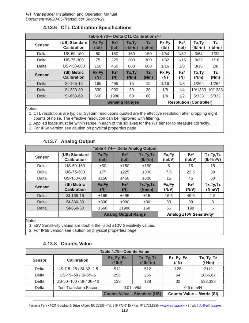
F/T Transducer Installation and Operation ManualDocument #9620-05-Transducer Section-21
Pinnacle Park • 1031 Goodworth Drive • Apex, NC 27539 • Tel: 919.772.0115 • Fax: 919.772.8259 • www.ati-ia.com • Email: [email protected] 118
4.13.6 CTLCalibrationSpecifications
Table 4.73— Delta CTL Calibrations1, 2
Sensor (US)Standard Calibration
Fx,Fy (lbf)
Fz3 (lbf)
Tx,Ty (lbf-in)
Tz (lbf-in)
Fx,Fy (lbf)
Fz3 (lbf)
Tx,Ty (lbf-in)
Tz (lbf-in)
Delta US-50-150 50 150 150 150 1/64 1/32 3/64 1/32Delta US-75-300 75 225 300 300 1/32 1/16 3/32 1/16Delta US-150-600 150 450 600 600 1/16 1/8 3/16 1/8
Sensor (SI)Metric Calibration
Fx,Fy (N)
Fz3 (N)
Tx,Ty (Nm)
Tz (Nm)
Fx,Fy (N)
Fz3 (N)
Tx,Ty (Nm)
Tz (Nm)
Delta SI-165-15 165 495 15 15 1/16 1/8 1/264 1/264Delta SI-330-30 330 990 30 30 1/8 1/4 10/1333 10/1333Delta SI-660-60 660 1980 60 60 1/4 1/2 5/333 5/333
Sensing Ranges Resolution(Controller)Notes: 1. CTL resolutions are typical. System resolutions quoted are the effective resolution after dropping eight countsofnoise.Theeffectiveresolutioncanbeimprovedwithfiltering. 2. Applied loads must be within range in each of the six axes for the F/T sensor to measure correctly. 3. For IP68 version see caution on physical properties page.
4.13.7 Analog OutputTable 4.74— Delta Analog Output
Sensor (US)Standard Calibration
Fx,Fy (lbf)
Fz2 (lbf)
Tx,Ty,Tz (lbf-in)
Fx,Fy (lbf/V)
Fz2 (lbf/V)
Tx,Ty,Tz (lbf-in/V)
Delta US-50-150 ±50 ±150 ±150 5 15 15Delta US-75-300 ±75 ±225 ±300 7.5 22.5 30Delta US-150-600 ±150 ±450 ±600 15 45 60
Sensor (SI)Metric Calibration
Fx,Fy (N)
Fz2 (N)
Tx,Ty,Tz (Nmm)
Fx,Fy (N/V)
Fz2 (N/V)
Tx,Ty,Tz (Nm/V)
Delta SI-165-15 ±165 ±495 ±15 16.5 49.5 1.5Delta SI-330-30 ±330 ±990 ±30 33 99 3Delta SI-660-60 ±660 ±1980 ±60 66 198 6
Analog Output Range Analog±10VSensitivity1
Notes: 1. ±5V Sensitivity values are double the listed ±10V Sensitivity values. 2. For IP68 version see caution on physical properties page.
4.13.8 CountsValueTable 4.75—CountsValue
Sensor Calibration Fx,Fy,Fz (/lbf)
Tx,Ty,Tz (/lbf-in)
Fx,Fy,Fz (/N)
Tx,Ty,Tz (/Nm)
Delta US-7.5–25/SI-32–2.5 512 512 128 2112Delta US-15–50/SI-65–5 256 256 64 1066.67Delta US-30–100/SI-130–10 128 128 32 533.333Delta Tool Transform Factor 0.01 in/lbf 0.6 mm/N
CountsValue–Standard(US) CountsValue–Metric(SI)

F/T Transducer Installation and Operation ManualDocument #9620-05-Transducer Section-21
Pinnacle Park • 1031 Goodworth Drive • Apex, NC 27539 • Tel: 919.772.0115 • Fax: 919.772.8259 • www.ati-ia.com • Email: [email protected] 119
4.13.9 Delta(USCalibrationComplexLoading)(IncludesIP60/IP65/IP68)1
HelpDelta
US-50-150 US-75-300 US-150-600
Note: 1. For IP68 version see caution on physical properties page.
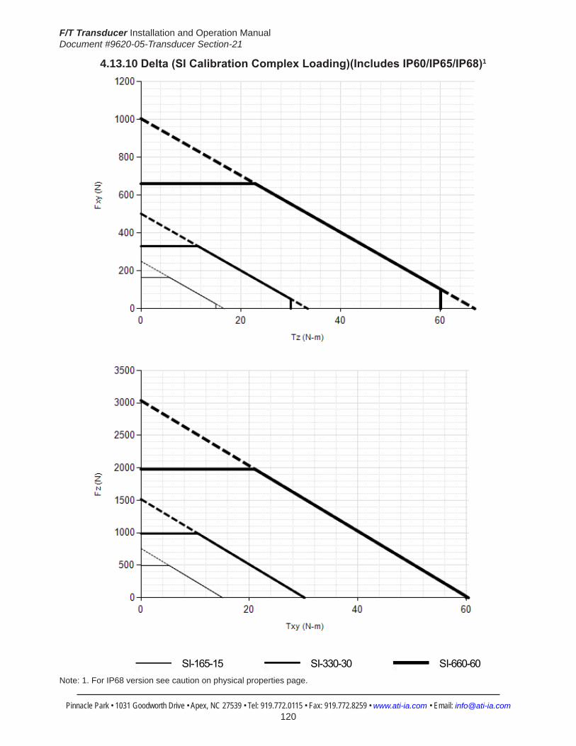
F/T Transducer Installation and Operation ManualDocument #9620-05-Transducer Section-21
Pinnacle Park • 1031 Goodworth Drive • Apex, NC 27539 • Tel: 919.772.0115 • Fax: 919.772.8259 • www.ati-ia.com • Email: [email protected] 120
4.13.10 Delta(SICalibrationComplexLoading)(IncludesIP60/IP65/IP68)1
HelpDelta
SI-165-15 SI-330-30 SI-660-60
Note: 1. For IP68 version see caution on physical properties page.

F/T Transducer Installation and Operation ManualDocument #9620-05-Transducer Section-21
Pinnacle Park • 1031 Goodworth Drive • Apex, NC 27539 • Tel: 919.772.0115 • Fax: 919.772.8259 • www.ati-ia.com • Email: [email protected] 121
4.13.11 DeltaDAQ/NetTransducerDrawing
3rd
AN
GLE
PRO
JEC
TION
63.5
DAQ
Sys
tem
25.4
DAQ
Sys
tem
66.9
Net
Sys
tem
32.8
Net
Sys
tem
30°
Cus
tom
er m
achi
nes
mou
ntin
g pa
ttern
as
need
ed in
pla
te.
Rem
ove
plat
e pr
ior t
o m
achi
ning
.+X -X
-Y+Y
MO
UN
TIN
G S
IDE
Con
nect
or fo
r Cab
le
Varie
s D
epen
ding
on
Sens
or S
elec
ted
1.2
1
9.1
94
.5
73
92
28
28.
6
33.
3
+Z-Z
Tool
Ada
pter
Plat
e
Sens
ing
Ref
eren
ce
Fram
e O
rigin
Cus
tom
er In
terfa
ce16
H7
3.6
6 Sl
ip F
it 5.
6C
usto
mer
Inte
rface
(See
Not
e 3)
25±
0.02
5
4X T
ap M
6X1.
0
5.6
Equa
lly S
pace
dC
usto
mer
Inte
rface
(See
Not
e 3) B
.C.
50
+X -X
-Y+YSe
nsin
g R
efer
ence
Fr
ame
Orig
in
TOO
L SI
DE
ISO
MET
RIC
VIE
W
Not
es: Mat
eria
l: H
arde
ned
Stai
nles
s St
eel a
nd A
lum
inum
.1.
Do
not t
ouch
inte
rnal
ele
ctro
nics
or i
nstru
men
tatio
n.2.
This
cou
ld d
amag
e th
e tra
nsdu
cer a
nd w
ill vo
id th
e w
arra
nty.
DO
NO
T EX
CEE
D IN
TER
FAC
E D
EPTH
, MA
Y C
AU
SE D
AM
AG
E.3.
For b
est a
ccur
acy,
tran
sduc
er m
ust b
e m
ount
ed to
a s
urfa
ce ri
gid
4.
eno
ugh
to s
uppo
rt lo
ads
with
out d
efle
ctio
n.
SID
E VI
EW
Mou
ntin
g Ad
apte
rPl
ate
Rev.
Des
crip
tion
Initi
ator
Dat
e
04EC
O 1
2940
; Add
ed 6
mm
to "
Slip
Fit
5.6
Cus
tom
er
Inte
rface
(See
Not
e 3)
" cal
lout
; Add
ed d
iam
eter
sym
bol t
o 92
dim
ensio
n; R
emov
ed 1
.0 x
45
from
16
H7
3.6
.TB
C6/
1/20
15
B1:
11
1RE
VISIO
N
NO
TES:
UN
LESS
OTH
ERW
ISE
SPEC
IFIED
.
DO
NO
T SC
ALE
DRA
WIN
G.
ALL
DIM
ENSI
ON
S A
RE IN
M
ILLIM
ETER
S.
DRA
WN
BY:
CHE
CKE
D B
Y:
R. C
ham
bers
11/
6/08
P. F
usco
12/
5/08
TITLE SC
ALE
SIZE
DRA
WIN
G N
UMBE
R
PRO
JEC
T #SH
EET
O
F 92
30-0
5-13
3004
PRO
PERT
Y O
F A
TI IN
DUS
TRIA
L A
UTO
MA
TION
, IN
C. N
OT T
O B
E RE
PRO
DUC
ED IN
AN
Y M
AN
NER
EXC
EPT O
N O
RDER
OR
WITH
PRI
OR
WRI
TTEN
AUT
HORI
ZATIO
N O
F A
TI.
1031
Goo
dwor
th Dr
ive, A
pex,
NC 27
539,
USA
Tel: +
1.919
.772.0
115
Em
ail: in
fo@ati
-ia.co
mFa
x: +1
.919.7
72.82
59
www
.ati-ia
.com
ISO
9001
Reg
ister
ed C
ompa
ny
Del
ta T
rans
duce
r

F/T Transducer Installation and Operation ManualDocument #9620-05-Transducer Section-21
Pinnacle Park • 1031 Goodworth Drive • Apex, NC 27539 • Tel: 919.772.0115 • Fax: 919.772.8259 • www.ati-ia.com • Email: [email protected] 122
4.13.12 9105-T-Delta Transducer without Mounting Adapter Drawing
3rd
AN
GLE
PRO
JEC
TION
29.5
18.5
3.8
41.5
00±0
.025 74
H7
1.3
Cha
mfe
r .63
x 4
5C
usto
mer
Inte
rface
(See
Not
e 4)
Cus
tom
er In
terfa
ceEq
ually
Spa
ced
6X T
ap M
5X0.
8 8
83 B
.C.
+X
-Y
-X
+Y
Rig
ht-A
ngle
Con
nect
or
MO
UN
TIN
G S
IDE
5 D
owel
Pin
EXPO
SED
CIR
CUI
TRY
IN TH
IS A
REA
DO
NO
T TO
UCH
73
4.7
Max
92
2828.6
Tool
Ada
pter
Pla
te
+Z-Z
SID
E VI
EW
Sens
ing
Ref
eren
ceFr
ame
Orig
in6
Slip
Fit
5.6
Cus
tom
er In
terfa
ce(S
ee N
ote
4)
16 H
7 3
.6C
ham
fer 1
.0 x
45
Cus
tom
er In
terfa
ce25
±0.0
25
(See
Not
e 4)
4X T
ap M
6X1.
0 5.
6Eq
ually
Spa
ced
Cus
tom
er In
terfa
ce
45°
50 B
.C.
TOO
L SI
DE
+X
-Y+Y
-XSe
nsin
g R
efer
ence
Fram
e O
rigin
ISO
MET
RIC
VIE
W
Not
es:
1. M
ater
ial:
Har
dene
d St
ainl
ess
Stee
l.2.
Do
not t
ouch
inte
rnal
ele
ctro
nics
or i
nstru
men
tatio
n. T
his
coul
d
dam
age
trans
duce
r and
will
void
war
rant
y.3.
Too
l Sid
e R
ING
-PLU
G O
ptio
n M
oves
Orig
in. S
ee
923
0-05
-105
9 fo
r Pos
ition
.4.
DO
NO
T EX
CEED
INTE
RFAC
E DE
PTH,
MAY
CAU
SE D
AMAG
E.5.
For
bes
t acc
urac
y, tr
ansd
ucer
mus
t be
mou
nted
to a
sur
face
rigi
d
eno
ugh
to s
uppo
rt lo
ads
with
out d
efle
ctio
n.
Rev.
Des
crip
tion
Initi
ator
Dat
e
06EC
O 9
037:
Del
ete
over
load
pin
sJW
10/1
1/20
11
B1:
11
1RE
VISIO
N
NO
TES:
UN
LESS
OTH
ERW
ISE
SPEC
IFIED
.
DO
NO
T SC
ALE
DRA
WIN
G.
ALL
DIM
ENSI
ON
S A
RE IN
M
ILLIM
ETER
S.
DRA
WN
BY:
CHE
CKE
D B
Y:
C. S
turg
is 0
1/28
/10
P. F
usco
01/
28/1
0
TITLE SC
ALE
SIZE
DRA
WIN
G N
UMBE
R
PRO
JEC
T #SH
EET
O
F 92
30-0
5-11
02-
06
PRO
PERT
Y O
F A
TI IN
DUS
TRIA
L A
UTO
MA
TION
, IN
C. N
OT T
O B
E RE
PRO
DUC
ED IN
AN
Y M
AN
NER
EXC
EPT O
N O
RDER
OR
WITH
PRI
OR
WRI
TTEN
AUT
HORI
ZATIO
N O
F A
TI.
1031
Goo
dwor
th Dr
ive, A
pex,
NC 27
539,
USA
Tel: +
1.919
.772.0
115
Em
ail: in
fo@ati
-ia.co
mFa
x: +1
.919.7
72.82
59
www
.ati-ia
.com
ISO
9001
Reg
ister
ed C
ompa
ny
Del
ta T
rans
duce
r with
out M
ount
ing
Adap
ter
Note: Mux transducers are used in F/T Controller systems.

F/T Transducer Installation and Operation ManualDocument #9620-05-Transducer Section-21
Pinnacle Park • 1031 Goodworth Drive • Apex, NC 27539 • Tel: 919.772.0115 • Fax: 919.772.8259 • www.ati-ia.com • Email: [email protected] 123
4.13.13 Delta Mounting Adapter Drawing
3rd
AN
GLE
PRO
JEC
TION
6X C
ount
ersi
nk h
oles
for
M5
SFH
CS
Slip
Fit
for
5 D
owel
Pin
74 R
efBo
ss
94.5
4.7
1.3
M5
x 10
SFH
CS,
Gra
de 1
0.9
M5
x 10
,D
owel
Pin
Del
ta M
ount
ing
Adap
ter
Del
ta T
rans
duce
rTr
ansd
ucer
with
Mou
ntin
g Ad
apte
r
ISO
MET
RIC
VIE
WSC
ALE
2:3
Not
es: Mat
eria
l: H
igh-
Tens
ile A
lum
inum
1.Fi
nish
: Sof
t Bla
ck A
nodi
ze2.
Mou
ntin
g Ad
apte
r: C
usto
mer
to m
achi
ne p
late
as
requ
ired
for m
ount
ing.
3.Su
pplie
d w
ith (6
) M5
x 10
SFH
CS,
Gra
de 1
0.9
and
(1) M
5 x
10 D
owel
Pin
, D
IN 6
325.
74
Bos
s an
d 5
Dow
el P
in u
sed
for l
ocat
ing
to D
elta
Tra
nsdu
cer.
C L
Rev.
Des
crip
tion
Initi
ator
Dat
e
05Ec
o 10
296;
Upd
ated
Tran
sduc
er B
ody
with
out o
verlo
ad p
ins.
CF
10/2
6/20
12
B1:
11
1RE
VISIO
N
NO
TES:
UN
LESS
OTH
ERW
ISE
SPEC
IFIED
.
DO
NO
T SC
ALE
DRA
WIN
G.
ALL
DIM
ENSI
ON
S A
RE IN
M
ILLIM
ETER
S.
DRA
WN
BY:
CHE
CKE
D B
Y:
C. F
leso
ck, 6
/19/
2009
P. F
usco
, 6/2
2/20
09
TITLE SC
ALE
SIZE
DRA
WIN
G N
UMBE
R
PRO
JEC
T #SH
EET
O
F 92
30-0
5-10
6305
PRO
PERT
Y O
F A
TI IN
DUS
TRIA
L A
UTO
MA
TION
, IN
C. N
OT T
O B
E RE
PRO
DUC
ED IN
AN
Y M
AN
NER
EXC
EPT O
N O
RDER
OR
WITH
PRI
OR
WRI
TTEN
AUT
HORI
ZATIO
N O
F A
TI.
1031
Goo
dwor
th Dr
ive, A
pex,
NC 27
539,
USA
Tel: +
1.919
.772.0
115
Em
ail: in
fo@ati
-ia.co
mFa
x: +1
.919.7
72.82
59
www
.ati-ia
.com
ISO
9001
Reg
ister
ed C
ompa
ny
Del
ta M
ount
ing
Adap
ter

F/T Transducer Installation and Operation ManualDocument #9620-05-Transducer Section-21
Pinnacle Park • 1031 Goodworth Drive • Apex, NC 27539 • Tel: 919.772.0115 • Fax: 919.772.8259 • www.ati-ia.com • Email: [email protected] 124
4.13.14 Delta IP60 Transducer Drawing
3rd
AN
GLE
PRO
JEC
TION
B.C
. 63
84.7
2X
6 Sl
ip F
it 6.
35C
usto
mer
Inte
rface
120°
117
45°
31.5
00±0
.025
47.2
50±0
.025
27.2
80±0
.025
B.C
. 10
6.7
45°
Side
Pat
tern
Opt
iona
l Mou
ntin
g C
usto
mer
Inte
rface
Equa
lly S
pace
dFo
r M6
SHC
S4X
6
.7 T
hru
58.4
MU
X &
DAQ
Syst
em
67.2
Net
Sys
tem
Not
es:
1. M
ater
ial:
Stai
nles
s St
eel a
nd A
lum
inum
2. S
ensi
ng R
efer
ence
Fra
me
Orig
in a
t Sur
face
Cen
ter o
f Too
l Ada
pter
.3.
Do
not d
isas
sem
ble
trans
duce
r. D
oing
so
coul
d da
mag
e tra
nsdu
cer
a
nd w
ill vo
id w
arra
nty.
4. F
or b
est a
ccur
acy,
tran
sduc
er m
ust b
e m
ount
ed to
a s
urfa
ce ri
gid
e
noug
h to
sup
port
load
s w
ithou
t def
lect
ion.
4X T
ap M
6 X
1.0
7.6
Equa
lly S
pace
dC
usto
mer
Inte
rface
+X
-Y+Y
-X
-Z
MO
UN
TIN
G S
IDE
+Y-Y
+X -X
Con
nect
or F
or C
able
Varie
s D
epen
ding
on
Sens
or S
elec
ted
45.2
11.4
47.
1 M
ount
ing
Adap
ter P
late
Sens
ing
Ref
eren
ceFr
ame
Orig
in
Neo
pren
eR
ubbe
r D
ust J
acke
t
SID
E VI
EW
+Z
Tool
Ada
pter
Plat
e
94.6
6 Sl
ip F
it10
Cus
tom
er In
terfa
ce
25±
0.02
5
4X T
ap M
6X1.
010
Equa
lly S
pace
dC
usto
mer
Inte
rface
16 H
7,
6C
ham
fer 1
.0X4
5C
usto
mer
Inte
rface
B.C
. 50
Se
nsin
g R
efer
ence
Fram
e O
rigin TO
OL
SID
E
ISO
MET
RIC
VIE
W
Rev.
Des
crip
tion
Initi
ator
Dat
e
06Ec
o 16
391;
Dim
47.
1 w
as 4
6.7
(ass
embl
y m
ate
issue
).LJ
H3/
11/2
014
B1:
11
1RE
VISIO
N
NO
TES:
UN
LESS
OTH
ERW
ISE
SPEC
IFIED
.
DO
NO
T SC
ALE
DRA
WIN
G.
ALL
DIM
ENSI
ON
S A
RE IN
M
ILLIM
ETER
S.
DRA
WN
BY:
CHE
CKE
D B
Y:
P.Sp
arro
w, 2
/13/
06
-
TITLE SC
ALE
SIZE
DRA
WIN
G N
UMBE
R
PRO
JEC
T #SH
EET
O
F 92
30-0
5-12
6206
PRO
PERT
Y O
F A
TI IN
DUS
TRIA
L A
UTO
MA
TION
, IN
C. N
OT T
O B
E RE
PRO
DUC
ED IN
AN
Y M
AN
NER
EXC
EPT O
N O
RDER
OR
WITH
PRI
OR
WRI
TTEN
AUT
HORI
ZATIO
N O
F A
TI.
1031
Goo
dwor
th Dr
ive, A
pex,
NC 27
539,
USA
Tel: +
1.919
.772.0
115
Em
ail: in
fo@ati
-ia.co
mFa
x: +1
.919.7
72.82
59
www
.ati-ia
.com
ISO
9001
Reg
ister
ed C
ompa
ny
IP60
Del
ta T
rans
duce
r

F/T Transducer Installation and Operation ManualDocument #9620-05-Transducer Section-21
Pinnacle Park • 1031 Goodworth Drive • Apex, NC 27539 • Tel: 919.772.0115 • Fax: 919.772.8259 • www.ati-ia.com • Email: [email protected] 125
4.13.15 ECAT Delta IP60 Transducer Drawing
3rd
AN
GLE
PRO
JEC
TION
4X
6.7
Thr
uFo
r M6
SH
CS
Equ
ally
Spa
ced
Cus
tom
er In
terfa
ceO
ptio
nal M
ount
ing
Sid
e P
atte
rn
4X T
ap M
6 9
.2E
qual
ly S
pace
dC
usto
mer
Inte
rface
2X
6 S
lip F
it6
Cus
tom
er In
terfa
ce
72.
1
84.
7
31.
500±
0.02
5
27.
280±
0.02
5
47.
250±
0.02
5
11
6.8
B.C
.10
6.7
B.C
.63
45°
1
20°
11.
4 3
5.7
47.
1
45.
2 1
.9
92
Sen
sing
Ref
eren
ceFr
ame
Orig
in
Eth
erC
AT
LED
Indi
cato
rs
Mou
ntin
gA
dapt
erP
late
Rin
g Te
rmin
al(F
or O
ptio
nal
Ear
th G
roun
d C
onne
ctio
n)
Tool
Ada
pter
Pla
te
6
Slip
Fit
6C
usto
mer
Inte
rface
16 H
7 5.
8C
ham
fer 1
.0 X
45
Cus
tom
er In
terfa
ce
94
.6
4X T
ap M
6X1.
0 9
.8E
qual
ly S
pace
dC
usto
mer
Inte
rface
B.C
. 50
45°
Sen
sing
Ref
eren
ceFr
ame
Orig
in
Eth
erC
AT
(Opt
iona
l PoE
)
DC
Pow
er
Not
es:
Mat
eria
l: S
tain
less
Ste
el a
nd A
lum
inum
1.S
ensi
ng R
efer
ence
Fra
me
Orig
in a
t sur
face
cen
ter o
f Too
l Ada
pter
.2.
Do
not d
isas
sem
ble
trans
duce
r. D
oing
so
coul
d da
mag
e tra
nsdu
cer a
nd w
ill v
oid
war
rant
y.3.
For b
est a
ccur
acy,
tran
sduc
er m
ust b
e m
ount
ed to
a s
urfa
ce ri
gid
enou
gh to
sup
port
load
s 4.
with
out d
efle
ctio
n.
-Z+Z
TOO
L S
IDE
SID
E V
IEW
MO
UN
TIN
G S
IDE
+Y-Y
+X
-X
+X
-X
-Y+Y
Rev.
Des
crip
tion
Initi
ator
Dat
e
01In
itial
Rel
ease
RTD
12/5
/201
6
B1:
21
2RE
VISI
ON
NO
TES:
UN
LESS
OTH
ERW
ISE
SPEC
IFIE
D.
DO
NO
T SC
ALE
DRA
WIN
G.
ALL
DIM
ENSI
ON
S A
RE IN
M
ILLIM
ETER
S.
DRA
WN
BY:
CHE
CKE
D B
Y:
R.D
upre
e 12
/2/1
6
A.G
lusi
ec 1
2/5/
16
TITLE SC
ALE
SIZE
DRA
WIN
G N
UMBE
R
PRO
JEC
T #
SHEE
T
O
F 92
30-0
5-15
1015
0121
-101
PRO
PERT
Y O
F A
TI IN
DUS
TRIA
L A
UTO
MA
TION
, IN
C. N
OT
TO B
E RE
PRO
DUC
ED IN
AN
Y M
AN
NER
EXC
EPT
ON
ORD
ER O
R W
ITH P
RIO
R W
RITT
EN A
UTHO
RIZA
TION
OF
ATI.
1031
Goo
dwor
th Dr
ive, A
pex,
NC 27
539,
USA
Tel: +
1.919
.772.0
115
Em
ail: in
fo@ati
-ia.co
mFa
x: +1
.919.7
72.82
59
www
.ati-ia
.com
ISO
9001
Reg
ister
ed C
ompa
ny
IP60
Del
taTr
ansd
ucer
with
Eth
erC
AT E
lect
roni
cs
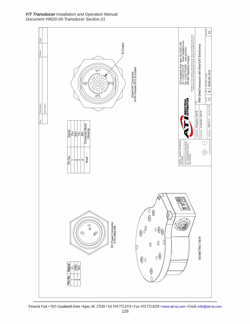
F/T Transducer Installation and Operation ManualDocument #9620-05-Transducer Section-21
Pinnacle Park • 1031 Goodworth Drive • Apex, NC 27539 • Tel: 919.772.0115 • Fax: 919.772.8259 • www.ati-ia.com • Email: [email protected] 126
3rd
AN
GLE
PRO
JEC
TION
ISO
ME
TRIC
VIE
W
DC
Pow
er C
onne
ctor
3-P
in M
ale
M8
D-C
oded
Eth
erC
AT
Con
nect
or4-
Pin
Fem
ale
M12
D-C
oded
Pin
No.
Sign
al1
V+
3G
ND
4N
/C
Pin
No.
Sig
nal
1TX
+2
RX
+3
TX-
4R
X-
She
llC
onne
ctor
Blo
ck
Hou
sing
Rev.
Des
crip
tion
Initi
ator
Dat
e
-Se
e Sh
eet1
--
B1:
22
2RE
VISI
ON
NO
TES:
UN
LESS
OTH
ERW
ISE
SPEC
IFIE
D.
DO
NO
T SC
ALE
DRA
WIN
G.
ALL
DIM
ENSI
ON
S A
RE IN
M
ILLIM
ETER
S.
DRA
WN
BY:
CHE
CKE
D B
Y:
R.D
upre
e 12
/2/1
6
A.G
lusi
ec 1
2/5/
16
TITLE SC
ALE
SIZE
DRA
WIN
G N
UMBE
R
PRO
JEC
T #
SHEE
T
O
F 92
30-0
5-15
1015
0121
-101
PRO
PERT
Y O
F A
TI IN
DUS
TRIA
L A
UTO
MA
TION
, IN
C. N
OT
TO B
E RE
PRO
DUC
ED IN
AN
Y M
AN
NER
EXC
EPT
ON
ORD
ER O
R W
ITH P
RIO
R W
RITT
EN A
UTHO
RIZA
TION
OF
ATI.
1031
Goo
dwor
th Dr
ive, A
pex,
NC 27
539,
USA
Tel: +
1.919
.772.0
115
Em
ail: in
fo@ati
-ia.co
mFa
x: +1
.919.7
72.82
59
www
.ati-ia
.com
ISO
9001
Reg
ister
ed C
ompa
ny
IP60
Del
taTr
ansd
ucer
with
Eth
erC
AT E
lect
roni
cs

F/T Transducer Installation and Operation ManualDocument #9620-05-Transducer Section-21
Pinnacle Park • 1031 Goodworth Drive • Apex, NC 27539 • Tel: 919.772.0115 • Fax: 919.772.8259 • www.ati-ia.com • Email: [email protected] 127
4.13.16 Delta IP65 Transducer Drawing
3rd
AN
GLE
PRO
JEC
TION
63.3
Mux
& D
AQ
Syst
em
91.2
Mux
& D
AQSy
stem
28.
750±
0.02
5
84.
290±
0.02
5
49.
796±
0.02
5
64.
678±
0.02
5
2X
6 Sl
ip F
it Th
ruC
usto
mer
Inte
rface
4X6.
8 Th
ruFo
r M6
SHC
SEq
ually
Spa
ced
Cus
tom
er In
terfa
ceO
ptio
nal M
ount
ing
Side
Pat
tern
B.C
.11
5
B.C
.63
4X T
ap M
6X1.
0 7
.6Eq
ually
Spa
ced
Cus
tom
er In
terfa
ce
15.
750±
0.02
5
27.
280±
0.02
5
2X6
Slip
Fit
6.35
Cus
tom
er In
terfa
ce
47.
250±
0.02
5
70.5
N
et S
yste
m
84.2
Net
Sys
tem
45°
M
embr
ane
Vent
Con
nect
or F
or C
able
Varie
s D
epen
ding
on
Sens
or S
elec
ted
- X+ X
- Y+
Y
MO
UN
TIN
G S
IDE
6.7
52.
2
44.
5
Sens
ing
Ref
eren
ceFr
ame
Orig
in
Mou
ntin
g Ad
apte
rPl
ate
Tool
Ada
pter
Pl
ate
-Z+Z
SID
E VI
EW
10
3.6
12
6
45°
4X T
ap M
6X1.
0 8
.5Eq
ually
Spa
ced
Cus
tom
er In
terfa
ce
16 H
7 6.
35C
ham
fer 1
x 4
5C
usto
mer
Inte
rface
B.C
.50
25±
0.02
5
Sens
ing
Ref
eren
ceFr
ame
Orig
in
+ Y
- Y
TOO
L SI
DE
+ X - X
6 Sl
ip F
it 6.
35C
usto
mer
Inte
rface
ISO
MET
RIC
VIE
W
Not
es: M
ater
ial:
Stai
nles
s St
eel a
nd A
lum
inum
1.Se
nsin
g R
efer
ence
Fra
me
Orig
in a
t Sur
face
Cen
ter o
f Too
l Ada
pter
.2.
Do
not d
isas
sem
ble
trans
duce
r. D
oing
so
coul
d da
mag
e tra
nsdu
cer
3.an
d w
ill vo
id w
arra
nty.
For b
est a
ccur
acy,
tran
sduc
er m
ust b
e m
ount
ed to
a s
urfa
ce ri
gid
4.en
ough
to s
uppo
rt lo
ads
with
out d
efle
ctio
n.
Cab
le m
ust b
e co
nnec
ted
to tr
ansd
ucer
to m
aint
ain
prop
er s
eal.
5.C
able
is IP
65 ra
ted
only
at t
rans
duce
r end
.6.
Rev.
Des
crip
tion
Initi
ator
Dat
e
04EC
9399
: Cha
nged
to fl
ange
d M
AP
RKC
1/23
/201
2
05Ec
o 10
139;
Add
ed D
owel
cal
lout
to TA
P sid
e.LJ
H9/
13/2
012
B4:
51
1RE
VISIO
N
NO
TES:
UN
LESS
OTH
ERW
ISE
SPEC
IFIED
.
DO
NO
T SC
ALE
DRA
WIN
G.
ALL
DIM
ENSI
ON
S A
RE IN
M
ILLIM
ETER
S.
DRA
WN
BY:
CHE
CKE
D B
Y:
P.Sp
arro
w, 2
/16/
06
D. N
orto
n, 2
/17/
06
TITLE SC
ALE
SIZE
DRA
WIN
G N
UMBE
R
PRO
JEC
T #SH
EET
O
F 92
30-0
5-12
6705
PRO
PERT
Y O
F A
TI IN
DUS
TRIA
L A
UTO
MA
TION
, IN
C. N
OT T
O B
E RE
PRO
DUC
ED IN
AN
Y M
AN
NER
EXC
EPT O
N O
RDER
OR
WITH
PRI
OR
WRI
TTEN
AUT
HORI
ZATIO
N O
F A
TI.
1031
Goo
dwor
th Dr
ive, A
pex,
NC 27
539,
USA
Tel: +
1.919
.772.0
115
Em
ail: in
fo@ati
-ia.co
mFa
x: +1
.919.7
72.82
59
www
.ati-ia
.com
ISO
9001
Reg
ister
ed C
ompa
ny
IP65
Del
ta T
rans
duce
r

F/T Transducer Installation and Operation ManualDocument #9620-05-Transducer Section-21
Pinnacle Park • 1031 Goodworth Drive • Apex, NC 27539 • Tel: 919.772.0115 • Fax: 919.772.8259 • www.ati-ia.com • Email: [email protected] 128
4.13.17 ECAT Delta IP65 Transducer Drawing
3rd
AN
GLE
PRO
JEC
TION
68.
5
4X T
ap M
6X1.
0 7
.6E
qual
ly S
pace
dC
usto
mer
Inte
rface
64.
678±
0.02
5 4
9.79
6±0.
025
27.
280±
0.02
5
2X
6 S
lip F
it 6
.35
Cus
tom
er In
terfa
ce
2X
6 S
lip F
it Th
ruC
usto
mer
Inte
rface
84.
2 4X
6
.8 T
hru
For M
6 S
HC
SE
qual
ly S
pace
dC
usto
mer
Inte
rface
Opt
iona
l Mou
ntin
gS
ide
Pat
tern
B.C
. 11
5
84.
290±
0.02
5
47.
250±
0.02
5
15.
750±
0.02
5
28.
750±
0.02
5
B.C
.63
45°
D
C P
ower
-X
+X
+Y-Y
Eth
erC
AT
(Opt
iona
l PoE
)
6.7
44.
5
52.
2
Tool
Ada
pter
Pla
te
Mou
ntin
g A
dapt
erP
late
Sen
sing
Ref
eren
ceFr
ame
Orig
in
Eth
erC
AT
LED
Indi
cato
rs
-Z+Z
Rin
g Te
rmin
al(F
or O
ptio
nal
Ear
th G
roun
d C
onne
ctio
n)
B.C
.50
6
Slip
Fit
6.3
5C
usto
mer
Inte
rface
25±
0.02
5
10
3.6
12
6
16 H
7 6.
3C
ham
fer 1
x 4
5C
usto
mer
Inte
rface
4X T
ap M
6X1.
0 8
.5E
qual
ly S
pace
dC
usto
mer
Inte
rface 4
5° M
embr
ane
Ven
t
Sen
sing
Ref
eren
ceFr
ame
Orig
in
+Y-Y
+X -X
Not
es:
Mat
eria
l: S
tain
less
Ste
el a
nd A
lum
inum
1.S
ensi
ng R
efer
ence
Fra
me
Orig
in a
t Sur
face
Cen
ter o
f Too
l Ada
pter
.2.
Do
not d
isas
sem
ble
trans
duce
r. D
oing
so
coul
d da
mag
e tra
nsdu
cer a
nd w
ill v
oid
war
rant
y.3.
For b
est a
ccur
acy,
tran
sduc
er m
ust b
e m
ount
ed to
a s
urfa
ce ri
gid
enou
gh to
sup
port
load
s 4.
with
out d
efle
ctio
n.C
able
s m
ust b
e co
nnec
ted
to tr
ansd
ucer
to m
aint
ain
prop
er s
eal.
5.
MO
UN
TIN
G S
IDE
SID
E V
IEW
TOO
L S
IDE
Rev.
Des
crip
tion
Initi
ator
Dat
e
01In
itial
Dra
win
gLC
S4/
16/2
015
B4:
51
2RE
VISI
ON
NO
TES:
UN
LESS
OTH
ERW
ISE
SPEC
IFIE
D.
DO
NO
T SC
ALE
DRA
WIN
G.
ALL
DIM
ENSI
ON
S A
RE IN
M
ILLIM
ETER
S.
DRA
WN
BY:
CHE
CKE
D B
Y:
L. S
trahl
er 4
/16/
15
P. F
usco
4/1
7/15
TITLE SC
ALE
SIZE
DRA
WIN
G N
UMBE
R
PRO
JEC
T #
SHEE
T
O
F 92
30-0
5-14
6914
0328
-501
PRO
PERT
Y O
F A
TI IN
DUS
TRIA
L A
UTO
MA
TION
, IN
C. N
OT
TO B
E RE
PRO
DUC
ED IN
AN
Y M
AN
NER
EXC
EPT
ON
ORD
ER O
R W
ITH P
RIO
R W
RITT
EN A
UTHO
RIZA
TION
OF
ATI.
1031
Goo
dwor
th Dr
ive, A
pex,
NC 27
539,
USA
Tel: +
1.919
.772.0
115
Em
ail: in
fo@ati
-ia.co
mFa
x: +1
.919.7
72.82
59
www
.ati-ia
.com
ISO
9001
Reg
ister
ed C
ompa
ny
A. S
trotz
er 4
/21/
15
9105
-EC
AT-D
elta
-IP65
Cus
tom
er D
raw
ing

F/T Transducer Installation and Operation ManualDocument #9620-05-Transducer Section-21
Pinnacle Park • 1031 Goodworth Drive • Apex, NC 27539 • Tel: 919.772.0115 • Fax: 919.772.8259 • www.ati-ia.com • Email: [email protected] 129
3rd
AN
GLE
PRO
JEC
TION
DC
Pow
er C
onne
ctor
3-P
in M
ale
M8
D-C
oded
ISO
ME
TRIC
VIE
W
Eth
erC
AT
Con
nect
or4-
Pin
Fem
ale
M12
D-C
oded
Pin
No.
Sig
nal
1V
+3
GN
D4
N/C
Pin
No.
Sig
nal
1TX
+2
RX
+3
TX-
4R
X-
She
llC
onne
ctor
Blo
ck H
ousi
ng
B4:
52
2RE
VISI
ON
NO
TES:
UN
LESS
OTH
ERW
ISE
SPEC
IFIE
D.
DO
NO
T SC
ALE
DRA
WIN
G.
ALL
DIM
ENSI
ON
S A
RE IN
M
ILLIM
ETER
S.
DRA
WN
BY:
CHE
CKE
D B
Y:
L. S
trahl
er 4
/16/
15
P. F
usco
4/1
7/15
TITLE SC
ALE
SIZE
DRA
WIN
G N
UMBE
R
PRO
JEC
T #
SHEE
T
O
F 92
30-0
5-14
6914
0328
-501
PRO
PERT
Y O
F A
TI IN
DUS
TRIA
L A
UTO
MA
TION
, IN
C. N
OT
TO B
E RE
PRO
DUC
ED IN
AN
Y M
AN
NER
EXC
EPT
ON
ORD
ER O
R W
ITH P
RIO
R W
RITT
EN A
UTHO
RIZA
TION
OF
ATI.
1031
Goo
dwor
th Dr
ive, A
pex,
NC 27
539,
USA
Tel: +
1.919
.772.0
115
Em
ail: in
fo@ati
-ia.co
mFa
x: +1
.919.7
72.82
59
www
.ati-ia
.com
ISO
9001
Reg
ister
ed C
ompa
ny
A. S
trotz
er 4
/21/
15
9105
-EC
AT-D
elta
-IP65
Cus
tom
er D
raw
ing

F/T Transducer Installation and Operation ManualDocument #9620-05-Transducer Section-21
Pinnacle Park • 1031 Goodworth Drive • Apex, NC 27539 • Tel: 919.772.0115 • Fax: 919.772.8259 • www.ati-ia.com • Email: [email protected] 130
4.13.18DeltaIP68TransducerDrawing
101.
60B.C
.63
(2)
6 H
7,
6.35
Cus
tom
er In
terfa
ce
91.2
120°
[ref]
31.5
00±0
.012
45°
Typ
47.2
50±0
.012
27.2
80±0
.012
Equa
lly S
pace
dC
usto
mer
Inte
rface
(4) T
AP M
6X1
7.6
2
61
Con
nect
or fo
r Cab
leVa
ries
Dep
endi
ng o
nSe
nsor
Sel
ecte
dN
OTE
S:
1. M
ATER
IAL:
Sta
inle
ss S
teel
2. S
ensi
ng R
efer
ence
fram
e or
igin
at
s
urfa
ce c
ente
r of t
ool a
dapt
er.
3. D
o no
t dis
asse
mbl
e tra
nsdu
cer.
Doi
ng s
o
cou
ld d
amag
e tra
nsdu
cer a
nd v
oid
war
rant
y.4.
For
bes
t acc
urac
y, tr
ansd
ucer
mus
t be
m
ount
ed to
sur
face
s rig
id e
noug
h to
sup
port
lo
ads
with
out d
efle
ctio
n.
5. C
able
mus
t be
conn
ecte
d to
Tra
nsdu
cer t
o
mai
ntai
n pr
oper
sea
l.6.
Cab
le is
onl
y IP
68 ra
ted
at T
rans
duce
r End
. Tr
ansd
ucer
is
IP68
rate
d in
fres
hwat
er e
nviro
nmen
t at a
dep
th o
f
up
to 1
0 m
eter
s.
52.2
44.2
6.41.
4
96.5Se
nsin
g R
efer
ence
Fram
e O
rigin
6 H
7,
6.35
Cus
tom
er In
terfa
ceEq
ually
Spa
ced
Cus
tom
er In
terfa
ce
(4) T
AP M
6X1
8.8
9
B.C
.50
16 H
7,
6.35
Cha
mfe
r 1 x
45
Cus
tom
er In
terfa
ce
25.0
000.
012
45°
Typ
Sens
ing
Ref
eren
ceFr
ame
Orig
in
MO
UN
TIN
G S
IDE
SID
E VI
EWTO
OL
SID
E
+X
+Y-Y
-X
-Z+Z
ISO
MET
RIC
VIE
W
+ X
+ Y
- Y
- X
Rev.
Des
crip
tion
Initi
ator
Dat
e
02Up
date
d m
odel
link.
PS3/
4/20
06
NO
TES:
UN
LESS
OTH
ERW
ISE
SPEC
IFIED
DO
NO
T SC
ALE
DRA
WIN
G.
DRA
WN
IN S
OLID
WO
RKS.
ALL
DIM
ENSI
ON
S A
RE IN
MILL
IMET
ERS.
3rd
AN
GLE
PRO
JEC
TION
DRA
WN
BY:
CHE
CKE
D B
Y:
WEI
GHT
LBS
:
ASS
EMBL
Y RE
F:
P.Sp
arro
w, 2
/16/
06
D.N
orto
n, 2
/17/
06
TITLE SC
ALE
SIZE
DRA
WIN
G N
UMBE
R
PRO
DUC
T REL
EASE
#D
ATE
:SH
EET
O
F
PRO
PERT
Y O
F A
TI IN
DUS
TRIA
L A
UTO
MA
TION
, IN
C.
NO
T TO
BE
REPR
OD
UCED
IN A
NY
MA
NN
ER E
XCEP
T ON
ORD
ER O
R W
ITH P
RIO
R W
RITT
EN A
UTHO
RIZA
TION
OF
ATI.
IP68
-10m
DEL
TA T
rans
duce
r
9230
-05-
1272
-02
B1:
11
1
5.8
1031
Goo
dwor
th Dr
ive, A
pex,
NC 27
539,
USA
Tel: +
1.919
.772.0
115
Em
ail: in
fo@ati
-ia.co
mFa
x: +1
.919.7
72.82
59
www
.ati-ia
.com
ISO
9001
Reg
ister
ed C
ompa
ny

F/T Transducer Installation and Operation ManualDocument #9620-05-Transducer Section-21
Pinnacle Park • 1031 Goodworth Drive • Apex, NC 27539 • Tel: 919.772.0115 • Fax: 919.772.8259 • www.ati-ia.com • Email: [email protected] 131
4.14 ThetaSpecifications(IncludesIP60/IP65/IP68Versions)4.14.1 Theta Physical Properties
Table 4.76—Theta Physical PropertiesSingle-Axis Overload (US)StandardUnits (SI)MetricUnitsFxy ±4500 lbf ±20000 NFz ±11000 lbf ±51000 NTxy ±18000 inf-lb ±2000 NmTz ±18000 inf-lb ±2000 NmStiffness(Calculated) X-axis&Y-axisforces(Kx,Ky) 4.0x10⁵ lb/in 7.1x10⁷ N/m Z-axisforce(Kz) 6.9x10⁵ lb/in 1.2x10⁸ N/m X-axis&Y-axistorque(Ktx,Kty) 3.0x10⁶ lbf-in/rad 3.4x10⁵ Nm/rad Z-axistorque(Ktz) 4.7x10⁶ lbf-in/rad 5.3x10⁵ Nm/rad Resonant Frequency Fx, Fy, Tz 680 Hz 680 HzFz, Tx, Ty 820 Hz 820 HzPhysicalSpecifications Weight1 11 lb 4.99 kgDiameter1 6.1 in 155 mmHeight1 2.41 in 61.1 mmNote: 1.Specificationsincludestandardinterfaceplates.
4.14.2 Theta IP60 Physical PropertiesTable 4.77—Theta IP60 Physical Properties
Single-Axis Overload (US)StandardUnits (SI)MetricUnitsFxy ±4500 lbf ±20000 NFz ±11000 lbf ±51000 NTxy ±18000 inf-lb ±2000 NmTz ±18000 inf-lb ±2000 NmStiffness(Calculated) X-axis&Y-axisforces(Kx,Ky) 4.0x10⁵ lb/in 7.1x10⁷ N/m Z-axisforce(Kz) 6.9x10⁵ lb/in 1.2x10⁸ N/m X-axis&Y-axistorque(Ktx,Kty) 3.0x10⁶ lbf-in/rad 3.4x10⁵ Nm/rad Z-axistorque(Ktz) 4.7x10⁶ lbf-in/rad 5.3x10⁵ Nm/rad Resonant Frequency Fx, Fy, Tz N/A N/AFz, Tx, Ty N/A N/APhysicalSpecifications Weight1 19 lb 8.62 kgDiameter1 7.63 in 194 mmHeight1 2.91 in 74 mmNote: 1.Specificationsincludestandardinterfaceplates.
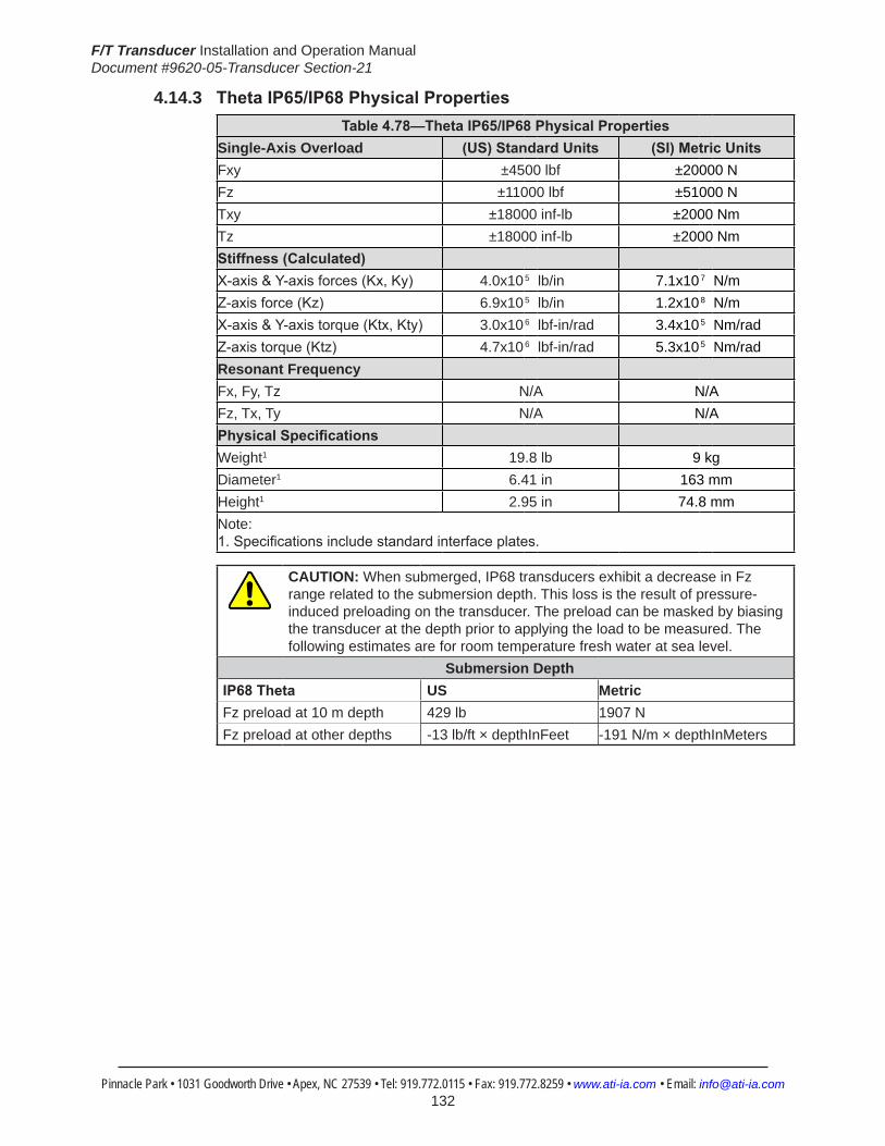
F/T Transducer Installation and Operation ManualDocument #9620-05-Transducer Section-21
Pinnacle Park • 1031 Goodworth Drive • Apex, NC 27539 • Tel: 919.772.0115 • Fax: 919.772.8259 • www.ati-ia.com • Email: [email protected] 132
4.14.3 ThetaIP65/IP68PhysicalPropertiesTable4.78—ThetaIP65/IP68PhysicalProperties
Single-Axis Overload (US)StandardUnits (SI)MetricUnitsFxy ±4500 lbf ±20000 NFz ±11000 lbf ±51000 NTxy ±18000 inf-lb ±2000 NmTz ±18000 inf-lb ±2000 NmStiffness(Calculated) X-axis&Y-axisforces(Kx,Ky) 4.0x10⁵ lb/in 7.1x10⁷ N/m Z-axisforce(Kz) 6.9x10⁵ lb/in 1.2x10⁸ N/m X-axis&Y-axistorque(Ktx,Kty) 3.0x10⁶ lbf-in/rad 3.4x10⁵ Nm/rad Z-axistorque(Ktz) 4.7x10⁶ lbf-in/rad 5.3x10⁵ Nm/rad Resonant Frequency Fx, Fy, Tz N/A N/AFz, Tx, Ty N/A N/APhysicalSpecifications Weight1 19.8 lb 9 kgDiameter1 6.41 in 163 mmHeight1 2.95 in 74.8 mmNote: 1.Specificationsincludestandardinterfaceplates.
CAUTION: When submerged, IP68 transducers exhibit a decrease in Fz range related to the submersion depth. This loss is the result of pressure-induced preloading on the transducer. The preload can be masked by biasing the transducer at the depth prior to applying the load to be measured. The following estimates are for room temperature fresh water at sea level.
Submersion DepthIP68Theta US MetricFz preload at 10 m depth 429 lb 1907 NFz preload at other depths -13 lb/ft × depthInFeet -191 N/m × depthInMeters
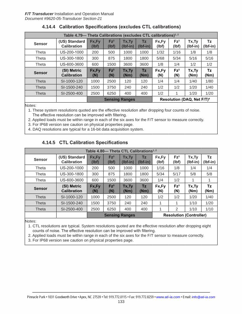
F/T Transducer Installation and Operation ManualDocument #9620-05-Transducer Section-21
Pinnacle Park • 1031 Goodworth Drive • Apex, NC 27539 • Tel: 919.772.0115 • Fax: 919.772.8259 • www.ati-ia.com • Email: [email protected] 133
4.14.4 CalibrationSpecifications(excludesCTLcalibrations)
Table 4.79—ThetaCalibrations(excludesCTLcalibrations)1, 2
Sensor (US)Standard Calibration
Fx,Fy (lbf)
Fz3 (lbf)
Tx,Ty (lbf-in)
Tz (lbf-in)
Fx,Fy (lbf)
Fz3 (lbf)
Tx,Ty (lbf-in)
Tz (lbf-in)
Theta US-200-1000 200 500 1000 1000 1/32 1/16 1/8 1/8Theta US-300-1800 300 875 1800 1800 5/68 5/34 5/16 5/16Theta US-600-3600 600 1500 3600 3600 1/8 1/4 1/2 1/2
Sensor (SI)Metric Calibration
Fx,Fy (N)
Fz3 (N)
Tx,Ty (Nm)
Tz (Nm)
Fx,Fy (N)
Fz3 (N)
Tx,Ty (Nm)
Tz (Nm)
Theta SI-1000-120 1000 2500 120 120 1/4 1/4 1/40 1/80Theta SI-1500-240 1500 3750 240 240 1/2 1/2 1/20 1/40Theta SI-2500-400 2500 6250 400 400 1/2 1 1/20 1/20
Sensing Ranges Resolution(DAQ,NetF/T)4
Notes: 1. These system resolutions quoted are the effective resolution after dropping four counts of noise. Theeffectiveresolutioncanbeimprovedwithfiltering. 2. Applied loads must be within range in each of the six axes for the F/T sensor to measure correctly. 3. For IP68 version see caution on physical properties page. 4. DAQ resolutions are typical for a 16-bit data acquisition system.
4.14.5 CTLCalibrationSpecifications
Table4.80— Theta CTL Calibrations1, 2
Sensor (US)Standard Calibration
Fx,Fy (lbf)
Fz3 (lbf)
Tx,Ty (lbf-in)
Tz (lbf-in)
Fx,Fy (lbf)
Fz3 (lbf)
Tx,Ty (lbf-in)
Tz (lbf-in)
Theta US-200-1000 200 500 1000 1000 1/16 1/8 1/4 1/4Theta US-300-1800 300 875 1800 1800 5/34 5/17 5/8 5/8Theta US-600-3600 600 1500 3600 3600 1/4 1/2 1 1
Sensor (SI)Metric Calibration
Fx,Fy (N)
Fz3 (N)
Tx,Ty (Nm)
Tz (Nm)
Fx,Fy (N)
Fz3 (N)
Tx,Ty (Nm)
Tz (Nm)
Theta SI-1000-120 1000 2500 120 120 1/2 1/2 1/20 1/40Theta SI-1500-240 1500 3750 240 240 1 1 1/10 1/20Theta SI-2500-400 2500 6250 400 400 1 2 1/10 1/10
Sensing Ranges Resolution(Controller)Notes: 1. CTL resolutions are typical. System resolutions quoted are the effective resolution after dropping eight countsofnoise.Theeffectiveresolutioncanbeimprovedwithfiltering. 2. Applied loads must be within range in each of the six axes for the F/T sensor to measure correctly. 3. For IP68 version see caution on physical properties page.

F/T Transducer Installation and Operation ManualDocument #9620-05-Transducer Section-21
Pinnacle Park • 1031 Goodworth Drive • Apex, NC 27539 • Tel: 919.772.0115 • Fax: 919.772.8259 • www.ati-ia.com • Email: [email protected] 134
4.14.6 Analog Output
Table4.81— Theta Analog Output
Sensor (US)Standard Calibration
Fx,Fy (lbf)
Fz2 (lbf)
Tx,Ty,Tz (lbf-in)
Fx,Fy (lbf/V)
Fz2 (lbf/V)
Tx,Ty,Tz (lbf-in/V)
Theta US-200-1000 ±200 ±500 ±1000 20 50 100Theta US-300-1800 ±300 ±875 ±1800 30 87.5 180Theta US-600-3600 ±600 ±1500 ±3600 60 150 360
Sensor (SI)Metric Calibration
Fx,Fy (N)
Fz2 (N)
Tx,Ty,Tz (Nmm)
Fx,Fy (N/V)
Fz2 (N/V)
Tx,Ty,Tz (Nm/V)
Theta SI-1000-120 ±1000 ±2500 ±120 100 250 12Theta SI-1500-240 ±1500 ±3750 ±240 150 375 24Theta SI-2500-400 ±2500 ±6250 ±400 250 625 40
Analog Output Range Analog±10VSensitivity1
Notes: 1. ±5V Sensitivity values are double the listed ±10V Sensitivity values. 2. For IP68 version see caution on physical properties page.
4.14.7 CountsValueTable4.82—CountsValue
Sensor Calibration Fx,Fy,Fz (/lbf)
Tx,Ty,Tz (/lbf-in)
Fx,Fy,Fz (/N)
Tx,Ty,Tz (/Nm)
Theta US-200–1000/SI-1000–120 128 64 32 320Theta US-300–1800/SI-1500–240 54.4 12.8 16 160Theta US-600–3600/SI-2500–400 32 16 16 80Theta Tool Transform Factor See Tool Transform Factor table
CountsValue–Standard(US) CountsValue–Metric(SI)
4.14.8 Tool Transform Factor
Table4.83—Tool Transform FactorSensor Calibration US(English) SI(Metric)Theta US-200–1000/SI-1000–120 0.02 in/lbf 1 mm/NTheta US-300–1800/SI-1500–240 0.0425 in/lbf 1 mm/NTheta US-600–3600/SI-2500–400 0.02 in/lbf 2 mm/N
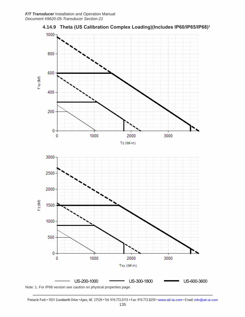
F/T Transducer Installation and Operation ManualDocument #9620-05-Transducer Section-21
Pinnacle Park • 1031 Goodworth Drive • Apex, NC 27539 • Tel: 919.772.0115 • Fax: 919.772.8259 • www.ati-ia.com • Email: [email protected] 135
4.14.9 Theta(USCalibrationComplexLoading)(IncludesIP60/IP65/IP68)1
HelpTheta
US-200-1000 US-300-1800 US-600-3600
Note: 1. For IP68 version see caution on physical properties page.

F/T Transducer Installation and Operation ManualDocument #9620-05-Transducer Section-21
Pinnacle Park • 1031 Goodworth Drive • Apex, NC 27539 • Tel: 919.772.0115 • Fax: 919.772.8259 • www.ati-ia.com • Email: [email protected] 136
4.14.10 Theta(SICalibrationComplexLoading)(IncludesIP60/IP65/IP68)1
HelpTheta
SI-1000-120 SI-1500-240 SI-2500-400
Note: 1. For IP68 version see caution on physical properties page.
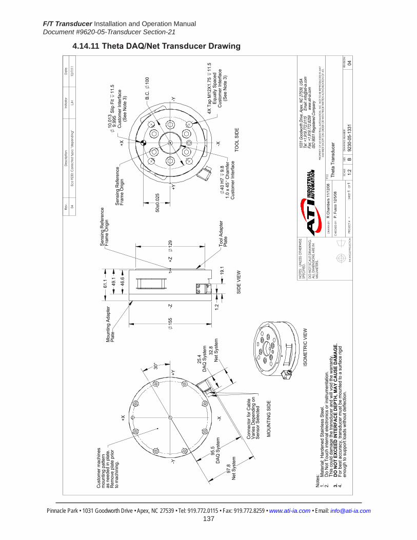
F/T Transducer Installation and Operation ManualDocument #9620-05-Transducer Section-21
Pinnacle Park • 1031 Goodworth Drive • Apex, NC 27539 • Tel: 919.772.0115 • Fax: 919.772.8259 • www.ati-ia.com • Email: [email protected] 137
4.14.11 ThetaDAQ/NetTransducerDrawing
3rd
AN
GLE
PRO
JEC
TION
95.5
DAQ
Sys
tem
25.4
DAQ
Sys
tem
97.8
Net
Sys
tem
32.8
Net
Sys
tem
30°
Cus
tom
er m
achi
nes
mou
ntin
g pa
ttern
as n
eede
d in
pla
te.
Rem
ove
plat
e pr
ior
to m
achi
ning
.
MO
UN
TIN
G S
IDE
+X -X
-Y+Y
49.1
1.2
1
9.1
46.
6
61.
1
15
5
129
Mou
ntin
g Ad
apte
r Pl
ate
Tool
Ada
pter
Pl
ate
Sens
ing
Ref
eren
ceFr
ame
Orig
in
SID
E VI
EW
+Z-Z
10.0
139.
995
Slip
Fit
11.5
Cus
tom
er In
terfa
ce(S
ee N
ote
3)
4X T
ap M
12X1
.75
11.5
Equa
lly S
pace
dC
usto
mer
Inte
rface
(See
Not
e 3)
40 H
7 9.
81.
0 x
45 C
ham
fer
Cus
tom
er In
terfa
ce
50±
0.02
5
B.C
. 10
0
Sens
ing
Ref
eren
ceFr
ame
Orig
in
TOO
L SI
DE
+Y-Y
+X -X
ISO
MET
RIC
VIE
W
Not
es: Mat
eria
l: H
arde
ned
Stai
nles
s St
eel.
1.D
o N
ot T
ouch
inte
rnal
ele
ctro
nics
or i
nstru
men
tatio
n.
2.Th
is c
ould
dam
age
the
trans
duce
r and
will
void
the
war
rant
y.D
O N
OT
EXC
EED
INTE
RFA
CE
DEP
TH, M
AY
CA
USE
DA
MA
GE.
3.Fo
r bes
t acc
urac
y, tr
ansd
ucer
mus
t be
mou
nted
to a
sur
face
rigi
d4.
e
noug
h to
sup
port
load
s w
ithou
t def
lect
ion.
Con
nect
or fo
r Cab
leVa
ries
Dep
endi
ng o
n Se
nsor
Sel
ecte
d
Rev.
Des
crip
tion
Initi
ator
Dat
e
04Ec
o 92
30; C
orre
cted
typo
; "de
pend
ing"
LJH
12/7
/11
B1:
21
1RE
VISIO
N
NO
TES:
UN
LESS
OTH
ERW
ISE
SPEC
IFIED
.
DO
NO
T SC
ALE
DRA
WIN
G.
ALL
DIM
ENSI
ON
S A
RE IN
M
ILLIM
ETER
S.
DRA
WN
BY:
CHE
CKE
D B
Y:
R C
ham
bers
11/
12/0
8
P. F
usco
12/
5/08
TITLE SC
ALE
SIZE
DRA
WIN
G N
UMBE
R
PRO
JEC
T #SH
EET
O
F 92
30-0
5-13
31-
04
PRO
PERT
Y O
F A
TI IN
DUS
TRIA
L A
UTO
MA
TION
, IN
C. N
OT T
O B
E RE
PRO
DUC
ED IN
AN
Y M
AN
NER
EXC
EPT O
N O
RDER
OR
WITH
PRI
OR
WRI
TTEN
AUT
HORI
ZATIO
N O
F A
TI.
1031
Goo
dwor
th Dr
ive, A
pex,
NC 27
539,
USA
Tel: +
1.919
.772.0
115
Em
ail: in
fo@ati
-ia.co
mFa
x: +1
.919.7
72.82
59
www
.ati-ia
.com
ISO
9001
Reg
ister
ed C
ompa
ny
Thet
a Tr
ansd
ucer

F/T Transducer Installation and Operation ManualDocument #9620-05-Transducer Section-21
Pinnacle Park • 1031 Goodworth Drive • Apex, NC 27539 • Tel: 919.772.0115 • Fax: 919.772.8259 • www.ati-ia.com • Email: [email protected] 138
4.14.12 9105-T-Theta Transducer without Mounting Adapter Drawing
3rd
AN
GLE
PRO
JEC
TION
40 H
7 9.
8C
ham
fer 1
.27X
45C
usto
mer
Inte
rface
(See
Not
e 3)
4X T
ap M
12 x
1.7
5 11
.5Eq
ually
Spa
ced
Cus
tom
er In
terfa
ce
10 S
lip F
it 12
Cus
tom
er In
terfa
ce(S
ee N
ote
3)
50±0
.025
100
B.C
.
45°
+Y
-X
+X
-Y
TOO
L SI
DE
Sens
ing
Ref
eren
ceFr
ame
Orig
in
155
129
12 M
ax
46.6
49.1
Tool
Ada
pter
Pla
te
-Z+Z
SID
E VI
EW
Sens
ing
Ref
eren
ceFr
ame
Orig
in
18.5
29.5
3.8
Cus
tom
er In
terfa
ceEq
ually
Spa
ced
8X T
ap M
6X1.
0 7
130
H7
Fit
1.3
Cha
mfe
r .50
X45
Cus
tom
er In
terfa
ce
(See
Not
e 3)
22.
50°
70±
0.00
25
14
0 B.
C.
-Y+Y
+X -X
MO
UNTIN
G S
IDE
6 D
owel
Pin
.
Rig
ht A
ngle
Con
nect
or
ISO
MET
RIC
VIE
W
Not
es:
1. M
ater
ial:
Har
dene
d St
ainl
ess
Stee
l.2.
Do
not t
ouch
inte
rnal
ele
ctro
nics
or i
nstru
men
tatio
n. T
his
coul
d
dam
age
the
trans
duce
r and
will
void
the
war
rant
y.3.
DO
NO
T EX
CEED
INTE
RFAC
E DE
PTH,
MAY
CAU
SE D
AMAG
E.4.
For
bes
t acc
urac
y, th
e tra
nsdu
cer m
ust b
e m
ount
ed to
a s
urfa
ce ri
gid
e
noug
h to
sup
port
load
s w
ithou
t def
lect
ion.
EXPO
SED
CIR
CU
ITR
YIN
TH
IS A
REA
DO
NO
T TO
UC
H
Rev.
Des
crip
tion
Initi
ator
Dat
e
07Ec
o 90
37: D
elet
e ov
erlo
ad p
ins
JW10
/11/
2011
B1:
21
1RE
VISIO
N
NO
TES:
UN
LESS
OTH
ERW
ISE
SPEC
IFIED
.
DO
NO
T SC
ALE
DRA
WIN
G.
ALL
DIM
ENSI
ON
S A
RE IN
M
ILLIM
ETER
S.
DRA
WN
BY:
CHE
CKE
D B
Y:
B. D
iges
o 3/
3/00
D. N
orto
n 7/
15/0
5
TITLE SC
ALE
SIZE
DRA
WIN
G N
UMBE
R
PRO
JEC
T #SH
EET
O
F 92
30-0
5-11
04-
07
PRO
PERT
Y O
F A
TI IN
DUS
TRIA
L A
UTO
MA
TION
, IN
C. N
OT T
O B
E RE
PRO
DUC
ED IN
AN
Y M
AN
NER
EXC
EPT O
N O
RDER
OR
WITH
PRI
OR
WRI
TTEN
AUT
HORI
ZATIO
N O
F A
TI.
1031
Goo
dwor
th Dr
ive, A
pex,
NC 27
539,
USA
Tel: +
1.919
.772.0
115
Em
ail: in
fo@ati
-ia.co
mFa
x: +1
.919.7
72.82
59
www
.ati-ia
.com
ISO
9001
Reg
ister
ed C
ompa
ny
Thet
a Tr
ansd
ucer
with
out M
ount
ing
Adap
ter P
late
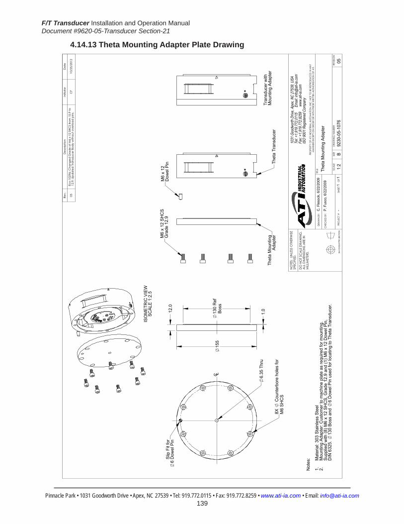
F/T Transducer Installation and Operation ManualDocument #9620-05-Transducer Section-21
Pinnacle Park • 1031 Goodworth Drive • Apex, NC 27539 • Tel: 919.772.0115 • Fax: 919.772.8259 • www.ati-ia.com • Email: [email protected] 139
4.14.13 Theta Mounting Adapter Plate Drawing
3rd
AN
GLE
PRO
JEC
TION
M6
x 12
SH
CS
Gra
de 1
2.9
M6
x 12
Dow
el P
in
Thet
a M
ount
ing
Adap
ter
Thet
a Tr
ansd
ucer
6.35
Thr
u
8X
Cou
nter
bore
hol
es fo
r M
6 SH
CS
Slip
Fit
for
6 D
owel
Pin
C L
155
12.
0
1.0
130
Ref
Boss
Tran
sduc
er w
ithM
ount
ing
Adap
ter
ISO
MET
RIC
VIE
WSC
ALE
1:2.
5
Not
es: Mat
eria
l: 30
3 St
ainl
ess
Stee
l1.
Mou
ntin
g Ad
apte
r: C
usto
mer
to m
achi
ne p
late
as
requ
ired
for m
ount
ing.
2.Su
pplie
d w
ith (8
) M6
x 12
SH
CS,
Gra
de 1
2.9
and
(1) M
6 x
12 D
owel
Pin
, D
IN 6
325.
13
0 Bo
ss a
nd
6 D
owel
Pin
use
d fo
r loc
atin
g to
The
ta T
rans
duce
r.
Rev.
Des
crip
tion
Initi
ator
Dat
e
05Ec
o 10
296;
Cha
nged
Gra
de o
f M6
x 12
SHC
S fro
m 1
0.9
to
12.9
; Upd
ated
Tran
sduc
er B
ody
with
out o
verlo
ad p
ins.
CF
10/2
5/20
12
B1:
21
1RE
VISIO
N
NO
TES:
UN
LESS
OTH
ERW
ISE
SPEC
IFIED
.
DO
NO
T SC
ALE
DRA
WIN
G.
ALL
DIM
ENSI
ON
S A
RE IN
M
ILLIM
ETER
S.
DRA
WN
BY:
CHE
CKE
D B
Y:
C. F
leso
ck, 6
/22/
2009
P. F
usco
, 6/2
2/20
09
TITLE SC
ALE
SIZE
DRA
WIN
G N
UMBE
R
PRO
JEC
T #SH
EET
O
F 92
30-0
5-10
76-
05
PRO
PERT
Y O
F A
TI IN
DUS
TRIA
L A
UTO
MA
TION
, IN
C. N
OT T
O B
E RE
PRO
DUC
ED IN
AN
Y M
AN
NER
EXC
EPT O
N O
RDER
OR
WITH
PRI
OR
WRI
TTEN
AUT
HORI
ZATIO
N O
F A
TI.
1031
Goo
dwor
th Dr
ive, A
pex,
NC 27
539,
USA
Tel: +
1.919
.772.0
115
Em
ail: in
fo@ati
-ia.co
mFa
x: +1
.919.7
72.82
59
www
.ati-ia
.com
ISO
9001
Reg
ister
ed C
ompa
ny
Thet
a M
ount
ing
Adap
ter

F/T Transducer Installation and Operation ManualDocument #9620-05-Transducer Section-21
Pinnacle Park • 1031 Goodworth Drive • Apex, NC 27539 • Tel: 919.772.0115 • Fax: 919.772.8259 • www.ati-ia.com • Email: [email protected] 140
4.14.14 Theta IP60 Transducer Drawing
124
135°
B.C
. 12
5
193.
7
(2)
10 S
lip F
it 8
Cus
tom
er In
terfa
ce(7
)8.
7 Th
ruFo
r M8
SHC
SEq
ually
Spa
ced
Cus
tom
er In
terfa
ceO
ptio
nal M
ount
ing
Side
Pat
tern
B.C
. 18
015
°
135°
(2)
8 Sl
ip F
it 12
Cus
tom
er In
terfa
ce
62.5
00±0
.025
106.
694±
0.02
5
44.1
94±0
.025
77.9
42±0
.025
45±0
.025
101.
236±
0.02
5
131.
933±
0.02
5
57.8
Mux
& D
AQ S
yste
m45° 70
.4N
et S
yste
m
+X
+Y-Y
-X
(6) T
ap M
10x1
.5
10Eq
ually
Spa
ced
Cus
tom
er In
terfa
ce
Con
nect
or F
or C
able
Varie
s D
epen
ding
on
Sens
or S
elec
ted
74
0.6
54.6
Neo
pren
eR
ubbe
r D
ust J
acke
tTo
ol A
dapt
er P
late
Sens
ing
Ref
eren
ceFr
ame
Orig
in
Mou
ntin
g A
dapt
er P
late
+Z
40 H
7,
15C
usto
mer
Inte
rface
10 S
lip F
it 15
Cus
tom
er In
terfa
ce
B.C
. 10
0
50±0
.025
155
45°
Sens
ing
Ref
eren
ceFr
ame
Orig
in(4
) Tap
M12
x1.7
5 15
Equa
lly S
pace
d C
usto
mer
Inte
rface
+X -X
-Y+Y
Not
es:
1. M
ater
ial:
Stai
nles
s St
eel a
nd A
lum
inum
2. D
o no
t tou
ch in
tern
al e
lect
roni
cs o
r ins
trum
enta
tion.
Thi
s co
uld
dam
age
the
trans
duce
r and
will
void
war
rant
y.3.
Sen
sing
Ref
eren
ce F
ram
e O
rigin
at s
urfa
ce c
ente
r of T
ool A
dapt
er.
4. F
or b
est a
ccur
acy,
tran
sduc
er m
ust b
e m
ount
ed to
sur
face
s rig
id
eno
ugh
to s
uppo
rt lo
ads
with
out d
efle
ctio
n.IS
OM
ETR
IC V
IEW
TOO
L SI
DE
SID
E VI
EWM
OU
NTI
NG
SID
E
-Z
Rev.
Des
crip
tion
Initi
ator
Dat
e
03A
dded
Net
Dim
ensio
nsA
LH8/
7/08
04Ec
o 72
55; D
im fr
om c
ente
r to
limits
of c
onne
ctor
blo
ck
cang
ed to
124
mm
from
132
mm
afte
r con
nect
or b
lock
co
mpo
nent
s cha
nged
.LJ
H9/
4/20
09
1031
Goo
dwor
th Dr
ive, A
pex,
NC 27
539,
USA
Tel: +
1.919
.772.0
115
Em
ail: in
fo@ati
-ia.co
mFa
x: +1
.919.7
72.82
59
www
.ati-ia
.com
ISO
9001
Reg
ister
ed C
ompa
ny
NO
TES:
UN
LESS
O
THER
WIS
E SP
ECIFI
ED
DO
NO
T SC
ALE
DRA
WIN
G.
DRA
WN
IN S
OLID
WO
RKS.
ALL
DIM
ENSI
ON
S A
RE
IN M
ILLIM
ETER
S.
3rd
AN
GLE
PRO
JEC
TION
DRA
WN
BY:
CHE
CKE
D B
Y:
WEI
GHT
LBS
:
ASS
EMBL
Y RE
F:
P.Sp
arro
w, 2
/16/
06
D.N
orto
n, 2
/17/
06
TITLE SC
ALE
SIZE
DRA
WIN
G N
UMBE
R
PRO
DUC
T REL
EASE
#D
ATE
:SH
EET
O
F
PRO
PERT
Y O
F A
TI IN
DUS
TRIA
L A
UTO
MA
TION
, IN
C.
NO
T TO
BE
REPR
OD
UCED
IN A
NY
MA
NN
ER E
XCEP
T ON
ORD
ER O
R W
ITH P
RIO
R W
RITT
EN A
UTHO
RIZA
TION
OF
ATI.
IP60
The
ta T
rans
duce
r 9230
-05-
1263
-04
B1:
21
1
19

F/T Transducer Installation and Operation ManualDocument #9620-05-Transducer Section-21
Pinnacle Park • 1031 Goodworth Drive • Apex, NC 27539 • Tel: 919.772.0115 • Fax: 919.772.8259 • www.ati-ia.com • Email: [email protected] 141
4.14.15 Theta IP65 Transducer Drawing
162.
8
B.C
.12
5
(135
°)
123.
2 M
ux &
DAQ
Syst
em
60°C
usto
mer
Inte
rface
Equa
lly S
pace
d(6
) Tap
M10
X1.5
1
1
(2)
10 S
lip F
it 8
Cus
tom
er In
terfa
ce
61.6
Mux
& D
AQ
Syst
em
44.1
94±0
.025
106.
694±
0.02
5
62.5
00±0
.025
70.7
Net
Sys
tem
103.
1N
et S
yste
m
Mem
bran
e Ve
nt
Not
es:
1. M
ater
ial:
Stai
nles
s St
eel
2. S
ensi
ng R
efer
ence
Fra
me
Orig
in a
t
sur
face
cen
ter o
f Too
l Ada
pter
.3.
Do
not d
isas
sem
ble
trans
duce
r. D
oing
so
c
ould
dam
age
trans
duce
r and
will
void
war
rant
y.4.
For
bes
t acc
urac
y, tr
ansd
ucer
mus
t be
mou
nted
to
s
urfa
ces
rigid
eno
ugh
to s
uppo
rt lo
ads
with
out d
efle
ctio
n.
5. C
able
mus
t be
conn
ecte
d to
tran
sduc
er to
mai
ntai
n pr
oper
sea
l.6.
Cab
le is
IP65
rate
d on
ly a
t tra
nsdu
cer e
nd.
Con
nect
or F
or C
able
Varie
s D
epen
ding
on
Sens
or S
elec
ted
74.7
9
2.40
27.9
444
.20
Sens
ing
Ref
eren
ceFr
ame
Orig
in
-Z+Z
Tool
Ada
pter
Plat
eM
ount
ing
Adap
ter P
late
B.C
.10
0
Cus
tom
er In
terfa
ceEq
ually
Spa
ced
(4) T
ap M
12X1
.75
1
5
45°
Cus
tom
er In
terfa
ce10
Slip
Fit
14
40.0
2539
.990
14
Cus
tom
er In
terfa
ce
50±0
.025
157.
48
Sens
ing
Ref
eren
ceFr
ame
Orig
in
ISO
MET
RIC
VIE
W
MO
UN
TIN
G S
IDE
SID
E VI
EWTO
OL
SID
E
+Y
-X
-Y
+Y-Y
+X -X
+X
Rev.
Des
crip
tion
Initi
ator
Dat
e
01In
itial
Issu
ePS
2/16
/200
6
02A
dded
Net
Dim
ensio
nsA
LH8/
8/20
08
1031
Goo
dwor
th Dr
ive, A
pex,
NC 27
539,
USA
Tel: +
1.919
.772.0
115
Em
ail: in
fo@ati
-ia.co
mFa
x: +1
.919.7
72.82
59
www
.ati-ia
.com
ISO
9001
Reg
ister
ed C
ompa
ny
NO
TES:
UN
LESS
O
THER
WIS
E SP
ECIFI
ED
DO
NO
T SC
ALE
DRA
WIN
G.
DRA
WN
IN S
OLID
WO
RKS.
ALL
DIM
ENSI
ON
S A
RE IN
MILL
IMET
ERS.
3rd
AN
GLE
PRO
JEC
TION
DRA
WN
BY:
CHE
CKE
D B
Y:
WEI
GHT
LBS
:
ASS
EMBL
Y RE
F:
P.Sp
arro
w, 2
/16/
06
D.N
orto
n, 2
/17/
06
TITLE SC
ALE
SIZE
DRA
WIN
G N
UMBE
R
PRO
DUC
T REL
EASE
#D
ATE
:SH
EET
O
F
PRO
PERT
Y O
F A
TI IN
DUS
TRIA
L A
UTO
MA
TION
, IN
C.
NO
T TO
BE
REPR
OD
UCED
IN A
NY
MA
NN
ER E
XCEP
T ON
ORD
ER O
R W
ITH P
RIO
R W
RITT
EN A
UTHO
RIZA
TION
OF
ATI.
IP65
The
ta T
rans
duce
r 9230
-05-
1268
-02
B1:
1.5
11
20

F/T Transducer Installation and Operation ManualDocument #9620-05-Transducer Section-21
Pinnacle Park • 1031 Goodworth Drive • Apex, NC 27539 • Tel: 919.772.0115 • Fax: 919.772.8259 • www.ati-ia.com • Email: [email protected] 142
4.14.16 ThetaIP68TransducerDrawing
3rd
AN
GLE
PRO
JEC
TION
123.
2M
ux &
DAQ
Syst
em
162.
8
B.C
.12
5
Cus
tom
er In
terfa
ceEq
ually
Spa
ced
6X T
ap M
10X1
.511
135°
62.5
00±0
.025
106.
694±
0.02
5
44.1
94±0
.025
2X10
Slip
Fit
8C
usto
mer
Inte
rface
60°
61M
ux &
DAQ
Syst
em 70N
et S
yste
m
116.
2N
et S
yste
m
Con
nect
or fo
r Cab
leVa
ries
Dep
endi
ng o
nSe
nsor
Sel
ecte
d
MO
UN
TIN
G S
IDE
+X
+Y
-X
-Y
44.2
28.22.
4
74.8
Sens
ing
Ref
eren
ceFr
ame
Orig
in
-Z+Z
Mou
ntin
g Ad
apte
rPl
ate
Tool
Ada
pter
Plat
e
SID
E VI
EW
45°
B.C
.10
0
10 S
lip F
it 14
Cus
tom
er In
terfa
ce
40.0
2539
.990
14
Cus
tom
er In
terfa
ce
50.0
000.
025
157.
48
4X T
ap M
12X1
.75
15
Equa
lly S
pace
dC
usto
mer
Inte
rface
Sens
ing
Ref
eren
ceFr
ame
Orig
in
TOO
L SI
DE
+X
+Y-Y
-X
ISO
MET
RIC
VIE
W
Not
es:
1. M
ater
ial:
Stai
nles
s St
eel
2. S
ensi
ng R
efer
ence
Fra
me
Orig
in a
t sur
face
cen
ter o
f Too
l Ada
pter
.3.
Do
not d
isas
sem
ble
trans
duce
r. D
oing
so
coul
d da
mag
e tra
nsdu
cer
a
nd w
ill vo
id w
arra
nty.
4. F
or b
est a
ccur
acy,
tran
sduc
er m
ust b
e m
ount
ed to
sur
face
s rig
id
eno
ugh
to s
uppo
rt lo
ads
with
out d
efle
ctio
n.
5. C
able
mus
t be
conn
ecte
d to
tran
sduc
er to
mai
ntai
n pr
oper
sea
l.6.
Cab
le is
IP68
rate
d on
ly a
t tra
nsdu
cer e
nd.
Tran
sduc
er is
IP68
rate
d
in
fresh
wat
er e
nviro
nmen
t at a
dep
th o
f up
to 1
0 m
eter
s.
Rev.
Des
crip
tion
Initi
ator
Dat
e
04EC
1064
0: A
d N
et S
yste
m d
etai
ls to
the
draw
ing
JW02
/05/
2013
B1:
1.5
11
REVI
SION
NO
TES:
UN
LESS
OTH
ERW
ISE
SPEC
IFIED
.
DO
NO
T SC
ALE
DRA
WIN
G.
ALL
DIM
ENSI
ON
S A
RE IN
M
ILLIM
ETER
S.
DRA
WN
BY:
CHE
CKE
D B
Y:
P.Sp
arro
w, 2
/16/
06
D. N
orto
n 2/
17/0
6
TITLE SC
ALE
SIZE
DRA
WIN
G N
UMBE
R
PRO
JEC
T #SH
EET
O
F 92
30-0
5-12
7304
PRO
PERT
Y O
F A
TI IN
DUS
TRIA
L A
UTO
MA
TION
, IN
C. N
OT T
O B
E RE
PRO
DUC
ED IN
AN
Y M
AN
NER
EXC
EPT O
N O
RDER
OR
WITH
PRI
OR
WRI
TTEN
AUT
HORI
ZATIO
N O
F A
TI.
1031
Goo
dwor
th Dr
ive, A
pex,
NC 27
539,
USA
Tel: +
1.919
.772.0
115
Em
ail: in
fo@ati
-ia.co
mFa
x: +1
.919.7
72.82
59
www
.ati-ia
.com
ISO
9001
Reg
ister
ed C
ompa
ny
IP68
-10m
TH
ETA
Tran
sduc
er

F/T Transducer Installation and Operation ManualDocument #9620-05-Transducer Section-21
Pinnacle Park • 1031 Goodworth Drive • Apex, NC 27539 • Tel: 919.772.0115 • Fax: 919.772.8259 • www.ati-ia.com • Email: [email protected] 143
4.15 Omega85Specifications(IncludesIP60/IP65/IP68Versions)4.15.1 Omega85PhysicalProperties
Table4.84—Omega85PhysicalPropertiesSingle-Axis Overload (US)StandardUnits (SI)MetricUnitsFxy ±2800 lbf ±13000 NFz ±6100 lbf ±27000 NTxy ±4400 inf-lb ±500 NmTz ±5400 inf-lb ±610 NmStiffness(Calculated) X-axis&Y-axisforces(Kx,Ky) 4.4x10⁵ lb/in 7.7x10⁷ N/m Z-axisforce(Kz) 6.8x10⁵ lb/in 1.2x10⁸ N/m X-axis&Y-axistorque(Ktx,Kty) 7.2x10⁵ lbf-in/rad 8.1x10⁴ Nm/rad Z-axistorque(Ktz) 1.2x10⁶ lbf-in/rad 1.3x10⁵ Nm/rad Resonant Frequency Fx, Fy, Tz 2100 Hz 2100 HzFz, Tx, Ty 3000 Hz 3000 HzPhysicalSpecifications Weight1 1.45 lb 0.658 kgDiameter1 3.35 in 85.1 mmHeight1 1.32 in 33.4 mmNote: 1.Specificationsincludestandardinterfaceplates.
4.15.2 Omega85IP65/IP68PhysicalPropertiesTable4.85—Omega85IP65/IP68PhysicalProperties
Single-Axis Overload (US)StandardUnits (SI)MetricUnitsFxy ±2800 lbf ±13000 NFz ±6100 lbf ±27000 NTxy ±4400 inf-lb ±500 NmTz ±5400 inf-lb ±610 NmStiffness(Calculated) X-axis&Y-axisforces(Kx,Ky) 4.4x10⁵ lb/in 7.7x10⁷ N/m Z-axisforce(Kz) 6.8x10⁵ lb/in 1.2x10⁸ N/m X-axis&Y-axistorque(Ktx,Kty) 7.2x10⁵ lbf-in/rad 8.1x10⁴ Nm/rad Z-axistorque(Ktz) 1.2x10⁶ lbf-in/rad 1.3x10⁵ Nm/rad Resonant Frequency Fx, Fy, Tz N/A N/AFz, Tx, Ty N/A N/APhysicalSpecifications Weight1 4.2 lb 1.91 kgDiameter1 3.65 in 92.7 mmHeight1 1.52 in 38.7 mmNote: 1.Specificationsincludestandardinterfaceplates.
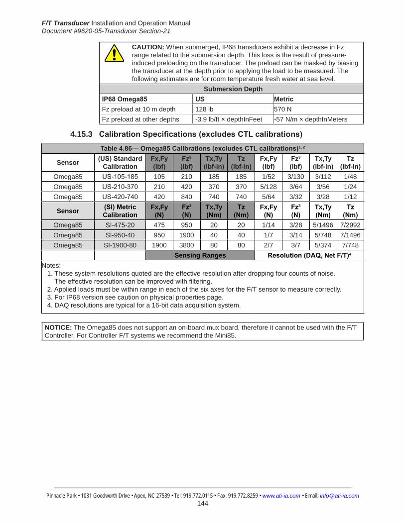
F/T Transducer Installation and Operation ManualDocument #9620-05-Transducer Section-21
Pinnacle Park • 1031 Goodworth Drive • Apex, NC 27539 • Tel: 919.772.0115 • Fax: 919.772.8259 • www.ati-ia.com • Email: [email protected] 144
CAUTION: When submerged, IP68 transducers exhibit a decrease in Fz range related to the submersion depth. This loss is the result of pressure-induced preloading on the transducer. The preload can be masked by biasing the transducer at the depth prior to applying the load to be measured. The following estimates are for room temperature fresh water at sea level.
Submersion DepthIP68Omega85 US MetricFz preload at 10 m depth 128 lb 570 NFz preload at other depths -3.9 lb/ft × depthInFeet -57 N/m × depthInMeters
4.15.3 CalibrationSpecifications(excludesCTLcalibrations)
Table4.86—Omega85Calibrations(excludesCTLcalibrations)1, 2
Sensor (US)Standard Calibration
Fx,Fy (lbf)
Fz3 (lbf)
Tx,Ty (lbf-in)
Tz (lbf-in)
Fx,Fy (lbf)
Fz3 (lbf)
Tx,Ty (lbf-in)
Tz (lbf-in)
Omega85 US-105-185 105 210 185 185 1/52 3/130 3/112 1/48Omega85 US-210-370 210 420 370 370 5/128 3/64 3/56 1/24Omega85 US-420-740 420 840 740 740 5/64 3/32 3/28 1/12
Sensor (SI)Metric Calibration
Fx,Fy (N)
Fz3 (N)
Tx,Ty (Nm)
Tz (Nm)
Fx,Fy (N)
Fz3 (N)
Tx,Ty (Nm)
Tz (Nm)
Omega85 SI-475-20 475 950 20 20 1/14 3/28 5/1496 7/2992Omega85 SI-950-40 950 1900 40 40 1/7 3/14 5/748 7/1496Omega85 SI-1900-80 1900 3800 80 80 2/7 3/7 5/374 7/748
Sensing Ranges Resolution(DAQ,NetF/T)4
Notes: 1. These system resolutions quoted are the effective resolution after dropping four counts of noise. Theeffectiveresolutioncanbeimprovedwithfiltering. 2. Applied loads must be within range in each of the six axes for the F/T sensor to measure correctly. 3. For IP68 version see caution on physical properties page. 4. DAQ resolutions are typical for a 16-bit data acquisition system.
NOTICE: The Omega85 does not support an on-board mux board, therefore it cannot be used with the F/T Controller. For Controller F/T systems we recommend the Mini85.

F/T Transducer Installation and Operation ManualDocument #9620-05-Transducer Section-21
Pinnacle Park • 1031 Goodworth Drive • Apex, NC 27539 • Tel: 919.772.0115 • Fax: 919.772.8259 • www.ati-ia.com • Email: [email protected] 145
4.15.4 Omega85(USCalibrationComplexLoading)(IncludesIP65/IP68)1
HelpOmega85
US-105-185 US-210-370 US-420-740
Note: 1. For IP68 version see caution on physical properties page.

F/T Transducer Installation and Operation ManualDocument #9620-05-Transducer Section-21
Pinnacle Park • 1031 Goodworth Drive • Apex, NC 27539 • Tel: 919.772.0115 • Fax: 919.772.8259 • www.ati-ia.com • Email: [email protected] 146
4.15.5 Omega85(SICalibrationComplexLoading)(IncludesIP65/IP68)1
HelpOmega85
SI-475-20 SI-950-40 SI-1900-80
Note: 1. For IP68 version see caution on physical properties page.

F/T Transducer Installation and Operation ManualDocument #9620-05-Transducer Section-21
Pinnacle Park • 1031 Goodworth Drive • Apex, NC 27539 • Tel: 919.772.0115 • Fax: 919.772.8259 • www.ati-ia.com • Email: [email protected] 147
4.15.6 Omega85TransducerDrawing
3rd
AN
GLE
PRO
JEC
TION
31.7
DAQ
Sys
tem
37±0
.025
71.3
06±0
.025
13.8
60±0
.025
(See
Not
e 4)
2X
5 Sl
ip F
it 11
Cus
tom
er In
terfa
ce
(See
Not
e 4)
Cus
tom
er In
terfa
cePa
irs E
qual
ly S
pace
d6X
Tap
M5X
0.8
11
60.1
20°
Typ.
10°
69.5
°
44.2
Net
Sys
tem
B.C
. 74
+X
+Y
-X
-Y-Z
+Z
MO
UN
TIN
G S
IDE
SID
E VI
EWTO
OL
SID
E
ISO
MET
RIC
VIE
W
-Y
+X
+Y
-X
Con
nect
or F
or C
able
Varie
s D
epen
ding
On
Sens
or S
elec
ted
85
33.4 19
.5
14D
AQ S
yste
m18
.3N
et S
yste
m
Mou
ntin
gAd
apte
rPl
ate
Tool
Adap
ter
Plat
e
Sens
ing
Ref
eren
ceFr
ame
Orig
in
40°
Typ.
(See
Not
e 4)
Cus
tom
er In
terfa
ce2X
5
Slip
Fit
6.5
(See
Not
e 4)
Cus
tom
er In
terfa
cePa
irs E
qual
ly S
pace
d6X
Tap
M5X
0.8
6.523
.383
±0.0
25
40.5
00±0
.02527
±0.0
25
20°
B.C
. 54
Sens
ing
Ref
eren
ceFr
ame
Orig
in
Not
es: M
ater
ial:
Har
dene
d st
ainl
ess
stee
l and
alu
min
um.
1.Se
nsin
g R
efer
ence
Fra
me
Orig
in a
t sur
face
cen
ter o
f Too
l Ada
pter
.2.
Do
not d
isas
sem
ble
trans
duce
r. D
oing
so
3.co
uld
dam
age
trans
duce
r and
will
void
war
rant
y.D
O N
OT
EXC
EED
INTE
RFA
CE
DEP
TH, M
AY
CA
USE
DA
MA
GE.
4.Fo
r bes
t acc
urac
y, tr
ansd
ucer
mus
t be
mou
nted
to s
urfa
ces
5.rig
id e
noug
h to
sup
port
load
s w
ithou
t def
lect
ion.
Rev.
Des
crip
tion
Initi
ator
Dat
e
03EC
O 9
072:
Add
Net
Sys
tem
con
nect
or b
lock
out
line
to
Side
View
JW10
/25/
2011
B1:
11
1RE
VISIO
N
NO
TES:
UN
LESS
OTH
ERW
ISE
SPEC
IFIED
.
DO
NO
T SC
ALE
DRA
WIN
G.
ALL
DIM
ENSI
ON
S A
RE IN
M
ILLIM
ETER
S.
DRA
WN
BY:
CHE
CKE
D B
Y:
D. S
wan
son
8/28
/08
P. F
usco
8/2
8/08
TITLE SC
ALE
SIZE
DRA
WIN
G N
UMBE
R
PRO
JEC
T #SH
EET
O
F 92
30-0
5-13
41-
03
PRO
PERT
Y O
F A
TI IN
DUS
TRIA
L A
UTO
MA
TION
, IN
C. N
OT T
O B
E RE
PRO
DUC
ED IN
AN
Y M
AN
NER
EXC
EPT O
N O
RDER
OR
WITH
PRI
OR
WRI
TTEN
AUT
HORI
ZATIO
N O
F A
TI.
1031
Goo
dwor
th Dr
ive, A
pex,
NC 27
539,
USA
Tel: +
1.919
.772.0
115
Em
ail: in
fo@ati
-ia.co
mFa
x: +1
.919.7
72.82
59
www
.ati-ia
.com
ISO
9001
Reg
ister
ed C
ompa
ny
Om
ega8
5 Tr
ansd
ucer
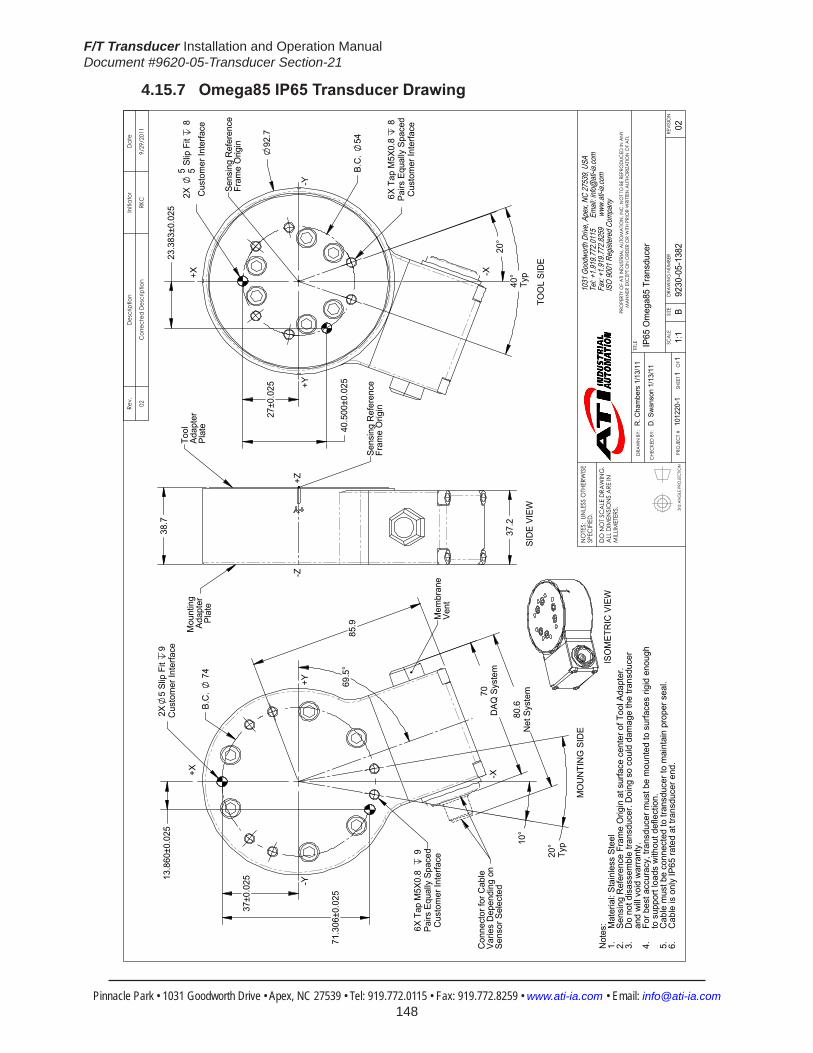
F/T Transducer Installation and Operation ManualDocument #9620-05-Transducer Section-21
Pinnacle Park • 1031 Goodworth Drive • Apex, NC 27539 • Tel: 919.772.0115 • Fax: 919.772.8259 • www.ati-ia.com • Email: [email protected] 148
4.15.7 Omega85IP65TransducerDrawing
3rd
AN
GLE
PRO
JEC
TION
37±0
.025
71.3
06±0
.025
13.8
60±0
.025
2X5
Slip
Fit
9C
usto
mer
Inte
rface
Cus
tom
er In
terfa
cePa
irs E
qual
ly S
pace
d6X
Tap
M5X
0.8
9
10°
20°
Typ
85.9
70D
AQ S
yste
m
B.C
. 7
4
69.5
°
80.6
Net
Sys
tem
+X -X
-Y+Y
MO
UN
TIN
G S
IDE
Con
nect
or fo
r Cab
leVa
ries
Dep
endi
ng o
n Se
nsor
Sel
ecte
d
Mem
bran
eVe
nt
38.7
37.2
+Z-Z
Tool
Ad
apte
rPl
ate
Mou
ntin
g Ad
apte
rPl
ate
Sens
ing
Ref
eren
ceFr
ame
Orig
in
SID
E VI
EW
23.3
83±0
.025
40.5
00±0
.025
27±0
.025
20°
40°
Typ
Cus
tom
er In
terfa
cePa
irs E
qual
ly S
pace
d6X
Tap
M5X
0.8
8
92.7
B.C
. 54
Cus
tom
er In
terfa
ce2X
5 5 S
lip F
it 8
+Y-Y
-X+X
Sens
ing
Ref
eren
ceFr
ame
Orig
in
TOO
L SI
DE
ISO
MET
RIC
VIE
WN
otes
: Mat
eria
l: St
ainl
ess
Stee
l1.
Sens
ing
Ref
eren
ce F
ram
e O
rigin
at s
urfa
ce c
ente
r of T
ool A
dapt
er.
2.D
o no
t dis
asse
mbl
e tra
nsdu
cer.
Doi
ng s
o co
uld
dam
age
the
trans
duce
r3.
and
will
void
war
rant
y.Fo
r bes
t acc
urac
y, tr
ansd
ucer
mus
t be
mou
nted
to s
urfa
ces
rigid
eno
ugh
4.to
sup
port
load
s w
ithou
t def
lect
ion.
Cab
le m
ust b
e co
nnec
ted
to tr
ansd
ucer
to m
aint
ain
prop
er s
eal.
5.C
able
is o
nly
IP65
rate
d at
tran
sduc
er e
nd.
6.
Rev.
Des
crip
tion
Initi
ator
Dat
e
02C
orre
cted
Des
crip
tion
RKC
9/29
/201
1
B1:
11
1RE
VISIO
N
NO
TES:
UN
LESS
OTH
ERW
ISE
SPEC
IFIED
.
DO
NO
T SC
ALE
DRA
WIN
G.
ALL
DIM
ENSI
ON
S A
RE IN
M
ILLIM
ETER
S.
DRA
WN
BY:
CHE
CKE
D B
Y:
R. C
ham
bers
1/1
3/11
D. S
wan
son
1/13
/11
TITLE SC
ALE
SIZE
DRA
WIN
G N
UMBE
R
PRO
JEC
T #SH
EET
O
F 92
30-0
5-13
8210
1220
-102
PRO
PERT
Y O
F A
TI IN
DUS
TRIA
L A
UTO
MA
TION
, IN
C. N
OT T
O B
E RE
PRO
DUC
ED IN
AN
Y M
AN
NER
EXC
EPT O
N O
RDER
OR
WITH
PRI
OR
WRI
TTEN
AUT
HORI
ZATIO
N O
F A
TI.
1031
Goo
dwor
th Dr
ive, A
pex,
NC 27
539,
USA
Tel: +
1.919
.772.0
115
Em
ail: in
fo@ati
-ia.co
mFa
x: +1
.919.7
72.82
59
www
.ati-ia
.com
ISO
9001
Reg
ister
ed C
ompa
ny
IP65
Om
ega8
5 Tr
ansd
ucer

F/T Transducer Installation and Operation ManualDocument #9620-05-Transducer Section-21
Pinnacle Park • 1031 Goodworth Drive • Apex, NC 27539 • Tel: 919.772.0115 • Fax: 919.772.8259 • www.ati-ia.com • Email: [email protected] 149
4.15.8 Omega85IP68TransducerDrawing
3rd
AN
GLE
PRO
JEC
TION
37±0
.025
71.3
06±0
.025
13.8
60±0
.025
2X5
Slip
Fit
9C
usto
mer
Inte
rface
Cus
tom
er In
terfa
cePa
irs E
qual
ly S
pace
d6X
Tap
M5X
0.8
9
10°
20°
Typ
85.9
B.C
. 7
4
68.9
DAQ
Sys
tem69
.5°
79.9
Net
Sys
tem
+X -X
-Y+Y
MO
UN
TIN
G S
IDE
Con
nect
or fo
r Cab
leVa
ries
Dep
endi
ng o
n Se
nsor
Sel
ecte
d
38.7
37.2
+Z-Z
Tool
Ad
apte
rPl
ate
Mou
ntin
g Ad
apte
rPl
ate
Sens
ing
Ref
eren
ceFr
ame
Orig
in
SID
E VI
EW
23.3
83±0
.025
40.5
00±0
.025
27±0
.025
20°
40°
Typ
Cus
tom
er In
terfa
cePa
irs E
qual
ly S
pace
d6X
Tap
M5X
0.8
8
92.7
B.C
. 54
Cus
tom
er In
terfa
ce2X
5 5 S
lip F
it 8
+Y-Y
-X+X
Sens
ing
Ref
eren
ceFr
ame
Orig
in
TOO
L SI
DE
ISO
MET
RIC
VIE
WN
otes
: Mat
eria
l: St
ainl
ess
Stee
l1.
Sens
ing
Ref
eren
ce F
ram
e O
rigin
at s
urfa
ce c
ente
r of T
ool A
dapt
er.
2.D
o no
t dis
asse
mbl
e tra
nsdu
cer.
Doi
ng s
o co
uld
dam
age
the
trans
duce
r3.
and
will
void
war
rant
y.Fo
r bes
t acc
urac
y, tr
ansd
ucer
mus
t be
mou
nted
to s
urfa
ces
rigid
eno
ugh
4.to
sup
port
load
s w
ithou
t def
lect
ion.
Cab
le m
ust b
e co
nnec
ted
to tr
ansd
ucer
to m
aint
ain
prop
er s
eal.
5.C
able
is o
nly
IP68
rate
d at
tran
sduc
er e
nd.
6.
Rev.
Des
crip
tion
Initi
ator
Dat
e
01In
itial
Dra
win
gRK
C6/
29/2
011
B1:
11
1RE
VISIO
N
NO
TES:
UN
LESS
OTH
ERW
ISE
SPEC
IFIED
.
DO
NO
T SC
ALE
DRA
WIN
G.
ALL
DIM
ENSI
ON
S A
RE IN
M
ILLIM
ETER
S.
DRA
WN
BY:
CHE
CKE
D B
Y:
R. C
ham
bers
6/2
9/11
D. S
wan
son
6/29
/11
TITLE SC
ALE
SIZE
DRA
WIN
G N
UMBE
R
PRO
JEC
T #SH
EET
O
F 92
30-0
5-13
9610
1220
-101
PRO
PERT
Y O
F A
TI IN
DUS
TRIA
L A
UTO
MA
TION
, IN
C. N
OT T
O B
E RE
PRO
DUC
ED IN
AN
Y M
AN
NER
EXC
EPT O
N O
RDER
OR
WITH
PRI
OR
WRI
TTEN
AUT
HORI
ZATIO
N O
F A
TI.
1031
Goo
dwor
th Dr
ive, A
pex,
NC 27
539,
USA
Tel: +
1.919
.772.0
115
Em
ail: in
fo@ati
-ia.co
mFa
x: +1
.919.7
72.82
59
www
.ati-ia
.com
ISO
9001
Reg
ister
ed C
ompa
ny
IP68
Om
ega8
5 Tr
ansd
ucer

F/T Transducer Installation and Operation ManualDocument #9620-05-Transducer Section-21
Pinnacle Park • 1031 Goodworth Drive • Apex, NC 27539 • Tel: 919.772.0115 • Fax: 919.772.8259 • www.ati-ia.com • Email: [email protected] 150
4.16 Omega160Specifications(IncludesIP60/IP65/IP68Versions)4.16.1 Omega160 Physical Properties
Table4.87—Omega160 Physical PropertiesSingle-Axis Overload (US)StandardUnits (SI)MetricUnitsFxy ±3900 lbf ±18000 NFz ±11000 lbf ±48000 NTxy ±15000 inf-lb ±1700 NmTz ±17000 inf-lb ±1900 NmStiffness(Calculated) X-axis&Y-axisforces(Kx,Ky) 4.0x10⁵ lb/in 7.0x10⁷ N/m Z-axisforce(Kz) 6.8x10⁵ lb/in 1.2x10⁸ N/m X-axis&Y-axistorque(Ktx,Kty) 2.9x10⁶ lbf-in/rad 3.3x10⁵ Nm/rad Z-axistorque(Ktz) 4.6x10⁶ lbf-in/rad 5.2x10⁵ Nm/rad Resonant Frequency Fx, Fy, Tz 1300 Hz 1300 HzFz, Tx, Ty 1000 Hz 1000 HzPhysicalSpecifications Weight1 6 lb 2.72 kgDiameter1 6.16 in 157 mmHeight1 2.2 in 55.9 mmNote: 1.Specificationsincludestandardinterfaceplates.
4.16.2 Omega160IP160PhysicalProperties(IncludesECAT)Table4.88—Omega160 IP160 Physical Properties
Single-Axis Overload (US)StandardUnits (SI)MetricUnitsFxy ±3900 lbf ±18000 NFz ±11000 lbf ±48000 NTxy ±15000 inf-lb ±1700 NmTz ±17000 inf-lb ±1900 NmStiffness(Calculated) X-axis&Y-axisforces(Kx,Ky) 4.0x10⁵ lb/in 7.0x10⁷ N/m Z-axisforce(Kz) 6.8x10⁵ lb/in 1.2x10⁸ N/m X-axis&Y-axistorque(Ktx,Kty) 2.9x10⁶ lbf-in/rad 3.3x10⁵ Nm/rad Z-axistorque(Ktz) 4.6x10⁶ lbf-in/rad 5.2x10⁵ Nm/rad Resonant Frequency Fx, Fy, Tz 1100 Hz 1100 HzFz, Tx, Ty 1000 Hz 1000 HzPhysicalSpecifications Weight1 16.9 lb 7.67 kgDiameter1 7.63 in 194 mmHeight1 2.27 in 57.7 mmNote: 1.Specificationsincludestandardinterfaceplates.
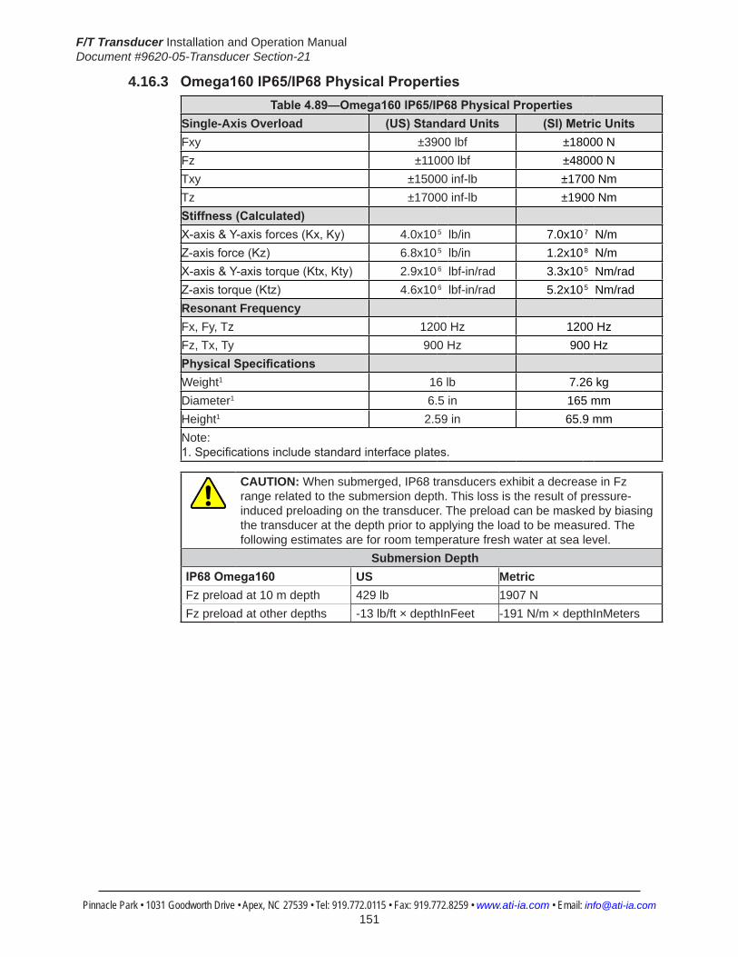
F/T Transducer Installation and Operation ManualDocument #9620-05-Transducer Section-21
Pinnacle Park • 1031 Goodworth Drive • Apex, NC 27539 • Tel: 919.772.0115 • Fax: 919.772.8259 • www.ati-ia.com • Email: [email protected] 151
4.16.3 Omega160IP65/IP68PhysicalPropertiesTable4.89—Omega160IP65/IP68PhysicalProperties
Single-Axis Overload (US)StandardUnits (SI)MetricUnitsFxy ±3900 lbf ±18000 NFz ±11000 lbf ±48000 NTxy ±15000 inf-lb ±1700 NmTz ±17000 inf-lb ±1900 NmStiffness(Calculated) X-axis&Y-axisforces(Kx,Ky) 4.0x10⁵ lb/in 7.0x10⁷ N/m Z-axisforce(Kz) 6.8x10⁵ lb/in 1.2x10⁸ N/m X-axis&Y-axistorque(Ktx,Kty) 2.9x10⁶ lbf-in/rad 3.3x10⁵ Nm/rad Z-axistorque(Ktz) 4.6x10⁶ lbf-in/rad 5.2x10⁵ Nm/rad Resonant Frequency Fx, Fy, Tz 1200 Hz 1200 HzFz, Tx, Ty 900 Hz 900 HzPhysicalSpecifications Weight1 16 lb 7.26 kgDiameter1 6.5 in 165 mmHeight1 2.59 in 65.9 mmNote: 1.Specificationsincludestandardinterfaceplates.
CAUTION: When submerged, IP68 transducers exhibit a decrease in Fz range related to the submersion depth. This loss is the result of pressure-induced preloading on the transducer. The preload can be masked by biasing the transducer at the depth prior to applying the load to be measured. The following estimates are for room temperature fresh water at sea level.
Submersion DepthIP68Omega160 US MetricFz preload at 10 m depth 429 lb 1907 NFz preload at other depths -13 lb/ft × depthInFeet -191 N/m × depthInMeters

F/T Transducer Installation and Operation ManualDocument #9620-05-Transducer Section-21
Pinnacle Park • 1031 Goodworth Drive • Apex, NC 27539 • Tel: 919.772.0115 • Fax: 919.772.8259 • www.ati-ia.com • Email: [email protected] 152
4.16.4 CalibrationSpecifications(excludesCTLcalibrations)
Table 4.90—Omega160Calibrations(excludesCTLcalibrations)1, 2
Sensor (US)Standard Calibration
Fx,Fy (lbf)
Fz3 (lbf)
Tx,Ty (lbf-in)
Tz (lbf-in)
Fx,Fy (lbf)
Fz3 (lbf)
Tx,Ty (lbf-in)
Tz (lbf-in)
Omega160 US-200-1000 200 500 1000 1000 1/32 1/16 1/8 1/8Omega160 US-300-1800 300 875 1800 1800 5/68 5/34 5/16 5/16Omega160 US-600-3600 600 1500 3600 3600 1/8 1/4 1/2 1/4
Sensor (SI)Metric Calibration
Fx,Fy (N)
Fz3 (N)
Tx,Ty (Nm)
Tz (Nm)
Fx,Fy (N)
Fz3 (N)
Tx,Ty (Nm)
Tz (Nm)
Omega160 SI-1000-120 1000 2500 120 120 1/4 1/4 1/40 1/80Omega160 SI-1500-240 1500 3750 240 240 1/4 1/2 1/20 1/40Omega160 SI-2500-400 2500 6250 400 400 1/2 3/4 1/20 1/20
Sensing Ranges Resolution(DAQ,NetF/T)4
Notes: 1. These system resolutions quoted are the effective resolution after dropping four counts of noise. Theeffectiveresolutioncanbeimprovedwithfiltering. 2. Applied loads must be within range in each of the six axes for the F/T sensor to measure correctly. 3. For IP68 version see caution on physical properties page. 4. DAQ resolutions are typical for a 16-bit data acquisition system.
4.16.5 CTLCalibrationSpecifications
Table 4.91— Omega160 CTL Calibrations1, 2
Sensor (US)Standard Calibration
Fx,Fy (lbf)
Fz3 (lbf)
Tx,Ty (lbf-in)
Tz (lbf-in)
Fx,Fy (lbf)
Fz3 (lbf)
Tx,Ty (lbf-in)
Tz (lbf-in)
Omega160 US-200-1000 200 500 1000 1000 1/16 1/8 1/4 1/4Omega160 US-300-1800 300 875 1800 1800 5/34 5/17 5/8 5/8Omega160 US-600-3600 600 1500 3600 3600 1/4 1/2 1 1/2
Sensor (SI)Metric Calibration
Fx,Fy (N)
Fz3 (N)
Tx,Ty (Nm)
Tz (Nm)
Fx,Fy (N)
Fz3 (N)
Tx,Ty (Nm)
Tz (Nm)
Omega160 SI-1000-120 1000 2500 120 120 1/2 1/2 1/20 1/40Omega160 SI-1500-240 1500 3750 240 240 1/2 1 1/10 1/20Omega160 SI-2500-400 2500 6250 400 400 1 1 1/2 1/10 1/10
Sensing Ranges Resolution(Controller)Notes: 1. CTL resolutions are typical. System resolutions quoted are the effective resolution after dropping eight countsofnoise.Theeffectiveresolutioncanbeimprovedwithfiltering. 2. Applied loads must be within range in each of the six axes for the F/T sensor to measure correctly. 3. For IP68 version see caution on physical properties page.

F/T Transducer Installation and Operation ManualDocument #9620-05-Transducer Section-21
Pinnacle Park • 1031 Goodworth Drive • Apex, NC 27539 • Tel: 919.772.0115 • Fax: 919.772.8259 • www.ati-ia.com • Email: [email protected] 153
4.16.6 Analog Output
Table 4.92— Omega160 Analog Output
Sensor (US)Standard Calibration
Fx,Fy (lbf)
Fz2 (lbf)
Tx,Ty,Tz (lbf-in)
Fx,Fy (lbf/V)
Fz2 (lbf/V)
Tx,Ty,Tz (lbf-in/V)
Omega160 US-200-1000 ±200 ±500 ±1000 20 50 100Omega160 US-300-1800 ±300 ±875 ±1800 30 87.5 180Omega160 US-600-3600 ±600 ±1500 ±3600 60 150 360
Sensor (SI)Metric Calibration
Fx,Fy (N)
Fz (N)
Tx,Ty,Tz (Nmm)
Fx,Fy (N/V)
Fz2 (N/V)
Tx,Ty,Tz (Nm/V)
Omega160 SI-1000-120 ±1000 ±2500 ±120 100 250 12Omega160 SI-1500-240 ±1500 ±3750 ±240 150 375 24Omega160 SI-2500-400 ±2500 ±6250 ±400 250 625 40
Analog Output Range Analog±10VSensitivity1
Notes: 1. ±5V Sensitivity values are double the listed ±10V Sensitivity values. 2. For IP68 version see caution on physical properties page.
4.16.7 CountsValueTable 4.93—CountsValue
Sensor Calibration Fx,Fy,Fz (/lbf)
Tx,Ty,Tz (/lbf-in)
Fx,Fy,Fz (/N)
Tx,Ty,Tz (/Nm)
Omega160 US-200–1000/SI-1000–120 128 64 32 320Omega160 US-300–1800/SI-1500–240 54.4 12.8 16 160Omega160 US-600–3600/SI-2500–400 32 16 16 80Omega160 Tool Transform Factor See Tool Transform Factor table
CountsValue–Standard(US) CountsValue–Metric(SI)
4.16.8 Tool Transform Factor
Table 4.94—Tool Transform FactorSensor Calibration US(English) SI(Metric)
Omega160 US-200–1000/SI-1000–120 0.02 in/lbf 1 mm/NOmega160 US-300–1800/SI-1500–240 0.0425 in/lbf 1 mm/NOmega160 US-600–3600/SI-2500–400 0.02 in/lbf 2 mm/N

F/T Transducer Installation and Operation ManualDocument #9620-05-Transducer Section-21
Pinnacle Park • 1031 Goodworth Drive • Apex, NC 27539 • Tel: 919.772.0115 • Fax: 919.772.8259 • www.ati-ia.com • Email: [email protected] 154
4.16.9 Omega160(USCalibrationComplexLoading) (IncludesIP60/IP65/IP68)1
HelpOmega160
US-200-1000 US-300-1800 US-600-3600
Note: 1. For IP68 version see caution on physical properties page.

F/T Transducer Installation and Operation ManualDocument #9620-05-Transducer Section-21
Pinnacle Park • 1031 Goodworth Drive • Apex, NC 27539 • Tel: 919.772.0115 • Fax: 919.772.8259 • www.ati-ia.com • Email: [email protected] 155
4.16.10 Omega160(SICalibrationComplexLoading) (IncludesIP60/IP65/IP68)1
HelpOmega160
SI-1000-120 SI-1500-240 SI-2500-400
Note: 1. For IP68 version see caution on physical properties page.

F/T Transducer Installation and Operation ManualDocument #9620-05-Transducer Section-21
Pinnacle Park • 1031 Goodworth Drive • Apex, NC 27539 • Tel: 919.772.0115 • Fax: 919.772.8259 • www.ati-ia.com • Email: [email protected] 156
4.16.11 Omega160 Transducer without Mounting Adapter Drawing
3rd
AN
GLE
PRO
JEC
TION
50±0
.013
B.C
.10
0(4
) Tap
M10
x 1
.5
10Eq
ually
Spa
ced
Cus
tom
er In
terfa
ce(S
ee N
ote
3)
-X+X
-Y+Y
TOO
L SI
DE
Sens
ing
Refe
renc
eFr
ame
Orig
in
10 S
lip F
it 10
Cus
tom
er In
terfa
ce(S
ee N
ote
3)
40 H
7 10
Cus
tom
er In
terfa
ce(S
ee N
ote
3)
43.9
4
156.
5
12 7.49
Tool
Ada
pter
Plat
e
SID
E VI
EW
+Z-Z
Sens
ing
Refe
renc
eFr
ame
Orig
in
60°
30°
(See
Not
e 4)
Cus
tom
er In
terfa
ceSe
ts o
f 3 E
qual
ly S
pace
d(9
) Tap
M6
x 1.
0 30
3.8
29.5
(2)
6 D
owel
Pin
49.5
0±0.
013
49.5
0±0.
013
140
B.C
.67
.62±
0.01
3
18.1
2±0.
013
45°
16.7
+Y-Y
-X+X
MO
UNTIN
G S
IDE
Righ
t Ang
leC
onne
ctor
EXPO
SED
CIR
CUI
TRY
IN TH
IS A
REA
DO
NO
T TO
UCH
ISO
MET
RIC
VIE
W
Not
es: M
ater
ial:
Hard
ened
Sta
inle
ss S
teel
and
Alu
min
um1.
Do
not t
ouch
inte
rnal
ele
ctro
nics
or i
nstru
men
tatio
n.2.
This
coul
d da
mag
e th
e tra
nsdu
cer a
nd w
ill vo
id th
e w
arra
nty.
DO N
OT E
XCEE
D IN
TERF
ACE
DEPT
H, M
AY C
AUSE
DAM
AGE.
3.N
o th
read
s pre
sent
first
13m
m o
f int
erfa
ce.
4.Fo
r bes
t acc
urac
y, tr
ansd
ucer
mus
t be
mou
nted
to su
rface
s rig
id e
noug
h5.
to su
ppor
t loa
ds w
ithou
t def
lect
ion.
Rev.
Des
crip
tion
Initi
ator
Dat
e
08Ec
o 78
82; C
hang
ed d
owel
hol
e de
pth
on c
usto
mer
in
terfa
ce fr
om 1
2 to
10;
Add
ed B
.C. 1
00 d
imen
sion.
Up
date
d N
otes
and
Title
Blo
ck.
CF
7/19
/201
0
B1:
21
1RE
VISIO
N
NO
TES:
UN
LESS
OTH
ERW
ISE
SPEC
IFIED
.
DO
NO
T SC
ALE
DRA
WIN
G.
ALL
DIM
ENSI
ON
S A
RE IN
M
ILLIM
ETER
S.
DRA
WN
BY:
CHE
CKE
D B
Y:
B. D
iges
o 3/
7/00
D. N
orto
n 7/
15/0
5
TITLE SC
ALE
SIZE
DRA
WIN
G N
UMBE
R
PRO
JEC
T #SH
EET
O
F 92
30-0
5-10
93-
08
PRO
PERT
Y O
F A
TI IN
DUS
TRIA
L A
UTO
MA
TION
, IN
C. N
OT T
O B
E RE
PRO
DUC
ED IN
AN
Y M
AN
NER
EXC
EPT O
N O
RDER
OR
WITH
PRI
OR
WRI
TTEN
AUT
HORI
ZATIO
N O
F A
TI.
1031
Goo
dwor
th Dr
ive, A
pex,
NC 27
539,
USA
Tel: +
1.919
.772.0
115
Em
ail: in
fo@ati
-ia.co
mFa
x: +1
.919.7
72.82
59
www
.ati-ia
.com
ISO
9001
Reg
ister
ed C
ompa
ny
Om
ega1
60 M
ux w
ithou
t Mou
ntin
g A
dapt
er P
late

F/T Transducer Installation and Operation ManualDocument #9620-05-Transducer Section-21
Pinnacle Park • 1031 Goodworth Drive • Apex, NC 27539 • Tel: 919.772.0115 • Fax: 919.772.8259 • www.ati-ia.com • Email: [email protected] 157
4.16.12 Omega160Transducerwith53mmThroughHole
3rd
AN
GLE
PRO
JEC
TION
38.
6
8.9
45°
96
Cus
tom
er m
achi
nes
mou
ntin
g pa
ttern
as
need
ed in
pla
te.
Rem
ove
plat
e pr
ior
to m
achi
ning
.
MO
UN
TIN
G S
IDE
+Y-Y
-X+X 4
3.9
55.
9
15
6.5
19.
4
SID
E V
IEW
+Z-Z
Mou
ntin
gA
dapt
erP
late
Tool
Ada
pter
Pla
te
Sen
sing
Ref
eren
ceFr
ame
Orig
in
15°
53
Thru
(See
Not
es 3
& 5
)
45°
2X
10 S
lip F
it 10
Cus
tom
er In
terfa
ce(S
ee N
ote
2)
TOO
L S
IDE
Sen
sing
Ref
eren
ceFr
ame
Orig
in
4X T
ap M
10 x
1.5
10
B.C
. 10
0E
qual
ly S
pace
dC
usto
mer
Inte
rface
(See
Not
e 2)
Rig
ht A
ngle
Con
nect
or-X
+Y
+X
-Y
ISO
ME
TRIC
VIE
W
Not
es: Mat
eria
l: H
arde
ned
Sta
inle
ss S
teel
and
Alu
min
um.
1.D
O N
OT
EXC
EED
INTE
RFA
CE
DEP
TH, M
AY
CA
USE
DA
MA
GE.
2.D
o no
t tou
ch in
tern
al e
lect
roni
cs o
r ins
trum
enta
tion.
Thi
s co
uld
3.da
mag
e th
e tra
nsdu
cer a
nd w
ill v
oid
war
rant
y.Fo
r bes
t acc
urac
y, tr
ansd
ucer
mus
t be
mou
nted
to a
sur
face
rigi
d 4.
enou
gh to
sup
port
load
s w
ithou
t def
lect
ion.
Do
not a
llow
item
s pa
ssin
g th
roug
h ce
nter
hol
e to
con
tact
tran
sduc
er.
5.C
onta
ct w
ill a
ffect
read
ing
accu
racy
.
Rev.
Des
crip
tion
Initi
ator
Dat
e
05Ec
o 16
115;
Rem
oved
pre
ss fi
t dow
el c
allo
ut.
LJH
1/9/
2018
B1:
21
1RE
VISI
ON
NO
TES:
UN
LESS
OTH
ERW
ISE
SPEC
IFIE
D.
DO
NO
T SC
ALE
DRA
WIN
G.
ALL
DIM
ENSI
ON
S A
RE IN
M
ILLIM
ETER
S.
DRA
WN
BY:
CHE
CKE
D B
Y:
L. F
ishe
r, 12
/13/
11
R. C
ham
bers
, 12/
14/1
1
TITLE SC
ALE
SIZE
DRA
WIN
G N
UMBE
R
PRO
JEC
T #
SHEE
T
O
F 92
30-0
5-14
1211
1025
-105
PRO
PERT
Y O
F A
TI IN
DUS
TRIA
L A
UTO
MA
TION
, IN
C. N
OT
TO B
E RE
PRO
DUC
ED IN
AN
Y M
AN
NER
EXC
EPT
ON
ORD
ER O
R W
ITH P
RIO
R W
RITT
EN A
UTHO
RIZA
TION
OF
ATI.
1031
Goo
dwor
th Dr
ive, A
pex,
NC 27
539,
USA
Tel: +
1.919
.772.0
115
Em
ail: in
fo@ati
-ia.co
mFa
x: +1
.919.7
72.82
59
www
.ati-ia
.com
ISO
9001
Reg
ister
ed C
ompa
ny
TIF
Om
ega1
60 T
rans
duce
r with
53m
m T
hru
Hol
e

F/T Transducer Installation and Operation ManualDocument #9620-05-Transducer Section-21
Pinnacle Park • 1031 Goodworth Drive • Apex, NC 27539 • Tel: 919.772.0115 • Fax: 919.772.8259 • www.ati-ia.com • Email: [email protected] 158
4.16.13 Omega160 Transducer with Mounting Adapter Drawing
3rd
AN
GLE
PRO
JEC
TION
96D
AQ S
yste
m
38.6
DAQ
Sys
tem
44.8
Net
Sys
tem
96.6
Net
Sys
tem
45°
+X
-Y
-X
ISO
MET
RIC
VIE
W
TOO
L SI
DE
SID
E VI
EW
MO
UN
TIN
G S
IDE
Not
es: M
ater
ial:
Har
dene
d St
ainl
ess
Stee
l and
Alu
min
um1.
Do
not t
ouch
inte
rnal
ele
ctro
nics
or i
nstru
men
tatio
n.2.
This
cou
ld d
amag
e th
e tra
nsdu
cer a
nd w
ill vo
id th
e w
arra
nty.
DO N
OT
EXCE
ED IN
TERF
ACE
DEPT
H, M
AY C
AUSE
DAM
AGE.
3.Fo
r bes
t acc
urac
y, tr
ansd
ucer
mus
t be
mou
nted
to s
urfa
ces
rigid
eno
ugh
4.to
sup
port
load
s w
ithou
t def
lect
ion.
Cus
tom
er m
achi
nes
mou
ntin
g pa
ttern
in
plat
e as
nee
ded.
Rem
ove
plat
e pr
ior
to m
achi
ning
.
43.9
156.
5
55.9
14.7
DAQ
Sys
tem
19.1
Net
Sys
tem
12.2
+Y-Z
+Z
Mou
ntin
gAd
apte
rPl
ate
Sens
ing
Ref
eren
ceFr
ame
Orig
in
Tool
Adap
ter
Plat
e
B.C
.10
0
40 H
7 10
Cus
tom
er In
terfa
ce(S
ee N
ote
3) 5
0±0.
013
10 S
lip F
it 10
Cus
tom
er In
terfa
ce(S
ee N
ote
3)+X
-Y
-X
+Y
(4) T
ap M
10 x
1.5
10Eq
ually
Spa
ced
Cus
tom
er In
terfa
ce
(See
Not
e 3)
Sens
ing
Ref
eren
ceFr
ame
Orig
in
Rev.
Des
crip
tion
Initi
ator
Dat
e
09Ec
o 78
82; C
hang
ed Ta
p ho
le si
ze o
n cu
stom
er
inte
rface
hol
es fr
om M
12 to
M10
. Upd
ated
Not
es.
Upda
ted
Title
Blo
ck.
CF
7/19
/201
0
10Ec
o 15
263;
Elim
inat
ed lim
it di
m o
n 10
mm
dow
el
callo
ut.
LJH
1/24
/201
7
B1:
21
1RE
VISIO
N
NO
TES:
UN
LESS
OTH
ERW
ISE
SPEC
IFIED
.
DO
NO
T SC
ALE
DRA
WIN
G.
ALL
DIM
ENSI
ON
S A
RE IN
M
ILLIM
ETER
S.
DRA
WN
BY:
CHE
CKE
D B
Y:
J.Sn
ape
1/9/
02
DP
1/9/
02
TITLE SC
ALE
SIZE
DRA
WIN
G N
UMBE
R
PRO
JEC
T #SH
EET
O
F 92
30-0
5-11
31
10
PRO
PERT
Y O
F A
TI IN
DUS
TRIA
L A
UTO
MA
TION
, IN
C. N
OT T
O B
E RE
PRO
DUC
ED IN
AN
Y M
AN
NER
EXC
EPT O
N O
RDER
OR
WITH
PRI
OR
WRI
TTEN
AUT
HORI
ZATIO
N O
F A
TI.
1031
Goo
dwor
th Dr
ive, A
pex,
NC 27
539,
USA
Tel: +
1.919
.772.0
115
Em
ail: in
fo@ati
-ia.co
mFa
x: +1
.919.7
72.82
59
www
.ati-ia
.com
ISO
9001
Reg
ister
ed C
ompa
ny
Om
ega1
60 D
AQ/N
et w
/ Mtg
Ada
pter
Pla
te
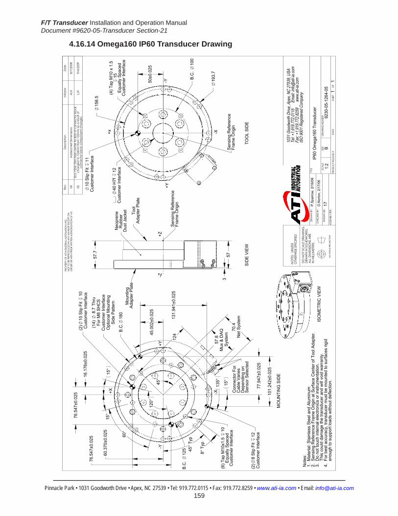
F/T Transducer Installation and Operation ManualDocument #9620-05-Transducer Section-21
Pinnacle Park • 1031 Goodworth Drive • Apex, NC 27539 • Tel: 919.772.0115 • Fax: 919.772.8259 • www.ati-ia.com • Email: [email protected] 159
4.16.14 Omega160 IP60 Transducer Drawing
B.C
. 12
5
15°
15°
60°
120°
124
(2)
10 S
lip F
it 10
Cus
tom
er In
terfa
ce
Side
Pat
tern
Opt
iona
l Mou
ntin
gC
usto
mer
Inte
rface
For M
8 SH
CS
(14)
8
.7 T
hru
B.C
.18
0
(2)
8 Sl
ip F
it 12
Cus
tom
er In
terfa
ce
15°
135°
60.3
70±0
.025
16.1
76±0
.025
76.5
47±0
.025
76.5
47±0
.025
45.0
02±0
.025
77.9
47±0
.025
131.
941±
0.02
5
101.
242±
0.02
5
45° T
yp
8° T
yp
45°
57.8
Mux
& D
AQ
Syst
em
70.4
Net
Sys
tem
+X
-Y
-X
+Y
(6) T
ap M
10x1
.5
10Eq
ually
Spa
ced
Cus
tom
er In
terfa
ceC
onne
ctor
For
C
able
Var
ies
Dep
endi
ng o
nSe
nsor
Sel
ecte
d
57.7
357
Mou
ntin
g A
dapt
er P
late
Neo
pren
eR
ubbe
r D
ust J
acke
t
-Z+Z
Tool
Adap
ter P
late
Sens
ing
Ref
eren
ceFr
ame
Orig
in
B.C
. 10
0
10 S
lip F
it 11
Cus
tom
er In
terfa
ce
50±0
.025
40 H
7f
12C
usto
mer
Inte
rface
156.
5
193.
7
+x -X
-Y+Y
(4) T
ap M
10 x
1.5
15Eq
ually
Spa
ced
Cus
tom
er In
terfa
ce
Sens
ing
Ref
eren
ceFr
ame
Orig
in
Not
es:
1. M
ater
ial:
Stai
nles
s St
eel a
nd A
lum
inum
2. S
ensi
ng R
efer
ence
Fra
me
Orig
in a
t Sur
face
Cen
ter o
f Too
l Ada
pter
.3.
Do
not t
ouch
inte
rnal
ele
ctro
nics
or i
nstru
men
tatio
n.
T
his
coul
d da
mag
e th
e tra
nsdu
cer a
nd w
ill vo
id w
arra
nty.
4. F
or b
est a
ccur
acy,
tran
sduc
er m
ust b
e m
ount
ed to
sur
face
s rig
id
e
noug
h to
sup
port
load
s w
ithou
t def
lect
ion.
ISO
MET
RIC
VIE
W
TOO
L SI
DE
SID
E VI
EW
MO
UN
TIN
G S
IDE
Rev.
Des
crip
tion
Initi
ator
Dat
e
04A
dded
Net
Dim
ensio
ns
ALH
8/7/
2008
05Ec
o 72
55; D
im fr
om c
ente
r to
limit
of c
onne
ctor
blo
ck
chan
ged
to 1
24m
m fr
om 1
32m
m a
s a re
sult
of
conn
ecto
r blo
ck c
ompo
nent
cha
nges
.LJ
H9/
4/20
09
1031
Goo
dwor
th Dr
ive, A
pex,
NC 27
539,
USA
Tel: +
1.919
.772.0
115
Em
ail: in
fo@ati
-ia.co
mFa
x: +1
.919.7
72.82
59
www
.ati-ia
.com
ISO
9001
Reg
ister
ed C
ompa
ny
NO
TES:
UN
LESS
O
THER
WIS
E SP
ECIFI
ED
DO
NO
T SC
ALE
DRA
WIN
G.
DRA
WN
IN S
OLID
WO
RKS.
ALL
DIM
ENSI
ON
S A
RE
IN M
ILLIM
ETER
S.
3rd
AN
GLE
PRO
JEC
TION
DRA
WN
BY:
CHE
CKE
D B
Y:
WEI
GHT
LBS
:
ASS
EMBL
Y RE
F:
P.Sp
arro
w, 2
/16/
06
D.N
orto
n, 2
/17/
06
TITLE SC
ALE
SIZE
DRA
WIN
G N
UMBE
R
PRO
DUC
T REL
EASE
#D
ATE
:SH
EET
O
F
PRO
PERT
Y O
F A
TI IN
DUS
TRIA
L A
UTO
MA
TION
, IN
C.
NO
T TO
BE
REPR
OD
UCED
IN A
NY
MA
NN
ER E
XCEP
T ON
ORD
ER O
R W
ITH P
RIO
R W
RITT
EN A
UTHO
RIZA
TION
OF
ATI.
IP60
Om
ega1
60 T
rans
duce
r
9230
-05-
1264
-05
B1:
21
1
17
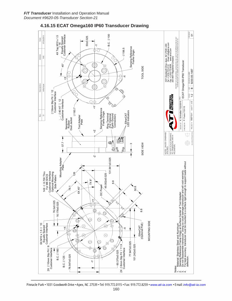
F/T Transducer Installation and Operation ManualDocument #9620-05-Transducer Section-21
Pinnacle Park • 1031 Goodworth Drive • Apex, NC 27539 • Tel: 919.772.0115 • Fax: 919.772.8259 • www.ati-ia.com • Email: [email protected] 160
4.16.15 ECAT Omega160 IP60 Transducer Drawing
3rd
AN
GLE
PRO
JEC
TION
126
78.
1
50.
8
8.8
8.8
6X M
10 x
1.5
1
0E
qual
ly S
pace
dC
usto
mer
Inte
rface
B.C
.12
5
2X
10m
m S
lip F
it8
Cus
tom
er In
terfa
ce
2X
8mm
Slip
Fit
11.9
Cus
tom
er In
terfa
ce
B.C
.18
0
7X
8°
6X
45°
16.
176±
0.02
5
76.
547±
0.02
5
101
.242
±0.0
25
131
.941
±0.0
25
76.
5±0.
025
60.
370±
0.02
5
45.
002±
0.02
5
77.
947±
0.02
5
14X
8
.700
Thr
uFo
r M8
SH
CS
Cus
tom
er In
terfa
ceO
ptio
nal M
ount
ing
Sid
e P
atte
rn
+X
-Y
-X
+Y
Eth
erC
AT
(O
ptio
nal P
oE)
DC
Pow
er
57.7 3
Neo
pren
eR
ubbe
r D
ust J
acke
t
-Z+Z
Sen
sing
Ref
eren
ceFr
ame
Orig
in
Tool
Ada
pter
P
late
Mou
ntin
g A
dapt
er
P
late
Eth
erC
AT
LED
Indi
cato
rs
Rin
g Te
rmin
al
(For
Opt
iona
l E
arth
Gro
und
Con
nect
ion)
B.C
. 10
0
10m
m S
lip F
it 1
2C
usto
mer
Inte
rface
Cus
tom
er In
terfa
ce40
H7
12
45°
50±0
.025
156.
5
19
3.7
+X
-X
-Y+Y
4X T
ap M
10 x
1.5
16E
qual
ly S
pace
dC
usto
mer
Inte
rface
Sen
sing
Ref
eren
ceFr
ame
Orig
in
Not
es: Mat
eria
l: S
tain
less
Ste
el a
nd A
lum
inum
1.S
ensi
ng R
efer
ence
Fra
me
Orig
in a
t Sur
face
Cen
ter o
f Too
l Ada
pter
.2.
Do
not d
isas
sem
ble
trans
duce
r. D
oing
so
coul
d da
mag
e tra
nsdu
cer a
nd w
ill v
oid
war
rant
y.3.
For b
est a
ccur
acy,
tran
sduc
er m
ust b
e m
ount
ed to
a s
urfa
ce ri
gid
enou
gh to
sup
port
load
s w
ithou
t 4.
defle
ctio
n.
TOO
L S
IDE
SID
E V
IEW
MO
UN
TIN
G S
IDE
Rev.
Des
crip
tion
Initi
ator
Dat
e
01In
itial
Issu
eKH
S07
/24/
2015
B1:
21
2RE
VISI
ON
NO
TES:
UN
LESS
OTH
ERW
ISE
SPEC
IFIE
D.
DO
NO
T SC
ALE
DRA
WIN
G.
ALL
DIM
ENSI
ON
S A
RE IN
M
ILLIM
ETER
S.
DRA
WN
BY:
CHE
CKE
D B
Y:
K. S
chna
tter 7
/22/
2015
P. F
usco
7/3
1/15
TITLE SC
ALE
SIZE
DRA
WIN
G N
UMBE
R
PRO
JEC
T #
SHEE
T
O
F 92
30-0
5-14
8715
0713
-101
PRO
PERT
Y O
F A
TI IN
DUS
TRIA
L A
UTO
MA
TION
, IN
C. N
OT
TO B
E RE
PRO
DUC
ED IN
AN
Y M
AN
NER
EXC
EPT
ON
ORD
ER O
R W
ITH P
RIO
R W
RITT
EN A
UTHO
RIZA
TION
OF
ATI.
1031
Goo
dwor
th Dr
ive, A
pex,
NC 27
539,
USA
Tel: +
1.919
.772.0
115
Em
ail: in
fo@ati
-ia.co
mFa
x: +1
.919.7
72.82
59
www
.ati-ia
.com
ISO
9001
Reg
ister
ed C
ompa
ny
ECAT
Om
ega1
60-IP
60 T
rans
duce
r

F/T Transducer Installation and Operation ManualDocument #9620-05-Transducer Section-21
Pinnacle Park • 1031 Goodworth Drive • Apex, NC 27539 • Tel: 919.772.0115 • Fax: 919.772.8259 • www.ati-ia.com • Email: [email protected] 161
3rd
AN
GLE
PRO
JEC
TION
DC
Pow
er C
onne
ctor
3 pi
n M
ale
M8
Eth
erC
AT
Con
nect
or4
pin
Fem
ale
M12
D-C
oded
D-C
oded
ISO
ME
TRIC
VIE
W
Pin
No.
Sig
nal
1V
+3
GN
D4
N/C
Pin
No.
Sig
nal
1TX
+2
RX
+3
TX-
4R
X-
She
llC
onne
ctor
Blo
ck H
ousi
ng
B5:
12
2RE
VISI
ON
NO
TES:
UN
LESS
OTH
ERW
ISE
SPEC
IFIE
D.
DO
NO
T SC
ALE
DRA
WIN
G.
ALL
DIM
ENSI
ON
S A
RE IN
M
ILLIM
ETER
S.
DRA
WN
BY:
CHE
CKE
D B
Y:
K. S
chna
tter 7
/22/
2015
P. F
usco
7/3
1/15
TITLE SC
ALE
SIZE
DRA
WIN
G N
UMBE
R
PRO
JEC
T #
SHEE
T
O
F 92
30-0
5-14
8715
0713
-101
PRO
PERT
Y O
F A
TI IN
DUS
TRIA
L A
UTO
MA
TION
, IN
C. N
OT
TO B
E RE
PRO
DUC
ED IN
AN
Y M
AN
NER
EXC
EPT
ON
ORD
ER O
R W
ITH P
RIO
R W
RITT
EN A
UTHO
RIZA
TION
OF
ATI.
1031
Goo
dwor
th Dr
ive, A
pex,
NC 27
539,
USA
Tel: +
1.919
.772.0
115
Em
ail: in
fo@ati
-ia.co
mFa
x: +1
.919.7
72.82
59
www
.ati-ia
.com
ISO
9001
Reg
ister
ed C
ompa
ny
ECAT
Om
ega1
60-IP
60 T
rans
duce
r
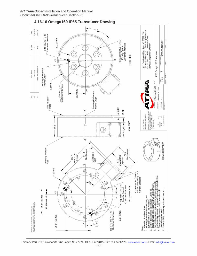
F/T Transducer Installation and Operation ManualDocument #9620-05-Transducer Section-21
Pinnacle Park • 1031 Goodworth Drive • Apex, NC 27539 • Tel: 919.772.0115 • Fax: 919.772.8259 • www.ati-ia.com • Email: [email protected] 162
4.16.16 Omega160 IP65 Transducer Drawing
B.C
. 12
5
120°
165
Cus
tom
er In
terfa
ceEq
ually
Spa
ced
(6) T
ap M
8X1.
25
12
(2)
10 S
lip F
it 10
Cus
tom
er In
terfa
ce
124.
5M
ux &
DAQ
Syst
em
63.3
Mux
& D
AQSy
stem
76.5
47±0
.025
76.5
47±0
.025
16.1
76±0
.025 15°
45°
15°
117.
5N
et S
yste
m
70.5
Net
Sys
tem
Mem
bran
e Ve
nt
Not
es:
1. M
ater
ial:
Stai
nles
s St
eel
2. S
ensi
ng R
efer
ence
Fra
me
Orig
in a
t
sur
face
cen
ter o
f Too
l Ada
pter
.3.
Do
not d
isas
sem
ble
trans
duce
r. D
oing
so
c
ould
dam
age
trans
duce
r and
will
void
war
rant
y.4.
For
bes
t acc
urac
y, tr
ansd
ucer
mus
t be
mou
nted
to
s
urfa
ces
rigid
eno
ugh
to s
uppo
rt lo
ads
with
out d
efle
ctio
n.
5. C
able
mus
t be
conn
ecte
d to
tran
sduc
er to
mai
ntai
n pr
oper
sea
l.6.
Cab
le is
IP65
rate
d on
ly a
t tra
nsdu
cer e
nd.
Con
nect
or fo
r Cab
leVa
ries
Dep
endi
ng o
nSe
nsor
Sel
ecte
d
6.22
15.2
444
.2065
.91
Sens
ing
Ref
eren
ceFr
ame
Orig
in
-Z+Z
Mou
ntin
g Ad
apte
r Pl
ate
Tool
Ada
pter
Pl
ate
B.C
.10
0
Cus
tom
er In
terfa
ceEq
ually
Spa
ced
(4) T
ap M
10X1
.5
15
40 H
7 20
Cus
tom
er In
terfa
ce
Cus
tom
er In
terfa
ce10
Slip
Fit
16
50±0
.025
45°
157.
5
Sens
ing
Ref
eren
ceFr
ame
Orig
in
ISO
MET
RIC
VIE
W
MO
UN
TIN
G S
IDE
SID
E VI
EWTO
OL
SID
E
+Y
-X
-Y+Y
-Y
+X -X
+X
Rev.
Des
crip
tion
Initi
ator
Dat
e
01In
itial
Issu
ePS
2/16
/200
6
02A
dded
Net
Dim
ensio
nsA
LH8/
8/20
08
1031
Goo
dwor
th Dr
ive, A
pex,
NC 27
539,
USA
Tel: +
1.919
.772.0
115
Em
ail: in
fo@ati
-ia.co
mFa
x: +1
.919.7
72.82
59
www
.ati-ia
.com
ISO
9001
Reg
ister
ed C
ompa
ny
NO
TES:
UN
LESS
O
THER
WIS
E SP
ECIFI
ED
DO
NO
T SC
ALE
DRA
WIN
G.
DRA
WN
IN S
OLID
WO
RKS.
ALL
DIM
ENSI
ON
S A
RE IN
MILL
IMET
ERS.
3rd
AN
GLE
PRO
JEC
TION
DRA
WN
BY:
CHE
CKE
D B
Y:
WEI
GHT
LBS
:
ASS
EMBL
Y RE
F:
P.Sp
arro
w, 2
/16/
06
D.N
orto
n, 2
/17/
06
TITLE SC
ALE
SIZE
DRA
WIN
G N
UMBE
R
PRO
DUC
T REL
EASE
#D
ATE
:SH
EET
O
F
PRO
PERT
Y O
F A
TI IN
DUS
TRIA
L A
UTO
MA
TION
, IN
C.
NO
T TO
BE
REPR
OD
UCED
IN A
NY
MA
NN
ER E
XCEP
T ON
ORD
ER O
R W
ITH P
RIO
R W
RITT
EN A
UTHO
RIZA
TION
OF
ATI.
IP65
Om
ega1
60 T
rans
duce
r
9230
-05-
1269
-02
B1:
1.5
11
16

F/T Transducer Installation and Operation ManualDocument #9620-05-Transducer Section-21
Pinnacle Park • 1031 Goodworth Drive • Apex, NC 27539 • Tel: 919.772.0115 • Fax: 919.772.8259 • www.ati-ia.com • Email: [email protected] 163
4.16.17 Omega160IP68TransducerDrawing
15°
60°
Typ
165
124.
5
(2)
10 H
7,
10C
usto
mer
Inte
rface
Cus
tom
er In
terfa
ce
(6) T
AP M
8X1.
25
12.
7Eq
ually
Spa
ced
B.C
. 12
5
60.3
70±0
.012
76.5
47±0
.012
76.5
47±0
.012
16.1
76±0
.012
61
120°
[ref]
15°
[ref]
NO
TES:
1. M
ATER
IAL:
Sta
inle
ss S
teel
2. S
ensi
ng R
efer
ence
fram
e or
igin
at
s
urfa
ce c
ente
r of t
ool a
dapt
er.
3. D
o no
t dis
asse
mbl
e tra
nsdu
cer.
Doi
ng s
o
cou
ld d
amag
e tra
nsdu
cer a
nd v
oid
war
rant
y.4.
For
bes
t acc
urac
y, tr
ansd
ucer
mus
t be
m
ount
ed to
sur
face
s rig
id e
noug
h to
sup
port
lo
ads
with
out d
efle
ctio
n.
5. C
able
mus
t be
conn
ecte
d to
Tra
nsdu
cer t
o
mai
ntai
n pr
oper
sea
l.6.
Cab
le is
onl
y IP
68 ra
ted
at T
rans
duce
r End
.
Tra
nsdu
cer i
s IP
68 ra
ted
in fr
eshw
ater
env
ironm
ent
a
t a d
epth
of u
p to
10
met
ers.
Con
nect
or fo
r Cab
leVa
ries
Dep
endi
ng o
nSe
nsor
Sel
ecte
d
65.9
44.2
15.26.
2157.
5
Sens
ing
Ref
eren
ceFr
ame
Orig
in
-Z+Z
40 H
7,
20C
usto
mer
Inte
rface
10 H
7,
16C
usto
mer
Inte
rface
Cus
tom
er In
terfa
ce
(4) T
AP M
10X1
.5
15.
2Eq
ually
Spa
ced
B.C
. 10
0
45°
Typ
49.9
990.
012
Sens
ing
Ref
eren
ceFr
ame
Orig
in
ISO
MET
RIC
VIE
W
MO
UN
TIN
G S
IDE
SID
E VI
EWTO
OL
SID
E
+Y
-X
-Y+Y
-Y
+X -X
+X
Rev.
Des
crip
tion
Initi
ator
Dat
e
02Up
date
d m
odel
link.
PS3/
4/20
06
1031
Goo
dwor
th Dr
ive, A
pex,
NC 27
539,
USA
Tel: +
1.919
.772.0
115
Em
ail: in
fo@ati
-ia.co
mFa
x: +1
.919.7
72.82
59
www
.ati-ia
.com
ISO
9001
Reg
ister
ed C
ompa
ny
3rd
AN
GLE
PRO
JEC
TION
ASS
EMBL
Y RE
F:
TITLE SC
ALE
SIZE
DRA
WIN
G N
UMBE
R
PRO
DUC
T REL
EASE
#D
ATE
:SH
EET
O
F
IP68
-10m
OM
EGA1
60 T
rans
duce
r
9230
-05-
1274
-02
B1:
1.5
11
NO
TES:
UN
LESS
OTH
ERW
ISE
SPEC
IFIED
3rd
AN
GLE
PRO
JEC
TION
ASS
EMBL
Y RE
F:
TITLE SC
ALE
SIZE
DRA
WIN
G N
UMBE
R
PRO
DUC
T REL
EASE
#D
ATE
:SH
EET
O
F
IP68
-10m
OM
EGA1
60 T
rans
duce
r
B1:
1.5
11
1031
Goo
dwor
th Dr
ive, A
pex,
NC 27
539,
USA
Tel: +
1.919
.772.0
115
Em
ail: in
fo@ati
-ia.co
mFa
x: +1
.919.7
72.82
59
www
.ati-ia
.com
ISO
9001
Reg
ister
ed C
ompa
ny
NO
TES:
UN
LESS
OTH
ERW
ISE
SPEC
IFIED
DO
NO
T SC
ALE
DRA
WIN
G.
DRA
WN
IN S
OLID
WO
RKS.
ALL
DIM
ENSI
ON
S A
RE IN
MILL
IMET
ERS.
3rd
AN
GLE
PRO
JEC
TION
DRA
WN
BY:
CHE
CKE
D B
Y:
WEI
GHT
LBS
:
ASS
EMBL
Y RE
F:
P.Sp
arro
w, 2
/16/
06
D. N
orto
n, 2
/17/
06
TITLE SC
ALE
SIZE
DRA
WIN
G N
UMBE
R
PRO
DUC
T REL
EASE
#D
ATE
:SH
EET
O
F
IP68
-10m
OM
EGA1
60 T
rans
duce
r
9230
-05-
1274
-02
B1:
1.5
11
16
PRO
PERT
Y O
F A
TI IN
DUS
TRIA
L A
UTO
MA
TION
, IN
C.
NO
T TO
BE
REPR
OD
UCED
IN A
NY
MA
NN
ER E
XCEP
T ON
ORD
ER O
R W
ITH P
RIO
R W
RITT
EN A
UTHO
RIZA
TION
OF
ATI.

F/T Transducer Installation and Operation ManualDocument #9620-05-Transducer Section-21
Pinnacle Park • 1031 Goodworth Drive • Apex, NC 27539 • Tel: 919.772.0115 • Fax: 919.772.8259 • www.ati-ia.com • Email: [email protected] 164
4.17 Omega190Specifications(IncludesIP60/IP65/IP68Versions)4.17.1 Omega190 Physical Properties
Table 4.95—Omega190 Physical PropertiesSingle-Axis Overload (US)StandardUnits (SI)MetricUnitsFxy ±8000 lbf ±36000 NFz ±25000 lbf ±110000 NTxy ±60000 lbf-in ±6800 NmTz ±60000 lbf-in ±6800 NmStiffness(Calculated)X-axis&Y-axisforces(Kx,Ky) 1.4x10⁶ lb/in 2.4x10⁸ N/mZ-axisforce(Kz) 2.1x10⁶ lb/in 3.6x10⁸ N/mX-axis&Y-axistorque(Ktx,Kty) 1.4x10⁷ lbf-in/rad 1.5x10⁶ Nm/radZ-axistorque(Ktz) 2.8x10⁷ lbf-in/rad 3.2x10⁶ Nm/radResonant FrequencyFx, Fy, Tz N/A N/AFz, Tx, Ty N/A N/A PhysicalSpecificationsWeight1 14 lb 6.35 kg
Diameter1 7.48 in 190 mm
Height1 2.2 in 55.9 mmNote: 1. Specifications include standard interface plates.
4.17.2 Omega190 IP60 Physical PropertiesTable 4.96—Omega190 IP60 Physical Properties
Single-Axis Overload (US)StandardUnits (SI)MetricUnitsFxy ±8000 lbf ±36000 NFz ±25000 lbf ±110000 NTxy ±60000 lbf-in ±6800 NmTz ±60000 lbf-in ±6800 NmStiffness(Calculated)X-axis&Y-axisforces(Kx,Ky) 1.4x10⁶ lb/in 2.4x10⁸ N/mZ-axisforce(Kz) 2.1x10⁶ lb/in 3.6x10⁸ N/mX-axis&Y-axistorque(Ktx,Kty) 1.4x10⁷ lbf-in/rad 1.5x10⁶ Nm/radZ-axistorque(Ktz) 2.8x10⁷ lbf-in/rad 3.2x10⁶ Nm/radResonant FrequencyFx, Fy, Tz 1200 Hz 1200 HzFz, Tx, Ty 1200 Hz 1200 HzPhysicalSpecificationsWeight1 31 lb 14.1 kg
Diameter1 9.37 in 238 mm
Height1 2.9 in 73.7 mmNote: 1. Specifications include standard interface plates.
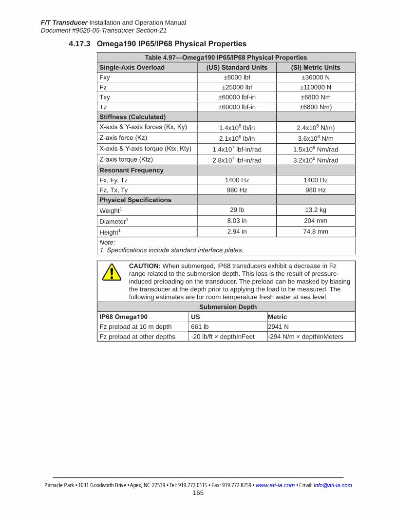
F/T Transducer Installation and Operation ManualDocument #9620-05-Transducer Section-21
Pinnacle Park • 1031 Goodworth Drive • Apex, NC 27539 • Tel: 919.772.0115 • Fax: 919.772.8259 • www.ati-ia.com • Email: [email protected] 165
4.17.3 Omega190IP65/IP68PhysicalPropertiesTable 4.97—Omega190IP65/IP68PhysicalProperties
Single-Axis Overload (US)StandardUnits (SI)MetricUnitsFxy ±8000 lbf ±36000 NFz ±25000 lbf ±110000 NTxy ±60000 lbf-in ±6800 NmTz ±60000 lbf-in ±6800Nm)Stiffness(Calculated)X-axis&Y-axisforces(Kx,Ky) 1.4x10⁶ lb/in 2.4x10⁸N/m)Z-axisforce(Kz) 2.1x10⁶ lb/in 3.6x10⁸ N/mX-axis&Y-axistorque(Ktx,Kty) 1.4x10⁷ lbf-in/rad 1.5x10⁶ Nm/radZ-axistorque(Ktz) 2.8x10⁷ lbf-in/rad 3.2x10⁶ Nm/radResonant FrequencyFx, Fy, Tz 1400 Hz 1400 HzFz, Tx, Ty 980 Hz 980 HzPhysicalSpecificationsWeight1 29 lb 13.2 kg
Diameter1 8.03 in 204 mm
Height1 2.94 in 74.8 mm
Note: 1. Specifications include standard interface plates.
CAUTION: When submerged, IP68 transducers exhibit a decrease in Fz range related to the submersion depth. This loss is the result of pressure-induced preloading on the transducer. The preload can be masked by biasing the transducer at the depth prior to applying the load to be measured. The following estimates are for room temperature fresh water at sea level.
Submersion DepthIP68Omega190 US MetricFz preload at 10 m depth 661 lb 2941 NFz preload at other depths -20 lb/ft × depthInFeet -294 N/m × depthInMeters
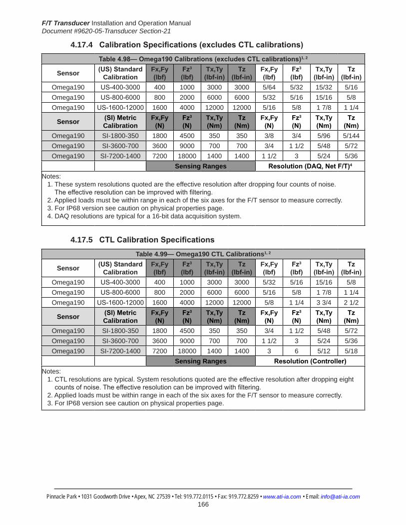
F/T Transducer Installation and Operation ManualDocument #9620-05-Transducer Section-21
Pinnacle Park • 1031 Goodworth Drive • Apex, NC 27539 • Tel: 919.772.0115 • Fax: 919.772.8259 • www.ati-ia.com • Email: [email protected] 166
4.17.4 CalibrationSpecifications(excludesCTLcalibrations)
Table4.98—Omega190Calibrations(excludesCTLcalibrations)1, 2
Sensor (US)Standard Calibration
Fx,Fy (lbf)
Fz3 (lbf)
Tx,Ty (lbf-in)
Tz (lbf-in)
Fx,Fy (lbf)
Fz3 (lbf)
Tx,Ty (lbf-in)
Tz (lbf-in)
Omega190 US-400-3000 400 1000 3000 3000 5/64 5/32 15/32 5/16Omega190 US-800-6000 800 2000 6000 6000 5/32 5/16 15/16 5/8Omega190 US-1600-12000 1600 4000 12000 12000 5/16 5/8 1 7/8 1 1/4
Sensor (SI)Metric Calibration
Fx,Fy (N)
Fz3 (N)
Tx,Ty (Nm)
Tz (Nm)
Fx,Fy (N)
Fz3 (N)
Tx,Ty (Nm)
Tz (Nm)
Omega190 SI-1800-350 1800 4500 350 350 3/8 3/4 5/96 5/144Omega190 SI-3600-700 3600 9000 700 700 3/4 1 1/2 5/48 5/72Omega190 SI-7200-1400 7200 18000 1400 1400 1 1/2 3 5/24 5/36
Sensing Ranges Resolution(DAQ,NetF/T)4
Notes: 1. These system resolutions quoted are the effective resolution after dropping four counts of noise. Theeffectiveresolutioncanbeimprovedwithfiltering. 2. Applied loads must be within range in each of the six axes for the F/T sensor to measure correctly. 3. For IP68 version see caution on physical properties page. 4. DAQ resolutions are typical for a 16-bit data acquisition system.
4.17.5 CTLCalibrationSpecifications
Table 4.99— Omega190 CTL Calibrations1, 2
Sensor (US)Standard Calibration
Fx,Fy (lbf)
Fz3 (lbf)
Tx,Ty (lbf-in)
Tz (lbf-in)
Fx,Fy (lbf)
Fz3 (lbf)
Tx,Ty (lbf-in)
Tz (lbf-in)
Omega190 US-400-3000 400 1000 3000 3000 5/32 5/16 15/16 5/8Omega190 US-800-6000 800 2000 6000 6000 5/16 5/8 1 7/8 1 1/4Omega190 US-1600-12000 1600 4000 12000 12000 5/8 1 1/4 3 3/4 2 1/2
Sensor (SI)Metric Calibration
Fx,Fy (N)
Fz3 (N)
Tx,Ty (Nm)
Tz (Nm)
Fx,Fy (N)
Fz3 (N)
Tx,Ty (Nm)
Tz (Nm)
Omega190 SI-1800-350 1800 4500 350 350 3/4 1 1/2 5/48 5/72Omega190 SI-3600-700 3600 9000 700 700 1 1/2 3 5/24 5/36Omega190 SI-7200-1400 7200 18000 1400 1400 3 6 5/12 5/18
Sensing Ranges Resolution(Controller)Notes: 1. CTL resolutions are typical. System resolutions quoted are the effective resolution after dropping eight countsofnoise.Theeffectiveresolutioncanbeimprovedwithfiltering. 2. Applied loads must be within range in each of the six axes for the F/T sensor to measure correctly. 3. For IP68 version see caution on physical properties page.
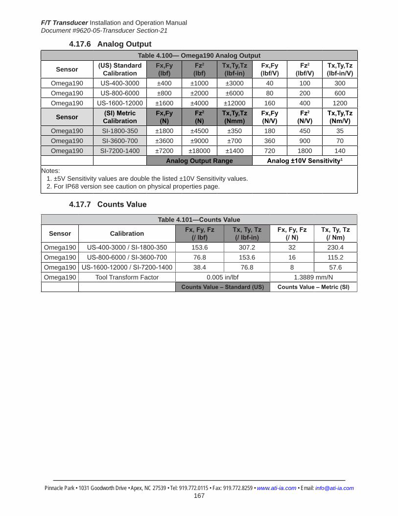
F/T Transducer Installation and Operation ManualDocument #9620-05-Transducer Section-21
Pinnacle Park • 1031 Goodworth Drive • Apex, NC 27539 • Tel: 919.772.0115 • Fax: 919.772.8259 • www.ati-ia.com • Email: [email protected] 167
4.17.6 Analog OutputTable 4.100— Omega190 Analog Output
Sensor (US)Standard Calibration
Fx,Fy (lbf)
Fz2 (lbf)
Tx,Ty,Tz (lbf-in)
Fx,Fy (lbf/V)
Fz2 (lbf/V)
Tx,Ty,Tz (lbf-in/V)
Omega190 US-400-3000 ±400 ±1000 ±3000 40 100 300Omega190 US-800-6000 ±800 ±2000 ±6000 80 200 600Omega190 US-1600-12000 ±1600 ±4000 ±12000 160 400 1200
Sensor (SI)Metric Calibration
Fx,Fy (N)
Fz2 (N)
Tx,Ty,Tz (Nmm)
Fx,Fy (N/V)
Fz2 (N/V)
Tx,Ty,Tz (Nm/V)
Omega190 SI-1800-350 ±1800 ±4500 ±350 180 450 35Omega190 SI-3600-700 ±3600 ±9000 ±700 360 900 70Omega190 SI-7200-1400 ±7200 ±18000 ±1400 720 1800 140
Analog Output Range Analog±10VSensitivity1
Notes: 1. ±5V Sensitivity values are double the listed ±10V Sensitivity values. 2. For IP68 version see caution on physical properties page.
4.17.7 CountsValue
Table 4.101—CountsValue
Sensor Calibration Fx,Fy,Fz (/lbf)
Tx,Ty,Tz (/lbf-in)
Fx,Fy,Fz (/N)
Tx,Ty,Tz (/Nm)
Omega190 US-400-3000/SI-1800-350 153.6 307.2 32 230.4Omega190 US-800-6000/SI-3600-700 76.8 153.6 16 115.2Omega190 US-1600-12000/SI-7200-1400 38.4 76.8 8 57.6Omega190 Tool Transform Factor 0.005 in/lbf 1.3889 mm/N
CountsValue–Standard(US) CountsValue–Metric(SI)

F/T Transducer Installation and Operation ManualDocument #9620-05-Transducer Section-21
Pinnacle Park • 1031 Goodworth Drive • Apex, NC 27539 • Tel: 919.772.0115 • Fax: 919.772.8259 • www.ati-ia.com • Email: [email protected] 168
4.17.8 Omega190(USCalibrationComplexLoading) (IncludesIP60/IP65/IP68)1
US-400-3000 US-800-6000 US-1600-12000
Note: 1. For IP68 version see caution on physical properties page.

F/T Transducer Installation and Operation ManualDocument #9620-05-Transducer Section-21
Pinnacle Park • 1031 Goodworth Drive • Apex, NC 27539 • Tel: 919.772.0115 • Fax: 919.772.8259 • www.ati-ia.com • Email: [email protected] 169
4.17.9 Omega190(SICalibrationComplexLoading) (IncludesIP60/IP65/IP68)1
SI-1800-350 SI-3600-700 SI-7200-1400
Note: 1. For IP68 version see caution on physical properties page.

F/T Transducer Installation and Operation ManualDocument #9620-05-Transducer Section-21
Pinnacle Park • 1031 Goodworth Drive • Apex, NC 27539 • Tel: 919.772.0115 • Fax: 919.772.8259 • www.ati-ia.com • Email: [email protected] 170
4.17.10 Omega190DAQ/NetTransducerDrawing
3rd
AN
GLE
PRO
JEC
TION
ISO
MET
RIC
VIE
W
2X
10 S
lip F
it8
Cus
tom
er In
terfa
ce(S
ee N
ote
2)
70±
0.02
5
119
.497
±0.0
25
49.
497±
0.02
5
38.6
DAQ
Sys
tem
22.
5°
45°
112.
8D
AQ S
yste
m 4
5°
135
°
113.
4N
et S
yste
m
44.8
Net
Sys
tem
8X T
ap M
8 x
1.25
8
B.C
. 14
0Eq
ually
Spa
ced
Cus
tom
er In
terfa
ce(S
ee N
ote
2)
+X -X
+Y-Y
55.
9
19
0
14.7
DAQ
Sys
tem
19.1
Net
Sys
tem+Z
-Z
Sens
ing
Ref
eren
ceFr
ame
Orig
in
Tool
Adap
ter
Plat
e
Mou
ntin
gAd
apte
rPl
ate
SID
E VI
EW
75.
197±
0.02
5
60°
10 S
lip F
it 15
Cus
tom
er In
terfa
ce(S
ee N
ote
2)
57.1
7557
.125
8C
usto
mer
Inte
rface
(See
Not
e 2)
6X M
12 x
1.7
5 15
B.C
15
0.4
Equa
lly S
pace
dC
usto
mer
Inte
rface
(See
Not
e 2)
Sens
ing
Ref
eren
ceFr
ame
Orig
in
-Y+Y
+X -X
MO
UN
TIN
G S
IDE
TOO
L SI
DE
Not
es: M
ater
ial:
Har
dene
d St
ainl
ess
Stee
l and
Alu
min
um1.
DO N
OT
EXCE
ED IN
TERF
ACE
DEPT
H, M
AY C
AUSE
DAM
AGE.
2.D
o no
t dis
asse
mbl
e tra
nsdu
cer.
Doi
ng s
o co
uld
dam
age
trans
duce
r and
will
3.vo
id th
e w
arra
nty.
For b
est a
ccur
acy
trans
duce
r mus
t be
mou
nted
to s
urfa
ce ri
gid
enou
gh4.
to s
uppo
rt lo
ads
with
out d
efle
ctio
n.
Rev
.D
escr
iptio
nIn
itiat
orD
ate
15EC
O95
95: U
pdat
e do
wel
pin
loca
tions
.LT
F3/
20/2
012
B1:
21
1RE
VISIO
N
NO
TES:
UN
LESS
OTH
ERW
ISE
SPEC
IFIED
.
DO
NO
T SC
ALE
DRA
WIN
G.
ALL
DIM
ENSI
ON
S A
RE IN
M
ILLIM
ETER
S.
DRA
WN
BY:
CHE
CKE
D B
Y:
B.D
iges
o, 3
/8/0
0
D. N
orto
n 7/
15/0
5
TITLE SC
ALE
SIZE
DRA
WIN
G N
UMBE
R
PRO
JEC
T #SH
EET
O
F 92
30-0
5-10
9515
PRO
PERT
Y O
F A
TI IN
DUS
TRIA
L A
UTO
MA
TION
, IN
C. N
OT T
O B
E RE
PRO
DUC
ED IN
AN
Y M
AN
NER
EXC
EPT O
N O
RDER
OR
WITH
PRI
OR
WRI
TTEN
AUT
HORI
ZATIO
N O
F A
TI.
1031
Goo
dwor
th Dr
ive, A
pex,
NC 27
539,
USA
Tel: +
1.919
.772.0
115
Em
ail: in
fo@ati
-ia.co
mFa
x: +1
.919.7
72.82
59
www
.ati-ia
.com
ISO
9001
Reg
ister
ed C
ompa
ny
Om
ega1
90 D
AQ/N
et T
rans
duce
r

F/T Transducer Installation and Operation ManualDocument #9620-05-Transducer Section-21
Pinnacle Park • 1031 Goodworth Drive • Apex, NC 27539 • Tel: 919.772.0115 • Fax: 919.772.8259 • www.ati-ia.com • Email: [email protected] 171
4.17.11 Omega190 IP60 Transducer Drawing
B.C
.14
0
70.0
02±0
.025
119.
502±
0.02
5
49.4
99±0
.025
(2)
10 S
lip F
it 11
Cus
tom
er In
terfa
ce
135°
22.5
°
141.
5
45°
28.4
70±0
.025
123.
733±
0.02
5
161.
252±
0.02
510
6.25
2±0.
025
135° 15
°57
.8M
ux &
DAQ
Sy
stem
45°
Typ
Side
Pat
tern
Opt
iona
l Mou
ntin
gC
usto
mer
Inte
rface
For M
8 SH
CS
(7)
8.7
Thr
u
(2)
8 Sl
ip F
it 11
Cus
tom
er In
terfa
ce
B.C
. 22
0
70.4
Net
Sys
tem
TOO
L SI
DE
SID
E VI
EW
MO
UN
TIN
G S
IDE
ISO
MET
RIC
VIE
W
Not
es:
1. M
ater
ial:
Stai
nles
s St
eel a
nd A
lum
inum
2. D
o no
t tou
ch in
tern
al e
lect
roni
cs o
r ins
trum
enta
tion.
Thi
s co
uld
dam
age
the
trans
duce
r and
will
void
war
rant
y.3.
Sen
sing
Ref
eren
ce F
ram
e O
rigin
at s
urfa
ce c
ente
r of T
ool A
dapt
er.
4. F
or b
est a
ccur
acy,
tran
sduc
er m
ust b
e m
ount
ed to
sur
face
s rig
id
eno
ugh
to s
uppo
rt lo
ads
with
out d
efle
ctio
n.
(8) T
ap M
8 x
1.25
12
Equa
lly S
pace
dC
usto
mer
Inte
rface
+X
-X
+Y-Y
Con
nect
or F
or C
able
Varie
s D
epen
ding
on
Sens
or S
elec
ted
74.3
21.8
8.1
62.1
Sens
ing
Ref
eren
ceFr
ame
Orig
in
Tool
Ad
apte
r Pla
te
Neo
pren
eR
ubbe
r D
ust J
acke
t
Mou
ntin
g Ad
apte
r Pla
te
+Z-Z
10 S
lip F
it 12
Cus
tom
er In
terfa
ce
75.1
97±0
.025
B.C
.15
0
57.1
7557
.125
12
Cus
tom
er In
terfa
ce
238
190
Sens
ing
Ref
eren
ceFr
ame
Orig
in
(6) T
ap M
12x1
.75
16Eq
ually
Spa
ced
Cus
tom
er In
terfa
ce+X -X
-Y+Y
Rev.
Des
crip
tion
Initi
ator
Dat
e
03A
dded
Net
Dim
ensio
nsA
LH8/
7/20
08
04Ec
o 72
55; D
im fr
om c
ente
r to
limit
of c
onne
ctor
blo
ck
chan
ged
to 1
41.5
mm
as a
resu
lt of
con
nect
or b
lock
co
mpo
nent
cha
nges
.LJ
H9/
4/20
09
1031
Goo
dwor
th Dr
ive, A
pex,
NC 27
539,
USA
Tel: +
1.919
.772.0
115
Em
ail: in
fo@ati
-ia.co
mFa
x: +1
.919.7
72.82
59
www
.ati-ia
.com
ISO
9001
Reg
ister
ed C
ompa
ny
NO
TES:
UN
LESS
O
THER
WIS
E SP
ECIFI
ED
DO
NO
T SC
ALE
DRA
WIN
G.
DRA
WN
IN S
OLID
WO
RKS.
ALL
DIM
ENSI
ON
S A
RE
IN M
ILLIM
ETER
S.
3rd
AN
GLE
PRO
JEC
TION
DRA
WN
BY:
CHE
CKE
D B
Y:
WEI
GHT
LBS
:
ASS
EMBL
Y RE
F:
P.Sp
arro
w, 2
/16/
06
D.N
orto
n, 2
/17/
06
TITLE SC
ALE
SIZE
DRA
WIN
G N
UMBE
R
PRO
DUC
T REL
EASE
#D
ATE
:SH
EET
O
F
PRO
PERT
Y O
F A
TI IN
DUS
TRIA
L A
UTO
MA
TION
, IN
C.
NO
T TO
BE
REPR
OD
UCED
IN A
NY
MA
NN
ER E
XCEP
T ON
ORD
ER O
R W
ITH P
RIO
R W
RITT
EN A
UTHO
RIZA
TION
OF
ATI.
IP60
Om
ega1
90 T
rans
duce
r
9230
-05-
1265
-04
B1:
21
1
31

F/T Transducer Installation and Operation ManualDocument #9620-05-Transducer Section-21
Pinnacle Park • 1031 Goodworth Drive • Apex, NC 27539 • Tel: 919.772.0115 • Fax: 919.772.8259 • www.ati-ia.com • Email: [email protected] 172
4.17.12 Omega190 IP65 Transducer Drawing
3rd
AN
GLE
PRO
JEC
TION
ISO
MET
RIC
VIE
W
Cus
tom
er In
terfa
ceEq
ually
Spa
ced
12X
Tap
M8X
1.25
12
.5
204
142.
9M
ux a
nd D
AQ
Syst
em
2X10
Slip
Fit
11C
usto
mer
Inte
rface
135°
70.0
02±0
.025
119.
502±
0.02
5
49.4
99±0
.025
B.C
. 14
0
90.0
°
135.
9N
et S
yste
m
63.3
Mux
and
DAQ
Sy
stem
70.5
Net
Sys
tem
Mem
bran
e Ve
nt
-X+X
-Y+Y
Con
nect
or F
or C
able
Varie
s D
epen
ding
on
Sens
or S
elec
ted
74.8
2.4
44.2
28.1
-Z
Sens
ing
Ref
eren
ceFr
ame
Orig
in
Mou
ntin
g Ad
apte
r Pl
ate
Tool
Ada
pter
Plat
e
+Z
B.C
.15
0.39
10 S
lip F
it 16
Cus
tom
er In
terfa
ce 60°
57.1
7557
.125
24
Cus
tom
er In
terfa
ce
75.1
97±0
.025
195.
6
6X T
ap M
12x1
.75
12Eq
ually
Spa
ced
Cus
tom
er In
terfa
ce
Sens
ing
Ref
eren
ceFr
ame
Orig
in
MO
UN
TIN
G S
IDE
SID
E VI
EWTO
OL
SID
E
+Y-Y
+X -X
Not
es: M
ater
ial:
Stai
nles
s St
eel
1.Se
nsin
g R
efer
ence
Fra
me
Orig
in a
t sur
face
cen
ter o
f 2.
Tool
Ada
pter
.D
o no
t dis
asse
mbl
e tra
nsdu
cer.
Doi
ng s
o co
uld
dam
age
3.tra
nsdu
cer a
nd w
ill vo
id w
arra
nty.
For b
est a
ccur
acy,
tran
sduc
er m
ust b
e m
ount
ed to
sur
face
s 4.
rigid
eno
ugh
to s
uppo
rt lo
ads
with
out d
efle
ctio
n.
Cab
le m
ust b
e co
nnec
ted
to tr
ansd
ucer
to m
aint
ain
prop
er s
eal.
5.C
able
is IP
65 ra
ted
only
at t
rans
duce
r end
.6.
Rev.
Des
crip
tion
Initi
ator
Dat
e
05EC
9074
: Cor
rect
ed tr
ansd
ucer
thic
knes
sRK
C10
/27/
2011
B1:
21
1RE
VISIO
N
NO
TES:
UN
LESS
OTH
ERW
ISE
SPEC
IFIED
.
DO
NO
T SC
ALE
DRA
WIN
G.
ALL
DIM
ENSI
ON
S A
RE IN
M
ILLIM
ETER
S.
DRA
WN
BY:
CHE
CKE
D B
Y:
P.Sp
arro
w, 2
/16/
06
D. N
orto
n, 2
/17/
06
TITLE SC
ALE
SIZE
DRA
WIN
G N
UMBE
R
PRO
JEC
T #SH
EET
O
F 92
30-0
5-12
70-
05
PRO
PERT
Y O
F A
TI IN
DUS
TRIA
L A
UTO
MA
TION
, IN
C. N
OT T
O B
E RE
PRO
DUC
ED IN
AN
Y M
AN
NER
EXC
EPT O
N O
RDER
OR
WITH
PRI
OR
WRI
TTEN
AUT
HORI
ZATIO
N O
F A
TI.
1031
Goo
dwor
th Dr
ive, A
pex,
NC 27
539,
USA
Tel: +
1.919
.772.0
115
Em
ail: in
fo@ati
-ia.co
mFa
x: +1
.919.7
72.82
59
www
.ati-ia
.com
ISO
9001
Reg
ister
ed C
ompa
ny
IP65
Om
ega1
90 T
rans
duce
r
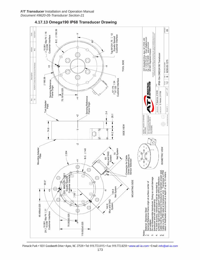
F/T Transducer Installation and Operation ManualDocument #9620-05-Transducer Section-21
Pinnacle Park • 1031 Goodworth Drive • Apex, NC 27539 • Tel: 919.772.0115 • Fax: 919.772.8259 • www.ati-ia.com • Email: [email protected] 173
4.17.13 Omega190IP68TransducerDrawing
3rd
AN
GLE
PRO
JEC
TION
ISO
MET
RIC
VIE
W
70.0
02±0
.025
119.
502±
0.02
5
142.
9M
ux a
nd D
AQSy
stem
B.C
. 14
0
204
2X10
.061
10.0
36 S
lip F
it 11
Cus
tom
er In
terfa
ce
63M
ux a
nd D
AQSy
stem
135.
9N
et S
yste
m70
Net
Sys
tem
90.
0°
49.
499±
0.02
5
12X
M8X
1.25
12
.5Eq
ually
Spa
ced
Cus
tom
er In
terfa
ce
135
°
Con
nect
or fo
r Cab
leVa
ries
Dep
endi
ng o
nSe
nsor
Sel
ecte
d
+X -X
+Y-Y
MO
UN
TIN
G S
IDE
44.2
28.12.
4
74.8
-Z
Sens
ing
Ref
eren
ceFr
ame
Orig
in
+Z
SID
E VI
EW
Tool
Ada
pter
Pl
ate
Mou
ntin
g Ad
apte
rPl
ate
75.1
97±0
.025
10.0
6110
.036
Slip
Fit
16C
usto
mer
Inte
rface
Cus
tom
er In
terfa
ceEq
ually
Spa
ced
Tap
M12
X1.7
5
12
60°
B.C
. 15
0.39
57.1
7557
.125
24
C
usto
mer
Inte
rface
19
5.58
Sens
ing
Ref
eren
ceFr
ame
Orig
in+X
+Y
-X
-Y
TOO
L SI
DE
Not
es: Mat
eria
l: St
ainl
ess
Stee
l1.
Sens
ing
Ref
eren
ce fr
ame
orig
in a
t sur
face
cen
ter o
f 2.
tool
ada
pter
.D
o no
t dis
asse
mbl
e tra
nsdu
cer.
Doi
ng s
o co
uld
dam
age
3.tra
nsdu
cer a
nd w
ill vo
id w
arra
nty.
For b
est a
ccur
acy,
tran
sduc
er m
ust b
e m
ount
ed to
4.
surfa
ces
rigid
eno
ugh
to s
uppo
rt lo
ads
with
out d
efle
ctio
n.
Cab
le m
ust b
e co
nnec
ted
to tr
ansd
ucer
to m
aint
ain
prop
er s
eal.
5.C
able
is o
nly
IP68
rate
d at
tran
sduc
er e
nd.
Tran
sduc
er is
IP68
6.
rate
d in
fres
hwat
er e
nviro
nmen
t at a
dep
th o
f up
to 1
0 m
eter
s.
Rev.
Des
crip
tion
Initi
ator
Dat
e
05EC
9074
: Cor
rect
ed tr
ansd
ucer
thic
knes
sRK
C10
/27/
2011
B1:
21
1RE
VISIO
N
NO
TES:
UN
LESS
OTH
ERW
ISE
SPEC
IFIED
.
DO
NO
T SC
ALE
DRA
WIN
G.
ALL
DIM
ENSI
ON
S A
RE IN
M
ILLIM
ETER
S.
DRA
WN
BY:
CHE
CKE
D B
Y:
P.Sp
arro
w, 2
/16/
06
D. N
orto
n, 2
/17/
06
TITLE SC
ALE
SIZE
DRA
WIN
G N
UMBE
R
PRO
JEC
T #SH
EET
O
F 92
30-0
5-12
75-
05
PRO
PERT
Y O
F A
TI IN
DUS
TRIA
L A
UTO
MA
TION
, IN
C. N
OT T
O B
E RE
PRO
DUC
ED IN
AN
Y M
AN
NER
EXC
EPT O
N O
RDER
OR
WITH
PRI
OR
WRI
TTEN
AUT
HORI
ZATIO
N O
F A
TI.
1031
Goo
dwor
th Dr
ive, A
pex,
NC 27
539,
USA
Tel: +
1.919
.772.0
115
Em
ail: in
fo@ati
-ia.co
mFa
x: +1
.919.7
72.82
59
www
.ati-ia
.com
ISO
9001
Reg
ister
ed C
ompa
ny
IP68
-10m
OM
EGA1
90 T
rans
duce
r
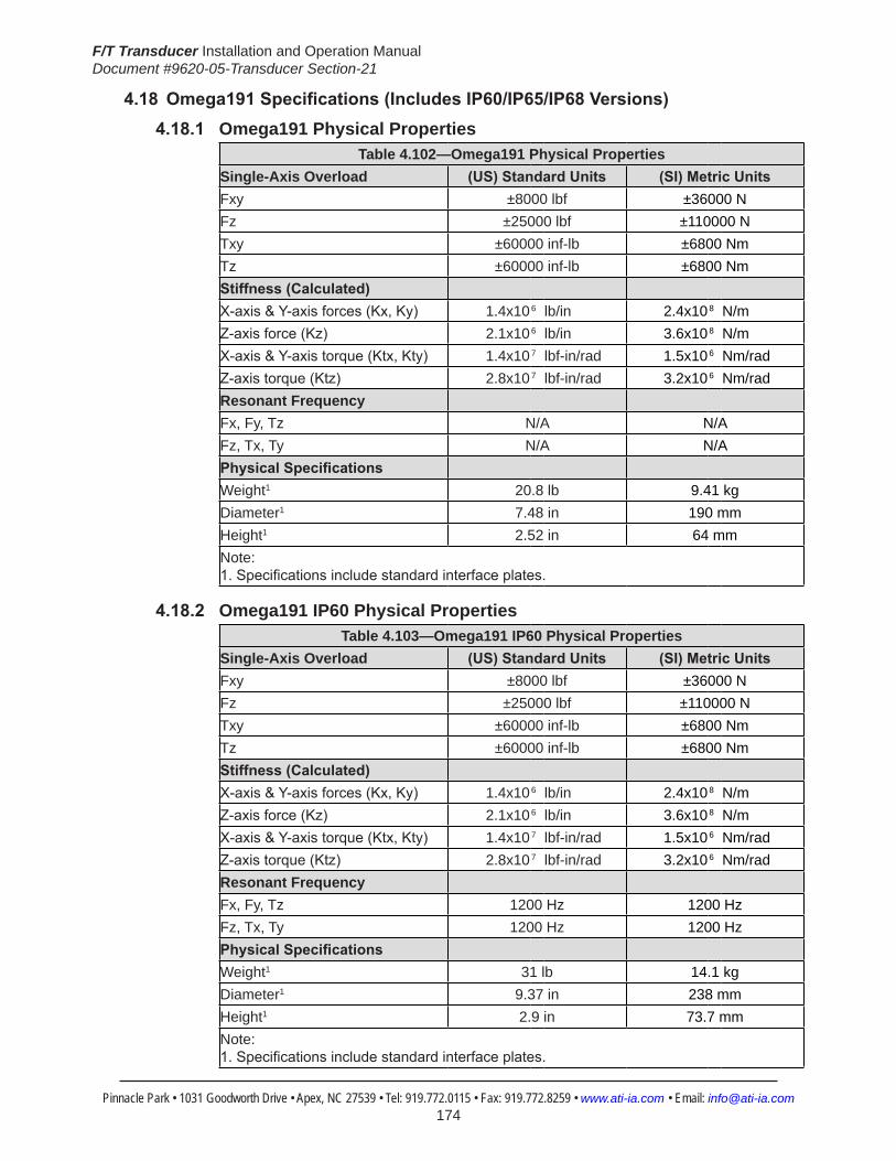
F/T Transducer Installation and Operation ManualDocument #9620-05-Transducer Section-21
Pinnacle Park • 1031 Goodworth Drive • Apex, NC 27539 • Tel: 919.772.0115 • Fax: 919.772.8259 • www.ati-ia.com • Email: [email protected] 174
4.18Omega191Specifications(IncludesIP60/IP65/IP68Versions)4.18.1 Omega191 Physical Properties
Table 4.102—Omega191 Physical PropertiesSingle-Axis Overload (US)StandardUnits (SI)MetricUnitsFxy ±8000 lbf ±36000 NFz ±25000 lbf ±110000 NTxy ±60000 inf-lb ±6800 NmTz ±60000 inf-lb ±6800 NmStiffness(Calculated) X-axis&Y-axisforces(Kx,Ky) 1.4x10⁶ lb/in 2.4x10⁸ N/m Z-axisforce(Kz) 2.1x10⁶ lb/in 3.6x10⁸ N/m X-axis&Y-axistorque(Ktx,Kty) 1.4x10⁷ lbf-in/rad 1.5x10⁶ Nm/rad Z-axistorque(Ktz) 2.8x10⁷ lbf-in/rad 3.2x10⁶ Nm/rad Resonant Frequency Fx, Fy, Tz N/A N/AFz, Tx, Ty N/A N/APhysicalSpecifications Weight1 20.8 lb 9.41 kgDiameter1 7.48 in 190 mmHeight1 2.52 in 64 mmNote: 1.Specificationsincludestandardinterfaceplates.
4.18.2 Omega191 IP60 Physical PropertiesTable 4.103—Omega191 IP60 Physical Properties
Single-Axis Overload (US)StandardUnits (SI)MetricUnitsFxy ±8000 lbf ±36000 NFz ±25000 lbf ±110000 NTxy ±60000 inf-lb ±6800 NmTz ±60000 inf-lb ±6800 NmStiffness(Calculated) X-axis&Y-axisforces(Kx,Ky) 1.4x10⁶ lb/in 2.4x10⁸ N/m Z-axisforce(Kz) 2.1x10⁶ lb/in 3.6x10⁸ N/m X-axis&Y-axistorque(Ktx,Kty) 1.4x10⁷ lbf-in/rad 1.5x10⁶ Nm/rad Z-axistorque(Ktz) 2.8x10⁷ lbf-in/rad 3.2x10⁶ Nm/rad Resonant Frequency Fx, Fy, Tz 1200 Hz 1200 HzFz, Tx, Ty 1200 Hz 1200 HzPhysicalSpecifications Weight1 31 lb 14.1 kgDiameter1 9.37 in 238 mmHeight1 2.9 in 73.7 mmNote: 1.Specificationsincludestandardinterfaceplates.

F/T Transducer Installation and Operation ManualDocument #9620-05-Transducer Section-21
Pinnacle Park • 1031 Goodworth Drive • Apex, NC 27539 • Tel: 919.772.0115 • Fax: 919.772.8259 • www.ati-ia.com • Email: [email protected] 175
4.18.3 Omega191IP65/IP68PhysicalPropertiesTable 4.104—Omega191IP65/IP68PhysicalProperties
Single-Axis Overload (US)StandardUnits (SI)MetricUnitsFxy ±8000 lbf ±36000 NFz ±25000 lbf ±110000 NTxy ±60000 inf-lb ±6800 NmTz ±60000 inf-lb ±6800 NmStiffness(Calculated) X-axis&Y-axisforces(Kx,Ky) 1.4x10⁶ lb/in 2.4x10⁸ N/m Z-axisforce(Kz) 2.1x10⁶ lb/in 3.6x10⁸ N/m X-axis&Y-axistorque(Ktx,Kty) 1.4x10⁷ lbf-in/rad 1.5x10⁶ Nm/rad Z-axistorque(Ktz) 2.8x10⁷ lbf-in/rad 3.2x10⁶ Nm/rad Resonant Frequency Fx, Fy, Tz 1400 Hz 1400 HzFz, Tx, Ty 980 Hz 980 HzPhysicalSpecifications Weight1 29 lb 13.2 kgDiameter1 8.03 in 204 mmHeight1 2.94 in 74.8 mmNote: 1.Specificationsincludestandardinterfaceplates.
CAUTION: When submerged, IP68 transducers exhibit a decrease in Fz range related to the submersion depth. This loss is the result of pressure-induced preloading on the transducer. The preload can be masked by biasing the transducer at the depth prior to applying the load to be measured. The following estimates are for room temperature fresh water at sea level.
Submersion DepthIP68Omega191 US MetricFz preload at 10 m depth 661 lb 2941 NFz preload at other depths -20 lb/ft × depthInFeet -294 N/m × depthInMeters

F/T Transducer Installation and Operation ManualDocument #9620-05-Transducer Section-21
Pinnacle Park • 1031 Goodworth Drive • Apex, NC 27539 • Tel: 919.772.0115 • Fax: 919.772.8259 • www.ati-ia.com • Email: [email protected] 176
4.18.4 CalibrationSpecifications(excludesCTLcalibrations)
Table 4.105—Omega191Calibrations(excludesCTLcalibrations)1, 2
Sensor (US)Standard Calibration
Fx,Fy (lbf)
Fz3 (lbf)
Tx,Ty (lbf-in)
Tz (lbf-in)
Fx,Fy (lbf)
Fz3 (lbf)
Tx,Ty (lbf-in)
Tz (lbf-in)
Omega191 US-400-3000 400 1000 3000 3000 5/64 5/32 15/32 5/16Omega191 US-800-6000 800 2000 6000 6000 5/32 5/16 15/16 5/8Omega191 US-1600-12000 1600 4000 12000 12000 5/16 5/8 1 7/8 1 1/4
Sensor (SI)Metric Calibration
Fx,Fy (N)
Fz3 (N)
Tx,Ty (Nm)
Tz (Nm)
Fx,Fy (N)
Fz3 (N)
Tx,Ty (Nm)
Tz (Nm)
Omega191 SI-1800-350 1800 4500 350 350 3/8 3/4 5/96 5/144Omega191 SI-3600-700 3600 9000 700 700 3/4 1 1/2 5/48 5/72Omega191 SI-7200-1400 7200 18000 1400 1400 1 1/2 3 5/24 5/36
Sensing Ranges Resolution(DAQ,NetF/T)4
Notes: 1. These system resolutions quoted are the effective resolution after dropping four counts of noise. Theeffectiveresolutioncanbeimprovedwithfiltering. 2. Applied loads must be within range in each of the six axes for the F/T sensor to measure correctly. 3. For IP68 version see caution on physical properties page. 4. DAQ resolutions are typical for a 16-bit data acquisition system.
4.18.5 CTLCalibrationSpecifications
Table 4.106— Omega191 CTL Calibrations1, 2
Sensor (US)Standard Calibration
Fx,Fy (lbf)
Fz3 (lbf)
Tx,Ty (lbf-in)
Tz (lbf-in)
Fx,Fy (lbf)
Fz3 (lbf)
Tx,Ty (lbf-in)
Tz (lbf-in)
Omega191 US-400-3000 400 1000 3000 3000 5/32 5/16 15/16 5/8Omega191 US-800-6000 800 2000 6000 6000 5/16 5/8 1 7/8 1 1/4Omega191 US-1600-12000 1600 4000 12000 12000 5/8 1 1/4 3 3/4 2 1/2
Sensor (SI)Metric Calibration
Fx,Fy (N)
Fz3 (N)
Tx,Ty (Nm)
Tz (Nm)
Fx,Fy (N)
Fz3 (N)
Tx,Ty (Nm)
Tz (Nm)
Omega191 SI-1800-350 1800 4500 350 350 3/4 1 1/2 5/48 5/72Omega191 SI-3600-700 3600 9000 700 700 1 1/2 3 5/24 5/36Omega191 SI-7200-1400 7200 18000 1400 1400 3 6 5/12 5/18
Sensing Ranges Resolution(Controller)Notes: 1. CTL resolutions are typical. System resolutions quoted are the effective resolution after dropping eight countsofnoise.Theeffectiveresolutioncanbeimprovedwithfiltering. 2. Applied loads must be within range in each of the six axes for the F/T sensor to measure correctly. 3. For IP68 version see caution on physical properties page.

F/T Transducer Installation and Operation ManualDocument #9620-05-Transducer Section-21
Pinnacle Park • 1031 Goodworth Drive • Apex, NC 27539 • Tel: 919.772.0115 • Fax: 919.772.8259 • www.ati-ia.com • Email: [email protected] 177
4.18.6 Analog Output
Table 4.107— Omega191 Analog Output
Sensor (US)Standard Calibration
Fx,Fy (lbf)
Fz2 (lbf)
Tx,Ty,Tz (lbf-in)
Fx,Fy (lbf/V)
Fz2 (lbf/V)
Tx,Ty,Tz (lbf-in/V)
Omega191 US-400-3000 ±400 ±1000 ±3000 40 100 300Omega191 US-800-6000 ±800 ±2000 ±6000 80 200 600Omega191 US-1600-12000 ±1600 ±4000 ±12000 160 400 1200
Sensor (SI)Metric Calibration
Fx,Fy (N)
Fz2 (N)
Tx,Ty,Tz (Nmm)
Fx,Fy (N/V)
Fz2 (N/V)
Tx,Ty,Tz (Nm/V)
Omega191 SI-1800-350 ±1800 ±4500 ±350 180 450 35Omega191 SI-3600-700 ±3600 ±9000 ±700 360 900 70Omega191 SI-7200-1400 ±7200 ±18000 ±1400 720 1800 140
Analog Output Range Analog±10VSensitivity1
Notes: 1. ±5V Sensitivity values are double the listed ±10V Sensitivity values. 2. For IP68 version see caution on physical properties page.
4.18.7 CountsValue
Table4.108—CountsValue
Sensor Calibration Fx,Fy,Fz (/lbf)
Tx,Ty,Tz (/lbf-in)
Fx,Fy,Fz (/N)
Tx,Ty,Tz (/Nm)
Omega191 US-400-3000/SI-1800-350 153.6 307.2 32 230.4Omega191 US-800-6000/SI-3600-700 76.8 153.6 16 115.2Omega191 US-1600-12000/SI-7200-1400 38.4 76.8 8 57.6Omega191 Tool Transform Factor 0.005 in/lbf 1.3889 mm/N
CountsValue–Standard(US) CountsValue–Metric(SI)

F/T Transducer Installation and Operation ManualDocument #9620-05-Transducer Section-21
Pinnacle Park • 1031 Goodworth Drive • Apex, NC 27539 • Tel: 919.772.0115 • Fax: 919.772.8259 • www.ati-ia.com • Email: [email protected] 178
4.18.8 Omega191(USCalibrationComplexLoading) (IncludesIP60/IP65/IP68)1
HelpOmega191
US-400-3000 US-800-6000 US-1600-12000
Note: 1. For IP68 version see caution on physical properties page.
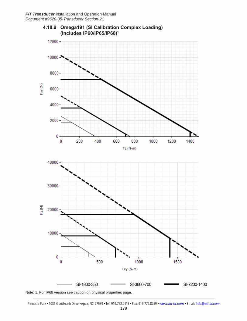
F/T Transducer Installation and Operation ManualDocument #9620-05-Transducer Section-21
Pinnacle Park • 1031 Goodworth Drive • Apex, NC 27539 • Tel: 919.772.0115 • Fax: 919.772.8259 • www.ati-ia.com • Email: [email protected] 179
4.18.9 Omega191(SICalibrationComplexLoading) (IncludesIP60/IP65/IP68)1
HelpOmega191
SI-1800-350 SI-3600-700 SI-7200-1400
Note: 1. For IP68 version see caution on physical properties page.

F/T Transducer Installation and Operation ManualDocument #9620-05-Transducer Section-21
Pinnacle Park • 1031 Goodworth Drive • Apex, NC 27539 • Tel: 919.772.0115 • Fax: 919.772.8259 • www.ati-ia.com • Email: [email protected] 180
4.18.10Omega191DAQ/NetTransducerDrawing
3rd
AN
GLE
PRO
JEC
TION
75.
197±
0.02
5
2X
30°
8X T
ap M
12X1
.75
16C
usto
mer
Inte
rface
(See
Not
e 2)
10 S
lip F
it 1
5C
usto
mer
Inte
rface
2X
30°
30°
3
0°
B.C
.15
0.4
57.1
7557
.125
10
1.0
x 45
Cha
mfe
rC
usto
mer
Inte
rface
(See
Not
e 2)
Sens
ing
Ref
eren
ceFr
ame
Orig
in
TOO
L SI
DE
-X
+Y-Y
+X 6
4
19
0
23.4
Net
Sys
tem
19D
AQ S
yste
m
Sens
ing
Ref
eren
ceFr
ame
Orig
in
Tool
Adap
ter
Plat
e
Mou
ntin
gAd
apte
rPl
ate
SID
E VI
EW
+Z-Z
49.
497±
0.02
5
70±
0.02
5
119
.497
±0.0
25
2X
10 S
lip F
it 10
Cus
tom
er In
terfa
ce
113.
4N
et S
yste
m
44.8
Net
Sys
tem
38.6
DAQ
Sys
tem
12X
Tap
M8X
1.25
12
Cus
tom
er In
terfa
ce(S
ee N
ote
2)
22.5
°Ty
p. 2
2.5°
B.C
. 14
0
45°
11
2.8
DAQ
Sys
tem
MO
UN
TIN
G S
IDE
-X+X
-Y+Y
ISO
MET
RIC
VIE
W
Not
es:
Mat
eria
l: H
arde
ned
Stee
l and
Sta
inle
ss S
teel
1.D
O N
OT
EXC
EED
INTE
RFA
CE
DEP
TH, M
AY
CA
USE
DA
MA
GE
2.D
o no
t dis
asse
mbl
e tra
nsdu
cer.
Doi
ng s
o co
uld
dam
age
trans
duce
r and
will
3.vo
id th
e w
arra
nty.
For b
est a
ccur
acy
trans
duce
r mus
t be
mou
nted
to a
sur
face
rigi
d en
ough
to
4.su
ppor
t loa
ds w
ithou
t def
lect
ion.
Rev.
Des
crip
tion
Initi
ator
Dat
e
03EC
O 1
4230
; Add
ed c
ham
fer c
all o
ut a
nd u
pdat
ed ta
pped
ho
le c
all o
uts t
o st
anda
rd.
SZJ
7/13
/201
6
B1:
21
1RE
VISIO
N
NO
TES:
UN
LESS
OTH
ERW
ISE
SPEC
IFIED
.
DO
NO
T SC
ALE
DRA
WIN
G.
ALL
DIM
ENSI
ON
S A
RE IN
M
ILLIM
ETER
S.
DRA
WN
BY:
CHE
CKE
D B
Y:
L. F
ishe
r, 2/
27/1
4
P. F
usco
, 2/2
8/20
14
TITLE SC
ALE
SIZE
DRA
WIN
G N
UMBE
R
PRO
JEC
T #SH
EET
O
F 92
30-0
5-14
6414
0217
-303
PRO
PERT
Y O
F A
TI IN
DUS
TRIA
L A
UTO
MA
TION
, IN
C. N
OT T
O B
E RE
PRO
DUC
ED IN
AN
Y M
AN
NER
EXC
EPT O
N O
RDER
OR
WITH
PRI
OR
WRI
TTEN
AUT
HORI
ZATIO
N O
F A
TI.
1031
Goo
dwor
th Dr
ive, A
pex,
NC 27
539,
USA
Tel: +
1.919
.772.0
115
Em
ail: in
fo@ati
-ia.co
mFa
x: +1
.919.7
72.82
59
www
.ati-ia
.com
ISO
9001
Reg
ister
ed C
ompa
ny
Om
ega1
91 D
AQ/N
et T
rans
duce
r

F/T Transducer Installation and Operation ManualDocument #9620-05-Transducer Section-21
Pinnacle Park • 1031 Goodworth Drive • Apex, NC 27539 • Tel: 919.772.0115 • Fax: 919.772.8259 • www.ati-ia.com • Email: [email protected] 181
4.18.11Omega191 IP60 Transducer Drawing
3rd
AN
GLE
PRO
JEC
TION
70.0
02±0
.025
119.
502±
0.02
549.4
99±0
.025
2X10
Slip
Fit
11C
usto
mer
Inte
rface
141.
5
28.4
70±0
.025
123.
733±
0.02
5
161.
252±
0.02
5
106.
252±
0.02
5
45°
Typ
Side
Pat
tern
Opt
iona
l Mou
ntin
gC
usto
mer
Inte
rface
For M
8 SH
CS
7X
8.7
Thr
u
2X
8 Sl
ip F
it 11
Cus
tom
er In
terfa
ce
B.C
. 22
0 57.8
Mux
& D
AQSy
stem
4X
22.5
°
22.
5°
22.
5°
B.C
. 14
0
4X
22.5
°
70.4
Net
Sys
tem
45°
TOO
L SI
DE
SID
E VI
EWM
OU
NTI
NG
SID
E
12X
Tap
M8
x 1.
25
12C
usto
mer
Inte
rface
+X -X
+Y-Y
Con
nect
or F
or C
able
Varie
s D
epen
ding
on
Sens
or S
elec
ted
74.3
22.9 8.1
62.1
Sens
ing
Ref
eren
ceFr
ame
Orig
in
Tool
Ad
apte
r Pla
te
Neo
pren
eR
ubbe
r D
ust J
acke
tM
ount
ing
Adap
ter P
late
+Z-Z
10 S
lip F
it 12
Cus
tom
er In
terfa
ce
75.1
97±0
.025
57.1
7557
.125
12
Cus
tom
er In
terfa
ce
238
190
30°
3
0°
2X
30°
2X
30°
B.C
. 15
0.4
Sens
ing
Ref
eren
ceFr
ame
Orig
in
8X T
ap M
12x1
.75
16C
usto
mer
Inte
rface
+X -X
-Y+Y
ISO
MET
RIC
VIE
W
Not
es: Mat
eria
l: H
arde
ned
Stee
l, St
ainl
ess
Stee
l and
Alu
min
um1.
Sens
ing
Ref
eren
ce F
ram
e O
rigin
at s
urfa
ce c
ente
r of T
ool A
dapt
er.
2.D
o no
t dis
asse
mbl
e tra
nsdu
cer.
Doi
ng s
o co
uld
dam
age
trans
duce
r 3.
and
will
void
war
rant
y.Fo
r bes
t acc
urac
y, tr
ansd
ucer
mus
t be
mou
nted
to a
sur
face
rigi
d 4.
enou
gh to
sup
port
load
s w
ithou
t def
lect
ion.
Rev.
Des
crip
tion
Initi
ator
Dat
e
01Re
leas
eLT
F7/
29/2
014
B1:
2.5
11
REVI
SION
NO
TES:
UN
LESS
OTH
ERW
ISE
SPEC
IFIED
.
DO
NO
T SC
ALE
DRA
WIN
G.
ALL
DIM
ENSI
ON
S A
RE IN
M
ILLIM
ETER
S.
DRA
WN
BY:
CHE
CKE
D B
Y:
L. F
ishe
r, 5/
30/2
014
A. P
ongo
r, 6/
9/20
14
TITLE SC
ALE
SIZE
DRA
WIN
G N
UMBE
R
PRO
JEC
T #SH
EET
O
F 92
30-0
5-14
70-
01
PRO
PERT
Y O
F A
TI IN
DUS
TRIA
L A
UTO
MA
TION
, IN
C. N
OT T
O B
E RE
PRO
DUC
ED IN
AN
Y M
AN
NER
EXC
EPT O
N O
RDER
OR
WITH
PRI
OR
WRI
TTEN
AUT
HORI
ZATIO
N O
F A
TI.
1031
Goo
dwor
th Dr
ive, A
pex,
NC 27
539,
USA
Tel: +
1.919
.772.0
115
Em
ail: in
fo@ati
-ia.co
mFa
x: +1
.919.7
72.82
59
www
.ati-ia
.com
ISO
9001
Reg
ister
ed C
ompa
ny
IP60
Om
ega1
91 T
rans
duce
r

F/T Transducer Installation and Operation ManualDocument #9620-05-Transducer Section-21
Pinnacle Park • 1031 Goodworth Drive • Apex, NC 27539 • Tel: 919.772.0115 • Fax: 919.772.8259 • www.ati-ia.com • Email: [email protected] 182
4.18.12Omega191 IP65 Transducer Drawing
3rd
AN
GLE
PRO
JEC
TION
ISO
MET
RIC
VIE
W
70.0
02±0
.025
119.
502±
0.02
5
142.
9M
ux a
nd D
AQSy
stem
204
63M
ux a
nd D
AQSy
stem
135.
9N
et S
yste
m
70.7
Net
Sys
tem
49.
500±
0.02
5
5X
22.5
° 5
X 22
.5°
22.
5°
22.
5°
B.C
. 14
0
Con
nect
or fo
r Cab
leVa
ries
Dep
endi
ng o
nSe
nsor
Sel
ecte
d
+X
-X
+Y-Y
MO
UN
TIN
G S
IDE
2X
10 S
lip F
it 1
1C
usto
mer
Inte
rface
12X
Tap
M8
X 1.
25
12
Cus
tom
er In
terfa
ce
44.5
27.92.
4
74.8
-Z
Sens
ing
Ref
eren
ceFr
ame
Orig
in
+Z
SID
E VI
EW
Tool
Ada
pter
Pl
ate
Mou
ntin
g Ad
apte
rPl
ate
75.1
97±0
.025
57.1
7557
.125
2
0C
usto
mer
Inte
rface
B.C
. 15
0.4
2X
30°
2X
30°
30°
3
0°
Sens
ing
Ref
eren
ceFr
ame
Orig
in
+X
+Y
-X
-Y
TOO
L SI
DE
8X T
ap M
12 X
1.7
5 1
2C
usto
mer
Inte
rface
10 S
lip F
it 1
6C
usto
mer
Inte
rface
Not
es: Mat
eria
l: St
ainl
ess
Stee
l1.
Sens
ing
Ref
eren
ce F
ram
e O
rigin
at s
urfa
ce c
ente
r of T
ool
2.Ad
apte
r.D
o no
t dis
asse
mbl
e tra
nsdu
cer.
Doi
ng s
o co
uld
dam
age
3.tra
nsdu
cer a
nd w
ill vo
id w
arra
nty.
For b
est a
ccur
acy,
tran
sduc
er m
ust b
e m
ount
ed to
a s
urfa
ce
4.rig
id e
noug
h to
sup
port
load
s w
ithou
t def
lect
ion.
C
able
mus
t be
conn
ecte
d to
tran
sduc
er to
mai
ntai
n pr
oper
5.
seal
.C
able
is o
nly
IP68
rate
d on
ly a
t tra
nsdu
cer e
nd.
Tran
sduc
er
6.is
IP68
rate
d in
fres
hwat
er e
nviro
nmen
t at a
dep
th o
f up
to
10 m
eter
s.
Rev.
Des
crip
tion
Initi
ator
Dat
e
B1:
21
1RE
VISIO
N
NO
TES:
UN
LESS
OTH
ERW
ISE
SPEC
IFIED
.
DO
NO
T SC
ALE
DRA
WIN
G.
ALL
DIM
ENSI
ON
S A
RE IN
M
ILLIM
ETER
S.
DRA
WN
BY:
CHE
CKE
D B
Y:
L. F
ishe
r, 7/
29/2
014
E. B
radf
ord,
7/3
0/20
14
TITLE SC
ALE
SIZE
DRA
WIN
G N
UMBE
R
PRO
JEC
T #SH
EET
O
F 92
30-0
5-14
7114
0627
-101
PRO
PERT
Y O
F A
TI IN
DUS
TRIA
L A
UTO
MA
TION
, IN
C. N
OT T
O B
E RE
PRO
DUC
ED IN
AN
Y M
AN
NER
EXC
EPT O
N O
RDER
OR
WITH
PRI
OR
WRI
TTEN
AUT
HORI
ZATIO
N O
F A
TI.
1031
Goo
dwor
th Dr
ive, A
pex,
NC 27
539,
USA
Tel: +
1.919
.772.0
115
Em
ail: in
fo@ati
-ia.co
mFa
x: +1
.919.7
72.82
59
www
.ati-ia
.com
ISO
9001
Reg
ister
ed C
ompa
ny
IP65
Om
ega1
91 T
rans
duce
r
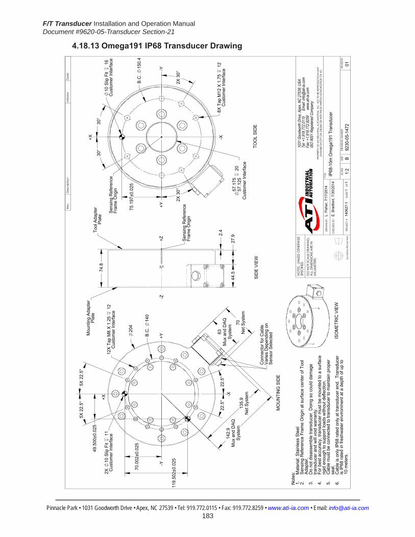
F/T Transducer Installation and Operation ManualDocument #9620-05-Transducer Section-21
Pinnacle Park • 1031 Goodworth Drive • Apex, NC 27539 • Tel: 919.772.0115 • Fax: 919.772.8259 • www.ati-ia.com • Email: [email protected] 183
4.18.13Omega191IP68TransducerDrawing
3rd
AN
GLE
PRO
JEC
TION
ISO
MET
RIC
VIE
W
70.0
02±0
.025
119.
502±
0.02
5
142.
9M
ux a
nd D
AQSy
stem
204
63M
ux a
nd D
AQSy
stem
135.
9N
et S
yste
m
70N
et S
yste
m
49.
500±
0.02
5
5X
22.5
° 5
X 22
.5°
22.
5°
22.
5°
B.C
. 14
0
Con
nect
or fo
r Cab
leVa
ries
Dep
endi
ng o
nSe
nsor
Sel
ecte
d
+X
-X
+Y-Y
MO
UN
TIN
G S
IDE
2X
10 S
lip F
it 1
1C
usto
mer
Inte
rface
12X
Tap
M8
X 1.
25
12
Cus
tom
er In
terfa
ce
44.5
27.92.
4
74.8
-Z
Sens
ing
Ref
eren
ceFr
ame
Orig
in
+Z
SID
E VI
EW
Tool
Ada
pter
Pl
ate
Mou
ntin
g Ad
apte
rPl
ate
75.1
97±0
.025
57.1
7557
.125
2
0C
usto
mer
Inte
rface
B.C
. 15
0.4
2X
30°
2X
30°
30°
3
0°
Sens
ing
Ref
eren
ceFr
ame
Orig
in
+X
+Y
-X
-Y
TOO
L SI
DE
8X T
ap M
12 X
1.7
5 1
2C
usto
mer
Inte
rface
10 S
lip F
it 1
6C
usto
mer
Inte
rface
Not
es: Mat
eria
l: St
ainl
ess
Stee
l1.
Sens
ing
Ref
eren
ce F
ram
e O
rigin
at s
urfa
ce c
ente
r of T
ool
2.Ad
apte
r.D
o no
t dis
asse
mbl
e tra
nsdu
cer.
Doi
ng s
o co
uld
dam
age
3.tra
nsdu
cer a
nd w
ill vo
id w
arra
nty.
For b
est a
ccur
acy,
tran
sduc
er m
ust b
e m
ount
ed to
a s
urfa
ce
4.rig
id e
noug
h to
sup
port
load
s w
ithou
t def
lect
ion.
C
able
mus
t be
conn
ecte
d to
tran
sduc
er to
mai
ntai
n pr
oper
5.
seal
.C
able
is o
nly
IP68
rate
d on
ly a
t tra
nsdu
cer e
nd.
Tran
sduc
er
6.is
IP68
rate
d in
fres
hwat
er e
nviro
nmen
t at a
dep
th o
f up
to
10 m
eter
s.
Rev.
Des
crip
tion
Initi
ator
Dat
e
B1:
21
1RE
VISIO
N
NO
TES:
UN
LESS
OTH
ERW
ISE
SPEC
IFIED
.
DO
NO
T SC
ALE
DRA
WIN
G.
ALL
DIM
ENSI
ON
S A
RE IN
M
ILLIM
ETER
S.
DRA
WN
BY:
CHE
CKE
D B
Y:
L. F
ishe
r, 7/
17/2
014
E. B
radf
ord,
7/3
0/20
14
TITLE SC
ALE
SIZE
DRA
WIN
G N
UMBE
R
PRO
JEC
T #SH
EET
O
F 92
30-0
5-14
7214
0627
-101
PRO
PERT
Y O
F A
TI IN
DUS
TRIA
L A
UTO
MA
TION
, IN
C. N
OT T
O B
E RE
PRO
DUC
ED IN
AN
Y M
AN
NER
EXC
EPT O
N O
RDER
OR
WITH
PRI
OR
WRI
TTEN
AUT
HORI
ZATIO
N O
F A
TI.
1031
Goo
dwor
th Dr
ive, A
pex,
NC 27
539,
USA
Tel: +
1.919
.772.0
115
Em
ail: in
fo@ati
-ia.co
mFa
x: +1
.919.7
72.82
59
www
.ati-ia
.com
ISO
9001
Reg
ister
ed C
ompa
ny
IP68
-10m
Om
ega1
91 T
rans
duce
r
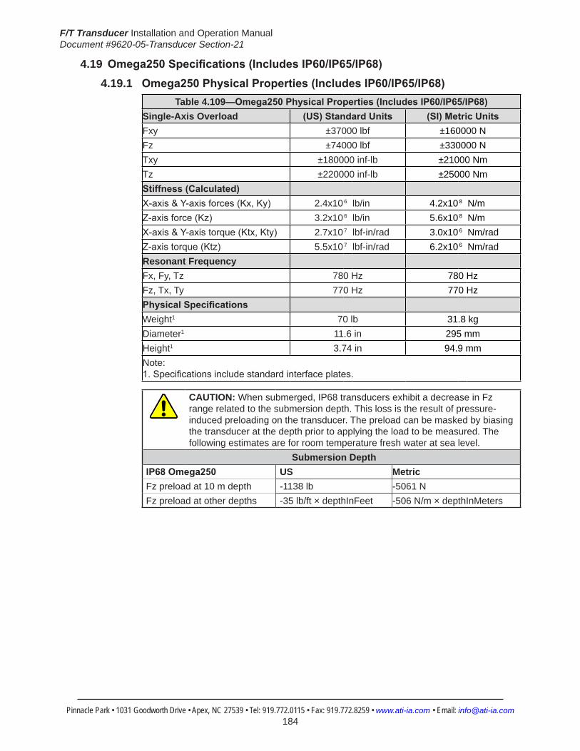
F/T Transducer Installation and Operation ManualDocument #9620-05-Transducer Section-21
Pinnacle Park • 1031 Goodworth Drive • Apex, NC 27539 • Tel: 919.772.0115 • Fax: 919.772.8259 • www.ati-ia.com • Email: [email protected] 184
4.19 Omega250Specifications(IncludesIP60/IP65/IP68)4.19.1 Omega250PhysicalProperties(IncludesIP60/IP65/IP68)
Table 4.109—Omega250PhysicalProperties(IncludesIP60/IP65/IP68)Single-Axis Overload (US)StandardUnits (SI)MetricUnitsFxy ±37000 lbf ±160000 NFz ±74000 lbf ±330000 NTxy ±180000 inf-lb ±21000 NmTz ±220000 inf-lb ±25000 NmStiffness(Calculated) X-axis&Y-axisforces(Kx,Ky) 2.4x10⁶ lb/in 4.2x10⁸ N/m Z-axisforce(Kz) 3.2x10⁶ lb/in 5.6x10⁸ N/m X-axis&Y-axistorque(Ktx,Kty) 2.7x10⁷ lbf-in/rad 3.0x10⁶ Nm/rad Z-axistorque(Ktz) 5.5x10⁷ lbf-in/rad 6.2x10⁶ Nm/rad Resonant Frequency Fx, Fy, Tz 780 Hz 780 HzFz, Tx, Ty 770 Hz 770 HzPhysicalSpecifications Weight1 70 lb 31.8 kgDiameter1 11.6 in 295 mmHeight1 3.74 in 94.9 mmNote: 1.Specificationsincludestandardinterfaceplates.
CAUTION: When submerged, IP68 transducers exhibit a decrease in Fz range related to the submersion depth. This loss is the result of pressure-induced preloading on the transducer. The preload can be masked by biasing the transducer at the depth prior to applying the load to be measured. The following estimates are for room temperature fresh water at sea level.
Submersion DepthIP68Omega250 US MetricFz preload at 10 m depth -1138 lb -5061 NFz preload at other depths -35 lb/ft × depthInFeet -506 N/m × depthInMeters

F/T Transducer Installation and Operation ManualDocument #9620-05-Transducer Section-21
Pinnacle Park • 1031 Goodworth Drive • Apex, NC 27539 • Tel: 919.772.0115 • Fax: 919.772.8259 • www.ati-ia.com • Email: [email protected] 185
4.19.2 CalibrationSpecifications(excludesCTLcalibrations)
Table 4.110—Omega250Calibrations(excludesCTLcalibrations)1, 2
Sensor (US)Standard Calibration
Fx,Fy (lbf)
Fz3 (lbf)
Tx,Ty (lbf-in)
Tz (lbf-in)
Fx,Fy (lbf)
Fz3 (lbf)
Tx,Ty (lbf-in)
Tz (lbf-in)
Omega250 US-900-4500 900 1800 4500 4500 1/2 1/2 1 1 Omega250 US-1800-9000 1800 3600 9000 9000 1 1 2 2 Omega250 US-3600-18000 3600 7200 18000 18000 2 2 5 5
Sensor (SI)Metric Calibration
Fx,Fy (N)
Fz3 (N)
Tx,Ty (Nm)
Tz (Nm)
Fx,Fy (N)
Fz3 (N)
Tx,Ty (Nm)
Tz (Nm)
Omega250 SI-4000-500 4000 8000 500 500 1 2 1/8 1/8Omega250 SI-8000-1000 8000 16000 1000 1000 2 4 1/4 1/4Omega250 SI-16000-2000 16000 32000 2000 2000 4 8 1/2 1/2
Sensing Ranges Resolution(DAQ,NetF/T)4
Notes: 1. These system resolutions quoted are the effective resolution after dropping four counts of noise. Theeffectiveresolutioncanbeimprovedwithfiltering. 2. Applied loads must be within range in each of the six axes for the F/T sensor to measure correctly. 3. For IP68 version see caution on physical properties page. 4. DAQ resolutions are typical for a 16-bit data acquisition system.
4.19.3 CTLCalibrationSpecifications
Table 4.111— Omega250 CTL Calibrations1, 2
Sensor (US)Standard Calibration
Fx,Fy (lbf)
Fz3 (lbf)
Tx,Ty (lbf-in)
Tz (lbf-in)
Fx,Fy (lbf)
Fz3 (lbf)
Tx,Ty (lbf-in)
Tz (lbf-in)
Omega250 US-900-4500 900 1800 4500 4500 1 1 2 2 Omega250 US-1800-9000 1800 3600 9000 9000 2 2 5 5 Omega250 US-3600-18000 3600 7200 18000 18000 5 5 10 10
Sensor (SI)Metric Calibration
Fx,Fy (N)
Fz3 (N)
Tx,Ty (Nm)
Tz (Nm)
Fx,Fy (N)
Fz3 (N)
Tx,Ty (Nm)
Tz (Nm)
Omega250 SI-4000-500 4000 8000 500 500 2 4 1/4 1/4Omega250 SI-8000-1000 8000 16000 1000 1000 4 8 1/2 1/2Omega250 SI-16000-2000 16000 32000 2000 2000 8 16 1 1
Sensing Ranges Resolution(Controller)Notes: 1. CTL resolutions are typical. System resolutions quoted are the effective resolution after dropping eight countsofnoise.Theeffectiveresolutioncanbeimprovedwithfiltering. 2. Applied loads must be within range in each of the six axes for the F/T sensor to measure correctly. 3. For IP68 version see caution on physical properties page.

F/T Transducer Installation and Operation ManualDocument #9620-05-Transducer Section-21
Pinnacle Park • 1031 Goodworth Drive • Apex, NC 27539 • Tel: 919.772.0115 • Fax: 919.772.8259 • www.ati-ia.com • Email: [email protected] 186
4.19.4 Analog Output
Table 4.112— Omega250 Analog Output
Sensor (US)Standard Calibration
Fx,Fy (lbf)
Fz2 (lbf)
Tx,Ty,Tz (lbf-in)
Fx,Fy (lbf/V)
Fz2 (lbf/V)
Tx,Ty,Tz (lbf-in/V)
Omega250 US-900-4500 ±900 ±1800 ±4500 90 180 450Omega250 US-1800-9000 ±1800 ±3600 ±9000 180 360 900Omega250 US-3600-18000 ±3600 ±7200 ±18000 360 720 1800
Sensor (SI)Metric Calibration
Fx,Fy (N)
Fz2 (N)
Tx,Ty,Tz (Nmm)
Fx,Fy (N/V)
Fz2 (N/V)
Tx,Ty,Tz (Nm/V)
Omega250 SI-4000-500 ±4000 ±8000 ±500 400 800 50Omega250 SI-8000-1000 ±8000 ±16000 ±1000 800 1600 100Omega250 SI-16000-2000 ±16000 ±32000 ±2000 1600 3200 200
Analog Output Range Analog±10VSensitivity1
Notes: 1. ±5V Sensitivity values are double the listed ±10V Sensitivity values. 2. For IP68 version see caution on physical properties page.
4.19.5 CountsValueTable 4.113—CountsValue
Sensor Calibration Fx,Fy,Fz (/lbf)
Tx,Ty,Tz (/lbf-in)
Fx,Fy,Fz (/N)
Tx,Ty,Tz (/Nm)
Omega250 US-900–4500/SI-4000–500 8 4 4000 32000Omega250 US-1800–9000/SI-8000–1000 4 2 2000 16000Omega250 US-3600–18000/SI-16000-2000 2 1 1000 8000Omega250 Tool Transform Factor 0.02 in/lbf 1.25 mm/N
CountsValue–Standard(US) CountsValue–Metric(SI)
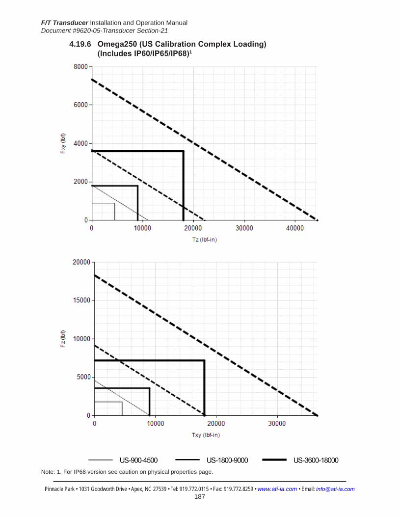
F/T Transducer Installation and Operation ManualDocument #9620-05-Transducer Section-21
Pinnacle Park • 1031 Goodworth Drive • Apex, NC 27539 • Tel: 919.772.0115 • Fax: 919.772.8259 • www.ati-ia.com • Email: [email protected] 187
4.19.6 Omega250(USCalibrationComplexLoading) (IncludesIP60/IP65/IP68)1
HelpOmega250 IP60/IP65/IP68
US-900-4500 US-1800-9000 US-3600-18000
Note: 1. For IP68 version see caution on physical properties page.
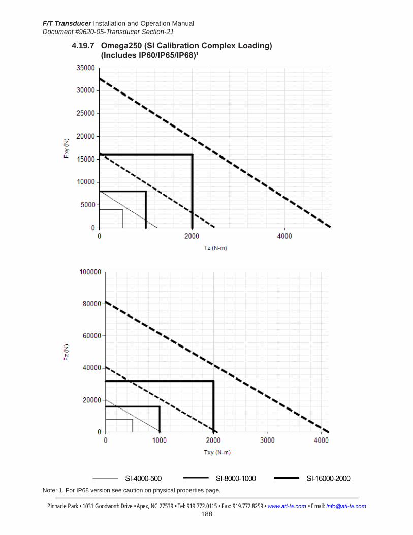
F/T Transducer Installation and Operation ManualDocument #9620-05-Transducer Section-21
Pinnacle Park • 1031 Goodworth Drive • Apex, NC 27539 • Tel: 919.772.0115 • Fax: 919.772.8259 • www.ati-ia.com • Email: [email protected] 188
4.19.7 Omega250(SICalibrationComplexLoading) (IncludesIP60/IP65/IP68)1
HelpOmega250 IP60/IP65/IP68
SI-4000-500 SI-8000-1000 SI-16000-2000
Note: 1. For IP68 version see caution on physical properties page.

F/T Transducer Installation and Operation ManualDocument #9620-05-Transducer Section-21
Pinnacle Park • 1031 Goodworth Drive • Apex, NC 27539 • Tel: 919.772.0115 • Fax: 919.772.8259 • www.ati-ia.com • Email: [email protected] 189
4.19.8 Omega250 IP60 Transducer Drawing
3rd
AN
GLE
PRO
JEC
TION
B.C
. 16
0
135°
171.
9
2X10
Slip
Fit
11C
usto
mer
Inte
rface
56.5
69±0
.025
80±0
.025
136.
569±
0.02
5
22.5
°
Cus
tom
er In
terfa
ceEq
ually
Spa
ced
14X
Tap
M12
X1.7
517
57.8
Mux
& D
AQSy
stem
136
.525
±0.0
25
273
.050
±0.0
25
2X
12.0
6012
.035
Slip
Fit
25.
4C
usto
mer
Inte
rface
45°
70.4
Net
Sys
tem
+X -X
-Y+Y
Con
nect
or F
or C
able
Varie
s D
epen
ding
on
Sens
or S
elec
ted
94.9
15.2
69.2
30.
5 M
ount
ing
Adap
ter p
late
Neo
pren
eR
ubbe
r D
ust J
acke
t
Sens
ing
Ref
eren
ceFr
ame
Orig
in
+Z
Tool
Adap
ter P
late
-Z
22.5
°
135°
B.C
. 20
0
57.1
7557
.125
17
Cus
tom
er In
terfa
ce
2X
12 S
lip F
it 10
Cus
tom
er In
terfa
ce
254
295
B.C
. 27
3.1
15°
2X 3
8.26
8±0.
025
92.3
88±0
.025
184.
776±
0.02
5
30°
11X
1
2.7
Thru
19.
3 1
2.4
For M
12 S
HC
SC
usto
mer
Inte
rface
Opt
iona
l Mou
ntin
g P
atte
rn
Sens
ing
Ref
eren
ceFr
ame
Orig
in+X -X
-Y+Y
14X
Tap
M12
x 1
.75
17Eq
ually
Spa
ced
Cus
tom
er In
terfa
ce
TOO
L SI
DE
SID
E VI
EW
ISO
MET
RIC
VIE
W
MO
UN
TIN
G S
IDE
Not
es: Mat
eria
l: St
ainl
ess
Stee
l and
Alu
min
um1.
Sens
ing
Ref
eren
ce F
ram
e O
rigin
at s
urfa
ce c
ente
r of T
ool A
dapt
er.
2.D
o no
t dis
asse
mbl
e tra
nsdu
cer.
Doi
ng s
o co
uld
dam
age
trans
duce
r 3.
and
will
void
war
rant
y.Fo
r bes
t acc
urac
y, tr
ansd
ucer
mus
t be
mou
nted
to a
sur
face
rigi
d4.
enou
gh to
sup
port
load
s w
ithou
t def
lect
ion.
Rev.
Des
crip
tion
Initi
ator
Dat
e
06EC
O11
873:
Add
ed 6
x ad
ditio
nal M
12 ta
pped
hol
es fo
r cu
stom
er in
terfa
ce to
TAP
and
MA
P. A
dded
2x
12m
m
SF d
owel
s to
the
MA
P fo
r cus
tom
er in
terfa
ce.
LTF
3/21
/201
4
B1:
2.5
11
REVI
SION
NO
TES:
UN
LESS
OTH
ERW
ISE
SPEC
IFIED
.
DO
NO
T SC
ALE
DRA
WIN
G.
ALL
DIM
ENSI
ON
S A
RE IN
M
ILLIM
ETER
S.
DRA
WN
BY:
CHE
CKE
D B
Y:
P.Sp
arro
w, 2
/16/
06
D.N
orto
n, 2
/17/
06
TITLE SC
ALE
SIZE
DRA
WIN
G N
UMBE
R
PRO
JEC
T #SH
EET
O
F 92
30-0
5-12
66-
06
PRO
PERT
Y O
F A
TI IN
DUS
TRIA
L A
UTO
MA
TION
, IN
C. N
OT T
O B
E RE
PRO
DUC
ED IN
AN
Y M
AN
NER
EXC
EPT O
N O
RDER
OR
WITH
PRI
OR
WRI
TTEN
AUT
HORI
ZATIO
N O
F A
TI.
1031
Goo
dwor
th Dr
ive, A
pex,
NC 27
539,
USA
Tel: +
1.919
.772.0
115
Em
ail: in
fo@ati
-ia.co
mFa
x: +1
.919.7
72.82
59
www
.ati-ia
.com
ISO
9001
Reg
ister
ed C
ompa
ny
IP60
Om
ega2
50 T
rans
duce
r
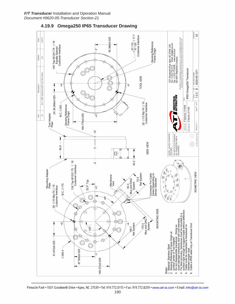
F/T Transducer Installation and Operation ManualDocument #9620-05-Transducer Section-21
Pinnacle Park • 1031 Goodworth Drive • Apex, NC 27539 • Tel: 919.772.0115 • Fax: 919.772.8259 • www.ati-ia.com • Email: [email protected] 190
4.19.9 Omega250 IP65 Transducer Drawing
3rd
AN
GLE
PRO
JEC
TION
57.1
7557
.125
17
.7C
usto
mer
Inte
rface
B.C
.20
0
2X
12 S
lip F
it 10
Cus
tom
er In
terfa
ce
Cus
tom
er In
terfa
ceEq
ually
Spa
ced
14X
Tap
M12
X1.7
5
182X
38.
268±
0.02
5
92.3
88±0
.025
184.
776±
0.02
5
TOO
L SI
DE
Sens
ing
Ref
eren
ceFr
ame
Orig
in
+X -X
-Y+Y
94.9
44.2
SID
E VI
EW
Mou
ntin
g Ad
apte
rPl
ate
Tool
Ada
pter
Plat
e
Sens
ing
Ref
eren
ceFr
ame
Orig
in
-Z+Z
175.
3M
ux a
nd D
AQ
Syst
em
260.
4B.
C.
175
135°
2X
10 S
lip F
it 10
Cus
tom
er In
terfa
ce 63.3
Mux
and
DAQ
Sy
stem
22.5
° Typ
.
Cus
tom
er In
terfa
ce13
X Ta
p M
12X1
.75
1
8
87.5
00±0
.025
149.
372±
0.02
5
61.8
72±0
.025
165.
7N
et S
yste
m70
.5N
et S
yste
m
45°
-Y
+X
+Y
-X
Mem
bran
eVe
nt
Con
nect
or F
or C
able
Varie
s D
epen
ding
on
Sens
or S
elec
ted
MO
UN
TIN
G S
IDE
ISO
MET
RIC
VIE
W
Not
es:
1. M
ater
ial:
Stai
nles
s St
eel
2. S
ensi
ng R
efer
ence
Fra
me
Orig
in a
t
sur
face
cen
ter o
f Too
l Ada
pter
.3.
Do
not d
isas
sem
ble
trans
duce
r. D
oing
so
c
ould
dam
age
trans
duce
r and
will
void
war
rant
y.4.
For
bes
t acc
urac
y, tr
ansd
ucer
mus
t be
mou
nted
to a
sur
face
rigi
d en
ough
to s
uppo
rt lo
ads
with
out d
efle
ctio
n.
5. C
able
mus
t be
conn
ecte
d to
tran
sduc
er to
mai
ntai
n pr
oper
sea
l.6.
Cab
le is
IP65
rate
d on
ly a
t Tra
nsdu
cer E
nd.
Rev.
Des
crip
tion
Initi
ator
Dat
e
03Ec
o 11
989;
Upd
ated
MA
P an
d TA
P pl
ates
.LJ
H6/
5/14
B1:
2.5
11
REVI
SION
NO
TES:
UN
LESS
OTH
ERW
ISE
SPEC
IFIED
.
DO
NO
T SC
ALE
DRA
WIN
G.
ALL
DIM
ENSI
ON
S A
RE IN
M
ILLIM
ETER
S.
DRA
WN
BY:
CHE
CKE
D B
Y:
P.Sp
arro
w, 2
/16/
06
D.N
orto
n 2/
17/0
6
TITLE SC
ALE
SIZE
DRA
WIN
G N
UMBE
R
PRO
JEC
T #SH
EET
O
F 92
30-0
5-12
71-
03
PRO
PERT
Y O
F A
TI IN
DUS
TRIA
L A
UTO
MA
TION
, IN
C. N
OT T
O B
E RE
PRO
DUC
ED IN
AN
Y M
AN
NER
EXC
EPT O
N O
RDER
OR
WITH
PRI
OR
WRI
TTEN
AUT
HORI
ZATIO
N O
F A
TI.
1031
Goo
dwor
th Dr
ive, A
pex,
NC 27
539,
USA
Tel: +
1.919
.772.0
115
Em
ail: in
fo@ati
-ia.co
mFa
x: +1
.919.7
72.82
59
www
.ati-ia
.com
ISO
9001
Reg
ister
ed C
ompa
ny
IP65
Om
ega2
50 T
rans
duce
r
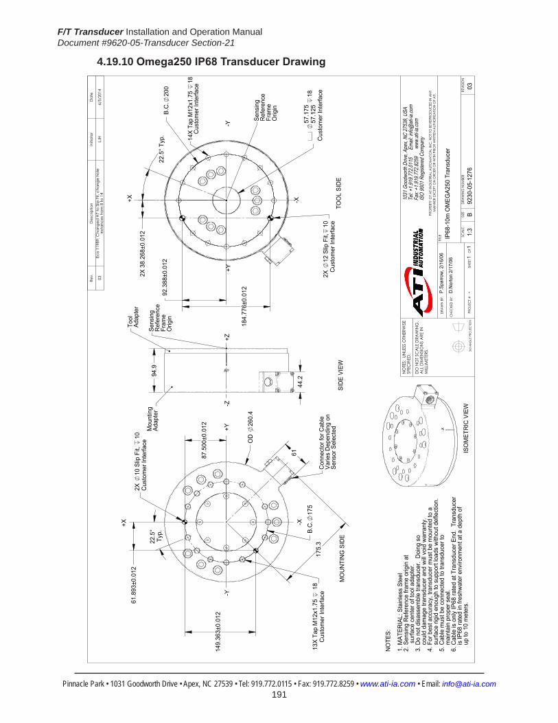
F/T Transducer Installation and Operation ManualDocument #9620-05-Transducer Section-21
Pinnacle Park • 1031 Goodworth Drive • Apex, NC 27539 • Tel: 919.772.0115 • Fax: 919.772.8259 • www.ati-ia.com • Email: [email protected] 191
4.19.10 Omega250IP68TransducerDrawing
3rd
AN
GLE
PRO
JEC
TION
B.C
.20
0
2X 3
8.26
8±0.
012
184.
776±
0.01
2
92.3
88±0
.012
2X
12 S
lip F
it,10
Cus
tom
er In
terfa
ce
57.1
7557
.125
18
Cus
tom
er In
terfa
ce
22.
5° T
yp.
TOO
L SI
DE
+Z
Sens
ing
Ref
eren
ceFr
ame
Orig
in
+X -X
-Y+Y
14X
Tap
M12
x1.7
5 18
Cus
tom
er In
terfa
ce
94.9
44.2
SID
E VI
EW
Mou
ntin
gAd
apte
r
Tool
Adap
ter
Sens
ing
Ref
eren
ceFr
ame
Orig
in
175.
3B.
C.
175
22.5
°Ty
p.
87.5
00±0
.012
149.
363±
0.01
2
61.8
93±0
.012
61
OD
26
0.4
Cus
tom
er In
terfa
ce13
X Ta
p M
12x1
.75
18
2X
10 S
lip F
it,
10C
usto
mer
Inte
rface
-Y
+X
+Y
-X
-Z
Con
nect
or fo
r Cab
leVa
ries
Dep
endi
ng o
nSe
nsor
Sel
ecte
d
NO
TES:
1. M
ATER
IAL:
Sta
inle
ss S
teel
2. S
ensi
ng R
efer
ence
fram
e or
igin
at
s
urfa
ce c
ente
r of t
ool a
dapt
er.
3. D
o no
t dis
asse
mbl
e tra
nsdu
cer.
Doi
ng s
o
cou
ld d
amag
e tra
nsdu
cer a
nd w
ill vo
id w
arra
nty.
4. F
or b
est a
ccur
acy,
tran
sduc
er m
ust b
e m
ount
ed to
a
s
urfa
ce ri
gid
enou
gh to
sup
port
load
s w
ithou
t def
lect
ion.
5.
Cab
le m
ust b
e co
nnec
ted
to tr
ansd
ucer
to
m
aint
ain
prop
er s
eal.
6. C
able
is o
nly
IP68
rate
d at
Tra
nsdu
cer E
nd.
Tran
sduc
er
is IP
68 ra
ted
in fr
eshw
ater
env
ironm
ent a
t a d
epth
of
u
p to
10
met
ers.
MO
UN
TIN
G S
IDE
ISO
MET
RIC
VIE
W
Rev.
Des
crip
tion
Initi
ator
Dat
e
03Ec
o 11
989;
Cha
nged
H7
to S
lip F
it, c
hang
e ho
le
inst
ance
s fro
m 8
to 1
4LJ
H6/
5/20
14
B1:
31
1RE
VISIO
N
NO
TES:
UN
LESS
OTH
ERW
ISE
SPEC
IFIED
.
DO
NO
T SC
ALE
DRA
WIN
G.
ALL
DIM
ENSI
ON
S A
RE IN
M
ILLIM
ETER
S.
DRA
WN
BY:
CHE
CKE
D B
Y:
P.Sp
arro
w, 2
/16/
06
D.N
orto
n 2/
17/0
6
TITLE SC
ALE
SIZE
DRA
WIN
G N
UMBE
R
PRO
JEC
T #SH
EET
O
F 92
30-0
5-12
76-
03
PRO
PERT
Y O
F A
TI IN
DUS
TRIA
L A
UTO
MA
TION
, IN
C. N
OT T
O B
E RE
PRO
DUC
ED IN
AN
Y M
AN
NER
EXC
EPT O
N O
RDER
OR
WITH
PRI
OR
WRI
TTEN
AUT
HORI
ZATIO
N O
F A
TI.
1031
Goo
dwor
th Dr
ive, A
pex,
NC 27
539,
USA
Tel: +
1.919
.772.0
115
Em
ail: in
fo@ati
-ia.co
mFa
x: +1
.919.7
72.82
59
www
.ati-ia
.com
ISO
9001
Reg
ister
ed C
ompa
ny
IP68
-10m
OM
EGA2
50 T
rans
duce
r

F/T Transducer Installation and Operation ManualDocument #9620-05-Transducer Section-21
Pinnacle Park • 1031 Goodworth Drive • Apex, NC 27539 • Tel: 919.772.0115 • Fax: 919.772.8259 • www.ati-ia.com • Email: [email protected] 192
4.20 Omega331Specifications(IncludesIP65)4.20.1 Omega331PhysicalProperties(IncludesIP65)
Table 4.114—Omega331PhysicalProperties(IncludesIP60/IP65)Single-Axis Overload (US)StandardUnits (SI)MetricUnitsFxy ±53000 lbf ±240000 NFz ±120000 lbf ±520000 NTxy ±280000 inf-lb ±32000 NmTz ±320000 inf-lb ±36000 NmStiffness(Calculated) X-axis&Y-axisforces(Kx,Ky) 6.9x10⁶ lb/in 1.2x10⁹ N/m Z-axisforce(Kz) 7.3x10⁶ lb/in 1.3x10⁹ N/m X-axis&Y-axistorque(Ktx,Kty) 8.1x10⁷ lbf-in/rad 9.2x10⁶ Nm/rad Z-axistorque(Ktz) 2.1x10⁸ lbf-in/rad 2.4x10⁷ Nm/rad Resonant Frequency Fx, Fy, Tz N/A N/AFz, Tx, Ty N/A N/APhysicalSpecifications Weight1 104 lb 47 kgDiameter1 13 in 330 mmHeight1 4.22 in 107 mmNote: 1.Specificationsincludestandardinterfaceplates.

F/T Transducer Installation and Operation ManualDocument #9620-05-Transducer Section-21
Pinnacle Park • 1031 Goodworth Drive • Apex, NC 27539 • Tel: 919.772.0115 • Fax: 919.772.8259 • www.ati-ia.com • Email: [email protected] 193
4.20.2 CalibrationSpecifications(excludesCTLcalibrations)
Table 4.115—Omega331Calibrations(excludesCTLcalibrations)1, 2
Sensor (US)Standard Calibration
Fx,Fy (lbf)
Fz (lbf)
Tx,Ty (lbf-in)
Tz (lbf-in)
Fx,Fy (lbf)
Fz (lbf)
Tx,Ty (lbf-in)
Tz (lbf-in)
Omega331 US-2250-13000 2250 5250 13000 13000 3/8 1 3 3/4 1 7/8Omega331 US-4500-26000 4500 10500 26000 26000 3/4 2 7 1/2 3 3/4Omega331 US-9000-52000 9000 21000 52000 52000 1 1/2 4 15 7 1/2
Sensor (SI)Metric Calibration
Fx,Fy (kN)
Fz (kN)
Tx,Ty (kNm)
Tz (kNm)
Fx,Fy (kN)
Fz (kN)
Tx,Ty (kNm)
Tz (kNm)
Omega331 SI-10000-1500 10 22 1.5 1.5 1/640 1/240 3/8000 3/16000Omega331 SI-20000-3000 20 44 3 3 1/320 1/120 3/4000 3/8000Omega331 SI-40000-6000 40 88 6 6 1/160 1/60 3/2000 3/4000
Sensing Ranges Resolution(DAQ,NetF/T)3
Notes: 1. These system resolutions quoted are the effective resolution after dropping four counts of noise. Theeffectiveresolutioncanbeimprovedwithfiltering. 2. Applied loads must be within range in each of the six axes for the F/T sensor to measure correctly. 3. DAQ resolutions are typical for a 16-bit data acquisition system.
4.20.3 CTLCalibrationSpecifications
Table 4.116— Omega331 CTL Calibrations1, 2
Sensor (US)Standard Calibration
Fx,Fy (lbf)
Fz (lbf)
Tx,Ty (lbf-in)
Tz (lbf-in)
Fx,Fy (lbf)
Fz (lbf)
Tx,Ty (lbf-in)
Tz (lbf-in)
Omega331 US-2250-13000 2250 5250 13000 13000 3/4 2 7 1/2 3 3/4Omega331 US-4500-26000 4500 10500 26000 26000 1 1/2 4 15 7 1/2Omega331 US-9000-52000 9000 21000 52000 52000 3 8 30 15
Sensor (SI)Metric Calibration
Fx,Fy (kN)
Fz (kN)
Tx,Ty (kNm)
Tz (kNm)
Fx,Fy (kN)
Fz (kN)
Tx,Ty (kNm)
Tz (kNm)
Omega331 SI-10000-1500 10 22 1.5 1.5 1/320 1/120 3/4000 3/8000Omega331 SI-20000-3000 20 44 3 3 1/160 1/60 3/2000 3/4000Omega331 SI-40000-6000 40 88 6 6 1/80 1/30 3/1000 3/2000
Sensing Ranges Resolution(Controller)Notes: 1. CTL resolutions are typical. System resolutions quoted are the effective resolution after dropping eight countsofnoise.Theeffectiveresolutioncanbeimprovedwithfiltering. 2. Applied loads must be within range in each of the six axes for the F/T sensor to measure correctly.

F/T Transducer Installation and Operation ManualDocument #9620-05-Transducer Section-21
Pinnacle Park • 1031 Goodworth Drive • Apex, NC 27539 • Tel: 919.772.0115 • Fax: 919.772.8259 • www.ati-ia.com • Email: [email protected] 194
4.20.4 Analog Output
Table 4.117— Omega331 Analog Output
Sensor (US)Standard Calibration
Fx,Fy (lbf)
Fz (lbf)
Tx,Ty,Tz (lbf-in)
Fx,Fy (lbf/V)
Fz (lbf/V)
Tx,Ty,Tz (lbf-in/V)
Omega331 US-2250-13000 ±2250 ±5250 ±13000 225 525 1300Omega331 US-4500-26000 ±4500 ±10500 ±26000 450 1050 2600Omega331 US-9000-52000 ±9000 ±21000 ±52000 900 2100 5200
Sensor (SI)Metric Calibration
Fx,Fy (kN)
Fz (kN)
Tx,Ty,Tz (kNm)
Fx,Fy (kN/V)
Fz (kN/V)
Tx,Ty,Tz (kNm/V)
Omega331 SI-10000-1500 ±10 ±22 ±1.5 1 2.2 0.15Omega331 SI-20000-3000 ±20 ±44 ±3 2 4.4 0.3Omega331 SI-40000-6000 ±40 ±88 ±6 4 8.8 0.6
Analog Output Range Analog±10VSensitivity1
Notes: 1. ±5V Sensitivity values are double the listed ±10V Sensitivity values.
4.20.5 CountsValueTable4.118—CountsValue
Sensor Calibration Fx,Fy,Fz (/lbf)
Tx,Ty,Tz (/lbf-in)
Fx,Fy,Fz (/kN)
Tx,Ty,Tz (/kNm)
Omega331 US-2250–13000/SI-10000–1500 32 6.4 7680 64000Omega331 US-4500–26000/SI-20000–3000 16 3.2 3840 32000Omega331 US-9000–52000/SI-40000–6000 8 1.6 1920 16000Omega331 Tool Transform Factor 0.05 in/lbf 1.2 mm/N
CountsValue–Standard(US) CountsValue–Metric(SI)

F/T Transducer Installation and Operation ManualDocument #9620-05-Transducer Section-21
Pinnacle Park • 1031 Goodworth Drive • Apex, NC 27539 • Tel: 919.772.0115 • Fax: 919.772.8259 • www.ati-ia.com • Email: [email protected] 195
4.20.6 Omega331(USCalibrationComplexLoading)(IncludesIP65)
HelpOmega331
US-2250-13000 US-4500-26000 US-9000-52000

F/T Transducer Installation and Operation ManualDocument #9620-05-Transducer Section-21
Pinnacle Park • 1031 Goodworth Drive • Apex, NC 27539 • Tel: 919.772.0115 • Fax: 919.772.8259 • www.ati-ia.com • Email: [email protected] 196
4.20.7 Omega331(SICalibrationComplexLoading)(IncludesIP65)
HelpOmega331
SI-10000-1500 SI-20000-3000 SI-40000-6000

F/T Transducer Installation and Operation ManualDocument #9620-05-Transducer Section-21
Pinnacle Park • 1031 Goodworth Drive • Apex, NC 27539 • Tel: 919.772.0115 • Fax: 919.772.8259 • www.ati-ia.com • Email: [email protected] 197
4.20.8 Omega331 Transducer Drawing
3rd
AN
GLE
PRO
JEC
TION
226
.824
±0.0
25
151
.559
±0.0
25
28.
803±
0.02
5
177
.5
2X
12 S
lip F
it 12
Cus
tom
er In
terfa
ce
B.C
. 29
5.3
16X
M12
X1.7
5 Th
ruEq
ually
Spa
ced
Cus
tom
er In
terfa
ce
144
.801
±0.0
25
120.
900
120.
650
3C
usto
mer
Inte
rface
30°
MO
UN
TIN
G S
IDE
ISO
MET
RIC
VIE
W N
otes
: Mat
eria
l: H
arde
ned
Stai
nles
s St
eel a
nd A
lum
inum
1.
DO
NO
T EX
CEE
D IN
TER
FAC
E D
EPTH
, MA
Y C
AU
SE D
AM
AG
E.2.
Do
not d
isas
sem
ble
trans
duce
r. D
oing
so
coul
d da
mag
e tra
nsdu
cer a
nd w
ill vo
id th
e w
arra
nty
3. F
or b
est a
ccur
acy
trans
duce
r mus
t be
mou
nted
to a
sur
face
rigi
d en
ough
4.
to
sup
port
load
s w
ithou
t def
lect
ion.
+X -X
+Y-Y
Con
nect
or fo
r Cab
leVa
ries
Dep
endi
ng o
nSe
nsor
Sel
ecte
d
30.
7 2
9.8
107
33
0
254
18
Sens
ing
Ref
eren
ceFr
ame
Orig
in
Mou
ntin
gAd
apte
rPl
ate
Tool
Adap
ter
Plat
e
+Z-Z
SID
E VI
EW
2X
82.0
23±0
.025
B.C
.29
5.3
122
.756
±0.0
25
245
.512
±0.0
25
120.
900
120.
650
6C
usto
mer
Inte
rface
16X
M12
X1.7
5 Th
ruEq
ually
Spa
ced
Cus
tom
er In
terfa
ce
2X
12 S
lip F
it 12
Cus
tom
er In
terfa
ce
Sens
ing
Ref
eren
ceFr
ame
Orig
in
TOO
L SI
DE
-Y+Y
-X+X
Con
nect
or fo
r Cab
le
Rev.
Des
crip
tion
Initi
ator
Dat
e
04Ec
o 11
586;
Mod
ified
MA
P an
d TA
P to
elim
inat
e le
gacy
fe
atur
es. A
dded
dim
ensio
ns fo
r NET
ver
sion.
A
P11
/6/2
013
B1:
31
1RE
VISIO
N
NO
TES:
UN
LESS
OTH
ERW
ISE
SPEC
IFIED
.
DO
NO
T SC
ALE
DRA
WIN
G.
ALL
DIM
ENSI
ON
S A
RE IN
M
ILLIM
ETER
S.
DRA
WN
BY:
CHE
CKE
D B
Y:
D N
orto
n 10
/03/
03
P Fu
sco
7/17
/06
TITLE SC
ALE
SIZE
DRA
WIN
G N
UMBE
R
PRO
JEC
T #SH
EET
O
F 92
30-0
5-11
58-
04
PRO
PERT
Y O
F A
TI IN
DUS
TRIA
L A
UTO
MA
TION
, IN
C. N
OT T
O B
E RE
PRO
DUC
ED IN
AN
Y M
AN
NER
EXC
EPT O
N O
RDER
OR
WITH
PRI
OR
WRI
TTEN
AUT
HORI
ZATIO
N O
F A
TI.
1031
Goo
dwor
th Dr
ive, A
pex,
NC 27
539,
USA
Tel: +
1.919
.772.0
115
Em
ail: in
fo@ati
-ia.co
mFa
x: +1
.919.7
72.82
59
www
.ati-ia
.com
ISO
9001
Reg
ister
ed C
ompa
ny
Om
ega3
31 T
rand
ucer

F/T Transducer Installation and Operation ManualDocument #9620-05-Transducer Section-21
Pinnacle Park • 1031 Goodworth Drive • Apex, NC 27539 • Tel: 919.772.0115 • Fax: 919.772.8259 • www.ati-ia.com • Email: [email protected] 198
4.20.9 Omega331 IP65 Transducer Drawing
3rd
AN
GLE
PRO
JEC
TION
226.
824±
0.02
5
144.
801±
0.02
5
151.
559±
0.02
5
28.8
03±0
.025
211
30°
61.1
DAQ
Sys
tem
B.C
. 29
5.3
(2)
12 S
lip F
it 12
Cus
tom
er In
terfa
ce
25.4
Cus
tom
er in
terfa
ceEq
ually
Spa
ced
(16)
M
12X1
.75
Thru
71.4
Net
Sys
tem
MO
UN
TIN
G S
IDE
-Y+Y
+X -X
330
254
107
30.7
29.8
10.4
55.6
Tool
Ad
apte
rPl
ate
Mou
ntin
g Ad
apte
rPl
ate
Sens
ing
Ref
eren
ce
Fram
e O
rigin
SID
E VI
EW
-Z+Z
(2) 8
2.02
3±0.
025
122.
756±
0.02
5
245.
512±
0.02
5
Cus
tom
er in
terfa
ceEq
ually
Spa
ced
(16)
M
12X1
.75
Thru
(2)
12 S
lip F
it 12
Cus
tom
er In
terfa
ceB.
C.
295.
3Sens
ing
Ref
eren
ce
Fram
e O
rigin
TOO
L SI
DE
-Y+Y
+X
-X
Not
es: Mou
ntin
g an
d To
ol A
dapt
er m
ade
of s
tain
less
ste
el.
Tran
sduc
er
1.bo
dy m
ade
of h
arde
ned
stai
nles
s st
eel.
Sens
ing
refe
renc
e fra
me
orig
in a
t sur
face
cen
ter o
f too
l ada
pter
.2.
War
ning
: Do
not l
oose
n or
rem
ove
inte
rfac
e pl
ates
due
to3.
pote
ntia
l dam
age.
For b
est a
ccur
acy,
tran
sduc
er m
ust b
e m
ount
ed to
sur
face
s rig
id
4.en
ough
to s
uppo
rt lo
ads
with
out d
efle
ctio
n.
Rev.
Des
crip
tion
Initi
ator
Dat
e
02A
dded
Net
Ver
sion
RKC
3/8/
2011
B1:
31
1RE
VISIO
N
NO
TES:
UN
LESS
OTH
ERW
ISE
SPEC
IFIED
.
DO
NO
T SC
ALE
DRA
WIN
G.
ALL
DIM
ENSI
ON
S A
RE IN
M
ILLIM
ETER
S.
DRA
WN
BY:
CHE
CKE
D B
Y:
R. C
ham
bers
9/1
1/09
P. F
usco
9/1
1/09
TITLE SC
ALE
SIZE
DRA
WIN
G N
UMBE
R
PRO
JEC
T #SH
EET
O
F 92
30-0
5-13
6009
0904
-102
PRO
PERT
Y O
F A
TI IN
DUS
TRIA
L A
UTO
MA
TION
, IN
C. N
OT T
O B
E RE
PRO
DUC
ED IN
AN
Y M
AN
NER
EXC
EPT O
N O
RDER
OR
WITH
PRI
OR
WRI
TTEN
AUT
HORI
ZATIO
N O
F A
TI.
1031
Goo
dwor
th Dr
ive, A
pex,
NC 27
539,
USA
Tel: +
1.919
.772.0
115
Em
ail: in
fo@ati
-ia.co
mFa
x: +1
.919.7
72.82
59
www
.ati-ia
.com
ISO
9001
Reg
ister
ed C
ompa
ny
IP65
Om
ega3
31 T
rans
duce
r
F/T Transducer Installation and Operation ManualDocument #9620-05-Transducer Section-21
Pinnacle Park • 1031 Goodworth Drive • Apex, NC 27539 • Tel: 919.772.0115 • Fax: 919.772.8259 • www.ati-ia.com • Email: [email protected] 199
5. Advanced Topics5.1 Reducing Noise
5.1.1 MechanicalVibrationIn many cases, perceived noise is actually a real fluctuation of force and/or torque, caused by vibrations in the tooling or the robot arm. Many F/T systems offer filtering or averaging that can smooth out noise. If this is not sufficient, you may want to add a digital filter to the application software.
5.1.2 Electrical InterferenceCheck the F/T’s ground connections if you observe interference by motors or other noise-generating equipment.Consider using averaging or filtering if sufficient grounding is not possible or does not reduce the noise.
5.2 DetectingFailures(Diagnostics)5.2.1 Detecting Sensitivity Changes
Sensitivity checking of the transducer can also be used to measure the transducer system’s health. This is done by applying known loads to the transducer and verifying the system output matches the known loads. For example, a transducer mounted to a robot arm may have an end-effector attached to it:If the end-effector has moving parts, they must be moved in a known position. Place the robot arm in an orientation that allows the gravity load from the end-effector to exert load on many transducer output axes.Record the output readings.Position the robot arm to apply another load, this time causing the outputs to move far from the earlier readings.Record the second set of output readings.Find the differences from the first and second set of readings and use it as your sensitivity value.Even if the values vary somewhat from sample set to sample set, they can be used to detect gross errors. Either the resolved outputs or the raw transducer voltages may be used (the same must be used for all steps of this process).
CAUTION: When any strain gage is saturated or otherwise inoperable, all transducer F/T readings are invalid. It is vitally important to monitor for these conditions.
5.3 Scheduled Maintenance5.3.1 Periodic Inspection
For most applications, there are no parts that need to be replaced during normal operation. With industrial-type applications that continuously or frequently move the system’s cabling, you should periodically check the cable jacket for signs of wear. These applications should implement the procedures discussed in Section 5.2—Detecting Failures (Diagnostics) to detect any failures.Transducers that are not IP60, IP65, or IP68 rated must be kept free of excessive dust, debris, or moisture. IP60-rated transducers must be kept free of excessive moisture. Debris and dust should be kept from accumulating on or in a transducer.

F/T Transducer Installation and Operation ManualDocument #9620-05-Transducer Section-21
Pinnacle Park • 1031 Goodworth Drive • Apex, NC 27539 • Tel: 919.772.0115 • Fax: 919.772.8259 • www.ati-ia.com • Email: [email protected] 200
5.3.2 Periodic CalibrationPeriodic calibration of the transducer and its electronics is required to maintain traceability to national standards. Follow any applicable ISO-9000-type standards for calibration. ATI Industrial Automation recommends annual recalibrations, especially for applications that frequently cycle the loads applied to the transducer.
5.4 Transducer Cabling5.4.1 Calibrations
In many cases the transducer cable comprises part of the calibrated transducer. In these cases, changing the length or type of the cable can affect the calibration. Check with ATI Industrial Automation when making cabling changes to ensure your system’s calibration will not be affected.
5.4.2 Cabling and ConnectorsThe transducer cables and connectors are not designed to be user serviceable. The high flex life stranding used in the cable is difficult to work with and will fail prematurely if improperly assembled.However, there are special cases when customers find it necessary to temporarily remove the connector on a cable that is permanently attached to a transducer (such as found on the Nano and Mini series transducers). When reattaching the wires to the connector, it is vital that each conductor is encased in heat shrink tubing at the connection to prevent premature fatiguing of the mechanical connection. Also, any components contained in the connector must be reconnected exactly as found – failing to do so will impact system performance and accuracy.Damage to the outer jacketing of the transducer cable could enable moisture or water to enter an otherwise sealed transducer. Ensure the cable jacketing is in good condition to prevent transducer damage.
5.5 ResolutionATI’s transducers have a three sensing beam configuration where the three beams are equally spaced around a central hub and attached to the outside wall of the transducer. This design transfers applied loads to multiple sensing beams and allows the transducer to increase its sensing range in a given axis if a counterpart axis has reduced.The resolution of each transducer axis depends on how the applied load is spread among the sensing beams. The best resolution occurs in the scenario when the quantization of the gages is evenly distributed as load is applied. In the worst case scenario, the discrete value of all involved gages increases at the same time. The typical scenario will be somewhere between these two.F/T resolutions are specified as typical resolution, defined as the average of the worst and best case scenarios. Because both multi-gage effects can be modeled as a normal distribution, this value represents the most commonly perceived, average resolution. Although this misrepresents the actual performance of the transducers, it results in a close (and always conservative) estimate.

F/T Transducer Installation and Operation ManualDocument #9620-05-Transducer Section-21
Pinnacle Park • 1031 Goodworth Drive • Apex, NC 27539 • Tel: 919.772.0115 • Fax: 919.772.8259 • www.ati-ia.com • Email: [email protected] 201
6. Terms and Conditions of SaleThe following Terms and Conditions are a supplement to and include a portion of ATI’s Standard Terms and Conditions, which are on file at ATI and available upon request.
ATI warrants to Purchaser that force torque sensor products purchased hereunder will be free from defects in material and workmanship under normal use for a period of one year from the date of shipment. This warranty does not cover components subject to wear and tear under normal usage or those requiring periodic replacement. ATI will have no liability under this warranty unless: (a) ATI is given written notice of the claimed defect and a description thereof within thirty (30) days after Purchaser discovers the defect and in any event not later than the last day of the warranty period; and (b) the defective item is received by ATI not later ten (10) days after the last day of the warranty period. ATI’s entire liability and Purchaser’s sole remedy under this warranty is limited to repair or replacement, at ATI’s election, of the defective part or item or, at ATI’s election, refund of the price paid for the item. The foregoing warranty does not apply to any defect or failure resulting from improper installation, operation, maintenance or repair by anyone other than ATI.
ATI will in no event be liable for incidental, consequential or special damages of any kind, even if ATI has been advised of the possibility of such damages. ATI’s aggregate liability will in no event exceed the amount paid by purchaser for the item which is the subject of claim or dispute. ATI will have no liability of any kind for failure of any equipment or other items not supplied by ATI.
No action against ATI, regardless of form, arising out of or in any way connected with products or services supplied hereunder may be brought more than one year after the cause of action accrued.
No representation or agreement varying or extending the warranty and limitation of remedy provisions contained herein is authorized by ATI, and may not be relied upon as having been authorized by ATI, unless in writing and signed by an executive officer of ATI.
Unless otherwise agreed in writing by ATI, all designs, drawings, data, inventions, software and other technology made or developed by ATI in the course of providing products and services hereunder, and all rights therein under any patent, copyright or other law protecting intellectual property, shall be and remain ATI’s property. The sale of products or services hereunder does not convey any express or implied license under any patent, copyright or other intellectual property right owned or controlled by ATI, whether relating to the products sold or any other matter, except for the license expressly granted below.
In the course of supplying products and services hereunder, ATI may provide or disclose to Purchaser confidential and proprietary information of ATI relating to the design, operation or other aspects of ATI’s products. As between ATI and Purchaser, ownership of such information, including without limitation any computer software provided to Purchaser by ATI, shall remain in ATI and such information is licensed to Purchaser only for Purchaser’s use in operating the products supplied by ATI hereunder in Purchaser’s internal business operations.
Without ATI’s prior written permission, Purchaser will not use such information for any other purpose or provide or otherwise make such information available to any third party. Purchaser agrees to take all reasonable precautions to prevent any unauthorized use or disclosure of such information.
Purchaser will not be liable hereunder with respect to disclosure or use of information which: (a) is in the public domain when received from ATI; (b) is thereafter published or otherwise enters the public domain through no fault of Purchaser; (c) is in Purchaser’s possession prior to receipt from ATI; (d) is lawfully obtained by Purchaser from a third party entitled to disclose it; or (f) is required to be disclosed by judicial order or other governmental authority, provided that, with respect to such required disclosures, Purchaser gives ATI prior notice thereof and uses all legally available means to maintain the confidentiality of such information.