sizing conduit and tubing by bill bamford.xls
TRANSCRIPT

7/27/2019 Sizing Conduit and Tubing by Bill Bamford.xls
http://slidepdf.com/reader/full/sizing-conduit-and-tubing-by-bill-bamfordxls 1/8
INSTRUCTIONS:
This is a caution or warning window
which pops us whenever a condition
may exist which could jeopardize the
calculations or raceway size.
Chapter 9 Tab
The total number of all wire and/or cable types or sizes
The total number of all wires and/or cables
This cell contain the NEC fill % allowance
Step 1 - Select the type raceway for the job using the pull
down box.Step 2 - Select whether or not the raceway will be a nipple
using the pulldown box. (one of the pull down boxes is
shown here.)
This cell displays the minimum size available raceway
which the NEC will allow for the selected conductors
and/or cables. Whenever it is not selected (indicated by
wihite arrow), it is still somewhat visible.
- Enter the quantity of the first group of conductors
and/orcables on Group Row 1.
Enter your data into the sizing Conduit worksheet in the
following order:
If you have more than one size conductor or cable, enter
their data on the next Group row, repeating step three for
up to ten groups of conductors/cables in the raceway.
These two
visible whe
conductors
of the sam
size.
This sprea
developed
Services ,
provided at
get what yo
The NEC s
any and allfound herei
Sizing Conduit / Tubing - Instr uct io ns and Information
If any erro
however, p
the f
so that t
corre
redist
- If you are installing cables in raceways, enter the
diameter of the cable using either decimals or fractions
on Group Row 1.
Step 3 - Enter the conductors and/or cables for Group
Rows 1 - 10 as follows:.
This white arror points to the selected
raceway size that is being used for
raceway calculations by the bottom
section of this screen
- If you are installing conductors in raceways, select the
type of conductor and the wire size using the pull down
boxes on Group Row 1.
Bill_B
Yah
The total fill % as calculated by note 7
of chapter 9.
INFORMATION: The total area of all conductors minus 20% of
one wire as calculated by note 7 of Chapter 9.
This windo
visible whe
possibility o
per Table 1ational Not
conductors
in the cond
are of the s
size, the ja
calculated
Chapter 9
All the codes and tables used for sizing conduit and tubing
(round raceways) are taken from chapter 9. There are 5
tables with two informational notes on Table 1, and nine
notes to the chapter 9 tables which provide therequirements for sizing round raceways:
Step 5 - If you selected to overide the NEC minimum size
raceway, you must select a raceway size using the pulldown box.
This Instruction WorksheetSizing Conduit/Tubing Worksheet
The total sq" of all
conductors and cables.
WireLab Brochure Worksheet
Note 1 allows the use of NEC Annex C (an
informational note) for making raceway
calculations when all conductors are the samesize in the raceway.
Note 2 allows larger fill for conduit/tubing that will
only be used to protect exposed wiring from
physical damage. It can be filled to 100%.
Note: If either a 3/8" FMC, or LFMC is indicated, check
NEC Table 348.22 before installing the conduit to verify
the installation. The NEC does not give tubing sizes for
FNT other than for 3/8" in Table 348.22 and therefore is
not supported with this spreadsheet.
Step 4 - If you want to override the NEC minimum size
raceway, select Yes in the pull down box.
This cell contains the actual fill %. Occassionally, this %
will exceed the allowable fill allowance because the NEC
does not count 20% of one wire or cable if all wires and
cables in the raceway are the same size per note 7.
Note 3 states that equipment grounding or
bonding conductors must also be included when
calculating the total conductor area.
The total available sq" inside
the selected raceway.
Table 8 provides the dia
the square inches for bar
Note 9 states that
multiconductor cables
shall be treated as a
single conductor for
calculating the fill% by
measuring the diameter
of cables at their widest
point.
Note 6 states that if a combination of conductors of
different sizes or types are used, then Tables 5 and 5A
and Table 4 provide the sq" required for calculations.
Note 7 states that if all conductors in the raceway are the
same size, then the total area of all conductors can be
reduced by 20% of one conductor. Note 7 is used by
Annex C when it ocassionaly allows an extra wire in the
raceway such as: 22 each 14AWG THHN wires in 3/4"
instead of 1" EMT. This spreadsheet accomplishes thisby adding the square inches of all of the wires or cables
and then subtracting 20% of one of the wires or cables to
Note 4 states that nipples 24" in length or
shorter can be filled to 60%. When sizing the
wires inside of nipples, the adjustment factors of Table 310.15(B)(3)(a) need not be applied. This
spreadsheet only allows 31% fill for 2 conductors
Annex C - If all of the conductors are the same size,
Annex C has raceway tables with calculations based on
Chapter 9 reqiirements. Just find the raceway type andlook up the conductor size to determine the raceway size.
The Annex C tables are not used for cables mixed
Table 1 gives the percent
for all types of raceways.
Informational Note:1
the percent fill allowe
will not necessarily be
all conditions.
Informational Note:2
jamming can occur w
three conductors/cabl
raceway if the jammin
between 2.8 and 3.2.
Table 4 provides the diafill area of most types of c
tubing allowed by the NE
Table 5 provides the dia
the square inches for mo
conductors and fixture wi
by the NEC.
Table 5A provides the di
the square inches for all c
aluminum conductors all
NEC, including bare com
aluminum conductors.
Note 8 states that bare
conductors which are
allowed in conduit/tubingmust be sized by Table 8.
This cell displays the inside
diameter of the selected raceway.
When only 3 wires or cables are
entered, this cell displays the
jamming ratio for the selected
raceway per Informational Note 2
This cell displays the inside
diameter of the selected conductor.
Chapter 9 Notes to Tables
Note 5 states that conductors not included in Chapter
nine, such as multiconductor cables, must be manually
calculated using their actual dimensions. Thisspreadsheet allows the input of cables by inputing their
widest diameter using either decimal or fractions.

7/27/2019 Sizing Conduit and Tubing by Bill Bamford.xls
http://slidepdf.com/reader/full/sizing-conduit-and-tubing-by-bill-bamfordxls 2/8
aluminum conductors.
give the square" to be used.
in nipples.
conductor sizes, bare wires, or for nipples.

7/27/2019 Sizing Conduit and Tubing by Bill Bamford.xls
http://slidepdf.com/reader/full/sizing-conduit-and-tubing-by-bill-bamfordxls 3/8
les
cells are only
n all
or cables are
type and
sheet was
by WireLab
nd is
no cost (you
u pay for).
uperceeds
informationn.
rs are found,
lease contact
llowing
hey can be
ted and
ributed:
mford @
o.com
is only
n there is a
f jamming
Inform-2. If only 3
or cables are
uit and they
ame type and
ming ratio is
eters and
fill allowance
States that
by table one
adequate for
States that
en pulling
es into a
g ratio is
eters and %onduit and
.
eters and
t insulated
es allowed
meters and
ompact
wed by the
pact

7/27/2019 Sizing Conduit and Tubing by Bill Bamford.xls
http://slidepdf.com/reader/full/sizing-conduit-and-tubing-by-bill-bamfordxls 4/8

7/27/2019 Sizing Conduit and Tubing by Bill Bamford.xls
http://slidepdf.com/reader/full/sizing-conduit-and-tubing-by-bill-bamfordxls 5/8
Complete in order the following 4-5 steps:
1. Select type of Conduit or Tubing: NEC's Minimum Size Raceway = 1"
. se t s pu own ox to n cate w et er t s s or a n pp e: No . se t s pu own ox to overr e t e raceway s ze : No
. nter a con uctors an or ca es e ow us ng pu own oxes: . se t s pu own ox to se ect an overr e raceway s ze:
Group Qty Dia. Area Qty Area
1 3 0.3840 0.1158 0.3474 sq" 3 0.0000 0.0000 sq"2 0.0000 0.0000 sq" 0.0000 0.0000 sq"
3 0.0000 0.0000 sq" 0.0000 0.0000 sq"
4 0.0000 0.0000 sq" 0.0000 0.0000 sq"
5 0.0000 0.0000 sq" 0.0000 0.0000 sq"
6 0.0000 0.0000 sq" 0.0000 0.0000 sq"
7 0.0000 0.0000 sq" 0.0000 0.0000 sq"
8 0.0000 0.0000 sq" 0.0000 0.0000 sq"
9 0.0000 0.0000 sq" 0.0000 0.0000 sq"
10 0.0000 0.0000 sq" 0.0000 0.0000 sq"
Cable diameters can be decimal or fraction.
1 sq" 2.73
3 Total inside area of raceway = sq" 1.049 "
40% 0.384 "
Actual raceway fill % = sq"
*Ch9 Table 1 Note 7 is tabulated into these figures, which should give the same results as Annex C
Warning: Do not use cut and paste on the yellow cells. It messes up the pull down lists. If you do, you may have to reload the entire program.
Total Area Cable Dia. Total Area
OK - Jamming Ratio =
2
While every effort has been
made to achieve a work of
high quality, the author does
not guarantee the accuracyof this spreadsheet.
Please report any errors found,
so that they can be corrected
and redistributed.
Send to:
This Excel Spreadsheet was
developed by WireLab Services which specializes in
resources for electricians.
It is provided for use at no cost
and may be freely copied and
shared as long as it is not
modified in any way.
Mike Holt provides two other
WireLab Services productson his excellent Website
"MikeHolt.com". One is
a handout on conduit bending
and the other is a spreadsheet
on voltage drop calculations.
CAUTION: CHECK JAMMING RATION BELOW!
Chapter 9, Table 1, Informational Note 2 of the NEC warns that "JAMMING"can occur whenever 3 equal sized conductors or cables are run in conduit
or tubing and the ratio between the inside diameter of the conduit or tubing
divided by one of the wire's or cables diameter is between 2.8 and 3.2.
EMT (Thinwall)
THHN, THWN, THWN-2
100% - (20% of 1 wire) =Selected Fill Percentage =
Only Enter Data into Yellow Cells Calculated information
Last updated - April 4, 2012
Bad Results
Per 2011 NEC
Sizing Conduit / Tubing
Number of wire/cable sizes =
Number of conductors/cables =
Single conductors Wire Size
<
The white arrow below indicates the selected raceway size:
Good Results
Inside Diameter of raceway =
100% - (20% of 1 wire) =40.21% 0.3242
0.8640
37.53% Diameter of one conductor =
100% of all wires/cables = 0.3474
7/27/2019 Sizing Conduit and Tubing by Bill Bamford.xls
http://slidepdf.com/reader/full/sizing-conduit-and-tubing-by-bill-bamfordxls 6/8
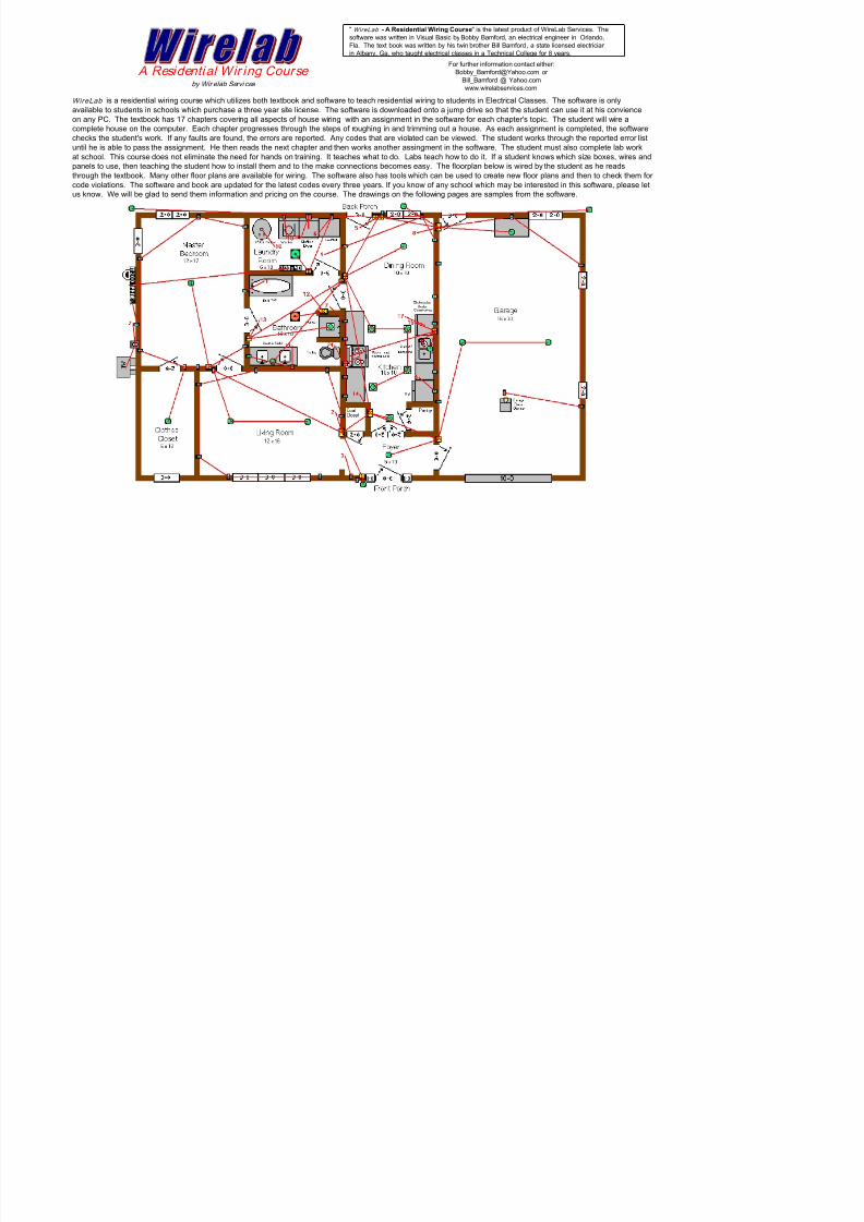
" WireLab - A Residential Wiring Course" is the latest product of WireLab Services. The
software was written in Visual Basic by Bobby Bamford, an electrical engineer in Orlando,
Fla. The text book was written by his twin brother Bill Bamford, a state licensed electrician
in Albany, Ga, who taught electrical classes in a Technical College for 8 years.
WireLab is a residential wiring course which utilizes both textbook and software to teach residential wiring to students in Electrical Classes. The software is onlyavailable to students in schools which purchase a three year site license. The software is downloaded onto a jump drive so that the student can use it at his convience
on any PC. The textbook has 17 chapters covering all aspects of house wiring with an assignment in the software for each chapter's topic. The student will wire a
complete house on the computer. Each chapter progresses through the steps of roughing in and trimming out a house. As each assignment is completed, the software
checks the student's work. If any faults are found, the errors are reported. Any codes that are violated can be viewed. The student works through the reported error list
until he is able to pass the assignment. He then reads the next chapter and then works another assingment in the software. The student must also complete lab work
at school. This course does not eliminate the need for hands on training. It teaches what to do. Labs teach how to do it. If a student knows which size boxes, wires and
panels to use, then teaching the student how to install them and to the make connections becomes easy. The floorplan below is wired by the student as he reads
through the textbook. Many other floor plans are available for wiring. The software also has tools which can be used to create new floor plans and then to check them for
code violations. The software and book are updated for the latest codes every three years. If you know of any school which may be interested in this software, please let
us know. We will be glad to send them information and pricing on the course. The drawings on the following pages are samples from the software.
A Residential Wir ing Course by Wir elab Servi ces
For further information contact either:
Bill_Bamford @ Yahoo.com
www.wirelabservices.com

7/27/2019 Sizing Conduit and Tubing by Bill Bamford.xls
http://slidepdf.com/reader/full/sizing-conduit-and-tubing-by-bill-bamfordxls 7/8
Panels must be wired, with proper breaker selection Sample trim-out inspection All receptacles, switches, lights, and appliances must be wired
Each cable wire in the panel must be pulled to the appropriate
ground bar, neutral bar or breaker. The main bonding jumper
must also be installed, if required. Once the panel is wired, the
power can be turned on. Then each main breaker, branch circuitbreaker or switch can be toggled to turn on and off any ceiling
fans, lights, receptacles, appliances, etc.
7/27/2019 Sizing Conduit and Tubing by Bill Bamford.xls
http://slidepdf.com/reader/full/sizing-conduit-and-tubing-by-bill-bamfordxls 8/8
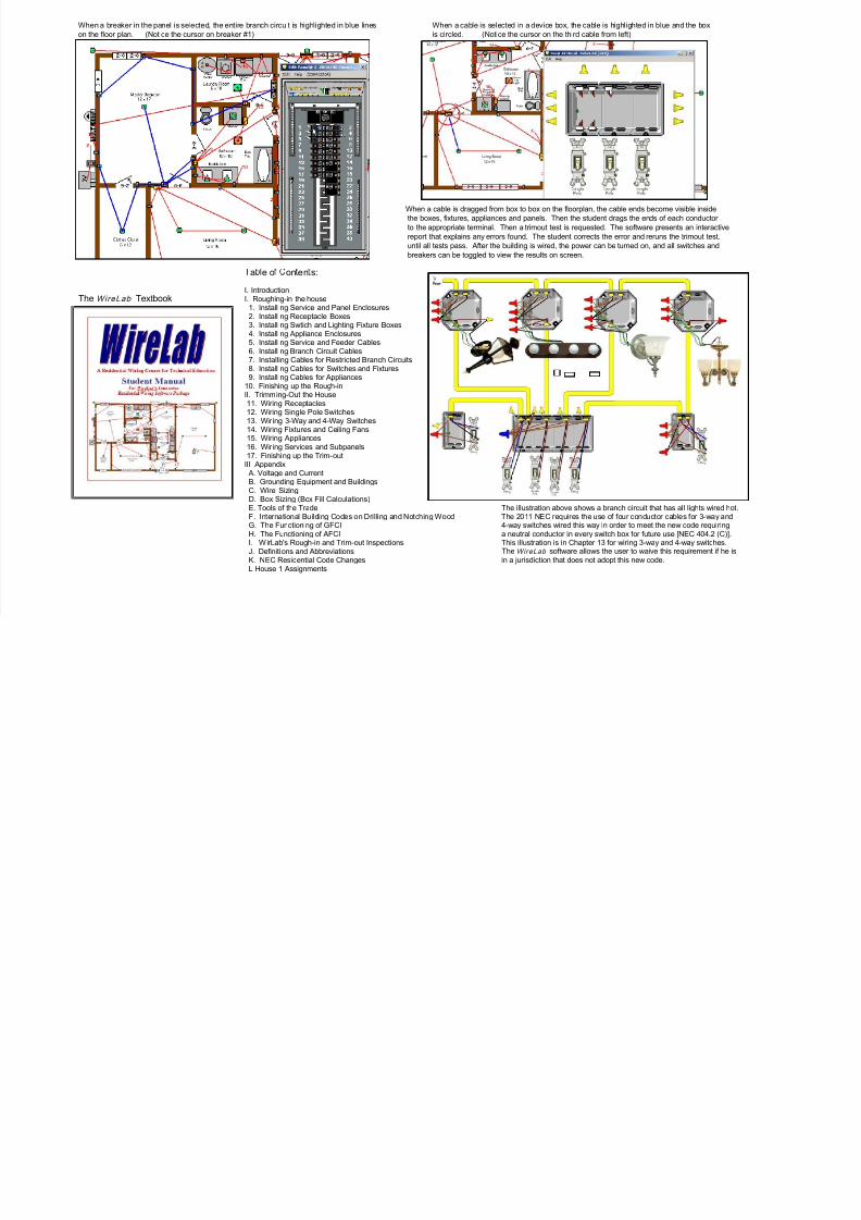
When a breaker in the panel is selected, the entire branch circuit is highlighted in blue lines When a cable is selected in a device box, the cable is highlighted in blue and the box
on the floor plan. (Notice the cursor on breaker #1) is circled. (Notice the cursor on the third cable from left)
When a cable is dragged from box to box on the floorplan, the cable ends become visible inside
the boxes, fixtures, appliances and panels. Then the student drags the ends of each conductor
to the appropriate terminal. Then a trimout test is requested. The software presents an interactive
report that explains any errors found. The student corrects the error and reruns the trimout test.
until all tests pass. After the building is wired, the power can be turned on, and all switches and
breakers can be toggled to view the results on screen.
a e o on en s:
I. Introduction
The WireLab Textbook I. Roughing-in the house1. Installing Service and Panel Enclosures2. Installing Receptacle Boxes3. Installing Swtich and Lighting Fixture Boxes4. Installing Appliance Enclosures5. Installing Service and Feeder Cables6. Installing Branch Circuit Cables7. Installing Cables for Restricted Branch Circuits8. Installing Cables for Switches and Fixtures9. Installing Cables for Appliances
10. Finishing up the Rough-in
II. Trimming-Out the House11. Wiring Receptacles12. Wiring Single Pole Switches13. Wir ing 3-Way and 4-Way Switches14. Wiring Fixtures and Ceiling Fans15. Wiring Appliances16. Wir ing Services and Subpanels17. Finishing up the Trim-out
III AppendixA. Voltage and CurrentB. Grounding Equipment and BuildingsC. Wire Sizing
D. Box Sizing (Box Fill Calculations)E. Tools of the Trade The illustration above shows a branch circuit that has all lights wired hot.F. International Building Codes on Drilling and Notching Wood The 2011 NEC requires the use of four conductor cables for 3-way andG. The Functioning of GFCI 4-way switches wired this way in order to meet the new code requiringH. The Functioning of AFCI a neutral conductor in every switch box for future use [NEC 404.2 (C)].I. WirLab's Rough-in and Trim-out Inspections This illustration is in Chapter 13 for wiring 3-way and 4-way switches.J. Definitions and Abbreviations The WireLab software allows the user to waive this requirement if he isK. NEC Residential Code Changes in a jurisdiction that does not adopt this new code.L House 1 Assignments