sizing, installation, dimensions and weights archive/air handling units/gold...the diagram shows the...
TRANSCRIPT

43
GOLD
GO
LD
www.swegon.comWe reserve the right to alter specifications. 20110601
Prerequisites for Sizing ..................................................................................................... 45GOLD RX, One-piece air handling units with rotary heat exchanger ........................... 46GOLD PX, One-piece air handling units with plate heat exchanger ............................. 86GOLD CX, One-piece air handling units with coil heat exchanger .............................. 106GOLD SD, Supply air and extract air handling units .................................................... 122
Sizing, Installation, Dimensions and Weights
Contents
The charts and tables in this documentation are intended for use as a general survey.
Exact sizing can be carried out in the ProUnit air handling
unit selection program.
44
GOLD
www.swegon.comWe reserve the right to alter specifications. 20110601
45
GOLD
GO
LD
www.swegon.comWe reserve the right to alter specifications. 20110601
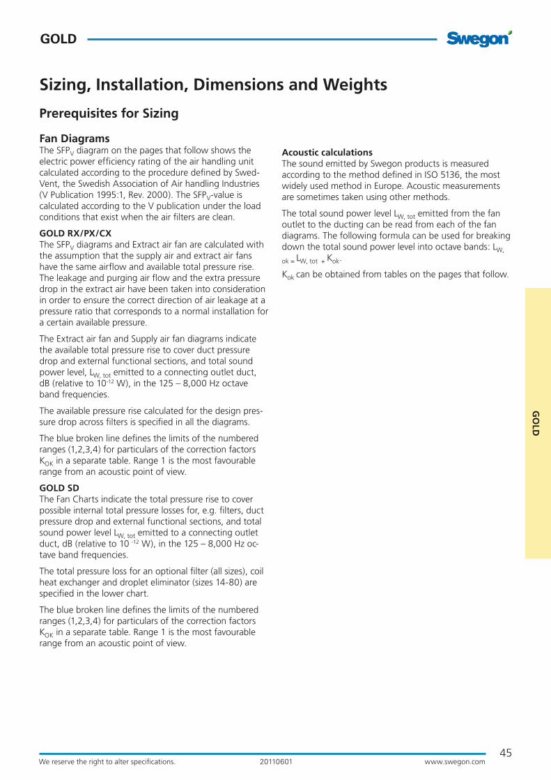
Acoustic calculationsThe sound emitted by Swegon products is measured according to the method defined in ISO 5136, the most widely used method in Europe. Acoustic measurements are sometimes taken using other methods.
The total sound power level LW, tot emitted from the fan outlet to the ducting can be read from each of the fan diagrams. The following formula can be used for breaking down the total sound power level into octave bands: LW,
ok = LW, tot + Kok.
Kok can be obtained from tables on the pages that follow.
Fan DiagramsThe SFPV diagram on the pages that follow shows the electric power efficiency rating of the air handling unit calculated according to the procedure defined by Swed-Vent, the Swedish Association of Air handling Industries (V Publication 1995:1, Rev. 2000). The SFPV-value is calculated according to the V publication under the load conditions that exist when the air filters are clean.
GOLD RX/PX/CX The SFPV diagrams and Extract air fan are calculated with the assumption that the supply air and extract air fans have the same airflow and available total pressure rise. The leakage and purging air flow and the extra pressure drop in the extract air have been taken into consideration in order to ensure the correct direction of air leakage at a pressure ratio that corresponds to a normal installation for a certain available pressure.
The Extract air fan and Supply air fan diagrams indicate the available total pressure rise to cover duct pressure drop and external functional sections, and total sound power level, LW, tot emitted to a connecting outlet duct, dB (relative to 10-12 W), in the 125 – 8,000 Hz octave band frequencies.
The available pressure rise calculated for the design pres-sure drop across filters is specified in all the diagrams.
The blue broken line defines the limits of the numbered ranges (1,2,3,4) for particulars of the correction factors KOK in a separate table. Range 1 is the most favourable range from an acoustic point of view.
GOLD SDThe Fan Charts indicate the total pressure rise to cover possible internal total pressure losses for, e.g. filters, duct pressure drop and external functional sections, and total sound power level LW, tot emitted to a connecting outlet duct, dB (relative to 10 -12 W), in the 125 – 8,000 Hz oc-tave band frequencies.
The total pressure loss for an optional filter (all sizes), coil heat exchanger and droplet eliminator (sizes 14-80) are specified in the lower chart.
The blue broken line defines the limits of the numbered ranges (1,2,3,4) for particulars of the correction factors KOK in a separate table. Range 1 is the most favourable range from an acoustic point of view.
Prerequisites for Sizing
Sizing, Installation, Dimensions and Weights

46
GOLD
www.swegon.comWe reserve the right to alter specifications. 20110601
GOLD RX, rotary heat exchanger, size 04
Sizing, Installation, Dimensions and Weights
Min. and Max. AirflowsThe flows specified refer to those that can be preset in the hand-held micro terminal. The practical flow limits are deter-mined by the external pressure drop.
* The integral attenuation of filters and rotary heat exchanger has been taken into account. ** Total sound power level emitted to the surroundings is calcu-lated as the sum of the levels in the supply air and the extract air.
Correction factors KOK , dB
Size Min. airflow (on airflow regulation)
Max. airflow
m3/h m3/s m3/h m3/s04 288 0.08 1620 0.45
Fan motor, 0.8 kW.
2.5
2.0
1.5
12
3
4
12
3
4
70dB 75
80
Lw,tot
85
70dB 75
80
Lw,tot
85
Supply air fan
Extract air fan
SFPv
Airflow, m3/s
Ava
ilab
le t
ota
l pre
ssu
re r
ise,
Pa
Airflow, m3/h
Recommended working range for commissioning.Permissible operating range when the fan is controlled to operate at a lower speed. The lower limit for the airflow when the unit is operat-ing in the airflow regulation mode; see the black broken line in the diagram. If pressure regulation is used, the airflow can be regulated to zero, however this presupposes a certain static pressure drop in the ducting (approx. 50 Pa).
The diagram shows the air handling unit including the end connection panels.
The lower limit for the airflow when the unit is operating in the airflow regulation mode.
Range in the
diagram
Octave band, No. / mid-frequency, Hz
Sound path 1 2 3 4 5 6 7 8
63 125 250 500 1000 2000 4000 8000
To outlet duct 1 -1 -6 -6 -8 -7 -7 -12 -152 -1 -5 -8 -8 -7 -9 -13 -163 -1 -2 -6 -15 -14 -16 -22 -254 -2 -3 -5 -13 -13 -14 -20 -25
To inlet duct* 1 -6 -9 -12 -22 -31 -33 -38 -372 -7 -10 -17 -18 -29 -31 -37 -383 -6 -4 -14 -27 -35 -39 -44 -434 -7 -5 -12 -22 -34 -36 -42 -43
To air handling unit surroun-dings**
1 -12 -20 -29 -29 -40 -40 -46 -462 -12 -19 -31 -29 -40 -42 -47 -473 -12 -16 -29 -36 -47 -49 -56 -564 -13 -17 -28 -34 -46 -47 -54 -56

47
GOLD
GO
LD
www.swegon.comWe reserve the right to alter specifications. 20110601
52 50 5052 J
GOLD RX, rotary heat exchanger, size 04
Sizing, Installation, Dimensions and Weights
Size A B C D F G H J L Ø Weight, kg
04 750 825 240 345 230 460 920 561 1500 315 243
Power connection1-phase, 3-wire, 230 V -10/+15%, 50 Hz, 10 A or 3-phase, 5-wire, 400 V -10/+15%, 50 Hz, 10 A
Rated data per fanMotor shaft power: 0.8 kW (0.41 kW)* motor control system, 1 x 230 V, 50 Hz *The motor control system limits the power of the take-off to the value specified.
Clear Space for InspectionA clear space of 800 mm must be provided in front of the unit and at least 200 mm must be provided above the junction hood.
Right-hand version
Left-hand version
Delivery and Transport within the SiteThe GOLD RX 04 is produced in one single variant. All of its components are arranged at their given physical location inside the air handling unit. The air handling unit is supplied on a wooden pallet.
Base beams/Stand/FoundationThe design makes it necessary to mount the GOLD RX 04 on base beams, a stand or some other form of foundation. Other-wise it will not be possible to open the inspection doors.
Prefitted base beams are obtainable as optional equipment; a separately supplied stand is available as an accessory.
Installation/duct connection optionsA: Specify right-hand or left-hand version when ordering! The air handling unit is supplied with all the end connection panels, the version can be changed at the building site by making a simple adjustment in the control equipment.
B: The air handling unit can be installed up ended (does not apply to units installed outdoors).
Outside air Supply air Extract air Exhaust air
Power connection
Base beams are optional.
* The air handling unit is supplied without end connection panel if a duct accessory housed in an insulated casing will be connected.

48
GOLD
www.swegon.comWe reserve the right to alter specifications. 20110601
GOLD RX Top, rotary heat exchanger, size 04
Sizing, Installation, Dimensions and Weights
Min. and Max. AirflowsThe flows specified refer to those that can be preset in the hand-held micro terminal. The practical flow limits are determined by the external pressure drop.
* The integral attenuation of filters and rotary heat exchanger has been taken into account.** Total sound power level emitted to the surroundings is calculated as the sum of the levels in the supply air and the extract air.
Correction factors KOK , dB. Fan in upper level.
Size Min. airflow (on airflow regulation)
Max. airflow
m3/h m3/s m3/h m3/s04 288 0,08 1620 0,45
Fan motor, 0.8 kW. Left-hand version.
70
75
65dBLw,tot
70 7565dBLw,tot
2.5
2.0
1.5
123
4
1 234
80
8085
Supply air fan
Extract air fan
SFPv
Airflow, m3/s
Ava
ilab
le t
ota
l pre
ssu
re r
ise,
Pa
Airflow, m3/h
Recommended working range for commissioning.Permissible operating range when the fan is controlled to operate at a lower speed. The lower limit for the airflow when the unit is operat-ing in the airflow regulation mode; see the black broken line in the diagram. If pressure regulation is used, the airflow can be regulated to zero, however this presupposes a certain static pressure drop in the ducting (approx. 50 Pa).
The diagram shows the air handling unit including the end connection panels.The lower limit for the airflow when the unit is operating in the airflow regulation mode.
Fan motor, 0.8 kW. Right-hand version.
7570dBLw,tot
2.5
2.0
1.5
12
3
4
123
48085
75
70dBLw,tot
80
Supply air fan
Extract air fan
SFPv
Airflow, m3/s
Ava
ilab
le t
ota
l pre
ssu
re r
ise,
Pa
Airflow, m3/h
Range in the
diagram
Octave band, No. / mid-frequency, Hz
Sound path 1 2 3 4 5 6 7 8
63 125 250 500 1000 2000 4000 8000
To outlet duct 1 4 -1 -6 -15 -24 -29 -41 -322 4 -1 -9 -14 -22 -27 -40 -363 1 -1 -10 -23 -32 -37 -49 -414 3 -1 -7 -17 -27 -32 -45 -42
To inlet duct* 1 -1 -5 -11 -24 -39 -45 -49 -372 -1 -7 -13 -21 -38 -44 -56 -473 -5 -6 -16 -34 -48 -55 -61 -484 -5 -6 -11 -25 -42 -50 -62 -53
To air handling unit surroun-dings**
1 -7 -15 -29 -36 -57 -62 -75 -632 -7 -15 -32 -35 -55 -60 -74 -673 -10 -15 -33 -44 -65 -70 -83 -724 -8 -15 -30 -38 -60 -65 -79 -73
Range in the
diagram
Octave band, No. / mid-frequency, Hz
Sound path 1 2 3 4 5 6 7 8
63 125 250 500 1000 2000 4000 8000
To outlet duct 1 6 -2 -5 -13 -21 -26 -35 -242 14 -1 -8 -14 -22 -26 -39 -343 4 -1 -8 -21 -31 -35 -46 -364 7 -2 -4 -15 -26 -31 -45 -41
To inlet duct* 1 1 -6 -10 -23 -36 -42 -43 -292 5 -5 -14 -27 -37 -46 -54 -433 -1 -6 -13 -34 -46 -53 -58 -434 2 -2 -9 -29 -39 -49 -59 -48
To air handling unit surroun-dings**
1 -5 -16 -28 -34 -54 -59 -69 -552 3 -15 -31 -35 -55 -59 -73 -653 -7 -15 -31 -42 -64 -68 -80 -674 -4 -16 -27 -36 -59 -64 -79 -72
Correction factors, KOK , dB. Fan in lower level.
49
GOLD
GO
LD
www.swegon.comWe reserve the right to alter specifications. 20110601
50 50J5252
GOLD RX Top, rotary heat exchanger, size 04
Sizing, Installation, Dimensions and Weights
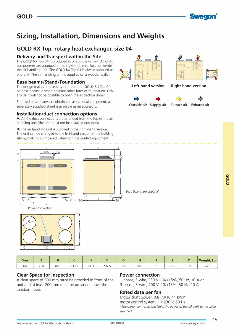
Base beams are optional.
Size A B C D F G H J L Ø Weight, kg
04 750 825 233,5 1033 237,5 350 920 561 1500 315 247
Power connection1-phase, 3-wire, 230 V -10/+15%, 50 Hz, 10 A or 3-phase, 5-wire, 400 V -10/+15%, 50 Hz, 10 A
Rated data per fanMotor shaft power: 0.8 kW (0.41 kW)* motor control system, 1 x 230 V, 50 Hz *The motor control system limits the power of the take-off to the value
specified.
Clear Space for InspectionA clear space of 800 mm must be provided in front of the unit and at least 200 mm must be provided above the junction hood.
Delivery and Transport within the SiteThe GOLD RX Top 04 is produced in one single variant. All of its components are arranged at their given physical location inside the air handling unit. The GOLD RX Top 04 is always supplied as one unit. The air handling unit is supplied on a wooden pallet.
Base beams/Stand/FoundationThe design makes it necessary to mount the GOLD RX Top 04 on base beams, a stand or some other form of foundation. Oth-erwise it will not be possible to open the inspection doors.
Prefitted base beams are obtainable as optional equipment; a separately supplied stand is available as an accessory.
Installation/duct connection optionsA: All the duct connections are arranged from the top of the air handling unit (the unit must not be installed outdoors).
B: The air handling unit is supplied in the right-hand version. The unit can be changed to the left-hand version at the building site by making a simple adjustment in the control equipment.
Outside air Supply air Extract air Exhaust air
Power connection
Left-hand version Right-hand version

50
GOLD
www.swegon.comWe reserve the right to alter specifications. 20110601
Min. and Max. AirflowsThe flows specified refer to those that can be preset in the hand-held micro terminal. The practical flow limits are deter-mined by the external pressure drop.
Correction factors KOK , dB
GOLD RX, rotary heat exchanger, size 05
Sizing, Installation, Dimensions and Weights
2.52.01.5
12
3
4
123
4
70dB 75 80Lw,tot
85
70dB 75 80Lw,tot
8590
90
Supply air fan
Extract air fan
SFPv
Airflow, m3/s
Ava
ilab
le t
ota
l pre
ssu
re r
ise,
Pa
Airflow, m3/h
Recommended working range for commissioning.Permissible operating range when the fan is controlled to operate at a lower speed. The lower limit for the airflow when the unit is operat-ing in the airflow regulation mode; see the black broken line in the diagram. If pressure regulation is used, the airflow can be regulated to zero, however this presupposes a certain static pressure drop in the ducting (approx. 50 Pa).
The lower limit for the airflow when the unit is operating in the airflow regulation mode.
Size Min. airflow (on airflow regulation)
Max. airflow
m3/h m3/s m3/h m3/s05 288 0.08 2340 0.65
* The integral attenuation of filters and rotary heat exchanger has been taken into account. ** Total sound power level emitted to the surroundings is calcu-lated as the sum of the levels in the supply air and the extract air.
Range in the
diagram
Octave band, No. / mid-frequency, Hz
Sound path 1 2 3 4 5 6 7 8
63 125 250 500 1000 2000 4000 8000
To outlet duct 1 -1 -6 -6 -8 -7 -7 -12 -152 -1 -5 -8 -8 -7 -9 -13 -163 -1 -2 -6 -15 -14 -16 -22 -254 -2 -3 -5 -13 -13 -14 -20 -25
To inlet duct* 1 -6 -9 -12 -22 -31 -33 -38 -372 -7 -10 -17 -18 -29 -31 -37 -383 -6 -4 -14 -27 -35 -39 -44 -434 -7 -5 -12 -22 -34 -36 -42 -43
To unit’s sur-roundings**
1 -12 -20 -29 -29 -40 -40 -46 -462 -12 -19 -31 -29 -40 -42 -47 -473 -12 -16 -29 -36 -47 -49 -56 -564 -13 -17 -28 -34 -46 -47 -54 -56
The diagram shows the air handling unit including the end connection panels.
Fan motor: 0.8 kW, capacity variant 1 Fan motor: 1.15 kW, capacity variant 2
2.52.01.5
12
3
4
123
4
70dB 75 80 85Lw,tot
70dB 75 80Lw,tot
9095
85
9095 Supply air fan
Extract air fan
SFPv
Airflow, m3/s
Ava
ilab
le t
ota
l pre
ssu
re r
ise,
Pa
51
GOLD
GO
LD
www.swegon.comWe reserve the right to alter specifications. 20110601
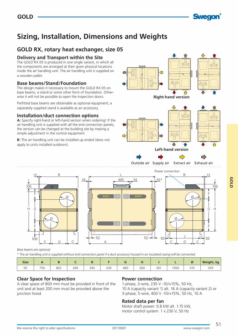
Clear Space for InspectionA clear space of 800 mm must be provided in front of the unit and at least 200 mm must be provided above the junction hood.
Right-hand version
Left-hand version
Delivery and Transport within the SiteThe GOLD RX 05 is produced in one single variant, in which all the components are arranged at their given physical locations inside the air handling unit. The air handling unit is supplied on a wooden pallet.
Base beams/Stand/FoundationThe design makes it necessary to mount the GOLD RX 05 on base beams, a stand or some other form of foundation. Other-wise it will not be possible to open the inspection doors.
Prefitted base beams are obtainable as optional equipment; a separately supplied stand is available as an accessory.
Installation/duct connection optionsA: Specify right-hand or left-hand version when ordering! If the air handling unit is supplied with all the end connection panels, the version can be changed at the building site by making a simple adjustment in the control equipment.
B: The air handling unit can be installed up ended (does not apply to units installed outdoors).
Outside air Supply air Extract air Exhaust air
GOLD RX, rotary heat exchanger, size 05
Sizing, Installation, Dimensions and Weights
Size A B C D F G H J L Ø Weight, kg
05 750 825 240 345 230 460 920 561 1500 315 243
Power connection1-phase, 3-wire, 230 V -10/+15%, 50 Hz, 10 A (capacity variant 1) alt. 16 A (capacity variant 2) or 3-phase, 5-wire, 400 V -10/+15%, 50 Hz, 10 A
Rated data per fanMotor shaft power: 0.8 kW alt. 1.15 kW, motor control system: 1 x 230 V, 50 Hz
52 50 5052 J
Power connection
Base beams are optional.
* The air handling unit is supplied without end connection panel if a duct accessory housed in an insulated casing will be connected.

52
GOLD
www.swegon.comWe reserve the right to alter specifications. 20110601
GOLD RX Top, rotary heat exchanger, size 05
Sizing, Installation, Dimensions and Weights
Fan motor, 0.8 kW. Left-hand version.
70 75Lw,tot
70 75 8065dB
2.52.01.5
123
4
1
23
4
8085
8590
Lw,tot
65dB
Supply air fan
Extract air fan
SFPv
Airflow, m3/s
Ava
ilab
le t
ota
l pre
ssu
re r
ise,
Pa
Airflow, m3/h
Fan motor, 0.8 kW. Right-hand version.
2.52.01.5
1
23
4
1
23
4
75 80Lw,tot 70dB
75Lw,tot 70dB
8590
8085
Supply air fan
Extract air fan
SFPv
Airflow, m3/s
Ava
ilab
le t
ota
l pre
ssu
re r
ise,
Pa
Airflow, m3/h
Min. and Max. AirflowsThe flows specified refer to those that can be preset in the hand-held micro terminal. The practical flow limits are determined by the external pressure drop.
* The integral attenuation of filters and rotary heat exchanger has been taken into account.** Total sound power level emitted to the surroundings is calculated as the sum of the levels in the supply air and the extract air.
Size Min. airflow (on airflow regulation)
Max. airflow
m3/h m3/s m3/h m3/s05 288 0,08 2340 0,65
Range in the
diagram
Octave band, No. / mid-frequency, Hz
Sound path 1 2 3 4 5 6 7 8
63 125 250 500 1000 2000 4000 8000
To outlet duct 1 4 -1 -6 -15 -24 -29 -41 -322 4 -1 -9 -14 -22 -27 -40 -363 1 -1 -10 -23 -32 -37 -49 -414 3 -1 -7 -17 -27 -32 -45 -42
To inlet duct* 1 -1 -5 -11 -24 -39 -45 -49 -372 -1 -7 -13 -21 -38 -44 -56 -473 -5 -6 -16 -34 -48 -55 -61 -484 -5 -6 -11 -25 -42 -50 -62 -53
To air handling unit surroun-dings**
1 -7 -15 -29 -36 -57 -62 -75 -632 -7 -15 -32 -35 -55 -60 -74 -673 -10 -15 -33 -44 -65 -70 -83 -724 -8 -15 -30 -38 -60 -65 -79 -73
Range in the
diagram
Octave band, No. / mid-frequency, Hz
Sound path 1 2 3 4 5 6 7 8
63 125 250 500 1000 2000 4000 8000
To outlet duct 1 6 -2 -5 -13 -21 -26 -35 -242 14 -1 -8 -14 -22 -26 -39 -343 4 -1 -8 -21 -31 -35 -46 -364 7 -2 -4 -15 -26 -31 -45 -41
To inlet duct* 1 1 -6 -10 -23 -36 -42 -43 -292 5 -5 -14 -27 -37 -46 -54 -433 -1 -6 -13 -34 -46 -53 -58 -434 2 -2 -9 -29 -39 -49 -59 -48
To air handling unit surroun-dings**
1 -5 -16 -28 -34 -54 -59 -69 -552 3 -15 -31 -35 -55 -59 -73 -653 -7 -15 -31 -42 -64 -68 -80 -674 -4 -16 -27 -36 -59 -64 -79 -72
Correction factors, KOK , dB. Fan in upper level.
Correction factors, KOK , dB. Fan in lower level
Recommended working range for commissioning.Permissible operating range when the fan is controlled to operate at a lower speed. The lower limit for the airflow when the unit is operat-ing in the airflow regulation mode; see the black broken line in the diagram. If pressure regulation is used, the airflow can be regulated to zero, however this presupposes a certain static pressure drop in the ducting (approx. 50 Pa).
The diagram shows the air handling unit including the end connection panels.The lower limit for the airflow when the unit is operating in the airflow regulation mode.

53
GOLD
GO
LD
www.swegon.comWe reserve the right to alter specifications. 20110601
GOLD RX Top, rotary heat exchanger, size 05
Sizing, Installation, Dimensions and Weights
Power connection1-phase, 3-wire, 230 V -10/+15%, 50 Hz, 10 A or 3-phase, 5-wire, 400 V -10/+15%, 50 Hz, 10 A
Rated data per fanMotor shaft power 0.8 kW motor control system, 1 x 230 V, 50 Hz
Size A B C D F G H J L Ø Weight, kg
05 750 825 233,5 1033 237,5 350 920 561 1500 315 247
Clear Space for InspectionA clear space of 800 mm must be provided in front of the unit and at least 200 mm must be provided above the junction hood.
Delivery and Transport within the SiteThe COMPACT Top 05 unit is produced in one variant in which all the components are arranged at their given physical location inside the unit. The GOLD RX Top 05 is always supplied as one unit. The air handling unit is supplied on a wooden pallet.
Base beams/Stand/FoundationThe design makes it necessary to mount the GOLD RX Top 05 on base beams, a stand or some other form of foundation. Oth-erwise it will not be possible to open the inspection doors.
Prefitted base beams are obtainable as optional equipment; a separately supplied stand is available as an accessory.
Installation/duct connection optionsA: All the duct connections are arranged from the top of the air handling unit (the unit must not be installed outdoors).
B: The air handling unit is supplied in the right-hand version. The unit can be changed to the left-hand version at the building site by making a simple adjustment in the control equipment.
Outside air Supply air Extract air Exhaust air
Left-hand version Right-hand version
50 50J5252
Base beams are optional.
Power connection

54
GOLD
www.swegon.comWe reserve the right to alter specifications. 20110601
Min. and Max. AirflowsThe flows specified refer to those that can be preset in the hand-held micro terminal. The practical flow limits are deter-mined by the external pressure drop.
Correction factors KOK , dB
GOLD RX, rotary heat exchanger, size 08
Sizing, Installation, Dimensions and Weights
2.5
2.01.5
75dB 80 85Lw,tot
85
75dB 80 85Lw,tot
85
1
23
4
1
23
4
Supply air fan
Extract air fan
SFPv
Airflow, m3/s
Ava
ilab
le t
ota
l pre
ssu
re r
ise,
Pa
Airflow, m3/h
Recommended working range for commissioning.Permissible operating range when the fan is controlled to operate at a lower speed. The lower limit for the airflow when the unit is operat-ing in the airflow regulation mode; see the black broken line in the diagram. If pressure regulation is used, the airflow can be regulated to zero, however this presupposes a certain static pressure drop in the ducting (approx. 50 Pa).
The lower limit for the airflow when the unit is operating in the airflow regulation mode.
Size Min. airflow (on airflow regulation)
Max. airflow
m3/h m3/s m3/h m3/s08 720 0.20 3600 1.00
* The integral attenuation of filters and rotary heat exchanger has been taken into account. ** Total sound power level emitted to the surroundings is calcu-lated as the sum of the levels in the supply air and the extract air.
Range in the
diagram
Octave band, No. / mid-frequency, Hz
Sound path 1 2 3 4 5 6 7 8
63 125 250 500 1000 2000 4000 8000
To outlet duct 1 -1 -6 -6 -8 -7 -7 -12 -152 -1 -5 -8 -8 -7 -9 -13 -163 -1 -2 -6 -15 -14 -16 -22 -254 -2 -3 -5 -13 -13 -14 -20 -25
To inlet duct* 1 -6 -9 -12 -22 -31 -33 -38 -372 -7 -10 -17 -18 -29 -31 -37 -383 -6 -4 -14 -27 -35 -39 -44 -434 -7 -5 -12 -22 -34 -36 -42 -43
To air handling unit surroun-dings**
1 -12 -20 -29 -29 -40 -40 -46 -462 -12 -19 -31 -29 -40 -42 -47 -473 -12 -16 -29 -36 -47 -49 -56 -564 -13 -17 -28 -34 -46 -47 -54 -56
Fan motor: 1.15 kW, capacity variant 1 Fan motor: 1.6 kW, capacity variant 2
2.5
2.01.5
75dB 80 85Lw,tot
75dB 80 85Lw,tot
1
23
4
1
23
4
Supply air fan
Extract air fan
SFPv
Airflow, m3/s
Ava
ilab
le t
ota
l pre
ssu
re r
ise,
Pa
Airflow, m3/h
The diagram shows the air handling unit including the end connection panels.

55
GOLD
GO
LD
www.swegon.comWe reserve the right to alter specifications. 20110601
GOLD RX, rotary heat exchanger, size 08
Sizing, Installation, Dimensions and Weights
Size A B C D F G H J L Ø Weight, kg
08 800 995 277,5 440 271 543 1085 730 1600 400 309
Clear Space for InspectionA clear space of 800 mm must be provided in front of the unit and at least 200 mm must be provided above the junction hood.
Right-hand version
Left-hand version
Delivery and Transport within the SiteThe GOLD RX 08 is produced in one single variant, in which all the components are arranged at their given physical locations inside the air handling unit. The air handling unit is supplied on a wooden pallet.
Base beams/Stand/FoundationThe design makes it necessary to mount the GOLD RX 08 on base beams, a stand or some other form of foundation. Other-wise it will not be possible to open the inspection doors.
Prefitted base beams are obtainable as optional equipment; a separately supplied stand is available as an accessory.
Installation/duct connection optionsA: Specify right-hand or left-hand version when ordering! If the air handling unit is supplied with all the end connection panels, the version can be changed at the building site by making a simple adjustment in the control equipment.
B: The air handling unit can be installed up ended (does not apply to units installed outdoors).
Outside air Supply air Extract air Exhaust air
Power connectionCapacity variant 1: 1-phase, 3-wire, 230 V -10/+15%, 50 Hz, 16 A or 3-phase, 5-wire, 400 V -10/+15%, 50 Hz, 10 A Capacity variant 2: 3-phase, 5-wire, 400 V -10/+15%, 50 Hz, 10 ARated data per fanCapacity variant 1: Motor shaft power: 1.15 kW, motor control system: 1 x 230 V, 50 Hz Capacity variant 2: Motor shaft power: 1.6 kW, motor control system: 3 x 400 V, 50 Hz
52 50 5052 J
Power connection
Base beams are optional.
* The air handling unit is supplied without end connection panel if a duct accessory housed in an insulated casing will be connected.
56
GOLD
www.swegon.comWe reserve the right to alter specifications. 20110601
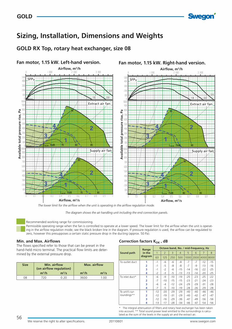
Min. and Max. AirflowsThe flows specified refer to those that can be preset in the hand-held micro terminal. The practical flow limits are deter-mined by the external pressure drop.
GOLD RX Top, rotary heat exchanger, size 08
Sizing, Installation, Dimensions and Weights
Size Min. airflow (on airflow regulation)
Max. airflow
m3/h m3/s m3/h m3/s08 720 0.20 3600 1.00
Fan motor, 1.15 kW. Left-hand version.
75 8070dBLw,tot
2.5
2.01.5
85
75 80 8570dBLw,tot
90
1
23
1
2
3
4
4
Supply air fan
Extract air fan
SFPv
Airflow, m3/s
Ava
ilab
le t
ota
l pre
ssu
re r
ise,
Pa
Airflow, m3/h
Recommended working range for commissioning.Permissible operating range when the fan is controlled to operate at a lower speed. The lower limit for the airflow when the unit is operat-ing in the airflow regulation mode; see the black broken line in the diagram. If pressure regulation is used, the airflow can be regulated to zero, however this presupposes a certain static pressure drop in the ducting (approx. 50 Pa).
The diagram shows the air handling unit including the end connection panels.
The lower limit for the airflow when the unit is operating in the airflow regulation mode.
Fan motor, 1.15 kW. Right-hand version.
2.52.01.5
80 8575dBLw,tot
1
2
3
4
1
2
3
4
90
80
85
Lw,tot 75dB
Supply air fan
Extract air fan
SFPv
Airflow, m3/s
Ava
ilab
le t
ota
l pre
ssu
re r
ise,
Pa
Airflow, m3/h
Correction factors KOK , dB
* The integral attenuation of filters and rotary heat exchanger has been taken into account. ** Total sound power level emitted to the surroundings is calcu-lated as the sum of the levels in the supply air and the extract air.
Range in the
diagram
Octave band, No. / mid-frequency, Hz
Sound path 1 2 3 4 5 6 7 8
63 125 250 500 1000 2000 4000 8000
To outlet duct 1 -1 -6 -6 -8 -7 -7 -12 -152 -1 -5 -8 -8 -7 -9 -13 -163 -1 -2 -6 -15 -14 -16 -22 -254 -2 -3 -5 -13 -13 -14 -20 -25
To inlet duct* 1 -6 -9 -10 -19 -25 -23 -25 -222 -7 -10 -15 -15 -23 -21 -24 -233 -6 -4 -12 -24 -29 -29 -31 -284 -7 -5 -10 -19 -28 -26 -29 -28
To unit’s sur-roundings**
1 -12 -20 -29 -29 -40 -40 -46 -462 -12 -19 -31 -29 -40 -42 -47 -473 -12 -16 -29 -36 -47 -49 -56 -564 -13 -17 -28 -34 -46 -47 -54 -56

57
GOLD
GO
LD
www.swegon.comWe reserve the right to alter specifications. 20110601
GOLD RX Top, rotary heat exchanger, size 08
Sizing, Installation, Dimensions and Weights
Power connection1-phase, 3-wire, 230 V -10/+15%, 50 Hz, 16 A or 3-phase, 5-wire, 400 V -10/+15%, 50 Hz, 10 A
Rated data per fanMotor shaft power 1.15 kW motor control system, 1 x 230 V, 50 Hz
Size A B C D F G H J L Ø Weight, kg
08 800 995 276 1048 280 435 1085 730 1600 400 310
Clear Space for InspectionA clear space of 900 mm must be provided in front of the unit and at least 200 mm must be provided above the junction hood.
Delivery and Transport within the SiteThe GOLD RX Top unit is produced in one variant in which all the components are arranged at their given physical location inside the unit. The GOLD RX Top 08 is always supplied as one unit. The air handling unit is supplied on a wooden pallet.
Base beams/Stand/FoundationThe design makes it necessary to mount the GOLD RX Top 08 on base beams, a stand or some other form of foundation. Oth-erwise it will not be possible to open the inspection doors.
Prefitted base beams are obtainable as optional equipment; a separately supplied stand is available as an accessory.
Installation/duct connection optionsA: All the duct connections are arranged from the top of the air handling unit (the unit must not be installed outdoors).
B: The air handling unit is supplied in the right-hand version. The unit can be changed to the left-hand version at the building site by making a simple adjustment in the control equipment.
Outside air Supply air Extract air Exhaust air
Left-hand version Right-hand version
50 50J5252
Base beams are optional.
Power connection

58
GOLD
www.swegon.comWe reserve the right to alter specifications. 20110601
Min. and Max. AirflowsThe flows specified refer to those that can be preset in the hand-held micro terminal. The practical flow limits are deter-mined by the external pressure drop.
Correction factors KOK , dB
GOLD RX, rotary heat exchanger, size 12
Sizing, Installation, Dimensions and Weights
2.5
2.01.5
75dB 80Lw,tot
123
123
90
75dB 80 85Lw,tot
90
85
Supply air fan
Extract air fan
SFPv
Airflow, m3/s
Ava
ilab
le t
ota
l pre
ssu
re r
ise,
Pa
Airflow, m3/h
Recommended working range for commissioning.Permissible operating range when the fan is controlled to operate at a lower speed. The lower limit for the airflow when the unit is operat-ing in the airflow regulation mode; see the black broken line in the diagram. If pressure regulation is used, the airflow can be regulated to zero, however this presupposes a certain static pressure drop in the ducting (approx. 50 Pa).
The lower limit for the airflow when the unit is operating in the airflow regulation mode.
Size Min. airflow (on airflow regulation)
Max. airflow
m3/h m3/s m3/h m3/s12 720 0.20 5040 1.40
* The integral attenuation of filters and rotary heat exchanger has been taken into account. ** Total sound power level emitted to the surroundings is calcu-lated as the sum of the levels in the supply air and the extract air.
Range in the
diagram
Octave band, No. / mid-frequency, Hz
Sound path 1 2 3 4 5 6 7 8
63 125 250 500 1000 2000 4000 8000
To outlet duct 1 -1 -6 -6 -8 -7 -7 -12 -152 -1 -5 -8 -8 -7 -9 -13 -163 -1 -2 -6 -15 -14 -16 -22 -25
To inlet duct* 1 -6 -9 -12 -22 -31 -33 -38 -372 -7 -10 -17 -18 -29 -31 -37 -383 -6 -4 -14 -27 -35 -39 -44 -43
To air handling unit surroun-dings**
1 -12 -20 -29 -29 -40 -40 -46 -462 -12 -19 -31 -29 -40 -42 -47 -473 -12 -16 -29 -36 -47 -49 -56 -56
Fan motor: 1.6 kW, capacity variant 1 Fan motor: 2.4 kW, capacity variant 2
2.5
2.01.5
75dB 80 85Lw,tot
90
90
75dB 80 85Lw,tot
90
90
1
2
3
1
2
3
Supply air fan
Extract air fan
SFPv
Airflow, m3/s
Ava
ilab
le t
ota
l pre
ssu
re r
ise,
Pa
Airflow, m3/h
The diagram shows the air handling unit including the end connection panels.

59
GOLD
GO
LD
www.swegon.comWe reserve the right to alter specifications. 20110601
5250 50
52
16
J50 50J
K K
GOLD RX, rotary heat exchanger, size 12
Sizing, Installation, Dimensions and Weights
Delivery and Transport within the SiteThe GOLD RX 12 is always supplied as one unit. The air han-dling unit can be split into three sections to facilitate transport-ing it within the building site.
The three sections are joined together by bolts and the electri-cal and control cables have quick connectors.
The air handling unit is delivered on wooden beams.
Duct connection optionsA: Specify right-hand or left-hand version when ordering! If the air handling unit is supplied with all the end connection panels, the version can be changed at the building site by making a simple adjustment in the control equipment.
B: The arrangement of the functional sections can be vertically reversed. Specify this by selecting fan arrangement 1 or 2 when placing orders!
Right-hand version
Left-hand version
Fan arrangement 1 Fan arrangement 2
Fan arrangement 1 Fan arrangement 2
Outside air Supply air Extract air Exhaust air
Power connection
The unit can be divided into three sections at the building site.Dimensions: See A and D in the table above.Weight: A = 178 kg, D = 162 kg.
Division into sections for transport
A AD+19 mm
Size A B C D F G H J K L Ø Weight, kg
12 655 1199 324 550 324 647 1295 935 551 1860 500 518
The dimension print shows the connection configuration for fan arrangement 1. For fan arrangement 2 the connections are mirror-inverted.
* The air handling unit is supplied without end connection panel if a duct accessory housed in an insulated casing will be connected.
Clear space for inspectionA clear space of 800 mm should be provided in front of the unit and at least 200 mm should be provided above the junction hood.
Power connection3-phase, 5-wire, 400 V -10/+15%, 50 Hz, 10 A
Rated data per fanMotor shaft power: 1.6 kW alt. 2.4 kW, motor control system: 3 x 400 V, 50 Hz
60
GOLD
www.swegon.comWe reserve the right to alter specifications. 20110601
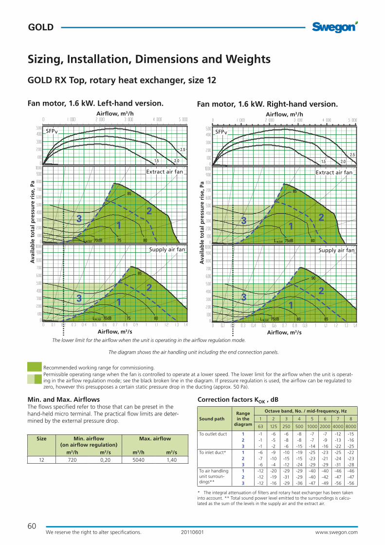
Min. and Max. AirflowsThe flows specified refer to those that can be preset in the hand-held micro terminal. The practical flow limits are deter-mined by the external pressure drop.
GOLD RX Top, rotary heat exchanger, size 12
Sizing, Installation, Dimensions and Weights
Size Min. airflow (on airflow regulation)
Max. airflow
m3/h m3/s m3/h m3/s12 720 0,20 5040 1,40
Fan motor, 1.6 kW. Left-hand version.
70dB 75Lw,tot 80
85
70dB 75Lw,tot 80
85
2.5
2.01.5
12
3
12
3
Supply air fan
Extract air fan
SFPv
Airflow, m3/s
Ava
ilab
le t
ota
l pre
ssu
re r
ise,
Pa
Airflow, m3/h
Recommended working range for commissioning.Permissible operating range when the fan is controlled to operate at a lower speed. The lower limit for the airflow when the unit is operat-ing in the airflow regulation mode; see the black broken line in the diagram. If pressure regulation is used, the airflow can be regulated to zero, however this presupposes a certain static pressure drop in the ducting (approx. 50 Pa).
The diagram shows the air handling unit including the end connection panels.
The lower limit for the airflow when the unit is operating in the airflow regulation mode.
Fan motor, 1.6 kW. Right-hand version.
2.5
2.01.5
123
12
3
75dB 80Lw,tot 85
75dB 80Lw,tot
85
90
Supply air fan
Extract air fan
SFPv
Airflow, m3/s
Ava
ilab
le t
ota
l pre
ssu
re r
ise,
Pa
Airflow, m3/h
Correction factors KOK , dB
* The integral attenuation of filters and rotary heat exchanger has been taken into account. ** Total sound power level emitted to the surroundings is calcu-lated as the sum of the levels in the supply air and the extract air.
Range in the
diagram
Octave band, No. / mid-frequency, Hz
Sound path 1 2 3 4 5 6 7 8
63 125 250 500 1000 2000 4000 8000
To outlet duct 1 -1 -6 -6 -8 -7 -7 -12 -152 -1 -5 -8 -8 -7 -9 -13 -163 -1 -2 -6 -15 -14 -16 -22 -25
To inlet duct* 1 -6 -9 -10 -19 -25 -23 -25 -222 -7 -10 -15 -15 -23 -21 -24 -233 -6 -4 -12 -24 -29 -29 -31 -28
To air handling unit surroun-dings**
1 -12 -20 -29 -29 -40 -40 -46 -462 -12 -19 -31 -29 -40 -42 -47 -473 -12 -16 -29 -36 -47 -49 -56 -56

61
GOLD
GO
LD
www.swegon.comWe reserve the right to alter specifications. 20110601
GOLD RX Top, rotary heat exchanger, size 12
Sizing, Installation, Dimensions and Weights
Delivery and Transport within the SiteThe GOLD RX Top unit is produced in one variant in which all the components are arranged at their given physical location inside the unit. The GOLD RX Top 12 is always supplied as one unit. The air handling unit can be split into three sections to facilitate transporting it within the building site.
The three sections are joined together by bolts and the electri-cal and control cables have quick connectors.
The air handling unit is delivered on wooden beams.
Duct connection optionsA: All the duct connections are arranged from the top of the air handling unit (the unit must not be installed outdoors).
B: The air handling unit is supplied in the right-hand version. The unit can be changed to the left-hand version at the building site by making a simple adjustment in the control equipment.
Left-hand version Right-hand version
Outside air Supply air Extract air Exhaust air
Clear Space for InspectionA clear space of 800 mm must be provided in front of the unit and at least 200 mm must be provided above the junction hood.
Power connection3-phase, 5-wire, 400 V -10/+15%, 50 Hz, 10 A
Rated data per fanMotor shaft power: 1.6 kW, motor control system, 3 x 400 V, 50 Hz
The unit can be divided into three sections at the building site.Dimensions: See A and D in the table above.Weight: A = 171 kg, D = 162 kg.A AD+19 mm
Size A B C D F G H J K L Ø Weight, kg
12 655 1199 332 550 333 533 1295 935 1196 1860 500 504
5250 50
52
16 16
J
C K C
Power connection
Division into sections for transport

62
GOLD
www.swegon.comWe reserve the right to alter specifications. 20110601
GOLD RX, rotary heat exchanger, size 14
Sizing, Installation, Dimensions and Weights
Min. and Max. AirflowsThe flows specified refer to those that can be preset in the hand-held micro terminal. The practical flow limits are deter-mined by the external pressure drop.
Correction factors KOK , dB
Fan motor, 2.4 kW.
2.5
2.0
1.5
75 80
85
70dBLw,tot
75 80
85
70dBLw,tot
12
12
Supply air fan
Extract air fan
SFPv
Airflow, m3/s
Ava
ilab
le t
ota
l pre
ssu
re r
ise,
Pa
Airflow, m3/h
Recommended working range for commissioning.Permissible operating range when the fan is controlled to operate at a lower speed. The lower limit for the airflow when the unit is operat-ing in the airflow regulation mode; see the black broken line in the diagram. If pressure regulation is used, the airflow can be regulated to zero, however this presupposes a certain static pressure drop in the ducting (approx. 50 Pa).
The lower limit for the airflow when the unit is operating in the airflow regulation mode.
Size Min. airflow (on airflow regulation)
Max. airflow
m3/h m3/s m3/h m3/s14 1080 0,30 5940 1,65
* The integral attenuation of filters and rotary heat exchanger has been taken into account. ** Total sound power level emitted to the surroundings is calcu-lated as the sum of the levels in the supply air and the extract air.
Range in the
diagram
Octave band, No. / mid-frequency, Hz
Sound path 1 2 3 4 5 6 7 8
63 125 250 500 1000 2000 4000 8000
To outlet duct 1 -4 -9 -7 -5 -8 -9 -11 -11
2 2 -4 -7 -7 -10 -12 -16 -17
To inlet duct* 1 -9 -10 -10 -21 -29 -32 -36 -33
2 -4 -3 -10 -22 -31 -34 -41 -38
To air handling unit surroun-dings**
1 -15 -23 -30 -26 -41 -42 -45 -42
2 -9 -18 -30 -28 -43 -45 -50 -48
The diagram shows the air handling unit including the end connection panels.

63
GOLD
GO
LD
www.swegon.comWe reserve the right to alter specifications. 20110601
GOLD RX, rotary heat exchanger, size 14
Sizing, Installation, Dimensions and Weights
Delivery and Transport within the SiteThe GOLD RX 14 is always supplied as one unit. The air han-dling unit can be split into three sections to facilitate transport-ing it within the building site.
The three sections are joined together by bolts and the electri-cal and control cables have quick connectors.
The air handling unit is delivered on wooden beams.
Duct connection optionsA: Specify right-hand or left-hand version when ordering! If the air handling unit is supplied with all the end connection panels, the version can be changed at the building site by making a simple adjustment in the control equipment.
B: The arrangement of the functional sections can be vertically reversed. Specify this by selecting fan arrangement 1 or 2 when placing orders!
C: Specify upper fan outlet for upward air discharge when plac-ing orders (not for outdoor units).
D: Specify when placing orders whether the unit shall have an air intake from above for outdoor air or extract air. (not for units installed outdoors).
Right-hand version
Left-hand version
Upward UpwardForwardForward
Fan arrangement 1 Fan arrangement 2
Fan arrangement 1 Fan arrangement 2
Upward Upward
ForwardForward
Outside air Supply air Extract air Exhaust air
Clear Space for InspectionA clear space of 900 mm must be provided in front of the unit and at least 200 mm must be provided above the junction hood.
Power connection3-phase, 5-wire, 400 V -10/+15%, 50 Hz, 10 A
Rated data per fanMotor shaft power: 2.4 kW (1.5 kW)* motor control system, 3 x 400 V, 50 Hz *The motor control system limits the power of the take-off to the value
specified.
Power connection
The unit can be divided into three sections at the building site.Dimensions: See A and D in the table above.Weight: A = 227 kg, D = 171 kg.A AD+19 mm
Size A B C D E F G H I J K L M Weight, kg
14 765 1400 1136 550 208 400 1000 1395 298 109 200 2080 188 625
* The air handling unit is supplied without end connection panel if a duct accessory housed in an insulated casing will be connected.
The dimension print shows the connection configuration for fan arrangement 1. For fan arrangement 2 the connections are mirror-inverted.
5250 50
52
E
M
50 50
M
Division into sections for transport

64
GOLD
www.swegon.comWe reserve the right to alter specifications. 20110601
GOLD RX, rotary heat exchanger, size 20
Sizing, Installation, Dimensions and Weights
Min. and Max. AirflowsThe flows specified refer to those that can be preset in the hand-held micro terminal. The practical flow limits are deter-mined by the external pressure drop.
Correction factors KOK , dB
12
12
2.5
2.01.5
75 80 8570dBLw,tot
75 80 8570dBLw,tot
85
85
Supply air fan
Extract air fan
SFPv
Airflow, m3/s
Ava
ilab
le t
ota
l pre
ssu
re r
ise,
Pa
Airflow, m3/h
Recommended working range for commissioning.Permissible operating range when the fan is controlled to operate at a lower speed. The lower limit for the airflow when the unit is operat-ing in the airflow regulation mode; see the black broken line in the diagram. If pressure regulation is used, the airflow can be regulated to zero, however this presupposes a certain static pressure drop in the ducting (approx. 50 Pa).
The lower limit for the airflow when the unit is operating in the airflow regulation mode.
Size Min. airflow (on airflow regulation)
Max. airflow
m3/h m3/s m3/h m3/s20 1080 0.30 7560 2.1
* The integral attenuation of filters and rotary heat exchanger has been taken into account. ** Total sound power level emitted to the surroundings is calcu-lated as the sum of the levels in the supply air and the extract air.
Range in the
diagram
Octave band, No. / mid-frequency, Hz
Sound path 1 2 3 4 5 6 7 8
63 125 250 500 1000 2000 4000 8000
To outlet duct 1 -4 -9 -7 -5 -8 -9 -11 -11
2 2 -4 -7 -7 -10 -12 -16 -17
To inlet duct* 1 -9 -10 -10 -21 -29 -32 -36 -33
2 -4 -3 -10 -22 -31 -34 -41 -38
To air handling unit surroun-dings**
1 -15 -23 -30 -26 -41 -42 -45 -42
2 -9 -18 -30 -28 -43 -45 -50 -48
Fan motor: 2.4 kW, capacity variant 1 Fan motor: 3.4 kW, capacity variant 2
2.5
2.0
1.5
70dB 75 80 85Lw,tot
85
70dB 75 80 85Lw,tot
85
12
12
Supply air fan
Extract air fan
SFPv
Airflow, m3/s
Ava
ilab
le t
ota
l pre
ssu
re r
ise,
Pa
Airflow, m3/h
The diagram shows the air handling unit including the end connection panels.

65
GOLD
GO
LD
www.swegon.comWe reserve the right to alter specifications. 20110601
GOLD RX, rotary heat exchanger, size 20
Sizing, Installation, Dimensions and Weights
Delivery and Transport within the SiteThe GOLD RX 20 is always supplied as one unit. The air han-dling unit can be split into three sections to facilitate transport-ing it within the building site.
The three sections are joined together by bolts and the electri-cal and control cables have quick connectors.
The air handling unit is delivered on wooden beams.
Duct connection optionsA: Specify right-hand or left-hand version when ordering! If the air handling unit is supplied with all the end connection panels, the version can be changed at the building site by making a simple adjustment in the control equipment.
B: The arrangement of the functional sections can be vertically reversed. Specify this by selecting fan arrangement 1 or 2 when placing orders!
C: Specify upper fan outlet for upward air discharge when plac-ing orders (not for outdoor units).
D: Specify when placing orders whether the unit shall have an air intake from above for outdoor air or extract air. (not for units installed outdoors).
The unit can be divided into three sections at the building site.Dimensions: See A and D in the table above.Weight: A = 227 kg, D = 171 kg.A AD+19 mm
Power connection
Size A B C D E F G H I J K L M Weight, kg
20 765 1400 1136 550 208 400 1000 1395 298 109 200 2080 188 625
5250 50
52
E
M
50 50
M
* The air handling unit is supplied without end connection panel if a duct accessory housed in an insulated casing will be connected.
The dimension print shows the connection configuration for fan arrangement 1. For fan arrangement 2 the connections are mirror-inverted.
Right-hand version
Left-hand version
Upward UpwardForwardForward
Fan arrangement 1 Fan arrangement 2
Fan arrangement 1 Fan arrangement 2
Upward Upward
ForwardForward
Outside air Supply air Extract air Exhaust air
Division into sections for transport Clear space for inspectionA clear space of 900 mm should be provided in front of the unit and at least 200 mm should be provided above the junction hood.
Power connection3-phase, 5-wire, 400 V -10/+15%, 50 Hz, 10 A (capacity variant 1) alt. 16 A (capacity variant 2)
Rated data per fanMotor shaft power: 2.4 kW alt. 3.4 kW, motor control system: 3 x 400 V, 50 Hz

66
GOLD
www.swegon.comWe reserve the right to alter specifications. 20110601
GOLD RX, rotary heat exchanger, size 25
Sizing, Installation, Dimensions and Weights
Min. and Max. AirflowsThe flows specified refer to those that can be preset in the hand-held micro terminal. The practical flow limits are deter-mined by the external pressure drop.
Correction factors KOK , dB
Fan motor, 4.0 kW.
12
12
2.5
2.0
1.5
75 80
85
70dBLw,tot
75 80 8570dBLw,tot
Supply air fan
Extract air fan
SFPv
Airflow, m3/s
Ava
ilab
le t
ota
l pre
ssu
re r
ise,
Pa
Airflow, m3/h
Recommended working range for commissioning.Permissible operating range when the fan is controlled to operate at a lower speed. The lower limit for the airflow when the unit is operat-ing in the airflow regulation mode; see the black broken line in the diagram. If pressure regulation is used, the airflow can be regulated to zero, however this presupposes a certain static pressure drop in the ducting (approx. 50 Pa).
The lower limit for the airflow when the unit is operating in the airflow regulation mode.
Size Min. airflow (on airflow regulation)
Max. airflow
m3/h m3/s m3/h m3/s25 1800 0.50 9000 2.50
* The integral attenuation of filters and rotary heat exchanger has been taken into account. ** Total sound power level emitted to the surroundings is calcu-lated as the sum of the levels in the supply air and the extract air.
Range in the
diagram
Octave band, No. / mid-frequency, Hz
Sound path 1 2 3 4 5 6 7 8
63 125 250 500 1000 2000 4000 8000
To outlet duct 1 -4 -9 -7 -5 -8 -9 -11 -11
2 2 -4 -7 -7 -10 -12 -16 -17
To inlet duct* 1 -9 -10 -10 -21 -29 -32 -36 -33
2 -4 -3 -10 -22 -31 -34 -41 -38
To air handling unit surroun-dings**
1 -15 -23 -30 -26 -41 -42 -45 -42
2 -9 -18 -30 -28 -43 -45 -50 -48
The diagram shows the air handling unit including the end connection panels.

67
GOLD
GO
LD
www.swegon.comWe reserve the right to alter specifications. 20110601
GOLD RX, rotary heat exchanger, size 25
Sizing, Installation, Dimensions and Weights
Delivery and Transport within the SiteThe GOLD RX 25 is always supplied as one unit. The air han-dling unit can be split into three sections to facilitate transport-ing it within the building site.
The three sections are joined together by bolts and the electri-cal and control cables have quick connectors.
The air handling unit is delivered on wooden beams.
Duct connection optionsA: Specify right-hand or left-hand version when ordering! If the air handling unit is supplied with all the end connection panels, the version can be changed at the building site by making a simple adjustment in the control equipment.
B: The arrangement of the functional sections can be vertically reversed. Specify this by selecting fan arrangement 1 or 2 when placing orders!
C: Specify upper fan outlet for upward air discharge when plac-ing orders (not for outdoor units).
D: Specify when placing orders whether the unit shall have an air intake from above for outdoor air or extract air. (not for units installed outdoors).
Clear Space for InspectionA clear space of 900 mm must be provided in front of the unit and at least 200 mm must be provided above the junction hood.
Power connection3-phase, 5-wire, 400 V -10/+15%, 50 Hz, 16 A
Rated data per fanMotor shaft power: 4.0 kW (2.4 kW)* motor control system, 3 x 400 V, 50 Hz *The motor control system limits the power of the take-off to the value
specified.
The unit can be divided into three sections at the building site.Dimensions: See A and D in the table above.Weight: A = 285 kg, D = 216 kg.A AD+19 mm
Power connection
Size A B C D E F G H I J K L M Weight, kg
25 835 1600 1336 550 193 500 1200 1595 298 94 200 2220 203 786
5250 50
52
E
M
50 50
M
* The air handling unit is supplied without end connection panel if a duct accessory housed in an insulated casing will be connected.
The dimension print shows the connection configuration for fan arrangement 1. For fan arrangement 2 the connections are mirror-inverted.
Right-hand version
Left-hand version
Upward UpwardForwardForward
Fan arrangement 1 Fan arrangement 2
Fan arrangement 1 Fan arrangement 2
Upward Upward
ForwardForward
Outside air Supply air Extract air Exhaust air
Division into sections for transport

68
GOLD
www.swegon.comWe reserve the right to alter specifications. 20110601
GOLD RX, rotary heat exchanger, size 30
Sizing, Installation, Dimensions and Weights
Min. and Max. AirflowsThe flows specified refer to those that can be preset in the hand-held micro terminal. The practical flow limits are deter-mined by the external pressure drop.
Correction factors KOK , dB
12
12
75 80 8570dB
2.5
2.01.5
90
75 80 8570dBLw,tot
90
Lw,tot
Supply air fan
Extract air fan
SFPv
Airflow, m3/s
Ava
ilab
le t
ota
l pre
ssu
re r
ise,
Pa
Airflow, m3/h
Recommended working range for commissioning.Permissible operating range when the fan is controlled to operate at a lower speed. The lower limit for the airflow when the unit is operat-ing in the airflow regulation mode; see the black broken line in the diagram. If pressure regulation is used, the airflow can be regulated to zero, however this presupposes a certain static pressure drop in the ducting (approx. 50 Pa).
The lower limit for the airflow when the unit is operating in the airflow regulation mode.
Size Min. airflow (on airflow regulation)
Max. airflow
m3/h m3/s m3/h m3/s30 1800 0.50 11520 3.20
* The integral attenuation of filters and rotary heat exchanger has been taken into account. ** Total sound power level emitted to the surroundings is calcu-lated as the sum of the levels in the supply air and the extract air.
Range in the
diagram
Octave band, No. / mid-frequency, Hz
Sound path 1 2 3 4 5 6 7 8
63 125 250 500 1000 2000 4000 8000
To outlet duct 1 -4 -9 -7 -5 -8 -9 -11 -11
2 2 -4 -7 -7 -10 -12 -16 -17
To inlet duct* 1 -9 -10 -10 -21 -29 -32 -36 -33
2 -4 -3 -10 -22 -31 -34 -41 -38
To air handling unit surroun-dings**
1 -15 -23 -30 -26 -41 -42 -45 -42
2 -9 -18 -30 -28 -43 -45 -50 -48
Fan motor: 4.0 kW, capacity variant 1 Fan motor: 5.0 kW, capacity variant 2
2.5
2.01.5
70dB 75 80 85 90Lw,tot
70dB 75 80 85
90
Lw,tot
12
12
Supply air fan
Extract air fan
SFPv
Airflow, m3/s
Ava
ilab
le t
ota
l pre
ssu
re r
ise,
Pa
Airflow, m3/h
The diagram shows the air handling unit including the end connection panels.

69
GOLD
GO
LD
www.swegon.comWe reserve the right to alter specifications. 20110601
GOLD RX, rotary heat exchanger, size 30
Sizing, Installation, Dimensions and Weights
Delivery and Transport within the SiteThe GOLD RX 30 is always supplied as one unit. The air han-dling unit can be split into three sections to facilitate transport-ing it within the building site.
The three sections are joined together by bolts and the electri-cal and control cables have quick connectors.
The air handling unit is delivered on wooden beams.
Duct connection optionsA: Specify right-hand or left-hand version when ordering! If the air handling unit is supplied with all the end connection panels, the version can be changed at the building site by making a simple adjustment in the control equipment.
B: The arrangement of the functional sections can be vertically reversed. Specify this by selecting fan arrangement 1 or 2 when placing orders!
C: Specify upper fan outlet for upward air discharge when plac-ing orders (not for outdoor units).
D: Specify when placing orders whether the unit shall have an air intake from above for outdoor air or extract air. (not for units installed outdoors).
The unit can be divided into three sections at the building site.Dimensions: See A and D in the table above.Weight: A = 285 kg, D = 216 kg.A AD+19 mm
Power connection
Size A B C D E F G H I J K L M Weight, kg
30 835 1600 1336 550 193 500 1200 1595 298 94 200 2220 203 786
5250 50
52
E
M
50 50
M
* The air handling unit is supplied without end connection panel if a duct accessory housed in an insulated casing will be connected.
The dimension print shows the connection configuration for fan arrangement 1. For fan arrangement 2 the connections are mirror-inverted.
Right-hand version
Left-hand version
Upward UpwardForwardForward
Fan arrangement 1 Fan arrangement 2
Fan arrangement 1 Fan arrangement 2
Upward Upward
ForwardForward
Outside air Supply air Extract air Exhaust air
Division into sections for transport Clear space for inspectionA clear space of 900 mm should be provided in front of the unit and at least 200 mm should be provided above the junction hood.
Power connection3-phase, 5-wire, 400 V -10/+15%, 50 Hz, 20 A
Rated data per fanMotor shaft power: 4.0 kW alt. 5.0 kW, motor control system: 3 x 400 V, 50 Hz

70
GOLD
www.swegon.comWe reserve the right to alter specifications. 20110601
GOLD RX, rotary heat exchanger, size 35
Sizing, Installation, Dimensions and Weights
Min. and Max. AirflowsThe flows specified refer to those that can be preset in the hand-held micro terminal. The practical flow limits are deter-mined by the external pressure drop.
Correction factors KOK , dB
Fan motor, 6.5 kW.
1
2
12
2.5
2.0
1.5
80 8575dBLw,tot
80 8575dBLw,tot
Supply air fan
Extract air fan
SFPv
Airflow, m3/s
Ava
ilab
le t
ota
l pre
ssu
re r
ise,
Pa
Airflow, m3/h
Recommended working range for commissioning.Permissible operating range when the fan is controlled to operate at a lower speed. The lower limit for the airflow when the unit is operat-ing in the airflow regulation mode; see the black broken line in the diagram. If pressure regulation is used, the airflow can be regulated to zero, however this presupposes a certain static pressure drop in the ducting (approx. 50 Pa).
The lower limit for the airflow when the unit is operating in the airflow regulation mode.
Size Min. airflow (on airflow regulation)
Max. airflow
m3/h m3/s m3/h m3/s35 2700 0.75 14040 3.90
* The integral attenuation of filters and rotary heat exchanger has been taken into account. ** Total sound power level emitted to the surroundings is calcu-lated as the sum of the levels in the supply air and the extract air.
Range in the
diagram
Octave band, No. / mid-frequency, Hz
Sound path 1 2 3 4 5 6 7 8
63 125 250 500 1000 2000 4000 8000
To outlet duct 1 -4 -9 -7 -5 -8 -9 -11 -11
2 2 -4 -7 -7 -10 -12 -16 -17
To inlet duct* 1 -9 -10 -10 -21 -29 -32 -36 -33
2 -4 -3 -10 -22 -31 -34 -41 -38
To air handling unit surroun-dings**
1 -15 -23 -30 -26 -41 -42 -45 -42
2 -9 -18 -30 -28 -43 -45 -50 -48
The diagram shows the air handling unit including the end connection panels.

71
GOLD
GO
LD
www.swegon.comWe reserve the right to alter specifications. 20110601
GOLD RX, rotary heat exchanger, size 35
Sizing, Installation, Dimensions and Weights
Delivery and Transport within the SiteThe GOLD RX 35 is always supplied as one unit. The air han-dling unit can be split into three sections to facilitate transport-ing it within the building site.
The three sections are joined together by bolts and the electri-cal and control cables have quick connectors.
The air handling unit is delivered on wooden beams.
Duct connection optionsA: Specify right-hand or left-hand version when ordering! If the air handling unit is supplied with all the end connection panels, the version can be changed at the building site by making a simple adjustment in the control equipment.
B: The arrangement of the functional sections can be vertically reversed. Specify this by selecting fan arrangement 1 or 2 when placing orders!
C: Specify upper fan outlet for upward air discharge when plac-ing orders (not for outdoor units).
Right-hand version
Left-hand version
Upward UpwardForwardForward
Fan arrangement 1 Fan arrangement 2
Fan arrangement 1 Fan arrangement 2
Upward Upward
ForwardForward
Clear Space for InspectionA clear space of 900 mm must be provided in front of the unit and at least 200 mm must be provided above the junction hood.
Power connection3-phase, 5-wire, 400 V -10/+15%, 50 Hz, 16 A
Rated data per fanMotor shaft power: 6.5 kW (3.9 kW)* motor control system, 3 x 400 V, 50 Hz *The motor control system limits the power of the take-off to the value
specified.
The unit can be divided into three sections at the building site.Dimensions: See A and D in the table above.Weight: A = 404 kg, D = 312 kg.A AD+19 mm
Power connection
Size A B C D E F G H I J K L M Weight, kg
35 948 1990 1726 550 200 600 1400 1985 392 153 295 2446 240 1120
5250 50
52
M
50 50
M
34
Outside air Supply air Extract air Exhaust air
* The air handling unit is supplied without end connection panel if a duct accessory housed in an insulated casing will be connected.
The dimension print shows the connection configuration for fan arrangement 1. For fan arrangement 2 the connections are mirror-inverted.
Division into sections for transport

72
GOLD
www.swegon.comWe reserve the right to alter specifications. 20110601
GOLD RX, rotary heat exchanger, size 40
Sizing, Installation, Dimensions and Weights
Min. and Max. AirflowsThe flows specified refer to those that can be preset in the hand-held micro terminal. The practical flow limits are deter-mined by the external pressure drop.
Correction factors KOK , dB
Fan motor, 6.5 kW.
2.5
2.01.5
80 85 9075dBLw,tot
80 85 9075dBLw,tot
1
2
12
Supply air fan
Extract air fan
SFPv
Airflow, m3/s
Ava
ilab
le t
ota
l pre
ssu
re r
ise,
Pa
Airflow, m3/h
Recommended working range for commissioning.Permissible operating range when the fan is controlled to operate at a lower speed. The lower limit for the airflow when the unit is operat-ing in the airflow regulation mode; see the black broken line in the diagram. If pressure regulation is used, the airflow can be regulated to zero, however this presupposes a certain static pressure drop in the ducting (approx. 50 Pa).
The lower limit for the airflow when the unit is operating in the airflow regulation mode.
Size Min. airflow (on airflow regulation)
Max. airflow
m3/h m3/s m3/h m3/s40 2700 0,75 18000 5,00
* The integral attenuation of filters and rotary heat exchanger has been taken into account. ** Total sound power level emitted to the surroundings is calcu-lated as the sum of the levels in the supply air and the extract air.
Range in the
diagram
Octave band, No. / mid-frequency, Hz
Sound path 1 2 3 4 5 6 7 8
63 125 250 500 1000 2000 4000 8000
To the outlet duct
1 -4 -9 -7 -5 -8 -9 -11 -11
2 2 -4 -7 -7 -10 -12 -16 -17
To the inlet duct*
1 -9 -10 -10 -21 -29 -32 -36 -33
2 -4 -3 -10 -22 -31 -34 -41 -38
To air handling unit surroundings**
1 -15 -23 -30 -26 -41 -42 -45 -42
2 -9 -18 -30 -28 -43 -45 -50 -48
The diagram shows the air handling unit including the end connection panels.

73
GOLD
GO
LD
www.swegon.comWe reserve the right to alter specifications. 20110601
GOLD RX, rotary heat exchanger, size 40
Sizing, Installation, Dimensions and Weights
Delivery and Transport within the SiteThe GOLD RX 40 is always supplied as one unit. The air han-dling unit can be split into three sections to facilitate transport-ing it within the building site.
The three sections are joined together by bolts and the electri-cal and control cables have quick connectors.
The air handling unit is delivered on wooden beams.
Duct connection optionsA: Specify right-hand or left-hand version when ordering! If the air handling unit is supplied with all the end connection panels, the version can be changed at the building site by making a simple adjustment in the control equipment.
B: The arrangement of the functional sections can be vertically reversed. Specify this by selecting fan arrangement 1 or 2 when placing orders!
C: Specify upper fan outlet for upward air discharge when plac-ing orders (not for outdoor units).
Clear Space for InspectionA clear space of 900 mm must be provided in front of the unit and at least 200 mm must be provided above the junction hood.
Power connection3-phase, 5-wire, 400 V -10/+15%, 50 Hz, 25 A
Rated data per fanMotor shaft power: 6.5 kW, motor control system, 3 x 400 V, 50 Hz
The unit can be divided into three sections at the building site.Dimensions: See A and D in the table above.Weight: A = 404 kg, D = 312 kg.A AD+19 mm
Power connection
Size A B C D E F G H I J K L M Weight, kg
40 948 1990 1726 550 200 600 1400 1985 392 153 295 2446 240 1120
5250 50
52
M
50 50
M
34
* The air handling unit is supplied without end connection panel if a duct accessory housed in an insulated casing will be connected.
The dimension print shows the connection configuration for fan arrangement 1. For fan arrangement 2 the connections are mirror-inverted.
Right-hand version
Left-hand version
Upward UpwardForwardForward
Fan arrangement 1 Fan arrangement 2
Fan arrangement 1 Fan arrangement 2
Upward Upward
ForwardForward
Outside air Supply air Extract air Exhaust air
Division into sections for transport
74
GOLD
www.swegon.comWe reserve the right to alter specifications. 20110601
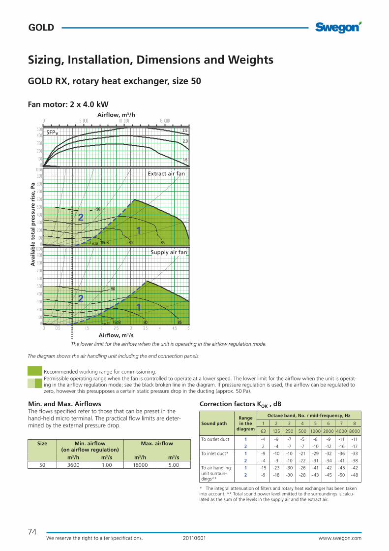
Min. and Max. AirflowsThe flows specified refer to those that can be preset in the hand-held micro terminal. The practical flow limits are deter-mined by the external pressure drop.
* The integral attenuation of filters and rotary heat exchanger has been taken into account. ** Total sound power level emitted to the surroundings is calcu-lated as the sum of the levels in the supply air and the extract air.
Correction factors KOK , dB
GOLD RX, rotary heat exchanger, size 50
Sizing, Installation, Dimensions and Weights
Range in the
diagram
Octave band, No. / mid-frequency, Hz
Sound path 1 2 3 4 5 6 7 8
63 125 250 500 1000 2000 4000 8000
To outlet duct 1 -4 -9 -7 -5 -8 -9 -11 -11
2 2 -4 -7 -7 -10 -12 -16 -17
To inlet duct* 1 -9 -10 -10 -21 -29 -32 -36 -33
2 -4 -3 -10 -22 -31 -34 -41 -38
To air handling unit surroun-dings**
1 -15 -23 -30 -26 -41 -42 -45 -42
2 -9 -18 -30 -28 -43 -45 -50 -48
Fan motor: 2 x 4.0 kW
2.5
2.0
1.5
75dB 80 85Lw,tot
90
75dB 80 85Lw,tot
90
12
12
Supply air fan
Extract air fan
SFPv
Airflow, m3/s
Ava
ilab
le t
ota
l pre
ssu
re r
ise,
Pa
Airflow, m3/h
Recommended working range for commissioning.Permissible operating range when the fan is controlled to operate at a lower speed. The lower limit for the airflow when the unit is operat-ing in the airflow regulation mode; see the black broken line in the diagram. If pressure regulation is used, the airflow can be regulated to zero, however this presupposes a certain static pressure drop in the ducting (approx. 50 Pa).
The lower limit for the airflow when the unit is operating in the airflow regulation mode.
Size Min. airflow (on airflow regulation)
Max. airflow
m3/h m3/s m3/h m3/s50 3600 1.00 18000 5.00
The diagram shows the air handling unit including the end connection panels.

75
GOLD
GO
LD
www.swegon.comWe reserve the right to alter specifications. 20110601
767628
3428*
Delivery and Transport within the SiteThe GOLD RX 50 is always supplied as one unit.
The air handling unit can be split into three sections to facilitate transporting it within the building site.
The three sections are joined together by bolts and the electri-cal and control cables have quick connectors.
The unit is supplied on 100 mm high support feet made of steel.
Duct connection optionsA: Specify right-hand or left-hand version when ordering!
B: The arrangement of the functional sections can be vertically reversed. Specify this by selecting fan arrangement 1 or 2 when placing orders!
C: Specify upper fan outlet for upward air discharge when ordering. (not for units installed outdoors)
Upward Upward
ForwardForward
Upward Upward
ForwardForward
Right-hand version
Left-hand version
Fan arrangement 1 Fan arrangement 2
Fan arrangement 1 Fan arrangement 2
Outside air Supply air Extract air Exhaust air
The unit can be divided into three sections at the building site.Dimensions: See A and D in the table above.Weight: A = 542 kg, D = 414 kg.
Clear Space for InspectionA clear space of 1,100 mm should be provided in front of the unit.
Power connection3-phase, 5-wire, 400 V -10/+15%, 50 Hz, 25 A
Rated data per fanMotor shaft power: 2 x 4.0 kW (2 x 2.4 kW)* motor control system, 3 x 400 V, 50 Hz *The motor control system limits the power of the take-off to the value
specified.
Power connection
Supplied on 100 mm high support feet. They can be removed or kept as they are when the unit is in place. The unit has provision for fitting the adjustable support feet.
Size A B D E F G H I J K L Weight, kg
50 1050 2318 570 150 800 1600 2253 423 115 360 2670 1498
GOLD RX, rotary heat exchanger, size 50
Sizing, Installation, Dimensions and Weights
A AD
* The air handling unit is supplied without end connection panel if a duct accessory housed in an insulated casing will be connected.
Division into sections for transport

76
GOLD
www.swegon.comWe reserve the right to alter specifications. 20110601
Min. and Max. AirflowsThe flows specified refer to those that can be preset in the hand-held micro terminal. The practical flow limits are deter-mined by the external pressure drop.
Correction factors KOK , dB
GOLD RX, rotary heat exchanger, size 60
Sizing, Installation, Dimensions and Weights
2.5
2.01.5
1
2
12
75dB 80 9085Lw,tot
75dB 80 9085Lw,tot
Supply air fan
Extract air fan
SFPv
Airflow, m3/s
Ava
ilab
le t
ota
l pre
ssu
re r
ise,
Pa
Airflow, m3/h
Recommended working range for commissioning.Permissible operating range when the fan is controlled to operate at a lower speed. The lower limit for the airflow when the unit is operat-ing in the airflow regulation mode; see the black broken line in the diagram. If pressure regulation is used, the airflow can be regulated to zero, however this presupposes a certain static pressure drop in the ducting (approx. 50 Pa).
The lower limit for the airflow when the unit is operating in the airflow regulation mode.
Size Min. airflow (on airflow regulation)
Max. airflow
m3/h m3/s m3/h m3/s60 3600 1.00 23400 6.50
* The integral attenuation of filters and rotary heat exchanger has been taken into account. ** Total sound power level emitted to the surroundings is calcu-lated as the sum of the levels in the supply air and the extract air.
Range in the
diagram
Octave band, No. / mid-frequency, Hz
Sound path 1 2 3 4 5 6 7 8
63 125 250 500 1000 2000 4000 8000
To outlet duct 1 -4 -9 -7 -5 -8 -9 -11 -11
2 2 -4 -7 -7 -10 -12 -16 -17
To inlet duct* 1 -9 -10 -10 -21 -29 -32 -36 -33
2 -4 -3 -10 -22 -31 -34 -41 -38
To air handling unit surroun-dings**
1 -15 -23 -30 -26 -41 -42 -45 -42
2 -9 -18 -30 -28 -43 -45 -50 -48
Fan motor: 2 x 4.0 kW, capacity variant 1 Fan motor: 2 x 6.5 kW, capacity variant 2
2.5
2.01.5
75dB 80 90
95
85Lw,tot
75dB 80 90
95
85Lw,tot
1
2
12
Supply air fan
Extract air fan
SFPv
Airflow, m3/s
Ava
ilab
le t
ota
l pre
ssu
re r
ise,
Pa
Airflow, m3/h
The diagram shows the air handling unit including the end connection panels.
77
GOLD
GO
LD
www.swegon.comWe reserve the right to alter specifications. 20110601
GOLD RX, rotary heat exchanger, size 60
Sizing, Installation, Dimensions and Weights
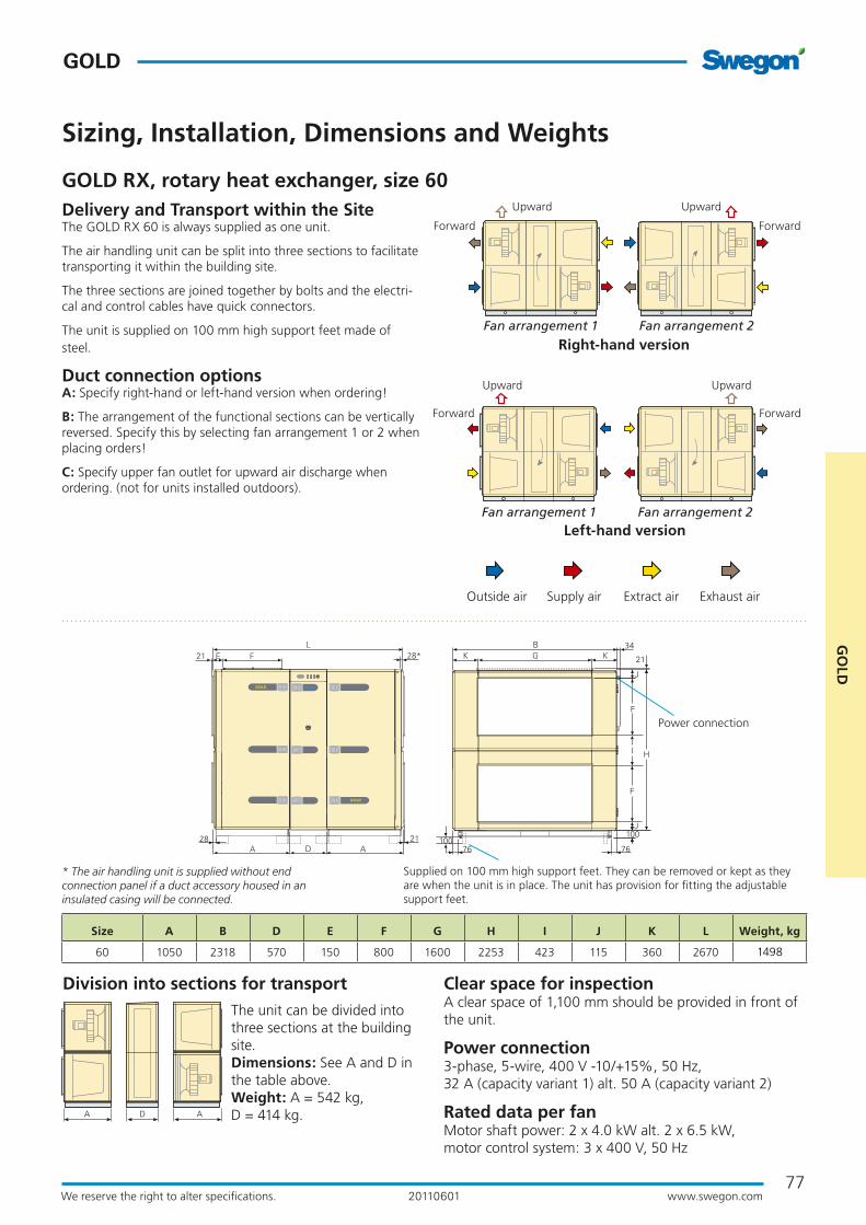
Delivery and Transport within the SiteThe GOLD RX 60 is always supplied as one unit.
The air handling unit can be split into three sections to facilitate transporting it within the building site.
The three sections are joined together by bolts and the electri-cal and control cables have quick connectors.
The unit is supplied on 100 mm high support feet made of steel.
Duct connection optionsA: Specify right-hand or left-hand version when ordering!
B: The arrangement of the functional sections can be vertically reversed. Specify this by selecting fan arrangement 1 or 2 when placing orders!
C: Specify upper fan outlet for upward air discharge when ordering. (not for units installed outdoors).
The unit can be divided into three sections at the building site.Dimensions: See A and D in the table above.Weight: A = 542 kg, D = 414 kg.
Size A B D E F G H I J K L Weight, kg
60 1050 2318 570 150 800 1600 2253 423 115 360 2670 1498
A AD
767628
3428*
Power connection
Supplied on 100 mm high support feet. They can be removed or kept as they are when the unit is in place. The unit has provision for fitting the adjustable support feet.
* The air handling unit is supplied without end connection panel if a duct accessory housed in an insulated casing will be connected.
Upward Upward
ForwardForward
Upward Upward
ForwardForward
Right-hand version
Left-hand version
Fan arrangement 1 Fan arrangement 2
Fan arrangement 1 Fan arrangement 2
Outside air Supply air Extract air Exhaust air
Division into sections for transport Clear space for inspectionA clear space of 1,100 mm should be provided in front of the unit.
Power connection3-phase, 5-wire, 400 V -10/+15%, 50 Hz, 32 A (capacity variant 1) alt. 50 A (capacity variant 2)
Rated data per fanMotor shaft power: 2 x 4.0 kW alt. 2 x 6.5 kW, motor control system: 3 x 400 V, 50 Hz

78
GOLD
www.swegon.comWe reserve the right to alter specifications. 20110601
Min. and Max. AirflowsThe flows specified refer to those that can be preset in the hand-held micro terminal. The practical flow limits are deter-mined by the external pressure drop.
Correction factors KOK , dB
GOLD RX, rotary heat exchanger, size 70
Sizing, Installation, Dimensions and Weights
Fan motor: 2 x 6.5 kW
2.5
2.0
1.5
75dB 80 85
80 85 90
12
12 90
Lw,tot
75dBLw,tot
Supply air fan
Extract air fan
SFPv
Airflow, m3/s
Ava
ilab
le t
ota
l pre
ssu
re r
ise,
Pa
Airflow, m3/h
Recommended working range for commissioning.Permissible operating range when the fan is controlled to operate at a lower speed. The lower limit for the airflow when the unit is operat-ing in the airflow regulation mode; see the black broken line in the diagram. If pressure regulation is used, the airflow can be regulated to zero, however this presupposes a certain static pressure drop in the ducting (approx. 50 Pa).
The lower limit for the airflow when the unit is operating in the airflow regulation mode.
Size Min. airflow (on airflow regulation)
Max. airflow
m3/h m3/s m3/h m3/s70 5400 1.50 27000 7.50
* The integral attenuation of filters and rotary heat exchanger has been taken into account. ** Total sound power level emitted to the surroundings is calcu-lated as the sum of the levels in the supply air and the extract air.
Range in the
diagram
Octave band, No. / mid-frequency, Hz
Sound path 1 2 3 4 5 6 7 8
63 125 250 500 1000 2000 4000 8000
To outlet duct 1 -4 -9 -7 -5 -8 -9 -11 -11
2 2 -4 -7 -7 -10 -12 -16 -17
To inlet duct* 1 -9 -10 -10 -21 -29 -32 -36 -33
2 -4 -3 -10 -22 -31 -34 -41 -38
To air handling unit surroun-dings**
1 -15 -23 -30 -26 -41 -42 -45 -42
2 -9 -18 -30 -28 -43 -45 -50 -48
The diagram shows the air handling unit including the end connection panels.

79
GOLD
GO
LD
www.swegon.comWe reserve the right to alter specifications. 20110601
767652
52*
GOLD RX, rotary heat exchanger, size 70
Sizing, Installation, Dimensions and Weights
Delivery and Transport within the SiteThe GOLD RX 70 is supplied as two units. The one unit consists of the centre section with heat exchanger and the fan/filter section where the fan is mounted in the upper level. The other unit consists of a fan/filter section in which the fan is placed in the lower level.
The air handling unit can be split into three sections to facilitate transporting it within the building site.
The three sections are joined together by bolts and the electri-cal and control cables have quick connectors.
The unit is supplied on 100 mm high support feet made of steel.
Duct connection optionsA: Specify right-hand or left-hand version when ordering!
B: The arrangement of the functional sections can be vertically reversed. Specify this by selecting fan arrangement 1 or 2 when placing orders!
C: Specify upper fan outlet for upward air discharge when ordering. (not for units installed outdoors)
The unit can be divided into three sections at the building site.Dimensions: See A and D in the table above.Weight: A = 866 kg, D = 579 kg.
Clear Space for InspectionA clear space of 1,100 mm should be provided in front of the unit.
Power connection3-phase, 5-wire, 400 V -10/+15%, 50 Hz, 32 A
Rated data per fanMotor shaft power: 2 x 6.5 kW (2 x 3.9 kW)* motor control system, 3 x 400 V, 50 Hz *The motor control system limits the power of the take-off to the value
specified.
Power connection
Supplied on 100 mm high support feet. They can be removed or kept as they are when the unit is in place. The unit has provision for fitting the adjustable support feet.
Size A B D E F G H I J K L Weight, kg
70 1275 2637 570 164 1000 1800 2640 319 161 419 3120 2311
A AD
* The air handling unit is supplied without end connection panel if a duct accessory housed in an insulated casing will be connected.
Upward Upward
ForwardForward
Upward Upward
ForwardForward
Right-hand version
Left-hand version
Fan arrangement 1 Fan arrangement 2
Fan arrangement 1 Fan arrangement 2
Outside air Supply air Extract air Exhaust air
Division into sections for transport

80
GOLD
www.swegon.comWe reserve the right to alter specifications. 20110601
Min. and Max. AirflowsThe flows specified refer to those that can be preset in the hand-held micro terminal. The practical flow limits are deter-mined by the external pressure drop.
Correction factors KOK , dB
GOLD RX, rotary heat exchanger, size 80
Sizing, Installation, Dimensions and Weights
80 85 90
80 85 90
2.52.01.5
90
75dBLw,tot
75dBLw,tot
12
12
Supply air fan
Extract air fan
SFPv
Airflow, m3/s
Ava
ilab
le t
ota
l pre
ssu
re r
ise,
Pa
Airflow, m3/h
Recommended working range for commissioning.Permissible operating range when the fan is controlled to operate at a lower speed. The lower limit for the airflow when the unit is operat-ing in the airflow regulation mode; see the black broken line in the diagram. If pressure regulation is used, the airflow can be regulated to zero, however this presupposes a certain static pressure drop in the ducting (approx. 50 Pa).
The lower limit for the airflow when the unit is operating in the airflow regulation mode.
Size Min. airflow (on airflow regulation)
Max. airflow
m3/h m3/s m3/h m3/s80 5400 1.50 34200 9.50
* The integral attenuation of filters and rotary heat exchanger has been taken into account. ** Total sound power level emitted to the surroundings is calcu-lated as the sum of the levels in the supply air and the extract air.
Range in the
diagram
Octave band, No. / mid-frequency, Hz
Sound path 1 2 3 4 5 6 7 8
63 125 250 500 1000 2000 4000 8000
To outlet duct 1 -4 -9 -7 -5 -8 -9 -11 -11
2 2 -4 -7 -7 -10 -12 -16 -17
To inlet duct* 1 -9 -10 -10 -21 -29 -32 -36 -33
2 -4 -3 -10 -22 -31 -34 -41 -38
To air handling unit surroun-dings**
1 -15 -23 -30 -26 -41 -42 -45 -42
2 -9 -18 -30 -28 -43 -45 -50 -48
The diagram shows the air handling unit including the end connection panels.
Fan motor: 2 x 6.5 kW, capacity variant 1 Fan motor: 2 x 10 kW, capacity variant 2
80 85 90 95
2.52.01.5
80 85 90
12
12
75dBLw,tot
75dBLw,tot
SFPv
Airflow, m3/s
Ava
ilab
le t
ota
l pre
ssu
re r
ise,
Pa
Airflow, m3/h
Supply air fan
Extract air fan

81
GOLD
GO
LD
www.swegon.comWe reserve the right to alter specifications. 20110601
A AD
767652
52* 137
GOLD RX, rotary heat exchanger, size 80
Sizing, Installation, Dimensions and Weights
Delivery and Transport within the SiteThe GOLD RX 80 is supplied as two units. The one unit consists of the centre section with heat exchanger and the fan/filter section where the fan is mounted in the upper level. The other unit consists of a fan/filter section in which the fan is placed in the lower level.
The air handling unit can be split into three sections to facilitate transporting it within the building site.
The three sections are joined together by bolts and the electri-cal and control cables have quick connectors.
The unit is supplied on 100 mm high support feet made of steel.
Duct connection optionsA: Specify right-hand or left-hand version when ordering!
B: The arrangement of the functional sections can be vertically reversed. Specify this by selecting fan arrangement 1 or 2 when placing orders!
C: Specify upper fan outlet for upward air discharge when ordering. (not for units installed outdoors)
The unit can be divided into three sections at the building site.Dimensions: See A and D in the table above.Weight: A = 866 kg, D = 579 kg.
Clear Space for InspectionA clear space of 1,100 mm should be provided in front of the unit.
Power connection3-phase, 5-wire, 400 V -10/+15%, 50 Hz, 50 A (capacity variant 1) alt. 80 A (capacity variant 2)
Rated data per fanMotor shaft power: 2 x 6.5 kW alt. 2 x 10 kW, motor control system: 3 x 400 V, 50 Hz
Size A B D E F G H I J K L Weight, kg
80 1275 2637 570 164 1000 1800 2640 319 161 419 3120 2311
Supplied on 100 mm high support feet. They can be removed or kept as they are when the unit is in place. The unit has provision for fitting the adjustable support feet.
* The air handling unit is supplied without end connection panel if a duct accessory housed in an insulated casing will be connected.
Upward Upward
ForwardForward
Upward Upward
ForwardForward
Right-hand version
Left-hand version
Fan arrangement 1 Fan arrangement 2
Fan arrangement 1 Fan arrangement 2
Outside air Supply air Extract air Exhaust air
Division into sections for transport
Power connection Applies to capacity variant 2 only
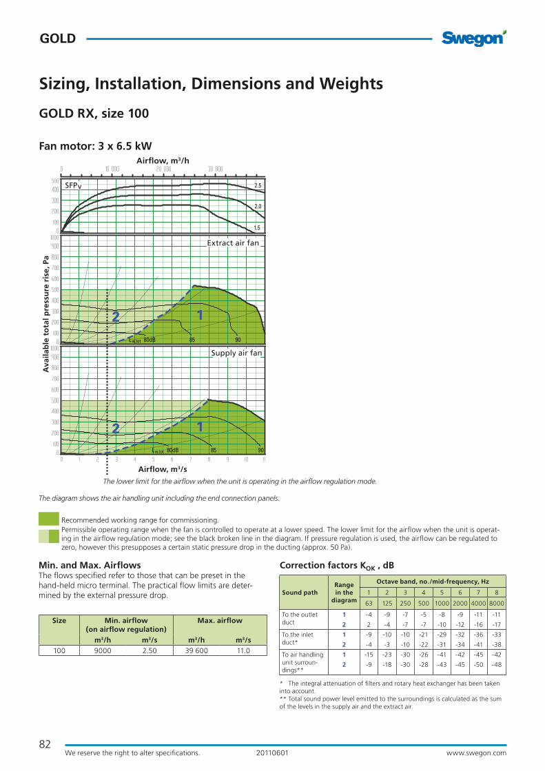
82
GOLD
www.swegon.comWe reserve the right to alter specifications. 20110601
GOLD RX, size 100
Sizing, Installation, Dimensions and Weights
Min. and Max. AirflowsThe flows specified refer to those that can be preset in the hand-held micro terminal. The practical flow limits are deter-mined by the external pressure drop.
Size Min. airflow (on airflow regulation)
Max. airflow
m3/h m3/s m3/h m3/s100 9000 2.50 39 600 11.0
Correction factors KOK , dB
Fan motor: 3 x 6.5 kW
80dB 85 90Lw,tot
80dB 85 90Lw,tot
2.5
2.0
1.5
12
12
Supply air fan
Extract air fan
SFPv
Airflow, m3/s
Ava
ilab
le t
ota
l pre
ssu
re r
ise,
Pa
Airflow, m3/h
The lower limit for the airflow when the unit is operating in the airflow regulation mode.
* The integral attenuation of filters and rotary heat exchanger has been taken into account.** Total sound power level emitted to the surroundings is calculated as the sum of the levels in the supply air and the extract air.
Range in the
diagram
Octave band, no./mid-frequency, Hz
Sound path 1 2 3 4 5 6 7 8
63 125 250 500 1000 2000 4000 8000
To the outletduct
1 -4 -9 -7 -5 -8 -9 -11 -11
2 2 -4 -7 -7 -10 -12 -16 -17
To the inletduct*
1 -9 -10 -10 -21 -29 -32 -36 -33
2 -4 -3 -10 -22 -31 -34 -41 -38
To air handling unit surroun-dings**
1 -15 -23 -30 -26 -41 -42 -45 -42
2 -9 -18 -30 -28 -43 -45 -50 -48
The diagram shows the air handling unit including the end connection panels.
Recommended working range for commissioning.Permissible operating range when the fan is controlled to operate at a lower speed. The lower limit for the airflow when the unit is operat-ing in the airflow regulation mode; see the black broken line in the diagram. If pressure regulation is used, the airflow can be regulated to zero, however this presupposes a certain static pressure drop in the ducting (approx. 50 Pa).

83
GOLD
GO
LD
www.swegon.comWe reserve the right to alter specifications. 20110601
56* N O
56
MN
P
P
77 3186 77
1048 1000 10481048122
45
137
Sizing, Installation, Dimensions and Weights
GOLD RX, size 100
Delivery and Transport within the SiteThe GOLD RX 100 is supplied in five separate sections: two fan sections, two filter sections and one heat exchanger section. The heat exchanger section can also be supplied split into two cas-ing sections and rotor, in which case the rotor is supplied tilted in a transport cradle (transport height = 2,930 mm, minimum transport width = 2,350 mm). After the heat exchanger has been assembled, if required, the five sections are installed at the building site.
The five sections are joined together by bolts and the electrical and control cabling between the parts have quick-fit connec-tors.
Duct connection optionsA: Specify right-hand or left-hand version when ordering!
B: The arrangement of the functional sections can be vertically reversed. Specify this by selecting fan arrangement 1 or 2 when placing orders.
C: Specify upper fan outlet for upward air discharge when or-dering. (not for units installed outdoors) N.B.! Duct connection size: 2500 x 800 mm.
filter and fan sections See dimensions A and P in the table above. Weight: fan section = 875 kg, filter section = 529 kg.
Heat exchanger section, mountedSee dimensions D and H in the table above. Weight: heat exchanger section = 1,174 kg.
Heat exchanger section, two casing sections + rotorSee transport dimensions in the Delivery and at-site trans-port section above. Weight: casing lower section = 494 kg, casing upper sec-tion = 270 kg, rotor = 410 kg, transport cradle = 190 kg
Clear space for inspectionA clear space of 1,000 mm should be provided in front of the unit.
Power connection3-phase, 5-wire, 400 V -10/+15%, 50 Hz, 50 A
Rated data per fanMotor shaft power: 3 x 6.5 kW (3 x 3.9 kW)*, motor control system, 3 x 400 V, 50 Hz *The motor control system limits the power of the take-off to the value specified.
Transport at building site, dim. and weights
Size A B D E F G H I J K L M N O P Weight, kg
100 1126 3340 1070 191 1200 2400 3440 520 210 470 3322 800 170 2500 1720 3982
Power connection
* The air handling unit is supplied without end connection panel if a duct accessory housed in an insulated casing will be con-nected.
Upward Upward
ForwardForward
Upward Upward
ForwardForward
Right-hand version
Left-hand version
Fan arrangement 1 Fan arrangement 2
Fan arrangement 1 Fan arrangement 2
Outdoor air Supply air Extract air Exhaust air

84
GOLD
www.swegon.comWe reserve the right to alter specifications. 20110601
GOLD RX, size 120
Sizing, Installation, Dimensions and Weights
Min. and Max. AirflowsThe flows specified refer to those that can be preset in the hand-held micro terminal. The practical flow limits are deter-mined by the external pressure drop.
Size Min. airflow (on airflow regulation)
Max. airflow
m3/h m3/s m3/h m3/s120 9000 2.50 50 400 14.0
Correction factors KOK , dB
80dB 85 90 95Lw,tot
80dB 85 90 95Lw,tot
2.5
2.01.5
12
12
Supply air fan
Extract air fan
SFPv
Airflow, m3/s
Ava
ilab
le t
ota
l pre
ssu
re r
ise,
Pa
Airflow, m3/h
* The integral attenuation of filters and rotary heat exchanger has been taken into account.** Total sound power level emitted to the surroundings is calculated as the sum of the levels in the supply air and the extract air.
Range in the
diagram
Octave band, no./mid-frequency, Hz
Sound path 1 2 3 4 5 6 7 8
63 125 250 500 1000 2000 4000 8000
To the outletduct
1 -4 -9 -7 -5 -8 -9 -11 -11
2 2 -4 -7 -7 -10 -12 -16 -17
To inlet duct* 1 -9 -10 -10 -21 -29 -32 -36 -33
2 -4 -3 -10 -22 -31 -34 -41 -38
To air handling unit surroun-dings**
1 -15 -23 -30 -26 -41 -42 -45 -42
2 -9 -18 -30 -28 -43 -45 -50 -48
Recommended working range for commissioning.Permissible operating range when the fan is controlled to operate at a lower speed. The lower limit for the airflow when the unit is operat-ing in the airflow regulation mode; see the black broken line in the diagram. If pressure regulation is used, the airflow can be regulated to zero, however this presupposes a certain static pressure drop in the ducting (approx. 50 Pa).
The lower limit for the airflow when the unit is operating in the airflow regulation mode.
The diagram shows the air handling unit including the end connection panels.
Fan motor: 3 x 6.5 kW, capacity variant 1 Fan motor: 3 x 10 kW, capacity variant 2
80dB 85 90 95
80dB 85 90 95Lw,tot
2.5
2.01.5
12
12
Lw,tot
SFPv
Airflow, m3/s
Ava
ilab
le t
ota
l pre
ssu
re r
ise,
Pa
Airflow, m3/h
Supply air fan
Extract air fan

85
GOLD
GO
LD
www.swegon.comWe reserve the right to alter specifications. 20110601
Sizing, Installation, Dimensions and Weights
GOLD RX, size 120
56* N O
56
MN
P
P
77 3186 77
1048 1000 10481048122
45
137
Delivery and Transport within the SiteThe GOLD RX 120 is supplied in five separate sections: two fan sections, two filter sections and one heat exchanger section. The heat exchanger section can also be supplied split into two cas-ing sections and rotor, in which case the rotor is supplied tilted in a transport cradle (transport height = 2,930 mm, minimum transport width = 2,350 mm). After the heat exchanger has been assembled, if required, the five sections are installed at the building site.
The five sections are joined together by bolts and the electrical and control cabling between the parts have quick-fit connec-tors.
Duct connection optionsA: Specify right-hand or left-hand version when ordering!
B: The arrangement of the functional sections can be vertically reversed. Specify this by selecting fan arrangement 1 or 2 when placing orders.
C: Specify upper fan outlet for upward air discharge when or-dering. (not for units installed outdoors) N.B.! Duct connection size: 2500 x 800 mm.
Clear space for inspectionA clear space of 1,000 mm should be provided in front of the unit.
Power connection3-phase, 5-wire, 400 V -10/+15%, 50 Hz, 80 A (capacity variant 1) alt. 125 A (capacity variant 2)
Rated data per fanMotor shaft power: 3 x 6.5 kW alt. 3 x 10 kW, motor control system: 3 x 400 V, 50 Hz
Transport at building site, dim. and weights
Size A B D E F G H I J K L M N O P Weight, kg
120 1126 3340 1070 191 1200 2400 3440 520 210 470 3322 800 170 2500 1720 3982
Power connection
* The air handling unit is supplied without end connection panel if a duct accessory housed in an insulated casing will be con-nected.
Upward Upward
ForwardForward
Upward Upward
ForwardForward
Right-hand version
Left-hand version
Fan arrangement 1 Fan arrangement 2
Fan arrangement 1 Fan arrangement 2
Outdoor air Supply air Extract air Exhaust air
filter and fan sections See dimensions A and P in the table above. Weight: fan section = 875 kg, filter section = 529 kg.
Heat exchanger section, mountedSee dimensions D and H in the table above. Weight: heat exchanger section = 1,174 kg.
Heat exchanger section, two casing sections + rotorSee transport dimensions in the Delivery and at-site trans-port section above. Weight: casing lower section = 494 kg, casing upper sec-tion = 270 kg, rotor = 410 kg, transport cradle = 190 kg