sizing, selection, and installation of refineries rp*5z0 pt*ii 911 1 0732290 05111112 75b sizing,...
TRANSCRIPT

~ ~ ~ . l n t e r n a t i o n a l - S t ~ ~ d ~ ~ d . ~ ~ ~ - p - p p ~
p~
API RP*5Z0 P T * I I 911 1 0732290 05111112 75b
Sizing, Selection, and Installation Of Pressure-Relieving Devices in Refineries
Part II-Installation
API RECOMMENDED PRACTICE 520 FOURTH EDITION, DECEMBER 1994
American Petroleum Institute 1 220 L Street, Northwest Washington, D.C. 20005
11'
Copyright by the American Petroleum Institute Thu May 11 15:57:11 2006

www.lnternational-Standard.com - p~ - -
A P I RP*520 PT*II 94 0732290 0541133 692 W
Sizing, Selection, and Installation Of Pressure-Relieving Devices in Refineries
Part Il-Installation
Manufacturing, Distribution and Marketing Department
API RECOMMENDED PRACTICE 520 FOURTH EDITION, DECEMBER 1994
American Petroleum Institute
Copyright by the American Petroleum Institute Thu May 11 15:57:24 2006
- -
A P I RP*520 PT*II 94 0732290 0541114 529
SPECIAL NOTES
1. API PUBLICATIONS NECESSARILY ADDRESS PROBLEMS OF A GENERAL NATURE. WITH RESPECT TO PARTICULAR CIRCUMSTANCES, LOCAL, STATE, AND FEDERAL LAWS AND REGULATIONS SHOULD BE REVIEWED.
2. API IS NOT UNDERTAKING TO MEET THE DUTIES OF EMPLOYERS, MANU- FACTURERS, OR SUPPLIERS TO WARN AND PROPERLY TRAIN AND EQUIP THEIR EMPLOYEES, AND OTHERS EXPOSED, CONCERNING HEALTH AND SAFETY RISKS AND PRECAUTIONS, NOR UNDERTAKING THEIR OBLIGATIONS UNDER LOCAL, STATE, OR FEDERAL LAWS.
3. INFORMATION CONCERNING SAFETY AND HEALTH RISKS AND PROPER PRECAUTIONS WITH RESPECT TO PARTICULAR MATERIALS AND CONDI- TIONS SHOULD BE OBTAINED FROM THE EMPLOYER, THE MANUFACTURER OR SUPPLIER OF THAT MATERIAL, OR THE MATERIAL SAFETY DATA SHEET.
4. NOTHING CONTAINED IN ANY API PUBLICATION IS TO BE CONSTRUED AS GRANTING ANY RIGHT, BY IMPLICATION OR OTHERWISE, FOR THE MANU- FACTURE, SALE, OR USE OF ANY METHOD, APPARATUS, OR PRODUCT COV- ERED BY LETTERS PATENT. NEITHER SHOULD ANYTHING CONTAINED IN THE PUBLICATION BE CONSTRUED AS INSURING ANYONE AGAINST LIABIL- ITY FOR INFRINGEMENT OF LETTERS PATENT.
5. GENERALLY, API STANDARDS ARE REVIEWED AND REVISED, REAF- FIRMED, OR WITHDRAWN AT LEAST EVERY FIVE YEARS. SOMETIMES A ONE- TIME EXTENSION OF UP TO TWO YEARS WILL BE ADDED TO THIS REVIEW CYCLE. THIS PUBLICATION WILL NO LONGER BE IN EFFECT FIVE YEARS AF- TER ITS PUBLICATION DATE AS AN OPERATIVE API STANDARD OR, WHERE AN EXTENSION HAS BEEN GRANTED, UPON REPUBLICATION. STATUS OF THE PUBLICATION CAN BE ASCERTAINED FROM THE API AUTHORING DEPART- MENT [TELEPHONE (202) 682-8000]. A CATALOG OF API PUBLICATIONS AND MATERIALS IS PUBLISHED ANNUALLY AND UPDATED QUARTERLY BY API, 1220 L STREET, N.W., WASHINGTON, D.C. 20005.
Copyright O 1994 American Petroleum Institute
Copyright by the American Petroleum Institute Thu May 11 15:57:24 2006

API RP*520 PT*II 94 D 0732290 054LLL5 4b5
FOREWORD
This recommended practice is intended to cover methods of installation for pressure relief devices for equipment that has a maximum allowable working pressure of 15 pounds per square inch gauge (1.03 bar g) or greater.
API publications may be used by anyone desiring to do so. Every effort has been made by the Institute to assure the accuracy and reliability of the data contained in them; however, the Institute makes no representation, warranty, or guarantee in connection with this pub- lication and hereby expressly disclaims any liability or responsibility for loss or damage re- sulting from its use or for the violation of any federal, state, or municipal regulation with which this publication may conflict.
Suggested revisions are invited and should be submitted to the director of the Manufac- turing, Distribution and Marketing Department, American Petroleum Institute, 1220 L Street, N.W., Washington, D.C. 20005.
iii
Copyright by the American Petroleum Institute Thu May 11 15:57:24 2006


www.lnternational-Standard.com
API RPw.520 PT*II 94 0732290 054LL17 238 =
Page
. . . . . . . . . . . . . . . . . . . . . . . . . . . . . . . . . . . . . . . . SECTION 6-DRAIN PIPING 15 . . . . . . . . . . . . . . . . . . . . . . . . . . 6.1 Installation Conditions that Require Drain Piping 15
. . . . . . . . . . . . . . . . . . . . . . . . . . . . . . 6.2 Safe Practice for Installation of Drain Piping 15
SECTION 7-PRESSURE RELIEF DEVICE LOCATION AND . . . . . . . . . . . . . . . . . . . . . . . . . . . . . . . . . . . . . . . . . . . . . . POSITION 15
7.1 Inspection and Maintenance . . . . . . . . . . . . . . . . . . . . . . . . . . . . . . . . . . . . . . . . . . . . 15 7.2 Proximity to Pressure Source . . . . . . . . . . . . . . . . . . . . . . . . . . . . . . . . . . . . . . . . . . . 15 7.3 Proximity to Other Equipment . . . . . . . . . . . . . . . . . . . . . . . . . . . . . . . . . . . . . . . . . . 15
. . . . . . . . . . . . . . . . . . . . . . . . . . . . . . . . . . . . . . . . . . . . . . . . . 7.3.1 Reducing Stations 15 . . . . . . . . . . . . . . . . . . . . . . . . . . . . . . . . . . . . . 7.3.2 Orifice Plates and Flow Nozzles 15
. . . . . . . . . . . . . . . . . . . . . . . . . . . . . . . . . . . . . . . . . . . 7.3.3 Other Valves and Fittings 15 . . . . . . . . . . . . . . . . . . . . . . . . . . . . . . . . . . . . . . . . . . . . . . . . . . . . . 7.4 Mounting Position 15
. . . . . . . . . . . . . . . . . . . . . . . . . . . . . . . . . . . . . . . . . . . . . . . . . . 7.5 Test or Lifting Levers 16 7.6 Heat Tracing and Insulation . . . . . . . . . . . . . . . . . . . . . . . . . . . . . . . . . . . . . . . . . . . . 16
. . . . . . . . . . . . . . . . . . . . . . . . SECTION 8-BOLTING AND GASKETING 17 . . . . . . . . . . . . . . . . . . . . . . . . . . . . . . . . . . . . . . . . . . . . . . . . . . . . 8.1 Care in Installation 17
. . . . . . . . . . . . . . . . . . . . 8.2 Proper Gasketing and Bolting for Service Requirements 17
SECTION 9-MULTIPLE PRESSURE RELIEF VALVES WITH . . . . . . . . . . . . . . . . . . . . . . . . . . . . . STAGGERED SETTINGS 17
SECTION 10-PRE-INSTALLATION HANDLING AND . . . . . . . . . . . . . . . . . . . . . . . . . . . . . . . . . . . . . . . . . INSPECTION 17
10.1 Storage and Handling of Pressure Relief Devices . . . . . . . . . . . . . . . . . . . . . . . . 17 10.2 Inspection and Testing of Pressure Relizf Valves ......................... 17
. . . . . . . . . . . . . . . . . . . . . . . . . . . . . . . . . . . . 10.3 Inspection of Rupture Disk Devices 18 10.4 Inspection and Cleaning of Systems Before Installation ................... 18
Figures 1-Typical Pressure Relief Valve Installation: Atmospheric (Open)
Discharge ............................................................ 2 2-Typical Pressure Relief Valve Installation: Closed System Discharge ........ 3 3-Typical Pressure Relief Valve Mounted on Process Line ................... 4 4.. Typical Pressure Relief Valve Mounted on Long Inlet Pipe ................. 5 5-Typical Pilot-Operated Pressure Relief Valve Installation .................. 5 &Typical Pressure Relief Valve Installation with Vent Pipe .................. 6 7-Typical Rupture Disk Assembly Installed in Combination with a Pressure
. . . . . . . . . . . . . . . . . . . . . . . . . . . . . . . . . . . . . . . . . . . . . . . . . . . . . . . . . . Relief Valve 7 8-Installation Avoiding Process Laterals Connected to Pressure Relief
. . . . . . . . . . . . . . . . . . . . . . . . . . . . . . . . . . . . . . . . . . . . . . . . . . . . . Valve Inlet Piping 8 9-Typical Pressure Relief Valve Installation with an Isolation Valve ........... 10 10-Typical Pressure Relief Valve Installation Arrangement for 100 Percent
.............................................. Spare Relieving Capacity 11 11-Alternate Pressure Relief Valve Installation Arrangement for 100 Percent
. . . . . . . . . . . . . . . . . . . . . . . . . . . . . . . . . . . . . . . . . . . . . Spare Relieving Capacity 12 12-Typical Flare Header Block Valves .................................... 13 13-Typical Isolation Block Valves for Spare Compressor .................... 14 14-Typical Installation Avoiding Unstable Flow Patterns at Pressure Relief
. . . . . . . . . . . . . . . . . . . . . . . . . . . . . . . . . . . . . . . . . . . . . . . . . . . . . . . . . . Valve Inlet 16
Copyright by the American Petroleum Institute Thu May 11 15:57:24 2006
API RP*520 PT*II 94 0732290 05YLLLB 174
Sizing; Selection, and Installation of Pressure-Relieving Devices in Refineries
Part I I-Installation
SECTION 1-GENERAL
1.1 Scope 1.3 Referenced Publications This recommended practice is intended to cover methods of
installation for pressure relief devices for equipment that has a maximum allowable working pressure (MAWP) of 15 pounds per square inch gauge (psig) (1.03 bar g) or greater. Pressure relief valves or rupture disks may be used independently or in combination with each other to provide the required protection against excessive pressure accumulation. As used in this rec- ommended practice, the term pressure relief valve includes safety relief valves used in either compressible or incompress- ible fluid service. and relief valves used in incompressible fluid service. This recommended practice covers gas, vapor, steam, and incompressible fluid service; it does not cover special a p plications that require unusual installation considerations.
1.2 Definition of Terms The terminology for pressure relief devices that is used in
this recommended practice is in general agreement with the definitions given in ASME PTC 25.
The current editions of the following standards, codes, and specifications are cited in this recommended practice:
API
RP 521 Guide for Pressure-Relieving and Depressur- ing Systems
RP 576 Inspection of Pressure Relieving Devices
ASME'
PTC 25 Performance Test Code--Safety and Relief Valves
B3 1.3 Chemical Plant and Petroleum Refinery Piping
Boiler and Pressure Vessel Code, Section VIII, "Pressure Vessels"
SECTION 2-INLET PIPING TO PRESSURE RELIEF DEVICES
2.1 General Requirements the seat of a pressure relief valve, premature opening, or premature fatigue failure of certain valve parts, inlet and out-
For general requirements for piping, see Figures ' let piping, or both. Vibration in inlet piping to a rupture disk and 2. may adversely affect the burst pressure and life of the
rupture disk. 2.1.1 FLOW AND STRESS CONSIDERATIONS Detrimental effects of vibrations on the pressure relief de-
~~l~~ piping to the pressure relief device should provide vice can be reduced by minimizing the cause of vibrations,
for proper system performance. This requires design consid- by additional piping support, by use of either ~i lo t -o~era ted
eration of the flow-induced pressure drop in the inlet relief valves or soft-seated pressure relief valves, or by pro-
~~~~~~i~~ pressure losses in the system between the viding greater pressure differentials between the operating
protected vessel and a pressure relief device will adversely pressure and the set pressure.
affect the system-relieving capacity and can cause valve instability. In addition, the effect of stresses derived from both pressure relief device operation and externally applied
2.2 Pressure-Drop Limitations and I loads must be considered. For more complete piping design
Piping Configurations guidelines, see ASME B31.3.
2.1.2 VIBRATION CONSIDERATIONS
For pressure-drop limitations and piping configurations, see Figures 1 through 4.
Most vibrations that Occur in "let piping 'ystems are 'American Society of Mechanical Engineers, 345 East 47th Street, New random and complex. These vibrations may cause leakage at York, New York 10017.
Copyright by the American Petroleum Institute Thu May 11 15:57:25 2006

API RPs.520 PT*II 99 0732290 054LLL9 000.
API RECOMMENDED PRACTICE 520
2.2.1 PRESSURE LOSS AT THE PRESSURE a process line, the 3 percent limit should be applied to the RELIEF VALVE INLET sum of the loss in the normally non-flowing pressure relief
valve inlet pipe and the incremental pressure loss in the pro- Excessive pressure loss at the inlet of a pressure relief
cess line caused by the flow through the pressure relief valve can cause rapid opening and closing of the valve, or
valve. The pressure loss should be calculated using the rated chattering. Chattering will result in lowered capacity and
capacity of the pressure relief valve. Pressure losses can be damage to the seating surfaces. The pressure loss that affects reduced materially by rounding the entrance to the inlet pip- valve performance is caused by non-recoverable entrance
ing, by reducing the inlet line length, or by enIarging the in- losses (turbulent dissipation) and by friction within the inlet
let piping. Keeping the pressure loss below 3 percent piping to the pressure relief valve.
becomes progressively more difficult as the orifice size of a Chattering has sometimes occurred due to acceleration of pressure relief valve increases.
liquids in long inlet lines. The nominal size of the inlet piping must be the same as
2.2.2 SIZE AND LENGTH OF INLET PIPING TO or larger than the nominal size of the pressure relief valve in-
PRESSURE RELIEF VALVES let flange connection as shown in Figure 2. An engineering analysis of the valve performance at
When a pressure relief valve is installed on a line directly higher inlet losses may permit increasing the allowable pres- connected to a vessel, the total non-recoverable pressure loss sure loss above 3 percent. between the protected equipment and the pressure relief When a rupture disk device is used in combination with a valve should not exceed 3 percent of the set pressure of the pressure relief valve, the pressure-drop calculation must in- valve except as permitted in 2.2.3.1 for pilot-operated pres- clude the additional pressure drop developed by the disk sure relief valves. When a pressure relief valve is installed on (See 2.6 for additional information on rupture disk devices).
7 Weather cap
Pressure I \ I I relief valve I I
Long-radius elbow
Support to resist weight and reaction forces
Low-point drain - (See Note 2) 1 Nominal pipe diameter
Nonrecoverable losses not more than 3 percent of set pressure Vessel
Notes: 1. See Section 6. 2. Orient low-point drain-r weep hole-away from relief valve, structural steel, and operating area.
Figure I-Typical Pressure Relief Valve Installation: Atmospheric (Open) Discharge
Copyright by the American Petroleum Institute Thu May 11 15:57:25 2006

www.lnternational-Standard.com
API RP*520 PT*II 7Y 0732270 05YLL20 822 rn
2.2.3 REMOTE SENSING FOR PILOT-OPERATED may eliminate uncontrolled valve cycling or chattering for PRESSURE RELIEF VALVES a pop action pressure relief valve and will permit a mod-
ulating action pressure relief valve to achieve full lift at Remote sensing for pilot-operated pressure relief valves
the required overpressure. However, high inlet pressure can be utilized when there is excessive inlet pipe pressure
losses may induce pressure pulsations in the inlet piping loss or when the main valve must be located at a pressure
that can cause uncontrolled main valve cycling. Some source different from the pilot sensing point because of ser-
valves incorporate design features to prevent uncontrolled vice limitations of the main valve (see Figure 5).
cycling.
2.2.3.1 Inlet Pipe Loss Although remote sensing may eliminate valve chatter or permit a modulating valve to achieve full lift at the required
Remote sensing permits the pilot to sense the true sys- overpressure, the relieving capacity will be reduced by any tem pressure upstream of the piping loss. Remote sensing pressure drop in the inlet pipe.
To closed system (self-draining) 7
Bonnet vent piping for bellows type pressure relief valves, if required (See Note 1)
Nonrecoverable -1 I I
I I
pressure losses not more than 3 percent of set pressure
Nominal pipe diameter no less than valve inlet size
- - - - - - -
Note: 1. See Section 5.
r --I------ Flanged spool piece, if required to elevate PRV
-
--
Figure 2-Typical Pressure Relief Valve Installation: Closed System Discharge
Copyright by the American Petroleum Institute Thu May 11 15:57:25 2006

www.lnternational-Standard.com
API RPr520 P T * I I 94 0732290 0541121 769
4 API RECOMMENDED PRACTICE 520
2.2.3.2 Installation Guidelines normally no flow. Foreign matter may accumulate, or liquid may be trapped, creating interference with the valve's oper-
Remote sensing lines should measure static pressure ation or requiring more frequent valve maintenance. where the velocity is low. Otherwise, the pilot will sense an The inlet piping system to relief valves should be free- artificially low pressure due to the effect of velocity. draining from the pressure relief device to prevent accumu-
Ensure that the pilot sensing point is within the system lation of liquid or foreign matter in the piping. protected by the main valve.
For flowing pilots, remote sensing lines shall be sized to limit the pressure loss to 3 percent of the set pressure based 2.3 Inlet Stresses that Originate from on the maximum flow rate of the pilot at 110 percent of set Static Loads in the Discharge Piping pressure. Consult the manufacturer for recommendations.
For non-flowing pilots, remote sensing lines with a flow area of 0.070 square inches (45 square millimeters) is suffi- cient since no system medium flows through this type of pi- lot when the main valve is open and relieving.
Consider using pipe for remote sensing lines to ensure mechanical integrity.
If a block valve is installed in the remote sensing line, the guidelines in Section 4 should be followed. A closed block valve in a remote sense line renders the pressure relief valve inoperative.
2.2.4 CONFIGURATION OF INLET PIPING FOR PRESSURE RELIEF VALVES
Avoid the installation of a pressure relief valve at the end of a long horizontal inlet pipe through which there is
Improper design or construction of the discharge piping from a pressure relief device can set up stresses that will be transferred to the pressure relief device and its inlet piping. These stresses may cause a pressure relief valve to leak or malfunction or may change the burst pressure of a rupture disk. The pressure relief device manufacturer should be con- sulted about permissible loads and moments.
2.3.1 THERMAL STRESSES
Fluid flowing from the discharge of a pressure relief de- vice may cause a change in the temperature of the dis- charge piping. A change in temperature may also be caused by prolonged exposure to the sun or to heat radiated from nearby equipment. Any change in the temperature of the discharge piping will cause a change in the length of the
Vessel
Note: 1 . See 2.2.2 for pressure-loss limitation
Figure 3-Typical Pressure Relief Valve Mounted on Process Line
Copyright by the American Petroleum Institute Thu May 11 15:57:25 2006
www.lnternational-Standard.com
API RP*520 P T * I I 74 0732290 054LL22 bT5
piping and may cause stresses that will be transmitted to the pressure relief device and its inlet piping. The pressure relief device should be isolated from piping stresses through proper support, anchoring, or flexibility of the dis- charge piping.
2.3.2 MECHANICAL STRESSES
Discharge piping should be independently supported and carefully aligned. Discharge piping that is supported by only the pressure relief device will induce stresses in the pressure relief device and the inlet piping. Forced alignment of the discharge piping will also induce such stresses.
and also into the mounting nozzle and adjacent supporting vessel shell unless designed otherwise. The precise magni- tude of the loading and resulting stresses will depend on the reaction force and the configuration of the piping system. The designer is responsible for analyzing the discharge sys- tem to determine if the reaction forces and the associated bending moments will cause excessive stresses on any of the components in the system.
The magnitude of the reaction force will differ substan- tially depending on whether the installation is open or closed discharge. When an elbow is installed in the discharge sys- tem to direct the fluid up into a vent pipe, the location of the elbow and any supports is an important consideration in the analysis of the bending moments.
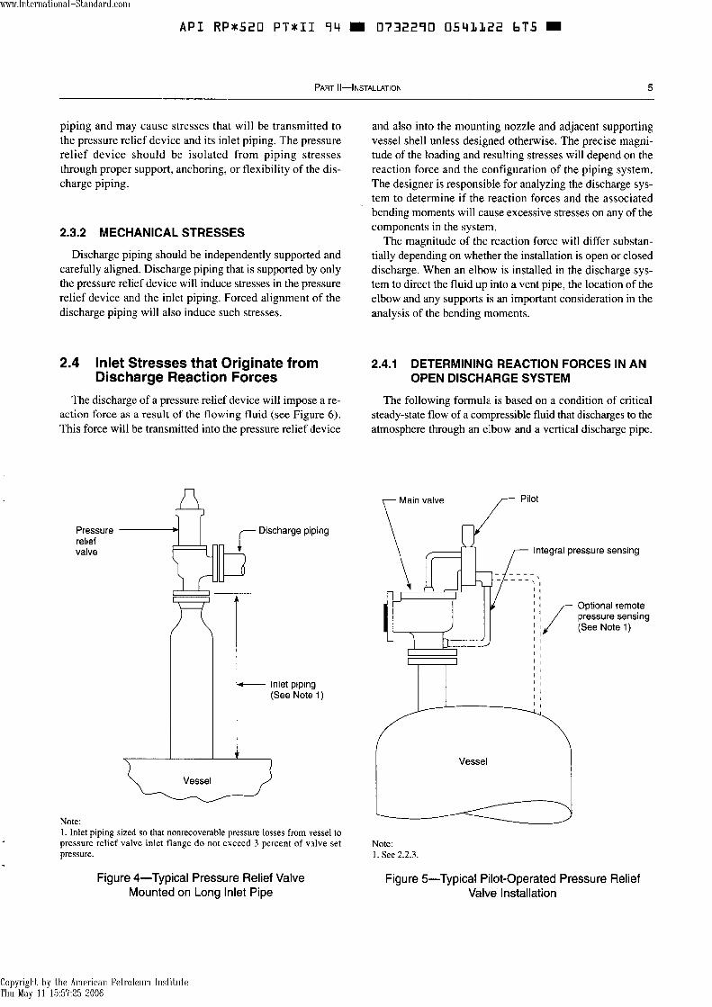
2.4 Inlet Stresses that Originate from 2.4.1 DETERMINING REACTION FORCES IN AN Discharge Reaction Forces OPEN DISCHARGE SYSTEM
The discharge of a pressure relief device will impose a re- The following formula is based on a condition of critical action force as a result of the flowing fluid (see Figure 6). steady-state flow of a compressible fluid that discharges to the This force will be transmitted into the pressure relief device atmosphere through an elbow and a vertical discharge pipe.
Pressure Discharge piping relief valve
&-
- Inlet piping (See Note 1)
v I
Vessel u Note: 1. Inlet piping sized so that nonrecoverable pressure losses from vessel to pressure relief valve inlet flange do not exceed 3 percent of valve set pressure.
Figure 4-Typical Pressure Relief Valve Mounted on Long lnlet Pipe
Integral pressure sensing
Optional remote pressure sensing (See Note 1 )
Vessel
Note: 1. See 2.2.3.
Figure 5-Typical Pilot-Operated Pressure Relief Valve Installation
Copyright by the American Petroleum Institute Thu May 11 15:57:25 2006

A P I R P * 5 2 0 P T * I I 94 0732290 05Y1123 5 3 1
6 API RECOMMENDED PRACTICE 520
The reaction force (F) includes the effects of both momentum In metric units,
Where:
F = reaction force at the point of discharge to the atmo- sphere, in pounds.
W = flow of any gas or vapor, in pounds per hour. k = ratio of specific heats (C,IC,).
C , = specific heat at constant pressure. C, = specific heat at constant volume. T = temperature at inlet, in degrees Rankine.
M = molecular weight of the process fluid. A = area of the outlet at the point of discharge, in square
inches. P = static pressure within the outlet at the point of dis-
charge, in pounds per square inch gauge.
F = reaction force at the point of discharge to the atmo- sphere, in newtons.
W = flow of any gas or vapor, in kilograms per second. k = ratio of specific heats (C,IC,).
C, = specific heat at constant pressure. C, = specific heat at constant volume. T = temperature at inlet, in degrees Kelvin.
M = molecular weight of the process fluid. A = area of the outlet at the point of discharge, in square
millimeters. P = static pressure within the outlet at the point of dis-
charge, in bars gauge.
2.4.2 DETERMINING REACTION FORCES IN A CLOSED DISCHARGE SYSTEM
Pressure relief devices that relieve under steady-state flow F (See Note 1) conditions into a closed system usually do not create large
forces and bending moments on the exhaust system. Only at A (See *) points of sudden expansion will there be any significant re-
action forces to be calculated. Closed discharge systems, however, do not lend themselves to simplified analytical techniques. A complex time history analysis of the piping
Vent pipe system may be required to obtain the true values of the reac- tion forces and associated moments.
Pressure 2.5 Isolation Valves in Inlet Piping relief valve Isolation valves located in the inlet piping to pressure re-
lief devices shall be in accordance with the guidelines in Section 4.
2.6 Rupture Disk Devices in Combination with Pressure Relief Valves
A rupture disk device may be used as the sole pressure re- lief device, or it may be installed between a pressure relief
Vessel
Notes: 1 . The support should be located as close as possible to the centerline of the vent pipe. 2. F = reaction force; A = cross-sectional area.
Figure &Typical Pressure Relief Valve Installation with Vent Pipe
valve and the vessel or on the downstream side of a pressure relief valve (see Figure 7).
For ASME Boiler and Pressure Vessel Code applications, the capacity of a pressure relief valve used in combination with a rupture disk mounted as shown in Figure 7 must be derated by 10 percent unless that particular combination has a capacity factor derived from testing as listed in the Na- tional Board of Boiler and Pressure Vessel Inspectors' pub- lication, Pressure Relief Device Certifications.
When a rupture disk device is used between the pressure relief valve and the protected vessel, a pressure indicator,
Copyright by the American Petroleum Institute Thu May 11 15:57:25 2006

www.lnternational-Standard.com
A P I R P * S 2 0 P T * I I 94 m 0732290 0541124 478 m
bleed valve, free vent, or suitable telltale indicator should be provided to permit detection of disk rupture or leakage. The user is cautioned that any pressure buildup between the rup- ture disk and the pressure relief valve will increase the vessel pressure at which the rupture disk will burst.
Only non-fragmenting rupture disk devices may be used beneath a pressure relief valve.
Rupture disks are not available in all sizes at lower pres- sures; therefore, for these low-pressure applications the available rupture disk may have to be larger than the nominal size of the inlet piping and pressure relief valve.
Refer to API Recommended Practice 520, Part I, para- graphs 2.5 (Rupture Disks-General) and 2.6 (Rupture Disks in Combination with Pressure Relief Valves) for additional information.
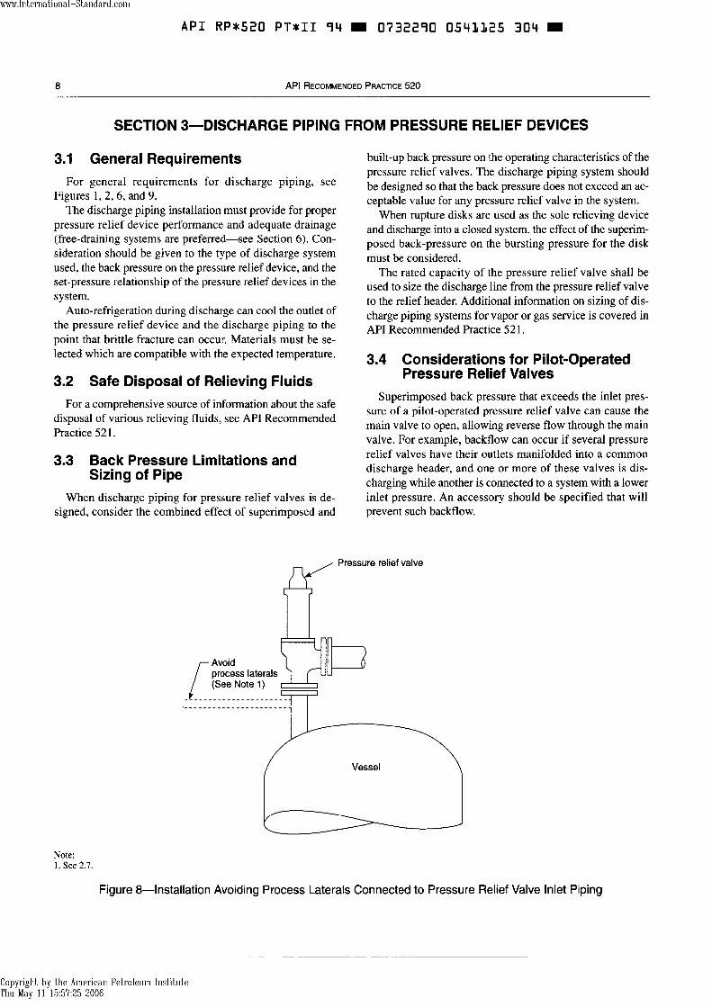
2.7 Process Laterals Connected to Inlet Piping of Pressure Relief Valves
Process laterals should generally not be tonnected to the inlet piping of pressure relief valves (see Figure 8). Exceptions should be analyzed carefully to ensure that the allowable pressure drop at the inlet of the pressure relief valve is not exceeded under simultaneous conditions of rated flow through the pressure relief valve and maximum possi- ble flow through the process lateral.
2.8 Turbulence in Pressure Relief Device Inlets
See 7.3 for information regarding the effects of turbulence on pressure relief valves.
Rupture disk (See Note 1)
I I , Pressure indicator
Excess flow valve
Note: 1. Rupture disk can be either non-fragmenting forward or reverse acting rupture disk (reverse acting shown).
Figure 7-Typical Rupture Disk Assembly Installed in Combination with a Pressure Relief Valve
Copyright by the American Petroleum Institute Thu May 11 15:57:25 2006
www.lnternational-Standard.com
API RP*520 PT*II 94 0732290 054LL25 304
8 API RECOMMENDED PRACTICE 520
SECTION 3-DISCHARGE PIPING FROM PRESSURE RELIEF DEVICES
3.1 General Requirements For general requirements for discharge piping, see
Figures 1, 2,6, and 9. The discharge piping installation must provide for proper
pressure relief device performance and adequate drainage (free-draining systems are preferred-see Section 6). Con- sideration should be given to the type of discharge system used, the back pressure on the pressure relief device, and the set-pressure relationship of the pressure relief devices in the system.
Auto-refrigeration during discharge can cool the outlet of the pressure relief device and the discharge piping to the point that brittle fracture can occur. Materials must be se- lected which are compatible with the expected temperature.
3.2 Safe Disposal of Relieving Fluids
built-up back pressure on the operating characteristics of the pressure relief valves. The discharge piping system should be designed so that the back pressure does not exceed an ac- ceptable value for any pressure relief valve in the system.
When rupture disks are used as the sole relieving device and discharge into a closed system, the effect of the superim- posed back-pressure on the bursting pressure for the disk must be considered.
The rated capacity of the pressure relief valve shall be used to size the discharge line from the pressure relief valve to the relief header. Additional information on sizing of dis- charge piping systems for vapor or gas service is covered in API Recommended Practice 521.
3.4 Considerations for Pilot-Operated Pressure Relief Valves
Superimposed back pressure that exceeds the inlet pres- For a comprehensive source of information about the safe sure of a pilot-operated pressure relief valve can cause the
disposal of various relieving fluids, see API Recommended main valve to open, allowing reverse flow through the main
Practice 521. valve. For example, backflow can occur if several pressure
3.3 Back Pressure Limitations and Sizing of Pipe
relief valves have their outlets manifolded into a common discharge header, and one or more of these valves is dis- charging while another is connected to a system with a lower - -
When discharge piping for pressure relief valves is de- inlet pressure. An accessory should be specified that will signed, consider the combined effect of superimposed and prevent such backflow.
Avoid process laterals (See Note 1)
Vessel
/
Note: 1. See 2.7.
Figure 8-Installation Avoiding Process Laterals Connected to Pressure Relief Valve Inlet Piping
Copyright by the American Petroleum Institute Thu May 11 15:57:25 2006

www.lnternational-Standard.com --
API RP*520 P T * I I 94 0732290 0543326 240
3.5 Stresses that Originate from 3.6 Isolation Valves in the Discharge Discharge Piping Piping
The effects of stresses that originate from discharge piping Isolation valves located in the discharge piping system are discussed in 2.3.1 and 2.3.2. shall be in accordance with the guidelines in Section 4.
SECTION 4-ISOLATION (STOP) VALVES IN PRESSURE RELIEF PIPING
4.1 General Block valves may be used to isolate a pressure relief de-
vice from the equipment it protects or from its downstream disposal system. Since improper use of a block valve may render a pressure relief device inoperative, the design, instal- lation, and management of these isolation block valves should be carefully evaluated to ensure that plant safety is not compromised.
4.2 Application
If a pressure relief device has a service history of leakage, plugging, or other severe problems which affect its perfor- mance, isolation and sparing of the relief device may be pro- vided. This design strategy permits the pressure relief device to be inspected, maintained, or repaired without shutting down the process unit. However, there are potential hazards associated with the use of isolation valves. The ASME Boiler and Pressure Vessel Code, Section VIII, Appendix M, discusses proper application of these valves and the admin- istrative controls which must be in place when isolation block valves are used. Local jurisdictions may have other requirements.
Additional examples of isolation valve installations are given in 4.4.
I 4.3 Isolation Valve Requirements
In addition to previously noted inlet and outlet pressure drop restrictions, all isolation valves located in relief system piping shall meet the following requirements:
a. Valves shall be full bore. b. Valves shall be suitable for the line service classification. c. Valves shall have the capability of being locked or car- sealed open. d. When gate valves are used, they should be installed with stems oriented horizontally or, if this is not feasible, the stem could be oriented downward to a maximum of 45' from the horizontal to keep the gate from falling off and block- ing the flow.
Consider painting the isolation valves a special color or providing other identification.
When isolation valves are installed in pressure relief valve discharge piping, a means to prevent pressure buildup be- tween the pressure relief valve and the isolation valve should be provided (for example, a bleeder valve). Also, the installation of bleed valves should be considered to enable the system to be depressured prior to performing mainte- nance on the system as shown in Figures 9 through 12.
Typical installations of isolation valves under pressure relief valves are shown in Figures 9 through 11.
Consider the installation of an additional relief device, so that 100 percent design relieving capacity is available while any relief device is out of service. Examples of this type of installation are shown in Figures 10 and 11. Consider storing the spare valve until needed to preserve its integrity and al- low bench testing just prior to installation.
When spare relief devices are provided, a mechanical in- terlock or interlocking procedure shall be provided which manages proper opening and closing sequences of the isola- tion valves to ensure that overpressure protection of the ves- sel or equipment is not compromised. Typically the inlet isolation valves for spare relief valves are closed.
Three-way isolation valves are acceptable provided the installation meets the size and inlet pressure drop requirements.
4.4 Examples of lsolation Valve Installations
An isolation valve downstream of a pressure relief device may be installed at battery limits of process units. This is il- lustrated in Figure 12. The purpose of battery limit isolation valves is to allow process units to be removed from service for maintenance while other process units discharging into the main plant flare header remain in service.
Similarly, relief system isolation valves may be used for equipment such as compressors, salt dryers, or coalescers, which are spared and need to be shut down for maintenance while spare equipment remains online (see Figure 13).
4.5 Management Procedures Related to lsolation Valves
Strict management procedures should be in place that will prohibit the inadvertent closing of isolation valves in
Copyright by the American Petroleum Institute Thu May 11 15:57:25 2006

API RPt520 PTxII 94 m 0732290 0541127 187 m
10 API RECOMMENDED PRACTICE 520
relief piping. These procedures should require that the umentation of the required position and reason for the lock opening and closing of the valves be done by an autho- or seal should be provided. rized person. Periodic inspections of isolation valves located in relief
An updated list should be kept of all isolation valves lo- piping should be made which verify the position of valves cated in relief piping which could isolate relief valves. Doc- and the condition of the locking or sealing device.
Isolation valve with provision -/ n for car sealing or locking open (not required for atmospheric discharge) Bonnet vent piping
(See Note 1) for bellows type pressure relief valves, if required (See Note 2)
To closed system or atmospheric 7 piping
-
,
Bleed valve installed ' on valve body (See Note 3)
Nonrecoverable pressure losses not more than 3 percent of set pressure
Typical blinding
eed valve
Isolation valve with provision for car sealing or locking open
Flanged spool piece, if required to elevate PRV
points
Notes: 1. See Section 4. 2. See Section 5. 3. Alternatively, a pipe spool with bleed may be installed
Figure %Typical Pressure Relief Valve Installation with an Isolation Valve
Copyright by the American Petroleum Institute Thu May 11 15:57:25 2006

Vessel
C
-
To closed (isolation valving required) or atmospheric discharge system
I / I
\ \ I
Copyright by the American Petroleum Institute Thu May 11 15:57:25 2006
- -
Typical bleed valve
- Nonrecoverable pressure losses not more than 3 percent of set pressure
v
A A
Figure 10-Typical Pressure Relief Valve Installation Arrangement for 100 Percent Spare Relieving Capacity

API RP*520 P T * I I 94 0732290 0543329 T5T
12 API RECOMMENDED PRACTICE 520
Note: 1. See Section 4.
To closed (isolation valving required) or atmospheric discharge system
Typical isolation valve
car sealing or locking open
- Nonrecoverable
Figure 11-Alternate Pressure Relief Valve Installation Arrangement for 100 Percent Spare Relieving Capacity
\ f
Copyright by the American Petroleum Institute Thu May 11 15:57:25 2006
pressure losses not more than 3 percent of set pressure
I
Vessel

SECTION 5-BONNET OR PILOT VENT PIPING
5.1 Conventional Valves The two types of conventional valves are:
a. Open spring, often used in steam service. b. Closed spring, where the bonnet enclosing the spring is vented internally to the pressure relief valve discharge. The bonnet normally has a tapped vent that is closed off with a threaded plug.
5.2 Balanced Bellows Valves Balanced bellows valves are utilized in applications where
it is necessary to minimize the effect of back pressure on the set pressure and relieving capacity. This is done by balancing
the effect of the back pressure on the top and bottom sides of the disk. This requires the spring to operate at atmospheric pressure.
The bonnets of bellows valves must always be vented to ensure proper functioning of the valve and to provide a tell- tale in the event of a bellows failure. The vent must be de- signed to avoid plugging caused by ice, insects, or other obstructions. When the fluid is flammable, toxic, or corro- sive, the bonnet vent may need to be piped to a safe location.
5.3 Balanced Piston Valves Balanced piston valves are utilized in applications to min-
imize the effect of back pressure, similar to the balanced
Process unit flare Process unit relief : ;;::;;;;;valve 1; header (self draining)
Battery limit
I
To main 4 .C flare header Y' D
Pressure relief valve installation
Isolation (See Note 3) blind point (See Note 2)
Pressure relief 91 d i h f ; valve installation T 3- (See Note 4) x
7
X 7
Pressure vessel A
Pressure vessel B
Notes: 1 . See 4.4. 2. See Figure 8. 3. See Figures 10 and 1 1 . 4. See Figures 2 and 9.
Figure 12-Typical Flare Header Block Valves
Copyright by the American Petroleum Institute Thu May 11 15:57:25 2006

API RP*520 P T * I I 94 0732290 0541131 608
API RECOMMENDED PRACTICE 520
bellows valve. Proper operation depends on cancellation of the back pressure effect on opposing faces of the valve disk and balance piston. Since the piston area is equal to the nozzle seat area, the spring must operate at atmospheric pressure.
Because of the flow of system media past the piston, the bonnets of balanced piston valves should always be vented to atmosphere at a safe location. The amount of flow past the piston into the bonnet depends on the pressure differ- ential between the valve outlet and bonnet. In an installa- tion where superimposed back pressure or built-up back pressure is high, the flow past the piston could be sub-
stantial. This factor must be considered in the design of the bonnet venting.
5.4 Pilot-Operated Valves The pilot is often vented to the atmosphere under operat-
ing conditions, since the discharge during operation is small. When vent discharge to the atmosphere is not permissible, the pilot should be vented either to the discharge piping or through a supplementary piping system to a safe location. When vent piping is designed, avoid the possibility of back pressure on the pilot unless the pilot is a balanced design.
Isolation block valves (See Note 1)
First stage Second stage Third stage
Note: 1. See 4.4.
Figure 1 %Typical Isolation Block Valves for Spare Compressor
Copyright by the American Petroleum Institute Thu May 11 15:57:25 2006
www.lnternational-Standard.com -
API RP*520 P T * I I 94 0732290 0543332 544
SECTION 6-DRAIN PIPING
6.1 Installation Conditions that Require 6.2 Safe Practice for Installation of Drain Piping Drain Piping
Drain piping is normally not required on pressure relief Since drain piping becomes part of the entire venting sys- valves at the valve body connection provided for this tem, precautions that apply to the discharge system apply purpose. The outlet piping to closed systems should be self- similarly to the drain piping. The drain-piping installation draining to a liquid disposal point, thereby eliminating the must not adversely affect the valve performance, and need for a drain from the valve. Drainage must be provided flammable, toxic, or corrosive fluids must be piped to a safe when the discharge is not self-draining and the valve is lo- location. cated where liquids could accumulate at the valve outlet.
SECTION 7-PRESSURE RELIEF DEVICE LOCATION AND POSITION
7.1 Inspection and Maintenance For optimum performance, pressure relief devices must
be serviced and maintained regularly. Details for the care and servicing of specific pressure relief devices are pro- vided in the manufacturer's maintenance bulletins and in API Recommended Practice 576. Pressure relief devices should be located for easy access, removal, and replace- ment so that servicing can be properly handled. Sufficient working space should be provided around the pressure relief device.
7.2 Proximity to Pressure Source The pressure relief device should normally be placed close
to the protected equipment so that the inlet pressure losses to the device are within the allowable limits. For example, where protection of a pressure vessel is involved, mounting the pressure relief device directly on a nozzle on top of the vessel may be necessary. However, on installations that have pressure fluctuations at the pressure source (as with valves on a positive displacement compressor discharge) that peak close to the set pressure of the pressure relief valve or burst pressure of a rupture disk, the pressure relief device should be located farther from the source and in a more stable pres- sure region. (See Section 2 for information related to this subject.)
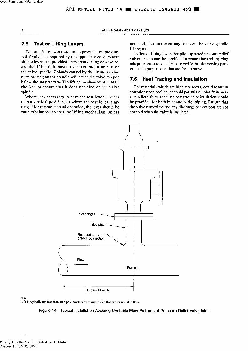
7.3 Proximity to Other Equipment Pressure relief devices should not be located where
unstable flow patterns are present (see Figure 14). The branch entrance where the relief device inlet piping joins the main piping run should have a well-rounded, smooth comer that minimizes turbulence and resistance to flow.
When pressure relief branch connections are mounted near equipment that can cause unstable flow patterns, the
branch connection should be mounted downstream at a dis- tance sufficient to avoid the unstable flow. Examples of devices that cause unstable flow are discussed in 7.3.1 through 7.3.3.
7.3.1 REDUCING STATIONS
Pressure relief devices are often used to protect piping downstream from pressure reducing valves, where unstable flow usually occurs. Other valves and appurtenances in the system may also disturb the flow. This condition cannot be evaluated readily, but unstable flow at valve inlets tends to generate instability.
7.3.2 ORIFICE PLATES AND FLOW NOZZLES
Proximity to orifice plates and flow nozzles may cause ad- verse operation of the pressure relief devices.
7.3.3 OTHER VALVES AND FITTINGS
Proximity to other fittings, such as elbows, may create tur- bulent areas that could result in adverse performance of pres- sure relief devices.
7.4 Mounting Position Pressure relief valves should be mounted in a vertical up-
right position. Installation of a pressure relief valve in other than a vertical upright position may adversely affect its op- eration. The valve manufacturer should be consulted about any other mounting position, since mounting a pressure re- lief valve in other positions may cause a shift in the set pres- sure and a reduction in the degree of seat tightness.
Additionally, another position may permit liquids to col- lect in the spring bonnet. Solidification of these liquids around the spring may interfere with the valve operation.
Copyright by the American Petroleum Institute Thu May 11 15:57:25 2006
API RP*520 P T * I I 94 D 0732290 0543333 480 =
16 API RECOMMENDED PRACTICE 520
7.5 Test or Lifting Levers Test or lifting levers should be provided on pressure
relief valves as required by the applicable code. Where simple levers are provided, they should hang downward, and the lifting fork must not contact the lifting nuts on the valve spindle. Uploads caused by the lifting-mecha- nism bearing on the spindle will cause the valve to open below the set pressure. The lifting mechanism should be checked to ensure that it does not bind on the valve spindle.
Where it is necessary to have the test lever in other than a vertical position, or where the test lever is ar- ranged for remote manual operation, the lever should be counterbalanced so that the lifting mechanism, unless
actuated, does not exert any force on the valve spindle lifting nut.
In lieu of lifting levers for pilot-operated pressure relief valves, means may be specified for connecting and applying adequate pressure to the pilot to verify that the moving parts critical to proper operation are free to move.
7.6 Heat Tracing and Insulation For materials which are highly viscous, could result in
corrosion upon cooling, or could potentially solidify in pres- sure relief valves, adequate heat tracing or insulation should be provided for both inlet and outlet piping. Ensure that the valve nameplate and any discharge or vent port are not covered when the valve is insulated.
lnlet flanges
branch connection
Run pipe
w D (See Note 1)
Note: 1. D is typically not less than 10 pipe diameters from any device that causes unstable flow.
Figure 14--Typical Installation Avoiding Unstable Flow Patterns at Pressure Relief Valve lnlet
Copyright by the American Petroleum Institute Thu May 11 15:57:25 2006
API RP*520 PT*II 94 0732290 0541134 317 =
SECTION 8-BOLTING AND GASKETING
8.1 Care in Installation 8.2 Proper Gasketing and Bolting for Before a pressure relief device is installed, the flanges on
Service Requirements the pressure relief valve or rupture disk holder and the mounting nozzle should be thoroughly cleaned to remove any foreign material that may cause leakage. Where pressure relief devices are too heavy to be readily lifted by hand, the use of proper handling devices will avoid damage to the flange gasket facing. Ring joint and tongue-and-groove joint facings should be handled with extreme care so that the mat- ing sections are not damaged.
The gaskets used must be dimensionally correct for the specific flanges; they must fully clear the pressure relief de- vice inlet and outlet openings.
Gaskets, flange facings, and bolting should meet the service requirements for the pressure and temperature involved. This information can be obtained by refemng to other national standards and to manufacturers' technical catalogs.
When a rupture disk device is installed in the pressure relief system, the flange gasket material and bolting loads may be critical. The disk manufacturer's instructions should be followed for proper performance.
SECTION 9-MULTIPLE PRESSURE RELIEF VALVES WITH STAGGERED SETTINGS
Normal practice is to size a single pressure relief valve to handle the maximum relief from a piece of equipment. How- ever, for some systems, only a fraction of that amount must be relieved through the pressure relief valve during mild up- sets. If the fluid volume under a pressure relief valve is insuf- ficient to sustain the flow, the valve operation will be cyclic and will result in poor performance. The valve's ability to re- seat tightly may be affected.
When capacity variations are frequently encountered in normal operation, one alternate is the use of multiple, smaller pressure relief valves with staggered settings. With this arrangement, the pressure relief valve with the lowest setting will be capable of handling minor upsets, and addi-
tional pressure relief valves will be put in operation as the capacity requirement increases.
For inlet piping to multiple relief valves, the piping which is common to multiple valves must have a flow area which is at least equal to the combined inlet areas of the multiple pressure relief valves connected to it.
Refer to API Recommended Practice 520, Part I, to deter- mine set pressure of the pressure relief valves based on maximum allowable pressure accumulation for multiple valve installations.
An alternate to the use of multiple pressure relief valves with staggered settings is the use of a modulating pilot-oper- ated relief valve.
SECTION 1 0-PRE-INSTALLATION HANDLING AND INSPECTION
10.1 Storage and Handling of Pressure siderable internal damage or misalignment. For valves, seat
Relief Devices tightness may be adversely affected. Rupture disks should be stored in the original shipping
Because cleanliness is essential to the satisfactory container, operation and tightness of a pressure relief valve, take pre- cautions to keep out all foreign materials. Valves should be 10.2 inspection and ~ ~ d i ~ ~ of pressure closed off properly at both inlet and outlet flanges. Take particular care to keep the valve inlet absolutely clean.
Relief Valves
Pressure relief valves should, when possible, be stored in- The condition of all pressure relief valves should be visu- doors on pallets away from dirt and other forms of ally inspected before installation. Consult the manufacturer's contamination. instruction manuals for details relating to the specific valve.
Pressure relief devices should be handled carefully and Ensure that all protective material on the valve flanges and should not be subjected to shocks, which can result in con- any extraneous materials inside the valve body and nozzle
Copyright by the American Petroleum Institute Thu May 11 15:57:25 2006

www.lnternational-Standard.com
API RP*520 P T v I I 94 0732290 0543335 253
18 API RECOMMENDED PRACTICE 520
are completely removed. Bonnet shipping plugs must be re- moved from balanced pressure relief valves. The inlet sur- face must be cleaned, since foreign materials clinging to the inside of the nozzle will be blown across the seats when the valve is operated. Some of these materials may damage the seats or get trapped between the seats in such a way that they cause leakage. Valves should be tested before installation to confirm their set pressure.
10.3 lnspection of Rupture Disk Devices All rupture disk devices should be thoroughly inspected
before installation, according to the manufacturer's instruc- tion manuals. The seating surfaces of the rupture disk holder must be clean, smooth, and undamaged.
Rupture disks should be checked for physical damage to the seating surfaces or the prebulged disk area. Damaged or dented disks should not be used. Apply the proper installa- tion and torquing procedure as recommended by the rupture disk device manufacturer.
On reverse-buckling disks that have knife-blade assem- blies, the knife blades must be checked for physical damage
and sharpness. Nicked or dull blades must not be used. Dam- aged rupture disk holders must be replaced.
10.4 Inspection and Cleaning of Systems Before Installation
Because foreign materials that pass into and through pres- sure relief valves can damage the valve, the systems on which the valves are tested and finally installed must also be inspected and cleaned. New systems in particular are prone to contain welding beads, pipe scale, and other foreign ob- jects that inadvertently get trapped during construction and will destroy the seating surface when the valve opens. The system should be thoroughly cleaned before the pressure re- lief valve is installed.
Pressure relief devices should be removed or isolated be- fore hydrotesting or pneumatic pressure testing of the sys- tem, either by blanking or closing an isolation valve. If an isolation valve is used, the flange at the pressure relief device should be wedged open or a bleed valve provided so that in- advertent leaking through the isolation valve does not dam- age the pressure relief device.
Copyright by the American Petroleum Institute Thu May 11 15:57:25 2006

www.lnternational-Standard.com
API RP*520 P T * I I 94 0732290 054LL3b L9T
Copyright by the American Petroleum Institute Thu May 11 15:57:25 2006

A P I RP*520 PT*II 94 0332290 0541137 026 =
American Petroleum lnstitute 1220 L Street. Northwest
Order No. 822-52024
Copyright by the American Petroleum Institute Thu May 11 15:57:25 2006