s.kopp: nufact ’02, imperial college, london 1 the numi neutrino beam i. status of 0.4mw beam ii....
TRANSCRIPT
S.Kopp: NuFact ’02, Imperial College, London 1
The NuMI Neutrino BeamI. Status of 0.4MW BeamII. Potential for 1.6MWII. What’s it Good For?
Sacha E. Kopp,University of Texas – Austin
for the NuMI/MINOS Collaboration

S.Kopp: NuFact ’02, Imperial College, London 2
•NuMI has 400kW primary proton beam 120 GeV 8.67 sec spill 1.9 sec rep rate
MINOS (Fermilab to Minnesota)
L = 730 km
•Beam Axis 3.32o into the ground at FNAL, exits at Canadian border.•2o off-axis in southern Canada or northern Wisconsin (L = 530 – 950 km)
(12 km)
S.Kopp: NuFact ’02, Imperial College, London 3
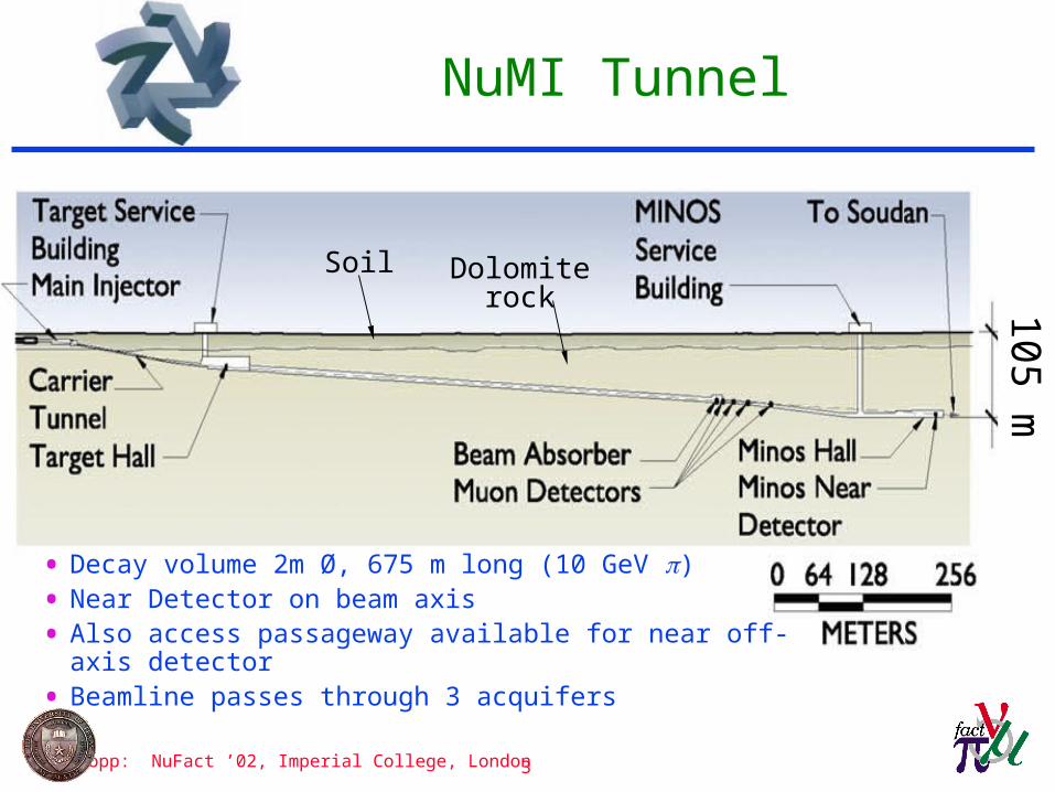
NuMI Tunnel105 m
Soil Dolomiterock
• Decay volume 2m Ø, 675 m long (10 GeV )
• Near Detector on beam axis
• Also access passageway available for near off-axis detector
• Beamline passes through 3 acquifers

S.Kopp: NuFact ’02, Imperial College, London 4
NuMI Extracted Proton Beam
• Passes through acquifers»10-4 losses throughout beamline (magnets activated to 200mrem/hr).»10-6 losses in ‘transition’ soil-rock region (groundwater activation).
• Two major bends»150 mrad bend downward from Main Injector»100 mrad bend upward toward Soudan
• Want to be even more conservative in design»First operation of Main Injector in multi-batch mode»Emittance growth with intensityh, v ~ 25 mm-mrad measured in MI (design for 40)
l, ~ 0.5-0.6 eV-sec measured in MI (design for 1 eV-sec) (p/p ~ 5 10-4 )
»Potential routes to improve proton intensity include batch ‘stacking’Plan for 2-4 larger emittances.

S.Kopp: NuFact ’02, Imperial College, London 5
Improved Extraction Channel
• Added $0.5M in focusing in 40m drift region through soil-rock interface.
Old Design New Design
figures courtesy S.Childress
S.Kopp: NuFact ’02, Imperial College, London 6
Target Hall
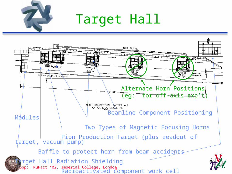
Beamline Component Positioning Modules
Two Types of Magnetic Focusing Horns
Pion Production Target (plus readout of target, vacuum pump)
Baffle to protect horn from beam accidents
Target Hall Radiation Shielding Radioactivated component work cell
Alternate Horn Positions(eg: for off-axis exp’t)
S.Kopp: NuFact ’02, Imperial College, London 7
NuMI Target Hall
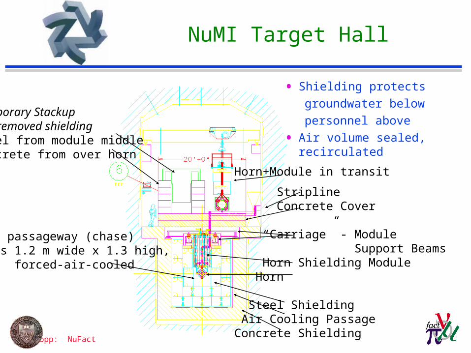
Horn+Module in transit
Stripline Concrete Cover
“Carriage” - Module Support Beams Horn Shielding Module Horn
Steel Shielding Air Cooling PassageConcrete Shielding
Temporary Stackup of removed shieldingSteel from module middle Concrete from over horn
Beam passageway (chase) is 1.2 m wide x 1.3 high, forced-air-cooled
• Shielding protects
groundwater below
personnel above
• Air volume sealed, recirculated

S.Kopp: NuFact ’02, Imperial College, London 8
NuMI Production Target
FNAL design teamJ.Hylen, K.Anderson
FNAL beam testJ.Morgan, H.Le, Alex Kulik, P. Lucas, G. Koizumi
IHEP Protvino design team: V.Garkusha, V.Zarucheisky F.Novoskoltsev, S.Filippov, A.Ryabov, P.Galkin, V.Gres, V.Gurov, V.Lapygin, A.Shalunov, A.Abramov, N.Galyaev, A.Kharlamov, E.Lomakin, V.Zapolsky Target read-out
Budal mode

S.Kopp: NuFact ’02, Imperial College, London 9
Prototype Target Test
•Teeth show no damage after 7x10¹⁷ protons
•3x10⁵ pulses•2x10¹⁸ protons/mm2
(~ 1 NuMI week )
•Max. stress pulses: 1x10¹³/pulse 0.2 mm RMS spot
NuMI Design: 4x10¹³/pulse 0.9 mm spot, 23MPa stress (cf 100MPa limit)
•If go to 1.6MW beam, require spot size 2.0mm-Maintains target temperature-Maintains target stress-Long-term radiation damage?
S.Kopp: NuFact ’02, Imperial College, London 10
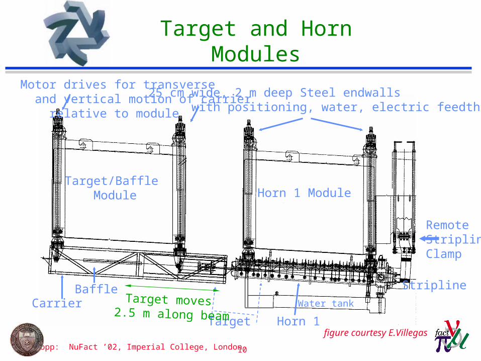
Target and Horn Modules
Water tank
Stripline
RemoteStriplineClamp
Baffle
Target
Target/Baffle Module Horn 1 Module
Horn 1
25 cm wide, 2 m deep Steel endwalls with positioning, water, electric feedthroughs
Motor drives for transverse and vertical motion of carrier relative to module
Carrier Target moves 2.5 m along beam
figure courtesy E.Villegas
S.Kopp: NuFact ’02, Imperial College, London 11
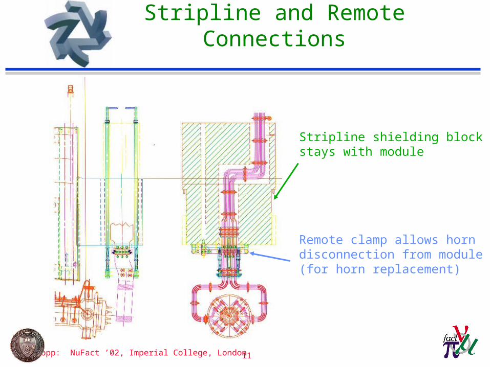
Stripline and Remote Connections
Stripline shielding block stays with module
Remote clamp allows horn disconnection from module (for horn replacement)
S.Kopp: NuFact ’02, Imperial College, London 12
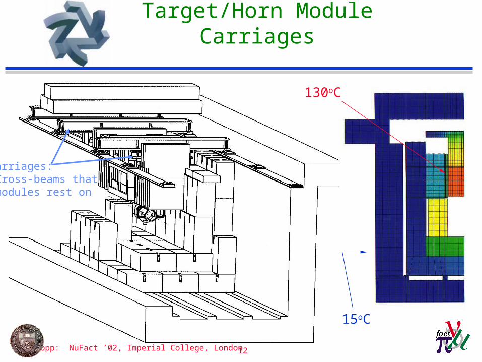
Target/Horn Module Carriages
Carriages: Cross-beams that modules rest on
130oC
15oC
S.Kopp: NuFact ’02, Imperial College, London 13
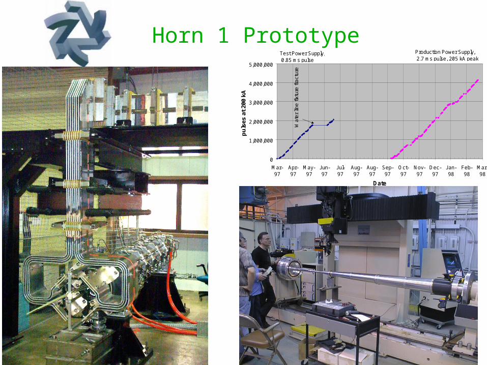
Horn 1 Prototype
0
1,000,000
2,000,000
3,000,000
4,000,000
5,000,000
Mar-97
Apr-97
May-97
J un-97
J ul-97
Aug-97
Aug-97
Sep-97
Oct-97
Nov-97
Dec-97
J an-98
Feb-98
Mar-98
Date(Runs nights and weekends only)
puls
es a
t 20
0 kA
Test Power Supply, 0.85 ms pulse
Production Power Supply, 2.7 ms pulse, 205 kA peak
Wat
er li
ne fi
xtur
e fr
actu
re
S.Kopp: NuFact ’02, Imperial College, London 14
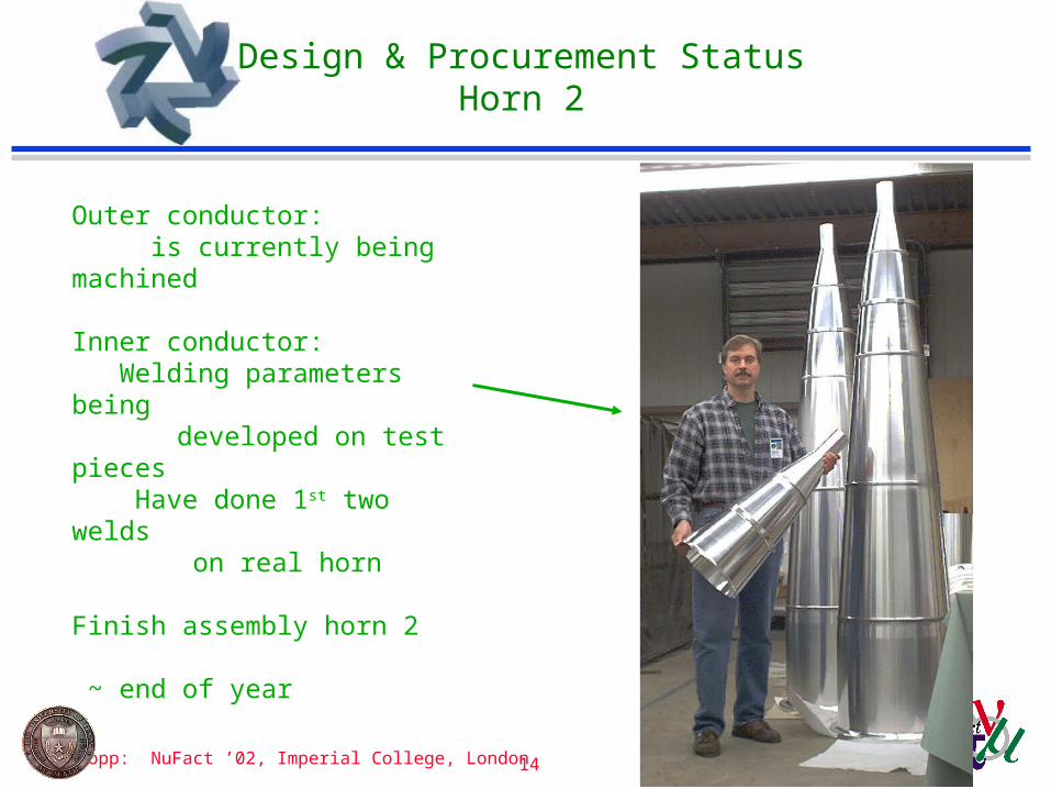
Design & Procurement StatusHorn 2
Outer conductor: is currently being machined
Inner conductor: Welding parameters being developed on test pieces Have done 1st two welds
on real horn
Finish assembly horn 2 ~ end of year
S.Kopp: NuFact ’02, Imperial College, London 15
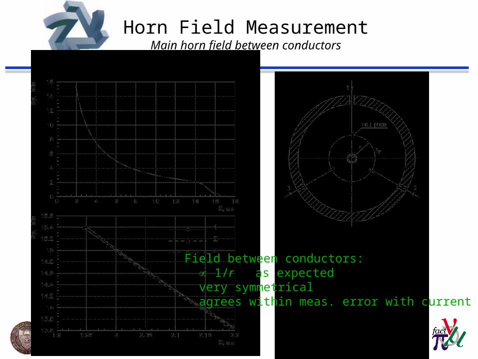
Horn Field MeasurementMain horn field between conductors
Field between conductors: 1/r as expected very symmetrical agrees within meas. error with current

S.Kopp: NuFact ’02, Imperial College, London 16
Horn Field Measurement in ‘field-free’ region through center of horn
Error or fringe field in “field-free”region down center of horn is so smallthat no correction should need to be putinto the Monte Carlo.
Measurement with probemoving along horn axis
2% F/N criterion on flux in M.E. beam (approximately scaled to 0.85 ms test pulse from 2.6 ms operational pulse)
S.Kopp: NuFact ’02, Imperial College, London 17
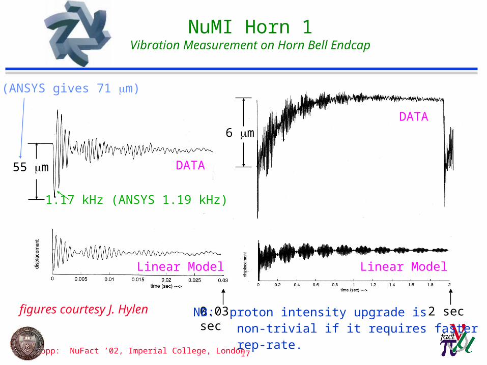
NuMI Horn 1Vibration Measurement on Horn Bell Endcap
6 m
55 m
(ANSYS gives 71 m)
1.17 kHz (ANSYS 1.19 kHz)
DATA
Linear Model
DATA
Linear Model
2 sec0.03 sec NB: proton intensity upgrade is non-trivial if it requires faster rep-rate.
figures courtesy J. Hylen

S.Kopp: NuFact ’02, Imperial College, London 18
TBM in Target Hall (May 2001)
TBM - front
TBM - back
S.Kopp: NuFact ’02, Imperial College, London 19
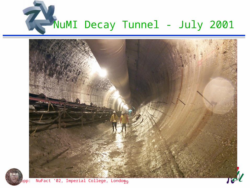
NuMI Decay Tunnel - July 2001

S.Kopp: NuFact ’02, Imperial College, London 20
Decay Pipe
• 2m Ø steel cans, 1 cm wall.
• Reinforced by 4” rings @ 20 ft.
• Decay volume evacuated to ~0.1-1.0 Torr
• Helium-filling is a backup
• Complete decay pipe now in place, welded, inspected.
• Dual entrance window»Inner 1m Ø = 1.5mm Al»Outer 2m Ø = 1.0 cm Fe»Should readily handle increase in beam power (currently designed for beam accident)
S.Kopp: NuFact ’02, Imperial College, London 21
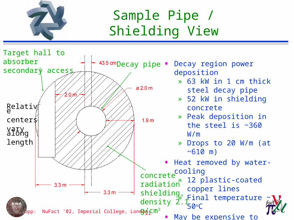
Sample Pipe / Shielding View
concrete radiation shielding, density 2.1 g/cm3
Decay pipe • Decay region power deposition» 63 kW in 1 cm thick steel
decay pipe» 52 kW in shielding concrete» Peak deposition in the steel is
~360 W/m» Drops to 20 W/m (at ~610 m)
• Heat removed by water-cooling» 12 plastic-coated copper lines» Final temperature ~ 50oC
• May be expensive to upgrade for 4 beam intensity.
Target hall to absorber secondary access
Relative centers vary along length
S.Kopp: NuFact ’02, Imperial College, London 22
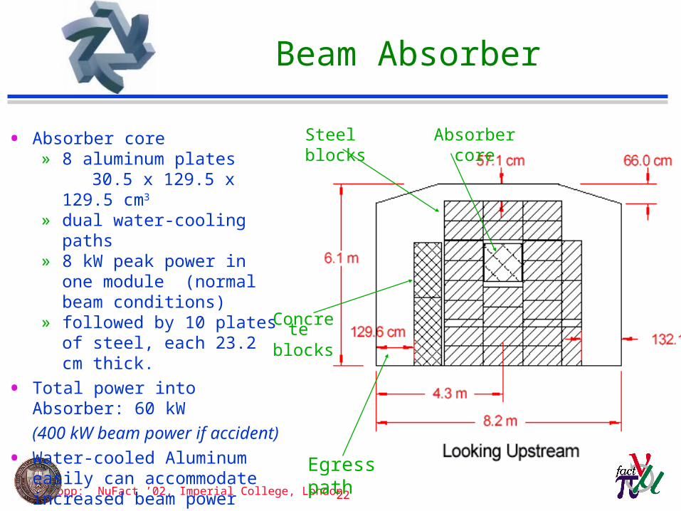
Beam Absorber
Egress path
• Absorber core» 8 aluminum plates 30.5 x 129.5 x 129.5 cm3
» dual water-cooling paths» 8 kW peak power in one module
(normal beam conditions)» followed by 10 plates of steel,
each 23.2 cm thick.
• Total power into Absorber: 60 kW
(400 kW beam power if accident)
• Water-cooled Aluminum easily can accommodate increased beam power from proton upgrad
• Steel is more problematic – require adding water cooling?
Concrete
blocks
Absorber coreSteel blocks

S.Kopp: NuFact ’02, Imperial College, London 23
Summary of NuMI Upgradeability
table courtesy N. Grossman
Item4E13 ppp
(1.9sec rep)8E13 ppp
(1.9sec rep)1.5 E14 ppp (1.9sec rep)
Radiation Issues OKseal chase more
($250K)seal chase more
($500K)
Collimators may need
very likely need (3@ $60K=
$180K)
very likely need (3@ $60K=
$180K)Primary Beam and Power Supplies OK OK OK
Target and Target Cooling OK OKNew Target and Cooling ($750K)
Horns and Cooling OK OK OKTarget Chase Cooling and Shielding OK
cooling for stripline? ($500K)
Cooling for whole chase ($5 million)
Hadron Absorber Cooling OK probably OKAdditional cooling
needed ($1 million)
Decay pipe cooling OK don't knowneed cooling ($1
million??) Additional Cooling ponds may need more may need ($150K) will need ($400k)Total $ 1 million +?? $9 million

S.Kopp: NuFact ’02, Imperial College, London 24
Off-Axis case for Existing NuMI
• Plots assume current neutrino target, horns.
• Variable energy beam can help move peaks dynamically
• Antineutrino running takes factor 3 hit in rate
NuMI ME BeamNuMI ME BeamNuMI LE BeamNuMI LE Beam
figures courtesy M.Messier
S.Kopp: NuFact ’02, Imperial College, London 25
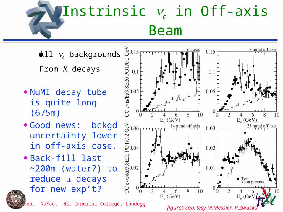
Instrinsic e in Off-axis Beam
• NuMI decay tube is quite long (675m)
• Good news: bckgd uncertainty lower in off-axis case.
• Back-fill last ~200m (water?) to reduce decays for new exp’t?
All e backgrounds
From K decays
figures courtesy M.Messier, R.Zwaska

S.Kopp: NuFact ’02, Imperial College, London 26
e Backgrounds Summary
• Plot assumes |Ue3|2=0.01, m2=3.010-3 eV2.
• NC is all interactions before any identification cuts.
• Detector design requires >10 reduction in NC events?
• For rest of discussion, assume NC reduced to level of beam e.
figure courtesy M.Messier

S.Kopp: NuFact ’02, Imperial College, London 27
Comparison of Exp’ts
• Assume m2 = 3.0 10-3 eV2, sin213=0.1,
• For NuMI, assume a 20kt detector, 85% fid.vol, analysis of low-Z calorimeter
• NuMI can make up for lower proton power, longer baseline because of higher neutrino, pion, cross sections.
NuMI-MINOS, 2 yrs @ 8E20 POT
NuMI Off-Axis,5yrs @ 4E20 POT/yr712 km baseline
JHF Phase I,5yrs @ 0.77MW295 km baseline

S.Kopp: NuFact ’02, Imperial College, London 28
Interpretation of PhaseI Results
• Interpretation of e observation
• Observation would be strengthened by antineutrino running.
Sign(m2)
Sign(m2)
S.Kopp: NuFact ’02, Imperial College, London 29
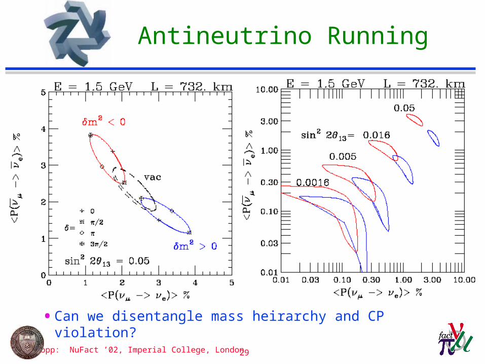
Antineutrino Running
• Can we disentangle mass heirarchy and CP violation?
S.Kopp: NuFact ’02, Imperial College, London 30
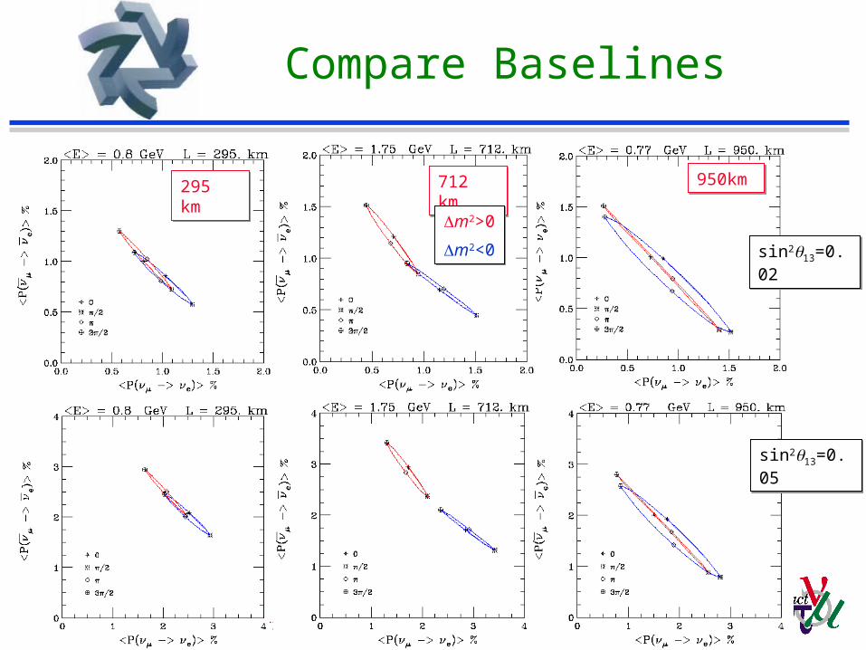
Compare Baselines
950km950km712 km712 km295 km295 km
sin213=0.02sin213=0.02
sin213=0.05sin213=0.05
m2>0
m2<0
m2>0
m2<0
S.Kopp: NuFact ’02, Imperial College, London 31
More Protons for NuMI
• Original baseline 4E13 protons/spill, 4E20/yr.
• Present performance of Booster is 4.5-5.0E12protons/batch (5 batches per MI extraction)
• Possible paths to improvement»Get all 6 Booster batches (post-collider)»Multi-filling of MI (‘stacking’)»Reduce MI acceleration time (requires new RF)
• Potential proton source upgrades -- $200M+»16 GeV ‘proton driver’ »8 GeV proton LINAC (R&D for Linear Collider)
S.Kopp: NuFact ’02, Imperial College, London 32
Summary
• NuMI is substantial investment in US HEP program
• Design is flexible to permit variations, upgrades
• NuMI off-axis exp’t has complementary capabilities to JHF
• Real attack of CP violation requires substantial extensions to existing plans -- JHF-II and NuMI-II»4MW proton beam for JHF, 1.6MW for NuMI»HyperKamiokande, NuMI would have …?
• Lots more extensive documentation:»Letter of Intent to Build an Off-Axis Detector for NuMI,
www-numi.fnal.gov/new_initiatives/new_initiatives.html»“The Proton Driver Design Study”, FERMILAB-TM-2136» G.W.Foster, W. Chou, E. Malamud, FERMILAB-TM2169.»“Physics at FNAL with Stronger Proton Sources”, FERMILAB-FN-720