slash resistant materials - home office
TRANSCRIPT

Slash resistant materials
CAST Publication Number: 008/18
T Payne
C Malbon
A Butler
March 2018


Summary
The first Home Office Slash Resistant Materials Standard was published in 2006 by the
Home Office Scientific Development Branch (HOSDB). This addressed materials designed to
protect against aggressive short-duration swipes of an edged weapon across the body.
Home Office Centre for Applied Science and Technology (CAST)1 has worked alongside law
enforcement end users to develop an updated standard that is more reflective of their
operational needs. CAST also engaged closely with the European Working Group on Slash
Protection to validate scientific rationale within the document.
This standard sets the minimum performance requirements and test methods to evaluate
slash resistant materials.
The key changes from the HOSDB Slash Resistance Standard for UK Police (2006) are:
Protection levels: tiered protection levels, SR1 and SR2, have been introduced to offer
varied protection to different areas of the body, based on risk assessments. This
change gives versatility to the end user to select products that best match their
protection needs.
Assessment criteria: better defined penetration criteria have been introduced to reduce
the need for interpretation.
Specifications: better defined submission requirements to ensure greater consistency,
in accordance with other Home Office Personal Protective Equipment (PPE) standards.
Production quality testing: periodic batch testing has been introduced to ensure the
continued production quality of certified products.
1 Superseded HOSDB on 1 April 2011

Nomenclature
Areal density Mass per unit area (kg.m-2).
Batch A quantity of slash resistant panels produced using materials manufactured in a single production run.
Batch reference A unique reference given to a batch of certified slash resistant panels.
Body side The side of the slash resistant panel that must be worn against the surface of the body.
Contact circuit An electrical circuit between the test blade and the force table to identify when a material sample is penetrated.
Contact plate The plate mounted on the force table, directly covering the load cells, that is part of the circuit created with the test blade to identify penetrations.
Declaration of construction
Document, signed by the manufacturer that declares the construction of a given slash resistant material.
Development testing Any test work conducted by a manufacturer in the development process of slash resistant materials.
Fair strike An impact that adheres to the specified minimum acceptable criteria
in terms of strike placement and energy requirements.
Force table Component of the slash drop test assembly housing load cells and
a contact circuit for penetration measurements.
Garment The item of clothing incorporating the slash resistant material (e.g. gloves, sleeves, trousers).
Investigation An examination of non-conformance to product quality testing requirements.
Model reference A manufacturer’s designation (name, number or other description)
that serves to uniquely identify a specific slash resistant material
construction and design.
Panel A fabricated swatch of certified slash resistant material for use
within garments of clothing.
Penetration Any contact between the test blade and the force table, through slash resistant materials, arising from testing.
Perforation Any impact from the test blade resulting in a complete breach of the slash resistant materials. A perforation is defined as a penetration with a contact duration of greater than 0.2ms.
Production quality testing (PQT)
Periodic testing of certified slash resistant materials to ensure production batches continue to perform at certified levels.
Production quality testing (PQT) reference
A unique reference relating to the specific set of PQT tests that is present on all documentation issued by the test facility and on the PQT document issued by the Home Office. The PQT reference must be displayed on each slash resistant panel label.
Protection level A designation afforded to slash resistant materials that meet the minimum performance levels of the standard following testing.
Redacted technical file Reduced technical file providing information to enable test facilities to conduct pre-test assessments and construction checks.
Serial number A reference uniqely identifying a certified panel of slash resistant material.
Slash attack An aggressive, short-duration swipe of an edged weapon across the body.
Slash resistance The property of a material or product showing resistance to a
deliberate human slash attack by a sharp edged weapon.
Slash sabot The missile used in the guided rail drop test assembly to deliver the
test blade to the slash resistant material target at the appropriate
energy.
Strike face The face of the slash resistant sample determined by the manufacturer as the surface that faces the threat (the side oriented away from the body).
Technical file Comprehensive document containing technical details pertaining to slash resistant materials submitted for certification.
Test blade A standard Stanley® knife blade model 1992™, selected from a
calibrated set and used only once.
Test reference A unique reference relating to the specific set of certification tests present on all documentation issued by the test facility and on the certification document issued by the Home Office. The test reference must be displayed on each slash resistant panel label.
Test sample The slash resistant material submitted by the manufacturer for
testing to this standard.
Test series A complete series of fair strikes on a given model of slash resistant materials.
Warp Longitudinal threads of yarns in a weave.
Weft Transverse thread of yarns in a weave.
Witness material A layer of PolyArt™ paper of specified density, placed between the force table and test sample, used to verify penetrations and perforations recorded during slash testing.

Abbreviations
CAST Centre for Applied Science and Technology
HOSDB Home Office Scientific Development Branch
ISO International Organisation for Standardization
NPCC National Police Chiefs’ Council
PPE Personal Protective Equipment
PQT Production Quality Testing
SR1 Slash Resistance Level 1
SR2 Slash Resistance Level 2

Contents
1. Introduction .............................................................................................................................. 1
1.1. Background ........................................................................................................................... 1
1.2. Rationale ............................................................................................................................... 1
1.3. Scope .................................................................................................................................... 2
2. Manufacturer’s information ..................................................................................................... 3
2.1. General ................................................................................................................................. 3
2.2. Labelling ................................................................................................................................ 4
2.3. Certification process .............................................................................................................. 4
2.4. Declaration ............................................................................................................................ 5
2.5. Home Office approval to test ................................................................................................. 6
2.6. Sample submission ............................................................................................................... 6
2.7. Home Office checks and certification .................................................................................... 6
2.8. Production quality testing ...................................................................................................... 7
3. Submission requirements ....................................................................................................... 8
4. Pre-test assessments .............................................................................................................. 9
4.1. General information ............................................................................................................... 9
4.2. Summary of assessments ..................................................................................................... 9
4.3. Reporting .............................................................................................................................. 9
5. Test configuration ................................................................................................................. 10
5.1. Pre-test conditions............................................................................................................... 10
5.2. Equipment ........................................................................................................................... 10
5.3. Sample preparation ............................................................................................................. 13
5.4. Force table calibration ......................................................................................................... 13
5.5. Data processing .................................................................................................................. 13
6. Test procedure ....................................................................................................................... 14
6.1. General slash testing requirements ..................................................................................... 14
6.2. Protection levels .................................................................................................................. 14
6.3. Test methods ...................................................................................................................... 14
6.4. Test strikes .......................................................................................................................... 16
6.5. Measurements .................................................................................................................... 17
6.6. Perforation assessment criteria ........................................................................................... 17
6.7. Performance assessment .................................................................................................... 17
6.8. Reporting ............................................................................................................................ 17
7. Construction assessments ................................................................................................... 18
7.1. General requirements .......................................................................................................... 18
7.2. Construction assessments .................................................................................................. 18
7.3. Reporting ............................................................................................................................ 18
8. Production quality testing ..................................................................................................... 19
8.1. General requirements .......................................................................................................... 19
8.2. Frequency of assessment ................................................................................................... 19
8.3. Submission requirements .................................................................................................... 19

8.4. Test procedure .................................................................................................................... 19
8.5. Reporting ............................................................................................................................ 20
8.6. Investigations ...................................................................................................................... 20
Acknowledgements ........................................................................................................................... 21
Appendix A – Declaration of construction ....................................................................................... 22
Appendix B – Test equipment and consumables ............................................................................ 23
List of figures
Figure 1: Process map for certification to the 2018 Slash Resistant Materials Standard ........................ 4
Figure 2: Home Office Slash Drop Test Assembly ............................................................................... 10
Figure 3: Slash sabot and its constituent components ......................................................................... 11
Figure 4: Force table and its constituent components .......................................................................... 12
Figure 5: Mounting of test samples ...................................................................................................... 15
Figure 6: (a) Test blade being inserted into the pivot arm; (b) test blade located in pivot arm notches
(clamping plate removed) .................................................................................................................... 15
List of tables
Table 1: Sample submission requirements ............................................................................................ 8
Table 2: Slash protection levels ........................................................................................................... 14
Table 3: Series of test strikes ............................................................................................................... 16

1
1. Introduction
1.1. Background
In violent assaults, edged weapons are typically either employed in a stabbing action, where
the blade is thrust directly at the body,2 or in a slashing action, where the blade is used in a
short-duration swipe across the body.
The Home Office Slash Resistant Materials Standard (2018) supersedes the HOSDB Slash
Resistant Materials Standard (2006)3 and outlines the minimum performance requirements
and test methods for evaluation of slash resistant materials for use by law enforcement.
The work underpinning the 2006 standard was based on research carried out into the
mechanisms behind a human slash attack as well as the velocities and levels of force applied.
This research was translated into a consistent, representative mechanical test to assess
material samples.
1.2. Rationale
Since the inaugural 2006 test standard, the Home Office Centre for Applied Science and
Technology (CAST) has engaged with law enforcement end users, commercial manufacturers
and test facilities to monitor and evaluate its effectiveness and identify areas for potential
improvements.
The main requirement of the standard remained to provide protection to officers from the threat
of a slash attack.
A key new area identified from consultation was the desire for tiered protection levels, which
offer different levels of protection based on the requirements in different regions of the body.
Through liaison with the European Working Group on Slash Protection, two protection levels
have been adopted:
SR1 – offering slash protection to lower-risk areas of the body where an attack would
not be considered life threatening (e.g. hands, outer arms).
SR2 – offering slash protection to higher risk areas of the body where an attack would
be considered life threatening (e.g. neck, groin).
The specifications were also aligned with other Home Office Personal Protective Equipment
(PPE) test standards, increasing their robustness and consistency. Finally, based on
conversations with testing specialists, evaluation and assessment criteria were modified to
enable more objective assessment of product performance.
2 The Home Office Body Armour Standard (2017) outlines the levels of protection required to resist penetration of stab events
from both knife and spike implements. 3 Malbon, C. and Croft, J. (2006) HOSDB Slash Resistance Standard for UK Police, Home Office, London, UK. Publication
No. 48/05. Crown Copyright.

2
1.3. Scope
This standard has been written to address the requirements of UK law enforcement for slash
resistant materials when faced with a slash threat from an edged weapon. This standard tests
material samples of a defined size and not any particular garment. These materials may be
used to provide protection to any region of the body. A comprehensive risk assessment should
be undertaken prior to deciding which levels of protection to adopt for different regions.
Slash resistant materials certified to this standard are deemed to be slash resistant only and
meet the minimum performance requirements specified. It is the responsibility of the end user
to ensure the slash resistant materials address their particular requirements. It is the
responsibility of the manufacturer to ensure the continued quality of their product.
Within this standard, to ensure continued performance in the production of slash resistant
materials, periodic production quality testing (PQT) has been included.
It is to be noted this standard only tests the slash resistance of materials; if any level of stab
protection is required, tests should be conducted in accordance with the Home Office Body
Armour Standard (2017).4
4 Payne, T., O’Rourke, S. and Malbon, C. (2017) Home Office Body Armour Standard, Home Office, London, UK. Publication
No. 012/17. Crown Copyright.

3
2. Manufacturer’s information
2.1. General
This section details the requisite procedures for the certification of slash resistant materials
intended for law enforcement.
Certification only applies to a particular model, manufactured in accordance with the
manufacturer’s technical file and declaration of construction. No changes to the construction
are permitted under this certification without prior notification to the Home Office. All changes
shall be assessed by the Home Office on a case-by-case basis and these may be subject to
further testing, in accordance with the methods documented within this standard. Any sample
which fails in certification cannot be re-submitted using the same construction.
Each panel of certified slash resistant material produced post certification shall have a unique
serial number. Manufacturers are responsible for ensuring continued performance of their
products via their quality assurance process. In addition, manufacturers shall adhere to the
PQT procedures outlined within this standard.
The Home Office reserves the right to request any panel or garment constructed from slash
resistant materials as a result of successful certification testing to this standard. If there are
significant concerns relating to the safety or quality of any slash resistant material, the Home
Office reserves the right to withhold or remove certification.
All certification testing must be performed at one of the Home Office’s accredited test
facilities;5 manufacturers may witness testing of their own products, subject to agreement with
the facility, but are prohibited from interfering with testing.
Details of certified products will be shared on a public database.6 The following information will
be published:
Manufacturer name
Model reference
Protection level(s)
Certification expiry date (date after which the certification is no longer valid and
requires a PQT certificate)
PQT test reference (once minimum test criteria met)
If a manufacturer does not wish for their product to be included on the database, this shall be
made clear during the submission process.
5 Home Office accredited test facilities are detailed on www.gov.uk/government/publications/home-office-slash-resistant-
materials-test-facilities 6 Protective Equipment Database (ped-cast.homeoffice.gov.uk)

4
2.2. Labelling
A label shall be attached to a panel of slash resistant material, including as a minimum:
manufacturer name
date of manufacture
batch reference
model reference
test reference7
serial number
protection level (e.g. SR1)
care and maintenance instructions
Constructed garments that incorporate panels from different models of certified slash resistant
materials shall either have separate labels for each different model used or a single label that
includes the details of each material with reference to the area of the body protected by the
model of slash resistant materials.
2.3. Certification process
Figure 1: Process map for certification to the 2018 Slash Resistant Materials Standard
7 This shall include original certification reference plus the most recent PQT reference (where applicable).
Submission of Declaration
Testing approval
Sample submission
Certificationtests
Presentation of results
Home Office checks
Certificate produced
Publication of results
Enter PQT
Section 2.4
Section 2.5
Section 2.6
Section 6
Section 8
Submit sealed sample to
Home Office
Manufacturer
Home Office
Test Facility
Reference to standard
Section 2.7
Section 2.7
5
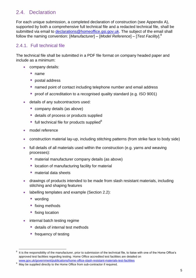
2.4. Declaration
For each unique submission, a completed declaration of construction (see Appendix A),
supported by both a comprehensive full technical file and a redacted technical file, shall be
submitted via email to [email protected]. The subject of the email shall
follow the naming convention: [Manufacturer] – [Model Reference] – [Test Facility].8
2.4.1. Full technical file
The technical file shall be submitted in a PDF file format on company headed paper and
include as a minimum:
company details:
name
postal address
named point of contact including telephone number and email address
proof of accreditation to a recognised quality standard (e.g. ISO 9001)
details of any subcontractors used:
company details (as above)
details of process or products supplied
full technical file for products supplied9
model reference
construction material lay-up, including stitching patterns (from strike face to body side)
full details of all materials used within the construction (e.g. yarns and weaving
processes):
material manufacturer company details (as above)
location of manufacturing facility for material
material data sheets
drawings of products intended to be made from slash resistant materials, including
stitching and shaping features
labelling templates and example (Section 2.2):
wording
fixing methods
fixing location
internal batch testing regime
details of internal test methods
frequency of testing
8 It is the responsibility of the manufacturer, prior to submission of the technical file, to liaise with one of the Home Office’s
approved test facilities regarding testing. Home Office accredited test facilities are detailed on
www.gov.uk/government/publications/home-office-slash-resistant-materials-test-facilities 9 May be supplied directly to the Home Office from sub-contractor if required.
6
2.4.2. Redacted technical file
A redacted technical file shall also be provided to the Home Office for review at the declaration
stage to enable test facility pre-test assessments and construction checks.10 This redacted
technical file shall contain:
type of material
number of layers
construction details (e.g. stitching pattern)
The full technical file will be protectively marked as ‘OFFICIAL SENSITIVE [COMMERCIAL]’
with handling instructions ‘For use by the Home Office and agreed parties, stated manufacturer
and stated test facility only, unless otherwise agreed by all parties’ and kept on record for a
minimum of five years.
2.5. Home Office approval to test
Once the declaration and associated technical files have been submitted, the Home Office will
review and decide whether the submission meets the requirements for certification testing. On
acceptance, the Home Office will authorise the selected Home Office accredited test facility to
initiate the certification testing process.11
In exceptional circumstances the Home Office may provisionally accept submissions prior to
full acceptance of the technical file and declaration. If this is required by the manufacturer, a
full justification explaining why it is necessary shall be provided to the Home Office for
consideration. Certification will not be completed until all documentation is accepted by the
Home Office.
2.6. Sample submission
On approval of the declaration, the manufacturer shall send slash resistant material samples,
corresponding to the requirements of Section 3, for testing to their chosen Home Office
accredited test facility. It is the manufacturer’s responsibility to ensure that the appropriate
quantity of test samples is provided to the accredited test facility. These samples shall be
accompanied with the redacted technical file (Section 2.4.2).
2.7. Home Office checks and certification
On receipt of test reports from the accredited test facility, the Home Office will independently
review them and, where applicable, determine the appropriate protection level. If successful,
the Home Office will then issue the manufacturer with a certificate detailing the outcomes of
the test and pertinent information on the performance of the slash resistant materials. This
shall include:
manufacturer’s name
manufacturer’s address
areal density
10
The manufacturer is responsible for ensuring any confidentiality agreement with their selected test facility is in place, as
required. 11
Any testing conducted prior to receipt of Home Office authorisation will be considered as development testing only and will not
form part of the certification testing process. The use of development testing results as part of certification is not permitted.
7
protection level achieved
original test facility reference
current PQT test reference
issue date
expiry date
On certification, manufacturers shall send a sealed sample of the certified slash resistant
material to the Home Office for audit purposes.
2.8. Production quality testing
Once a model has been certified, it is automatically subject to the PQT protocol. Independent
assessments are mandated at specified intervals to ensure the performance of the materials
during production remains at the certified levels. Details of the threshold frequencies for PQT
and test methods are documented in Section 8.

8
3. Submission requirements
All samples submitted for testing shall be of dimensions 150 × 300mm (length × width).12
The construction of the samples shall conform exactly to the description detailed in the
technical file. If the slash resistant materials are manufactured from multiple layers of material,
they should be fastened (e.g. stitched) in the same manner as intended on the final
manufactured panel or garment of PPE.
The samples required for certification testing are detailed in Table 1.
Table 1: Sample submission requirements
Sample configuration Quantity of samples
Weft horizontal 3
Weft vertical 3
Weft 30° off horizontal 3
Weft 45° off horizontal 3
All samples shall be marked with the strike face and direction of weft.
In instances where the material is not woven, 12 samples shall still be submitted for testing.
The sample orientation shall be varied for each set of three tests in accordance with the
orientations specified in Table 1.
12
If sample packs of these sizes cannot be manufactured, please contact the Home Office.

9
4. Pre-test assessments
4.1. General information
On submission of samples for testing, test facilities shall be supplied with a redacted technical
file from the manufacturer containing the details specified in Section 2.4.2. This technical file
shall be used in assessments to enable comparisons with the panels.
4.2. Summary of assessments
4.2.1. Inspection
Initially, on receipt of samples from the manufacturer, a visual inspection shall be performed to
assess general quality of construction. Defects such as tears, fraying and stitching separation
shall be recorded.
A photograph of the label shall be taken at this stage and reported to the Home Office.
4.2.2. Areal density
Prior to testing, all submitted samples shall be weighed (to the nearest gram) on a set of
calibrated scales, accurate to ± 1.0g. The length and width of the submitted panels shall then
be measured (to the nearest millimetre) with the panels laid flat without tension to provide
exact sample dimensions, which can be used to calculate a surface area. The areal density of
each sample shall be calculated using Equation (1).
𝐴𝑟𝑒𝑎𝑙 𝐷𝑒𝑛𝑠𝑖𝑡𝑦 (𝑘𝑔. 𝑚−2) = (𝑚𝑎𝑠𝑠 𝑜𝑓 𝑠𝑎𝑚𝑝𝑙𝑒 (𝑘𝑔)
𝑎𝑟𝑒𝑎 𝑜𝑓 𝑠𝑎𝑚𝑝𝑙𝑒 (𝑚2)) (1)
4.3. Reporting
Inspection notes and areal densities shall be recorded in the template provided by the Home
Office along with any associated relevant information (e.g. photographs). This spreadsheet
shall be submitted with test reports on completion of testing.
All test reports will be protectively marked as ‘OFFICIAL SENSITIVE [COMMERCIAL]’ with
handling instructions ‘For use by the Home Office and agreed parties, stated manufacturer and
stated test facility only, unless otherwise agreed by all parties’ and kept on record for a
minimum of five years.

10
5. Test configuration
5.1. Pre-test conditions
The test area and storage rooms shall be maintained at a temperature of 20 ± 3°C with relative
humidity of 55 ± 25%. The working temperature and relative humidity of all areas shall be
recorded on the test report.
5.2. Equipment
5.2.1. Overview
Slash testing is conducted using a linear-guided sabot with a protruding knife end-effector.
This sabot is raised on the guided rails and released. It then falls, under the influence of
gravity, until it impacts the test sample which is mounted onto a force table at an angle of 2°
from the vertical.
The guided drop assembly shall be rigidly secured to a supporting wall or frame with care taken
to ensure that it is mounted vertically. The force table component shall be mounted rigidly to a
solid base. Drawings of the guided drop assembly, slash sabot and force table are available on
request from the Home Office. A graphical illustration of the assembly is shown in Figure 2.
Figure 2: Home Office Slash Drop Test Assembly
Guide Rails
Slash Sabot
Force Table

11
5.2.2. Slash sabot
5.2.2.1. Overview
The slash sabot shall consist of a test blade mounted on a pivot arm within a nylon housing
(Figure 3). The nylon housing is designed with geometric features to restrict rotational
movement whilst ensuring minimal friction with the guide rails during testing. The slash sabot
with all components shall have a total mass of 2000 ± 50g.
Figure 3: Slash sabot and its constituent components
5.2.2.2. Test blade
The test blade is a Stanley® knife blade model 1992™. Each blade shall be selected from a set
which has been subject to a 1% batch test for edge sharpness at a certified test facility in
accordance with ISO 8442.5 using a 25mm stroke length. Test blades shall possess an initial
cutting performance of 75 to 85mm.
Prior to use, each blade shall be visually inspected for defects and wiped clean with an
alcohol-based degreasing wipe or similar, taking care not to damage the tip. A blade shall be
used only once; following each slash it shall be replaced.
5.2.2.3. Pivot arm mechanism
The test blade is mounted on a supporting pivot arm mechanism in the slash sabot. This pivot
arm is designed to hold the test blade at an angle of 30 ± 1° from the horizontal when at rest.
On impact with the force table, the compression of the test blade is limited by a calibrated
spring (Appendix B) between the piston and the nylon housing which, on compression,
ensures a representative force is applied to the sample. The pivot arm ensures the
compression forces acting on the spring damper mechanism are perpendicular.
The calibrated spring shall be replaced after each test series.
Test Blade
Pivot Arm
Nylon Housing
Pivot Point

12
5.2.3. Force table
The force table is a rigid component in the slash test assembly, comprising of two
piezoresistive load cells attached to a contact plate. The force table is mounted on a hinged
arm that opens to enable test sample installation and locks at a position 2° from the vertical,
prior to testing. An electrical connection is made to the contact plate to enable a circuit to be
made. An image of the force table is shown in Figure 4.
The load cells shall be pre-loaded to a force at least 30% of the rated value when installed and
shall be connected to a charge amplifier, which processes the summed signals from the
sensors to a data collection device.
The force table is configured to ensure a minimum force of 120N is achieved within 200mm of
contact with the force plate.
All load cells shall be calibrated in accordance with a recognised national or international
standard.
The area to either side of the contact plate shall be built up with PlastazoteTM LD33 closed-cell
polyethylene foam to provide representative support to the test sample. This shall create a
surface extending the full length of the plate and a minimum width of 150mm either side of the
contact plate.
Figure 4: Force table and its constituent components
5.2.4. Contact circuit
An electrical circuit is used to identify when the material sample is penetrated and perforated.
An electrical current is applied to the test blade through the pivot arm mechanism during
testing and a circuit is formed when the test blade is in direct contact with the force table.
Measurements of electrical contact shall be recorded, using a suitable data collection device, at
the same temporal frequency as the load cells in the force table. The measurements shall also
be triggered at the same instant as the load cell such that recordings can be synchronised.
Contact Plate Load Cells
Housing
Supporting Foam

13
5.2.5. Velocity measurement
All velocities shall be recorded when the tip of the test blade is 25 ± 5mm from the surface of
the test sample. The velocity of each strike shall be recorded in metres per second (m.s-1),
reported to two decimal places.
The velocity measurement system shall be measured to an accuracy of ± 0.1m.s-1. It is
recommended that a non-contact method such as a light gate system is adopted with a
minimum sample rate of 30kHz and a base length of 50 ± 2mm. Alternative systems may be
used; however, prior to use, details of the system must be submitted to the Home Office and
approved as an appropriate method.
Velocity measurement equipment shall be calibrated to a recognised national or international
standard.
5.3. Sample preparation
5.3.1. Conditioning panels
All materials shall be placed in an environment held at a temperature of 20 ± 3°C and a relative
humidity of 55 ± 25% for a minimum of 12 hours prior to testing. Samples shall be laid flat at all
times when conditioning and stacked in piles of no more than four.
5.3.2. Marking panels
Prior to testing, the impact location on all samples shall be marked with a small reference on
the horizontal centreline at the top of the sample.
5.4. Force table calibration
Prior to any test series, static force table calibrations shall be performed. Loads of 6.0 ± 0.1kg
and 12.0 ± 0.1kg shall be applied to the contact plate. For each calibration, the force plate shall
be laid horizontal and the mass shall be positioned on the centre of the contact plate, directly
bisecting the load cells. Within five seconds the mass shall be removed and the voltage drop
shall be recorded. This procedure shall be repeated three times for each mass. The sensitivity
of the load cell at each mass shall then be calculated using Equation (2).
𝐹𝑜𝑟𝑐𝑒 𝑇𝑎𝑏𝑙𝑒 𝑆𝑒𝑛𝑠𝑖𝑡𝑖𝑣𝑖𝑡𝑦 =
𝑀𝑒𝑎𝑛 𝑉𝑜𝑙𝑡𝑎𝑔𝑒 𝐷𝑟𝑜𝑝 (𝑉)
𝑀𝑎𝑠𝑠 𝐴𝑝𝑝𝑙𝑖𝑒𝑑 (𝑘𝑔) ∗ 9.81 (2)
The mean of the two sensitivity values shall then be calculated and used.
It is the responsibility of the test facility to ensure the operational function of the force table.
5.5. Data processing
For load cell data recorded, a 3kHz low pass filter shall be applied to reduce artefacts of high
frequency noise.

14
6. Test procedure
6.1. General slash testing requirements
6.1.1. Performance assessment criteria
All slash resistant materials shall not exceed the permissible perforation force levels or
maximum perforation durations defined in Table 2 for the associated protection level being
assessed.
6.1.2. Fair strike
A fair strike shall be recorded if:
the energy of the impact falls within the defined tolerance in Table 2
the strike is a minimum of 50mm from either edge of the sample
Any strike that does not meet the fair strike criteria will be classed as unfair and repeated.
6.2. Protection levels
There are two protection levels for slash resistant materials: SR1 and SR2. The associated
minimum permissible perforation forces and maximum perforation durations for each are
shown in Table 2.
Table 2: Slash protection levels
Protection level
Energy Minimum perforation force (single strike)
Minimum mean perforation force (all strikes)
Maximum perforation duration
SR1 36 ± 2J 30N 40N 1.7ms at ≤ 80N
SR2 36 ± 2J 60N 80N 1.1ms at ≤ 160N
6.3. Test methods
6.3.1. Mounting of samples
The test samples shall be clamped securely onto the force table, as shown in Figure 5. A
single sheet of 75g.m-2 PolyartTM paper (see Appendix B) shall be attached using adhesive
tape to the top edge on the rear of the test sample.

15
Figure 5: Mounting of test samples
6.3.2. Blade insertion
The test blade shall be inserted into supporting pivot arm, as shown in Figure 6, and secured
using the clamping plate. The following procedure shall be adopted:
1. Loosen the three screws that hold the clamping plate onto the pivot arm.
2. Carefully slide the blade into the gap between the pivot arm and the clamping plate
(Figure 6a).
3. Adjust the blade so that it slots into the notches in the slash arm (Figure 6b) (these
cannot be seen under normal conditions).
4. Using a suitable tool, tighten the three screws whilst carefully supporting the blade until
it is securely held.
Care must be taken during the installation process not to contact or damage the tip of the
blade being used for the test.
Figure 6: (a) Test blade being inserted into the pivot arm; (b) test blade located in pivot arm notches (clamping plate removed)
Clamping Point
Slash Resistant Material Sample
(a) (b)
16
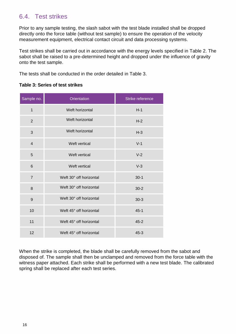
6.4. Test strikes
Prior to any sample testing, the slash sabot with the test blade installed shall be dropped
directly onto the force table (without test sample) to ensure the operation of the velocity
measurement equipment, electrical contact circuit and data processing systems.
Test strikes shall be carried out in accordance with the energy levels specified in Table 2. The
sabot shall be raised to a pre-determined height and dropped under the influence of gravity
onto the test sample.
The tests shall be conducted in the order detailed in Table 3.
Table 3: Series of test strikes
Sample no. Orientation Strike reference
1 Weft horizontal H-1
2 Weft horizontal H-2
3 Weft horizontal H-3
4 Weft vertical V-1
5 Weft vertical V-2
6 Weft vertical V-3
7 Weft 30° off horizontal 30-1
8 Weft 30° off horizontal 30-2
9 Weft 30° off horizontal 30-3
10 Weft 45° off horizontal 45-1
11 Weft 45° off horizontal 45-2
12 Weft 45° off horizontal 45-3
When the strike is completed, the blade shall be carefully removed from the sabot and
disposed of. The sample shall then be unclamped and removed from the force table with the
witness paper attached. Each strike shall be performed with a new test blade. The calibrated
spring shall be replaced after each test series.

17
6.5. Measurements
After each slash test, force-time data and electrical contact data shall be recorded. This data
shall be processed to determine:
time of penetration occurrence
duration of contact
maximum force measured prior to penetration
Witness paper shall be reviewed following each test to verify the penetrations recorded on the
electrical contact. If there are any significant variations, please contact the Home Office.
6.6. Perforation assessment criteria
It has been observed from previous test data that very short-duration penetrations may be
elicited in tests on certain materials that do not constitute a breach of the sample. The
parameters derived from the force-time data shall be used to identify when a significant
penetration of the test sample has occurred; this shall be known as a perforation.
A perforation shall be considered as any penetration with a contact duration of greater than
0.2ms.
Once the point of first perforation has been identified in a test, the maximum force measured
prior to perforation shall be recorded. If this is a force greater than 120N, 120N shall be
recorded on the test report. Similarly, if no perforation occurs during the test, a force of 120N
shall be recorded.
6.7. Performance assessment
Following a test series on a given model, the data shall be analysed to identify:
the minimum force at which the test sample was perforated in a single test
the mean force at which the test sample was perforated across all tests
instances where the duration of perforation exceeds the limits in Table 2 and the
maximum force recorded prior to this perforation
This information shall be used to classify the materials into a protection level. The classification
criteria are outlined in Table 2. The sample must meet all criteria from the required protection
level to be awarded the classification.
6.8. Reporting
The completed test report shall be sent to the Home Office alongside any associated relevant
information (e.g. photographs) on completion of tests.
All test reports will be protectively marked as ‘OFFICIAL SENSITIVE [COMMERCIAL]’ with
handling instructions ‘For use by the Home Office and agreed parties, stated manufacturer and
stated test facility only, unless otherwise agreed by all parties’ and kept on record for a
minimum of five years.

18
7. Construction assessments
7.1. General requirements
On completion of the testing, all submitted samples shall be assessed by the test facility to
ensure the construction is the same as that declared in the redacted technical file (Section
2.4.2).
Any discrepancies shall be recorded and reported to the Home Office and the manufacturer.
Should these discrepancies be deemed significant by the Home Office, the samples shall be
sent to the Home Office for checks.
Following construction assessments, the test facility shall store the panels for a period of six
months post certification at which point they shall be returned to the manufacturer.
The Home Office reserves the right to request any sample from the test facility for audit
checks.
7.2. Construction assessments
Following testing, each sample pack shall be physically separated to expose the individual
material layers. At this stage, the construction methods and, where applicable, stitching
patterns detailed in the redacted technical file shall be assessed. Subsequently, the materials
and layer constructions shall be assessed against those specified in the technical file.
Any irregularities in construction shall be photographed and reported to the Home Office.
7.3. Reporting
Details from the construction assessments shall be recorded in a test report along with any
associated relevant information (e.g. photographs).
All test reports will be protectively marked as ‘OFFICIAL SENSITIVE [COMMERCIAL]’ with
handling instructions ‘For use by the Home Office and agreed parties, stated manufacturer and
stated test facility only, unless otherwise agreed by all parties’ and kept on record for a
minimum of five years.
19
8. Production quality testing
8.1. General requirements
PQT is a quality assurance tool designed to periodically assess the performance of certified in-
production slash resistant materials and ensure they remain at their certified level. This
process outlines the formal quality testing which shall be conducted at one of the Home Office
accredited test facilities.13
Home Office PQT checks are an independent check of a product only. It is the responsibility of
the manufacturer to ensure that all materials produced perform as intended through their own
quality assurance procedure. This must be detailed in the technical file during certification. The
Home Office may request internal quality assurance records for a given model at any time.
PQT shall be performed on all certified slash resistant materials at intervals outlined in
Section 8.2.
Once the specified production milestones have been reached, panels shall be submitted for
assessment within a maximum time period of four weeks. All panels submitted for PQT must
be taken from the same production run.
Following PQT, test results shall be supplied to the Home Office for assessment and approval.
The Home Office reserves the right to request an investigation (Section 8.6) and/or remove
certification at any time if the manufacturer fails to comply with PQT or if a product fails PQT.
8.2. Frequency of assessment
Initial PQT assessments of any slash resistant panel shall be conducted in the first post-
certification production run. This shall be performed at one of the Home Office accredited
independent test facilities.
All certified materials shall undergo re-assessment after two years have elapsed, effective from
the date of the previous set of successful PQT tests.
8.3. Submission requirements
Eight panels shall be submitted for PQT, two from each configuration: weft horizontal, weft
vertical, 45° off weft and 30° off weft.
8.4. Test procedure
All testing shall be conducted in accordance with the methods outlined in Section 6. Any non-
conformance with the testing shall be investigated in accordance with Section 8.6.
13
Home Office accredited test facilities are detailed on https://www.gov.uk/government/publications/home-office-slash-
resistant-materials-test-facilities.
20
Pre-test assessments and construction assessments shall also be conducted in accordance
with Sections 4 and 7 respectively.
8.5. Reporting
PQT test reports shall be sent to the Home Office alongside any associated relevant
information (e.g. photographs) on completion of tests.
All test reports will be protectively marked as ‘OFFICIAL SENSITIVE [COMMERCIAL]’ with
handling instructions ‘For use by the Home Office and agreed parties, stated manufacturer and
stated test facility only, unless otherwise agreed by all parties’ and kept on record for a
minimum of five years.
8.6. Investigations
PQT investigations shall commence following non-conformance to PQT test requirements. In
these circumstances, manufacture of products using this material shall be suspended and the
PQT batch must not be sold prior to the conclusion of the investigation.
The test facility shall provide testing results to the Home Office and the manufacturer. Test
samples relating to the non-conformance shall be sent to the Home Office.
It is the responsibility of the manufacturer to conduct an investigation and adequately satisfy
the Home Office, with supporting evidence, of the rationale for the failed tests. The
investigation shall identify and address the cause of the failure and whether other batches may
have been affected.
If the cause of failure is determined and the issue relates only to the PQT batch, this may be
rectified before the batch undergoes a full re-test (certification).
If the cause of failure cannot be determined and the non-conformance only relates to the PQT
batch, this batch shall be quarantined/destroyed. Internal quality records shall be sought in
such investigations. The next batch produced shall undergo a full re-test (certification).
If, however, the cause of failure cannot be determined or rectified, the affected batches shall
either be upgraded with additional protective materials (and undergo a full re-test –
certification) or withdrawn.

21
Acknowledgements
The authors would like to acknowledge Cranfield University for the original work conducted
using human volunteers to quantify the characteristics of a typical slash attack, on which this
standard is based. Further acknowledgement must also be given to Dr Celia Watson for her
peer review on this document.

22
Appendix A – Declaration of construction
Declaration of Construction of Slash Resistant Materials to Home Office Slash Resistant Materials Standard 2018
When completed this document will be classified as:
OFFICIAL SENSITIVE [COMMERCIAL] for use by Home Office and agreed parties, and stated
manufacturer only, unless agreed by both parties
Manufacturer: Model Reference:
Complete details of material to be included in technical file and associated data sheets
Layer number Material
Strike Face
Body Side
Cover
description
Carrier
description
[Manufacturer] hereby declare that all slash resistant materials produced as model [Model
Reference] will comprise the same materials and construction as specified in the construction
declaration and technical file. All slash resistant materials will meet the labelling requirements in
accordance with Section 2.2 of Home Office Slash Resistant Materials Standard (2018) Publication
No. 008/18.
Signed and dated [Manufacturer]:

23
Appendix B – Test equipment and consumables
Item description Specification
Test blade Stanley® knife blade model 1992TM
Sabot damper spring
Spring type: Round wire compression
Design to: BS 1726-1:1987
Tolerance: BS 1726-1:2002
Material: BS 5216 Patented Carbon
End type: Closed and ground
Wire diameter: 1.83mm
Outside diameter: 18.29mm
Spring rate: 8.41N.mm-1
Free length: 22.23mm
PolyartTM paper
Arbjobex Headquarters 32, Avenue Pierre Grenier 92517Boulonge Billancourt cedex France
Standard matt white 75/95
75g.m-2
0.95mm thickness
Contact circuit 5V power supply with a 10kΩ resistor

ISBN: 978-1-78655-612-7
© Crown copyright 2018
This publication is licensed under the terms of the Open Government Licence v3.0
except where otherwise stated. To view this licence, visit
nationalarchives.gov.uk/doc/open-government-licence/version/3 or write to the
Information Policy Team, The National Archives, Kew, London TW9 4DU, or email:
Where we have identified any third party copyright information you will need to obtain
permission from the copyright holders concerned.