sm 2019 - newmar€¦ · 79 doors, handles, and chimes 80 entrance steps 81 exterior lights 82...
TRANSCRIPT

2019
sm
sm


TABLE OF CONTENTSNOTICE
This Owner's Guide is published and printed from Newmar's online knowledgebase. For the most up-to-dateversion of this content, and for more product-specific information, how-to articles, and troubleshootinginformation, please refer to Newgle. All of the information in Newgle is believed to be accurate at the time ofpublication. However, it may be necessary to make revisions, and Newmar reserves the right to make anysuch changes without notice or obligation.
INTRODUCTION1 A Letter from Our Family to Yours2 Introduction to Newgle5 Safety Notices in Newgle5 Warranty and Service6 About Your Owner's Information Package6 About the Delivery Process
SAFETY9 Placards and Labels10 Before Driving Away10 Driving in Dangerous Conditions11 Seat Belt Safety13 Fire Safety14 Carbon Monoxide Safety15 LP Safety17 Emergency Exits
APPLIANCES22242425
Cooktops and RangesFireplacesMicrowaves and Convection Ovens Refrigerators, Freezers and Ice MakersWashers and Dryers
CHASSIS27 Ford27 Fuel Systems29 Leveling Systems34 Wheels and Tires
ELECTRICAL37414753545457
© 2018 Copyright Newmar Corporation. All rights reserved. For the most up-to-date version of this content, and for more product-specific information, please refer to Newgle.
606061646465
12 Volt Electrical System120 Volt Electrical SystemBatteriesCord ReelsEnergy Management SystemsFuse Panels and Wiring Diagrams GeneratorsInverters and ConvertersLightingReceptacles and Accessory Chargers Solar PowerTransfer Switches and Surge ProtectorsElectrical Appliance Typical Amp Draw List
ELECTRONICS67686969
Camera and Video Monitoring SystemsHolding Tank MonitoringNavigation SystemsWiFi Systems
ENTERTAINMENT SYSTEMS7272737373747474
Antennas, Cable, and Satellite SystemsBlu-ray PlayersDash Receivers, CD Players, and StereosDVD PlayersHeadphones, Speakers, and AmplifiersInfrared Receivers, Remotes, and SwitchersStereo Receivers and Home Theater SystemsTelevisions
REV. 180228
25

EXTERIOR77 Air Horns77 Awnings78 Compartments79 Doors, Handles, and Chimes80 Entrance Steps81 Exterior Lights82 Hitches and Towing Components82 Ladders83 Mirrors84 Paint, Roof, and Siding85 Windows87 Windshields88 Wiper Systems
HVAC89 Air Conditioning and Heat, Dash90 Air Conditioning and Heat, Roof91 Fans and Ventilation91 Furnaces92 Thermostats
INTERIOR959597
Beds and MattressesCabinetry and WoodworkCeiling and Walls
© 2018 Copyright Newmar Corporation. All rights reserved. For the most up-to-date version of this content, and for more product-specific information, please refer to Newgle.
979899101103103104104
Countertops and BacksplashesFabrics and MaterialsFlooringFurnitureInterior Doors and HardwareInterior FurnishingsInterior Steps and Step CoversShades and Window Coverings
PLUMBING107107108112113113114115116119121
Faucets and FixturesFiltersFresh Water SystemHose ReelsPower Washers, Sprayers, and Exterior ShowersSinksToiletsTubs and Shower EnclosuresWaste Water SystemWater HeatersWater Pumps
SLIDEOUTS125128132136139
Electric Bedroom SlideoutsElectric Flat Floor SlideoutsElectric Full Wall SlideoutsElectric Kitchen SlideoutsElectric Wardrobe Slideouts
CARE AND MAINTENANCE143144145148149150
151151153154156
How to Wash and Dry a CoachWaxing and Polishing a CoachHow to Winterize a CoachHow to De-Winterize a CoachHow to Sanitize the Complete Water SystemUltrafabrics Cleaning Guidelines for Flexsteel and Villa FurnitureHow to Clean Exterior ChromeHow to Weigh Your CoachRoutine Maintenance ScheduleService RecordFuel, Oil, and MPG Record

© 2018 Copyright Newmar Corporation. All rights reserved. For the most up-to-date version of this content, and for more product-specific information, please refer to Newgle.

© 2018 Copyright Newmar Corporation. All rights reserved. For the most up-to-date version of this content, and for more product-specific information, please refer to Newgle.

A LETTER FROM OUR FAMILY TO YOURSWelcome to the exciting world of recreational vehicles andthe growing Newmar family! Congratulations on yourpurchase of a Newmar product! Your coach proudly carriesthe Newmar torch, as a new generation of RV’ing begins.We share your excitement at this moment, and with youlook forward to the years and miles of adventure the RVlifestyle offers you in your coach.Whether camping at your favorite remote fishing hole ortailgating at the big game with your friends, Newmar is withyou 24 hours a day, 7 days a week.
THE NEWMAR LEGACYYour new coach was built with care using today's technology and old world craftsmanship. At Newmar, we strive to buildvehicles that are safe, dependable, and comfortable. Born on Christian principles, and from the desire to build not themost, but the best, the legacy associated with the name Newmar is one of family pride and quality. It is the culminationof decades of RV design and building experience. We take humble pride in our history of innovation. We introduced theindustry to the first slideout rooms, and continued our tradition of innovation with the first flush floor slideout in amotorized coach and the smooth, seamless fiberglass body. Your coach is at the forefront of current technology, built bythe skilled hands and quality conscious eyes of craftsmen.At Newmar, we recognize that a craftsman’s final product is only as good as the materials they use, so we are selectiveabout what we put into our coaches. We start with a foundation forged in the strength of steel and aluminum. We fill itwith beautiful, durable hardwoods, and select name brand appliances and components, then build it on a chassis built tostand the test of time. Then we finish our units with an artist’s gentle touch.
THE NEWMAR WARRANTYYour coach has been built to the highest standards. That’s why we back it with a 12-month limited warranty, the bestwarranty in the industry. A heritage of quality and dependability makes it easy for us to offer that kind of coverage.Please read the Newmar Limited Warranty and all other component warranties that apply to the equipment installed onyour unit. The limited warranties issued by the chassis and component manufacturers require periodic service andmaintenance. The owner's failure to provide this service and/or maintenance may result in the loss of warrantycoverage. Be sure to file the appropriate registration card with the component manufacturer as described with theindividual instruction booklets to activate the warranties on the components within your Newmar coach.
CUSTOMER SUPPORTCarefully read both the instructions in your Owner’s Guide, as well as the booklets supplied by the chassis andcomponent manufacturers for important operation, safety, and maintenance information. This Owner’s Guide should bekept in your vehicle for quick reference. Take time to get acquainted with your unit and how it operates. Should you haveany questions, consult your dealer or the Newmar customer support team. In addition to the assistance you receive fromthe customer support team, we are also excited to announce a new approach to customer service: Newgle.Your coach owner's guide is printed directly from Newgle, Newmar's dynamic, multi-faceted knowledge center createdspecifically for Newmar coach owners and certified technicians. Because content pertaining to your coach is constantlyevolving and changing, the only way we can provide you with access to the most up-to-date and relevant information isby linking you directly to it! Much of our information comes directly from the manufacturer of the items that are specific toyour coach model and year, so we urge you to check out the site for any additional information that may not (currently)be included in your owner's guide. For more information, refer to the Introduction to Newgle article.Our customers are extremely important to us, and we will make every effort necessary to ensure your satisfaction.
CONTACT NEWMAR• Phone: 800.731.8300• Mail: P.O. Box 30 | Nappanee, Indiana 46550-0030• Websites: www.newmarcorp.com and https://newgle.newmarcorp.com
© 2018 Copyright Newmar Corporation. All rights reserved. For the most up-to-date version of this content, and for more product-specific information, please refer to Newgle. 1

INTRODUCTION TO NEWGLEWelcome to the wonderful world of Newgle! As aNewmar coach owner, Newgle provides you with access tocontent pertaining to your specific model and year. Whetheryou are using the search bar or the drop down navigationfeatured on every page, you have the ability to locate theinformation you need with the click of a button.
Newgle consists of 12 categories, dozens of sub-categories, and thousands of item-specific links connecting you directlyto the manufacturer of the items in your coach! Content is regularly added and is only available to current Newmarowners and certified technicians. Feel free to browse and explore our mobile-friendly website from your tablet orsmartphone.
IMPORTANTNewgle is an ever-changing knowledgebase. The Newgle team strives to introduce new features and contentregularly to improve the site. The included screenshots and navigational instructions may change withoutnotice. Always refer to Newgle for the most up-to-date version of this content.
HOW DO I ACCESS NEWGLE?Visit Newgle at https://newgle.newmarcorp.com to register for an account.Because you now own a Newmar coach, click the link associated with anowner account, "Coach Owner - Newgle Access Request." You will beasked to provide your coach information and some basic contactinformation, allowing the Newgle Team to verify ownership and set up anaccount just for you!Once your account has been created, you will receive a verification email,which will include your username and password, transporting you to aone-of-a-kind world of knowledge. If you have any questions regardingyour login information, please contact your Newmar Model Specialist.
HOW DO I NAVIGATE THE SITE?The Newgle logo is available in the upper left corner ofevery page throughout the site. Click on the logo at any timeto return to the Home page. The Home page displays youruser information and provides an introduction to your coach(model and year), as well as access to the Newgle searchfunction, drop-down menus, and category blocks, which arecrucial for easy navigation throughout the site.
NEWGLE IT! SEARCH
The Newgle it! search bar is also available on every page,making it possible for you to conveniently initiate a searchanytime from anywhere within the site.By using search terms, such as the product name or manufacturer, or by typing in the model number or Newmar partnumber, you can visit the relevant Newgle pages listed in the search results immediately.
© 2018 Copyright Newmar Corporation. All rights reserved. For the most up-to-date version of this content, and for more product-specific information, please refer to Newgle. 2

DROP-DOWN MENUChoosing a category from the drop-down navigation menualong the top of the page will take you to the landing pagefor that category. From here, you can drill down to the sub-category level, allowing you to view the contents of eachcategory.
CATEGORY BLOCKSChoosing a category block on the Home page will take youto the landing page for that category. Just like the drop-down menu, you can drill down to the sub-category level,allowing you to view the contents of each category.To view more sub-categories, click on the set of threehorizontal dots at the end of the list. This will expand theview so all of the sub-categories are visible. Click on the setof three horizontal dots again to collapse the sub-categorylist.
WHAT TYPE OF INFORMATION WILL I FIND?CATEGORIESEach of the categories includes a brief overview of the type of informationyou will find within the category and the layers beneath it. The overview mayinclude dangers, warnings, cautions, and important notices to highlightparticular aspects of your coach that may require additional attention.Many categories also include images of labels (some of which may be notedas examples only) that may be posted throughout your coach or on yourcomponents.Click on a sub-category block below the information to view more detailedinformation about a particular component within the Entertainment Systemscategory, such as Blu-ray Players.
SUB-CATEGORIESEach sub-category includes basic information about thetopic at hand, which may include the location, operation,and function of a particular system or component withinyour coach.Below the information is a list of "Item Home Pages" basedon the items relevant to your coach year and model. Thesepages are titled using the manufacturers of the products.Some sub-categories will only display one or two item homepages, such as the Blu-ray Players, because that is the onlyequipment installed in your coach for that model and year.
© 2018 Copyright Newmar Corporation. All rights reserved. For the most up-to-date version of this content, and for more product-specific information, please refer to Newgle. 3

NOTICEAll of the information in Newgle is believed to beaccurate at the time of publication. However, it may benecessary to make revisions, and Newmar reservesthe right to make any such changes without notice orobligation.
ITEM HOME PAGES AND ITEMSOnce an Item Home Page is selected (i.e. Sony Blu-rayPlayers), you may see basic information about thatmanufacturer and component, such as operatinginstructions, care and maintenance, etc. You will also see alist of "Item Home Page Items (IHPi's), or the componentsthat are available (standard or optional) in your coach basedon the model and year.Each item will be titled "Manufacturer Model Number ::Manufacturer and Item Description :: Newmar PartNumber." Special Notices (discontinued items, etc.),Features pertaining to the part or component, Newmar'sWarranty Information, Manufacturer Site Links, and thechart of Relevant Coaches (model and year) that the part orcomponent was installed in (standard or optional) areavailable on every item when it is available.
On the right side, you will see the product name andmanufacturer, the Newmar part number, as well as a photofrom ComNet, Newmar's parts catalog (when available).Within the Manufacturer Site Links section, you will haveaccess to associated links to the direct manufacturer orsupplier for the following information, when available:
• Operation, Installation, and Maintenance Manuals• Care and Maintenance Guides• Product Specifications & Reviews• Safety Information & Warranty Registration Forms• Troubleshooting Guides and Service Manuals• Parts and Accessories Catalogs• FAQ's & Videos• Technical Guides (when available to the public)
WHAT IF I CAN'T FIND WHAT I NEED?Our dedicated, full-time Newgle staff is working to provide you with accessto more model-specific information directly from the manufacturers asquickly as we can.By leaving feedback and requests for specific information at the bottom ofany page, you have the opportunity to directly impact how we prioritize ourefforts!
© 2018 Copyright Newmar Corporation. All rights reserved. For the most up-to-date version of this content, and for more product-specific information, please refer to Newgle. 4

NOTICEAs a Newmar coach owner, Newgle provides you with access to content pertaining to your model and year ofcoach. You may see information not relevant to your specific coach throughout the site; however, thisinformation may pertain to other floorplans and/or was available as optional equipment for your coach modeland year.
SAFETY NOTICES IN NEWGLEReference is made to the following terms throughout Newgle and the Owner's Guide: Danger, Warning, Caution,Important, and Notice. These terms indicate important information that must be understood and followed.
SAFETY DEFINITIONS
DANGERDANGER indicates an imminently hazardous situation that, if not avoided, will result in death or seriousinjury. Failure to observe a DANGER may also result in damage to the equipment or unit.
WARNINGWARNING indicates a potentially hazardous situation that, if not avoided, could result in death or seriousinjury. Failure to observe a WARNING may also result in damage to the equipment or unit.
CAUTIONCAUTION indicates a potentially hazardous situation that, if not avoided, may result in minor or moderateinjury. Failure to observe a CAUTION may also result in damage to the equipment or unit.
IMPORTANTIMPORTANT notices are not related to personal injury, but provide additional information to make a stepeasier or clearer.
NOTICENOTICE indicates information that is not necessary or required, but may prove to be helpful.
WARRANTY AND SERVICE“Customers say they’re loyal to us because they trust us to stand behind our products – fromsupport, parts and service to paying our warranties. It feels good to own a coach that has all of thatbehind it.” The only warranty offered by Newmar Corporation is set forth in the written limitedwarranty that applies to this vehicle. The Newmar Corporation Limited Warranty was provided to youby your selling dealer prior to purchase.
IMPORTANTWarranty service required needs to be completed during the term of the warranty. Service work scheduled orperformed after the expiration of the Newmar warranty will not be covered.
© 2018 Copyright Newmar Corporation. All rights reserved. For the most up-to-date version of this content, and for more product-specific information, please refer to Newgle. 5

The limited warranties issued by the chassis and component manufacturers require periodic service and maintenance.The owner’s failure to provide this service and/or maintenance may result in the loss of warranty coverage.The owner should review the Newmar Corporation Limited Warranty and other manufacturers’ limited warranties on allcomponents applicable to this vehicle. To activate the warranties on the components within your Newmar recreationalvehicle, be sure to file the appropriate registration card with the component manufacturer.If, for any reason, you have a problem obtaining satisfactory and timely warranty service that may substantially impairthe use, value, or safety of your Newmar coach, please call Newmar Customer Service toll free at (800)731-8300.
CUSTOMER RELATIONSIf you wish to schedule maintenance work, schedule service work, or order parts you should notify your local authorizedNewmar Service Center to set up an appointment. If you are unsure of the location of the closest authorized ServiceCenter, contact Newmar Customer Service. You may also write to:Newmar Corporation | Warranty Department | P.O. Box 30 | Nappanee, IN 46550
ABOUT YOUR OWNER'S INFORMATION PACKAGEIncluded in your Owner's Information package are valuable documents about your vehicle and its components andsystems. The Newmar Owner’s Guide does not cover every possible detail of the equipment (standard and/or optional)installed on or in your coach. Consulting the booklets and instruction manuals in this package will help you safelyoperate, maintain, and troubleshoot these items.
IMPORTANTRead all of the information and understand the safety and operating instructions included in the Owner’sInformation Package. To assure full warranty coverage, it is essential that all maintenance instructions arefollowed.
An information sheet is provided containing importantinformation about your coach for your convenience.
• Your coach's Newmar Serial Number. This numberis needed whenever making an appointment for serviceor ordering parts through your Newmar Dealer orService Center.• Your coach's Vehicle Identification Number (VIN).The VIN is the legal identification of the completedvehicle and is used by the state for vehicle registration.• Your coach's Year, Model, Type, and Floorplan.• Manufacturer, Model, and Serial Number of factory-installed equipment.
IMPORTANTThe manufacturer, model, and serial number of the appliances and accessories installed at the factory in yourcoach are listed on this label for convenience. It is important that the label remains in the coach foridentification purposes. Do not remove or relocate this label.
ABOUT THE DELIVERY PROCESSThe customer is responsible for regular and proper maintenance of the vehicle. Properly maintaining your vehicle willprevent conditions arising from neglect that are not covered by your Newmar limited warranty. The maintenanceguidelines in this manual and any other applicable manual should be followed. It is your responsibility and obligation toreturn the vehicle to an authorized dealer for repairs and service.Throughout the manufacturing process, your vehicle has been inspected by Newmar qualified technicians. However, ourfinal inspection at the factory is not to be the last one. The pre-delivery inspection and systems check your dealerperforms are the final inspections done to the unit prior to you receiving your new coach. Your dealer may assist you in
© 2018 Copyright Newmar Corporation. All rights reserved. For the most up-to-date version of this content, and for more product-specific information, please refer to Newgle. 6

understanding the limited warranties and with completing all warranty forms for the various appliances and accessoriesinstalled in your unit.
CUSTOMER RESPONSIBILITIESTo assist you in avoiding problems with your vehicle, we recommend you do the following:
1. Read the warranty. Go over it thoroughly with your dealer.2. Inspect the vehicle. Do not accept delivery until you have gone through the coach with the dealer. Newmar hasprovided a check list to be used during retail delivery. Check each item on the list, and make sure the dealer doesthe same. Do not sign this checklist until you have checked off each item.
NOTICEThe sales literature versus actual specifics to the vehicle’s measurements, weights, or quantities may vary.
3. Ask questions about anything that you do not understand concerning your recreational vehicle.4. Responsible Use. Your vehicle is designed to be used for recreational or temporary living purposes. It is notdesigned to be used as a full-time residence or for commercial use. Commercial use means using as a businessasset, such as a mobile office or using the vehicle for lease/rental purposes.
DEALER RESPONSIBILITIES1. A pre-delivery inspection and systems check: thoroughly inspecting the vehicle and the operation of the factoryinstalled components.2. A customer walk-through to familiarize the customer with the vehicle, its systems and components, and theiroperation.3. Delivery of the Owner’s Information Package. This package contains the warranty cards and registrations forthe vehicle and factory- installed components that carry a separate warranty. The detailed operating andmaintenance instructions on these components are also included in this package.4. Assisting the customer in completing the component registration forms, at the customer’s request. To avoidloss of warranty coverage, the dealer should review the limited warranty provisions with the customer, stressingthe importance of filing warranty cards and registrations to the component manufacturers within the prescribedtime limit.5. Providing the customer with information regarding warranty and non-warranty work on the vehicle, as wellas its separately warranted components, whether the customer is in or out of the area.
© 2018 Copyright Newmar Corporation. All rights reserved. For the most up-to-date version of this content, and for more product-specific information, please refer to Newgle. 7

8© 2018 Copyright Newmar Corporation. All rights reserved. For the most up-to-date version of this content, and for more product-specific information, please refer to Newgle.

SAFETYThis section provides information about Newmar's compliance requirements, placards and labels,and seatbelt safety. It also includes information about the safety components installed in yourcoach, including your smoke and carbon monoxide detectors, emergency exits, and much more.
COMPLIANCE REQUIREMENTSNewmar motorhomes meet or exceed compliance for the following agencies:
CANADA• Canada Motor Vehicle Safety Standards (CMVSS)• Federal Motor Carrier Safety Administration (CSA Z 240)• Canadian Electrical Code through QAI Laboratories
UNITED STATES• Federal Motor Vehicle Safety Standards (FMVSS)• Oregon, Nebraska, and Washington State Seals• National Fire Protection Association (NFPA) 1192 through Recreation Vehicle Industry Association (RVIA)• National Fire Protection Association (NFPA) 70 National Electrical Code• Ford Qualified Vehicle Modifiers (QVM) (Ford Chassis Only)• Carb Compliant Phase 2
NATIONAL HIGHWAY TRAFFIC SAFETY ADMINISTRATION
IMPORTANTIf you believe that your vehicle has a significant defect which could cause a crash or could cause injury ordeath, inform the National Highway Traffic Safety Administration (NHTSA) and Newmar Corporationimmediately.
CONTACT NHTSA1. Phone: Auto Safety Hotline (toll free) at 1-888-327-4236 (TTY #1-800-424-9153)2. Write: NHTSA, 400 Seventh Street S.W., Washington, DC 205903. Website: http://www.safecar.gov.
PLACARDS AND LABELSA variety of placards and labels are located throughout your coach. These are installed to aid in the operation of acomponent, or to warn of potential dangers while operating a specific appliance, accessory, or system.
IMPORTANTReading, understanding, and heeding all such labels and placards is critical to the safe, efficient use of yourcoach.
© 2018 Copyright Newmar Corporation. All rights reserved. For the most up-to-date version of this content, and for more product-specific information, please refer to Newgle. 9

These will include warningsregarding the electricalsystem, propane gas system,fueling the coach, and muchmore. It is important to readthese placards and warningsto ensure the safety andproper operation of the item.Examples of such labels areprovided; one of these labelsmay be affixed adjacent toyour propane tank, ifequipped.
BEFORE DRIVING AWAYProvides a brief list of procedures that will aid in your driving safety and extend the life of your coach.
WARNINGPrior to driving your vehicle, be sure you have read your entire owner’s guide and that you understand yourvehicle’s equipment completely. Read and understand all of the instructions and precautions in this owner’sguide and the chassis manufacturer owner’s manual before operating your new coach.
Listed below are some safety precautions that must be adhered to while your coach is in motion. These precautions, aswell as others that involve possible damage to equipment, are also listed in the appropriate areas in this manual.There are various adjustments that need to be made prior to starting and moving the vehicle. Among them are thedriver’s seat, the tilt steering, and the exterior side view mirrors, as well as checking the rear view monitoring system. Inaddition, the following procedures will aid in your driving safety and extend your equipment’s life.
• Windows, mirrors, and light lenses are to be clean and unobstructed.• Tires should be checked for proper cold inflation pressure.• Wheel lug nuts should be checked for proper tightness.• Fluid levels, including engine oil, transmission fluid, coolant, power steering fluid, brake fluid, and windshieldwasher solvent, should be checked and filled, if necessary.• Disconnect the unit. Store the sewer and water supply hoses, as well as shoreline power cords.• Secure all cargo in the storage compartments in the event of a sudden stop.• Verify that the step has retracted prior to engine ignition.• Know the overall height of your coach to avoid overhead damage from low clearance bridges, overpasses,awnings, etc.
DRIVING IN DANGEROUS CONDITIONSWARNING
The cruise control is not to be operated on icy roads, extremely wet roads, winding roads, heavy traffic, or inany other traffic situation where a constant speed cannot be maintained.
WARNINGWhile driving on slippery surfaces, use care when accelerating or decelerating. Skidding and loss of vehiclecontrol may be the result of abrupt changes in speed.
© 2018 Copyright Newmar Corporation. All rights reserved. For the most up-to-date version of this content, and for more product-specific information, please refer to Newgle. 10

WARNINGDriving through water deep enough to wet the brakes may affect the stopping distance or cause the vehicle topull to one side. If you have driven through deep water, check the brake operation in a safe area to be surethey have not been affected.
WARNINGNever operate a vehicle if a difference in braking efficiency is noticeable. Extreme terrain and adverse weathermay affect the handling and/or performance of your vehicle.
SEAT BELT SAFETYOne of the most important safety features in your vehicle is the restraint system. Research has shown that seat beltssave lives. And they can reduce the seriousness of injuries in a collision. Some of the worst injuries happen whenpeople are thrown from the vehicle. Everyone in a motor vehicle needs to be buckled up at all times.
IMPORTANTThese brief operation instructions are for quick reference only. Any quick start instructions provided shouldnot take the place of the complete Operation Manual provided by this item's manufacturer.
WARNINGIt is extremely dangerous to ride in a cargo area, inside or outside of a vehicle. In a collision, people riding inthese areas are more likely to be seriously injured or killed. Do not allow people to ride in any area of yourvehicle that is not equipped with seats and seat belts. Be sure everyone in your vehicle is in a seat and isusing a seat belt properly.
HOW TO OPERATE YOUR SEAT BELTS AND RESTRAINT SYSTEM
WARNINGIf you wear your safety belt improperly, both the effectiveness and comfort will decrease.
OPERATING INSTRUCTIONS FOR LAP/SHOULDER COMBINATION RESTRAINTS1. Enter the vehicle and close the door. Sit back, and adjust the seat.2. The latch plate of the belt is above the back of your seat. Grasp the latch plate, and pull out the belt. Slide thelatch plate up the webbing as far as necessary to make the belt go around your lap.3. When the belt is long enough to fit, insert the latch plate into the buckle until you hear a “click.”4. Position the lap belt across your thigh, below your abdomen. If you need the lap portion tighter, pull up a bit onthe shoulder part. A snug belt reduces the risk of sliding under the belt in a collision. Position the shoulder belt onyour chest so that it is comfortable and not resting on your neck. The retractor will withdraw any slack in the belt.5. To release the belt, push the release button on the buckle.
NOTICESome shoulder belts can be adjusted upward or downward to help position the belt away from your neck.Push on the anchorage cover to release it, and then move it up or down to the position that serves you best.
© 2018 Copyright Newmar Corporation. All rights reserved. For the most up-to-date version of this content, and for more product-specific information, please refer to Newgle. 11

OPERATING INSTRUCTIONS FOR LAP BELT RESTRAINTS WITHOUT A SHOULDERHARNESS
WARNINGAlways wear your seat belt when the vehicle is in operation.
1. Slide the latch up the webbing as far as necessary to make the belt go around your lap.2. Insert the latch plate into the buckle until you hear a “click.”3. Adjust and position the belt low and snug across your hips by removing the slack from the belt.4. To release the belt, push the release button on the buckle.
IMPORTANTEach belt is intended to restrain only one person at a time. Do not put two people under one belt.
CAUTIONNever attempt to restrain a child in your lap using the lap belt around both you and the child. The child couldbe severely injured or killed in the event of a collision.
IMPORTANTSeat belts are matched sets. Do not mix or use this belt or parts of this belt with other types of seat belts.
CHILD RESTRAINTS
IMPORTANTEveryone in your vehicle needs to be buckled up at all times. Every state in the United States and all Canadianprovinces require that small children ride in proper restraint systems. This is the law, and you can beprosecuted for ignoring it.
There are different sizes and types of restraints for children from newborn to near-adult size children. Use the restraintthat is correct for your child:
• The restraint must be appropriate for your child's weight and height. Check the label on the restraint for this, too.• Carefully follow the instructions that come with the restraint. If you install the restraint improperly, it may not workwhen you need it.• Buckle the child into the restraint exactly as the manufacturer's instructions have directed.
HOW TO MAINTAIN YOUR SEAT BELTS AND RESTRAINT SYSTEMPeriodically examine your restraint equipment to be sure it functions correctly and to be sure there are no worn orbroken components that either needs repair or replacement. Damaged parts must be replaced immediately. Do notdisassemble or modify the system.
WARNINGA frayed or torn belt could rip apart in a collision and leave you with no protection. Inspect the belt systemperiodically, checking for cuts, frays, or loose parts. Damaged parts must be replaced immediately. Do notdisassemble or modify the system. Seat belt assemblies must be replaced after an accident if they have beendamaged (bent retractor, torn webbing, etc.)
© 2018 Copyright Newmar Corporation. All rights reserved. For the most up-to-date version of this content, and for more product-specific information, please refer to Newgle. 12

Restraint equipment must be replaced after an accident if they have been damaged. If there is any question regardingbelt or retractor condition, replace the belt. It is a good idea to have your restraint system inspected during each periodicscheduled maintenance session. If the belts need cleaning, use a mild soap solution or lukewarm water. Do not removethe belts from the vehicle to wash them.
WARNINGDo not bleach, dye or clean the belts with chemical solvents or abrasive cleaners. This may severely weakenthe fabric. In a crash, they might not be able to provide adequate protection.
FIRE SAFETYThe possibility of fire existsin all areas of life, and therecreational lifestyle is noexception. Recreationalvehicles are complexmachines made up of manymaterials, some of whichare flammable. Like mosthazards, the possibility offire can be minimized, if nottotally eliminated byrecognizing the danger andpracticing common sensesafety and maintenancehabits. For safety reasons,your unit is furnished withboth a fire extinguisher anda smoke alarm.
DANGERIf a fire occurs in the vehicle, evacuate the vehicle as quickly and as safely as possible. Consider the causeand the severity of the fire and the risk involved before trying to extinguish it. If the fire is major or fuel fed,move away from and stand clear of the vehicle and wait for emergency assistance to arrive.
SMOKE DETECTORSThe smoke detector installed in your coach is operated on a 9 volt battery. The smoke detector is mounted on the ceilingin the living area of the unit. Read the operating instructions for details on the testing and care for this important safetydevice.Test the smoke detector after the unit has been in storage, before each trip, and at least once a week during use. Checkyour smoke detector for the manufacturer’s expiration date. The battery needs to be tested periodically and replacedonce a year and/or when the low battery signal sounds.When cleaning the case on any of the detectors, use a damp cloth or paper towel. Do not spray cleaners or wax directlyinto the case as it may cause false alarms.
IMPORTANTThe detector should never be disabled because of nuisance or false alarm from cooking smoke or a dustyfurnace. Ventilate the unit with fresh air and the alarm will shut off. Never disconnect or remove the batteryfrom the smoke alarm.
© 2018 Copyright Newmar Corporation. All rights reserved. For the most up-to-date version of this content, and for more product-specific information, please refer to Newgle. 13

FIRE EXTINGUISHERSThe fire extinguisher is rated for Class B (grease, gasoline, diesel fuel, flammable liquids) and Class C (electrical) fires.These are the most common types of fires in vehicles. Fire extinguishers are mechanical, pressurized devices. Caremust be exercised when they are handled.The extinguisher should be inspected at least once a month. More frequent inspections may be required if theextinguisher is exposed to the weather or to possible tampering. Do not test the extinguisher by partially discharging, asit will cause a loss of pressure. Your fire extinguisher must be maintained as the operator’s manual instructs for properand safe operation.Read the operator’s manual and the instructions on the fire extinguisher. Be sure to know how and when to use theextinguisher and where it is located.
DANGERFailure to comply could result in an increased risk of fire, explosion, asphyxiation, serious injury, or death.
CARBON MONOXIDE SAFETYCarbon monoxide is a colorless, tasteless, odorless gas. It is a by-product of the burning of fossil fuels (gasoline,propane gas, diesel fuel, etc.). The chassis and generator engines, furnaces, water heater, propane gas refrigerator,and range produce carbon monoxide constantly while they are operating.
IMPORTANTThese brief operation instructions are for quick reference only. Any quick start instructions provided shouldnot take the place of the complete Operation Manual provided by this item's manufacturer.
DANGERCarbon monoxide is deadly. Read and understand the following precautions, as well as any warning labels inyour coach, to protect yourself and others from the effects of carbon monoxide poisoning.
If you, or anyone else, experience any of the following carbon monoxide poisoning symptoms, exit the coachimmediately. Seek medical attention if the symptoms persist. Shut down the coach, and do not operate it until it hasbeen thoroughly inspected and repaired.
• Dizziness• Nausea• Vomiting• Musculartwitching• Throbbingin the temples• Inability tothinkcoherently• Weaknessand/or sleepiness• Intenseheadaches
© 2018 Copyright Newmar Corporation. All rights reserved. For the most up-to-date version of this content, and for more product-specific information, please refer to Newgle. 14

WARNINGDo not block the tailpipes or exhaust ports. Do not situate the vehicle in a place where the exhaust gases haveany possibility of accumulating either outside, underneath, or inside your vehicle or any nearby vehicles.Outside air movements can carry exhaust gases inside the vehicle through windows or other openingsremote from the exhaust outlet. Operate engines, carbon monoxide-producing systems, or components onlywhen safe dispersion of exhaust gases can be assured. Monitor outside conditions to be sure that exhaustcontinues to be dispersed safely.
CARBON MONOXIDE (CO) DETECTORSThe detector is equipped with a “sensor activation strip,” which must be removed for the detector to operate properly.This should have been done during the dealer’s Pre-Delivery Inspection. Please check the detector to verify that theactivation strip has been removed. The CO detectors are self-contained and do not require any maintenance other thannormal cleaning and dusting.
WARNINGUnder no circumstance should you operate any engine while sleeping. When you are sleeping, you are notable to monitor outside conditions to assure that engine exhaust does not enter into the coach. Check theexhaust system frequently for damage. If damage is found, do not operate the system. Never modify theexhaust system(s) in any way.
LP SAFETYPropane gas is extremely flammable. The propane detector in your coach is located in the main living area close to thefloor. It is wired to the 12 volt electrical system in your unit.
DANGERRead and understand the following precautions, as well as any warning labels in your coach, to protectyourself and others from the risks of operating an LP system.
ABOUT YOUR PROPANE TANKYour coach may be equipped with an ASME (American Society of Mechanical Engineers) approved propane tankcontrolled with an automatic pressure regulator. The propane tank contains liquid petroleum gas under high pressure.As the fuel is used, the liquid gas vaporizes and passes through the tank valve to a regulator that automatically reducesthe pressure. The low-pressure gas is distributed to the appliances throughout the pipe manifold system.
WARNINGThe primary gas supply manifold is a black steel pipe running the length of the unit. Most secondary linesleading to the gas appliances are made of copper tubing with flare fittings. If any of these lines rupture, do notattempt to splice them. Always run a new line. Gas distribution work must be performed by an authorizedservice technician. When removing or servicing any gas appliance, close the main gas valve on the propanetank to prevent dangerous gas leakage that could result in an explosion and possible serious injury.
WARNINGPropane gas containers, gasoline or other flammable liquids shall not be placed or stored inside the vehicle.Propane cylinders are equipped with safety devices that relieve excessive pressure by discharging propane tothe atmosphere. Failure to comply could result in serious injury or death.
© 2018 Copyright Newmar Corporation. All rights reserved. For the most up-to-date version of this content, and for more product-specific information, please refer to Newgle. 15

WARNINGFailure to comply could result in fire or explosion.
WARNINGDo not use coach with a non-operational LP detector.
DANGERExhaust gases contain carbon monoxide (an odorless, colorless, and poisonous gas) produced by burnedgasoline, diesel, or propane gas. Items such as the range, furnace, water heater, refrigerator, chassis engine,or generator engine can produce these gases. These fumes should not be inhaled.
WARNINGPortable fuel-burning equipment, including wood and charcoal grills and stoves, shall not be used inside thecoach, as they can cause fire or asphyxiation. Failure to comply could result in serious injury or death.
IF YOU SUSPECT A GAS LEAKIf the detector alarms while in use, or if you smell propane or suspect a gas leak (the odor smells similar to rotten eggsor sulfur), follow the warning labels in your coach.
• Immediately turn off all potential sources of ignition (furnace, water heater, refrigerator, stove/range, etc.), andextinguish any open flames, pilot lights, and all smoking materials.• Consult an authorized service technician for repairs, as the propane system must be checked, and the leakagesource must be corrected before using the propane system again.
PROPANE (LP) DETECTOROperating instructions and a test button are located on the face of the detector. The propane detector should be testedafter the vehicle has been in storage, before each trip, and at least once per week during use.
WARNINGNever test for a leak by lighting a match or having an open flame where you suspect leaking gas.
Never attempt to repair the propane detector. Do not remove the fuseor disconnect wiring to the propane detector. If the propane detectorwill not function, check for 12 volt power at the detector. If an issue isfound, or if the 12 volt electric circuit is found to be operational, repairor replace the propane detector.
© 2018 Copyright Newmar Corporation. All rights reserved. For the most up-to-date version of this content, and for more product-specific information, please refer to Newgle. 16

IMPORTANTNever spray any type of aerosol or cleaner directly onto or into the propane detector. Spraying any type ofmaterial into the opening on any of these detectors can render them useless, and would not be covered by themanufacturer’s warranty.
FILLING YOUR PROPANE SYSTEM
WARNINGWhile refilling the fuel or propane tank, the engine must be off, all pilot lights must be extinguished, andappliances turned off. The vehicle should be as level as possible, and the service valve should be turned off.Smoking is also prohibited at this time.
WARNINGShut off the propane gas valve when refueling to avoid potential danger from pilot lights igniting fuel fumes.Some appliances, such as the refrigerator, water heater, and furnace, have DSI (direct spark ignition) boards,so it is important that you turn the appliances off when the propane gas is turned off. The ignition in theappliances may continue to spark even if there is no propane gas available.
WARNINGInspect the propane fill valve for foreign materials before refueling. Introducing foreign material into the fillvalve may cause leaking or overfilling, resulting in uncontrolled gas flow and a fire or explosion.
IMPORTANTAll protective covers and caps must be replaced after filling the propane system. Once the valve is closed,securely latch the propane door.
STORING YOUR COACH WITH AN LP SYSTEMKeep the tank valve closed and all of the appliances turned off when the unit is stored. If any of the Propane gas valvesdo not close leak-tight by hand, consult a service technician.On older coaches, an LP switch may be located in the front overhead or toward the bottom of the passenger chair. Thisswitch shuts off power to the propane detector to prevent an unnecessary draw from the battery bank while the coach isin storage. Newer coaches are wired to the disconnect side of the battery disconnect solenoid to prevent the detectorfrom draining the battery while the coach is in storage with the disconnect turned off. Keep this switch turned on whenthe coach is in use for the capability of detecting a leak in the propane system.
CAUTIONShut off the main gas valve at the tank when the vehicle is not in use.
EMERGENCY EXITSProvides step-by-step instructions for opening and closing emergency exit windows and doors.
© 2018 Copyright Newmar Corporation. All rights reserved. For the most up-to-date version of this content, and for more product-specific information, please refer to Newgle. 17

HEHR EGRESS EMERGENCY EXIT WINDOWSelect Hehr windows have an opening window pane in theegress window for ventilation. This style of window can alsobe opened in the event of an emergency.
TO OPEN THE VENT:1. Unclip and lower the arm.2. Swing the arm 90 degrees, and push out on thearm until the red handle latches.
TO CLOSE THE VENT:1. Unclip the red handle from the latch by liftingslightly while pushing outward.2. Once the latch releases, pull the arm in until thewindow is closed.3. Rotate the arm 90 degrees until it latches into theclosed position.
IN THE EVENT OF AN EMERGENCY, OPEN THE WINDOW:1. Remove the screen by pulling out on the red handle.2. Push and release the lever from the locking hook.3. Rotate the lever 90 degrees, and push it through the slot in the window frame.4. Escape through the opening.
HEHR DOUBLE-LATCHED EMERGENCY EXIT WINDOWTO OPEN THE EMERGENCY EXIT DOUBLE LATCHSTYLE WINDOW:
1. Flip both latches up to the open position.2. Push out on the window.
TO CLOSE AND LATCH THE EMERGENCY EXITDOUBLE LATCH STYLE WINDOW:
1. Pull the window shut while holding the windowtrack with one hand.2. With the other hand, rotate the latch up until itconnects with the track on the window.3. Press the front side down until it latches.4. Repeat the steps for the second latch.
© 2018 Copyright Newmar Corporation. All rights reserved. For the most up-to-date version of this content, and for more product-specific information, please refer to Newgle. 18
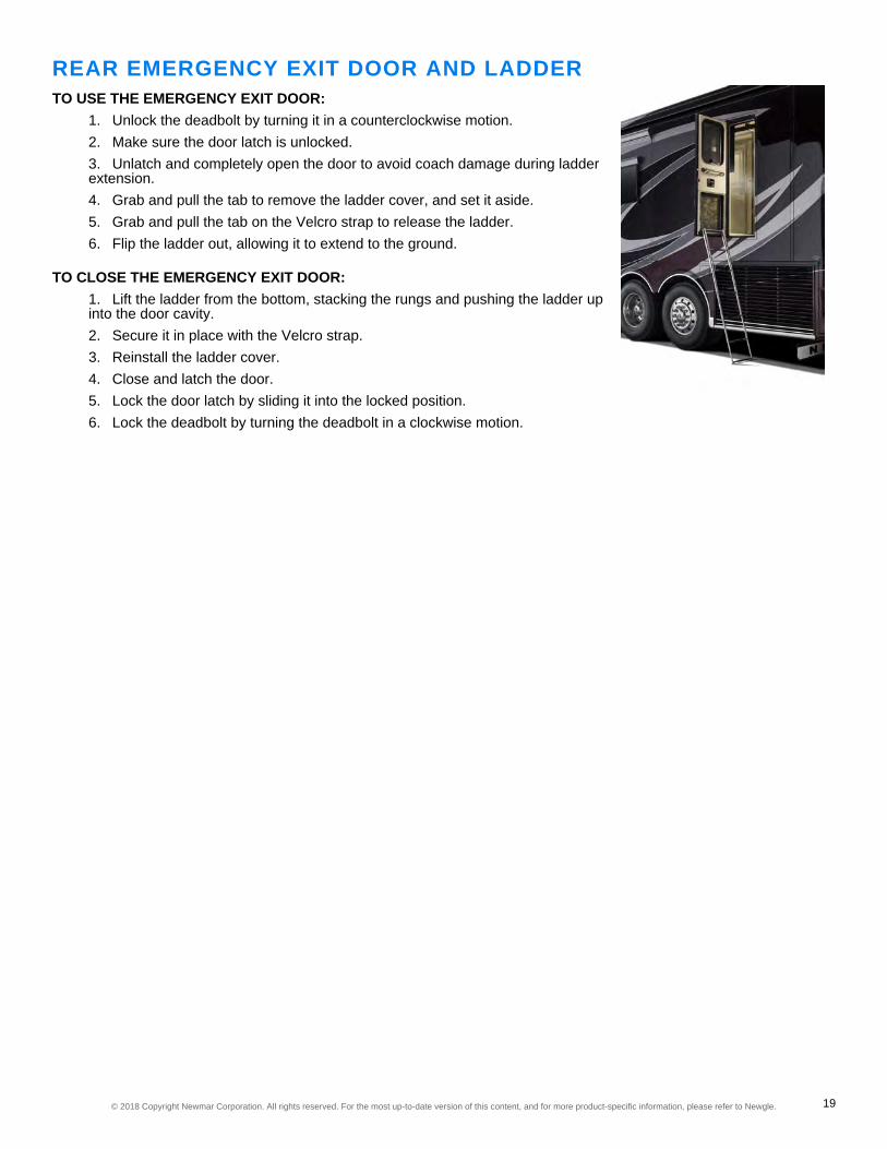
REAR EMERGENCY EXIT DOOR AND LADDERTO USE THE EMERGENCY EXIT DOOR:
1. Unlock the deadbolt by turning it in a counterclockwise motion.2. Make sure the door latch is unlocked.3. Unlatch and completely open the door to avoid coach damage during ladderextension.4. Grab and pull the tab to remove the ladder cover, and set it aside.5. Grab and pull the tab on the Velcro strap to release the ladder.6. Flip the ladder out, allowing it to extend to the ground.
TO CLOSE THE EMERGENCY EXIT DOOR:1. Lift the ladder from the bottom, stacking the rungs and pushing the ladder upinto the door cavity.2. Secure it in place with the Velcro strap.3. Reinstall the ladder cover.4. Close and latch the door.5. Lock the door latch by sliding it into the locked position.6. Lock the deadbolt by turning the deadbolt in a clockwise motion.
© 2018 Copyright Newmar Corporation. All rights reserved. For the most up-to-date version of this content, and for more product-specific information, please refer to Newgle. 19

20© 2018 Copyright Newmar Corporation. All rights reserved. For the most up-to-date version of this content, and for more product-specific information, please refer to Newgle.

APPLIANCESNewmar only uses the most convenient and efficient appliances to make maintaining your coach -and your lifestyle - less of a chore. This category provides detailed information regarding each of theappliances available in your coach, including cooktops and ranges, dishwashers, fireplaces,microwaves and convection ovens, refrigerators, freezers and ice makers, central vacuums,washers and dryers, and water softeners.
Under each sub-category, you will have access to owners manuals, user guides, parts and service manuals, andproduct specifications for each of the appliances available in your Newmar coach (when available from themanufacturer).
IMPORTANTPlease note that all appliances are coach model and year-specific.
APPLIANCE DATA LABEL & INFORMATION SHEETThis sheet contains important information about your coach and can be found in the largest wardrobe in the unit, usuallyeither in the bedroom or bathroom area. The label includes information such as:
1. The Newmar Serial Number (5 or 6 Digits) This number is needed whenever making an appointment forservice or for ordering parts through your Newmar dealer or service center.2. Vehicle Identification Number (VIN): This number is the legal identification of the completed vehicle and is usedby the state for vehicle registration.3. Year - Model - Type - Floorplan4. Manufacturer, Model and Serial Number of factory-installed equipment and components.
IMPORTANTThe manufacturer, model, and serial number of the appliances and accessories installed at the factory in yourunit are listed on this label for convenience. It is important that the label remain in the coach for identificationpurposes. Do not remove or relocate this label.
SAFETY PRECAUTIONSThe following labels relating to the use of your propane or electric appliances may beplaced throughout your coach. Follow all warnings to prevent coach damage, bodilyinjury, or death while operating these types of appliances.
© 2018 Copyright Newmar Corporation. All rights reserved. For the most up-to-date version of this content, and for more product-specific information, please refer to Newgle. 21

INVERTER-POWERED COMPONENTTROUBLESHOOTINGIf your entertainment components or certain appliances arenot working, such as television, DVD player, satellitesystem, refrigerator, or microwave, Newmar recommendschecking the breaker on the inverter, which may be locatedin a compartment or between the chassis frame rails.
COOKTOPS AND RANGESStyle and function meet for a home cooked meal any night of the week, all at your fingertips.Newmar offers several styles and brands of ranges and cooktops for your coach. Whether agourmet or beginner chef, your two or three-burner LP or electric range or cooktop will provide youwith all of the necessities - and wants - you desire and deserve to prepare meals for you and yourfamily.
IMPORTANTThese brief operation instructions are for quick reference only. Any quick start instructions provided shouldnot take the place of the complete Operation Manual provided by this item's manufacturer.
ELECTRIC COOKTOPSIf your coach is equipped with the “All Electric” option, it will feature an electric cooktop in lieu of the standard propanecooktop. Before operating your electric cooktop, make sure the proper AC voltage is being supplied to the cooktop toactivate the burner control to the desired heating level. The associated burner will heat proportionally to the setting. Forinduction cooktops, ferrous metal cookware is required to operate the cooktop.
PROPANE COOKTOPS
WARNINGDo not bring or store propane cylinders, gasoline, or other flammable liquids inside of the vehicle. Failure tocomply could result in fire or explosion.
Your coach may be equipped with a two-burner or three-burner propane cooktop and may feature a manual or electronicspark ignition.
HOW TO OPERATE YOUR PROPANE COOKTOP1. Before operating your propane cooktop, open an overhead vent, turn on an exhaust fan, or open a window.2. To use the cooktop, simply press down and turn the burner control to the correct setting.3. Manually twist the spark igniter or let the electronic ignition spark create a flame.4. The burner controls will vary the flame to your cooking requirements.
© 2018 Copyright Newmar Corporation. All rights reserved. For the most up-to-date version of this content, and for more product-specific information, please refer to Newgle. 22

PROPANE SAFETYThe following labels regarding propane safety arestrategically placed inside of your coach.
PROPANE DISTRIBUTION LINESThe primary gas supply manifold is a black steel piperunning the length of the unit. Most secondary lines leadingto the gas appliances are made of copper tubing with flarefittings. If any of these lines rupture, do not attempt to splicethem. Always run a new line. Gas distribution work must beperformed by an authorized service technician.
THE LP SYSTEM AND CLIMATE CHANGESWhile in high altitudes or extreme cold weather, a gas shortage may be experienced. Running one appliance at a timecan help adjust to this problem.
WARNINGWhen removing or servicing any gas appliance, close the main gas valve on the propane tank to preventdangerous gas leakage that could result in an explosion and possible serious injury. If a gas leak issuspected, have the system inspected and repaired by a qualified service technician as soon as possible.
OUTDOOR COOKING AREAFor coaches equipped with an outdoor cooking area, adhereto all posted warning labels for safe operation.
FOR MORE INFORMATIONRefer to the product manufacturer's owner's manual and links in Newgle to learn more about your coach's cooktop orrange.
© 2018 Copyright Newmar Corporation. All rights reserved. For the most up-to-date version of this content, and for more product-specific information, please refer to Newgle. 23
FIREPLACESThe fireplace provides instant comfort and ambiance to your home away from home. Your fireplaceis a 120 volt electric plug-in fireplace, complete with a thermostat-controlled, fan-forced heater. Thefireplace may be operated using the flame-only function with realistic flames, or turn on or off theheat function, providing you with flames and heat. Some models have an adjustable interior light,flame speed control, and/or a timer setting, and some can even be operated using a remote control.
FOR MORE INFORMATIONRefer to the product manufacturer's owner's manual and links in Newgle to learn more about your coach's fireplace.
MICROWAVES AND CONVECTION OVENSA modern convenience to keep up with even your busiest of travel days. Newmar offers a variety ofmicrowave and convection oven choices to meet your needs and wants to make cooking quick andconvenient. With multiple cooking functions, your microwave allows you to do much more than justwarming up last night's leftovers. With the use of a combination of lights, microwaves, andconvection heat, preparing entire meals is possible in a fraction of the time it takes in a conventionaloven.
All microwaves and convection ovens operate on 120 Volt electricity. The control panel is a touch pad, so entering thetemperature, mode, and cooking time desired is simple. A range hood may be incorporated into the microwave. Themicrowave’s control panel also operates the range hood functions, including the fan and light. The fan has two speeds:low and high.
FOR MORE INFORMATIONRefer to the product manufacturer's owner's manual and links in Newgle to learn more about your coach's microwave orconvection oven, as well as how to use any of its special features.
REFRIGERATORS, FREEZERS, AND ICE MAKERSOffering all of the ingredients you need for a satisfying life on the road. Newmar offers many qualityoptions for your food storage needs, all while blending beautifully with your sleek decor. Withadjustable and removable shelving, your refrigerator and freezer provides you with the flexibility youneed to fit your on-the-road lifestyle. Many models offer the convenience of electronic controls, abuilt in icemaker, and a filtered water dispenser.
Select models allow you to select the incoming power source of your coach, whether AC current or propane gas. Allmodels are equipped with latches to secure the doors for a tight seal to prevent movement during transit.
RESIDENTIAL REFRIGERATORS/FREEZERSResidential-style refrigerators are the most popular option installed in Newmar coaches. The refrigerator operates on120 volt AC power and uses freon and a compressor to keep your food cold and fresh. When placing items on the racksand in the bins, leave enough space for air to flow throughout the entire refrigerator cabinet. For models with a built-inice maker, a pressurized water supply is required. In order for the ice maker to operate, you must have water in the freshtank and have the water pump turned on, or your coach must be connected to city water supply.
ABSORPTION REFRIGERATORS/FREEZERSAbsorption-style refrigerators are another option installed on select coaches. The refrigerator operates on 120 volt ACpower or LP gas and heats a solution in a closed loop system. As the solution changes state and passes through the
© 2018 Copyright Newmar Corporation. All rights reserved. For the most up-to-date version of this content, and for more product-specific information, please refer to Newgle. 24

absorption stage, it cools the inside of the refrigerator and freezer box by extracting the heat and carrying it away in thesolution. It does not use freon and a compressor, so this style of refrigerator takes longer to cool down.It is recommended to pre-chill food and beverages before putting them in the refrigerator and freezer. When placingitems on the racks and in the bins, leave enough space for air to flow throughout the entire refrigerator cabinet. Formodels with a built-in ice maker, a pressurized water supply is required. In order for the ice maker to operate, you musthave water in the fresh tank and have the water pump turned on, or your coach must be connected to city water supply.
EXTERIOR FREEZERSThe installation of a freezer in an exterior storage compartment may be an optional feature on your coach. This freezeroperates on 12 volt and 120 volt electrical power. The freezer is on a slide for easy access for pre-travel packing orcampsite unloading, as well as for easy storage while traveling.
FOR MORE INFORMATIONRefer to the product manufacturer's owner's manual and links in Newgle to learn more about your coach's refrigerator,freezer, and ice maker.
WASHERS AND DRYERSDepending on your model, year, and available options, your coach may be equipped with astackable washer and dryer, or an all-in-one laundry center located in a cabinet. They are built forlife on the road, so they are compact to save space, weight, and resources, without sacrificingperformance. Some coach floorplans may also provide the option for washer and dryer hookups, inlieu of the appliances.
IMPORTANTThese brief operation instructions are for quick reference only. Any quick start instructions provided shouldnot take the place of the complete Operation Manual provided by this item's manufacturer.
OPERATING INSTRUCTIONSThe plumbing and other preparations for the installation of a compact washer and dryer are optional features on yourcoach. The washers and dryers function like those in a home. Most operate on 120 volt electricity; however, somedryers may require 240 volt electricity.
IMPORTANTThe gray tank valve must be in the 'open' position when operating the washing machine.
© 2018 Copyright Newmar Corporation. All rights reserved. For the most up-to-date version of this content, and for more product-specific information, please refer to Newgle. 25

P-TRAPSEach of the sink drains, the shower drain, and the washing machine drain (if equipped) has a water trap to preventholding tank odors from entering the coach. These traps must have water in them in order to trap the odors. Whilestored, the water may evaporate, allowing an odor to enter the coach. If this occurs, run water from the faucet into thedrain, allowing water to fill the trap. Run water into the washing machine. Set the cycle to spin to drain the water to fillthe p-trap.
FOR MORE INFORMATIONRefer to the product manufacturer's owner's manual and links in Newgle to learn more about your coach's washer anddryer.
© 2018 Copyright Newmar Corporation. All rights reserved. For the most up-to-date version of this content, and for more product-specific information, please refer to Newgle. 26

CHASSISFrom the Chassis on up, Newmar coaches are built to be dependable, durable, comfortable, andbeautiful. Built specifically for Newmar with the highest quality in handling, safety, performance, anddependability. This category provides detailed information regarding your axles and tires, as well asthe collision warning, fuel control, leveling and towable braking systems in your coach.
Under each sub-category, you have access to owners manuals, user guides, parts and service manuals, and productspecifications for each aspect of your Newmar chassis.Newmar starts with an innovative chassis weld process to ensure that your coach drives with less noise, a smootherride, and has a longer service life. After the chassis is leveled and squared, it is painstakingly integrated into the rest ofthe structure for strength and integrity. Sub-floor structures are welded to the chassis rail and are insulated for easyclimate control.
FORDThe specific information for your chassis is provided by Ford and covers many topics includinggeneral maintenance, engine information, capacities, tire information, and driver tips.
ROADSIDE ASSISTANCE• Phone: 800.392.3673• Web: http://owner.ford.com/contact-us.html• Mail: Ford Motor Company | Customer Relationship Center | P.O. Box 6248 | Dearborn, MI 48126
FOR MORE INFORMATIONRefer to the product manufacturer's owner's manual and links in Newgle to learn more about your coach's chassis andmaintenance schedule.
IMPORTANTFor all driver-related controls and gauges, lighting, brakes, tires/wheels, and towing information, please referto the Ford Chassis owner's manual.
FUEL SYSTEMSThis section provides information about the fuel systems in your coach, including LP (if equipped),chassis engine fuel, and auxiliary fuel tanks (if equipped).
© 2018 Copyright Newmar Corporation. All rights reserved. For the most up-to-date version of this content, and for more product-specific information, please refer to Newgle. 27

CAUTIONShut off the main gas valve at the tank when thevehicle is not in use.
PROPANE FUEL SYSTEMThe components relating to the propane gas system in yourcoach have been approved for use in recreational vehiclesby a nationally recognized testing laboratory. Propane gasis a clean-burning dependable fuel when properly handled.It is recommended to have the propane system inspectedby an authorized service technician at least once a year andafter every extended trip. This system is tested by both themanufacturer and the dealer; however, leaks may becaused by travel vibrations.
Your coach may be equipped with an ASME (American Society of Mechanical Engineers) approved propane tank. Thistank is controlled with an automatic pressure regulator. The propane tank contains liquid petroleum gas under highpressure. As the fuel is used, the liquid gas vaporizes and passes through the tank valve to a regulator thatautomatically reduces the pressure. The low-pressure gas is then distributed to the appliances throughout the pipemanifold system.
IMPORTANTWhile in high altitudes or extreme cold weather, a gas shortage may be experienced. Running one applianceat a time can help adjust to this problem.
PROPANE TANK FILLINGTank filling should only be performed by trained professionals. Prior to filling the propane tank, turn off all flame or spark-producing appliances, extinguish any smoking items, and turn off the coach engine.
WARNINGInspect the propane fill valve for foreign materials before refueling. Introducing foreign materials into the fillvalve may cause leaking or overfilling. Fire or explosion may be the result of uncontrolled gas flow from anoverfilled tank.
WARNINGDo not fill propane container(s) to more than 80 percent capacity. Overfilling the propane container can resultin uncontrolled propane flow, which can cause fire or explosion. A properly filled container containsapproximately 80 percent of its volume as liquid propane. Failure to comply could result in serious injury ordeath.
WARNINGShut the propane gas valve off when refueling to avoid potential danger from pilot lights igniting fuel fumes.Gas valves on appliances with direct spark ignition (DSI) should also be in the off position. Fire or anexplosion could be the result of ignoring this warning.
© 2018 Copyright Newmar Corporation. All rights reserved. For the most up-to-date version of this content, and for more product-specific information, please refer to Newgle. 28
CHASSIS ENGINE FUEL
IMPORTANTConsult your chassis manufacturer information about your recommended fuel and fuel blends, additives, andmaintenance requirements.
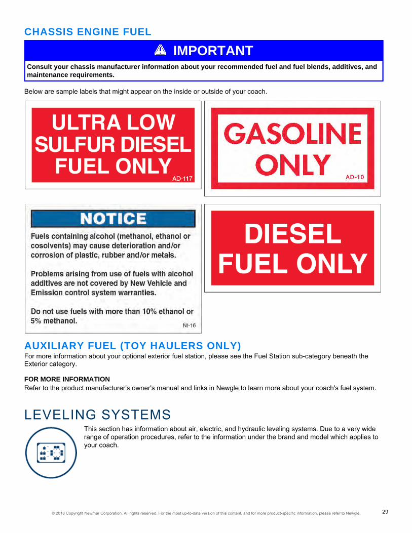
Below are sample labels that might appear on the inside or outside of your coach.
AUXILIARY FUEL (TOY HAULERS ONLY)For more information about your optional exterior fuel station, please see the Fuel Station sub-category beneath theExterior category.
FOR MORE INFORMATIONRefer to the product manufacturer's owner's manual and links in Newgle to learn more about your coach's fuel system.
LEVELING SYSTEMSThis section has information about air, electric, and hydraulic leveling systems. Due to a very widerange of operation procedures, refer to the information under the brand and model which applies toyour coach.
© 2018 Copyright Newmar Corporation. All rights reserved. For the most up-to-date version of this content, and for more product-specific information, please refer to Newgle. 29

IMPORTANTIn the unlikely occasion that the slideout trim hasinadequate clearances, try leveling or repositioningthe coach and rechecking the clearances beforeextending the slideout.
WARNINGDo not lift the wheels off of the ground while leveling the coach. The vehicle may drop and/or move forward orbackward without warning, which may cause serious injury or death.
WARNINGNever attempt to move the unit with the leveling jacks deployed. Always visually inspect the jacks prior tomoving to ensure they are fully retracted, are in the stored position, and the system is turned OFF.
WARNINGBe sure the ground on which you are parked will support the weight of your unit. Often material that seems“safe” to level on will not support the weight at the leveling jack points. Use caution when leveling on hotasphalt, sand, and grass, as the weight of the unit may cause the jacks to sink into the ground. Pads mayneed to be placed under the jacks to spread the weight over a larger area. Always look under your unit prior toleveling to make sure the jacks are clear of debris and other foreign materials that may interfere with leveling.
WARNINGNever operate any leveling system with a person or pet under the unit. Serious injury or death may result!
EXTENDING THE SLIDEOUTS1. Park the coach on a reasonably level campsite.2. Leave the coach at ride-height with air in the air bags (if equipped with airsuspension) or on normal suspension (coaches without air suspension).3. Plug the coach into shore power (if available) or start the generator toincrease the voltage for better slideout operation.4. For a full wall slideout, visually inspect the front vertical trim for adequateclearance. The spacing should look even from top to bottom. (See image.)5. Verify that the path of the slideout is unobstructed and free from anysurrounding objects, both inside and outside of the coach.6. Once the appropriate conditions are met, follow the operating instructionsposted in your coach to extend the slideouts.7. Deploy the leveling jacks.
RETRACTING THE SLIDEOUTS1. Retract the leveling jacks.2. Start the coach.3. Allow the coach air suspension to fill and return to ride height (units without air suspension will return to normalsuspension).4. Turn the engine off.5. For a full wall slideout, visually inspect the front vertical trim for adequate clearance. The spacing should lookeven from top to bottom. (See image for reference.)
© 2018 Copyright Newmar Corporation. All rights reserved. For the most up-to-date version of this content, and for more product-specific information, please refer to Newgle. 30
6. Verify that the path of the slideout is unobstructed and free from any surrounding objects, both inside andoutside of the coach. This includes any water or debris that may have collected on the slideout roof or the topperawning.
IMPORTANTDebris left on the roof or topper may prevent the slideout from sealing properly when retracted, as well asprevent the mechanical lock arms from closing properly when the slideout is extended.
7. Retract the slideouts.8. Inspect all slideouts for complete retraction.9. If the coach is equipped with manual lock arms, make sure to lock them.10. Unplug the coach from shore power when you are ready to depart.
IMPORTANTIn the unlikely occasion that the slideout trim has inadequate clearances, try leveling or repositioning thecoach and rechecking the clearances before retracting the slideout.
CARE AND MAINTENANCE
IMPORTANTThe leveling system should be cycled at least once a month to keep the system in operating condition.
FOR MORE INFORMATIONRefer to the product manufacturer's owner's manual and links in Newgle to learn more about your coach's levelingsystem.
EQUALIZER LEVELING SYSTEMS1"Since its introduction, Equalizer's Auto-Level has quickly become the premium choice in leveling systems. Utilizing
four two-way hydraulic cylinders, Auto-Level has the ability to extend and retract the legs during the leveling sequence.The automatic, one touch operation levels a vehicle in less than two minutes, operating each leg independently in asequential process."This sequential leveling is a patented process that provides a more precise level throughout the length of the vehicle,adding stability to the vehicle while leveling it as low to the ground as possible. It's quick, easy and on the level!
WARNINGRead the Operation Manual for your specific leveling system, and follow all safety warnings and notices.
IMPORTANTThese brief operation instructions are for quick reference only. Any quick start instructions provided shouldnot take the place of the complete Operation Manual provided by this item's manufacturer.
2AUTO-LEVEL OPERATION
© 2018 Copyright Newmar Corporation. All rights reserved. For the most up-to-date version of this content, and for more product-specific information, please refer to Newgle. 31

POWER ONPress and release the POWER button to engage power. All LED’s on the panel will come on then most will go out. TheLED next to the POWER button should be lit RED when power is on.
EXTENDTo extend the jacks the ignition key must be in the engine run or on position and the park brake must be applied. Toretract the ignition key must be in the engine run or on position. If you attempt Auto-Level or All Retract you will hear a“deni” tone if the key or park brake is in the improper position.
AUTO-LEVELPress the AUTO-LEVEL button and release. The system will send out a continuous series of beeps, the ‘OPERATING’LED will be on RED to let you know AUTO-LEVEL is operating and will automatically level the coach. When completed,the keypad will signal a successful level with a dual-level tone. Press and release the POWER button.
NOTICEThe keypad may be left on once level has been achieved. The keypad will enter 'sleep mode' after five minutesof inactivity.
IMPORTANTThe jacks down LED lights must be off for Auto-Level to function. If needed, press the ALL RETRACT buttonto clear and then Auto-Level should function.
3RETRACTING THE JACKSHELPFUL HINT: If your coach is equipped with air suspension, it is recommended that the coach be started andchassis air pressure allowed to build before pressing ALL RETRACT. This will ensure adequate air supply to the chassisair valves.To retract all jacks simultaneously, press and release the All RETRACT button. All jacks will automatically retract andreturn to stowed position. The pump will run in retract mode until all of the jacks are fully stowed (plus an additional 5seconds) up to a maximum of 60 or 90 seconds). This is the proper method for retracting the jacks prior to travel.You may stop the ALL RETRACT by pressing any button on the keypad. Jacks may be retracted in pairs by using theUP▲ button for each end or side for leveling purposes however the ALL RETRACT must be used to fully stow the jacksprior to travel.The jacks down LED’s will turn off, indicating the jacks are in the “stowed” position.
POWER OFFPress and release the Power keypad button.
IMPORTANTVisually confirm all jacks are retracted prior to travel.
MANUAL OPERATIONPOWER ONPress and release the POWER keypad button to engage power. All LED’s will come on then most will go out. The LEDnext to the POWER button should be lit RED when power is on.
EXTENDING JACKS MANUALLYTo extend the jacks the ignition key must be in the engine run or on position and the park brake must be applied. If youattempt to extend or retract jacks by pressing the DOWN▼ or UP▲ keypad buttons you will hear a “deny” tone from thekeypad if the ignition key and or park brake is in the improper position.
© 2018 Copyright Newmar Corporation. All rights reserved. For the most up-to-date version of this content, and for more product-specific information, please refer to Newgle. 32

PLANTING THE JACKSThe jacks will be extended in pairs Fronts or Rears or Left or Right Using the DOWN▼ (extend) keypad buttons, extendthe jacks until they contact the ground (this is referred to as “planting” the jacks). As you extend each pair of jacks thecorresponding LED jack status lights will come on to indicate jack(s) are out of the “stowed” position.
NOTICEJacks will be operated in pairs.
Extend and plant the front jacks first. Then extend and plant the rear jacks. Only after planting the fronts and then therears, should side to side corrections (leveling) be attempted. This process will stabilize all four corners and minimizetwist prior to the leveling process.
WARNINGDo not manually over extend jacks. This may cause unwanted stress on the coach or the jacks.
LEVELING THE COACHUse a bubble level on a flat surface in the center of the coach as a reference. Level the vehicle by using DOWN▼(extend) or UP▲ (retract) keypad buttons until the vehicle is level. Front to rear then side to side.
WARNINGDo not attempt to lift the vehicle tires off of the ground. Only lift (extend) enough to level and stabilize the unit.
Once level, press and release the POWER button to turn off the keypad.
NOTICEThe keypad may be left on once level has been achieved. The keypad will enter 'sleep mode' after five minutesof inactivity.
RETRACTING THE JACKSHELPFUL HINT: If your coach is equipped with air suspension, it is recommended that the coach be started andchassis air pressure allowed to build before pressing ALL RETRACT. This will ensure adequate air supply to the chassisair valves.To retract the jacks the key must be in the engine run or on position and the park brake must be applied. To retract alljacks simultaneously, press and release the ALL RETRACT button. All jacks will automatically retract and return tostowed position. The pump will run in retract mode until all of the jacks are fully stowed (plus an additional 5 seconds- upto a maximum of 60 or 90 seconds). This is the proper method for retracting the jacks prior to travel.You may stop the ALL RETRACT by pressing any button on the keypad. Jacks may be retracted in pairs by using theUP▲ button for each end or side for leveling purposes. However, the ALL RETRACT must be used to fully stow thejacks prior to travel. The jacks down status LED lights will turn off, indicating the jacks are in the stowed position.
POWER OFFPress and release the POWER keypad button.
IMPORTANTVisually confirm all jacks are retracted prior to travel.
© 2018 Copyright Newmar Corporation. All rights reserved. For the most up-to-date version of this content, and for more product-specific information, please refer to Newgle. 33

FLUID LEVEL MAINTENANCEThe hydraulic leveling system was filled with Dexron/Mercon transmission fluid during production. Periodically check thefluid levels in the leveling system. The reservoir level should remain at 3/4 full when the jacks are retracted. Add fluid asneeded. Change the fluid if debris or water enters the reservoir.1 Material sourced from Equalizer Systems for Motorhomes2 Material sourced from Equalizer Systems Auto-Level NEWMAR Operation and Warranty Guide as preparedspecifically for NEWMAR owners by Equalizer Systems: Effective 2011, Revision 2014 (pertaining to Systems UsingPump #3043 & Controller #3055)3 Material sourced from Newmar Auto-Level Operation Manual
WHEELS AND TIRESNewmar's quality extends to every inch of your coach, right down to the tires and wheels. Thedurability and longevity of your tires will provide you with the confidence and peace of mind youneed to relax and enjoy the ride. This sub-category will provide you with information regarding thetire construction and size, inflation and pressure guidelines, as well as the proper use and care ofyour coach-specific tires and wheels.
WARNINGProper tire maintenance is critical to the safety, operation, and durability of your coach. Failure to follow andmonitor tire pressure guidelines may result in premature tire failure.
The primary areas of concern are the tire size, inflation, and operational information. The sidewall of the tire containsdetailed information about the construction, inflation, and carrying capacity of the tire. Become familiar with thisinformation, and operate the vehicle within the capacity parameters outlined.
TIRE SIZEThe sidewall of the tire contains information that is important toknow to ensure proper use of the tire, as well as to maintain longlife. Take the time to become familiar with the size, load rating, andpressure information listed on the sidewalls of the tires.This tire size is 315 / 80 R 22.5. From this size, we can determinethe physical dimensions of the tire, as well as its basicconstruction. The tire size breaks down like this:
• The first number, “315”, is the section width of the tire inmillimeters. The section width is the measurement of the tirefrom the outside sidewall to the inside sidewall.• The second number is the height of the sidewall, expressedas a percentage of the section width. In this case, the numberis “80”, so the sidewall height accounts for 80 percent of thetire's section width.• The “R” in the tire size indicates that this tire is “radial” inconstruction. The belts are wrapped around the tire in a radialdesign, from bead to bead.• The final number is “22.5”, which is the rim size the tire wasdesigned to fit. This tire fits a 22.5” diameter wheel.
© 2018 Copyright Newmar Corporation. All rights reserved. For the most up-to-date version of this content, and for more product-specific information, please refer to Newgle. 34

Example of a Tire Inflation Chart
TIRE CARE AND MAINTENANCETo ensure your tires are operating safely, regularlyinspecting your tires and checking your tire pressure isabsolutely mandatory.Tire pressures should be checked and adjusted before andafter each trip. Always check and adjust the pressures whilethe tires are cold. Never add or release pressure from thetires when they are hot (after having driven a mile or more).For safe operation and maximum weight carrying capacity,it is imperative that the tires be inflated to and maintained atthe listed tire pressures on the Federal ID Tag. This tag isaffixed to the interior wall just behind the driver’s seat inyour coach.
WARNINGFailure to follow proper inflation guidelines may result in tire failure, which can cause loss of vehicle controlor accidents resulting in property damage, bodily injury, or death.
IMPORTANTThe tire pressure settings can change depending on whether they are used in single or dual tire situations.
IMPORTANTMake sure the tire pressures are the same across an axle, while never exceeding the maximum air pressurelimit stamped on the wheels or tires, or leaving a tire below the minimum pressure listed on your tire inflationchart.
If you are operating your coach while staying significantly under the maximum weight carrying capacity, you mayexperience an unnecessarily firm ride. To correct this condition, it is recommended for you to weigh the coach when it isfully loaded as you would travel, with full fuel, water, and LP tanks, all travelers, and your belongings, as well as anytowed equipment. Weigh each axle end separately, and use the heaviest end weight to determine the axle's coldinflation tire pressure.
Use the inflation chart provided by your specific tiremanufacturer according to brand, series, size, and loadrange. Also, pay attention to the chart when referring to dualor single tire configurations, as they will change based uponwhich tire you are inflating.
IMPORTANTDo not use the example to find your recommended tire pressures. Refer to your tire manufacturer's owner'smanual and specific tire inflation guidelines.
NOTICEExact tire inflation charts will not be provided by Newmar. Each tire manufacturer provides this information,as it changes by brand, make, tire series, tire size, as well as if it is used in a single or dual setup. For moreinformation about your tires and the inflation specifications, please refer to the Item Home Page of your tiremanufacturer.
© 2018 Copyright Newmar Corporation. All rights reserved. For the most up-to-date version of this content, and for more product-specific information, please refer to Newgle. 35

FOR MORE INFORMATIONRefer to the product manufacturer's owner's manual and links in Newgle, as well as the "Tire Inflation PressureTechnical Information" article, to learn more about your coach's wheels and tires.
© 2018 Copyright Newmar Corporation. All rights reserved. For the most up-to-date version of this content, and for more product-specific information, please refer to Newgle. 36
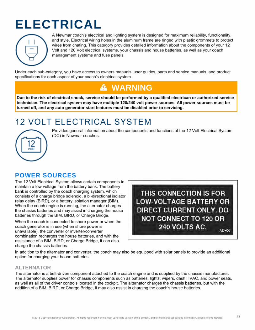
ELECTRICALA Newmar coach's electrical and lighting system is designed for maximum reliability, functionality,and style. Electrical wiring holes in the aluminum frame are ringed with plastic grommets to protectwires from chafing. This category provides detailed information about the components of your 12Volt and 120 Volt electrical systems, your chassis and house batteries, as well as your coachmanagement systems and fuse panels.
Under each sub-category, you have access to owners manuals, user guides, parts and service manuals, and productspecifications for each aspect of your coach's electrical system.
WARNINGDue to the risk of electrical shock, service should be performed by a qualified electrican or authorized servicetechnician. The electrical system may have multiple 120/240 volt power sources. All power sources must beturned off, and any auto generator start features must be disabled prior to servicing.
12 VOLT ELECTRICAL SYSTEMProvides general information about the components and functions of the 12 Volt Electrical System(DC) in Newmar coaches.
POWER SOURCESThe 12 Volt Electrical System allows certain components tomaintain a low voltage from the battery bank. The batterybank is controlled by the coach charging system, whichconsists of a charge bridge solenoid, a bi-directional isolatorrelay delay (BIRD), or a battery isolation manager (BIM).When the coach engine is running, the alternator chargesthe chassis batteries and may assist in charging the housebatteries through the BIM, BIRD, or Charge Bridge.When the coach is connected to shore power or when thecoach generator is in use (when shore power isunavailable), the converter or inverter/convertercombination recharges the house batteries, and with theassistance of a BIM, BIRD, or Charge Bridge, it can alsocharge the chassis batteries.In addition to the alternator and converter, the coach may also be equipped with solar panels to provide an additionaloption for charging your house batteries.
ALTERNATORThe alternator is a belt-driven component attached to the coach engine and is supplied by the chassis manufacturer.The alternator supplies power for chassis components such as batteries, lights, wipers, dash HVAC, and power seats,as well as all of the driver controls located in the cockpit. The alternator charges the chassis batteries, but with theaddition of a BIM, BIRD, or Charge Bridge, it may also assist in charging the coach's house batteries.
© 2018 Copyright Newmar Corporation. All rights reserved. For the most up-to-date version of this content, and for more product-specific information, please refer to Newgle. 37

GENERATORWhen shore power is unavailable, the generator takes mechanical energy and converts it into alternating current tosupply 120 volts to the coach and charge the coach's house via the converter or inverter/converter and the chassisbatteries via BIRD, BIM, or charge bridge.The generator is typically located in the front of the unit between the frame rails on diesel coaches. On gas units, thegenerator may be located anywhere between the mid and rear section of the coach. Generators can be powered by gas,liquid propane, or diesel fuel.
CONVERTER AND INVERTER/CONVERTER COMBINATIONAll Newmar coaches are equipped with a converter or inverter/converter combination. A converter transforms alternatingcurrent or shore line power 120 Volts to low-voltage direct current to provide power to the coach's 12 Volt house andchassis batteries. On the other hand, an inverter transforms direct current to alternating current to provide power tospecified appliances and entertainment systems.
SOLAR PANELSome Newmar units are equipped with a 10 Watt solar panel wired to the chassis batteries. Prior models may have afive or 10 Watt solar panel and may be wired to the chassis-side KIB panel.
BATTERIESPlease refer to the Battery Basics article for more information.
POWER DISTRIBUTIONBATTERY DISCONNECTNewmar uses an Intellitec disconnect relay connected to the batterybank to disconnect certain loads when placing the coach in storage.Keep in mind that not all loads are disconnected. This is veryimportant to remember when a coach is put into storage and is notplugged into shore power. Before placing the battery disconnect inthe "off" position, make sure the inverter (if equipped) is turned off.When an older coach is stored while plugged into shore power, donot use the battery disconnect. If the battery disconnect is used, thechassis batteries will not receive a charge from the converter orinverter/converter combination. This is due to the coach battery wirebeing disconnected, meaning the BIM or the BIRD will not engage.The Bay Star Sport has a manual rotary key switch to disconnectpower, which is located in the overhead above the entry door. Fifthwheel products also used a manual rotary disconnect switch, whichwere normally located in the bathroom. All other coaches have asingle lighted switch located in the front overhead that turns off thehouse voltage.
IMPORTANTWhen the battery disconnect is 'off', meaning you have disconnected components from the batteries, thereare still some loads on the batteries connected to the hot side of the Battery Disconnect Relay. Some of theseloads may be Radio Memory, Entry Steps, and LP Detector. These will draw from the batteries, even when thedisconnect is 'off'. Pull the fuse for each of the 'HOT' circuits to stop the batteries from being drained.
To learn more, visit the Battery Disconnect home page in Newgle.
© 2018 Copyright Newmar Corporation. All rights reserved. For the most up-to-date version of this content, and for more product-specific information, please refer to Newgle. 38

BI-DIRECTIONAL ISOLATOR RELAY DELAY (BIRD)Current gas coaches with 30 Amp electrical service, as well as someolder diesel coaches, use an Intellitec Bi-Directional Isolator RelayDelay (BIRD) with a separate solenoid. The BIRD monitors both thechassis and house battery and is the only place in the coach wherethey both merge. The BIRD only functions when the engine orgenerator is running or when the coach is connected to shore power.To learn more, visit the Bi-Directional Isolator Relay Delay homepage in Newgle.
BATTERY ISOLATION MANAGER (BIM)All current Dutch Star, Ventana, and Ventana LE diesel coaches, aswell as gas coaches with 50 Amp electrical service, use a PrecisionCircuits all-in-one Battery Isolation Manager (BIM). The BIM monitorsboth the chassis and house battery and is the only place in the coachwhere they both merge. The BIM only functions when the engine orgenerator is running or when the coach is connected to shore power.To learn more, visit the Battery Isolation Manager home page inNewgle.
CHARGE BRIDGE SOLENOIDAll current model New Aire, Mountain Aire, London Aire, Essex, andKing Aire coaches use Silverleaf, a computerized coachmanagement system.One of its many functions is to control the battery charging throughthe Charge Bridge Solenoid. The TM102 module monitors thebattery state and senses the house and chassis battery voltage.When the parameters are met, the TM102 module activates thesolenoid, causing it to bridge or connect the chassis and housebattery banks.For more information on your coach's TM102 module, refer to theSilverLeaf Functional Guide in Newgle.
© 2018 Copyright Newmar Corporation. All rights reserved. For the most up-to-date version of this content, and for more product-specific information, please refer to Newgle. 39

FUSE BLOCKS AND MINI-BREAKERSWhen a 12 Volt wire is ran, most of the circuits are protected with fuses or mini-breakers. These can be located atvarious areas in the coach but are typically located near the main breaker panel. The following photos are examplesonly. However, they may also be found in areas such as:
INTERIOR• Rear bedroom• Rear bathroom• Closet
EXTERIOR• Power cord compartment• Left, front electrical compartment(located beneath the driver window)• Front firewall (gas coaches)
There are also some circuits that areprotected with an inline fuse. Some fuseblocks have fixed relays integrated on aboard. The board below is located in thecord compartment.
BASIC 12 VOLT POWER FLOWSince a battery is only an electrical storage component, 120Volt power must be present to charge the batteries from theconverter or inverter/converter combination unit. It isnecessary to have 12 Volt power supplied from the coach'shouse battery bank in order to operate the interior lights andother 12 Volt loads such as slideout control systems, waterpumps, vent fans, monitoring systems, etc.Most of this power flows through the battery disconnect tothe fuse block or mini-breakers, which prevents overloadingthe circuit prior to progressing to the 12 Volt load. There aresome 12 Volt circuits that do not go through the housebattery disconnect; however, these loads still pass througha fuse or mini-breaker before progressing to the load.
IMPORTANTWhen a 12 Volt load or component is not working, both 12 Volt power (+) and 12 Volt ground (-) are needed forthe load to complete the 12 Volt circuit.
© 2018 Copyright Newmar Corporation. All rights reserved. For the most up-to-date version of this content, and for more product-specific information, please refer to Newgle. 40
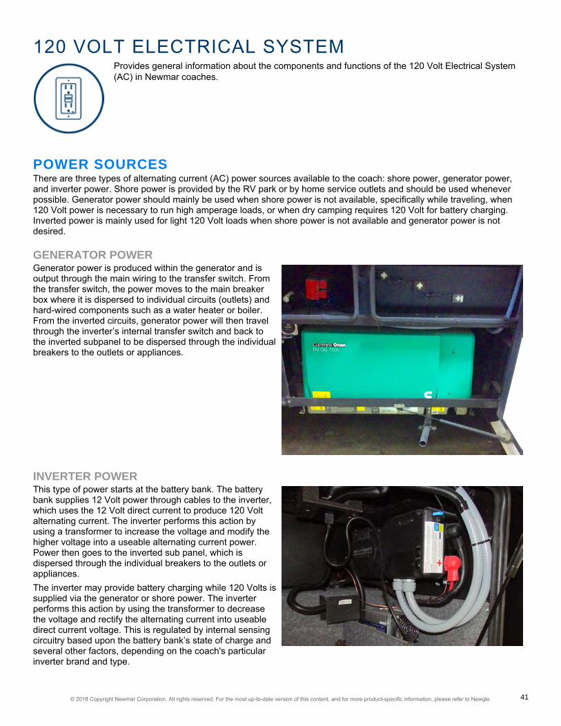
120 VOLT ELECTRICAL SYSTEMProvides general information about the components and functions of the 120 Volt Electrical System(AC) in Newmar coaches.
POWER SOURCESThere are three types of alternating current (AC) power sources available to the coach: shore power, generator power,and inverter power. Shore power is provided by the RV park or by home service outlets and should be used wheneverpossible. Generator power should mainly be used when shore power is not available, specifically while traveling, when120 Volt power is necessary to run high amperage loads, or when dry camping requires 120 Volt for battery charging.Inverted power is mainly used for light 120 Volt loads when shore power is not available and generator power is notdesired.
GENERATOR POWERGenerator power is produced within the generator and isoutput through the main wiring to the transfer switch. Fromthe transfer switch, the power moves to the main breakerbox where it is dispersed to individual circuits (outlets) andhard-wired components such as a water heater or boiler.From the inverted circuits, generator power will then travelthrough the inverter’s internal transfer switch and back tothe inverted subpanel to be dispersed through the individualbreakers to the outlets or appliances.
INVERTER POWERThis type of power starts at the battery bank. The batterybank supplies 12 Volt power through cables to the inverter,which uses the 12 Volt direct current to produce 120 Voltalternating current. The inverter performs this action byusing a transformer to increase the voltage and modify thehigher voltage into a useable alternating current power.Power then goes to the inverted sub panel, which isdispersed through the individual breakers to the outlets orappliances.The inverter may provide battery charging while 120 Volts issupplied via the generator or shore power. The inverterperforms this action by using the transformer to decreasethe voltage and rectify the alternating current into useabledirect current voltage. This is regulated by internal sensingcircuitry based upon the battery bank’s state of charge andseveral other factors, depending on the coach's particularinverter brand and type.
© 2018 Copyright Newmar Corporation. All rights reserved. For the most up-to-date version of this content, and for more product-specific information, please refer to Newgle. 41

50 amp to 30 amp adapter
30 amp to 20 amp adapter
50 amp to 20 amp adapter
SHORE POWERMost RV parks provide 30 Amp, 120 Volt at the site; however, manyparks also provide 50 Amp, 240 Volt service to accommodate theelectrical needs of newer and larger coaches. Shore power is suppliedto the coach via a power cord. Two sizes of power cords are found inNewmar coaches: 50 Amp and 30 Amp. The 50 Amp cords are madeup of four conductors #8 stranded wire and a molded plug. The 30Amp cords are made up of three conductors #10 stranded wire and amolded plug.Shore power enters through the 30 or 50 Amp power cord to thepower cord reel (if equipped). From the power cord reel, it travels tothe transfer switch and then to the main breaker box where it isdispersed to the individual circuits to supply power to hard-wiredcomponents such as air conditioners, water heaters, etc. and then tothe inverter (if equipped).The inverted circuits move from the inverter's internal transfer switchto the inverter subpanel (a smaller breaker box). From the subpanel,the power circulates to the individual breakers and to the electricaloutlets and appliances.
SHORE POWER ADAPTERS
IMPORTANTNewmar Corporation does not recommend use of adapter, cheater, or dog-bone style connectors that willmodify the existing shore power cord to a different style of outlet. Use of this type of adapter will greatlyreduce the amount of available current in the unit, as well as create the potential for electrical failure and/orfire.
If an adapter is used, there are three common sizes ofpower cord adapters available to adjust to a smalleramperage outlet:
1. 30 amp to 20 amp2. 50 amp to 20 amp3. 50 amp to 30 amp
It is important to understand the risks involved and the possible effects of using adapters in conjunction with your coach.Some of these risks and possible effects include:
• Melted or damaged adapters causing poor connection (or no connection at all)• Melted or damaged 30 or 50 Amp plugs causing fluctuations in voltage that may damage electronics• Insufficient amperage causing the tripping of a breaker at the post or a limited use of appliances
© 2018 Copyright Newmar Corporation. All rights reserved. For the most up-to-date version of this content, and for more product-specific information, please refer to Newgle. 42
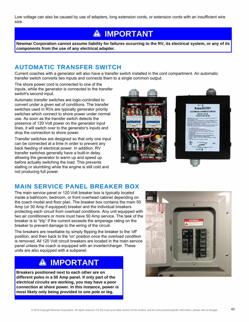
IMPORTANTBreakers positioned next to each other are ondifferent poles in a 50 Amp panel. If only part of theelectrical circuits are working, you may have a poorconnection at shore power. In this instance, power ismost likely only being provided to one pole or leg.
Low voltage can also be caused by use of adapters, long extension cords, or extension cords with an insufficient wiresize.
IMPORTANTNewmar Corporation cannot assume liability for failures occurring to the RV, its electrical system, or any of itscomponents from the use of any electrical adapter.
AUTOMATIC TRANSFER SWITCHCurrent coaches with a generator will also have a transfer switch installed in the cord compartment. An automatictransfer switch converts two inputs and connects them to a single common output.The shore power cord is connected to one of theinputs, while the generator is connected to the transferswitch's second input.Automatic transfer switches are logic-controlled toconvert under a given set of conditions. The transferswitches used in RVs are typically generator priorityswitches which connect to shore power under normaluse. As soon as the transfer switch detects thepresence of 120 Volt power on the generator inputlines, it will switch over to the generator's inputs anddrop the connection to shore power.Transfer switches are designed so that only one inputcan be connected at a time in order to prevent anyback feeding of electrical power. In addition, RVtransfer switches generally have a built-in delayallowing the generator to warm up and speed upbefore actually switching the load. This preventsstalling or stumbling while the engine is still cold andnot producing full power.
MAIN SERVICE PANEL BREAKER BOXThe main service panel or 120 Volt breaker box is typically locatedinside a bathroom, bedroom, or front overhead cabinet depending onthe coach model and floor plan. The breaker box contains the main 50Amp (or 30 Amp if equipped) breaker and the individual breakersprotecting each circuit from overload conditions. Any unit equipped withtwo air conditioners or more must have 50 Amp service. The task of thebreaker is to “trip” if the current exceeds the amperage rating on thebreaker to prevent damage to the wiring of the circuit.The breakers are resettable by simply flipping the breaker to the 'off'position, and then back to the 'on' position once the overload conditionis removed. All 120 Volt circuit breakers are located in the main servicepanel unless the coach is equipped with an inverter/charger. Theseunits are also equipped with a subpanel.
© 2018 Copyright Newmar Corporation. All rights reserved. For the most up-to-date version of this content, and for more product-specific information, please refer to Newgle. 43

IMPORTANTThis function must be enabled in order for the AGS tofunction properly.
SUBPANELThe subpanel is a smaller 120 Volt breaker box containing the breakers for the circuitswhich the inverter is wired to power. It is typically located near the main breaker boxunless the coach is equipped with an Energy Management System (EMS). In this case,the subpanel is often located within the EMS panel. The subpanel is installed to limit theAC power use to specific circuits when the electricity is supplied by the inverter. Someinverters may be used to power a specific circuit. In this case, a subpanel is not used.
AUTOMATIC GENERATOR START (AGS)On units equipped with AGS, the generator will start andprovide 120 Volt power if the incoming shore power voltageis not present and startup parameters are met.
50 AMP ENERGY MANAGEMENT SYSTEM (EMS)The 50 Amp Precision Circuits Energy Management Systemis currently offered as standard equipment on all CanyonStar, Ventana, and Dutch Star coaches. Its function is toprovide power management for certain 120 Volt loads andas a system of energy management to minimize theoverloading and tripping of circuit breakers. The EMScontains a main distribution panel with a self-containedcontrol module and a remote display panel, which istypically located in the dash overhead electrical controlcabinet.The EMS control module automatically senses the availablepower being supplied to the coach. The module determineswhether it is connected to a 50 Amp (240 Volt) or thegenerator. On 120 Volt service, it is unable to determine ifthe source is providing 30, 20 or 15 Amp shore power.Depending on available power, it can control up to seven loads.
© 2018 Copyright Newmar Corporation. All rights reserved. For the most up-to-date version of this content, and for more product-specific information, please refer to Newgle. 44

The EMS controls air conditioner loads using low-voltage switching and other 120 Volt, heavy-load appliances, such asblock heaters, water heating elements, and air conditioners. The EMS will also control the 2012 Magnum inverter chargerate or switch to invert depending on the charging status. The charger will only reduce once it is in float status.The current-sensing relay will display the amperage on each leg. The EMS will start shedding loads and look at the ACcurrent when it sheds a load, determining when it has enough current available to turn on the load again.When the EMS sheds a load, it only looks at one leg to see how much of a load was shed. For coaches equipped withthe SilverLeaf system, refer to the SilverLeaf Functional Guide for more information on your EMS.
CONVERTERSAll Newmar coaches are equipped with a converter or aninverter/converter combination. Converters are used totransform alternating current power (120 Volt AC) to directcurrent power (12 Volt DC). Converters supply the coachwith 12 Volt power to operate systems in the coach andprovide battery charging.Newmar currently uses three sizes of converters: 45, 60,and 80 Amp models. Previous units may have a 55 or 75Amp converter or two 45 Amp converters with a total of 90Amps available. When replacing a converter, it is necessaryto use the same size converter to ensure sufficient wiringand breakers for the converter's input and output ratings.Possible causes of converter failure:
• Overheating caused by cooling fan malfunction orinadequate ventilation causing damage to the converter• Blown fuses
INVERTERSAn inverter changes 12 Volt DC power to 120 Volt ACpower. Coaches with an inverter only typically use it forpowering the entertainment equipment like the TV, DVD,and Blu-ray players. The inverters used for this purpose areusually 600 watt to 1000 watt (1000 Watt inverters may alsopower a small refrigerator) and do not have battery chargingcapability.The inverters are usually located in a basementcompartment of the coach. Some inverters have a remotepanel for an on/off switch in the overhead driver area orabove the entry door. When power is supplied by either thegenerator or shore power, the inverter merely allows thepower to "pass through" and will then stop pulling powerfrom the batteries to try and supply 120 Volt power. There isa protective breaker on the inverter to prevent circuitoverload.Possible causes for inverter failure:
• Overheating caused by inadequate ventilation causing damage to the inverter• Overloading the circuit causing "tripped" breakers
© 2018 Copyright Newmar Corporation. All rights reserved. For the most up-to-date version of this content, and for more product-specific information, please refer to Newgle. 45

INVERTER/CONVERTER COMBINATIONSMany Newmar coaches are equipped with inverter/charger combinationunits, sometimes referred to as an inverter/converter unit. These unitsrange from 1200 to 3000 Watt and serve as a three stage charger and aninverter. Coaches equipped with this option will also be equipped with a120 Volt subpanel.The subpanel is used to limit the circuits powered by the inverter(s). This isnecessary to avoid draining the batteries by supplying inverted power to allcircuits. The subpanel is located next to the main service panel. On unitsequipped with an EMS, the subpanel is located in the same breaker boxbut is separated in the interior of main panel. The coach battery banksupplies the inverter 12 Volt power and has a high amp fuse link on thepositive lead from the batteries and is located near the battery bank.The inverter/charger can be controlled by a remote panel, from anothersystem like SilverLeaf, or at the inverter itself. The remote panel is typicallylocated in the front overhead compartment or above the entry door and isused to control the inverter and the battery charging functions. If a remotepanel is connected to the inverter, then the remote panel takes priority.
THREE-STAGE CHARGING PROCESSThe charging cycle uses three states: bulk, absorption, and float. During the initial bulk stage, the inverter charges atnear its full current ability. This causing the battery voltage to rise over time. After the battery voltage reaches the bulkvoltage setting, the charger starts the absorption stage.During this phase, the charge rate is gradually reduced while the battery voltage is held near the bulk voltage setting.This insures that the battery is fully charged. The float stage is initiated when the battery has been held at the bulkvoltage setting for the absorption period. At this point the battery voltage is allowed to fall to the float voltage setting,where it is maintained until another charge cycle is initiated. This reduces gassing of the battery and keeps it fullycharged. A new three stage charging cycle is initiated after an AC source is reapplied to the AC input terminals.
GROUND FAULT CIRCUIT INTERRUPT (GFCI) OUTLETSThe Ground Fault Circuit Interrupt (GFCI) outlets protect the user from ground faultsbetween a hot wire and ground. The 120 Volt electrical outlets in the kitchen and batharea are GFCI protected receptacles. The electrical outlets located in the Slideouts arewired through the kitchen GFCI. The exterior electrical outlets are wired through thebathroom GFCI. On units equipped with the floor heat option, a separate GFCI isinstalled in the bathroom or near the main breaker box. Units with the holding tank heatpad option will have an additional GFCI located in the basement area; however, theexact location varies.The GFCI outlets should be tested at least once a month. The 120 Volt electricalsystem must be energized in order to test the GFCI. The reset button needs to bepressed before starting the test. Then push the test button, which will cause the resetbutton to pop out, confirming the protected circuits have been disconnected. Push thereset button again until a click is heard to reactivate the protected circuit. If the GFCI isworking properly, the reset button will remain in the “IN” position. If an item plugged intoa Slideout or outside receptacle is not working, check for a tripped GFCI in the kitchenor bathroom. Likewise, if the floor heat or holding tank heat pads are not working, checkthe GFCI for that circuit.
WARNINGThe GFCI will not reduce the shock hazard if the short is between a neutral and hot wire or two hot load wires.
© 2018 Copyright Newmar Corporation. All rights reserved. For the most up-to-date version of this content, and for more product-specific information, please refer to Newgle. 46

IMPORTANTDo not use an adapter, cheater, or extension cord thatbreaks the continuity of the ground circuit to theground pin. Never remove the ground pin from a plugin order to connect it to a two-pronged ungroundedoutlet.
House Battery Bank Example
120 VOLT OUTLETSSeveral 120 volt receptacles are located throughout the interior of the unit. Thesereceptacles require three-pin plugs that provide proper grounding to protect you fromelectrical shock. The breaker for the outlets are usually located in the breaker box. Ifthe breakers are on the inverted circuitry, they will be located in the subpanel near themain breaker box.
BATTERIESProvides information about the house and chassis battery banks, battery inspection and care, aswell as battery replacement.
HOUSE AND CHASSIS BATTERY BANKSThere are two different battery banks in a Newmar coach:House and Chassis.The House Battery Bank is necessary to operate everythinga customer may require in order to live in the unit. Thesebatteries can be either 6 Volt deep cycle (all diesel coaches)or 12 Volt deep cycle, depending on the model and brand ofthe coach. Newmar house batteries may be serviceable orsealed.
© 2018 Copyright Newmar Corporation. All rights reserved. For the most up-to-date version of this content, and for more product-specific information, please refer to Newgle. 47

Chassis Battery Bank Example
The Chassis Battery Bank supplies power to everything acustomer requires to drive the unit. Currently, Newmar'schassis batteries are all Liquid Lead Acid. Spartan and Fordchassis have serviceable batteries and Freightliner chassisbatteries are sealed. The type and brand of chassis batterymay vary depending on coach year, make, and model.Chassis batteries may need to be disconnected andremoved from the coach to maintain proper electrolytelevels or perform routine battery maintenance. Housebatteries may be either serviceable Liquid Lead Acid/Flooded or AGM/Sealed Cell.The chassis batteries on your motorhome are installed andwarranted by the chassis manufacturer. The coach (orhouse) batteries on your motorhome are installed byNewmar Corporation, but warranted by the batterymanufacturer. These batteries are used to operate the 12volt items that are not a direct part of the chassis.Depending on the coach, the batteries may be located inthe front of the coach under the front cap or on a pull outtray in an outside compartment.
CAUTIONDo not use the motorhome with the coach batteries disconnected.
The chassis batteries are recharged by the vehicle’s electrical system whenever the engine is running, with added BIRD,BIM, or Charge bridge solenoids the vehicle's charging system will also charge house batteries if parameters are met. Adecline in the coach battery voltage may be noticed while the chassis batteries are being charged.The converter will automatically charge the coach batteries when the unit is connected to a 120 volt outside powersource. The chassis batteries are isolated from the coach batteries, however with certain parameters met the BIRD,BIM, or Charge bridge will activate and allow charge to the chassis battery also. This prevents the chassis batteries frombeing drained by the interior 12 volt equipment, allowing ample voltage for engine ignition.
BATTERY INSPECTION & CARE
WARNINGRemove rings, metal watch bands, and other metal jewelry before working around batteries. Use caution whenusing metal tools. If a tool contacts a battery terminal or metal connected to it, a short circuit could occurwhich could cause personal injury, explosion or fire.
CAUTIONDisconnect the 120 volt electrical power cord and the negative terminal from the coach batteries beforeworking on the electrical system.
Remember that when batteries are not used for an extended period of time, they may lose their charge. Periodiccharging of the batteries during storage of the unit will increase the life of the battery. Check the external condition of thebattery periodically. Look for cracks in the cover.Check the vent plugs and replace them if they are cracked or broken. Keep the battery clean. Accumulations of acid filmand dirt may permit current flow between the terminals, which could drain the battery.To clean, wash the batteries with a diluted solution of baking soda and water to neutralize any acid present. Rinsethoroughly with clean water. Foaming around the terminals or on top of the battery is a sign that acid is beingneutralized. Avoid getting the baking soda solution in the battery. Secure all vent caps. Dry the battery cables andterminals to prevent corrosion. Do not use grease on the bare metal inside the cable terminals. Grease can act as aninsulator, and electricity will not flow through it. A plastic ignition spray will protect the terminals after they have beencleaned.
© 2018 Copyright Newmar Corporation. All rights reserved. For the most up-to-date version of this content, and for more product-specific information, please refer to Newgle. 48

WARNINGDo not allow the battery fluid to contact your skin, eyes, fabric, or painted surfaces. The fluid could causeserious personal injury or property damage. Wear eye protection when working with any battery.
The batteries should be removed and stored in a warm place when not using your motorhome for an extended period oftime. Mark the cables, positive and negative, for easy identification. Batteries are not to be stored on concrete floors.The batteries require periodic charging during storage. If the motorhome is to be stored for a long period of time, it isrecommended that all of the batteries inside the unit be removed from clocks, radios, smoke alarms, etc. This willprevent unnecessary drain and corrosion of the batteries. The coach batteries are 6 volt RV/Marine deep cycle batteries.This type of battery consumes water and must be filled periodically. Please be sure to check the battery water level on aregular basis. Consult the owner’s manual supplied by the battery manufacturer.
REPLACING YOUR BATTERIESReplacement batteries should be the same brand and capacity as the originals. Any time one battery is replaced, it isimportant to test the rest of the batteries in the system to make sure they are still functioning properly and efficiently. Ifone defective battery is replaced, while leaving another weak or defective battery, lowered performance, or ultimatelydamaging the new or good batteries, may result.
IMPORTANTCharging batteries release gasses as the fluids inside boil, so it is critical to check the battery fluid levelsregularly, particularly after extended periods of heavy use. Be sure to top off any battery that is showing signsof depleted fluid levels.
BATTERY DISCONNECT SWITCHThe switch is used to disconnect the battery when the unit is stored for any period of time. Pressing downwarddisconnects the coach batteries, not the chassis batteries. This is done to prevent the coach batteries from beingdrained during storage. It disconnects most of the 12 volt circuitry from the batteries, with the exception of the LPdetector and various memory features. When taking the unit out of storage, press upward to reconnect the batteries.This will make the 12 volt system ready for use.Depending on the chassis of the coach, diesel pusher motorhomes may be equipped with a second disconnect switchstrictly for the chassis batteries. If equipped, this “Master Kill Switch” may be located in the rear engine compartment orchassis battery compartment. This switch disconnects all power to the chassis so that the engine cannot be started. It isused to prevent accidental ignition when the engine is being serviced.
FOR MORE INFORMATIONRefer to the product manufacturer's owner's manual and links, as well as the "Battery Basics" article to learn more aboutyour coach's batteries.
BATTERY BASICS
INTRODUCTIONAs with anything technical, greater knowledge of the basics may help you increase performance, reliability, andlongevity, as well as prevent future problems with your batteries. This article will provide information regarding yourcoach batteries; however, this is only one aspect of your coach's electrical system. To learn more about your batteries'role within the system, please refer to the 12 Volt Electrical article.Commercial lead acid batteries have been used for over 150 years. The same chemical principal used to store energynow was also used many generations ago. Present day chassis battery power requirements are tremendous,considering today's vehicles and all of the electrical devices that must be supplied. All of these electronics require areliable power source, and poor battery condition may lead to expensive electronic component failure. A battery is like apiggy bank - it stores energy, but cannot produce it. If you continue to withdraw without making any deposits, you willsoon have nothing left.
© 2018 Copyright Newmar Corporation. All rights reserved. For the most up-to-date version of this content, and for more product-specific information, please refer to Newgle. 49

LIFE SPAN OF A BATTERYNot long ago, motor homes only used a single 12 Volt house battery. Today, however, it is standard to have at least twobatteries, and up to 16 total in some Newmar coaches, powering inverters up to 3000 watts. As energy requirementsincrease, the average battery life decreases. The life span of a deep cycle battery will vary considerably with how it isused, how it is maintained and charged, temperature, and other factors. The life span is dependent upon usage butoften ranges between six months to 48 months. Only 30 percent of all batteries actually reach the 48 month mark.It is best practice to change the complete battery bank when a new battery becomes necessary, as the battery bank isonly as good as the weakest cell. One simple way to extend battery life is to hook it up to a solar charger during the offmonths.
COMMON BATTERY TERMSAmpere (Amp) - A unit that defines the flow rate of electricity (current) in a circuit.Amp Hour (AH) - Measurement of electrical storage capacity on a deep cycle battery. The standard amp rating istaken for 20 hours. Example: A 100 AH rated battery is determined like this: Draw from the battery for 20 hours providesa total of 100 amp hours, translating to about five amps an hour (5 amps x 20 hours = 100 AH). However, it is importantto know that the total time of discharge and load applied is not a linear relationship. As your load increases, yourrealized capacity decreases. This means if you discharged that same 100 AH battery by a 100 amp load, it will not giveyou one hour of runtime. On the contrary, the perceived capacity of the battery will be about 64 AH.Cold Cranking Amps (CCA) -Measures the number of amps a battery can deliver at 0° F for 30 seconds withoutdropping below 7.2 Volts (1.2 Volts per cell). A high CCA battery rating is especially important in engine-starting batteryapplications and in cold weather. This measurement is not particularly important in deep cycle batteries, though it is themost commonly known battery measurement.Cranking Amps (CA) - Measures available current at 32° F and is also called marine cranking amps (MCA).Depth of Discharge (DOD) - Measures the percent of rated capacity to which a cell or battery is discharged. It is thereciprocal of a battery's state of charge. Example: A battery that has a depth of discharge of 45 percent has a state ofcharge of 55 percent.Reserve Capacity (RC) - Measures the number of minutes a fully charged battery can continuously deliver 25 amps at80 ° F before the voltage drops below 10.5 Volts. This measurement represents the amount of time the battery canoperate if a charging system failure occurs.Electrolyte Specific Gravity (battery test) - Unit of measure which compares the weight of the electrolyte solution tothe weight of water. This test is performed with a hydometer or a refractometer that is made for testing batteries. Thistype of test is used to determine the battery's state of charge; however, it cannot be used on sealed batteries.
BATTERY TYPESLIQUID LEAD ACID / FLOODEDThe Lead Acid battery consists of a plastic container with cells molded into it. Each cell contains plates, lead, and leadoxide (various other elements are used to change density, hardness, porosity, etc.) with 35 percent sulfuric acid and a65 percent water solution. This solution is called an electrolyte, which causes a chemical reaction that releaseselectrons.When testing a battery with a hydrometer, the amount of sulfuric acid in the electrolyte is measured. If the reading is low,the chemistry that makes electrons is lacking. The sulfur is now resting on the battery plates and will remain there untilthe battery is recharged and the sulfur returns to the electrolyte.
ABSORBED GLASS MAT (AGM) / DRY CELLThe Absorbed Glass Mat battery is just like a flooded battery, except the electricity is maintained in the glass mats, asopposed to freely flooding the plates. Very thin fibers are woven into a mat to increase the surface area to hold sufficientelectrolyte on the cells for their lifetime. The construction allows the electrolyte to remain suspended in close proximitywith the plate's active material, enhancing both the discharge and recharge efficiency.When Deep Cycle AGM batteries are not discharged more than 60 percent, the cycle life could be approximately a fewhundred cycles. If you do not use or operate your equipment daily, AGM batteries will hold their charge better than mostother types. In most cases AGM batteries will provide a greater life span and cycle life than a Wet Cell battery.
© 2018 Copyright Newmar Corporation. All rights reserved. For the most up-to-date version of this content, and for more product-specific information, please refer to Newgle. 50

AGM batteries are also often referred to as Sealed Regulated Valve, Dry Cell, Non-Spillable, and Valve-Regulated LeadAcid batteries.
GEL CELL BATTERIESThe Gel Cell is similar to the AGM battery because the electrolyte is suspended; however, the AGM battery is stillconsidered to be a wet cell. The electrolyte in a Gel Cell has a silica additive that causes it to set (gel) or stiffen. Therecharge voltage on this type of cell is lower than the other types of lead acid batteries, due to the likelihood of anadverse reaction to over-voltage charging. Gel Cell batteries are best used in very deep cycle applications and may lastlonger in hot weather applications.
BATTERY BANK WIRINGPARALLEL BATTERY WIRINGParallel battery wiring refers to two or more batteries with all positive (+) terminals hooked together and all negative (-)terminals hooked together. This results in a battery voltage similar to that of the individual batteries, typically 12 Volt, toboost battery capacity. Two identical batteries wired parallel will provide twice the electrical storage capacity of onebattery, without increasing voltage.
SERIES BATTERY WIRINGSeries wiring refers to two or more batteries hooked together, with opposite terminals connected. The positive (+)terminal of the first battery should be connected to the negative (-) terminal of the second battery. The resulting voltageis the sum of the individual batteries. For example, if two six Volt batteries are hooked together, the resulting voltage willbe 12 Volts.
SERIES/PARALLEL WIRINGSeries/ Parallel battery wiring is used on Newmar units when four or more 6 Volt batteries are used for the house batterybank. Since 12 Volts is the desired working voltage from the battery bank, the batteries are connected to provide 12Volts with more capacity. Two 6 volt batteries wired together in a series create a 12 Volt battery bank. Two or more ofthe 12 Volt battery banks can be connected together in a parallel format to provide more capacity.In situations where multiple batteries are connected in a series, parallel or series/parallel, replacement batteries shouldbe the same size, type, and manufacturer (if possible). Age and usage level should be the same as the companionbatteries.
BATTERY CYCLE VS. BATTERY LIFEA battery cycle is one complete discharge and recharge cycle (100 percent to 20 percent, and then back to 100percent). Battery life is directly related to how deep the battery is cycled each time. The most common cycles are 10, 20,and 50 percent. Be cautious of ratings that list the number of cycles, unless it also states how low the battery is beingdischarged.For example, telephone type (float service) batteries have been advertised as having a 20-year life. However, the ratingonly stands true at five percent depth of discharge (DOD), and the life span is much less when used in an applicationwhere the batteries are cycled deeper on a regular basis. Those same batteries are rated at less than five years if cycledto 50 percent.If a battery is discharged to 50 percent every day, it will last about twice as long as if it is cycled to 80 percent DOD. Ifcycled only 10 percent DOD, it will last about five times as long as one cycled to 50 percent. The most practical numberto use is 50 percent DOD on a regular basis for the best use of effective storage and cost.In addition, there is an upper limit. A battery that is continually cycled down five percent or less will usually not last aslong as one cycled down 10 percent.At very shallow cycles, lead dioxide tends to build up in clumps on the positiveplates rather than in an even layer.
BATTERY STATE/VOLTAGE CHARTState of Charge Specific Gravity 12 Volt 6 Volt
100% 1.265 12.7 6.3
© 2018 Copyright Newmar Corporation. All rights reserved. For the most up-to-date version of this content, and for more product-specific information, please refer to Newgle. 51

75% 1.225 12.4 6.2
50% 1.190 12.2 6.1
25% 1.155 12.0 6.0
Discharged 1.120 11.9 6.0
IMPORTANTThis battery state voltage chart is used as an example. Your specific battery manufacturer's chart may vary.
Note: Both voltage and specific gravity tests should be performed with no load on the batteries and without any suppliedcharging. Turn off all draws and charging. Allow the batteries to stabilize, and then proceed with the test.
BATTERY MAINTENANCEBattery maintenance is an important issue often overlooked by many RV owners and technicians. As batteries age, theirmaintenance requirements change. This means longer charging time and/or higher finish rate (higher amperage at theend of the charge). Usually older, serviceable (unsealed) flooded batteries need to be watered more often, as theircapacity decreases over time.
WARNINGBefore attempting battery maintenance, make sure all coach power sources are disabled (ignition, generator,shore power, inverter).
COMMON CAUSES OF PREMATURE BATTERY FAILURESource: http://www.batterystuff.com/kb/artic...ry-basics.html
• Deep discharges (leaving your lights on)• Misapplication• Replacement using an undersized battery not meeting Newmar's OEM specifications• Loss of electrolyte due to overheating or overcharging• Undercharging or loose alternator belt• Excessive vibration (due to loose clamp or hold down on battery)• Corrosion• Freezing (A fully-charged vehicle battery will not freeze until the temperature is -75° F. Frozen batteries are notwarrantable.)• Failure to charge a battery during a period of six months or more (Inactivity can be extremely harmful to all leadacid batteries.)
BATTERY SAFETY GUIDELINES
WARNINGPrior to handling or working with a lead-acid battery, consult your battery owners' manual for instructions andsafety precautions.
Lead-acid batteries contain hydrogen-oxygen gases that may be explosive and sulfuric acid that may cause severeburns. To avoid injury, observe these precautions when handling or working with a lead-acid battery:
• Wear ANSI (American National Standards Institute) approved safety glasses or goggles, as well as a face shield.• Wear proper clothing to protect your face, hands, and body.
© 2018 Copyright Newmar Corporation. All rights reserved. For the most up-to-date version of this content, and for more product-specific information, please refer to Newgle. 52

• Work in a well-ventilated area.• Never lean over a battery while boosting, testing, or charging.• Keep all ignition sources away from the battery. Cigarettes, flames, or sparks could cause a battery to explode.• Always shield eyes and face from the battery.• Do not charge or use booster cables or adjust post connections without proper instructions and training.• Keep vent caps tight and level.• In the event of an accident, flush eyes or skin with water, and call a physician immediately.• Keep out of reach of children.
CLEANING THE BATTERYThe battery should be cleaned using a baking soda and water solution. This should be a mixture of a couple oftablespoons of baking soda per pint of water. Both house and chassis battery cable connections need to be cleaned andtightened, as battery problems are often caused by dirty and loose connections.
CHECKING THE FLUID LEVELA serviceable battery needs to have the fluid level checked.If the battery has removable vent caps, they can be twistedor pried off with a flat-head screwdriver. Once removed, theindividual vent wells can be seen.Look down into each individual cell to make sure that thewater is covering the lead plates and is at the proper level.Add water to any cells that are low on water. Ideally, thewater level should be 1/8" below the bottom of the tubes(there are six tubes in a 12 Volt battery) that go down intothe battery. To avoid damage to the battery, make sure thefluid level never drops below the tops of the lead plates ineach of the cells. Always use distilled water to fill the batteryto prevent battery contamination.Do not overfill battery cells. Adding too much water mayresult in acid overflow and damage around the battery. Inaddition, warmer weather may cause natural fluidexpansion, forcing excess electrolytes from the battery.
PREVENTING CORROSIONNewmar sprays the battery connections once they are tightened with a battery protector and sealer to help preventcorrosion. When performing battery maintenance, you should reseal the battery terminal connections. The followingmeasures may also prevent future corrosion:Use a small bead of silicone sealer at the base of the post where it meets the battery case. Place a felt battery washerover the post and into the bead of silicone. Coat the washer with high temperature grease or petroleum jelly (Vaseline),then place the cable on the post and tighten. Coat the exposed cable end with the grease. The gas condensation onmetal parts of the battery cause most corrosion issues.
CORD REELSCord reels (when equipped) provide the ease and convenience of storing the shore power electricalcord in a neat and compact space with the assistance of motorized retraction.
© 2018 Copyright Newmar Corporation. All rights reserved. For the most up-to-date version of this content, and for more product-specific information, please refer to Newgle. 53

On coaches equipped with a power cord reel, pull out the power cord, and plug it intoan appropriately rated electrical outlet. Make sure the power source is providing thecorrect voltage before plugging in the shore cord.To store the cord, disconnect it from the power source outlet. Remove the cord fromthe pocket in the compartment, and press and hold the momentary switch to retractand roll up the power cord as needed.
FOR MORE INFORMATIONRefer to the product manufacturer's owner's manual and links in Newgle to learnmore about your coach's cord reel.
ENERGY MANAGEMENT SYSTEMSThe energy management and auto generator start systems work behind the scenes to monitor thepower supply and demand within the coach. The system is designed to minimize the occurrence oftripped breakers for shore power and the generator while heavy loads are being used. The systemturns off other loads temporarily while heavier loads are in use and restores power when heavyloads are turned back off.
When 50 amp service is available, no action is required; however, 30 amp service (or less) requires setting the value ofincoming power to be selected.
NOTICEWhenever possible, connect coaches equipped with 50 amp shore power cord to 50 amp service, and connectcoaches with 30 amp shore power cords to 30 amp service accordingly. It is the best practice to avoid usingadapters and cheater cord devices.
Auto generator features may vary by coach model and options. Most AGS systems start the generator if shore power isunavailable and the HVAC system signals for air conditioner operation. Many systems will also start if automatically ifbattery levels reach the preset values.
FOR MORE INFORMATIONRefer to the product manufacturer's owner's manual and links in Newgle to learn more about your coach's energymanagement system.
FUSE PANELS AND WIRING DIAGRAMSProvides information and the location of the house and chassis fuse panels. This section is sortedby the coach's year, model, and floorplan. When available, these documents provide information onfuse panels, battery disconnects, chassis fuses, lighting schematics, and more.
© 2018 Copyright Newmar Corporation. All rights reserved. For the most up-to-date version of this content, and for more product-specific information, please refer to Newgle. 54

Ford House Fuse Panel Example
NOTICEOn Canyon Star 3911 models (handicap accessibleunits), this panel is located on the back wall of thebedroom, next to the 120 volt breaker panel.
Ford Chassis Fuse Panel Example
Newmar Fuse Panel Example
CLASS A: FORD FUSE PANELSINSIDE THE COACHOn a class A coach, the house fuse panel, which controlsmost of the components and appliances inside the coach, islocated in the bathroom. This panel contains fuses andbreakers that are connected to all main appliances in thecoach, from the refrigerator and television to the lights in thebedroom and slideouts. There are also some externalcomponents that are fused in the house fuse panel. Forexample, the fuses for the water pump, water heater,awning, and basement storage lights are located in thispanel.
The Ford chassis fuse panel is located on the sidewall, leftof the driver’s feet. This fuse panel supplies power toexterior lights, the tow plug, and the wipers. For exactdetails, see the Ford manual.The Newmar fuse panel contains the chassis battery andignition-powered fuses and is located on the firewall underthe dash. This panel controls many of the components inthe dash, the clearance/fog lights, and the enginecompartment lights. The fuses for the dash blower, ACcondenser, overhead fan, and power visor are also locatedin this panel.
OUTSIDE THE COACHHouse battery and disconnect fuses are located under the hood ofthe coach. These fuses control the battery boost, batterydisconnect, and entrance steps. In this same location, there arealso 12 volt circuit breakers that provide power to the ignition,house fuse panel, inverter, and the power seats (if equipped).
© 2018 Copyright Newmar Corporation. All rights reserved. For the most up-to-date version of this content, and for more product-specific information, please refer to Newgle. 55

Diesel Pusher Fuse Panel Example
Shore Power Compartment Fuse Example
Freightliner Fuse Panel Example
Spartan Fuse Panel Example
DIESEL PUSHER: SPARTAN OR FREIGHTLINER FUSE PANELSINSIDE THE COACHOn a diesel pusher coach, the house fuse panel, whichcontrols most of the components and appliances inside thecoach, is located in the bathroom or in the front overheadnext to the 120 volt breaker panel. This panel containsfuses and breakers that are connected to the mainappliances in the coach, from the refrigerator and televisionto the lights in the bedroom and slideouts.There are also some external components that are fused inthe house fuse panel. For example, the fuses for the waterpump, water heater, security lights, and basement storagelights are located in this panel.
OUTSIDE THE COACHHouse battery and disconnect fuses are located in thecompartment with the shore power cord. This fuses control thebattery boost, battery disconnect, keyless entry, hydronic heat, LPdetector, and entrance steps. In this same location, there are also12 volt circuit breakers that provide power to the house fuse panel,slideout motors, power awnings, and the entry step.
The Freightliner andSpartan chassis fusepanels are located in theleft front baggagecompartment under thedriver’s seat.
© 2018 Copyright Newmar Corporation. All rights reserved. For the most up-to-date version of this content, and for more product-specific information, please refer to Newgle. 56

Spartan Chassis Fuse Panel ExampleFreightliner Chassis Fuse Panel Example
Example of a KIB Fuse Panel
An additional chassis circuit fuse panel is located in thechassis battery compartment on the rear passenger side of the coach. Both the Freightliner and Spartan chassismanuals contain detailed information on what fuses are located in these panels.
The Newmar KIB fuse panel is also located in the left frontbaggage compartment under the driver’s seat. This panelcontains fuses that power the dome light, front visor, andthe solar panels (late 2015 model year), as well as for theentrance step, back-up monitors, navigation, cargo lights,and keyless entry. The ignition lock-out for the slideouts andshades is also located on this fuse panel.
GENERATORSProvides information for maintenance, operation, and safety for gas and diesel generators. Thegenerator is wired into the Automatic Transfer Switch and will power all of the 120 volt circuits inyour coach.
Your generator may be located in a side compartment or in the front of the coach in between the frame rails of thechassis. Some generators are mounted on slides for easy access and may need to be unlocked before free movementis allowed. The main breakers for the output legs are located on the generator start panel.
IMPORTANTThese brief operation instructions are for quick reference only. Any quick start instructions provided shouldnot take the place of the complete Operation Manual provided by this item's manufacturer.
© 2018 Copyright Newmar Corporation. All rights reserved. For the most up-to-date version of this content, and for more product-specific information, please refer to Newgle. 57

GENERATOR SAFETYVehicles and equipment powered by internal combustionengines and placed in recreational vehicles, such as agenerator, can cause carbon monoxide poisoning orasphyxiation, which could result in death or serious injury.Carbon monoxide is a colorless, odorless gas that is lethal.Symptoms of carbon monoxide poisoning are:
• Dizziness• Nausea/Vomiting• Headache• Weakness• Sleepiness• Inability to think coherently
If you experience any of these symptoms, get fresh airimmediately. If symptoms persist, seek medical attentionright away. Shut down the Genset, and do not operate itagain until it has been inspected and repaired.
DANGERAlways make sure the carbon monoxide detector in your unit is operating correctly.
MAINTAINING THE GENERATORBefore starting your generator for the first time each day, and subsequently after each eight-hour run cycle, perform thefollowing checks to make sure it is ready to be used.
1. Make sure the carbon monoxide detectors in your unit are working.2. Check for signs of fuel or exhaust leaks.3. Make sure there is adequate clearance around the generator for proper ventilation. Also check for slopingground or any other obstructions that may have occurred. Tall grass or other items that come in contact with thegenerator may interfere with ventilation or cause a fire.4. Check the oil and coolant levels, and inspect for leaks.5. Check the battery connections to make sure they are tight and clear of corrosion.6. Inspect the generator compartment for road debris or damage that might affect the performance or safety.7. Turn off major appliances (such as air conditioners, televisions, and other electronics that may excessively loadthe generator or may be sensitive to initial voltage surges).
The hour meter installed on the generator calculates the number of running hours of the generator motor. This is usedfor maintenance schedules. Regular oil changes and other maintenance performed at the prescribed intervals willgreatly extend the life of your generator.
OPERATING THE GENERATORThe generator can be started from the rocker switch on the dash, from other remote start switches (if equipped), fromthe start switch on the generator itself, or from the SilverLeaf touchscreen (if equipped).
1. To start the generator, rock the switch to the “start” position.2. Release the switch once the generator has started. There may be a momentary delay in the AutomaticTransfer Switch engaging to pass the electricity on from the generator.3. After the generator has started, wait until the transfer switch has engaged before turning on any of theappliances.
© 2018 Copyright Newmar Corporation. All rights reserved. For the most up-to-date version of this content, and for more product-specific information, please refer to Newgle. 58

IMPORTANTExcessive cranking can damage the starter motor. Do not crank the generator more than 30 seconds at a time,and allow at least two minutes before trying again if the first attempt fails.
4. To stop the generator, press the rocker switch to the STOP position.
CAUTIONFailure to turn off the 120 volt appliances when starting or stopping the generator may damage the transferswitch and/or electrical appliances.
DIESEL GENERATORSThe generator in your coach runs on the same diesel fuel asyour main engine. The diesel fuel is drawn through aseparate supply tube that is positioned in the tank in amanner that will not allow the generator to draw fuel and runif the tank level dips below the ¼ level.Depending on the ambient temperatures, the generator maypre-heat prior to cranking. This pre-heat condition is notedby flashing the light on the generator start switch until thecycle is complete (up to 15 seconds). Once it has pre-heated sufficiently, the starter will engage and the enginewill start.
NOTICEIf your coach contains an Energy Management System, 8kw generator, and three roof air conditioners, thecombined load may exceed the capabilities of the generator. Please remember to turn off one of the airconditioners as the 8kw generator is not intended to run all three roof air conditioners at the same time.
WARNINGIt is critical that the AGS system be turned off any time the generator is going to be serviced. Failure todeactivate the AGS system may result in damage, injury, or death if the Genset should start unexpectedly.Also, if the AGS system is set and the generator is turned off at any switch, it will clear the AGS settings.
GAS GENERATORSThe generator in your coach& runs on the same fuel as yourmain engine. The fuel is drawn through a separate supplytube that is positioned in the tank in a manner that will notallow the generator to draw fuel and run if the tank leveldips below the ¼ level.
FOR MORE INFORMATIONRefer to the product manufacturer's owner's manual andlinks in Newgle to learn more about your coach's generator.
© 2018 Copyright Newmar Corporation. All rights reserved. For the most up-to-date version of this content, and for more product-specific information, please refer to Newgle. 59

INVERTERS AND CONVERTERSProvides basic information about the role and operation of inverters, converters, and inverter/converter combination units.
INVERTERSThe inverter modifies direct current to alternating current to provide power to specified appliances and entertainmentsystems. The inverter performs this action by using a transformer to increase the voltage and modify the higher voltageinto a useable alternating current power. For this function to occur, the inverter must be powered, set up, and turned on.A variety of inverters are used by Newmar; however, most have a control panel located in the overhead cabinet near thebattery disconnect.
INVERTER/CONVERTER COMBINATION UNITSThe inverter/converter combination provides battery charging and allows the 120 volt power from shore power or thegenerator to pass through the inverter. The inverter performs this charging action by using the transformer to decreasethe voltage and rectify the alternating current into useable direct current voltage. This is regulated by internal-sensingcircuitry based upon the battery bank’s state of charge and several other factors, depending on the coach's particularinverter brand and type. This type of unit also performs the inverter function. For this function to occur, the inverter mustbe powered, setup and turned on. A variety of combination units are used by Newmar; however, most have a controlpanel located in the overhead cabinet near the battery disconnect.
CONVERTERSA converter transforms alternating current or shore line power 120 volts ;to low-voltage direct current to provide power tothe coach's 12 volt house and chassis batteries. This function occurs automatically when 120 volts are supplied to theconverter.
FOR MORE INFORMATIONRefer to the product manufacturer's owner's manual and links in Newgle to learn more about your coach's inverter,converter, or inverter/converter combination unit.
LIGHTINGA Newmar coach's electrical and lighting system is designed for maximum reliability, functionality,and style. Your coach may feature traditional on/off switches or multi-switch touch panel light andaccessory switch panels. Located throughout the unit, these switching devices are used to turnlights on and off, as well as to operate power shades and window treatments. Many coach modelsboast LED accent lights and new cloth-shaded LED wall sconces custom-designed for Newmar.
OPERATING INSTRUCTIONSFlip the switch or touch the switch panel to operate the light or accessory you desire. Some lights may also havedimming features, allowing you to adjust the interior lighting for mood or comfort.
REPLACING THE LIGHT BULBSReplace any exterior light bulbs or fixtures as needed to maintain DOT safety requirements. When servicing interior orexterior lights, make sure you replace any light bulb with the same bulb number (normally stamped on the base of the
© 2018 Copyright Newmar Corporation. All rights reserved. For the most up-to-date version of this content, and for more product-specific information, please refer to Newgle. 60

IMPORTANTDo not use an adapter, cheater, or extension cord thatbreaks the continuity of the ground circuit to theground pin. Never remove the ground pin from a plugin order to connect it to a two-pronged ungroundedoutlet.
bulb or printed on the bulb). Replacing the bulb with the identical part number will ensure the wattage and base are thesame.
WARNINGDo not substitute bulbs just because they will fit, as it may cause overheating, back feed, or damage to thelight fixture or lens.
Many of these bulbs are made as both filament and LED. Most LED bulbs are polarity-sensitive unlike filament bulbs.When attempting to replace filament-type bulbs with LED-type bulbs, it is possible for the light fixture to be wired inreverse polarity for the LED replacement bulbs. Switching to a different type of bulb may require a wiring change.Newmar recommends any wiring modifications be performed by an authorized service technician.
IMPORTANTWhen replacing halogen bulbs, do not touch the bulb, as the oil from your hands will reduce the bulb's life.
Turn off the lights to avoid possible short circuits, blown fuses, and burns while removing and replacing bulbs or lights. Depending on the year and model of your coach, it may be equipped with LED light fixtures with the lights embedded into the light housing. Many of the LED light fixtures have integrated LED assemblies that are non-serviceable and non-replaceable. When LED light bulbs burn out this type of fixture, the complete light must be replaced. Replacement bulbs or light fixtures are available for purchase through the Newmar Parts Department.
FOR MORE INFORMATIONRefer to the product manufacturer's owner's manual and links in Newgle to learn more about your coach's lighting system.
RECEPTACLES AND ACCESSORY CHARGERSNewmar coaches are framed 16 inches on center, allowing the best placement of outlets, switches and other components.
120 VOLT OUTLETSSeveral 120 volt receptacles are located throughout the interior of the unit. Thesereceptacles require three-pin plugs that provide proper grounding to protect you fromelectrical shock. The breaker for the outlets are usually located in the breaker box. Ifthe breakers are on the inverted circuitry, they will be located in the subpanel near themain breaker box.
© 2018 Copyright Newmar Corporation. All rights reserved. For the most up-to-date version of this content, and for more product-specific information, please refer to Newgle. 61

GROUND FAULT CIRCUIT INTERRUPT OUTLETS (GFCI)The Ground Fault Circuit Interrupt (GFCI) outlets protect the user from ground faultsbetween a hot wire and ground. The 120 Volt electrical outlets in the kitchen and batharea are GFCI protected receptacles. The electrical outlets located in the Slideouts arewired through the kitchen GFCI. The exterior electrical outlets are wired through thebathroom GFCI. On units equipped with the floor heat option, a separate GFCI isinstalled in the bathroom or near the main breaker box. Units with the holding tank heatpad option will have an additional GFCI located in the basement area; however, theexact location varies.The GFCI outlets should be tested at least once a month. The 120 Volt electricalsystem must be energized in order to test the GFCI. The reset button needs to bepressed before starting the test. Then push the test button, which will cause the resetbutton to pop out, confirming the protected circuits have been disconnected. Push thereset button again until a click is heard to reactivate the protected circuit. If the GFCI isworking properly, the reset button will remain in the “IN” position. If an item plugged intoa Slideout or outside receptacle is not working, check for a tripped GFCI in the kitchenor bathroom. Likewise, if the floor heat or holding tank heat pads are not working, checkthe GFCI for that circuit.
WARNINGThe GFCI will not reduce the shock hazard if the short is between a neutral and hot wire or two hot load wires.
BLOCK HEATER OUTLETDiesel coaches may have an outlet designed for use with the engine block heater. It may be located in the enginecompartment or in one of the rear compartment bays.This outlet may be controlled by the block heater button on coaches equipped with a SilverLeaf touchscreen. Coacheswithout SilverLeaf may have a switch in the overhead cabinet to turn the power to the outlet on or off, while others maybe wired directly from the breaker box.Coaches equipped with energy management systems operating on shore power of 30 amps or less may have powershed to the block heater if the other loads exceed the amperage set on the energy management system.
© 2018 Copyright Newmar Corporation. All rights reserved. For the most up-to-date version of this content, and for more product-specific information, please refer to Newgle. 62
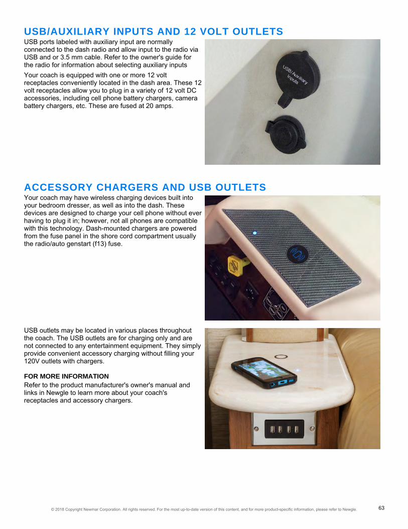
USB/AUXILIARY INPUTS AND 12 VOLT OUTLETSUSB ports labeled with auxiliary input are normallyconnected to the dash radio and allow input to the radio viaUSB and or 3.5 mm cable. Refer to the owner's guide forthe radio for information about selecting auxiliary inputsYour coach is equipped with one or more 12 voltreceptacles conveniently located in the dash area. These 12volt receptacles allow you to plug in a variety of 12 volt DCaccessories, including cell phone battery chargers, camerabattery chargers, etc. These are fused at 20 amps.
ACCESSORY CHARGERS AND USB OUTLETSYour coach may have wireless charging devices built intoyour bedroom dresser, as well as into the dash. Thesedevices are designed to charge your cell phone without everhaving to plug it in; however, not all phones are compatiblewith this technology. Dash-mounted chargers are poweredfrom the fuse panel in the shore cord compartment usuallythe radio/auto genstart (f13) fuse.
USB outlets may be located in various places throughoutthe coach. The USB outlets are for charging only and arenot connected to any entertainment equipment. They simplyprovide convenient accessory charging without filling your120V outlets with chargers.
FOR MORE INFORMATIONRefer to the product manufacturer's owner's manual andlinks in Newgle to learn more about your coach'sreceptacles and accessory chargers.
© 2018 Copyright Newmar Corporation. All rights reserved. For the most up-to-date version of this content, and for more product-specific information, please refer to Newgle. 63
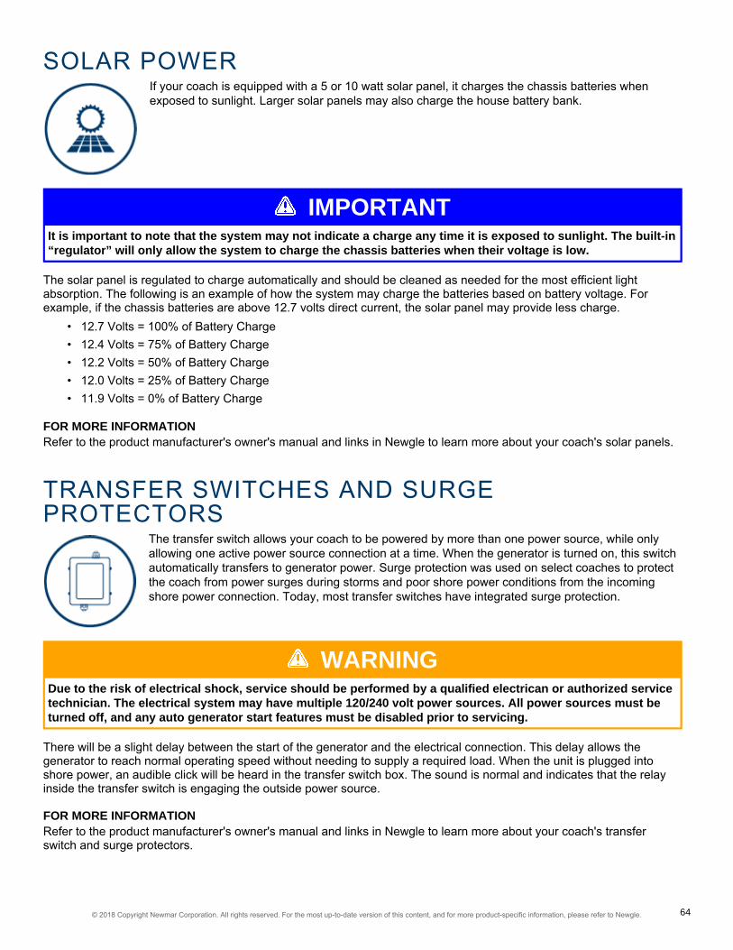
SOLAR POWERIf your coach is equipped with a 5 or 10 watt solar panel, it charges the chassis batteries whenexposed to sunlight. Larger solar panels may also charge the house battery bank.
IMPORTANTIt is important to note that the system may not indicate a charge any time it is exposed to sunlight. The built-in“regulator” will only allow the system to charge the chassis batteries when their voltage is low.
The solar panel is regulated to charge automatically and should be cleaned as needed for the most efficient lightabsorption. The following is an example of how the system may charge the batteries based on battery voltage. Forexample, if the chassis batteries are above 12.7 volts direct current, the solar panel may provide less charge.
• 12.7 Volts = 100% of Battery Charge• 12.4 Volts = 75% of Battery Charge• 12.2 Volts = 50% of Battery Charge• 12.0 Volts = 25% of Battery Charge• 11.9 Volts = 0% of Battery Charge
FOR MORE INFORMATIONRefer to the product manufacturer's owner's manual and links in Newgle to learn more about your coach's solar panels.
TRANSFER SWITCHES AND SURGEPROTECTORS
The transfer switch allows your coach to be powered by more than one power source, while onlyallowing one active power source connection at a time. When the generator is turned on, this switchautomatically transfers to generator power. Surge protection was used on select coaches to protectthe coach from power surges during storms and poor shore power conditions from the incomingshore power connection. Today, most transfer switches have integrated surge protection.
WARNINGDue to the risk of electrical shock, service should be performed by a qualified electrican or authorized servicetechnician. The electrical system may have multiple 120/240 volt power sources. All power sources must beturned off, and any auto generator start features must be disabled prior to servicing.
There will be a slight delay between the start of the generator and the electrical connection. This delay allows thegenerator to reach normal operating speed without needing to supply a required load. When the unit is plugged intoshore power, an audible click will be heard in the transfer switch box. The sound is normal and indicates that the relayinside the transfer switch is engaging the outside power source.
FOR MORE INFORMATIONRefer to the product manufacturer's owner's manual and links in Newgle to learn more about your coach's transferswitch and surge protectors.
© 2018 Copyright Newmar Corporation. All rights reserved. For the most up-to-date version of this content, and for more product-specific information, please refer to Newgle. 64
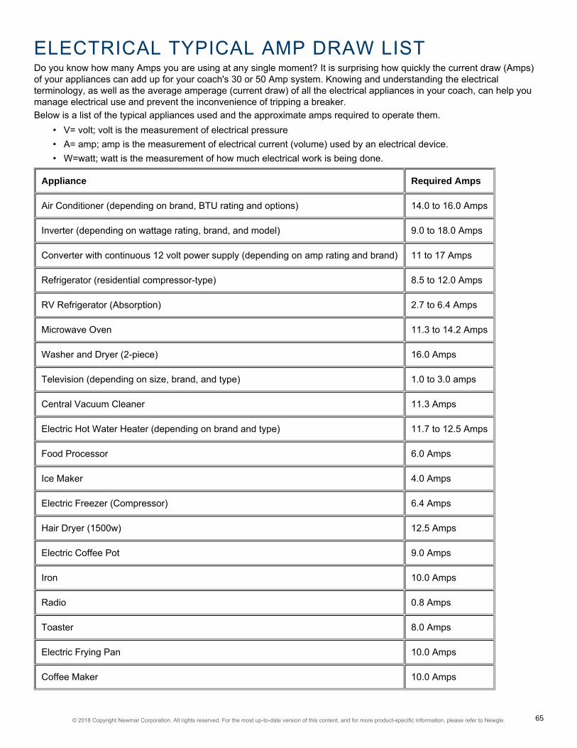
ELECTRICAL TYPICAL AMP DRAW LISTDo you know how many Amps you are using at any single moment? It is surprising how quickly the current draw (Amps)of your appliances can add up for your coach's 30 or 50 Amp system. Knowing and understanding the electricalterminology, as well as the average amperage (current draw) of all the electrical appliances in your coach, can help youmanage electrical use and prevent the inconvenience of tripping a breaker.Below is a list of the typical appliances used and the approximate amps required to operate them.
• V= volt; volt is the measurement of electrical pressure• A= amp; amp is the measurement of electrical current (volume) used by an electrical device.• W=watt; watt is the measurement of how much electrical work is being done.
Appliance Required Amps
Air Conditioner (depending on brand, BTU rating and options) 14.0 to 16.0 Amps
Inverter (depending on wattage rating, brand, and model) 9.0 to 18.0 Amps
Converter with continuous 12 volt power supply (depending on amp rating and brand) 11 to 17 Amps
Refrigerator (residential compressor-type) 8.5 to 12.0 Amps
RV Refrigerator (Absorption) 2.7 to 6.4 Amps
Microwave Oven 11.3 to 14.2 Amps
Washer and Dryer (2-piece) 16.0 Amps
Television (depending on size, brand, and type) 1.0 to 3.0 amps
Central Vacuum Cleaner 11.3 Amps
Electric Hot Water Heater (depending on brand and type) 11.7 to 12.5 Amps
Food Processor 6.0 Amps
Ice Maker 4.0 Amps
Electric Freezer (Compressor) 6.4 Amps
Hair Dryer (1500w) 12.5 Amps
Electric Coffee Pot 9.0 Amps
Iron 10.0 Amps
Radio 0.8 Amps
Toaster 8.0 Amps
Electric Frying Pan 10.0 Amps
Coffee Maker 10.0 Amps
© 2018 Copyright Newmar Corporation. All rights reserved. For the most up-to-date version of this content, and for more product-specific information, please refer to Newgle. 65

CONVERSIONSYou can look at at your electrical appliances, find the label that contains amperage or wattage ratings and calculateexact usage by using the formulas below.
• Watts/Volts = Amps• Amps x Volts = Watts• Watts/Amps = Volts
EXAMPLEMost products requiring electricity provide how many amps or watts it typically utilizes. If your electric hot water heater isalways in use (~12.5 amps), and you start your air conditioner (~15.0 Amps) and put on a pot of coffee (~9.0 amps) andmake some toast (~8.0 amps) while watching TV (~ 2.0 amps), you have far exceeded the 30 amp service, resulting in atripped breaker. Many people don't take into consideration how much power may be used by the inverters chargingcircuits mostly because they are working automatically in the background. 50 amp service has two 50 amp power legs,providing a total service of 100 amps.
© 2018 Copyright Newmar Corporation. All rights reserved. For the most up-to-date version of this content, and for more product-specific information, please refer to Newgle. 66

ELECTRONICSMultiple coach functions can be controlled at the tips of your fingers, including surveillance andsecurity, lighting, holding tank monitoring, and if equipped, the total coach management system.This category provides detailed information about each of the electronic components available inyour coach. Under each sub-category, you will have access to owners manuals, user guides, partsand service manuals, and product specifications for each of the electronics available in yourNewmar coach.
NOTICEFor detailed information see your owner manual for the specific item or refer to Newgle. Audio-VisualEquipment information is located in the Entertainment Systems category.
CAMERA AND VIDEO MONITORING SYSTEMSThis closed circuit television system features cameras mounted on the exterior of your coach and isconnected to the in-dash video screen. This system comes on automatically when you put thetransmission in reverse to allow you to see behind your unit when backing up. Additionally, it can bemanually turned on in transit to allow you to monitor your towed vehicle or for additional assistancein passing maneuvers.
REAR VIEW CAMERASInstalled as a standard feature, the rear view monitor system assists the driver in the backing and parking of the vehicle.This system consists of a camera mounted on the rear cap and a monitor located on the dash.
SIDE VIEW CAMERASAs an option for the rear vision system, your unit may be equipped with “side view” cameras. These cameras are tiedinto the rear vision system and are activated by the turn signals. When a turn signal is activated, the monitor will switchto display that side of the unit. Once the turn signal cycle is complete, the display will revert back to the previous camerafor the Voyager system and Xite system. In some Xite systems, the camera selection may default back to the rearcamera.
CAMERA SELECTIONIf the rear vision monitor is turned on manually, you can toggle through the cameras by using the “Source” button on theVoyager system, or the "Menu" button followed by the "Camera Select" icon on the Xite system, allowing you to stay onany given camera that you choose unless a reverse or turn signal is detected. Select Xite systems may have a "CAM"button that serves as a shortcut to the camera settings.
FOR MORE INFORMATIONRefer to the product manufacturer's owner's manual and links in Newgle to learn more about your coach's cameras andvideo monitoring system.
© 2018 Copyright Newmar Corporation. All rights reserved. For the most up-to-date version of this content, and for more product-specific information, please refer to Newgle. 67

HOLDING TANK MONITORINGThe monitor panel allows you to check the approximate levels in the fresh, gray, and black waterholding tanks, as well as propane levels (if equipped), and the battery condition. The monitor panelis generally located above or near the entrance door. An additional monitor panel may be located inthe basement water compartment.
FOR MORE INFORMATIONRefer to the product manufacturer's owner's manual and links in Newgle to learn more about your coach's holding tankmonitoring system.
PRECISION CIRCUITS HOLDING TANK MONITORING SYSTEMS1
"The Digital Monitor Panel digitally displays the levels of the Water and Waste Tanks, andL.P. Tank. It provides both a digital and analog Battery Volt Meter. Optionally it can alsodisplay the Generator Hour Meter."
"The Tank Sensor features field effect technology, a non-invasive method. Each Sensor array contains three sensorswhich glue externally to the polymer tank wall with high-grade long life adhesive, at the position and level that the wateris to be sensed, thus eliminating the need for calibration. Each Sensor emits an electric field into the tank. When thewater level passes by the Sensor, it detects a change in its electric field."
IMPORTANTThese brief operation instructions are for quick reference only. Any quick start instructions provided shouldnot take the place of the complete Operation Manual provided by this item's manufacturer.
PERFORMING A LEVELS CHECKFor coaches not equipped with the SilverLeaf system,simply press the "Levels Check" button to check the tanklevel statuses. The levels will show on the digital display.
MONITOR PANEL CALIBRATIONThe monitor panel has been calibrated for accuracy prior toleaving the factory and should not need to be adjusted. Inthe event that the system does not read accurately, then re-calibration may be necessary. Follow the manufacturer'sprocedures for re-calibration for your specific product. It isrecommended to have a qualified service technicianperform the re-calibration procedure.
1 Material sourced from Precision Circuits Digi-Level Digital Monitor Panel
© 2018 Copyright Newmar Corporation. All rights reserved. For the most up-to-date version of this content, and for more product-specific information, please refer to Newgle. 68

NAVIGATION SYSTEMSYour coach may be equipped with a GPS based Navigation system. This system uses GPStechnology to guide you through maps and information for traveling assistance. It features voiceprompts and touchscreen technology to make scrolling through the menus and getting informationincredibly easy.
WARNINGThe navigation system is NOT intended to replace, supersede, or take precedence over any traffic signs,street signs, hazard signs, etc.
The navigation feature is intended to assist you with guidance to your destination. The system may need software andmap updates. Updates are not warrantable issues, as roadways change over time and construction takes place, themaps and/or systems may become obsolete.
CAUTIONIt is the driver's responsibility to make sure the roads are safe and appropriately navigated and roadwayweight limits and clearances are rated for the vehicle you are driving.
FOR MORE INFORMATIONRefer to the product manufacturer's owner's manual and links in Newgle to learn more about your coach's navigationsystem.
WIFI SYSTEMSDue to the ever-growing demand of internet connectivity, a WiFi system in your coach can mean thedifference between using costly mobile data and being able to access free WiFi wherever yourtravels may take you. Your coach may be equipped with one of the many options WiFi systemsNewmar offers.
FOR MORE INFORMATIONRefer to the product manufacturer's owner's manual and links in Newgle to learn more about your coach's WiFi systems.
© 2018 Copyright Newmar Corporation. All rights reserved. For the most up-to-date version of this content, and for more product-specific information, please refer to Newgle. 69

70© 2018 Copyright Newmar Corporation. All rights reserved. For the most up-to-date version of this content, and for more product-specific information, please refer to Newgle.

ENTERTAINMENT SYSTEMSNewmar partners with the most prestigious names in mobile lifestyle, entertainment and technology.These brands are leaders in their fields – and legends in providing customers with new,unsurpassed levels of quality and reliability. Best in class performance from names you can trust.Stay entertained on the road and off, with spectacular visual and sound options from industryleaders.
This section provides information on entertainment components, including televisions, dash-mounted audio equipment,multi-disc players, home theater systems, and satellite antennas. Such components may be located within your coach'sliving room, bedroom, cargo area, or even outside of your unit in an optional exterior entertainment center.
NOTICESome of the components are optional and may not be installed in your coach.
EXTERIOR ENTERTAINMENT CENTERFor your convenience and pleasure, an Exterior Entertainment Center may be an option on selected floorplans. It maybe located in either a basement compartment or in the sidewall of the passenger side of the coach. Depending on theyear, model, and floorplan of your coach, this entertainment center features an flat screen television, and may feature anAM/FM/CD stereo and speakers to provide outside music when desired. Some coach models feature a sound barinstead, and may also have an audio selector switch.The television is mounted on a swivel bracket that allows you to swing the television out and away from the coach toprovide better viewing angles. To release the television from its retainers, grasp the sides of the television firmly and pullit directly toward you. It will release and swing freely to the desired viewing position. To store the television for travel,swing it back into the opening, making sure that it is fully latched.The external stereo can be used to listen to AM and FM broadcasts, as well as to play CDs. It may have some of thesame functions and features as your in-dash stereo. The television in the exterior entertainment center can also beplayed through the exterior stereo or sound bar. If equipped with audio selector rotate switch to desired audio input forthe sound bar.
IMPORTANTIt is important to make sure the TV is securely locked into position prior to closing the compartment door.Failure to do so can result in damage to the television case and screen.
IMPORTANTThe electronics used in the Exterior Entertainment Center are not designed for use in wet weather. The TVshould be stored securely in the “travel” position and the basement door closed during rain or other adverseweather conditions. Caution should also be exercised when washing the exterior of your coach to make surehigh pressure water does not enter the compartment. Spraying high pressure water at the seal between thedoors can cause leaks, and potentially damage the electronics housed in this compartment.
TOY HAULER GARAGE ENTERTAINMENT SYSTEMThis entertainment center incorporates a television and stereo. The television can be used to tune local channels via theantenna (not connected to the DVD player inside the unit). The AM/FM/CD stereo is connected to multiple speakers inthe garage area, as well as under the awning on the passenger side of the coach. The speakers can be turned on andoff using the switch located inside the cabinet door above the radio.
© 2018 Copyright Newmar Corporation. All rights reserved. For the most up-to-date version of this content, and for more product-specific information, please refer to Newgle. 71

INVERTER-POWERED COMPONENT TROUBLESHOOTINGIf your entertainment components or certain appliances are not working, such as television, DVD player, satellitesystem, refrigerator, or microwave, Newmar recommends checking the breaker on the inverter, which may be located ina compartment or between the chassis frame rails.
ANTENNAS, CABLE, AND SATELLITE SYSTEMSYour unit may be equipped with an exterior antenna jack and interior antenna jacks or wiring at eachtelevision location. Depending on your coach year, model, and options, several antennas have beenused.
An antenna with a power booster may be installed in your coach and is designed for reception of all local color andblack-and-white channels. The antenna may be automatic, stationary, or manual lift. The power booster supplies voltageto the antenna when using over-the-air signal. However, it transfers the connection from the antenna to park cable whenit is available and connected.
OVER-THE-AIR SIGNALIf the reception is poor, make sure the power switch for the power booster is in the “ON” position and all of the coaxconnections are tight. This switch is usually located beside the passenger chair or on the video selector box (select unitsonly).
CABLE CONNECTIONAn exterior cable jack and receptacle may be available on your coach. If installed, they may be located in an outsidestorage compartment, usually near the power cord. When using park cable, it is necessary to turn the antenna boosteroff in order to allow the signal to travel to the television or selector switch (if equipped). This switch is usually locatedbeside the passenger chair; it can also be the power button on the video selector box (select units only).
IMPORTANTFailure to turn off the power booster switch to the antenna while using the park cable system may cause poorpicture quality.
FOR MORE INFORMATIONRefer to the product manufacturer's owner's manual and links in Newgle to learn more about your coach's antenna,cable, and satellite system.
BLU-RAY PLAYERSBlu-ray players offer full HD 1080p blu-ray disc playback. Many players also offer other features likestreaming and a variety of applications.
OPERATING THE BLU-RAY PLAYER1. To operate your blu-ray player, turn it on using the remote or on the face of the player.2. To insert a blu-ray disk, press the OPEN button, followed by the CLOSE button.3. Press the PLAY button on the remote or on face of the player.4. Make sure the proper source is selected on the television to view the blu-ray disk.
© 2018 Copyright Newmar Corporation. All rights reserved. For the most up-to-date version of this content, and for more product-specific information, please refer to Newgle. 72

FOR MORE INFORMATIONRefer to the product manufacturer's owner's manual and links in Newgle to learn more about your coach's blu-ray player.
DASH RECEIVERS, CD PLAYERS, AND STEREOSYour coach may be equipped with an AM/FM dash stereo radio with a built-in CD player. Somemodels may also include an auxiliary input jack for an iPod or MP3 player, or even offer bluetoothconnectivity. Others may also play DVD/CD, as well as several other disk formats.
FOR MORE INFORMATIONRefer to the product manufacturer's owner's manual and links in Newgle to learn more about your coach's dash receiver,CD player, or stereo.
DVD PLAYERSNewmar has installed a variety of DVD players to enhance your entertainment experience.
OPERATING THE DVD PLAYER1. To operate your DVD player, turn it on using the remote or on the face of the player.2. To insert a DVD, press the OPEN button, followed by the CLOSE button.3. Press the PLAY button on the remote or on face of the player.4. Make sure the proper source is selected on the television to view the DVD.
FOR MORE INFORMATIONRefer to the product manufacturer's owner's manual and links in Newgle to learn more about your coach's DVD player.
HEADPHONES, SPEAKERS, AND AMPLIFIERSNewmar has installed a variety of name brand products to enhance the audio in your coach fromspeakers and sound bars to amplifiers and digital processors.
FOR MORE INFORMATIONRefer to the product manufacturer's owner's manual and links in Newgle to learn more about your coach's speakers andamplifiers.
© 2018 Copyright Newmar Corporation. All rights reserved. For the most up-to-date version of this content, and for more product-specific information, please refer to Newgle. 73

INFRARED RECEIVERS, REMOTES, ANDSWITCHERS
On select coaches, all of the entertainment equipment can be operated with the use of a singleuniversal remote. Infrared signal repeaters and switching devices can help aid in receiving andtransmitting the signals to the proper place. Both systems work in conjunction to make yourentertainment equipment easier to use.
FOR MORE INFORMATIONRefer to the product manufacturer's owner's manual and links in Newgle to learn more about your coach's infraredreceivers, remotes, and switchers.
STEREO RECEIVERS AND HOME THEATERSYSTEMS
To enhance the entertainment experience, a home theater or stereo receiver system may beinstalled in your coach. This system allows you to enjoy music, TV, or videos from DVD/ blu-ray viaremote through a matching set of speakers and a subwoofer for deep, full bass sound. Select unitsmay also use sound bar technology in lieu of a multi-speaker system.
FOR MORE INFORMATIONRefer to the product manufacturer's owner's manual and links in Newgle to learn more about your coach's home theatersystem.
TELEVISIONSYour coach may be cable ready, and (depending on your floorplan) may have multiple flat screentelevisions installed throughout the unit. The televisions are powered by 120 volt electricity, and thecoach must be plugged into shore power, using the inverter (if equipped) or have the generatorrunning in order for the televisions to function. The television operation is similar to most televisionsused in the home.
IMPORTANTThese brief operation instructions are for quick reference only. Any quick start instructions provided shouldnot take the place of the complete Operation Manual provided by this item's manufacturer.
INTERIOR TELEVISIONSThe LED television(s) in your coach may be HD (High Definition) compatible, meaning they are capable of displaying theresolution and clarity of High Definition broadcasts and video sources.Your coach may also be pre-wired for a satellite system and may be equipped with one interior television jack and anexterior television jack located on the passenger side of the coach. Choose the television source by selecting the inputmode (air, cable, HDMI, etc.). The DVD player and satellite, if equipped, provides input to the front television(s) andexterior entertainment center. The bedroom DVD and satellite receiver, if equipped, provides input to the bedroomtelevision.
© 2018 Copyright Newmar Corporation. All rights reserved. For the most up-to-date version of this content, and for more product-specific information, please refer to Newgle. 74

IMPORTANTThe television in the front overhead cabinet will not operate while in transit. Federal regulations require thistelevision to be inoperative while the vehicle is in use, so the power supply is switched off automatically whenthe ignition is turned on.
EXTERIOR ENTERTAINMENT CENTERFor your convenience and pleasure, an Exterior Entertainment Center may be an option on selected floorplans. It maybe located in either a basement compartment or in the sidewall of the passenger side of the coach. Depending on theyear, model, and floorplan of your coach, this entertainment center features an flat screen television, and may feature anAM/FM/CD stereo and speakers to provide outside music when desired. Some coach models feature a sound barinstead, and may also have an audio selector switch.The television is mounted on a swivel bracket that allows you to swing the television out and away from the coach toprovide better viewing angles. To release the television from its retainers, grasp the sides of the television firmly and pullit directly toward you. It will release and swing freely to the desired viewing position. To store the television for travel,swing it back into the opening, making sure that it is fully latched.The external stereo can be used to listen to AM and FM broadcasts, as well as to play CDs. It may have some of thesame functions and features as your in-dash stereo. The television in the exterior entertainment center can also beplayed through the exterior stereo or sound bar. If equipped with audio selector rotate switch to desired audio input forthe sound bar.
IMPORTANTIt is important to make sure the TV is securely locked into position prior to closing the compartment door.Failure to do so can result in damage to the television case and screen.
IMPORTANTThe electronics used in the Exterior Entertainment Center are not designed for use in wet weather. The TVshould be stored securely in the “travel” position and the basement door closed during rain or other adverseweather conditions. Caution should also be exercised when washing the exterior of your coach to make surehigh pressure water does not enter the compartment. Spraying high pressure water at the seal between thedoors can cause leaks, and potentially damage the electronics housed in this compartment.
FOR MORE INFORMATIONRefer to the product manufacturer's owner's manual and links in Newgle to learn more about your coach's televisions.
© 2018 Copyright Newmar Corporation. All rights reserved. For the most up-to-date version of this content, and for more product-specific information, please refer to Newgle. 75

76© 2018 Copyright Newmar Corporation. All rights reserved. For the most up-to-date version of this content, and for more product-specific information, please refer to Newgle.

EXTERIORExperience as much, or as little, of the outdoors as you want in comfort and style. This categoryprovides information regarding the exterior components on your coach, such as compartments,doors, paint, roof, and many other standard and optional accessories. Under each sub-category,you will have access to owners manuals, user guides, parts and service manuals, and productspecifications for each of the exterior components available on your Newmar coach.
AIR HORNSAir horns may be installed on your coach, in addition to the horn installed on the chassis. Air hornson Newmar products may be located on the roof or under the front cap depending on year, andmodel.
HOW TO OPERATE THE AIR HORNThe Air Horn Switch located in the driver area allows the driver to choose between the air hornor the standard city horn. The Air Horn Switch may be located in one of various locations basedon coach model and year, but will always be within the driver's reach.
1. With the Air Horn Switch turned on and adequate air pressure in the air tanks, pressthe horn icon on the steering wheel to sound the air horn.2. With the Air Horn Switch turned off, press the horn icon on the steering wheel to soundthe standard city horn.
FOR MORE INFORMATIONRefer to the product manufacturer's owner's manual and links in Newgle to learn more aboutyour coach's air horns.
AWNINGSAwnings are a standard feature on your coach. Newmar offers a variety of brands and types ofawnings, depending on the year and model of your coach, as well as the available options that wereselected at the time of your coach's manufacture. Select models may feature slideout toppers,entrance door, and or window awnings.
The patio awnings are the larger-sized awning on the coachand are the main awning. These awnings connect at or nearthe roof, providing shade, light, and rain protection on thepassenger side of the coach.
HOW TO OPERATE YOURAWNINGSThe powered patio, window, and door awnings (if equipped)on your coach can be operated with ease. Use theappropriate switches to extend or retract the awnings asdesired. Slideout toppers or covers operate as the slideoutsare extended and retracted.
© 2018 Copyright Newmar Corporation. All rights reserved. For the most up-to-date version of this content, and for more product-specific information, please refer to Newgle. 77

The switch is typically located in the overhead above the driver seat. If they are not at this location, check above thepassenger window, as it is usually hidden by the shade for the window. Some coach awnings may also operated via aremote control or the SilverLeaf Virtual Keypad.
IMPORTANTPrior to extending any of your coach awnings, check for any obstructions that may prevent the awnings fromdeploying properly. Inspect the area around your unit where the awning will extend to ensure properclearance.
NOTICEDamage to your awnings as a result of weather is not covered by warranty.
FOR MORE INFORMATIONRefer to the product manufacturer's owner's manual and links in Newgle to learn more about your coach's awnings.
COMPARTMENTSStorage compartments are located on the exterior sides of your unit. These compartments provideadditional space for your belongings while you are traveling. Select coach models feature optionalmanual slide trays and standard lighting, while others may feature compartments complete withpower slide trays, dual side access, and automatic LED lighting throughout the storage area.
IMPORTANTBefore traveling, perform a pre-trip inspection that includes checking each baggage door to ensure each oneis latched and locked securely.
EXTERIOR WATER COMPARTMENTAll plumbing functions can be controlled from this location. Additionally, the connection points for city water, sewer rinse,and holding tank draining are all located in this compartment. For more detailed information, refer to the Fresh WaterSystem and Waste Water System pages under the Plumbing category.
STORAGE COMPARTMENTSUse caution when packing the storage areas. Do not pack items around water heaters, refrigerators, furnaces, hydronicheating units, or any other heat-producing appliances.
GENERATOR COMPARTMENTSelect coach models are equipped with a powered generator slide compartment to provide easier access to thegenerator, fire wall, and other components located below the dash between the front cap and the firewall.Do not place anything in front of or between the slide area of the front bumper and cap, including persons, while inoperation or during service of the slide system.
© 2018 Copyright Newmar Corporation. All rights reserved. For the most up-to-date version of this content, and for more product-specific information, please refer to Newgle. 78

PUSH BUTTON-ACTIVATED COMPARTMENT LOCKSSelect coach models may be equipped with storage compartments with push button locks. Under normal operation,push the button to release the door.In the event of a power failure, the compartments can be manually accessed using the cable loop or cable lock featurelocated underneath most compartments. The pass-through bays are the exception, as they may have only onecompartment with access on each side.To manually access the compartments equipped with a cable lock, insert the #751 key into the lock hidden at the bottomof compartment by the radius of the compartment door.To access the compartments equipped with a cable loop, locate the cable loop under the compartment near the latchside, and pull on the cable until the compartment door releases. Most cables will pull straight down to release. Thebattery compartment cable releases easier by pulling toward the back of the coach.
FOR MORE INFORMATIONRefer to the product manufacturer's owner's manual and links in Newgle to learn more about your coach'scompartments.
DOORS, HANDLES, AND CHIMESThe front entrance door is equipped with a dead bolt lock for added security, and select coachmodels may have a power flush step well cover. For your safety and convenience, all currentmodels feature a grab handle at the entrance door to assist you in entering and exiting the coach.Select models may incorporate the keyless entry system, and many have a doorbell buttonintegrated into the grab handle as well.
When the door is opened fully, the door has a "door check" feature that will automatically hold the door open. To closethe door, simply pull to release the detent, then close and latch the door. Center entry doors may incorporate a gas strutto hold the door open.
FOR MORE INFORMATIONRefer to the product manufacturer's owner's manual and links in Newgle to learn more about your coach's entrancedoors, handles, and chimes.
© 2018 Copyright Newmar Corporation. All rights reserved. For the most up-to-date version of this content, and for more product-specific information, please refer to Newgle. 79

ENTRANCE STEPSYour coach may be equipped with electric entrance door steps. Select coach models may beequipped with hydraulic steps. Both types of steps automatically extend when the entrance door isopened and retract when the entrance door is closed.
IMPORTANTThese brief operation instructions are for quick reference only. Any quick start instructions provided shouldnot take the place of the complete Operation Manual provided by this item's manufacturer.
ELECTRIC STEPSYour coach may be equipped with electric entrance door steps. When the power switch for the steps is in the ONposition, simply open the door, and the steps will open. To operate the electric steps:
1. Turn the step power switch ON.2. Close the door. The step should retract and close completely.3. Open the door. The step should extend and open completely.4. Turn the step power switch OFF. The step should remain in the extended position when the door is closed.Turning off the power with the step retracted will keep the step in a retracted position.5. With the step extended, turn the step power switch OFF, and close the entrance door.6. Turn on the vehicle ignition. The ignition override system will turn on, and the step will automatically retract.7. Turn off the vehicle ignition, and open the door. The step will extend and open completely.
HYDRAULIC STEPSSelect coach models may be equipped with hydraulic steps. With the entry door step switch turned on in the frontoverhead cabinet, this step extends when the door is opened and retracts when the door is closed (as long as the parkbrake is set). Opening and closing the door will automatically shut down the pump at the end of the step cycle.
NOTICEIt is normal for the pump to run for a short time after the step is retracted.
During deployment, the step will stop if the shin guard or curb feeler is touched by an object. The curb feeler is mountedto the bottom of the lowest step, and the shin guard is mounted to the step face of the lowest step.
CAUTIONDo not sit or stand on the step when the door is being closed, as it retracts when the door switch is activated.
WARNINGDo not sit or stand on the step with the ignition on if the parking brake is going to be released. The step mayretract automatically regardless of the door or on /off switch position.
The exterior switch can be turned off once the step is extended. This will prevent the step from opening and closingeach time the door is opened or closed. The step will extend one time after it has retracted with the switch in the offposition.
© 2018 Copyright Newmar Corporation. All rights reserved. For the most up-to-date version of this content, and for more product-specific information, please refer to Newgle. 80

OVERRIDE SWITCHWhen equipped, this switch is located in the passenger side console.
IMPORTANTMake sure the path of the step is clear. Pressing the override switch disables the curb and shin guardsensors. Stop the step before it contacts any objects or the ground. Failure to do so may result in severedamage to the step or contacted objects. Using the override switch will extend the step during switchactivation at any time unless the park brake is released. Releasing the park brake will disable the overrideswitch.
RESET SWITCHWhen equipped, this switch is located in the overhead cabinet. In the event the HWH system is inactive, press and holdthe reset switch for five seconds. Then release the switch, and attempt system operation again.
FOR MORE INFORMATIONRefer to the product manufacturer's owner's manual and links in Newgle to learn more about your coach's entrancesteps.
EXTERIOR LIGHTSThe lights installed on the exterior of your coach, such as headlights, taillights, accent lights,decorative lights, floodlights, spotlights, and security lights, are used for a variety of purposes. Manydifferent types of light bulbs are used in the lights, and some lights require total replacement overtime.
LIGHT MAINTENANCEIt is necessary to keep exterior lights clean, as dirty lights have diminished output and reduced visibility. To clean yourexterior lights, use a mild soap designed for automotive car washing. Avoid using harsh cleaners, abrasive products,and petroleum-based products or other chemicals.
IMPORTANTAlways check the operation of all headlights, turn signals, and clearance lights prior to traveling.
REPLACING THE LIGHT BULBSReplace any exterior light bulbs or fixtures as needed to maintain DOT safety requirements. When servicing interior orexterior lights, make sure you replace any light bulb with the same bulb number (normally stamped on the base of thebulb or printed on the bulb). Replacing the bulb with the identical part number will ensure the wattage and base are thesame.
WARNINGDo not substitute bulbs just because they will fit, as it may cause overheating, back feed, or damage to thelight fixture or lens.
Many of these bulbs are made as both filament and LED. Most LED bulbs are polarity-sensitive unlike filament bulbs.When attempting to replace filament-type bulbs with LED-type bulbs, it is possible for the light fixture to be wired inreverse polarity for the LED replacement bulbs. Switching to a different type of bulb may require a wiring change.Newmar recommends any wiring modifications be performed by an authorized service technician.
© 2018 Copyright Newmar Corporation. All rights reserved. For the most up-to-date version of this content, and for more product-specific information, please refer to Newgle. 81
IMPORTANTWhen replacing halogen bulbs, do not touch the bulb, as the oil from your hands will reduce the bulb's life.
Turn off the lights to avoid possible short circuits, blown fuses, and burns while removing and replacing bulbs or lights.Depending on the year and model of your coach, it may be equipped with LED light fixtures with the lights embeddedinto the light housing. Many of the LED light fixtures have integrated LED assemblies that are non-serviceable and non-replaceable. When LED light bulbs burn out this type of fixture, the complete light must be replaced. Replacement bulbsor light fixtures are available for purchase through the Newmar Parts Department.
HEADLIGHTSThe coach may have headlights installed that are atmospherically vented, so condensation may occur in these headlightassemblies. Under normal driving conditions with the headlights turned on, the condensation will dissipate, allowing it toescape through the vent.
FOR MORE INFORMATIONRefer to the product manufacturer's owner's manual and links in Newgle to learn more about your coach's exterior lights.
HITCHES AND TOWING COMPONENTSYour motorhome is equipped with a hitch and tow plug, as it is designed for towing light loads. Your hitch may provideyou with the capability of towing your car or trailer while traveling. A wiring harness or pigtail is needed to connect taillights, brake lights, turn lights, etc. of the towed vehicle with that of the coach. Some coach models feature rear dockinglights to assist with tow vehicle hookup at night.Prior to towing, inspect all towing connections, including the hitch mounting bolts for unusual wear or corrosion. Checkthe mounting flanges for any deformation, as well as the hitch welds for any cracks, signs of movement, or fatigue in thehitch assembly. Safe and satisfactory performance of the towing system depends on the type of towing equipmentconnected to the hitch receiver. The assembled length of the drawbar/towing system used should be kept to a minimum.Do not exceed the rated capacities of the hitch or the components used to attach the towed vehicle or trailer.
IMPORTANTNewmar is not responsible for damage or failure of the hitch receiver caused by the use of excessively longdrawbars or other styles of drawbars that create leverage loads on the hitch receiver beyond its designedcapabilities.
The total weight of the motorhome and any vehicle towed must not exceed the GCWR (Gross Combined WeightRating). When planning to tow, approaching the GVWR (Gross Vehicle Weight Rating) may reduce the motorhome’stowing capacity. When weighing the motorhome, be sure to take passenger locations into consideration. The towedvehicles must have adequate active brakes. Contact your state Department of Transportation or your local Newmardealer for your state requirements.
FOR MORE INFORMATIONRefer to the product manufacturer's owner's manual and links in Newgle to learn more about your coach's hitch andtowing components.
LADDERSIf equipped, the exterior rear ladder provides access to the roof for maintenance of the roof and roof-mounted items.
© 2018 Copyright Newmar Corporation. All rights reserved. For the most up-to-date version of this content, and for more product-specific information, please refer to Newgle. 82

IMPORTANTObjects viewed in the convex mirrors are closer thanthey appear.
IMPORTANTWhen going up or down the ladder, make sure the ladder is clear of debris, ice, water and any other slipperysubstance. Wear shoes that provide good traction. Slip-on shoes are not recommended when using theladder.
IMPORTANTThe rear ladder maximum weight capacity may differ by manufacturer and dimensions of the ladder. Observeand do not exceed the weight rating for your ladder, which may be noted on the bottom of one of the ladderrungs.
MIRRORSYour coach may be equipped with convex remote-controlled two-part exterior rear view mirrors. Thetop portion of the mirror is flat, providing conventional reflected views down the sides of the RV,while the bottom portion is convex to provide an expanded view, helping to eliminate blind spots.These mirrors may also contain heating elements to defog, defrost, or de-ice the mirror glass during
cold weather operation. Some mirrors can be operated via remote control.
IMPORTANTThese brief operation instructions are for quick reference only. Any quick start instructions provided shouldnot take the place of the complete Operation Manual provided by this item's manufacturer.
Always adjust the mirrors for maximum rear visibility prior to driving. These mirrorsare adjusted by using the multi-directional switches located on the driver’s door(optional on some models) or console. Make sure the seat is positioned for propervehicle control, and then adjust the mirrors for maximum rear visibility prior to driving.Select the mirror to be adjusted by pointing the arrow in the direction of that mirror.Move the control in the direction of movement desired to obtain the best view.The ON/OFF switch for this feature is located by the adjustment control. Theadjustment control moves the top half of both mirrors. The bottom half of the mirror isconvex and is adjusted manually. Use the red switch to turn ON and OFF the heatedmirror feature (if equipped).
FOR MORE INFORMATIONRefer to the product manufacturer's owner's manual and links in Newgle to learn more about your coach's mirrors.
© 2018 Copyright Newmar Corporation. All rights reserved. For the most up-to-date version of this content, and for more product-specific information, please refer to Newgle. 83

PAINT, ROOF, AND SIDINGNewmar RV sidewalls are designed with structure to make them more rigid and dependable. Bybuilding aluminum frames with studs 16 inches on center, your sidewalls and roof will form a strong,lightweight, integrated structure so you can enjoy superior insulation. The Newmar Full-PaintMasterpiece™ Finish is one of the most stunning and durable in the industry. And it comes standardon every full-paint Newmar model, from our most affordable to our most luxurious.
IMPORTANTThese brief operation instructions are for quick reference only. Any quick start instructions provided shouldnot take the place of the complete Operation Manual provided by this item's manufacturer.
PAINTWe’re passionate about paint. And we believe that the RV we create for you should be as beautiful as it is comfortable.Our coaches are more gorgeous than ever, with a sleek, stunning exterior showcased by all-new graphics and theexquisite Full-Paint Masterpiece™ Finish. Our goal is to create a perfect finish every time we paint a Newmar. This ishow we do it:
• Between 12 and 16 gallons of paint are used on each model.• Several types of primer are applied, followed by a base coat, color for graphics and a final, clear coat.• We use materials of only the highest quality and integrity.• Our technicians are among the most knowledgeable and highly experienced.• The equipment and techniques we have created are among the most advanced.
We always ensure that each coat of paint lays flat and smooth to produce a stunning brilliance. That’s how we canpromise that your Newmar RV will offer you an exterior of the highest quality and durability.For cleaning and waxing instructions and recommended products, refer to the Miscellaneous Care and Maintenancesection in Newgle. Paint codes are typically posted on the back side of one of the upper kitchen cabinet doors.
DIAMOND SHIELD PAINT PROTECTIONIf your coach utilizes a Diamond Shield Paint Protector, follow the use and care guidelines as outlined by DiamondShield:1
IMPORTANTOnce applied, refrain from washing for 48 hours, washing after that time presents no problems. Do NOT useharsh or abrasive cleaners or detergents.
"We do not recommend ANY of the dry wash types of cleaners as they are intended for non-porous surfaces, paintprotection films are a porous material. Car wash type soap is recommended. Bugs should be washed off ASAP...Use extreme care if using a pressure washer, too high of a pressure or misuse of pressure washer may cut or tear thefilm. Pressure washer damage is NOT covered by Diamond Shield's warranty. The application of ANY products overDiamond Shield i.e. vinyl bras, banners, etc. will void the Diamond Shield warranty... Prior to putting coach/vehicle instorage Diamond Shield should be cleaned and waxed... Do not use wax designed for specific colors."
ROOFThis unit is manufactured with a 7mm decking material covered with fiberglass or rubber membrane. Proper care androutine maintenance of your roof is necessary for trouble-free performance. Inspection of roof seams and joints shouldbe performed by an Authorized Newmar Service Center annually.
© 2018 Copyright Newmar Corporation. All rights reserved. For the most up-to-date version of this content, and for more product-specific information, please refer to Newgle. 84

For improved lighting and headroom, a skylight may also be installed in the bathroom over the shower. The openingprovides additional light during daylight hours, and the skylight is tinted to provide privacy and reduce glare.For units equipped with roof drains, it is important to make sure the roof drain catch basin strainers are cleaned and keptfree of debris. There are four (4) of them, and they are located at the front and rear ends of the roof gutters, on both theleft and right sides. Regular cleaning and maintenance is essential to insuring a long, trouble-free life. Before cleaning, itis important that you inspect the sealants and gaskets used to seal components to the roof structure to be certain thereis no leakage during the cleaning process. Any cracks or voids in the sealants and seals MUST be repaired prior tospraying the roof with water. Extreme caution should be used when inspecting or cleaning the roof.
WARNINGIt is recommended that access, cleaning, and maintenance be conducted by a qualified professional at yourlocal dealership. Use caution if working on top of your vehicle. The wet roof surface is extremely slippery.
SIDINGThe sidewalls and end caps of your coach are constructed of smooth fiberglass, which is features an automotive style“Clear-Coat / Color Coat” painted finish.
SEALSThe seals around doors, windows, vents, slide out trim and external seams should be checked at least twice a year. Inaddition, the roof seams should be inspected twice a year for cracking or peeling. If deterioration is noted during aroutine maintenance inspection, reseal the seams or seals with an approved sealant to prevent leaks. Your dealer canperform the resealing inspections and work for you. It is recommended that a Newmar Authorized Service Centerperform these inspections, and reseal when necessary.
MAINTENANCEClean the fiberglass material with a mild cleanser and warm water. Use only soft cloths. Using stiff bristle brushes maycause scratches in the fiberglass surface. Please refer to the information provided by the paint manufacturer for morecleaning and maintenance details.
IMPORTANTNewmar is not responsible for weathering/oxidation of gel-coated surfaces.
FOR MORE INFORMATIONRefer to the product manufacturer's owner's manual and links in Newgle to learn more about your coach's paint, roof,and siding.
1 Material sourced from Diamond Shield Product Care
WINDOWSThe windows installed in your coach are either single or double pane tinted safety glass. Mostcurrent models offer sliding glass windows. A power window may be installed on the driver’s side onselect models.
© 2018 Copyright Newmar Corporation. All rights reserved. For the most up-to-date version of this content, and for more product-specific information, please refer to Newgle. 85

EMERGENCY EXIT WINDOWSThere is an emergency exit (egress) window in the bedroomdesigned to be used as an additional exit in emergencysituations. It can be easily identified by the red color of thehandle and the red EXIT label.
HEHR EGRESS EMERGENCY EXIT WINDOWSelect Hehr windows have an opening window pane in theegress window for ventilation. This style of window can alsobe opened in the event of an emergency.
TO OPEN THE VENT:1. Unclip and lower the arm.2. Swing the arm 90 degrees, and push out on thearm until the red handle latches.
TO CLOSE THE VENT:1. Unclip the red handle from the latch by liftingslightly while pushing outward.2. Once the latch releases, pull the arm in until thewindow is closed.3. Rotate the arm 90 degrees until it latches into theclosed position.
IN THE EVENT OF AN EMERGENCY, OPEN THE WINDOW:1. Remove the screen by pulling out on the red handle.2. Push and release the lever from the locking hook.3. Rotate the lever 90 degrees, and push it through the slot in the window frame.4. Escape through the opening.
HEHR DOUBLE-LATCHED EMERGENCY EXIT WINDOWTO OPEN THE EMERGENCY EXIT DOUBLE LATCHSTYLE WINDOW:
1. Flip both latches up to the open position.2. Push out on the window.
TO CLOSE AND LATCH THE EMERGENCY EXITDOUBLE LATCH STYLE WINDOW:
1. Pull the window shut while holding the windowtrack with one hand.2. With the other hand, rotate the latch up until itconnects with the track on the window.3. Press the front side down until it latches.4. Repeat the steps for the second latch.
HOW TO CLEAN THE WINDOWSMost windows used by Newmar are equipped with sliding screens that can be removed for cleaning.
© 2018 Copyright Newmar Corporation. All rights reserved. For the most up-to-date version of this content, and for more product-specific information, please refer to Newgle. 86

1
REMOVING THE SCREENOpen the window and screen. Press upward on the screen frame top, pushing the frame deeper into its pocket. This willcompress the springs and allow the screen frame bottom to rotate out of the bottom track. Be careful with the plasticscreen springs, so that they can be re-used.
CLEANING THE GLASSApply straight mineral spirits to a clean, soft cloth and wipe the glass. Dry with a clean cloth Next, clean the glass again,using a clean cloth with a 50-50 mix of water and a household window cleaner like Windex™ or GlassPlus™. If there isstill a residue, remove it with rubbing alcohol and dry.
HOW TO PREVENT WINDOW CONDENSATION
IMPORTANTSince surface condensation within the coach cannot be controlled by the manufacturer, damage caused bycondensation is not covered by your Newmar Limited Warranty.
Damage may occur to your unit if excessive condensation exists. Accumulation of condensation on surfaces within yourunit occurs when warm, moist air contacts a cool surface. It is most evident on the inside of windows. This problem canbe controlled by:
1. Slightly opening a window or roof vent to allow the moisture to escape from the unit.2. A small dehumidifier is also very effective in removing moisture from the air.
Condensation levels are highest during times when a person is cooking or taking a shower in the unit, but these are notthe only times condensation is present. Condensation can migrate through ceiling panels and saturate the fiberglassinsulation in your ceiling cavity. This condition often causes the occupants to believe the recreational vehicle has a roofleak. Walls and ceiling panels may also become wet when the moisture accumulates on these surfaces.
IMPORTANTNewmar Corporation does not recommend the use of any catalytic heaters.
FOR MORE INFORMATIONRefer to the product manufacturer's owner's manual and links in Newgle to learn more about your coach's windows.
1 Material sourced from Hehr Service Manual
WINDSHIELDSProper care and maintenance of your windshield is critical to maintain good visibility and safeoperation of the coach.
CARE AND MAINTENANCEKeeping your windshield clean will provide optimum visibility to view the road ahead. Should you encounter rock chips orcracks, have them fixed by an automotive glass professional immediately to avoid costly windshield replacement. If thecrack spreads, replacement may be necessary.
© 2018 Copyright Newmar Corporation. All rights reserved. For the most up-to-date version of this content, and for more product-specific information, please refer to Newgle. 87

CAUTIONDo not operate the windshield wipers with damaged blades, as they may cause damage to the glass. Damageto glass by rocks, damaged wipers, or other foreign objects are not warrantable repairs.
Check the windshield washer fluid level prior to each trip, and top off the fluid reservoir as needed.
WINDSHIELD REPLACEMENTWhen replacing a windshield, Newmar highly recommends purchasing the new windshield through the Newmar Partsdepartment to ensure proper windshield fit. Customers and dealers have experienced many size and installation issueswhen attempting to use aftermarket windshields. If your windshield needs replaced, make sure that your dealer or glassreplacement company purchases the replacement windshield directly from Newmar.
WIPER SYSTEMSProper care and maintenance of your wiper blades is critical to maintain good visibility and safeoperation of the coach.
CARE AND MAINTENANCEClean the rubber element every time you fill your gas tank, and remove loose dirt and road grime from the windshield.When washing your coach, use a small amount of non-abrasive glass cleaner on a wet sponge to clean both thewindshield and the rubber wiping elements. In colder climates, use an ice scraper to remove snow and ice. Using yourwipers to de-ice your windshield can damage the blades, as well as the arm and wiper motor.Streaking, chattering, and worn blades may be caused by dry rubber that has hardened and cracked. Streaking can alsobe caused by oil, tree sap, road tar, or other foreign substances on the blade rubber or windshield. Chattering sounds asthe blade passes across the windshield are caused by the “deformity” or “curve” in the rubber that some wiper bladesdevelop over time. Worn, damaged, or split rubber around the wiping edge is generally caused by age and use, but maybe due to the effects of the sun's ultraviolet rays on the rubber. Damage may also be caused by ice scrapers, automaticcar washes, or vandalism. Damage to glass by rocks, damaged wipers, or other foreign objects are not warrantablerepairs.
WARNINGReplace your windshield wiper blades when they become worn or damaged. Worn or damaged wiper bladesmay cause damage to the windshield, as well as interfere with the driver's ability, possibly resulting in a crashleading to injury or death.
FOR MORE INFORMATIONRefer to the product manufacturer's owner's manual and links in Newgle to learn more about your coach's wiper system.Refer to your chassis manufacturer's owner's manual and links in Newgle to learn more about your coach's wipercontrols and settings.
© 2018 Copyright Newmar Corporation. All rights reserved. For the most up-to-date version of this content, and for more product-specific information, please refer to Newgle. 88

HVACLet it rain. Let it shine. Inside your Newmar motorhome, you’ll be as comfortable as you are in atraditional home — no matter what the weather has in store. Total Comfort Air Conditioning,consisting of two, fully ducted systems that distribute cool air and remove warm air, and variousheating systems make climate control simple and effective. This category provides information aboutyour dash, basement, and roof air conditioners, furnace, fans and vents, as well as floor heat, ifequipped.
The exclusive Newmar Total Comfort™ air conditioning system comes standard on every Newmar coach, giving you theultimate in climate control right at your fingertips. Total Comfort. Total Control. All available to you with just the touch of abutton. The Total Comfort™ Air Conditioning system is just another way every Newmar RV offers more for enthusiastsjust like you.Both incoming cool air and returning warm air are effectively managed through individual ducting systems to quicklycreate cold air and efficiently remove warm air. Multiple vents and returns are strategically placed throughout the RV tocreate a true central air effect.Under each sub-category, you will have access to owners manuals, user guides, parts and service manuals, andproduct specifications for each of the HVAC components available in your Newmar coach.
AIR CONDITIONING AND HEAT, DASHThe dash air conditioning control panel enables the driver to control the temperature, volume, anddirection of the air discharged from the heating/air conditioning system. Select coach models mayhave a driver and passenger control with a switch that allows the driver to override the passengercontrols.
CONTROLS AND SETTINGSBLOWER SPEEDOne of the best ways to control the temperature is bychanging the speed of the blower. The blower knob (left ofcenter) provides four speeds in any mode, except when thecontrol is set to OFF.
TEMPERATURE CONTROLThe center knob controls the temperature of the discharged air. Turn the knob to the right (red area) for warmer air, andto the left (blue area) for cooler air.
MODETo achieve the maximum comfort in your coach, the air must be directed where it is needed. The mode switch (right ofcenter) gives the driver the ability to select where the air will flow. The air conditioning system is designed to operate inall modes except VENT, FLOOR, and OFF. This provides significant moisture, dust and pollen removal for enhancedpassenger comfort.
IMPORTANTIf the mode knob is in any position other than OFF, the blower is always on a low speed unless a higher speedis selected.
MAX A/CAir is drawn from the passenger compartment and is discharged and recirculated through the dash louvers. This positionis used to provide maximum cooling, and is generally used during extremely hot weather conditions for initial cool-down
© 2018 Copyright Newmar Corporation. All rights reserved. For the most up-to-date version of this content, and for more product-specific information, please refer to Newgle. 89

periods. Because this mode does not allow fresh "outside" air into the passenger compartment, it may cause fogging ofthe windows, and/or stale air, when used for prolonged periods of time. Switch to A/C mode periodically if theseconditions occur.
A/COutside/fresh air is drawn into the system and discharged through the dash louvers. These louvers can be adjusted formaximum comfort.
VENTOutside air is drawn into the system and discharged through the dash louvers. For enhanced passenger comfort, upper-level ventilation air is also discharged through the defrost outlets. When outside ambient temperatures are belowapproximately 40° F, the A/C compressor may cycle rapidly. Use Vent mode instead of A/C in these temperatureconditions to cool the interior air temperature.
IMPORTANTFor operational safety in the event of the loss of vacuum, the HVAC system is designed to discharge airthrough the defrost vents to provide continuous windshield defogging.
OFFThe blower motor does not operate in this mode. The fresh air inlet door closes, minimizing outside air infiltration into the vehicle.
BI-LEVELOutside air is drawn into the system and discharged through the dash louvers, floor, and defrost outlets. The A/C system operates in Bi-level mode.
FLOOROutside air is drawn into the system and discharged through the floor outlets. In some models, a small amount of air is directed to the windshield for defrost. The A/C system does not operate while in Floor mode.
MIXOutside air is drawn into the system and discharged through the floor and defrost outlets. The A/C system operates in Mix mode to provide windshield defogging.
DEFROSTOutside air is drawn into the system and discharged through the defrost outlets. The A/C system operates in Defrost mode to provide windshield defogging.
FOR MORE INFORMATIONRefer to the product manufacturer's owner's manual and links to learn more about your coach's dash air conditioning.
AIR CONDITIONING AND HEAT, ROOFKeep your coach comfortable year around! Your coach's air conditioners can be operated usingthe wall mount thermostat or the appropriate SilverLeaf screen (if equipped).
Some prior coach models may have incorporated the controls in the ceiling package of the air conditioner. Some rooftop air conditioners have the ability to also work as a heat pump when desired to produce heat instead of cooling. Thesemodels will have the ability to be turned on using the thermostat or SilverLeaf system (if the coach is equipped) and areeffective at producing heat at ambient temperatures (above approximately 40 degrees). If the temperature drops belowthe threshold, most controls will revert to the furnace or hydronic heating system to produce the necessary heat.Most air conditioning systems have a two minute built-in time delay, so there may be a slight delay in the operation ofthe air conditioner after the thermostat is set.
© 2018 Copyright Newmar Corporation. All rights reserved. For the most up-to-date version of this content, and for more product-specific information, please refer to Newgle. 90

FOR MORE INFORMATIONRefer to the product manufacturer's owner's manual and links to learn more about your coach's roof air conditioning.More information can also be found by referring to the thermostat section under the HVAC category in Newgle.
FANS AND VENTILATIONVents operating on 12 volt power may be installed in your coach kitchen and bathroom. Dependingon your vent setup, they may be controlled by a switch directly on the vent assembly or the switcheslocated on the wall. Dash fans may also be installed on or in the front overhead cabinet and aid inwindshield defrosting and air circulation in the cockpit area of the coach.
Urea-formaldehyde is used in the production of particleboard, hardwood plywood, and most paneling. Urea-formaldehyde resin may release formaldehyde vapors intothe air, which may cause headaches, and in some people,eye, nose and throat irritation. Formaldehyde may intensifysome allergies or upper respiratory problems like asthma.Providing proper ventilation as needed by operating thepower roof vents and opening windows should reduce therisk of such problems.
FOR MORE INFORMATIONRefer to the product manufacturer's owner's manual andlinks to learn more about your coach's fans and ventilationsystem.
FURNACESThe furnace installed in your coach is a forced-air furnace fueled by propane gas and is controlledby the air conditioner wall thermostat. This thermostat controls both the heating and cooling of thecoach. The heat is supplied throughout the coach via the ducts in the floor.
IMPORTANTThese brief operation instructions are for quick reference only. Any quick start instructions provided shouldnot take the place of the complete Operation Manual provided by this item's manufacturer.
WARNINGThere are no owner serviceable parts on the furnace. Never attempt to modify this furnace. Fire, explosion,asphyxiation, or carbon monoxide poisoning may occur. If the furnace malfunctions, consult a trained servicetechnician.
© 2018 Copyright Newmar Corporation. All rights reserved. For the most up-to-date version of this content, and for more product-specific information, please refer to Newgle. 91
Proceed with caution when storing items under the cabinetsto prevent crushing or damaging the furnace ducting orblocking the cold air return.The furnace will not operate properly if the air flow at thefloor registers, or the air return to the furnace, is blocked bypersonal, storage items, or rugs.
OPERATING THE FURNACETo operate, set the thermostat to the desired temperaturesetting and turn the thermostat ON. Allow 60 seconds forthe furnace to begin operating. To shut down the furnace,turn the thermostat OFF. After the furnace has been turnedoff, the fan will run for approximately 60 seconds to cool down.
WARNINGFor your safety, do not use gasoline or other flammable liquids near the furnace or any other appliance.
Smoke and fumes may be created as a result of theresidual burn off of the manufacturing compounds that aresometimes present the first time the furnace is used.This is normal; however, to minimize the smoke and fumes,the initial lighting of the furnace should be completed withthe windows and doors open.
MAINTAINING THE FURNACECheck the gas system for leaks at least once a year. On the exterior of the coach you will find a furnace cover. Thiscover should be removed by authorized service technicians only.Clean the complete furnace and air tube passageways periodically to remove dust, lint, etc. The furnace should bethoroughly cleaned before the start of each heating season. Any debris in the system may restrict air flow forcombustion, bind the combustion air impeller, or prevent the blower motor from running properly.Also, check the burner pilot orifices for debris. Lint accumulations may cause the blower to become unbalanced, vibrate,and restrict the ability of the blower to move air. If lint is blown into the heat exchanger, it may cause odors or create afire hazard. Contact an authorized service technician for annual cleaning.
WARNINGUse caution when washing the exterior of your vehicle. Water should not be sprayed directly into the furnacevent. If water is forced beyond the rain baffles into the furnace vent, rusting of the furnace could occur. Thiscould also cause improper combustion.
FOR MORE INFORMATIONRefer to the product manufacturer's owner's manual and links to learn more about your coach's furnace.
THERMOSTATSKeep your coach comfortable no matter where you are. Whether it's cold or hot outside, on theinside, you will always be "just right" using your coach's thermostat.
© 2018 Copyright Newmar Corporation. All rights reserved. For the most up-to-date version of this content, and for more product-specific information, please refer to Newgle. 92

IMPORTANTThese brief operation instructions are for quick reference only. Any quick start instructions provided shouldnot take the place of the complete Operation Manual provided by this item's manufacturer.
OPERATING CONTROLSSET CLOCK BUTTONPressing the CLOCK button will cause the HOURS setting to flash, allowing you to adjust the HOUR value using the upand down arrows. Pressing the clock button a second time will cause the MINUTES setting to flash, allowing you toadjust the MINUTES value using the up and down arrows. Pressing the clock button a third time will set the time, andpromptly exits out of the clock-setting mode.
TEMP FORMAT BUTTONPressing the *F/*C button will allow you to choose between the Fahrenheit or Celsius settings.
MODE SELECTION BUTTONPressing the MODE button allows you to choose between various options depending on the system installed in yourcoach. Choices may include the following:
• OFF = off• COOL = setting for air conditioning• AUTO = allows the thermostat to determine to use one of the heating options or cooling option to maintain a settemperature• HP = heat pump setting to use A/C to heat instead of cool• FURN = furnace setting to use the furnace for heating• AQUA = coaches with Aqua Hot heating systems for heat instead of a furnace• HS = heat strip (Newmar does not use this function, so it is likely that this option will not show up on thethermostat; however, if the dip switch for the heat strip is turned on, it will appear)• FAN = fan only allows you to use the fan to move air without heating or cooling
ZONE BUTTONPressing the ZONE button allows you to select which zone to control.
TEMPERATURE SET POINTAfter selecting the zone and mode, this button allows you to determine the desired temperature by using the up anddown arrows.
FAN BUTTONPressing the FAN button allows you to select the Auto (automatic fan selection) or manual setting of fan, as well as thefan speed (HIGH, MED, LOW).
FOR MORE INFORMATIONRefer to the product manufacturer's owner's manual and links to learn more about your coach's thermostat.
© 2018 Copyright Newmar Corporation. All rights reserved. For the most up-to-date version of this content, and for more product-specific information, please refer to Newgle. 93

94© 2018 Copyright Newmar Corporation. All rights reserved. For the most up-to-date version of this content, and for more product-specific information, please refer to Newgle.

INTERIORAmish craftsmanship and elegance in design meld the wood cabinetry and furniture seamlessly withthe Newmar interior. Flooring, both tile and carpet, is installed with Newmar's own in-house process,ensuring the best in quality and longevity, as well as the finest fit. This category provides detailedinformation about your furniture, cabinetry, flooring, fabrics, window coverings, and all of the interioraccessories that make your coach into a home.
Under each sub-category, you will have access to owners manuals, user guides, and product specifications for each ofthe interior components and furnishings available in your Newmar coach.
BEDS AND MATTRESSESSeveral styles and sizes of beds and mattresses are available depending on your coach floorplan,such as pillow top and air mattresses. Your bed platform lifts to provide an additional convenientstorage area. A strap may be provided to help raise the lid of bed base and is held open bypressurized struts to allow hands-free access.
BUNK BEDSSelect coach models may also be equipped with flip-down bunks or bunk bed lifts. Coaches equipped with bunk bedsmay have labels adhered to a surrounding area to provide special instructions or weight capacities. Acknowledge andfollow all warning labels to prevent any damage to equipment or personal injury. The following labels are examples only.Actual instructions and weight restrictions may vary.
WARNINGOn coaches equipped with a flip-down bunk or bunk bed lifts, NEVER operate the bed(s) with person(s) orobject(s) on the bed platform or travel with any object(s) other than bedding on the beds.
FOR MORE INFORMATIONRefer to the product manufacturer's owner's manual andlinks to learn more about your coach's beds and mattresses.
CABINETRY AND WOODWORKNewmar’s exquisitely crafted cabinetry newly gleams with chrome-finished hardware, the perfectcomplement to the array of appliances that make cooking and clean-up a breeze. Amishcraftsmanship and elegance in design meld the wood cabinetry and furniture seamlessly with theNewmar interior. All Newmar cabinetry is custom built in our facility and designed with function andconvenience in mind, as well as to provide as much storage as possible in your coach.
© 2018 Copyright Newmar Corporation. All rights reserved. For the most up-to-date version of this content, and for more product-specific information, please refer to Newgle. 95

All joints on Newmar hardwood cabinets are glued, and then screwed together for extra durability. Hardwood raisedpanel cabinet doors are standard throughout the coach. Depending on your coach model, you may have hardwoodcabinets or vinyl veneer finished cabinets. A variety of vinyl veneer and stain finishes are available for the cabinetry. Ahand-sanded finish helps minimize seams so your hardwood cabinetry is as beautiful as it is durable.
CABINETRY FEATURESMetal drawer guides provide a smooth opening and closing of the drawers in your coach. To open a drawer, lift upslightly and pull open. This features helps prevent the drawers from opening during transit. Your unit may also includefeatures such as adjustable pull out pantry boxes in the kitchen or a molded silverware divider tray for added storage.
KITCHEN EXTENSIONS OR ISLANDSYour unit may be equipped with an optional pull out Kitchen Extension or Kitchen Island. The “extension” is incorporateddirectly into the kitchen cabinetry, and glides out on drawer guides to provide additional counter space when needed. On2017 and newer coaches, press the push button switch right above the pull-out island to release the island extension.On older coaches, unlock the extension by accessing the lever located in the top drawer.If your unit is equipped with an optional pull out “island,” the cabinet will pull completely free of the kitchen cabinetry andcan be moved throughout the unit on the attached casters. When storing the island, it will roll back over a stop, and thefront caster locks will inhibit their movement.
WARNINGThe optional pull out kitchen extension/island MUST be secured back into their stored position in the kitchencabinetry prior to travel. Failure to lock the island or extension prior to transit can cause damage to thecabinetry and interior of your unit, and under certain circumstances, injury or death.
PULL OUT BATHROOM STEPThe bathroom may feature a pull out step or storage bin in the bottom of the lavatory cabinet. This convenient stepprovides younger children with better access to the sink and mirror. The hinged top provides a platform on which theycan stand, while still allowing for storage underneath.
CABINETRY CARE AND MAINTENANCEControlling the coach environment is the first priority of cabinet care and maintenance. Wood products shrink and growaccording to the environment in which they are placed. These changes are in direct relationship to the relative humiditylevels. As the humidity increases, the wood expands, and as the humidity decreases, the wood shrinks. This processdoes not happen instantaneously the longer the wood is exposed to low humidity, the more it will shrink as it dries out,and visa versa.Coach owners who travel around the country may be more prone to this issue, as their coach is exposed to bothextreme humidity and extreme dryness. It is necessary to acknowledge the fact that wood changes according itsenvironment. Newmar recommends maintaining relative humidity levels between the range of 35-50 percent andtemperature levels between the range of 40-90 degrees. The air conditioner or a dehumidifier will reduce the humiditylevel; however in dry climates, a humidifier may also aid in maintaining the appropriate humidity levels by raising thehumidity level.
IMPORTANTHardwoods may change color or darken when exposed to sunlight. It is important that the window shades bedown during long periods of storage. Changing shades of color, or discoloration, from exposure to sunlight isnot a warrantable repair, as it is the nature of the hardwood products in your coach.
The cabinetry should be wiped down with furniture polish to sustain the natural beauty and luster of the wood.
IMPORTANTAs with any wood product, do not saturate these cabinets with water or any other liquid. Be sure to wipe upspills as they occur to avoid staining.
© 2018 Copyright Newmar Corporation. All rights reserved. For the most up-to-date version of this content, and for more product-specific information, please refer to Newgle. 96

CEILING AND WALLSThe ceiling and walls in your coach are designed with more than function in mind, they are pleasingto the eye as well.
CARE AND MAINTENANCEThe ceiling in your coach may be covered with a padded vinyl ceiling headliner and should be cleaned periodically tomaintain a new appearance. Use a non-abrasive cleaner with a soft cloth. Do not use solvents of any kind, as they maydamage the surface. The decorative wall coverings can easily be maintained and are not much different from wallpaperand should be cleaned with a solution of mild soap and water or a non-abrasive cleaner with a soft cloth.
WARNINGFor stubborn spots, test any cleaner on a area that is hidden, as some cleaners may fade or discolor the wallcovering. Do not use solvents of any kind, as they may damage the surface.
Urea-formaldehyde is used in the production of particleboard, hardwood plywood, and most paneling. Urea-formaldehyde resin may release formaldehyde vapors intothe air, which may cause headaches, and in some people,eye, nose and throat irritation. Formaldehyde may intensifysome allergies or upper respiratory problems like asthma.Providing proper ventilation as needed by operating thepower roof vents and opening windows should reduce therisk of such problems.
COUNTERTOPS AND BACKSPLASHESCurrently all Newmar products feature solid surface countertops. The year and model of the coachdetermine the finish on the solid surface countertops. Model features may vary from polished solidsurface countertops in the kitchen, matte finishes in bathroom and bedroom to high-polishedsurfaces throughout the coach.
IMPORTANTThese brief operation instructions are for quick reference only. Any quick start instructions provided shouldnot take the place of the complete Operation Manual provided by this item's manufacturer.
© 2018 Copyright Newmar Corporation. All rights reserved. For the most up-to-date version of this content, and for more product-specific information, please refer to Newgle. 97
CARE AND MAINTENANCEThe solid surface composite countertops can be cleaned with soap and mild detergents, which will remove most stains.DO NOT use products containing bleach and other strong chemicals. Most scratches can be sanded out and defects insolid surface countertops can be repaired by trained professionals without replacement.
IMPORTANTTo properly care for the countertop in your coach, always use a heat pad or trivet to protect the surface fromhot objects that may mar or damage the surface. Also avoid cutting directly on the surface and using harshchemicals on the counter top.
To clean, wipe with a damp cloth and for “dried on” spots or rings, wipe with a damp cloth and a mild liquid soap. Strongchemicals and solvents may damage the surface and should be wiped up immediately, then rinsed with water.
FOR MORE INFORMATIONRefer to the product manufacturer's owner's manual and links to learn more about your coach's countertops.
FABRICS AND MATERIALSNewmar uses only the most highly regarded names in residential décor to make their finest luxurycoach a reality. High-quality fabrics are used throughout your coach, including the bedspread,shams, accent pillows, draperies, headboard, valances, and much more.
IMPORTANTThese brief instructions are for quick reference only. Any quick start instructions provided should not take theplace of the complete Manual provided by this item's manufacturer.
IMPORTANTThe fading of upholstery, carpet and other interior fabrics can be caused by excessive sunlight. The drapes,blinds, or shades should be kept closed if the coach will be parked for an extended period of time to minimizefading. Normal deterioration due to wear and/or exposure to sunlight is not covered by the Newmar LimitedWarranty.
FABRIC CARE AND MAINTENANCEThe fabrics used in your coach may contain fire-retardant additives that may be damaged by use of improper cleaningproducts. Cleaning instructions for these items are DRY CLEAN ONLY. Water-based products are not recommendedfor cleaning the fabrics in your new unit. Most water-based household cleaning products are not formulated for use onthese fabrics and may cause excessive shrinkage or fading. For best results, the fabrics in this unit should be cleanedby a professional carpet and upholstery cleaner.Spills, spots, or stains should be treated as soon as possible to avoid permanent damage. If a spill occurs, blot the fluidwith a dry towel. Do not rub the spill. Rubbing may cause the liquid to “set” in the fabric. When attempting to clean aspot or stain, always start from the outside and work inward to avoid spreading it further.
IMPORTANTSome stains or soils are extremely difficult or impossible to be removed completely. These should receiveimmediate, professional attention. Spills, spots, stains or soils are the responsibility of the owner, and are notcovered by the Newmar Limited Warranty.
© 2018 Copyright Newmar Corporation. All rights reserved. For the most up-to-date version of this content, and for more product-specific information, please refer to Newgle. 98

WARNINGWhen cleaning the upholstery and fabric in the unit, do not use lacquer thinner, nail polish remover, laundrysoaps, or bleach. Never use carbon tetrachloride or gasoline for cleaning purposes. These items may causedamage to the materials being cleaned, and most are highly flammable.
DASH MATERIAL MAINTENANCEIn order to keep the dash in like-new condition, follow these guidelines:
DO—• Dust and clean the dash with a soft, damp cloth, or chamois, wiping the surface gently.• Use a mild detergent and lukewarm water.• Dry the surface, after washing and rinsing, by blotting with a damp cloth or chamois.
DO NOT—• Use harsh chemicals that may damage the dash.• Use cloths containing grit or abrasive particles or kitchen scouring compounds to clean or dust the dash.• Subject the dash to hard, direct blows.• Use boiling water or strong solvents to clean the dash, as they will soften the plastic.
FOR MORE INFORMATIONRefer to the product manufacturer's owner's manual and links to learn more about your coach's fabrics and materials.
ULTRAFABRICS CLEANING GUIDELINES FOR FLEXSTEEL AND VILLA FURNITURE1One of the best ways to keep Ultrafabrics looking great is through proper maintenance and regular cleaning to prevent
excessive dirt from accumulating.To keep these fabrics looking their best, following these guidelines will help to extend the life of the fabric:
• Use mild soap and water for everyday cleaning• Tough stains can be cleaned with alcohol-based or 1:5 bleach/water solutions — spray application recommended• Do not saturate• Rinse with clean water and wipe dry
This information is not a guarantee. Please use all cleaning and disinfecting agents safely and as instructed. The use ofother cleaning agents, disinfectants, conditioners or protectants is not recommended and can degrade fabric’sperformance and may void Ultrafabrics warranty.1 Material sourced from Recommended Cleaning Instructions for Ultrafabrics
FLOORINGFlooring – both tile and carpet – is installed with Newmar’s own in-house process, ensuring the bestin quality and longevity, as well as the finest fit. The flooring in every Newmar coach — from ourhigh-quality, durable tile to the plush, luxurious carpeting— is placed with the highest level of care.
© 2018 Copyright Newmar Corporation. All rights reserved. For the most up-to-date version of this content, and for more product-specific information, please refer to Newgle. 99

TILE FLOORINGAs needed, sweep your floor to remove dirt and grit. Wipe up any spills promptly. Damp mop once a week (or moreoften for heavy traffic areas) using a tile cleaner. Use a neutral pH cleaner compatible with grout cleaning.
IMPORTANTNever use detergent, soap or other harsh, which can dull the surface or promote mildew growth. Cleanersshould never contain acids, vinegar, chlorine, or ammonia, as these chemicals can damage and discolor boththe grout and the stone or tile.
If your coach is equipped with tile protectors, place them over the tile at each slideout roller. Earlier versions of floorprotectors have a lip that fits at the edge of the tile facing down. Later versions do not have a lip, as they are tapered onone end with a rubberized back. Place the tapered edge toward the roller with the rubber back against the tile. Makesure both the floor and the rubberized backer are clean. The roller should move up the tapered edge onto the tileprotector.
CARPETThe installed carpeting is made of synthetic materials, mostly nylon fiber and is easy to maintain. Vacuum regularly toremove dirt, dust, lint, and other abrasive grit. Water-based spills and spots should be soaked up and removedimmediately with a damp cloth. Grease or oil based stains and spots should be spot cleaned with a commercial spotcleaner intended for this purpose. When complete shampooing is desired or necessary, it is best to have it done be aprofessional carpet cleaner. Wait for the carpeting to dry thoroughly before walking on it.
IMPORTANTDo not soak or water-log your carpeting.
IMPORTANTIn carpet areas that receive the most sunlight, close the curtains, blinds, or shades to prevent fading.
IMPORTANTAct quickly to clean up when anything is spilled or dropped on the carpet.
VINYL FLOORINGFor routine cleaning, sweep or vacuum regularly. Then, use a damp mop with warm water to clean a small area at atime. Rinse the mop frequently as to not redistribute the picked up dirt. If washing is needed, use a product designed forno-wax flooring.
IMPORTANTDo not use solvent-based waxes or polishes, as damage to the flooring may result.
LAMINATE FLOORINGSweep or vacuum regularly using a broom or the wand attachment on your vacuum cleaner. Clean your laminate flooroccasionally using a damp mop and a laminate floor cleaner. Allow it to dry thoroughly. Clean up any spills, mud, andother liquid/moisture sources immediately.
© 2018 Copyright Newmar Corporation. All rights reserved. For the most up-to-date version of this content, and for more product-specific information, please refer to Newgle. 100

IMPORTANTDo not use abrasive cleaners, wax, or harsh detergents on your laminate flooring.
PLANK FLOORINGThe simulated plank flooring should be protected from dents, scratches and nicks by installing protective pads on thebottom of chairs and tables. Use of area rugs and floor mats by the entrance door is recommended to trap dirt.To clean the flooring, begin by vacuuming the floor to remove loose dust and dirt. Then, damp mop the floor with oneounce of Wilsonart Flooring Cleaner diluted in one gallon of clean, warm water (or use a non-abrasive, soap-freecleaner). The mop should be damp, not dripping.
IMPORTANTDo not use soap-based cleaners, scouring powders, steel wool, abrasive cleaners, wax or polish on the floor.
To remove stubborn spots like shoe polish, oil, tar, markers, scuffs, etc., use a household solvent, acetone or nail polishremover, then wipe with a damp cloth. To remove chocolate, grease, juice or wine, use warm water and a non-abrasivecleaner. To remove candle wax or chewing gum, carefully scrape off when the material has hardened.
FOR MORE INFORMATIONRefer to the product manufacturer's owner's manual and links to learn more about your coach's flooring.
FURNITURECovered in coordinating fabrics and accented with pillows, a variety of furniture is available in yourcoach. Options may include recliners, sofa beds, dinettes, and booths. Your furniture is designedwith function and design in mind.
DINETTE TABLEYour kitchen may be equipped with either a booth dinette and table or a free-standing dinette table. If equipped, the“hidden leaf” table allows you to add more room to your table top when desired. Two fixed chairs and two folding chairsaccompany this table. The chair seats and backs are designed with a coordinating upholstery fabric to match yourdecor. A combination desk/dinette table may also be an optional feature in the coach's kitchen area.Depending on the floorplan of your unit, a built-in dinettebooth may be an option. The dinette provides addedstorage under the seating area of the booth, along with anextra sleeping area. The sleeping area is created bylowering the table top and arranging the cushions. Thisfeature is not relevant to all coaches and may have the labelstating the sleep function has been disabled. On coacheswith the booth dinette, seatbelts are mounted to allowforward facing passengers to occupy these positions duringtransit.
IMPORTANTNot all seats are equipped properly for occupancy during transit. These seats will be labeled accordingly.
© 2018 Copyright Newmar Corporation. All rights reserved. For the most up-to-date version of this content, and for more product-specific information, please refer to Newgle. 101

DRIVER AND PASSENGER SEATSThe driver and passenger seats are covered in vinyl orleather and may feature six-way power position adjustment.The base moves the chairs forward and backward, as wellas up, down, and reverse tilt. The seats have a three-pointseat belt, along with swivel and recline features.When the unit is not in motion, the seats can be swiveled toface the living room of the unit via a release lever on thepedestal. Before turning the chairs, follow this procedure:
• First extend the slideout room.• Tilt the steering wheel up and toward the dash.• Reposition the seat to provide enough clearance forthe steering wheel.
Once these steps are completed, the chairs will swivel without interference.
POWER SEAT OPERATIONThe driver and passenger front seats are mounted on power pedestals that offer a wide range of adjustments. Thecenter “joystick” switch moves the seat horizontally and vertically. The front rocker switch tilts the front of the seat up anddown. The first rocker switch controls the tilt of the rear of the seat base. Additional switches, depending on the coachyear and model, control the recline angle of the seat back.
LUMBAR SUPPORTDepending on the coach model and year, the driver and passenger seats may also be equipped with an inflatablelumbar support in the lower back region of the seat and a passenger footrest. The power lumbar control switch is locatedon the left-hand side in front of the power base controls. Pushing the switch forward will inflate the support. Pushing theswitch backward will deflate the support.
POWER FOOT RESTThe switch with arrows pointing forward and backward controls the foot rest (if equipped). Push the switch forward toextend the foot rest and backward to retract the foot rest.
TROUBLESHOOTINGIf you experience issues with your power seats, please refer to the Fuse Panel sub-category under Electrical in Newgle.Select your coach year and model, and then floorplan, to view fuse location diagrams. These will often prove to behelpful when locating your fuse panels, positions, and ratings.
FOR MORE INFORMATIONRefer to the product manufacturer's owner's manual and links to learn more about your coach's furniture.
© 2018 Copyright Newmar Corporation. All rights reserved. For the most up-to-date version of this content, and for more product-specific information, please refer to Newgle. 102

INTERIOR DOORS AND HARDWAREThe interior doors add to the beauty and privacy of your coach. Newmar installs a variety offunctional doors from the basic hinged-swinging door, recessed hardwood pocket doors, and evenpivoting doors on select floorplans. Each interior door is designed to fit and function for trouble-freeoperation.
IMPORTANTAlways secure all interior doors prior to travel to prevent damage to the doors and any surrounding objects.
CARE AND MAINTENANCEControlling the coach environment is the first priority of cabinet care and maintenance. Wood products shrink and growaccording to the environment in which they are placed. These changes are in direct relationship to the relative humiditylevels. As the humidity increases, the wood expands, and as the humidity decreases, the wood shrinks. This processdoes not happen instantaneously the longer the wood is exposed to low humidity, the more it will shrink as it dries out,and visa versa.Coach owners who travel around the country may be more prone to this issue, as their coach is exposed to bothextreme humidity and extreme dryness. It is necessary to acknowledge the fact that wood changes according itsenvironment. Newmar recommends maintaining relative humidity levels between the range of 35-50 percent andtemperature levels between the range of 40-90 degrees. The air conditioner or a dehumidifier will reduce the humiditylevel; however in dry climates, a humidifier may also aid in maintaining the appropriate humidity levels by raising thehumidity level.
IMPORTANTHardwoods may change color or darken when exposed to sunlight. It is important that the window shades bedown during long periods of storage. Changing shades of color, or discoloration, from exposure to sunlight isnot a warrantable repair, as it is the nature of the hardwood products in your coach.
The cabinetry should be wiped down with furniture polish to sustain the natural beauty and luster of the wood.
IMPORTANTAs with any wood product, do not saturate these cabinets with water or any other liquid. Be sure to wipe upspills as they occur to avoid staining.
INTERIOR FURNISHINGSInterior furnishings such as clocks, artwork, and other decorations help make your coach feel likehome. Other furnishings may be installed to provide the essentials and the amenities for yourconvenience while traveling.
PICTURES, CLOCKS, OR WALL ARTMost pictures and wall art installed at the factory have a hanger at the top and Velcro at or near the bottom. There mayalso be Velcro on the sides. To remove the picture or wall art, pull the Velcro loose at the bottom and sides, and then
© 2018 Copyright Newmar Corporation. All rights reserved. For the most up-to-date version of this content, and for more product-specific information, please refer to Newgle. 103
remove it from the hanging device. Some decorations without a frame may have exposed screws that may be difficult tofind. For this type of decor, locate the screws, and remove them.
FOR MORE INFORMATIONRefer to the product manufacturer's owner's manual and links to learn more about your coach's interior furnishings.
INTERIOR STEPS AND STEP COVERSOn select coaches, the switch for the interior step cover is located either on the side of thepassenger console or on the dash console near the center. This cover allows you to freely walkinside of the coach without having to be on the steps while in transit or when parked for longerperiods of time. In addition, select coaches are equipped with step treads that can be lifted foradditional storage.
CAUTIONFor safety purposes, keep your steps clear of debris and other personal objects.
FOR MORE INFORMATIONRefer to the product manufacturer's owner's manual and links to learn more about your coach's interior steps and stepcovers.
SHADES AND WINDOW COVERINGSExperience as much – or as little – of the outdoors as you want in comfort and style. The windowtreatments throughout your coach may consist of pleated window shades and lambrequins, curtains,or mini-blinds.
IMPORTANTThese brief operation instructions are for quick reference only. Any quick start instructions provided shouldnot take the place of the complete Operation Manual provided by this item's manufacturer.
DAY AND NIGHT SHADESThe first section visible when closing the shade is the “DAY” section. This material is translucent. Sunlight passes easilythrough the material into the unit while allowing a degree of privacy. These shades may be power operated via the touchbuttons located throughout the coach.The second visible section is the “NIGHT” section. This material is a heavier, more opaque material. Very little to no lightpasses through it, so these shades are generally used in the evening or when more privacy is desired, though undercertain light conditions, it can cast shadows and silhouettes. These shades may also be power operated via the touchbuttons located throughout the coach.
MINI-BLINDSThe kitchen window is equipped with a mini-blind. Turn the wand to open and close the slats. Use the strings to lift orlower the blinds.
© 2018 Copyright Newmar Corporation. All rights reserved. For the most up-to-date version of this content, and for more product-specific information, please refer to Newgle. 104

IMPORTANTMake sure the blind is unclipped at the bottom before lifting it using the strings.
CURTAINS AND VALANCESAll curtains are dry clean only. Water-based products are not recommended for cleaning fabrics, as they may causeexcessive shrinkage or fading.
IMPORTANTThe drapes, blinds, or shades should be kept closed when the vehicle is parked for an extended period of timeto minimize fading. Deterioration of appearance due to wear and/or exposure is not covered by the NewmarLimited Warranty.
FOR MORE INFORMATIONRefer to the product manufacturer's owner's manual and links to learn more about your coach's shades and windowcoverings.
© 2018 Copyright Newmar Corporation. All rights reserved. For the most up-to-date version of this content, and for more product-specific information, please refer to Newgle. 105

106© 2018 Copyright Newmar Corporation. All rights reserved. For the most up-to-date version of this content, and for more product-specific information, please refer to Newgle.

PLUMBINGEven your coach's plumbing system proves that the comfort and reliability of home are never faraway. This category provides detailed information about your faucets, sinks, and toilets, as well asyour holding tanks and water pump. Under each sub-category, you will have access to ownersmanuals, user guides, parts and service manuals, and product specifications for each of theplumbing components available in your Newmar coach.
CAUTIONRead and understand all operating instructions for the plumbing system prior to using your unit. Failure toconnect and operate the system correctly may result in damage not covered by the Newmar Limited Warranty.
Ease of operation was the key element in the design of the water compartment and plumbing in your unit. The freshwater system in your coach is designed to operate at a maximum of 60 PSI. Water pressure levels above this level candamage the fresh water plumbing in your unit. If your water pressure ever surpasses 60 PSI, you must install a pressureregulator to reduce the incoming pressure, or fill the fresh water tank and use the internal water pump to supply water toyour coach.
FAUCETS AND FIXTURESYour installed bathroom and kitchen faucets and fixtures are available in many styles, finishes, andconfigurations, often complementing the other fixtures in your coach.
CARE AND MAINTENANCEThe faucets and fixtures can be cleaned by wiping with a soft, damp cloth. Washing with warm water will remove drywater spots.
IMPORTANTAvoid using “S.O.S.” type cleaning pads or other abrasive cleaners because they may scratch the surface. Donot use cleaners that contain harsh or abrasive chemicals. Alcohol or similar solvents should never be used.
FOR MORE INFORMATIONRefer to the product manufacturer's owner's manual and links to learn more about your coach's faucets and fixtures.
FILTERSYour coach may be equipped with a fresh water filtration system. This system uses extruded carbonfilter cartridges to remove sediment and certain impurities from the incoming water supply. The filterassembly is located in the basement water compartment. Select coach models may also haveadditional filters installed for drinking water.
© 2018 Copyright Newmar Corporation. All rights reserved. For the most up-to-date version of this content, and for more product-specific information, please refer to Newgle. 107
IMPORTANTThese brief operation instructions are for quick reference only. Any quick start instructions provided shouldnot take the place of the complete Operation Manual provided by this item's manufacturer.
HOW TO REPLACE THE FILTERReplacement filter cartridges are available through your Authorized Newmar Dealer.
1. To replace the filter cartridge, turn off the water supply to the coach at the city water connection, or turn off thewater pump if using potable water.2. Drain the water pressure off the system by opening a faucet or low point drain, and press the red button on topof the filter housing.3. Unscrew the filter canister by rotating to loosen and remove it (the top housing has male right hand threads,and the canister portion has female threads).4. Insert the new filter cartridge, positioning it so the opening in the bottom of the filter is placed on the moldedring at the bottom of the canister.
CAUTIONWhen replacing the filter, make sure the rubber O-Ring seal is properly positioned in its groove in thecartridge housing. An improperly positioned or missing seal will cause leakage around the perimeter of thefilter housing.
5. Reattach the canister to the filter housing by rotating the canister until it tight. Do not over tighten the canisterwhen attaching it back to the housing.
IMPORTANTDo not allow water to freeze in the water filter canister. Freezing will crack and permanently damage the filterhousing and associated plumbing. Always remove the filter cartridge prior to winterization.
WHEN TO REPLACE YOUR FILTERSMost water filter manufacturers recommend that you replace your water filters every six months. These guidelines arebased more on average household size and average consumption rates rather than your specific coach. The frequencyof filter changes depends upon your water usage and the quality of water you are using. As you travel and hook up todifferent water sources some may contain more sediment, metals, sulfur and other impurities which affect the filter life,the taste and smell of your water. Other factors are how often it is used and stored and how long water is able to sit inthe holding tank and become warm and stagnate.Change the filter at least every six months and at any time you notice decreased water flow or notice unpleasant taste,odor, or algae after flushing and sanitizing the water system. Water filters and fresh water system maintenance are thecustomer's responsibility in order to ensure safe potable water.
FOR MORE INFORMATIONRefer to the product manufacturer's owner's manual and links to learn more about your coach's filters.
FRESH WATER SYSTEMThe Fresh Water System consists of the fresh water holding tank, water pump, valves, connectionhoses, and fresh water plumbing lines. This system is responsible for providing potable water fordrinking, cooking, bathing, and all other activities that require clean water. The capacity of your freshwater tank may vary, depending on the coach model and year.
© 2018 Copyright Newmar Corporation. All rights reserved. For the most up-to-date version of this content, and for more product-specific information, please refer to Newgle. 108
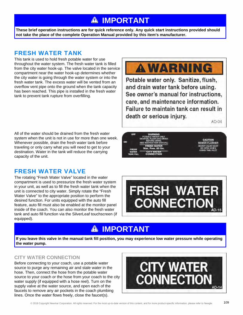
IMPORTANTThese brief operation instructions are for quick reference only. Any quick start instructions provided shouldnot take the place of the complete Operation Manual provided by this item's manufacturer.
FRESH WATER TANKThis tank is used to hold fresh potable water for usethroughout the water system. The fresh water tank is filledfrom the city water hook-up. The valve located in the servicecompartment near the water hook-up determines whetherthe city water is going through the water system or into thefresh water tank. The excess water will be vented from anoverflow vent pipe onto the ground when the tank capacityhas been reached. This pipe is installed in the fresh watertank to prevent tank rupture from overfilling.
All of the water should be drained from the fresh watersystem when the unit is not in use for more than one week.Whenever possible, drain the fresh water tank beforetraveling or only carry what you will need to get to yourdestination. Water in the tank will reduce the carryingcapacity of the unit.
FRESH WATER VALVEThe rotating “Fresh Water Valve” located in the watercompartment is used to pressurize the fresh water systemin your unit, as well as to fill the fresh water tank when theunit is connected to city water. Simply rotate the “FreshWater Valve” to the appropriate position to perform thedesired function. For units equipped with the auto fillfeature, auto fill must also be enabled at the monitor panelinside of the coach. You can also monitor the fresh watertank and auto fill function via the SilverLeaf touchscreen (ifequipped).
IMPORTANTIf you leave this valve in the manual tank fill position, you may experience low water pressure while operatingthe water pump.
CITY WATER CONNECTIONBefore connecting to your coach, use a potable watersource to purge any remaining air and stale water in thehose. Then, connect the hose from the potable watersource to your coach or the hose from your coach to the citywater supply (if equipped with a hose reel). Turn on thesupply valve at the water source, and open each of thefaucets to remove any air pockets in the coach plumbinglines. Once the water flows freely, close the faucet(s).
© 2018 Copyright Newmar Corporation. All rights reserved. For the most up-to-date version of this content, and for more product-specific information, please refer to Newgle. 109

The water pump is used to pressurize the fresh water system when the unit is not connected to city water. The city watersupply is under pressure, so the water pump is not necessary while you are connected to city water. Once the city waterfill valve is not in the manual fill position, the water is supplied to the fresh water system components, including the hotwater heater and faucets.To disconnect from the city water supply, close the valve from water supply, remove the hose from the city water supply,and store it in the water compartment.
FRESH WATER VALVE EXAMPLES
IMPORTANTUse a water hose manufactured and labeled for potable water to ensure that the hose will not alter the taste ofthe water.
LOW POINT DRAINSLow point drains are normally located in the water compartment and are marked "Low Point Drains." Some valves aremounted in the water control panel and others are placed close to the water compartment and marked with a stickernearby.
© 2018 Copyright Newmar Corporation. All rights reserved. For the most up-to-date version of this content, and for more product-specific information, please refer to Newgle. 110

LOW POINT DRAIN CONFIGURATION EXAMPLES
FRESH WATER TANK DRAINSFresh water tank drains are located a few inches in front of or beside the fresh water tank and are connected to the freshtank with a 1/2" or 1" water line.
FRESH WATER TANK DRAIN CONFIGURATION EXAMPLES
© 2018 Copyright Newmar Corporation. All rights reserved. For the most up-to-date version of this content, and for more product-specific information, please refer to Newgle. 111
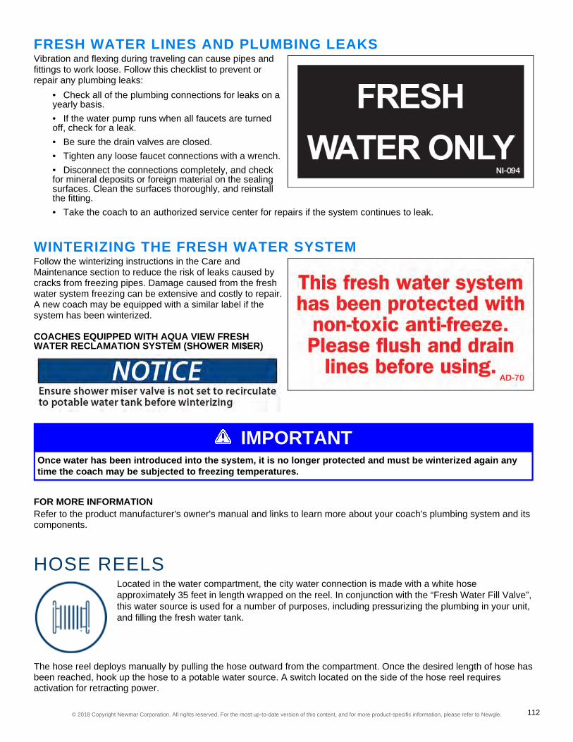
FRESH WATER LINES AND PLUMBING LEAKSVibration and flexing during traveling can cause pipes andfittings to work loose. Follow this checklist to prevent orrepair any plumbing leaks:
• Check all of the plumbing connections for leaks on ayearly basis.• If the water pump runs when all faucets are turnedoff, check for a leak.• Be sure the drain valves are closed.• Tighten any loose faucet connections with a wrench.• Disconnect the connections completely, and checkfor mineral deposits or foreign material on the sealingsurfaces. Clean the surfaces thoroughly, and reinstallthe fitting.• Take the coach to an authorized service center for repairs if the system continues to leak.
WINTERIZING THE FRESH WATER SYSTEMFollow the winterizing instructions in the Care andMaintenance section to reduce the risk of leaks caused bycracks from freezing pipes. Damage caused from the freshwater system freezing can be extensive and costly to repair.A new coach may be equipped with a similar label if thesystem has been winterized.
COACHES EQUIPPED WITH AQUA VIEW FRESHWATER RECLAMATION SYSTEM (SHOWER MI$ER)
IMPORTANTOnce water has been introduced into the system, it is no longer protected and must be winterized again anytime the coach may be subjected to freezing temperatures.
FOR MORE INFORMATIONRefer to the product manufacturer's owner's manual and links to learn more about your coach's plumbing system and itscomponents.
HOSE REELSLocated in the water compartment, the city water connection is made with a white hoseapproximately 35 feet in length wrapped on the reel. In conjunction with the “Fresh Water Fill Valve”,this water source is used for a number of purposes, including pressurizing the plumbing in your unit,and filling the fresh water tank.
The hose reel deploys manually by pulling the hose outward from the compartment. Once the desired length of hose hasbeen reached, hook up the hose to a potable water source. A switch located on the side of the hose reel requiresactivation for retracting power.
© 2018 Copyright Newmar Corporation. All rights reserved. For the most up-to-date version of this content, and for more product-specific information, please refer to Newgle. 112

FOR MORE INFORMATIONRefer to the product manufacturer's owner's manual and links to learn more about your coach's hose reels.
POWER WASHERS, SPRAYERS, AND EXTERIORSHOWERS
An optional power washer provides the convenience of high water pressure for the tougher cleaningjobs, such as driveways, outdoor equipment, patios, and so much more. The exterior shower allowsyou to rinse off sand or grass, muddy shoes, or bathe your pet outside of your coach.
POWER WASHERIf your coach is equipped with a power washer, make sure the water supply is supplying pressurized water to theequipment with the desired attachment.
IMPORTANTUse caution when using high pressure water.
EXTERIOR SHOWERAn exterior shower located on the driver side may be an optional feature on your coach. The faucet operates just as itwould in your kitchen or bathroom. When finished using the exterior shower, shut off both the hot and cold valves. Donot simply shut off the valve on the shower head itself, as it may cause hot and cold water to mix at the exterior showerand could allow drastic changes in water temperature throughout the coach.
FOR MORE INFORMATIONRefer to the product manufacturer's owner's manual and links to learn more about your coach's power washers andsprayers.
SINKSNewmar installs a wide range of sinks in our coaches, including stainless steel, solid surface, glassand others, as well as drop-in, undermount, and bowl-type installations to achieve different stylesand aesthetic designs.
P-TRAPSEach of the sink drains have a water trap to prevent holding tank odors from entering the coach. These traps must havewater in them in order to trap the odors. While traveling, the water may splash out of the sink drains. While stored, thewater may evaporate, allowing an odor to enter the coach. If this occurs, run water from the faucet into the drain,allowing water to fill the trap. Some coach models with a rear shower may have waterless traps in lieu of conventional P-traps.
CARE AND MAINTENANCEUse care when cleaning to prevent scratching the surfaces of your sinks. Wash with a mild detergent and a soft cloth.
© 2018 Copyright Newmar Corporation. All rights reserved. For the most up-to-date version of this content, and for more product-specific information, please refer to Newgle. 113
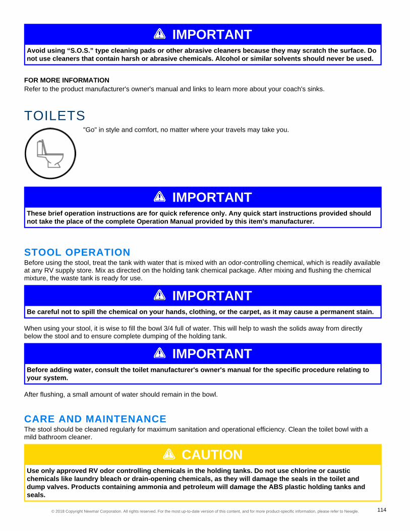
IMPORTANTAvoid using “S.O.S.” type cleaning pads or other abrasive cleaners because they may scratch the surface. Donot use cleaners that contain harsh or abrasive chemicals. Alcohol or similar solvents should never be used.
FOR MORE INFORMATIONRefer to the product manufacturer's owner's manual and links to learn more about your coach's sinks.
TOILETS"Go" in style and comfort, no matter where your travels may take you.
IMPORTANTThese brief operation instructions are for quick reference only. Any quick start instructions provided shouldnot take the place of the complete Operation Manual provided by this item's manufacturer.
STOOL OPERATIONBefore using the stool, treat the tank with water that is mixed with an odor-controlling chemical, which is readily availableat any RV supply store. Mix as directed on the holding tank chemical package. After mixing and flushing the chemicalmixture, the waste tank is ready for use.
IMPORTANTBe careful not to spill the chemical on your hands, clothing, or the carpet, as it may cause a permanent stain.
When using your stool, it is wise to fill the bowl 3/4 full of water. This will help to wash the solids away from directlybelow the stool and to ensure complete dumping of the holding tank.
IMPORTANTBefore adding water, consult the toilet manufacturer's owner's manual for the specific procedure relating toyour system.
After flushing, a small amount of water should remain in the bowl.
CARE AND MAINTENANCEThe stool should be cleaned regularly for maximum sanitation and operational efficiency. Clean the toilet bowl with amild bathroom cleaner.
CAUTIONUse only approved RV odor controlling chemicals in the holding tanks. Do not use chlorine or causticchemicals like laundry bleach or drain-opening chemicals, as they will damage the seals in the toilet anddump valves. Products containing ammonia and petroleum will damage the ABS plastic holding tanks andseals.
© 2018 Copyright Newmar Corporation. All rights reserved. For the most up-to-date version of this content, and for more product-specific information, please refer to Newgle. 114
WARNINGOn coaches equipped with a macerator or macerator toilet(s), do not flush diaper wipes, feminine hygieneproducts, or any other products that would not be easily liquified. Also avoid using holding tank deodorantcapsules, as they may cause damage to the macerator. Damage resulting from flushing any materials orobjects other than organic waste and toilet paper are not warrantable repairs.
FOR MORE INFORMATIONRefer to the product manufacturer's owner's manual and links to learn more about your coach's toilets.
TUBS AND SHOWER ENCLOSURESBased on the floorplan, your coach may be equipped with a shower and/or tub in the rear or midbath.
P-TRAPS AND WATERLESSTRAPSThe shower drain has a water trap to prevent holding tankodors from entering the coach. These traps must havewater in them in order to trap the odors. While traveling, thewater may splash out of the shower drain. While stored, thewater may evaporate, allowing an odor to enter the coach. Ifthis occurs, run water from the faucet into the drain,allowing water to fill the trap.Some coach models with a rear shower may have waterless traps in lieu of conventional p-traps.
CARE AND MAINTENANCEMake sure doors are closed and latched or locked prior to travel. Wipe down the tub and shower walls with a milddetergent and a soft cloth, as well as any glass enclosures after use to avoid soap scum and hard water deposits.
IMPORTANTAvoid using “S.O.S.” type cleaning pads or other abrasive cleaners because they may scratch the surface. Donot use cleaners that contain harsh or abrasive chemicals. Alcohol or similar solvents should never be used.
When winterizing your coach, clean up any remaining antifreeze in your tub or shower, as it may cause staining.
IMPORTANTIf standing water occurs in your shower, do not attempt to unplug or open the drain with a coat hanger or asewer snake. Before taking your coach to a service center, try leveling your coach so that the rear is raisedslightly higher than the front. This may correct the condition and prevent drain-cleaning or a service repair. Ifthis does not correct the issue, Newmar recommends taking your coach to a service center for drain-cleaningor repair.
FOR MORE INFORMATIONRefer to the product manufacturer's owner's manual and links to learn more about your coach's tubs and showers.
© 2018 Copyright Newmar Corporation. All rights reserved. For the most up-to-date version of this content, and for more product-specific information, please refer to Newgle. 115
WASTE WATER SYSTEMThere are two separate waste systems: the gray tank system and the black tank system. Each tankhas its own control valve, and both tanks drain through the sewer drain hose.
IMPORTANTThese brief operation instructions are for quick reference only. Any quick start instructions provided shouldnot take the place of the complete Operation Manual provided by this item's manufacturer.
WASTE WATER HOLDING TANKSThe waste drainage system was designed to provideadequate and safe storage and/or disposal of wastematerials. The drainage system uses plastic piping andfittings connected to the sinks, toilet, and holding tanks toprovide for their drainage to an outside termination. The unitshould be reasonably level for best operation of the system.
GRAY TANKThe gray water holding tank is located in the underbelly ofthe unit. It is primarily used for the drainage from the kitchenand bath sinks, and the shower.
CAUTIONThe gray tank valve must be in the open position when operating the optional washing machine.
BLACK TANKThe black water holding tank is generally for sewage wastefrom the stool and is located directly beneath the toilet onstandard flushing toilets. Before using the stool, you willneed to treat the tank with water that is mixed with an odor-controlling chemical, which is readily available at any RVsupply store.
IMPORTANTBe careful not to spill the chemical on your hands, clothing, or the carpet as it may cause a permanent stain.
CAUTIONUse only approved RV odor-controlling chemicals in the holding tanks. Products containing ammonia andpetroleum will damage the ABS plastic holding tanks and seals.
© 2018 Copyright Newmar Corporation. All rights reserved. For the most up-to-date version of this content, and for more product-specific information, please refer to Newgle. 116
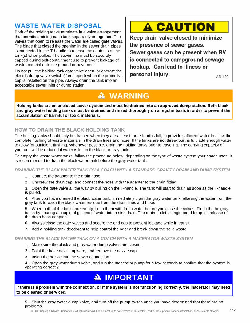
WASTE WATER DISPOSALBoth of the holding tanks terminate in a valve arrangementthat permits draining each tank separately or together. Thevalves that open to release the water are called gate valves.The blade that closed the opening in the sewer drain pipesis connected to the T-handle to release the contents of thetank(s) when pulled. The sewer line must be securelycapped during self-containment use to prevent leakage ofwaste material onto the ground or pavement.Do not pull the holding tank gate valve open, or operate theelectric dump valve switch (if equipped) when the protectivecap is installed on the pipe. Always drain the tank into anacceptable sewer inlet or dump station.
WARNINGHolding tanks are an enclosed sewer system and must be drained into an approved dump station. Both blackand gray water holding tanks must be drained and rinsed thoroughly on a regular basis in order to prevent theaccumulation of harmful or toxic materials.
HOW TO DRAIN THE BLACK HOLDING TANKThe holding tanks should only be drained when they are at least three-fourths full, to provide sufficient water to allow thecomplete flushing of waste materials in the drain lines and hose. If the tanks are not three-fourths full, add enough waterto allow for sufficient flushing. Whenever possible, drain the holding tanks prior to traveling. The carrying capacity ofyour unit will be reduced if water is left in the black or gray tanks.To empty the waste water tanks, follow the procedure below, depending on the type of waste system your coach uses. Itis recommended to drain the black water tank before the gray water tank.
DRAINING THE BLACK WATER TANK ON A COACH WITH A STANDARD GRAVITY DRAIN AND DUMP SYSTEM1. Connect the adapter to the drain hose.2. Unscrew the drain cap, and connect the hose with the adapter to the drain fitting.3. Open the gate valve all the way by pulling on the T-handle. The tank will start to drain as soon as the T-handleis pulled.4. After you have drained the black water tank, immediately drain the gray water tank, allowing the water from thegray tank to wash the black water residue from the drain lines and hose.5. When both of the tanks are empty, flush them with fresh water before you close the valves. Flush the he graytanks by pouring a couple of gallons of water into a sink drain. The drain outlet is engineered for quick release ofthe drain hose adapter.6. Always close the gate valves and secure the end cap to prevent leakage while in transit.7. Add a holding tank deodorant to help control the odor and break down the solid waste.
DRAINING THE BLACK WATER TANK ON A COACH WITH A MACERATOR WASTE SYSTEM1. Make sure the black and gray water dump valves are closed.2. Point the hose nozzle upward, and remove the nozzle cap.3. Insert the nozzle into the sewer connection.4. Open the gray water dump valve, and run the macerator pump for a few seconds to confirm that the system isoperating correctly.
IMPORTANTIf there is a problem with the connection, or if the system is not functioning correctly, the macerator may needto be cleaned or serviced.
5. Shut the gray water dump valve, and turn off the pump switch once you have determined that there are noproblems.
© 2018 Copyright Newmar Corporation. All rights reserved. For the most up-to-date version of this content, and for more product-specific information, please refer to Newgle. 117

6. Open the black water dump valve, and turn on the macerator pump switch.7. Monitor the tank as it empties. The pump with run louder when the tank is empty.8. Turn off the pump switch once the tank is empty.9. Flush the black tank, and operate the macerator while it is flushing.10. Turn off the flush system, then turn off the macerator.11. Close the black water dump valve.12. Add tank chemicals and the amount of water recommended by the chemical manufacturer.13. Drain the gray tank next to help flush out the macerator and sewer hose.
HOW TO DRAIN THE GRAY WATER TANK1. Open the gray water dump valve.2. Turn on the pump switch.3. Monitor the tank as it empties. The pump will run louder when the tank is empty.4. Turn off the pump switch once the tank is empty.5. Close the gray water dump valve.6. Place the cap on the hose and store it.7. Add tank chemicals and the amount of water recommended by the chemical manufacturer.
HOLDING TANK RINSE - NO FUSS FLUSHThis unit may be equipped with a flushing system for theholding tanks. When draining your sewer tank, attach awater hose to the sewer spray hookup. After the tank isdrained, leave the gate valve open, and open the watervalve to allow water to spray inside the sewage tank. Allowthe water to rinse the tank for a minimum of three tofive minutes to ensure it is clean. This should flush the inside of the tank of any debris that may be left inside.
Next, disconnect the freshwater hose and close the gate valve. If there are any solids still left inside the tank, fill thesewage tank with approximately ten gallons of water through the stool. As you travel, the agitation of the water shouldhelp liquefy any solids left in the tank. You can dump the sewage tank again at your next destination.
IMPORTANTAlways drain the sewage tank prior to rinsing. Never rinse a sewage tank that is full. The sewage drain mustbe open while rinsing the sewage tank, and the drain hose must be positioned to drain into an approvedsewage dump station. Failure to open the valve will cause the sewage tank to fill with water, and can causedamage to your plumbing and interior.
© 2018 Copyright Newmar Corporation. All rights reserved. For the most up-to-date version of this content, and for more product-specific information, please refer to Newgle. 118

CAUTIONDo not use the same hose for the No Fuss Flush that is used for filling the fresh water tank. The gate valve tothe sewage tank must be in the OPEN position while rinsing with the No Fuss Flush system.
P-TRAPSEach of the sink drains, the shower drain, and the washingmachine drain (if equipped) has a water trap to preventholding tank odors from entering the coach. These trapsmust have water in them in order to trap the odors. Whiletraveling, the water may splash out of the sink and showerdrains. While stored, the water may evaporate, allowing anodor to enter the coach. If this occurs, run water from thefaucet into the drain, allowing water to fill the trap. Somecoach models with a rear shower may have waterless trapsin lieu of conventional p-traps
IMPORTANTIf standing water occurs in your shower, do not attempt to unplug or open the drain with a coat hanger or asewer snake. Before taking your coach to a service center, try leveling your coach so that the rear is raisedslightly higher than the front. This may correct the condition and prevent drain-cleaning or a service repair.
CAMPING WITH SEWER HOOK-UPWhen camping at parks with sewer hook-up, it is important to keep the black water holding tank gate valve closed at alltimes, except when dumping. The gray tank can be kept open while hooked to a sewer connection, but the black watertank must be kept closed. This is done so that an ample supply of liquid remains in the tank to provide a smooth flowthrough the gate and drain valve when dumping. Sufficient liquid in the tank causes a swirling action that should takeany accumulated solid wastes with it. Accumulation of solid wastes in the black water tank can be avoided by keepingthe gate valve closed when connected to the sewer hook-up. If the valve is left open, solid wastes may accumulate inthe tank. This may eventually result in costly repairs.
FOR MORE INFORMATIONRefer to the product manufacturer's owner's manual and links to learn more about your coach's waste water system.
WATER HEATERSKeep your water warm for cooking, bathing, and cleaning in your coach.
DIRECT SPARK IGNITION WATER HEATERS
IMPORTANTBefore operating the water heater, the tank must be filled with water.
© 2018 Copyright Newmar Corporation. All rights reserved. For the most up-to-date version of this content, and for more product-specific information, please refer to Newgle. 119

WARNINGDo not store any combustible materials or liquids near or adjacent to the water heater.
HOW TO OPERATE A WATER HEATER ON LP1. Make sure the water heater is full of water and is not bypassed.2. Turn on the gas valve on the LP tank.3. Prior to activating the water heater, smell for any gas odors, as any present fumes may create a spark andflame.4. Turn on the switch to light the burner. The control board will attempt three times to ignite the LP at the burner.After three attempts, the red indicator light at the switch will illuminate.5. If lockout occurs, turn the switch off, and wait several seconds before turning it back on. It will make three moreattempts to light the burner.6. On initial startup, it may take a few cycles to purge the LP lines.7. If the water heater continually fails to light, refer to the Operator's Manual for your specific water heater.
PROPANE DISTRIBUTION LINES
WARNINGThe primary gas supply manifold is a black steel pipe running the length of the unit. Most secondary linesleading to the gas appliances are made of copper tubing with flare fittings. If any of these lines rupture, do notattempt to splice them. Always run a new line. Gas distribution work must be performed by an authorizedservice technician. When removing or servicing any gas appliance, close the main gas valve on the propanetank to prevent dangerous gas leakage that could result in an explosion and possible serious injury. If a gasleak is suspected, have the system inspected and repaired by a qualified service technician as soon aspossible.
HOW TO OPERATE A WATER HEATER WITH AN ELECTRIC ELEMENT ON 120 VOLTPOWER
1. Check for the proper voltage supply (120 Volts).2. Make sure the water heater is full of water and is not bypassed.3. Turn on the switch to the electric element. The water heater will control the temperature.4. If the water heater fails to heat, refer to the Operator's Manual for your specific water heater.
PRESSURE RELIEF VALVEThe temperature and pressure relief valve is located on the exterior of the water heater. It is designed to open if thetemperature of the water within the heater reaches 210° F, or if the water pressure in the heater reaches 150 pounds.Recreational vehicle water systems are closed systems, and during the water heating cycle the pressure build-up in thewater system may reach 150 pounds. When this pressure is reached, the pressure relief valve will open and water willdrip from the valve. This dripping will continue until the pressure is reduced below 150 pounds, and the valve closes.This condition is normal and does not indicate a defective relief valve.
WARNINGDo not plug the relief valve under any circumstances.
WATER HEATER BY-PASS SYSTEMThe water heater by-pass valve is located near the water heater. By closing the water heater supply valve and openingthe by-pass valve, you can divert water away from the water heater. Using the by-pass while winterizing your unit willkeep antifreeze out of the water heater. Draining the water heater during winterizing is required.
© 2018 Copyright Newmar Corporation. All rights reserved. For the most up-to-date version of this content, and for more product-specific information, please refer to Newgle. 120

WATER HEATER STORAGEWhen storing your coach for the winter months, the water heater must be drained to prevent damage from freezing.
1. Turn off all electrical power and the propane supply to the water heater.2. Turn off the water pump.3. Open both the hot and cold water faucets to relieve the pressure in the lines and water heater.4. Open the drain on the water heater (if equipped), or remove the drain plug or anode rod.5. Drain the entire water system and follow the winterization instructions provided in Newgle.
When preparing the coach for use after it has been stored, make certain the water system, including the water heater,has been filled before restoring electric and the propane supply.
FOR MORE INFORMATIONRefer to the product manufacturer's owner's manual and links to learn more about your coach's water heater.
SUBURBAN WATER HEATERS
IMPORTANTThese brief operation instructions are for quick reference only. Any quick start instructions provided shouldnot take the place of the complete Operation Manual provided by this item's manufacturer.
To turn on and off the propane portion of the water tank,press the rocker switch on the Suburban water heater panelin the overhead compartment. The red reset button willilluminate if the water heater fails to ignite.For coaches equipped with electric water heater elements,turn it on and off using the rocker switch on the oppositepanel.
WATER PUMPSThe water pump is self-priming and totally automatic, operating on demand whenever water isrequired. The water pump is used to pressurize the fresh water system when the unit is notconnected to city water. When the water pump switch is turned on, the water pump will buildpressure in the system, and will shut off as soon as the system is correctly pressurized. When afaucet is opened, the pump will turn on and operate as necessary to maintain the preset pressure inthe system.
IMPORTANTThese brief operation instructions are for quick reference only. Any quick start instructions provided shouldnot take the place of the complete Operation Manual provided by this item's manufacturer.
OPERATING INSTRUCTIONS1. Fill or partially fill the fresh water supply tank.2. Open the kitchen and bathroom faucets.
© 2018 Copyright Newmar Corporation. All rights reserved. For the most up-to-date version of this content, and for more product-specific information, please refer to Newgle. 121
3. Turn the water pump switch on and allow the water to fill the water line and the hot water heater. The switch tothis pump may be located in the bathroom.4. Close each faucet after it delivers a steady stream of water (close the cold water first). Leave the hot waterfaucets on until they also deliver a steady stream of water. This will ensure that the water heater is filled with water.5. The water pump should stop running once all faucets are closed.6. The pump is now ready for automatic operation. The pump will run when a faucet is opened and stop when afaucet is closed.
CAUTIONNever allow the pump to run for long periods of time without water in the supply tank, as pump damage orblown fuses may result.
TROUBLESHOOTINGIf water doesn’t flow when a faucet is turned on while using the demand system, use the following troubleshooting tips.
1. If the pump is running, but there is no water:• Fill the tank.• Clear the water line to the pump.• Rotate the city water / tank fill valve to the correct position.
2. If the pump isn't running:• Check the pump switch.• Check the 12 Volt fuses.• Check the electrical connections.• Check the battery.
CARE AND MAINTENANCEAll of the water should be drained from the fresh water system when the unit is not in use for more than one week.
FOR MORE INFORMATIONRefer to the product manufacturer's owner's manual and links to learn more about your coach's water pump.
© 2018 Copyright Newmar Corporation. All rights reserved. For the most up-to-date version of this content, and for more product-specific information, please refer to Newgle. 122

IMPORTANTIn the unlikely occasion that the slideout trim hasinadequate clearances, try leveling or repositioningthe coach and rechecking the clearances beforeextending the slideout.
SLIDEOUTSNewmar pushed the RV industry forward by introducing the first flat floor slideouts. We continue tolead today with our patented flat floor slideout designs. The same insight and experience that helpedus improve slideout functionality has also helped us improve slideout quality. This category providesinformation about your flat floor, bedroom, kitchen, wardrobe, and full wall slideouts. Under eachsub-category, you will have access to information about each slideout in your Newmar coach.
The following warnings may be posted in the coach overhead compartment, in a cabinet, or on the wall next to thecorresponding slideouts.
WARNINGBefore operating any slideout, read and follow the posted warning labels.
IMPORTANTClean the slideout rollers under the floor regularly, as dirt may adhere to the rubber coating on the rollers andcause damage to the flooring. Debris on the rollers may leave indentations or scratches on the flooring, andsuch damage does not warrant flooring replacement and is not covered under warranty.
EXTENDING THE SLIDEOUTS1. Park the coach on a reasonably level campsite.2. Leave the coach at ride-height with air in the air bags (if equipped with airsuspension) or on normal suspension (coaches without air suspension).3. Plug the coach into shore power (if available) or start the generator toincrease the voltage for better slideout operation.4. For a full wall slideout, visually inspect the front vertical trim for adequateclearance. The spacing should look even from top to bottom. (See image.)5. Verify that the path of the slideout is unobstructed and free from anysurrounding objects, both inside and outside of the coach.6. Once the appropriate conditions are met, follow the operating instructionsposted in your coach to extend the slideouts.7. Deploy the leveling jacks.
RETRACTING THE SLIDEOUTS1. Retract the leveling jacks.2. Start the coach.3. Allow the coach air suspension to fill and return to ride height (units without air suspension will return to normalsuspension).4. Turn the engine off.5. For a full wall slideout, visually inspect the front vertical trim for adequate clearance. The spacing should lookeven from top to bottom. (See image for reference.)
© 2018 Copyright Newmar Corporation. All rights reserved. For the most up-to-date version of this content, and for more product-specific information, please refer to Newgle. 123

6. Verify that the path of the slideout is unobstructed and free from any surrounding objects, both inside andoutside of the coach. This includes any water or debris that may have collected on the slideout roof or the topperawning.
IMPORTANTDebris left on the roof or topper may prevent the slideout from sealing properly when retracted, as well asprevent the mechanical lock arms from closing properly when the slideout is extended.
7. Retract the slideouts.8. Inspect all slideouts for complete retraction.9. If the coach is equipped with manual lock arms, make sure to lock them.10. Unplug the coach from shore power when you are ready to depart.
IMPORTANTIn the unlikely occasion that the slideout trim has inadequate clearances, try leveling or repositioning thecoach and rechecking the clearances before retracting the slideout.
ELECTRIC BEDROOM SLIDEOUTSThe operating switch for the bedroom slideout is usually located on the bedroom wall. If there is afull wall slideout on the driver side of the coach, the switch may be located on the wall thatseparates the bedroom from the living room.
ELECTRIC BEDROOM SLIDEOUT OPERATIONIn order to operate the bedroom slideout with the required voltage levels, batteries should be fully charged, thegenerator should be powered on, or the coach should be connected to shore power. This maintains the voltage levelsrequired to operate the slideouts.
IGNITION LOCKOUTDue to the slideout safety feature commonly referred to as ‘ignition lockout’, the operation of your slideout will beprohibited under one or more of the following conditions:
• Partial slideout operation is prohibited when the key is in the accessory or run position, allowing the slideout toretract, but not extend.• Total slideout operation is prohibited when the module receives an ignition signal when the key is in the runposition. However, the slideout will operate in the accessory position, because it does not receive an ignition signal.• Total slideout operation is prohibited when the ignition switch is in either the accessory or run position.• Total slideout operation is prohibited when the park brake is not set.• The disabling of the slideout is based on the individual slideout control module programming and the ignitionswitch circuit signal.
Once the appropriate safety feature conditions are met and the path of the slideout is unobstructed both inside andoutside of the coach, follow the operating instructions posted in your coach like the examples below.
IMPORTANTRead entire slideout room instructions posted in your coach before extending or retracting the slideout.
© 2018 Copyright Newmar Corporation. All rights reserved. For the most up-to-date version of this content, and for more product-specific information, please refer to Newgle. 124

ELECTRIC BEDROOM SLIDEOUT MAINTENANCEElectric slideout drive mechanisms do not require lubrication as part of the scheduled maintenance. Some noise isnormal during extension and retraction from the various moving parts and seals.
IMPORTANTNewmar does not recommend the use of grease, silicone, or WD-40 on the slideout tubes or chains, as theseproducts tend to collect dirt and dust.
If lubrication is desired, Newmar recommends using a light coat of LPS 1 Greaseless Lubricant, which provides a drythin lubrication film that is resistant to dirt and dust buildup.
HOW TO MANUALLY RETRACT AN ELECTRICBEDROOM SLIDEOUTProvides three possible methods for manually retracting a bedroom slideout if it will not retract on its own.
IMPORTANTPrior to proceeding with a manual retraction procedure, make sure the ignition key is in the off position andthe park brake is set. Then, try retracting the slideout again, as some controllers require the ignition to be off,and others require the park brake to be set.
WARNINGThe manual retraction procedures are for emergency use only. These procedures bypass all normal safetyfeatures. It is the responsibility of the person(s) performing the procedure to watch for moving parts andpinch points in order to avoid injury.
PROCEDURE 1This method requires the motor and gear box to be operational. This procedure bypasses the slide controller, switch,and the wiring. If battery power is unavailable or the motor/gear box is inoperable, move to procedure two.
© 2018 Copyright Newmar Corporation. All rights reserved. For the most up-to-date version of this content, and for more product-specific information, please refer to Newgle. 125

IMPORTANTThis procedure can be performed on any single motor electric slideout.
1. Disconnect the red and black wires connected to the motor.2. Using the the wires attached to the motor, connect to a 12 volt cordless battery to retract the slideout. If thewire polarity is reversed, the slideout will extend instead of retract.
IMPORTANTIf the slideout motor has a brake installed, you must also hook one brake wire to the battery with the redslideout motor wire and one with the black slideout motor wire.
1. Disconnect the wire(s) from the cordless battery pack.
PROCEDURE 2Determine which slideout setup your coach utilizes, and follow the steps below pertaining to your specific setup.
CONVENTIONAL BEDROOM SLIDEOUT SETUP
IMPORTANTThis procedure can be performed on coaches with a slideout motor located under the bed frame.
This method is the fastest one if the motor or gears fail, as it does not requirebattery power. However, this method requires a significant amount of manpower topush in the slideout.
1. Open the lid of the bed box.2. Loosen the trantorque bushing.3. Push the room into the retracted position.4. Retighten the trantorque bushing.5. Take the coach to an authorized service center for diagnosis and repair.
-or-1. Open the lid of the bed box.2. Loosen the trantorque bushing.3. Turn the shaft with a wrench until the slideout reaches the retractedposition. Make sure you do not damage the shaft with the wrench.4. Retighten the trantorque bushing.5. Take the coach to an authorized service center for diagnosis and repair.
© 2018 Copyright Newmar Corporation. All rights reserved. For the most up-to-date version of this content, and for more product-specific information, please refer to Newgle. 126
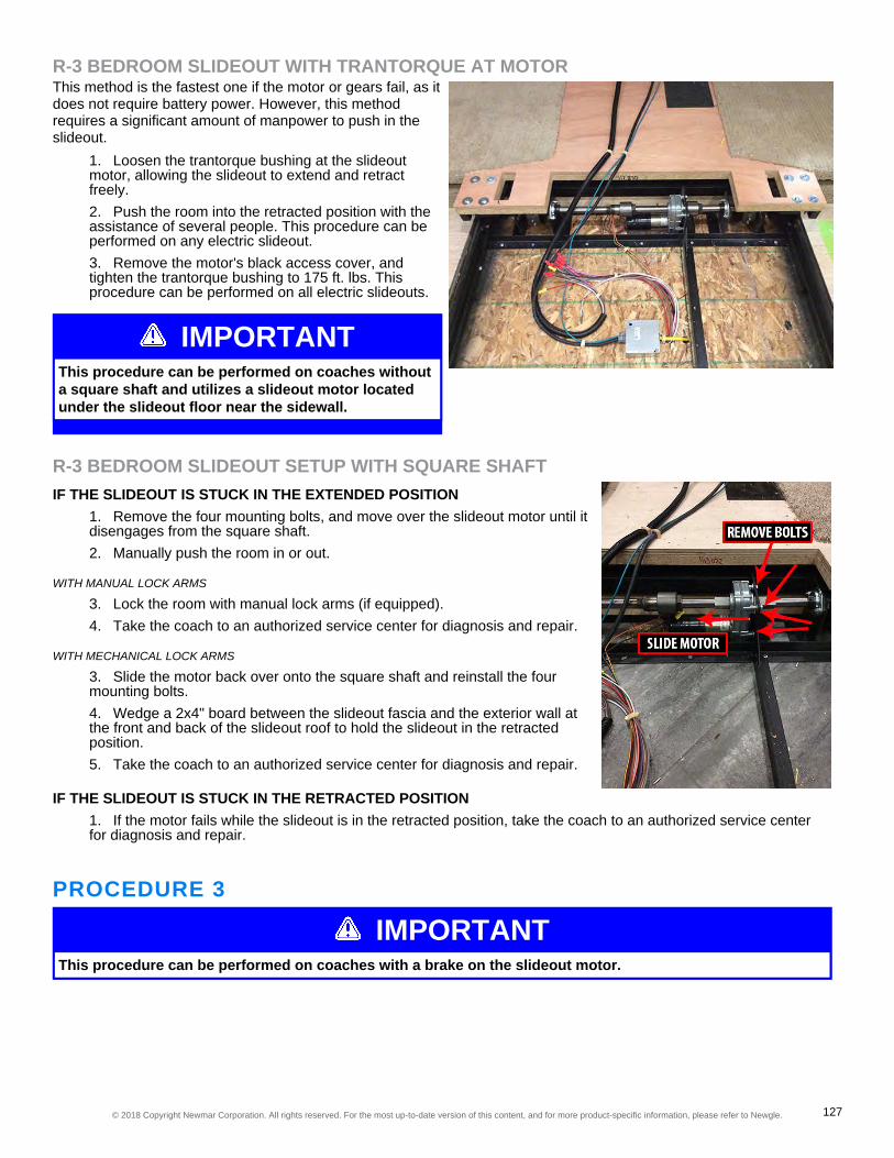
IMPORTANTThis procedure can be performed on coaches withouta square shaft and utilizes a slideout motor locatedunder the slideout floor near the sidewall.
R-3 BEDROOM SLIDEOUT WITH TRANTORQUE AT MOTORThis method is the fastest one if the motor or gears fail, as itdoes not require battery power. However, this methodrequires a significant amount of manpower to push in theslideout.
1. Loosen the trantorque bushing at the slideoutmotor, allowing the slideout to extend and retractfreely.2. Push the room into the retracted position with theassistance of several people. This procedure can beperformed on any electric slideout.3. Remove the motor's black access cover, andtighten the trantorque bushing to 175 ft. lbs. Thisprocedure can be performed on all electric slideouts.
R-3 BEDROOM SLIDEOUT SETUP WITH SQUARE SHAFTIF THE SLIDEOUT IS STUCK IN THE EXTENDED POSITION
1. Remove the four mounting bolts, and move over the slideout motor until itdisengages from the square shaft.2. Manually push the room in or out.
WITH MANUAL LOCK ARMS
3. Lock the room with manual lock arms (if equipped).4. Take the coach to an authorized service center for diagnosis and repair.
WITH MECHANICAL LOCK ARMS
3. Slide the motor back over onto the square shaft and reinstall the fourmounting bolts.4. Wedge a 2x4" board between the slideout fascia and the exterior wall atthe front and back of the slideout roof to hold the slideout in the retractedposition.5. Take the coach to an authorized service center for diagnosis and repair.
IF THE SLIDEOUT IS STUCK IN THE RETRACTED POSITION1. If the motor fails while the slideout is in the retracted position, take the coach to an authorized service centerfor diagnosis and repair.
PROCEDURE 3
IMPORTANTThis procedure can be performed on coaches with a brake on the slideout motor.
© 2018 Copyright Newmar Corporation. All rights reserved. For the most up-to-date version of this content, and for more product-specific information, please refer to Newgle. 127

IMPORTANTMake sure you do not damage portions of the shaftthat will slide through the motor, trantorque, bearing,and cog wheels.
Only a few tools are necessary to complete this procedure;however, it requires the gear box to be operational. Followthe steps to manually retract the slideout by removing thebrake and turning the shaft.
1. First, locate the strap that secures the rubber booton the outside of the motor.2. Remove the strap, and pull off the rubber boot,removing it from the motor.
3. Remove the four screws from under the rubber boot on thebrake.4. Once the brake is removed, use a wrench to turn the shaft toretract the slideout.
5. After the slideout is fully retracted, reinstall the brake.
NOTICEDepending on the year, model, and floorplan of the coach, the exact slideout motor(s) location may vary.Generally, they may be accessed from under the bed.
ELECTRIC FLAT FLOOR SLIDEOUTSThe operating switch for the flat floor slideout is usually located in the overhead cabinet above thedriver or passenger chair or the overhead cabinet above the entrance door.
ELECTRIC FLAT FLOOR SLIDEOUT OPERATIONIn order to operate the flat floor slideout with the required voltage levels, batteries should be fully charged, the generatorshould be powered on, or the coach should be connected to shore power. This maintains the voltage levels required tooperate the slideouts.
© 2018 Copyright Newmar Corporation. All rights reserved. For the most up-to-date version of this content, and for more product-specific information, please refer to Newgle. 128

IGNITION LOCKOUTDue to the slideout safety feature commonly referred to as ‘ignition lockout’, the operation of your slideout will beprohibited under one or more of the following conditions:
• Partial slideout operation is prohibited when the key is in the accessory or run position, allowing the slideout toretract, but not extend.• Total slideout operation is prohibited when the module receives an ignition signal when the key is in the runposition. However, the slideout will operate in the accessory position, because it does not receive an ignition signal.• Total slideout operation is prohibited when the ignition switch is in either the accessory or run position.• Total slideout operation is prohibited when the park brake is not set.• The disabling of the slideout is based on the individual slideout control module programming and the ignitionswitch circuit signal.
Once the appropriate safety feature conditions are met and the path of the slideout is unobstructed both inside andoutside of the coach, follow the operating instructions posted in your coach.
IMPORTANTRead entire slideout room instructions posted in your coach before extending or retracting the slideout.
ELECTRIC FLAT FLOOR SLIDEOUT MAINTENANCEElectric slideout drive mechanisms do not require lubrication as part of the scheduled maintenance. Some noise isnormal during extension and retraction from the various moving parts and seals.
IMPORTANTNewmar does not recommend the use of grease, silicone, or WD-40 on the slideout tubes or chains, as theseproducts tend to collect dirt and dust.
If lubrication is desired, Newmar recommends using a light coat of LPS 1 Greaseless Lubricant, which provides a drythin lubrication film that is resistant to dirt and dust buildup.
HOW TO MANUALLY RETRACT AN ELECTRICFLAT FLOOR SLIDEOUTIf the electric flat floor slideout will not retract on its own, there are three possible methods for retracting it manually.
© 2018 Copyright Newmar Corporation. All rights reserved. For the most up-to-date version of this content, and for more product-specific information, please refer to Newgle. 129

IMPORTANTPrior to proceeding with a manual retraction procedure, make sure the ignition key is in the off position andthe park brake is set. Then, try retracting the slideout again, as some controllers require the ignition to be off,and others require the park brake to be set.
WARNINGThe manual retraction procedures are for emergency use only. These procedures bypass all normal safetyfeatures. It is the responsibility of the person(s) performing the procedure to watch for moving parts andpinch points in order to avoid injury.
MANUAL RETRACTION METHOD 1This method is quick, but requires the motor and gear box to be operational. This procedure bypasses the slidecontroller, switch, and the wiring.
IMPORTANTThis procedure is possible to perform on any single motor electric slideout.
1. Disconnect the red and black wires attached to the motor from the coach wiring.2. Using the the wires attached to the motor, connect to a 12 volt cordless battery to retract the slideout. If thewire polarity is reversed, the slideout will extend instead of retract.
IMPORTANTIf the slideout motor has a brake installed, you must also hook one brake wire to the battery with the redslideout motor wire and one with the black slideout motor wire.
1. Disconnect the wire(s) from the cordless battery pack.2. Take the coach to an authorized service center for diagnosis and repair.
MANUAL RETRACTION - METHOD 2This method requires a significant amount of manpower.
1. Loosen the trantorque bushing at the slideout motor, allowing the slideoutto extend and retract freely.2. Now the room can be pushed in manually with the assistance of severalpeople.3. After the slideout has been pushed in, tighten the trantorque bushing to175 ft. lbs.
© 2018 Copyright Newmar Corporation. All rights reserved. For the most up-to-date version of this content, and for more product-specific information, please refer to Newgle. 130

MANUAL RETRACTION - METHOD 3The third option takes longer; however, only a screw gun orratchet is required. Follow the steps to manually retract theslideout using the gear reduction nuts.
1. First, locate the strap that secures the rubber booton the outside of the motor.
2. Remove the strap, and pull off the rubber boot,removing it from the motor.
3. Remove the four screws from under the rubber boot on thebrake.
© 2018 Copyright Newmar Corporation. All rights reserved. For the most up-to-date version of this content, and for more product-specific information, please refer to Newgle. 131

IMPORTANTScrew guns are recommended due to the majorreduction in the gears. It will take many revolutions ofthe gear reduction nut to retract the slideout.
4. Once the brake is removed, use a screw gun or a ratchet with a 5/8"socket to turn the gear reduction nut to retract the slideout.
4. After the slideout is fully retracted, reinstall the brake.5. Take the coach to an authorized service center for diagnosis and repair.
NOTICEDepending on the year, model, and floorplan of the coach, the exact slideout motor(s) location may vary.Generally, they may be accessed from under the slideout in the compartment area.
ELECTRIC FULL WALL SLIDEOUTSMost electric full wall slideouts extend from the living area to the master bathroom in a Newmarcoach.
ELECTRIC FULL WALL SLIDEOUT OPERATIONIn order to operate the full wall slideout with the required voltage levels, batteries should be fully charged, the generatorshould be powered on, or the coach should be connected to shore power. This maintains the voltage levels required tooperate the slideouts.
IGNITION LOCKOUTDue to the slideout safety feature commonly referred to as ‘ignition lockout’, the operation of your slideout will beprohibited under one or more of the following conditions:
• Partial slideout operation is prohibited when the key is in the accessory or run position, allowing the slideout toretract, but not extend.• Total slideout operation is prohibited when the module receives an ignition signal when the key is in the runposition. However, the slideout will operate in the accessory position, because it does not receive an ignition signal.• Total slideout operation is prohibited when the ignition switch is in either the accessory or run position.• Total slideout operation is prohibited when the park brake is not set.• The disabling of the slideout is based on the individual slideout control module programming and the ignitionswitch circuit signal.
Once the appropriate safety feature conditions are met and the path of the slideout is unobstructed both inside andoutside of the coach, follow the operating instructions posted in your coach.
© 2018 Copyright Newmar Corporation. All rights reserved. For the most up-to-date version of this content, and for more product-specific information, please refer to Newgle. 132

IMPORTANTRead entire slideout room instructions posted in your coach before extending or retracting the slideout.
ELECTRIC FULL WALL SLIDEOUT MAINTENANCEElectric slideout drive mechanisms do not require lubrication as part of the scheduled maintenance. Some noise isnormal during extension and retraction from the various moving parts and seals.
IMPORTANTNewmar does not recommend the use of grease, silicone, or WD-40 on the slideout tubes or chains, as theseproducts tend to collect dirt and dust.
If lubrication is desired, Newmar recommends using a light coat of LPS 1 Greaseless Lubricant, which provides a drythin lubrication film that is resistant to dirt and dust buildup.
ABS TILE PROTECTORSIf your coach is equipped with tile protectors, place them over the tile at each slideout roller. Earlier versions of floorprotectors have a lip at the edge of the tile facing down. Later versions do not have a lip, as they are tapered on one endwith a rubberized back. Place the tapered edge toward the roller with the rubber back against the tile. Make sure thefloor and the rubberized backer are clean. The roller should move up the tapered edge onto the tile protector.
HOW TO MANUALLY RETRACT AN ELECTRICFULL WALL SLIDEOUTProvides step-by-step instructions for manually retracting a full wall slideout when it will not retract on its own.
IMPORTANTPrior to proceeding with a manual retraction procedure, make sure the ignition key is in the off position andthe park brake is set. Then, try retracting the slideout again, as some controllers require the ignition to be off,and others require the park brake to be set.
© 2018 Copyright Newmar Corporation. All rights reserved. For the most up-to-date version of this content, and for more product-specific information, please refer to Newgle. 133

WARNINGThe manual retraction procedures are for emergency use only. These procedures bypass all normal safetyfeatures. It is the responsibility of the person(s) performing the procedure to watch for moving parts andpinch points in order to avoid injury.
Slideout motor location varies with coach length and floorplan. Typically the motor(s) are found under the slideout in thestorage compartments just under the floor. The motor(s) may also be located above the wheel well behind a cover. Ifyou find the slideout drive tubes, follow the round or square drive shaft(s) to the motor assembly. There is typically onemotor in the front and one motor in the back of the coach.If the full wall slideout will not retract on its own, there are two possible methods for retracting it manually. The firstoption is quicker, but requires a significant amount of manpower. The second option takes longer; however, only a screwgun or ratchet is required.
MANUAL RETRACTION - METHOD 1This will be the hardest of the two options for full wallslideout manual retraction, as it requires assistance fromseveral people as noted below. Follow the steps to retractthe full wall slideout manually.
1. Loosen the trantorque bushing at each slideoutmotor, allowing the slideout to extend and retractfreely. There are two motors on a full wall slideout,and both trantorque bushings will need to beloosened.2. Now the room can be pushed in manually with theassistance of several poeple, as the full wall slideoutwill need to be pushed up the ramp onto the floor.3. After the slideout has been pushed in, tighten thetrantorque bushings to 175 ft. lbs.
MANUAL RETRACTION - METHOD 2Follow the steps to manually retract the slideout using thegear reduction nuts.
1. First, locate the strap that secures the rubber booton the outside of the motor.
© 2018 Copyright Newmar Corporation. All rights reserved. For the most up-to-date version of this content, and for more product-specific information, please refer to Newgle. 134
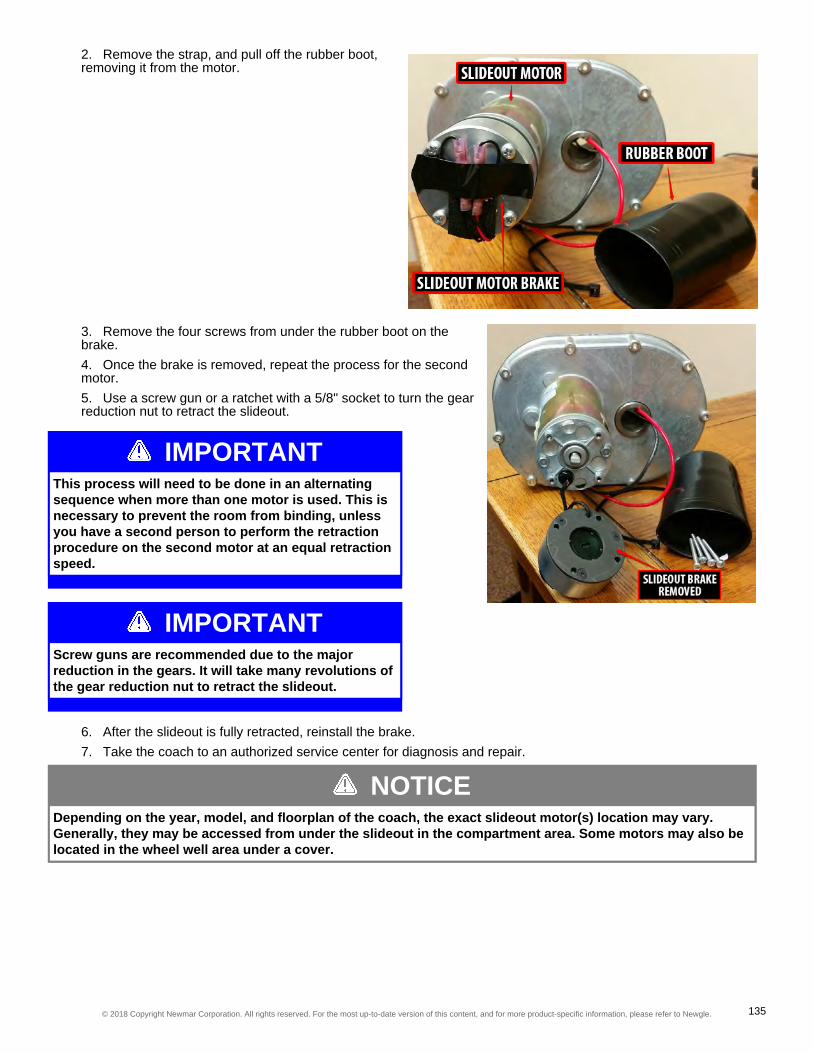
IMPORTANTThis process will need to be done in an alternatingsequence when more than one motor is used. This isnecessary to prevent the room from binding, unlessyou have a second person to perform the retractionprocedure on the second motor at an equal retractionspeed.
IMPORTANTScrew guns are recommended due to the majorreduction in the gears. It will take many revolutions ofthe gear reduction nut to retract the slideout.
2. Remove the strap, and pull off the rubber boot,removing it from the motor.
3. Remove the four screws from under the rubber boot on thebrake.4. Once the brake is removed, repeat the process for the secondmotor.5. Use a screw gun or a ratchet with a 5/8" socket to turn the gearreduction nut to retract the slideout.
6. After the slideout is fully retracted, reinstall the brake.7. Take the coach to an authorized service center for diagnosis and repair.
NOTICEDepending on the year, model, and floorplan of the coach, the exact slideout motor(s) location may vary.Generally, they may be accessed from under the slideout in the compartment area. Some motors may also belocated in the wheel well area under a cover.
© 2018 Copyright Newmar Corporation. All rights reserved. For the most up-to-date version of this content, and for more product-specific information, please refer to Newgle. 135

ELECTRIC KITCHEN SLIDEOUTSThe operating switch for the kitchen slideout is usually located in the overhead cabinet above thedriver or passenger chair or the overhead cabinet above the entrance door.
ELECTRIC KITCHEN SLIDEOUT OPERATIONIn order to operate the kitchen slideout with the required voltage levels, batteries should be fully charged, the generatorshould be powered on, or the coach should be connected to shore power. This maintains the voltage levels required tooperate the slideouts.Due to the slideout safety feature commonly referred to as ‘ignition lockout’, the operation of your slideout will beprohibited under one or more of the following conditions:
• Partial slideout operation is prohibited when the key is in the accessory or run position, allowing the slideout toretract, but not extend.• Total slideout operation is prohibited when the module receives an ignition signal when the key is in the runposition. However, the slideout will operate in the accessory position, because it does not receive an ignition signal.• Total slideout operation is prohibited when the ignition switch is in either the accessory or run position.• Total slideout operation is prohibited when the park brake is not set.• The disabling of the slideout is based on the individual slideout control module programming and the ignitionswitch circuit signal.
Once the appropriate safety feature conditions are met and the path of the slideout is unobstructed both inside andoutside of the coach, follow the operating instructions posted in your coach.
IMPORTANTRead entire slideout room instructions posted in your coach before extending or retracting the slideout.
ELECTRIC KITCHEN SLIDEOUT MAINTENANCEElectric slideout drive mechanisms do not require lubrication as part of the scheduled maintenance. Some noise isnormal during extension and retraction from the various moving parts and seals.
© 2018 Copyright Newmar Corporation. All rights reserved. For the most up-to-date version of this content, and for more product-specific information, please refer to Newgle. 136

IMPORTANTNewmar does not recommend the use of grease, silicone, or WD-40 on the slideout tubes or chains, as theseproducts tend to collect dirt and dust.
If lubrication is desired, Newmar recommends using a light coat of LPS 1 Greaseless Lubricant, which provides a drythin lubrication film that is resistant to dirt and dust buildup.
HOW TO MANUALLY RETRACT AN ELECTRICKITCHEN SLIDEOUT
IMPORTANTPrior to proceeding with a manual retraction procedure, make sure the ignition key is in the off position andthe park brake is set. Then, try retracting the slideout again, as some controllers require the ignition to be off,and others require the park brake to be set.
WARNINGThe manual retraction procedures are for emergency use only. These procedures bypass all normal safetyfeatures. It is the responsibility of the person(s) performing the procedure to watch for moving parts andpinch points in order to avoid injury.
If the kitchen slideout will not retract on its own, there are a few possible methods for retracting it manually.
MANUAL RETRACTION - METHOD 1Method one is quick, but requires the motor and gear box to be operational. This procedure bypasses the slidecontroller, switch, and the wiring.
NOTICEThis method can be performed on any single motor electric slideout.
Disconnect red and black wires that are connected to motor. Using the the wires attached to the motor, connect to 12vcordless battery to run slide out in. If wire polarity is reversed slide will run out instead of in. Disconnect the wire(s) fromthe cordless battery pack.
IMPORTANTIf the slideout motor has a brake installed, you must also hook one brake wire to the battery with the redslideout motor wire and one with the black slideout motor wire.
© 2018 Copyright Newmar Corporation. All rights reserved. For the most up-to-date version of this content, and for more product-specific information, please refer to Newgle. 137

MANUAL RETRACTION -METHOD 2Method two is the fastest method without using batterypower, and the most practical if the motor or gears fail. Thismethod requires a significant amount of manpower to pushin the slideout.
COACHES WITH A TRANTORQUE BUSHINGAND ROUND SHAFT
1. Loosen the trantorque bushing(s) at the slideoutmotor(s), allowing the slideout to extend and retract freely.2. Now the room can be pushed in manually with the assistance of several people.3. After the slideout has been pushed in, tighten the trantorque bushing to 175 FT Lbs.
COACHES WITHOUT A TRANTORQUEBUSHING AND WITH SQUARE SHAFT
1. Remove the four motor mounting bolts.2. Slide the motor(s) off of the square shaft. Due toclearance issues on some floorplans, it may benecessary to remove the brake to gain enoughclearance to slide the motor off of the shaft.3. Now the room can be pushed in manually with theassistance of several people.4. Reinstall the motor, motor mounting bolts and thebrake if it was removed.5. Take the coach to an authorized service center for diagnosis and repair.
MANUAL RETRACTION - METHOD 3Method three takes longer; however, only a few tools will beneeded. This procedure requires the gear box to beoperational. Follow the steps to manually retract theSlideout using wrench(s).
1. First, locate the strap that secures the rubber booton the outside of the motor.2. Remove the strap, and pull off the rubber boot toremove it from the motor.
© 2018 Copyright Newmar Corporation. All rights reserved. For the most up-to-date version of this content, and for more product-specific information, please refer to Newgle. 138

IMPORTANTWhen using a wrench to retract the slideout, makesure you do not damage the portion of the shaft thatwill slide through the motor, trantorque, bearing, andcog wheels.
3. Remove the four screws from under the rubber boot on thebrake.4. Once the brake is removed, use a wrench to turn the shaft toretract the slideout.
5. After the slideout is fully retracted, reinstall the brake.6. Take the coach to an authorized service center for diagnosis and repair.
NOTICEDepending on the year, model, and floorplan of the coach, the exact slideout motor(s) location may vary.Generally, they may be accessed from under the slideout in the compartment area.
ELECTRIC WARDROBE SLIDEOUTSThe operating switch for the wardrobe slideout is usually located in the bedroom, on the wall besidethe corresponding slideout.
ELECTRIC WARDROBE SLIDEOUT OPERATIONIn order to operate the bedroom slideout with the required voltage levels, batteries should be fully charged, thegenerator should be powered on, or the coach should be connected to shore power. This maintains the voltage levelsrequired to operate the slideouts.Due to the slideout safety feature commonly referred to as ‘ignition lockout’, the operation of your slideout will beprohibited under one or more of the following conditions:
• Partial slideout operation is prohibited when the key is in the accessory or run position, allowing the slideout toretract, but not extend.• Total slideout operation is prohibited when the module receives an ignition signal when the key is in the runposition. However, the slideout will operate in the accessory position, because it does not receive an ignition signal.• Total slideout operation is prohibited when the ignition switch is in either the accessory or run position.• Total slideout operation is prohibited when the park brake is not set.• The disabling of the slideout is based on the individual slideout control module programming and the ignitionswitch circuit signal.
Once the appropriate safety feature conditions are met and the path of the slideout is unobstructed both inside andoutside of the coach, follow the operating instructions posted in your coach.
© 2018 Copyright Newmar Corporation. All rights reserved. For the most up-to-date version of this content, and for more product-specific information, please refer to Newgle. 139

IMPORTANTRead entire slideout room instructions posted in your coach before extending or retracting the slideout.
ELECTRIC WARDROBE SLIDEOUT MAINTENANCEElectric slideout drive mechanisms do not require lubrication as part of the scheduled maintenance. Some noise isnormal during extension and retraction from the various moving parts and seals.
IMPORTANTNewmar does not recommend the use of grease, silicone, or WD-40 on the slideout tubes or chains, as theseproducts tend to collect dirt and dust.
If lubrication is desired, Newmar recommends using a light coat of LPS 1 Greaseless Lubricant, which provides a drythin lubrication film that is resistant to dirt and dust buildup.
HOW TO MANUALLY RETRACT AN ELECTRICWARDROBE SLIDEOUT
IMPORTANTPrior to proceeding with a manual retraction procedure, make sure the ignition key is in the off position andthe park brake is set. Then, try retracting the slideout again, as some controllers require the ignition to be off,and others require the park brake to be set.
WARNINGThe manual retraction procedures are for emergency use only. These procedures bypass all normal safetyfeatures. It is the responsibility of the person(s) performing the procedure to watch for moving parts andpinch points in order to avoid injury.
© 2018 Copyright Newmar Corporation. All rights reserved. For the most up-to-date version of this content, and for more product-specific information, please refer to Newgle. 140

MANUAL RETRACTION METHOD 1This method is quick, but requires the motor and gear box to be operational. This procedure bypasses the slidecontroller, switch, and the wiring. If battery power is unavailable or the motor/gear box is inoperable, move to the secondmethod.
IMPORTANTThis procedure is possible to perform on any single motor electric slideout.
1. Disconnect the red and black wires attached to the motor from the coach wiring.2. Using the the wires attached to the motor, connect to a 12 volt cordless battery to retract the slideout. If thewire polarity is reversed, the slideout will extend instead of retract.
IMPORTANTIf the slideout motor has a brake installed, you must also hook one brake wire to the battery with the redslideout motor wire and one with the black slideout motor wire.
1. Disconnect the wire(s) from the cordless battery pack.2. Take the coach to an authorized service center for diagnosis and repair.
MANUAL RETRACTION METHOD 2Determine which slideout setup your coach utilizes, and follow thesteps below pertaining to your specific setup.This method is the fastest one if the motor or gears fail, as it does notrequire battery power. However, this method requires a significantamount of manpower to push in the slideout.
1. Locate the slideout motor.2. Remove the covers from the motor if it is located in the wheelwell area.3. Loosen the trantorque bushing.4. Push the room into the retracted position.5. Retighten the trantorque bushing (175 ft. lbs. for 1" shafts or145 ft. lbs. for 3/4" shafts).6. Reinstall any removed covers.
-or-1. Locate the slideout motor.2. Remove the covers from the motor if it is located inthe wheel well area.3. Loosen the trantorque bushing.4. Turn the shaft with a wrench until the slideoutreaches the retracted position. Make sure you do notdamage the shaft with the wrench.5. Retighten the trantorque bushing (175 ft. lbs. for 1"shafts or 145 ft. lbs. for 3/4" shafts).6. Reinstall any removed covers.7. Take the coach to an authorized service center fordiagnosis and repair.
© 2018 Copyright Newmar Corporation. All rights reserved. For the most up-to-date version of this content, and for more product-specific information, please refer to Newgle. 141

WARDROBE SLIDEOUT MOTORWITH SQUARE SHAFTIF THE SLIDEOUT IS STUCK IN THEEXTENDED POSITION
1. Remove the four mounting bolts, and move over theslideout motor until it disengages from the square shaft.2. Manually push the room in or out, or use a wrench torotate the shaft. Make sure you do not damage the shaftwith the wrench.
WITH MANUAL LOCK ARMS3. Lock the room with manual lock arms (if equipped).4. Take the coach to an authorized service center fordiagnosis and repair.
WITH MECHANICAL LOCK ARMS3. Slide the motor back over onto the square shaft, and reinstall the four mounting bolts.4. Wedge a 2x4" board between the slideout fascia and the exterior wall at the front and back of the slideout roofto hold the slideout in the retracted position.5. Take the coach to an authorized service center for diagnosis and repair.
NOTICEDepending on the year, model, and floorplan of the coach, the exact slideout motor(s) location may vary.Generally, they may be accessed from under the slideout in the compartment area. Some motors may also belocated in the wheel well area under a cover.
© 2018 Copyright Newmar Corporation. All rights reserved. For the most up-to-date version of this content, and for more product-specific information, please refer to Newgle. 142
CARE AND MAINTENANCERecreational vehicles are complex machines and require maintenance to maintain both theappearance and functionality of the coach. General maintenance, inspection of components andseals, fluid changes, and many other maintenance items will help retain your coach's dependability,safety, visual appearance, and resale value.
IMPORTANTRead and follow all maintenance schedules to meet warranty requirements. Preventive maintenance andscheduled maintenance items are not warrantable. Damage caused by improper or unapplied maintenance isnot covered by your Newmar Limited Warranty.
HOW TO WASH AND DRY A COACHIMPORTANT
Damage caused by improper or unapplied maintenance is not covered by your Newmar Limited Warranty.
WASHING THE RVThe clear coat used on all painted portions of the exterior is a similar to the technology that used by car manufacturers.The same care needs to be performed and maintained on your coach exterior surface as on your automobile. Followingthese procedures can provide a long-lasting, high-gloss finish on your coach.
1. Make sure the coach's surface temperature is under 90˚ F. Never wash the vehicle in direct sunlight, while thevehicle is hot, or with hot water.2. Rinse the entire coach to remove all loose dirt and grime. Never hold a pressure washer close to the surface.Use a fan-type spray nozzle, making sure that the water is not a single straight stream. Keep the stream at least18 inches from the edge of any decals, as high pressure water may cause the decals to loosen and peel.3. Most car stores offer mild car wash shampoos that are safe for clear coat finishes. You may also use babyshampoo to prevent leaving a film on the coach. Adding ½ of a cup of food grade vinegar to three gallons of waterwill boost the cleaning ability and will also soften the water to help minimize water spots. Rinse thoroughly toprevent soap residue accumulation.
IMPORTANTDo not use dish soap, detergents with degreasing agents, or industrial cleaners, as they can cause damage tothe finish on your coach.
IMPORTANTDo not use solvents such as acetone, MEK, toluene, etc. on the decals. Any solvent including alcohol maysoften or smear colors. Do not use lacquer thinner or paint on decals. Do not overcoat the decals with clearpaint. Do not allow gasoline or other fuels to drip or stay on the decals for any length of time. If this occurs,immediately flush the area with water.
4. Use 100% cotton or Lambswool pads or wash mitts for washing the painted surfaces of your coach. Use adifferent mitt for washing the wheels and undercarriage.
The following products may assist you when cleaning your coach, and may be purchased through the Newmar partsdepartment:
• Lambswool Pad (Newmar part #018461)© 2018 Copyright Newmar Corporation. All rights reserved. For the most up-to-date version of this content, and for more product-specific information, please refer to Newgle. 143

• Backer Pad (Newmar part #018461A)• Lambswool Mitt (Newmar part #018464)• Extension Pole (Newmar part #018463)5. Change the water in your wash bucket often, or place a “dirt guard” in bottom of the bucket to keep thecleaning pad or wash mitt free of dirt and debris.
IMPORTANTAbsolutely no brushes should be used on the painted surface of your coach, as it will cause damage to thefinish, just as it would an automobile finish. Newmar does not support the use of any style, type, or brushmaterial, even though it may be marketed as 'RV Safe' or 'Approved.'
CAUTIONThe use of any cleaning products outside of Newmar's recommendation is at the customer's discretion.However, Newmar and BASF take no responsibility for any scratches, swirls, or damage to the finish of thecoach caused by the use of non-recommended products.
DRYING THE RVDrying your RV is just as important as washing it. Tap water and well water contain many chemicals that could waterstain your coach's finish. After washing, dry your coach with the EZE Squeegee (Newmar part #018462) or a clean100% leather chamois.
IMPORTANTYou can also use fresh microfiber towels for drying. Please use caution, as these towels are made partiallywith polyester (plastic), which can break down over time from extended use and washing, eventually causingdamage to the clear coat finish.
MAINTAINING YOUR DIAMOND SHIELD PAINT PROTECTIONFor information on how to maintain your Diamond Shield Paint Protector, refer to the "Paint, Roof, and Siding" sub-category under the Exterior Category.
WAXING AND POLISHING A COACHThe coating on your coach is a state-of-the-art base coat and Urethane clear coat. The clear coating is designed toprotect the colored base coat, so it needs to be maintained, especially in harsh environments. Clear coats will appear tofade or lose gloss as the surface becomes contaminated by the environment. A finish that is dull or low in gloss is aresult of contamination. Occasional washing alone will not adequately remove some forms of contamination and willrequire polishing of the finish.The exterior finish of your coach will require a routine waxing. When water will not bead and roll off a freshly washedvehicle, a new coat of wax is needed. Wax not only improves the appearance of the vehicle, but it also protects thefinish against oxidation and corrosive materials. The recommended type of wax is one that is compatible with painted orgel-coated fiberglass finishes, and contains a UV (ultra-violet) inhibitor. Buffing with a polishing compound will improve adull or discolored finish.
IMPORTANTWhen using a polishing compound that does not contain a wax preservative, reapplying a coat of hard waxafter polishing is recommended.
© 2018 Copyright Newmar Corporation. All rights reserved. For the most up-to-date version of this content, and for more product-specific information, please refer to Newgle. 144

Gas Coach Water Compartment (Example Only)Diesel Coach Water Compartment (Example Only)
IMPORTANTDo not use products that contain harsh abrasives such as rubbing compounds, as these products shouldonly be used by an experienced technician with proper training and equipment.
BENEFITS OF WAXING AND POLISHING• Remove minor surface imperfections caused by water spots and acid rain• Remove minor scratches by filling them and leveling the surface• Seal the pores of the finish, creating an easier-to-clean surface• Beautify the paint finish appearance with more depth and high gloss• Protect the paint finish from the elements
Most polishes and waxes are designed to clean and polish in one application, whether by hand or machine. A machine-applied polish will last longer than one applied by hand, as the high RPMs of the buffing wheel create heat, resulting in adeeper film with higher gloss. However, a hand-applied polish or wax will offer outstanding performance and protect thecoach's finish.Due to the variations of polishes and waxes, incorporate the following:
• Apply polish or wax while the coach is parked in a shaded area so the coach's surface is at the specifiedtemperature according to the polish manufacturer's recommendations.• Condition the polishing pad by rubbing a slight amount of polish on it.• Use only the amount of polish specified in the label directions.• Work a small area at a time.• Rinse off and remove dried polish from crevices, trim,and moldings.
IMPORTANTRefrain from waxing or polishing for at least 90 days from the coach's date of manufacture.
HOW TO WINTERIZE A COACHNOTICE
The following instructions are generic to Newmar coaches, and are NOT specific to your coach. They shouldonly be used as a reference guide for this process. Appliances, drain locations, and plumbing componentsmay vary by coach. The following images are for example purposes only. Your coach may or may not beequipped with the same components as shown.
© 2018 Copyright Newmar Corporation. All rights reserved. For the most up-to-date version of this content, and for more product-specific information, please refer to Newgle. 145
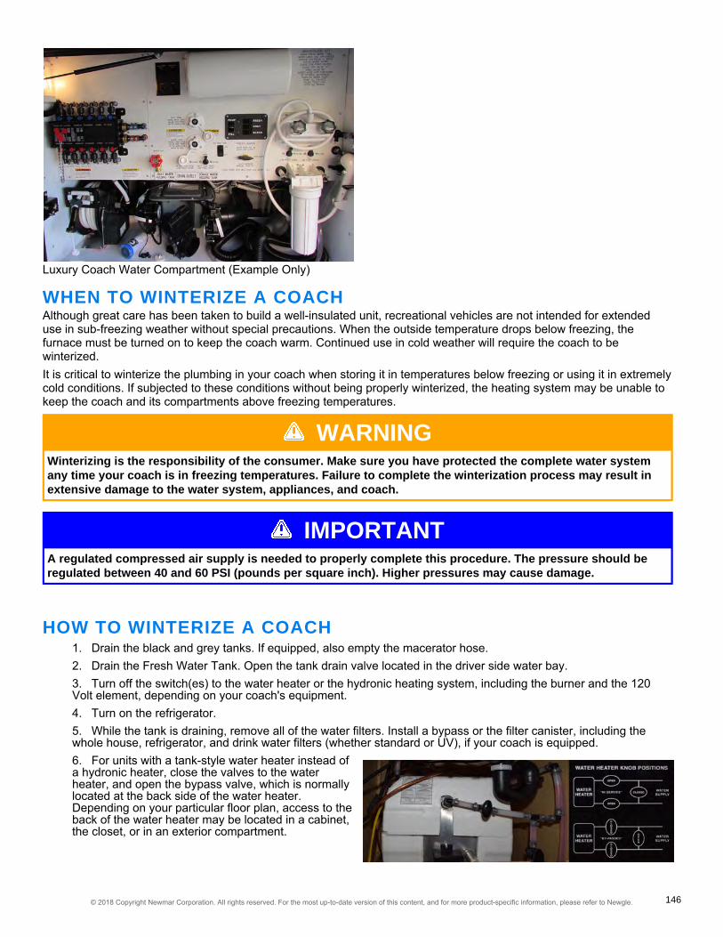
Luxury Coach Water Compartment (Example Only)
WHEN TO WINTERIZE A COACHAlthough great care has been taken to build a well-insulated unit, recreational vehicles are not intended for extendeduse in sub-freezing weather without special precautions. When the outside temperature drops below freezing, thefurnace must be turned on to keep the coach warm. Continued use in cold weather will require the coach to bewinterized.It is critical to winterize the plumbing in your coach when storing it in temperatures below freezing or using it in extremelycold conditions. If subjected to these conditions without being properly winterized, the heating system may be unable tokeep the coach and its compartments above freezing temperatures.
WARNINGWinterizing is the responsibility of the consumer. Make sure you have protected the complete water systemany time your coach is in freezing temperatures. Failure to complete the winterization process may result inextensive damage to the water system, appliances, and coach.
IMPORTANTA regulated compressed air supply is needed to properly complete this procedure. The pressure should beregulated between 40 and 60 PSI (pounds per square inch). Higher pressures may cause damage.
HOW TO WINTERIZE A COACH1. Drain the black and grey tanks. If equipped, also empty the macerator hose.2. Drain the Fresh Water Tank. Open the tank drain valve located in the driver side water bay.3. Turn off the switch(es) to the water heater or the hydronic heating system, including the burner and the 120Volt element, depending on your coach's equipment.4. Turn on the refrigerator.5. While the tank is draining, remove all of the water filters. Install a bypass or the filter canister, including thewhole house, refrigerator, and drink water filters (whether standard or UV), if your coach is equipped.6. For units with a tank-style water heater instead ofa hydronic heater, close the valves to the waterheater, and open the bypass valve, which is normallylocated at the back side of the water heater.Depending on your particular floor plan, access to theback of the water heater may be located in a cabinet,the closet, or in an exterior compartment.
© 2018 Copyright Newmar Corporation. All rights reserved. For the most up-to-date version of this content, and for more product-specific information, please refer to Newgle. 146
NOTICEFor units with a tankless water heater, do NOT put the water heater in by-pass mode. Instead, blow it out, andinstall the antifreeze as directed for a hydronic heater.
7. Remove the drain plug at the bottom of the water heater tank on the exterior of the coach.
IMPORTANTThe 120 Volt water heater element must be turned off by flipping the switch near the water heater's drain plug.
8. Open the low point drains by turning the valve to the "open" position or by pulling up on the handle if the coachis equipped with T-Handle valves. There should be one drain for hot and one for cold, and they are normallylocated in the water compartment.9. Connect the regulated air supply to the inlet of the hose from the hose reel (if equipped) or the city water fillinlet. Air will flow out of the low point drains.10. Cycle all faucets and the auto fill or tank fill valve (whichever the coach is equipped with) to all possiblepositions for a minimum of 10 seconds at each position. Do not forget the hot water spigot with low point drain nextto the generator (if equipped).11. Cycle the tank fill valve to all positions in order to purge water out of the lines and valve assembly.
IMPORTANTOn coaches equipped with Aqua View Showermi$er Fresh Water Reclamation System, cycle the valve to thebypass position to purge the water out of the line back to the fresh water tank while pressurized air supply isconnected. Then place the valve back to normal flow mode to the shower head, and then purge the shower.Do not leave the valve in bypass mode when running antifreeze in the line because it will allow antifreeze intothe fresh tank.
12. After blowing the water out of the system with pressurized air, disconnect the hose, and pour approximatelyone cup of antifreeze into the hose. Hook the hose back up to the pressurized air, and blow the antifreeze throughthe hose and hose reel to protect it.13. Close the low point drains. This must be done prior to pumping antifreeze through the lines, or the antifreezewill be pumped onto the ground.14. Remove the whole house filter canister, and dump any remaining water, and reinstall.15. Locate the winterizing valves marked "A" & "B" located in the water compartment.16. Close valve "A" by rotating the valve clockwise. Open valve "B" by rotating the valve counter clockwise.17. Remove the plug at the end of the clear winterizing hose.18. Insert the hose into a jug or bucket of antifreeze.19. Replace the empty jugs, or refill the bucket as needed to complete the entire process.20. Turn on the water pump by activating water pump switch. Red antifreeze will start flowing through the clearhose into the water lines.21. Run cold water from the kitchen faucet until the red potable antifreeze is detected. Run hot water from thekitchen faucet until the antifreeze is detected.
IMPORTANTMake sure you run enough antifreeze through each faucet to fill each P-trap.
22. Proceed to the next faucet, and repeat process for each faucet, including the lavatory, shower sprayers, andoutside shower faucet. If equipped, repeat the process for the instant hot water, drinking water dispensers, and hotwater spigot with low point drain (next to the generator).
© 2018 Copyright Newmar Corporation. All rights reserved. For the most up-to-date version of this content, and for more product-specific information, please refer to Newgle. 147

IMPORTANTFor coaches equipped with a sink or shower connected to a Saniflo Sanivite lift pump, the lift pump must becompletely emptied, or enough RV antifreeze must be poured down the drains to allow the lift pump to cycleuntil the antifreeze concentration is sufficient for freeze protection. Pour at least one liter of antifreeze downthe drain connected to the lift pump. Make sure the pump cycles at least once, then pour another liter downthe drain. Wait for the lift pump to cycle again; then the remaining liquid in the lift pump should have anadequate antifreeze concentration at this point.
23. Flush each toilet until the red antifreeze is detected. If the toilet is equipped with a sprayer, activate and flushit until the antifreeze flows from the sprayer.24. Run the dishwasher through a cycle to winterize the water inlet plumbing, as well as the pump and drain line.25. If the coach is equipped, turn on the washing machine. Select a wash cycle setting that uses warm water toactivate both the hot and cold inlet valves. Allow the washing machine to fill for approximately two minutes. Pressthe "cancel" and "drain" selection to begin draining the machine. This will winterize the pump and drain, as well asthe washing machine's P-trap.26. Depress the refrigerator's external water dispenser while holding a container to catch the fluid. Continue to letthe fluid flow until the red antifreeze is detected.
NOTICEThe red antifreeze may not appear instantly, as most refrigerators have a reserve for cold water. However, ifyou did not remove the water filter in the refrigerator in Step 5, the fluid will run clear for a long time.
27. Make sure the ice maker is turned on. Once it reaches the proper temperature, it will attempt to make icecubes, which will become pink in color. This may take several hours. Once they become pink, turn off the icemaker and the refrigerator. Empty the ice cube tray, and clean out the ice maker and freezer area.28. Turn off the water pump. Close the winterizing valve "B", and open valve "A".29. Insert the plug into the clear hose, and stow the winterizing hose.30. If the coach is equipped, winterize the macerator by turning it on and emptying the black and gray holdingtanks, allowing the macerator and macerator hose to fill with antifreeze. If there is no macerator in the coach, usethe sewer hose to drain the black tank, followed by the gray tank.
HOW TO DE-WINTERIZE A COACHProvides the Newmar-recommended step-by-step instructions for de-winterizing a coach. This article contains writteninstructions, as well as a video demonstration, for this procedure.
1. Connect your water hose to a fresh potable water supply.2. Set the auto fill or tank fill valve for city water supply.3. Run water through each faucet, toilet, and shower on both hot and cold settings.4. Run the dishwasher and the washing machine through a complete cycle before using.5. Depress the refrigerator water dispenser while holding a container to catch the fluid being dispensed. Continueuntil clear water is dispensed.6. Install the refrigerator filter (if equipped).7. Turn off the water supply drain pressure from the system using low point drains. Install all filters in the system.
NOTICENewmar recommends installing clean filters unless the sanitization process will also be completed at thistime.
8. Close the low point drains.9. Turn on the ice maker, allowing it to run through multiple cycles. Throw away any ice with antifreeze. Clean outthe ice maker and the tray until clear ice is available.10. If the coach is equipped with a water heater, install a drain plug. Open the water heater valves, and close theby-pass valve on the back side of the water heater.11. Turn on the fresh potable water supply.
© 2018 Copyright Newmar Corporation. All rights reserved. For the most up-to-date version of this content, and for more product-specific information, please refer to Newgle. 148

12. Open the hot water faucet until the water heater is filled and flows through the faucet without air.13. Flip the water heater switch to the "ON" position. This is located near the drain plug (if equipped with a waterheater).14. Check the tank level, and dump if necessary.15. The coach is now ready to use.
HOW TO SANITIZE THE WATER SYSTEMNOTICE
The following instructions are generic to Newmar coaches, and are NOT specific to your coach. They shouldonly be used as a reference guide for this process. Appliances, drain locations, and plumbing componentsmay vary by coach.
WHEN TO SANITIZE THE WATER SYSTEMNewmar recommends sanitizing your water system under the following scenarios:
• Purchasing a new or used coach• After your coach has been in storage for a lengthy amount of time• If an unpleasant odor arises from your water• At least once per year for proper maintenance
HOW TO SANITIZE THE SYSTEM1. Drain the fresh water tank by turning the tank drain valve to the open position.2. Drain the water heater (if equipped) by removing the drain plug.
WARNINGDo not attempt to drain the water heater when the water is hot or the system is pressurized, as scalding mayoccur.
While the tank is draining, remove all of the water filters, including the refrigerator and drinking water filters (standard orUV), if your coach is equipped, and install a bypass.
NOTICENot all filters have a 'bypass,' so it may be necessary to install the canister without the filter.
3. Remove the main (whole house) filter housing.4. Remove the filter, and pour household bleach (1/4 cup per 15 gallons, as determined by your tank capacity)into the filter housing. For example: 1.75 cups of bleach for coaches equipped with a 105 gallon fresh water tank or1.25 cups of bleach for coaches equipped with a 75 gallon fresh water tank. This will approximately be a 50 ppm(parts per million) bleach solution.
IMPORTANTFor any coaches not equipped with a whole house filter, skip these steps. Instead, use a funnel to pour bleachinto the hose prior to hooking the coach up to a potable water supply.
5. Reinstall the housing and the water heater drain plug after it has drained completely.6. Hook up the water hose from the hose reel (if equipped), or hook up a drinking water-safe portable hose to apotable water source.7. Turn the valve to 'tank fill' or 'manual tank fill.'
© 2018 Copyright Newmar Corporation. All rights reserved. For the most up-to-date version of this content, and for more product-specific information, please refer to Newgle. 149

8. Turn on the potable water source, and completely fill the water tank. (This will flush the bleach/water solutionfrom the filter housing [Step 4] into the water tanks.)9. Turn off the tank fill valve (on non-auto fill coaches).10. Turn on the water pump.11. Run water out of one faucet on both hot and cold settings until a strong bleach smell becomes evident.12. Repeat this for all faucets, as well as the refrigerator, dishwasher, washing machine, toilets, low point drains,etc.
IMPORTANTTop off the water tank so that the sides and top of the tank are sanitized as well.
13. Turn on the refrigerator and the ice maker. Depending on your refrigerator model, the ice maker may have aflip lever or an ON/OFF switch. Let the ice maker run until the bleach/water solution is detected. This may take afew cycles. One cycle consists of the ice maker filling the trays with water, freezing the water, and then dumpingthe ice into the ice bin. This cycling process will occur automatically if the refrigerator, the ice maker, and the waterpump are all turned on.14. Disconnect the water hose, and dump out some water.15. Pour one ounce (1 oz.) of bleach into the water hose, and reconnect it to the potable water supply.16. Turn on the water for a brief moment to flush the bleach through the water hose, allowing it to mix in the hosereel or the portable hose used for potable water.17. Turn off the water supply, and disconnect the water hose.18. Cap the end of the hose.19. Let the bleach water sit in the system for a minimum of four hours. However, for best results, allow thesolution to sit overnight or up to 12 hours.20. Drain the fresh tank using the drain valve.21. Fill the fresh tank with clean potable water.22. Run water out of each faucet on both hot and cold settings until the bleach smell is no longer evident.
NOTICEIf the bleach smell is still noticeable, repeat steps 21-22 to flush the system again.
IMPORTANTIf algae or slime is detected in the fresh water system, it may be necessary to repeat the entire process untilthe system is flushed clean.
Once the system is flushed, Newmar recommends replacing the water filters. Do not re-use the contaminated filters, asthis will greatly reduce the effectiveness of the sanitization process.
IMPORTANTSanitizing through the winterization process will not sanitize the fresh tank or all of the water lines.
ULTRAFABRICS CLEANING GUIDELINES FORFLEXSTEEL AND VILLA FURNITURE1One of the best ways to keep Ultrafabrics looking great is through proper maintenance and regular cleaning to prevent
excessive dirt from accumulating.To keep these fabrics looking their best, following these guidelines will help to extend the life of the fabric:
• Use mild soap and water for everyday cleaning• Tough stains can be cleaned with alcohol-based or 1:5 bleach/water solutions — spray application recommended• Do not saturate
© 2018 Copyright Newmar Corporation. All rights reserved. For the most up-to-date version of this content, and for more product-specific information, please refer to Newgle. 150
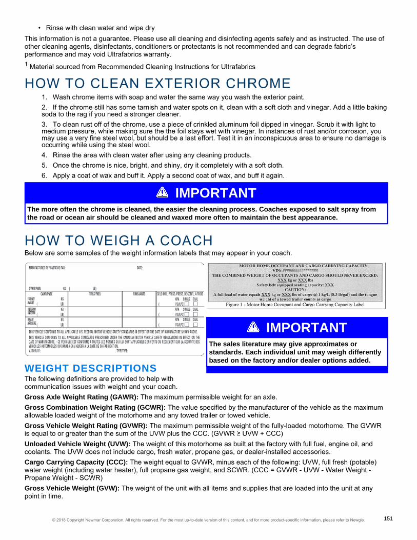
IMPORTANTThe sales literature may give approximates orstandards. Each individual unit may weigh differentlybased on the factory and/or dealer options added.
• Rinse with clean water and wipe dryThis information is not a guarantee. Please use all cleaning and disinfecting agents safely and as instructed. The use ofother cleaning agents, disinfectants, conditioners or protectants is not recommended and can degrade fabric’sperformance and may void Ultrafabrics warranty.1 Material sourced from Recommended Cleaning Instructions for Ultrafabrics
HOW TO CLEAN EXTERIOR CHROME1. Wash chrome items with soap and water the same way you wash the exterior paint.2. If the chrome still has some tarnish and water spots on it, clean with a soft cloth and vinegar. Add a little bakingsoda to the rag if you need a stronger cleaner.3. To clean rust off of the chrome, use a piece of crinkled aluminum foil dipped in vinegar. Scrub it with light tomedium pressure, while making sure the the foil stays wet with vinegar. In instances of rust and/or corrosion, youmay use a very fine steel wool, but should be a last effort. Test it in an inconspicuous area to ensure no damage isoccurring while using the steel wool.4. Rinse the area with clean water after using any cleaning products.5. Once the chrome is nice, bright, and shiny, dry it completely with a soft cloth.6. Apply a coat of wax and buff it. Apply a second coat of wax, and buff it again.
IMPORTANTThe more often the chrome is cleaned, the easier the cleaning process. Coaches exposed to salt spray fromthe road or ocean air should be cleaned and waxed more often to maintain the best appearance.
HOW TO WEIGH A COACHBelow are some samples of the weight information labels that may appear in your coach.
WEIGHT DESCRIPTIONSThe following definitions are provided to help withcommunication issues with weight and your coach.Gross Axle Weight Rating (GAWR): The maximum permissible weight for an axle.Gross Combination Weight Rating (GCWR): The value specified by the manufacturer of the vehicle as the maximumallowable loaded weight of the motorhome and any towed trailer or towed vehicle.Gross Vehicle Weight Rating (GVWR): The maximum permissible weight of the fully-loaded motorhome. The GVWRis equal to or greater than the sum of the UVW plus the CCC. (GVWR ≥ UVW + CCC)Unloaded Vehicle Weight (UVW): The weight of this motorhome as built at the factory with full fuel, engine oil, andcoolants. The UVW does not include cargo, fresh water, propane gas, or dealer-installed accessories.Cargo Carrying Capacity (CCC): The weight equal to GVWR, minus each of the following: UVW, full fresh (potable)water weight (including water heater), full propane gas weight, and SCWR. (CCC = GVWR - UVW - Water Weight -Propane Weight - SCWR)Gross Vehicle Weight (GVW): The weight of the unit with all items and supplies that are loaded into the unit at anypoint in time.
© 2018 Copyright Newmar Corporation. All rights reserved. For the most up-to-date version of this content, and for more product-specific information, please refer to Newgle. 151

Sleeping Capacity Weight Rating (SCWR): The manufacturer’s designated number of sleeping positions multiplied by154 pounds (70 kilograms).
IMPORTANTTo assure the accuracy of your weights, make sure the unit is always level during weighing.
WEIGHING YOUR COACHThe unit has been built to comply with the component suppliers' recommended limits to provide you with a realistic CCC.When loading the unit, distribute the items so that not all of the weight is added to one area of the unit.If you have questions as to what the weight of the unit isafter it has been loaded, take the unit to a drive-on scale oruse individual wheel scales, and verify that the weights arewithin the limits of those specified for the unit. Whenweighing the unit, follow these instructions. Failure to followthese instructions may give an erroneous weight reading.To find the total weight of the unit, pull the unit onto thescales so that all of the wheels are on the scale as shown.Record the weight. This is the GVW and should not exceedthe GVWR supplied by Newmar for the unit.
To find the total weight of the coach, except for the frontaxle, move the unit so that the front wheels are off thescales as shown. Record the weight. This weight should notexceed the total rating of the axles remaining on the scales.The front axle weight is determined by subtracting thisweight from the GVW that was obtained in step one. Thisamount should not exceed the listed front axle weight rating.
ALTERNATE WEIGHING PROCEDUREThe recommended procedure to accurately weigh amotorhome is on individual corner scales. Since these arenot always available, this diagram shows how to weigh amotorhome on a typical truck scale.Since only one corner can be weighed at a time, theremaining three corners need to be as close to the scale aspossible without being on the scale, and the unit needs tobe as level as possible. Remember, wind and rain cancause inaccuracies of weights.
IMPORTANTYour coach has been aligned at the factory as part of the production process. To provide optimum tirelongevity and offer the best handling characteristics, Newmar recommends you have your unit re-aligned afterloading your belongings. Though highly recommended, this alignment is not mandatory, and as such, is notwarrantable by Newmar or the chassis manufacturer.
FOR MORE INFORMATIONRefer to the "Tire Inflation Pressure Technical Information" article in Newgle to learn more about weighing your coach.
© 2018 Copyright Newmar Corporation. All rights reserved. For the most up-to-date version of this content, and for more product-specific information, please refer to Newgle. 152

ROUTINE MAINTENANCE SCHEDULEIMPORTANT
Always follow the chassis maintenance guidelines found in the chassis manufacturer owner’s manual.
All routine maintenance is the responsibility of the owner and is not covered by the Newmar Limited Warranty. Pleasenote that damage caused by improper or unapplied maintenance is not covered by the Newmar Limited Warranty.
IMPORTANTCosmetic adjustments and alignments must be performed within the first three (3) months from date oforiginal purchase for warranty consideration. Thereafter, these items are considered routine maintenance.
Items supplied by other manufacturers may require specific individual maintenance not listed herein. Please refer to themanufacturers’ suggested maintenance guidelines in the Owner’s Information Packet.
WEEKLY• Test smoke alarm, carbon monoxide detector, and propane gas detector.
MONTHLY• Check battery water level.
QUARTERLY• Clean range hood exhaust fan filter and blades.• Check gas lines for leaks with soap solution or leak detector.• Check operation of windows, latches, and hinges.• Clean the roof ducted air conditioner filter(s).• Clean and inspect all door and window seals, and reseal where necessary.• Inspect and reseal around the tub and shower area where necessary.• Lubricate the exterior door hinges and latches with a graphite (silicone) lubricant.• Check, clean, and tighten battery cables, and inspect batteries for proper fluid level.
BI-ANNUALLY• Inspect the slideouts for proper seals. If realignment is necessary, please contact an Authorized Newmar ServiceCenter.• Inspect the exterior rubber slideout seals, and apply a UV inhibitor, such as 303 Protectant.• Rotate the tires as recommended by the tire manufacturer.• Check all gas appliances for proper operation.• Have the propane system inspected by a qualified technician.• Lubricate the moveable parts on the entrance step.• Check and replace water filters.
ANNUALLY• Inspection of roof seams and joints should be performed by an Authorized Newmar Service Center. If resealing isnecessary, it is the owner’s responsibility and is not covered by the Newmar Limited Warranty.• Check mounting bolts on all electric slideout motors for proper torque. This should be performed by anAuthorized Newmar Service Center.• Sanitize the fresh water system.• Wax and buff all gel-coat surfaces on the vehicle.
© 2018 Copyright Newmar Corporation. All rights reserved. For the most up-to-date version of this content, and for more product-specific information, please refer to Newgle. 153

SERVICE RECORDUse this chart to keep track of all service work performed on the coach. For additional pages, refer to Newgle.
Date Service Center / Dealer Nameand Address Description of Service Work Performed Cost
xx/xx/xxxx Example Dealer Name and Address Example of Description of Service Work Performed xxxx.xx
© 2018 Copyright Newmar Corporation. All rights reserved. For the most up-to-date version of this content, and for more product-specific information, please refer to Newgle. 154

Date Service Center / Dealer Nameand Address Description of Service Work Performed Cost
© 2018 Copyright Newmar Corporation. All rights reserved. For the most up-to-date version of this content, and for more product-specific information, please refer to Newgle. 155

FUEL, OIL, AND MPG RECORDUse this chart to keep track of all odometer mileage, fuel, oil, and average MPG for the coach. For additional pages,refer to Newgle.
DateOdometerMileage
Fuel(Gallons)
Oil(Quarts)
AverageMPG
Cost DateOdometerMileage
Fuel(Gallons)
Oil(Quarts)
AverageMPG
Cost
© 2018 Copyright Newmar Corporation. All rights reserved. For the most up-to-date version of this content, and for more product-specific information, please refer to Newgle. 156

DateOdometerMileage
Fuel(Gallons)
Oil(Quarts)
AverageMPG
Cost DateOdometerMileage
Fuel(Gallons)
Oil(Quarts)
AverageMPG
Cost
© 2018 Copyright Newmar Corporation. All rights reserved. For the most up-to-date version of this content, and for more product-specific information, please refer to Newgle. 157

158© 2018 Copyright Newmar Corporation. All rights reserved. For the most up-to-date version of this content, and for more product-specific information, please refer to Newgle.


W H E N Y O U K N O W
THE DIFFERENCE
NEWMAR CORPORATION | 355 N DELAWARE ST | PO BOX 30NAPPANEE, IN 465500030 | 5747737791 | FAX 5747732895
www.newmarcorp.com