small cell deployments: recent advances and research ... · international workshop on femtocells...
TRANSCRIPT

1
Abstract—This paper summarizes the outcomes of the 5th
International Workshop on Femtocells held at King’s College
London, UK, on the 13th and 14th of February, 2012. The
workshop hosted cutting-edge presentations about the latest
advances and research challenges in small cell roll-outs and
heterogeneous cellular networks. This paper provides some
cutting edge information on the developments of Self-Organizing
Networks (SON) for small cell deployments, as well as related
standardization supports on issues such as carrier aggregation
(CA), Multiple-Input-Multiple-Output (MIMO) techniques, and
enhanced Inter-Cell Interference Coordination (eICIC), etc.
Furthermore, some recent efforts on issues such as energy-saving
as well as Machine Learning (ML) techniques on resource
allocation and multi-cell cooperation are described. Finally,
current developments on simulation tools and small cell
deployment scenarios are presented. These topics collectively
represent the current trends in small cell deployments.
Index Terms—Small cell, standardization, carrier
aggregation, MIMO, CoMP, eICIC, SON, green, backhaul,
cognition, game theory, learning, modeling, propagation,
simulation, stochastic geometry, deployment.
I. INTRODUCTION
UE to the proliferation of smart mobile devices and
innovative mobile data services, telecommunication
systems are facing increasing demands for ubiquitous
heterogeneous broadband mobile communications. It has been
predicted that the volume of wireless data will exceed that of
wired data by 2015. In order to realize the enormous data
capacity and meet user Quality of Service (QoS) requirements,
while keeping operators’ costs low, low-power low-cost small
cells operating in licensed spectrum, have been widely
considered as the most promising solution. Small cells include
femtocells, picocells, metrocells and microcells, in order to
increase the cell coverage and capacity. Due to their low cost
and easy deployment, small cells provide a viable and cost-
effective way to improve cellular coverage, capacity and
applications for homes, enterprises, as well as for metropolitan
and rural areas.
Driven by their attractive features and potential advantages,
the development and deployment of small cells have gained
tremendous momentum in the wireless industry and research
communities in recent years. Small cells have also attracted
the attention of standardization bodies, e.g., the 3rd
Generation Partnership Project (3GPP), Long Term Evolution
(LTE) and LTE-Advanced. However, it is worth noting that
the successful rollout and operation of small cells are still
facing significant technical challenges and issues.
The aim of this paper is to summarize the outcomes and
discussions of the 5th
International Workshop on Femtocells
held at King’s College London, UK, on the 13th
and 14th
of
February, 2012. The workshop hosted cutting-edge
presentations about the latest advances and research
challenges in small cell roll-outs and heterogeneous cellular
networks.
The rest of the paper is organized as follows. In Section II,
the standardization activities regarding small cells within
3GPP are reviewed. In Section III, the self-organization
features and related techniques of small cells are discussed.
Section IV presents 3GPP LTE-Advanced small cell Carrier
Aggregation (CA) techniques and performance evaluation. In
Section V, enhanced Inter-Cell Interference Coordination
(eICIC) is proposed for small cells and the related
performance is evaluated through simulations. In Section VI,
Multiple-Input-Multiple-Output (MIMO) techniques are
Small Cell Deployments: Recent Advances and
Research Challenges
Zubin Bharucha, DOCOMO Eurolabs, Germany,
Emilio Calvanese, CEA-LETI, France,
Jiming Chen, Ranplan Wireless Network Design Ltd, UK
Xiaoli Chu, University of Sheffield, UK,
Afef Feki, Bell-Labs, France,
Antonio De Domenico, CEA-LETI, France,
Ana Galindo-Serrano, CTTC, Spain,
Weisi Guo, University of Sheffield, UK,
Raymond Kwan, Ubiquisys, UK,
Jimin Liu, Ranplan Wireless Network Design Ltd, UK,
David López-Pérez, King’s College London, UK,
Massod Maqbool, SAGEMCOM, France,
Ying Peng, Datang Telecom Group, China,
Samir Perlaza, Princeton University, USA,
Guillaume de la Roche, Mindspeed Technologies, France,
Serkan Uygungelen, DOCOMO Eurolabs, Germany,
Alvaro Valcarce, Triagnosys, Germany,
and Jie Zhang, University of Sheffield, UK
D

2
explored for small cells to achieve spatial multiplexing. In
Section VII, the trade-off between spectral, energy and cost
efficiencies offered by the new architecture of small cell
networks is studied. Section VIII reviews Radio Resource
Management (RRM) techniques based on Reinforcement
Learning (RL) techniques for small cells. Section IX
introduces techniques enabling decentralized operation of
small cells. In Section X, a comprehensive LTE system-level
simulator is presented. In Section XI, static and mobile
deployment scenarios of small cells are discussed.
Conclusions are drawn in Section XII.
II. 3GPP STANDARDIZATION
The International Telecommunications Union (ITU)
officially issued the first release of the 4th Generation (4G)
mobile telecommunications systems - International Mobile
Telecommunications (IMT)-Advanced standard - in March
2011. Meeting the rapid increase in mobile data traffics is a
crucial challenge for any future mobile systems. Therefore,
ITU has raised harsh requirements on peak data rates and
spectrum efficiency for IMT-Advanced systems [2], e.g., peak
data rates above 600 Mbps, a Downlink (DL) peak spectrum
efficiency of 15 bps/Hz, and an Uplink (UL) peak spectrum
efficiency of 7.5 bps/Hz. In October 2009, the LTE-Advanced,
evolution of the 3rd Generation (3G) Wideband Code Division
Multiple Access (WCDMA) and Time-Division Synchronous
Code Division Multiple Access (TD-SCDMA) systems, was
submitted to the ITU as an IMT-Advanced candidate system
and thereafter as a 4G standard system [1].
In order to meet IMT-Advanced standard requirements with
limited radio resources, deploying Low Power Nodes (LPNs),
such as Remote Radio Heads (RRHs), picocells, femtocells
and relay nodes, overlaid on the existing macrocell network
has been heralded as the most promising solution. Therefore,
this type of networks, referred to as Heterogeneous Networks
(HetNets), has been and will continue to be widely
investigated in 3GPP. The HetNet concept has been included
into a number of study/work items in LTE-Advanced, in
conjunction with advanced technologies such as CA, non-CA
based eICIC and its improvements, i.e., Coordinated Multi-
Point transmission and reception (CoMP), and enhanced
PDCCH (ePDCCH). Moreover, in LTE-Advanced, Evolved-
Universal Terrestrial Radio Access Network (E-UTRAN)
protocols and network interfaces are also being enhanced.
In LTE Rel-10 (the first version of LTE-Advanced), CA
supports cross carrier scheduling, in which User Equipments
(UEs) can detect PDCCH, PCFICH and PHICH from a subset
of existing Component Carriers (CCs). This is an effective
interference management technique in HetNets, since it allows
scheduling control channels in one CC while scheduling data
channels in another CC. In this way, inter-cell interference to
control channels can be efficiently mitigated. CA and cross
carrier scheduling are also being investigated in LTE Rel-11
[3]. Whether or not inter Base Station (BS) signaling is
required for robust and autonomous inter-cell interference
management and how each BS selects those CCs that
maximize the overall network performance are being studied.
CA based solutions are attractive for scenarios with large
availability of spectrum and CA capable UEs. However, non-
CA based solutions are still needed to enable HetNet operation
in scenarios with limited spectrum and UEs without CA
capability [4], e.g., co-channel deployments. Simple cell
splitting and LTE Rel-8/9 ICIC in co-channel deployments
with unbalanced transmit powers among BSs cannot provide
sufficient cell-edge coverage and interference mitigation.
Moreover, mechanisms allowing off-loading from macrocells
to Low Power Nodes (LPNs), e.g., range expansion, may
worsen cell-edge capacity. Hence, new interference
management techniques are required for HetNet co-channel
deployments. For example, the eICIC in LTE Rel-10 is mainly
based on Time Domain (TD) resource partitioning through the
use of Almost Blank Subframes (ABS), and introduces
restricted RRM, Radio Link Monitoring (RLM) and Channel
State Information (CSI) measurements to deal with varying
inter-cell interference conditions in the time domain, while
maintaining satisfactory DL and UL coverage. ABS patterns
need to be carefully designed in order to protect control
channels such as SCH/PBCH/SIB1/Paging and ensure Hybrid
Automatic Repeat Request (HARQ) timing. ABS information
can be exchanged between cells through the X2 interface.
eICIC based on DL power control at femtocells and UL power
control at UEs were discussed in LTE Rel-10 for inter-
femtocell interference scenarios, but both power control
approaches were considered as implementation issues.
Due to time limitation, some other identified eICIC
techniques were de-prioritized in LTE Rel-10. Particularly, the
impact of legacy transmissions on control and data channel
demodulation when using ABS was left to be considered in
LTE Rel-11, leading to Further enhanced ICIC (FeICIC). The
ongoing work item on FeICIC attempts to identify
UE performance requirements, possible air interface
changes and enhanced Node B (eNB) signaling
improvements, in order to enable significantly improved
detection of Physical Cell Identity (PCI) and system
information (e.g., MIB/ SIB1/Paging) in the presence of
dominant interferers depending on UE receiver
implementations;
UE performance requirements and UE signaling required
for both significantly improved DL control and data
detection and UE measurement/reporting in the presence
of dominant interferers depending on UE receiver
implementations [5]; and
network assistance information for Common Reference
Signal (CRS) interference cancellation, improved
detection of system information, and usage of reduced
power ABS.
In LTE Rel-11, enhanced DL physical control channel(s)
are also being investigated to allow control channel inter-cell
interference mitigation.

3
CoMP was another technique proposed to enhance
coverage, data rates, cell-edge throughput and system
performance in LTE-Advanced. Its studies have been in
progress since LTE Rel-9, with a work item set up in LTE
Rel-11. CoMP scenarios 3 and 4 [6], for HetNets with low
power RRHs overlaid on the macrocell network, extend the
co-channel deployment ICIC research into data transmission
enhancement. Instead of the semi-static coordination in eICIC
via X2 interface, DL CoMP [6] implies dynamic coordination
among multiple geographically separated transmitting and/or
receiving points. DL CoMP techniques, such as simultaneous
data transmissions from multiple points to a single or multiple
UEs (i.e. Joint Transmission (JT)), Dynamic Transmission
Point Selection (DTPS), Coordinated Scheduling (CS) and
Coordinated Beamforming (CB), can turn interference into
useful signals, and improve the received signal quality and/or
data throughput. UL CoMP may facilitate multi-user
transmissions, power control and detection of control channels
in HetNets.
Besides inter-cell interference mitigation, 3GPP also works
on protocol enhancement, UE mobility and network interfaces
for HetNets. For example, in LTE Rel-9, the femtocell
synchronization problem was widely studied. In LTE Rel-10,
intra Closed Subscriber Group (CSG) femtocell mobility was
enhanced, where X2-based handover between femtocells is
allowed if no access control is required at the Mobility
Management Entity (MME). In other words, handover is
allowed between CSG or hybrid access femtocells with the
same CSG identity, or when the target femtocell is an open
access femtocell. Such handover assumes direct X2
connectivity between femtocells, no matter whether any of the
involved femtocells is connected to a femtocell Gateway
(GW) or not [7]. Seamless and robust mobility of UEs from
macrocells to LPNs and vice versa is also considered in Rel-
11 [9] to enable off-loading benefits.
Scenarios with multiple LPN-layers and carriers may
require additional reestablishment procedures to improve
overall system robustness. In this line, large-scale evaluation
is needed for strategies to evaluate LPN discovery/
identification and HetNet mobility performance under Rel-10
eICIC features. LTE Rel-11 is also evaluating the benefits of
enhanced inter-CSG mobility, X2 connection via a GW for
macrocell/femtocell to femtocell mobility enhancement, and
deployment scenarios with two GWs directly interconnected
to each other [8].
III. SELF-ORGANIZATION
Self-organization has been considered as a key feature of
LPNs. Since the number of LPNs to be deployed is expected
to be large and LPNs are likely to be plug and play devices
deployed by operators/users in an uncoordinated manner, it is
not feasible for operators to optimize LPN deployments using
traditional network planning and optimization techniques.
Therefore, LPNs should adapt their parameters independently
and autonomously on a regular basis depending on network,
traffic and channel fluctuations. Self-organization has attracted
much momentum in 3GPP standardization through a number
of work items.
Self-organizing Network (SON) operations usually consist
of three phases:
Self-configuration, which is performed at start-up and
configures initial parameters, e.g., a LPN initializes its
transmit power according to the received power from the
closest macrocell.
Self-optimization, which is performed on a regular basis
and tunes parameters according to network, traffic and
channel fluctuations, e.g., LPNs may tune their handover
thresholds depending on traffic load.
Self-healing, which automatically detects network
failures and corrects/mitigates them, e.g., if a cell is out
of order, the neighboring cells may take over its traffic
by enlarging their coverage.
Self-organization of a cell usually takes the parameters of
neighbouring cells into account. For instance, self-organized
inter-cell interference mitigation requires neighbouring cells to
reduce coverage overlap while supporting seamless handovers.
Self-organizing schemes can be generally categorized into the
following two kinds:
Centralized schemes, where a global entity is in charge
of a given number of cells and is responsible for their
optimization. In a centralized approach, LPNs can
forward their configurations and measurements to a
server, which will optimize relevant parameters based on
overall network information.
Distributed schemes, where each cell optimizes its own
parameters based on local sensing and optimization
techniques. Using distributed techniques, LPNs may
learn about neighbouring cells and fine tune relevant
parameters in a faster manner.
In practice, pure centralized schemes are difficult to
implement, especially for a large number of cells. In such
scenarios, the large number of parameters to be optimized and
the associated significant signalling overhead may lead to high
complexity. Distributed schemes face challenges arising from
network, traffic and channel uncertainties, and inaccuracies in
data obtained from neighbouring cells. Hybrid approaches,
where some of the parameters are optimized in a centralized
manner whereas others are optimized in a distributed manner,
can be used to achieve a good trade-off.
Sensing plays a key role in the proper operation of
distributed schemes, and can be performed in different ways:
Network monitor mode: LPNs are able to scan, listen and
estimate parameters from neighbouring cells.
Measurement reports: it is proposed in LTE that UEs
send measurement reports to their serving cells. When
many UEs are located in the LPN coverage, the large
amount of measurement reports collected can provide an

4
accurate knowledge of its radio environment.
Cooperative BSs: LPNs exchange information via a
dedicated air interface or backhaul.
Each time the central server (in centralized SON) or the cell
(in distributed SON) gathers fresh data, it can perform a new
optimization if necessary. In 3GPP LTE-Advanced, the
following use cases/parameters may be optimized:
Coverage and capacity optimization: A typical SON task
is to maximize network coverage and capacity. Cells size
are typically optimized so that the overlap between
neighbouring cells is minimized. Most existing solutions
are related to transmit power optimization, based on the
network monitoring mode, where a cell adapts its
transmit power depending on the power received from
the neighbouring cells so that its connected UEs can
always maintain a useful Signal to Noise Ratio (SNR)
level within a targeted radius.
Energy saving: Energy saving for green networking is
mainly realized by preventing cells from emitting at full
power when there is no UE to serve.
Interference reduction: Interference reduction can be
performed through transmit power control and/or
resource allocation. For instance, a LPN device scans the
whole spectrum and chooses empty bands to transmit.
Operators can also deploy their cells in orthogonal bands,
reducing inter-cell interference with a low complexity
but at the cost of reduced maximum performance.
Automated configuration of PCI: In LTE, it is suggested
that each cell should be able to automatically choose its
cell identity. It is a challenging task due to the limited
number of cell identities available, which may lead to
identity collision or confusion. Therefore, gathering data
from neighbouring cells to make a decision is important,
especially in scenarios with large cell densities.
Mobility robustness optimization: In LTE, small cells are
required to optimize their handover parameters, assisted
by previous handover-failure and ping-pong data.
Mobility load balancing optimization: Small cells must
be able to optimize cell re-selection and handover
parameters to balance traffic load and minimize the
associated number of handovers and redirections.
Automatic Neighbouring Relation (ANR) function: A
small cell must find ways to maintain an updated list of
neighbouring cells.
ICIC: Neighbouring cells collaborate through ICIC to
allocate their transmit power and Resource Blocks (RBs)
in a way that inter-cell interference is minimized.
Random Access Channel (RACH) optimization: RACH
settings need to be optimized to minimize interference
among RACHs, and thus reducing the RACH collision
probability, which affects call setup delays.
In 3GPP standards, parameters optimization is left up to the
manufacturer/operator. Recent researches on SON techniques
focus mainly on three approaches: cognition, game theory and
learning, which are introduced in Section IX. Distributed SON
techniques are more appealing to operators because they
reduce deployment and maintenance costs, and may lead to
near optimal solutions. Accordingly, a main challenge is to
develop simple SON techniques that can be implemented on
cheap devices with limited computing capabilities to provide
near optimum network performance.
IV. CARRIER AGGREGATION
LTE-Advanced, as an evolved version of LTE, set up more
challenging performance targets [10]. One target of LTE-
Advanced is to support transmission bandwidths of up to 100
MHz. This is achieved through CA, where multiple blocks of
legacy LTE spectrum, i.e. CCs, are amalgamated to obtain a
wider bandwidth [11] [12], while backward compatibility is
maintained so that LTE-capable-only UEs can operate in an
LTE-Advanced network and vice-versa. This is because each
CC for LTE-Advanced CA is a legacy LTE carrier.
With the additional degree of freedom that arises with CA
in the frequency domain, interference mitigation can be
achieved by optimizing the allocation of available CCs among
contending macrocell BSs and LPNs. CC selection methods,
depending on the interference environment of BSs in an LTE-
Advanced system, have been proposed in [13]-[16]. However,
the methods in [13]-[15] require excessive signalling overhead
among BSs. In [16], the proposed method reduces signalling
overhead, but fails to offer explicit protection to cell-edge UEs
in dense and uncoordinated deployments.
A. CA Analysis and Techniques
In this section, a novel Dynamic Autonomous Component
Carrier Assignment (DACCA) scheme is proposed, where
each BS in the network adapts its CC usage to protect cell-
edge UEs from detrimental DL inter-cell interference without
compromising spectral efficiency. In order to enable DACCA,
two types of CCs are defined according to their usage foreseen
by BSs: Primary CCs (PCCs) and Secondary CCs (SCCs).
PCCs are used to protect cell-edge UEs from inter-cell
interference so as to boost cell-edge capacity. The PCCs of a
particular BS cannot be used by its interfering cells, which are
identified using a pre-defined global Signal-to-Interference-
plus-Noise Ratio (SINR) threshold γth, which represents the
minimum tolerable SINR of UEs. In order to ban/block CCs at
interfering cells, the BS send a PCC indicator to it interfering
cells, which will then abstain from using the indicated CC.
Thus, cell-edge UEs allocated in PCCs will experience low
inter-cell interference.
SCCs are used to enhance spatial spectrum reuse. SCCs are
orthogonal to PCCs, and cannot be blocked at any cells. SCCs
can be allocated by cells to cell-centre UEs that face less
interference, as long as they do not cause high interference to
neighbouring cells.

5
The CC configuration in a cell remains unchanged within
each time slot, but may be updated at the start of the next time
slot. Each BS computes the CC assignment for the next time
slot based on the feedbacks received from its connected UEs
and neighbouring BSs regarding the previous time slot or even
earlier ones.
The proposed DACCA has a low signalling overhead, since
existing LTE signalling procedures are used, and the system
reaches a stable point after only a few iterations.
Fig. 1 shows an example of DACCA, where BS C may
cause interference to UE 1 served by BS A in CC1 (as a PCC)
and UE 3 served by BS B in CC2 (as a PCC). Both CC1 and
CC2 are thus blocked at BS C to avoid inter-cell interference.
Similarly, BS A cannot use CC2, while BS B cannot use CC1.
Since UE 2, served by BS A, is unlikely to be interfered by BS
B or BS C, it can be allocated in CC3 without causing
high interference to UE 4 served by BS C in CC3.
Fig. 1 DACCA with 3 CCs contained in the system bandwidth.
Fig. 2 DACCA operation with 3 CCs in the system bandwidth.
Fig. 2 illustrates the operation of DACCA at BS A, where
in step , BS A collects channel quality measurements from
its UEs; in step , BS A receives PCC indicators from its
neighbouring cells; in step , BS A updates its CC
assignment for the next time slot based on the received
feedbacks; in step , BS A allocates DL resources to its UEs
according to the CC assignment; and in step , BS A sends a
PCC indicator to its interfering cells. All BSs in the network
perform the same DACCA operation independently. More
detail on the allocation of CCs and RBs can be found in [17].
B. Performance Evaluation
The performance of DACCA is benchmarked using the DL
of an LTE-Advanced network with a total system bandwidth
of 40 MHz, which is divided into 4 CCs of 10 MHz bandwidth
each. Each CC is comprised of a fixed number of RBs, which
are the minimum DL resource allocation units in LTE-
Advanced. A BS can assign RBs of the same CC to multiple
UEs, but an RB can be assigned to at most one UE in a cell.
System-level simulations are performed using a one-story
building scenario, modelled by a 5×5 grid, according to 3GPP
specifications [34]. For the sake of simplicity, inter-cell
interference from macrocells to femtocells is neglected, which
may be accomplished by allocating orthogonal frequency
bands to macrocells and femtocells. The presence of a CSG
femtocell in an apartment block is governed by the probability
of CSG femtocell deployment, and CSG femtocells are
uniformly distributed inside apartments. UEs are uniformly
distributed inside apartment blocks containing a femtocell and
are forced to connect to it. A full buffer traffic model for UEs
is considered, and throughput calculations are derived from
the effective SINR of each scheduled UE by using a truncated
Shannon bound approach. More details on the simulation
scenario and parameter setting can be found in [17].
The performance of DACCA is compared to that of a Fixed
Frequency Reuse (FFR) scheme where one BS is assigned one
or two out of four available CCs, i.e. FFR 1/4 and FFR 2/4,
respectively. For DACCA, in the first time slot, BSs randomly
assign one CC as PCC and subsequently update their PCC and
SCC assignment according to the proposed scheme. The SINR
threshold γth is set to 5 dB.
Fig. 3 plots the Cumulative Distribution Functions (CDFs)
of the achieved DL SINR for the three considered schemes.
With DACCA, nearly all UEs achieve an SINR exceeding
γth=5 dB, thus providing fairness. However, the network
achieves the best average SINR performance when femtocells
use FFR 1/4, with which inter-cell interference is mitigated at
the cost of reduced spectrum efficiency.
Fig. 3 CDF of UE SINR.

6
Fig. 4 shows the CDFs of the achieved UE capacity for the
three schemes. Despite the encouraging SINR performance of
FFR 1/4, it presents the worst UE average capacity due to the
reduced spectrum efficiency. FFR 1/2 doubles the bandwidth
for each cell and thus doubles the UE average capacity with
respect to FFR 1/4, but worsens cell-edge performance. This is
a typical trade-off in FFR: the less bandwidth per cell, the
better SINR and cell-edge performance, but the worse UE
average capacity. On the contrary, DACCA outperforms both
FFR schemes, presenting a promising cell-centre performance
in terms of very high average UE capacity, while showing an
adequate cell-edge performance.
Fig. 4 CDF of UE Capacity.
V. ENHANCED INTER-CELL INTERFERENCE COORDINATION
New cell selection procedures that allow a UE to connect to
the BS with the lowest path loss regardless of its DL Received
Signal Strength (RSS) are being developed for a better spatial
reuse. An approach under investigation is range expansion [5],
in which a positive offset is added to the DL RSS of picocell
pilot signals to increase their DL coverage footprint. Although
range expansion mitigates UL cross-tier interference, it comes
at the expense of reduced DL signal quality for Expanded
Region (ER) picocell UEs (PUEs). The ER PUEs may suffer
from DL SINRs below 0 dB, since they may connect to cells
that do not provide the strongest DL RSS. Therefore, novel
eICIC schemes for macrocells to cooperate with ER picocells,
are required to mitigate excessive DL inter-cell interference
for range expansion [18]-[20].
Within 3GPP, eICIC approaches based on ABSs have been
proposed to mitigate cross-tier interference in range expansion
scenarios. ABSs are LTE subframes that contain reference
signals only, instead of control or data signals. As explained
above, without inter-cell coordination, ER PUEs may observe
high DL cross-tier interference from a macrocell, which can
be mitigated by using ABSs at the macrocell and scheduling
ER PUEs within the subframes that overlap with the ABSs of
the macrocell. However, using ABSs may degrade the overall
macrocell performance, since a given number of subframes are
kept unused in order to achieve interference mitigation.
A. Proposed eICIC Technique
In this subsection, a macro-pico coordinated RB and Power
Allocation (coRPA) scheme that deals with DL macro-to-pico
interference and enhances the macrocell performance, is
proposed. The idea is that when a UE enters or stays within
the ER of a picocell, the pico BS will inform the macro BS of
the set of RBs allocated to this ER PUE, and then the macro
BS will lower its transmit power in the specified RBs so that a
desired DL SINR is guaranteed to this ER PUE. Inter-cell
communication between macro BSs and pico BSs could be
periodic or event triggered through the operator’s backhaul
network. The joint RB and power assignment scheme among
macro BSs and pico BSs will tend to allocate macro UEs
(MUEs) that are closer to the macro BS or have lower data-
rate demands (therefore requiring lower transmit powers) to
RBs that are used by ER PUEs. In this way, MUEs and ER
PUEs can reuse the same RBs, while satisfying their
respective SINR requirements, thus improving the macrocell
performance as compared to the ABS approach.
The coRPA scheme can be implemented in two steps:
First, decide the maximum power that the macro BS can
apply in each RB being used by ER PUEs, in order to
guarantee the desired DL SINR to ER PUEs. This
requires some form of coordination/communication via
message passing between macro BSs and pico BSs.
Second, the macro BS allocates RBs and transmit powers
to its DL UEs, while respecting the maximum power
constraints derived in the first step.
For more detail about how transit power constraints are
computed by the macrocell and picocells, and how RBs are
allocated to UEs following the proposed coRPA scheme, the
reader is referred to [21].
B. Performance Evaluation
In this subsection, performance of the proposed macro-pico
coRPA scheme in support of ER picocells is evaluated through
system-level simulations in a scenario that comprised 1 macro
BS and 2 or 4 outdoor pico BSs. The outdoor pico BSs and
MUEs were uniformly distributed around the macro BS within
its coverage radius, while PUEs were uniformly distributed
within a 40 m hotspot radius around each pico BS. The
minimum distance between a macro BS and a pico BS was 75
m, and the minimum inter-pico-BS distance was 40 m. Path
loss models and other parameters were selected according to
3GPP recommendations for outdoor picocells (model 1) in
[14]. More information of the system-level simulation is
provided in [21].
Network performance is assessed in terms of three Key
Performance Indicators (KPIs):
UE outages: the total number of outages incurred to UEs
during the entire simulation;
Connected UEs: the average number of UEs connected to
the network simultaneously along the entire simulation;

7
Network throughput: the average sum throughput carried
by the network during the entire simulation.
Moreover, the following schemes are included in the
system-level simulations for performance comparison:
Uniform Power Distribution (UPD): Each macro/pico BS
uniformly distributes its DL transmit power among all
subcarriers, targeting a frequency reuse factor of 1, and
allocates RBs in each cell independently.
UPD + Resource Partitioning (RP): Each macro/pico BS
uniformly distributes it DL transmit power among all
subcarriers. Half of the RBs are used by the macrocell,
and the other half are used by the picocells, thus avoiding
cross-tier interference between macro- and pico-cells.
coRPA with macrocell-picocell cooperation: Each pico
BS uniformly distributes its power among subcarriers,
and the macro BS employs the coRPA scheme, with
power constraints in the macrocell resource allocation.
All the above schemes were tested for different ER offsets,
i.e. ΔERp = {0, 8, 16} dB, where ΔERp = 0 dB means no ER.
The results of our system-level simulations in terms of the
three KPIs are presented in Tables I and II for the scenarios
with 2 and 4 picocells, respectively.
Table I Comparison of average performance with 2 picocells.
Table II Comparison of average performance with 4 picocells.
In both tables, we can see that the average number of
network connected UEs increases with the ER offset. Without
ER (i.e. ΔERp = 0 dB) or for a small ER (e.g., ΔERp = 8 dB), a
picocell cannot serve all hotspot UEs around the pico BS, and
hence the macrocell is overloaded with more UEs than it can
support. Such macrocell overload translates into a large
number of UE outages. On the contrary, for ΔERp = 16 dB, all
hotspot UEs around a pico BS can connect to it, thus
providing load balancing and a much better spatial reuse.
For ΔERp = 16 dB in Table II, we also make the following
observations:
When using UPD, a large number of outages occur and
only 40.85 out of 150 UEs on average can connect to the
network due to the large inter-cell interference suffered
by ER PUEs from the umbrella macrocell.
When using UPD+RP, the number of average network
connected UEs increases to 118.87, because RP fully
removes cross-tier interference. However, outages still
occur, because only 25 out of the 50 mobile UEs can
connect to the macrocell, and mobile UEs may not be
able to handover from the macrocell to the picocells, as a
result of RP.
When using the proposed coRPA scheme, there was no
UE outage observed at all, and an average of 109.15
more UEs were simultaneously connected to the network
than using the non-cooperative UPD approach. This is
because based on the information exchanged between the
picocells and the macrocell, the macro BS was able to
allocate mobile UEs requesting low DL transmit power
in the RBs being used by ER PUEs, allowing for a better
spatial reuse that increased the average network
throughput by more than 3 times with respect to UPD
and 23.61% with respect to UPD+RP.
VI. MULTIPLE INPUT MULTIPLE OUTPUT
In LTE-Advanced, CA increases system capacity by using
more spectrum, and eICIC mitigates inter-cell interference by
intelligent resource allocation. Moreover, spatial multiplexing
offered by MIMO techniques is also explored.
Performance enhancement achieved by MIMO in LTE
homogeneous macrocell networks has been demonstrated in
[23]-[26]. In [27], the performance of single-user MIMO (SU-
MIMO) in LTE was analyzed, assuming frequency reuse 1 in
both macrocell and femtocell networks with a maximum of
two femtocells per macrocell. In [28], analytical models were
developed to evaluate the coverage of a macro-femto two-tier
network employing SU-MIMO and multi-user MIMO (MU-
MIMO), assuming flat Rayleigh fading only per sub-band for
analytical simplicity. While in [22], it was shown that MIMO
performance would be affected by inter-cell interference.
A. Analysis and Proposed Techniques
In this subsection, we evaluate the performance of 3GPP
LTE Rel-8 macrocell-femtocell deployments when SU-MIMO
and FFR are used at macrocells through system-level Monte-
Carlo simulations, which account for not only fast fading
(using the MIMO Spatial Channel Model Extended (SCME)
of [35]) but also path loss and lognormal shadowing
(according to model 1 of [34]). FFR leads to the availability of
orthogonal sub-bands in the coverage area of a macrocell,
which can be exploited by the underlaid femtocells. Decisions
on which sub-bands to use in each femtocell could be made
either by a central entity or by the femtocell autonomously.
Similar to [29], we consider a distributed approach, where
sub-band assignments are self-organized at femtocells, while

8
an FFR scheme is applied at macrocells.
1) Macrocells
In order to analyse FFR for LTE-Rel. 8/9 specifications, we
use the macrocell layout comprising 7 sites with 3 sectors per
site as illustrated in Fig. 5, in conjunction with wraparound. In
Fig. 5, each cell is divided into an inner region and an outer
region by a line that is perpendicular to the cell bore sight
direction (at a distance R0 from the BS). Sub-bands in the set
S0 are allocated to the inner regions of all cells for frequency
reuse 1, while sub-bands in the three orthogonal sets S1, S2 and
S3 are allocated to the outer regions of all cells for frequency
reuse 3, where S = S0 + S1 + S2 + S3 and |S1| = |S2| = |S3|.
Fig. 5 FFR scenario in the macrocell network.
2) Femtocells
In every macrocell, there will be S S0 Sm (m {1, 2, 3})
sub-bands left unused, which can be used by the underlaid
femtocells. Moreover, femtocells located at cell-edges can also
use the sub-bands in S0 that are used only by the macrocell
inner regions. Femtocells in the network monitoring mode (see
Section III) are assumed to be able to measure the RSSs of all
sub-bands in S from neighbouring macro and femto-cells [33].
Accordingly, each femtocell transmits in the sub-bands in
which it receives the least interference.
B. Performance Evaluation
In the simulations, we consider four MIMO configurations:
1 1, 2 2, 4 2 and 4 4. Each UE has a velocity of 3 km/h. A
Minimum Mean Square Error (MMSE) receiver is applied on
each subcarrier. SINR per subcarrier is calculated over every
spatial layer transmitted, and the effective SINR over multiple
subcarriers is computed using the Mean Instantaneous
Capacity (MIC) model [36]. Throughput is calculated from the
effective SINR of each scheduled UE using a truncated
Shannon bound.
Femtocells are deployed according to the dual-stripe model
[34], where one dual-stripe cluster is randomly dropped in
each macrocell. Each stripe has 6 floors, and each floor
contains 40 apartment blocks of 10 m×10 m each. There is a
probability of a CSG femtocell uniformly distributed in an
apartment block. MUEs are uniformly distributed within the
macrocell coverage area, such that a certain number of MUEs
are attached the macrocell according to the best link criteria.
Femto UEs (FUEs) are uniformly distributed inside apartment
blocks containing a CSG femtocell and connect to it. A full
buffer traffic model is considered for both MUEs and FUEs.
UEs report measured Channel Quality Indicators (CQIs)
and/or Pre-coding Matrix Indicators (PMIs) every 5
Transmission Time Intervals (TTIs), and Rank Indicators
(RIs) every 10 TTIs, for all sub-bands to their serving BS,
indicating the combination of PMI and RI that delivers the
maximum throughput. The reported RI is based on wideband
measurements and indicates the number of layers a UE can
support. Based on the received reports, a macro BS allocates
its resources to the UEs considering also scheduling fairness.
More detail on the allocation of CCs and RBs can be found in
[37].
The average cell throughputs for the four considered MIMO
configurations are given in Table . FFR used in macrocells
decreases the average macrocell throughput by 12.5% and
9.5% for the 1 1 and 4 4 configurations, respectively, relative
to frequency reuse 1. Hence, the loss of average macrocell
throughput due to FFR reduces with the increase of antennas
used for MIMO. Due to the reduction of cross-tier interference
offered by macrocell FFR, FFR used in macrocells provides
an average femtocell throughput gain, which is higher for a
higher-order MIMO configuration. The average UE spectral
efficiencies for the four considered MIMO configurations are
also given in Table . FFR used in the macrocells increases the
spectral efficiency of macrocells by 14.3% and 24% for the
1 1 and 4 4 configurations, respectively, as compared to
frequency reuse 1. Similar results are also observed for the
femtocells. Overall, interference mitigation yields a higher
gain in terms of average UE spectral efficiency and average
cell throughput for an LTE macro-femto network employing
MIMO as compared to Single Input Simple Output (SISO).
The network monitoring mode based sub-band selection in a
femtocell is able to well protect MUEs trapped in the vicinity
of a femtocell.
Table III Comparison of average values of KPIs.
MIMO
configuration
Macrocell values Femtocell values
Macro
reuse 1
Macro
FFR
Macro
reuse 1
Macro
FFR
Average
cell
throughput
(Mbps)
1 1 16 14 6.7 8
2 2 25.1 22 11.6 14.1
4 2 29.8 26.1 13.2 15.7
4 4 43 38.9 21 26
Average
spectral
efficiency
(bps/Hz)
1 1 1.4 1.6 3.3 3.7
2 2 2.4 2.9 5.8 6.6
4 2 2.8 3.4 6.6 7.3
S0
S0
S0
S0
S0
S0
S0S0
S0S0
S0
S0
S0
S0 S0
S0
S0
S0 S0
S0
S0
|S|=
|S0|+|S1|+|S2|+|S3|
A Cluster of
three cells
Rc
S1
S2S3S3
S3 S3
S3
S3
S3
S1
S1
S1
S1
S1
S1
S2
S2
S2
S2
S2
S2
R0
Boresight

9
4 4 4.2 5.2 10.5 12.1
VII. GREEN SMALL CELLS: NEW ARCHITECTURES
Energy efficiency is both ecologically and commercially
important to Information and Communication Technologies
(ICT). Over 0.5% of the global energy consumption comes
from wireless communication systems, mainly by outdoor
cellular network BSs [38]. A key challenge is to significantly
reduce the energy consumption level whilst maintaining and
even enhancing network capacity. Moreover, in order to
improve competitiveness and the average revenue per UE,
operators have to reduce operational cost of cellular networks.
Existing research on reducing the energy consumption of
cellular networks has mainly focused on capacity improving
transmission and RRM techniques, such as MU-MIMO and
CoMP. Considering the total energy consumption of the Radio
Access Network (RAN), the amount of energy saved by
transmission and RRM techniques alone is fundamentally
limited, while the energy saved by re-deployment can be much
more significant [39].
The relationship between spectral and energy efficiencies
has been characterized in [40] for noise-limited channels, but
it is largely unexplored for interference-limited channels [41].
The cost efficiency of HetNets has been considered in [42],
but the relationship between spectral, energy and cost
efficiencies has not been established, especially in the context
of interference-limited networks.
A. Proposed Analysis and Techniques
In this subsection, the 3-way trade-off between spectral,
energy and cost efficiencies for a variety of target throughputs
is studied. Moreover, we investigate the energy efficiency of
LPN networks relative to a reference macrocell network.
We consider an LTE network comprising multiple outdoor
BSs and UEs, with two different deployment scenarios:
Reference: a low density of high-power and high-cost 3-
sector microcell BSs;
Small cell: a high density of low-power and low-cost 1-
sector picocell BSs.
For a UE served by BS i, the SINR per sub-carrier is
, (1)
where PTX,i is the transmit power per subcarrier of BS i, di is
the distance to BS i, α is the path loss exponent, λ is the path
loss constant [43], Hi is channel gain from BS i taking into
account effects of fading and lognormal shadowing, and A i is
the antenna gain [43].
1) Spectral Efficiency
The spectral efficiency of a system is defined as the system-
level throughput that can be achieved per unit of bandwidth
(bit/s/Hz). The system-level throughput has been obtained
from simulations using adaptive Modulation and Coding
Schemes (MCSs) [43]. An analytical expression of spectral
efficiency based on a modified Shannon expression that
accounts for modulation, capacity saturation and Forward
Error Correction (FEC) coding imperfections is given by
, (2)
where the factor 1.5 accounts for coding imperfections, and
the capacity saturation of an LTE transmission is typically 4.2
bit/s/Hz.
It is also worth defining the load L of a BS as a function of
the offered traffic rate and the achievable throughput of the
BS, i.e. , where Rtraffic is the traffic rate offered to the
BS, and B is the available bandwidth.
2) Energy Efficiency
The energy efficiency of a system is defined as the system-
level throughput achieved per unit of power (bit/s/W or bit/J).
The power consumption of a BS is typically a function of the
load-dependent radio-head and load-independent over-head
[44], and can be modelled as follows
, (3)
where is the number of antennas per BS, denotes the
radio-head term, is the radio-head efficiency and is the
overhead term, which includes power consumption attributed
to baseband processing, cooling, and backhaul [44]. The
energy efficiency is then given by .
3) Cost Efficiency
The Operation and Maintenance (O&M) cost efficiency of a
system is defined as the system-level throughput achieved per
unit of cost (bit/s/$). The annual cost expenditure of a BS is
typically a function of the power consumption and the
rental costs, and can be modelled as follows
, (4)
where is the cost of electricity in ($/kWh), T is the
number of hours that the BS is active over a year, and is
the rental cost associated with site and backhaul [41] [42]. The
cost efficiency is then given by .
B. Performance Evaluation
Fig. 6 compares different small cell deployment strategies
in terms of spectral, energy, and cost efficiencies. We can see
that the highest spectral efficiency is achieved with a high-
density deployment of femtocells, which improves spatial
reuse but creates a high level of inter-cell interference, thus
diminishing the energy efficiency. The best energy efficiency
is achieved with a medium-density deployment of picocells
(each with a 200 m radius), while the highest cost efficiency is
achieved with a lower but similar density deployment of
picocells (each with a 230 m radius).
Fig. 6 also shows that, compared to the reference scenario,
the small cell network that comprises a denser deployment of

10
lower-power and lower-cost cells can save energy (by around
30%), but increases cost (by around 14%). This is primarily
because the backhaul rental cost for a high density deployment
is too high. For more detailed discussions about trade-offs
between spectral, energy and cost efficiencies in deployments
of LPNs, and the related theoretical analysis and simulations,
the reader is referred to [41].
Fig. 6 Small cell network (a) spectral efficiency, (b) energy efficiency, and
(c) cost efficiency, as a function of deployment density and traffic load.
VIII. GREEN RADIO RESOURCE MANAGEMENT
Forecast on the wireless market assumes continuous
0
5
10
15
20
0
0.5
10
0.5
1
1.5
2
2.5
x 10-5
Cell-Site Density per km2Load (L)
RA
N C
ost
Eff
icie
ncy,
bit/s
/Hz/\
$
0
5
10
15
20
0
0.5
10
0.5
1
1.5
2
2.5
3
x 10-3
Cell-Site Density per km2Load (L)
RA
N E
nerg
y E
ffic
iency,
bit/s
/Hz/W
0
5
10
15
20
0
0.5
10
1
2
3
4
5
6
Cell-Site Density per km2Load (L)
RA
N C
apacity,
bit/s
/Hz/k
m2
(a) Spectral efficiency vs. cell density and load.
(b) Energy efficiency vs. cell density and load.
(c) Cost efficiency vs. cell density and load.
Maximum cell density
10 Cells per km2
7 Cells per km2

11
increases in subscribers, data rates per subscriber, and BSs for
next generation mobile networks. The undesired consequence
is the growth of wireless network energy consumption that
increases operators’ operational cost and adds to the global
carbon dioxide emissions. Energy efficiency has become an
alarming bottleneck in the growth paradigm of
telecommunications.
According to a recent survey [45], nearly 80% of the
energy consumption of a typical cellular network comes from
the BSs. Furthermore, 70% of the BS energy consumption is
caused by power amplifiers and air conditioning, which are
used to keep the BS active even when there is no traffic in the
cell. Hence, the optimization of radio access for BSs should
have a large impact on the overall cellular energy efficiency.
Information theory based energy-efficient transmission
schemes [46] [47], and solutions trading off spectral and
energy efficiencies [48] or delay [49] for energy saving have
been proposed. However, considering only Radio Frequency
(RF) radiated power may lead to misleading conclusions.
Novel RRM schemes should take into account the
characteristics of RF front-end such as power amplifiers as
well as UL and DL power and bandwidth constraints. Auer et
al. [50] provided an estimation of the power consumption of
several BSs considering different components of the radio
equipment, such as antenna interface, power amplifier,
baseband interface, cooling system, etc.
Although cellular traffic load notably varies during the day,
mobile operators deploy BSs to accommodate the peak traffic
demand. Classic RRM algorithms, which aim to maximize the
system capacity while overcoming the mismatch between
requested QoS and limited network resources under full
system load, are not necessarily efficient under all kinds of
operating conditions. Effective macrocell traffic offloading
may reduce energy consumption at the macro BS. Originally
envisioned as a means to provide better coverage and higher
data rate in a given region, small cells are now primarily
viewed as a cost-effective way to offload data traffic from the
macrocell network.
The power consumption estimation in [50] can be used to
evaluate energy-efficiency benefits of small cell deployments
in cellular networks. Accordingly, the required input power Pin
to attain a certain RF output power Pout can be computed as
(5)
where Pmax, P0, and Psleep are the RF output power levels at the
maximum load, the minimum load, and in sleep mode,
respectively, and Δp represents the dependency of the required
input power on the traffic load.
The model in equation (5) indicates that
• Macro BS power consumption strongly depends on the
traffic load, and thus macrocell traffic offloading to small cells
can greatly enhance the overall cellular energy efficiency;
• Although LPN power consumption is less dependent on
traffic load, energy efficiency can be improved by adaptively
switching the LPN off when it is not serving any active UE.
Note that massive and unplanned roll out of LPNs may also
drastically increase the overall cellular energy consumption.
The impact of small cell density on the network energy
efficiency was studied in [51]. Ashraf et al. [52] investigated
energy saving procedures that allow a LPN to dynamically
deactivate/activate transmission functionalities according to
the presence/absence of UEs in its coverage area. Frenger et
al. proposed cell Discontinuous Transmission (DTX) [53] to
enable BSs to switch off radio operations in subframes with no
data transmission (see Fig. 7 (a)), saving energy mainly in low
traffic scenarios. In an extended version of cell DTX, i.e. E-
DTX [54], the UE data is buffered and transmitted as much as
possible during the transmit intervals (see Fig. 7 (b)). Thus,
the BS exploits the available frequency resources more
efficiently and introduces longer silent intervals, at the cost of
possibly higher delays in the application layer. Due to the
limited number of UEs that can be simultaneously served by a
LPN and the short distances between the LPN and its UEs, the
spectrum resource is often under-utilized at small cells. Hence,
E-DTX is a promising technique in small cell deployments.
Fig. 7 (a) Classic cell DTX, and (b) E-DTX schemes.
The more data transmitted in the activated TTIs, the higher
the probability of introducing sleep intervals in future TTIs.
Targeting moderate traffic load scenarios, a multi-cell DTX
(MC-DTX) scheme [69] was proposed to adaptively distribute
UE data among neighbouring small cells and control their
activation/deactivation, in order to reduce the system power
consumption and co-channel interference. Although a large
number of LPNs is inter-connected via a high-speed low-
latency backhaul, efforts are needed to keep packet delays
below the QoS delay requirement. As shown in Fig. 8, the
received traffic is classified into high and low priority ones
according to the delay constraint. High priority traffic needs to
be sent within the next few TTIs before the packets will be
dropped by the user application, while low priority traffic has
much less stringent constraint on delay.

12
Fig. 8 MC-DTX to manage traffic and LPN activity in cooperative small cell
networks.
Although in both E-DTX and MC-DTX, the system buffers
UE data to allow silent intervals as long as possible at serving
LPNs, MC-DTX exploits inter-cell cooperation to adaptively
associate high-priority and low-priority UEs to activated LPNs
to increase the traffic sent in their transmit intervals. The
performance of MC-DTX is compared with E-DTX through
simulations in a femtocell network comprising both closed
access and open access femtocells. In closed access femtocell
deployment, a UE can be served only by the femtocell placed
in the same apartment, the availability of which is controlled
by a femtocell deployment ratio ρd. In open access femtocell
deployment, UEs can be in the coverage areas of several
femtocells, and each UE selects the femtocell providing the
best link. The traffic of a femtocell UE is modelled as a Near
Real Time Video (NRTV) traffic [70]. A proportional fair
(PF) scheduler [71] is used at each femtocell.
Fig. 9 shows the average power consumption of E-DTX
with closed access, E-DTX with open access, and MC-DTX
with open access in the femtocell network versus the femtocell
deployment ratio ρd [72]. We can see that at low femtocell
densities, the closed access deployment achieves lower power
consumption of the femtocell network than the open access
deployment. This is because the probability of a UE being
served by a femtocell in the closed access deployment is lower
(and thus longer achievable silent intervals) than that in the
open access deployment. The power consumption offered by
E-DTX increases with ρd, while the power consumption of
MC-DTX nearly stops increasing when ρd goes beyond 0.5.
This indicates that MC-DTX is able to avoid energy wasting at
medium to high femtocell densities by adapting femtocells’
activities to the network topology and load through a dynamic
UE-cell association. Overall, MC-DTX outperforms E-DTX
by up to 50% in terms of power saving.
Fig. 9 Femtocell network average power consumption versus ρd.
IX. ENABLING DECENTRALIZED OPERATION
Centralized decisions are likely to be impracticable in
heterogeneous small cell networks. LPNs should be able to
self-organize into coherent behaviors in accordance with the
environment. Self-organization is the ability of network nodes
to dynamically adapt their operating parameters to improve
individual or global performance. Self-organization thus
requires the network nodes to collect information of the
environment and perform the adaptation accordingly [55].
A. Learning in Decentralized Systems
In self-organization, learning algorithms can be used to
translate the sensed environmental information into actions.
Machine Learning (ML) is a branch of Artificial Intelligence
(AI) that involves the design and development of behavioral
rules based on empirical information, such as data collected
from sensors or past experience saved in databases [56].
For learning, decentralized systems are interpreted as multi-
agent systems, which are especially useful in solving complex,
large and unpredictable problems. Each agent in a multiagent
system is specialized at solving a specific problem. A
multiagent system is deliberative, if a model can be formalized
for each agent behavior in terms of beliefs, desires and goals.
A multiagent system is reactive, if the agents do not have an
environmental representation and act in a stimulus-response
manner [57]. Wireless systems, where problems are dynamic
and interdependent (i.e. the system structure dynamically
changes), are more adequately modeled as reactive agents. As
a form to implement reactive agents, RL techniques cqn be
applied. RL-based agents learn from observations of the
environment when a given action is executed. There are three
fundamental classes of methods to solve RL problems:
dynamic programming, Monte Carlo methods, and Time
Difference (TD) learning. Dynamic programming methods
require a complete and exact mathematical model of the
environmental dynamics. Monte Carlo methods are simpler
than dynamic programming, but are not suitable for step-by-

13
step incremental computation. TD learning methods do not
require modeling of environmental dynamics and are fully
incremental, but they are more complex to analyze than Monte
Carlo methods [58].
B. On-line Learning: A TD Learning Method Enhanced
through Docition and Fuzzy Q-learning
In a scenario where multiple small cells underlay and share
the same spectrum with macrocells, centralized frequency
planning is not feasible given the decentralized nature of the
network, but the Q-learning method (as a form of TD learning)
can be used to solve the problem. In Q-learning, each small
cell acts as an intelligent and autonomous agent that learns a
power allocation policy to control, in a decentralized way, the
aggregate interference they generate at nearby MUEs [59].
In a decentralized multiagent system, the environment
perceived by an agent is no longer stationary, since other
agents are adapting too. The learning process can thus have a
high complexity (in terms of required operations and memory)
increasing with the observation space. Docitive radio [60] was
introduced as a possible solution to speed up the learning
process and to create rules for unseen situations via knowledge
exchange among learners. While cognitive (“cognoscere” in
Latin) radios emphasize on learning, docitive (“docere” in
Latin) radios focus on teaching. It capitalizes on the fact that
some nodes may have acquired a pertinent knowledge for
solving a specific problem and are thus able to teach other
nodes on how to solve the same or similar problem. To apply
docition, intelligent agents have to measure their expertise,
which is stored in the Q-table, establish a relation pattern with
the other agents in the system to find the potential entities to
cooperate with, and decide the degree of cooperation and the
moment(s) to execute the cooperative process. For example, in
startup docitive radios, docitive agents teach their policies (i.e.
Q-table values) to newcomers upon joining the network. The
relation pattern is established based on the interference that
small cells cause to the macrocell system.
A critical issue of Q-learning using lookup tables is that, the
environmental states and the available actions have to be
represented by discrete values and therefore, the use of
thresholds is mandatory. This entails an important intervention
of learning algorithm designers selecting the thresholds for
state representation and setting the values of available actions.
The sizes of the state and action sets directly affect the
feasibility of knowledge representation, system adaptability
and hence its performance. When the number of state-action
pairs is large and/or the input variables are continuous, the
memory required to store the Q-table and the required learning
time may become impracticably large.
To facilitate continuous state and action representation
without the need of near infinite Q-tables, the Q-learning
algorithm has been improved by the combination of Fuzzy
Inference System (FIS) and RL, resulting in a Fuzzy Q-
learning (FQL) algorithm [61]. FQL offers a more compact
and effective expertness representation mechanism, avoids
subjectivity in selecting discrete states and actions, and speeds
up the learning process by incorporating offline expert
knowledge in the inference rules [61].
C. On-line Learning with Incomplete Information
In order to avoid a large amount of signaling messages
exchanged in the network, a desirable learning algorithm
should adapt the transmit/receive configuration based only on
local information and observation of the environment. In [62],
every observation of the environment, e.g., interference level
caused by macrocells, is used to directly update a probability
distribution that small cells use to select their future actions. In
[63], observations of the environment are used to estimate the
achievable performance of each possible transmit/receive
configuration, and the estimations are then used to update the
probability distribution that small cells use to select their
future actions. The simple variation of the RL paradigm in
[63] allows the network to converge to Nash equilibrium that
each small cell achieves the optimal performance given the
transmit/receive configurations adopted by all the other cells.
Nash equilibrium operating points are especially important in
decentralized small cell networks [64]. Coarse correlated
equilibrium operating points have also been studied for small
cell networks [65]. Convergence of the above algorithms
remains the main constraint on practical applications [66].
D. Self-Organized Resource Allocation in Small Cells
In order to mitigate inter-cell interference in heterogeneous
networks comprising macrocells and outdoor/indoor small
cells, the self-organized resource allocation scheme [67] has
the following two-step hierarchical process (see Fig. 10):
Fig. 10 Proposed hierarchical scheme [67]
Cell resources selection: The total available frequency band
is divided into a number of equal parts. Each cell
autonomously selects the best band portion to transmit for a
predefined period, based on an RL-based resource sharing
scheme, which steers each cell to select the radio resources
with the minimum interference level while ensuring reactivity
to possible changes in resource usage. Each cell individually
follows a Multi Armed Bandit (MAB) strategy to achieve the
best performance in terms of UE interference level and
throughput. The MAB strategy can be either deterministic or
randomized. It provides a set of rules and policies for the cell
to decide on the choices and actions for reaching a predefined
objective.
Per-user scheduling: Each cell performs conventional
scheduling to distribute its radio resources among attached

14
UEs. Each cell periodically evaluates the performance of the
MAB resource allocation strategy, and deduces a reward
function to be used for the next decision, based on the gain
offered by a given MAB policy (e.g., the upper confidence
bound algorithm [67] [68]).
The self-organized resource allocation scheme [67] is able
to cope with variations in traffic and interference by adapting
resource allocation accordingly in an autonomous manner. It is
possible to integrate the self-organized resource allocation into
existing radio access technologies with minor modifications,
since it is independent of the scheduling implementation.
X. SYSTEM-LEVEL SIMULATIONS
System-level simulations have been considered as an
important tool to understand complex network behaviors and
to predict system performance before the actual network
deployment takes place, so as to avoid potential deployment
pitfalls in the early design phase.
A comprehensive LTE system-level simulator where RRM
and Medium Access Control (MAC) scheduling algorithms
can be evaluated and tested has been developed in a joint
project led by Ubiquisys and the Centre Tecnologic de
Telecomunicacions de Catalunya (CTTC), based on the open
source ns-3 network simulator [73]. Note that ns-3 is an
Internet Protocol (IP)-based network simulator, which
provides a lot of supports for higher applications. The ns-3
infrastructures can be inherited as the basic framework in the
LTE simulator. The simulator is open to the community in
order to foster early adoption, and provides a framework for
Original Equipment Manufacturers (OEMs) and operators to
test RRM strategies for macro, metro and femto deployment
scenarios. Operators can use the simulator to test if large and
small cells from different vendors can work together
harmoniously before they are deployed.
The simulator aims to cover a relatively wide range of
functionalities, but network security and RRM functionalities
are left open for further developments and specific needs.
A. Overall Architecture
The simulator contains two key components. The first one
models the Enhanced Packet Core (EPC) of a 4G network,
which consists of the core network, Serving Gateway (SGW),
Packet Data Network Gateway (PDN GW or simply PGW),
MME, and eNB. The second component models the radio
interface of the network, which consists of the Radio Resource
Control (RRC), Packet Data Convergence Protocol (PDCP),
Radio Link Control (RLC), MAC, and the Physical (PHY)
layer of the protocol stack. These protocol layers reside in the
UE and eNB (see Fig. 11).
B. EPC Model
Unlike many existing system-level simulators, which tend
to focus only on the radio access aspect of the network, this
simulator places also a strong emphasis on the EPC aspect of
the network, thereby enabling the realistic modeling of end-to-
end applications that rely on the interconnection of multiple
UEs to the Internet. Moreover, the simulator supports multiple
bearers per UE. Essentially, the EPC model consists of two
layers of IP networking: the first layer involves UE, PGW and
remote host residing somewhere in the Internet; the second
layer involves only eNB, SGW and PGW, where SGW and
PGW reside in the same node for simplicity. IP packets
associated with the first layer are tunneled through the second
IP layer via the General Packet Radio Service (GPRS)
Tunneling Protocol (GTP)/User Datagram Protocol (UDP)/IP
in the S1-U interface (see Fig. 12).
Fig. 11 Overall architecture
Fig. 12 User plane protocol stack
C. LTE Model
While the first layer IP networking is tunneled between the
SGW/PGW and the eNB via the GTP/UDP/IP, it is the
PDCP/RLC/MAC/PHY that is responsible for the IP packets
between the UE and the eNB over the air interface. While it is
possible to model the PHY layer at the symbol level, it is
typically not practical to do so due to the associated high
complexity. Instead, the link-level error model is abstracted in
a look-up table, and an RB (rather than a symbol) is the
smallest unit of simulation. Fast fading traces are first
computed off-line, and then are read into the memory at run-
time. Fig. 13 shows an example of the frequency selective fast
fading in the Extended Padestrian A model [76] for 3 km/hr.
The link-to-system mapping for the data plane is based on
the Mutual Information Based Effective SINR Mapping
(MIESM) [77]. In MIESM, the SINR of each RB is first
calculated, the Mutual Information per Bit (MIB) per RB for

15
each modulation is obtained, and the MIBs over all relevant
RBs are averaged to obtain the Mean Mutual Information per
Bit (MMIB). Finally, the transport block error rate is obtained
based on the MMIB, the given transport block size (TBS), and
the selected MCS (See Fig). Depending on the selected TBS,
segmentation may be needed to break the transport block into
a number of code blocks, and the corresponding code block
error rate is obtained based on pre-computed link-level curves.
After code block concatenation, the transport block error rate
is calculated based on the code block error rate.
Fig. 13 Frequency selective channel
Fig. 14 MMIB error model
The simulator takes into account both outdoor and indoor
propagation models, including the Okukmura Hata model, the
short range ITU-R P.1411 model, indoor communications
model I1238, etc. The appropriate model is invoked depending
on the locations of transmitter and receiver. In addition, omni-
directional and sectorized antennas can be incorporated in the
same scenario simultaneously. This is particularly useful in
scenarios involving both small cells and macrocells.
The RLC layer consists of the Transparent Mode (TM),
Unacknowledged Mode (UM), and Acknowledge Mode (AM)
[74]. In the current simulator, only UM and AM are supported,
but a Simplified Mode (SM), which does not require the EPC
and IP networking support, is introduced to model full buffer
traffic in radio access only scenarios. Moreover, the current
simulator supports only a simplified version of the PDCP layer
[78], which is just enough to support data transfer. Due to the
above simplifications, features such as header compression,
in-sequence delivery of higher layer Protocol Data Units
(PDUs), de/ciphering of user/control data are not supported.
XI. SMALL CELL DEPLOYMENT SCENARIOS
A. Static Installations
Femtocells are low-power BSs typically deployed indoors,
e.g., in residential premises, enterprise office buildings, and
hotspots. Due to the different characteristics of residential and
enterprise femtocells, special care needs to be taken in their
respective deployment, especially in co-channel deployments
where femto and macro cells share the same spectrum.
Technical analysis and design optimization are essential in
order to find the appropriate and optimized solution. It is also
necessary for the design and optimization tool to be able to
superpose and/or integrate with other techniques. Propagation
prediction and system-level simulations must be performed to
optimize the final solution. iBuildNet®, which is an in-building
network planning & optimization software tool produced by
Ranplan Wireless Network Design Ltd., offers a 3D modeling
platform for design and optimization of femto/small cell
installation.
Characteristics of residential femtocells include:
Only a few users camped on each femtocell;
Use of standard IP broadband as backhaul;
Co-channel interference caused by femtocells to outdoor
macrocells due to unplanned installation by subscribers.
Fig. 15 UK residential area scenario (screenshots generated in iBuildNet®).
Fig. 16 Best signal level for indoor and outdoor coverage.
Fig. 17 UE throughput w/o optimization.
A typical UK residential area is plotted in Fig. 15, where
femtocells are deployed to ensure good indoor coverage
within premises and a picocell is deployed to provide outdoor
coverage. Fig. 16 depicts the best signal level for indoor and
outdoor coverage. We can see that the signal is strong enough
Femtocell
Picocell
-30dBm
-120dBm
x coordinate in m
y c
oord
inate
in m
Throughput in bps/Hz
-200 -100 0 100 200
-100
-80
-60
-40
-20
0
20
40
60
80
100
0
0.5
1
1.5
2
x coordinate in m
y c
oord
inate
in m
Throughput in bps/Hz
-200 -100 0 100 200
-100
-80
-60
-40
-20
0
20
40
60
80
100
0
0.5
1
1.5
2
No more throughput
penalty
Lower User data rate
on the road
(a): Pico cell + dense Femto cell deployment (b): Transmit power and antenna orientations optimisation
16
to meet the coverage requirements. However, indoor signal
leakage causes strong interference to outdoor UEs, as shown
in Fig. 17(a). Hence, residential femtocell deployment should
focus on the mitigation of interference from femtocells to
outdoor cells. Due to the unplanned nature of femtocell
installation, low transmit power and antenna orientation at the
femtocells are desirable. Fig. 17(b) shows that throughput per
UE on the road has significantly improved when SON based
on femtocell power control and antenna orientation adjustment
is used to mitigate the interference.
Enterprise femtocells have the following characteristics:
Inter-femtocell interaction;
Larger number of users and coverage area;
Higher uplink interference to surrounding macrocells due
to the larger femtocell coverage;
Femtocell-to-macrocell interference;
Potentially large RF variations inside the building.
Fig. 18 depicts an office building where femtocells will be
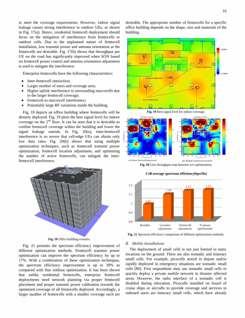
densely deployed. Fig. 19 plots the best signal level for indoor
coverage on the 2nd
floor. It can be seen that it is desirable to
confine femtocell coverage within the building and lower the
signal leakage outside. In Fig. 20(a), inter-femtocell
interference is so severe that cell-edge UEs can obtain only
low data rates. Fig. 20(b) shows that using multiple
optimization techniques, such as femtocell transmit power
optimization, femtocell location adjustment, and optimising
the number of active femtocells, can mitigate the inter-
femtocell interference.
Fig. 18 Office building scenario.
Fig. 21 presents the spectrum efficiency improvement of
different optimization methods. Femtocell transmit power
optimization can improve the spectrum efficiency by up to
17%. With a combination of these optimization techniques,
the spectrum efficiency improvement is up to 39% as
compared with that without optimization. It has been shown
that unlike residential femtocells, enterprise femtocell
deployments need network planning via proper femtocell
placement and proper transmit power calibration towards the
optimized coverage of all femtocells deployed. Accordingly, a
larger number of femtocells with a smaller coverage each are
desirable. The appropriate number of femtocells for a specific
office building depends on the shape, size and materials of the
building.
Fig. 19 Best signal level for indoor coverage.
Fig. 20 User throughput map between w/o optimization.
Fig. 21 Spectrum efficiency comparison of different optimization methods.
B. Mobile Installations
The deployment of small cells is not just limited to static
locations on the ground. There are also nomadic and itinerary
small cells. For example, picocells stored in depots and/or
rapidly deployed in emergency situations are nomadic small
cells [80]. First respondents may use nomadic small cells to
quickly deploy a private mobile network in disaster affected
areas. However, the radio interface of a nomadic cell is
disabled during relocation. Picocells installed on board of
cruise ships or aircrafts to provide coverage and services to
onboard users are itinerary small cells, which have already
PL=77dB
Femtocell adjustment
Femtocell
Power optimization
Location adjustment
-30dBm
-120dBm
x coordinate in m
y c
oord
inate
in m
Throughput in bps/Hz
-80 -60 -40 -20 0 20 40 60 80
-60
-40
-20
0
20
40
60
0
0.5
1
1.5
2
x coordinate in m
y c
oord
inate
in m
Throughput in bps/Hz
-80 -60 -40 -20 0 20 40 60 80
-60
-40
-20
0
20
40
60
0
0.5
1
1.5
2
(a): Dense femtocell deployment (b): Multiple optimisation methods
0.8
0.9
1
1.1
1.2
Baseline Location
adjustment
Femtocell
adjustment
Tx power
optimization
Cell average spectrum efficiency(bps/Hz)
0.97
1.08
1.12 1.13

17
found their way into commercial products especially in the
aeronautical and maritime Global System for Mobile
communications (GSM) markets [81]. The radio interface of
an itinerary cell is active on the move.
Nomadic and itinerary small cells also require backhaul
connections to the Public Switched Telephone Network
(PSTN), Public Land Mobile Network (PLMN), or the
Internet. Since these small cells are usually deployed in
remote (e.g., desert, oil rig) or isolated (e.g., aircraft, ship)
areas, their backhaul is currently mainly via satellite links that
are the only communications technology available in remote
or isolated regions [82]. Compared to conventional small cell
backhaul methods such as broadband, the use of satellite
airtime for backhaul is not cost effective at all. In addition,
backhauling voice traffic over geostationary satellites is
subject to a mouth-to-ear delay of approximately 500 ms,
which is not acceptable according to the ITU G.114
recommendation [75].
Fig. 22 VoCeM architecture
In [79], Voice Compression and Enhanced Multiplexing
(VoCeM) was proposed to optimize IuCS voice traffic from
GSM and UMTS picocells and femtocells for satellite
traversal. VoCeM intercepts voice traffic and then reduces its
required satellite bandwidth through RTP multiplexing, header
compression, and transcoding of speech frames, as illustrated
in Fig. In this way, the number of calls that can be transmitted
over a given satellite bandwidth is substantially increased. For
example, a Broadband Global Area Network (BGAN) link has
a typical capacity of 64 kbps, while an Adaptive Multi-Rate
(AMR) 4.75 speech codec consumes a bandwidth of 29.2 kbps
per speech stream. Hence, only two simultaneous voice
streams (i.e. calls) can be served by the BGAN satellite link.
However, VoCeM allows up to 11 voice streams to be
transmitted simultaneously through the satellite link, thereby
not only increasing service offering (i.e. more simultaneous
calls supported) but also reducing the cost of satellite
backhauling.
XII. CONCLUSION
In this paper, a variety of recent topics related to small cell
deployment have be presented, ranging from recent
standardization efforts, SON, CA, MIMO, ICIC, energy
saving techniques, ML approaches, simulation tools and
deployment scenarios. While these topics are by no mean
exhaustive, they collectively represent the current focuses and
what are likely to come in the near future in small cell
deployments.
ACKNOWLEDGMENT
We would like to thank all workshop invited speakers and
attendees. Without them the workshop would not have been
possible. We also thank all previous workshops invited
speakers and attendees, who have helped us improving the
quality of the workshops. We also thank the EU FP7
IAPP@RANPLAN project for the financial support of the
workshop.
REFERENCES
[1] R07-IMT.ADV-C-0002!R1!MSW-E, "Submission and evaluation process and consensus building," ITU-R WP5D, 2008.
[2] ITU-R M.2134, "Requirements related to technical performance for IMT-Advanced radio interface(s)," Nov 2008.
[3] RP-111111, “Updated work item for Carrier based HetNet ICIC for LTE,” 3GPP TSG-RAN Meeting #53, Fukuoka, Japan, 13-16 Sep 2011.
[4] RP-100383, “New work item proposal: enhanced ICIC for non-CA based deployments of heterogeneous networks for LTE,” 3GPP TSG RAN#47, Vienna, Austria, 16-19 March 2010.
[5] RP-111369, “Further enhanced non CA-based ICIC for LTE,” 3GPP TSG RAN Meeting #53, Fukuoka, Japan, 13-16 Sep 2011.
[6] 3GPP TR36.819 V11.1.0 (2011-12), 3rd Generation Partnership Project Technical Specification Group Radio Access Network “Coordinated multi-point operation for LTE physical layer aspects” (Release 11).
[7] 3GPP TS 36.300 V10.3.0 (2011-03), 3rd Generation Partnership Project; Technical Specification Group Radio Access Network; Evolved Universal Terrestrial Radio Access (E-UTRA) and Evolved Universal Terrestrial Radio Access Network (E-UTRAN); Overall description; Stage 2 (Release 10).
[8] RP-120279, “Updates to SID: further enhancements for HNB and HeNB,” 3GPP TSG RAN meeting #55, Xiamen, China, 28 Feb-3 Mar 2012.
[9] RP-110709, “Revised WID on study on HetNet mobility enhancements for LTE,” 3GPP TSG RAN Meeting #52, Bratislava, Slovakia, 31 May 31-3 June 2011.
[10] 3GPP TR 36.913, “Requirements for further advancements for evolved Universal Terrestrial Radio Access (E-UTRA) (LTE-Advanced),” Dec
2009.
[11] M. Iwamura, K. Etemad, M. Fong, R. Nory, and R. Love, “Carrier aggregation framework in 3GPP LTE-Advanced,” IEEE Commun. Mag.,
vol. 48, no. 8, pp. 60–67, Aug 2010.
[12] S. Abeta, “Toward LTE commercial launch and future plan for LTE enhancements (LTE-Advanced),” IEEE International Conf. Commun.
Systems (ICCS), pp. 146–150, Singapore, 17-19 Nov 2010.
[13] L. Garcia, K. Pedersen, and P. Mogensen, “Autonomous component carrier selection for local area uncoordinated deployment of LTE-
Advanced,” IEEE Vehicular Tech. Conf. Fall (VTC 2009-Fall), pp. 1–5,
Anchorage, USA, 20-23 Sep 2009. [14] ——, “Autonomous component carrier selection: interference
management in local area environments for LTE-Advanced,” IEEE
Commun. Mag., vol. 47, no. 9, pp. 110–116, 2009. [15] L. Zhang, L. Yang, and T. Yang, “Cognitive interference management
for LTE-A femtocells with distributed carrier selection,” IEEE Vehicular
Tech. Conf. Fall (VTC 2010-Fall), Ottawa, Canada, 6-9 Sep 2010. [16] Y. Yan, A. Li, X. Gao, and H. Kayama, “A new autonomous component
carrier selection scheme for home eNB in LTE-A system,” IEEE
Vehicular Tech. Conf. Spring (VTC 2011-Spring), Budapest, Hungary, 15-18 May 2011.
[17] S. Uygungelen, Z. Bharucha, and G. Auer, “Decentralized interference
coordination via autonomous component carrier assignment,” IEEE Global Telecom. Conf. (GLOBECOM), Houston, USA, 5-9 Dec 2011.
[18] D. Lopez-Perez, I. Gu , G. de la Roche, M. Kountouris, T. Q.
Quek, and J. Zhang, “Enhanced inter-cell interference coordination challenges in heterogeneous networks,” IEEE Wireless Commun. Mag.,
Jun 2011.

18
[19] Qualcomm Incorporated, “LTE advanced: heterogeneous networks,”
White Paper, Feb 2010. [20] NTT DOCOMO, “Performance of eICIC with control channel coverage
limitation,” R1-103264, 3GPP Std., Montreal, Canada, May 2010.
[21] D. Lopez-Perez and X. Chu, "Inter-cell interference coordination for expanded region picocells in heterogeneous networks," International
Conf. Computer Commun. and Networks (ICCCN), 31 Jul-4 Aug 2011.
[22] J. G. Andrews, W. Choi, and R. W. Heath, “Overcoming interference in spatial multiplexing MIMO cellular networks,” IEEE Trans. Wireless
Commun., Dec 2007.
[23] A. Ghosh, R. Ratasuk, B. Mondal, N. Mangalvedhe, and T. Thomas, “LTE-Advanced: next-generation wireless broadband technology,”
IEEE Trans. Wireless Commun., Jun 2010. [24] J. C. Ikuno, M. Wrulich, and M. Rupp, “System level simulation of LTE
networks,” IEEE VTC Spring, May 2010.
[25] K. Beh, A. Doufexi, and S. Armour, “On the performance of SU-MIMO
and MU-MIMO in 3GPP LTE downlink,” IEEE PIMRC, Sep 2009. [26] Z. Bai, C. Spiegel, G. H. Bruck, P. Jung, M. Horvat, J. Berkmann, C.
Drewes, and B. Gunzelmann, “On the physical layer performance with
rank indicator selection in LTE/LTE-Advanced system,” IEEE PIMRC, Sep 2010.
[27] M. Simsek, T. Akbudak, B. Zhao, and A. Czylwik, “An LTE femtocell
dynamic system level simulator,” International ITG Workshop on Smart Antennas, Feb 2010.
[28] V. Chandrasekhar, M. Kountouris, and J. Andrews, “Coverage in multi-
antenna two-tier networks,” IEEE Trans. Wireless Commun., Oct 2009. [29] T.-H. Kim and T.-J. Lee, “Throughput enhancement of macro and femto
networks by frequency reuse and pilot sensing,” IEEE IPCCC, Dec 2008.
[30] G. Boudreau, J. Panicker, N. Guo, R. Chang, N. Wang, and S. Vrzic,
“Interference coordination and cancellation for 4G networks,” IEEE Commun. Mag., Apr 2009.
[31] S. H. Ali and V. C. M. Leung, “Dynamic frequency allocation in
fractional frequency reused OFDMA networks,” IEEE Trans. Wireless Commun., Aug 2009.
[32] 3GPP TS 36.213, Evolved Universal Terrestrial Radio Access (E-
UTRA) Physical Layer Procedures (Release 8), Sep 2009. [33] 3GPP TR 36.921, Home eNodeB (HeNB) Radio Frequency (RF)
Requirements Analysis (FDD), 3GPP, March 2010.
[34] 3GPP TR 36.814, Further Advancements for E-UTRA Physical Layer
Aspects (Release 9), 3GPP, March 2010.
[35] D. S. Baum, J. Hansen, G. D. Galdo, M. Milojevic, J. Salo, and P. Kysti,
“An interim channel model for beyond-3G systems extending the 3GPP spatial channel model (SCM),” IEEE VTC Spring, May 2005.
[36] K. Ramadas and R. Jain, “WiMAX system evaluation methodology,”
WiMAX Forum Tech. Rep., Jan 2007. [37] M. Maqbool, M. Lalam, and T. Lestable, “Comparison of femto cell
deployment models for an interference avoidance technique,” Proc.
Future Network and Mobile Summit, Warsaw, Poland, 2011. [38] G. Fettweis and E. Zimmermann, “ICT energy consumption - trends and
challenges,” IEEE Wireless Personal Multimedia Commun. Conf., Sep
2008. [39] Y. Chen, S. Zhang, S. Xu and G.Y. Li, “Fundamental trade-offs on
green wireless networks,” IEEE Commun. Mag., vol. 49, pp. 30-37, Jun
2011. [40] C. Xiong, G.Y. Li, S. Zhang, Y. Chen and S. Xu, “Energy- and spectral-
efficiency tradeoff in downlink OFDMA networks,” IEEE Trans.
Wireless Commun., vol. 10, pp. 3874–3885, Nov 2011.
[41] W. Guo and T. O'Farrell, “Capacity-energy-cost tradeoff for small-cell
networks,” IEEE Vehicular Tech. Conf. GreeNet Workshop, May 2005.
[42] A. Furuskar, et. al., “An infrastructure cost evaluation of single- and multi-access networks with heterogeneous traffic density,” IEEE
Vehicular Tech. Conf., May 2005.
[43] 3GPP TR 36.814 v9.0.0 “Further advancements for E-UTRA physical layer aspects (Rel. 9),” 3GPP Technical Report, Mar 2010.
[44] G. Auer, et. al. “Cellular energy efficiency evaluation framework,”
IEEE Vehicular Tech. Conf. Spring, pp. 1-6, May 2011. [45] A Fehske, G. Fettweis, J. Malmodin and G. Biczok, "The global
footprint of mobile communications: The ecological and economic
perspective," IEEE Commun. Mag., vol.49, no.8, pp.55-62, Aug 2011. [46] S. Verdu, "Spectral efficiency in the wideband regime," IEEE Trans.
Information Theory, vol.48, no.6, pp.1319-1343, Jun 2002.
[47] F. Meshkati, H. V. Poor, S. C. Schwartz and N. B. Mandayam, "An energy-efficient approach to power control and receiver design in
wireless data networks," IEEE Trans. Commun., vol. 53, no. 11, pp.
1885-1894, Nov 2005.
[48] E. Calvanese Strinati, A. De Domenico and A. Duda, "Ghost femtocells: A novel radio resource management scheme for OFDMA based
networks," IEEE WCNC, pp.108-113, Mar 2011.
[49] E. Calvanese Strinati and P. Greco, "Green resource allocation for OFDMA wireless cellular networks," IEEE PIMRC, pp. 2775-2780, Sep
2010.
[50] G. Auer, V. Giannini, I. G´odor, P. Skillermark, M. Olsson, M.A. Imran, D. Sabella, M.J. Gonzalez, C. Desset, O. Blume and A. Fehske, “How
much energy is needed to run a wireless network?” IEEE Commun.
Mag., vol. 18, no. 5, pp. 40-49, Oct 2011. [51] Y. Chen, S. Zhang, and S. Xu, “Characterizing energy efficiency and
deployment efficiency relations for green architecture design,” IEEE
ICC WS, pp. 1–5, 2010. [52] I. Ashraf, F. Boccardi, and L. Ho, “Sleep mode techniques for small cell
deployments,” IEEE Commun. Mag., vol.49, no.8, pp.72-79, Aug 2011.
[53] P. Frenger, P. Moberg, J. Malmodin, Y. Jading, and I. Godor, “Reducing energy consumption in LTE with cell DTX,” IEEE VTC Spring 2011,
pp. 1–5, May 2011.
[54] R. Gupta and E. Calvanese Strinati, “Base-station duty-cycling and traffic buffering as a means to achieve green communications,” IEEE
Vehicular Tech. Conf., Québec City, Canada, 3-6 Sep 2012.
[55] C. Prehofer and C. Bettstetter, “Self-organization in communication
networks: principles and design paradigms,” IEEE Commun. Mag., vol.
43, no. 7, pp. 78–85, July 2005.
[56] P. Clark, Machine Learning: Techniques and Recent Developments, in
A. R. Mirzai (ed.), Artificial Intelligence: Concepts and Applications in
Engineering, Chapman and Hall, London, UK, 1990.
[57] K. P. Sycara, “Multiagent systems,” AI Magazine, vol. 19, no. 2, pp. 79–
92, 1998.
[58] R. S. Sutton and A. G. Barto, Reinforcement Learning: An Introduction,
the MIT Press, 1998.
[59] A. Galindo-Serrano, L. Giupponi, and G. Auer, “Distributed femto-to-
macro interference management in multiuser OFDMA networks,” IEEE
VTC 2011-Spring WS, Budapest, Hungary, 15-18 May 2011.
[60] L. Giupponi, A. Galindo-Serrano, P. Blasco and M. Dohler, “Docitive
networks – an emerging paradigm for dynamic spectrum management,”
IEEE Wireless Commun. Mag., vol. 17, no. 4, pp. 47 - 54, Aug 2010.
[61] A. Galindo-Serrano, L. Giupponi and M. Majoral, “On implementation
requirements and performances of Q-learning for self-organized
femtocells,” IEEE GLOBECOM WS FEMnet, Dec 2011.
[62] P. S. Sastry, V. V. Phansalkar and M. A. L. Thathachar, “Decentralized
learning of Nash equilibria in multi-person stochastic games with
incomplete information,” IEEE Trans. Systems, Man and Cybernetics,
24(5), pp. 769-777, 1994.
[63] S. M. Perlaza, H. Tembine, and S. Lasaulce, “How can ignorant but
patient cognitive terminals learn their strategy and utility?” IEEE Intl.
Workshop on Signal Processing Advances for Wireless Commun.
(SPAWC), Marrakesh, Morroco, Jun 2010.
[64] M. Bennis and S. M. Perlaza, “Decentralized cross-tier interference
mitigation in cognitive femtocell networks,” IEEE ICC, Kyoto, Japan,
Jun 2011.
[65] M. Bennis, S. M. Perlaza and M. Debbah, “Learning coarse correlated
equilibrium in two-tier wireless networks,” IEEE ICC’12, Ottawa,
Canada, Jun 2012.
[66] L. Rose, S. M. Perlaza, S. Lasaulce and M. Debbah, “Learning equilibria
with partial information in wireless networks," IEEE Commun. Mag.,
vol. 49, no. 8, Aug 2011.
[67] A. Feki and V. Capdevielle, “Autonomous resource allocation for dense
LTE networks: a Multi-Armed Bandit formulation”, IEEE PIMRC, Sep
2011.
[68] A. Feki, V. Capdevielle and E. Sorsy, “Self-organized resource allocation for LTE pico cells: a reinforcement learning approach,” IEEE
VTC 2012 Spring, 2012.
[69] A. De Domenico, R. Gupta, and E. Calvanese Strinati, “Dynamic traffic management for green open access femtocell networks,” IEEE Vehicular
Tech. Conf., Yokohama, Japan, 6-9 May 2012.
[70] 3GPP TSG-RAN1 #48, Orange Labs, China Mobile, KPN, NTT DoCoMo, Sprint, T-Mobile, Vodafone, and Telecom Italia, “R1-070674,
LTE physical layer framework for performance verification,” St Louis,
USA, Feb 2007. [71] K. Norlund, T. Ottosson, and A. Brunstrom, “Fairness measures for best
effort traffic in wireless networks,” IEEE PIMRC, vol. 4, pp. 2953–

19
2957, Sep 2004.
[72] 3GPP TSG-RAN4 #51, Alcatel-Lucent, picoChip Designs, and Vodafone, “R4-092042, Simulation assumptions and parameters for
FDD HENB RF requirements,” May 2009.
[73] ns-3 Simulator, http://www.nsnam.org/. [74] 3GPP TS 36.322, E-UTRA Radio Link Control (RLC) protocol
specification.
[75] ITU-T G.114 Series G: Transmission systems and media, digital systems and networks, “International telephone connections and circuits –
General Recommendations on the transmission quality for an entire
international telephone connection”. [76] 3GPP TS 36.101, UE radio transmission and reception.
[77] J. Zhuang et al., IEEE 802.16m Evaluation Methodology Document
(EMD), IEEE802.16 Broadband Wireless Access Working Group, 2008. [78] 3GPP TS 36.323, E-UTRA Packet Data Convergence Protocol (PDCP)
specification.
[79] VoCeM – Voice Compression and Enhanced Multiplexing. http://triagnosys.com/vocem/
[80] A. Via and M. Werner, “Portable satellite backhauling solution for
emergency communications,” 5th Advanced Satellite Multimedia Systems (ASMS) Conf., Cagliari, Italy, Sep 2010.
[81] GSMConneX – GSM and Wifi Connectivity for Aircraft.
http://triagnosys.com/gsmconnex-aero/ [82] A. Via and M. Werner, “Satellite communications for management of
mass casualty incidents: the e.Triage project,” 28th AIAA International
Commun. Satellite Systems Conf. (ICSSC), Anaheim, California, Sep 2012.