small oscillating steam engine - plans for...
TRANSCRIPT

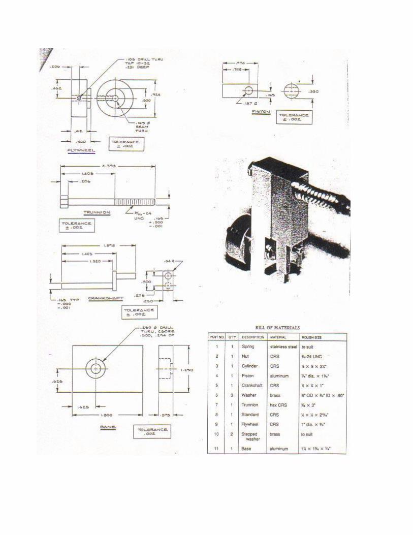
Small Oscillating Steam Engine
Here are some plans for a model oscillating steam engine. We've
build several of them with decent but unspectacular results.
Notes on this engine: It's not our favorite design....students have
more trouble with these oscillators than the valve-type engines,
because parts must fit more precisely...but they are pretty simple.
We wouldn't make a one-piece crank. When we made this engine we
used 1/8" gas welding rod for the round parts of the
crankshaft...we silver soldered the pieces to a small plate with two
1/8" holes drilled in it (.276" apart)....bought low temperature
"silver solder" from Home Depot (or try a hardware store)....works
fine using a propane torch. One of our guys made a similar engine
and he used "Crazy Glue" to hold the 1/8" rods to the plate! Also
worked fine. Even though the crank in the drawing shows a "0.165
typ" pin, the piston hole to recieve it is 0.187". I assume this is a
mistake in the print. We made it all 1/8" and it worked fine. The
0.165 reamed hole is intended to allow the 3/16-24 bolt to have a
"perfect fit" with no slop. We didn't have any of these bolts on
hand so we just used a #10-24 bolt. We measured the outside
diameter of the bolt and drilled a hole that would allow the bolt to
fit....we didn't use a ream. Can't recall the drill size we
used....but as long as the bolt fits without too much "slop", it'll
work. The idea of using a "perfect reamed" hole is a fussy detail
that really isn't needed in these engines. Make sure to use a
lightweight spring.....a strong one will add too much friction,
especially if it is adjusted tight. You can make the slot in the
cylinder bottom without a mill if you're careful. Drill a 1/4" hole
into the cylinder 1.525 down from the top until it breaks into the
bore....then carefully hacksaw out the piece and file it smooth.
After drilling the bore, if a reamer isn't available, you can "hone
out" the hole with a piece of sandpaper attached to a wooden
dowel....spin the dowel in a power drill using a bit of oil. To make a

piston that is "sized" to the correct diameter, you can get a piece
of steel or brass stock (about 4" long) and "turn it down" by holding
a file against it, while it is spinning in a power drill....keep checking
to see if it will slide in the bore...when it does, you're finished.
Then, just cut off the end of it for your piston. There is a "step" in
the main frame part (called the "standard") that is 0.413 up from
the base. You can "rough grind" this out with a small grinding wheel
or Dremel tool and then file it to size....it takes patience, but it
can be done. Probably the most important part of this engine is the
positions of the air passage holes and the pivot point (where we used
a 10-24 bolt). If these positions aren't correct, the thing won't
run. We've been very successful making these holes with a hand-
held electric power drill, as long as we have accurate center punched
marks first. We found the flywheel on this engine to be a bit
small...made the "standard" a bit taller for flywheel clearance and
used a piece of 2" round aluminum. The bigger flywheel allows it to
idle at a lower speed. You can "lap" the sliding surfaces of the
"standard" and the cylinder together with toothpaste.....if these
surfaces aren't smooth against each other, the motor will run
poorly. Sometimes these engines won't start up right away due to a
tiny flaw....engine must spin pretty freely to run. To help "break in"
the engines, we hold the flywheel of the assembled engine against a
buffing wheel....let the engine spin this way for several minutes until
it spins nice and free. Usually, we try about 10 psi to get the engine
running. They usually won't run on less than 5 psi, but some need as
much as 40 psi at first, until fully broken in. Make sure engine is
well lubricated in light oil. Wear safety glasses....they can blow
apart if components fail!

Oscillating Model Steam Engine (source: unknown)