smart box iii instruction manual - onyx valve · smart box iii instruction manual ... seal flush...
TRANSCRIPT

1
Smart Box III
Instruction Manual
Introduction: The Smart Box is designed to interface with progressing cavity pumps. This latest generation Smart Box is versatile, easy to install, and easy to use. The Smart Box provides simple, direct communication between the plant operators and progressing-cavity pumps. The Smart Box prevents lost production and down time by ensuring that pumps remain within proper operating limits. NOTE: In order to insure safe, reliable operation, the Onyx Smart Box MUST be used only with a genuine Onyx Isolator Ring. Only the genuine Onyx Isolator Ring enables this control system to work reliably on viscous fluids, suspended solids, abrasive, corrosive, and volatile liquids. Connecting the Onyx Smart Box to isolator rings made by other manufacturers compromises safety, reliability, and VOIDS ALL WARRANTIES AND TECHNICAL SUPPORT. Progressing cavity pumps handle an incredible range of viscous and abrasive fluids; however, they are susceptible to damage from three factors:
1. High pressure over the design limit can burst the discharge end of the pump, stall or burn out the motor, or break the universal joints.
2. Run dry conditions interrupt the flow of liquid the pump needs to dissipate frictional
heat, melting the stator.
3. Seal flush failure burns up the shaft seal causing the stuffing box to leak. Some pumps use the process fluid to cool the stuffing box, so your pump may or may not need an external seal flush system. Refer to the pump manufacturer’s instruction sheet to see if your particular pump needs an external seal water flush.

2
If an external flush is required but has not been provided, a complete seal water kit is available from Onyx Valve Company. This seal water kit is designed to interface with your pump and the Smart Box. Contact our factory for details.
How It Works:
The Smart Box provides a closed-loop system of protection to safeguard the pump. The elements of the loop include:
1. Progressing Cavity pump 2. Onyx isolator Ring on pump discharge 3. A 2-point pressure switch 4. Smart Box 5. A VFD or Motor Starter 6. Motor
Pressure Switch 2-Point
F 3 F 4
FLOW
SMART BOX
F 1
SuctionDischarge
M
Go / No-Go signal
VFD
Motor
ONYX VALVECINNAM INS ON NJ 0 80 77P H: 6 0 9-8 29-2 88 8
P-C PUMP
3 PHASEPOWER
Onyx Isolator Ring
Smart Box General ArrangementClosing the Loop
PUMP RE ADY
F 2
Remote SCADDA
System
In order to protect the pump properly, the Smart Box needs three things:
1. It has to monitor the pressure at the pump discharge.
2. It has to know when the pump is running
3. It has to have final authority to stop the pump if it detects a malfunction condition.

3
Sequence of Operation: The Smart Box Touch Screen communicates information to the plant operator in plain English:
1. No electrical power to the Smart Box: a. OUTPUT-501 Open circuit. Blocks pump from starting.
2. If: Smart Box and pump have power available, and pump is off and in its normal state, a. Touch screen display reads:
i. PUMP IS READY. ii. PRESS F2 TO START
1. This feature can be disabled in the field if desired. b. The pump can be started by activating the VFD or Motor Starter or pressing F2.
3. If the pump is running, and everything is normal,
a. Touch screen display reads: i. PUMP IS RUNNING.
ii. Press F1 for E-STOP.
4. Every time the pump starts: a. at Time = 0.0 seconds:
i. Smart box interrogates High Pressure Switch. 1. If the discharge pressure exceeds safe limit, Smart Box shuts
down pump immediately, and 2. Touch screen will read:
a. HIGH PRESSURE FAULT b. PRESS F3 TO RE SET
b. at Time = 90 seconds:
i. Smart box interrogates Low Pressure Switch. 1. If the pump looses prime the Smart Box will shut down the
pump immediately, and 2. Touch screen will read:
a. RUN DRY FAULT b. PRESS F3 TO RE SET
c. At Time = ANY:
i. Smart box interrogates F1 (E-STOP function). 1. If Plant Operator presses F1: 2. Pump will stop and remain locked out 3. Touch screen will read:
a. LOCAL E-STOP b. PRESS F3 TO RE SET

4
Neutral
N.O.
SMARTBOX
Internal Logic
M
120 VAC
RemoteStop
RemoteStart
3 PHASEPOWERTO PUMP
MOTOR
StopStart
CONTACTOR
THERMAL OL
SCADAsystem
General Arrangement
2-1/2
10
8
5
2
3
4
6
1
2.81
2.25
2.25
2.25
1.87
1.87
1.87
2.12
1.87
B
1.87
24
14
16
18
20
3.12
3.12
3.12
3.12
3.12
1-1/2
SIZE
01 0
-15 to +15 psi
0 - 60 psi
RANGE:
0 - 150 psi
0 - 600 psi
FILL FLUID:
ØA
NO
TITLE :
YES
F4F3F2F1
PUMP READY
SMART BOX
(2) 3/4 NPT CONDUIT CONN.
2.75
13.25
10.87
7.62
4.00
5.25
8.62
6.75
4.75
3.25
ØA
2.50
ACETAL
CENTER MATERIAL:
END PLATE MATERIAL:
316 STAINLESS STEEL
28.12
316 STAINLESS STEELCARPENTER 20 STAINLESS STEEL
CARBON STEEL
23.75
17.62
20.12
21.50
Pressure SwitchAllen-Bradley 2-PointPNP configurationHousing: 316 Stainless steelEnclosure: IP-66Voltage: 12 --> 30 VDCMax Load: 250 mAAccuracy: +- 0.5% of range
7
B
LOCAL ALARM OPTION:
NEMA-4X ENCLOSURE
MICRO PROCESSEDBASED PLC LOGIC
ONYX VALVEPRESSURE SENSOR W/ IFM PRESSURE SWITCH
& SMART BOX
SIGNAL LIGHTS (4)
SLEEVE ELASTOMER:
SPECIFICATIONS:
ELECTRICAL RATING:
FDA SILICONE (-20° F TO 400° F)
TEFLON
SILICONE (STD) (-40° F TO 400° F)
CONTACT RATING:
1PH/60HZ/115 VOLT POWER REQUIREDPOWER CONSUMPTION 30VA
6
12 16.00 3.12
4 X Ø .312 THRU
Standard Cord = 10 m long
TUBE I .D.MATCHES SCH. 40 CARBON STEELPIPE
250 VAC, 10A RESISTIVE
11
10.50
STURDY MOUNTINGFOR HEAVY OR MULTIPLE INSTRUMENTS
CINNAM INSON N J08077PH: 609-829-2888
ONYX VALVE
Display can be rotated to face any
direction
SENSOR FITSINSIDE BOLT PATTERN OF MATING FLANGES
CARPENTER 20 STAINLESS STEEL
6
9
Power consumption = ¼ Amp @ 120 VAC / 60~ Operating Modes: There are several ways to ensure that these three conditions are met. The first decision you have to make is the Operating Mode. There are three possible operating modes: 1. Master Control Mode with Fixed Speed pump:
All START and STOP commands (manual and automatic) are routed to the Smart Box, and the Smart Box is the only device that starts and stops the pump. If you elect to use this mode, it is imperative that there are no other devices in the system that can start the pump.
5
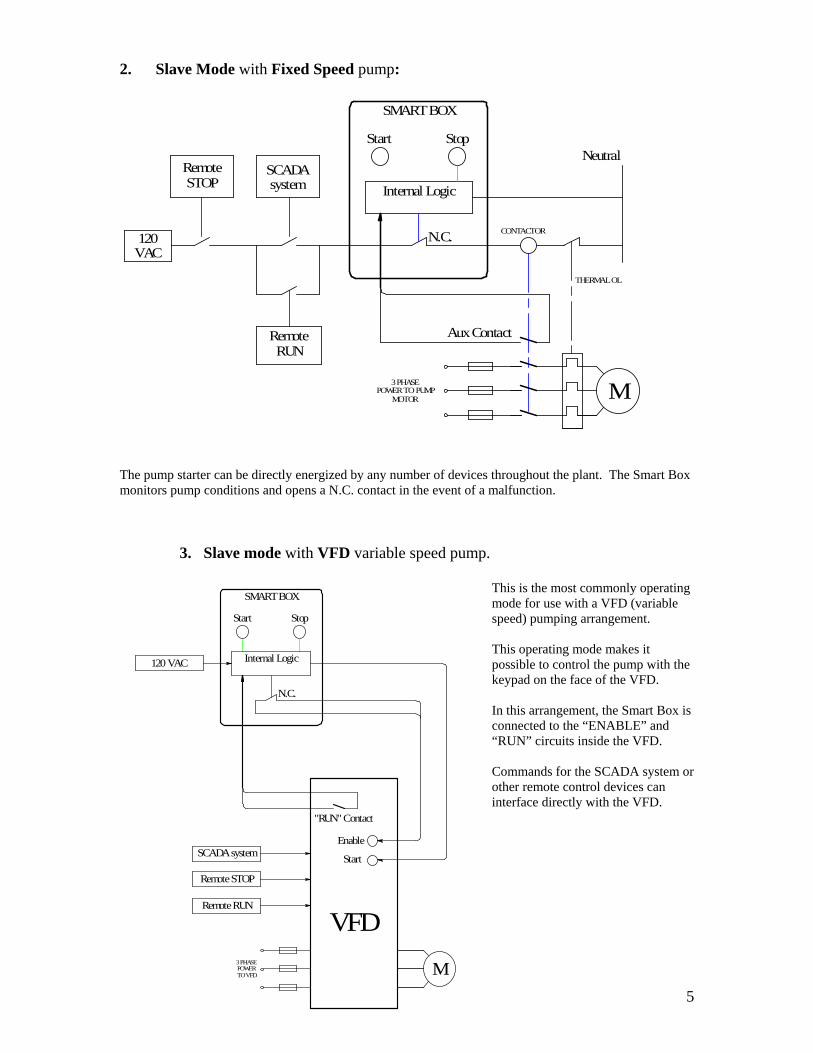
2. Slave Mode with Fixed Speed pump:
Aux Contact
3 PHASEPOWERTO PUMP
MOTOR
SMARTBOX
M
Start Stop
Internal Logic
N.C.
Neutral
THERMAL OL
CONTACTOR120 VAC
Remote STOP
SCADA system
Remote RUN
The pump starter can be directly energized by any number of devices throughout the plant. The Smart Box monitors pump conditions and opens a N.C. contact in the event of a malfunction.
3. Slave mode with VFD variable speed pump.
This is the most commonly operating mode for use with a VFD (variable speed) pumping arrangement. This operating mode makes it possible to control the pump with the keypad on the face of the VFD. In this arrangement, the Smart Box is connected to the “ENABLE” and “RUN” circuits inside the VFD. Commands for the SCADA system or other remote control devices can interface directly with the VFD.
N.C.
M
SMARTBOX
Start Stop
Internal Logic
Enable
"RUN" Contact
SCADAsystem
RemoteRUN
3 PHASEPOWER TO VFD
VFD
120 VAC
Start
RemoteSTOP

6
PRINCIPLE OF OPERATION
In order for the Smart Box to protect pumps from over pressure and run dry conditions, a 2-stage pressure switch is installed at the pump discharge. Set the high pressure switch to the highest safe operating pressure for the process system. If discharge pressure exceeds the high pressure setting, the Smart Box stops the pump and displays a "High Trip" message on the front of the control box. The pump remains stopped until “Reset" button (F3) is pressed. The Smart Box will not allow the pump to restart until excess discharge pressure has been relieved. This system also protects pumps against run dry damage by monitoring the discharge pressure. To set the low pressure switch, it is necessary to understand the differences between static pressure, friction pressure, and total pressure. Static pressure is caused by elevation differences in the discharge pipe. It is the direct result of the weight of the liquid in the piping system. This pressure is present even when the pump is idle. Static pressure is not influenced by pipe size, number of fittings, or viscosity. Static pressure is determined solely by fluid density and the difference in height between the pressure switch and the outlet of the pipe. In the example shown here, the outlet of the discharge pipe is 10 feet higher than the gauge, so static head is 10 feet (which equals 4.3 psi). Friction pressure is caused by the flow of liquid through a pipe and is present only when the pump is primed and running. It depends on flow rate, size and length of pipe, roughness of the inside of the pipe, number of fittings, and fluid viscosity.
P-C PUMPM
Onyx Isolator Ring
10
0
ft H2O
Static PressureNO
FLOW
10 ft
10 ft
M
0
Onyx Isolator Ring
P-C PUMP
Total Pressure MAX FLOW
2010
15
ft H2O30

7
Total pressure = Static Pressure + Friction Pressure. Total pressure can be observed directly by reading the discharge gauge when the pump is running. When the pump is idle, the gauge shows static pressure. When the pump is running with flow present, the gauge shows total pressure. In the example, total pressure is 20 psi. For run dry protection, the low-pressure switch should be set midway between the static and total pressure. In our example the correct setting for the low-pressure switch is 15 psi. When the pump is running correctly, the low-pressure switch signals that flow is present. If the pump runs dry and flow stops, pressure falls back to the static pressure. This causes the low-pressure switch to signal that flow has stopped. The Smart Box program allows the pump time to prime. Each time the pump starts, the Smart Box waits 90 seconds before checking for run dry conditions. After this time-out period, if the pressure falls below the low-pressure setting (which indicates the pump is running dry) the Smart Box stops the pump and displays a "Low Trip" message. The "Low Trip" state remains until the "Reset" button (F3) is pressed.
Wiring
A qualified electrician should perform wiring. All wiring should conform to national and local electrical codes. Disconnect all electric power to this box before wiring or servicing.
Note: You do not need a separate H-O-A (Hand - Off – Auto) switch or a Reset push button near the Smart Box. The Smart box is pre-programmed to perform these functions.
8
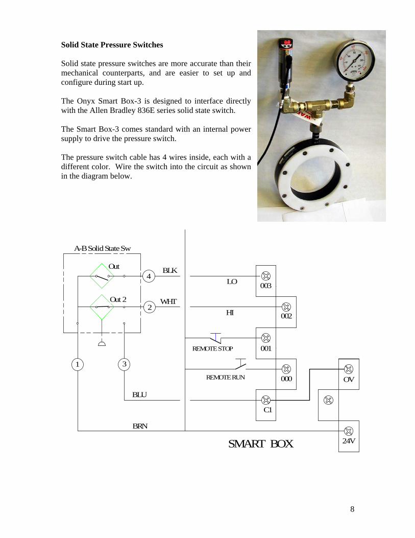
Solid State Pressure Switches Solid state pressure switches are more accurate than their mechanical counterparts, and are easier to set up and configure during start up. The Onyx Smart Box-3 is designed to interface directly with the Allen Bradley 836E series solid state switch. The Smart Box-3 comes standard with an internal power supply to drive the pressure switch. The pressure switch cable has 4 wires inside, each with a different color. Wire the switch into the circuit as shown in the diagram below.
000
001
HI 002
REMOTE STOP
REMOTE RUN OV
BLK
WHT
LO003
24VSMART BOX
C1
Out
31
A-B Solid State Sw
4
2
BRN
BLU
Out 2
9
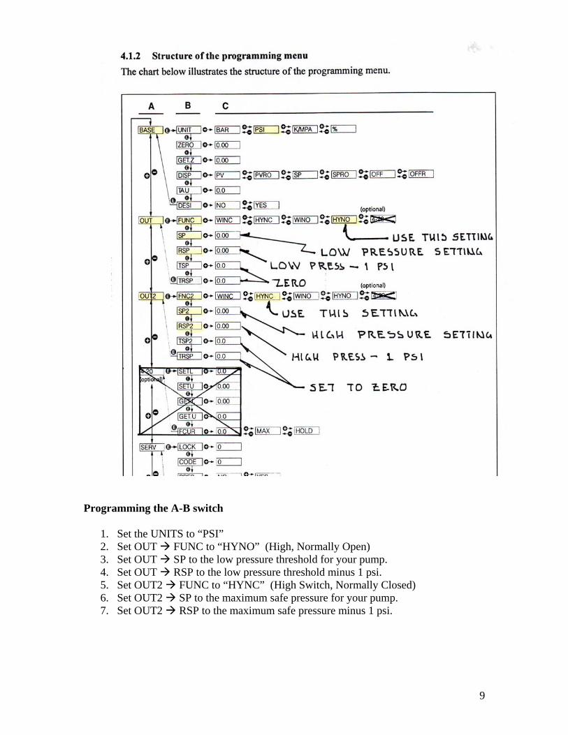
Programming the A-B switch
1. Set the UNITS to “PSI” 2. Set OUT FUNC to “HYNO” (High, Normally Open) 3. Set OUT SP to the low pressure threshold for your pump. 4. Set OUT RSP to the low pressure threshold minus 1 psi. 5. Set OUT2 FUNC to “HYNC” (High Switch, Normally Closed) 6. Set OUT2 SP to the maximum safe pressure for your pump. 7. Set OUT2 RSP to the maximum safe pressure minus 1 psi.

10
1. Master Control with fixed speed pump:
HI TRIP ALARM
LO TRIP ALARM
3 PHASEPOWER TO
PUMPMOTOR
CONTACTOR
503
502
C4
501
C3
005
JUMPER
JUMPER
NO SEAL FLUSH007
C
SEALFLOWSWITCH
NO
DISABLE LOCAL START
NOC
LONCC
003
OV
SMART BOX
L
N
24V
REMOTERUN
001REMOTESTOP
M
C1
120 VAC, 60HZHOT
NEUTRAL
1
43
2
000
002
006
004
THERMAL OL
SEAL FLUSH FAILUREALARM
500HI
504
REMOTE RESET
008
OUTPUTSINPUTS
009 505
SEAL FLUSHSOLENOID VALVE
TERMINALSTRIP
Terminal Comments (Master Mode)
TB-1
Connect 120 VAC / 60~ (hot) to #1 on the power strip.
TB-2 If you want to operate the motor starter (and optional seal flush solenoid valve) with the same 120 V that you are using to power the Smart Box, install a jumper wire between TB-2 and #C3.
TB-3 Connect Neutral to #3 on the power strip.
TB-4 This terminal provides a neutral point for the motor starter and solenoid valve.

11
Inputs: NOTE: All Input signals MUST be powered from terminal “24V” on the Smart Box PLC as shown in schematic #1 above.
000 You can connect an (optional) remote RUN switch to terminal # 000
001 You can connect an (optional) remote STOP button to terminal #001. If you do not connect a STOP button, you must install a jumper wire between “24V” and terminal #001.
002 You must connect the High Pressure Switch (N.C. contact) to terminal #002.
003 You must connect the Low Pressure Switch (N.O. contact) to terminal #003.
004 If you have a seal flush flow switch, wire it to terminal #004.
005 Not used.
006 Disable Local Start. The Smart Box includes a START button (F2) on the front panel. This START button is functional if you leave terminal #006 naked. If you install a jumper wire between 24V and #006, this will disable the START button.
007 If you do NOT have a seal flush flow switch, then you MUST install jumper wire to terminal #007.
008 If the Smart Box goes into an alarm state, it will block all attempts to restart the pump until you perform a reset. You can manually reset the alarm by pressing the Reset button (F3) on the front panel, or can do a remote reset by applying a momentary pulse to #008.
009 Not used.
Outputs:
C3 Apply power for the pump starter to C3.
C4 Apply power for Alarm circuits and (optional) seal flush system to terminal #C4.
500 Connect to pump motor starter. This circuit closes to operate the pump.
501 Not used in this mode.
502 Run Dry Alarm signal
503 High Pressure Alarm signal
504 Seal Flush Fail Alarm signal
505 Solenoid valve connection.
12
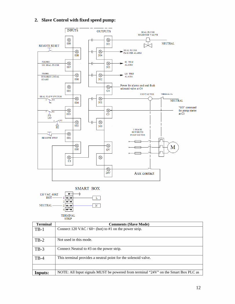
2. Slave Control with fixed speed pump:
Terminal Comments (Slave Mode)
TB-1
Connect 120 VAC / 60~ (hot) to #1 on the power strip.
TB-2 Not used in this mode.
TB-3 Connect Neutral to #3 on the power strip.
TB-4 This terminal provides a neutral point for the solenoid valve.
Inputs: NOTE: All Input signals MUST be powered from terminal “24V” on the Smart Box PLC as
13
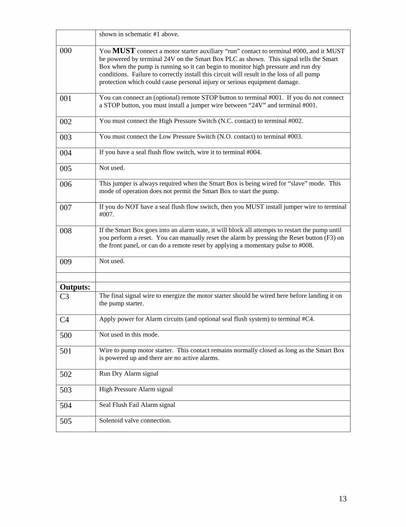
shown in schematic #1 above.
000 You MUST connect a motor starter auxiliary “run” contact to terminal #000, and it MUST be powered by terminal 24V on the Smart Box PLC as shown. This signal tells the Smart Box when the pump is running so it can begin to monitor high pressure and run dry conditions. Failure to correctly install this circuit will result in the loss of all pump protection which could cause personal injury or serious equipment damage.
001 You can connect an (optional) remote STOP button to terminal #001. If you do not connect a STOP button, you must install a jumper wire between “24V” and terminal #001.
002 You must connect the High Pressure Switch (N.C. contact) to terminal #002.
003 You must connect the Low Pressure Switch (N.O. contact) to terminal #003.
004 If you have a seal flush flow switch, wire it to terminal #004.
005 Not used.
006 This jumper is always required when the Smart Box is being wired for “slave” mode. This mode of operation does not permit the Smart Box to start the pump.
007 If you do NOT have a seal flush flow switch, then you MUST install jumper wire to terminal #007.
008 If the Smart Box goes into an alarm state, it will block all attempts to restart the pump until you perform a reset. You can manually reset the alarm by pressing the Reset button (F3) on the front panel, or can do a remote reset by applying a momentary pulse to #008.
009 Not used.
Outputs:
C3 The final signal wire to energize the motor starter should be wired here before landing it on the pump starter.
C4 Apply power for Alarm circuits (and optional seal flush system) to terminal #C4.
500 Not used in this mode.
501 Wire to pump motor starter. This contact remains normally closed as long as the Smart Box is powered up and there are no active alarms.
502 Run Dry Alarm signal
503 High Pressure Alarm signal
504 Seal Flush Fail Alarm signal
505 Solenoid valve connection.

14
3. Monitor Control with VFD variable speed pump. The first thing you have to do prior to wiring a VFD to the Smart Box is to identify the critical interface terminals in the VFD. By way of example, we will use the Allen Bradley model 1336 VFD. Terminal board # TB-2 is shown at the right. The A-B drive comes with (4) programmable relays labeled CR-1 to CR-4. The Smart Box needs one Normally Open “RUN” relay. You can use any available relay for this purpose so long as it is N.O. and can be programmed to energize whenever the pump motor is running. In our example we used CR-1 as the run relay, we will connect terminals #10 and #11 in the A-B drive to the Smart Box. The second step is to identify the relevant terminals on the input side of the VFD. Terminal board TB-3 in the A-B drive is shown at the right. First, we need a “COMMON”, so we could use either terminal #21, 25, or 29. (We used #21 in our sample wiring diagram.) Next, we need an “ENABLE” terminal, which would be #30 in the example A-B drive. Finally, we need a “Run Forward/Stop” terminal, which is #19 in our example. Important note: Just because A-B used these numbers in their 1336 VFD does NOT imply that any other drive will have the same terminal numbering system. It is up to the system engineer to determine the corresponding terminal numbers for what ever brand and model drive they specified. If in doubt call or e-mail the Onyx factory for assistance. Don’t guess at it if you are uncertain or you could wind up smoking the VFD and the Smart Box.

15
Terminal Comments (VFD Mode)
TB-1
Connect 120 VAC / 60~ (hot) to #1 on the power strip.
TB-2 Not used in this mode.
TB-3 Connect Neutral to #3 on the power strip.
TB-4 This terminal provides a neutral point for the solenoid valve.
Inputs: NOTE: All Input signals MUST be powered from terminal “24V” on the Smart Box PLC as shown in schematic #1 above.
000 You MUST connect a VFD auxiliary “RUN” contact to terminal #000, and it MUST be powered by terminal 24V on the Smart Box PLC as shown. This signal tells the Smart Box when the pump is running so it can begin monitoring high pressure and run dry conditions. Failure to correctly install this circuit will result in the loss of all pump protection which could cause personal injury or serious equipment damage.
001 You can connect an (optional) remote STOP button to terminal #001. If you do not connect a STOP button, you must install a jumper wire between “24V” and terminal #001.
002 You must connect the High Pressure Switch (N.C. contact) to terminal #002.
003 You must connect the Low Pressure Switch (N.O. contact) to terminal #003.

16
004 If you have a seal flush flow switch, wire it to terminal #004.
005 Not used.
006 To Disable Local Start. The Smart Box includes a START button (F2) on the front panel. This START button is functional if you leave terminal #006 naked. If you install a jumper wire between 24V and #006, this will disable the Smart Box START button.
007 If you do NOT have a seal flush flow switch, then you MUST install jumper wire to terminal #007.
008 If the Smart Box goes into an alarm state, it will block all attempts to restart the pump until you perform a reset. You can manually reset the alarm by pressing the Reset button (F3) on the front panel, or can do a remote reset by applying a momentary pulse to #008.
009 Not used.
Outputs:
C3 Connect to “common” terminal in the VFD.
C4 Apply power for Alarm circuits (and optional seal flush system) to terminal #C4.
500 Connect to “Run Forward / Stop” terminal in the VFD.
501 Wire to the VFD “ENABLE” terminal. This contact remains normally closed as long as the Smart Box is powered up and there are no active alarms, permitting the VFD to operate.
502 Run Dry Alarm signal
503 High Pressure Alarm signal
504 Seal Flush Fail Alarm signal
505 Solenoid valve connection.
Questions? Need help? Contact: Onyx Valve Co 835 Industrial Hwy Cinnaminson NJ 08077 Tel: 856-829-2888 Fax: 856-829-3080 E: [email protected]