smb/2617/qp for iec use only 2003-09-01 …clumb.free.fr/36bmt10/docs/smb_2617e.pdfinternational...
TRANSCRIPT

JL/2617e.doc 1 / 21
SMB/2617/QPFor IEC use only
2003-09-01
INTERNATIONAL ELECTROTECHNICAL COMMISSION
STANDARDIZATION MANAGEMENT BOARD
SUBJECT SMB Meeting 117, agenda item 5.6, Montreal
IEC Guide 111, Edition 2, Electrical high-voltage equipment in high-voltage substations – Com-mon recommendations for product standards
BACKGROUND
SMB ad hoc group no. 10, Harmonized technical characteristics of substations, reported to theSMB in Dec. 2002 (SMB/2428/R, comments in SMB/2473/CC; see also AC/15/2003), explainingthat it would shortly produce a new edition of IEC Guide 111.
The current document is the ad hoc group’s draft of the new edition, submitted for SMB approvalto distribute to NCs for voting as an IEC Guide according to Annex A of the ISO/IEC Directives.
ACTION
There is only one question of principle for vote by correspondence in this docu-ment.
1. The SMB is invited to approve the current draft for submission to National Committeesfor voting as IEC Guide 111, Edition 2, using the IEC Technical Server, before 2003-10-10. Thecomment period ends 2003-09-22.
2. The SMB is invited to note the outcome of the voting on the attached document, and de-cide on the disbanding of ad hoc Group 10, at its meeting in Montréal on 2003-10-13.

Guide 111 Ed.2 IEC:2004 – 3 –
3 / 21 SM/2617/QP
CONTENTS
Page
FOREWORD .. . . . . . . . . . . . . . . . . . . . . . . . . . . . . . . . . . . . . . . . . . . . . . . . . . . . . . . . . . . . . . . . . . . . . . . . . . . . . . . . . . . . . . . . . . . . . . 5
INTRODUCTION .. . . . . . . . . . . . . . . . . . . . . . . . . . . . . . . . . . . . . . . . . . . . . . . . . . . . . . . . . . . . . . . . . . . . . . . . . . . . . . . . . . . . . . . . . . 6
Clause
1 Scope . . . . . . . . . . . . . . . . . . . . . . . . . . . . . . . . . . . . . . . . . . . . . . . . . . . . . . . . . . . . . . . . . . . . . . . . . . . . . . . . . . . . . . . . . . . . . . . . . . . 7
2 Reference documents . . . . . . . . . . . . . . . . . . . . . . . . . . . . . . . . . . . . . . . . . . . . . . . . . . . . . . . . . . . . . . . . . . . . . . . . . . . . . . 7
3 Guidance for the “Normative references” clause in product standards . . . . . . . . . . . . . . . 7
4 Guidance for the “Definitions” clause in product standards . . . . . . . . . . . . . . . . . . . . . . . . . . . . . 8
5 Environmental conditions . . . . . . . . . . . . . . . . . . . . . . . . . . . . . . . . . . . . . . . . . . . . . . . . . . . . . . . . . . . . . . . . . . . . . . . . . . 8
5.1 General . . . . . . . . . . . . . . . . . . . . . . . . . . . . . . . . . . . . . . . . . . . . . . . . . . . . . . . . . . . . . . . . . . . . . . . . . . . . . . . . . . . . . . . . . 8
5.2 Normal environmental conditions . . . . . . . . . . . . . . . . . . . . . . . . . . . . . . . . . . . . . . . . . . . . . . . . . . . . . . . . 8
5.3 Special environmental conditions . . . . . . . . . . . . . . . . . . . . . . . . . . . . . . . . . . . . . . . . . . . . . . . . . . . . . . . 9
6 Ratings . . . . . . . . . . . . . . . . . . . . . . . . . . . . . . . . . . . . . . . . . . . . . . . . . . . . . . . . . . . . . . . . . . . . . . . . . . . . . . . . . . . . . . . . . . . . . . . . . 11
6.1 General . . . . . . . . . . . . . . . . . . . . . . . . . . . . . . . . . . . . . . . . . . . . . . . . . . . . . . . . . . . . . . . . . . . . . . . . . . . . . . . . . . . . . . . . . 11
6.2 Highest voltage for equipment . . . . . . . . . . . . . . . . . . . . . . . . . . . . . . . . . . . . . . . . . . . . . . . . . . . . . . . . . . . . 12
6.3 Rated insulation levels . . . . . . . . . . . . . . . . . . . . . . . . . . . . . . . . . . . . . . . . . . . . . . . . . . . . . . . . . . . . . . . . . . . . . 12
6.4 Rated frequency . . . . . . . . . . . . . . . . . . . . . . . . . . . . . . . . . . . . . . . . . . . . . . . . . . . . . . . . . . . . . . . . . . . . . . . . . . . . . . 12
6.5 Rated current . . . . . . . . . . . . . . . . . . . . . . . . . . . . . . . . . . . . . . . . . . . . . . . . . . . . . . . . . . . . . . . . . . . . . . . . . . . . . . . . . 12
6.6 Rated short-time withstand current . . . . . . . . . . . . . . . . . . . . . . . . . . . . . . . . . . . . . . . . . . . . . . . . . . . . . 12
6.7 Rated peak withstand current . . . . . . . . . . . . . . . . . . . . . . . . . . . . . . . . . . . . . . . . . . . . . . . . . . . . . . . . . . . . 12
6.8 Rated duration of short circuit . . . . . . . . . . . . . . . . . . . . . . . . . . . . . . . . . . . . . . . . . . . . . . . . . . . . . . . . . . . 13
6.9 Rated supply voltage of auxiliary and control circuits . . . . . . . . . . . . . . . . . . . . . . . . . . . . . 13
6.10 Rated supply frequency of auxiliary and control circuits . . . . . . . . . . . . . . . . . . . . . . . . . 14
7 Design and construction. . . . . . . . . . . . . . . . . . . . . . . . . . . . . . . . . . . . . . . . . . . . . . . . . . . . . . . . . . . . . . . . . . . . . . . . . . . 14
7.1 Requirements for liquids and gases in equipment . . . . . . . . . . . . . . . . . . . . . . . . . . . . . . . . . . 14
7.2 Earthing of equipment . . . . . . . . . . . . . . . . . . . . . . . . . . . . . . . . . . . . . . . . . . . . . . . . . . . . . . . . . . . . . . . . . . . . . . 14
7.3 Low-voltage part of equipment . . . . . . . . . . . . . . . . . . . . . . . . . . . . . . . . . . . . . . . . . . . . . . . . . . . . . . . . . . . . 14
7.4 Marking . . . . . . . . . . . . . . . . . . . . . . . . . . . . . . . . . . . . . . . . . . . . . . . . . . . . . . . . . . . . . . . . . . . . . . . . . . . . . . . . . . . . . . . . . 15
7.5 Degrees of protection by enclosures . . . . . . . . . . . . . . . . . . . . . . . . . . . . . . . . . . . . . . . . . . . . . . . . . . . 15
7.5.1 Protection of persons against access to hazardous parts and protectionof the equipment against ingress of solid foreign objects . . . . . . . . . . . . . . 15
7.5.2 Protection of equipment against ingress of water. . . . . . . . . . . . . . . . . . . . . . . . . 15
7.5.3 Protection of equipment against mechanical impact under normal serviceconditions . . . . . . . . . . . . . . . . . . . . . . . . . . . . . . . . . . . . . . . . . . . . . . . . . . . . . . . . . . . . . . . . . . . . . . . . . . . . 15
7.6 Creepage distances . . . . . . . . . . . . . . . . . . . . . . . . . . . . . . . . . . . . . . . . . . . . . . . . . . . . . . . . . . . . . . . . . . . . . . . . . 15
7.7 Fire hazard . . . . . . . . . . . . . . . . . . . . . . . . . . . . . . . . . . . . . . . . . . . . . . . . . . . . . . . . . . . . . . . . . . . . . . . . . . . . . . . . . . . . 15
7.8 Noise level . . . . . . . . . . . . . . . . . . . . . . . . . . . . . . . . . . . . . . . . . . . . . . . . . . . . . . . . . . . . . . . . . . . . . . . . . . . . . . . . . . . . . 15
7.9 Electromagnetic compatibil i ty (EMC) . . . . . . . . . . . . . . . . . . . . . . . . . . . . . . . . . . . . . . . . . . . . . . . . . . 16
7.9.1 Emissions . . . . . . . . . . . . . . . . . . . . . . . . . . . . . . . . . . . . . . . . . . . . . . . . . . . . . . . . . . . . . . . . . . . . . . . . . . . . 16
7.9.2 Immunity. . . . . . . . . . . . . . . . . . . . . . . . . . . . . . . . . . . . . . . . . . . . . . . . . . . . . . . . . . . . . . . . . . . . . . . . . . . . . . 16
7.10 Mechanical stresses on terminals . . . . . . . . . . . . . . . . . . . . . . . . . . . . . . . . . . . . . . . . . . . . . . . . . . . . . . 16
7.11 Interfaces . . . . . . . . . . . . . . . . . . . . . . . . . . . . . . . . . . . . . . . . . . . . . . . . . . . . . . . . . . . . . . . . . . . . . . . . . . . . . . . . . . . . . . 16
8 Tests . . . . . . . . . . . . . . . . . . . . . . . . . . . . . . . . . . . . . . . . . . . . . . . . . . . . . . . . . . . . . . . . . . . . . . . . . . . . . . . . . . . . . . . . . . . . . . . . . . . . 16
8.1 General . . . . . . . . . . . . . . . . . . . . . . . . . . . . . . . . . . . . . . . . . . . . . . . . . . . . . . . . . . . . . . . . . . . . . . . . . . . . . . . . . . . . . . . . . 16
Guide 111 Ed.2 IEC:2004 – 4 –
4 / 21 SM/2617/QP
8.1.1 General . . . . . . . . . . . . . . . . . . . . . . . . . . . . . . . . . . . . . . . . . . . . . . . . . . . . . . . . . . . . . . . . . . . . . . . . . . . . . . . 16
8.1.2 Types of test . . . . . . . . . . . . . . . . . . . . . . . . . . . . . . . . . . . . . . . . . . . . . . . . . . . . . . . . . . . . . . . . . . . . . . . . 17
8.1.3 Sequencing and grouping of tests . . . . . . . . . . . . . . . . . . . . . . . . . . . . . . . . . . . . . . . . . . . . . 17
8.1.4 Information for identification of specimens . . . . . . . . . . . . . . . . . . . . . . . . . . . . . . . . . . 17
8.1.5 Information to be included in type-test reports . . . . . . . . . . . . . . . . . . . . . . . . . . . . 17
8.2 Type tests . . . . . . . . . . . . . . . . . . . . . . . . . . . . . . . . . . . . . . . . . . . . . . . . . . . . . . . . . . . . . . . . . . . . . . . . . . . . . . . . . . . . . 17
8.2.1 Dielectr ic tests . . . . . . . . . . . . . . . . . . . . . . . . . . . . . . . . . . . . . . . . . . . . . . . . . . . . . . . . . . . . . . . . . . . . . 17
8.2.2 Temperature rise or cycling tests . . . . . . . . . . . . . . . . . . . . . . . . . . . . . . . . . . . . . . . . . . . . . 18
8.2.3 Verif ication of protection . . . . . . . . . . . . . . . . . . . . . . . . . . . . . . . . . . . . . . . . . . . . . . . . . . . . . . . . . 18
8.2.4 Electromagnetic compatibi l i ty (EMC) tests. . . . . . . . . . . . . . . . . . . . . . . . . . . . . . . . . 18
8.2.5 Mechanical stresses on terminals . . . . . . . . . . . . . . . . . . . . . . . . . . . . . . . . . . . . . . . . . . . . 18
8.2.6 Impact of environmental stresses on products. . . . . . . . . . . . . . . . . . . . . . . . . . . . . 18
8.3 Routine tests. . . . . . . . . . . . . . . . . . . . . . . . . . . . . . . . . . . . . . . . . . . . . . . . . . . . . . . . . . . . . . . . . . . . . . . . . . . . . . . . . . 18
8.4 Special tests . . . . . . . . . . . . . . . . . . . . . . . . . . . . . . . . . . . . . . . . . . . . . . . . . . . . . . . . . . . . . . . . . . . . . . . . . . . . . . . . . . 19
8.5 Sample tests . . . . . . . . . . . . . . . . . . . . . . . . . . . . . . . . . . . . . . . . . . . . . . . . . . . . . . . . . . . . . . . . . . . . . . . . . . . . . . . . . . 19
8.6 Commissioning tests . . . . . . . . . . . . . . . . . . . . . . . . . . . . . . . . . . . . . . . . . . . . . . . . . . . . . . . . . . . . . . . . . . . . . . . 19
9 Rules for transport, storage, erection, operation and maintenance . . . . . . . . . . . . . . . . . . . 19
10 Safety. . . . . . . . . . . . . . . . . . . . . . . . . . . . . . . . . . . . . . . . . . . . . . . . . . . . . . . . . . . . . . . . . . . . . . . . . . . . . . . . . . . . . . . . . . . . . . . . . . . 19
10.1 General . . . . . . . . . . . . . . . . . . . . . . . . . . . . . . . . . . . . . . . . . . . . . . . . . . . . . . . . . . . . . . . . . . . . . . . . . . . . . . . . . . . . . . . . . 19
10.2 Electr ical aspects . . . . . . . . . . . . . . . . . . . . . . . . . . . . . . . . . . . . . . . . . . . . . . . . . . . . . . . . . . . . . . . . . . . . . . . . . . . 19
10.3 Mechanical aspects . . . . . . . . . . . . . . . . . . . . . . . . . . . . . . . . . . . . . . . . . . . . . . . . . . . . . . . . . . . . . . . . . . . . . . . . . 20
10.4 Thermal aspects . . . . . . . . . . . . . . . . . . . . . . . . . . . . . . . . . . . . . . . . . . . . . . . . . . . . . . . . . . . . . . . . . . . . . . . . . . . . . 20
10.5 Operation aspects . . . . . . . . . . . . . . . . . . . . . . . . . . . . . . . . . . . . . . . . . . . . . . . . . . . . . . . . . . . . . . . . . . . . . . . . . . . 20
11 Effects of product standards on the natural environment . . . . . . . . . . . . . . . . . . . . . . . . . . . . . . . . . 20
12 Guide for the selection of equipment according to use . . . . . . . . . . . . . . . . . . . . . . . . . . . . . . . . . . . 20
13 Information to be given with enquiries, tenders and orders . . . . . . . . . . . . . . . . . . . . . . . . . . . . . . 20
Annex A Identification of test specimens . . . . . . . . . . . . . . . . . . . . . . . . . . . . . . . . . . . . . . . . . . . . . . . . . . . . . . . . . 22

Guide 111 Ed.2 IEC:2004 – 5 –
5 / 21 SM/2617/QP
INTERNATIONAL ELECTROTECHNICAL COMMISSION___________
ELECTRICAL HIGH-VOLTAGE EQUIPMENT IN HIGH-VOLTAGESUBSTATIONS –
COMMON RECOMMENDATIONS FOR PRODUCT STANDARDS
FOREWORD
This second edition of IEC guide 111 has been prepared in accordance with annex A ofpart 1 of the ISO/IEC directives, by an ad hoc group of the Standardization ManagementBoard set up to harmonize characteristics for substation standards. It constitutes a tec h-nical revision of the first edition, published in 1998.
The text of this guide is based on the following documents:
Four months' vote Report on voting
C/xxxx/DV C/yyyy/RV
Full information on the voting for the approval of this guide can be found in the report onvoting indicated in the above table.

Guide 111 Ed.2 IEC:2004 – 6 –
6 / 21 SM/2617/QP
INTRODUCTION
This Guide is for use by TCs involved in high-voltage (HV) substation systems, such as :
TC 13, TC 14, TC 17, TC 20, TC 22, TC 28, TC 32, TC 33, TC 36, TC 37, TC 38, TC 57, TC 95, TC99.
It is of paramount importance that the IEC, through this guide, finds a way to overcomethe lack of consistency and unnecessary discrepancies between standards within onesystem, even though a few discrepancies might be justif ied in certain cases according tothe specificity of a given product or situation.
Furthermore, the cost of over-standardization of one component when the nearest linkedcomponent is under-standardized should be considered. The supplementary cost does notin any way increase the reliabil ity of the sys tem as a whole.
Since the same external stresses (climatic, electrical, mechanical) apply to all thecomponents of the substations, the consistency of their technical features is vital.
Hence, standards will deal more and more with the same essential requirements forsafety, environmental impact, end of life, availability and integration of systems. Allproduct standards for a single system have to fulfi l these requirements with the samedegree of responsibility.
The aim of this guide is to provide common rules for high-voltage (HV) substationequipment.

Guide 111 Ed.2 IEC:2004 – 7 –
7 / 21 SM/2617/QP
ELECTRICAL HIGH-VOLTAGE EQUIPMENT IN HIGH-VOLTAGESUBSTATIONS –
COMMON RECOMMENDATIONS FOR PRODUCT STANDARDS
1 Scope
This horizontal publication gives guidance for the harmonization of product and systemstandards within substations where the highest voltage for equipment is higher than 1 kV.It primarily addresses conventional a.c. equipment which is found in high-voltage (HV)substations in most cases.
This guide contains recommendations for common specifications for all HV substationproduct standards, each of which is augmented by the technical background specific toeach TC, which naturally retains freedom in its technical choices.
Where HV power electronic equipment is part of an HV substation, for example HVDC orSVC, economics and technology dictate a deviation from common clauses asstandardized for a.c. equipment. However, when developing product standards for HVpower electronic equipment for use in HV substations, the common recommendations ofthis guide should be adopted as far as possible.
Clearly, any specification in this guide which is inapplicable to a certain type of product,because of that product's inherent characteristics for example, should not be taken intoaccount when writing standards for that type of product.
2 Reference documents
X, y, z (l ist of all publications used in the text of clauses 4 onwards below—the Editor isrequested to be kind enough to collect and insert these)
3 Guidance for the “Normative references” clause in product standards
The use of horizontal publications and basic standards is of the utmost importance forthe harmonization process. Strong reasons are needed to depart from therecommendations of horizontal publications and basic standards, and in all cases it isnecessary to explain the reason for any discrepancy.
Within the fields concerned, the essential horizontal documents to be taken into accountand to be mentioned in the normative references clause of each standard are thefollowing:
• field of definitions: International Electrotechnical Vocabulary (IEC 60050);
• field of voltage: IEC 60038;
• field of current: IEC 60059;
• field of insulation: IEC 60060, IEC 60071, IEC 60815 and IEC 61180;
• field of temperature rise: IEC 60216 and IEC 60943;
• field of degrees of protection: IEC 60529;
• field of environment: IEC 60664, IEC 60721, IEC 61166, IEC 60376, IEC 60296,IEC 60864 and IEC Guide 109;
• field of electromagnetic compatibility (EMC): IEC Guide 107; horizontal publications inthe IEC 61000 series; CISPR 11, 18, 22 and 24;

Guide 111 Ed.2 IEC:2004 – 8 –
8 / 21 SM/2617/QP
• f ield of safety: IEC Guide 104; ISO/IEC Guide 51; 6xxxx series (TC 89); .... (to becompleted by C.O.)
• field of mechanical stresses: IEC 60865 and IEC 61264.
4 Guidance for the “Definitions” clause in product standards
Definitions already in the IEV should always be used. If a definition already in the IEV isnot satisfactory or not clear enough, the difficulty should be referred to TC 1 and solvedin cooperation. New definitions should be discouraged unless absolutely necessary, i.e.no similar definition exists in publications on a similar subject. A similar definition maybe modified with a reference to the original.
5 Environmental conditions
5.1 General
This clause should be the same for all TCs active in the area of substations .Installations, including all devices and auxiliary equipment which form an integral part ofthem, should be designed for operation under the climatic and environmental conditionslisted below. Equipment product standards should be taken into account.
It is recommended that TCs should use the phrase “environmental conditions” inpreference to “service conditions”.
5.2 Normal environmental conditions
Table 1 – Normal environmental conditions
Indoor equipment Outdoor equipment
2
upper limit = 40 ºC = 40 ºC
and 24h average = 35 ºC = 35 ºC
and one category: “-5 indoor”: = –5 °C“-10 out-door”:
= –10 °C
or “-15 indoor”: = –15 °C“-25 out-door”:
= –25 °C
a)Ambient airtemperature1
or “-25 indoor”: = –25 °C“-40 out-door”:
= –40 °C
b) Solar radiation (clear day, noon) Negligible = 1 000 W/m2 3
c) Alt i tude = 1 000 m = 1 000 m
d)Air pollution by dust, salt,smoke, corrosive/flammable gas,vapours
No significant air pollution= Level II – Medium(Table 1 of IEC 60071-2)
1 On auxi l iary equipment, such as re lays and contro l swi tches, in tended to be used in ambienta i r temperature below –5 °C, an agreement between suppl ier and user is neces sary.
2 Rapid temperature changes should be taken into account .
3 NOTE 1 – Under certain condit ions of solar radiation appropriate measures, for example, roofing,forced venti lat ion, etc., may be necessary or derating may be used in order not to exceedthe specif ied temperature r ises.
NOTE 2 – Details of global solar radiation are given in IEC 60721-2-4.NOTE 3 – Untraviolet (UV) radiat ion can damage some synthet ic mater ia ls. For more detai ls
see IEC 60068.

Guide 111 Ed.2 IEC:2004 – 9 –
9 / 21 SM/2617/QP
Indoor equipment Outdoor equipment
e) Ice coating4 -class 1: = 1 mmor class 10: = 10 mmor class 20: = 20 mm
f) Wind speed -= 34 m/s (corres. to 700 Paon cylindrical surfaces) 5
Relative humidity: 24 h average = 95 % 6g)
Condensation, precipitation 7
h)Vibration (external to equip-ment), earth tremors
Negligible Negligible
i) Electromagnetic disturbances Per IEC Guide 107 Per IEC Guide 107
5.3 Special environmental conditions
When high-voltage equipment may be used under conditions different from the normalenvironmental conditions given in 5.2, the user’s requirements should refer to the s tan-dardized steps given in the following table.
Table 2 – Special environmental conditions
Special environ-mental conditions
Notes
a)Ambientair tem-perature
Very cold cl i-mates:–50 °C to +40 °CVery hot cl imates:–5 °C to +50 °C
4 In regions where ic ing can occur the resul t ing load on f lex ib le conductors and on r ig idbusbars and conductors should be taken into account .I f local exper ience or stat is t ics are not avai lable, ice coat ings of 1 mm, 10 mm or 20 mmbased on cr i ter ia g iven in IEC 60694 may be assumed. The densi ty of the ice is assumed tobe 900 kg/m 3 in accordance wi th IEC 60826.
5 Character is t ics of wind are descr ibed in IEC 60721-2-2.
6 For these condi t ions, condensat ion may occasional ly occur.NOTE 1 – Condensation can be expected where sudden temperature changes occur in periods of high
humidity.NOTE 2 – To avoid breakdown of insulation or corrosion of metall ic parts due to high humidity and
condensation, equipment designed for such condit ions and tested accordingly should beused.
NOTE 3 – Condensation may be prevented by special design of the building or housing, by suitableventi lation and heating of the station or by the use of dehumidifying equipment.
7Precipi tat ion in form of dew, condensat ion, fog, rain, snow, ice or hoar f rost is to be takeninto account.
NOTE – Precipitat ion characterist ics for insulation are described in IEC 60060-1 and IEC 60071-1. Forother properties, precipitat ion characterist ics are described in IEC 60721-2-2.

Guide 111 Ed.2 IEC:2004 – 10 –
10 / 21 SM/2617/QP
Special environ-mental conditions
Notes
b) Alt itude > 1 000 m
For instal lat ion at an al t i tude higher than 1 000 mabove sea level , the insulat ion level of external insula-t ion under the standardized reference atmospher iccondi t ions should be determined by mul t ip ly ing theinsulat ion wi thstand vol tages required at the servicelocation by a factor Ka in accordance wi th IEC 60071-2.NOTE 1 – For internal pressurized insulation, the dielectriccharacterist ics are identical at any alt i tude and no specialprecautions need to be taken.
NOTE 2 – For low-voltage auxil iary and control equipment,no special precautions need be taken if the alt i tude is lowerthan 2 000 m above sea level. For higher altitudes, see IEC60664-1.
NOTE 3 – The pressure variation due to altitude is given inIEC 60721. Regarding this phenomenon, particular attentionshould be devoted to the following points:- thermal exchanges by convection, conduction or radiat ion;- eff ic iency of heating or air-condit ioning;- operat ing level of pressure devices;- ef f ic iency of diesel generat ing set or compressed air sta-tion;- increase of corona ef fect .
c)
Air pollutionby dust,salt,smoke,corrosive/flammablegas, vapours
Level III: heavy, orLevel IV: very heavy(Table 1 of IEC 60071-2)
d)Relativehumidity
In certain regions with frequent occurrence of warm, humidwinds, sudden changes of temperature may occur resultingin condensation, even indoors.In tropical indoor conditions, the average value of relativehumidity measured during a period of 24 h can be 98 %.

Guide 111 Ed.2 IEC:2004 – 11 –
11 / 21 SM/2617/QP
Special environ-mental conditions
Notes
e)Vibration(external toequipment)
Per IEC 60721-2-6
f) Seismicconditions
Insta l la t ions s i tuated in a se ismic env i ronment shouldbe designed to take th is in to account . This should beachieved by apply ing the fo l lowing measures:
a) Any indiv idual equipment should be designed towithstand the dynamic forces resul t ing f rom thevert ical and hor izontal mot ions of the soi l . Theseeffects may be modif ied by the response of thefoundat ion and/or the support ing f rame and/or thef loor in which th is equipment is insta l led. Thespectrum of the impulse ear thquake should beconsidered for the design of the equipment.
b) The layout should be chosen in order to l imi t thefo l lowing loads to acceptable values:- loads due to in terconnect ions between adjo in ing
devices needing to accommodate large relat ivelyaxial, lateral, tors ional or other movements, bear ingin mind that other s t resses may develop dur ing anearthquake;
- the serv ice st resses of equipment, which may betransmit ted through a common monol i th ic foundat ionor f loor ( for example opening/reclosing of c i rcui t -breakers).
Where load speci f icat ions apply to the instal lat ion ofc iv i l work or equipment to meet seismic condi t ionsthen these speci f icat ions should be observed.
When special environmental conditions prevail at the location where equipment is to beput in service, they should be specified by the user by reference to IEC 60721-1.
6 Ratings
6.1 General
The common ratings of equipment, including their operating devices and auxiliaryequipment, if any, are the rated values and operating conditions selected from thefollowing, i f applicable :
a) highest voltage for equipment (Um);
b) rated insulat ion level;
c ) rated frequency (f r );
d) rated current (I r );
e) rated short-time withstand short-circuit current (Ik);
f) rated peak withstand current (Ip);
g) rated duration of short circuit (tk);
h) rated supply voltage of auxiliary circuits (Ua);
i) rated supply frequency of auxil iary circuits.

Guide 111 Ed.2 IEC:2004 – 12 –
12 / 21 SM/2617/QP
NOTE – Other rated characterist ics may be necessary and wil l be specif ied in the relevant IECstandards.
6.2 Highest voltage for equipment
Highest voltage for equipment should always be used. In some product standards, “ratedvoltage” assuming normal environmental conditions currently appears, and “highestvoltage for equipment” is not used; it is recommended to replace it with “highest voltagefor equipment”.
Standard values should be selected from IEC 60038.
6.3 Rated insulation levels
The rated insulation level of equipment, that is, the set of standard withstand voltageswhich characterize the dielectric strength of the insulation, should be selected from thestandardized values given in IEC 60071-1.
For most instances of the highest voltage for equipment, several rated insulation levelsexist to allow for the application of different performance criteria or overvoltage patterns.The choice should be made by considering the degree of exposure to fast-front and slow-front over-voltages, the type of neutral earthing of the system and the type of overvoltagelimiting devices (see IEC 60071-2).
6.4 Rated frequency
The standard values of the rated frequency are 50 Hz and 60 Hz.
6.5 Rated current
The values of rated current, which is the r.m.s. value of the current which equipmentshould be able to carry continuously under specified conditions of use and behaviour,should be selected from the R 10 series, specified in IEC 60059.
NOTE 1 – The R 10 series comprises the numbers 1; 1,25; 1,6; 2; 2,5; 3,15; 4; 5; 6,3; 8; and their
products multiplied by 10n.
This term is equivalent to “rated normal current”, as used in some committees currently.It is preferable to use only the expression “rated current”.
NOTE 2 – In the area of transformers, rated power is used and not rated current.
6.6 Rated short-time withstand current
This is the r.m.s. value of the current which the equipment can carry during a specifiedshort time under prescribed conditions of use and behaviour.
The standard values of rated short-time current should be selected from the R 10 seriesspecified in IEC 60059.
6.7 Rated peak withstand current
This is the peak current associated with the first major loop of the rated short-timewithstand current which equipment can carry under prescribed conditions of use andbehaviour.
The rated peak withstand current should correspond to the rated frequency and the timeconstant of the d.c. component of the system.

Guide 111 Ed.2 IEC:2004 – 13 –
13 / 21 SM/2617/QP
The time constant of the d.c. component of the system depends strongly on the networkcharacteristics, namely type of l ines, type of transformers, nominal voltage etc., and isthe same for every piece of equipment in a single substation.
The preferred time constant of the d.c. component should be 45 ms, which correspondsto more than 80 % of the market need. For this value, the rated peak withstand current is2,5 times the rated short-time current for 50 Hz and 2,6 times the rated short-timecurrent for 60 Hz.
For other cases and for standardization purposes, the other recommended time constantsof the d.c. components are 60 ms, 80 ms and 120 ms.
6.8 Rated duration of short circuit
This is the interval of time for which equipment can carry a current equal to its ratedshort-time withstand current.
The preferred value of rated duration of short circuit is 1 s.
If necessary, a value lower or higher than 1 s may be chosen. The recommended valuesare 0,5 s , 2 s and 3 s .
6.9 Rated supply voltage of auxiliary and control circuits
The supply voltage of auxiliary and control circuits should be understood to mean thevoltage measured at the circuit terminals of the apparatus itself during its operation,including, if necessary, the auxiliary resistors or accessories supplied or required by themanufacturer to be installed in series with it, but not including the conductors for theconnection to the electricity supply.
The rated supply voltage should be selected from the standard values given in table 1 ford.c. (tolerance –15 %, +10 %) and in IEC 60038 for a.c., except for equipment with aself-contained auxiliary voltage supply.
Table 1 – D.c. supply voltage
D.c. supply voltage
V
24
48
60
110
125
220
250

Guide 111 Ed.2 IEC:2004 – 14 –
14 / 21 SM/2617/QP
6.10 Rated supply frequency of auxiliary and control circuits
The standard values of rated supply frequency of auxiliary and control circuits are, fora.c. frequency supply, the rated frequency of the main circuit. This supply may be d.c.
7 Design and construction
7.1 Requirements for liquids and gases in equipment
Product standards using liquid or gas for insulation should refer to the relevant horizontalstandards:
• IEC 60376 for new SF6 or IEC 60480 for used SF6, or
• IEC 60296 for oil, or
• IEC 60864 for synthetic fluid.
7.2 Earthing of equipment
The frame of each equipment should be provided with a reliable earthing terminal forconnection to an earthing conductor suitable for specified fault conditions. Theconnecting point should be marked with the “earth” symbol, as indicated by symbol 5019of IEC 60417. The earthing connection should be designed in such a way that catalyticcorrosion is minimized.
7.3 Low-voltage part of equipment
a) The main characteristics of auxiliary contacts should be taken from the following ratedvalues:
Table 2 – Auxiliary contact classes
DC current
Uninter rupted Shor t t ime Break capabil i ty
1 10 A 100 A/30 ms 2 A at 220 V
2 2 A 100 A/30 ms 100 mA at 220 V
3 200 mA 1 A/30 ms 50 mA at 48 V
b) Auxiliary contacts should be suitable for their intended duty in terms of environmentalconditions and making and breaking capacity.
c ) Auxil iary and control equipment and their circuits, with the exception of short lengthsof wire at the terminals of instrument transformers, tripping coils, auxil iary contactsetc., should be segregated from the main circuit by either earthed metallic orinsulating part i t ions.
d) Auxiliary equipment requiring attention during service should be accessible withoutrisk of direct access to high-voltage parts.
e) Components of auxiliary and control circuits should comply with applicable IECstandards, if any.
For particular applications, different values may be specified to the manufacturer.
Class

Guide 111 Ed.2 IEC:2004 – 15 –
15 / 21 SM/2617/QP
7.4 Marking
Equipment and its operating devices, if any, should have permanent marking containingthe necessary information, such as the name or trade mark of the manufacturer, the yearof manufacture, the manufacturer’s type designation, the serial number, the ratedcharacteristics etc., as specified in the relevant IEC product standards.
For outdoor equipment, the markings and their fixings should be weather- and corrosion-proof.
If the equipment consists of independent poles, each pole should be provided with a mark(e.g. on a nameplate).
Technical characteristics on marking and in documents which are common to high-voltageequipment should be represented by the same symbols. Such characteristics and theirsymbols should follow IEC 60027-1.
7.5 Degrees of protection by enclosures
7.5.1 Protection of persons against access to hazardous parts and protectionof the equipment against ingress of solid foreign objects
Refer to IEC 60529 with a degree of IP2X, subject to the product committee’s dec ision.
7.5.2 Protection of equipment against ingress of water
No degree of protection against harmful ingress of water according to the secondcharacteristic numeral of the IP code is specified (second characteristic numeral X).
Equipment for outdoor installation provided with additional protection features against rainand other weather conditions should be specified by means of the supplementary letter Wplaced after the second characteristic numeral, or after the additional letter, if any.
7.5.3 Protection of equipment against mechanical impact under normal serviceconditions
The mechanical impact withstand level should be selected according to IEC 60721-1.
7.6 Creepage distances
IEC 60815 gives general rules that assist in choosing ceramic or glass insulators whichshould give satisfactory performance under polluted conditions.
7.7 Fire hazard
The materials should be chosen or the parts designed in such a way that they retard thepropagation of fire in the equipment and reduce harmful effects on the environment. Incases where product performance requires the use of flammable materials, productdesign should take flame retardation into account.
7.8 Noise level
If noise level limits are given (usually by administrative authorities), they should beachieved by appropriate measures such as
– using sound insulation techniques against sound transmitted through air or solids;
– using low noise equipment.

Guide 111 Ed.2 IEC:2004 – 16 –
16 / 21 SM/2617/QP
Criteria for noise evaluation for different places and different periods of day are given inISO 1996-1.
7.9 Electromagnetic compatibility (EMC)
7.9.1 Emissions
For HV parts of equipment in normal operation, without switching operations, the radiatedemission level should be verified.
7.9.2 Immunity
The LV part of the equipment should be able to withstand electromagnetic disturbanceswithout damage or malfunction.
This applies both under normal operation and under switching conditions, includinginterruption of fault currents in the HV part of the equipment.
The LV part of the equipment consists of
• control and auxil iary circuits, including circuits in central control cubicles, mounted ator adjacent to the equipment;
• equipment for monitoring, diagnostics, etc. that is part of the equipment.
NOTE – In practice there is a wide variat ion in the complexity of equipment within the LV part of theequipment. In some cases, the system may consist of only some auxil iary al l-or-nothing relays,signal cabling and terminal blocks. In other cases, complete equipment for protection, controland measurement is included.
7.10 Mechanical stresses on terminals
Product standards should define the values of static and dynamic mechanical stressesapplicable to terminals, following IEC 60865 and IEC 61264, taking into account all theparameters involved, such as short-circuit current, wind, ice, type of connections, lengthof connections and size of insulators.
7.11 Interfaces
Product standards should contain or refer to specifications for standardized terminals,and where relevant interfaces, connecting equipment in substations. Terminals andinterfaces which require most urgent standardization include:
• electrical interface among equipment assemblies, and between equipment andsubstat ion systems;
• mechanical interface between equipment, and earthing/grounding as well as otherconstruction elements; and
• low-voltage electrical interface between equipment and control/command devices.
8 Tests
8.1 General
8.1.1 General
This clause describes the structure and contents of testing clauses in product standards,and recommends product TCs to follow this model in order to ensure the coherence ofstandards for substations.

Guide 111 Ed.2 IEC:2004 – 17 –
17 / 21 SM/2617/QP
The following recommendations are to ensure the same level of confidence of tests for allthe equipment of the system under consideration.
8.1.2 Types of test
The tests specified in this guide are classified as follows:
• type test: a test made on equipment for the purpose of proving its characteristics;
• routine test: a test to which each individual piece of equipment is subjected. Routinetests are for the purpose of revealing faults in material or in construction. They do notimpair the properties and reliability of the test object;
• special test: a test other than a type test or a routine test, which may be:
• a test agreed on by manufacturer and purchaser,
• a prequalification or long-term (non-type) test, or
• a design test;
• sample test: a selected type test, routine test or special test made on pieces ofequipment taken from the production line;
• commissioning or post-installation test: a test of the final installation, in particularwhere components have been shipped separately.
8.1.3 Sequencing and grouping of tests
Product standards should specify the sequence of tests where required in order todiscover product failures.
For convenience of testing, type tests should be grouped in order to use a minimumnumber of specimens.
8.1.4 Information for identification of specimens
Each test specimen should entirely conform to the drawing and be fully representative ofits type (see annex A).
The product standard should require the manufacturer to submit to the testing laboratorydrawings and other data containing sufficient information to identify unambiguously bytype the essential details and parts of the equipment presented for test.
8.1.5 Information to be included in type-test reports
The results of all type tests, when applicable, should be recorded in type-test reportscontaining sufficient data to prove compliance with the specification, and sufficientinformation so that the essential parts of the equipment can be ident ified.
8.2 Type tests
The minimum list of type tests is given below. It should be completed by TCs accordingto their products' specif ic characteristics.
8.2.1 Dielectric tests
Dielectric tests of the main circuit of equipment should be specified in accordance withIEC 60060-1.
Dielectric tests of the auxil iary circuit of equipment should be specified in accordancewith IEC 61180-1.

Guide 111 Ed.2 IEC:2004 – 18 –
18 / 21 SM/2617/QP
8.2.2 Temperature rise or cycling tests
Temperature rise or cycling type tests should be specified; test procedures may bedefined separately for each product standard.
IEC 60943 gives guidance on acceptable maximal temperature and temperature rise. It isstrongly recommended to use this. See also IEC 60216 for the thermal properties ofinsulating materials.
8.2.3 Verification of protection
In accordance with the requirements specified in IEC 60529 and in IEC 60068-2-18, testsshould be specified on the enclosures of equipment fully assembled as in serviceconditions.
An impact test for enclosures according to IEC 60068-2-75 should also be specified.
8.2.4 Electromagnetic compatibility (EMC) tests
8.2.4.1 Emission tests on HV parts of equipment
For HV parts of equipment in normal operation above 123 kV, without switchingoperations, the emission level is verified by means of the radio interference voltage testaccording to CISPR 18-2.The frequency and level of such emissions are considered to bepart of the normal electromagnetic environment.
8.2.4.2 Immunity tests on LV parts of equipment
LV parts of equipment should be subjected to electromagnetic immunity tests if theyinclude electronic equipment or components. In other cases, no tests are required.
The immunity tests should be as specified in IEC 61000-6-5 or in the relevant productstandards.
8.2.4.3 Emission tests on LV parts of equipment
Electronic equipment which is part of the LV parts of equipment should fulfi l therequirements with regard to emission defined in CISPR 11. No other tests are specified.
8.2.5 Mechanical stresses on terminals
The test should be specified according to IEC 61264.
Relevant TCs should calculate the appropriate values of mechanical stress on terminalsfor each type of equipment.
8.2.6 Impact of environmental stresses on products
Tests should be specified in accordance with the IEC 60068 series. At least corrosiontests and humidity tests should be considered.
8.3 Routine tests
Routine tests should be specified whenever reasonably practicable at the manufacturer’spremises on each piece of apparatus manufactured, to ensure that the product matchesthe equipment on which the type tests have been carried out.

Guide 111 Ed.2 IEC:2004 – 19 –
19 / 21 SM/2617/QP
When equipment is not completely assembled before transport, the product standardshould specify separate tests on all units to be transported and require the manufacturerto demonstrate their validity.
8.4 Special tests
Product committees should investigate whether there is a requirement for special testsand whether to include detailed characteristics.
8.5 Sample tests
Product committees should investigate whether there is a requirement for sample testsand whether to include detailed characteristics.
8.6 Commissioning tests
Product committees should investigate whether there is a requirement to specify testsafter installation and whether to include detailed characteristics.
9 Rules for transport, storage, erection, operation and maintenance
Product standards should specify that instructions for transport, storage, erection,operation and maintenance should be provided by the manufacturer, in good time for theirintended use.
The following are the most important points to be considered in the instructions to beprovided by the manufacturer:
• conditions during transport, storage and erection;
• unpacking and lifting;
• assembly;
• mounting;
• connections;
• f inal installation inspection;
• operation;
• maintenance;
• failure report.
10 Safety
10.1 General
Product committees should assume that high-voltage equipment is normally onlyaccessible to skil led persons, and is only operated and maintained by such persons.When access to equipment is unrestricted, additional safety features may be required.
Subclauses on the following model are recommended to specify personal safetymeasures for equipment against various hazards.
10.2 Electrical aspects
• Earthing (indirect contact);
• Separation of HV and LV circuits;
• Internal arc problems;

Guide 111 Ed.2 IEC:2004 – 20 –
20 / 21 SM/2617/QP
• IP code (direct contact).
10.3 Mechanical aspects
• Pressurized components;
• Manual actuating force;
• IP code (moving parts);
• Mechanical impact protection (IK code).
10.4 Thermal aspects
• Maximum temperature of accessible parts;
• Fire safety.
10.5 Operation aspects
11 Effects of product standards on the natural environment
All product standards should refer to IEC Guide 109:2003, Environmental aspects -Inclusion in electrotechnical product standards , and actively reflect its recommendationsin their normative text. Aspects include environmentally-conscious design, l ifecycleanalysis and end-of-life recycling or disposal.
12 Guide for the selection of equipment according to use
Product committees are recommended to prepare guidance for selection of their productsaccording to use and in relation to linked products.
13 Information to be given with enquiries, tenders and orders
Product committees are recommended to prepare guidance for the information to be givenwith enquiries, tenders and orders, in order to facilitate communication between usersand suppliers. The following is a checklist of categories for consideration (the informationis to be provided by the user or future user unless otherwise stated).
• operating conditions:
• normal conditions,
• abnormal conditions,
• service life,
• reliabil i ty;
• essential technical characterist ics;
• terminals and interfaces;
• information to be provided by the manufacturer:
• erection,

Guide 111 Ed.2 IEC:2004 – 21 –
21 / 21 SM/2617/QP
• maintenance,
• disassembly.
Guide 111 Ed.2 IEC:2004 – 22 –
22 / 21 SM/2617/QP
Annex A
Identification of test specimens
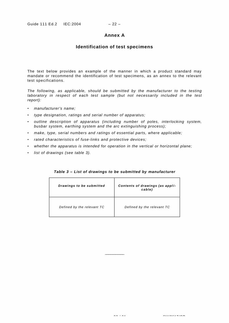
The text below provides an example of the manner in which a product standard maymandate or recommend the identification of test specimens, as an annex to the relevanttest specif ications.
The following, as applicable, should be submitted by the manufacturer to the testinglaboratory in respect of each test sample (but not necessarily included in the testreport):
• manufacturer’s name;
• type designation, ratings and serial number of apparatus;
• outline description of apparatus (including number of poles, interlocking system,busbar system, earthing system and the arc extinguishing process);
• make, type, serial numbers and ratings of essential parts, where applicable;
• rated characteristics of fuse-links and protective devices;
• whether the apparatus is intended for operation in the vertical or horizontal plane;
• l ist of drawings (see table 3).
Table 3 – List of drawings to be submitted by manufacturer
Drawings to be submitted Contents of drawings (as appl i -cable )
Defined by the relevant TC Defined by the relevant TC
___________