so*7 1 o***v
TRANSCRIPT

o*** v so* 7 1
* < *
Cfcep or*
/?> _
2&,

BLANK PAGE e
", • ^~rrr "•^VJ',^:-'!a4iriUi.^l-'^.'.".fWtaiiuj>,j)w i,. m-1 •uimaAV!".ii.i.i..-ynwm—i9WBWi

0 f M M V I C i . M M P I w Q l i Tadnie
taftev* fta*LSjprin|fcMLVi*pm?21C1 S7J0:Mki«ftc>«S2J5
Ti t *

ORNLS647 UC-7C-
CoMract No W - X O S — l J t
MOLTEM-SALT REACTUI PROGRAM
SE1RVUMRJAL PROGRESS REPORT
FOR PERIOO ENDMG FEBRUARY 21.1*75
L. E. McNcnt Piupawi Director
SEPTEMBER 1975
OAK RIOGE NATIONAL LABORATORY Oak Ridge Tennessee 37830
operated by UNION CARBIDE CORPORATION
far Hie ENERGY RESEARCH ANO DEVELOPMENT ADMINISTRATION
i/>

This report is one of a scries of periodkr reports thai describe f be progress oi the program. Other reporu i sued in this series are bsted beknv.
ORNL-2474 rVric* Ending January 31.1«*58 OftNL-2626 Period Ending October 31.1958 OPNL-2684 Period Ending January 31.1959 OIWL-2723 Period Ecaag Apri 30.1954 ORNL-2799 Period EwfcngJaty 31.1959 ORKL-2890 Pericd Endng October 31.1959 OtNL-2973 Periods Ending January 31 and April 30. I960 ORNL30K Period Ending July 31. I960 ORNL-3122 Period Endng February 28.1961 ORNL-3215 Period Fndwg August 31.1961 ORNL3282 Period Ending February 28.1962 ORNL-3369 Period Ending August 31.1962 OKNL34I9 Period Endnrg January 31.1963 ORNL-3529 Period Ending Jury 31.1963 ORNX-3626 Period Ending January 31.1964 OKNL-3708 Period Ending Jary 31.1964 ORNL-3812 Period Ending February 28.1965 OfcNL-3872 Period Ending August 31.1965 OftNL-3936 Period Ending February 28.1966 ORNL4037 Period Ending August 31.1966 ORNL4I19 Pe*»d Ending February 28.1967 ORNL4I9I Period Ending Angost 31.1967 ORNL42S4 Period Ending Febraary 29.1968 ORNL4344 Period Ending August 31.1968 ORNL4396 Period Ending February 28.1969 OKNL-4449 Period Ending August 31. 1969 ORNL-4548 Period Ending February 28. 1970 ORNL4622 Period Endtng August 31.197C ORNL-46T6 Period Ending February 28.1971 ORNL4728 Period Ending August 31.1971 ORNL-4782 Period Ending February 29. 19^2 ORNL-4832 Period Ending August 31.1972 ORNLSOII Period Ending August 31.1974

-.•.-• "K- -.•*-•--' - -•»-» .»"--'.~•*• ^^rr-^yr^^xmsj^^u^^m^llf^!^^
Contents hMroductka wm
SUMMARY ix
PARTI. MSmt DESIGN. DEVELOPMBCT.AliO SAFETY
1. DESK N VCD SYSTEMS ANALYSIS J
1.1 ~i-ji.jm Behaviorm MoheM-SakSystems 3 l.r.l U S 1 * Tritium Stoma 3 1.1 - Coobt Sail Technology Facrnty Calculationi I I
5.2 Nesfi >nk Analyses 14
1.3 rh$i Temperature Desaui IS 1.3 2 Analytical hmstjptipn of the Appfc, at * ly of Simplified Ratcfcetting and
i r**p-Fat%uir Rules m Reactor System Co nponinl Geometries IS 1.3..! t ^fasiic Analyses of MS* Piping Snfcje cted -»Internal Pressure JM) TranaeM
" .(Pperat«T Cycles 21
2. SYSTEMS *3>C0MPONr*T5 DEVELOPMENT 23
2.1 Mr.4..i «!* Steam Generator Industrial Piogrjm 23
2 J Gas-Svstarts Technology Facility 23 2.2.1 rkre»al 23 2.2.2 M * II Pump 24 2.2.3 Dcr sMwweier 25
2.3 Ctwfant-f-di Technotngy Facility 25
2.4 Forcetf-CvKectinn Loops 2° 2.4.1 Opt tXUn of MSR-FCL-2b 29 2.4.2 MS* Ft L-3and FCL-4 31
3. SAFETY STUDh.3 32 3.1 Salt Spwl / .vKknU 32
3.J I Pmesjt'al Causes 32 3.1.2 Direc. f .iwequem.es 34 3. i .3 Deferred r omrquenccs 3S
PART 2. CHEMISTRY
4. FUEL-SALT CHEM'tSl P.Y 37 4.1 Tellurium Deposition n Hasteikty N Surfaces in an MSBR 37 4.2 Exposure of NtoaMurpcal Samples to Tellurium Vapor 40

IV
4.5 Effect ui Oxygen on the I F , I F * EqMUbnwn m MoStew Ffewidc Soia(»«r> 4! 4 4 T-u- Itanium TeiraflMundeJJydrogen Euuiiitirium n Mufccn Fluoride Soiui*«i> 4 ; 4.5 Porows-Ebctrode Studies 44
5 COOLANT SALT CWMISTRY 4^ 5.1 Ckcmtttrs o f Sudram Fnjoroborjie .. . 4" 5.2 Corruaoa if Structural ANuystn FkkWMbot.net 4»>
5.2.1 TbcTModyMMictafCrtlUrm Fk*Mobuf..:e 4" 5.2.2 Metal Sonde Formaim* >«» 5.2.3 Con-mom of Nickel 58
6. DEVELOPMENT A N D EVALl'ATION OF ANALYTICAL METHODS 52 6.1 I n 4 * e Analysis o f Moke* MStJt Fuel 51 t».2 FJcwiroamhiKai Siudies o f Rum alb in Mofceu U F 4 f c F ; -ZiF.. 5 * 6 J ElectruanalytKalStudiesmMoke* SaBF 4 -Xaf 5 '
PART 3 . MATERIALS DEVELOPMENT
7. DEVELOPMENT OF MODIFIED HASTELLOY X MI 7.1 Procurement and Fabncatton of Fxprrtmenta; AKoys HI
7.1.1 Production He** 60 7.1.2 Semiproduciioa Heats 63 7.1.3 Laboratory Heals «*>
7.2 WeUabihty o f Commercial A l o y s of Modified tfasteSoy N 6 * 7.3 Stability oi Various Titanium-Modified HasteBoy N Alloys "I 7.4 Mechanical Properties of T lanium-ModiiV.! HastefloY N Alloys in the Imradrated CondiHt-n 7_; 7.5 PosuradiatH-it Mechanical Propertiesof Hv-iified HasteUoy N "*> 7.6 MKrouroclural AnalywofT-unKMi-McJiPed H u t r k N S3
7.6 I MKrosiruclurrof Aged 503and l i 4 Aloys »3 "h.2 X-Ray Analysisof PrecipMatf* *4 7.6.3 Irradiation and Creep Testing *4 7.6.4 Microslructure of Irradiated 5i !3 j'-J 114 Ailoys H5
7.7 Sak Corrosion Siudies «I0 7.7.1 Status of Thermal-Convevtirm Livp Program to 7.7.2 Fuel Salt ThermalCormcinr L«.-. Results «»l 7.7.3 Forced-Circulation Loop Resd."- *M 7.7.4 Cooianl-Sall Tcchnoloey .' • A\w Results 04 7.7.5 Static Pol Tests *M
7.8 Corrosion of Hastelloy N arc: Otiier Alloys in Steam «M
7.9 Development of a Teluriurn-Ocrivcry System for a Representative Tettunum-CorroMon Screening Test Method 102
7.10 Reactions of Tellurium wiKi -ickel at Low TeKurivm Activities 102 7.11 S'irface- and Grain-Boi,.w i»> Siudies Related to Hasielloy N Grain -Boundary Embritilemeni 104
7 11.1 Development r.f l*r>.pi.»»ed Techniques 104 7.11.2 High Temprra.urr Studies of ihe Behavior of Tellurium hi and on Fxperimenial ARoys 104

~.\2 MeniilWatum ••! RC*.IM«I I aycit ««i HasKikiy N Exposed !<> Nickd Tdlundrt 105 ~ I M MruHoejaphk.l:\jnwwlnm \'J> 7.12.2 Elewir><nMKiuprohcAnal>>rk SU5 712.3 X4ta\ DitlfKiMHt ABJI>*« iff* 7.12-4 C «Hcill»Nt> - IO»»
T . I 3 tvjaiHutnm <>t Kzaetin \ Specimem Expined in Tcfianum 10"
" 14 Opnilhw and Aiuh>r. ••! TK>n I I!'» 7.14.1 Opening tfetory .4 TeGen I I I - * 7.14.2 Data A i u l y " l«* TeGen-l 111* 7.14.3 Fului.- Irradaliom 123
7.15 Exammatitifi «l TeGen-l !23
h. F l EL PROCESSING MATERIALS DEVELOPMENT 137
•H.I Static Capsule Tests of GraphtK with Bismuth and Bbmulh-Liiimun Solutions I 3 T
X.2 Thermal Coeveciioa Loop Tests 140
K.3 TestsofOxMLiMm-Reastani Coatings •« Mild Steel Pipe 141
PART 4. FUEL PROCESSING FOR M0LTEN5ALT MtEEDER REACTORS
*». CHEMISTRY OF FLLORINATION AND F l EL RECONSTITLTION 150
10. ENGINEERING DEVELOPMENT OF PROCESS OPERATIONS 152
10.1 Instatalion of Meul Transfer Process 152
10 J Sali-Metai Contactor Development Experiments with a Mechanically Agitated Nondispening Contact** in the Sali-Btsmuih Flow-through Facility 152
10.3 Salt-Metal Contactor Development: Experiments with a Mechanically Agitated Nondrspersmg Contactor Using Water and Mercury 157 I0AI Theory 15* I0..vl Experimental Results 159 10.3.3 P»bric Determwuiion of Mass-Transfer Coefficients 160
10.4 Continuous Fluorinaior DevelopmeRt 162 10.4.1 AuiorcMstance Heating Test AHT-3 162 10.4.2 Design of Equipment fur Auloresslance Healing Test AHT-4 163
105 Fud-Reconsiiiuiwn Detdopmen;: Installation of Equipment for a Furl-Reconslilution Engineering Experiment 165
10.6 Mass-Transfer Rates in Open Bubble Columns 174 10.6.1 Experimental 176 10.6.2 Effect of Liquid Velocity on A'/,*|~ 178 10.6.3 Effect ot Viscosity on K,a\~ 178 10.6.4 Analyse of Previous Data !78 10.63 Correlation of Column Parameters 180 10.6.6 Conclusions 182
10.7 Conceptual Design ofMSBR Fuel Processing Engineering Center 182
PART 5. SALT PRODUCTION
11. PRODUCTION OF FLUORIDE-SALT MIXTURES FOR RESEARCH AND DEVELOPMENT 184
ORGANIZATION CHART 187

-.-sj£--'-*.,£>.
BLANK PAGE
.$•£!*&!• •."?•.• •'j.Tnass: WWWBWIWPBWW»J i JL-.rg^.-^.N .J-4 ,.^.H-'i^l'j,,Tt'

Introduction
The .4»Nxuvr of me Mutacu-Sak Reactor iMSRl Program ts me 4t t i l y n i of —OCJF rcaftors uof w mud (meb B M are uiMMb of tasnr and tcrtaV matcnab m «HaHc earner salts. Ike program •» an outgrowth •>• the effort hipm over 30 yean ago m the Awcrari Nuclear lYnpwJimu I ANT) Program lu make a m>dieu-*ali rcacvur power ptaM foe an-craft. A —ohm sak reactor, the Awcraft Reactor Exp< rmuul. was openicd ai Oak Rmpr National Laboratory m 1954 as pwtut the AN* Program.
The motor euai now is lu achtevc a tfaenual breeder rcictur that «di pruwaor power at km cost whde II mdijot josh couservrug and exteudmg the nation's furl resources. Farl tor am type of reactor would be : , , I T « druoheJ m a mixture of LsF and BeF : . but : ' * l .* ptuhNuum covJd be used lor startup. The icrtuc material would be TkF« dnsotced as the same salt or M a separate btauket salt of snmtar composition. The technology bone developed tor the breeder is also applicable to (Hgh-prrionmncr converter reactors.
A major program actmty through 1969 was the operatiuu of rhe Molien-Sali Reactor Experuuent I MSRE I. Tins reactor was bndl to test the types of tV A and matenab that wouM be oscd m thermal bn-cder and convener reactors: n also provided operation and mamtenance experience. The MSRE operated at lynff and produced "J Iff/ of heat. The mural fnel contained 0.9 mole T l.F«. 5^ ZrF 4. 29<* BerV and 65^ 7 U F : the uranium was about iy% "* f . The furl circnlaied through a reactor vessel and an external pump and heat exchange system. Heat produced m «V reactor was transferred to a coolant salt, and the cnotant salt was pumped through a radw A I » draipale the heat to (he atmosphere. All tins equipment was constructed of tfasteHoy N. a mcfcel-mor>'bednum-tron-chronMum alloy. The reactor contained an assembly of graphite moderator ban m direct contact with the fuel.
Design of the MSRE was started in I960, fabrication of equipmeni began hi 1962. and the reactor became critical on June I. J965. Operation at low power began in January 1966. and sustained power operation was
began m Dcuuuni 1966. One -wn mutmoed for six mondK.wjtdJtonfed on schedmen. March 196b.
C l I u u M i C f l t J u t *mf tnmB SK"4wWvwnwft fuTmt tCmfnlOnff turn? JmTSf
0VmW£T fCmCvKMS- Imn? COnwdVmSnnMi "JJnTS fluent wnmtt OnjJJJCCDVF
bad been acnarwed and rim the MSRE bad shown mat molsea^lwonde reactors can be operated at I200*F •nnVmt corrosive attach on csther die metal or ginfcu «urt» of dse vysaem: also the fuel B stable: rhe reactor compment can operate satBtactorny at these comfe-ImfnTm"*' Vu*JJJMaml uSmi Imt MafmmmmfJfl CmmmnnTw* I t l u m l unffnfBB*nl * J " * " vm»vuuiw* junjpmnmwu wvwvm una* uvwv^f^^^Bi v o m o w a w nu^num* •wwnmiw- WJ nmnuw* dmwV ™wuenTuu mnCCtTSBSHV* mnm? luTnmwOSCtlvY * B Q H n B f l M | M Cdntt On?
repaired or replaced.
The second phase of MSRE operation bean in Augnsi 196*. when a anal fadtky in the MSRE
charge from rhe fuel salt by treatment with gaseous F : . *n six days of rnjormation. 221 kg of uranium was removed from the molten salt and Inaued mto absorbers fined with sodium fluoride penets. The drrriatjmmi Hon and recovery of the utanhnn went very food.
After the furl was processed, a dsKge of * S , U was added to the original carrier salt, and m October i968 the MSRE became the world's fust reactor to operate on 13iM. The nuclear characteristics of the MSRE with die X > > U were dose to the predictions, and the reactor was quite stable. In September 1969. smal amounts of PoFj were added to the fuel to obtain wme experience with ptmoMwu in a rratan-salt reactor. The MSRE was shut down permanently Pt jember 12.1969. so that the funds supporting its operation could be used elsewhere in the research and development program.
Because of limitations on the cbenucal-processing methods avauaWe in the past. moM of our work on breeder reactors was aimed at two-flutd systems in wmch graphite tubes would be wed to separate uramurn-bearing fuel salts from ihorrunvbearing feri'k salu. However, in bte 1967 a om-fhnd breeder became
vii

W l i
teaaMe ««h lite aearlupaKat rf ptuoewes d m B K bqaal bcttaadi to nokae pruuciaaaai jad zeauxe tn< earth* Unm a a l l d m afco a * t a u ta»mi» O n '^m^tes sfcuaca riui a orf-tharf breeder buaoi ua rikf* process** caa l u w tael-aukrjiiua dkjraif«TB4K* jp-amacfcaaj dant of oat (wo-Aaat aesni »ia>> | m Saje aW papaa* semes oak as aaiarraior. dK n a flaai meter B atoar acarfr 2 scaftr-ap of dK MSRE. I k s e * * a a a » » caaxd a cfaaar • * r oapaaas of die props.:! firon dK rao-Aaai 10 * e
• M effort K aoar aaecMd to dK oae-Aaaa srswm. la the oiagKstMm' aariMuaikja Kp»n •« U K
A E C * pr.a/aaj lot FY l*»~_'_ dK JoaH CtKaMUce • « Aiuaa Eacrcy KtuiaaK-Bacw' d u i dK a«»>lie» 4J1 reactor be jr<ptj*Kd »•» d m 1 O - V D M I cuaU be ooJc aeuat its bna taamw aad dK fe**i of laaaate appr<» aroK for it. Cuasetfuearty. a riMrooaJi renew ot aK4»ra-sati tecwaotugs » J » aaacrtafcea ««» priwide a i i o n U M i lor j a jparaj j i . A ijgjafii an recall of the renew w UK preparatHwi .H ORNL-ilt i ' . T*c Drrti-'puunt SHOD <»f .U*i*r*-SJi BrecJrr R*mi.wv A sataAfaeaf « X M « was ante by the ArC ««» lenname work <ia •aokcwsail K K i t w Un bnajeetarv K3k«». m Jaaaary |47J ORNL m» Awevied ••• vewaak MSR orwdopcaeai wvrk.
la JJBVK> I**7-*, 'he AM" pr«-pj«n l.« afc4*mtj|t r«K:M orieiupBKat »i> reabUfedL A «:«*mJcubk cll.wi tatce d m laac lu» bsea ..-uacenKo' MMB a^era-baac A priipraar tiaft. twAaa; uprciaaul J •!••*! u >4 oraekipaKal faaafm B K 4 prntiabK. sni {canonc a aaaabrr t* key 4cwekpaa.ai.ii :.aaBtae> lhai bad bees rexmetrd u» .<ae: roc*** p*urA atv. A tajaJka> . jnJcnjfciae s o i k tocnata'fctf: •• oViaacd piat> l«* dK aVvrkipaiaii -•» Bto4i«n-%jis btc.-let IC* . I ««^ JMJ >btr pu^osjthn .4 URNL-5USH. frr * " "I#f !•*IXr.-if* •m-m: • 'I U 4u-n-S*ta AVkvj^r / I - .* f- TV
* • » ! ••! the Mitoa-Suii R r x h ; P I . « - M J r. n m sic«*'t«d i<> dK lAiaHAvo nceaot Ut m-nura^jti (Cik.-li>r». T I K jM.iei^n -»dao>> coaofptaji Je>«jt «IBJK> jaa mutk >m ouicrab. U K ^iKaa>t(\ ••« !»H j a j c«*i4jai «alt>. It»aia-p(«i4awi Nrfu»in». pmccd<ns •ardsuak. J M J lac 4e«eii<aaKai nf >>>ioa> j a i o«op»-acaiv T V n m aapunaai jaiflV atpcci -•€ I I K p f t u n oroeaih r> dK <K*etneaKal jaJ ataaauiraonw ••! JP aatK i lu i t> toiuMe rtw dK pnraan oroat .•« j a MSMt jarf ha» «k-^iuli: rtrxvijocir !•> fcHaium w»Ar»>ol J»a-l > * aiKreraauur cr^iiuae. alach « J B SWM « * « T \ C J m MSRt MaveiBuwie >pcw.-anen>.

Summary
r U t t . \ M&BKDESIGV DEVELOPMENT. V\D SAFETY
I . ft iqpi mi H—lj i i ,
(j>v«j:»4t> K K * i > u> t i j i i j u the >uaJv-vuu-JtxrvbuUi** .4 i n o w i and the talc at stuJi immm eater* the tieaai >y>i*u» •> nV reference i f iiai MSBR. The cjicutatium aetc bawd «m cuntM esoroates ot Material j * d >y\tem pr-fertKv and etlett* «*' douce* «i these proprcno «rrr r t j — > J. Putenliafly tanabie i i M M •^nr-jlBsp parjNefer». were saned «*et wide rangn. i» detcTEune ihew KBpnfUh>e m taartng the rate at watch intMMR ewers the >icaa sysKm. In the absence •* inlMMT. itunride M*pli»n <« rhe ^JCC graptuie. I K inluMn release t« the steam >y stent c<wid be bmried !•> * O day or leu •mk by purcmg the icioMary salt system mrth ! • - and » « M f a reduction m the hydrogen llriliwr.l permeatahly ul' ibe Oeaiu-geueratot tubes b> a factor of 100. Tuts approach < M « 4 be questionable rf ihe HF i T F ) present at hm concent ratMts m Ihe u k reacts rapsJr) with meul surfaces itt release nydroarn for dM fusion through the tmetd. Considerable intpi-.«veinrnt could he achieved, without HF rnngsne. if a htgMy eftkteni externa! gas-stnpping system could be developed to replace ihe planned stripping system, which results m arcuutmg gas bubbles. The most promtsmg approach appears to be tfce MUitiH.n <>t a chemical getter to convert the tritium lo a nonreactivc and readily removable form within ihe secondary sail.
Flux mapping and monitoring experiments were performed in conjunction with the capsule irradiation program associated with the effort to develop an improved alloy for the MSBR primary circuit. The rcsultt were wed to evaluate fission rates in the fueled capsules and to calculate fission-product inventories.
Work is being done in the ORNL High-Temperature Design Program to determine the applicability to Hasteiloy N of simplified design procedures and rules
inane devHtfed tor type 30* Uatniew. »«*l and to evaluate the severu> ut ihersni-nicheiMsg and creep-laucue damage pruNeias m the MSBR. Tk» effort. uluJi b just beguMBjR. m l eventual* be factored mto the work Vadene n» sabmtssiun .it an ASME «ode case I . * the structural sMenai ol the MSBft pirmwy wrcmt.
A cxtKcptuai deuoi MuJy •< a ><ea*> 8»e;at.ic !•• •ferale at ibe O H M IO^*-MvVte> MSBR ;ne~e^ce dexes »x> -.tWipieied b> ihe F>»:eT-lilK«ier C.«p.wa-! • • uuder >obcuntrj<.: t» OftNL. The *Kjm gener JK>C •T40I Jtosen b> Fdster-Wfser'cr t » an LthjpeJ tube-aud-iheS heal CVJURSTT »<ih an ettectne :ube kugjli ••< 140 ft. »tucb ^erafe* 3 a Moercnncai steam cycle. Fmiet-Wheeler abo completed a hterature xmey o( f l»lefliiy -to-iteaR; aimmun.
The lirsi pfease >A the vtatci runs v»as completed m the GavSysferts Tech»4i«pty Faculty. The resuituig data iodsvaieJ thai the pump perloanaace vni be vMnlaciory Jurmg sail operaiiua. altthuigh the motor horsepowe. revuireraeni wdl be higher .ban antiopaied Sunulaied tests uidicale thai the densitometer thai is to be used i.n measuring the v.^d fraction ol' the circulating water or sail may aot be capable of supplying snforma:>»n necessary to adequately evaluate the bubble-separator performance.
Operation of the Coolant-Salt Technology Facility was restarted with sodium fluon"borate, the secondar. coolant salt for ihe MSBR reference design. The revised load-orif:ce arrangement eliminated the cavitation that had occurred previously. Alter 240 hr of operation, the loop was >hui down due lo r'tigging in the off-gas lines and in the salt filler upstream of the cold trap. Plans are bang formulated and equipment assembled for the fust tritium trapping tests.
Forced-convection loop MSR-FCL-2b was operated with bF-BeF,-ThF4-UF 4 (68-:0-l 1.7-0.3 mole "Dsalt until October l"74. when the loop had accumulated
ix

X
-HMO hr of isothermal operation. The sail was then replaced with newly prepared MS8K reference-design fuel N?U | 7 M o - l . ' < U iiH>le 7 LiF-Bel; TliF 4-UF 4>. At the end of this report period, the N'^p had accumulated SOU hi of operation with the salt circulating at design conditions with a temperature difference ot 250* F. Durir's both isoiiurnvai and \T operation, the condition of the surveillance specimens indicated low corrosion rales, as expected.
Two additional forced-convec'ion-ioop facilities, designated MSR-FCL-3 and MSR-FCL-4. have been au:honvit and are in tin.- early siaga of construction. They are being fabricated of !'"• titanium modified Mastelloy N.
3. Reactor Safety
Studies examined the safety significance and potential causes of salt spills within the primary containment of an MSBR. Such spills would not iead to failure of the prinury containment, and the secondary containment would provide additional protection ;>f the public health and safety. No probable events or event sequences (other than an atbitrarily postulated piping failure as the primary event) were identified as potential causes of salt spills. Cleanup and recovery from a 'Hjsiulated salt spill would require some effort to limit the safety significance of such activities.
PART 2. CHEMISTRY
4. Fuel-Salt Chemistry
The deposition rate of tellurium on Haslelloy N surfaces in a IOOO-MW(e> MSBR was estimated. If each atom of Te (stable and radioactive) that contacts a Hastelloy N surface is assumed to react, a cumulative exposure to tliC heat-exchanger surfaces equivalent to about 52.1 mg/cm 1 would occur in 30 effective full-power years. The concentration of tellurium present after 30effectivc full-power years would be much lower: °.l I mg/cm2 of stable tellurium plus0.012 mg/cm1 >>f radioactive isotopes of tellurium.
Apparatus for the exposure of tensile test specimens to tellurium vapor was c< nstruelcd and initial tests completed. Hastclloy N specimens exhibited grain-boundary crocking after 400 hr exposure.
Extended graphite capsule equilibrations were completed at 600° C with dilute UF,-UF 4 molten fluoride solutions in contact with equal molar amounts of solid UOj and UC }. Equilibrations were also conducted with dilute CO-Ar gas mixtures, and the resulting UF.,/UF 4
ratios were measured spectropholometrically. No o.xy-carbidc pluses were formed at 600*1", and no stabilized oxygen activity was observed which could account for the apparently lower equilibrium values obtained in earlier work.
A reexamination of the hydrogen reduction of uranium tetiafluoride in mo!ten fluoride melts has been initialed. A system lias been built and is now being tested which will allow reversible equilibrium measurements to be made spectrophotometncaily at variable IIF II; ratios.
A prototype packed-bed electrode of glassy carbon spheres was tested. Results of linear-sweep voilam-metric measurements showed that the cell, the instrumentation, and the auxiliary systems functioned successfully: also, these results demonstrated the inherent sensitivity of this method of analysis.
S. Coofaat-SaH Cbematry
The compounds r U 0 B F 4 . BF,-2HjO. HBF 2 (OH) : . Na6F,OII. NajBiF»,0. and N a , B , F t O , have been prepared and characterized. Ternary solubility diagrams for the system H 3 OBF 4 HB0 2 H , 0 at 25* and 60° were established experimentally to help in the interpretation of analysis of condensates of volatile fractions above the cooisn; melt. There are indications that a compound with the empirical formula NajBjFjOj might be a stable oxygen-containing species in fluoro-boraie melts up to 550°C. Simple species such as B^Oj or B O ; ' arc not stable and are converted to species containing B F bo-'dsin molten fluoroborate.
Studies of chromium chemistry in molten NaBF 4
showed CrFj to be more stable by 6.3 kcal/mole in NajCrF 6 than in NajCrjFi*: this explains why NajCrF* rather than Na 5 C r 3 F | 4 precipilates from the NaBF 4-NaF coolant. Equilibratio . of Hastelloy ft and Inconel 600 with NaBF4-NaF eutectic for up to 72 days at 640°C caused minor increases in the surface boron content for rlastelloy N and significant increases for Inconcl 600. Evidence of reaction of CrF, with nickel was obtained. Evaluation of the data for the react* n NaF(c) • NiF 2(c) = NaNiF,(c) showed that the enthalpy change at 25'C was vir'ually zero.
6. Development and Evaluation of Analytical Methods
Voitammctric techniques arc used to measure I **/{j}* r a t j ( ( $ a r u i ( ( t observe corrosion-product ions in MSBR fuel in all corrosion test loops that are in current operation. Ratios are presented graphically for the initial period of operation of forced-convection loop

X I
FCL-_h. During this report period the redox condition o( uranium in an experimental fuel solvent. LiF-BeFj-ThF 4 168-20-i 2 mole '»). was adjusted by additions i>f beryllium metal and nickel fluoride. Effects of additions of reduciant and oxidant are clearly distinguishable on the plots, and stoichiometric reduction by beryllium of tetravalent uranium to the trivalent state was demonstrated- After additions of both reductants and oxidants, a tendency for the Lr**/U : H ratio to return to the value prior to the addition was observed during the following few days of fuel circulation. Attempts to make quantitative interpretations of chromi' m waves are in prog;e\s. Similar measurements are now being made of reference fuel in this loop and in two lh?rmal-conveciion loops.
Continued studies of the voltammetric measurement of BiFj in LiF-BeF2-ZrF4 were made in the presence of NiFj , an ar .tcipated interference. Limits of detection were about 10 ppm by direct scan voltammetry but were extended to a level estimated to be less than 25 ppb by stripping techniques. Preparations are being made to perform similar studies in reference fuel solvent.
An anodic wave, discovered at a gold electrode in NaBF4-NaF eutectic. has been shown to be directly proportional to NaBFjOH concentration. The wave is complicated by catalytic regeneration of the reactant. However, when measured under constant voltammetric conditions, its height is proportional to the concentration of BFjOH" as determined by infrared measurements.
PART 3. MATERIALS DEVELOPMENT
7. Development of Modified HasteOoyN
Scale-up of the I'H Ti-modified Hastdloy N was advanced by melting two large commercial melts weighing 8.00C and 10.000 lb. Fabrication of the first heat (10,000 lb) was difficult because of its narrow working temperature range. The working temperature range was much broader for the second heat; so fabrication was easier. Several products were obtained, and other products, including tubing, are being fabricated. Small commercial melts were obtained which contained 2% Ti and small additions of rare earths. These alloys had good weldability, and their mechanical properties in the unirradiated and irradiated conditions were superior to those of standard Hastelloy N.
Two thermal-convection loops and one forced-circulation loop, FCL-2b, circulating the fuel salt are in operation. The operating times are short, but the Inconel 601 thermal-convection loop exhibited rather high corrosion rates. The other two systems are
constructed of standard rbsteiloy N and exhibited lower corrosion rates. Hastelloy N specimens exposed in the stressed and unstressed conditions to steam in the Bull Run Steam Plant fail to show any adverse effects of the .team.
Considerable effort was spent to develop a screening test for evaluating the compatibility of nrctab with tellurium. Several methods of delivering tellurium to metal surfaces at a controlled rate are being evaluated. Several analytical techniques were developed or improved for studying the specimens reacted in these tests. Nickel foil was exposed to a partial pressure of teliurium too low to form a stable teliuride. but it was embrittled.
The first fueled irradiation experiment was fabricated and irradiated successfully. The three fuel pins from this experiment (TeCen-li were partiaiiy examined. Metallographic examination of strained segments of the fuel pins showed that the standard Haslelloy N cracked profusely, that Inconel 601 was almost totally resistant to cracking, and that type 304 stainless steel formed very shallow cracks. These three cracking responses are essentially those predicted on the base of our laboratory experiments.
8. Fuel Pi w i iiiwg Materials Development
Experiments were continued to determine the compatibility of graphite with lithium and bismuth-lithium solutions. The solubility of carbon wa found to increase with increasing lithium content in bismuth-lithium solutions at 650°C. The rate of thermal-gradient mass transfer of graphite is being determined in a molybdenum loop circulating Bi-2.5% Li at 700°C maximum temperature with a temperature differential of I00°C.
No evidence of intercalation compounds was found in graphite exposed to Bi-Li-K and Bi-Li-Cs at 450 or 650°C. However, there was mass transfer of molybdenum to graphite in three-component lest systems at 650°C.
Lithium was found to react with graphite at both 250 and 650°C. No evidence of intercalation compounds between graphite and lithium was found at either temperature, but at o50°C, the graphite was converted toLijCj.
Coatings of Ni-AI and Ni-Cr-AI were applied to a plain carbon steel to determine their effectiveness in preventing air oxidation of the base metal. Samples were heated at 700°C for 401 hr and it 8I5°C for 520 hr in air and thermally cycled 16 times to lower temperatures. The Ni-Cr-AI coating (Metco P-443-10) was

X ! l
superior to the Ni-AI coating (Metco M-40S-I0) under these conditions and appeared to give adequate protection when applied properly.
PART 4. FUEL PROCESSING FOR MOLTEM5ALT BREEDER REACTORS
9. Owwiitij of nunririrtwi mi Tml ftrrortiluti—
The rate of reduction of UFj dissolved in fuel salt by hydrogen gas followed zero-order kinetics at 550°C. The rate constant was independent o( uranium concentration, hydrogen flow rate, and hydrogen partial pressure. Hydrogen utilization in these tests was <l '? . The apparent reaction rate was increased by approximately two orders of magnitude and hydrogen utilization increased to near stoichiometric by the addition of platinum catalysts to the melt. Even trace quantities of platinum that combined with the gold reaction vessel liner were adequate to effect the same increase; thus practical application of this catalytic effect of platinum can be readily attained in the fuel reconsiituiion step.
10. Engineering Development of Processing Operations
Engineerirg experiments to study the steps in the metal-transfer process for removing rare-earth fission products from MSBR fuel salt are to be continued in new process vessels which duplicate those used in a previous experiment. MTE-3. Installation and preoperational testing of the new equipment for the experiment, designated MTE-3B. have been completed. The addition of the several salt and bisnulh phav- to the salt-bismuth contactor and stripper vessels is under way. One to two months will be needed to complete these additions before experiments can begin to measure the transfer rates for removal of rare earths from the fuel carrier salt.
The seventh, eighth, and ninth tracer runs (TSMC-7, -8. and -°) were completed in the mild steel contactor installed in the salt-bismuth flow-through facility in Building 3592. Run TSMC-7 was made at a low agitator speed (68 rpm) to help define the effect of agitator speed on the salt-phase mass-transfer coefficient under conditions where salt is not dispersed into the bismuth. The mass-transfer coefficient for this run was 0.0057 ± 0.0012 cm/sec. which is b$"r »f the value predicted by the Lewis correlation. Run TSMC-° was made at a high agitator speed (244 rpm Mo determine the mass-transfer coefficient under conditions where salt is dispersed into the bismuth and to determine if large amounts of bismuth and salt are entrained in the other phase. The
mast-transfer coefficient was 0.121 t 0.1 OK cm/sec. vmkh is 178% of the value predicted by the Lewis correlation. The data suggest that when the phases art. MM dispersed the effect of agitator speed on the mass-transfer coefficient is less than that predicted by the Lewis correlation.
Mass-transfer rates between water and mercury have been measured in a mechanically agiia'>-d contactor using the reaction
r V l U j O l • Zn{Hg| - Zn 2*lHjO| • Pb(Hg| .
Data from a series of five experiments have been reanalyzed using a model that wrs based on the assumptions that the reaction is instantaneous and irreversible and occurs entirely at the water-mercury interface: thb reanalysb is to determine if an apparent change in mass-transfer coefficient during the execution of a run was due to the controlling resistance to mass transfer changing from one phase to the other. Several inconsistencies were found between the model and the experimental data. Several runs were made in the water-mercury contactor at an elevated temperature Cv<40*C) to test the validity of the assumption that the interfacial reaction is instantaneous. Results from these tests were inconclusive.
Investiption was initiated to determine if polar-ography is a viable alternative method for measuring mass-transfer rates in a stirred interface contactor using mercury and an aqueous electrolyte solution. Several electrolyte solutions were investigated, but none was found to be entirely inert to mercury. Information found in the literature suggested that the Fe2*-Fe** redox couple (using iron complexed with oxalate ions) may be suitable as an electrolyte fix our application. Further tests will be performed to determine whether the iron oxalate electrolyte will produce suitable polarograms.
Additional runs were made in a simulated fluorinalor in which the vessel wall is protected by a fro/en-salt film and fission-product heating is simulated by auto-rcsistance healing. MSBR fuel salt was used in these tests. Successful operation was not achieved with the electrode in a side arm (necessary to avoid corrosion when using fluorine). However several apparently successful runs were made with the electroce at the lop of the vertical test section. Successful operation with the electrode in the side arm may be demonstrated in the next experiment, now being installed, which will employ a circulating salt stream.
Measurements of mass-transfer rales in open bubble columns during CO : absorption in water were con-

U l l
linued. Results were extended to include the efforts of liquid viscosity as well as effects of gas- and bquid-flow rates -in nuss-transier rates. Further improvements wer? made in the experimental technique and all previous data were critically reevaluated. The new data were combined with the most reliable da'a from earlier work to produce cm relations for estimating bqutd-Tdm mass-transfer coefficients.
Installation of the fuel-reconstitution engineering experiment in Building 7503 is expected to be completed in early April 1975. Details of the equipment for this experiment are descrmed-
A floor plan for the MSBK Fuel-Processing Engineering Center has been developed, reviewed, and approved. The conceptual design of the building is under way and an Engineering Job Plan has been developed for the design.
PARTS. SALT PRODUCTION
II . PinmKttmnf F h m r i d e « t M n f e s
Activities during the report period fall in three categories: (I ) salt production, (2> facility and equipment modification, and (3) peripheral areas that include preparation of transfer vessels, assistance to others in equipment clean-up. and reactivation of liquid-waste handling facilities and procedures.
Salt production for the period, totaling 358 kg :n three different compositions, was delivered in 22 different containers and required a total of 30 salt transfers- Most of lite salt was produced in an 8-in.-diam purification vessel and had acceptable purity leveb.
A significant effort was devoted to installing of a new 12-in-diam purification reactor and a new melt-down vessel in the large production facility, to upgrading the associated electrical power system, and to placing the remainder of the facility in operating condition. Load-in}, of the first batch of salt to t!ie iarge production system was in progress at the end of the report period.

Part 1. MSBR Design, Development, and Safety J. R. Engel
The composite objectives of this program are to evolve a conceptual design for an MSBR with adequately demonstrated performance, safety, and evo-nomic characteristics that will make it attractive for commercial power generation and to develop the associated reactor and safety technology required for the detailed design, construction, and operation of such a system. Since it is likely that commercial systems will be preceded by one or more intermediate-vale test and demonstration reactors, these objectives include the conceptual design and technology development associated with the intermediate systems. In addition, molten-salt reactors may be attractive for applications other than electricity generation in large central stations powered by breeding cores, so this program also includes the examination of alternate MSR concepts.
A conceptual breeder design has been prepared and described' by ORNL and an independent design study was performed2 by an industrial group under sub contract to ORNL. In addition, an initial conceptual design has been developed.1 under subcontract, for a molten-sait-heated steam generator to produce supercritical steam for an MSBR plant. The design of the remainder of the plant, including the secondary salt systems and the steam system, is incomplete: therefore, the safety, performance, and economic analyses cannot be precisely made. The industrial study and other internal reviews have shown that several aspects of the basic conceptual design of the primary system could be improved to enhance its overall attractiveness.
1. Molten-Salt Reactor Program Staff. Conceptual Design Study of a Single-Fluid Molten-Sail Breeder Reactor. ORNL-4541 (June 1971 >.
2. F.basco Services Incorporated. lOOO-MW(e) Molten-Salt Breeder Reactor Conceptual Design Study Final Report Tank I (February 1972;.
J. Foster Wheeler Corporation. Task I Final Report Design Studies of Steam Oenerators for Molten-Salt Reactor. Report ND/74/66 (Dec. 16. I971>.
The current emphasis in the MSR Program is on the development of the basic system technology, and no specific design work is now in progress. Design-related studies are being performed as required to support technology development, particularly with respect to safety analyses, tritium management, high-temperature design methods, and evaluation of basic design alternatives. As the basic technology becomes more firmly established, the design effort will be expanded to provide a better basis for the required performance and safety analyses.
The design work on MSBRs has indicated several areas in which reactor technology must be developed to properly make use of the inherent feat ires of these systems. Components and subsystems will be developed and operated on various scales up to full size to contrioute to this technology. Currently two engineering-scale and some smaller scale development efforts are being pursued. A Gas-Systems Technology Facility is being constructed to permit studies of helium-bubble injection and stripping, on a scale representative of a test reactor, by methods that are •expected to be amicable to larger systems. This facility will also be used to stutiy other engineering phenomeni. for example, xenon a>id tritium behavior and heat transport, in a system containing MSBR fuel salt. A Coolant-Salt Technology Facility is being reactivated to permit studies on a similar scale with the sodium fuoroborate coolant salt. The initial studies will be aimed at developing a better understanding of tritium behavior and management, and the behavior of corrosion products in sodium fluoroborate. This facility may also be used to study, on a small scale, the generation of steam with molten salt. These loops will also contribute to a better understanding of the technology of molten-salt pumps.
A small forced-circulation loop is being operated and two others are under construction to support the development of a structural alloy for the MSR primary
1

r 11 "^VJSMfelt'JgSE .'*S3S**5^^«W(f^3gi^5gBSKH
BLANK PAGE u
i
«^v:i^-^i-w*"m^J-^w>-J'-i ,w'!'' l !*^^

cavort. These facilities penai: die exposure of candidate structural materials to MSBft salts at maximum desam temperature ( I300*F» and temperature Jiitaeu-lu l C50*F ) with reafoik sah flow vciuattes m dKuucai etrrironmeats dot cam b» readly maniputaKtf- Effects of specific IBNOU products <e.$.. tefluniaa I ami sail redox conditions J*-*,- l"** l , J * ratio) can be stndied under conditions diat snuatate many features of the reactor system. In addiuoa. smaii capnues of stationary far! salt and aftov test spedmeis are irradiated to sludy
sepcreu!y the effects ot ;o.-tor-$raeratr«! ttsmm JNO-dncts and radiation on rcivnals.
Because die fuel in an "MiR is omitea and rt orcnUted tbronfh the phoney citcnit. safety v-uatidf rations tor das concept differ front those of suad-fuekd systems-Stud*» are bean; made in order o identify and describe the postulated events and event sequences that are important to M S M safety. These events wal be evaluated ia greater dttad as the system conceptual desaens evolve.

•»
I. Design and Systems Analysis JREftget
I.I TMTOJM BEHAVIOR M MOLTENSALT SYSTEMS
G. T. Mays
I . I . I MSB* Tritium Studies
Revisions of the computer program for calcinating the steady-slate distribution and transport of tritium in an MSBR1 were completed. The program has been used to investigaic tritium behavior in the 1000-MWlc) reference design MSBR. in which a tritium production rate of 2420 Ci/day is expected.1 Reference values for some of the parameters in ihe computer program have not been confirmed experimentally, so the potential effects of these parameters upon tritium transport were examined for a number of combinations of operating conditions. Various hypothetical methods of limiimg tritium transport to the steam system to within the design objective of 2 Ci/day were examined also. If the tritium entering the steam system at this rate were routinely released in the condenser cooling-water effluent (~560j000 gpm for once-through cooling), the tritium concentration would be a factor of 4600 below .he limits of 10 CFR 20 and a factor of 8 below the guideline of the proposed Appendix I of 10 CFR 50 for light-water reactors.
1.1.1.1 Background and basis for computer calculations. Tritium distribution is calculated for the reference design MSBR plant having a primary sail system, a secondary salt system, and a steam system consisting of a steam generator, steam reheater. and superheater. The fluid in each of these three systems is assumed to be well mixed and to contain uniform bulk c mcetitrations of all constituents under steady-slate conditions. In addition, hydrogen isotopic exchange reactions are assumed to proceed rapidly in all the chemical forms considered, so that isotonic equilibrium exists throughout each system.
The mathematical model of the primary system provides for production of tritium in the fuel salt, mass transfer of elemental hydrogen1 to and permeation through the metal walls of the reactor vessel and piping
1. R. B. Brigs and C. W. Nestor. A Method far Cslcuktinf the Steady Slate Distribution of Tritium in a Molten Soil Breeder Kejclor Plant. ORN L-TM-4804 I April 1975 t.
2. Oak Ridee National Laboratory, Conceptual Design oft Single Fluid Molten-Salt Breeder Reactor. ORNI.-454I Hunt 1971).
into the primary containment atmosphere, removal of gaseous H , and HF by purging the salt with reulaung helium gas bubbles4, sorption of gaseous H i ami HF ua graphite, and transfer of elemental forms to ami through the metal walsof the primary beat t Albany i tubes into the secondary salt system. The equations for ihe secondary system treat the transfer of Hfinrntal forms through the piping into the eel atmosphere, mrgmg by circulating helium gas bubbles, and transfer thtongh the tubing wans of the steam generator, superheater, and reheater into the steam system. The introduction of chemical agents into the primary and secondary salt systems for removal of tritium is also provided for.
The steam system and the cetb around the reactor primary and secondary systems are considered lo be sinks for mnum. Disposition of the tritium that reaches these locations b not treated explicitly in ihe model, but the tritium probably would appear in liquid wastes.
Some of the processes identified above are not drs-c-jssed explicitly in ihe description of die reference design MSBR. they were included in the computational model to provide greater flexibility in considering potential approaches for achieving the design objective for tritium release. These processes are the circulating-bubble purge of the secondary salt, sorption of gaseous forms of hydrogen in ihe secondary system, sad the addition of chemical agents to facilitate removal of tritium from ihe primary and secondary systems. The results given in the remaind>r of ihb section include - H » -sideraiion of all these processes except the sorption process in the secondary sail. I No simple procedure could be visualized lor implementing the sorption process in a reactor system. I
Hydrogen is presumed to exist in the fuel salt in an elemental form ( H ; I and a chemically combined form
3. Throughout Ibis «ction. H *iB be con*cmenf lo use ibe term* hydr<uxn and hydrogen fluoride and rbe symbuh H. and HI when reference B nude lo ibe Uwmiul mnits. mdcprnd cm of hydrogen notopK composition, t-ur specific lefarcnu lo elemental inlium and tritium fluondc. rbe symbols wed are *H . leven though ii probably ocean a* ibe nm«d molecule ' H ' HI and ' H I . lor specific reference to ihe more abundant hydrocm isotope, the terms prnthwn and protmm fluoride and the syrr. bois' H. and ' HI- arc used.
'.. The nominal drum function of the orculalmc fa* nubbles is lo provide smppmc of noMr-gaa fhnwn products lo limil xenon poisoning.
4
lHF» HI rebate a w M B that depend OK she rtdox potential of rhe salt ul" the UF« l : F , n u t . thai » LT« * % H; *TF , • HF. la « M K M . the I K I I ) ratio Jewimiatj, largely the corrussou potentai m the primary system became ul reactions of the type 2UF4 • M*~2UF, • MF 2 . ll the corrosion effects resuma* from a UF« l-F, ratio greater than the value of 100 n i M t i m the reference design ate found iw be tolerable, a large; fractum of the tntnuu would be present as t in—i tnsonde. Under some coairtjuas. intaaw fluoride aught react with the metal wait of the reactor system to produce elemental trrtiam. which could the* M a t through the wafts, that K.
2 W » M * ~ M F . + H z
However, fur these cakatatioas rf was assumed that hydrogen fluoride, at low conceatrafioas aad tolerable salt redox potentials, would react sufficiently slowly with the metal wafc that the coatrumiiou of 'HF to inimm transport through the wafc could be neglected. Howcver. the rate at which HF reacts with the metal wal! ander these conditioas rs aot known, aad neglecting this effect coaU caasc the calculations to uader-estimate tntnan release m circumstances where mach uf the tritium is present as tntnan fluoride.
In the primary circait. hydrogen fluoride wal be produced by the react**-:
UF 4 • ' ^ H j - U F , »HF.
lor which the equilibrium quotMnt may be written:
JHUF,) /1HF> _ „ jnuF4i*|f iH,n • / » " * •
where
X x concentration.
P= partial pressure.
The reference value used for (be equwmrwm quotient. M= 112 X 10 • W ' ^ a d n t m e d t c l e d b y tlcdala of Long and Hartkeusmp*. Although the value is bawd no experimental measurements, there is some uncer-tainiy about iis mjgmiade. A decrease in the value of the equilibrium quotient would have the same effect with respect to tniNnn behavior as decreasing the
5 t;. Uaj am 1.1, fcan^. I V Jmfwj ofltmmn I M ^ a W a W . nff 99. Sttttwty *W Mfpftftt H l u t f M f aWNMDN. OKNL-TM-ms. Part II (Noaaaatr l***i.
IRVUFj rata* (with a erven eqmHiiuuu quotient vahstl wade aa mcrease m the value would have the opposite effect
The secondary system of aa MSMt would aot aoranhV coal-— consiuuents that are capable oi' oxi-Jraaj, hydrogen to hydmgen flaunde to hant the avari-abthtv of hydrogen for datfassoa through the metal wafc- Therefore, the model provide* for the addition of proiiani Awr-isie ot other coaaaaaads coataimag pro-taua to the Hvautory system. It is jjjumid that the tnfana wal exchange with the pmiiaui ia the added coaavouad and thai the compound can then be re-
deschpdon of trithaa behavior. These in dad t The transport of H, and HF from nte fuel salt to the graphite moderator in the reactor cove. nV traasport of H 2 from sail to various metal surfaces in both rhe primary and retoadary systems, and rhe traasport of H x from the steam system to mam gruenttit surfaces. In a l cases, these processes arc described by coavcationai ari t 1
transfer relations of the form:
£«*KV-C 5 l
where
— = transport rale per unit of mterfacial area. A alonavlsrc cm2)
h - mass-transfer coefficient, cm/sec. aad
Cg. Cs = coaccntraiions in rhe bulk fluid and at the interfaces atoms per cubic ceniimeler of salt.
The mterfacial areas are appropriate for the reference design M S M . and the mass-transfer coefficients were cakafaled from hea'-transfer mass-transfer analogies for the fluids in question. The reference "alues for areas and mass-transfer coefficients are hsieJ {Table I.I I. these values were nut varied in the slvdies reported here.
la addition to the mam transfer processes that were treated explicitly, the effects of anas transfer of hydrogen and HF lo the circuialiag purge gates were described, also. fteluKmary catenations indicated that the transfer of hydrogen and HF wiN he limited by thr saturation concentrations of the stripped fates in the bubbtrs. rather than by maa> transfer to the bubbles, so thai eqmhbraiion between the gas and liquid phases could be assumed. As a consequence, effective H 2 and

-s«*m»6..-' -*-^ >j**'3«*^5i*S***:*:»fci .IHJJLIWWI
M m umtht la t t rbcal MBtBTSaV Tnafcf
turn T r a i n
I D : coefficient <aa/scc>
a a <oa*>
H , F a d s * Prianry loo* hot-Ice M l . * X 10 * 6.0 X 10 s
H , M a d h w r ' loo* oohMaj pi fc.OX 10 ' S.0 X 10 s
H , F a d d l ltcacl.it t e n d aa* are* te+fccMcidMajriJ ».0X 10"* 3.5 X 10*
H , F a d s * n u u i y b w a m exekfl BUJR takes I.»XIO-" 4.» X I 0 T
H..HF F a d s * Cjcrpaatate 3 .0X10"» 5.2 X I 0 T
H, Codaatsdt jccoaaaiy loop bot-kg 1 7 . 4 X 1 0 " * I . I X I 0 T
H, C M M s f t SrcMfaiykMpoohHt i laieiae 3 . 4 X I 0 " 1 M X 10* H , CootaMsd: S e ^ y l ^ b a t c a ,
9.1 X 10 -* 4 . * X 10* H, C o a f a M d l S « o - * r , l o c p « c - «
4.3 X IO-» 3.1 X 10* H , C « h M d l 9CVJ)aVaT^aWj I W P ^•ayOaW a m M a s 4.7 X 10 "* 2.7 X 10* H, C a t t a N d i dnSHPtafaaWj ROTPp P^v^ESlV i Macs 4.0 X 10"* U K 10* H..HF CodaMsrft Surfaces of saivcr S.0X 10'* 0 H , Wslcr S a n n svsasai steam atnetatov
M h o 5.t 3.1 X 10 ' H, Wain T n — IJ in — lapnam Intake* 12.0 2.7 X 10* H, Wattr S t t a » s n k » f r f t * a * r 1 30.0 l . t X 10*
HF removal efficiencies were calculated for the bypass streams, from which bubbles are stripped, as a function of purge gas throughput rate for application to the sail bypass (low rates and the nominal salt concentrations. For the reference gas purge rates of 10 and 20 scftn for the fuel and coolant systems, respectively, and gas stripping from 10% of the salt flow, the Hi and HF rem aval efficiencies are:
For Fad a h Coobat M H H» 50% I t * HF 1.7% 0 . 1 * *
At metal surfaces, the dauociation and diffusion of hydrogen through the metal is described by:
A 4-Aiy'1 v 2 >.
p • permeability corffjeicm. ( a t o m * H ^ a m > i . p permeNHHty o m n s m n * i m c } { a ^ U m m m i f
ff,tom pwial preawre of hydrogen at inner and
The premcaMiry cofftlchmu for hydrogen diffusion through IhHdloy N am baaed on work by Webb*, later
measurements by Strehlow and Savage7-* are in reasonable agreement with these values. Webb's relation:
l? s aexp
where \ RT '
(atoms HXmm)
(secXcm'Katm1'2)
0« 13,800 cal/moie.
/J=l98cal /mok 0 K,
T* temperature. *K,
was used for the reference values in the computer program. These values apply to bare metal in the primary and secondary system piping in aD of the calculations: However, these coefficients couid be lower for the steam-system components due to the formation of oxide films on the steam side. Reductions in the nominal permeability coefficients by factor* ranging from 10 to 1000 might be expected, which would decrease tritium transport to the steam system. Oxide
a. •• w. werA\ nnttttton of HydNggn NAA-M-I0M2 (Jet* 25. IMS).
7. R. A. tuiahu M J H . C leva*. M R Ihajww Stmt-mm. Mar- i h > M 9 . 1 9 7 2 , OBNUOTU, an. 54-55.
t. R. A. twmtow aai M. C Savaar. JflR /Hunan L Htp.Amt.il. '977. ORNUM32.ee. 39-42."

6
films may also cause the transport process to vary with partial pressure raised to a power greater than %. with an upper limit of I . The permeability coefficients may be varied in the computational model, but no provision is made for changing the exponent on the pressure terms from %. Use of the % power relationship would tend to overestimate the rate of tritium transport through the metal watts if the uctual process were proportional to the pressure to a po»ci greater than %. The calculations would not underestimate die transport unless the partial pressure of hydrogen exceeded the reference pressure for the permeability coefficient, which is usually I aim.
Partial pressures of dissolved gases are used to describe the sorption processes, as well as the penrtea-tion of metals by hydrogen. Therefore, solubilities of Hx and HF in both the furl and coolant salt arc required- The partial pressure. P. of a dissolved gas is related to its concentration at a given temperature by:
P=KC.
where
K - Henry's law constant' for the solubility of gas in salt.atm/(atom H/cm 1 salt).
C = concentration in the salt, atoms/win*.
The solubility coefficient or Henry's law constant for H? in the fuel sail is described by an empirical relationship1 * based on experimental data, from which estimates1' of H 2 solubility in sodium fluoroboratc were also derived. This relation probably yields reasonably accurate values for the fuel salt, but the values for sodium fluoroborate are less certain. Experimental data 1 2 were used to estimate the solubiKty coefficient of HF in fuel salt and to infer a coefficient for coolant salt. Reference values of the solubility coefficients for H* and HF in various pans of the system are listed (Table 1.2). Owing to the greater solubility in salts for HF than for H , . significant variations in the solubility coefficients for HF would be expected to have a greater effect on the calculated
9. 11K reciprocal of diet quantity may abo be referrad to as a Henry's Law conataat-
10. Oak RMJC National Laboratory, internal corrapundene*. MSR-70-79.
11. Oak Ran* National Laboratory, internal niwajuna'iait. A. t. IMiMMfcae, £Manffr of Trtttmm JMUMrr *» Sodium RHofowoMt, latter to H. A. McCMn, How. I l f 1970.
12. Oak RMja National Laboratory. internal curr—»uno»»n, MSft-70-U.
tritium behavior than comparable variations in H ;
solubility. Evidence from the MSRE and other experimental
work'* 'ndicaie that tritium will be sorbed on graphite, but sorption of tritium fluoride on graphite is questionable, owm; largely to the low permeability of the graphite w i h r-spect to gases. Since the calculations indicate that tritium fluoride sorption on graphite would be a significantly more important tritium-removal mechanism than sorption of elemental tritium on graphite, conditions neglecting sorption on graphite were also examined. To permit consideration of the core graphite as either a highly efficient sorber for Hi and for HF or as a nonsorber. an expression was developed to describe the sorption process as a mass-transfer rate. In developing this expression it was assumed that the concentration of gas sorbed (either H , or HF. either tritialed or not) on the surface of the sorber is proportional to the square root of the tritium partial pressure in the gas phase at the sorber surface and that the sorber surface could be replaced at an arbitrarily specified r^ic. The latter assumption permits use of the same expression to describe the continuous addition and removal of a sorber in the secondary salt system. The resultant expression is:
A
where
B - sorption coefficient. atoms/(cm2 aim' I2).
rV = sorber replacement rate, fraction/sec.
#*= gas partial pressure, atm.
To eliminate sorption as a mechanism, the sorber surface area. A, a set equal to zero, and to describe a highly effective sorber, that is, an infinite sink, the surface replacement rate, W, may be made arbitrarily large ( e j . I sec' 1 ) . A sorption coefficient for Hj (and HF) was calculated from the observation that, at 600°C and 10" ' aim, hydrogen is sorbed on graphite to the extent of about 0.01 of a monolayer. This value, coupled with the observation that tritium in the MSRE was sorbed to a depth of about 1.5 mm on graphite with a density of I J* g/cm* and a surface area of ""I m a /g , leads to a sorption coefficient of 3 X JO 2 1
atoms/(cm2 a i m 1 ' 2 ) , in terms of the superficial graphite surface area. However, since only extreme cases were
13. R. A. SuvMow and H. E. Robertson, MM f h » w fcmtaMK Annr Hep Feb. 2*. 191$. ORNL-5011, pp. 30-33.

7
(asatftaan Won' afe) r»
H, HF H, H, H, H, H, H, H, HF H, H, H,
CootaM sit Sarins j f sorter CoohMsrit SMtacn of Salter Steal
Steam*
1.2 X 10-' 973 W X U " S3S
u x w " 9 M 1.5 X 1 0 " 9 M I . 4 X I 0 " 1 923 I J X I O " •23 3.4 X I O ' " 094 Si) X 1 0 - • 723 4 J B X 1 0 - , » 109 4.5 X I O " 703 3.5 X I O " OS* 4.0 X I O - " •10 4.4 X I O " " 773 1.1 X 1 0 " 773 4 J X 1 0 ' " MO 5.1 X 1 0 - " 775 4.* X 1 0 " 714
considered in the calculations, the specific value of the sorption coefficient is unimportant for the results obtained to date.
Calculations have been made to estimate the behavior and distribution of tritium in a l000-MW(e) MSBR with parameter values and operating conditions associated with the reference design and for a number of other assumed parameter values and conditions. The primary purpose was to determine if possible combinations could be idenliricd which would limit the rale of tritium transport to the steam system to 2 G/day or less. The reference design conditions include sorption of H , and HF by the core graphite, a U F 4 / U F , ratio of 10*, and steam-system tjbe permeabilities lo hydrogen that are appropriate for dean metal. Other parameter variations and operating conditions examined thus far consist in the following:
1. deletion of sorption of H j and HF by the core graphite,
2. U F 4 / U F , ratio, 3. permeabihly of the steam-system tubes lo hydrogen, 4. rale of addition of hydrogen lo the primary and/or
secondary system, 5. rale of addition of hydrogen fluoride lo the second
ary system. 6. sail bypass flow rales and purge-gas flow rales in the
primary and secondary systems, 7. an alternate side-stream contacting process for the
primary and/or secondary system, such a» a spray
tower or packed column, with no limitation on the purge-gas flow rate through the contactor and an assumed removal efficiency of 99% for H j and H F m the bypass salt stream (10% of main flow),
8. rale of hydrogen back-diffusion from the steam system as a consequence of hydrogen concentrations in the steam system greater than the reference values, due either to deliberate additions or to corrosion effects.
9. rale of addition (and remu'al) of a hydrogen-bearing chemical species or getter to the secondary system to establish the circulating .-oncentration necessary to limit tritium transport to the steam system to 2 G/day or less, for a predetermined rate of processing the secondary coolant.
In addition to the calculation of the effects on tritium distribution of each of the above parameters and operating conditions singly, with the others held at their reference values, calculations were also made to show 'he effects of variations in combination with reduced steam-lube permeabilities, higher U F 4 / U F j ratios, and no sorption of HF or H j on core graphite, because of the potentially large effects of these three parameters.
Hog c M u W s m Under reference conditions (no special measures taken to limil tritium transport, sorption of HF and H j by graphite included, a U F 4 / U F , ratio of 10*, and steam-system lube permeabilities that correspond to dean metal), - 3 0 2% (731 G/day) of the 2420 G/day of tritium produced transfers lo the steam

s
syssta. When sorption by graphite is assumed not to occur, about SS.9% of the tritimn produced (I42S CW'day > transfers to the steam system. These values air to be compared with the design objective for tritium transport to the steam system ot 2 G/day (about 0.1% of the production rate).
The effect of increasing the U F 4 / U F , ratio for a range of steam-system tube permeabilities both with and without sorption of hydrogen and HF on graphite is shown iRg- I . I ) . It unlimited sorption on core
75-«SW
«r -
5 -
r o a 5
«>
l i 2
Id
«f
Z n - 2-i - S.i
1 — 1 - - ! EFE ENM
1II HTM CM VITHOU NEMCE EAfJUT no^o
Mil tAMTESC rotAmrr STEAM TV
NF1 E S • E
1 I I I ! noN 0NPTI0N +
" " " ^ ^ T^
E^I : : : : : ll5v. ' ^ s
Vi N ' ^
fltl"""*"*! - ^ ***ZJ?.'.
-lit. \
TITI 5 «0* 2
\)F4/UF3 RATIO
Fh> I . I . Effect* of UF,/UF, »atk> on tritium nam fystwu far vanou* n i n m w suipuuu of
tramftr to
graphite is ammatd to occur, the triiium transfer rale to the steam system w2l be 2 Ci/day or less for UF«/UF, ratios of 7 X I O J or higher, even with dean steam tubes. Under these condiitom. a large fraction of the tritium is present as uithMi fluoride, and sorption of tritium fluoride by graphite would become the primary mechanism for removal of tritium from the fuel salt. However, if graphite sorption is assumed not to occur, unacceptabty large quantities of tritium would enter the steam system even with the steam-tube permeability value reduced fiom the dean-metal value by a factor of 1000 and a UF«/UF, ratio of 10*. Under these latter conditions the primary system purge-gas stream would remove 87% of the tritium, but 34 Ci of triiium would still reach the steam system. Thus, the rate of triiium transport to the steam system o n be limited to 2 Ci/day in the absence of speckl removal processes only if sorption of both hydrogen and HF on graphite is assumed.
The effects of reduced permeability of the steam tubes on the rate at which tritium transfers to the steam system with a U F 4 / U F j ratio of 100 both with and without sorption on core graphite are shown (Fig. 1.2). Permeability reductions by a factor of about 4 X 10* would be requireo to meet the 2-Ci/day limit if reduction of steam-tube permeability were the only measure considered for limiting triiium transport. As the reductions in steam-tube permeability values are increased, larger amounts of tritium transfer into the secondary-system containment cell.
m n - m TS-«M«
«f 2 » W* 2 S « 0 * 1 S W * Z racrats tv VJMCM STUM TUK W U W M T H ME NCOUCEO
S IO»
both wit* Fig. 1.2. Effects of sunn tube pcrmcabimy rtuuclkms on

9
With steam-tube permeabilities that correspond to dean metal, addition of H i to the primary and/or secondary salt systems increases the rate at which tritium is transported to the steam system for addition rates that are below about 10 s times the tritium production rale. The protium addition has two direct effects: an increase in the total HF concentration due to the reaction UF« + % H J * U F J • HF . and a much larger decrease m the J H I / ' H I ratio. With isotonic eouiubriwn in both the elemental and combined states, the net result is a decrease in the fraction of the total tritium present as ' H F and an increase in the absolute concentration of dissolved ' H , . In addition, the metal-permeation rates that result from low protium addition rates are low enough that the dominant resistance to hydrogen transfer to the steam system is the salt film, rather than the metal wall. Hence, the rate of hydrogen transport to the steam system is almost directly proportional to the first power of the total concentration of dissolved hydrogen, and the : J I ; of tritium permeation increases with the increase in concentration of elemental tritium. At higher protium addition rates, additional increases in HF concentration and decreases in ' H j / ' H j ratio occur, leading to still higher concentrations of dissolved elemental tritium.
However, the rate of hydrogen permeation through the metal becomes sufficiently high that the metal resistance begins to become dominant over the fluid-film resistance. As a consequence, the total hydrogen permeation rate into the steam system increases only as the square root of the dissolved hydrogen concentration while the > H 2 / ' H 1 ratio decreases more rapidly. This leads to a net decrease in the rate of tritium transport to the steam system. When lower steam-tube permeabilities are considered, the tube-wall resistance is dominant at very low hydrogen permeation rates. Thus, even low rates of protium addition, in conjunction with lower steam-lube permeability values, significantly reduce the rate at which tritium transfers lo the steam system (Fig. 1.3). Both the primary- and secondary-system purge streams remove substantial amounts of tritium under these conditions.
A protium addition rate of 10* times the tritium production rate along with a reduction in steam-lube permeability by a factor of 100 is required to adequately restrict the rate of tritium transfer lo the steam system. However, the dilution of the tritium as a result of adding protium at this rate would not be acceptable. The tritium production rate of 2420 Ci/day corresponds lo only 0.8 cm*/day of ' H j O . However, if Ihe ' H j O were diluted with ' H , 0 by a factor of 10*. about 8800 m ' of water would result afler 30 years of reactor opera
tion. Storing this much water is not economically acceptable. Reducing the steam-'ube permeabdity by a factor of 1000 reduces the tequtred ' H , addition rate to 10* times the tritium production rate. The effect of graphite sorption at these prouum addition rates is considerably less pronounced than in the reference case. The results were essentially the same for a given rate of protium addition to either the primary or secondary system. Simultaneous additions to both primary and secondary circuits provide little advantage over addition of hydrogen to either circuit.
Addition of protium fluoride to the secondary system as a means of suppressing the rate of tritium transport to the steam system requires that the rate of exchange of tritium for protium in HF to form ' H F shah be rapid and that the ' H F shall not react rapidly with the metal walls to liberate tritium. As shown in Fig. 1.4, addition of ' HF to the secondary circuit at 500 times the tritium production rate (SS cm'/sec) limits the rate of tritium transport to the steam system to 2 G/day or less without assuming sorption of H 2 or HF or a reduction in the permeability of the steam system tubes below that of dean metal. Addition of ' H F at this rate would require adding and removing about 42 g-moles of HF per day or about 0.84 kg per day. The corresponding steady-state concentration of HF in the secondary salt would be 0.6 ppm.
III! ! j 11 M i l ! 1 1 WITH CftAPHrrC SOaPTKM WITHOUT OMPHITC sownon PCttMCMnmCS OF STEM* TUKS MCOVCCO t r A FACTOR OF
I. WO 2.1000
W* 2 5 1 0 * 2 S I0» 2 5 1 0 * ADDITION HATCS TlMCS TRITIUM PROOVCTKM RATI
Fig. I J . Effects of nydiufm aMmon to the fimmy or McoMUey R M M on mc rale of tritium transport to MSVR M M SySvCM*

10
MomoM IUTC TMCS nmuM 5 «t MATE
Ffc.1.4. EftKtsofllF the rate of tritiva tnMMrt to
Increasing the secondary purge-gas flow rate from 20 cfm (reference value) to 100 cfm along with addition of 1 H F resulted in essentially no further reduction in the rate at which tritium transferred to the steam system. Increasing the U F 4 / U F 3 ratio above the reference value of I 0 2 with ' HF additions also proved no met effective because the increase in removal of 3 H F by the purge systems pined from the higher U F 4 / U F } ratio was negated by the decrease in removal of elemental tritium in the purge systems due to the same increased U F 4 / U F , ratio.
The gas-purge system of the reference-design MSBR involves the injection of helium gas bubbles directly into the salt stream, bubble circulation throughout the loop, and gas stripping from a bypass flow on the main loop. This system is explicitly provided for the fuel salt, and for this investigation, a similar system is presumed for the secondary salt. Variations in the operating parameters for such systems are limited by the bypass flow rates, nominally 10%. that are economically acceptable and by the circulating void fractions1 * associated with the gas purge rates, nominally 10 and 20 cfm for the primary and secondary circuits, respectively. Neverthe
less, various combinations of increased bypass flows in the primary and secondary circuits. 15%: increased purge-gas flows, 20 cfm and 4 0 cfm for the primary and secondary systems, respectively; a further increase of the secondary purge gas flow. 100 cfm:higher U F 4 / U F , ratio, 1 0 s : and consideration of graphite sorption and permeability reduction of the steam tubes were all examined. However, the results of the calculations indicated (hat the design objective of 2 Ci/day would not be attained with the most favorable combination of these particular parameter values within the ranges indicated above. Only when the UF</UF, ratio was 1 0 \ with graphite sorption allowed, steam-tube permeabilities reduced by a factor of 1000. bypass flows increased to 15%. and gas purge flows increased to 20 cfm and 100 cfm for the primary and secondary systems, respectively (where 9 Ci/day entered the steam system) was the 2 Ci/day rate c m approached- Thus stripping via circulating gas bubbles in the absence of the addition of protium or protiurn-bearing materials will not adequately limit tritium transport to the steam system.
These results led to a consideration of gas-stripping systems outside the main loops, for example, spray towers or packed columns, in which the gas <1»» rates would be less restricted. For calculation purposes, it
, was assumed that 99% stripping efficiencies for H j and HF could be achieved. The calculations indicated that high stripping efficiencies alone, on 10% salt bypass streams, would not adequately limit tritium transport to the steam system. The objective of a 2 Ci/day or less tritium release rate was reached when the 99% stripping efficiencies wer- assumed for 20% salt bypass streams, with the U F 4 / U F j ratio at 10* and steam-tube permeabilities reduced by a factor of 100. In this case learly all the tritium was removed in the primary-system stripper, as 3 H F . Thus, small HF injections, with high stripping efficiency, would achieve the 2 Ci/day objective with less drastic changes in the offer operating parameters.
Some hydrogen will be present in the steam system of an MSBR as a consequence of metal corrosion and the thermal dissociation of water at high temperatures, as well as from hydrogen added for corrosion control or tritium management, if water dissociation is the only source of hydrogen, the hydrogen concentrations in steam will be 4 X 1 0 ° ppb (by volume) in the steam generator. 0.2 ppb in the superheater, and 0.14 ppb in
'4. Void fractions greater than ~I"J arc undesirable in the Invt 'ircuil because of nuclear reac iviry effects. Kffecls on pump performance limit the desiiaik void friction in the v. •• jry circuit to a few percept.
11
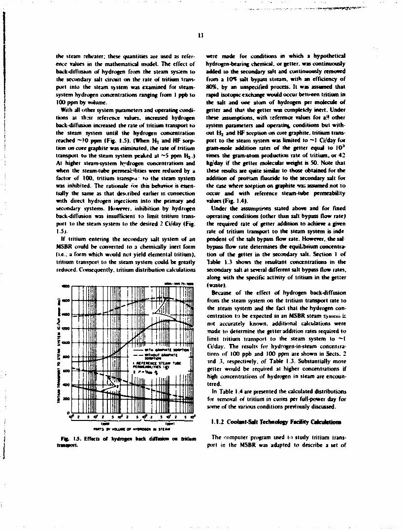
the steam rehealer: these quantities are used as reference values in the mathematical model. The effect of back-diffusion of hydrogen from the steam system to the secondary salt circuit on the rate of tritium transport into the steam system was examined for steam-system hydrogen concentrations ranging from I ppb to 100 ppm by volume.
With all other system parameters and operating conditions at thiir reference values, increased hydrogen back-diffusion increased the rate of tritium transport to the steam system until the hydrogen concentration reached ~ ! 0 ppm (Fig. 1.5). (When H z and HF sorption on core graphite was eliminated, the rate of tritium transport to the steam system peaked at ~5 ppm H j . ) At higher steam-system hydrogen concentrations and when the steam-tube permeabilities were reduced by a factor of 100. tritium transport »o the steam system was inhibited. The rationale for this behavior is essentially the same as that described earlier in connection with direct hydrogen injections into the primary and secondary systems. However, inhibition by hydrogen back-diffusion was insufficient to limit tritium transport to the steam system to the desired 2 Ci/day (Fig. 1.51.
If tritium entering the secondary salt system of an MSBR could be converted to a chemically inert form (i.e.. a form which would net yield elemental tritium), tritium transport to the steam system could be greatly reduced. Consequently, tritium distribution calculations
Fig. 1.3. Effects of hydrogen back dtffnion on tritium rrmjport.
were made for conditions in which a hypothetical hydrogen-bearing chemical, or getter, was continuously added to the secondary salt and continuously removed from a 10% salt bypass stream, with an efficiency of 80%. by an unspecified process. It was assumed that rapid isotonic exchange would occur between tritium in the salt and one atom of hydrogen per molecule of getter and tha* the getter was completdy inert. Under these assumptions, with reference values for af? other system parameters and operating conditions but without H i and HF sorption on core graphite, tritium transport to the steam system was limited to —I Ci/day for gram-mole addition rales of the getter equal lo I 0 3
limes the gram-atom production rate of tritium, or 42 kg/day if the getter molecular weight is SO. Note that these results are quite similar lo those obtained for the addition of profium fluoride to the secondary salt for the case where sorption on graphite wai assumed not to occur and with reference steam-tube permeability values (Fig. 1.4).
Under the assumptions stated above and for fixed operating conditions (other than salt bypass flow rate) the required rate of getter addition to achieve a given rate of tritium transport to the steam system is inde pendent of the salt bypass flow rale. However, the sal bypass flow rate determines the equilibrium concentration of the getter in the secondary salt. Section I of Table 1.3 shows the resultant concentrations in the secondary salt at several different salt bypass flow rates, along with the specific activity of tritium in the getter (waste).
Because of the effect of hydrogen back-diffusion from the steam system on the tritium transport rate to the steam system and the fact that the hydrogen concentration to be expected in an MSBR steam s>»»eni is not accurately known, additional calculations were made to determine the getter addition rates required to limit tritium transport to the steam system to ~ l Ci/day. The results for hydrogen-in-steam concentrations of 100 ppb and 100 ppm are shown in Sects. 2 md 3. respectively, of Table 1.3. Substantially more getter would be required at higher concentrations if high concentrations of hydrogen in steam are encountered.
In Table 1.4 are presented the calculated distributions for removal of tritium in curies per full-power day for some of the various conditions previously discussed.
1.1.2 Coolant-Sail Technology FaciHy Calcufartiora
The computer program used to study tritium transport in the MSBR was adapted to describe a set of

12
i«fa
I O - I C V * *
Sail by-pass flow rale*
( * o f MIM flow)
Getter
sail
Addition (awl removal) rate of chemical set let
(•*'*•?•»
Specific actrrity of
tritbtcd getter <Ci/»>
I.
10 I 0.1 0.01 0.001
aftac hyvbogea i 4< * 2 pf*)F;artmM
M O B * M l M l
6401
42 42 42 42 42
0.5 03 0.5 0.5 0.5
10 I 0.1 0.01 0.001
10 I 0.1 0.01 0.001
440 4.4X10* 4.4XiO* 4.4X10*
'Owe exchangeable hydrogen atom per mokcatc; molecular weight - 50. "Getter removal efficiency, 80%. rClean-metal permeabilities for steam-system tabes: no H, >x HF sorption on
graphite.
proposed deuterium injection experiments for the Coolant-Salt Technology Faciiiiy (CSTF). The purpose of the experiments was to investigate the possibility of tritium retention in sodium fluoroborate coolant salt using deuterium as a itand-in for tritium. The results ol the calculations could be applied to either deuterium or tritium for the conditions considered.
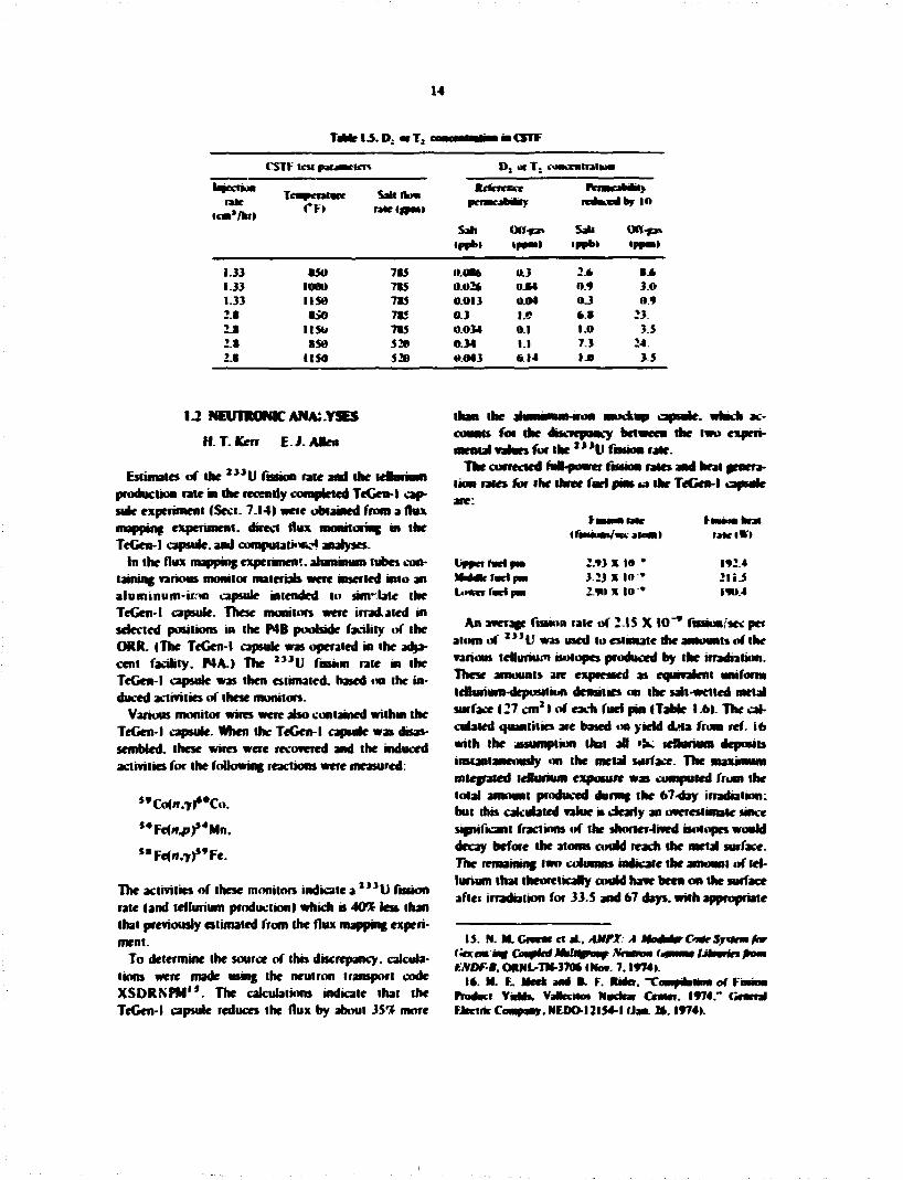
The parameters to be varied were temperature (850. 1000. I I50°F) of the loop, salt How rate (785. 520 gpm), and deuterium inieclinn rale (1.33. 2.8 cc/hr).
The resulu indicate that, for reference permeability values of the loop walb. the steady-slate concentrations of deuterium in the salt and off-gas could be expected to range from 0.013 ppb to 0.34 ppb and from 0.04 ppm to I.I ppm. respectively. For a reduction of wall permeabilities by a factor of 10 the concentrations in the salt and off-gas would range from 0.3 ppb to 7.3 ppb and from 0.9 ppm to 24 ppm. respectively. The results are presented as Dj or Tj concentrations in the salt as a function of the test parameters (Table 1.5).
mmmmmtm
13
i i
Ji
•a
i 1-M
1 i >
1 »
i s 1 i
, !
if I
i i c a
i ,
3-s:
H ts
I I' X 3 .
a*
; i i 3 - = ! s ^ s = ::555 : s - 5 5 "'~"~"" , r ~"'v;
ill? Histt W - - • n t - < s » n j O M n a n a - - - - - ' - « - - -v v v v v v v v v v
SS5SSSS|5|S77--vvvvSSSS=SSS52S
ss
ss
o e
2* S S 3
hh 33 e e o o o o e s s s s s o s e o
lJIiliiilli. .tlttlt Z Z Z Z Z Z Z Z Z Z X X X X X X X X X X X X Z X X X X X X
ZZiiZZiiZiiZZiiZfiiZiZiititiZi
.8 3 8 8 88§8§8§8§ 3 38
s o o o o o o o o o o o o s o e *aahooo'o%%"o"olo
- w r t « * i i r ^ « t » d - r*m«^*i*«*£~^fn«vi«#r>'«ajid mi
14
T « r l J D o . T ; o • • C S T F
CSTV ten paraactcrt D , or T . < iiMKratnikMi
In jectM rale
icm'/kr)
Tcauwntwc Salt A m Jtcfcacccr
pcnncaMMy nriwjtfaMM)
ic*Kcrfbr io
Sill Off-*a% Sail on-f» <ppbl tnjnO •pnbt <pf*»»
1.33 850 785 O.OB* 0.3 2 * I k 1.33 1000 785 ao2* 0.84 o.9 3.0 1.33 1150 785 0.013 0.04 O J ov 2.8 8J0 7*5 0.3 I.C * . 8 23 2.8 ItSO 785 0.034 0.1 I.O 3.5 2 8 850 520 0.34 1.1 7.3 24 2.S 1150 520 0.043 Ik 14 I.O 3 5
1 2 NEU1Y0NIC ANALYSES
H. T.Kerr E.J.AIen
Estimates of the 2 > J U fission rate and the tenurium production rate in the recently completed TeCen-l capsule experiment (Sect. 7.14) were obtained from a flux mapping experiment, direct flux monitoring in the TeGen-l capsule, and compuutioKH analyses.
In the flux mapping experiment, aluminum tubes containing various monitor materials were inserted into an aluminum-ir.nl capsule intended to sun-late the TeGen-l capsule. These monitors were irradiated in selected positions in the P4B poobide facility of the ORR. (The TeGen-l capsule was operated in the adjacent facility. P4A.I The 2 , , U fission rate in the TeGen-l capsule was then estimated, based on the induced activities of these monitors.
Various monitor wires were abo contained within the TeGen-l capsule. When the TeGen-l capsule was disassembled, these wires were recovered and the induced activities for the following reactions were measured:
" C o l n / j / ' C o .
*4Fe(i»4»)*4Mn.
"Fefir.T^'Fe.
The activities of these monitors indicate a 2 > > U fusion rate (and tellurium production I which is 40% lest than that previously estimated from the flux mapping experiment.
To determine the souice of this discrepancy, calculations were made using the neutron transport code XSDRNPM". The calculations indicate that the TeGen-l capsule reduces the flux by about 35*£ more
than the alumumm-iron mocfcup capsule, which accounts for the discrepancy between the two experimental values for the " *V ftsswn rale.
The corrected fuM-povra fission rates and heat generation rates for the three fuel pint ta the TeGen-l capsule
I fMMK/w atom) U K l t l
Vppafwttpm 2.V3 X 10 • 1924 I M n V f a r l p m 3 .23X10 •• 2 l i J Lo«cr facipM 2.TOX 10 • lvo.4
An average fission rate of 2.1 S X 10 "* fission/sec per atom of 2 , , U was used to estimate the amounts of the various tcthiriutn isotopes produced by the irradiation. These amounts are expressed as equivalent uniform teUurium-deposiiiun densities on the salt-wetted metal surface (27 cm 21 of each fuel pin (Table l.6>. The calcinated quantities are based «m yield d.la from ref. 16 with the assumption that all lis; lettunum deposits instantaneously on the metal surface. The maximum integrated leBunum exposure was computed from the total amount produced during the 67-day irradiation: but this calculated value n clearly an overestimate since significant fractions of the shorter-lived isotopes would decay before the atoms could reach the metal surface. The remaining two cuiumns indicate the amount of tellurium that theoretically could have been on the surface aflei irradiation for 33.5 and 67 days, with appropriate
15. N. M. Crcem et at. AMFX. A MimnrCn*SwUrm ft* f •A'CfnVnvnJ CoHjICv MtK^^WOft^ JVfMMM fntPMIvnf IJwRmWtn jnMIV f.NDf-B. OHNL-TH-370* I Nov. 7.1974).
16. M. R. Meek ami •, f. RnVr. Tomfitalinii of tmmm PromKi VMh. Vafccrto* Nudnr Center. 1974." Central Marine Company. NF.DO-I2154-1 (Jan. 2*. 1974).

f^ ' i- 'W^Er*'*^, . ;
iS
tlJkCMnfeMrfMbi > * * * «T<
«»»l
lkl> l«C»»W1
• *SI i f»a*7 4x>>
U » " atumvtra'l tm*sMd JJ.5 A»» *?4b».
" • T « * * * lc ' " • » * ••*Tc •**Tc • * • • ? « • , % f « • " T c ' " • f e . . . T c
'"!< ",m%€ *"U " M c , M t c • " T c t«ul
an*/ u.014/ 6.114 ass$ • . •J i OLM* 1.24 i JJ I . U 2. JO 4.52 J.2« 1.40 J.«4 l.l» O.J4*
2*14.0 1.4
1.17
Jo 0.417 7B a»2J a 2 w a7oo O.OOJJJ O.0054J
o.OI 7 a.125 0.54J 0.97I a J* J I.Jo 2.45 1.22 2,42 4.7* J.J* 1.47 J . I * 1.25 n.Jtt
2J.M
ooara 0.0SM O.OB4V Q.4US 0.IJI 0.0014 I.22J MOJ2B
«OJ2l n.t»2> O.OBOJ o.on2o
2.2*
U.OI7 O.SOI7 O.OMV 0.*7» 11IH O.rtOU 2.45 o.oJ2* I I . I D M
H.5J2I it<m2l o.wwj
4 12
*lir**ricJ *>7 4 * » j i j a *rr*p k Y « M u > p > w < i i j i ( * m * i i r VMMnr«r2 7^v j f a "Sb 4 Y K M n u l U c j > < « ^ « n v i )
cateoi 2.15*10 * I n M A f o j i u a u l »'*f. Ikal »**.* 4fv4>< fro* the n<Ki> ibK t.» Ike CI**HMJ
. Tc |i>ju»T»i n 47 4 * * » M»Mn*ili. l» * ' *Sk jM"*Tc<«l | . rKWi" ihc lo'-jcar
*uic
!*• ptcvwr»-» r. ikcrfcvtcrf
annuraace fur decay on the surface. The final vahae. 4.1 J X 1 0 " j iomscnr . indicates Uui the desam ob-fccinc'* ol - 5 X 10 ' * atoms/cm2 n » w . Tins final value i» at*>» wcH above ihr lowest cafcndaled deposition den*nie*|--l X 1 0 ' * j iomvcm'lfoc MSlIt specimens in which surface cracking «f standard IbneUoy S « » observed.'* Measured leBonum cuncentratiorr* on MSRK surfaces ren-oved after the fnul dmidown ranged fiam 0 74 to 4.5 X 1 0 ° atoms/cm2 iref. IX) .
ORKir.N tOKSl Isotope tieneratn* and Drptctiun ( i n k ) catenations nf fruion-produci concentrations were aho dune to aid m postiriadtaliun chemical analyses of Tefien-1.
l^ H K H - T I M T E I U T U R E DESIGN
J. M. forum C. T. Yahr
Thermal ralchetimg and creep-fatigue damage arc important considerations m the design of reactor systems thai wnl operate 31 t t r M e d temperatures. The
investigation desenbed n the foBonmg section B being performed under the O R M Ihcfc-Tcinperaiwe Design Program, wind) t» supported m part by ibe MSR Program, f-ium ibe rewdti 10 be ubtamed. Mnptoficd raf«.briimg rides o n be developed and • * e*ahia>ed. modriMg procedure* for apph/mg wnphfied rau-heiiing ruin to pruioiypK campuneni gmmeino and iuadmp can be eummed. and the omsertaiive apptkabnii> 01 Mrapbfied roto and procedures and «f etastk' creep-faligHe ruk» can be wsied. Although the reference material being med m theie Mudio curienif> B t)pe 304 Mamku Meet, a careful aaeMmeni of the appbea-b*iy uf the rcsolb to IfaMefloy N wtU be nude. A series of meiastic ptpe-raichetimg analyses mU he done using HaMeHoy N properties and typical USSR temperature and pressure Histograms 10 determine the seventy of the tnermal-ratdieiimg and creep-faiigue damage proMerm m the W S M fSee. I .i.2 >.
I J . I • f p W
17. R. L. Sow el JL. HSK Um SI I972.0HS\.-I*>2.pf * l 94.
I«. B. HcHAh ** H. >. Mrfor. KM thigr *rp *rh > . 197:. ( * \ l -tin!, pf
n^n - top-
im 17 I J . I . I fMaanr. The purpose of the anatyticd
studies being prrftHmed under inn task is i««>foid.

16
Rnt. mudthra, procedures for apply •% ihe samataed ratchctta* nies gneu HI ASME Code Case 1592 liet-|4|. ROT Standard P M tref. 2<H. a H RDT Standard P»-5 (ref. 21 Mo proamnes aad loadmgt prototype of those encountered m mgh-umpcijiur< reactor oom-poacat designs a t hi h identified. Second, the conscratiuf appk=abdrty of' these n k k t i a | rales aid procedures jad of clastic ciccp-fatigac rates wal probably be deawastnied aad placed oa a reasouabtt sound
The basic approach is to ptifuiai a idalndy smal maaber of ftfaW) plaaaed aad coordmaKd rigorous cbstK-pasnc-cratp ratdrtting-type analyses- The problem* beau; cuaaaed raaar froai prototypic uace* awataiinad coanmacut gtonartries aad loadings to mure banc two-aaueasioaal axaa/aaartnc problem* sprcaay coatrrurd to augment the more coandcx problem* by debucatau: the iadmdaal factors Pol deteraaat of mflaence ratchetrmg behavior m rcahsiic struciarcs. Each latjastic analysis wal iadade a complete Coat cvahnucm for accaaadated siram* aad crccp-fatiguc damage. Abo associated with each lacks-He aaah/sis are a aaaakr of clastic analyses to provide the mpul parameters rcaancd to apply the various snapbficd ratchetiiag rales aad procedarcs aad elastic creep-fatigue rales.
I J I J W I I I I -| i «T 11 i l l • ASME Code Case I5*»2 aad ROT Standard P»-5 pronde simplified rales aad proccdarcs that, at certain specified sitaatioas. can be awd in hea of a detailed iaebsoc analysis for deaioasuatMa; that the maximum accuatutatcd inelastic siraau do not exceed the specified Code Hants, la addition to the OTJoaael-Foroursfci method22 that is mduded in Code Case 1592. RDT Standard F9-4 afao alow* the osc of a modrficd Rree complete relaxation method2' aad of a detaacd one-dimensiiwul (pipe
19. Code Cat 1S92 for Secno* I I I . O n I . Xucfcar CnnmoucMs m f loa ted Temperature Seroce (draft). ASMf. l a i n and h n w c V e n d Codc.
M KM Standard F9-4T. * i mow mum for Ctmurmhom of HH-IMT Syom Commommn ml fJcmttd Trmperttwrr* (5mfp*t-mcni to ASME Code C n n 1591 I59J. 15*4.1595. —d 159*1. September 1974.
21 RDT Standard F9-51. Cmdrimn mmd ftv.edmrt for Oruvi of W * w System Cnmpomrmt m Hewmted Tempera-tmr. September 1974
22. * . I. O'Dnouen' and J. Porowski. "Ipoer Round* for An-umniaicd Stram* Due ;•» Crop Raicbetmp." J. Frenart l e w * Textmoi 9t>. IV) 54 (Aqptl 19741.
23. I. fccr. "•rkrMnfliWK fktumw <rf Thm Tobo Sabjcclcd l» iMtntH Prevwre jnd Intermittent High-Heal Khnct with ApphiMlnn to I *U-N<M.trar-Rexliir |-»cl Howcwlv" / .VMM A~L Ii)t:2*> 3*(l9fc7i
tatchcttiag) inelastic analysis to ptedict acoanubted strains in more complex structures. Both the OThmaefl-Porowdu method and the Brce complete rebxatioa method use the results of elastic catcufatinm. m fact, cuea da? oa* dancaiiwul inelastic analysis must properly reflect the dasticaly calculated primary membrane aad secondary discontinuity stresses.
A l of these liaadiikd rules aad procedarcs arc. as explained m RDT Standard P»-f (ret. 21). based on aothenuticat) imr damiuiiiiijl inelastic analyses of thin waned cylindrical vessels under sustained internal pressure with a cychc temperature gradient through the waH. The consenraiwe appMcabdity of these sinipwicd ndes aad procedures to straight pipes with axisym-metric thermal and mechanical secondary stresses has been verified through comparisons with the results of detaaed iaebstic analyses.24 These simplified rules and procedures haue also been shown to be applicable to a noule-to^awerical-sfacil aeacaeuy with axisynanetric loadings2 s - 2 * and to that-watted pipes subjected to aoaaxisyaaactric beading loads.27 On the basis of these few comparisons. RDT Standard P»-5 stales that the sinmlaied rules and procedures can. with caution. generally be appbed t" axisymmelric sheUs subjected to axisyaunetric loadings in locations where there are no local structural drscontmuities2* and to straight pipes subjected to net nonaxisymmetric bending. For the lauer case, the maximum outer fiber bending stress .misi be treated as an axisyinmetric axial primary stress w ihe one-dimensional evaluation.
24. T. W. Pkkd ei J . . "St»d> \4 Thermal I •Ichetlinr •ektmuc M l VhmtK Omp> RcoBHcmeiiiv'* Hrtft- Ttmptniw* SnarMMf Orajt* .Wrinodi for I.MVBR Compoornn (Jmrt. hop. Hep. Srpt. JO. 1972. ORNL-TM-40SX. op. 191) 213.
25. ktlthrl Amtly*% of m Axtsymmelhc \ozzk. Tcihmc.il Report K-I4l4tb». TcMyne Malerioh Rewarch. WaHkam. Mns. t teb. 28.1973K
26. I . M. r kcm and D. H. Pat. "A SimpNTicd Timl for the M m l e d Temperature ( > C I K Arol>w <>f Prowre C'umpiv nciilv" pp. 263 75 m Second Imunmtkmal Ckmftrencr on htomi Veori Techmohgy. Nrt I Dtvgn mud AnmlvUs. Amend* SucKty «l Mechamval f.npncm. 1973.
27. F. O. Werner. "A Stady «f Ihe ApphcaMity or the Smtpnfitu1 Inetetit Amiy^n Methods for AxHymmctnc Shelb •mter A%B.ymmtlnc Lnad> in fiprv and N n n l n Subjected in Rendnw. Lnad% and Thermal Shock*." onpuMnhed report. Hanford Fncmecrnu; Drvdopment Laboratory (October 1973).
2ft. A local Mracmral doconiawity is a geomelrk or material dnconimsity. web at a parlol penetration odd or a wndl fillet or notch, thai affect* the stress and tlrain dntribiitiont through only a fractional part of the wall ihickne«. Local discontinuities base no Mgnifkani effect on shed-type discontinuity dcformalmns.
17
As staled, the applicability ol these procedures is severely limited. Without justification and owner approval they cannot be used in many, if not must, .ealislic design situations. These limitations were recognized when the rules were written, but it was expected that they would be shown to conservatively apply to a broader class of structural situations as additional inelastic analyses of prototypk structures were performed and experience was accumulated.
This study will provide the basis and justification for removing the limitations placed on the appucabibly of ihe simplified ratchetting rules and procedures. The validity of the application of these procedures to regions of local structural discontinuity, to nor.axisym-metric loading on axisymmetric shell-type structures, and to general nonaxbymmelric shell-type structures (such as nozzle-to-cylinder attachments, valve bodies, piping elbows, etc.) is being systematically and progressively studied. Although these specific applications are limited by present Code restrictions, this study is to show that the procedures are appropriate for any-general she!l-type structure.
If costly and time-consuming rigorous inelastic analyses are to be avoided in design, the elastic creep-fatigue rules must be satisfied as well as the simplified ralchelting rules. The elastic creep-fatigue rules in Code Case 15')2 include the use of an approximate equation for estimating the maximum inelastic strain from daslically calculated quantities for determining fatigue damage. The fatigue curves to be used include reductions for slow strain rates and hold times. Creep damage is based only on primary and secondary stresses resulting from sustained operating conditions: secondary stresses generated by transients are assumed to relax off and thus be taken care of by the hold-time effects that are factored into the elastic analysis fatigue curves.
The conservatism of these and other possible elastic analysis creep-fatigue rules relalive to the more rigorous inelastic analysis rules is currently being evaluated by the ASME Code Working Group on Creep-Fatigue for simple cylindrical shells.1* ORNL participated in this evaluation by perfotming a series of comparative eiastic and inelastic analyses and evaluations.'0 The conservative applicability of the procedures to more p")tolypic geometries and loadings is even more uncertain. Thus, comparative elastic and inelastic creep-fatigue evaluations are an important part of the study described herein. These evaluations allow an assessment to be made of the conservatism of the various elastic creep-fatigue procedures and also help (o establish the relation between the simplified ratchctting rules and
procedures and elastic creep-fatigue rules and procedures-
13.1 J Scape «f Study. The .-Rafyticai study consists of five types of ttasiic-ptaslic-creep ralchelting analyses:
1. notched circular cylindrical shews 2 cases. 2. circular cylindrical sheas with axial temperature,
pressure, and or wall thickness variation* 7 cases. 3. prolotyptc no«le-t«»-%phencal-sl»efl attachment
IFFTF IHX mlet noule geometry) lease. 4 . prototype no/zle-t<<vbndncaJ-*heN' attachment
IFFTF IHX inlet no. degeometry) I case. 5. comparison minute cylinder (one-dimensional pipe
ralchettmgi analyses 30 to 40 cases.
These live types of analyses are described with a bnrf statement of ihe purpose of each and a description of ihe types of loadings to be applied and the analyses to be performed I Table 1.7).
These analyses are being carried on' in a closely coordinated manner by ORNL and ORNL subcontractors. The axisymmetric analyses I types I and 2) and the one-dimensK>nal pipe ralchelting analyses (type 5) are being performed at ORNL usmg the two-dimensional elastic-plastic-creep finite-element program PLACRE. The nozzie-io-sphere and n-.vukMo<ylinder analyses were subcontracted by ORNL to two U I F B R component manufacturers experienced in per forming complex inelastic analyses on realistic component geometries. The MARC computer program is being used for these cases, and a thrc-dimensional element idealization will be used to properly represent ihe reinforced junction region in detail.
Although the analyses are being performed al different locations using different computer programs, the analysis efforts are being join:ly planned and coordinated by the several participants. Of course, it is imperative in a study of this kind that ihe various inelastic analyses be completely compatible with one another. As far as possible. Ihe mesh layouts and the degree of mesh refinement are similar in all cases. Identical constitutive relations and material behavior
29. The most qucUKMubic aspect bra* cvanmrd m thtt evaluation is the *tre» vitac wed in ihr creep damapr tfefcnniiulion.
JO. J. M. fnram and W. K. Sartnry. "Afcih/tical Stad> nl t.bMk Crccp-r-'alipie Des*n for ASMK Htrtt-lcmpctiiun Code Case." HttfrTtmprrmwrr Stmrnrtl Propi Methmh for I.MrBK Camprmrnit Qmn hagr. Rep. Mm. 31. 1914. ORNL-4977. pp. 1117 V*.

IS
I*1
Hi i
liii
I*1
it
if1
ii mi
IS m iiilif
lift! i Hill
« :
J!
i
! I
U) iti
Sffllii. i! 1
llillilll
u. St
$.11 Hi
ipi!' iiii! ii 1;!
iiiiii in !!i it
HHIf
V i! I r il II, Ifl||fil||
!
r :
2 J U$
if--is : if- ? •
•4 I
I

^•'^•^Mm^-i'.' . . . . .„_;- . ~-5iii*J'a*t%E.S^;««3S^
BLANK PAGE
if-.:
p j t - u ' U - X J ^ I . ^ . — m..w» -.-^wtnft.^.-."BH|».jwlwwpqwBwag!

w
p
ill hlli
iijii itilj
IB mi!
ii Si
HII
iiU iflt
'Hit I A !i i! 8 ! ! s .
!l is
I; • •
%
iS - * i •» • •* **i a t \ « « K
I'ill!
iil LP, S i l l
filial ill!!!
:S?;*r Mils****
i l l
Hi! j l
J U*
\
2

19
representations are bemg used m aH cases. The constitutive conations be i f used are those ictummrnded m RDT S u d a n i P»-5 |ref. 21). and the physical awl rnerfiamtal properties were obtained from the Nuclear Systems Materials Handbook.''
To i n we that the inelastic analyses performed by the
each group b perfunanng a* identical analysis of a siranafct pipe subjected to an internal pressure and to repealed iMenui sodium donnuhocin fohWed by hold periods- Five cycles arc beat analysed m this benchmark problem. Any significant deJferences between the various results wnl be resolved before the final meraslk analyses arc ran.
As previously mentioned, each jneiastic analysis war be acenrnpanird by a number of aaVukmal juppnrting analyses. In many of the cases, a transient thermal analysis is remmed. Cbnnnan neat transfer and physical properties are being nscd in a l the thennai analyses. Abo. each metasuc analysis wm bane a series of connpamon elastic analyses for the individual mrchini cal and ihemal loadings at different points during the transients. Primary and secondary stress magnitudes and elastic strain concentration values from these elastic analyses wnl be used in applying die smmwfied ratchet-ting rates and the elastic creep-fatigue rales at various critical cross sections or locations.
Each inelastic analysis wul include a determination of inelastic strains during each hold period as Ibuows:
1. strain averaged tbrough die thickness at critical locations.
2. surface strains at critical locations due to equivalent linear distributions through the thickness, and
3. rruximurn strains at critical locations-*2
The inelastic strains of interest are the maximum positive principal strum computed from die strain components as specified in Code Case 1592 guidelines -Each mefastk analysts wH abo include mebsfk creep-fatigue damage calcinations al critical locations using Code Case 1592 rules.
Experience has shown that at least ten cycles of loading should be analyzed to determine the trend m ratcheting behavior. Thus, all the inelastic analyses wnl be for a riuniniam of sen hading cycles, except for the thrce-dunensioaal analyses, where cost makes ibis
31. AwfNW/ Sjnlrw MMvuw MMUnovw. roc /. ftenjnv Eufr. T1D»JM66. Hmfoni FngnMcrnu. l)ewJounKfii Ljbno-mrjr.
32. Tnc umeufiM nroceunrcs wul awn jeurvM incx a n t jXmm unaniiftej. each of which mutf wecf the icwedwc M J U I bawl mrafnal m Com Cam 1592.
number tutaJry impracticable. HohJ prriods wiH be 200 hr.
Analytical results n i l in a l cases include plots of selected stress-strain histories, strain accumulation vs lime, and creep and fatigue dinruy auumuhtion vs
The material assumed for a l analyses is type 304 itainam steel, utaumum temperatures are UOO'F.and sodium downshocks are from 1100 to 800°F.
The five different types of cbstk-plastk-aeep ratchet ing analyses arc discussed separately bekw:
Type I. MHchoLtfUmkhMlihdl analyses. The Imitation that the junphfted ralcbetting rales cannot be apphed in regions cimlunmu, local structural discontinuities has been criticized by some as being overly conservative, uecause of tue localized nature of a local dBcoatuMuty, gross ratchetting v i not be significantly affected in such legwns.
Shalow notches are representative of severe local discontinuities- Thus, a notcted-cyrmder geometry has been chosen to evaluate the effect of a local discontinuity on ralcbetting and to verify, if posnMe. the conservative appbcabmly of simplified ratchetting and crcep-fafJgue rules and inodciing procedures. Two problems, with variations in the notch geometry and/or the loadings, arc planned. By comparing the predicted ratchetting in undisturbed regions of the she! with the ratchetimg strains across the shell at the notch location, the effects of the localized notch can be assessed.
Although the notched cylindrical shell is geometrically ample, it represents a sizable fmite-element problem because of the mesh refinement required to represent adequately die notch region (see ref. 33 for a description of a shniar fimte<teineni analysis). The length of the cylinder moJeied wnl be sufficient to eliminate any interaction between the notch effects and end discontinuities.
The loading wdl consist of an internal pressure, an axial load (to magnify the notch effect). *n& a repealed internal sodium thermal downshock foBowed by how* periods. The loading magnitudes win be chosen so that a modera'e amount nf ratchet ling strain is predicted in the undisirubcd region of die cylinder by a oue-dimensional pipe-wall ralchetting anatysis.>4
33. C. w". Lawton. "Stain Conwcntialioa Ujrjmsf in a Norchce Horn* tar Sabfrcsof to Own." M>. 253 « m Jft..nv ntnvnnnMMf Cow ffimw on r^raunr wtoti Tern-Mnrom7. nn I utttpt amf AttttwtM. American Society of Mcchnnval riujnwsrv IV73.
34. In ihuuinw, loading cMUtoout for a) the meUMk jmt fw. an ltnuuM w * be mane to nwumw* * t ntcnnnng U T M B wirhnal ftllnni into ittt K, or H, repom of inc RjC-iyni afetfjln ittt 11).

20
Probably, the rente of tbe inelastic analyses wil show that, euen in the reUtmty severe case of a notch, a local dtooatimrity has a mghgwh effect oa ratchet-ting. If the effect is sot aeghgibk, the ana wnl be to develop the proper modeling peoctdmu for usiag elastic analysis results as iaput parameters to tbe ijwpbfiid rales to obtain conservative inelastic ratchet-ting strata pndktioas.
Type 2. QanaVstnfihra' aaafvsci The ratchetrJag behavior at a gram poiat • a genual shell-type structure is aipeadtat aot only oa the condition! throagh tbe wal at that locatioa bat also oa the bebwioi at other pomts. Adjacent sectioas watch arc thicker or thiaaer, hotter or colder, etc, may drive the ratchettmg strain at the poiat being luntidrwd to hsgber vaunts than coaditioas at the poiat would iadkate, or they taay ounmasa the ratchctrjag to saankr values than would be rndkated. Likewise, the elastic foaow-wp associated with wMchanirn aad/or thrtBHly anJntrd discontinuity stresses CM affect ratchctting. Of coarse, it is these stractaral interactions that interfere with a straightforward application of the smndiiied one-daacasional ndcs to complex stractarcs asiag oaty rhe conditions through the wan at the
Probably, with appropriate nwdcbng rales. condition* at injur at sectioas can be cowered by asiag eiasrk aaatysis results. As aa cxanspk of a special aiodehag rate. Code Case 1592 states that ia asiag the simplified ratchrttiag rates, "any stresses with clastic foaow-up (eg., secondary stresses odw than those caased by radial temperature variations) should be iadaded as primary stresses for parposcs of predicting ratchetrjag strains unless c4herwise justified" This appears to be a conservative rcojairciaent that HUJM be adequate r m for geaeral aonaxisyaaaetric situatioas. However, no general experience with applying this proctdare exists.
Tbe axisyutmetric ijhadn piubhau arc to help delineate the effects of the iaiividual fmors, discussed above, that affect ratcbetting at a given poiai. Results from das type of problem wil provale a better aadcrstaadmg and asatssmcai of Hat retails of the fTOtotypk aozztMo-sphcrc and noak-to cylinder prubkim (types 3 and 4).
There are four different types «t cylmdrical sbeX proHkms. The first, type It. n a cyhnde* with a kmlucd step Htcrcssc in wall thickness. This geometry is intended to represent, in a very simple way. a reinforced junction region, fey property dioosiag the pressures a, and » 5 . pressore discontinuity stresses can be included or eliminated, fn one analysis, the transient loading comes from repeated mleraal sodium thermal
dowashocks- Became of the varying cooling rates in tbe
ties occur during the transients. In another analysis, the transients are produced by anew thermal gradients pivoted about the nadsarface. la this case, the ther-•unity induced discontinuity stresses other than those caased by the radial temperature variation are etaai-aated. Four probkaa, of type 2c are pfwmtd.
la problem 2b there is no walMakfcaess discoatma-ity. bat there is aa abrupt change ia the nwajnitadr of the bam through tat nnt temperature transient.** That the two halves of the cylinder wal ratchet at different rates, aaVming a bask cxjmiaatioa of the driving or amsuaauag effect of adjacent regions.
Problem 2c is a uniform ijlhalii with a nonlinear axial thermal gradient. In cases where the tempeuturc dutiamtiua tends lo create high discontinuity stress, a simplified ratcheting anityiii any not apply1* This aroulent war exanuae 0ns aensarcaty.
Fanjay, problem 2a* is a cylinder bant in at one cad. auilt-ia cyajaders have beta repeatedly cited as aa ixamph of clastic fowow-up, and thas the problem is mchnfcd here to provide a test of both ratcbetting and creep-fatigue procedures under sach conditions.
A study of problems of the baft-m cyhadei type is expected lo provide a clearer and more defcnsmh undtrtfan'li.ig of modeling rules to be used in applying the iJaiphThd ratcfettiag procMurcs- The rules derived from these probkws wal be appfc.* to the prototypic stractarcs ia problem types 3 and 4.
Type 3. Sozzte-to~spmtrm.ml jJatff mmfytu. The
m nleatilymg ways of coastrvativcly apptymg sBBpb-Ikd prutedaru to general structures. Here, a nou-axisyauartric load - a beading moment applied to tbe nczzk - is applied to aa axisynanetrk shcB-typc structure. IVobably. the method of treating net bending of a straight pipe that is given in ROT Standard F9-5 could just as w& be applied to any axuymmrtric shell-type structure. In fact. Code Case 1592 states that ~nonaxr/mmtlric loads sach as beadiag of a pipe or vessel may often be conservatively mefuded as axnym-metric toaas and the present rates may be aaaned. Tbe nook-tt) jphru analysis is intended to check das
To be realistic, the geometry to be anafyard is dot of the FFTF IHX iakt msofc. The detaib of the junction region arc to be accurately modeled in the fmte-
M. Tm M M M Q * O AMIS *M rrnUmi U ami 2a «f TaMr 1.1 nmefy wmrasn aw jinniiaiwn at »•» aval hot (law » at mat in At ananas jwjfyws.

21
dement represealatioa- la addition to the sustained nozzk bending moment, the loading wal consist of an lateral pressure aad a repeated internal sodiaai ther-M downsbock fohowed by bold periods. The magm-lades of the loads were chose* to produce Moderate ratchrttja- ia the membrane regions of the nozzle.
ThB proiiem. even though in axrsymmetrk gyomclry. wal require a rumples: aad cosily three-dimtniinwil analysis, '"he inelastic ratchettiag evahs»iM»s aad the inelastic cecp-faugue damage calculations wal be carried out »7oss the thickness at varioas circmafcfcutiai pontioas jroand the shell aad at discrete mendtoaal
and enduy in the membrane region of the sphere.'* Pauameii from the elastic analyses w i l be i t quired at these same locations.
It is exacted thai the resafts of the aozzir-to-spherc analysis, together with the results from the type 2 ryliadci aadysis. win demonstrate that the simplified proccdarcs a n be conservatively applied to the case of an axisy-jm i r k vessel with nuaaxisymmetrk loading aad also wi i explain why the procedures arc conservative.
7>pr 4. ? nzxk-un.) Imbkml ihett urm/rsrs. The pro-t«ypK norile-to-cylindrkal-sheR problem is the final step in lb; progressively mure awnptex series. It leprcseMs « general shdl-type structure, but at the same lime I I D a iopcal extension of the earlier ptubkwu in the series.
The gcoMclry wal be that of the FFTF IHX mlet nozzle, aa>i in the transverse cross section .«f symme:ry Hhroagh t Mt nozzle) the dimenions wal he exactly the same as f« r the nozzle-io-spbeie problem. The loading wal be an aul-of-pbae bcndnig moment apphed to the nozzle. :n intemal pressure, and a repeated mfcmal sndmm t crmal aWrehnck followed by hold periods. The magnitude* of the loads * * he exactly the same as those used far thr n •zzk-to-sphne analysis.
Of course, this problem is completely thrce-dunensinnal. T<> reduce the problem sue. symmetrK boundary enndtimm. representative ni a membrane report, wdl be taken at either end of the cyhndncai shell. In irm way <mly half of the structure wal need to be considered. As in the case nf thr rMv/tc-to-*phcrc attachment, the (unction iramiitnn report and reinforcing wdl be teahslicaily modeled. The n»«/k* wdl he
3*. A t a r T i m i Intel* M liar xnr/trt tmi ftutt • : • hr WKim4ri H I Ike fwoc-thnum n m k l in r i M « j w t > i «f ww w*ii 4w hrtutmr ••WntsoVa' h> Ikr ranrlimi ret** ! aWn*-tmrnnrv
long enough for a wdMefiacd membrane region to be
ladastk ratcheting s id creep-tatifue damafe evalua-liocs wal be carried out through (be thickness at points along; laves defined by planes containing the axis cf the nozzle. The longitudinal pane of symmetry, the transverse pbme of symmetry, aad at least oae JninnwdiiH pbac will be examined- Parameters must be obtained from the associated clasik analyses for each of the
Possibly the results of the m*zk-to<yirsder analysis wal provide the final demonsiration of the applicability of the simplified procedures.
Type 5>. Mfimt t i n m n r (one inme renown/ m>r-itttkmmg) aaafyjex The imiastk pipc-fatdaMlmg analyses ucH be used in a numbu of ways throughout das study. First, pipe-ratcbetiing cu-kubliom wiB establish the swabmty of ihe loading magnitudes chosen for each melastk analysts problem.
Second, a number of analyses wal establish hues of coastatu ra'chet straw for each cycle of loading (hold time * 200 hi) on a hater- or Bree-fype diagram. Although previous ORNL studies have shown thai a given point on the Brcc-iypc dagram (characterized by the maximum varus of f and Q during the cycle) does nut haw a completely iraiaue value of accumulated straw associated with i t . ' ' these •ree-type plots wal be wed m making first-puss correbiions aad comparisons.
Third, critical regjou identified by the eiastk analysts associated with each problem w i l be examined by ortc-amcroioaal ptpc-ralchetlmr catewbtiom that are tailored specifically to the conditions at that point b» various potential modeling procedures. The coned parameters to he modeled, and the method of modeling. «riR be identified by comparing these final one-dirncnsional analyses with the metasfk results at the critical locations in each problem.
I J . 2 tn<lam^AaFlyses«^.lC5Kr>aw;Sabjrrtedlu
A scries «tf four or five detaacd tftciastk analyses wul he done to examine the severity of the thermal rafchelimg and creep-fatigue damage that wal be encountered m the MSBR. The araiyses wdl all be done on axisymmetrically loaded pipes suh|c<ted to interna1
pressure and transieni radial irmprratine drslnbuiions.
17 Ktkumcr 14 4h»l»l«>l tkj" ifcr x n m n U l a l U n a fnr 4 ftttm * ' a u x « M I tf«M\ •bs*""'* " • '** * J " rtnrkms* ••oe " • '»e Irjalini r tr l r

22
The temperature and pressure histories as well as the pipe sizes will be typical of those expected in an MSBR. The temperature dependence of the instantaneous coefficient of thermal expansion, thermal conductivity, heat capacity, and heat transfer coefficient as well as as the mechanical properties of the Hastdloy N will be taken into account. The two4imensionai elastic-
plastic-creep finite-element program (PLACRE) will be used to perform these analyses. The results of these analyses will allow an assessment of the applicability of the simplified methods study described in the preceding section to Hasteiioy N. Abo. these results will help define the magnitude of the high-temperature design problem in an MSBR.
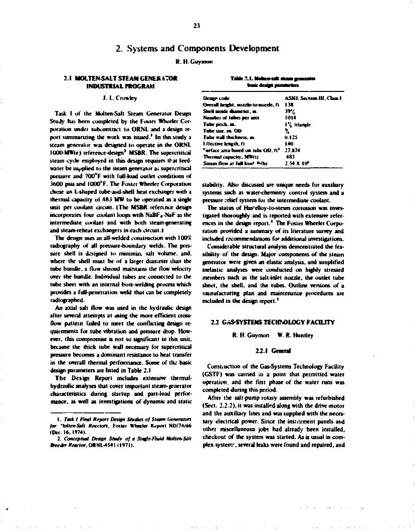
23
2. Systems and Components Development R. H. Guymon
2.1 MOLTEN-SA1T STEAM GENERATOR INDUSTRIAL PROGRAM
J. L. Crowley
Task I of the Molten-Salt Steam Generator Design Study has been completed by the Foster Wheeler Corporation under subcontract to ORNL and a design report summarizing the work was issued.1 In this study 3 steam generator was designed to operate in the ORNL IOOO-MW(e) reference-design2 MSBR- The supercritical steam cycle employed in this design requires that feed-water be supplied to the steam generator at supercritical pressure and 700°F with full-load outlet conditions of 3600 psia and IOO0°F. The Foster Wheeler Corporation chose an L-shaped tube-aiid-shell heat exchanger with a thermal capacity of 483 MW to be operated as a single unit per coolant circuit. (The MSBR reference design incorporates four coolant loops with NaBF4-NaF as the intermediate coolant and with both steam-generating and steam-reheat exchangers in each circuit.!
The design uses an all-welded construction with 100% radiography of all pressure-boundary welds. The pressure shell is designed to minimize salt volume, and. where the shell must be of a brger diameter than the lube bundle, a flow shroud maintains the flow velocity over the bundle. Individual tubes are connected to the lube sheet with an internal bore-welding process which provides a full-penetration weld that can be completely radiographed.
An axial salt flow was used in the hydraulic design after several attempts at using the more efficient cross-flow pattern failed to meet the conflicting design requirements for tube vibration and pressure drop. However, this compromise is not so significant in this unit, because the thick lube wall necessary for supercritical pressure becomes a dominant resistance to heat transfer in the overall thermal performance. Some of the bask design parameters arc listed hi Table 2.1
The Design Report includes extensive thermal-hydraulic analyses that cover important steam-$enerator characteristics during startup and part-load performance, as well as investigations of dynamic and static
(2.1. ska
Design-one Ovcnl height, nozzle-to-nozzle, ft Shell node diameter, in. Number of tubes per anil Tube pitch, in. Tnbe size. in. OD Tube wall thickness, in. I ftecttve length, ft Surface area based on lube OD. ft' Thermal capacity. MWlt) Steam flow at fun h»<< iWhr
ASSSE Section II I . Class I I3S »'/, 1014 I "4 triangle /« 0.125 140 27JI74 483 2.54 X 10*
1. Task I Final Report Design Studies of Stem (ieneraiors for 'Mten-Sall Reactors. Foster Wheekr Report ND/74/66 (Dec. 16,1974).
2. Conceptual Design Study of a Single-Fluid Molten-Sell Breetkr Reactor. ORNL-4541 (1971).
stability. Also discussed are unique needs for auxiliary systems such as water-chemistry control system and a pressure relief system for the intermediate coolant.
The status of Has'elloy-to-steam corrosion was investigated thoroughly and is reported with extensive references in the design report.1 The Foster Wheeler Corporation provided a summary of its iiterature survey and included recommendations for additional investigations.
Considerable structural analysis demonstrated the feasibility of the design. Major components of the steam generator were given an elastic analysis, and simplified inelastic analyses were conducted on highly stressed members such as the salt-inlet nozzle, the outlet tube sheet, the shell, and the tubes. Outline versions of a manufacturing plan and maintenance procedures are included in the design report.'
2.2 GAS-SYSTEMS TECHNOLOGY FACILITY
R. H. Guymon W. R. Huntley
2.2.1 General
Const, uction of the Gas-Systems Technology Facility (GSTF) was carried io a point that permitted water operation, and the first phase of the water runs was completed during this period.
After the salt-pump rotary assembly was refurbished (Sect. 2.2.2), it was installed along with the drive motor and the auxiliary lines and was supplied with the necessary electrical power. Since the instrument panels and other miscellaneous jobs had already been installed, checkout of the system was started. As is usual in complex system", several leaks were found and repaired, and

24
difficulties with some equipment and instrumentation had to be resolved.
The loop was filled with distilled water, and circuu-tion was started on February 10. 1975. Since the pur po&£s of the tint tests were to check salt-pump shall deflection and to obtain oilier data on pump characteristics, the loop-bypass line was blanked, and the entire flow was directed through the main loop, which contains a venturi flowmeter and a variable flow resiricior The salt pump was operated at speeds of SOO to 17*NJ rpm and at flow rates up lo 840 gpm with various selling* of (tie variable 'low restrictIK. The information obtained indicates that the 11^,-m-dum impetki presently in the system will prov.de the design conditions of lOO-ii head at 1000 gpm. The power data show thai the 75-hp drive motor will have to be overloaded to about 125 hp to provide GSTF design conditions with fuel salt. Motor design and performance data indicate that the motor probably can be operated with this large overload. Thermocouples have been located on the motor windings to measure the heating effects oi the proposed overload condition.
2.2.2 Mark II ramp
The critical frequency of the Mark II pump rotary assembly was investigated to ensure that the pump would operate satisfactorily at proposed rotational speeds up to 1790 rpm. The assembly was mounted in a cold shakedown test stand and vibrated to evaluate the critical frequency. An MSRE coolant-pump impeller weighing 29.4 lb was mounted on the shaft for these tests, since this type of impeller is needed lo meet GSTF flow conditions. The critical frequency occurred at 38 cps, which is equivalent to a rotational speed of 2280 rprn f Fig. 2.1). The maximum GSTF pump speed will be 1790 rpm. when ihe pump is operated with no fluid in Ihe pump bowl, so the pump should be satisfactory lor the intended service. For comparison, the vibration testing was repealed using an MSRF fuel-pump impeller weighing 39 lb. The critical frequency was lowered, as expected, and occurred al an equivalent speed of 2040 rpm with the heavier impeller. Similarity, a test run without an impeller on ihe shaft raised the critical speed to mure than 3000 rpm.
After vibratici testing was completed, the pump rotary assembly -vas disassembled lo replace the ball bearings and mechanical face seals. Although Ihe Mark II pump had previously been operated more than 16,000 hr in a test loop in Building 9201-3. the bearings and seals showed normal but not excessive wear.
Fig. 2.1. Criaxa) f m t T j tat of Ma* I I aaMp ivory
Shaft scoring (about % in. deep) was found in the narrow annulus of ihe shield plug when the Mark II rtMary assembly was disassembled. The shaft scoring must have been caused by accumulations of fro/en sail mbi from within ihe pump lank. Previous prttgress reports showed that plugging t>( Ihe pump-shall annulus had occurred al least nine limes and was troublesome during Ihe previous operation Similar problems are not expected in the GSTF. since the sail spray ring within the pump bowl will no longer be in use. The pump shall was not seriously damaged by ihe scoring action and wa.% reused as is: no damage was found on the stationary annulus wall within the shield plug. Record photographs of Ihe scored shall and shield plug were made. This shaft scoring, due lo misi accumulation and freezing, must be considered if future molten-sail development returns to the use of a spray ring within the pump bowl.
The cleaning facilities in Building 9419-1 were reactivated after salt deposits were found within the Mark II pump. The fuel-salt deposits were removed by use of a tHr oxalic acid solution thai was heated to about 94°C. Soaking periods of from 24 lo 4H hr were required lo remove the salt deposits. After ihe cleaning, beryllium and alpha contamination were found lo be within acceptable limits.
Attempts lo dynamically balance Ihe Mark II pump shaft-impeller subassembly in the iiCCND shops were unsuccessful, because the large overhang of the impeller prevented satisfactory shaft rotation on ils two bearing surfaces while mounted horizontally in the balancing machine. Therefore, a portable balancing system was used which permits dynamic balancing of Ihe pump
25
rotary assembly as the shaft rotates vertically in the cold shake«*u«..i test stand. The pump shaft, with new bearings and reiapped seats, was balamntd at 1500 rpm and was operated satisfactorily *bove 1790 rpm immediately after the balancing,. However, the pump shaft repeatedly went out of balance and vibrued excessively after operating sufficiently long for the bearing housing to approach its normal operating temperature in the cuM shakedown test of about I I 0 * F . The excessive vibration was found to be caused by an interference (it between the bearing-hoiBmgbore and the outer races of the lower pair of bearings. The interference fit prevented axial movement of the lower bearings as the bearing-housing temperature increased to the normal operation temperature. Alchough small, the temperature rise created differential thermal expansions and shaft bending of a few thousandths of an inch, which in turn led to Urge dynamic imbalances at the desired operating speed. The bearing-housing bore was increased by 0.003 in. to a diameter of b.694 in., which corrected the problem.
The pump was reassembled and operated satisfactorily at 1775 rpm for a period of five days in Ihe cold shakedown test stand. During cold shakedown testing the oil-seal leakage rales were also found to be acceptable with no measurable leakage from the lower seal and about 10-cc/day leakage at (he upper seal. After cold shakedown testing was completed, two eddy-current probes were installed and were calibrated for future jse in measuring pump-shafi deflection during water testing. The Mark I I rotary assembly and drive motor were installed in the GSTF on January 7.1975. for initial water testing.
When Ihe pump rotary assembly was removed from I he pump bowl on February 20. after the initial water tests, scoring of ihe outer diameter of Ihe impeller inlet hub was present. This scoring occurred as a result of shaft deflection, which exceeded the 0.034-in. radial clearance in ihis region. No significant damage occurred from the rubbing of the impeller against the stationary labyrinth surface at the pump inlet. Based on the information from ihe shaft deflection probes. Ihe clearances were increased lo ihe following values:
Upper labyrinth 0.066 in. radial Lower labyrinth 0.072 in. radial Impeller hub 0.082 in. r.dial
To allow for the additional founlain flow created by the larger clearances, eighteen '/|«-in.-diam holes were added which lead from the labyrinth-fountain region lo ihe pump lank.
223 Pl—in—ilii
To evaluate the efficiency with which circulating bubbles are removed from water or salt in the loop by the bubble separator, the void fraction do*vn>iream of the bubble separator must be measured. A pr'jject decision had been made in 1972 to employ an exisung densitometer for this purpose. The densitometer had been used in 1965 at the MSRE and consisted of a 30Ci ' 3 ? C s source located in a colimated shield on one side of the 5-in. pipe and a shielded scintiUauon detector on the other side of the pipe. The detector and associated electronics were restored to operational conuition, and tests that simulated the intended operating mode were made in the Instrumentation and Controls Division. It soon became apparen. that signal noise and drift were very high compared with the small change in signal expected from changes in void fraction. Subsequent upgrading of the electronic components has produced onfy limited improvements.' Data from the simulation tests indicate that the error in measured void fraction (with water in die loop) would amount to an error of about ±5% in the calculated bubble separator efficiency with a helium input flow rate equivalent to 1% void traction at the cote ccnlerbne. This error would increase as the helium flow rate is decreased and would be about ±25% at rates equivalent to 0.2% void fraction at the core centertine- During salt operation, these errors would be reduced in proportion to the densities and would be about ±1.5% and ±8% respectively.
Some improvement could possibly be obtained by periodically interrupt*ng the gas flow to check the zero output of the detector and by inserting shims to calibrate the detector span. Another possibility is to intermittently impose a constant gamma flux directly on the detector to provide calibration data.
2 J COOLANT SALT TECHNOLOGY F A a U T Y
A. N. Smith
During this report period, the recommisskming of the CS7F was completed, some equipment modifications were made, and the shakedown of the system was continued.
The system had been held under a static inert-cover-gas pressure since the shutdown in January 1973. In September 1974, Ihe cover gas contained 58 pCi of
3. Personal correspondence, R. L. Shipp to R. H. Guymon, Mar. 4.1975.
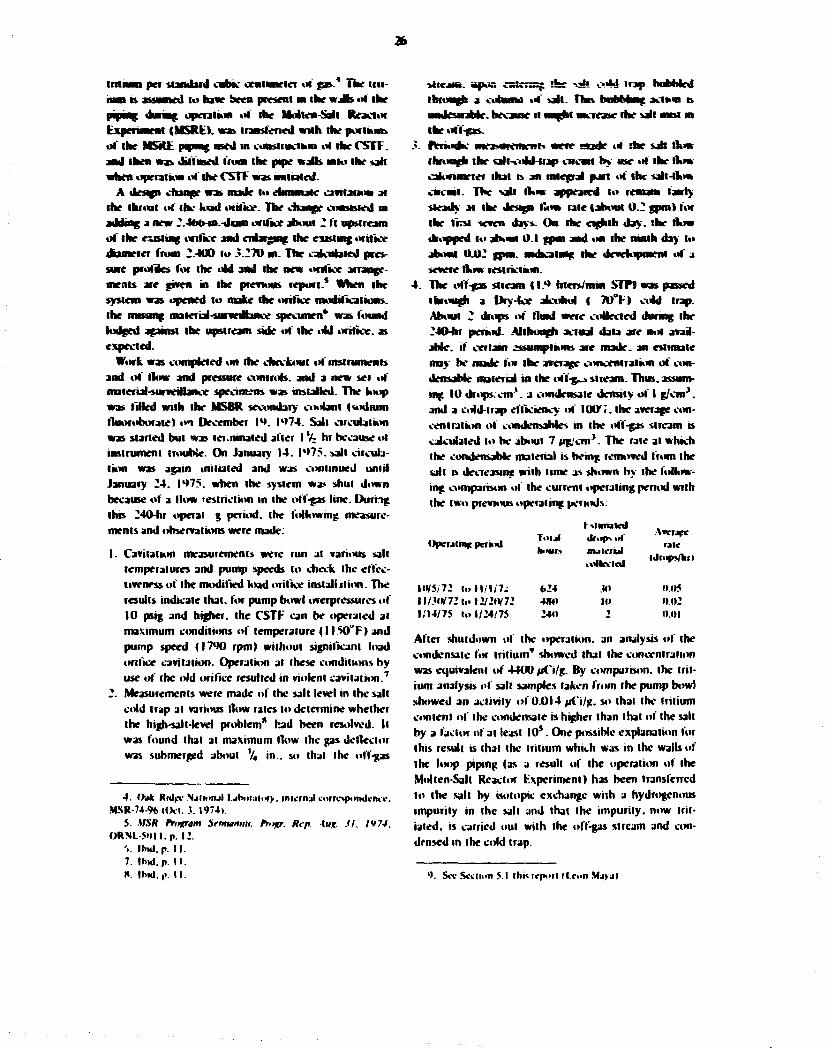
26
tmnan pet standard cubic centimeter ul gas. The ini-rwni n assumed to have been present m the walls of the pining during operation of the Molten-Sail Reactor Experiment (MSRK). was transfened with the portion* of the MSitli piping used ui construction ** the CSTF. and then was diffused Iron the pn>e watts mto the salt when operation at the CSTF was unrated.
A design doner was made hi eununjie cavitation at the throat of the load orifice. The change constaed m adding a new 2.46b-M.-diani tmllce about 2 It upstream of the existing orifice and enlarging the extstmg orifice dometer from 2-400 to 5.270 m. The calculated pressure profiles lor the old and the new onlke arrangements are given in the previous report.* When the system was opened to make the orifice modificaiions. the messing material-survedlance specimen* was found lodged against the upstream side of the old orifice, as expected.
Work was completed on the checkout of instruments and of flow and pressure controls, and a new set of material-surveillance specimens was installed. The loop was filled with the MSBR secondary coolant Isodnim tluoroborate) on December I*). I*>74. Salt circulation was started but was lei .nutated alter I % hr because of instrument trouble. On January 14. I*>75. salt circulation was again initialed and was continued until January 24. 1^75. when the system was shut down because of a How restriction in the off-gas line. During this 240-hr operai g period, the following measurements and observations were made:
1. Cavitation measurements were run at various salt temperatures and pump speeds to check Ihe effectiveness of the modified load orilice install Jlion. The results indicate that, for pump bowl overpressures \t( 10 psig and higher, the CSTF can be operated at maximum conditions of temperature {I I50°F| and pump speed (I7°0 rpm) without significant load orifice cavitation. Operation at these conditions by use oi ihe old orifice resulted in violent cavitation.7
2. Measurements were made of the salt level in the salt cold trap at various flow rates to determine whether the high-salt-level problem" had been resolved. It was found that at maximum (low the gas deflector was submerged about % in., so that Ihc off-gas
4. Oak Rulec NjHonjI l.jb»r;i!or>. inicriul lorropimdcrHi.-. MSR-74% |(Xt. J. I974».
5. MSR fnifram Semunnu. Pritgr. Rep. -In*. M. IV74. ORNL-Soil.p. 12.
'_>. Ibul. p. M. 7. Ihid.p. II . ». Irml.iv II .
MtejM. apus cstensg the -jk C"*l trap hobbled through a cokunfl of sail. Ttus bubbhng actum rs undesirable, because it might increase the salt mm m the tiff-gas. rVnodW measurement? were made o< the sab flow throogft the tall-cold-trap CMCM by use ol the How calonmeter that is an integral part ol' the salt-flow cucwji. The vail How appeared to remam fairly steady at the design How rale (about 0.2 gpml for the first seven days. On the eighth day. the flow dropped to about 0.1 gpm and on the nmth day to about 0.02 gpm. nufccaling the development of a severe flow restriction. The off-gas stream (I.** hters/mm STFl was passed through a Dry-lev alcohol ( 70°F> odd trap. About 2 drops of fluid were collected during the 240-hr period- Although actual data are not available, if certain assumptions are made, an estimate may he made for the average concentration of condensable material in the off-g-» stream. Thus, assuming 10 drops/cm1, a condensate density of I g/cm*. and a cold-trap efficiency of I00 ,<. the average concentration of omdcnsaMes m the off-gas stream b calculated to be about 7 ug/cm 3. The rale at which the condensable material is being removed from the salt is decreasing with lime as shown by the fottW-ing comparison of the current operating peroxl with the two previous operating periods:
OpereliH£ pcmnl
W/5<72 t » l | / 1 / 7 . : ll/.?«V72t«tl2/2tV72 1/14/75 to 1/24/75
Total h»vr>
624 4JMI 240
i %tmuted dfopt of nuicrul toikvlol
JW III
•»
Awrarc rale
Idrops/liii
0.05 0.02 0.01
Alter shutdown of the operation, an analysis of Ihe condensate for tritium9 showed that the concentration was equivalent of 4400 pCi/g. By comparison, the tritium analysis of sail samples taken from the pump bowl showed an activity of 0.014 pCi/g. so thai the tritium content of the condensate is higher than lhal of the salt by a factor ol ai least 10 s . One possible explanation for this result is that the tritium which was in the walk of the loop piping (as a result of the operation of the Molten-Salt Reactor fcxpcnmeni) has been transferred lo the salt by isotonic exchange with a hydrogenous impurity in the sail and that the impurity, now inflated, is carried out with the off-gas stream and condensed in the cold trap.
'>. Sec Sciiion 5.1 this report (Icon Mjy.il
r. After shutdown the system was ended to fo*«u icm-
pcrjiure and flooded w«b x p a The matenai-sarveiNaacc specimen hufder was removed from the ham. aad. » M I k oar of ibt previous operaoag period, the upper specimen was aassmg aad & presumably lodged somewhere anwV ihe loop pn**g- The •*-nunaag iw<> specaaeas had lae sbmy. etched appear-awr typical lor iMgb-teaa^eralarc service with flaoro-bneale salt. 1" Both the oif-ga* system and the sah-cold-tiap sail-flow circuM were exaaaacd lu dctermme the C W I A lor Ike flow restrictions. The folowiag » a JI—imry uf the (mimes, aad the re aria d actions that were taken:
The lop flay aad auegral odd finger were removed from the salt cold trap. The mteriur surfaces at aad aear the top of the trap were uniformly coaled with a white soud (Fig. 2.2} that was subsequently fuaad lo be NaBF 4. The ^.-va-ID off-gas Mae leadmg from ihe trap was completely plugged with the same maienal. The plug was located at the trap outlet aad was only abu it %m. long. The gas hae downstream of the plug was relatively free of deposit- Apparently, the How restriction was caused by an accumulation ol' salt particles that resulted from the freezing of salt-misi droplets which were present in the off-gas stream, so the phenomenon was ihe same as bad been observed previously during test work on a saniar system.1' Probably, ihe salt nasi is caused by mechanical agitation of ihe salt in the pump bowl, by effervescence ai the salt-gas mterfices due lo the release of BF, bubbles, or by a combinalion of ihe two mechanisms. Mist droplets small enough lo remain gas-borne are carried along with the gas until a point is reached where Ihe temperature drops below the freezing point of ihe sail: at this point the droplets freeze and stick lo nearby surfaces. In the CSTF the upper part of the salt cold trap is the first point in the off-gas line where the temperature drops below ihe salt freezing point. To prevent future gas-line plugs, a filler was installed in the upper part of the salt cold trap so thai Ihe cooled gas is filtered before passing into the exit line. The filler medium is stainless steel Huyck Felimetal, type FM-22S, with an effective surface area of 30 sq. in. As a backup measure in the event ihe filter does not prove effective, a cieanout plug was installed just downstream of the salt cold trap so that flow restrictions can be rodded out with a minimum of down-lime.
10. See Section 7.7 ibis report IJ. Keiscr). 11. A. M. Smith. Experience with Sodium Huorohoeate Or-
cuUtton in an MSREScale Facility. ORNL-TM-3344 (September 1972). p. 54.
The sali-awd-trap salt-aart hue was cat open to check for a restncirjR at the O.lOt-w.-dnn flow orifice Mace a restnaion had uccarred at the* puml dunag a previous operanag penud.' 2 bat das laae the flow orifice was comatetety unrestricted- The salt idler MM upstream of the flow orifice was ihea cat open, aad the mefcel war-mesa filter element was found dogged with a dark-pay angaeuc amend m which the anpN aM-tat-bc coastitarai was detcrmmed by mass spectrograph* to be nickel. A gas-flow lest was made through the rcmamarr of the sail-flow circuit, aad ao snauficani flow restnctioa was observed. Probably the flow restric-rioa was caused by the nr—laf iow of material m the salt filter. The material probabiy results from corrosion of Ihe HasieBoy N surfaces folowed by reduction of the akkel lo the etemewtal form, although H is pussmic that SOUK of the material nughl be due to self-corrosioa of the filler material- The nickel is mnmmfc m the salt aad rircubles with the salt as a starry or scum unless separated out by some mutuaiim such as fihermg. It was decided that the deaga of the salt-cold-trap salt-flow circuit would be revised to provide an arrangement capable of operating under stable flow conditions. Since the cold-trap salt-flow circuit B not an essential part of it* planned deuterium trapping test, the salt-flow lines were disconnected from ihe pump suction line and from the salt cold trap, and the loop side openings were capped off. After this change, there wW no longer be a sail flow through the salt cold trap, but it will stil serve as part of the off-gas pipmg arrangement.
During the report period, work was continued on plans for the deuterium test.' * A draft of the lest plan was issued for comment, and fabrication of the deuterium injection assembly was completed. Near the end of the report period, a status review was made, and it was concluded that the analytical equipment and techniques needed for the determination of deuterium in the salt and in the off-gas stream, at the anticipated concent ration levds. 1 4 will not be available in the required time. It was further concluded that ihe test can be done using tritium as the lest gas because tritium, ai the expected concentration levels, can be readily measured by established radiation counting and isotonic ratio techniques. Therefore, work is currently under way to determine and effect those changes in design and procedure which
12. MSK rYntram Semmrnu. Prop. Rep. Aug. JI. 1974. ORNL-50ll.p. 13.
13. Cfek Ridge National Laboratory, internal correspondence. MSR-73-l6(Jan. 26. 1973).
14. See Sect. 1.1.2. this report.

WOTQ 4040-75
F«. U. To* 9mm mt coM I dwCSTFMjMMy 14.1975.
to* CSTF MM c*M Va»

29
wil be required as a result of i nil thing from a deuterium teat to a tritium test.
At the dose of the report period, the CSTF was sun" shut down for the purpose of effecting the previously discussed rhmgrr to the off-fas system and the salt-cold-trap flow circuil-
2.4 FOKCEDC0NVECT1ON LOOTS
W. R. Huntley M. D. Sttverman
The Forced-Convection Corrosion-Loop frogram is part of the effort to develop a satisfactory structural alloy for molten-salt reactors. Corrosion loop MSR-FCL-2b is presently operating with reference fuel salt at typical MSBR velocities and temperature gradients in a study to evaluate the corrosion and mass transfer of standard Hastcttoy N. Tellurium injections into MSR-FCL-2b are planned after baseline corrosion data are obtained in the absence of teUuriwn. At this time, the loop has operated approximately WO hr at design AF conditions with the expected low corrosion rates.
Two additional corrosion-loop facilities, designated MSRFCL-3 and MSR-FCL4, have been authorized and are in the early stages of construction. They are being fabricated of a modified Hastelloy N alloy containing 2% titanium, which is expected to be more resistant to tellurium attack than standard Hastelloy N. like FCL-2b. each of the new forced-convection loops will be constructed of %-in-OD, 0.042-in-wall tubing and will contain three easily removable corrosion-test specimen assemblies exposed to circulating salt at three different temperatures.
2.4.1 Operation of MSR-FCL-2b
Corrosion loop MSR-FCL-2b continued to operate1 ' with LiF-BeF,-ThF«-UF4 (68-20-11.7-0.3 mole %) until October 1974, at which time the test was halted to replace the salt. The test had been run from April to October 1974 primarily to evaluate an electrochemical probe for on-line Monitoring of salt chemistry; the loop operated isothennally most of this time. During the latter part of the test run, three additions of powdered NiFj were made to the salt in the loop. The NiFj was added by lowering ihr powdered material below the salt surface within the auxili try tank using the salt sampling apparatus, which consists of a removable air lock with
IS. MSK Program Semisnnu. Prop. Ktp. Aug. Jl. 1974, ORNL-Sftil.pp. 14.
ban valves and a hydrogen-fned capper bucket. The nickel fluoride powder was placed m the pfefned bucket within a dry box and protected from atmospheric rontinuniiion until inserted into dar kmp-
The expected effects on the oxidation potential were noted by Analytical Chenwstry pcrronwH with the electrochemical probe as detailed in Pan II of tins report. However, pump diiw motor power increases of 10 to 25% were noted after each of the three sanM NiFj additions (I to 1.6 g to the I4J0OO* salt inventory >. The third and Anal NiF, addition of 1.6 g was made specifically to confirm the two previous unhcaiionj of drive-motor power change. Power input to the motor was 3.7S kW prior to the NiF, addition with the salt circulating isothernaBy at 663*C at a punw speed of 4020 rpm Tne pump was stopped for 3 hr during the N i F 2 addition, and when these condition! were restored, the motor power was 23% higher (4.6 kW>. The motor power decreased gradwaly. as had been the case with the previous NiFj additions, until it had reached 4 J kW after three days. The loop was operated with a 50-kW input to healer No. 2 to contpn c heat-transfer data with similar data taken just before the third NiF 2 addition. No changes in apparent sail density due to possible outgassing or changes m viscosity could be inferred from the two sets of heat-transfer data, so the cause of the motor-power changes is as yet unexplained- No sharp changes in pumping power were noted during many previous pump stoppages for electrochemical readh^s or for beryllium additions, but step increases were noted after each of the NiFj additions.
Shortly after the NiFj additions were completed, the pump was disassembled to replace a defective stalk O-ring seal. This provided an opportunity to search for defective bearings and mechanical seals, salt deposits, or shaft rubbing which might explain the power-requirement increases. Close examination showed that the bearings and scab were in good condition after 14000 hr of operation, and no salt or metal deposits were found in the pump shaft armulus that would explain the increased pump-power requirements.
Nineteen salt samples were taken from the auxiliary tank from April to October 1974 to monitor the salt composition: no significant variations in the major salt constituents were noted over this period. The last four of the nineteen samples were taken while NiFj was being added to the loop, and increased metallic impurity levels were observed in the salt. Chromium increased from an average level of 100 pom before addition of NiFj to about I SO ppm after the additions. Iron content increased from about 55 to 90 ppm. Nickel

JO
content ranged from 20 to 35 p a n before the N i F :
addwinai and from 3S to oO ppm afterward The oxygen concentrations m the sail raaaed I rout -10 to 80 ppui daring the NiF; addifjons-
Aa od leak occurred ai the ALPHA pane oa November I . 1474. whkh resalu-d at about 200 cc of Gaftfspia-35 od draining mo the empty saft-pnang system. The puna* aad paaag had jast been drained aad cooled to room temperature, ia preparation for chang-mg taesahcharae. 1* when the od leak occurred, so the od was aot carboaued wirtua the piping system. The pmap was reamed from the pump bowl, aad disassembly revealed thai the fadare of a bardeaed. uetastic Viton Qriag ia the kiwer od seal assembly caused the od leak. Probably this stack- O-riag seal overheated aad hardened during 4000 hr of operation, puaspiag salt at temperatures up to 700'C- Abo. a renew of the loop log book showed that the ad flow was interrupted for several hoars whde hot sail remained at the pump bowl during m-sita pump repair operations in July 1974. and it is possdde thai Oriag dam ay occurred at that time. The oil leak occurred just after the pump bowl was heated twice from room temperature to 650°C to promote complete salt drainage. Differential expansion and contraction during tab thermal cycling apparently caused the od to leak past the hardened O-ring. The pump was reassembled with new VI ton seals and reused without design modification. To reduce the probability of future O-ring fadures. no in-silu pump repairs wdl be made when the pump bowl is at derated temperatures. The salt in the pump bowi wdl also be at a lower temperature (about 5 6 5 * 0 during most of the future operation-
The corrosion specimens had been removed from MSR-FCL-2b for examination before the oil leak occurred. These specimens had been exposed to the fuel salt for a total of 4224 hr. of whkh 3682 hr was in isothermal operation. 100 hr with a typical MSBR thermal gradient, and 442 hr with the salt not flowing. Corrosion and mass-transfer rates were apparently increased by the NiF 2 additions to the salt but were still low overall (Part I I I )
A thorough loop cleaning was required because of the leakage of pump oil into the piping system. All three drain lines were cut to aid in oil removal. The piping system was flushed by filling and draining three times
16. S J I I with the reference o>mpimt»oo. Lif--0rf-,-Thf-j-Ut, 172-16-11.7-0.3 mote "». w» unavatabk when the MSR Program wa* reactivated, and thit shutdown was scheduled lo permit rhc change to (he reference material, which bad |i»M been produced.
with percMoroedtjrleat aad twice with denatured ethyl alcohol. The od cornea: of each flush charge was checked by hemic il analysts to confirm effective od removal. After Andang operations were coaudeted. the pifvng system was dried by flowing hehwm aad then evacuated aad healed to about I50*C to outgas metal surfaces aad any renaming salt droplets withm the pjpmg system. The cat dram hues were then le welded ai place.
The ALPHA pump rotary element was reassembled aad operated saccessJaHy in the cold shakedown test stand to check out new bearing! aad od seals aad was then reaulaaed ia the pump bowl of the loop. A l repairs to the puang system and routine mamtenance %s( msiraments were cuaiptfied by January 14. 1975. and prehearing operations were started- A flush charge of MSBR reference fuel salt was circulated bothermaUy al a pump speed of 2000 rpm for 48 hf at 543*C to dean the piping system of residual salt from die previous salt charge aad also to remove any od or atmospheric con-tananaats from the od leak. The corrosion specimens were not installed during this flushing operation. Salt samples were taken before and after circulation of the flush charge, and analyses for carbon and sulfur confirmed that essentially all traces .if oil had been removed by the percrdoroethylene. The flush salt wis removed from the loop and discarded, and a new charge of fuel salt was placed in the drain tank.
New standard HasteUoy N corrosion specimens were installed, and the piping system was filled with fuel salt on February 3. 1975. The system was operated isother-maity at about 650°C for 166 hr as the pump speed was gradually raised to its normal operating value of 4000 rpm. A rather rapid decrease in the U**!U* ratio, from approximately 7 X 10* lo approximaidy 4 X I 0 2 . was indicated by the electrochemical probe during this period, but the ratio has since leveled at approximately 2 X I 0 2 . Operation with a typical MSBR bulk-fluid thermal gradient was started on February 10. 1975. The first examination of the new corrosion specimens was made after 494 hr operation under thermal gradient conditions with the specimen exposed to salt velocities of X and 16 fps: the corrosion rates were very low. less than 0.1 mil'year (Section 7.7.3).
Oil leakage from the mechanical oil seals of the ALPHA pump has been higher since operation was resumed in February 1975 than in the past. Oil leakage from the lower pump seal gradually increased to 25 cc/day. and the upper seal leakage rose to 50 cc/day during the first week of pump operation. However, the leakage did not increase furfhet during the next four weeks, so the pump operation appears trouble free.

i l
2.42 MSKFC1.3andFCL-l
A reuwesi far S300.0U0 ra granted by A t ' lur FCL-3 n November 1174. ami S26O.0JO was granted lur FCL-t by ERDA M February l«»75. Smce these two loops are sundar. ihe design, fabrication, and coustrwc-lum wwl be dune concurrently lo ike exieni pxarMe to reduce oasis. The expected compktinn date is Jamnry I . 197b. for FCL-3 and March 31 fur FCL-t. Theover-a l design of FCL-3 b approximately 75'? complete. Mtihankal and instrumentation design should be completed by the end of April 1975. Electrical design should be completed by the end of May.
Construction drawings have been issued for the ALPHA pumps, auxiliary pump tanks, metallurgical sample stations, cooler housings, coolers, ventuaiion ducts, and structural support frames. The fill and drain lank for FCL-3 has been completed. Fabrication of the instrument panels for FCL-3 is expected to be completed by the end of May 1975. The longest procurement lead-time item for both loops is the pump motors. Delrvery has been promised for September 1975.
tapnpmeni previously *«ed m other development programs has been removed to make room for FCL-3 and FCL-t. Layout dranmgi have been completed lor eawpmeui placement on the track floor. Two vanable-speed motor-generator sets previously used m another program have been refurbished and w i i be mstawed to supply power to the pump motors for the new loops.
Plate and forgmgs of titanium-modified HasieUoy N were received in February for use •> fabrication of parts for the two loops. Edge and surface cracking on the forgmgs required their machining and testing to ensure suitability of the material- Bar stock arrived m March: however. weM-wiie delivery is behind schedule, and tubmg wM not be available before May 15. 1975. The delay of these deliveries w H cause some delay m the fabrication of con*iionents-
A compendium of work orders, purchase requisiiioits. vendors, and costs for the major items ordered for FCL-2 has been made in order to ascertain any potential fabrication and procurement problems for FCL-3 andFCL-4.

12
3. Safety Studies J fLEssgri
3.1 SALT SHU. MXJDEHTS
J. ft-Estget ES-Betus
tV l immay u a d M of MSMt safety sndjcatrd that the events with the greatest puaeatnl for safcty-sigaiiVaal coaicxfaraces are d u t t which anwhe salt spits wahia the prasu) C O M M M M . As a result, the w r t during this period was directed praaarity toward events of this b a d . These studies indicated d n i the aaueqaences of swell an accident do not pose a threat to the iaiegiify at the prafcary iwiassirut aad. also, Thai only very unlikely carats, or lUiateaaiiuiu of events. wU lad to
salt spSs is KMsted by die prubabihty of their occar-reace aad by the coctaiaaKM systems, these events share with some others a potential for delayed safety steniftcance when (and i 0 remote operations are uader-taken to recover from the accsden! or to decommission (he plant.
Although the direct consequences of salt spills are tolerable, any such spiR would require an extended plant shutdown and substantial maintenance activity, either for recovery or, at worst, decommissioning of the plant. Therefore, the frequency with which spills might occur is an important consideration in dctermmg the overall risk associated with MSBR systems. Several conceivable accident sequences were examined to determine their potential for causing a break of the primary coolant pressure boundary (PCPB).
Primary imsare hi pimag. Although they are not accident sequences in the normal sense, primary failures in the system piping must be considered as events that could lead directly to salt spills. Such failures could conceivably result from inadequate quality assurance during design, construction, or operation of the plant that would allow conditions to arise for which the plant was not designed. If it is presumed that adequate quality assurance is practiced and that appropriately conservative design procedures are employed, the probability of a primary failure should be extremely low.
I. Risk, in (hit context, is used to imply an appropriate combination of consequences nd probability of occurrence. Thus, a high-consequence event may involve low risk if its occurrence is sufficiently unlikely.
tVeaaae csstanaa*. Pressure cxcursiutts of safficicat
mapatwde to breach the PCPB aad cause a salt sail
could, in wriLJah. be produced by a variety of eveai
sequences- Those of pranary interest m an KSMt
system are 1 0 aeatroaic excursions. 12) w i a m y heat-
as wea as measure exustsiosts. bat m aa M S W only the
sufficient ataaatmle to be of direct interest- r>dasst-aary aaaJyses of a variety of an imate events makated that aoae of the roanaoah/ conriatred n M I K a t s would lead to sssaincaut pressure rises, ra eluded m this category are control-rod anhaacliosks, tzrentsiy produced fad-salt leaastiatwe aad Row pertivbatiosts. sali-nmuwiitiun wrtmbatioas dtat aught result from pro-cesaag plant oialfimctioas or partial salt freezing, aad penarbatioas in the circubtiag babbie traction. In principle, uaitormiy drstributed voiding of salt from the core region could lead to a major neutniac transient, but no mechanisms are known for producing such void-
The only process by which a neutronkaliy induced pressure transient of sufficient magnitude to threaten the PCPB could be produced is a return to the core of a "doud" of uranium that had been previously separated from the salt and held up in a region of low nuclear importance. A theoretical mechanism for such hideout exists in the form of U 0 2 precipitation if the fuel salt becomes sufficiently contaminated with oxygen. However, the solubility of oxides in the salt appears to be high enough, and the rate at which oxygen (either de-menial or combined) could be added in normal operation is low enough, that ample time (of the order of weeks) would be available to identify and correct the developing condition before any precipitation could occur. On this basis, neutronically induced pressure excursions do not appear to constitute a significant mechanism for breaching the PCPB.
Failures within a primary heat exchanger which lead to intermixing of the fuel and coolant salts are, in a seme, breaches of the PCPB in that they cause radioactive contamination of a system that would otherwise be only mildly radioactive. However, such failures would not release salt to the primary containment. If, on the other hand, gases were released as a consequence ot salt mixing, pressures could be generated thai might cause other failures of the PCPB. The mechanisms for

13
releasing IF> am muoug MSB* fuel sail with the NbH~,,-Naf cootae* are nut yet suffkacath/ wef defined] to pemM any coadusums regardakf the safety
SUKC the stezaa system of an MSBR plant could operate at very bagh pteuum (aparwxnuatilj 3500 pngj. iBCJt lube ruptures could uupose severe pressure t i—mufi on the rest of the plant. Such fadurcs are to he expected: so the pbut must he desnjncd to accom-awidatr them without serious consequences. In the MSBft ictuenut design, rupture daks are provided in the atonadarjr sail system at both ends of the steam geatutui to limit the pressure iransKuts. The presence of these devices chmuutes steam tube ruptures as a nuxhanrsm for bff aching foe PCPB.
T t n m m w t excarawas. Since the estimated boding temperature of M S M fuel salt I525*C at I aim is above the mdimg point of the HasteUoy N structural material, it is mmeivabte that extreme temperature excursions in the primary system could lead directly to failures of the PCPB- Such temperature excursions could result either I'rom nudear transients or from fission produci afierheat if the provisions for afierheal removal fad.
The nuclear transients that were examined to evaluate temperature effects are the same as those discussed earlier in connect ion with pressure excursions. None of the events, with the possible exception of the return of precipitated uranium, produced execssiwr sail temperatures, provided thai sail circulation and heat removal were maintained. The temperatures also remained within reasonable limits in the absence of ncgalive-reaciivity insertion to limit the initial transients. (These results imply that a last -act inc. safety scram system may not be absolutely essential for an MSBR.) These studies show that the temperatures associated with neuironic transients do not represent a significant threat to the PCPB.
Since the fuel salt in an MSBR is also the primary core coolant, a possibility lor attaining unacceplahly high temperatures could be associated with interruption of the fuel-salt flow. Two general types of events were considered in this context: interruption of How through a limited number of core fuel passages, such as might result fron the appearance of an obstruction at the inlet(s) of the passage! s). and total interruption of all core flow by events that reduce the performance of all four primary-salt circulation pumps.
Blockage of one (or a few) fuel passages in an MSR core might reasonably be expected to occur at some time during the life of any given reactor. The most likely cause would he the appearance of a foreign object
at the passage UUVWSIL ami the most suBMfkaai conse-qu«aces would result from cnmplrii blockage of pass ages at the region of the ansaanaa core poic-r density. The maximum salt icaaperatur* m a saagle Mocked passage at the maximum power density would lead to apumiJi I7J0*C < a steady state could he adueved-thtweser. smcc this temperature t> above the h iiumg temperature of the salt, the rise would be checked by the ousel of buihng m the affected passage! s|.
The first effect of a flow blockage would he a temperature rise m nV salt at about l20*Csec m die maxumuii p «wer-deusny passage. Slowcver. the MSBR core design and the nuclear reactivity effect of the rise are such that it probably would be undetectable. Then, about ft sec after occurrence of the blockage, sail boding would commence, which would cause voiding of the salt from the affected channel. For the M S M fuel-salt mixture, vaporiation of only about 3 X 10"* of the liquid in any passage would produce rnnugh vapor to displace all of the remaining liquid- Thus, voiding would proceed rapidry. and since abundant nudeition sites (in the form of helium bubbles circulating with the salt) arc avadabie for growth of vapor bubbles, little tempersture or presiure overshoot would occur. More than W J of the vapr-r formed would be BeF 2 * LiBVFj. so that all the uranium and thorium would be expdled with the salt, leaving a "pure" void in the core. The voiding would terminate the heal generation in the affected passage. The fuel passage would then refill with cooler salt, and the heal-up and boiling sequence would be repealed- The positive reactivity effect ass«*riated with ihe voiding of a few 4-in.-«quare fuel cells2 5 X I 0 " 5
3k k per cell would be insignificant from a nuclear-excursion standpoint, hut the increased "noise" in the neutron flux due to repeated voiding and refilling of blocked fuel passages would reveal the presence of the blockage, and corrective action would be taken at once. In this situation, both Ihe overheated salt and the vapor would contact only the graphite in the core and therefore would not constitute a threat to the PCPB. (The effects of salt vapor on graphite will be investigated experimentally in other areas of ihe Program to determine if such interaction could have safety significance.)
A fuel-flow interruption that affects the entire core could result from an electric power failure, which causes all four primary circulation pumps to stop, or from a loss of salt from the primary circuit, which
2. The net reactivity effect of voiding multiple contiguous cell* in an MSBR core is expected to he less than a simple multiple of the tinejc-cell effect and is currently under investigation.
34
loves aft dK pumps (at dK lagh pmat* of dK bops) above dK salt kueL la i k m M of a power faauec 10 a l four pnanry-pump Bailors. dK iuuuunag n n b would occur: 1. am lmatic skatdowa of aactear f m n by aMeruua
of jkatuoaa nods. 2. sail CMcatatMM conuaoed at a low rate m oae of
Motc loops, widt dK pump* hemg dnvea by auxa-ory tpuayi motors wtucfc kaue rcdaadaM and dnctse duect-cancM power supplies, aad
.<. draanfe of fact-sail d" uadrmabry lagh umpuj ip-s arc reached.
If sail circubtion were absolutely prevented (as by scuuneof aUfour pumps a* loss of sy*»em lewd) the sail wtmU have lo be drained lo prevent dK eventual aiiam-menl of excessive temperatures n the core from fission product decay heal-
Even if ik? nuclear shutdown rods faded lo insert as expected, ihe fission power would be reduced by ike negative lemprraiare coefficient of reactivity of the fuel salt. In Ike absence of salt circulation, the salt temperature is equal lo or higher than that of (he graphite, thereby ensuring lower core reactivity than when ihe graphite (which has a positive temperature coefficient) b above the fuel temperature. Although some healing would continue due to fission product decay, preliminary calculations suggest that temperatures would remain tolerable for times longer than the 5 rrun required to initiate a salt drain under even the must adverse conditions. Considerably more time would be available if the shutdown rods were effective in accelerating the rate of nuclear pr-cr reduction. Therefore, it was concluded lha? even this highly improbable combination of events is unlikely lo cause 2 iailure of ihe PCPB.
Motiks. Since he primary system of an MSBR b enclosed in the primary containment, which also pro-vides biological shielding (several feel of reinforced concrete), and a secondary woniainment. it b highly unlikely that missiles originating outside the primary containment could affect the integrity of the PCPB. The only rapidly moving components inside ihe primary containment are the rotary elements of (he fuel circulation pumps. Preliminary investigations of (he consequences of a pump-impeller failure indicated that the resultant missiles would not penetrate both the pump volute and the pump tank, as would be required to breach the PCPB.
3.1.2 Direct Consequences
Although sail spills could result from a number of event sequences and could involve either fuel salt or
cootaM sail ur buck. dK conuqueaces are aui sir inpV dcpcadcM on etuWr dK nature or dK aragnwimc v* dK spdL Thus, fee dK purpose of dus desctmnoa. •• a - i i w i i l d m dK salt is spdkd from a aonbW n u M pipe fjdarj dot occurs wMh dK reactor al fwV power. aad dot aldKsmtnuws out of dKbawi system.
The expected response of OK system ic such a spd would be aa opemng of 4 K dnimdU actuated coatau*-NKM draM value to anVw dK sail 10 flow into dK fad draw tank. Siaae the design aadiitiH temperature mjwlr dK pruaary lontmmwni is ahume ike sail kqualus temperatures, theee vouU be no (ic.oag. and esar.-liaty al of dK sail would reach dK dram tank. Any salt ;eaniaiug at dK prim ay system wuuM abo rtow to the draoi laak through ike normal draM bee. The redundant coulmg sysleus m dK draia tank would remove fission product afterfeeat from the salt what 1 uniting dK sail temperatures to acoepubk levels.
After the cuaiauuneai drains, aa opea hue would stni remain between ike drain lank and the containment, which would allow much i>f ike gaseous fission product inventory to be released from the drain lank 10 the primary containment. Quantitative esiimates have not been made of the frsston product inventory in the C«H»-lainmeni at this staje of the event sequence, but it b dear that the primary containment ought 10 .;main intact to avoid a challenge to the secondary containment and any possibility of releasing activity to the environment- if only fuel sail were involved in Ihe spill, there would be no significant pressure rrse and hence no threat lo the primary- containment.
If coi>lant salt (NaBF4-NaF) were invited >n the spill, as much as 730 ft J could flow into the drain lank to mix with the fu-l aali. While some BF } gas would he evolved as Ihe two sails were mixed, there is currently no baits for accurately estimating the extent of thb release or the primary-containment pressure thai would result. Very likely, additional engineered safeguards would be developed, if needed, to limit (he pressure rise to an acceptable value.
Probably. Ihe most adverse condition that could arise during a salt spill would be a failure of (he containment drain line to open. In (he case of a fuel-salt spill, (his would leave essentially the entire inventory in (he primary containment and would require removal of the fission product aflcrheal by way of the containment-wall cooling system. Preliminary analyses of the primary-containment design concjpi described with the reference design3 indicated thai heat removal would be
J. R. C. Robertson, erf. Cnnrrptutl l~>nipi SluJy of •• Sinflt-Vbriil MollrnStll Brniler Krarlnr, OkNl -45*1 (June 1971 )pp 138 44.

IS
roJujiH awl d m tadarc ••» ibr A M M M C M piuba-My wwaM «;cBf as j a W f W k t ut uarrbraia*;. Ibm-roet. naatai aaatjrsrs «4 aa allrmatr cwaorM stuck p w v*4rs I -J n k i c law; u m i i r d".r cwwiaaiaKai hoci w a w i l d m d m »y*:*« vuakl prunir oW artwed k m i f i w j l >.ifufcdW) • • • • ' • I •UulnabW ban iraajvfa-laws.
l b * i i w d i i m i liuw tttnt cwbNVniMb t» d u i n i l tprib caa safrty br reuuard vidrat a ptuacily dcsapKd •iiwmy cuataa«nrai syswai lur aa MSWt. ptuvMieJ d a i aay ptcsHMr met auucntrd wiih ibr wnxiy uf facl a*4 cuubai a i ls caa br baaicd I«» systcai deMga «afca». Sax* M S M IWKI—i< J. tcctiadary cuniaaiairwi as wdl. aay spal wuatd ikvs be dually O M W M I and M N art Mteaar apaficaai qaantiim ui radi ocimiy la the cimroiMMiii.
3.1 J M w d C i i i n i i n i i
The abowr inwcsiigitiuns indicated ibai a breach «rf Che PCfB of an MS6R system r* hifMy unlikely and
dial * web a burach st ;e u» «KCIM. dtr dMt-fenn cua-M f M K n vuaM br banted by ibe pianary 0 * 1 an mral. w dial there w*mU br HU it0Mfkaai kaozd !•> the pabbc health and wtely Ifc—eTct. any mapx release -M aclmty miwic the v w i a w m f i >•* an V S M pteteats ;»-.»thet sstViy p?. bkui which ihuaM recerar man: attenitun. T B B pf<4ri«n t» rae ciraaap •prratiun dn i wuold he accessary cMber l>> test-re ibr ptaal to an nacrabSt O W I I M I • * lu oVoMMKHMMa il afterarard-Sach aa upetatsua auatd retpwnr itM uW pranary om-lanunroi br upeited katma, only thr secondary con-lawiwf l lu haw «ric»*s to die n m - j alarm - By ike liair ihr cleanup was started, any spaVd sail «<nld probably br fovr*. and ibr oMiommctt; atmosphere cuaM br parard of gis-b>xnr actnwy. Experience M? 'hr oprratina of uW MSKL snuavd thai ra&uacimty is nut readily dispersed In-rr* frtxen sail.«»:hr latk wuuld br diifiodi bul urn invHRsibtr. Tti csiaMbh !br rx tml to which this prtKcss shuuM br ladorr j ia!» ibr ptani drsip. ibr rusKnce of ckanup ptasibibiirs rausi br cunsHkitd akinf with ihr *rry ki«r prcbabdiiy M requiring sveh actHW.

Part 2. Chemistry L. M. Ferris
At ORNL the chemical research and development efforts related to the design and ultimate operation of molten-salt breeder reactor systems are concentrated on fuel- and coolant-salt chemistry, including the development of analytical methods for use in these systems.
The chemistry of tellurium in fuel salt is being studied to help elucidate the role of this clement in the intergranular cracking of Hastelloy N. This work includes the estimation of the rate of tellurium deposition on Hastelloy N surfaces in a lOOO-MW(e) MSBR. Another phase of the program was the construction of a test stand in which Hastelloy N and other alloys are exposed to tellurium vapor at controlled temperatures and deposition rates.
Studies were continued of the effect of oxygen-containing species on the equilibrium between dissolved UF 3 and dissolved UF 4 , and. in some cases, between the dissolved uranium fluorides and graphite, and the UC 2. The presence of dissolved oxide or gaseous CO did not convert the solid UC2 to an oxycarbide. A general conclusion of these studies is that UC v 0 2 . v . phases arc metastable with respect to U 0 2 and UC2 at temperatures below 700°C. Apparatus is being assembled to redetermine the equilibrium quotient for the important reaction UF 4(d) + \ K 2(g) = UF,(d) + HF(g). using a spectrophotometric method. In preparation for studies of the electrolytic removal of bismuth, oxide, and other species from fuel salt, a prototype packed-bed electrode of glassy carbon spheres has been constructed and tested.
Several aspects of coolant-salt chenistry are also under investigation. Specifically, hydroxy 3nd oxy compounds that could be formed in molten NaBF4 are being synthesized and crwracleri/ed These studies will help define reactions and compounds that may be involved in cor o»ion or in methods for trapping tritium. The phase diagram of the system HjOBF4-HBOj H 2 0 has beeto defined at 25°C as an aid in
determining the composition of mixtures of condensed species produced by the interaction of water with NaBF4 Studies of the chemistry of chromium(lll) compounds in fluoroborate melts were continued as part of a systematic investigation of the corrosion of structural alloys by coolant salt. The compound CrFj was found to be thermodynamically more stable in NajCrF* than in Na $ CrjF I 4 . which explains why the former compound is the one that precipitates when Hastelloy N is corroded by NaBF 4. Thermodynamic calculations have shown that NaBF4 might react with Hastelloy N to form borides. Consequently, an apparatus has been assembled to test boride deposition on and penetration of structural alloys. Preliminary results from 72-day exposures of Hastelloy N and Inconel 600 to NaBF4-NaF eutectic at 640°C show that the boron concentration at the surface of the Hastelloy N was increased by a minor amount and that the surface boron concentration was increased significantly in the case of Inconel 600.
The development of analytical methods for both fuel and coolant salt was continued. An in-line voltammetric •nethod for determining (J**/!)1* ratios in fuel salt was tested in a forced-convection loop, FCL-2b. over a six-month period. The redox potential of the system was changed intermittently by adding cither beryllium metal or nickel fluoride to the loop. The subsequent changes of the U^HJ** ratio were readily determined, but quantitative determination of chromium was not possible. Similar voltammetric measurements of BiFj in molten LiF-BeF2-ZrF4 were made in the presence of NiF 2 . an anticipated interference. By use of a stripping technique, the limit of detection was extended to less than 25 ppb. With NaBF4-Nar coolant salt, an anodic-wave has been found which is directly proportional to the NaBFjOH concentration. This latter development could provide the basis for a continuous in-line determination of hydroxy species in molten fluoroborate.
36
37
4. Fuel-Salt Chcmistrv A. D. Kel-ners
4.1 TELLURIUM DEPOSITION ON HASTELLOY N SURFACES IN AN MSBR
A. D. Kelmers D. Y. Va.entine
An estimate of the deposition rate of tellurium on Hasteiloy N surfaces in a 1000-MW(e) MSBR is needed to design deposition experiments for investigation of tellurium-induced corrosion and grain-boundary cracking to be encountered on the liastelioy N surfaces of the MSBR. To make a conservative estimate (i.e.. a maximum value) of the amount of tellurium that could deposit on various Hastelloy N surfaces in an MSBR. the overall disposition of tellurium both in the primary system and in the drain tank must ne considered. For the purpose of these calculations, the sources of tellurium were taken as the direct fission yield of tellurium from the fuel salt plus all significant decay-chain yields.1 Contributions from various tellurium isotope* to the total accumulation can be obtained from steady-state rate and mass-tramfer calculations.2 - J
To write a steady-state rate balance for production vs decay of tellurium produced from direct fission and decay of precursors, the following assumptions have been made:
1. A steady state has been achieved. 2. Noble-metal fission products are homogeneously
dispersed in the fuel salt. 3. Tellurium and its precursors are insoluble in the fuel
salt. 4. The reaction with all surfaces is rapid, and the
tellurium remains with the surface once contact is made.
5. The mass-transfer coefficients can be estimated with conventional tlieory (i.e.. Newtonian behavior of fuel-salt fluid, independent migration c( tellurium species in the fuel sail.etc.).
6. Deposition is homogeneous on the His'elloy N surfaces.
The species under consideration include the tin and antimony precursors as well as tellurium produced directiy. The assumption is also made thai iodine does not remain on the Hastelloy N surface but redissolves in the fuel salt immediately. If the diffusivity of tellurium in Hastelloy N were large compared with the decay half-life of a particular tellurium isotope, the iodine daughter might form far enough below the surface to be
trapped there. However, from observations of the fission product behavior in the MSRE, this condition does not appear to be the case.4
Twv> more assumptions were made to approximate the concentration of tellurium that deposits on any of three types of surfaces found in the MSBR - metal (Hastelloy N), graphite, and bubbles:
I. The residence times of tellurium and its precursors in the salt and the half-lives of these species are long compared with the fuel-salt circuit time ( M 3 sec). 5
The residence half life 3 is defined as (I n 1)1 X, where
X = \*JrOH^mAm
H = mass-transfer coefficient, ft/hr,
A = area of the particular surface, f t 1 ,
V = fuel-salt volume, f t 3 ,
X = decay constant for isotope under consideration (small in comparison with the rest of the expression and may be omitted),
for transfer considered from the fuel salt (s> to metal (m). graphite Or), and bubble ib) surfaces. For a tellurium particle size of 2.8 A. tne residence half-life in the fuel salt is 8*) sec and the dacay half-lives of the shortest lived species are SO sec and about 30 sec for 1 3 4 S b and ' , 5 T e tespectively. Thus, this assumption is valid and assures that the contributions from fission yields in the core are uniformly distributed throughout the primary system.
I. Decay chain* taken from S. KatkolT. Su.-konics IS. 201 (I960).
1. J R . Taltackson. internal communication. NoMe-Metal Erukm Product Deposition in Molten-Sell Reactor Systems. A Survey of MSRE Experience Correlated with Mas Transfer Theory and Applied to z Conceptual lOOO-MW(c) MSBR, ORNL-CE-73-3-13 (Mar. 8. 1973).
3. R. J. Kedl. The Migration of a Class of Fission Products (SoNe Metals) in the Molten-Sill Reactor Experiment, ORNL-TM-3884 I December 1972).
4. A. Houtzcei and E. E. Pyer./4 Study of Fission Products in the Molten-Salt Reactor Experiment by Gamma Spectrometry. ORNL-TM-3ISI (Aucust 1972).
5. R. C. Robertson, ed.. Conceptual Design Study of a Single-Fluid Molten Sell Breeder Reactor, ORNL-4541 (June 1971).

38
2. In addition, the residence times of tellurium and its precursors are short compared with the iialf-iives of these species, assuring that deposition occurs as fast as production and that the total inwntory is somewhere on a surface. For most isotopes •nvolved. this second assumption holds for the 2.8-A-particie-si/e residence half-life of 89 sec. It is violated for 50-sec l 3 4 S b and about 30-sec I J S T e : however, the yields of these isotopes are so low that no significant error is introduced. Although 89 sec is not much shorter than the decay half-Hves of 2.2-min , , 2 S n and 2.1-min I , 2 S b . the yields of which are considerably higher, the final decay product. , i l T e . his a half-life of 105 days, and again the second assumption holds. For 100-A tellurium particles the residence half-life is i2.3 min. Subtraction of species in violation of the second assumption introduces an error of only 0.02^. so the assumption is still valid. However, for 1000-A particles the residence half-life becomes 67 min. Quite a few species have hall-lives in this range c.t shorter. Fortunately, the yields of these species are fairly low. and the estimated maximum error is only about 6.5%. The validity of the second assumption assures that decay during transport to a surface is negligible, thus allowing a simplified calculation that provides a reliable estimate of telluriu ;> deposition on surfaces.
At steady state, then, the production rate of the first parent in a chain will equal the decay rate, where
production rate (aloms/min)
Smti,~mA„
= (fiswons min M yield/fission)
and decay rate = IX) (number of atoms present).
Thus, the steady-state inventory of a species (number of atoms present) may be found from
A' = inventory _ (fission rate)(yield)
When deposition from the fuel salt was calculated for a parent of Tc (Sn. So), the tellurium surface concentration was obtained by successively balancing production and decay rates: for example, for a decay chain leading to ' 2 7 T e . the balance would be written as
(SXA> l 2 7 S n =«A.V> 1 2 T S h .
< # A . V i 1 , 7 S b = a V i I j 7 r i . .
where B denotes (he branching r.iiio. The total inventory may then be proportioned to the
various surfaces of interest according to the laws of mass transport. The fraction1 sticking to a particular surface (metal, for example) is given by
where S = sticking coefficient. The effective sticking coefficient for noble-metal particfes to bubble surfaces appeared to be much smaller (0.1 or less) than for metal (1.0) or graphite (1.0) in the MSRE.1 However, it was not determined whether the sticking coefficient for bubble surfaces was truly smaller or only appeared smaller because the particles were reentrained and recirculated in the salt after leaving the pump bowl. To provide a maximum estimate of tellurium deposition on the heat-exchanger surfaces in an MSBR. a sticking coefficient of 1.0 was used for the metal and graphite surfaces and 0.05 was used for the bubble surfaces.
Finally.
(;V)(F>/area = atoms/area
on eac.. surface. This calculation was done for deposition of tellurium particle sizes of 2.8.100. and 1000 A on heat-exchanger surface areas in an MSBR (Tables 4.1.4.2). Vah-s of// T . and the areas were taken from
Tc virM<%)
10 s X dcpowtioii rale |ne7(aa" 4ay)|
boiope virM<%) 2.8 A 100 A I0OOA
123 0.084 0.016$ 0.0162 0.0179 I 2 t 0.200 0039* 0.03M 0.0430 121 1.210 0.244 0.239 0.264 130 2.600 0.532 0.521 0.577
Tobl 0.132 0.SI4 0.902
T a M c t . l . Sttaly-it i tecMKuNnfoMirfTatioarl iv* s on USSR beat-excNMvrr swfaces
Tc IblMire (min)
10* X cootcniralion ime/cm'l
isotope IblMire (min) 2.8 A 100 A 1000 A
127m 151.200 29.56 28.94 32.06 127 558 0.378 0.370 0.410 129m $3,280 46.08 45.11 49.97 129 72 0.159 0.156 0.172 131m 1.800 4.93 4.82 $.34 131 24 0.119 0.116 o.l 29 132 4.620 37.80 37.01 40.99 133m 52 11.362 0.355 0.393 133 2 0.00714 0.00699 0.00775 134 43 0.282 0.276 0 306 13$ 0 5 0.0012$ O.OOI23 0 00136
Total 119.7 117.2 129.8

39
Table AIM. ref. 2. These results show that the particle size has little iniluence on the deposition rates. Therefore, further discussion will concentrate on the 2.8-A particle size only.
The deposition on Hastelloy N surfaces of the heat exchangers may be expressed as:
(0.8316 X IO"Jl + 0.1197 X 10"') mg/cm 2.
with l in effective full-power days (EFPD). The first ierm in this expression represents the deposition of stable tellurium isotopes, and tiie second term represents the steady siate amount of radioactive tellurium isotopes at the heat exchanger surfaces, or. if / is expressed in effective full-power yearslfcFPY):
(0.3035f • 0.012) mg/cm2
= (1.4061 + 0.055) X 10 ' ' atoms/cm2.
Previous estimates* gave a value of (0.88f • 0.03) XIO1 * atoms/cm1. Thus in 30 EFPY. 9.105 mg/cm2 of stable tellurium isotopes would deposit on Hastelloy N surfaces. In addition. 43.08 mg/cm2 of radioactive isotopes of tellurium would have at one lime contacted a Hastelloy N surface (steady-state amount times lime limes 0.69317 ). Since neither the rale of diffusion of tellurium into Haslelloy N nor the mechanism of any surface reactions is known, the effect of the radioactive isotopes cannot be accurately predicted. However, if each atom of tellurium (stable and radioactive) that ever contacts a Haslelloy N surface is assumed to react, a cumulative exposure equivalent to about 52.1 mg/cm2 would have been available in 30 EFPY to ibe heat-exchanger surfaces.
Tellurium deposition on the Hastelloy N surfaces in the drain tank m><si also be considered. The surface area and disposition of ihe bubbles used to remove fission products from the p'roary system to the drain lank may vary considerably with different reactor design modifications. A centrifugal separator is envisioned to extract the bubbles from ihe salt along with a small ai.wmnt of salt: both the bubbles and this small amount of salt will then flu* to the drain tank. The sail phase is in the drain lank about I min and then returns to the primary salt system from the bottom of the d:ain lank.7 However, ihe gas phase has an average residence lime in th? drain lank of about 6 hr before proceeding to a particle trap and cleanup system.' The disposition of the noble-metal fission products in this system is somewhat uncertain except thai ihey are removed from ihe primary system and thai the opportunity exists for deposition to occur on the drain-tank surfaces.
Consistent with the assumptions made for the heat-exchanger calculation above, a cumulative exposure equivalent to about 5.5 mg/cm2 (0.965 mg/cm2 stable Te isotopes + 4.57 mg/cm2 cumulative radioactive Te isotopes) would have been available to the drain tank surface in 30 tFPY. This estimate assumes thai all the tellurium arriving in the drain tank on bubble surfaces ends up uniformly distributed on the 17.802-ft2 drain-tank surface area.* Probably, however, a higher concentration of noble-metal fission products will be found in a ring at the gas-liquid interface area around the drain tank. A correction to the steady-state amount that enters Ihe drain tank must be made if the time required to circulate Ihe entire fuel-salt inventory through the drain tank [rJt = 20 min) is not short compared wit1* the sum of the mean lives of a decay chain (r,>. where, for exampk. r, = r • r 5 + Tj for the reaction
Sbl' SnI 2 Te l 1 1.
If TJ,>TS, a significant fraction of radioactive tellurium liom the chain under consideration will decay on bubbles in the primary circuit. The fraction thai docs not so decay may then be described approximately by f'TJt'rs- " a " I n * tellurium isotopes produced from decay chains having Tt<2rdl were omitted, the resulting error in the calculation would be only about 03%. Therefore, this correction has been neglected in these calculations.
Further estimates of the tellurium exposure that might be encountered by the Haslelloy N surfaces in the drain lank if Ihe bubble fraction in the primary circuit were increased were made by increasing the bubble surface area from about 10^ of the total surface a m (value used in the previous calculations) to about 4HC? of the total surface area and by calculating the amou.it of tellurium thai adhered to bubbles. A bublle-s irfacc-area fraction of 48? represents a bubble surface »:« of about 100.000 ft 2 , which corresponds to the maximum allowable void fraction in the core of I lo I'--.1 Also, since considerable uncertainty exists concerning ihe value of the bubble-sticking coefficient, equal sticking probabilities were assigned to each surface (1.0) for the purpose of maximizing Ihe dtain-lank estimates.
6. P. N. Haubeweich. personal cnmimimcalion. 7. J. It. F.nrcl. pervmal comnninwatiofl. ft. F. 5. Betlis. L. <> Alexander, and H. L. Walls, /tesqpr
Studies of a Mollm-Stlr Hearlor Demonstration Hani. ORNL-TM-JH32 (June 1972».
9. K. S. Belli*, pcisonal cnmmunkalion.
"'» ' S • - ''- TV ......UH*.*-- - . — >-**. t'*.m/.^vtMf'itMJSi»SKtt.i:i0^aii^.

40
In the maximum case calculated (48% bubble surface area) the tellurium deposition in die drain tank may be expressed as
(0.2647 X IO _ If • 0J810 X 1 0 M ) mg/cm1.
with t in EFPD. Cumulative tellurium exposure accrued may be proportioned from the values calculated for the heat exchangers. Thus, in 30 EFFY. 29.0 mg/cmz of stable isotopes would deposit on and 137.1 mg/cm1 of radioactive isotopes would contact the Hastettoy N surface of the drain ink; such a deposit would amount to a cumulative exposure equivalent to 166.1 mg/cm2. In this case, the tellurium exposure on the heat-exchanger surfaces would be reduced to 9.7 mg/cm2
(stable Te isotopes. 1.70 mg/cm2 + cumulative radioactive Te isotopes. 8.019 mg/cm1 >.
4.2 EXPOSURE OF METALLURGICAL SAMPLES TO TELLURIUM VAPOR
A. D. Kdmers 0. Y. Valentine
Investigation of the Hastelloy N surfaces in the MSRE showed that the grain boundaries of this alloy had been selectively attacked and that intergranular cracking had occurred. Subsequently, tellurium, produced as a fission product in the MSRE fuel salt, has beat shown to induce such cracking. Probably, resistance to tellurium attack can be ad ieved by modifying the Hastelloy N attoy by minor additions of Ti. Nb. or rare earth elements or by small increases in the Cr content. An experiment, described in the previous semiannual report.1* is now in progress to evaluate the extent of tellurium-induced gram-boundary cracking that occurs when Hastelloy N or its various modified alloys are exposed to tellurium vapor.
Three consecutive test exposures of standard Hastelloy N have been made for periods of 100.100. and 200 hr, respectively. In Ihe first I0f>hr lest, four tensile specimens, one sheet sample, and one foil sample were exposed to tellurium vapor at a diffusion rate to the specimens of 0.048 mg of Te per hour. With ihe temperature difference between solid tellurium and the specimens as the controlling variable, this particular diffusion rale was produced by holding the solid tellurium at 440°C and the specimens at 700°C- After this exposure, visual inspection of the lest specimens showed deposition almost exclusively on the end of the specimens nearest the tellurium source. Al a specimen temperature of 700°C. the rate of reaction of ihe tellurium vapor with ihe specimens appeared lo be as
iapki tt the rate at which tellurium diffused to the specimens. Thus, the initial assumption of perfect gettering used in the transport model1* appears to be valid. The samples were removed and weighed. The weight of tellurium deposited on the specimens averaged one-fourth of the value predicted by the transport-model diffusion equation.
The specimens were replaced for a second 100-hr exposure after having been turned end for end. so that the end oriented toward the tellurium source was dial which showed no visual signs of having reacted in the first 100-hr exposure. The identical Te z vapor exposure procedure was repeated. After the second 100-hr exposure, the specimens were darkened on the end closest to the tellurium source as before, with no reaction visible in the center of the specimens: this verified the rapid reaction rate. However, when weighed, two samples had lost weight and the other two showed no weight change. Although no volatile tellu-rides had been expected, poisibly die preliminary procedure of heating the specimens and the quartz tube under vacuum for outgassing purposes prior to loading the tellurium could have removed some material from the specimens before the second exposure began.
To test this possibility, the deposition was repealed a third time for an increased period of 200 hr. Visual inspection of the specimens after the 200-hr exposure revealed a uniform darkening of ihe entire surface area. However, the weight data were still inconsistent. Two specimens pined weight slightly, and two lost weight. In addition, there was a gray deposit on the inside of the quartz lube in a position that could have been as much as 5°C cooler than the specimen temperature. Apparently, material had been transported from the specimens to the quartz surface. X-ray diffraction analysis of this material showed it to be NiTe # 7 . No elemental tellurium was detected. Since a volatile nickel letluride species was formed, material could well have been lost from the specimens during outgassing procedures prior to Ihe Te} exposure in addition to the material lost lo the quartz during the exposure itself. This loss would explain the failure lo record weight gains from tellurium addition.
Various techniques were used to analyze ihe surfaces of ihe tensile and sheet specimens. X-ray diffraction identified Ni,Te3 and NiTc0.«» on ihe surface of the sheet specimen. Relative amounts of these species could not be obtained, because their diffraction patterns overlap lo a great extent. Auger spectroscopy was used
10. A. D. Kehncrt and D. Y. Valentine. MXR Propum Srmmnmi. ftnp. Rep. Ant Jl. 1974 0*XL*nU.pp. 22 23.

4!
to examine the first few atom layers on one of the tensile specimens. The dements Cr. O. C, and possibly some Te were detected. The distribution of these elements along the length of the tensile specimen appeared to be fairly uniform. The Cr and O are believed to result from a thin C r 2 O s surface coating that may have been present on the specimens before the exposure began. The csrbon is presumed to arise from the diffusion of oil in the vacuum system.
The other two tensile specimens were tensile tested and examined for intergranubr cracking. No loss of yield strength or tensile strength was recorded. How-ewer, under microscopic examination, extensive inter-granulsr cracking was visible over the entire surface of the specimens, with an average along the length of the specimen of about 75 cracks/cm. The depth of the cracking ranged from I to 5 mib. with most of the cracking occurring to a depth of about 2 mib (Fig. 4.1).
Quantitative data on tellurium accretion to tensile specimens cannot be obtained by this vapor-deposition method due to the unexpected formation of volatile nickel tellurian. However, the method is capable of producing tellurium-induced intergranuiar cracking in the tensile specimens and appears to be a useful screening method to initially test Ihe extent to which Hastelloy N modifications are attacked intergranularly by tellurium. In view of this possible screening method, another test is in progress in which tensile specimens of three modified alloys will be exposed, along with another set of standard Hastelloy N specimens. The modified alloys contain: increased Nb content. 2.6'*; increased Ti content. 2.16%: or both increased Nb content. 2.6$. and increased Ti content. 0.71%. in the same alloy. These four alloys, each in a separate quartz tube, will be exposed as before with the exception that the exposure time will be increased to 1000 hr. The 1000-hr period corresponds to I 0 1 * atoms of Te per square centimeter, which is about 2-4% of the exposure expected during 30 effective full-power years of lOOO-MW(e) MSBR operation (Sect. 4.2).
4 J EFFECTS OF OXYGEN ON THE UF, /UF« EQUIUBRIUM IN MOLTEN
FLUORIDE SOLUTIONS
L. O. Gflpairick R. M. Wafler'' L. M. Torn
Equilibria involving the 11*711** redox couple in molten fluoride solutions have been under continuing s tudy 1 2 " ' * Results in the previous report 1 2 suggested that the inadvertent admission of an oxygen-containing species could alter the equilibrium quotient for the
reaction 4UF , + 2C = 3UF , + U C 2 . possibly by forming an oxycarbtde rather than a pure dkarbide phase. Two series of experiments were conducted recently by use of fixed oxygen activities in attempts to better explain the previous findings.
In the first series, solid UO, was used to fix the oxide activity. Sealed graphite capsules were rocked at 600*C to equilibrate U O : and UC 2 using molten fluoride salts dilute in UF , -UF 4 as a flux medium for either 41 or 90 days in an attempt to produce a stable oxycarbide phase such as U 0 y C z . r of lower reducing potential than UCt. The capsules contained LiF-BeFj mixtures (66-34 mole % or 4S-52 mole % ) . respectively. In addition, the capsules contained L'F 4 at a molarity of 0.035 and equimobr amounts of pure solid UOj and UC 2 totaling 50% of the solution weight. Analyses of the UOt and UC 2 recovered from the capsules after the tests indicated no significant changes from the results reported earlier. 1 1 An unaltered cubic lattice parameter of 5.4711 A for UO, and a slightly expanded UC, lattice were detected by x-ray diffraction. No new phases could be detected.
Three of the solutions recovered were examined spectrophotometrically to determine if the U F J / U F 4
ratio had fallen to the level indicated previously1 1 as a result of ihe extended contact with UOj - Each solution contained concentrations of U F , equivalent to or greater than those of the previous experiments with pure carbide equilibria.' s These results give further support to ihe observation that UO z does not alter the equilibrium of VCZ with U F j - U F 4 in these molten fluoride solutions.
A second possible fixed oxygen activity that could account for the lower U F j equilibrium concentration observed earlier 1 2 would be the presence of oxygen-containing species in the gas phase above the melt. Therefore, controlled-atmosphere experiments were conducted. A gas manifold was constructed to blend high-purify (99.9999%) argon and 99.99% carbon monoxide so that a variety of mixtures having low partial pressures of CO could be produced. Solutions
11. Deceased. 12. L M. Tolh and L O. GMpatrick. MSft Ptopwrn Semi-
tmmi. rtagr- Hep. Aug. 31. /974.OHSL-S011, pp. 47 49 13. L M. Tnth and L O. Gdpatrkk. / Inarg. SvcL Oiem.
35.1509(1973). 14. L. M. Tolh and L O. Gdpalrick./ Urn. Oiem. TI. 2799
(1973). 15. L. M. Tolh and L. O. Gtfpalrick. The Kqnilihht of Dilute
VFySnhMom Conun-.ed in Cnphite. ORNL-TM-4056 (1972). pp. 24. 29.
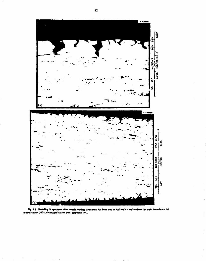
42
—* • -~0-'\*
d
o . -o
S " 5
(*) «aui *ZZ- 1
- ^ ^
* ^ « » ~ -
'-T —. .» '4 •»
o O-
8.
<C I (A Is*
o o-« §-(o
Fcj. 4.1. Ilartitoj N ipminun after mtsilr Inline, Specimen has been ail m half and cichcd in show ihc main boundaries, (a) mapMftcation 200x: lb) ntafcnilicafion 50x. Reduced I4"».

43
that contained 0.07 mule ''< UF, were then exposed to the (lowing gas mixture at a total pressure of I jtm. Preliminary trials with CO and CO; at I aim indicated that both were much too oxidizing to maintain aay measurable UF, concentration at 600* or 700*C. The oxygen pressure from reaction (I) can be easily calculated from standard equilibrium tabulations:' *
C0 = C * ^ O : . H I
A second reaction results in the conversion of UFj to UF 4 and U 0 2 : the UO : was identified as an end product in all cases:
4UF,<d)+2CO<g)
= 3UF 4(d) • U0 2 (c ) + 2C(c). (2)
Oxygen tugaciiies can be lowered by dilution with argon. Partial pressures of CO equal to 2 X 10"* aim w.ruid be necessary to achieve equilibrium (2>at 600*C for UFj and UF 4 concentrations of 6.7 X I0~* and 6.7 X I0" : mole %. respectively. Measurements were made at successively lower CO partial pressures until the practical experimental limit was reached at 1.5 X 10'* atm. In all cases, as predicted, reaction (2) proceeded to completion within the limits of detection.
These data indicate thst impurities such as oxide ion from UOj or oxygen from CO do not react with UCj to form uranium oxycarbides. The compound U 0 2 has no observable effect on the UFj-UF 4 equilibrium, but traces of CO oxidize UF, to UF 4 and U 0 2 . Therefore. U C v 0 J v phases are metasiable with respect to UOj and UCj at temperatures less than 700*C. and. as a result, the maximum tolerable oxide concentration in the fuel solution will be determined by the solubility Hniitof UO] orPajOj.
4.4 THE URANIUM TETRAFLUORID£ HYDROGEN EQUIUMMUM
IN MOLTEN FLUOR'DE SOLUTIONS
L. 0. Gilpairick L. Vf. Toth
Discrepancies exist between the equilibrium quotients measured for the reaction:
4UF,(d)*2C = 3UF 4 (d)+UC I |4 )
and those predicted from other sources. We have undertaken a reexamination of the equilibrium:
UF4(d) • ' / , » , = UF,(d)*HF. (5)
previously studied by Lung and Bbnkemruo'T because of the importance of reactions 141 and |5) to MSBR fuel-sali chemisiry.
In previous work.1 * the progress of the reaction and the concentrations of L'F, and UF« in solution were interred from the amount of HF evolved from the melt, so it was difficult to distinguish between side reactions and reaction I5». In addition, equilibrium could be approached only by reducing UF 4 . This procedure may be improved m several ways. In-situ spectrophotometric measurements of both UF, and L'F4 cunccntrai'ons as a function of time, temperature, and HF/Hj ratio are now possible. In addition, the recently available fluoride-sensitive electrodes aBow measurement of much 'ower HF concentrations. These improvements permit a wider range of temperatures to be explored, especially lower temperatures in the range of intcresl to the Molten-Salt Reactor Program. Another advantage of the new procedure is the possibiliiy of reversing the equilibrium by changes of temperature or gas composition so that equilibrium can be approached from either side while under constant monitoring and control.
Preparation of equipment and the assembly of a gas-handling and -analysis system for the study of reaction (5) are nearly complete. Pure H 2 is generated by an electrolysis palladium-diffuser unit. The hydrogen gas stream is saturated with HF (in low concentrations > from the dissociation KHF2 » KF • HF at a carefully controlled temperature. This three-phase system I excess KF is present) gives a ;cnirolled partial pressure of HF. 1* The blended gas stream is then passed over (or sparged through) the fluoride solution that contains UF, and UF 4 . winch is contained in a graphite cell. A newly designed pore-nickel spectral furnace encloses lue cell. Nickel construction allows for a cleaner system linn was previously possible, because of the more thorough removal of oxide species, which is possible by H 2 reduction prior to use. Gas mixtures entering and leaving the furnace are analyzed for (low rale, pressure, and HF content. Hydrogen fluoride determination is made by aqueous scrubbing of the gas stream and measuring the fluoride ion concentration with a specific-ion electrode.
16. JASAF Ttitrmomr>*mir TMes. 2d e4.. NSRDS-***)? K «i»7i ) . •':
17. r;. Lnnc mrf f . l MankemlMp. IheSnh*nnf Vnmm \ Tnfhmndr. ORNI.-TM-2oS3. Pan* I md II (November 19*9). |
I". I-, h. Wcstram. Jr.. awl K. F i lm. / Amrr. Otrm. Soc 4 7i. mo<m9). a

44
45 rOROUSELECTKOOC STUDIES
H. R. Bronstein F. A. Posey
Studies were continued on the development of porous and packed-bed electrode systems as continuous, on-Ine monitors of the concentrations of electroactive substances in MSER fuel salt. First priority n given to the design and testing of a device that could monitor, jnd perhaps dissolved bismuth from fuel salt, smce small concentrations of bismuth in iuel salt returning to the reactor from the processing plant could result in corrosion of ihe tbsteHoy N of which the reactor primary circuit would be constructed. Conimu-inf studtri in support of other programs haw; demonstrated the usefulness of porous and packed-bed electrodes for electroanalysb and for recovery of trace amounts of reducible inorganic pottuunts from various effluents and process streams."- 2*
During the previous report period, a prototype packed-bed electrode of gbssy-carbor spheres labout 100 u in diameter) was tested in a preliminary study by-use of the UCt-KCl eutectic system. 1 1 Results of linear-sweep voitammetric measurements, carried out in the presence of small quantities of mm salts and cadmium salts, showed that the cell, instrumentation, and auxiliary systems functioned successfully and demonstrated the inherent sensitivity of this method of analysis. However, the tests on the prototype cell showed the need to modify the experimental apparatus to facilitate the addition of known amounts o» various substances to the melt and to allow operation under vacuum or inert atmosphere over long periods of time.
Most of the effort during this report period has been devoted to the redesign of the experimental assembly, to the acquisition of more advanced and convenient instrumentation than that used previously, and to ;he construction and testing of the assembly prior to the resumption of experimental measurements. An overall view o. the new experimental assembly and the necessary control and measurement equipment b shown (Fig. 4.2). The ceil, located inside a test dumber, which is mounted on a portable lest stand «shown in the center of the picture), is inserted into a furnace that prrmits direct observation of the quart/ cell assembly durmr operation. The experimental assembly will permit establishing proper operating procedures for later studies on MSBR fuel salt, for which a metal cell assembly will be required. Attached to the lop of ihe lest chamber are various entry ports for insertion of the
pzci>ed-bed electrode assembly and lor addition of reagents, a thermocouple well, a counterelectrode. jnd an Ag/AgCI reference electrode, as well as pressure and/or vacuum linings for the cell and for the valve assemblies. At the left in Fig. 4.2 are shown cabinets that contain equipment for precise control of the temperature of the furnace and cell assembly. To the right of the test stand are rack-mounted instruments ft* carrying out the electrochemical measurements tpoten-tiostai with electronic auto-ranging coulometer. electrode-potential programmer, and electrometer). Abo shown at the right b a two-pen X-Y, .Yt recorder for simultaneous recording of current-potential and charge-potential curves for the pecked-bed electrode.
The newly designed packed-bed electrode is shown (Fig. 4.3). The packed bed of glassy-carbon spheres b supported on a porous quartz frit and b contained in a quartz sheath. Another porous quartz frit presses on the bed from above. A glassy-carbon rod penetrates the upper quartz frit to provide compaction of the oed and electrical contact with a long stainless steel rod that b insulated from the surrounding tantalum support tube. The electrode is dipped into the mdi so that the molten salt flows up through Ihe interior of the packed bed and out an overflow skrt. By thb means, a reproducible volume of melt can be obtained inside the packed-bed electrode.
Preliminary testing of the entire experimental assembly has been completed, and experimental measurements will be resumed immediately following preparation and loading of the sail mixture for the melt. Initially, work wnl be in LrCMCCl eutectic. since the behavior of a number of electroactive substances has already been eslabkJied for ihb medium, and thus the new ceU assembly can be conveniently checked out and calibrated. Results of experimental measurements on ihe bismuth system and on other ckclroadive substances will be presented in a subsequent report. Following successful testing iff the present cell assembly, a similar apparatus wiH be designed and constructed for use with molten fluoride melts.
19. K A. rmty ami A. A. Mfco. Kettofy mm* Amtytd of Timet Omimmmmtt Jtqgms Reman Ottnmrr 197J Semttmmtr /97#.ORNL NSF^ATC II (December 1*74).mm 14* SI.
20. H. R Nmnuem « 4 F. A. Pnaev. ( V m On Amm. /Tojr Htm. Mf 20. 1974. ORNL-407*. pp. 109 II.
21. H. R. •fMHtem JWJ K A. ttfey. MSH hvpmm Stmt-mum hogr Ktp Am Jl. 1974 ORNL-50ll.pp.49 i l .

45
1
1
i I !
•J
si a 1
«c i 5 *
i

46
PHOTO 0369-75
f**
F j . 4J. rmUihui t €Wthot$ M C f C I M t M F Nb
5. Coolanc-Salt Chemistry
S.I CHEMISTRY OF SODIUM FLUORORORATE
L.Maya
An unacceptable amount of the tritium 1731 Ci/day) produced in a 1000-MWle) MS8R could reach the steam system unless it is trapped by the coolant.1 Indications2 ate that a sodium ftuoroborate melt. NaBFV NaF (°0-8 mole Tr\. presently considered » one possible coolant in the MSBR. could sequester tritium. Wink done in the past with this coolant melt in the CSTF.* as well as in laboratory experiments.4 has shown the presence of at least two hydrogen-containing species, one acidic and the other NaBF jOII. In addition, one or more oxygen-containing species exist above the melt and also above the melt are additional volatile hydrogen-containing species thai are condensable at room temperature. These compounds constitute a potential sink for exchanging! and/or trapping the tritium. The presen; work is to identify these species, study their chemistry, and ascertain their ability to trap tritium. The approach chosen consisted of preparing and studying a number of ~-."tel compounds. The initial work, reported in the preceding report5. involved the synthesis and characterization of the following com-pound*: l l , O B F 4 . B F , 0 H j O . H B F . ( 6 l l l : . NaB!\»OH. Also reported was the synthesis of Na:BjF»0 and NajB.F.O,. Availability of these materials permitted an evaluation ^ the analytical tuoh available lo identify these compound* in actual systems.
1. «;. T. HJJI. Scvi. I.I.I M ihnrcpHi 2. *'. R. (kimcv i. <;. BnMmai. A. S. Mryrr. jNd 1. M.
fUk. "Vwtl tmi ('••ntmi ("bow Mry.~ chap. 5. Ihr Dctfinpmrni Sana nf Vnittr Ml 9rcr4rr Rfrttwt. ORM -4X12 (AneaM
V A. S. Mr*« 4nd I. M. Ualt. -inaf litem Orr IIMH ftnff. Rrp Off* JO. It'}. ORNI -»•>«». pp. > 30
4. I>. I. MNMNIC. HSR trnfnm 'AwilMr Repnrt /«» tufusi If 7:. HSR- 7_*-.W fmurnd camtmmctlinnl. pp. 14 15.
V I. Miyj. HSR Ftnfrtm Srmmnmt fr**r. Rrp. '"f -*'. I-'V. ()RM -.Vlll.p. 25.
During this report period the system HBO2-H3OBF4-H : 0 was characterized to help explain the behavior and composition of the volatile fractions condensed from fluoroborate melts. The compounds H3OBF4. HBF:tOH>2. and BF,-2H>0. which are constituent; of this system, were examined using nuclear magnetic resonance iNMR) spectroscopy. The protons in all these compounds undergo exchange among the hydronium ions, the undissociated acid, ant the anion, furthermore, there is also pi 01 on exchange in mixtures of these compounds. The fluorine NMR showed that the fluorine atoms are equivalent in these compounds, as would be expected, and that there is fluorine exchange in mixtures of these compounds. The NMR of these compounds is thus of limited value as an analytical tool in view of the exchange processes taking place: no specific signal could be assigned with -urrUinty U a particular species.
Ternary diagrams for the system HBO : -H,0BF 4 H : 0 at 25 and M) f hsve been jonstrue'ed 10 aid in characterization of these compounds in ihc pure stale or as mixtures. The diagram for the system at 25°f I Fig. 5.1) shows a large area of composiiitms having an equilibrium solid phase. The main features ai 60oC are the same as ihose observed ai 25*f. The s«tlid phase is brri« acid for compositions of relatively high water content and meiabonc acid for compositions of low water content: there is also a limited region which contains both solid phases. The composition of volatile fractions from fluoroborate melt, expressed in terms ot molecular species, can be found from the fluorine and boron chemical analysis of the mixture. The fluorine c<mcen-fration is expressed as HjOBF*. and the boron content, after subtraction of the am«mnt present in HjOBF.,. is expressed as HBO., thus fixing a composition in the diagram. This is illustrated for an actual condensate collected in the Coolant-Salt Technology Facility. The analysis was 22.t> millimole* of F per gram and *'..» rmllimotc* of B per gram.'1 This gives a composition of «) . : wt -. H,OBF4 and \*>A wt r\ l!BO :. the difference being water. F .pressing this in terms of the Mablc
47

48
F * 5.1. Tenwry H « *i^mt far Ae jysatM HM>.-HtMF.4i.O;4 25*C.
molecular spe ies for this region of the phase diagram gives the compuition: 79^ BF,-2HiO. 12* H,BO,. and^HjO.
The ternary diagram is useful disc in predicting the relative stabilities of the molecular species. It has been found that HBF2(OHh «s a metastaMe species at 25T that should disproportionate according to:
3HBF1(OH>2 - HBO, + 2(BF, -2H,0|. (I >
This prediction was experimentally instantiated. The BFj-2H20 has z relatively higji free energy of formation, which accounts for the fac! that boric acid is dehydrated at room temperature according to:
BF,+2i: ,BO,-HBO : + BF,-2HjO. (2)
The NMR studies and the work done in preparing the phase diagrams indicate that the molecular species of the system can form stable solutions under certain conditions and interchange easily on addition of HF. BF.t. or HjO: therefore the volatile fractions formed from the fluoroborate melt are most likely a mixture of compounds rather than a single compound. Also, this means that isotopic equilicrium should be readily attained between prntium. deuterium, and or tritium, which suggests that isotopic exchange should be a viable method of tritium trapping in the MSBR.
Determination of the oxide and hydroxide species present in the melt at low concentrations is a much more difficult task since the quantity of (luoroborate will interfere. The compound NaBFjOH can he determined* by the OH absorption in the infrared region.
6. A. 5. Meyer « »'•• "Infr-trcd Spcvfrai Sfndie* of M«lf<n and Soiirf NjMVNaf-." Jm* <*«" I**. Annu. A«rr Rrp Srpt J< .X72.0RXI.-4II.H. p. 24.
but the bands for oxide species are not specific and appear as broad signals in the region from 700 to 1400 cm"1, where there is considerable overlap of the sodium fluoroborate bands. X-fny powder diffraction arulysis b of limited value since it cannot distinguish less than about 5 mole % of foreign species in fluoro-borate. NMR is also of limited use unless the species are in solution. Thus, the development of separation techniques or the finding of more sensitive spectroscopic means of detection are required. Dimethyl sulfoxide (DMSO) has been examined in an initial attempt to work out separation procedures since it dissolves up to 20 wt % NaBF4 at room temperature without decomposition. The solubility of Na.BjF^O, in this solvent is very low. less than 0.5 mg of B per milliliter-, thus. DMSO was used to separate these »wo compounds. On the other hand. DMSO reacts with NaBFjOH and Na;BjF*0. producing acidity and BF4 ~ ions.
The compounds Na2B2FtO and NajB,F»Oj. potential oxygen-containing species in te melt, were examined by differential thermal analysis and thermogravi-metric analysis. Both are thermally upstable and do not show a sharp melting point: instead, they form glasses, and a crystalline phase segregates that is composed of NaF and NaBF4 in the case of Na I B I F 4 0 and cf NaF in the case of NajBjF,0,. This finding would tend to eliminate these compounds as possible oxygen-containing species in the mell. however, this is not certain since NsBFjOH is also unstable as a pure compound but has limited stability in the melt. Experiments were made in urder :« find alternate stable compounds in the system NaF-NaBF4-BiOj. of which both NaiBjFfcO and Na.,BjF»Oj are components. Five mixtures in the system were examined:
Mnfcmbr ratio
MiMarc NaF NalU>. B , 0 , 1 2 1 1 2 1 1 1 J I 2 I 4 2 2 1 5 0 2 I
Fach mixture was melted in a platinum container under a nitrogen stream at either 450 or 550"C. There was no significant weight loss except for mixture 5. which showed a weight loss corresponding to the volatilization of one mole of BFj. In addition to ihev mixtures. \ J , B , F » O I . \3jB : F»0. and a mixture composed of NaBF4 and NaBO: t2:l ratio) were also examined. All these mixtures fr.nicd gla»s«.s: however, a crystalline ph;« could He separated from all except the 1:1:1 mixture. Chemical analysis indicated, and later x-ray

49
diffraction analysis confirmed, that the identity and approximate quantity of the crystalline phase corresponded to the component (or components) in excess of the ratio 1:1:1. Chemical analysis abo showed that boric oxide or the inelaborate was converted into a compound containing B-F bonds.
The following conclusions can be derived from these experiments: (1) Simple B O-containing compounds, such as BjO) or BOz~. can be drcounted as the oxygen-containing species in molten fluoroborate: any B-O species up to a certain concentration wil contain fluorine as well; 12) fluoroborate melts can contain relatively large amounts of oxide species without forming a separate solid phase: and (3) there are indications that a compound containing NaF. NaBF 4. and BjO, in a mrtar ratio of 1:1:1 is especially stable. This would correspond to a compound with the empirical formula Na xB)F)Oj- Further spectroscopic evidence for this will be sought.
The compound NaBFjOO was prepared by the reaction:
NaF • DBF2(OD»i - NaBF,OD • DjO
in an 88.6^ isotopic purity, for the development of an infrared method of analysis by the Analytical Chemistry Division.
Samples of salt and condensate obtained during a recent run7 of the Coolant-Salt Technology Facility were prepared for analysis. The tritium content of these materials was found to be J.35 X I0 J jiCi g for the salt. which pve* a tritium concentration factor of 7.o X 10 s
in the condensate relative to the fluoroborate melt. These values are similar to those previously reported.3
confirming that fluoroborate metis can contain tritium and that the condensate provides a means to concentrate and eliminate the tritium. The mechanism for the process is still unknown.
5.2 CORROSION OF STRUCTURAL ALLOYS BY FLUOROBORATES
S. Cantor B. F. Ihich
5.2.1 Tiwmwdy tamma of Crtltl) in Ftworoborate
When oxidants «.$.. 0 2 . l l 2 0 . Ni :*)are introduced into molten NaBF4-NaF in contact with alloys c«»n-lainipg chromium, a sparsely soluble green sail. Na»rrF». is formed. Other complex salts might also have been expected to form since the NaF-CrF., phase diagram* shows the existence of Naj("rF».Naj('rjF| 4.
and NaCrF4. An experiment was designed to obtain the free energy of formation (AG?) of Na,CrF4 by measuring the equilibrium BF, pressure from the reaction
CrF,(c) + 3NaBF«(d.«-N.I)
= Na,CrF»(c)+3BFJ($). ( I )
However, it was found that Na,Cr,F, 4 abo forms when O F , and molten NaBF4 interact: thus, it was not possible to measure AGf of Na,CrF4 by reaction (I). but the relative stabilities of Na,CrF 4 and Na 5 Cr,F I 4
could be determined from the equilibrium
, ANa,Cr,F l 4 (c)*%NaBF 4 (d .«5 4 I)
= Na,CrF 4(c>*%BF,(g>. C )
for which the equilibrium constant is
* > ' i F , V (3)
where Ftf a the equilibrium pressure. Measurements cf BF) pressures taken over mixtures
of differing proportions of cystaliine \ a 5 C r , F 1 4 and Na,CrF4 in molten N J B F 4 yielded the same pressure date (Fig. 5.2) in the temperature range 408 to 5<*2*C.
7. A. N. Smilh. prrwmjl >i>mmiMicjlN<n. %. A. IVK"/;*. Cnmpl. nrmi. 1*HT. 4l*< !«»*.<»».
125 US ioVrrK)
Fig. 5J. IF, pnimm fmm rke rcaclnn: N»«C»,F, ,(s> • *.; NatF. id) * Ma.CrF.(«» • \ i f , t|).

so
A least-squares fit of the data is given by: o-'*)? <68
*>/»B F jlalm)=«M »IO±00»»> - ^ — _ _ . (4)
The dbpersittn values are standard deviations from least-squares solutions of these constants.
The free energy change for reaction (2) is given by the expression
at T = 800°K. iCr = 0.S2 kcal. The enthalpy change for (2) is
.1//°-- 4 / , « J /nF B F j /< /7" , = 24.6kcal. (6)
From the thermodynamic daie ' - 1 0 " ' 2 for the equilibrium
N3Rc^BF Jtg)=NaBF 4(0 (7)
it can be shown that, at 800°K. the difference between the molar free energies of formation of BFj(g) and NaBF4l/)isl22kcal:
This is combined with <XCi° at S00°K for reaction (2) to obtain a free energy difference between the two c-nn-plexes:
• * C ^ a , O F . W ^ r , , * , . ' 163 kcal. (<»
TTiis difference permits (he calculation of (he difference in ZWV° between the following two reactions of complex formation:
3NaF!c> + CrF3<c>=3NaF<-rF3k>. (10)
% NaF(c) • CrF,(c> = % NaF <" rF,(c>. (II)
At 800°K. Xfi 10) MftII > = 6.3 kcal. In other words, a mole of C'rFj is more siable by 6.3 kcal in
9. JASAF Thermodynamic Tables. 2d id.. ' "RDS-NB5J7 <I97I>.
10. P. (Jnwv ('. (layman, and H. A. Jnel. Tram. Faraday Soe. 64. }I7(I%H).
11. A. S. Dworktn jnd M A. Brcdig. / (hem. hnf. Data 15. 505(1970).
12. S. Cantor, derived fr«>m data wmmarized in ORNI.-TM-2JI6. p. 34<I%8).
NajCrF* than in Na 5 CrjF| 4 . This greater stability explains why Gllll) coercion products precipitate from tluoroborate coolant as NajCrF* rather than as Na 5 Cr,F I 4 .
S.2.2 Metal Boride FonntiM
Thermochemical data for the borides of Fe. Cr. Ni. Ti. and Mo are sparse and often unreliable. Thus, it is difficult to accurately predict the extent to which reactions such as
2NaFld> + NaBF4(d) • \x * I )Cr(c)
= Na,CrFjc) + CrrB4c) 02)
may occur in ai. MSBR coolant loop. The free energy of thb reaction is probabl" negative: thus, molten NaBF4-NaF in contact with chromium or a chromiun--ontaining alloy is likely to form borides. To test boride deposition ai.-l penetration of structural alloys, an apparatus has been assembled in which metal specimens are equilibrated for varying periods of time in molten NaBF4 NJF (92-8 mole %) at 640°C. specimens and salt are kept under a protective argon atmosphere. Specimens renvved from the salt are first washed in boiling water for several minutes to dissolve salt adhering to metal surfaces: the metal is then analyzed for boron by spark-source mass spectrometry (SSMS) and by ion microprobe.
Spark-source mass spectrometry showed increased surface boron concentrations for specimens of Hastelloy N, modified Hastelloy N containing 27<- Ti. and Inconel 600 that were equilibrated with molten NaBF4-NaF for periods up to 72 days. Typical analysis showed about 100 ppm B for Hastelloy specimens and up to 1500 ppm B in Inconel 600. compared with unreached controls in which B contents ranged from 10 to 30 ppm. Ion microprobe mass analyses were made on two metal samples: Inconel 600, in which SSMS showed 1500 ppm B. and Hastelloy N. 80 ppm B. Boron was found distributed in small particles on the surface of the Incond 600 sample, but the ion rricro-probe analysis could not quantify the amount. Chromium was significantly depleted from the surface. Boron was also observed on the Hastelloy surface: removal of part o( the surface showed only a much lesser residual concentration « I 0 0 ppm) of B, and (his was not present in discrete particles. In contrast with the Inconel 600 specimen, the Hasted y specimen did not show a surface depletion of chromium when 'the simple was observed through a depth of about I jim.

51
$.2.3 Co i of Nickel NiF,(c)*NaBF«(/) = NaNiF,U) + BF,(*) U6)
In heating crystalline NaF and CrFj to 890°C in nickel capsuk>. finely divided nickel metal panicles were found in the cooled salt, which indicates that the nickel is evidently attacked. An explanation of this result is that the reaction
NaRi)*2CrF,(c)+Ni(c>
= NaNiF,(c)+2CrF2(c> (13)
occurs, proceeding to the right at high temperature and reversing at low temperatu'es. Sturm'3 reported that mixtures of CrF, and CrF 2, when heated in nickel, underwent the reaction
2CrF, • N i = NiF 2 *2CrF 1 . C.4)
This proceeded to the right at 600 to I000°C but was reversed upon cooling, although the JG° values of reactions (13) and ( i4) seem to be positive. Possibly these reactions serve as mechanisms for mass transfer of nickel. That nickel undergoes mass transfer in an Inconel pump loop 1 4 can be rationalized by a reaction analogous to (16) and (17).
2CrFj(d)+NHInconel)
N a B F , N & F N i r 3 ( d ) . 2 C r F ; ( d ) . (15)
Indirect evidence for reaction <ISi comes from a study of Na,CrF A solubility in NaBF4-NaF. Barton" reported that two samples taken at temperatures close to 700°C gave values of 300 and 390 ppm nickel, possibly indicating corrosion ot the nickel container.
By combining the data measured16 for the equilibrium
13. B. J. Sturm. Inorg. Chem. 1.665 (1965). 14. A. N. Smith, I'.xpehencc with Sodium Fluorohonle Cir
culation in an MSREScal* Facility. ORNL-TM-3344 (September 1972). pp. 103 5.
15. C. J. Barton./ lnor% Sud. Oirm. 33. 1946 (1971).
with caiorimetric17'1* (NaF. NiF 2) and estimated (NaNiFj) enthalpies, the thermodynamics of the reaction
NaHc)* NiFi(c) = NaNiF,(c> (17)
was obtained- At 298.15*K. the calculated results for reaction (17) ?..e: HJf = 0.7 ± 1.4 kcal -mole. AS° = 4.9 cat mok"' °K~ I- The uncertainty in AW" is that assigned1 * to the formation free energy o( NaNiFj.
An interesting aspect of reaction (17) is that A/r" is nearly zero. In essence, the stability of the complex (NaNiFj) depends on its entropy, which is greater than the entropy of the component salts. The thermodynamics of crystalline NaFeFj is likely to be similar. An analogous situation exists for MgF2- For the reaction
NaRc) + MgFj(c) = NaMgF,(c). (6)
£ / /? , , = 0.1 ± 0.5 kcal'mole, the data having been ob.aincd by aqueous solution calorimelry "
The stability of Na3CrF* (the green salt thai is the characteristic corrosion product of any chromium-containing alloy found in eutectk NaBF4-NaF) is certain to be much greater. For the reaction
NaRc) + V3CrF,(c)= VjNaiCrF^lc). (7)
A/£*s is probably - 6 kcal (per mole of NaF): this enthalpy change is estimated from the analogous alumi num reaction.
16. C- F.. Bamberger. B. f. Hitch, and C. F. Baes. / Inorx Sucl. Chem. 36.543 (1974).
17. A.C. Maclcou./ Chem. Soc. Faraday I 2026(1973). 18. I. S. Binford and T. H. Hctwrl. / Chem. Thermo
dynamics 2.407 (1970). 19. A. I inch. P. J. Gardner, and C. I. Slcadman. Can. J.
Oiem. 46. 3447(1968).

6. Development and Evaluation of Analytical Methods A. S. Meyer
6.1 M-UNE ANALYSIS OF MOLTEN MSB* FUEL
R. F.Apple B R . Clark J. M. Dale D.L. Manning A.S.Meyer
Much of the program effort during this report period was spent in doing in-line analyses in corrosion test loops. Presently the U**/U** concentration ratio is being measured in one forced-convection toop(FCL-2b) and two thermal-convection loops (NCL-21 and NCL-23). During the coming year this effort will expand to include in-line analyses in as many as a dozen circulating-salt faci'ities. To perform these measurements, which must N. carried out at widely spared locations, two additional volt .nmeters have been fabricated and are now being checked out prior to installation. Voitammetric data generated for the determination of U**/U>* should also be useful fot later estimation of relative changes in corrosion-product ion concentrations. The chromous-ibn reduction wave and anodic stripping wave may be suitable for making semiquantitative measurements of the chromous-ion concentrations.
A relatively kng record of the 11*711** ratio was obtained during the first six months of operation of FCL-2b. This forced-convection loop initially conta:ned an experimental fuel of LiF-BeFj ThF« (68-20-1-' mole %) with bout 1.4 wt % I , , U . This facility is now operating with a referei.ee fuel composition of 72-16-12 mole %: tlectroanalytical measurements are in progress.
Initial attempts to obtain clectioanarytical data on the circulating salt were complicated by various convec-tive modes »>f mass transfer to the electrode surface, namely, vibrations from the pump motor and thermal gradients near the electrode. Reasonably good data were obtained when the circulation was temporarily interrupted for the measurements. In the near future, an electrode assembly will be installed with special features to eliminate or minimize the problems encoun
tered in obtaining reliable measurements during circulation of the melt.
Many ekciroanarytical measurements were made throughout the operating period of April 18 to October 24. 1974. These measurements have provided our first experience in the voitammetric analysis of thorium-bearing fuels, and the data provide a basis for comparison with dectroonalytical measurements being made in the reference fuel salt. UF-DeF :-ThF4 (72-16-12 mole %), which has a significantly higher "free fluoride" concentration.
As repot .ed earlier,1 qualitative differences are evident between electrochemical behavior in this fuel solvent and in the more familiar MSRE compositions (LiF-BcFj-ZrF*). One of the more significant differences was an apparent improvement in the resolution between the chromium and uranium reduction waves. Because of the absence of zirconium in the thorium-bearing fuel, a higher cathodk limit is observed, and the reduction wave for U 3* • 3e~ -*U° can be observed if the potential is scanned a few hundred millivolts beyond the U** reduction wave.
Under conditions of minimized convection and reasonably fast scan rates (0.1 to 0.5 V/sec). voltam-mograms are obtained which exhibit a shape closely resembling the theoretical shape for the reverstW* U4* + e~ ^ U > reduction. A typical wave of this sort has been illustrated previously.' Not all the waves used for the calculation of U*7U>* ratios were clcse to ideal, and hence many were not easily rmeroretable. The method used for the calculation of the U 4 * / U > ratio has been reported previously.2 Two points must be measured to use this method: ( I ) the rest potential of the high-impedance iridium quasi-reference electrode and (2) the
1. A. S. Meyer et al.. Anal. Chem. Dh>. Annu. Progr. Rep. Sept. JO. /97f,ORNL-50Q6.p. 25.
2. A. S. Mey-r et al., MSR Program Semitnrw. Progr. Rep. Fth. 28. 1969. ORNL-096. p. 200.
52

*"a^^'^s»*t^f«rl^;_, .
53
halt-wave potential of the U** - U** couple. The fust point is ihe zero-current potential between two iridium electrodes, and the second point (half-wave potential) is extracted from the uranium reduction wave generated with linear-sweep volianunetry.
The preosion of dus method appears to be broiled by the assignment of half-wave potentials from the raw data. In a potential-sweep experiment, the theoretical half-wave potential is the point on the cum which occurs at 85.2% of the peak height.1 This is true only for reversible systems and does not include contributions to Ihe current from sources other than the reduction or oxidation of the couple in question. In actuality, curves are seldom ideal because charging currents and extraneous Faradak currents are included in the total current responses. A more reliable method for obtaining half-wave potentials from nomdeal curves is to choose the potentials at the midpoint between the peak potentials of the camodk and anodic peaks. Such a treatment makes the reasonable assumption that the shift in the peak potentials occurs to the sam* extent (but in opposite directions) for both the cathodk and the anodic waves. In the ideal case, the half-wave potential is midway between the peak potentials. In the treatment of these data, the half-wave potentials were assigned using the two methods outlined above. In addition, a theoretical point was chosen about SO mV more negative than the derivative-wave peak potential. Half-wave potentials for each curve were computed by these three methods: the bisection method gave the more
3. R. S. Nicholson a.M I. Slum. ArmL Chtm. 36. 706 (1964).
consistent results. Whenever die curves approached ideality, a l three methods yielded potentials in good agreement with each other (about 5 mV).
Data obtained during the six-month operation with the experimental fuel meii have been evaluated for U**7 U** ratios, and the calculated ratios are recorded as a function of time (Rg. 6.1). The data in this figure can best be considered in four sections: ( I ) die initial period of 40 to SO days during which attempts were made to make measurements in circulating melts (there were frequent variations m loop operation interspersed with maintenance shutdowns). (2) a period of about three weeks during which the ratio was deliberately adjusted by the addition of beryllium ratal, (3) an interval of essentially steady-state operation Cv>50 days), and (4) a terminal period during which additions of nkkd fluoride were made to reoxidize the fuel.
The initial period is characterized by widely scattered data, which can be interpreted only as general trends. In view of the quality of many of the voltammograms recorded in the interval, this scatter must in large part be attributed to the analytical method. Initially the fuel was quite oxidizing (U*7U* ratio about 10 s. perhaps the upper limit of the method): the ratio was rapidly reduced to about 10* by reactions with the loop metals, principally chromium. On continued operation the ratio underwent a gradual decrease, with a concurrent increase in the height of the observed chromium wave. When the ratio had decreased to about 3000 and the chromium wave had r-'come quite pronounced, incremental beryllium additions began.
These additions were made using beryllium foil specimens of sequentially increasing weight calculated :o
2 3
10* OftNL-DWG 75 -»309 10* : ! ' i ' r • i ! ' \ ' ! ' 1 :
» t •• •
Beryllium Additions
•
'»
— I0 4
» t •• • - 7 9»ng •
'»
—
103
: -33.7
1,* r-33.0 f t ' -33.1
• *.
"'1 I • • _ •
102
* • » r 6 7 5 • ' ••
' 975m9 1450 •1
1600; Nidut Ffcionge Additions *
• A , I ! . 1 . i 1 -20 4 0 60 8 0 100 120
ELAPSEl TIME, days 140 160 180
Ft- *•>• U**/U" ratio* mtwHim forctd owttctton loop FCL-Jb.

54
yield an laumbigMOus decrease H I the ratio. The speci-mem were crimped in a loop of platan—-tfcodinm wire which was welded to a rod that could be iaserted through a Teflon bushing on ihe samphag port. A* elYori was wide lo avoid shorting the support rod to the apparatus, so that contact of toe s p e c i f with die fuel could be delected cketricaly-. however, in most cases the support rod was inadvertently skoried lo the loop either durmg insertioB o» through vibration when circulation was started. The berytnan specaneas were inserted I to 2 m. below the quiescent fuel surface. ctrcuLuwn was resumed, and the progress of the reduction was foHowed. qualitatively, during the next lew hours by voltammetric measurements. Although the effects of stirring and vibration mentioned earner precluded measurements of the uranium wave, shifts m the position of the distinct two-electron chromatin wave could be detected.
Poteniiometric measurements of the melt using the reference electrode vs the berylium support rod and vs iK- loop structure were made for some of the reduction steps. It was jbserved that when the beryllium was shorted to the loop, reduction took place smoothly and rapidly to ostensible completion in 2 to 4 hr. On one occasion when the support rod was electrically isolated from the structure, reduction slowed to an undetectable rale but accelerated when the rod was deliberately shorted. An electrically isolated beryllium specimen assumed a potential > l V negative to the melt. When the specimen was connected lo Ihe loop structure, the potential decreased to a value less than 100 rr>V. so that the potential of the fuel was positive lo both the walls of the loop and the beryllium specimen. Therefore, it is evident thai the bulk of the reacti-m occurred by electrolytic reduction of U 4 * at the inner walls of the loop rather than by direct chemical reaction at the beryllium, which would be rate-limited by transport of IT** lo the small surface of ihe metal specimen. Although no further reduction could b* detected after 4 hr. the support wire was left in r ' j . : for at least 24 hr lo ensure quantitative reaction with residual beryllium or its reduction products.
Die results of beryllium additions are shown in Fig. 6.2. an enlargement of a section of Fig. 6 .1 . The overall curve in this region resembles a titration curve, and indeed the reduction experiments represent an uncommon polenliometric titration. An examination of detailed response lo addition reveals a reasonably consistent pallern (after the third reductanl addition) of an immediate decrease in ratio (reduction of fuel) followed by a slow increase in the ratio toward recovery of the initial value. With some license taken in connecting
sparse data points, ihe tendency toward recovery can be interpreted as approaching a aew steady-slate value withai a period of several days. Regrettably, ihe lane between additions was act enough lo achieve steady-stale ratios, aor was rhe frequency or precision of the ntasaicanats sutlficieat lo perant •aaihemaiical analysis of the observed recovery regions. The recovery can be readily explained by the oxidation of U** by C r 2 \ bat the slow nature of the recovery may reflect hetero-
rtioas awulviui zither the loop watts or • metal ia the fad.
Rgare 6 3 ilusirales the yield of U 3 * from individual redaction steps. For each redaction the unshaded bar represents the equivalents of berytwaa added and the shaded bar represents the total equivalents of U 3 * produced during the immediate rapid redaction (cafcubied
to 5 IMS TV4»t*
BERTLLIUM A00ITKMS
10' J_ 60
ELAPSED TIME (dors) 00
Fig. ft.2. Effect of htfylHwm MMMIMS OH circulating MSM rari.

55
H)
IS " • U'MONCO -•
5 " - B -
•i %
m - • -
s • -0 n fLlt - f l
F*.*-*- VaHnTC'
from the increments in ratio and the total equivalents of uranium in the loop). Low yields in the carry reductions were expected because at >wg£ ratios the beryllium is largely consumed by strong oxidants such as Te 2*. For the intermediate additions, stoichiometric reduction was obtained within the precision of this method. The low yield in the last reduction ran be attributed to consuciplHKi of beryllium by chromous ions. A decrease in ionic chromium concentralior was evident from voliammugrams but has not yet been quantified. The overall yield of the additions was H5*>. Thus, the results of the reduction experiments show thai the present method for determining the U^IV* ra'io is also reliable in thorium-bearing breeder fuels and needs only to be optimized for maximum sensitivity and precision.
During the third period, of less eventful operation, the data are more consistent, with an estimated overall precision of measurement of about 10%. This value may not fairly represent the reproducibility of the analytical measurements, however, because some of the variations may reflect char%. s in ratio with minor changes in loop operating conditions, for example, temperature. ST operations, etc. In earlier measurements, made in a thermal-convection loop under more favorable conui-liom. a precision of about 2 ^ was obtained.4 A final plotting of the most probable ratio in the fuel and final evaluation of the measurement will be delayed until a comparison of in-line analytical data with the operating history of the loop can be made.
During the fourth period of operation, three NiF> additions were made. An expected oxidation of the fuel (increase in U*7U ' * ratio) occurred, folowed by a relatively slow reduction (Fig. 6.1). Again it may be necesary to evoke heterogeneous reactions to explain this slow recovery. It is doubtful that quantitative interpretations can be node for these additions, because the NiF 2 reagent was so finery subdivided that it is not possible to be sure that a l of it mixed or reacted quantitatively with fuel.
We arc now attempting to interpret the data from these measurements for chromnun concentrations. These concentrations vriM be used to lest electron tnl-mra during reco-ery periods after the additions of reductants and oxidants (eg. , check the agreement with stoKhiometry of the reaction 2 U * • Cr 1 * ; • 2U** • Cr° during these periods). I.i addition, an estimate of the equilibrium quotient will be made for the above reaction, and the data wul be examined for evidence of C r 2 0 , formation* in oxidizing melts. Quantitative interpretation of the chromium data is compwcaicd by interference from the adjacent uranium wave, variation in the area of the working electrode, low tolerance of stripping methods to disturbances in the melt, and absence of basic experimental data such as diffusion coefficients in the thorium-bearing breeder fuets.
The loop FCL-2b has been recharged widi fuel of the reference composition LiF-BeF2-ThF« (72-16-12 mole %) vs (68-20-12 mole T ) used in the original study. At this lime, no effort have been made to adjust the redox condition of the fuel, and voitammetric measurements arc being made on a weekly basis. Immediately after the loop was filled on February 1C. ihe furl was oxidizing (taiio 7 X I 0 2 ) . however, the V**IV'' ratio has diminished to about 2 X IQr. presumably by reaction with chromium in the walls of the loop or in the specimens. Measurements arc also being made on the fuel in two thermal-convection loops. NCI-21 and NCL-23. In NCL-21. which was fabricated from Hastdloy N and had been operated with MSRE fuel sail previously, there has been little indication of reaction. The U 4 7 U V
ratio was about 200 initially and decreased during the fin' month lo about 28. where it appeared to stabilize. About a week after Inconel specimens were inserted, a second trend of reduction was evident, and the ratio is now apprudching 10. This melt is now one of Ihe most reducing so far. and il may well be approaching ihe applicable limit of this voliammeiric method.
4. J. M. Date and A. S. Meyer. MSR Pnifrsm Srmiannu Progr. Rep. Aug. J1.1971.0WNL-O2S. p. 69 5. C. V. fees. Jr../ Xitel Mtltr. 51. 155 M974).

»
k 2 C X K T R O A N ^ Y T K A L S T U M B O F MSMUTU m MOLTEN UF-BeF: i F 4
G. Hamantov* D. L
Voltammcttic studies of bianMh in molten LiF-BtF,-ZrF« (65.6-29.4-5J0 mote %) were contimKd to asceitatn the lower limits of detection by bnear-scan voitammetry and anodic stripping techniques. This study is directed toward determining the feasibility of n o i ^ m-line measurements of traces of bismuth in the rctnrn stream from processing systems. As indicated prenoud/. 7 bismuth is slowty lost from the melt, al least in part, by vobtiuzaikm. presumably as MFj.
Became nickel is an anticipated interference, the effect of nickel on the bismuth voltammograms was determined whne enough bismuth (approximately 5 mmwnniar) remained to produce welt-defined curves. Nickel as NiF ? was aHded to give an Ni2* concentration of 15 malimolar. Voiummograms were recorded at gold, indium, and gbssy carbon electrodes. At the three electrodes, the reduction of bismuth occurs first at approximately 0.05 V. followed by nickel at about
0.25 V m quasi-reference electrode (ORE). Thus, the peak potentials are separated by about 200 mV. which, although not ideal, warrants investigation al tower concentration kick. In general, the best resolution, definition, and reproducibility are obtained al the gold electrode. However, or reverse scans, a single stripping peak is observed at gold, which may correspond lo the oxidation of a Bi-Ni alloy.
Votiammograms showing the reduction of bismuth in the presence of nickel at an iridium electrode are shown in Fig- 6.4. For the upper curve, the melt contained approximately 500 ppm Bi** and 240 ppm Ni2*. The nickel wave is poorly defined: however. Iwo clearly separated stripping peaks were obtained on reverse scans. The first peak could correspond lo the oxidation of Ni or possibly Ni-Bi alloy, and the second peak corresponds lo stripping rmmut1) from the electrode. When the scati is started at an initial potential of about +0.4 V vs Ir QRE. a small prew*w is seen, which, although not yet completely understood, is believed lo result from the adsorption of bismuth al ihe electrode surface. The second voltammogram corresponds to about 10 ppm Bi** and 240 ppm Ni1*. The bismuth reduction wave has practically disappeared, and only one stripping peak
(largely due to nickel) is present. The prewave. which is shown on an expanded scale in the lower curve, did not change significantly.
The slow toss of bismuth from the melt a! 600"C was followed voltammethcaHy. the concentration decreased from approximately 400 to about 7 ppm in 40 days. Tms is about the lowest concentration that can be measured by direct bnear-scan voitammetry. Anodic stripping techniques were used for measurements al tower concentrations. By plating bismuth under con-troued conditions of time, potential, etc.. onto glassy carbon at a potential sufficiently cathodk to reduce Bsflllp but not Nu.ll). and then scanning the potential anodkaly. the bismuth is stripped from the electrode, and the peak height of the anodic stripping curve is a
M-13554
3 U
-ICapm Bi
6. ComaiMm. Prnfwor of Chemrtlry. Vnmni'.y i»f Tcimev MC. Knoivrtlc. Tcnn.
7. A. S. Meyer cl al.. Anal. Chzm. Dir Annu. Ptnfr. Rep. Stpl. M /9W.ORNI..5fl06.p. 27.
£ ( V r» Ir QRE )
Fig. 6.4. Vodammograns for the reduction of bwnutMIII) and nkkeXII) at an indium electrode.
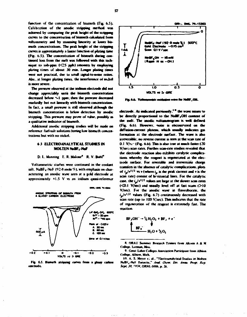
57
function of the concentration off bissath (Fig. 6J>. Calibration of the anodic stripping method was achieved by comparing the peak height of the sirippmg curves to the concentration of bismuth catenated from voUammetry and by assuming linearity at lower bismuth concentrations. The peak height of the stripping curves is approximately a linear function of plating time (Fig. 6.S). The concentration of bisnwth during continued loss from the melt was folowed with dus technique to sub-ppm (<25 ppb) amounts by employing pfafing times of about 30 mm. Longer poring times were not practical, due to small signatao-noise ratios. Abe. at longer plating times, the interference of mdud is more severe.
The prcwave observed at the iridium electrode did not change appreciably unii die bismuth concentration decreased below M ppov. then the prewave decreased markedly but not hncjiuy with bismuth concentration. In fact, a small prewave B still observed although the bismuth concentration is below detection by anodic stripping. This prevrave may prove of value, possibly as a qualitative indicator of bismuth.
Additional anodic stripping studies will be made on reference fuel-salt solutions having low bismuth concentrations but with no nickel.
6 3 ELECTROANALYTICALSrUOvESIN MOLTEN NȤF4-NaF
D. L. Manning E. R. Makme" R.V.Buhl*
Voltammetric studies were continued in the coolant salt. NaBF«-NaF (92-8 mole %). with emphasis on characterizing an anodic wave seen at a gold electrode at approximately +1.5 V vs an iridium quasi-reference
<wn.-emi *• ISM
VOLTS r» If 0MC
Fig. 6.5. Bomarh stripping cwrves from a fhwy carbon electrode.
on»-_ out. 7«~t33S3 r T ' T • 1
T /
• - '
T / sotrc T / I CaM Ofctinas - a e o n * ' " * / / Sow atv/sne
lil U n a H M - O H )
Tv7 • « • •
VOLTS* banc
electrode. As indicated previously.1* the wave seems »o be directly proportional to the NaBFjOH conieat of the mdt. The anodic voliamnMgraai is wcl defined (Fig. 6.6). However. *ioise is encoun'ered on the dilTuRon-caneni plateau, which wswafly indicales gas formation at the electrode surface. The wave is also irreversible, no reverse current is seen at the scan rate of 0.1 V/«<- (Fig. 6.6). This is also true at much faster (20 V/seo scan rates. Further scan-rale studies revealed that the electrode reaction also exhibits catalytic comphca-lions whereby the reagent is regenerated at the electrode surface. For reversible and irreversible charge transfers in the absence of catalytic complications, plots ot ijfr*11 vsv (where i_ is the peak current and v b the scan rate) consist of hrrizontal tines. For the catalytic case, the i^/v'/* values are large at the slower scan rates (<D.I V/sec) and usually level off at fast scans (> I0 V/sec). For the anodic wave in ftuoroborate. the r^/v'/2 values (Fig. 6.7) continuously decreased with scan rate (up to 100 V/sec). This indicates that the rate of regeneration of the reagent is extremely fast. The reaction
BF,OH" - '/iHjO, • BFj • e'
BF ' — ^ — H , 0 * ' A 0 ,
S. QRAU Summer Research Trainrc from Alcorn A A M Ccmeft.Lormaii.MBs.
9. Oral Lakes CoScfes Association PartfcipaiM from Albion CoMcrc. Albion. Mich.
10. A. S. Meyer c; al.. "FJeciroanaly ileal Studies in Molten NaBr-'4-NaF F.uleclic." Atut. Cktm. Dhr. Arnrn. frngr. Rep. Sept JO, '974, ORNL-S006. p. 26.

SB
OfhuL-OWG. 74-13354 • 1 1 l 1 r
«*
ZOwAsec""2
1
i i i i i 001 CM 1.0 10
SCAN RATE. V/sec 100
appears piaoabie and would be consistent with the data. Here the O H is oxidized to ihe peroxide, which then decomposes thermally (ai 500°O to provide a mule for the regeneration of NaBFjOH-
Since the anodic wave is complicated from a theoretical standpoint, the wave-height measurements were calibrated against values obtained with Ihe infrared pellet method for the determination of NaBF jOH. 1 ' The results Irom 15 determinations in melts ranging from approximately 8 to 60 pom hydrogen present as
I I . J. P. Young. M- M. Murray. J. B. fatev jnri A- S. Meyer. MSK Pnxrwm Srmmrnu ftogr. Rep Amf Jl. 1971. ORNL-472*. p. 75.
NaBFjOH gave a factor of about :._• * 0.7 ppm I I per numamperc foe the vuitamineiric method. The cahbra-tnm graph i f tg . 6-XI is a least-squares hue through the pomts of a plot of peak current vs the concentration uf hydrogen a* measured by the infrared method. In hue monMormg of bufh hydroxy and protomc species m the AwMoborate cuobnt b now possible. Additional anodic vottammograuH on salt m the Cootani-Sali Technology FacwJty arc planned when operation of the facility is resumed.
E
C M U M M I O N WITH
Fu>t.S- CaJumtiM NatF.OHiaNaBF,.
Pan 3. Materials Development H. fc. McCoy
TLe man thrust of this materiah program is toward :ht devdopmen: ** a structural material for the MSBR primary circmt which has adequate resistance to embril-tlemcnt by neutron irradiation and to intergranubr cracking by fission product penetration. A riodified composition ol" Hastenta N containing 2Ti Ti has good resistance to uradialion embritlletnent. but some question remains whether it has suffkieni resistance to intergranular cracking. Numerous laboratory tests are in progress to answer this important question. It rnay be necessary to further modify the alloy with rate-earth, niobium, or higher chromium additions to impart better resistance to intergranular cracking.
Laboratory programs to study Hastflloy N sail tellurium interactions are being established including methods fin exposing test materials under simulated reactor operating conditions. Surface-analysis capabilities arc being improved so that the reaction products can be identified.
The procurement of prr-Jucts from two commercial heats (8000 and 10.000 lb) of l'< Ti modified rlasrel-loy N has continued. Many products have been
obtained and much experience gamr: m learning to fabricate the new alloy. The products wii be used in aO phases of the materials program.
The work on chemical-processmc materials is concentrating on graphite. Capsule tests are in progress to study possible chemical interact inns between graphite and bismuth-lithium solutions and to evaluate the mechanical intrusion of those solutions into the graphite. Since the solubility of graphite in btsmuth-iiihium solutions seems to increase with increasing lithium concentration, a molybder.urr. 'hermal-convection loop that contains graphite specimens has been started to study miss transfer in Bi 2.5^ Li.
Much of the effort during this reporting period was in reestablishing tes; facilities. Two thermal-convection loops are in operation in the new loop facility, which wdl accommodate at least ten loops. The mechanical properly and general test facility is partially operational, but numerous test fixtures remain to be assembled and tests started. An air lock has been added to the general test facility to make it mote functional.
59
- -» MAyaKiJtotjiz ••v-VH^u^f-fiffj'if ••%•'<-1

60
7. Development of Modified Hasjcllov N I I t Mcto>
This program is lor devetopwae I K U I I W structural materialist for an MSBR The current emphasis a %w the development of a nutenal t\x the primary circuit, save tins appears to he ihe most important problem at the present tune. The material tot the pnmary circuit • 41 he exposed t<> a modest thermal-neutron flux and to liart salt thai contains fission products. Probably, J modification o f standard HasteHoy N wdl be a satisfactory material lor this application. An aHoy that cuntams 2*7 T i seems l u adequately resrsi irradiation embnttiement. but i t remains to be demonstrated whftber ihts alloy satisfactorily resists mtergranuLtr embntuement by ftssnm product teHir-am. Small amounts of niobium and rare earths le.g.. cer™jm. lanthanum! abo improve the resistance to miergranular cracking and likely wrii not reduce the beneficial effects of titanium from the rcuiron-embriiftemeni standpoint. Currently, factors associated with production ot' the 1 < Ti alioy in commercial quantum are bent*, studied, while smaller neais are being made of alloys containing both 2'7- T i and additious of Nb and rare earths. These materials are being evaluaied m several ways.
Two large heats, one 10.000 lb and the other ft.000 lb . of the Z'< T i modified all«»y have been nu-lied by a cummer i a l vendor. Product shapes including plate, bar. and » i " '-ive been obtained for use in several parts of the program. Tubing is currently being produced by two indepep.t.-nt routes. The*c products are being used to Ubricate the salt-contacting port ion; o f two forced-circulaiion loops.
Laboratory methods for studying llastelloy N salt tellurium reactions are under development. Methods must be developed for exposing candidate structural materials to simulated reactor operating conditions. Essential to this program are adequate techniques for identifying and characterizing the reaction products. Several methods for the analysis of surfaces are under development.
Materials determined to resist intergranular cracking in laboratory tests wil l be exposed to fissioning salt in the Oak Ridge Research R o c tor TeCeu fuel-capsule series. Three materials (standard Hasfciloy N. Inconcl 601 . and type 304 stainless steel) were irradiated in the first TeOcu experiment and are cunenth being examined. Additional capsules are being prepared.
7.1 K O O K E M E C T A N D F A M U C A n O K OF EXTEKME.NTAL ALLOYS
T K R.>che B McVabb J. C. Fdtnet
T . l . i PiwnWti— Wats
Two produclhwi heats, one 10.000 and i *v MOO I K ol 2"^ Ti modiiWd IbstehVn N have been produced by an i<utstdc vendor. Rale. bar. wire, and tubing converted from these heats wiS he used fur experimental work, with a principal use being the construction o f two f<wced-cnculaiit»n F»«>ps for studying the compatibility of the alloy with fuel salt.
Both heals were double melted by vacuum mduction melting followed by eiectruslag remdimg. Chemical analyses of the heats are shown in Table 7 .1 . Some difficulty was experienced with the ruH workability o f the first heat, heal 2X10⁴-7-101 for 741011, in that some edge cracking was noted on forging the mgot to a 10-by l°Hn. slab. Subsequent forging of a portion of this sbb to 5-rn -thu-k sheet bar and then roiling to 2-. I -. % -. and \ m -thick plate resulted in products having both edge a>:d surface cracks. The balance ot the IU X ! ° in. slab was reforged to 4 X 4 in. round-cornered square bar and 5-in.-diam round bar. The temperature for these hoi-wot king operations was approximately I200"C. Further conversion work on this heal was held up at this stage, and a sample of Vj-iii thick plate was obtained from the vendor for evaluation.
The %-.n.-thick plate with its attendant surface cracks can be seen in Fig. 7.1. A meullographic sectnm revealed that most of the cracks were 5 to 15 m ib Jeep. The piece of V 2-in-thick plate from heat 2»IO-4-7«H)l was cut into two pieces, approximately 3 X 1 2 m.. for a rest'ained weld lest and into V;-in. square strips. The stuns were swaged to % j - and '^-in.-diam weld wire anJ %-in.-d!am rod for preparation of mechanical property and Giecble test specimens. Gleeblc tests delermine the tensile ductility of an alley under conditions of temperature and strain rate that approximate hot-working operations such as forging and rolling, and are useful for defining limits of the hot-working temperature range. GlecbW spciirens given a prior anneal at 1177°C were tested ovei the
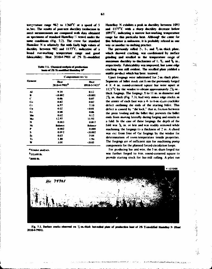
6 1
9*2 to l2aO*C at a speed of S • ^ 9 K . T V results of post-atst aWtJitr iPedacooa •
i l • m w i m air coaajarid r A tea n t r w i > of standard llasltBoy • -' tesfc*£ •p ier the
ir^c, 7.2V The «-ne for standard l l imihw N s M b o v r f y flat wah fairly b»> valaes of ductarry betweea 9«2 aad I I T T r . aafccatiac of a
fabricating- Heat 2HO4-790I of 2 * Ti
OlB» — i M u r . ) R e a m Heal Hen
M M M - T W I * t » l * -S -742 l r
Al 4 10 0.12
• <0.002 <0.00l c o.o* 0.07 Co 0.02 0.02 Cr * . * 7 7.10 Ca 0.02 <0.0I F< o.« om M B 0.02 0.12 Mb 12.97 11.93 M 0.003 0.«>7 m •abacc •abner r 0.002 0.004 s O.0H2 <0.002 Si 0.03 9 0 4 T i ISO l.9o W J.0I <0.05
'Vendor analyses^
*IO.WW>lb r MOO lb.
ffas*eaoy N exhibits a peak hi dacrarry betweea 1093 aad 1I77*C with a dorp dactiKty decrease below 1093*C. • dinting a narrow hot-working aMnperatuce
far d m particular heat. Ahhoufl- the cause for bthwiui is • f i i w i . H is probably related hi oae or another to BKrtiag practice.
The pnrnouriy roSea 2-. I- . aa4 V»-in.-rhkk plate, racking, was tDadrboaed by sarface
ad KroBed at * e toaperatare m j e of aactaty to dattaeaes of I . K . a a d ^ * i n ,
respectively- Fabncabibty was unproved, bat soaat edge a; was stii evident. The reroaed plate yielded a prrokct which has beec "eceived-
Upset lorgmgs were substituted for 2-w»-Uack plate. Segments of biBei stock cat from the previously forced 4 X 4 ia. rouad-ccraered sqaare bar were upset at I I 2 I * C by the vendor lo obtam approunatehr 1%-ia-thkk forpafs. The forgiajs. S to 11 m. at diameter and 2% m. thick (FEJ. 7.3|. had very minor edge cracks, ia the dealer of each face was a 4- to 6-tn.-cum crackbke defect outlnang the ends of the starting bh>t. This defect is caused by "da? lock." thai is. friction between the press tooting and (be owlet iha; prevents the billet ends front moving laterally during forging and results in a fold. In the case of these forging? the depth of the fold was \ in. or less and was readily removed while machining the torgmgs to a thickness of 2 in. A chord was cu: from four of 'Se forgings by the vendor for determination iff room temperature tensile properties. The forgings are of sufficient size for machining pump components for the planned forced-circulation loops.
For producing bar and wire, the S-in.-diam forged Oar was further forged to 4-in. round-cornered square to provide starting stock for bar-mill rolling. A pilot run
V-1272O0
Fh> 7.1. Sarfaci cncks 28104-7901).
m 7,-Uvdnck hot-foaaJ parte of hart of 2 * TtoodiTad Hi ia lu j N (Hart
»«*„»:9/idy, iV i * ; .

62
demat*trated that bar stock cndd be rutted with cue to about a l-m. aumrtfr at I I 4 « # \ . bm tor dtameten apparently chaanf action by the roUs excessive rra-fra% predictaMr from the
Qecbie data previoasty reported. Therefore, an attempt to product smaH-dameter bar i%- and
coid
ntermfdute annealing, treatments at H 7 7 * f \ This approach was only mipaaihr satccoi'ai. becaase inr drawn bar was IOWM) to be susotptMr to stress nwlncfd annealing cracks. This problem was panialy so!*£d by cither of two ways: flexing of the drawn prodact in straiaWnmg eonipmenr prior 10 aniKahng at 1 1 7 7 T .
) andwue(%-and%i -m. drameWTiby or loaenne the mieunedate of approximately l-m.-dtam bar wsh I I 2 I * C .
to
OaaL-OM 7S-TI9* too
• 0
6 0 z z o
4 0
20
• STD.HaSTELLOVNtHT.NaS0C5! O £%T-aXX)»TIEDHASTCLLOrNIHT.NO.?aaO-'«-79(>l)
A—-
1800 962
t * 0 0 K)38
Fh>7J-
tQOO 2IO0 2200 23COT •093 1150 «204 42CO*C TESTTElaPERATURe
t*rXmw*S0*5)m*Z%Timm4* af llamaij H (Nut 2SI*4-7Wlt
PMOTO 0«3>75
Fig. 7.3. I'paet forgfe,** of 2% Ti-inodiOtl Hastdtoy N (Hot 2SI04-790I). AporoMnufrly 2'/. in (hick.

bJ
% bar and
A sajniiicaai quantity of aurernl was estabtasJang ibr pn -Cessna; paramr ten lor | and wwc. and iialy a naal quantify of ^ t « . < i a m bar and %.-w.-dam weld wire was recmed from ibr* first heal. Huwcatr. die r d f j w n r a i for I W f i of l-m.-diam bar and JO fi of I'jl-m.-diaa* bar was mei. The fk>w dtagram i inamaii i * the process routaig for ho t 910-1-7101 I Fa;. 7.41.
The second m i IVHS-5-7421) has beca scfaedaied foi conversant lo tabaig- luaad bat. and wac I Fa;. 7 J 1 . To daw. fabneafiua has progressed smoothly with ao oradung danag hot worfcjag or damn, aaa rating after csdd worfcjag at experienced with the feu heat. The prooKsnn; parameters developed for the fast beat are being ased for the second beat.
Gkebir data fcir the second heal were obtained by the vendor aa specimens taken front 4-uv-square forged bar. The retain are compared wiih the earber data from the fast heat I Fig. 7.6|. The much broader lemperaiare range of high ductility for the second beat suggest! that greater tatitade m processing parameters is peraassMe and that the fabrication problems cnc^wniered with the f in! heat ase not inherent to ibe basic ahoy omtpusi-ima but were pecuhat to that specific beat.
The lahutg u» be produced from the second beat presents a scheduling probkm in that the vendor war be assisted by i m other cotrct;>^in sources, one for trepanniag the bdiet stock and the other for drawing to fatal sue. This resulis m a long protected delr*e;y i**ne. To shorten tins lime, a forgeo1»»; 4 X 4 X 60 in. wal be processed by an alternate route lo pioducc at least the
required tor oar forord-quaatity of t orcutalion loop.
7.1.2
Sw seaupi oductaai hears of 2*5 Ti modified HastcHoy S. four of whidi cuatam rzre-carth additions (lanthanum. oKiun. or much octal), have been included in the aSoy evaluation program. These alloys wal test the effectiveness of rare-earth additions as gettens; elements fur teauriun to irammwr shallow mtergrandar cracking. Each aftoy was a !204b doufee-meite 1 I vacuum induction pbtt dectrustag remeit! beat produced by an outside vendor. The compositiuas of the awnys are shown in Table 7.2. Because the aluminum content of beats 74533.74S34.74535. and 74539 was somewhat higher than the specified 0.15*1 maximum, two beau. 74557 and 7455S. w r c produced wi»h much less aluminum.
The 4-in.-diam ingot ot each alloy was forgeo to a 2-m.tbK-fc slab at I I77*C. then hot rolled lo '/t-in.-tlack plate at the same temperature. A portion of the plate product from each j f the heats is shown in Figs. 7.7 and 1%. The fabhcabtliiy of heats 74533. 74534. 74535. and 74539 ».as better than that of beats 74557 and 74558. «btch exhibited profuse edge cracking. There is an apparent connection between ihe aluminum coatent of the alitiys and their fabricability which may be real: but facias such as melting environment, type and quantity of finer rnalieabilixing additions made lo ihe alloy, and liming of ihcse addiiions during the
Fig. 7.4. Proem mating for lO.OCMMb neat rf 2% THnndiTNd HasMloy N (Heal 2S104-7901).
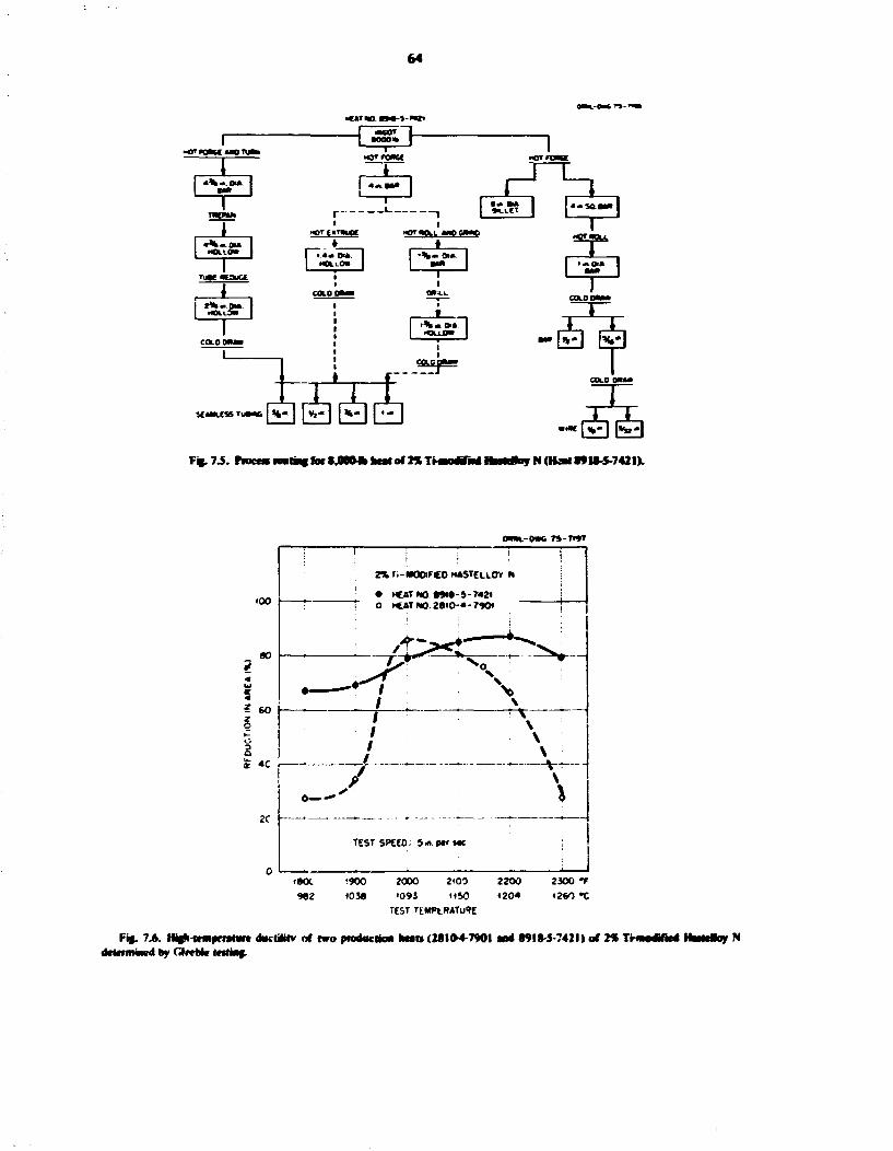
64
tkttn t—-imz.
< « n K E > a i u t i
« * • o»
M O L I O *
TutgtOUCC
, t , I A . » I > a i M I
• o o o * — I —
* 1-_ i
•< 1 _ i
•< I
«JTt*TWutt »
_ i
•< • >T«C».I i w t n o
1 I « « C M . 1 | I O L L O * f
_ i
•<
• M | 1 1
COLO O M B
_ i
•<
1 1
DT4.1.
HOT react
HOLL0B
o-gf rtrf JCMLCSSTUC*HC [H« I | ^ * | <fc- |
Ffc.7.5. rroccsio«tincfo«S4>0(M»IMof 2%TMn0dTMd
p-SOBKlj
I •Sia&L
• —0i» I T
-S COLO on—
N<tfcatf9U-5-7421).
O m - 0 K TS-TUT
tOO f~
80
* 60 z o
a? 4C
Z% Ti-MOOlFCO WASTELLOY N
• HCAT NO SSta-S-7421 O HEAT NO. 2 » i 0 - « - 790<
2C
0—
TESTSPEEO: 9m.strMC
tBOt '900 2000 2 '00 2200 2300 f 9"2 )03« >093 1150 «204 «2V) *C
TEST TEMPtRATu»E
Fig. 7A HifH-ieiNfriamc AKiWrv of two production Heats (2SKH-790I and 89IS-5-742I) of 2% THnodtffcd Hnmfoy N determined »y df«Me letting.

65
Tatar 7.2. i r f R T i B i nav/M* ftOT » j v I I H 1
Cu—fumium ««n %)
FJeaacat »ca Heat Heat Heat Heat Heat 7<S33 743.4 74S3S 74539 74557 74556
Al 0.4B 033 0.55 0.20 0.02 0.02 b 0.002 <aoo2 0.002 0.002 <0.002 <0.002 C 0.05 0.0t 0.0B 0.0S 0.04 ao7 Co 0.03 0.03 0.03 0.06 G 7.02 7.12 7.30 7.14 7.23 7.20 Cm <0.0I 0.02 0.CI 0.01 <0.0I <aoi Fc o •» 0.06 0.05 0.07 0.0S 0.07 Ma <0 <0.01 <0.0I <0J>l <0.0I <0.0I Mo I U I I . M 11.79 11.47 11.91 IZJOQ N 0.005 0.007 0.006 0.006 0.009 J012 !* Balance Balance Balance Balance Balance Balance S <O.002 <0.002 <0.002 <aoo2 0.0012 0.002 Si 0.03 0.03 0.03 0.04 0.03 0.03 Ti 2.17 2.09 2.13 1.93 2.14 2.05 W 0.14 0.14 0.10 0.11 0.02 0.02 La 0.013 0.01 0.02 Total HE* 0.04 a 0.03
'Vendue anatyw?.
* R F : rare cart'*.
Ffc. 7.7. OmttMKJMmkk k o t - f o M nlate of tnmm/io4mctkm heat* of 29 TMnrMlifM HuteBoy N. Heal 74533 2'5 Ti Bate Compmilion • 0.4«T Al. Heal 74534 law compmitinn • 0.53T Al • 0.0!.V- U . Heal 7453"» batelompmition • 0.20^ \\* 0.03" Ce. Heal 74535 ba«e i»mpo<iilion • 0.55^ Al • 0.0*'; Mnch metal.

66
f
V 127301
*%.!*. O M t^Kimtk • « > fcni « • •« ft/it tt «wi»-e»cliu > lieato of » Ti wolWil compoulion• 0.0^: Al. Heal 7455* b»corapmwion• 0.02^ A l * » 0 2 ' La.
N. Heal 74557 >-cTikuc
melting operation can also significantly influence labri-cability.
Gleeble evaluation tests were performed on heals 74533 - i d 74557 over the temperature range 982 to I260°C (Fig. 7.91. The results are consistent with fabrication exper-.ncc in that bent 74533 showed excellent ductility between 982 and 1200°C. and the ductility of heat 74557 fell off sharply above 1150'C. Both alloys were hot worked at 1177 C.
Current studies on the semiproduct ion heats include voidability and the measurement of mechanical properties in the irradiated and unirradiated conditions. Weld wire and mechanical-proprrty-specimen stock we<re obtained by swaging strips cut from the V 3 i n -thick plate. Tubular specimens have been machined from heats 74533 and 74534 for future fuel-capsule sttM&s. In addition, an attempt is being made to process welded and drawn tubing of deals 74533. 74534. 74535. and 74539 to provide specimen slock for strain-cycle and in-reactor fueled-capsule testing. The tube blanks were produced by rolling Vj-in.-lhick plate lo0.140-in.-thick strips and then cold forming the sheet into semicircular (clamshell) stupes. The seams of pairs of the clamshells were closed by electron-beam welding, and the blanks arc now ready for drawing.
Typical tube blank* before and after welding are shown (Fig. 7.10).
7.1.3 LatmKory Heats
Earlier work has shown that niobium additions to titanium-modified Hastelloy N enhance resisiance lo tellurium embrittlement. Aluminum is also an important addition to these alloys, since it is often used as a deoxidi/er during melt preparation. However. Nb. T i . and Al can combine with Ni to form intermeiallic compi>jnds causing embrittlement of the alloy. Therefore, laboratory heats based nominally upon Ni I 2 r ; Mo 7*? Cr with varying Nb. Ti . Al. and C contents are being studied to determine the concentrations of these elements that can be added before precipitation of iiiiermetallic compounds occurs.
The alloys (Tabic 7.3) were prepared at 0 R N L as I in.-diam. 2-fb ingots by arc-melting and drop-casting techniques. The ingots were worked to %-in.-diam rod by hot swaging at I I77°C from the I-in. diameter to approximately 0.437-in. diameter and then to final size by cold swaging using intermediate anneals al 1177°C.
Solution-annealed specimens of the alloys have been subjected to aging heal treatments between 650 and
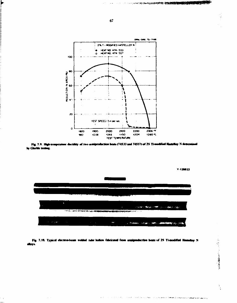
'^^~l*&»&eg**!¥%&!!8 «g
67
0MH.-OBC TS-T»»«
2000 »0»3 TEST rE»PE&ATu«E
2K-0 2200 2306 f M50 «204 i 2 U t
R ( . 7 . * brGltrUr
4»iHl«> of two (74533 Mtf 74557) of 2*
v 12M22
Ft- 7.1*. Typkrf cfcctRMMiMm MM* of » THUotfiM HMMpy N
I

68
TaMr7-3. Cawirw i—S/nVofMuiimy tola
Nfc. Ti. AS. awj C CMMMtf
Hrai i'ompusitiuii Iwl .')
Hrai Nb Ti Al C
427 2.40 0.18 0.14 42S 2.47 0.16 0.064 429 2.40 0.35 0.017 430 2.50 0.34 0.073 .31 2.50 0.74 0.016 432 2.35 0.69 0.057 418 1.2 2.0 0.05 0.OSS 424 1.0 I.S 0.10 0.063 420 1.1 1.8 0.15 0.055 435* 1.5 2.3 0.25 0.04 43»* 2.0 2.3 0.25 0.05 433 I I I y 2 0.33 0.024 434 1*8 •» •> 0.32 0.061 4 4 1 * 2.5 .3 0.25 0.05 442 3.0 2.3 0.25 0.052
*H»c: Si-12^ Mo 7~Cr. *Nomml cumputiima.
800°C and are being evaluated for lability (absence of inlet metallic compound precipitation I by post-heat-treatment hardness measurements and mkrostructural analyses. Mechanical property specimens of certain of the alloys have been prepared and are being creep tested in both the irradiated and unirradiated condition*.
7.2 WELDAMUTY O f COMMERCIAL ALLOYS OF MODIFIED HASTELLOY N
B McNabb H. E. McCoy T. K Roche
As shown by the successful operation of the MSRE. Hastelloy N a fabricaMe and weldabie to quality ieveb required for nuclear reactors. Modified compositions of Hasteiloy N with improved resistance to radiation damage and tellurium embrittlement must afcc fulfill these requirements for use in an MSBR. Sir small semiproductkm heats (120 lb) am. two large production heats (8000 and I0XJ00 lb) of modified Hattdloy N containing approximately 2% Ti . with and without small rare-earth additions, have been received from an outside vendor. The chemical analyses of these heats are sho» in Tables 7.1 and 7.2.
Ine six small heats were each received in the form of four pieces of '^-in.-thick plate approximately 5 in. wide by approximately 24 in. long in the rolling direction. One plate of each heat was cut in half and the edges beveled to give a 100° included angle when placed
together for welding, thus yielding a finished welded plate approximately 10 in. wide by 12 in. long. Strips '/j in. by V; in. by 12 in. long were sawed from one plate of each heal, the corners were rounded, and the bars swaged to % in. in diameter for mechanical property tests. Some of this %-in.-diam rod was further swaged to V and % ; - in -dmn weld wire for autogenous welding of the prepared weld plates. Intermediate anneals at 870°C in air during swaging stress-relieved the material, and sand Masting removed the oxide after swaging. The weld wire was electro-chemically cleaned and the prepared plates were cleaned with acetone before welding.
The first product received of the 10.0004b heat (74**) I ) was a plate approximately % in. thick. 6 in. wide, and 24 in. in in cross-rolled direction. This plate was cut into two pieces, each approximately 3 X 1 2 in., and the remainder into % -in.-square strips for fabrication of wire and rod. The plate and wire wvre prepared for welding by the same procedure as ti:e small heats.
Prior to the weld test, plates were welded to a 4-w.-truck steel strongback to achieve a restrained condition. All welds were irode by ORNL Welding Procedure WPS 1402. bach pass was visually inspected, and the first, third, and firwl weld passes were inspected with dye penetrant. A wire brush was used as needed to dean the surface between passes. Weld wire having a diameter of 7j j in. was used for the root and next two passes, and V i n . - d j m wire was used for the approximately 20 remaining passes. The root, second, and fourth passes were made with the weld plates at room temperature, the other mlerpass temperatures averaged about 93°C. The root pass was made at approximately 14 V and 85 A. pass No. 2 at 110 A, No. 3 at I IS A. No. 4 at 17 V and 180 A. and the remainder of the passes at 17 V and 190 A. After the welding, the pbies were x-raye<*. no cracks or porosity was noted for any of the plates. The wel-H were sound, with no cracking found either visually or by dye-penetrant inspection.
Side-bend specimens '4 in. thick were sawed from the welded plates and dressed down on each side with an abrasive grinding wheel. These were then bent in a %-in.-radius bend fixture and dye-penetrant-inspected for cracks in the weld. Figure 7.1 la is a pho:~fraph of the tension side of two such side-bend specimens of heal 74S33 (modified Hastelloy N. 2.1% Ti 0.48% Al). One specimen shows no flaws, and one has two small indications at the edges but still should pass the side-bend test, which allows open flaws up to '/,» in. Figure 7.1 lb is a photograph of the tension side of two side-bend specimens of heat 74534 (modified Hastelloy

69
Ffe 711 FfcoloflMte of ^teAn^ S K ^ M M of Onr*. (*) Hwi 74533. (b) Hat 74334. (c) Hoi 7453S. M*.
N. Drt pwMlwm h« bwn apptM- D»rfc »poi» mtktu
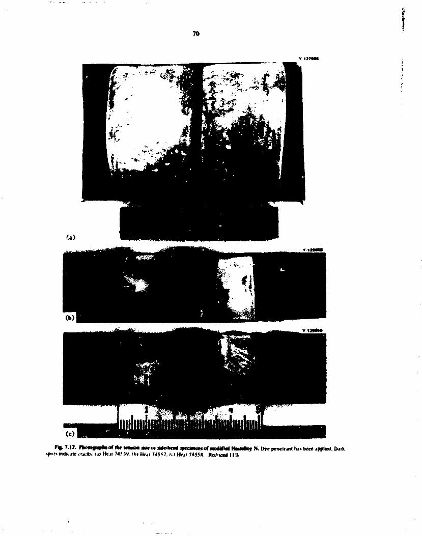
70
f%. 7.12. rkrwignrfaor Ifc* H M i M A K m ri*c*m* »«cwn.»*of mo4iM H a r t * * N. Dye penetrant ha* been applied. Dark %pi>(» indicate crack*. <a» Heit 74539. tb) tfeal 74557. ui Ilea* 7455*. RiV'icni I \%
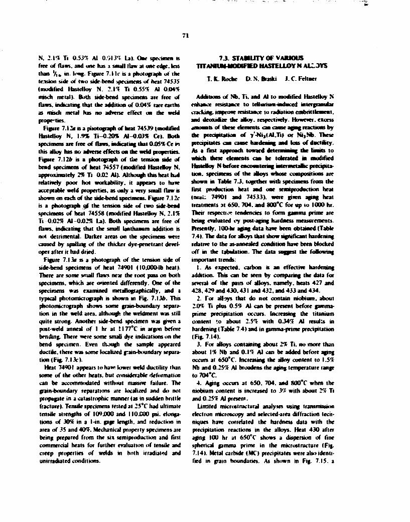
71
N. 2 .11 Ti 0.53-* Al 0-0131 La). One specimen is free of flaws, and one has i small flaw al one edge, less than '/,» in. long. Figure 7.1 I r b a photograph of the te.-tsion side o( two side-bend specimens of heat 74535 (modified Hastdloy N. 2 1 1 Ti 0 .551 Al 0 .041 rasch metal). Both side-bend specimens are free of flaws, indkating that the addition of 0.041 rare earths as mbdi metal has no advene effect on the weld propfties.
Figure 7.1 2* is a pitotograph of heat 74539 (modified rfastdloy N, 1.9% Ti-0.20% A l -0 .031 Ce|. Both specimens are free of flaws, indicating that 0 .051 Ce m this alloy has no adverse effects on the weld properties. Figure 7.12* b a photograph of the tension side of bend specimens of heat 74557 (modified HasteHoy N. approximately 2 1 Ti 0.02 Al). Although thb heat Ibd relatively poor hot workability, it appears to haw acceptable weld properties, as only a very small flaw is shown on each of the side-bend specimens. Figure 7.12r is a photograph gf the tension side of two side-bend specimens of heat 74558 (modified Hastelloy N. 2.11 Ti 0 .021 Al 0 .021 La). Both specimens are free of flaws, indicating that the small lanthanum addition is not detrimental. Darker areas on the specimens were caused by spailing of the thicker dye-penetranl developer after it had dried.
Figure 7.13a is a photograph of the tension side of side-bend specimens of heat 74901 (I0j0004b heat). There are some srnoll flaws near the root pass on both specimens, which are oriented differently. One of the specimens was examined metallographically, and a typical photomicrograph is shown in Fig. 7.13d. Thb photomicrograph shows some grain-boundary separation in the weld area, although the wddment was still quite strong. Another side-bend specimen was given a post-weld anneal of I hr al ! 177°C in argon before bending. There were some small dye indications on the bend specimen. Even though the sample appeared ductile, there was some localized grain-boundary separation (Fig. 7.13r).
Heat 74901 appears to haw lower weld ductility than some of the other heats, but considerable deformation can be accommodated without massive failure. The grain-boundary reparations are localized and do not propagate in a catastrophic manner (as in sudden brittle fracture). Tensile specimens tested al 25°C had ultimate tensile strengths of 109.000 and I I0.C00 psi. elongations of 3 0 1 in a I-in. gage length, and reduction in area of 35 and 4 0 1 . Mechanical properly specimens are being prepared from the six semiproduction and first commercial heals for further evaluation of tensile and creep properties of welds in hoih irradiated and unirradiated conditions.
7 J . STABILITY OF VARIOUS TOAMUltMOOIFIED HASTELLOY N ALL JYS
T. K. Roche D. N. Brasfci J. C. Feltner
Additions of Nb. T i . and Al to modified Hastelloy N enhance resistance to tellurium induce i intergranubr cracking, improve resistance to radiation embrittlement. and deoxidue die alloy, respectively. However, excess amounts of these elements can cause aging reactions by die precipitation of 7'-Ni,(Al.Ti) or N i } N b . These precipitates can cause hardening and loss of ductility. As a last approach toward drlfrminins, die limits to
HmeBoy N before encountering jntermetaBic precipitation, specimens of the alloys whose compositions are shown in Table 7 J , together with specimens from the first production heat and one serniproduction heat (neat: 74901 and 74533). were given aging heat treatments at 650. 704. and 800°C for up io 1000 hr. Their respect i.» tendencies to form gamma prime are being evaluated oy post-aging hardness measurements. Presently. 100-hr aging data have been obtained (Table 7.4). The data for alloys that show significant hardening relative to the as-annealed condition have been blocked off in the tabulation. The data suggest the following important trends:
1. As expected, carbon b an effective hardening addition. Thb can be seen by comparing the data for several of the pairs of alloys, namely, heats 427 and 428,429 and 430.431 and 432. and 433 and 434.
2. Tor alloys that do not contain niobium, about 2.01 Ti plus 0 .51 Al can be present before gamma-prime precipitation occurs. Increasing the titanium content to about 2.51 with 0.341 Al resulu in hardening (Table 7 4 ) and in gamma-prime precipitation (Fig. 7.14).
3. For alloys containing about 2% Ti . no more than about I I Nb and 0 .11 Al can be added before aging occurs at 650°C. Increasing the alloy content to 1.51 Nb and 0.251 Al broadens the aging temperature range to 704°C.
4. Aging occurs at 650. 704. and 800°C when the niobium content is increased to y% with about 2 1 Ti and 0.251 Al present.
Limited mkroslruclural analyses using transmission electron microscopy and selected-area diffraction techniques have correlated the hardness data with the precipitation reactions in the alloys. Heal 430 after aging 100 hr at 650°C shows a dispersion of fine spherical gamma prime in the microslruclure (Fig. 7.14). Metal carbide ( M O precipitates were also identified in grain boundaries. As shown in Fig. 7.15. a

i 127»6»
> r ~
1
(c) too 20
—L-. L 0.OO5
^ \ X > .
(b)
I
F«. 7.1 J. Modified HarteMo? N Heal 74901. (1 1101 mdka'r (law» or cratkv (hi PtiofomicroKrjall (t I Pholomkfofrjph of bend 110 of side-bend tan

BLANK PAGE

WM-JL1J P1L- »•.• W W " ! iM.'s**? -i
72
'- "\
(c) 100 200 - S L - r
MICRONS — 100X 1
6 0 0
0.005 0.010 INCHES 0.020 0.025
7 0 0 I _ ' I I
f'%. 7.13. Modified Hastriloy N Heal 7490!. (a> Photograph of tension side of side-bend specimens, dye penetrant applied. Dark areas indicate flaws or cracks, (b) Photomicrograph of bend area of side-bend specimen as welded. Elched with glyceria regb. I00X. (c) Photomicrograph of bend area of side-bend specimen given a post-weld anneal I hr at I I77"C. Etched with glyceria regia. I00X.
2

73
7.4. Pvdacsofvariovshcatoor a t e apag NO hr al 450.78*. mi
!•«
Data in Mucks indicate HtMfkaat haideoiag rcblnc lo the as-anncakd coodiuon
CofBpOSlC MR ««l %) Rockwell B haidacs
Heal CofBpOSlC MR ««l %)
Aged 100 hi Heal Nb Ti Al C
Aged 100 hi Nb Ti Al C
650*C 704*C soo*c
74901 1.8 0.10 0.06 79.4 81.8 82.9 85.1 427 2.4 0.18 0.014 74.7 74.9 76.5 77.4 421 2.47 0.16 0.064 82.5 84.2 8VI 84.7 74533 2.17
2.4 0.48 0.35
0.05 0.017
81.0 76.9
84.3 84.6 SOI
85.4 429
2.17 2.4
0.48 0.35
0.05 0.017
81.0 76.9 89.5
84.6 SOI 79.8
430 2.5 2.5
0.34 0.74
0.073 0.016
88.6 78.6
95.7 90.9
90.7 SS.6 431
2.5 2.5
0.34 0.74
0.073 0.016
88.6 78.6
95.7 90.9 9S.» 91.9
432 1.2
2.35 2.0
0.69 0.05
0.057 0.058
87.4 89.1
98.8 99.9 98.2 418 1.2
2.35 2.0
0.69 0.05
0.057 0.058
87.4 89.1 90.0 90.1 89.9
424 1.0 1.8 0.10 0.063 88.6 89.3 89.1 89.9 420 1.1
1.5 i.8 2.3
0.15 0.25
0.055 0.04
88.7 88.6
100.8 102.5
90.3 88.5 435*
1.1 1.5
i.8 2.3
0.15 0.25
0.055 0.04
88.7 88.6
100.8 102.5 100.6 87.3
438 c 2.0 2.3 0.25 0.05 91.8 103.9 103.2 91.6 433 1.88 2.2 0.33 0.024 84.8 102.2 101.5 86.7 434 1.88 2.2 0.32 0061 93.3 104.5 103.2 92.0 441 c 2.5
3.0 2.3 2.3
0.25 0.25
0.05 0.052
93.1 95.0
107.5 108.1
105.8 108.0
V7.9 442*
2.5 3.0
2.3 2.3
0.25 0.25
0.05 0.052
93.1 95.0
107.5 108.1
105.8 108.0 10S6|
2.5 3.0
2.3 2.3
0.25 0.25
0.05 0.052
93.1 95.0
'Base: Ni-123 Mo-ll bl hrat M 7 r c . 'Nominal composition.
Cr.
coarser dispersion of gamma prime was found in heat 431 after aging 100 hr at 800°C. This alloy also contained small blocky MC precipitates both at grain boundaries and within the grains themselves. The microstructure of an aged niobium-containing alloy is presented in Fig. 7.16. Heat 433 was aged 100 hr 3t 704° C and contains both NijNb and gamma-prime precipitates. Carbides of the MC type were also identified in the alloy and were generally concentrated in grain boundaries, whereas the NijNb and gamma prime were dispersed uniformly throughout the grains.
This study will be continued by extending the aging times and by measuring the tensile properties of certain of the alloys to determine the effects of aging on strength and ductility.
7.4 MECHANICAL PROPERTIES OF TITANIUM MODIFIED HASTELLOY N ALLOYS
IN THE UNIRRADIATED CONDITION
T. K. Roche J. C. Feliner B. McNabb
The mechanical properties of the latest production and semiproduction heats of 27r Ti modified Hastciloy
N are being determined in the unirradiated condition. These data will serve as a reference for comparison with the properties of standard and other modified Hastelloy N alloys both in the unirradiated and irradiated conditions. Included in this work are the determination of room- and elevated-temperature tensile properties and of creep-rupture properties in air at 650, 704, and 760°C. Facilities will soon be completed for performing creep-rupture and strain-cycle tests in fluoride salts.
The room-temperature tensile properties reported by the vendor for specimens taken from the various mill products received from the 10.000-lb production heat (74901) of 2% Ti modified Hastelloy N are compared with data from three earlier semiproduction heals of the same alloy and with typical data for standard Hastciloy N (Table 7.S). The yield strengths of all heals fall in the range of 43.000 lo 53.000 psi: f'u.ther testing will be required to determine whether the differences are significant. The ultimate strengths for the products of the 10.000-lb heat are slightly less than those determined for the earlier heals of the 2% Ti modified alloy. The lower ultimate tensile strength is accompanied by a lower elongation: both properties may be a reflection of fabrication history. The elongations of the

74
Y-128782
Fig. 7.14. TransmBMon electron micrograph of Heal 430. (200-300 A diarn) and coarar MC precipitin
100 hr at 650°C. mowing diaperskm of a^haical gamma prime
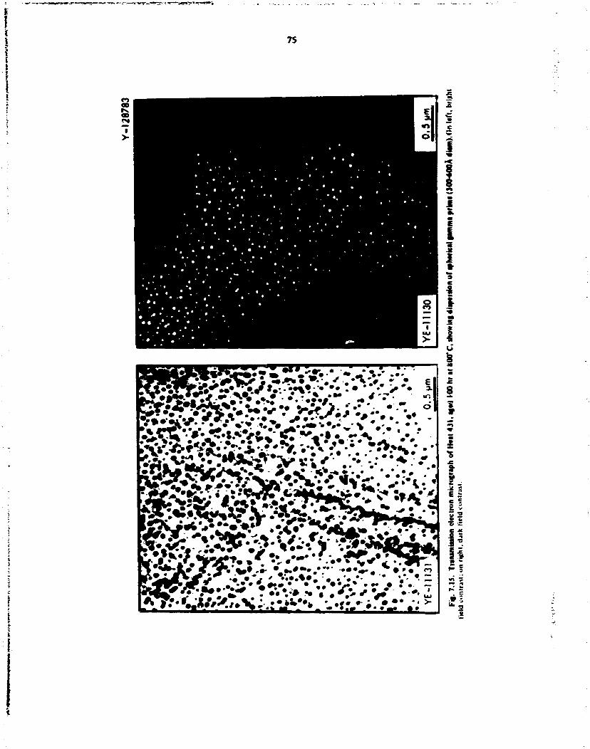
7S
i I !
i
s 9
fl
_ w» *
^

76
S

77
r7.5- O < 2 t l » 4 - 7 9 « l » a r » r i
L I IBPJ IV im«fc tircu • I I I 1 (Mil
YicMurcvt • I " ' put
tiuacaliuii « I
II
?-in--lfciit U«pmr Hn.-ifck.-k pbic .-ai-ihwk pbtc
t-aL-sh*.-kpLiic tnr
hi i
b r a l | 2 * l » - * - 7 9 * l ) a f n T i i
111.5 118.5 1I4.M lll.VO M3.5 I 1 3 J
Swaged r.-d I beat 711'.-t; Saocnl rod (heal 715831 Ssaccd f»d Iheat 725«3>
Typical
k a t t o r n T . ;
I2«.7 I2«.» 123.S
115.1
45.11 65.0 46.5 64.6 .J.ii 64.5 4 * 5 6O.0 53.5 63.3 SII.O 64.:
44.8 45.9 46.0
45.5
72.6 73.3 6S.7
5«.ir
'AH tpvv i m m aimcatcil J I 1177 * m J I D K I P»MC i<> tola
70
60 f •
J in 4 0 «i w oc
30
20
ONWl-OwS 75-7700
to
- 2 % T,-M00iF:E0 H4STEL1.0Y N ^ [HT HO 471-M4)
10
0 474-533 • 4*4-534 A 474-535 A 474-539 • 474-557 • 4 7 4 - S C * O 4 7 4 - 9 0 1
. . L
5 10' 10 J
»UPTU»£ *!»V_ (hr)
Fif. 7.17. Sttct*-njff M C pmavrlies of srvml heals of 2% TVmodifM Hastcfloy N jnd standard lbiH»u> N at 65V C.

78
modified heats are greater than tor standard rtriteHoy N In general, the tensde properties or' the T< Ti modified aMov are about the same as those ot" standard tfastctloyN
Data from creep-rupture tests in air are being obtamed on the latest heals of Ti Ti modilied Httteiloy N. Tests currently in progress are designed to estabhsh reference creep and stress-rupture curves at 650. 70* . and 760*C. Specimens were obtamed from swaged rod of the various alloys and were annealed I hr at I I77*C prior to test. Stress-rupture data obtained to
date are given in Table 7.6. These same data are compared vnti: stress-rupture curves for standard rfaslelloy N and a previous heal ot Ti Tionoditied IbstcUuv N |Figs. 7.17 and 7_I»». The newer heats of Ti Ti-modiiied .bsteHoy N are essentially equivalent in strength to the earter heal, and there appear to be no ugrulkant effects frum the rare-esrth additions to tr<e Ti Ti-m-wfelWd aUov. As determined from past work and confirmed by the recent tests, the modified alloys exhibit longer rupture lives than standard HaslcUoy N at both temperatures.
> K a t tS* art 7 » r c *
Heal* An>* Tot OHMfcllH** R^lar r
Me Ihrl
T»ul Heal* An>* Sirc«
1 l<»J pw» TcapcTjiwe
R^lar r Me Ihrl
cii»aulii>a 1"»
74533 KwT 4o 47 55
*5«» 650 650
I4S6 465 112
27 2 * 21
74534 Bur* 7 * 0.013^ L i 47 55
-SO 65«
3«M 136
43 51
74535 BafcT * 0 .M m o i l mclJ 40 47 55
650 650 650
l*S3 591 166
36 33 3S
7453* B a « f • 0 .031 Cc 47 55
650 650
1467 137
43 43
74557 Buc^ 47 55
650 650
302 70
20 1 *
7455* • a V • 0 .02- U 40 47 55
650 650 650
1554 413 139
25 27 26
74901 lO.OWMb prndiKImn Scat 40 47 55
650 650 650
1247 395 117
26 27 24
74533 Base' 35 704 19* 42
74534 n W • 0.01 J~. U 30 35
704 704
30« 172
37 46
74535 Bate2' • 0 . ( H - miKh metal 25 35
704 704
107* 193
43 52
74539 Rn**" • 0.II31 ( c 25 »5
7«4 704
1137 187
42 63
74557 h . / 35 704 207 45
7455* Base* • 0.02T. La 35 704 1*9 44
'AD specimen annealed I hr al I I77*C in Ar prior In testing.
"See Tables 7.1 and 7.2 for detailed chemical composition. c N i 12% Mo 7% Cr 2% Ti 0.06 C.

79
OaS T 5 - W M
F*.7.lt.
AUPTuRCTlMe (kr)
N ] XMTCC
7.5 POSTlRRAOlATrON MECHANICAL PROPERTIES OF MODIFIED HASTELLOY N
H. E. McCoy
Samples of I I R modifVd compositions of HasteUoy N are irradiated in the Oak Ridge Research Reactor (ORR) and subjected to postirradialion creep tests to evaluate the influence of irradiation on the mechanical properties. Samples of the heats shown in Tables 7.1. 7.2. and 7.7 have been irradiated under several conditions and are ready for creep testing- Twelve in-celJ creep machines are available for this work. The test matrices are fragmentary at this time.
Figure 7.19 shows the postirradiation s'ress-rupture results al o50*C of several heats of Hastelloy N containing nominally TX titanium. The fracture strains are shown by the individual data points. These samples were irradiated at 6S0*C in the ORR poobide facility lo a thermal flusnee of about 3 X 1 0 " neutrons/cm1. The minimum creep rates (Fig. 7.20) for many of the same tests indicate several important trends.
I . The variation in rupture lives for the heats is large (more than a factor of 10 from the shortest to the longest). The titanium concentrations vary from 1.4 to 2.2%, with alloy 471-583 containing the least and
dkry 474-533 the mosi. but the variations m rupture life do not appear to b> simply proportional to the titanium concentration.
2. Mmunum creep rates vary by a factor of lO. but generally less than the variation noted for the rupture life.
3. Both the rupture life and the minimum creep rate vary considerabfv for the heals in the unirradiated condition.
4. The rupture life of each heal except 472-503 b reduced by irradiation. The rupture life, minimum creep rate, and fracture strain for this heat are extremely good.
5. The rupture lives and fracture strain* of all other heau are reduced by irradiation, but the extent of reduction varies from heal to heal.
6. The minimum creep rale does not appear to be influenced by irradiation at lower stress levets. but the minimum creep rate does appear to be increased at the higher stress levels. Further analysis of the individual curves will oe required to conclude whether this is a true effect.
7. Heat 7 34)08 has the lowest fracture strains of aB heats evaluated. Electron microscopy has shown thai this heat has an inhomogeneous. generally coarse carbide structure.

TaMt 7.7. Analyati at wvvral haali of Mamlanl ami mwWM fli tftitoy N
I I * 41 4 *lfb««NM4l|*>«1 IW1 1
Mimta^ i i M. i . 1 Si u» ¥ s M •
ti lNaM
h
: i
Mi
• n i l
/ i
»!• ' . ' I ' 4 M i ' <i.i« H04 • i i i l l ii I I
s M •
ti lNaM
h
: i
Mi
• n i l m l 1 '1 114 »4 u» •••».< III4R n i l . * * M i l * IIIHIT Mil l IM.) maHai*. I »< n i l
- | U l ' J * i ; 4 » n I I I } ) l l l l l t I I I I I IIIHIT I I mM < • . * I I I U W l l 144 i n l J« t i l l »*» u t H I M * D I M I I ran ft I I I HIMIM •i mi.' II IM IIINNNI? .' Ik it m i l l i n l l >.'*II4 t i t I I i •>UM • I I I I » i . > I I I I I man IMMIi I I I ! • i imNHi; l i m n •i 1.* • IMI*I ' M l * J u l i t * I I »i u r t l I I M i l H i l l ii mi,** m a i * I l l * i imaai . ' • m a i l • Ik. ' M i l l D I M l » l I J 4 II IK ll lTH I I t i t «« i n n I I m i l .' 1 <•»« ' 1 i » it 411 I I I * 11 U II «* . I I . i l m a n m i l
M, » • H i l l VIM
I I I « H ; i n i a a i i m i ? IIINIT VIM n i a i ' l null i l l m i l t V I M ' I I V M n i a m i m a i l ? I I l i t I I in II I I I • II Ul . m i l II HI V I M ' I W • 1IHMIN IMHI I I II ut H i l l • ii lait • H i l l • m i * I I m MM H I V M maaM ii m i l l 11 Hi I I I I ) • I I tai l • H i l l • H i l l m i l VIM* MM • I IHI IH I I mi l V I M ' I I V M
An «Hll«4
•HW t»V4i M H K N M «H irfWn ****J tttMk . i p f f l i i ••! " 4 " * h h t i m**ns t»Ml llw ' / , •» -Mlfcl. *\iw\^nf4 pU l * * -»* .u i *>**<• -.High ' 4HM, iWaiftftJ m W l i i ' , Ht ****Ht I INJ
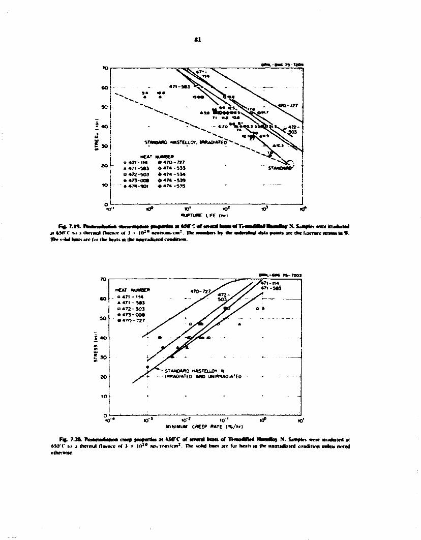
SI
CO
so -
* 40
5 JO
2 0
«>
- M M 7 » - H O »
^
. • • • :
. _ . _ . _ 4 7 I - J 0 3 ^ S. - V . r-„ . _
^ »« « • N> O* ^ ^ ^ 4 A •»••>, s>v^ ^ s — " > ^ - " N ^ l O - t t / .
* * * ^ " > * •
4 * 4
• A * 1 ^ ^ J ^ * - •
• A * 1 ^ ^ J ^ * l > < V 4 7 J -
-»* -<. "-V.^ ? •
STMVMNC N A S T E L L O * . W f c H * A T r o * ^ . s . " ^"V "• V • C * T MUMBEN " X
0 ATI - I M • 4JO - 7 2 7 <*>o A 4 7 1 -5«3 • 4 7 4 -533 ' S T 4 N 0 M O 7
0 4 7 2 -503 • 4 7 4 - 5 3 4 • 473-OOB 0 4 7 4 -53» t
* 4 7 4
-
- » • • 4 7 4 - S M i
i 1
«-' «» 10* *UPTia»£ LFE f»rt
al * y r r lo J thermal (tank.-* « l } < I 0 2 * M H M B ' ( n : . The T V *-<M haes are I 'M the beats m the mrradiaKd ctmouma-
tarn by ike
* . Sxmplrs were nadBMd •aia pmats ate the iVacrarc irra—i m • .
TO
CO
SO
4 0
5 30
20
IO
MCAT muwK* O 471 - 114 4 471 - 583 a 472- 503 • 4 7 3 - 0 0 * • 4TO-727
»7l - t14 471-5«3
eae 7S-720S
STANDARD HASTEuOr W WAOlATEO ANO UNI**A0<«TE0
«r to »0" r* »0 .0° MlHlMUM CACEP RATE (%/» ' )
w'
F»> 7.20. PujUnartitfiiHi m e n pmfwtkjt * A5MTC of srvml bato of T H W O V M I I W U B U > N. Samples were irradiated at 65<f (' l.» a thermal (lumce of 3 x | 0 } 0 nch'imn/cin 2. The wild lines arc fur heal* in (be untrradutcd conditirm unlets noted otherwise.

82
& Three heats 1474-554.474-53**. 474-5351 ( M D w d a n ! addrtionT of rare-eatth elements, bm the posorradrauo* properties of these heat* appear
•i lo those ol hat 474-533 (tarn the u v ich d*J M coniam a rare-ear th-ekmt m
The data presented MI Ftp. 7.14 and 7.20 are lor samples irradnted ai ©50*C. Ii was mown prem-msiy dkaC nradntton ac higher fenwrerafores cacse* a farther decrease w the rvptose hw and stram.1 That chaner n associated with carbide coarsemhg and *anes from heat to hot. This snbiect can be dealt with more owantiia-timtjr after the cmfhtiow of additional pustinadiatiun creep tests.
A MMber of rests have been completed winch ttroagty suggest that the postinadBtwn creep properties of the iiijnoMniiibwfk.il atoys are sensitive to the preirradBlion atmeatmg treatment. The pust-irradatmn testing is not cumpteie. and the data have
not been cnticahV renewed lor errors. W « B drfrKwh to make firm cundnsfcins yet. One of the more complete sets of data a shown m Table 7Jt for dtsenst**,. The prenTadauon anneals at I03K and I9»3°C fHdted m short mptnre hres md fractnre strams r-reidty less man IT . fwirradat*un anneahng at l l ^ C resulted M voiar mnworemeM m ruptme ntc and Jacinto - \nnnhng at I W c readied m shgwiry lower •racime sirams. bot the inp»m« We and wnm-m n «.wep rate were improved, hureaimt, the moraine tempeiaime to ! > 0 Y earned a dramatic decrease m the rupture hie at a grren stress and a decrease m fracture strain.
AMfcmgh the trends dnewssed above are pent rally snpported b> the <ata. there are some tests whack Jo not lit w tins pattern. For -sample, there shuwM fce
I . WW OKSl -5« l l . fo> .6 I
JU-p H ( SI / » V
• T i 471-114k
rTCWTJOOtliHI Si no* no' r*>
Raptor M r Ibrl rale
I :%r»
I.Kol diM«Mlin«
«" l
35 4.7 O.I»|4 0.33 » 6.0 O.OIO 1)4* 25 * A . 2 orw22 0.7*
35 0.7 n.2n 0.22 JO 34 0.029 n.l» 2« 1715 o.imo» I K
35 1.6 o.i 7 2 3 30 * 3 6 O.029 3 6 30 25 14*3.6* IMI042 *.fc 20 2SSO.0 o.rmio X.I
47 27 3 O l ! * ! 7.1 4«> 223.it O.OI 1 3.6 35 6*3 3 OI1D44 4 0
35 o.3 o.3 2.7 2$ fcn.o oo»2* 0.35 15 27*2.1 o.noti6 2.1
I t 1 l I 7 I 2 1734
16*2 1746 1719
16*3 1706 17*6 1715 I712
177' 1737 1643
1694 I72i» 1794
A A A
K » n C c < •
<" r D l> I )
I I I
*A jnncjlcd I ht4l l'»J**C in jrp»n * j iHKjkd I h u l |093'f" m jrpMi C mnnkd I hr A I I 77"C in jupit 0 aiuw^kd I br j i ' l2o4~f ' in jrpm. 1 4nncjkd I h u i I260"f" in jrr»n
l>r*o>nlinucd prh* lo failure.

63
ante «MHHr m dV i c d w ferns of lots R-I69I and K I M 2. dK icsaks of lots R-|70» aad R-I7S6 run at "cqavakM" iindMmni do not coanme favomely. and Ac Iractne stram of lot R-1720 « M loo low. Moor
mommd to dete*mme dK ine effects of •vanadaaoB anncaing caoojtMHK. tne ponnue cKccts of mnomo-y j i i m jo ihr ten samples and of unknown monies • i ien paraawjtm w0 he exptoicd-
7J» lOCKOSTmUCTUtALANALYSBOF TnAMU»HGCVKOaAS1FUi ) r rN
D. X. ntariri J. M. Leimmter C. A. rotter
H B —ritajarina was lo ami nan why two Wow— w i f w i HMcloy X head. a * * * 472-503 1503) and 471-114 1114). fcanog m d k idenacal coMfOMinH (Table 7.7). diipli>«« sadi drftorem postniaJoOun creep properties. The problem m apnojilMd by exaaaaing die mkrostructare of both aaoys M detail afief I ounce apng at 650. 704. and 7«0V mi afiei maomioii n dK Oak Ridge Research Reactor |0RR) for smaiar Una mi temperature*. The
juaduaj, of dK proMcm woaM be less difficult if the effects of n annulare aad nradrahon on dK ptccnita-two processes m dK aloys could be separated.
The catena* microscopy of 503 and 114 aged at 650. W . aad Tbtft'hsbeca reported pmvioBny2 la brief, both aaViys shewed csnmttaly dK same <fcw.lupon.in of siadciag-fauii meapilatcr along { I I I } planes, with some mimmng, of the preopitatei at die higher aging lensotijtctes. The srctMos nwncoutely bdow desvidx recent results from aging Mwbcs on umrraduted specimens and eiectfon microscopy examinations of irradiated samples.
7 * 1 nainnjuiftm of Aged 503 and 114 Anoys
An eleclrochenMcat extraction technique' wing a solution of 10 parts of HTL in 40 parts of water renwwtd the precipitates from 503 and 114. After extraction, the precipitates were weighed with a micro-balance and then analyzed by x-ray diffraction and x-ray fluorescence. The amounts of precipitate
2. P. N. Braifci. J. M. Lcitmkcr. mi C. A. fwwr. MS* homm SrMwMH. turn. Rep. to*, il. 1974. ORNL-SOII. n>.*2 ft.
3. J. t. Sprawl mi R. K. <ichRu< h. "An X-Ray T«rkn«|dC for PJmt Awlyw m AMCWIK Stmmw Sierl." Tfmn. Amrf Atari far. 1*21. 7*9 70(N«fcmbn l»72>.
extracted form 503 and 114 ant g*ea m F * . 7.21. The data plotted arc vanes taken for a 4-hr extraction of pKcanrtates from dac button head of icnsde samples dm woe aged for 1000 hi. A 44» deanag extraction
surface effects. The results show dm a pester amaunt of pmiantjit was exiraclcd from 503 drna 114 at a l dace agmg a nan i M*UH I This aught be expected since dK 503 anoy mat ami mom carbon. The anamnt of puiippmr formed m both aloys atnuaty decreases nth niiuiiiag wmprntaw. Howemt. the experimental tames probably do not represeni t pa he nam amour ts of pmuwii.u dot wal form at these lemperatmes. Long-time apnc stames of 503 and 114 am under way which should help deteraHae UK eonaabimai ouantitKS.
la another expenment. precipitates were extracted duough the entire tlucfcness of 503 and 114 samples dot had been aped at 6S0*C for 1000 hr. The distribution of precipitates was not homogeneous iFic. 7.22): m both aloys mote precBMstes were located m the outer layers of dK sample than in the central repon. The total weajht percent of piedBitates collected across the sample was 0-62T for 503 and 0.56^ for 114. These results cast some ooubt on the Imdmcs in Fig. 7.21. where only one extraction near the outer surface was considered. We can only speculate as 10 the cause of the irdmnoaranty in the two samples (Fhj. 7 22). but it u possibly muled to the processing of the anoys from mgots to tensile specaneus. The effects of unumiuptntiiy on the performance of the anoys in a reactor are also unknown. Howewr. a bier section of dm report (Sect. 7-63) shows that a uniform distribution of carbide precipitates in the imcrostrwcturc
•so TOO no tamo TEMPCftaTuNc rc>
Ffe>7JI. An»aaioCnmfriiMi n a j m l njow 503md 1)4 m^mafonrnmiafajmitmipara*m>. A|tmjtim«« inODnr.

84
*0 -•VMM
.csrwatrco
02 H TOT«c m
•90S 0*2 ' g • W4 OM
0 0 0 0 0090 0079 CtOO O l » MSTMICE ntQMCCHTpt or SMV1S (A)
» N ) a r f l M wenr aped for limn
appears Jo be desirable for radution resistance. Therefore, these observed inhomogeneilies will be further investigated
After the armtunls of precipitates in 503 and 114 samples were determined using the extraction technique, the extracted particles were aiuly/rd b> \-ray diffraction. The data sht>wed that the precipitatei formed at all three temperatures and in both alloys were face-centered cubic MC t metal carbide Hype carbides. The lattice parameters (i/ 0> varied from A.Z2 lo 4.30 A depending on aping temperature. One/ally. the higher the aging temperature, the greater the lattice parameter of the MC. This indicates that the composition of the MC particles depends to some extent on aging temperature. There is also evidence that the composition of MC may no! be completely uniform for any particular aging treatment. All of the MC peaks formed upon aging at 650. 704. or 760°C were asymmetric with "tailing" toward the higher 20 values. Therefore the MC which precipitated out at these temperatures fell within a range of compositions and had lattice parameters that were all slightly smaller than the 4.30- A value observed for primary MC.
The x-iay diffraction data showed an additional difference between 503 and 114 namely, extra lines that could not be indexed as MC were found in the 503 alloy. The extra lines were not consistent from one aging temperature to the next, so it was not possible lo relate them to any of the more obvious metal carbides.
lliMtcvm. ;l i> >tdl quite possdl*: U«al J third nhjnc e\ist% m the 503 j i t * Ihet-r was abo J ptnaibdiiy irt contamaulion lir.im the extraction proccwl ctusmg the extra iuies. but ihb teems lather remote >ince no extra kies were detected in MT extracted Horn the 114 alloy. wh>cti wa> processed tdentuaaV
The x-iay fluorescence data in Table 7M abut show some deference in precipitate omtpouiiofi between 503 and I!4. Precipitates from birth alloys contamed Mo. Ni . Ti. Cr. and Fc. hut 503 abo contamed traces o* Nh. Zt . Pi. and Si. Furthermore, the iron content was always higher in the 503 precipitates. Although the platinum and strontium may he contaminants le.g.. platinum from the specimen hidden, the oihet extra elements cannot he ignored, ( t i ihon cannot he detected by the x-ray tluorescence techniques.) The composithwi ol Mt" m 503 is different from 114. and. again, the existence of a third phase in 503 should not be ruled out. Many of these quest urns wdl he answered by quantitative elemental analysis of the precipitates.
7 .4J I Deep Testing
Tensile samples of the 503 and 114 alloys were irraoiated in the Oak Ridge Reach* (ORR run : > > for 1203 hr at (.50. 704. and 760*( \ The nominal fluencc
TaWr 7.9. X-ny IWotwccwt* i of p9K^$tt0n
lo.-pculurc $»} 114
fcSti'C M« M,. Ni Ni I i T I Cr Cr le* / r Mb n
l e
70S C Mo M» Ni Ni u Ti Cr Cr
it Nb
Ke
76tf< M<> Mo Ni Ni Ti Ti Cr Cr
Sr fe
'Anuxint n more than prestnt in 114.
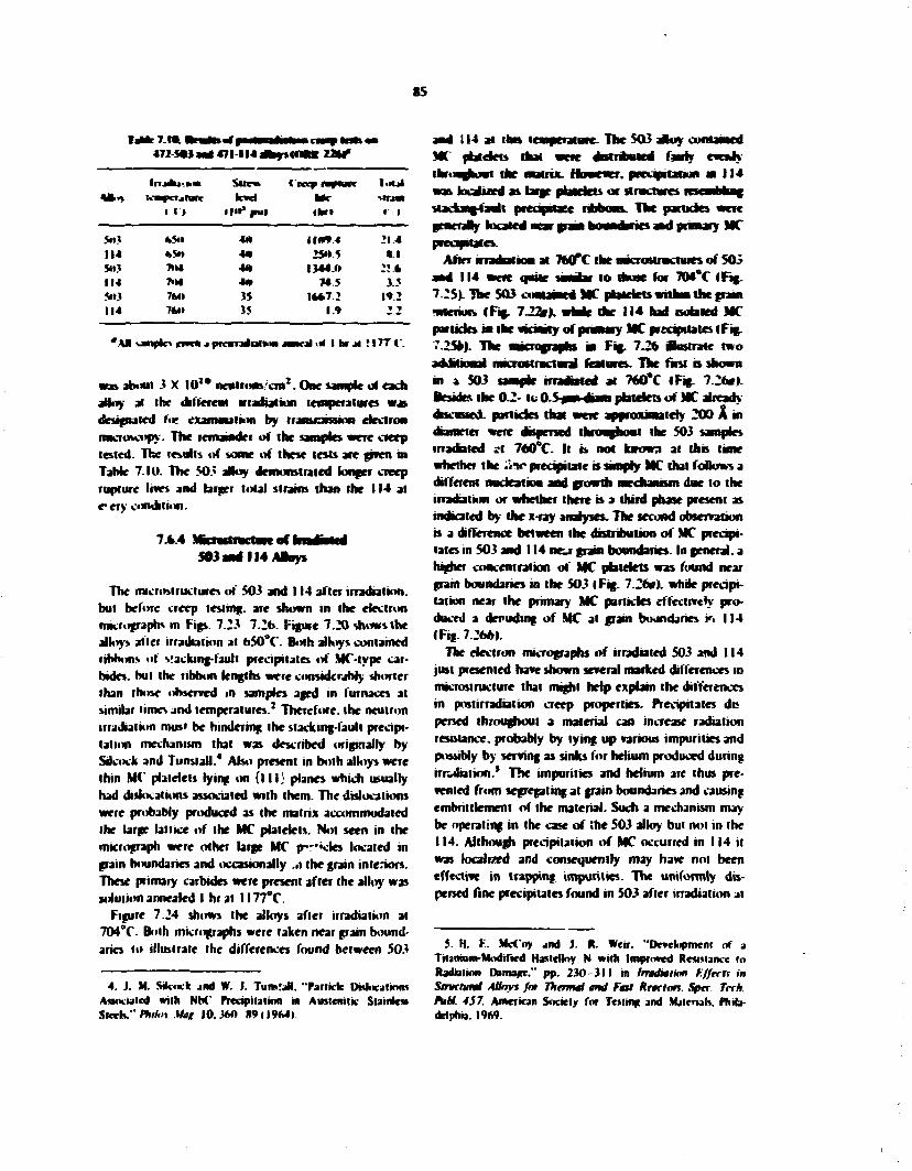
S5
k 7 . M i l 472-Sw) awj 471-114 a k w s t O U t 2 2 W
I I » IM** put
Creep i f M L M r ihr»
Mriai • l
5»J fc$ll 4(1 IIWV.4 214 114 *$» 40 2S»5 * . l S») 71 ki 40 1344.0 : ? * 114 7>M 4M 74.5 3.5 5«IJ 76M 3S l **7.2 19.2 114 7H» 35 1.9 » »
* * • vimpto ene* J p r a m d u t * * J — C J I <.* I far . * f 177 (".
was about 3 X I 0 1 * neutrons/cm2. One sample of each ahoy at ihe different irradiation temperatures was designated f«s exaimnalion by transraissinn electron microscopy. The remainder of the samples were creep tested. The results of some of these tests are given in TaMe 7.10. The 503 alloy demonstrated longer creep rupture Irves and larger total strains than the 114 at e"ery condition.
7.*.4 503 J
of 114 Aloys
The rracriistiiKtwes of 503 and 114 after irradiation, but before creep testing, arc shown in the electron micrograph* in Figs. 7.23 7.26. Figure 7.20 shows the alloy* alter irradiation at 650°C. Both alloys contained ribbons »l s!acking-fault precipitates of MC-type carbides, but the ribbon lengths were considerably shorter than those observed in samples aged in furnaces at similar time* and temperatures.2 Therefore, the neutron irradiation musi be hindering the siacking-faull precipitation mechanism that was described originally by Sovock and Tunstall.4 Abo present in both alloys were thin MC platelets lying on { I I I } planes which usually had dislocations associated with them. The dislocations were probably produced as the matrix accommodated the large lattice of the MC platelets. Not seen in the micrograph were other large MC p r i c k s located in grain boundaries and occasionally .it the grain interiors. These primary carbides were present after the alloy was solution annealed I hral I I77°C.
Figure 7.24 sh«rws the alloys after irradiation at 704°f. Both micrographs were taken near grain boundaries to illustrate ihe differences found between 503
4. j . M. Sik.uk and W. J. Turetall. "Particle DrdocalioRi Amxiated with N K ' Precipitation in Auslenitic Siaintc» $*xh." Phifai .V*g 10.360 H9 | I 9M»
and 114 at inn temperature. The 503 aftoy contained MC platelets that were drstribued fawty evcnly tbKNghowi the matrix. Hummer, pretaptatjun m 114 was lucalued as large pfewriets or structures tcsembbng Hacking fawlt pcetipame ribbons. The particles were generaly located near grain boundaries and pranary MC preapttafcs.
After irradation at 760*C the nacrostnKtwes of 503 and 114 were quite simlar to those for 704CC (Fig. 7.25). The 503 contained MC platelets withm the grant •nterwK f f ig . 722M). whne the 114 had rsofated MC particles m the ncai ty of primary MC precipitates (Fig. 7.25*). The micrographs m Fig. 7.26 Castrate two additional rmcroMructura) features. The first is shown in a 503 sample irradiated at 760*C I Fig. 7.26*>. Beside* the 0.2- to 0.5 m» mam pbldets of MC already discussed, particles that were approximately 200 A m diameter were dispersed throwgbout the 503 samples inadnted at 760°C. It b not torowa at this time whether the :ira» precipitate is shanty MC that follows a different nudeation and growth mechanrsm doe to the irradiation or whether there is a third phase present as indicated by the x-ray analyses. The second observation » a difference between the distribution of MC precipitates in 503 and 114 ne^r grain boundaries. In general, a higher concentration of MC platelets was found near grain boundaries in the 5031 Fig. 7.26»). while precipitation near the primary MC particles effectively produced a denuding of MC at grain boundaries in 114 (Fig. 7.266).
The electron micrographs of irradiated 503 and 114 just presented have shown several marked differences in rnicrostrucfurc that might help explain the differences in post irradiation creep properties. Precipitates dc persed throughout a material can increase radiation resistance, probably by lying up various impurities and possibly by serving as sinks for helium produced during irradiation.* The impurities and helium are thus prevented from segregating at grain boundaries and causing embrittlement of the material. Such a mechanism may be operating in the case of ;he 503 alloy but not in the 114. Although precipitation of MC occurred in 114 it was localized and consequently may haw not been effective in trapping impurities. The uniformly dispersed fine precipitates found in 503 after irradiation at
5. H. F.. McCoy and J. R. Weir. "Development of a Titanium-Modified Hastettoy N with Improved ResiMancc lo Radiation DBnure." pp. 230-311 in Irndtaikm Kffrcn in Structural Alloys for Thtrmti and Fmt Rcaclon. Spec Tech. PkH. 457. American Society for Testing and Materials. Philadelphia. 1969.

2. 3 i b 3
1
I m
i i
*

87
!
1 i
!
lb

88
2 8
fa
-8 5
1 1 3
"3
i E
si.
^ * " * • < • " . , » * #

89

90
760*C might also explain why the postirradution creep properties seem to improve with increasing irradiation temperature for that alloy. Whether the fine precipitate is a third p*>ase or a different morphology of MC. its presence could provide a more effective network of sites for trapping impurities and helium.
7.7 SALT CORROSION STUDIES
J. R. Keiser J. R. DiStefano
Several hundred thousand hours of corrosion experience have now been accumulated with Hastelloy N and fluoride salts in thermal-convection and forced-circulation systems. This experience has shown that in dean fluoride salts containing uranium the predominant corrosion mechanism is the leaching of chromium from Hastelloy N. Impurity fluorides such as F e F 2 , M o F 2 , and NiFj will also react with chromium to form C r F 2 . Water will react with the salt to form HF. which oxidizes all metallic components of the alloy. In tlie MSRE thv overall corrosion of IhsteUoy N was quite low during almost four years at temperature, attesting to the excellent corrosion resistance of this alloy in an actual system. However, operation of the MSRE also revealed that Hastelloy N was embrittled at grain boundaries due to interaction with fission products (probably tellurium) contained in the fuel salt. Subsequent studies have shown that certain chemical modifications improve the alloy's resistance to neutron irradiation and also increase its resistance to intergranular cracking by tellurium.
The experiments discussed in this section are being conducted to determine the corrosion behavior of regular and modified Hastelloy N as veil as other selected alloys in molten fluoride sails and to determine the effect of tellurium in the furl salt on the alloys. These corrosion experiments include the use of thermal-convection loops, a forced-circulation loop, and the Coolant-Salt Technology Facility.
7.7.1 Status of TlKniid-CowvectiM Loop P.
The facility for operation of thermal-convection loop tests is essentially complete. Two loop tests are currently in operation (Table 7.11) and six loop systems are under construction. Two ot' the six loop systems will use some components from previously operated systems ( I 8 B and 22A), while the other four will be completely new systems. All will Save provisions for dectrochemkai probe measurements to follow the U(IV)/U(I I I ) ratios of the circulating salt. Table 7.12
t » , UF-lrF.-lfcF.-UF, (72-16-11.7-0.3); c. 7WC; fcweiufH tftacMMl, 139*C
(hr)
21A 23
N M l
N M l
2295 721
TsMe 7.12 Tfccwnal luiwtiliuw loops vndet com Cm lion
Loop Loop material Specimen material Salt Objectives
I8B Hastelloy N Modified HasteBoy N MSBR fuel salt*
22A 316 stainless stcd 316 stainless sled MSBR fuel salt
24 Has'clloy N Modified Hastelloy N MSBR fuel salt
25 Hastclloy N Modified Haste!?oy N MSB* fuel salt
31 316 stainless steel 316 stainless steel LiF-Rcf-',
28 Ha«tclln> N Hastclloy N. modified Haslelloy N
MSBR coolant salt
Screening test loop for modified alloys
Determine if Fc-basc alloy can be used in fuel under MSBR conditions
Screening test loop for modified alloys
Te mass transfer studies and effect on mechanical properties
Analytical method development and baseline corrosion data
Analytical method development and baseline corrosion data
•LiF-BeF.-ThFVUF, (72-16-11.7-0.3 mole %).

91
gives a description of the six loop systems presently under construction.
7.7.2 M S * l t e m a l C * a M c t i M L M » Resales
The thermal-convection loop program is to (1) develop electrochemical methods for evaluation of corrosion data in molten salt systems, (2) study the behavior of tellurium in molten salt systems and determine its effect on potential MSBR containment materials, and (3) evaluate the corrosion resistance of Hastdloy N, modified Hastdloy N, and other potential containment materials to the MSBR fuel salt LiF-BeF2-ThFj-UF* (72-16-11.7-0.3 mole %).
Thermal-convection loop 23 is constructed of Inconel 601, a material which shows resistance to tellurium-induced gr.iin-boundary embrittkmen:. However, Inconel 601 has a high chromium content (23 wt %) and is mote susceptible to oxidation bj UF 4 than Hastdloy N. During initial operation of loop 23. electrochemical measurements were made at regular intervals, and after 721 hr, corrosion insert specimens were removed for examination. The results of the electrochemical measurements (Sect. 6.1) indicate that the U(iV)/U(lll) ratio dropped rapidly after the salt was put into the loop. The U(IV)/U(lll; ratio was initially above I0 4 , but after IS min it was 200, and after six days it was 40. A short time before the specimens were removed, the ratio had decreased to about 20. A decrease in the U(iV)/U(lll) ratio of this magnitude implied that extensive corrosion had occurred. Examination of the removable specimens verified that the corrosion rate was indeed hign. All the specimens that were in the salt lost weight; those in the hottest positions lost nearly \% of their initial weight. Weight loss as a function of temperature and location is shown in Fig. 7.27. Because of a malfunction of the heaters, the temperature of the lower portion of the hot leg was higher than the design temperature for a short time. Consequently, the weight losses oi specimens in the lower portion of the hot leg are probably greater than would have been the case if no malfunction had occurred. (These points are not plotted in Fig. 7.27.)
Thermal-convection loop 21A is a Haslelloy N loop which had been previously operated before the MSR Program vra terminated in early 1973. The loop has been restarted with new specimens and fresh MSBR fuel sali. The U(IV)/U(III) ratio in this loop has remained at a relatively high level. After one day of salt circulation, UOWUOII) was 1.2 X 10 s , after II days it was 5 X I 0 4 , and after 45 days it had only decreased (n about 1.5 X 10 4 . indicating that the corrosion rate was fairly
low. Insert specimens were examined after 2760 hi. Four specimens in the hottest portion of the loop lost weight, while all others gained weight. Weight change as function of temperature and position in the loop is shown in (Fig, 12%).
A comparison of Figs. 7.27 and 7.28 shows that Inconel 601 is corroding more rapidly than HasteUoy N. More serious attack of the Inconel 601 would have occurred if the U(IVyU(III) ratio had been mainia- ed in the range of I 0 : - S to 10*- 1 , as presently considered appropriate for an MSBR.* Therefore the compatibility of ln;onel 601 with MSBR fuel salt does not appear adequate for service at the present7 design temperature.
7 .73 FotceJ-CaTuhliun Loop Results
HasteUoy N forced-circulation loop FCL-2b completed preliminary operations near the end of October 1974. During this period, the loop contained MSRE fuel salt LiF-BcF,-ThF4-UF4 (68-20-11.7-0.3 mole %) and operated isothermaliy for ail but the last week. Operation was interrupted by ?n oil leak and was resumed in January 1975 (Sect. 2.4).
During the preliminary operational period, Hastelloy N metallurgical insert specimens were removed twice, once in early September after six beryllium additions had been made to the fuel salt and a second time near the end of October, after three NiFj additions had been made. The beryllium additions made the salt less oxidizing by lowering the U(IV)/U(III) ratio, while the NiF, additions raised the U(l")/U(lll) ratio and made the salt more oxidizing. Consequently, the corrosion rate was expected to be very low during the first period and somewhat higher during the latter period. Results are given in Table 7.13.
During the first period, when the salt had a low U(IV)/U(III) ratio and operation was isothermal, weight losses and corrosion rates were low, as expected. During the second period of preliminary operation, the U(IV)/(J(III) ratio was much higher, and, in addition, there was a!39°C (250°F) temperature gradient imposed on the loop for part of the period. Consequently, the maximum weight loss and attendant corrosion rates were higher than during the first period. Data obtained during the preliminary period showed that changes in the oxidation potential of the salt could
6. C. I. Bats, it., R. P. Wtchncr, C. f. Bamberger, and B. h. VteasKT. lo be published in Nuclear Science and Knfineerinf.
7. ftofftm Flan far Development of Molten Salt Breeder Reactor*. ORNI.-5018 (December 1974).

92
ORNl- 0«C 75- 4«2a*>
«?• « r ^ * TEMPERATURE C O
& «,* J>
u, . 3 «9 Z 4 I o I-I o w *
^ ^ 1 1 1 1
COLO LEG HOT LEG (VERTICAL) 1 (VERTICAL)
i* >
•
» »
t i
| |
i i i i 1
\ e )
•
<
/
»/
i
i i i i i ! f
j
i
• 1 •
f # £ <? . * p ,•? „# v«p rfp J? J> TEMPERATURE (*F)
F«. 7.27. Wejrfit chmft M a function of temperature for iMond M l exposaif to MSRR fml aril n ThcimalCom>aclkm Loop 23 after 721 Mr.
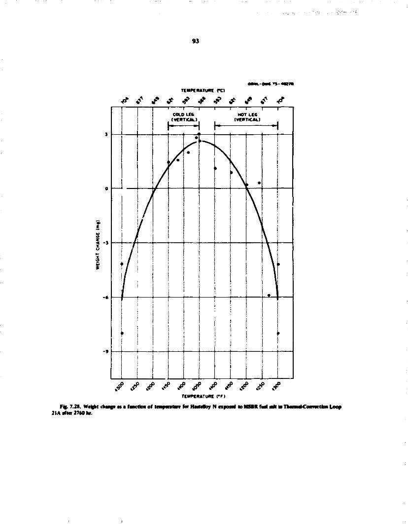
93
oawL-oac *s-4«ni TEMPERATURE 1X1
J S S # # . < * # f £ 4? i
COLO LEG (VERTICAL) \m
! 1 HOT LEG
(VERTICAL)
3 ' 1 "
3 • • • - W 1
i Y
•
^ \ 0
M \ k • 0 I '
w «9 5 - 3 X u
w «9 5 - 3 X u i j
j \
WEI
GHT
1 / f/ \ l
i ! ! ! !
1
\
-6
-9
1 1 • -6
-9
»
i . . . . _ i 1 1
>
/ # # # # # f f # # / TEMPERATURE (*F)
F t 7.28. Weight ditRgc as a fMctioii of lemptntar* lot Haatdoy N expos*! to MSM t M aft at TheiiRatCoRvacfiDR I 2IA after 2760 kr.

94
Tin* Wriffct km Coiran mc* Knot t u u l ( • ! « ' year'). tanWyca).
<hr) a a rai
1 2330 0.2 0.01 2 . -"•* 2-» 0.12
3 « t 2.7 0.12
be followed dectruchernicaRy and could be correlated with weight-change measure me nts.
Dunng the next period. FCL-2b was operated under conditions designed to gather baseline corrosion data using MSBR fuel salt LiF-BeF j-ThF 4-UF« (72-16-11.7-0.3 mole %). The specimens were examined after one month's exposure (Table 7.13). Because this exposure was almost entirely under the MSBR reference-design operating conditions of 704*C (I300*F) maximum temperature and I39*C (2S0*F) temperature differential, corrosion rates were higher than during the earlier periods of isothermal operation, when there was no contribution from mass transfer. However, corrosion rates remained wdl within acceptable limits.
7.7.4 Cdofant-Salt Technology FadVty Results
The Coolant-Salt Technology Facility has provisions for exposing three metallurgical specimens to high-velocity NaBF 4NaF |92-8 mole 1) coolant salt. During this reporting period, three Hastelloy N specimens were exposed for a ten-day period. When the specimen holder was removed from the m i facility, one of the specimens was missing, and another was damaged during removal from the hotder Examination of the third specimen showed that its surface had been scratched. Salt was observed in the scratches by microscopic examination, which indicates that the specimen was damaged prior to exposure or. possibly, as a result of abrasion by the missing specimen.
Both of the recovered specimens showed weight losses, but these losses reflect other effects in addition to corrosion of the specimens by the fluoroborale salt. Assuming lhal all weight lest was material that was removed uniformly, the material removal rale was
almost I mil/year. However, because some material was lost by muhinkal means, this rate overestimates die true corrosion rate.
The next experiment to be performed in this taatky wdl make use of a different rptumen holder designed to prevent loss of specimens from rhe holder.
7.73 SmarrVt Tests
A series of experiment] is planned using thermal-cmvccuon and torced-vircvJation loops to study mass transport of teHu.ium in fuel salt and its effect on the ductility of the containment material. However, a method must be developed that will effectively simulate the production of tenwrinm in fuel salt as it occurs under reactor conditions. Several methods for adding letturium have been proposed, and two test vessels are being constructed to evaluate the various methods. The first vessel ww have viewmg ports, electrochemical probes, and accesses for stirring, sampling, or making additions. Pellets containing measured amounts of lithium idluride will be added to the salt to simuble production of tellurium. The second vessel wifl have dccirocherrical probes and accesses for stirring and sampling and wiB use nickd or chromium teBuride for supplying tellurium to the salt.
7 .8 CORROSION OF HASTELLOY N AND OTHER ALLOYS IN STEAM
B. McNabb II E. McCoy
The corrosion of standard and modified Hastelloy N and other iron-, nickd-. and cobalt-base alloys is being evaluated in steam at 53ft*C in TV As Bull Run Steam Plant. Unstressed sheet specimens 2 in. long. '/, in. wide, and 0.03S in. thick have been exposed tc flowing steam (appro* 1000 Ib'hrl for up to 17.000 hr. Weight changes and observations have been reported previously* for 15000 hr exposure, and the same trends are continuing with increased exposure.
One material of considerable metallurgical interest was type 201 stainless sled. This material, when 507 cold worked, had markedly lower weight pins in the cold-worked cimduion than in the annealed condition. After 6000 hr exposure the cold-worked specimens had average weight gains of 0.146 mg/cm z. X-ray diffraction patterns were made from the oxides on two of
H. H. fv. M.-Coy and B. McNahb. Cotmkm of Srrrrrt Iron ami MckrIBaw Alloyt in Supmritiral Steam at ItHHfF. ORNI TM-4352 (Aueinl 19741.

95
these specimens . and the specimens were returned lu the Bull Run facility tut additional exposure. Preiaw-nary analysis indicates that the annealed specimen I No. 353) formed oxides of F c j 0 4 and a-Fe>0, sufficiently truck thai no matrix peaks were delected- These data .-•*! *ome additional information on coutroi specimens arc ,f.vn in Table 7.14. The cold-worked specimen (No. 354| had a (body centered cubic) matrix (strong intensity) with a lattice parameter of 2.878 ± 0X102 A. which could correspond to an Fe-60% chromium lerritic alloy. Some (face centered cubic) pLtse (weak intensity I with a lattice parameter of 3.594 * was present, indicating that the transformation ol the matrix from tec to bec must be rather sluggiii not to have been completed in 6000 hr at 538°C. The oxide layer consisted of M n F e 2 0 4 (medium) and a-FejOj (weak). The matrix lines dominated the pattern, indicating that the oxide was thin. This was also indicated by interference colors still visible in the oxide layer. A coid-woiked specimen which had been oxidized 4000 hr in a." I No. 422. 117 nig. cm 2 ) also had the same strong bec matrix with a lattice parameter of 2.875 A and oxides M n F e 2 0 4 (medium). (Mn.Fe)jOj (weak), and e -Fe j0 3 (very weak), which accounted for most of the lines in the x-ray pattern. There was slightly more of the fee matrix |3.5*>1 t 0.003 A) present in this
9. O. B. Carin. ORNL. private c-ommunicalion-
specimen than in the one exposed to steam. The lower exposure 'one (4000 hr vs 6000 hr» probably accounts f«r rhis. since the iransformation lo bec ferrite at this temperature ( 5 3 8 X ) appears sluggish. Annealed and cold-worked samples which had not been exposed to high temperature (538°C) had tec (austenite) matrix with a lattice parameter of 3.598 A- The transformation to bec from fee under the influence of cold work and annealing is not completely understood, but this is being investigated.
The effect of stress on the compatibility of HasteUoy N in steam is being evaluated by tube-burst-type specimens using the 3500-psjg steam pressure and varying wall thickness to obtain the desired stress on the specimens. A double-walled tube arrangemen; is being used with the annulus between the tubes connected by a capillary tube to the condenser. When rupture of the inner tube occurs, steam passes through the capillary tube and is sensed by a thermocouple attached to the capillary tube. Thermocouples from the ten instrumented tube-burst specimens are connected to a multipoint recorder, and a temperature increase indicates rupture of a specimen.
Two heats of standard Hastefloy N. N15095 and N25IOI . have been tested in argon and in steam. The tests in argon used that gas as the pressurizing medium and as a cover gas over Ihe outside of the specimen. The reduced-wali-section specimens were identical in geom-
Tabk 7.14. ReaaMs of x-ray statics of type 201
Fxpoture conditions
X-ray Mfomaiion Specimen
no. Fxpoture conditions Matrix
Larrice
Oxide Fxpoture conditions
Structure Intensity Larrice Identification Intensity parameter
IA)
353 Annealed 1 hr at |05(fC in argon, annralrd 600 hr at 538°C in steam
Fe.O. oFe,0, 4 unidentified
peak*
Strang Wean Very weak
354 Cold worked 50%. annealed 6000 hr at 538°C in *team
Bec
Fee
Strong
Weak
2.S78 3.594
M*Fc,0, o-¥t,0, Several unidentified peaks
Weak Weak
422 Cold worked StrV. annealed 4000 hr at 53fr°Cinair
Bee
Fee
Strong
Weak
2.S75 3.591
M*Fe,0, M»Fe,0, o-Fe.O,
Median Weak Very weak
Annealed Annealed 1 hr at I050*C in argon
Fee Strong (strain free)
3.5975
Cold Worked Cold worked 5 0 * Fee Strong (line broadening)
3.59
%
etry to those tested in steam except that the argon test specimens had plugs welded m each en;J with one plug having a capSary tube connected to an argon supply tor pmsurumg- The specimen geometry used in steam has been detaned previously.'*
The stress-rupture properties of heal M5CH5 are shown m Fit- 7.2*». As discussed previously." flaws in some specimens probably contributed significantly to the scatter in the data both in argon and in steam-There appears to be some effect of the steam only at higher stresses and shorter limes. These data w ' e obtained before ultrasonic inspection of the specimens was instituted. A number of tests are stiU in progress as indicated by the arrows in Fig. 7.**: the specimens in argon and steam environments appear to have equivalent rupture times. This indicates that under these conditions steam does not shorten the rupture life ot rbstelloy Mheat \ I 5 * » 5 »
Figure 7.30 shows the stress-rupture properties of heat N25101. All of the annealed, highly stressed specimens tested in steam had shorter rupture times than those tested in argon. These test specimens were not ultrasonically inspected, so it is not known if they had flaws. Specimens that were inspected and tested in steam in the "as received" condition appear to have
IA ft. McHabb a*« H. E. McCoy. MSK fmgimm S n w m ftoxr. Rep. Am* SI. 19?;. OHNL4X3 ' . pp J 37 46.
rupture times equivalent to those of specimens tested in argon. Several are stdl in test, as indicated by the arrows in Fig. 7.30. Annealed specimens that have been uttrasonicaMy inspected will be tested to determine if there is an effect of cold work or pretest annealing on the rupture life of stressed specimens. There appears to be no eftect of cold work on weight gains of unstressed specimens of Hasteloy N.
At 538°C the fracture mode of Hastetioy N can be shifted very easily from intergranular to transgranubr. Thus it is not too surprising that the fracture appearances are rather randomly distributed between inter-granular and transgranular modes regardkss of rupture time and test environment. Figure 7.31 shows photomicrographs of the fractures of Hastefloy N heat NI50°5 tube-burst specimens tested at 538°C in steam in the as-received or as-machined condition. Specimen a was stressed at bo.000 psi: it ruptured at 4.0 hr with a ductile fracture. Specimen h was stressed at 40.400 psi: it ruptured at 2088.8 hr (approximately half the normal rupture life! with a brittle fracture. Specimen <- was stressed at 53.200 psi. it ruptured ytween 5000 and f»000 hr with a ductile fracture, ihe cracks in the outside surface of the lube and deformation at the outside eJge of the fracture were caused by the impact of the stressed lube at rupture with the outside tube of the double-walled specimen. The 3500-psig steam pressure was on the inside of the stressed tube.
90 r-0MK.-OBG n-TiOi
?0 i •<>
m 60
5, *>?
AS- AIWNEALE0 I nr «CC£lVE0 AT||77«C
ARGON o O STEAM • •
T>»f> O C CD
40
»
»i-Fin. 7.». m*
K>' ' 0 * «0* 10* * U » * l * C r « K (*r)
H Mm msmtt. Tnfcn Mwrnd m *%<m and
•0»
latsirr.

97
90
to
TO
o o
OMML-IMS T S - T t O I
AS- ANNEALED t M — BECC'WCO AT »I77«C
5«o
so
40
30
MOON a STEAM •
- * -
10°
F » 7 J n . Raf tMCMkof
10* l O 1 10 s
RUPTURE TME (»r>
N<HmN25l«l>.T a
W 5
i « 5 3 r r
Figure 732 shows photomicrographs of the fractures of Hasteiloy N heat N15095 tube-burst specimens tested in the annealed condition ( I hr at I I77°C> in sier.m at 5 3 8 T . Specimen a was stressed at 64X100 psi: it ruptured in 28.8 hr with a ductile fracture. Specimen b was stressed at 5 ° 3 0 0 psi: it ruptured in 75 J hr with a ductile fracture. Specimen r was stressed at 55.500 psi: it ruptured in 1443 hr with a ductile fracture. These specimens had considerable deformation at the outside of the fracture caused by impacting the outside tube at rupture. This ability to deform indicates that the material was not embrittled by the exposure to steam.
Figure 7.33 shows photomicrographs of HasteUoy N heal N25IOI tube-burst specimens listed m the as-received condition at 538°C in steam. Specimen «. stressed ai 71.300 psi. ruptured in 5.1 hr: specimen b. stressed at 70jOOO psi. ruptured in 174J hr: and specimen r. stressed at 56.000 psi. ruptured in 5000 to 6000 hr. Specimen r. which was not an instrumented specimen, had not failed when inspected at 5000 hr. but had failed when inspected at 6000 hr. The cracks on the outside surface of each tube were caused by the impact of the stressed inner lube with the outer tube of the double lube specimen. All three of these specimens tested m steam appear to have ductile fractures and to have rupture times equivalent I O or greater than those of specimens tested in argon. In fact, specimen c had a longer rupture time than a similar test in argon which was stressed at 55X100 psi and ruptured in 1525.8 hr.
Figure 7.34 shows the fractures of Hssldloy N heal N25IOI lube-burst specimens tested in the annealed
condition ( ! hr at 1177°0 in steam at 538°C. Specimen a was stressed at 70X100 psi. it ruptured in I J hr with a ductile-type fracture and considerable deformation of the outside of the fracture on impact with the outside wall. Photomicrograph* b and c were m»1e of a specimen stressed at 56300 psi that ruptured in 19.5 hr with a brittle fracture. An area away from the primary fracture a shown in c. The reason t V these variable test results is not presently known.
As reported previously.1 • some specimens trsied in argon ruptured prematurely and exhibited sonv cracking on both the inside and the outside of the specimen wall. All of the specimens tested in steam in the annealed condition ( i hr at 1 1 7 7 ° 0 ruptured at shorter times than similar stressed specimens tested in argon. The annealed series of specimens had not been ultra-sonkally inspected before testing, so they could possibly have contained some flaws. However, it is unlikely that all of them would have contained flaws. The very similar heal N15095 in the annealed condition had ductile failures (Fig. 132). In both heals the specimens were machined, annealed I hr at I I77°C. t',cn welded into the doubie-waBed specimen geometry before testing. As far as is known, the same cleaning procedures were used before welding (thorough degreasmg in acetone>. but different welding facilities were used in the fabrication of the specimens. The annealed specimens (N2S10! ) were fabricated by outside vendors, the others were fabricated by ORNL personnel. Other specimens will be prepared with clow control over these variables to resolve the differences.

98
lOO 2 0 0 MICRONS | « - | « — | — ' fOOX 600 700
* -H — I — " r 0005 0.0*0 INCHES O.020 0.025
SO IQO MtCRONS 3Q0 350 > T t i \ I S—?00X—•» , V i *r T <
0 004 INCHCS 0.010 0015
Fa> 7..M. rfculiiaJiiiiajiaaHi of * » fractam of llamOuj N i H m NISM»> I toajiWaa m mam af SJTC. <J» Strcwd J I a* JMO Mi jad ruptured in 4» hr. A* pohdwd lOOx. <»> Suaaad) ai 49*00 a* mi ruanavd m 21** > kt. Eidwd wiia ftycern rexb IflOx <c> Sirraed J I 5 JJiW pit and ntplarad at 5000 lo 44100 at. beard mim iriycam !••». 200x. Kafcfd 19*.

99
too 20b -*-r—"
0 0 0 5
. _ _ - «00 700 * r-" K»» »| * - | * 1-1
0.0W -HCMC5 0.020 0 0 2 9
SO IOC WXMOMS SOO 390 \ I T I T I S 2O0» V—r-V—r-V-r
0 0 0 5 IMCHCS 0010 OO 0015
hf at 1177*0. u» SIWMMI at MJOOO p«. nartaml al 2tS kr. lOOx (b| Slitmei af WJOO pw. rapfarcd al 75.) hf. lOOx. <c» Simat* at 55 JflO pN. rapiMcrf M 1443 kr. 20Bx. Al ipu ww welched with grycrra rqpo. ROMMMI 7*».
100
SO IQO MICRONS 300 35C 1 I I I V I S 200X_ _ l | _ i T I 'l 0.005 INCHES O.OfO 0.015
100 200 MICRONS «00 700 | I , I • I t 0 0 X — * , • , " | |
0005 OOIO INCHES 0.020 0.025
Ffc.7.1). Thommhtoptfks of HaUdtoy > Heal Mi 101 luut hwnt yecimem tend in »e "asrccemd" coadtfiD* a45JTC in MOM. lal Strewed at 7l.3«Klp«. rupiured in $.1 hr. 2'IOy. (hi Strewed at 70.000 psi. ruptured in 174 J hr. 2W)X. t o Sfreued at if,.nm pM. rupiured in 5000 to 6000 hr. I00x. F.uhcd in ejycrru reeia. Reduced IR%.
101
(* ) 50 IQO
I • \ • V t MICRONS 9 0 0 3 5 0
• + — 2 0 0 X 'i i ' l I ' i I < 0.015 0.005 INCHES O.01O
100 2 0 0
0.035 0. 6*0 MICRONS
— IOOX— 600 700
1 ' I ' I ( INCHES 0.020 0.025
F^. 7.34. PlMlMiicTCynBjif of vto fncflNfvsof Mfflcflvy PI Htvf !V25101 Mtv-vvm ^vnntns lovvJ in •" ( I w»M l)7rOtos«HMl»tSJft*C.lj>!lircacdal 7n.fflin mi. rapf arcd in l.'hr F.fchrd villi jrfyrcriJ refn. Mnv. lb.cl Strewed JI 5»-5fl»p*i. mpfarcd in 19.5 hr. A* pnhdifd. innx.

102
7.9 DEVELOPMENT OF A TELLURIUM-DELIVERY SYSTEM FOR
A REPRESENTATIVE TELLURIUM-CORROSION SCREENING TEST METHOD
J. Brynestad
Several factors are important to the development of a good tellurium corrosion screening test system for study of tellurium-induced intergranular cracking. The test system must expose the test specimens to a tellurium level that exceeds that encountered at any vulnerable place in the MSBR. and in such ? way that the test results can be used to predict the materials' behavior under MSBR conditions. On the other hand, the exposure level should not be unreasonably high.
At this stage, the tellurium exposure level in an MSBR is not defined. Although it is possible to estimate the total amount of tellurium produced during the life-span of an MSBR. the activity of the tellurium is not defined. However, one must assume that a considerable part of the tellurium that contacts the alloy will be in a highly activated state, whereas the remainder will react with the melt and assume the redox state imposed by the melt. The kinetics of all these reactions are unknown.
The test system must be reproducible: that is. it .nust expose all specimens in the same way. The duration of the test must be relatively short as compared with the lifetime of an MSBR without violating the first requirement. The system ought to be reliable ard relatively simple to operate.
Among these requirements, the tellurium exposure level is the most nebulous one. At present, it is not known what telluridei. if any. were formed with llastelloy N in the MSRE. However, it is known that tellurium can cause intergrar.ular cmbrittlement of nickel at low chemical activities.
To obtain more information about tellurium-induced inte.granular attack of Hastelloy at different tellurium activities, three different nickel-:ellurium equilibrium systems were prepared with different, but lime-constant, tellurium activities:
1. NiiTejI^jXs)* Ni(s)(low tellurium activity). 1 Ni |Te ; , , (0 j Ks> • NiTe0 TTJTI KS) (medium tellu
rium activ'ty). and .? NiTc„ »«(7, Ks> + NiTe, o g (6KsMhigh tellurium
activity).
The designations of the nickel-fellurium phases arc the same as used by Klepp and Komarek.'' Of these systems, system I should bo unable to form any n* •••'•'
tcUuride on Hastelloy N by isothermal interaction, since the activity of nickel in this system equals I. whereas the activity of nickel in Hastelloy N is less than 1. Three different compositions of Hastelloy N tensile specimens were embedded in each of these granulated mixtures in evacuated and sealed silica capsules and were treated for 2O0hrat7O0#C.
The high-teilurium-activity system did in fact have too high tellurium activity, since it almost completely destroyed the samples. The low-tellurium-activity system had little effect on the specimens, indicating that the activity indeed is too low. or that the exposure time was too short. The medium-teUuriurn-activity system showed considerable attack on the specimens, more than desired for a screening test.
To test further, systems I and 2 were retested using system I at 700"C for 1000 hr and system 2 at 6S0"C for 250 hr. Again, the medium tellurium activity was quite active, whereas the low tellurium activity was substantially less.
It appears that a tellurium activity somewhere between those of systems I and 2 may prove to be most like that actually in an MSBR. The system CrjTe,-Cr)Te4 is such a system, and experiments are in progress to obtain more information.
7.10 REACTIONS OF TELLURIUM WITH NICKEL AT LOW TELLURIUM ACTIVITIES
J. Brynestad R. E. Clausing
It is important to obtain meaningful, basic information concerning the nature of the grain-boundary products or "surface compounds"1 2 which give rise to intergranular embrittlement. Necessary steps toward this goal are information abojt the equilibrium distribution of tellurium between the bulk phase of the metal and the grain boundaries, about the relative stabilities of the "surface compounds" vs the regular (bulk) tcHuridcs. and about the tellurium activity levels at
11. K. O. Klepp and K. L. Komarek. Mor.itOi. Otem. 103. 934 46(1972).
12. The :erm "surface compounds" is introduced (<> apply specifically to surface (jrain boundary or free v.rfatc) products which are formed when tellurium mo r.ctals arc reacted. Although compounds or phases commonly refer lo hulk phases. Ihis concept has developed simply hr^iusc of our inability to delect compound formation on a smaller seal;. Grain boundaries have properties different from those of the hulk material and would he expected to react diffcrcntlv chemically. The development of analytical tools such as Auger spectroscopy fiives the capability to characterize the reaction products contained within the grain boundary.

103
which the surface compounds are formed. The nickel -leilurium system was chosen for preliminary study.
In the experiment a I .5-mil-thkk nickel foil about I cm wide and 4 cm long was exposed for 2500 hr *u tellurium vapor at W0°C I lower end) to 1005'f (upper end). The tellurium vapor was delivered from the equilibrium system Nits) + j j , -Ni telluridefs) (VJ7 at. '> Te). whkh was kept at "^)80*C which is a lower temperature than that of any point on the foil. The whole system was contained in an evacuated, sealed silka capsule. Since 0,-Ki telluride is the most nickel-rich telluride in the nkkei-te!lurium system at these temperatures, this setup ensured thai the nickel foil could not react as to form any bulk nkkel telluride. but could only f<-rm solid sot.ttions of tellurium in nickel and surface compounds. Attc equilibration for 2500 hr. the system was removed :.om the furnace and air-cooled.
The foil was visibly dt formed and quite brittle. A piece of the foil was investigated by x-ray analysis. No bulk nkkel tellurides were detectable. The lattice parameter of the nickel was found to be 3.5272 ± 0.0002 A | 2 0 ° O . as compared with Jette and Foote*s M value of 3.523'M A (25°C>. indkating a slight lattice expansion. (A control thermal test of unexposed nickel foil is being done.)
Chemical analysis of a piece of the toil gave an overall content of 0.25 at. ''< of tellurium. A piece of the sample was investigated by Auger spectroscopy using a newly acquired high-resolution, small-area Auger spectrometer with a beam si/e of <5 p. Both surface and grain-boundary areas were examined, and both showed tellurium concentrations of about 10 at. "r (when normalised to Tr Ni + 1r Te = 100%). No corrections have yet been made for chemical effects on the nickel spectra or the inhomogencous distribution of tellurium with depth. Neither of these corrections can be made satisfactorily until special standardization techniques have been established. Probably, both corrections will increase the measured tellurium concentration, with the combined effect that the tellurium concentrations may be double the reported values. Sputtering the surface and grain-boundary regions to a depth of about 10 A reduced the tellurium concentration by about 75'* and 85%. respectively, and sputtering to about 100 A reduced the tellurium concentration to about I at. % on the surface and to £0.2 at. '"r in the grain-boundary region
13. Jclicand l-'ootr.Stniklurhrrirhlr i. 187 (I93M.
Strong chemical effects were seen in the nickel Auger spectra These complicate the present analysis but offer a potential method for identifying compounds by the nature of the chemical bond formed-
These results indkate that tellurium has a strong tendency for surface-compound formation on grain boundaries in nickel, with a distribution ratio £ 100 for the distribution of tellurium between the grain-boundary phase and thf bulk phase. This indicates, in the case of nkkel. that tellurium vapor can embrittie nkkel by intergranular surface-compound formation at pressures that are much lower than those required for the formation of bulk nkkel tellurides. The question remains as to what extent this also holds true in the case of Hastelloy N. Most probably, the distribution ratios of the alloying constituents in Hastelioy N between bulk and grain boundaries are not unity. Therefore, depending upon this distribution and upon the properties of the various surface-compound tellurites, a given alloy composition may be embrittled by tellurium more or less than pure nickel. The tellurides of chromium and titanium are thermodynamically more stable than the nkkel tellurides. as are also somr ternary compounds (nickel-titanium tellurides). and t might seem plausible to assume that the same wouli apply to surface-compound telluridns. so that surface compound tellurides in Hastelloy N would be expected to be more stable than those in pure nickel. However. the stability of an intergranular surface compound must be measured relative to the stabilities of vhe possible bulk nvtal teilurides and to solid-solution-type structural units. If an alloying constituent causes a shift in the relative stabilities of surface-compound telluride formation vs regular bulk telluride formation, the constituent could prevent intergranular embriMlmwl. although at the expense of increased corrosion by bulk telluridc formation. However, this would represent an advantage in an MSBR. where the total amo'int of tellurium produced is very small.
A serious obstacle in this work is the fact that our understanding of intcrgranular surface compounds in general is still very limited. Largely unknown are the nature and strength of bonding, thickness, and structures as a function of the nature of the grain boundaries (low angle, high angle). Also, only limited analytical took and methods arc as yet available for attacking these problems. However, a coordinated study involving Auger spectroscopy, low-energy electron diffraction, electron spectroscopy for chemical analysis, electron microscopy, x-ray analysis, and thermodynamic and chemical methods certainly bear the promise of significant gains in this area.

104
7.11 SURFACE ANDGRAIN-KHJNDARY STUDIES RELATED TO HASTELLOY N GRA1N40UNDARY EMtRITTLEMEMT
R. E. Clausing L Hratherly
Auger electron spectroscop>' and other new surfacc-sensiim techniques are being applied to study the grain-boundary embrittlcment of Kastelloy N which was observed in some specimens removed from the MSRE. This effort is intended to (I) confirm that tellurium was indeed present in the grain boundaries of samples removed from the MSRE in amounts sufficient to cause the observed embrittlement. (2) examine samples prepared in various screening tests to determine the nature and extent of grain-boundary and surface reactions of various alloys with tellurium. (3) study in detail specially prepared materials designed to help understand the mechanisms, chemistry, and metallurgy of this form of grain-boundary embrittlement. (4) determine the equilibrium partition of tellurium between bulk, surface, and grain boundaries in nickel. Hasteiloy N. and modified Hastelloy N. and (5) explore the use of high-temperature in situ Auger electron spectroscopy for rapid and direct screening of alloys for resbtance to tellurium attack. Items 1. \ and 3 depend heavily en the availability of the high-performance Auger spectrometer described below. Accordingly, most emphasb b on thb effort. The spectrometer b now in operation, and data are being obtained on a regular basis. The continuing development of supporting equipment (especially for data acquisition and handling) will increase the usefulness of the spectrometer.
The iquipment is being continually improved for in situ high-temperature studies: some data recently obtained using thb technique are reported in Sect. 7.11.2. Presently under study is the diffusion ot tellurium, sulfur, and carbon to the surface of several samples prepared from the shoulders of tensile samples made from alloys containing tellurium. Data obtained in a few hours with thb technique can provide information on the partition of tellurium between the hulk and surface of a sample and on the rate of diffusion of tellurium to the surface. A tellurium evaporator has been designed for use with the high-temperature equipment so that the inward diffusion of tellurium from the surface of an alloy may be studied in an experiment which is more or less the inverse of the above experiment. Thb new experiment will provide information on the penetration of tellurium into grain boundaries and bulk material from the surface as a function of time, temperature, and alloy content.
Construction and use of this equipment are not presently proceeding because of budget limitations.
7 H . I D i u l i | i i M a f l T w w 4 T > r h B i i > i j
An apparatus developed to provide Auger electron spectroscopic analysis of areas as small as 5 u in diameter b operating satisfactorily. This provides the ability to analyze surfaces and grain-boundary fracture surfaces in great detail. The small-diameter electron beam used for anah as b rastered to produce a scanning electron microscope type of display (using absorbed sample current) at a magnifkatron of several hundred times the actual size, and car. position the beam on selected spots for complete elemental analysis. The analysb b nondestructive, and as many points as desired may be analyzed fo> all elements except hydrogen and helium. Auger iajnals ate obtained only front the first few atom layers of the exposed surface. These surface layers can be removed by sputtering to expose successive depths for analysb. so that we may determine composition as a function of distance below the original surface and therefore the distribution of elements in and near the embrittled grain boundaries.
The analysis of a thin nickel foil embrittled with tellurium and fractured to expose the grain boundaries (Sect. 7.i0) illustrates an application of the new equipment in a situation wh'.. the older apparatus would not have provided satbfactory results.
7 .112 r^h Temperature Studies »f the Behavior of Tefcriwa in and on ExperinKafaJ Afloys
Thb work has been given less priority than the work with the small-diameter beam: nevertheless, several recent runs have been made with tellurium-doped Hastelloy N heats 359 (7% Cr) and 361 « l%Cr) . The compositions of these alloys are given in Table 7.IS.
The most significant results thus far are thai these alloys both appear to have about 2.5 at. % tellurium and 10 to 15 at." ..uiiur on their surfaces in vacuum at
TaMc 7.15. CompoMiom of nturium aoptd Hastcfcy N-rrpe afers
In wcght percent
Heal Mo Cr Fe Mn Si Te S
359 361
14.3 I5.R
<-i.o 6.75
3.3 4.35
0.6 0.5
0.45 0.46
0.04 0.06
0.002* 0.002
"Estimated level.
105
700"C. This represenU a M-rface enrichment over the but* of about 4000 for sulfur and about 100 for tellurium- The tellurium surface-enrichment factor in these aSoys is similar to that reported in the previous section for tellurium in nickel at 1000*C. Because of the differences in temperature, alloy content, sulfur levels, and exposure conditions, this result is interesting and worthy of further investigation but does not allow a direct comparison. Additional nickel samples prepared at lower temperatures vriB be examined, and additional experiments with tcBurium-doped alio;» are planned.
7.12 IDENTIFICATION OF REACTION LAYERS ONHASTELLOYN
EXPOSED TO NICKEL TELLURIDES
D. N. Dnski O. B. Cavin R. S. Crousc
This study was to identify the reaction layers formed on HasteUoy N alloys after 250 hr exposure to fa and Ti nickel teilurides at 700*C. The three alloys included in the study were 5065.583 (shortened from 471 583), and 114 (shortened from 471-114). whose compositions are listed in Table 7.7. These experiments were part of a series to determine an alloy's susceptibility to intrrgranuiar cracking due to tellurium. The conditions of the screenmg tests were probably orders of magnitude more severe than would be found in an actual molten-salt breeder reactor. Nevertheless, rapid screening of candidate structural alloys with regard to tellurium attark is useful in alloy development. Such tests may also help characterize the corrosion process and provide clues toward understanding the mechanism. The following paragraphs describe the results of metal-lographk. electron microprobe. and x-ray diffraction analyses of reaction products on the three alloys.
7.12.1 MetaBograptuc
Sections of tested tensile samples of 5065, 583. and 114 alloys were mounted in epoxy and polished for
metaUographic examination. All three materials were coated with reaction products caused by exposure to tdhrium at 700*C The nominal thicknesses of these layers arc listed in TaMe 7.16. The titanium-modified aBoyi. SS3 and 114. exhibited considerably trucker reaction layers than the standard HasteBoy N (5065). The number ar.4 average depth of intergranular cracks that were opened up along the length of the tensile samples after tensile testing a' 25*C are also given in Table 7.16. Fewer cracks were observed in alloy 114 (1.75% Ti) than in either alloy 5065 or 583 (1.44% Ti). The average depth of cracks in both titanium-modified alloys was less than one-third of that found with aloy 5065. However, since crack depth was measured from the metal- reaction-layer interface, the reaction-layer thickness must also be considered in comparing the different alloys. The titanium-modified aHoys had shallow cracks but were subject to moderate general corrosion, while alloy 5065 showed deep cracks but no corrosion. These results are difficult to interpret for screening purposes. Therefore, it would probably be better to reduce the severity of the tellurium attack so that only intergranular cracking resulted. A 1000-hr test using a lower activity of tellurium is currently being evaluated.
7.12 J Electron Microprobe Analyses
Electron microprobe scans of tellurium-reaction layers on 5065. 583. and 114 alloys are given in Figs. 735. 7.36. and 7 3 7 respectively. The backscattered-electron scan for 5065 (Fig. 7.35) shows a relatively thin reaction zone with a very uneven interface between it and the base metal. The reaction layers -onuin Ni. Cr. Mo. and Te. The amount of nickel was slightly less than was present in the base alloy and was distributed evenly throughout the layer. Chromium was present in approximately the same concentration as in the base alloy (7%). but was confined to a layer close to the reaction-laye; -base-metal interface. The molybdenum concentration in the reaction layer appeared to be
Tat* 7.1*. fmm Havlnmy N *Mj • •>• nickel tcRurides
at 700* C for 250 hr
Sample no. ABoy
Thickneuor reaction layer
(cm)
Number of crack*
ccniimewt
Average depth of crack*
(cm)
79614 5065 7.6 x 10 ' 34.7 7.8 x 10 •* 796IS 471-583 2.0 x 10 > 40.0 2.2 x 10 ' 79616 471-114 1.6 x I 0 J 17.8 2.0 x 10'*

106
L»; r. • Ni K^ X^oys & K^X«My>
^ * * =
cltcfvwi
T -4
MoL 0 X^oy* soox
F * MS.
T«L„ X-ray*
N<HwtS«5>a«Mr2S«kral7MrCi»<i: • *
SOOX
111..

107
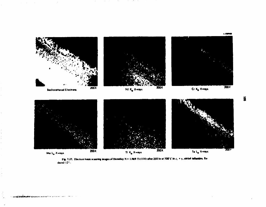
kt ftockicoM«»»d Eltcrrorw wox Nl K, X*«yt JOOX Cr K, X f «yi MOX
KAo L 0 X-foy» 200X Tl K 0 X-roy» aoox T« L a X-rayi
Kij.?.J7. lkMionh*»m*«iM»*iim*f»<»fMf»lelloyN + l.<M* T U I M U f t t f M O h u l 7«rCIn,) , • >. ftkM MhtrMti. !»•• Uucvd 12':.
§
• ^tvmmUhCHHMWl^AH-JHIvgt- « l i u f

109
slightly higher than in the base metal. The tellurium was detected throughout the reaction layer and appeared to concentrate in areas that were low in molybdenum. Atomic-absorption analysis showed the concentration of tellurium in the reaction layers to be 33.6 wt %.
The scans for 583 alloy, containing 1.79% Ti. are given in Fig. 736 . A thicker reaction layer (actually two layers together) was observed for mis aBoy (rote the magnification of only 200 times). The interface between the metal and reaction layers was nearly a straight line. Nickel was observed in high concentration in the layer nearest the base metal, but only snail amounts were found in the thinner outer layer. The reverse situation was detected for chromium. Again, molybdenum appeared slightly concentrated in the first layer. However, no molybdenum was present in the outer layer. Titanium was distributed uniformly throughout both layers. The tellurium was found in both layers but appeared to be concentrated in the outer layer. The average tellurium content for the combined layers was 34.9%. In other areas of the same sample, chromium was not always detected in the outer layer. The explanation for this is unclear at this time.
The results for the 2% Ti modified alloy 114 are shown in Fig. 7.37. As in the case for S83. a relatively thick reaction layer had a uniform interface. However, a distinct outer layer was not present. Nickel appeared to be present in the reaction layer in moderate quantity, and the amount of chromium was less than 5%. Again, the reaction layer appeared to be slightly enriched in molybdenum. Titanium was observed in about the same concentration as in the base metzi. Tellurium was detected throughout the reaction layer but was slightly depleted in a iayer near the interface. The tellurium content of the reaction layer was 37.5 wt % as determined by atomic absorption.
The results above differ somewhat from earlier investigations by Gehlbach and Henson where Hastelloy N foils were exposed to tellurium vapor at different temperatures.14 We did not find any striated nickel-chromium tellurides of the type that were observed in their Knudsen cell exposures at 750°C. However, both their earlier work and ours found material near the outer surface that was enriched in molybdenum. Additional quantitative analyses of reaction products are in progress to broaden our understanding of tellurium attack. The results should be useful in characterizing the Hastelloy N tellurium reactions in ways that will be helpful in interpreting the alloy screening tests.
14. R. F.. Gchlbach and Helen Hcnwn. MSR Prcgram Semiannu Fro*. Rep. Aug. 31. 19V. ORNL-4R32. pp. 79 97.
7.12 J X-Kay Mfesctnm A—r>»
X-ray diffraction has been used to analyze the reaction products scraped off 5065 and 114 iprcimem In both cases. NijTe : appeared to be the nam reaction product. This result is similar to that reported by Gehlbach and Heason.' * SiTe. * , may also have been produced, but differentiation between the two compounds is difficult since the interptaaar spaemgs of both are nearly identical. Other extra lines can be isdexed to several lines for molybdenum telarides (MoTcj. Mo }Te«) and/or chromium tefurides (Cr 3 Te ] . CrTe). but the identification of these ones most be ronmVrrd tentative. The extra lines may actaaay be due to the formation of ternary compounds such as KKTr-Te. Positive identification of such com pounds is difficult because their interpianar spaemgs have not yet been indexed and do not appear m the ASTM file system.
1. Hastelloy N alloys were severely corroded by direct contact to & and y, nickel telurides at 700°C for 250 hr.
2. The titanium-modified alloys. 583 and 114. exhibited only shallow intergraniuar cracks after tensile testing but were subject to moderate general tellurium corrosion. The reverse situation was observed for standard Hastelloy N (5065).
3 . Electron microprobe scans showed the presence of Ni. Cr. Mo. and Te in the reaction layers, titanium was also present in the corrosion products on 583 and 114.
4 . The concentrations (by weight) of tellurium in the reaction layers, as determined by atomic absorption, were 33.6. 39.9. and 37.5'? for 5065. 583. and 114 alloys respectively.
5. The main reaction product appeared to be NijTc 2
or NiTe0 6 , as shown by x-ray diffraction analysis. Numerous other x-ray lines were not positively indexed and may be associated with other binary and/or ternary tellurides.
7.13 EXAMINATION OF HASTELLOY N SPECIMENS EXPOSED TO TELLURIUM
H E McCoy J. Brynesiad D.Kelmers B.McNabb
The status of screening tests for evaluating the influence of tellurium on Hastelloy N was previously discussed." Since that time, screening tests for expos-
15. M. E. McCoy. MSR Program Semmimu. Progr. Rep Aug. 31. 1974. ORNI.-50II.P 79

Tabto 7.17. Summary of obwrvalioM of HiMvNuy N T« mvtfciM IN wvml HfMntag Mtt
1 \pmuic sxndiimn^' H I M I numbe!** Wvifhl vhunye
A\ Annvrflvtl 40*0*3 4 7 | * M 471114
2*0 hi 416*0 < in telluiulc miMuiv H
40*0*.* 4 7 H I 4 474*1 ) 4 74*14
I.IIW
Low Low
•MM hi 4l 7 I M H m lelluriik mix Hire \
411*06* 471)14 47I5HJ
o.oo22 O.00I4 0.0016
l lMNll ir ,|l 7INI ( HI icIluriUv miMiiii' A
4o*06* 4 ; n i 4 471**3 471**4
o.o2 iv o.o2vv 00214 o.oiv*
2*0 hi .il 700 ( in lelluiivU- miMuiv H
40*01)* 471114 47 I S M
I.UW
l.tlW
2*o hi J I 7 IH I C m IOIIUIKIV miMuie (
4o)06* 471114 4 7 I J M
1 i m l o w 1 OW
I INMI I i ; ,,l 70O < I I I l e »4"ul i l l ' 4l *0O < •
4 o*o(i* 471114 4 7 I * M
0 04107 ouim
4im hi 41 7mY< in K' V.l|>l.l 1 I*' 41 4*0 'C)
40*06* 4o*i 16*
1 OW Low
Mutiillugiuphk "bwivjliom SHCM 110' |H|> hlimmitun (%t RetlutOon
YwM« Ulnmniv WlHltt UnMuim l i . l l l
In tit* 1*1
4 7 7 IJN4 41 2 44.7 J26 4 * 1 12 IV 6H..I 7 * 1 60 2 4S.M 1224 66 * 71 H 4N.9
46 1 1124 mv 41 * 4 7 6 . * • » . * V2 1 4H6 40.6 4VJ 41 2 V62 4 2 * 44 1 SH.6 4HH l < * 1 .17.* I V * * « 4
47.V 121 H 45 1 4110 4 7 7 4'l J 117 7 4 V 1 ii* 4V 1 * l X 127 4 4 6 * 4DV 46.1
VI .6 1 \i H "i a 4 2 ) 4 ) 2 61 * U N . " 4< 5 1 l l K M l * 2 V 124 1 4V2 S2V * ) * * 7 . * D u n 42V 46 7 *4 4
»74 •M4 *7< 17 V 44 I IHO 'Ml 1 I I . l 4H7 6 0 *
4 0 2 VM.2 4 2 ' 44 V 60 0
14 4 M l . 4l. 1 4K 1 66 4 I I I 7 V I * I 6 ',4 1 611.) M i l HI 6 44 ) 46 7 6 0 7
4 * 4 I ' l l * »4 1 .14 V U t 4V 1 iov.2 Ml * * 0 41 V * l 7 1 IV 6 4 2 6 4< I I 41 1.
50') 122 1 4.1V 46 ft »V1 * l 1 122* 4 ) 4 4* 7 - ! 1
Hejiiion l4>vi. i i jrk" «.! * mils H041l1.u1 Utyci, l«v\ clacks •. I mtl Hi'mlhin Uyci, vuik<. v l mil Nv4tiH<n Uyvi, W4tk» • I mil
Noii. ickt lew ..Mikv ' . on2 mil I ow w.nkv «-:<i.nj mil
Si'iue ivil.iU'tl Miil.no IU.KOKII, Ivw if.nks Some i\nl4lvtl Miil.no itMclioii. lew ..u.ks Si'inv iviUivU MIII.KV KMiUtm. lew ..Miks Some isolated suilote icuiiiiii, lew . uck»
Ke4il|.i|l 1,1)111, i l .uks * Hills Jv'v'|i HcKihrn l.>)ci lev. >i.nk> < I mil Hi'.u id in l.tjoi. low ci.it kt >.. I mil
Ki'.u ii<m lu>vi. ci.icks' I mil He.li Hull I.I > 01. Mo tl . lt 'ks MtMiii.m Liyt'i. no ii.nkv
( i,itk\ >.* mil SII.III.A KMI imn l.i>cr. w,uk> «'.* MIIK Slullow 1c.11 thm l.i>oi, >i4tks <* milt
Ci4ik\ >% I mil
"IvIluiKiv'iniMuioswvivoompuimJt'U .IN IOIIOWN A nitkol • .i, nivkvl IVIIUIHIO, H • ,1, ' >, nukol lolluniiox. 4111K - >, • * PKkol IOIIUIHI *Sw l4ble> •" 2 ,mJ 7 7 1 ln.muim M.mviHi.nioiiMi..inin4lK 2 ioi ho.ils 47 UK I. 471 114.4 74* H, 4ml474**4 4inl ir 1.11 (u'jl 40*06* 1 1 r«'»i» run .11 2* 'C 41 4 >H4in 1410 ••!' 0.0* mm '

I l l
Me. icasne tpctimews t»» teanrmm are beau; consakaed M am T45BR the lW\ of teanrwKn wal he about I U " afcvas cm" : sec"'. *o the tcreemag tests weed to Mtofve fluxes ui saatar muju i fdn Ihe Methods MVCMKHCd thus LM U K i h t drStuCUttoa ptesuwe ot Mckd leaundes or die vapor ptejuwre ««t M t m M Metal a* sources of tetwrvua Teusar W O M B were exposed, J M ! their were swbseqacarii artonacd to fawaue. The fractured vaupks were exaaaned a a u l o -eiMhtidli !•• At n i l l the extent •< uHeignnular crackmg. The results of the tea* duae to date are — M j n « d M Table ?. I T
Sauwdes of four heats mete exposed to ufwrwte unture B I Tahk ~ I7» for 250 hi at b50 a C. The sanqdes were CMbedded m scut1 particles of die • n i w M a quart/ lube, evacuated, ant tested. The ru»«onacrigiaphj t t w n M Fag. 7 J S show that the •ipnwnmi fonwd duck reactaou layers aMl shalow miiUjimala tracks to a depth of I to I -5 nats. The inunlri. lost weight M T I M the expiate because of *fu~hng of the reaction product. The tosses M crost-seciaonal area are Ktety responsible for the decreases M ihe >»rld awl tevrje stresses.
Sutmytr i. w . e exposed to nickel leuunde mature A. which lead a lower dissociation pressure of tclmuj-n than matures B and C. The first group was exposed for 250 hr at 700*C. and the weight gains were abowt 2 mg. which corresponds to a flux of abowt 2 X 1 0 " aloMS C M * 1 sec' 1 . No reaction layers formed, aad only shaaow cracks ^D J Md fanned in die two titjuwnu modified aloys (Fig. 7J"»). The samples exposed for 1000 br gamed abowt 20 mg. wwh an effective tcuuriam ran of about 5 X 1 0 " atoms cm" 1 sec' 1 . However, these specimens Ad have isolated regions where surface reactions occurred. That, the weight gam mdwdes particles which effectively smlered to the specimens, and die flux of reactive Iduriwm is lower than die above value. These specimens had a lew shallow crack'. (Fig. 7.40). Some smal changes occurred m the mechanical properties, bat these laxly resulted from carbide precipitation daring me 250- and lOOO-hr anneabat700*C.
Samples exposed lo mixture B for 250 hr at 7O0*C underwent extensive chemical reaction. A deiaded post-test examination of these specimens was made by Braski.1* Thick reaction films were produced, and large weight losses occurred due lo their spallmg. An interesting difference was that the titanium-modified alloys had thicker reaction layers, but (he cracks formed during lensne testing were shallower J Fig. 7.41). The reduc-
I*. Sec Sex i n * 7 12. ihn report
twas M vuid aad tensde stresses were fakery due to redaction M the ciust-secinmal area b> the extensive reacwua layers
The i untili i exposed to nnxiwre C unarrwcr.f even further chenacal reaction. There was very hi tie len-dracy for mtcrgr malar crack foranoon (Fm. "-42K The leawctsons M the arengrh roraavters were hfcd> due m reductions M the c oss sections by ibeuucat reaction. However, the total elongation and reduction m area wcte not reduced naure dun coaU be accounted lor by carmde precaMatwa.
Oar set of saandes was exposed m a <jaaru i-apjuV it 700'C wwh lewanam at 3 0 0 T The partial pressure of teaarmai under these conditions a abowt I X | 0 ~ ' ton The three samples were m the same capsule, and the wesjht gains shown M Table 7.|7 are mdscatjve of the extent of the bum LamhcJ reaction- Ihe standard Itastedov N specimen g. nee" oar* about 0.1 mg. whereas the inaumm-modw ed '-:oys gamrd about I Mg each. The standard ran—ru dnt not b a n a ctsdde reaction layer, bat die two muualtd specanens did have reaction layers. The average lehunau flux reacting with the standard specimen was about 10** atoms c m ' * sec ' ' . whereas that reacting with the titanium m jdtned aaoys was 1 0 " atoms c m " 1 sec' ' . The extent of crackmg m a l three specnaens was abowt equivalent, and the muunum crack depth was about 5 nuts iFig. 7.431 The changes in mechaniral properties were tsync smal aad can be accomned for by ihangei due to
The last two specimens (Table 7.17) were exposed to ienanum npor in an experanrnt designed to luat the rate of transport lo the saecintens. examination after the first 100 hr showed that the reaction proceeded more rapidly at the end of the specimen closest to the ie~fanmav The sampfci were turned twine and exposed at 700'C for a total of 400 br. The weight rtiaagtj were negative, and nickel telundes were farmed ebewhere m the system. No reaction layer was niebBographicaUy nstbie on the specimen, but the deformed sample formed cracks (o a depth of about 3 mns(Fig. 7.44).
The tests described m this section represent a variety of test conditions and specimen compositions. Tiny are not adequate for firm condusions. but they mdtcaie some important trends:
I. The tests reaffirmed the extreme sensitivity of standard Htstefloy N to mlergranidar embntilement when exposed lo telunum fluxes of urdy about 10 ' * atoms c m ' 1 sec' 1 . However, the unknown partial pressure of tellurium in eowdibrium with idlunde mixture A was not sufficient to cause significant cracking.

- > ; .>
-x--
- • X - V : ^- - - ?
• - - = — - < < _ • • = - .
» "-
- -?» - . ^
I <«)
F^. T.J*. nBtHMCMpapfa «* ' F # f pfcrfo^rj"** not frjrfare. Krrfcei tf'i Trp*ral c^(* -cjrlmft mi •NMmaH pjfl. A Hnt474SV. *m«.

~~--*5S
r ••"•SSte.
BLANK PAGE

112
&
0 0 3 3 in
( f )
7i%mm
,0.010 in^ 0 25mm
by M jftcimt*%€XpiMt tn lUNiM* W B l t B tnr 25W Iw »t M P T tt>4 %tnim4tH JS'C. ftma r t t o V * f j l H o i 4050*5. I M I k i i 471-114 <. I H o i 4745 VV (di Hot 474$ *4. %< pnlnhril <r» l l d l 4050h5. |00x. If) H t . i 4O5065. 5no< i ( ) Hc<l 4745 M lOOx rh>
2 (h)

•zar3a#iscius>3Te^?^-.£&&G^
BLANK PAGE

•
112
( f ) 4)002 in., 0.051mm
(h) [J)002in.. | 1 0.051 mm '
3

113
2. The bulk chemical reactivity of the titanium-modified Hasteiloy N with tellurium vapor seems greater than that of standard fbsteiloy N. Since the total quantity of tellurium produced in an MSBR wiil be small, the greater bulk chemical reactivity of the modified Hasteiloy N may reduce the amount of tellurium reaching the gram boundaries.
3. The titanium-modified Hasteiloy N is not immune to intergranular cracking. The present tests do not
provide the data required for quantitative conclusions about the relative cracking tendcscies of standard and titanium-modified Hasteiloy N.
The nickel teUuride mixtures designated A. B. and C provide partial pressures of tellurium which are too low. too high, and too high respectively. Tests of other teUuride mixtures aie in progress.
(a) » «
V 127725
(b)
12772*
( C )
100 I
0.005
200 t o3
MICRONS — 100X— r
600 •
700 I
*0 INCHES 0.020 0.025
F«. 7.19. flwunwkioyplw of H l d b y N ipMwam expo—t to ffctw» mktmt A far ISO hr at 70TC i f.dpc of strained specimen near fracture. As paSslicd. lOOx. d ) Heat 5065. (b> Heat47l-5S3. (c) Heat 47I-M4.
„t2S'C.

114
y-ta»7i»
(a)
(b)
V 11*726 W*J
(c) V-1M72*
' ^.:'-..'v-'I--j.:.-"''*l 0.84mm •
(e) I p 002 in v I I n fWM mm I
F » 7.4a mmutkiugiaplu of HatoSoy N W K W W I expoead to liOurMi Mixta** A for 1000 kr at 700*C and itiainad at 2S°C. Edees of Muined ^crimen near fracture. *« oolished. 33x. (a) Heat 405065 (standard Hastriloy N). (b) Heat 471-1(4, (c) Heat 474533. (d i Heat 474534. (e) edte of unstressed portion of ample (Hot 474-533) showing typical reaction product. As polished. 500x.

115
13773*
( f ) 1O0 200
L— l _ MICRONS
-J IOOX— 600 700
0.005 0010 INCHES 0.020 0.025
Ffc. 7.41. r*otomknpq»» of HarteMoy N specimens exposed to tdtaride mixture • for 250 rtr at 700*0 and ariinad «t 25°C. Edges of strained specimens near fracture. As polished. lOOx. (a) Heal 405065. <b) Heal 471-114. (c> Heal 471-583. Edges of unstressed portion*showing reaction layers. As polished. lOOx. (d) Heal 405065 (e) Heal 471-114. and (0 Heat 471-583. Reduced 12%.

116
(e)
r - - , * ^ ? " j*&&r-*~*
(f) 0010 in. 0.25mm
F t 1M. HMkHMfcopaatoof ftMMby N sBccJmc** exposed to lc>wide mnnve C for 250 hr ai 700* C and sttaiwd at 25°C. Edge of strained specimens near fracture. As polished. lOOx. (a) Heal 40S065, <b> Heal 471-114, (c) Heal 471-583. Typical reaction layers on unstressed portions, (d) Heat 405065. (e) Heat 471-114. and (0 Hsat 471-5*3. Reduced 20%.

11?
-' . * • « .1U
'M
- - » - « •
5
I L
( d )
Ffe. 7.43. PkotomicrofnplM of I at 25°C. Section near tract
Umimted shoulder \\ polished. 50(
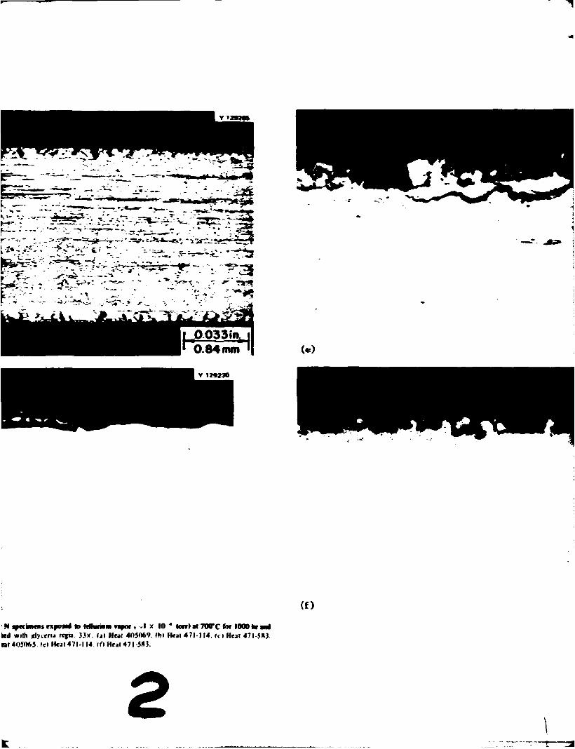
(e)
( f )
' N fpeeimens expoai to fdhwiom rwjai, - I x 10 * tort) at 700*C for 1000fcr Md ltd with rfyiena regia. 33x. (aI Heal 4O5069. (b) Heal 471-114. Ii > Heal 471-583. ral 405065 le) Heal 471-114. If) Heat 471-583.
2

BLANK PAGE
'•^"- • • * ' • ' ,,<•> ' - V c . - . ' ^ - W U m » l f » , „-J v-^V-.1, . . IF

«-J . . .
30331^ ).84mm
Y 12*230
(«)
• 7 « r c for 1000 k*a«i -114. <<>H«t 471-5*1.
I
(f) |p.002in. | 1 0.051 mm '
3

r iVjswf. &.>i*;,!«» i ' ^ * * ^ * s^ , .
!i
BLANK PAGE
j i j • -h..^u\>M HJ.'*"* }' • •""..'-• '

l i t
^ > ,
' * »
, 0033 ia , ' 0 . 8 4 mm il
(b) Igrain., I 1 0051mm >
f%. 7.44. rhotomkmgnfltt of HasicHoy N ipetimtm rxpoicd lo itNwriwn vapor (TmnpirMion txperimtM) tot 400 fcr at 700"X ami Sinmed af 25 C. Hc-it 4<>5»>65. u» .Section near fra-Mure. etthed with glycctia regia. 33X. <l»» I'ntfreMed shoulder. » polished. 5IHX.

119
7.14 OPERATION AND ANALYSIS OF TcCo-1
C. R. hyman
TeGen-l was the fast m a series of ORR poofcaie ixradutioa experiments designed to nradaie prospective MSBR vessel materials undrr conditioni expected m a molten-salt breeder reactor. The expr-i—int was designed to produce a fusion product inventory similar to that found m the MSRE when mtergranular cracking was lira observed. Probably the fission product idlu-m m is the chief came of this cracking. Therefore, this experiment was designed specificity to produce a tellurium inventory ot at least 5 X 10* * Te atoms, cm 2
at the metai-to-alt interface toftther with a representative nix of other fusion products.
The test device was an irradiation capsule conumiaf three 'A-in.-OD. 0 035-w. wall. 44n.-long tubular fuel pins, partially filed with fuel salt. The three fuel pins were type 304 stainless steel, standard Hasteiloy N. and Inconel 601. The fuel pins were filled with "U cm 1 of fuel-salt, ieaving a '/t-in. void at the lop of the pea. which was filled with helium- The fuel salt was a mixture of L i F - B e F : - Z r F 4 - : J , L F 4 - J " U F * (63.5-29-5-1.0-1.5 mole l l
The fuel pins were arranged vertically inside a double-walled type 304 stainless steel vessel. The void between the fuel pins and the inner wall of the vessel was filled with NaK for improving heat transfer. A schematic drawing of TeGen-l is shown in Fig. 7.45. The capsule was instrumented with four Chromel-Alumel thermocouples per fuel pin. One electrical resistance heater was wrapped around each fuel pin. and these healers were positioned to minimi/e axial temperature gradients while the experimeni was operating. The heaters also kept the fuel pins about I50°C during periods when the reactor was down and while the capsule was removed from the reactor after completion of the irradiation but prior to hot cell disassembly. Fission product decay radiation in cold K I 5 0 ° Q irradiated fuel causes dissociation of the fuel salt components and consequently leads to the release of fluorine. Calculations indicate that fluorine pressures as high as 440 psia could be generated inside the fuel pins if they were allowed to remain for long periods at ambient temperature.
The design operating temperature for the specimens was 700°C at the salt-to-mctal interface and was maintained as uniform as possible over the length of the specimens throughout the duration of the irradiation. Bulk temperature control was maintained by adjusting the experiment position with respect to the reactor by
Means of rhe movable track on which the experiment was placed m the ORR poolside facility. This movement changer the neutron flux at the expertm mt and thus varies the fission beat produced. Fine temperature adjustment and uniform axial temperatures were attained by heater power nsawpulaiwn. A more complete description of the experiment may be found m an earlier report.'7
7.14.1 Ttjinlmi Hustory of TcCen-l
TeGen-l was inserted ie'o the ORR pootside irradiation faculty position P-4A on September 19. 1974. It was irradiated for lAiA hr during ORR fuel cycles 121 and 122 with the react.* at the ful 30-MWt| operating power. The irradiation was terminated on November 25. 1974. at which t.me die capsule was retracted to 13 in. away from the reactor face. On December 3 . 1974. the capsule was removed from the poolsidc facility and hung on the south side of the ORR pool with all the instrumentation left intact. During this time, the specimen temperatures were maintained at an average of200*C.
The enly occurrence not expected during the irradiation was the change in flux that occurred upon the removal of a large experiment in the P-5 position adjacent to the P4-A position. Before removal of this adjacent experiment, the TeGen-l experiment was operating at 700°C. After removal of this other experiment, the TeGen-l capsule had to be inserted 2.3 in. further toward the reactor to compensate for the decrease in the local thermal-neutron flux.
On February 10. 1975. the capsule was transferred to the ORR hot cell, at which time it was disassembled. Personnel from the Metals and Ceramics Division then took charge of performing the chemical and metallurgical evaluation.
7 14.2 Data Analysis for TeGen-l
Table 7.18 gives typical operating data. The average thermocouple reading over the length of the experiment was 703°C. This corresponds to a calculated average temperature at the fuel-salt-to-fuel-pin interface of about 7I0°C. The maximum temperature variation occurred in the bottom fuel pin. This temperature difference of I03 8C can be explained by convection currents existing in the NaK at the bottom of the
17. ('. R. My nun. MSR Program Scmiennu. Progr. Rep. Aug. 31. /V7.T.ORNI.-50I i.pp. XI 85.
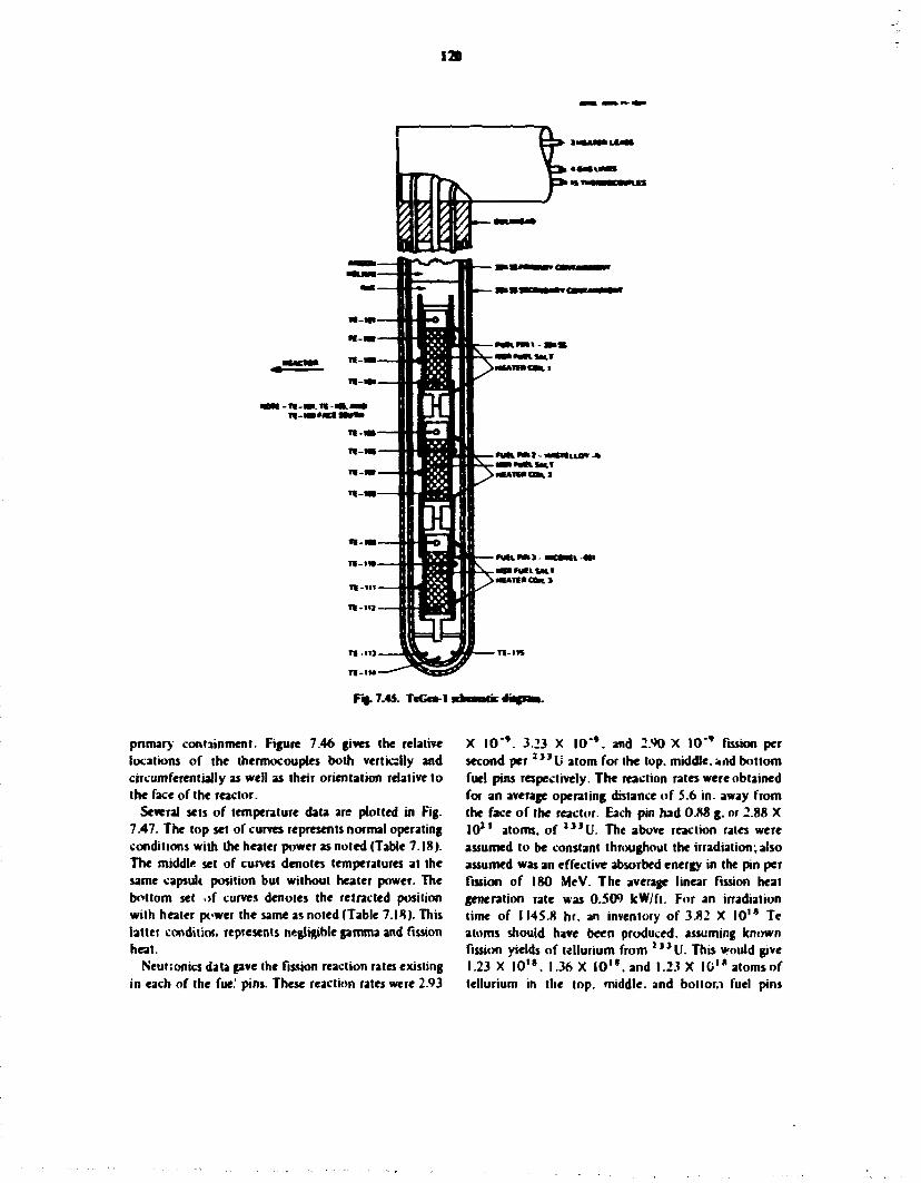
12D
F*. 7.45. T«Gen-l
pnmary containment. Figure 7.46 gives the relative locations of the thermocouples both verticslly and circumferentially as well as their orientation relative to the face of the reactor.
Several sets of temperature data are plotted in Fig. 7.47. The top set of curves represents normal operating conditions with the heater power as noted (Table 7.18). The middle set of curves denotes temperatures at the same capsule position but without heater power. The bottom set .>f curves denotes the retracted position with heater power the same as noted (Table 7.18). This latter conditio!, represents negligible gamma and fission heat.
Neuronics data gave the fission reaction rates existing in each of the fue.' pins. These reaction rates were 2.93
X 10"'. 3.23 X I0"V and 2<J0 X 10** fission per second p e r 2 " U atom for the top. middle. »nd bottom fuel pins respectively. The reaction rates were obtained for an average operating distance of 5.6 in. away from the face of the reactor. Each pin had 0M g. or 2.88 X I 0 1 1 atoms, of 1 , J U . The above reaction rates were assumed to be constant throughout the irradiation,also assumed was an effective absorbed energy in the pin per fission of 180 MeV. The average linear fission heat generation rale was 0.509 kW/ft. For an irradiation time of 1145.8 hr. an inventory of 3.82 X 10' • Te atoms should have been produced, assuming known fission yields of tellurium from 2 , , U . This would give 1.23 X I0*». 1.36 X 1 0 " . and 1.23 X IC'* atoms of tellurium in the top. middle, and bottom fuel pins

121
r 7 .1 * . Typical • rT«Gt* - l *
Spconcn l ioarr pwwtl
ThtuNiumpfci Trntpt i j t tc
Top J * 2 4 101 72 J 13<M iLunlru itcril 102 700
103 * * S l o t 712
JtMk * l « 595 7>* i H u l r i U M 10* 734
107 7 1 * IOS * » J
l o t t o * •5.: io» 710 I h c i M d U I I 110 707
I I I * U 112 434
*CapwJt pnatiun $.4 in. tctiactcd from rcstl<it face.
ONlfNTATlON
nt ACTON
U 103.107.111
T t 10». 10*. 117
T i 101. 105. I0»
T I 107.10f. 110
Tf I
101
109 103
I 0 f
IOC 107
10*
109 110 111
112
AXIAl LOCATION DISTANCE FNOMHM
400 325 •
I 75
0.50 0 9 0 • 1 25
-2 75 •
4 0 0 -5.00 575
-7 2 5 -
I rutinNs
31
X
30* SS
NfACTON HM»
HASTfLLOV-N
INCONtL M l
n.r
Fif. 7.4ft. Thermocouple ktcatinn and nrinilalinn infor ma!ir>ii.

122
Fit-7.47. F»dyimwftc«iMiipiiOn mmmMfosHiim.
respectively- If ail the tellurium were deposited on the specimen metal surface, the specific inventory of tellurium would be 4.7 X 10'*. 5.2 X 10'*. and 4.7 X 1 0 " Te atoms per square centimeter of metal area for the top. middle, and bottom fuel pins respectively. These calculations assume that all the tellurium was deposited below the salt level. These specific inver.;o.ies are acceptably close to the 5 X 10'* Te atoms/cm2
required by design criteria. Figure 7.48 presents the design temperature profile as
a function of radial distance from the center of t^e fuel pin. This profile was based on a one-dimensional analysis using GENGTC.1 * This analysis did not take into account the end heat losses, nor did it account for the convection currents that may occur in the hot fut • sa>t. Also, the input data to this program assumed that the fission and heater heat were averaged over an effective length of 14 in. Figure 7.49 gives the relative radial temperature-profile estimates for (he (op. middle, and bottom fuel pins tespectively. Although exact temperature distributions are not known, the differences in the respective fission reaction rates in the fuel pins cause the centerline temperatures of the middle and bottom fuel pins to be higher than for (he top fuel pin. As a result, the temperature gradients in the fuel
IH ». C R..l.in<l. OhSCTC A OneDimensional CEIK Computer Program for Capsule Temperature Calculations in Cylindrical (kon.etrx. ORNl.-TM 1942
pins differ substantially, radially as well as axially, and therefore may effect the corresponding fission product deposition rates on the surfaces of the fuel specimens. This occurs in spite of having the same temperature along the outside of the fuel pins. Note that the temperatures at the surfaces of the fuel pins are the respective averages of the lower three thermocouple readings on each fuel pin in Table 7.18. These thermocouple readings represent actual fuel region temperatures and not those of the void region above the salt. Also note that the heater powers (Table 7.18) provide heat to the ends of the fuel pins where little or no fission heat is produced. This has the effect of leveling out the temperatures over the length of the experiment (Table 7.18).
During the data analysis, a comparison was made of the fission heats produced as calculated from neutronics support and those indicated by a thermal heat Salance. The thermal heat balance technique required certain assumptions. First was the assumption that absolute heater power inputs were known. However, the original design did not specify precise measurement of heater power, and. as a result, the instrumentation was not calibrated to provide high precision. Second, gamma heating rates were assumed to be the same as when the experiment was first designed. This was not precisely correct, because ihe reactor core configuration has been changed since that time, thus changing the gamma flux. Since the gamma heating rates as well as the electrical

123
saMMf o n s M n i u s f itcrmcM. HCAT OF I H M M I
r proAr fesga f r a * GENGTC calnbtiMS.
calibrated meters on line so that accurate electrical power rr.easuremnts can be made. Accurate gamma heating measurements as well as improved flux mappings of the poolside facility are planned, also. With these improvements, a more precise thermal calculation should be possible.
7 15 EXAMINATION OF TeGea-l
B.McNabb H E . McCoy
TeGcn-1 was designed to study the effect of tellurium and other fission products on containment materials of interest to the MSR Program.1* (TeOen is an acronym for tellurium generator.) The experiment was operated in the ORR poolside facility P4A for 1145 hr at 700°C with the ORR operating at 30 MWf t) during fuel cycles 121 and 122.
Three fuel pins (length. 4 in., diameter. % in.: wall thickness. 0.035 in.) were each filled with 7.14 cm 1 (3 in. depth) of MSR fuel salt containing 0.78 g 1 3 , U . A total of approximately 3400 Ci of mixed fission product activity was estimated to be generated in each
19. R. L. Senn, J H. Shaffer. H. E. McCoy, and P. N. Haubenrckh. MSA Prognm Stmmmu. Trop. Rep. Aug. 31, 1972, ORNL4832.pp.90 94.
Fig. 7.4B. TeGca-l at In walk ndiri H f i n l w t
heating rates were a large fraction of the total heating rate, any calculation of the fission heat by heat balance would be subject to inherent errors. Fina'ly. the thermal model used in the heat balance did not take into account the heat losses that occur in the ends of 'he fuel pins.
As a result of the above uncertainties and the uncertainties involved with neuironies methods, the disagreement of the two calculations amounted to a maximum of 2 0 " in the fission heat production rates. Additional information on fission product production will be ob' rned when complete chemical and metallurgical analyses arc performed.
7.14 J Future Irradiations
Future TeGen capsules will be basically the same as TeGen-l. but with different fuel pin materials. In addition, eight % X % X 0.005 in. foils will be suspended inside each fuel pin. Four will be placed in the space above the fuel salt, while four foils will be suspended in the fuel salt at the bottom of each fuel pin. These foils will be made of the same material as the respective fuel pins.
In addition the heater coils will be distributed to give a more uniform axi.,1 temperature profile, and heater power instrumentation will be improved by installing

124
FOSHMMOr • K n i t
Fig. 7.49. ReMre raddi U i f t r i f r t profdcj for fbr top. Middle, and boftorn fad pi W>. thermal n>ndi*ir»iy of fuel»3*0.6«»l<. Biu hr-fi-F ntf»l-<» W cm- ('».
. Fmiim ho i noted: jumma heal «as 05
pin. and the tellurium concentration was estimated to be about 5 X I0 1 * Te atoms per square centimeter of contact area. The operating conditions and design characteristics were reported previously.17 The fuel pins were made of (I) type 304 stainless steel. (2) standard rlastelloy N. and (3) Inconel 601 and were doubly contained in a type 304 stainless steel sheath. The fuel pins were in contact with NaK on the outside surface and with fuel salt on the inside. There was a %-in -high helium-filled gas plenum above the fuel salt.
TeGen-l was removed from the reactor flux on November 25. I**74. r.y retracting the experiment 13 in. from the reactor face. On Drcember3.1974. it was removed from the poolside facili'y and hung on the south side of the pool with the fuel pins kept at 150°("
to prevent fluorine evolution from the fuel salt. On February 10. I">75. the power was cut off the heaters, and the fuel pins were moved to the ORR hot cells for disassembly.
The fuel pins were examined visually and photographs were taken during disassembly. Figure 7.50 is a composite photograph of the three fuel pins when first removed from the NaKfilled assembly. A 50*£ mixture of alcohol and mineral oil was used to remove the NaK residue. Some unreacled residue cari be seen on the thermocouple wires at the top left in the photograph. The Inconel 60i fuel pin was at the bottom (right), (bstelloy N in the middle, and type 304 stainless steel at the top (left). All the fuel pins, heater coils, thermocouples, and flux monitors appeared to be in

H-66467
Ffc 7JO. CompoaMa photograph of TtCan-l fuai eapaitoi u rtmovatf from aaaambfy with hour colli, tnarmocoupla* ami flux monitor intact. Incoiwl 601 futl pin ai boiiom rijhl. HaMalloy N in middle, ami 304 ifainlai* ileal ai (up toft.

126
excellent condition. It was determined from flux monitors and thermocouple readings that the surface shown in the photograph was facing the reactor during operation. The longer section of 'A • -in. heater coils was at the top and the shorter col at the bottom JI each fuel pin. The thermocouples are the same size (V,» m.l as the heater coils, and the flux monitors are smaller wires. The shaded areas in the photograph arise from a difference in lighting for the several photographs required for the composite. The titanium flux monitors were embrittled and could not be removed intact, but the other monitors were in excellent condition. The fuel pins were separated from the assembly, identified, and placed in a furnace at ISO'C to prevent fluorine evolution. They were maintained at this temperature except during transfer between hot cells and during gamma scanning and sectioning in the hot ceils.
The fuel pins were gamma-scanned in the High -Radiation Level Examination Laboratory (HRLEL)
facility using a sodium iodide detector in conjunction with a |7-in.-thick lead collimator with a l-X-O.OI-in. slit. A counting time of 1 min and an excitation potential of 10 keV/channel were used for the irradiated-sait-bearing portions of fuel pins, and a I0-min counting time was used for the gas plenum and an unirradiated control pin (Hastelloy N pin 2AI and for background. Figure 7 J I shows the gamma scans of the three fuel pins (length in inches vs counts per minute, with 100.000 being fuli scale) scanning from the bottom to the top. Note that the top pin (type 304 stainless steel) and the middle pin (Hastetloy N) haw a spike or sudden increase in activity at the top of the fuel, but the bottom pin (Inconcl bOI) has lower activity and does not have the spike. No explanation can be given presently for these differences.
Figure 7.52 is a plot of energy vs counts per minute per channel for each of the three fuel pins at the helium-filled plenum approximately % in. above the
-0»* Ti-rzot
••aSTEi.i.0* » *"•
NCONCi 40' •««
•om or w»
ro» Of S * . '
r vC* f< * . SOW
'wis. S U U . •00.000 cwn/VM STMOMO SCvMrion 0 * % £MC*«r MHCC C0UMTC0 O » T 0 o r 3 » r v
— •OTTOM or «%
» 40 SO 10 %sc*u
Fig. 741. of AMI paw from fltt TeGen-l expariMM. Scam made vertically from touo« to top of each pin.

127
salt level. The activated constituent dements of the fuel pins appear to be in qualitative agreement with their initial chemical analysis. For example. 5 , C r is higher in Inconel 601 . intermediate in type 304 stainless steel, and lowest in Hastefloy N. Additionally. **Co is higher in Hastdloy N. intermediate in type 304 stainless steel, and lowest in Inconel 601. These can occur by (iup) or (*.?) reactions wi'Ji die chromium, nickel, iron, and cobalt in the alloys. The chemical analyses of the fuel pins are given in Table 7.19.
Figure 7.53 shows gamma-scan plots of energy vs counts per minute per channel for the three fuel pins at or near the top of the fuel. For the type 304 stainless steel and the HastcUoy N pins, the scan was on the activity spike noted in Fig. 7 3 1 . Inconel 601 did not have an activity spike at die top of the fuel, and a scan was taken approximately % m. from the top of the fuel. The major difference in the scans appeared to be in the peak at approximately 0.485 MeV contributed to by , , , R u . , 4 * L a . * *Kr . and " C o and in the peak at
0**L-D«6 n-T20* 10
*'o S'Cr it, Cr
5 *Co.' 5 Zr,* 5 l»
BaCKGKOuNO (CuRve A) mconCL CCi (Cuftvt 8) MASTELLOY H (CURVE CI TYPE SO* STAMLESS STEEL (CURVED)
o-e i.o ENERGY (MfV)
Fg. 7.52. FICOTCHCII xawof tbcT<Gcn-l capMln wMn mc dt tutor 'A i

121
T a U r ? . i 9 . C h o B « i « i ] r x * « f T«C«a-l i
Ah>)r H o i » < « h I pnvcM Ah>)r H o i
Ni Cr Ke Mu Ma C St Al Ti
Tyyc 304 Mjwlnr I 7 W I X » 2 IS . * \ 7«».U O H O.0* 0.52 fled
H a t c l o y X NIS0»7 "-72.0 7.0 < : U.2 0.47 no* 0.4.2 OJE lac—ri *0 t NX35I0M 41 3 - i . ^ ti .w 0.1 J 0.03 9.2* 1.32 0.3!
.•oa& n-rtor
S * C * G « O U N O iCu**C »i MCONELCO* (CUftVES) * * S T E L L O T fc(OWVEC) Tr*E J O * 5TAMLESS STEEL iCt*vC 01
M > * « s l l -ps mttrfac*.

129
0.78 MeV contributed to by **Zr and **Nb. Scans were taken at the middle and bottom of the fuel, but the scans were similar to the ones just discussed except that the peak intensities were slightly lower.
The aaraeters of the fuel pins were measured in the hot cells with a micrometer (Table 7.20). The pre-test diameters were only known to satisfy the design range of 0500 to 0.501 in. The tubes were generally smaller at the gas plenum and largest near the middle. The maximum diametral change of 0.9% occurred in the Inconel 601 pin. These change: most likely occurred from several cycles of alternately melting and freezing the salt.
The pins were sectioned in HRLEL according to the schematic in Fig. 7 3 4 . The Vi*-in. rings (designated A) were for mechanical property tests. Auger, and metallo-graphic examination, the 'A-in. rings (designated B) were for leach and salt analysis, and the remaining sections (designated C) were retained as backup speci
mens. The rings were cut by flexible abrasive cutoff wheel (dry) with the pins heW in a routing chuck so that cuts were made just through the tube wal and not through the salt. The abrasive cutoff wheel was approximately 0.030 in. duck, but cuts nearly 0.06 in. wide were made due to the slight flexing of the Made during cutting.
Visual examuution of the meniscus of the fuel salt revealed differences in the appearance of the three pins. Figure 7.SS shows macrophotographs (approx 6X) of the meniscus after removal of the top cap and one 'A*-in. ring for pin A. the top cap and four %,-n-and one %ia. ring for pin B. and the top cap and two '/i*-in. and one 'A-in. ring for pin C. The meniscus of the type 30* stainless steel pin appeared to be level, with dendritic structure and shrinkage voids formed on solidification of the salt. It was difficult to obtain proper lighting on the meniscus at that depth from the lights on the stereomicroscope. The menscus on the
TaMe7
la indies
fed pint
Alloy Gas pieman Top of salt of salt
Bottom of salt
Type 304 stainless HastcBoyN IncondoOl ill
0.5035 0.5010 0.5045
03035 0.5019 0-5045 ill
TYPE OESCftlPTKM MO USC * 'At i". mm Fox MCCNMKAL
PROPERTIES S %m. FOR LE4CM (2 STEP) C SECTION TO SC RETAMEO
>T»-»OM
— EROCAP — » - l — • — A-2 — ' - 3 WD SALT LEVEL " _ A-4 - A-S — •
r — »-« • - A-T
— C
4 M. — »-• A-?
— A-10 — c
A- l l A- t f
— c »-!4 A-t» • A-Hi
— END CAP
F ( . 7.54. Schematic of TcCea fact pm sfcowmj sections to be cat.

130
F«- 735. Hwnugi^fci of 0n> — B W I W oT Ifec fart a l l « • * Ac topoT * c fed pm Mf>. «M HattcHoy > r«tl pin. middle. Kt laciHtriMM f»d pm. hn'fom. RrwWil 2?*.
h". iJ I VM tumlrvi \tcti fad pm.
131
ItasK-thn N pen I Fig. 7.5 5r> I had a different appearance. airJ (he sail appeared to have solidified at an angle (with tSe high side toward die reactor lace or possibly 1X0* away) The marking identifying the side l-cmg the reactor was wiped off accidentally and remarket' by ils rctaiionship w*th the top and bottom pins, so there could haw been a 1X0* rotation of the mark Ai he£er mafwfkaiii-4i there was some dendritic appearance, and some holes mere risible in the salt surface. The meniscus of the sail in the Inconei 601 pin also appraed *o have sondified at an angle, with the high side of the salt toward the reactor face. Ifcdes were visible at the salt surface and where die abrasive saw went through the top of the meniscus. The salt surface had a dendritic appearance, and some shrinkage voids were present.
No explanation can be given at this time fur the differences in the appearance of the salt surfaces in die three furl pins. Chemical analysis of the salt near the top and bottom of the sail may provide additional mfonMion. As the experiment was retracted from the reactor flux, about 13 in. away from Ihe reactor face, the shghlly higher flux in the middle(Ibstetloy Stand bottom (Inconei 601 I PUIS probably kept them molten tor a longer tune than the lop Hype 304 stauue&> steel I pin. When fufly retracted the puts were ai a small angle from vertical, with the pivotal point b.ing 132 in. above the bottom pin. The pins were at a small angle 12 J*» when in operating position, vei'rcai when retracted £ in., and at a small angle (4.6 »in the other direction when retracted 13 in. from the reactor face.
Ten of the '/..-in. rings from each pin (Fig. 7.541 »cie tensile tested in an Instron tensde machine in the hot cells. The rings were slipped over a split-ring fixture and pulled in tension until failure occurred- Due to the difficulty of deburring the rings withou* damaging the important inside surfaces, most of the ring* *ere not deburred properly, and some slipped oul of the fixture upon loading. A damp held most of the rings in the fixture to prevent their slipping out. Friction of the damp on the pull rods prcbably contributed to the higher yield stress on some of the specimens, but the ultimate tensde strength probably was not affected as much because of the higher loads. No correction has been made for the damp friction. The clamp friction varied from 20 to TO lb for typical runs, and the ultimate loads were jpproximately 500 lb. The control specimens included for comparison were tested without the damp.
Tensile data for the irradiated fuel pins and unirradiated control specimens are given in Tables 7.21 7.2J. An arbitrarily assumed gage length of 0.5 in. was used in the calculation of the yield strength and the uniform and total elongations. The values in the tables are not absolute but are useful for comparisons within the series. The properties affected most were the reduction in area and the elongation, tfastelloy N was affected most, type 304 stainless steel was intermediate, and Inconei 601 was affected least, if ai all. These changes are due to the oHnbmed effects of the thermal neutrons and the shallow cracking caused by the fission products.
tIM.Tr Hamrmf
* • * Cr.»«fc-
«vr*nMjl jcea
l l n * m.'t
haul ( i n * p^i
Srirrai lo* put U>«pr ioai~> R c U v K i M a * • *
Cr.»«fc-«vr*nMjl
jcea l l n * m.'t
haul ( i n * p^i Y«*r*
UlMUfC rnrak
f'rjcture
U>«pr ioai~>
lV*MM*«rT
Cr.»«fc-«vr*nMjl
jcea l l n * m.'t
haul ( i n * p^i Y«*r*
UlMUfC rnrak
f'rjcture T . i J * l'Mf<wm* • '"T-l
i-* 5 24 TO? 7;M 112.3 111' * I7.40 I6.20 16.62 1-2 4.67 M.3 6 * .5 I«I77 I ' M ! 15.60 I3 .*0 27 99 1-3 v a n frit 3 63.6 i n i . j 99 2 1 9 * 0 1*64 20.44 1-4 5 * 2 5* 1 * " J I 101.3 74.0 IS | 0 1632 3177 1-5 5.n5 46< 51 1 i f * 1 im».« I9 60 1 8 * 1 23X6 1-4 4 * n 59.1 62 .< 104.5 97.9 1372 l«>.2o 4 1 2 1 l-« 4.25 «.) 70.6 121.7 115 3 1*00 16.96 33JO I I I 2.96 TF-t 74.3 W9. I 92 9 l l .H0 9.64 15.16 1 13 4.4* 74.3 srt.4 1 1 3 * 107.1 14.60 I 2 * n 22.06 l - l * 5.21 72 4 76.* I I * ' 115.2 17.6* l t * « l * 9 0 AlMdlCU < L-nMrnl 5 3 * 911.4 fJl 1 39.73 ANncaled i cnnirol 54.2 9512 VI 2 24.13 AvUttmcrf 4 5* 54.11 59.2 W4.0 9 * 7 26..W 23.*0 2149 courml
•TetieJ j l 2 5 V .
*B»ed •»» J ptft lentth <»( fl.5 m.

132
t7J2.T< pfopcftonof Hssttttny N n p s w d n o n pitt r
Ring Namocr
Cross-KVthMUl
area • 10 ' m : l
PrupurlBHui •anil
S u r a l 10* (rut L!->agilioa r71 Red induct Ring
Namocr
Cross-KVthMUl
area • 10 ' m : l
PrupurlBHui •anil
Yield 6 I ' l tnute tensile
Km-ture T . . U * Lniturm* • i jrea
2 - ! f 5 15 m.ft 91.6 1»3.4 97.2 14.6 14.0 IS49 • » _ • * * • 5.4* 9J.9 97.3 11 S.i) 1 1 3 ! 9.4 S.O 7.47 2-3 5.04 62.1 6 5 J I I 1.5 107.7 IS.ll 17.40 19.0 2-4 5.09 70.7 75.7 112.0 106 1 1 * 1 17.2 17.5* 2-5 c 5.66 69.S 77.4 I0S.7 100.1 14.24 13.56 12.69 2-6 3.56 67.5 7 2 4 113.6 99.1 15.6 14.2 16.21 2 - * ' 4 * 5 94.* 9*.S 107.1 107.5 6.6 5 6 25.22 2-11 4.42 71.7 77 J0 1151 105.2 14.4 I3«> 17 92 2-14* 2-15 4 3 4 94.9 S I . * 122 0 121.0 I7.S 17.0 13.99 2-16 4 5 * SO.* »4_5 103.* 96.6 104 9.0 10.71 AKwcafcd 54.0 156.2 115.0 29.54
CUMttot AMKaled 51.2 I M . 2 107.1 30.76
control Vendor's 53.S 121 «
certified (etl report
Tested J I 25*C.
*B»cd . * a ftft leaeth »f 0 5 m.
Trcslrcsscd *«ed dbmp to boM • fixmrc.
Rise had j notch jfao prestrcwd.
' T c v av j ix i
; 7 J 3 - T i « » > n f W i o o f lyytJ f.o-3*
»-»•• Cios*-
tectinui area
no * w. 1!
ProfNtfltMial hmrt
f l i t 1 pa l
Sties* 110' pu>
Yiefcr* l l t * t . * e temd.-
FJaapifcm t*v i
Fracture T « u l * Liutona*
Redact-on • area
3- l r
3-2 3-3* 3-4 3 4 341 3-11 3-13 3-16
I control I cnnlfnl
As received Vendor's
certified teil report
S.33 4.59 5.53 6.23 4.94 6.27 4.99 3.42 5.15
39 5.2*
42.4 6».5 67.3 5 2 * 70S 6 9 * 47.1 796 320
40.7
4S.S 69.0 6 9 4 57/» 7 3 3 71.S 52 5 • 4 0 37.9 39.S 39.6 44.5 44 0
S3.1 95 2 75.2
102.6 SS.5 91 0
107.6 I ISO 99.0 S6.9 S6.S S7.2 SS.5
75.2
72.2 S7.4 6 3 9 99.2
I09.S 6 7 9 7S.4 SI I 79.6
33.4*1 3S.90
35.00 2I.74 25.10 34.no 3I .40 35.SO
57.54 5241
29.10 35.20
29.S IS2n IS.40 30 SO 27.20 33.00
53*0
26J2 3747
1.27 31.24 29.45 30.90 19.93 2643 29.72 27.44 66.72 44.34
T e w e d at 2 5 T .
'Sfcned mi J o r e lenelta of 0.5 m. <"Bcnl loo badly to o h l M rupture

133
The rings were numbered consecutively from the top ot each fuel pin as shown in Fig. 7.54.
Several rings were cSosen near the fuel level for examination. In the >ISRE. the most severe cracking of deformed Hastelloy N occurred near the sali'to-gas interface. Rings No. 2 (at or just above the interlace*. No. 5 (just below the surface), and No. 16 (near the bottom of the fuel salt) were examined metaiiagraphi-cally. Figure 7.56 shows photomicrographs of the fractures of 304 stainless steel fuel pin rings after tensile testing at 25"C. There were some cracks approx I mil deep in each of the puts on the surfaces th.i were exposed to fuel salt and fission products, but the cracking frequency was slightly greater m ring 4, at or just below the salt surface.
Figure 7.57 shows photomicrographs of the Hasteiioy N irradiated fuel-pin n o p tensne tested at 2S*C. Ring 2 was at or just above the %alt surface, ring 5 was at or just below the salt surface, and ring 16 was at the bottom of the salt. All rings developed extensive intcrgnaiular cracks, but rings 2 and 16 appeared to have about equal depth C^2 mib) and frequency of cracks, and ring 5 had shallower cracks about I mil deep. The reason for the difference is not known.
Figure 7.58 shows photomicrographs of the rings from the inconel 601 fuci pin after tensile testing at 25*C. Ring 2 was at or just above the salt level, ring 5 was at or just below the salt level, and ring 16 was at the bottom of (he salt. Ring 2 had the greatest depth of cracking of approximately % mil. Ring 5 had some fine cracking averaging approximately % mil. Ring 16 at the bottori of the salt resisted cracking to the greatest degree of any of the specimens. There were a few tiny cracks (approx 0.1 mi) on bodi the inside exposed to salt and the outside ex w e d to NaK. but a few such cracks might be expected in unexposed tubing tested in this manner. Inconel 601 appears to be the most resistant to cr-cking caused by exposure to fuel sail and fission products of the three materials tested in TeGen-l.
These observations strengthen our supposition that tellurium is responsible for the mtergranular cracking in Hastelloy N. Laboratory experiments showed that intergranular cracking could be caused in Hastelloy N by exposure to tellurium and thzt alloys such o» Inconel 601. which contain 2J% Cr. were resisbnt to cracking under reasonable exposure conditions. The profuse cracking of Hastelloy N and the sparsity of cracks in inconei 601 in die TeGen-l experiment are in excellent agreement with the laboratory experiments. The behavior of type 304 stainless sted was not pursued adequately in our laboratory experiments to make a prediction about how it would react with fission products other than tellurium. Numerous studies by other investigators have indicated interactions between stainless steels and fission products such as iodine and cesium. However, these studies were not made with salt systems, and the applicability of such studies to the TeGen-l capsules is questionable.
Analytical chemistry samoles were taken from each fuel pin designated B in Fig. 7 3 4 . numbering consecutively from the top. Specimen B-l was from the gas plenum. B-2 from near the top of the salt, and B-3 from near the bottom of the salt. The three metal rings of each pin will be leached with a ~verbocit" leach 2* to remove salt residue and loosely bound fission products, and a second leach (aqua regia) to remove approximately i mil of the metal from ;ach surface. The soiulions from both leaches will be gamma-scanned for fission products, and chemical separations will be performed as needed for further analysis. Salt samples were taken from specimens b-i and B-3 of each fuel pin. These are being gamnv.-scanncd for fission products and analyzed for corrosion products. These analyses are not complete but should help in understanding Ike differences noted in the behavior of the fuel pins.
20. S«d«Mn vcrwaate. $0 e: todmm citrate. 20 t: uturalcd b>MK acid tohlksi. 200 mi. add water to nuke I liter of tntalKvi.

134
h «oo
coos 200 WCAONS
— IO0X 1, O.OW
• 0 0 TOO i L T - - J — H
NCMCS 0.020 0029
F g . Jiff, fhntnmkmpjfbs of fvpt J04 slamfen slrrf f««l pin tmp I r a s * ttslvitf 2 5 ' f . A« poinded. IW>»\ (,i> Rinj: : * ( m |u»l jhovc silt level rbt Kill)! 4 J : ,-v r,:M hekitt, vilf Icwl. M Ring If. j l h«ll.»ni of wit in fuel pirn. The mvidc dumclcr cxpnvri t,> fuel *alt n »i r! icbi i i tom. R a imed 24'";.

135
0.005
Ffe. 7.57. rbotomkmsnphs of HsMctby N fad pin rmp temiie tested at 25~C. As polished, inox. i j i Rm; ? a: or jusi .-bow sail level, (h) Ring 5 al or jusi below sail level, le) Rift* In al boiiom >f sail in fuel pin. The inside diameter exposed lo ihe fuel sail is al ihe bollom. Reduced 29%.

136
r-tOO ZOO MICRONS 600 700
' I ' J ' «00X—S L - T — • H 0.005 0.010 INCHES 0.020 0025
Fig. 7JH. Photomicrographs of Incond 601 fuel pin rings l ent* letted at 25 C. As polished, lonx. la) Ring 2 jl or just above salt level. <h> Ring 5 at or just below salt level, (c) Ring IA at bottom of salt pin. The inside diameter exposed to the fuel salt is at iht top. Reduced 20%.
„ *.»tritmm4ll>n«,*i}*i*ti**i
& Fuel Processing Materials Development J. R. DiStefano H. E. McCoy
A principal requirement for structural materials to be used in the reductive extraction and metal-transfer processes for fuel salt processing is compatibility with bismuth-lithium and molten salt solutions. Past s; tidies have indicated that iron-, nickel-, or cobalt-base alloys are not accepiabie because of high rates of temperature-gradient mass trmsfer in bismuth-lithium; but graphite, molybdenum. an«J tantalum alloys are promising. Graphite has low solubility in pure bismuth (less than I ppm at 6C0°C) and has excellent compatibility with molten fluoride salts. Although attacked by lithium, graphite has shown excellent resistance to bismuth-lithium solutions (up to 3 wt % Li) »i temperatures as high as 700°C. The open structure of the graphite does permit intrusion of liquid, and the amount of penetration has been found to be a function of graphite bulk density, accessible pore volume, and pore diameter. During the reporting period, studies concentrated on graphite-bumuth-lithium systems.
8.1 SI VHC CAPSULE TESTS OF GRAPHITE WITH BISMUTH AND BISMUTH-LITHIUM SOLUTIONS
J. R. DiStefano O. B. Cavin
The program to evaluate the compatibility of graphite with fuel processing fluids was directed to five research problem-
1. trv. solubility of carbon in bismuth-lithium solutions at 650°C,
2. the rate oi thermal-gradient mass transfer of graphite in Bi-7.5% Li (Section 8.2).
3. the formation of intercalation compounds between graphite and fuel processing fluids,
4. the evaluation of coatings and impregnation techniques to reduce penetration of graphite by fuel processing fluids, and
5. the penetration of graphite as a function of pore size and density of the graphite and lithium content of the bismuth-lithium solution.
The results reported for the last period1 indicated increased carbon in bismuth-lithium solutions as a function of increasing lithium content after exposure to graphite for 1000 hr at 650°C The grades of graphite included were PGX 2 PGXX,3 and ATJ.4 These were exposed to Bi 100 ppm Li. Bi- \% Li. Bi-2% Li. and Bi -3% Li. Additional tests have been run for 3000 hr. Results were similar to those found after 1000 hr except that slightly lower values of carbon were measured in the 3000-hr tests.
Previously, improper handling of bismuth-lithium samples before analysis led to spuriously high carbon and oxygen values. In all cases, samples are exposed to air during the few seconds it takes to transfer them into the analytical apparatus. However, slightly different procedures were used in subsequently handling the 1000-h: and 3000-hr samples. Samples analyzed after 1000-hr exposures were loaded into the apparatus, and then the system was evacuated and filled with argon. Samples analyzed after 3000-hr exposure were loaded into the apparatus after it had previously been evacuated and backfilled with argon. Determinations of carbon are compared in Table 8.1 along with values for oxygen that were obtained on the samples exposed for 3U00 hr. Lower values for carbon after 3000 hr may be related to the handling procedure. However, probably the low ox/gen values and the relative consistency of the data confirm that the carbon solubility in bismuth-lithium does increase with increasing lithium content of the solution.
1. 1. R. DiStefano. O. B. Cavin. J. L. Griffith, and L. R. Trotter. MSB Propam Semmnnu. Frop. Rep. Aug. J!. 1974. ORNL-S0ll.pp.86 87.
2. PGX giaphite bu!k density 1.8 g/cm*. maximum pore diameter 7 it. average pore diameter I 2 it.
3. PGXX graphite: bulk density I.8S g/cm'. maximum pore diameter 6 M. average pore diameter 1 2 * . This graphite is POX base slock that has been liquid-impregnated.
4. ATJ graphi t: bulk density 1.7 g/cm'. ma»immn pore diameter 3 4*. average pore diameter I 2 it.
137

138
Coaceatntma in bta—ifc-lirtii— CononuntioK of M u m ^f^ g^ m bvawadVhitiwm aHoy ( p p B | )
<*>
3000 hi 1000 kt 3000 ht
0.01 <0-01 9.9 15* ?. I t 1 0«5 37.33 45" 21.21 2 1.76 49.11 70* 44.15 3 2.53 104.101 140* 40.15
'Average values.
Graphite (PCX, 2 PCXX. 3 ATJ. 4 pyrocarbon coated,* and AXF-5Q*) was also exposed to K - 3 % L i -100 ppm K and to Bi -3% L i -100 ppm Cs for 1000 hr at 450 and 650*C. Potassium and cesium are possible fission product or trace contaminants in fuel salt, and they have been reported to form intercalation compounds with graphite.7 Compounds of this type are formed by chemical interaction at the edge of the graphite layer planes, and diffusion can then occur into the graphite between the layer planes. Thus, one method of detecting the formation of these compounds is an expansion of the c lattice parameter of the graphite. Visual observations did not indicate any differences among the various tests except that graphite tested in molybdenum containers at 650*C had a metallic appearance. The results are summarized in Ttble 8.2.
No expansion of the lattice parameters of any of the graphites was found, but several samples did show unidentified lines. Chemical analyses showed that the samples all contained Li. Bi, and either K or Cs. (The various analytical methods used vary with regard to the size of the sample, so the reported values should be considered as indicative of trends rather than absolute values.) Bismuth was detected in all but one of the sample sets analyzed by x ray, but the other elements, which were usually present in smaller concentrations, were not. Chemical analyses also confirmed that mass transfer of molybdenum to graphite occurred at 6S0°C.
Selected metallographic samples showed that penetration was greater in PCX and PCXX graphites than in the other graphites. This was expected since they have greater amounts of open porosity. Although none of the pyrocarbon-coated samples showed evidence of penetration, the coating spalled from several of the samples after the tests. Since the base graphite appeared
quite porous, it seems that more adherent coatings are required.
Previous tests of graphite with lithium at 700*C resulted m conversion of lithium to L i z C 2 after 1000 ar. To further study reactions of hthiuin with graphite, tests were conducted for 1000 hr at 250 and 650*C using several different grades of graphite specimens in an ATJ graphite hoMcr. Extensive reactions occurred at both temperatures, and in no case could the specimens be separated from the holder. Specimens exposed at 2S0*C were soaked in alcohol and then water to remove the excess lithium that did net drain from them. As a result they formed a black surface layer which could easily be removed by sanding However, when left in air they turned black again, indicating that they contained lithium, which continurd to react with air. Graphite with unchanged * and c lattice parameters along with other unidentified lines were found by x-ray analysis. The unidentified lines did not correspond to L i jC j or to the intercalation compounds C,» Li and G*•Li-
After exposure to lithium at 650*C in a molvbdenum container, one set of graphite specimens was contacted with alcohol and water. The specimens dissolved in the solution accompanied by the strong order of acetylene. Acetylene could have formed from the reaction L i jC j + 2 H 2 0 = 2JJOH • C i H 2 - This indicates that the graphite had probably been converted to lithium carbide during exposure to lithium. Additional graphite specimens were also exposed at 650*C, except this time in a graphite capsule instead of a molybdenum one. The samples and graphite holder were converted to a chalky, greenish-yellow product. An x-ray powder sample of this product was prepared in an argon-atmosphere chamber and loaded into a sealed capillary tube to prevent reaction of the product with air prior to analysis. The reaction product was identified as ortho-rhombk L i ] C } .
Capsule tests are now in progress to evaluate the effectiveness of chemically vapor-deposited molybdenum coatings in sealing ATJ graphite against penetration by B i -3% Li at 650°C. Graphites having variable density and different but uniform pore sizes are being used in tests to characterize more precisely penetration as i function of the internal structure of the graphite.
5. Pyrocarbon-coated graphite: bulk density 1.8-2.2 g/cm'; however, it is generally impervious to gases because of the method of manufacture.
6. A: ,F-5C graphite: bulk density 1.9 g/cm', maximum pore diamete. 1 -2 it, average pore dtuncttr 1-2 it.
7. W. Rudorff. "Gtaphite Intercalation Compounds," pp. 223-66 in Advances in Inorganic Chemistry mid Radio-chemistry, vol. I. Academic Press, Inc.. New York. 1959.

Table 8.3. R M U I U horn ataphU* awnptta expoaed to Rt-LMC and *r-K-Ci al 4S0 and MflTC
Er«m*aiedd*4 to I t -5 f t Li
Ttrnpetitar. C o B t t t o t r vtoml china* MeiaMoaraphlc Xny U
Concentration* in aiaphlM holder Ippm) »T K Ci Me
100 MOT K
lOOppmK
100 MOT Ci
100 pea* Ci
450
450
450
430
Mo
GraphlM
Mo
Graphite
Graphite relatively unaffected
Sampan fractured (twine post-leu separation
Samplei fiwwred durtna post-Mil wperstton
Graphlt* rebllvaty unaffected
Geln
Gain
Not •ubmitted for inalydi
trattonofill
NMCtratMM Of tiad«i PCX attd PCXX only
Not wbmiited for *Mlyui
No china* In lattice petsmeieii of graphite; tome bismuth delected
Not Mbmltwd for analysis
No china* In little* puimeteriofartpfciie; •urn* blanudt dttectcd
No chines m little* piismeteri of atiphil*; no bismuth detected, but tome unidentified
100 1200
400 1)00
150 <20* <S0
1200* lOO* ?»0 r
540* 1 4 ' * <50
<20* Net determined
44' Not faTw (*J nVVv^eweT
<J0 100* Nat *WWfWlWMl
I M l
lOOppmK
lOOppmCi
lOOppinCi
430
650
•50
Mo
Mo
Sllaht metallic ippemnc* to iraphlte
Graphite Samples Mack
Metallic deposit onirapMle
450 Graphite Samples
Geln
Can
Ciln
Gain
NrMtnllon of illiample* except for pyto-carbon<e*jt*d |rapMl*;h*a«i*M In PGX end PC XX
Noi submitted for analysis
Sonw penetration of all temples, except pyrocarbon-coated araahile; heavleM In PCX •ndPCXX
Not submitted for •naly a*
» • china* In lattice palate*. jtt of a»phtlei tome bismuth detected pre* un identified llnet
No chattaam lattice parameters ofaripnlte; torn* bismuth detected No china* In Utile* peiimsH.-i of piphlt*;
i bismuth 4*i«t*4
No china* In etephlte laitlee parimeteri; •em* Msmuth dstscted
ISO
•0 1400
100 200
•0
70 1200
ISO <20* Not •MM fWliwel
<S0 1000* 250*
<»0 100* Nut determined
*D*t*rmw*d by optical emission except where noted. *Searkxo«K* m spectroscopy.
^Cancentralkm In weejht percent.

140
S 2 TfdtMAlsCONVECTION LOOT TESTS
J. R. DtSwrano
An inp-o*tani requirement of materials to be used tor containm** • of brsmuth-lithtiirn solutions during fuel processing r» resistance to m s s transfer in the presence of a temperature gradient. Although graphite has low solubility in pure bismuth (less than I ppm at 600°C>. recent capsule tests suggest that considerably higher concentrations are present in Bi 2** Li and Bi 311 Li solutions. To avoid the developmental problems associated with fabrication of a graphite loop, i molybdenum loop was constructed, and interlocking tabular graphite specimens were suspended in the hot- and cold-leg sections (Fig. S.I I- The solution Bi 25% Li is being circulated at 700°C maximum hot-leg temperature and a temperature gradient of approximately 100'C. It has completed approximately 800 hr of a scheduled 3000 hr of operation.
Apparatus (Fig. 8.2) was constructed to prepare the bismuth-lithium solution for this test. Lithium was first purified by hot gettering with zirconium foil at 800°C. and the required amount was transferred into a type
Fn> S.I. T**m* •MrnMbagCies.
TQ OIL 9U88L£»-v£W
L-0«6 ?*-'ZST*
n-JtcxM TOlflGON 304SS L'TMUjUflLL UHE AND BLCM MCK LiW
TDUKUUK
T0 4BG0N
"• 2''j .n »
Ffe.8.2. Sdw.riatk of bumarMMiiBm tOoy wstcm.
MI
504 Stanleys steel container as shown. Sequential step* were then as follows:
1. Solid bismuth was loaded into a rnolybdenum-lined jtaiintrc steel container and the container sealed under argon atmosphere.
2. The bismuth cut.tamer was evacuated and heated to 650*C.
3. Hydrogen was bubbled through the molten bismuth for 24 hr.
4 . The temperature of the bismuth was raised to 7D0#C. and lithium in a separate type 304 stainless steel vessel was heated to 250*C.
5. Lithium was transferred into the otanuth container using a pressure differential.
6. The mixture was bubbled with argon about 2 hr for
After alloying, a sample was taken and the following analyses obtained: Li. 235%;H 2 .14 ppm: 0 2 . 9 0 ppm. The alloy was cooled to room temperature and the container attached to the loop by means of a mechani-cai connector. Although the melting temperature of the alloy should be about 450*C transfer into the loop could not be effected until the bismuth-lithium was healed to «W*C for over 24 hr.
This test measures the corrosion rate of graphite exposed to a high-lithium bismuth solution in a temperature-gradient system. However, capsule test results (Sect. 8.1) suggest that mas transfer of molybdenum to graphite will likely occur. If so. accurate temperature-gradient mass-transfer dzts may not be obtained.
8 3 TESTS OF OXIDATION-RESISTANT COATINGS ON MILD STEEL PVE
B. McNabb J. A. Hackney H. E. McCoy
Carbon sled vessels have been used extensively in fuel processing studies. Mild steel vessels have acceptable compatibility with fuel salt, bismuth, and molten UC1 in many applications but must be protected from the external air environment to prevent excessive oxidition at higher temperatures. In the past, one approach to protection from oxidation was to flame spn»y the outside of the vessels with various aiuminide coatings In most instances, these coatings offered excellent resistance, but some failures of the coatings had been noted. In discussions with the vendor (Metco) and the Plant and Equipment Division personnel who apply the coatinp, some suggestions were made as to the type of coating and method of application for uniformity of the coating.
The type of coating used most frequently in the past was Metco M405-10. however, the type recommended most highly by Metco for this application was Metco IM43-10. Metco M40S-I0 is a seif-booding coating: the "M" denotes metaftring wire. Its composition is 80% nickel and 20X aluminum. It is flanae-sprayed. using oxygen and acetylene and deposits as a nkkd-atuminum alloy plus oxides in the coating.
Meico P443-10 b a self-bonding argon-pbnaa-sprayed coaling. The T " denotes plasma-sprayed powder. A nitrogen-hydrogen mixture can also be used in the plasma-spraying process, but argon is ivcouunended. The composition is nominally 80% nickel and 20% chromium, to which 6% aluminum powder is added. The coating density is about 7.5 g/cm 3.and the typical particle sue is -120 to +325 mesh. The approximate melting point (aluminum constituent*) is 660*C. The aluminum reacts with the base material exorJiermkally to yield a self-bonding coating. A spray or grit-blasted surface preparation is recommended for both coatings.
Two longitudinal half sections of 6-in.-diam mud steel pipe were metal-sprayed with these two different coalings. One half section. 8% in. long, was name-sprayed using a wire gun and the nickel aturninide coating wire (Metco No. M40S-I0). The ouer half section. 4*/4 in. long, was plasma-sprayed with a nickel-chromium alloy containing 6% aluminum (Metco No. P443-I0 powder). Both pieces were coated on all exposed surfaces to a depth of approximately 0.010 in.. and the wall thickness of the pipe was approximately 0 3 in.
The two coated pieces were placed on firebricks in the center of a furnace and heated at 700"C (1292*F) ovei a 2-hr period. Samples were held 48 hr at 700°C and furnace-cooled to 100'C, and the cycle was repeated. The total time at 700*C (1292*F) was 403.7 hr. there were five thermal cycles to 100'C (212'F) and three thermal cycles to room temperature for visual examination. In a photograph of the two coated piece:, after 403.7 hr at 700*C (I292*F) with eight thermal cycles to lower temperatures, both coatings appear intact (Fig. 8 J ) . The darker areas on the Metco M405-I0 piece were reddish (MIS! colored), and the lighter areas were light gray. The weight gain was about 103 mg/cm1. The nickel-chromium plus 6% aluminum coating was a uniform darker gray, with only a small area of rust-colored oxidation product at one edge. The weight gain was about 7.3 mg/cm 1.
Both coatings appear satisfactory for use at 700"C (1292°F) for relatively short times of exposure, but the nickei-chromium plus 6% aluminum coating appears to be superior.

142
•" * M M 2
cycles l» laom avMMWc*. fat 4*3.7 hr at W C •• ar. wMt <
In tod processing studies it is desirable to know the effects of temperature excursions to rugher-ihan-normal operating temperatures. Therefore, evaluation of these coatings at 815*C (1500'F) was also undertaken. In addition to the 403.7 hr at 700*C (I292'F>. the totai tune at 8 1 5 V (I500*F) was 520 hr. with five thermal cycles to I00*C (212*F) and three thermal cycles to room temperature for visual examination. The cycling, at 8I5*C was done on the same schedule as the 700*C. that is, 48 hr at the upper temperature between cycles to lower temperatures. The total weight pin for the oxidation at 700*C and 8I5*C was 69.18 nig/cm2 for the M405-10 coating and 20.54 mg/cm2 fo the P443-10 coating. Some spalling near the edges »l the pipe section occurred on the M405-10 coating, so the weight change nay actually be a little large. Some of the scale had cracked near one edge of the P443-10 coating, but it appeared to be intact at the time of weighing-
Figures 8.4 and 8.5 are photographs of the coated half sections of pipe jfter oxidizing in air for 403.7 hr at 700'C (I292*F) and 520 hr at 8I5'C (1500V). Fi*!ure 8-4 shows the worst area of coating M405-i0 on (he left where some spoiling occurred. Figure 8.5 * o « the wont area on the P443-I0 coating on the right. The darker areas are reddish (rust* colored, and the lighter
areas are grayish. The F443-I0 coating appears smooth and adherent except at one edge, where the coating may have been Unmet. No measurements were made on coating thickness, and variations in wall thickness of the pipe were probably of the order of the coating thickness. Wall thickness of tbe pipe plus the coating varied from 0.263 in. at one edge to 0.299 in. at another edge for the M4-5-I0 coated piece.
Metallocraphic specimens were cut from the worst and best areas of each coated piece for examination of the bond between die metal and coating. Figures 8.6-8.8 are photographs of the M405-I0 coated sections. Figure 8.6 is a magnification of a section through the worst and best areas of the pipe section cc-'ed with M405-IO. Oxide formed beneath the coating « u 'ifted it from (he surface. The thickness of the remaining unoxiia-i metal was reduced considerably in the worst-appearing area. Figure 8.7 is a photomicrograph of a typical edge of the wrost-appearing area showing the separation of the oxide from the surface. Figure 8.8 is a photomicrograph of a typical edge of the best-appearing area. Note that oxide was formed beneath the coating, which indicates that the coating is not an effective barrier to diffusion of oxygen. When a sufficient thickness of oxide was formed beneath the coating, the volume dKitge accompanying the forma-
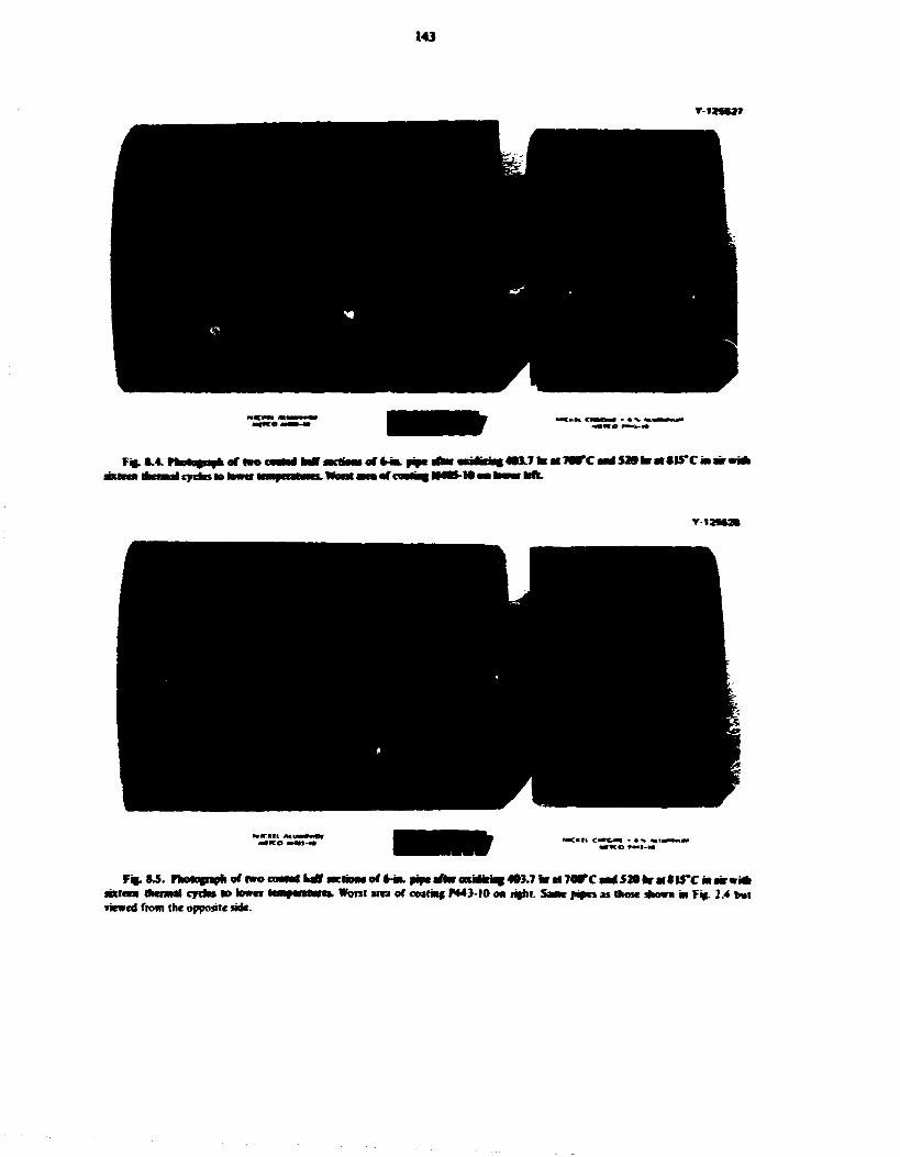
143
»-IMW7
HmmttyCimi
Y l
Fij. W . ffcotogiapli of two fixicca thermal cjrrto fo lower viewed from (he opposite lide.
C M M U T I ttwm$otK*.pif*th*oixmwilOi.l1m*1WCmiS10tmM*lS'CMmw*k Worst area of coating PM3-I0 ON rajht. Same pipes as those shown in F » 2.4 but

144
.••aria* at lop ja)J oxatalua of atrial andcr ipaBtd Note
•oanwC.A>p>]hihid.4-5x.
I 00101\ I • "o.25mm •
Fi$- 8.7. Pkotomioopapk of a typical edft of A* worn appearing m of pipe coaled with M405-I0. The oxide has separated from the metal during thermal cycling. As polished. |00x.

MS
* «
*fcK X < J &>m
the cootMf. As | i of * typical eipr of * c I
tion of the oxide and the differential expansion of the metal and oxide during thermal cycling caused the oxide lo spall.
Figure 8.9 is a photomicrograph of the worst- and best-appearing areas of the pipe section coated with P443-10. In the «orst-appearing .Tea the oxide has separated from the metal, but the remaining unoxidized metal was trucker than was the M4O5-I0 coating in similar areas (Fig. 8.0).
Figure 8.10 is a photomicrograph of an area where the oxide and coating separated but very little oxidation occurred below the coating. This possibly indicates that sone of the elements in the coating may have diffused into the base metal. A comparison of Figs. 8.6
i 0010 ill i
> a o f ripe cmmt l i t SMtS- l t . Onfeaoa occwerf beneath
and 8.9 shows that more unoxidized metal remained on the P443-I0 coated pipe section than on the M4O5-10 section in the worst of each case. Figure 8.11 is a photomicrograph of a typical edge of the best-appearing area of coating P443-10. There appears (o be very little oxidation of the metal at the coating-to-metal interface, indicating that the coating is an effective barrier to the inward diffusion of oxygen.
In this admittedly limited testing of oxidation-resistant coatings, it appears that the P443-I0 coating is superior to the M40S-I0 coating for this?pplication. It appears to give adequate protection when applied properly.
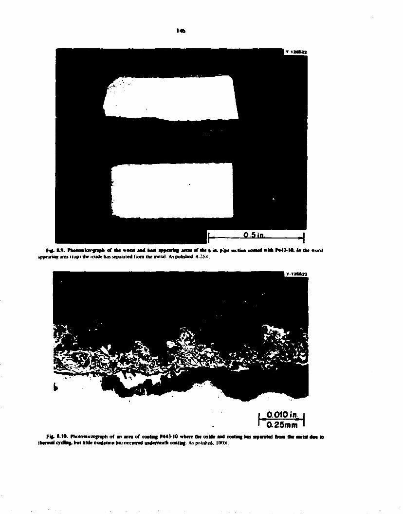
146
9 5 in, H Fig-1.9. Hwnowiiii'giaili of eat wont and bat appearing area* of dke t-aa. p>a* S K I M coated we* PMJ-ML in die worst
jppearinc. area I lop I the oxide has separated from the meiai. As polished. 4.25x.
h 0.010 if* 0.25mm
Fig. 8.10. Photomicrograph of an area of coring P443-I0 where dw oxide and coating has atparatad horn the Metal da* to thermal cycling, bul little oxidation ha> occurred imdcmtath coating. As polished. lOOx.
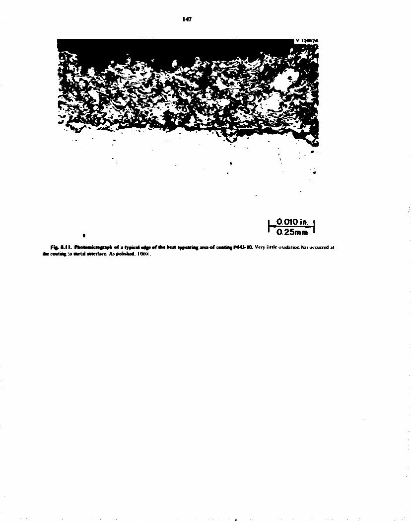
147
F « . t . l l . niUnmiip+holatTfiaftstott IMC c m t a f :o mcfat iMcrfjcc. As patched. IOIW.
I ^0.010 iit i » ' a 25mm I
• a of u»>tWf F443-M. Very i i l lk oxidaiior. has occurred j l

Part 4. Fuel Processing for Molten-Salt Breeder Reactors J. R. High tower. Jr.
Rut 4 deals with the development of processes for the isolation of protactinium and the removal of fission products from molten-salt breeder reactors. During this period studies were continued of the chemistry oi fuel reconstitute*!, studies of antnreMstatce hesMng for irse in a frozen-wall fluorinator. studies of mass transfer in agitated contactors using both molten-salt -bismuth and mercury-water systems, and installation of experimental equipment for a metal transfer experiment and a fuel reconstitution engineering experiment. Studies of mass transfer in open bubble columss (carried out in the Chemical engineering Research Program funded by the ERDA Division of Physical Research) were continued-Floor plans for an MSBR Fuel Processing Engineering Center were accepted, and the conceptual design was started.
In studies of the chemistry of fuel reconstitution it was found that the rate of reduction of UF, dissolved in fuel salt by hydrogen gas followed zero-order kinetics ai 550°C The rate constant was independent of uranium concentration, hydrogen flow rate, and hydrogen pressure. Hydrogen utilization in these tests was less than IT. The reaction appeared to follow first-order kinetics at 675°C The apparent reaction rate was increased by approximately two orders of magnitude and hydrogen utilization was increased to nearly stoichiometric by the addition oi platinum catalysts to the melt. Even trace quantities of platinum that combined with the gold reaction vessel liner were adequate to effect the same increase: thus practical application of this finding can be readily attained in the fuel reconstitution step.
Engineering experiments to study the steps in the metal transfer process for removing rare-earth fission products from molten-salt breeder reactor fuel salt are to be continued in new process vessels which duplicate those used in a previous experiment, MTE-3. Installation and preoperational testing of the equipment for this experiment, designated MTE-3P-. have been completed. The addition of the several salt <md bismuth
phases to the salt-bismuth contactor and stripper vessels is under way. Probably one to two months will be needed to complete these additions before starting experiments to measure the transfer rates for removal of rare earths from the fuel earner salt.
The seventh, eighth, and ninth tracer runs (TSMC-7, -8. and -9} were completed in the mild steel contactor installed in the salt-bismuth flow-through facility in Building 3592. Run TSMC-7 was nude at a low agitator speed (68 rpm) to help define the effect of agitator speed on the salt-phase mass-transfer coefficient under conditions where salt is not dispersed into the bismuth. The mass-transfer coefficient for this run was 0.0057 t 0.0012 cm/sec. which is 65% of the value predkied oy 'he Lewis correlation. Run TSMC-'l was made at a high agitator speed (244 rpm I to determine the mass-transfer coefficient under conditions where salt is dispersed into the bismuth and to determine if large amounts of bismuth and salt arc entrained in the other phase. The mass-transfer coefficient was 0.121 i 0.108 cm/sec. which is 178% of the value predicted by the Lewis correiation. The data suggest that when the phases are not dispersed, the effect of agitator speed on the mass-transfer coefficient is less than that predicted by the Lewis correlation.
Mass-transfer rates between water and mercury have been measured in a mechanically agitated contactor using the reaction
Pb 2*(H 20j +Zn[Hg| - Z n : * | H 2 0 ) +Pb[HgJ .
Data from a scries of five experiments have been reanalyzed using a model that was based on the assumptions that the reaction is instantaneous and irreversible and occurs entirely at the water-mercury interface in an at;?mp' to determine if an apparent change in mass-transfer coefficient during the execution of a run was due to the controlling resistance to mays transfer (.hanging from one phase to (he otner. Several inconsistencies were found between the model and the
148

149
experiment data. Several runs were made in the water-mercury contactor at an derated temperature Cv4U*C) to test the validity of the asvjrr.piiun thai the intertactal • -action is instantaneotis. Results from these tests were inconclusive.
Investqption was started to determine if potarography is a viable alternative metl?wi! for measuring mass-transfer rates in a stirred interface contactor using mercury and an aqueous electrolyte solution. Several electrolyte solutions were investigated but none was found to be entirely inert to mercury. Information found in the literature suggested that the Fe^-Fe** redox couple (using iron compiexed with oxalate ions) nay be suitable as an electrolyte for this application. Further tests will be performed to determine whether the iron oxalate electrolyte will produce suitable poiarograms.
Additional runs were made in a simulated iluorinator in which the vessel wall is protected by a frozen salt film and fission product heating is simulated by autorestst^nce heating. MSBR fuel salt was used in these tests. Successful operation was not achieved with the ekctrode in a side arm I necessary to avod corrosion when using fluorine). However, several apparently
successful runs were made with the Wcctrode «: die top of the vritical test section. It is believed that successful operation with the electrode in the side arm will he demonstrated in the next experiment, now being installed, which will use a circulating salt stream.
Measurements of mass-transfer rates m open bubble columns during CO- absorptwr in water were continued. Result* were extended to include the effects of liquid viscosity as well as effects of £*s and liquid flow rates on mass-transfer rates. Further improvements were made in the experimental technique, and aii p r f k u s data were critically reevaluated. The new oau vere combined with the most reliable data ft xn earlier work to produce correlations for estimating liquid-film nass-transfer coefficients.
Installation ot the fuel rcconstituuon engineering experiment in Building 7503 is expected to be com-pkted in early A«- J 1975. Details of the equipment for this experiment arc described.
A floor plan for the MSBR Fuel Processing Engineering Center has been developed, reviewed, and approved. The conceptual design of the building is under way. and an Engineering Job Plan for the design has been developed.

150
9. Chcmisti} of Fluorination and Fuel Reconscitution M. R. Bennett A. O. Keimers
The diemistry of the fluorination and fuel ^constitution steps of the reference processing plant flowsheet was reviewed in the preceding report.1 In previous experimental studies of the reaction of hydrogen with UF$ dissolved in fuel carrier salt, tiie hydrogen utilization and the rate of reaction were found to be low. 2
A detailed investigation of the reaction
2UF,(d) * Hj(g) - 2UF 4(d) • 2HF(g) (1)
was carried out during this report period. In a typical experiment, a 200-g charge of fuel earner salt (72-16-12 mole % LiF-BeF2-ThF4) plus about i to 4 wt % UF 4
was placed in a gold reactor and sparged with equimolar Hj-HF at 600°C for about 24 hr to remove oxide contaminants. Then the stoichiometric amount of gaseous UF« was contacted with the salt at 600°C to convert all the uranium io UF$. The temperature was then adjusted to the desired reaction temperature, and the salt was sparged with hydrogen to reduce the UFj to UF 4 . Samples of the salt were withdrawn at intervals and subsequently analyzed for U5* and U4* content by the Analytical Chemistry Division using the procedure described previously.2 Normally, the reducing gas flow rate was 40 cc/min for the first 4 hr and then 120 cc/min for an additional 4 hr. The reducing gas was either pure hydrogen <x an argon-hydrogen mixture.
In the first series of tests, at 550°C. the rate of reduction followed zero-order kine*ics. In this case, the rate of the reaction is independent ot the concentration of the reacting substance: thus.
di (2)
where n is the number of moles of substance undergoing reduction. I is the time in hours, and A' is the rate constant. From the integrated form of Eq. (2). it follows that a plot of the number of moles of UFj reduced vs time should be linear with a siope of A. Data from the experiments at 55oT are plotted in this manner (Fig. ° . i ) . All the data are consistent with
1. M. R. Bennett. L M. Perm. a.*j A. O. fCebncrs. MSR Program Srmiannu. Prop. Rep. Auf J I. 1974. OKNL-S0II. pp. 100 101.
2. M R. Bennett and I M Fern. / Inorg. Xucl. Cftem. 36. !285(I974)
zero-order behavior. The rate of reduction was independent of uranium concentration, hydrogen flow rate, and hydrogen partial pressure. The dau yield a rate constant of 0-00135 mole/hr.
The efect of temperature was evaluated in one test at 675°C. A pronounced increase in the rate of reaction was observed, and the data gave an excellent fit for first-order kinetics, a linear relationship of In \lf*\ vs time, indicating a probable change in the reaction mechanism or rate-limiting step at the higher temperature. In all the tests the hydrogen utilization was low «1%); most of the gas simply bubbled through the melt.
Dissociation of the hydrogen molecule to yield reactive hydrogen atoms is often a rate-limiting step in hydrogenztion reactions and would be consistent with the zero-order kinetics observed at 550°€. Therefore.
r*$ n j » 40ttfmHf -\ m 120ccArt* ' ' ' ' 1_
3 4 HOURS
Fig. 9.1. RedwctiM of dssaofeva UP, ttSSffC. Ten 2UR, . initial UF, concentration was ! .78 wt %, reducing gat was pure H,. Test SUR, " . initial UF, concentration was 4.60 »t T>. reducint gas was pure H,. Test 6UR. '•. initial UF, concentration was 2 32 wt % and reducing gas was H, -Ar (3347 mote?).
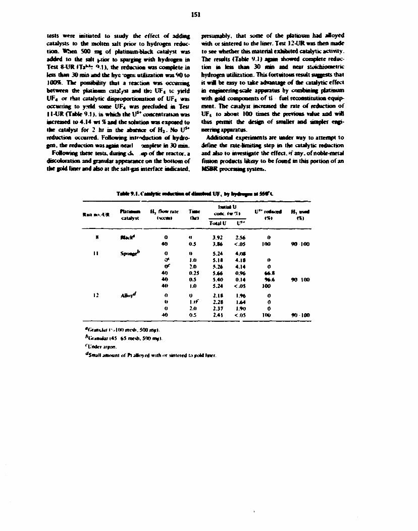
151
tests were initiated to study the effect of adding catalysts to the molten salt prior to hydrogen reduction. When 500 rag of pbtinum-bbdi catalyst was added to the salt yhot to sparging with hydrogen in Test 8-UR ITaNt ''.IK the reduction was complete in less dun 30 rain and the hyc-ogeti utiization was 90 to 100%. The possibility that a reaction was occurring between the platinum catalyst and the UF, tc yield UF 4 or that catalytic disproportionation of UF, was occurring to yreld some UF 4 was precluded in Test I l-UR (Table 9.1). m which the U 5 * concentration was increased to 4.14 wt % and the solution was exposed to the catalyst for 2 hr in the absence of H j . No Vs* reduction occurred. Following introduction of hydrogen, die reduction was again nearl omplete in 30 mm.
Folowing these tests, during ck op of the reactor, a discoloration and granular appearance on the bottom of the gold liner and also at die salt-gas interface indicated.
presumably, that some of the platinum had alloyed with or sintered to die liner. Test 12-UR was then made to see whether this material exhibited catalytic activity. The results (Table 9.1) again showed complete reduction in less than 30 mm and near stoichiometric hydrogen utiuzation. This fortuitous result suggests that it wil be easy to take advantage of die catalytic effect in engineering-scale apparatus by combining platinum with gold components of ti fuel reconstitution equipment. The catalyst increased the rate of reduction of UF, to about 100 times die previous value and will thus permit die design of smaller and ampler engineering apparatus.
Additional experiments are under way to attempt to define die rate-limiting step in the catalytic reduction and also to investigate the effect. >f any. of noble-metal fission products likdy to be found in this portion of an MSBR processing system.
r».I.C U F , * * stSMTl
Run no.-CR PblMwn I I , flow rate TiMc ImtialU
cooc. «w"> U"re4scc4 H,mcd catalyst tWCVftl <fc»> 1%) re> catalyst tWCVftl <fc»>
Total V U " 1%) re>
8 Hack* 0 0 3.92 2.56 0 40 OS 3.S6 <-05 100 90 100
I I Sp««e* 0 0 5.24 4.0S 0» 1.0 5.1* 4 18 0 ff :.o 5.26 4.14 0
40 0.25 5.66 0.96 66.8 40 0.5 5.40 0.14 96 * 90 100 40 1.0 5.24 <.05 100
12 ABoy*' 0 u 2.18 1 % 0 <• I.If 2.28 1.64 0 0 2.0 2.37 1.90 0
40 0.5 2.41 <0S 100 90 100
'GranUar I's 100 me*. 500 m$t Vrfjmdar i45 65 me*. 500 m*i. rt'ndcr arron. "Small amount of Pi alloyed with <>r sintered to foU later.

152
10. Engineering Development of Process Operations J R . Hightower.Jr.
10 1 DEVELOPMENT OF METAL TRANSFER PROCESS
H. C. Savage
Engineering experiments to study the steps in the metal transfer process fo* removing rare-earth fission producb from molten-salt breeder reactor fuel salt will be continued in new process vessels which duplicate those used in a previous experiment. MTE-3.1 Mechanically agitated contactors1 wat be used to achieve effective rates of transfer of the rare-earth fission products between the salt and metal phases.
Installation of the new equipment for the experiment, designated MTE-3B. in Budding 3541 was completed during this report period. The preoperational testing of the vessels, mechanical agitator, and associated auxiliary equipment is complete. Work is now in the initial stages of adding the salt and bismuth phases to the fuel-salt reservoir vessel and the mechanically agitated contactor and stripper vessels.
10 I 1 iMtaBstioa and Preoperational Tests of Metal Transfer Experinte** MTE-3B
Installation of equipment tor experiment MTF.-3B was completed during this report period. Figure 10.1 is a photograph of the process vessels with the heaters and <thermocouples attached. Figure 10.2 is a photograph of the completed experimental facility with the thermal insulation oi the vessels and with the mechanical agitators and all process piping and associated equipment installed.
On completion of the installation, all process instrumentation (cooling waici and purge-gar. flowmeters, pressure gages, thermocouples, temperature indicators and recorders, and 'he agiutor speed control units) were tested and calibrated. The carbon steel process vessels were then heated to 'v650°C. and the interior surfaces of the equipment were hydrogen treated to remove any residual o^des.
The charging of the several salt and bismuth phases (u the vessels is ROW under way. All the necessary
1. (hem Ttrii lux Annu. Progr Rrp Marth J I. IV7J. ORNMHH3. PP. 23 2$.
2. H. O. Weercn ci j | . . hnginrrnng Dcrrlopmrni Studiet for Molten Salt Rrerdtr Rett lor fforesmg So t. ORNI • FM-3259, (Occmhrr 197.') pp. 205 15.
materials are on hand. We have received the required fuel carrier salt O I 2 0 kg of 72-16-12 mole % LiF-BeFi ThF 4 ) from the salt production facility at Y-12. The bismuth, thorium, and lithium chloride are available from stocks used previously in experiment MTE-3. The charging of the salts and bismuth requires the temporary installation of the charging vessels along with the required heaters and temperature it Seating and control circuits. Careful procedures are followed to ensure that the correct amounts of each phase are added to the system and to prevent contamination of the salts and metals by oxides (air. water) during the charging operations. Probably, one to two months wHI be required to complete these additions before experiments are started to measure the rates of removal of rare-earth element* from the fuel carrier salt.
Currently we have installed the bismuth charging vessel and have hydrogen-fired it. added *v<90 kg of bismuth metal to the vessel, and sparged the bismuth with hydrogen to remove oxides; we are preparing to transfer the bismuth into the salt-metal contactor.
10.2 SALT-METAL CONTACTOR DEVELOPMENT: EXPERIMENTS WITH A MECHANICALLY
AGITATED NONDBPERSrNG CONTACTOR IN THE SALT BISMUTH FLOW-THROUGH
FACILITY
C. H. Brown. Jr.
In continued operation u a facility in which mau-transfer rates between molten LiF-BeFj-ThF4
(72-16-12 mole **) and molten bismuth can be measured in a mechanically agitated nondispersing contactor of the Lewis type. 1 A total of nine experimental runs have been completed to date. Results from the first six runs have been previously reported.4 Preparation for and results obtained from the seventh, eighth. and ninth runs (TSMC-7. -8. and -°. respectively) a.e discussed in the following sections.
In preparation for each of the three runs mad* luring this report period it was necessary to (I) add beryllium to the salt to adjust the uranium distribution coefficient. (2) contact the salt and bismuth by passing both
3. I. B. Uw». Chem. tug. Sti. i. 24* 59 M9S4). 4. J. A. Kkm ci j | . MSB frogrtm Semitw Ptogr. Rrp.
Aug. SI. /97*.ORNI.-SOM.pp. 114 UK.

1S3
PHOTO 2607-75
FfcM.I

154
PHOTO 0274-7S
Ffc. IO.J. Pkotafnpfc of N«ttl Tmafir E»»»riwwt WFE-M i*lrihho«

155
phases through the nutd steel contactor to ensure that chemical equilibrium was achieved between the salt and bismuth, and (3) add a sufficient quantity of I , 7 U tracer to the salt while it was in the salt feed tank. The experimental procedure that was followed in the first six runs has been previously reported.4 and was followed in the last three runs-
In run TSMC-7. salt and bismuth How rates were maintained at IS2 cc/min and 170 cc/rain, respectively, by controlled pressurization of the salt and bismuth feed tanks. The agitator was operated at 68 rpm for this run. At such a low agitator speed, no dispersal of salt into the bismuth was expected. Results from this run expand the data base for defining the effect of die agitator speed on the mass-transfer rate in the non-dispersed regime- The uranium distribution coefficient was measured to be greater than 97. which is greater than the minimum desired value of 20 which is necessary for decreasing the sensitivity of the measured data to small errors in the distribution coefficient for uranium.* The run was made without incident: however, the pre-nin phase equilibration procedure required three attempts before a successfu1 flow-through of the salt and bismuth was achieved. During the first two attempts, a leak developed in the transfer line from the bismuth feed tank to the contactor. This transfer line was completely replaced along with the associated heaters and thermal insulation.
Run TSMC-8 was done with salt and brsmi'th flow rates of 152 cc/min and 164 cc/min respectively. The uranium distribution coefficient was maintained at a high lewl (>40) fo> this run. The agitator was thought
5. J. A. Klein, tnfmetrmf Dmiopmcrit Studies for MollaiSMl Brrrdrr Reactor Procrnmi So. IS. ORNL-TM-4698.lMarch 19751 pp n
to have been operated at 241 rpm. which is high enough to produce mid dispersion of the phases in the contactor and therefore result m a high measured mass-transfer rat-*. However, results from this run indicated that little Cv.25%) of the 1 > T U tracer was actually transferred from the salt to the bismuth. Inspection of the magnetically coupled agitator drive assembly indicated that an accumulation of a highly vr> :ous carbonaceous material between the upper carbon bearing and the agitator drive shaft had prevented proper rotation of the shaft. The drive asembiy was cleaned of all foreign material, reassembled, and found to operate satisfactorily.
The ninth tracer run. TSMC-9. was performed as a repeat of the eighth run. Salt and bismuih flow rates were set at 169 cc/min and 164 cc/min respectively. The agitator was operated at 244 rpm during this run. A high stirring rate was maintained to determine the effects of dispersal of one phase in the other on the mass-transfer rate and to determine if large amounts of bismuth and alt are entrained in the other phase after passing through the small sciimg chamber in the contactor effluent line. The uranium distribution coefficient was greater than 47 during this run. No operating difficulties were encountered, and the run was performed smoothly.
Operating conditions along with mass-transfer results for runs TSMC-7. -8. and -'' are summarized in Table 10.1 along with the results from runs TSMC-2 through -6. The salt-phase mass-transfer coefficient was calculated using three diffeient equations derivec" previously from an overall mass balance aronnd the contactor4
based on three of the four measured concentrations of a given material in the inlet and outlet streams. The average measured mass-transfer coefficient is reported (Table 10.1) along with the corresponding standard deviation.
TaMr 10.1. liyumutut remits of i 'fame i
Run (cc/mm)
B smith flow (cc/mfo:
Slincr rale <rpml
»V Dl, Fraction of
tracer irauicrred*
Kt U.a i l K l
TSMC- (cc/mm) B smith flow
(cc/mfo:
Slincr rale <rpml
»V Dl, Fraction of
tracer irauicrred* Bated on V dasrd «n Zr
2 228 197 121 94 34 0.96 0.17 0.0059 0.0092 0 0083 • 0.0055 3 166 173 162 > 34 030 0.012 t 0.003 4 170 144 205 >I72 24 0.78 0.0S4 t 002 0.035 *0.02 5 219 175 124 > 43 24 0.35 0.0095 t 6.0013 O.OI63f 0.159 6 206 1*5 mo >|72 24 0.64 0.039 t 0.05 0.020 10.01 7 152 170 68 > 97 0.40 0.0057 t 0.0012 8 152 164 --0 > 40 0.25 0.0022 t 0.0010 9 169 164 244 > 47 0.94 0.121 » 0.108
'Fraction of tracer transferred * I C.IC.

156
The mass-transier coefficient measured in raft TSMC-7 is 0 J 0 0 5 7 ± OJOOI2 cm/sec. This value corresponds to 65% of the value predicted by the Lewis correlation.1 As previously discussed in the first of ?ect. 10.2, the agitator faieu to operate properly in run TSMC-8, which explains the rather low mass-transfer rate measured during this ran.0.0022 ± 00010 cm/sec-The measured mass-transfer coefficient obtained si run TSMC-9 n 0.121 ± 0.108 cm/ser. which corresponds to 178% of the Lew* correlation. As shown by the high value for the standard deviation, the three dcteruuna-lions for the mass-transfer coefficient in tins run differ gre&tiy. One possible explanation for litis is that the I , T U tracer balance arou&d the contactor showed closure to within only 50%.
A Lewis plot of the results from the $U runs which have produced meamngfid results is shown (Fig. 10J) . The nomenclature jsed in Fig. 10 J is:
k - individual phase mass-transfer coefficient.
¥ * kinematic viscosity. cm2/sec.
Re = Reynolds number (MD* iv). dimensionless.
D - stirrer diameter, cm.
N- stirrer rate. sec" 1,
subscripts 1.2 s phase being considered.
The values of die mass-transfer group based on uranium for runs 3 .5 . and 7 are between 33% and 65% of the Lewis correlation, white the values for that same group for runs 4 , 6 . and 9 are greater than 100% of the Lewis correlation (Fig. 103). In all but one case, the mass-transfer results based on zirconium are consistently sbshdy lower than the values based on uranium. This discrepancy is probably related to the inability to correct for the self-absorption of the 743 J7-fceV $~ resulting from 'he decay oi^^Zx in the solid bismuth samples.
Results from the runs performed in the nondispcrsed regime, runs TSMC-3, - 5 , and - 7 . suggest that the dependence of the mass-transfer group on the Reynolds number group is slightly less than that predicted by the Lewis correlation. The exponent appears to be closer to 1.0 than to 1.65. This is consistent with the data of Lewis, which show that for a single aqueous-organic system the exponent on the Reynolds number group is more nearly I JO than i.65.
Probably, at a stirrer speed between 160 and 180 rpm the entrainment of salt into the Ismuth begins to occur and the apparent increase .n mass-transfer coefficient at
, ' / • i i 11 m i t i n i m l _ _
c * m t K t o r w i * ' ' ' l ^ ^ * , Z i k a c c n . c o a * « * t o r J M v a ) a e > fiktti ky uw Lewis oindBaan.
higher agitator speeds is a manifestation of an increase in the surface area fa. mass transfer due to surface motion. This effect is verified by the high mass-tramfer rates measured in runs 4. 6. and 9 . Experiment; with water-mercury and water-methylene bromide systems indicate abo that phase dispr^w occurs initially at agitator speeds near 180 rpm.
It is possible that at higi. aviator rates ( > I 7 0 rpm) some salt or bismuth is entraii Mi in the other phase and is carried out of the contactor. This effect is detectable i f sufficient settling time is not available between the times when the salt and bismuth exit from the contactor and when the flowing stream samples are taken. Figure 10.4 shows the result* of analysis for beryllium in the bismuth flowing stream samples taken in runs TSMC-5. -6. and -9. which were performed at 124. 180. and 244 rpm respectively. The concentration of Be in bismuth samples fell within the range of 10 to 464 prnn. A concentration of I pom of Be in bismuth corresponds to I.I X 10"* vol % salt entrained in bismuth.
It is assumed that any beryllium present in the bismuth is due to entrainment of salt in the bismuth phase. Even when dispersion is suspected, there is

157
lyiarii ttjme.
essentially no more beryllium, and hence no more salt, present in the bismuth stream than when the phases are not dispersed (Fig. 10.4). In rhe middle of a run there does not appear to be an effect of agitator speed on the amount of beryllium in the bismuth. The effect of salt entrainment in the bismuth would be most significant in the metal transfer process, where the presence of fluoride ions in the lithium chloride at concentrations above several mole percent decreases the separation between the rare-earth elements and thorium. Thus, it appears that the LiCl-Bi contactors can probably be operated under conditions of mild phase dispersal.
Analyses of bismuth in the salt samples could not be obtained. However, no gross amounts of bismuth were indicated from the weights of the salt samples. It b possible that the increased mass-transfer rate afforded by mid dispersal of the salt and bismuth phases in a stirred contactor cat be taken advantage of without imposing any detrimental effecu to the reactor vessel or adding a large burden to the bismuth removal step. A series cf runs at high agitator speeds is planned to investigate more closely the magnitude of enirainment effects in this type of contactor.
10 J SALT-METAL CONTACTOR DEVELOPMENT EXKRMENTS WITH A MECHANICALLY AGITATED NONOBTERSINC CONTACTOR
USING WATER AND MERCURY
C.H.Brown. Jr.
The reference flowsheet for the proposed MSBR processing plant calls for the extraction of rare-earth
elements from the fluoride fuel carrier salt to an intermediate bismuth stream. One devke being considered for mis extraction is a nvechaakaBy agitated noMKpersing contactor in which bismuth and fluoride salt phases are agitated to increase the .^ass-transfer rate of rare earths across the salt-bismuth interface. Previous reports* * have indicated that the fottowsj reaction in the water-mercury system is suitable tor sanidating and studying mass transfer in the water-iaeiciuy system, which approximates molten salt-bismuth systems:
rV'lHjO) •Zn |Hg | -Zn , *IHiO | *Pb|Hg|. (If
A large amount of data has been reported* for die water-mercury system under die assumption that the limiting resistance to mass transfer existed entirely in the mercury phase, as suggested by literature corrda-tkms-*
A series of experiments was previously described'* which was designed to identify the phase in which the controlling resistance to mass transfer occurs, in these experiments it was noticed that die mass-transfer coefficient appeared to vary during die course of the run if the initial concentrations of zinc in die mercury phase and Pb 2 ' in die water phase were not equal. The value of die mass-transfer coefficient would change rather abruptly after die experiment ran about 12 to 18 min. During this report period the following has been accomplished: (I.1 data •catalyzed from the experiments which were done in the water-mercury contactor in an attempt to determine if the apparent change in mass-transfer coefficient was due to the controlling resistance changing from one phase to the other during the course of an experiment. (2l further experiments done in the water-mercury contactor, at an elevated temperature, to verify the assumption tra: the reaction given by Eq. (I) is instantaneous, and (i) experiments begun to determine if nglarography is a workable alternative method for determining individual water-phase mass-transfer coefficients in the nondtsprismg stirred interface contactor.
6. w. R. HoNtiey. MSR hvpwm Sinumn. hop. Krp. Aug SI. /974.0*NL-50II.p. I*.
7. J. A. KfcM. tngmtthmg Deretopmmt Sftjdw* for MolltiiSMl trredtr Rnctor Procesm* So 14. ORNL-TM-401! (in ptcpenlmM.
9. J. A. Klein. Eapuatm Dneiapmrtu SnttHa for MoitmSMl trttder Rmeur Prvta+m Mo. IS. ORNL-TH-4019 (in preparation).
9. J.l . L*w».CVm.£>f.Srt. J. 248 259U954) 10. C. H. ttown. Jr.. MSK PKOJWM Srmtmui. P*OT Hep.
Am H• 1974. ORNL-5011. pp. 119-122.

1SS
103.1 Tkewy
As was previously reported.1* the reaction being studied. Eq. (I) . is considered to be a fast irreversible ionic reaction which occurs entirely at the mercury-water interface. The rate of transport of reactanis from the bulk phase to the interface where thev react is given by:
• \ n ^ B * H f * C t a " . , - • < * • • ; » • <2)
where
k = indivkhul phase mass-transfer coefficient, cm/sec.
X = rate of mass transport to the interface, g, sec.
A = interfacial area, cm 2 .
C - concentration. g/cm*.
B = bulk phase.
i = interface
and Hg- H 2 0 refer to the phase being considered. Since one mole of Zn* is equivalent to one mole of Pb2* according to Eq. (!). .Vpb** s v Zn* Substituting Eqs. (2) and (3) into this expression yields the following equa^iy;
s * u . n l C , f c
: * . -CBUUJ. (4>
As earlier reported." if the controlling resistance to mass transfer is assumed to occur in one phase, the interfacial reactant concentration in that phase is small with respect to the bulk reacfaof concentration. In the experiments winch have been done. 1 0 it may be possible for the limiting resutanvs to mass transfer to change from one phase to the other during ft* course of an experiment. At this transition point the following equiJity exists, since both interfacial reactant concentrations are small with respect to their bulk phase concentrations:
*HiCZi» 0.» "*HjO C Pb J *^ (5)
If the controlling resistance to man transfer is in the aqueous phase, two equations, one in terms of measured concentrations of Pb** and one in terms of measured concentrations of Zn1*. can be derived:
In <W*«'> kH*W* = — - — t . <V*<0)
kH*W* = — - — t .
In Kfb^oi cla^n\ *HjO / l
In
I fpb-^o. J V H 2 0
where
V - volume of phase, cm 1 .
t = time. sec.
<b»
17,
and quantities in parentheses indicate times. If the merciry phase contains the controlling resist
ance to mass transfer, two other equations, one in terras of measured concentrations of Pb2* annd one in terms of measured concentrations of Zn2*. can be derived:
, [ cZn*IO, C p ^ l O l + C n , 2 ^ ,
C 2 q e ( 0 » kHg* t, <8>
Hg
,n[Qn»<0 CZm^n] * " < <u> C 2 n o(0> * ' H r
Equations (6). (7). (8 >. and <«» are all of the form
v - ml. (10)
where y is the naturci logarithm of a concentration ratio, m is a mass-transfer coefficient times the inter-facia! area divided by the phase volume, and t is time, which indkates that a plot of the logarithm of the concentration ratio vs time should yield a straight line with the slope being proportional to the mass-transfer coefficient. If the control of mass transfer switches from one phase to the other during an experiment, then the slope of the line mentioned above would change.
Equation (5,: can be used with experimental values of *Hg- *HaO- a n d concentrations of Zn1* and Pb1* evaluated at the lime of apparent change of mass-transfer coefficient and at the beginning of the experiment, to determine the phase in which the limiting mass-transfer resistance occurred at the beginning of the run. The firs, step in the determinaticn of the mass-transfer limiting phase at the beginning of a run is to find the pair of individual phase mass-transfer coefficients, one before and one after the transition point.

159
which satisfy Eq. (5) with the bulk reacunt concentrations evaluated at the transition point. Two combinations of mass-transfer coefficients are possible, giving Eq. (5) the following two forms:
. « l t _ _ . ( 2 > r i 'Hg^Zn^-'H.ot-Pb
tit I l l ; * H , 0 C i
2* Pb tr
( ID
(12)
where superscripts I and 2 refer to the slope in Eq. (10) before and after the transition, respectively, and the subscript tr refers to the transition point. Equation (6)
iX«> L«I> or (7) is used to determine * H ' Q and *ii"n- ""d &1-(81 or Eq («»> is used to determine k\}* and V^'f
Once it has been determined from this test which pair of mass-tiansfer coefficients is applicable to a particular run. the mass-transfer limiting phase at the beginning of the run may be determined by comparing the magnitude of the product of mass-transfer coefficient and bulk reactant concentration at the beginning of the run. The individual phase mass-transfer coefficient in the limiting phase times the bulk reactant concentration in that same phase must be less than the same product in the nonlimiting phase. Therefore, if Eq. (11) is satisfied, then the direction of the following inequality determines the initial mass-transfer limiting phase:
M l *H« C Z n • ( O ^ ^ O ^ P b 2 * ^ 113)
and similarly il Eq (12) is satisfied the limiting phase is determined by the direction of the inequality
*2t i l l *H,Qn°<<>><*rM><V-< 0> < 141
10.3.2 Experaneatal Results
Five experiments were run in the water-mercury' contactor to determine if the apparent change in mass-transfer coefficient was due to a shift in the controlling resistance from one phase to the other during the course of an experiment. The initial mercury-phase zinc concentration was held constant at 0.1 M. Phase volumes and agitator speed were also held constant at 1.8 li.ers and M 50 rpm respectively.
The data obtained from these five runs were anilyzeH with the equations given in the previous section. The results of this analysis for determination of the pluse in which the limiting resistance to mass transfer occurred at the begnning of each run are given in Table 10.2, along with the measured value of the mass-transfer coefficient in the limiting phase.
The results given in Table 10.2 indicate that, in the runs made with the initial aqueous-phase lead concentration equal to or less than the initial mercury-phase zinc concentration, the limiting resistance to mass transfer was initially in tl»e mercury phase. For the runs made with an initial lead ion concentration greater than the initial zinc amalgam concentration the aqueous phase controls mass transfer. The results from run 148. in which the initial reactant concentrations are nearly equal, are difficult to analyze because only a slight change of slope in a plot of Eq. (10) was detected.
In runs I4S and 149. the initial lead ion concentration was low with respect to the zinc amalgam concentration. This would indicate that the aqueous phase should initially contain the limiting resistance since the initial lead ion concentration times the mass-transfer coefficient should be less than the initial zinc amalgam concentration times the mass-transfer coefficient in that phase. Similarly, in runs 146 and 147
T*fc I0J . Mor i hatf ion concentratm and mau-master coefKcimti in die abate • * • • > coanjaiag the
r » H U M ttaaafo for ran* 145-149
Initial Ma*vtran«fer coefficient in the phase conirolline mass transfer
Run number convent ration i mtully (cm/sec) convent ration
*H« * H , 0
145 0.0197 0 0012 149 O.0192 0.0013 148 0.0960 0.0026 146 0.141 0.0061 147 0. IM 0.0046

160
the initial lead ion concentration was large with respect to the zinc amalgam concentration, which would indicate that the mercury phase should initially contain the limiting resistance to mass transfer.
According to the model developed, if the aqueous phase initially contains the limiting resistance to mass transfer the following inequality is satisfied:
* H g C Z B # < 0 > > * H 2 O c l > b 2 * ( 0 ) . (15)
During an experimental run, the inequality given by Eq. (15) should always be satisfied, since the lead ion concentration decreases, with an equal decrease in the zinc amalgam concentration. This indicates that the aqueous phase should control mass transfer throughout the run with no change of slope, corresponding to a change in the controlling phase, in a plot of Eq. (6). The parameters of Eq. (6) are plotted for the data obtained in run 146 (Fig. 10.5). A definite change of slope is recognizable at a value of the abscissa (time) between 15 and 18 min, which would indicate a change in the phase containing the limiting resistance to mass transfer.
The value of the individual phase mass-transfer coefficient should be the same for all runs since the agitator speed was not varied. However, the experimental results indicate that the measured mass-transfer coefficient for the mercury phase in runs 145.148. and 149 increased in direct proportion to the initial lead ion concentration (Table 10.2). Similarly the values
mm. ••• n-mto 12
11
10
a* an a?
a« as a« as az ai
ao <
ai
ao < > TWC IM)
f'%. 105. Logarithm of ike concentration ratio n tine for ran 146 in the wslcr-mercnry contactor.
reported for the aqueous phase mass-transfer coefficient in runs 146 and 147 vary inversely with the initial lead ion concentration.
Several runs were made in which the temperature of the contactor and reactants was raised to approximately 40°C. The results from these runs are inconclusive because it was found that at this elevated temperature, hydrochloric acid, which was present in the aqueous phase to prevent oxide formation at the mercury surface, reacted with zinc to form zinc chloride. This makes the mass-transfer analysis more difficult by introducing a competing reaction. Also, depletion of the acid caused formation of a spongy lead compound on the agitator blades and at the water-mercury interface.
From the results presented here it is clear that sufficient uncertainty exists in this method of determining mass-transfer coefficients in water-mercury systems that another method should be developed. The next section discusses initial attempts to develop such a method.
10.3 J Poinoguphic Determination of Mass-Transfer Coefficients
Polarography has been suggested as an alternate method for determining the water phase mass-transfer coefficient in the witer-mercury contactor. The necessary experimental equipment has been assembled, and preliminary tests have been made to determine a suitable redox couple and an electrolyte which will produce the desired polarization curves while being chemically inert to mercury.
1033.1 Theory. The polarographic technique ior determining mass-transfer coefficients involves oxidation of a reduced species or reduction of an oxidized species at an electrode which is at a condition of concentration polarization. One system which hjs been previously studied" is the reduction of ferricyanide ions at a polarized nickel electrode. As ferricyanide was reduced at the cathode, ferrocyanide was oxidized at the anode. There was no net consumption of chemicals or change in the composition of the electrolyte solution. Polarization of the cathode can be accomplished in one of two ways: cither the cathode surface area is made very large with respect to the anode surface area, or the concentration of the oxidized species is made very small with respect to the reduced species.
II. i. S. Walv>n. "A Study of Detached Turbulence Promoters for Increasing Mass Transfer Rales in Aqueous Chemical How." Ph.D. Thesis, University of Tennessee (1967).

161
The aapukm of an ion in both electric and concentration fields is described by the Nemst-Planck equation:
f2 = Z X v O ^ ^ ) . (16) RT
where
C=concentration of reacting ion, moles/liter,
@ = flux of the km, motes cm" 2 sec" 1.
D = diffusion coefficient, cm 1/sec,
Z = valence,
R - gas constant,
T = absolute temperature, °K,
F- Faraday's constant. C/mole,
• = electric potential. V.
The first term in the expression represents the contribution of ordinary diffusion to the flux, and the second term represents the contribution of etectromigration. A large concentration (relative to that of the reacting ion) of an inert electrolyte alters the dielectric properties of the solution so that the potential will decrease smoothly across the region between the electrodes while the concentration drops sharply across the thin polarized layer near the cathode. Thus, the term containing the electric potential becomes relatively small and
Then the current flowing between the electrodes is a measure of mass-transfer rates governed by ordinary molecular diffusion. This current is sometimes called the diffusion current.
The impressed current is proportional to the mass flux across the stagnant layer between the bulk electrolyte and the polarized cathode, and the mass-transfer coefficient is given by:
* = . I
ZAFCm
(18)
Q*DVC. (17)
where
k =mass-transfer coefficient through the film.
cm/sec,
/ = polarization current. A,
A - area of the polarized electrode, cm 1 , Cg - concentration in g-moles/cm3 of transferring
species in the bulk liquid.
Thus, it is possible to determine mass-transfer rates from the bulk electrolyte to the electrode surface using experimentally determined values for /, CB. and A.
1033.2 Experimental equipment. The experimental apparatus which will measure mass-transfer rates in the water-mercury stirred contactor is shown schematically in Fig. 10.6. The equipment consists of a 5 X 7 in. Plexiglas contactor which was used in previous work with the water-mercury system. The mercury surface in the contactor acts as the cathode in the electrochemical cell. The cathode is electrically connected to the remainder of the circuit by a '4-in.diam stainless steel
OftNL OWG 75-«l3
X.T PLOTTER
M It
Oil./*. 10 MITTS
0. C POWER SUPPLY O-IOV 0-100
• 3 SUPPLY
VARIABLE SPEED DRIVE MOTOR
WATER-MERCURY ELECTROCHEMICAL CELL
Fig. JO. 6. Schrmrtic contactor.
m of tin «qeipnwnt nsed to i i pDttrizafio* carrmts in dw wiwumouy ckctrocbcmkil c d

162
rod which is electrically insulated from the electrolyte phase by a Teflon sheath. The anode of the cell is suspended in the aqueous electrolyte phase and consists of a ',4-in-thick piece of nickel sheet which is formed to fit the inner perimeter of the Plexigfcs cell. The current through the cell is inferred from the voltage drop across a 0.1 ± 0.0005 J2. 1C-W precision resistor. The voltage drop across the resistor is recorded as they coordinate on a Hewlett-Packard x. y plotter. The x coordinate on the plotter is produced by the direct current voltage supplied to the cell from a 0 -10 V. 0 - ! 0 A Hewlett-Packard dc power supply.
1 0 3 3 3 Experimental malts. Several different electrolyte solutions have been evaluated subject to two different criteria: the electrolyte must be chemically inert to mercury, and it must be possible to polarize the mercury surface with the given electrolyte. The different electrolytes that have been examined are (I ) potassium ferrocyanide and potassium ferricyanide with a sodium hydroxide supporting electrolyte. (2) potassium ferrocyanide and potassium ferricyanide with a sodium chloride supporting electrolyte. (3) potassium ferro- and ferricyanides with a sodium nitrate supporting electrolyte. (4) ferrous and ferric sulfate with a sodium hydroxide supporting electrolyte, and (S) ferrous and ferric sulfate with sulfuric acid as the supporting electrolyte.
None of the electrolytes mentioned above met both of the required criteria. The ferrous and ferric sulfate system with sulfuric acid as the supporting electrolyte was the only combination which proved to be chemically inert to the mercury cathode. However, it was found, that the ferric ions reacted with the mercury cathode at a voltage less than that required to polarize the mercury cathode. This phenomenon has been previously discussed in the literature by Kolthoff and Lingane.12 who reported that the following reaction occurs when ferric ions are contacted with mercury:
2Fe* + 2Hg = 2Fe2* + Hgj 2* . (19)
making the half-wave potential of ferric ions not directly measurable.
The reversible oxidation and reduction of ferrous and ferric ions i w e been reported7 to be feasible when the iron ions are complexed with excess oxalate ions. This system will be examined in detail for potential application to the experiment under development.
12. I. M. KotthofT and J. J. Lindane. Polarography. 1st ed . Inter*. ienceU 94 <>>.
10.4 CONTINUOUS FLUORINATOR DEVELOPMENT
R. B. Lindauer
The investigation is continuing into autoresistence heating as a heat source for the nonradioactive demonstration of frozen-salt corro*"H» protection in a continuous fluorinator. Successful operation in a simple vertical test vessel using 66-34 mole % UF-B«Fi • AHT-2) ict> been reported.1 3 A fluorinator mockup (AHT-3 • that was designed to test an electrode in a side arm out of the fluorine path has been previously described.' * ' 5 Initial test runs in the equipment using MSBR fuel salt. LiF-BeF,-ThF4 (72-16-12 mole %). have also been reported. 1 5 '* Additional runs were made with this equipment as designed but with little success. Subsequendy several apparently successful runs were made with fuel salt but with the electrode in the vertical section instead of in the side arm.
A circulating salt system is being installed to complete the frozen wall formation tests planned before tests are started using fluorine. This test (AHT-4) uses the same test vessel as AHT-3 but with an argon gas lift to circulate the salt. The salt will be introduced through the electrode in the side arm. Probably, the circulating salt will reduce wall-temperature differences throughout the test vessel during the formation of the frozen salt film, thus maintaining a molten core until a continuous electrically insulating film has been formed on the vessel wall.
i 0.4.1 Autoresistance Heating Test AHT-3
As previously reported.15 this equipment was built and five unsuccessful runs were attempted before the MSR Program was terminated in the spring of 1973. Four more runs were also attempted n the previous report period, ending with the melting off of the lower 6 in. of the 'A-in. Inconel electrode. Theiefore the initial work in this period was concerned with draining
13. J. R. Hwfctower. Jr.. Engineering development Studies for Molten Salt Breeder Reactor Processing Mo. 16. ORNL-TM-4010 (in preparation).
14. J. R. Hqditowc, Jr. Engineering Development Studies for Molten Sell Breeder Reactor Processing \o. 17. ORNL-TM-4178 (in preparation).
15. J. R. Hnthtnwer. Jr. and R. M OniTitc. MSR Program Semunn. Progr. Rep. Aug 31. 1974. OKM-5011. pp. 122 127.
16. R. M. ("ounce and J. R. Hifthtower. Jr.. Engineering Development Studies for Molten-Salt Breeder Reactor Processing \o. IS. ORNL-TM-4698. p. 37.

163
the electrode side arm and recovering the melted portion of the electrode. A drain line was installed between the bottom of the side arm and the vertical section of the test vessel, and the side arm was drained-A new electrode was fabricated of Vin. sched 40 nickel pipe with a 5-in.-k>ng section pointing up the slanting section of the side arm. This is the configuration planned for the circulating system of AHT-4 to avoid impingement of the molten salt directly on the frozen wall The other modification made at this time consisted of the installation of %-in. stainless steel cooling coils on the test section. Air, with a small amount of water to increase the heat capacity, was used as a coolant. This eliminated the need to remove (or loosen) the insulation during each test and reduced the cooling time.
Seven runs were made with the side arm electrode, but a uniform, nonconducting salt film could not be formed before complete freezing of the salt occurred. During tiie most successful of there runs. AHT3-i5,an autoresistancc power of 1130 W was reached. The resistance between electrodes was 1-3 ft. However, a short occurred, and the power could not be increased to that required to balance the heat loss.
To demonstrate that stable operation could be maintained wiih the 72-16-12 mote % LiF-BeFi-ThF4 salt, an electrode was installed in the top of the vertical section of the test section, and the salt in the electrode side arm was frozen. This shortened the length of the test section from 44 to 24 in. and eliminated the side arm junction from the current path. Reasonably steady-conditions were maintained but with a much lower resistance than anticipated. The resistance across ihe 2-ft test section was M).| ft. indicating that the resistivity of the salt was about one-third of the 0.7S ft-cm value stated in the literature.17 Salt from the test vessel could not be transferred with a frozen wall present in the test section to verify the thickness of the salt film. It can be inferred that the resistivity was probably between O.i and 0.2 Q-cm (Fig. 10.7). An average film thickness of % in. is probably necessary to prevent shorting, since the film is not noimily uniform. This implies a resistivity of 0.2 ft-cm or greater to account for the resistance (0.1 ft) measured in run 21. Similarly, if the resistivity were less than 0.1 ft-cm. the average film thickness in run IS would have been 2% in. or greater, and current blockage by freezing would probably have occurred at some point.
lt.4.2 Design of E q w p f l for Autoicsistaace Heaug Test AHT-4
The next equipment tc be used in tl* development of the frozen-wall fluorinator consists of a circulating salt system using autotesistance heating. The flow diagram for the equipment is shown in Fig 10.8. Salt is
"
TEST SflCTOI
MOUSE FUN TMOMCSS (Ml
Fig. 10.7. Reactivity n mm thickness for rent AH1>I5 and AHT3-2I.
17. G. D. Robbin* and A. S. Galbnier. MSR Pro&am Semionn. ffogr. Rrp. Aug. 31. /97fl.ORNL-4622.p. 101.
Fig. 10.8. Flow diajran for aatorcsirtaMCf nesting test AKT-4.

164
circulated from the surge tank to the gas-liquid separator by means of an argon gas lift. The salt then flows by gravity lo the test vessel via a special insulated flange and the electrode. The salt leaves the bottom of the test vessel and passes t»v >ugh a heat flowmeter before being returned to the surge tank through another insulated
flange. The insulated flanges are water-cooled to permit the use of Teflon gaskets. The bolts are insulated by a Bakdiie sleeve and Teflon washers (Fig. 10.9). A deflector is located in the return line at the point where it enters the surge tank to prevent short-circuiting across die liquid stream (Fig. 10.10). The surge tank
WOTO 0039-75
Fu> lv.9. Etactnany
PHOTO 0042-75
t
%
1*
FJE. IW.IO. Swv^ lawk Met name Aowinj Maters a*d a l l deflector.

165
and separator are therefore at ihe ante electrical potential as the ek.lrode and must be insulated from the equipment supports. Gas lines to these two vessels have insulated sections. An air-cooled freeze valve is located in the line between the separator and the test vessel to make it possible to presume Ihe lest vessel and transfer the molten salt from the test vessel to die surge tank after a ran to determine the thickness of the frozen salt layer. The individual equipment pieces are described next.
I0.4.2-I Test vessel. The test vessel is t ie same one used in AHT-3. Inspection of the vessel after drainmg salt from the last run revealed about II liters of material which failed to drain. This was due partly to runback but mainly to plugging of ihe side arm drain line with impurities (oxides and structural metal fluorides) accumulated over the past two years of operation- The bottom 6% in. of die vesse! tru fined with salt and was cat off. Another cut was made below die electrode side arm to allow submergence of the vessel in an open vat: there it was contacted widi a hot C\.200°F) 63 oxalic acid solution for seven days and hot ammonium oxalate for two days. The solution was changed two times durit^ the cleaning operation. Cleaning was complicated by the sail remaining in the electrode side arm. which prevented removal of the electrode snd flange. This prevented circulation of the oxalic acid through the side arm. After the electrode was broken loose, the residual sail was broken up manually, and decontamination was completed. New heaters and cooling coils have been installed on the test vessel for belter control of temperature. The electrode (Fig. IO.l I Ms similar to lhal used in AHT-3 but has an open-end pipe for sail flow.
10.422 FhMride salt s a f e tank (Figs. 10.12 and 10.13). This is a dual-diameter vessel having a lower section of 6-in. sched 40 nickel pipe 46 in. long and an upper section of %-in.-thkk nickel 24 in. in diameter by II in. high. The long 6-in.-Uiam section provides ample submergence for the gas lift, while the large-diameter upper se rtion provides sufficient capacity to contain the sail from the entire system. A sensitive (0.20 in. of water) liquid-level instrument in the large-diameter section will indicate any unusual buildup of salt at tht lop of ihe test rosel or separator as well as measuring the volume of the dozen salt film after a lest run.
I0.4.2J Cat-tiqnd separator. This is an 8-in-diam. 12-in -high cone-boitom nickel vessel containing an 8-in.-decp !?ver of Ynrkmesh nickel demisicr. Two baffle plate* are located below 'he Yorkmesh for separation of ihe bulk of the sail from (he argon-salt
mixture from die gas lift- A differential pressure instrument will detect any liquid buildup in the bottom or any excessive pressure drop across die separator. A thermowel that is located in the Yorkmesh will be mamtained above the melting point of the salt.
It.4.2.4 Heat fcw—tu (fig. 10.14). The sail leaving the test vessel passes through a 28«- long section of 2-in. nickel pipe containing a cartridge herjer. Heat loss from the flowmeter will be balanced by external heaters. The internal beater -an be operated on either 120 V (750 W) or 240 V (3000 W) dependng on die salt flow raw. A temperature rise of about 10°C through the flov meter will indicate a salt flow rate of either 0.9 or 3.6 liters/mm depending on the voltage.
1*5 FUEL RECONSniUnON DEVELOPMENT VvSTAUJVllOMOFEQUVMENTFOiLAFlJEL
WECONSinUTKNINGWiltKShGlXruattEm
R. M. Counce
The reference flowsheet for processing tiie fuel salt from a molten-salt breeder reactor is based upon removal of uranium by fluorinalion to UF« as the first prjcessing step. 1* The uranium removed in this step must subsequently be returned to die fuel salt stream before it returns to the reactor. The method for recombining the uranium with the fuel carrier salt (reconstituting Ihe fuei salt) consists of absorbing gaseous UF* into a recycled fuel salt stream containing dissolved UF 4 by using the reaction:
UF*(g>+ UF 4(d) = 2UF,(d>. (20)
The resultant UF 5 would be reduced to UF 4 with hydrogen in a separate vessel according to die reaction:
2UF,(d) + Hj(g) = 2UF 4(d) • 2HF(g). (21)
Engineering studies of the fuel reconstitution step have been started to provide the technology necessary for the design of larger equipment for recombining UF« generated in fluorinators in ihe processing plant with ihe processed fuel sail returning to the reactor. During this report period, equipment previously described was fabricated and is being installed in the high-bay area of Building 7:r03. This report describes 'he details of the cxperimeniil equipment.
I». Chrm. Tech. Div. Amu. Progr. Rep. Mmrh 31. 1972. ORNI.-47W.p. I.
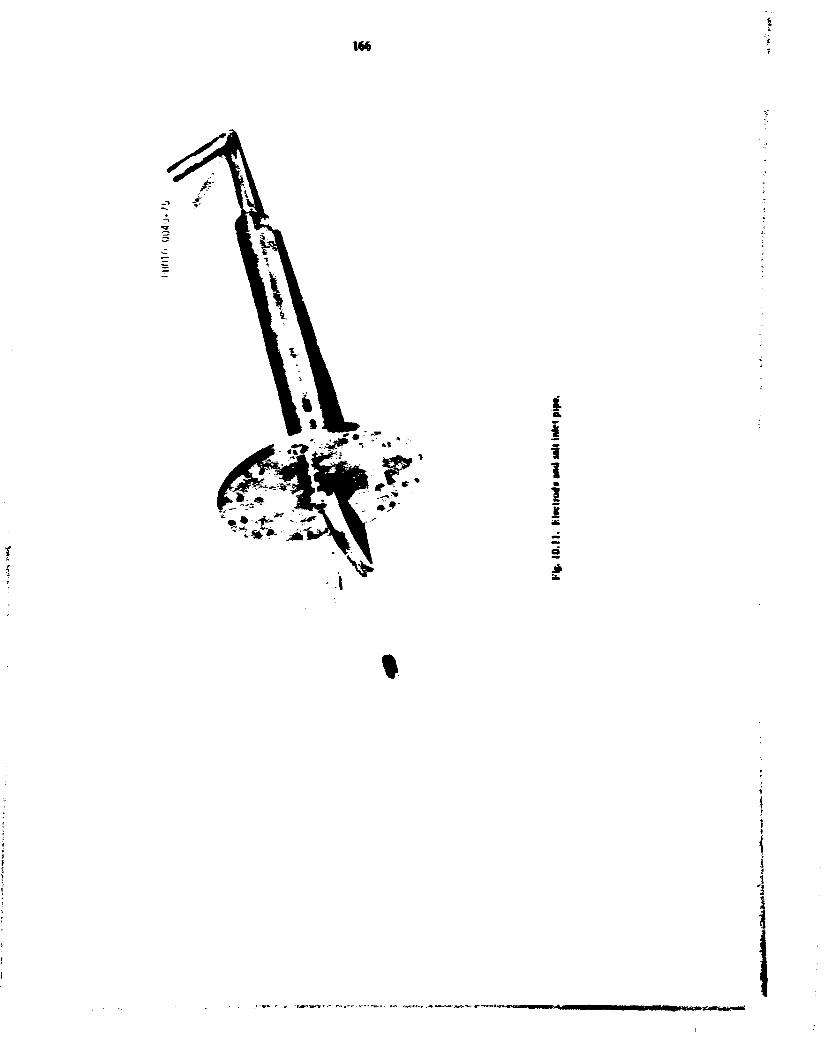
l t t
I i i i I
1 i
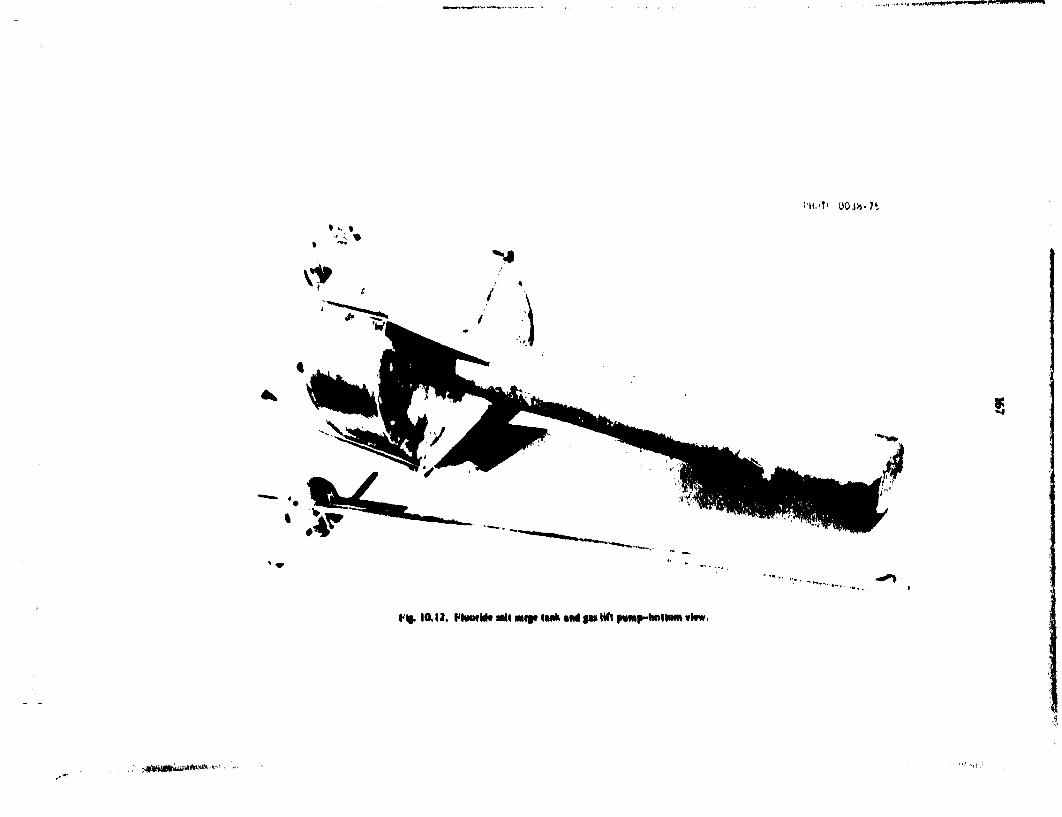
, . ,., ;.,-, «**nim. W " "!• 1 , 1 — H » U W » »"<II»'W
i'H.'T' oo in-n . • s «
5
V%. 10,12. FhmfMf aril wift (M* mi f u Ufi pimH"*!*"* vt»w.
^mm*ai**^m'<

tfa
in i
O o o
i
I
I 2 o

»» »w— nj»i '•«! j j i M M > J W W anjW-' WHiH.'gWL'jWiWQWTBl*
169
o j
o
/ '
i ( i .
!

170
Factors important in carrying out reactions (20) and (21) wul be studied in experimental proces equipment described biter in this report. The parameters that are expected to be of interest are gas flow rates, liquid flow rates, and reaction temperature. Results will be deter-mmed by analyzing the efficiency of UF« absorption for reaction (20) and hydrogen utilization for reaction 121) under various operating conditions. These quantities wnl be deterHuned by component mass balanm around the respective reaction vessels. The major components of the equipment for this experiment are a UF« absorption vessel, a H i reduction column, feed and receiver tanks, feed tank and effluent stream
samplers, transfer lines and freeze vanes, packed-bed traps of NaF peflets for cobecting excess UF» and for dii|iruing of HF.gas supplies for UF». argon.hydrogen, and nitrogen, and instrumentation and controb (Fig 10.15).
The experiment wnl be operated by pressurizing the feed tank with argon at a controlled rate to displace salt from the feed tank to the UF» absorption vessel at rates from 50 to 300 cm 3 /mm. From the UF» absorption vessel, the salt wM be siphoned into the H s reduction column. From the H 2 reduction column, the salt wnl flow by gravity through the effluent stream sampler to the salt recover- The feed salt wnl be LiF-BeF 2-ThF 4
UF,
"I W±5Z w AtsoftrnoN
FEED TANK
I
MCCElvC*
Mj REDUCTION COLUMN
Fig. 10.15. Flow angina tot tawawtm n N in Fad RKOiMtuaMM

171
(72-16-12 rmiie <7>MSBR fuel earner sail containing up to 0.3 mole *T l'F«. Absorption of <JF» by reaction with dissolved L'F4 will occur m ihe l 'F 4 absorption vessel, and the resultant l'F« will be reduced with hydrogen in the II; reduction column. UF« flow rates from 60 m 360 sid cm 1 mm and H 2 flow rates from 60 to 720 std cra'min will be used. The effluent salt wnl be collected in the receiver for return to the feed tank at the end of the run. The off-gas streams from the absorption vessel and the reduction column will be analyzed for l :F» and for Iff respectively. The salt in Ihe feed tank will be analyzed, and samples of the effluent salt from Ihe column will be analysed for uranium. The performance of the column will be evaluated from these analyses. The effluent HF and UF.. passing through the column wiH be collected on the NaF traps before ihe gas is exhausted to the building off-gas system.
In the initial series of experiments all components contacting molten sail will be made of nickel: however, later series may involve ihc use of gold-lined vessels and
lines for aH equipment that contacts molten salt containing dissolved L'F,.
The Iff absorption vessel I Fig. 10.16) is constructed of 4-in. sched 40 pipe with an inside height of 11 in. The vessel is mounted vertically with a 150-lb rated, standard Mund flange at the top and a OJS-m.-thick bottom plate. The top of the vessel has four aox^a. The hydrogen reduction column <Fig. 10.17) is constructed of i'^-tn. sched 40 pipe mounted vertically with a ISO-lb Monel flange on the upper end and a sched 40 welded cap on the lower end. The column is 115 in. long. The top of the column has two nozzles. Gas enters through a %-w. sched 40 side arm at the bottom. A photograph of the feed :ank is shown in Fig. 10.18. The feed and receiver tanks are identical in construction, except that the feed tank has an additional nozzle. Both tanks have O-25-m.-ttwck vraHs and %-m. top and bottom plates. The vends have inside diameters of 10 in. and inside heights of }3 in. Both the feed tank and the salt effluent portion of the hydrogen reduction column are provided with sample ports.
i ' -i •
NATIONAL LABORATORY
• 1 1 1 1 7
Ffe. Mil*. VV, laWevtoul

172
d
i
i i

1?3
6 "*

174
These ports are made from %-tn. sched 40 pipe fined with a bafl valve through which the liquid phase may be sampled.
The direction of salt flow through the faculty is controlled by two freeze wives in the transfer lines. These are located in the transfer line extending from the feed tank to die UF* absorption vessel and in a transfer line naming from the receiver tank to die feed tank. These freeze valves are small MrrticaHy mounted cylindrical vessels fabricated from I '£-in. sched 40 pipe 4 in. in length with %»-in. top- and boiiom- welded plates. The salt inlet line extends through the top pbie to within % in. of the bottom, while the overflow line extends through the bottom to within % in. of die top plate. To prevent flow through a freeze wive, the heating circuit to die valve is turned off. allowing me salt to freeze.
The experimental facility, which b of welded construction, contains approximately 30 ft of salt transfer lines < V md Vi-in. pressure tinting). The UF» and HF traps are identical in construction except for their lengths. They are fabricated from 4-in. sched 40 Monet pipe and are vertically mounted with 1504b standard flanges on both ends for charging and removing NaF pellets- The UF» trap {Fig. 10.19) is 55% in. long, while the HF trap is 31 % in. long. Each trap has a %-ia. fitting on the top and bottom for the gas inlet and outlet. A 6-m. section in the lower end of each trap contains 4-in.-diam nickel Yarfcmesh to keep petets from plugging the exit.
The uranium hexafluoride for the fuel reconstitution engineering experiment comes in 5-in.-dianvby-3o-tn.-rugh cylinders. These cylinders contain up to 55 lb of UF». The Vft will be supplied to the experiment » gas by maimaining the UF» cylinder at _20°F. where the vapor pressure will be 70 psia. This healing wiB be done with 17.2-psia steam. The steam heats die cylinders directly through %-in. copper tubing, which is coded eround the entire cylinder. The lower |g m . of the cylinder and tubing are plastered with a conductive material to minimize thermal response time. The cylinder and associated valves are then enclosed m a cabinet that is insulated with 2 in. of fiberglass insulation.
Purified argon wttl be used for all applications requiring an inert gas: pressurization of tanks tor transferring salt. dip4eg bubblers for Iiqwd4evel measurements, purging of equipment and lines, etc. Cylinder argon is passed through a bed of uranium metal turnings, where water and oxygen are removed. This bed operates at 600*0. Cylinder hydrogen is purified sufficiently by passing it through a Deoxo unit.
where oxygen is converted to water. No iurdier purification of the nitrogen is need>d. smce it is sufficiently pure for calibrating the gas-density cens.
The flow rale of salt lo the UF» absorption tank is controlled by regulating the change of liquid level in the feed tank. Thb liquid level is mferred from the pressure of argon that b supplied to a dip4eg bubbler m the tank. An adjustable ramp generator and an eiectne-to-porumaiK converter are used U< linearly decrease the set point of a controler thai senses liquid level in the feed tank and controls the level by controlling ihe flow rate of pressuri/ing argon to the gas space of the feed tank. The result should be a uniformly decreasing salt level and. hence, a uniform discharge rate of salt from ihe tank. Thb control system should be unaffected by smal increases in back pressure caused by plugging of transfer lines, deceasing feed lank level, etc.. or leakage of pressurizing argon la smal argon bleed b provided %o improve pressure control).
The equipment for die fuel •econstitution engineering experiment b being instated in Building 7503 and wdl be ready by early April l«75.
I t * MAS-TRANSFER RATES IN OKHWUUEeOUMNS
J.M.Begonch J S.Watson
Measurement of mass-transfer rates in open bubble columns continued during thb report period 1*- 2" using COj absorption in aqueous solutinr«>- K^utts were extended to include die effects of liquid viscosity as well as the effects of liquid and gas flow rates on mass-transfer rates. In addition, further improvements were made in die experimental technique, and all previous data were critically reevaluated. The new data were combined with die most reliable data from our earlier work to produce correlations for estimating the effects of gas velocity, liquid viscosity, and column diameter on liquid-film mass-transfer coefficients. This work m support of MSR fuel processing was done in the Oiernkai Engineering Research Program supported by ERDA Division of Physical Research.
19. S. C. tktmtsm. E. A. BapoH. K. J. Hcnon. ** V. Zakaria. The Effects of VacoUty on Mm Trmlfer m m Open fuMfc Conmm. ORNL-MtT-199 f I7>4>.
20. S. A. Rcker. I. H. Austin, f. %. Jackson, ft. Y. Stan, and R. M. Tram. The Efferli of Ijomm" Flo* Hmtt m4 Vaeomty on Hm Ttmafer m Open MM* Cokmns. OftNlXHT-201 • 1*741.

175
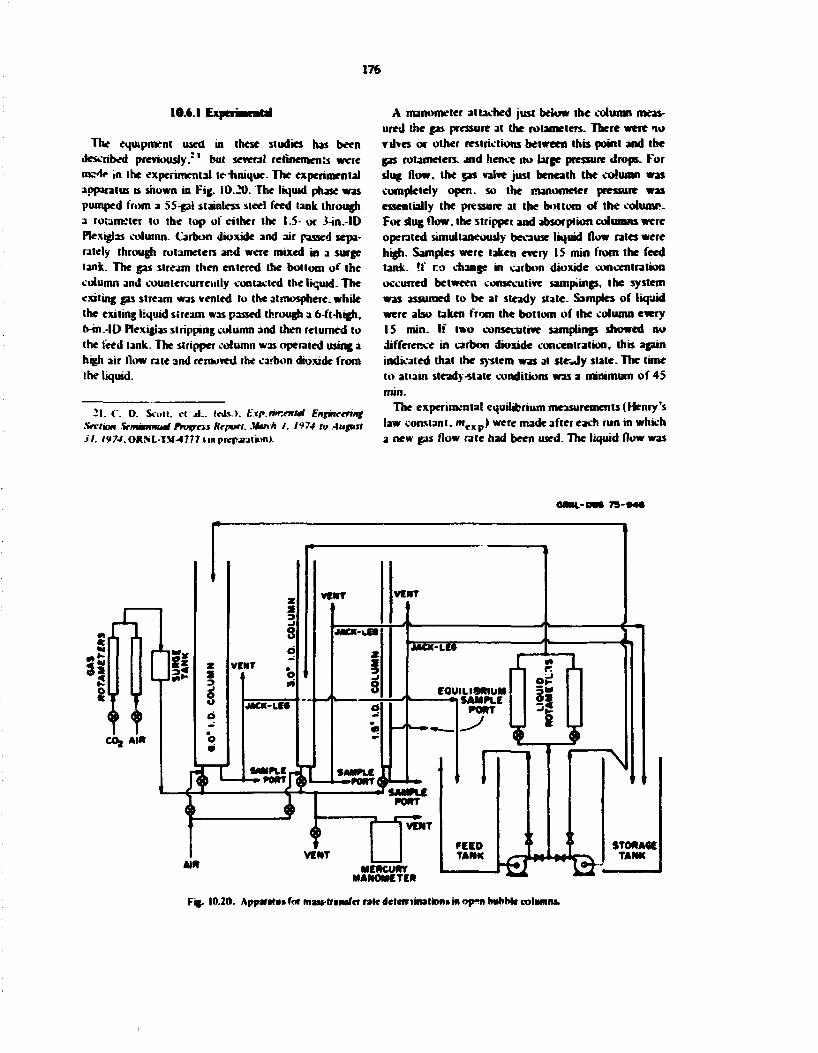
176
10.4.1 Experimental
The equipment used in these studies has been described previously.*1 but several refinements were ms<t<» in the experimental te-iinique. The experimental apparatus is shown in Fig. 10.20. The liquid phase was pumped from a 55-gal stainless steel feed tank through a rotameter to the top of either the 1.5- or 3-in.-ID Plexiglas column. Carbon dioxide and air passed separately through rotameters and were mixed in a surge tank. The gas stream then entered the bottom of the column and countercurreiitly contacted the liquid. The exiting gas stream was vented to the atmosphere, while the exiting liquid stream was passed through a 6-ft-high, o-m.-ID Plexigias stripping column and then returned to the feed tank. The stripper column was operated using a high air (low rate and removed the carbon dioxide from the liquid.
21. t*. D. Scott, ci at.. («LO. Experimental Engineering Section Semiannual Progress Report. Utr\fi I. 1974 to August SI. 1974. ORN'L-TM-4777 tin prepjultunl
A manometer attached just below the column measured the gas pressure at the rotameters. There were no rtfves or other restrictions between this point and the gas rotameters, and hence no large pressure drops. For slug flow, the gas valve just beneath the column was completely open, so the manometer pressure was essentially the pressure at the bottom of the column-For slug flow, the stripper and absorption columns were operated simultaneously because liquid flow rates were high. Samples were taken every IS min from the feed tank. !f no change in carbon dioxide concentration occurred between consecutive samplings, the system was assumed to be at steady slate. Samples of liquid were also taken from the bottom of I he column every IS min. if two consecutive samplings showed no difference in carbon dioxide concentration, this again indicated that the system was at steely state. The time to attain steady-state conditions was a minimum of 45 min.
The experimental equilibrium measurements (Henry's law omstani. mtx ) were made after each run in which a new gas flow rate had been used. The liquid flow was
OMH-OWC 7 3 - M C
MERCURY MANOMETER hd w-
Fig. 10.20. Apparatus for maw-transfer rate dclerrimatiofis in op*» mihMe columns.

177
stopped, and the liquid in the coturvi was allowed to equilibrate with the gas stream. Liquid samples were collected at the 50-cm purl every 15 min until equilibrium was established. Comparison of measured Henry's law constants with literature values 2 2 proved to be a usefui way to check the reliability of earlier data.
Accurate determination of 'Jie carbon dioxide concentration in aqueous samples required considerable care in sampling, in handling samples, and in titration. Three steps were followed carefully to ensure accuracy:
1. Initially 10 ml of 0.01 .V NaOH was emptied into a sample bottle. A steady flow of argon into the sample bottle was applied to create an inert argon blanket above the NaOH. This prevented NaOH absorption of CO; from air. The sample bottle was then covered with a ground-glass cap until the column sample to be tested was prepared.
2. Samples were taken from the tank and column in the following manner: (a) 10-mi samples from the tank were obtained by filling a 10-ml pipet with liquid twice: first to rinse the pipet and then to remove the sample. Care was taken so that no gas bubbles would be drawn into the pipet. (b) Samples from the fcot;om of the column were obtained from the Meed tube located on the jackleg running between the column and the stripper holding tank. Approximately 25 ml of solution was allowed to tlow through the pipet before the sample was collected. No gas bubbles were allowed to be entrapped in the sample, (r) Equilibrium samples were taken from a side port in the same manner described in step 2b.
After the 10-ml sample was collected, it was drained into the sample bottle already containing NaOH. The sampling pipet had been adapted with a No. 10 rubber stopper to provide a snug fit with the sampling bottle, so that air anu additional C 0 2 could be kept out of the sample bottle. Also, the tip of the pipet was below the surface of the NaOH to prevent the argon from stripping C0 2 from the sample solution.
3. The resulting 20 ml of solution (10 ml of NaOH and 10 ml of column sample) was then titrated with 0.01 N HCI to an end point of 8.3 (as recommended by the American Society for Testing and Materials)31
using a Radiometer Copenhagen automatic titrator. During titra'ions. samples were again kept under an argon atmosphere.
22. J. H. Perry, (ed.). Chemical Hnpneers' Handbook. 4ih Ed. McGraw-Hill. New York. 1963.
23. American Society for Testing and Materials. 1912 Annual Book of ASTIH Standards. Pari 23. pp. 34 39. Philadelphia, 1972.
A stoichiometric coefficient based on the weighted equilibrium fraction of H 2 CO } . HCO/. and COj 1 " species present at pH 8.3 is needed to determine the actual total C 0 2 in all samples. Equivalents of base can neutralize C 0 2 in one of two ways:
HjCOj+NaOHriHCOjIiNa^+HjO. (22)
NaHCO, • NaOH ^Na 2 CO, + H 2 0 . (23)
If the reaction stops after the first step, one equivalent of base per mote of C 0 2 is required. But if it continues as in step (2). two equivalents of base per mole of COj are required. The stoichiometric coefficient needed to calculate the true C 0 2 concentration at a final pH of 8.3 can be calculated:
.. _ equivalent base to neutralize C0j 2 ~ *stoic ~
moleC0 2
X (fraction of C0 2 as CO, 2 ")
equivalent ba«e to neutralize HCO/
mole CO,
X (fraction of C0 2 as HCO,")
equivalent base to neutralize H2COj
moleCOj
X (traction of COz as unionized H 2CO,). (24)
The fractions of total CO : present as COj 2 ", HCO.,~. and HJCOJ at pH 8.3 (ref. 5) were found to be 0.0090. 0.9795. aid 0.115 respectively. The A ' M o j c value was calculated as
KiXnK = 2 X 0.009C + 0.9795 X I • 3 X 0.0115
= 0.9975. (25)
Thus, at pH 8.3. essentially all the C 0 2 exists as bicarbonate, which is desirable for limiting absorption or desorption of carbon dioxide. Using the stoichiometric coefficient and the titration data, the concentration of CO] is determined by:
where
Cx - concentration of COj in liquid, g-moles per liter of solution.
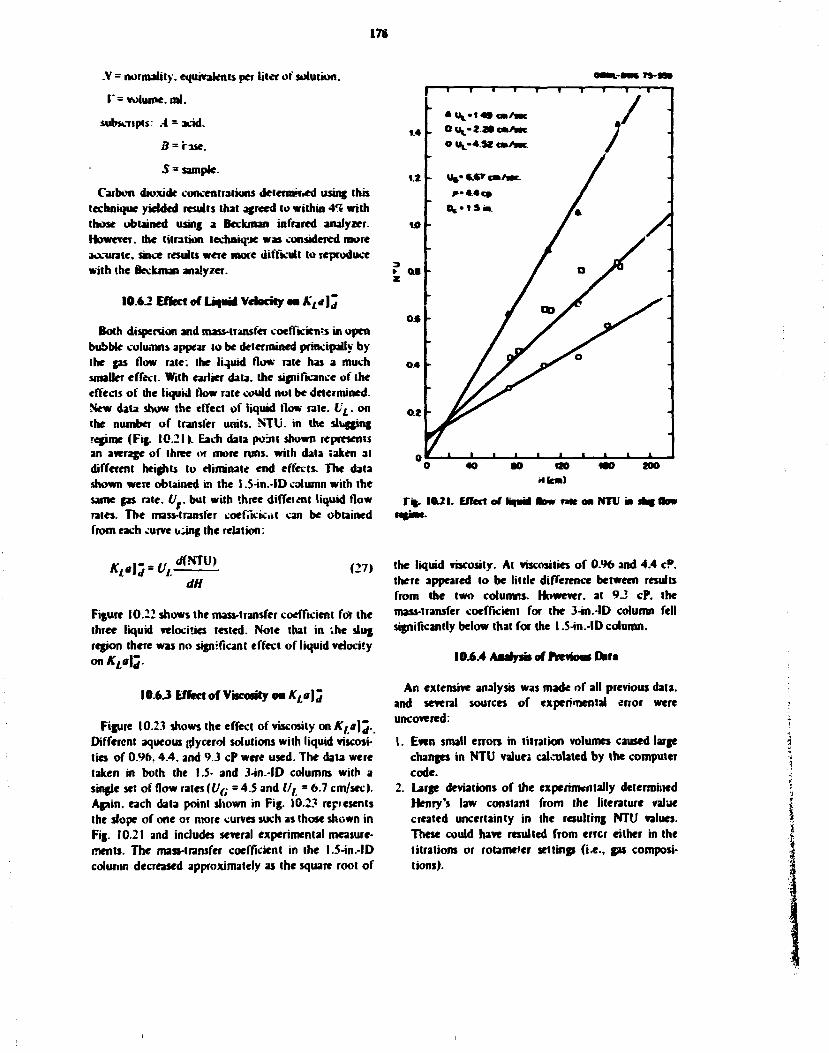
178
.V = normality, equivalents per liter of solution.
I'= volume, ml.
subscripts: A - acid.
3 = rase.
5 = sample.
Carbon dioxide concentrations deternvr.ed using this technique yielded results that agreed to within Al% with those obtained using a Beckman infrared analyzer. However, the titration technique was considered more accurate, since results were more difficult to reproduce with the Beckman analyzer.
10.62 Effect of liquid Velocity on KL*\^
Both dispersion and mass-transfer coefficient in open bubble columns appear to be determined principally by the gas flow rate: the liquid flow rate has a much smaller effect. With earlier data, the significance of the effects of the liquid flow rate could not be determined. New data show the effect of liquid flow rate. LL. on the number of transfer units. NTli. in the slugging regime (Fig. 10.21). Each data point shown represents an average of three or more runs, with data taken at different heights to eliminate end effects. The data shown were obtained in the I .S-in.-ID column with the same gas rale. (/_. but with three diffeient liquid flow rates. The mass-transfer coefficient can be obtained from each curve i^ing the relation:
WU,*™!. (27, dH
Figure 10.22 shows the mass-transfer coefficient for the three liquid velocities tested. Note that in .he slug region there was no significant effect of liquid velocity on KLa)j.
10.6 J Effect of Viscosity on K,a]j
Figure 10.2.1 shows the effect of viscosity on Kta]^. Different aqueous glycerol solutions with liquid viscosities of 0.96.4.4. and ° J cP were used. The data were taken in both the 1.5- and 3-in.-ID columns with a single set of flow rates [VG = 4.5 and Vt - 6.7 cm/sec). Again, each data point shown in Fig. 10.23 represents the slope of one or more curves such as (hose shown in Fig. 10.21 and includes several experimental measurements. The mass-transfer coefficient in the l.5-in.-ID column decreased approximately as the square root of
MM-MNTS-! T 1 I I 1 1 1 1 I I
T%. 1021. Effect of kqaid D n r n t t M NTU in sfcg 1km n%jmt
the liquid viscosity. At viscosities of 0.96 and 4.4 cP. there appeared to be little difference between results from the two columns. However, at 9 J cP. the mass-transfer coefficient for the 3-in.-lD column fell significantly below that for the I .S-in.-ID column.
10.6.4 Andys* of Previons Dart
An extensive analysis was made of all previous data, and several sources of experimental error were uncovered:
1. Even small errors in titration volumes caused large changes in NTU valuei calculated by the computer code.
2. Large deviations of the experimentally determined Henry's law constant from the literature value created uncertainty in the resulting NTU values. These could have resulted from errcr either in the titrations or rotameter settings (i.e., gas compositions).

179
OHML-OWt TS-9M
- 1 1 1 ' 1 - T " 1 /—" 1 1 - 1
O.OM
• •
f OJOK) S
-•
U « - 6 7 c m / s * c -
.J * - 4 4 c » -
OJ0O4 - 1% • 1 5 in. -
« _ _ _ j i~. • « i _ -1 L. _ l _ 1
U L ( C M / S K )
F* . I0J2. Effect of L A <M A , * £ a 4 * ft»
0 .0501 | | | |
f * 0.02O
e * * OJOIO
0 J 0 0 7
0.005
0 0 0 3 I l I 0.6
OftWL-MK 7 5 - 9 4 0 T — I I I I I
• D c * I . S i n .
O 0 C • 1.5 in.
O D c • 3.0 in.
J J I I I I 1 1 2 5
Fg. I0J3. Effector viffo*l)nMA'f«|3-
10

1*0
3. At targe values of F or anal X values, the error associated with computing NTU was large (Fg. 10-24). Some earlier data were not taken near an optimum value for F.
4. Some previous measurements did not allow sufficient : « K to reach steady siate. The time required to attain steady state ia both the column and the feed tank was greater than 45 M M
To select data for correlation, criteria were developed for discarding or retaaiag dab points from previous investigations-1'-1*-1* 2 * These criteria were as follows:
1. Proper F and X values were used, and NTl> did not exceed 3. Hat ensured that the run was carried *-HII at a point where the Mryaudu-Veimtuten* T computational technique was less sensitive to experimental error.
2. Experimental:;/ determined Henry's law constants. mtxf. were consistent with other runs in the same investigation or with literature values. Wher- m<xr
diverged significantly (more than 307) from preceding and succeeding runs or front the available literature value, the point was rejected.
3. Scatter in titration data was not excessive. Usually, the range for titration of our earlier studies was not larger than 025 ml: however, scatter larger than this led to rejeciion of the data.
4. There was a minimum of four points on the NTL' vs //plot (such as Fig. 10.21).
5. Sufficient time was allowed to attain steady stale. Experience showed that the necessary lime was approximately 45 mm: hence, whenever past data indicated that less than M min was allowed lo reach steady stale, the point was discarded.
<i. The scatter of the NTU vs H plot was not excessive. A regression coefficient (concerning the least-squares linear fit. VH j ~- aH * h) of less than 0.9 was indicative of sever. TaMe 10.3 lists all data sets retained.
lvU-5C
14. i. J. T«<tnjfl. *.. Kam-Lmn. J. M. Donahue. and M. Yoncttiwa. Axmri \kxm* in mi Oprn tmhUr Column, •art 17 U»« Trmsfrr f:ff<rls.OKSl.-Mrt-n5 <I97J».
25. A. S. Y. HO. A. I. H-Twary. K. J. Kaplan, and T. L. M-mlfmnety. - IT*** Mtxmx m mi 'fpm Kmhhlr Column. Hrt VII tfcn r#w«/rr A//«f».OItNL-J«'T-l».l«l974>.
X A. Graver. M. I. » M i / . and S. A. Miwlha. Axim"Mixmf in an ftprn Kuhmr Column, fmt VIII Mtss Trrnnftr Effect*. O R M . - M I T I 9 3 H 9 7 4 I .
11. T. Miyaw-hi and T. Vrrmentrn. I vtfiMdmil Diipermm in Snttmt txlrtcwm Cnlummi Mtthrmttirtl Tkenry. I T R L -.Wll Ijwrcnce Radiaimn Uhoralory. Berkeley tAwnni IS.
The volumetric mass-transfer coefficient. A '^)^ . corrected for end effects and dispersion, was correlated with superficial gas velocity, liquid viscosity, and comma diameter. Additional correbtioas were made using dmeasioaless parameters. * £ * I J - expressed in terms of a modified Sherwood number, was correlated with Reynolds number. Schmidt number. Suratn
. and Archimedes i
Re * Reynolds number * t',;P/ tV*»/.
Sc * Schmidt number * « t \pt D,:.
Ar• Archimedes number x j » i r I D r
, / | i / 2 .
Su * Swatman number * Dcplol /JI , * .
Sh = modified Sherwood number * (K,mlDf
ziD,
U, •• superficial gas velocity, cm/sec.
fif * liquid density.g/cc.
cnni-oa* q-Mi
F * . IOJ4. Efreel of t and X on N T l \*
IS!
MuLSmof
T a t Set VL * 6 "L n U 0 , . x10* *>c *V»J
t€t. icwVwc) i*wVm> tcf> «j/cc> l«jracVcn< l e a * / M C I t e a l • • B C ' * »
24 7 3.29 4.17 aw 140 72.75 1.77 JJil © 4 1 1 * S 2JM 4-42 aw IJ00 7Z7S 1.77 341 04215 9 3 3 1 t i l aw 1.00 72.75 1.77 341 04246 I D 2 0 4 2.32 aw 140 72.75 1.77 3Jtl 0 4 0 * 2
25 17-1 4 . IS * J 0 a«; 1 4 0 72.75 1.77 JJtl OJ0290 IS-2 1.91 4.12 IJBO IJOO 72.75 1.77 341 0.0223 19-1 M l 2.11 aw IJOO 72.75 1.77 JJtl 04153 21-2 1.91 3.W aw IJ0O 72.75 1.77 341 04213
2* 1 IJOS I 4 » avi IJOO 7197 1.77 7 4 2 0.0092 * O J J ©49 a 9 i I J » 7197 1.77 742 0 4 0 4 0
19 1 4 4 * 10.45 9 4 2 1.14 7O00 0.1*3 341 04123 a 4 .5 * *-71 9 4 * 1 14 70JOO 0 1 * 3 341 04011 in 0 J 2 OJJ 9.20 1 14 7000 0.1*3 341 0 4 0 1 0 V 4_S4> *-77 4 .4* 111 70.40 0.341 341 ©4123 V I 4 3 * 10.24 4.40 1.11 7 a 4 0 0.341 311 C 4 I I 2 V H i U 2 ©45 4.40 1.11 70.40 0.341 341 04017 V M 0 J 2 CX5* 4.40 I I I 70.40 0.341 :-4l 04017
27 1 4.52 • 4 0 4.40 M l TO.40 0 3 4 1 341 0.012* ni 1.49 • .70 4.30 M l 70.40 0.341 341 04121 IV 0.41 OJJ O.W IJbO 72.75 1.77 341 0 4 0 * 4
vn 4 .5 * *-70 a 9 5 IJOO 72.75 1.77 341 04235 VIM 3.29 4.10 a9S IJOO 72.75 1.77 341 04137 IX 244 2.40 0.95 IJOO 72.75 1.77 341 0.0070 X ' .25 • 4 0 aw IJOO 72.75 1.77 742 0 4 2 2 * X I I 1.25 * 4 0 4 4 0 1.11 70.40 0.341 742 0 4 1 4 * X I U 1.25 * 4 0 9.70 1.14 7O.00 0.1*3 742 04047
u( » column diameter, cm.
1*1 = liquid viscosity. cP.
Du~ diffusrvity. cm1 /sec.
g * gravitational comtanl * 9R0 cm/sec1.
O/ * surface tension, dynes/cm.
KLi * volumetrr- mas*-transfer coefTicieni. sec"'.
To facilitaic the correlations, a computer code was written lo calculate the dimcnsionlcss groups and lo interface with an IBM Scientific Subroutine Package for •nuliiple linear regression. The criteria for evaluating the quality of each correlation were
1. the multiple correlation coefficieni. which represents the fraction of the total variance explained by the regression coefficients.
2. the i statistic for each independent variable, which indicates each independent variable's relative value in the correlation, and
3. the F statistic, which it indicative of the overall degree of confidence in the correlation.
Only legiessions with a correlation coefficient greater than 0.9 were considered- Correlation with the -~olumn diameter in any combination was low in power dei. end-enc* (absolute value less than 0.2) and of low significance. Although this is in disagreement with earlier findings.15 only five sets of data in the larger diameter column were used in the correlations- The best correlation in terms of both correlation coefficient and F statistic was:
K,,\ l*U I2*»
« 0*0490 U G
0 J M 3 t 0 , 2 4
B | _ 0517±0.120
with the Wr confidence intervals of the exponent. Figure 10.25 shows the correlation and al of the reliable data.
Correlation of the modified Sherwood number with Reynolds. Schmidt, and Suraiman numbers abo yielded high correlation coefficients and F statistics. Their correlation was:
S h * I . I I X I 0 - " R e 0 J 4 9 ± 0 1 - 6
S..IJI ±0.41 ^1.15 ±0.42 i y t )

1*2
»-*«»
FifM* IC-26 presents a plof of Eq. ( » for aH ike icbbie data. Equation (29) was chose* over those involving the Archimedes number for three reasons:
1. Eqoalwa(29)wassutBtkaly better. 2. The Suratman number B more applicable to dog
flow, as evidenced by the feci that rVcfet numbii has been correlated with Suratuan number in the slug regime and with Archimedes number in the babble regime and most of the poinls corresponded to slug flow.1*
3. The Sumnon number introdaces a new variable. 9f. Although Of does not vary greatly throughout the study, the correlation mdicaies that 9L is * significant variable. Future studies which investigate varying surface tension w»l check this poini-
101*
1. The titration technique used was shown to be both accurate and precise.
2. In the dug-flow regime, liquid-flow rale has a ncghpok effect on liquid-fini mass-transfer coeffi-cienis. ^ / « | } -
J». D. F.. Fcrt**m. « at. feu*.). Chemtcwi Tukmutot? O M H N Ammtl Propm Report. Aft* I. 1972 to Jfer* Jl. /•7J.OvWL<4M3.
V The two best correlations for liquid-film mass-transfer coefficients (determined by evatuatrjn of / statistics. F statistics, and the overal correbtion coefficient) were:
A ^ - O J O O W U , ; * * * 3 * * 1 * m 051710.120 (30)
a- i . i ix io -" i to* M , t a - l i -s j * * ) ±0410^1 15 ±042 ( 3 | >
10.7 CONTOTUAL DESIGN OF FUEL
J.R.rhghtower.Jr.
design is being prepared for a Si 2 MSB* Fuel Processing Engineering Center. The [wnl provide space for the engineering devdop-
•i of furi processing t< A floor plan for the Fuel
Center (FPEC) buidmg has been developed, reviewed and accepted. The three-story
i s - * * * I I I M i l l I I I I I f i l l
' • • • • • • • • • * • * ' • "
i.if.tr^mTW'wr Fv> MM. Vt*t of KiynsnJs,

1S3
office space for ibout 40 people, a high bay area for large experiment, laboratories, equipment storage areas, change facilities, a lunch room, and a conference room. The building will be approximately ISO ft wide X 175 ft long X SO ft h%h. with a rngh bay area which will be 81 ft wide X 128 ft long X 45 ft high-
The high bay and laboratories will be suitably ventilated to bouse beryllium and thorium fluorides. Space has been provided for a facility to prepare and
pvify molten salt mixtures needed in the MStR program-
The design discipline effort necessary to rumpfctr die FFEC conceptual design has been started. The Engineering Job nan which has been developed cals for a prelimimry schedule 44 construction project data sheet to be submitted by Apri 15: a final iirhrlnlr 44 to be submitted by June 30: and die conceptual design report to be issued and approved by September.
Pan 5. Salt Production
IL ProdWtkm of Flaondc Sale Mamies for Research aad DerclopacM
A n i l nrodatiioa facasty is operated for preparation of a h saixiaves leoaned by cimeraneaters M the HSR lYognmt- 7*r cossaoarra of the anxtams ami die
parity. Major objectivrs daring das reponast, period wnc
qmtiaaed prodacrioa of a l l m the imal rrd< research faciHy. aad maadetwa aad start-ap of the larger-scale prodartioa faciay. The fir* mjectrve was attaastd •idioal major deny 10 dse program, mi the second was any cfwe to scheame with loaning of die first hatch of ok started oa Febraary 2*. I*»75.
Auiiwiri daring dse report period fal m dace catenaries: (11 sal* prodaciwa. «2» tacatty and eamo-anM ntoddscatioa. and (3) peripheral aiiivnstj dui iadade awaauiiua of safe-transfer vessels, assistance to others m emaament deaa-ap. and reactivation of EaaTflaTar'WMC lavmavvnmvaTZ la?nClanP$ln5S 3 H O 0 V O C 0 f l a W 6 S .
Safe: aos pro dated ooatiaaoasly daring das period except for snterrwptioes for aaatyscs aad for transfers iato other vessels- Total prodartioa of salt was 35S kg m date diffcreat cianauaiina* This mzterai was dthvered m 22 dirwaeat containers, repairing a total of 30 safe iraasfcrs. hi a* cases the vessels used acre part sealed aHfe hydrogen at ttmpt.iiarei XrfO°C to M V a f C C flla^tMavC OSUSCS-
Most of the safe 1350 kg) was predated m die S-m.-dana reactor. Tea hatches (35-fcg eachl acre processed for IS hr each widi HF-H, aad for 30 hr with Hj ak«e (avenge times). The average HF coaieat of the offgas was wanted from 0.4S aseg per User of ofT-gat at i hr of Hi strtppjaf to 002 org per Met nf off-gas at 30 hr. At dris poiai. the ledactawi rale was changing sc sfowfy dial die procrmag was icrmavmd. These nines are based oa titration of Isf w die off-gas stream wish KON wuaj pMcaolanduIrm mdsesior. The gas vohawf which has been stripped of HF » detcr-maicd by pesaag die gas throws* a dantaccment
<wet-test) gas saner. The astdmd does aot provide NgUy prccue vataes bat by uhsuiiag dse Head of a saaade lories the cad poatts for HF-llj n*_ nemt ami for H. irdmtiua cat be ntaimd- The sak sssassakd at the end of rise ra» by aaeroag a copper sample cap •MO dsc asth thinajh aa argua paiged saaafaagdevice; tar saaarang rod aad cap wbkh coatacts rise salt are hydrogen-feed to etaamatc oiides before samphng. Aaatytical it—It* or. die sail made fc- Lie show iraa at I JO pan. chtuaaaa) at •=• pps*. asckel at 3S ppm. sattar at 6 ppai aid oxygen at 112 earn. These are averaacs tor a l saaades. aad wobJbh die vahsts aw o v v s a g > # »^#* aasn «vvswajp^a* ^ nnwj a* a a pvjpnnapwy oww* WVSVS^^^W M W
KuaMWy ttpvutmutfc except Urn oxyfta. Dme %o • i |, a^psBaaa^aaak ^mA\ «^saaak|p> ^^sSjiTgaaaa) fafMaTgs BBaaE' saajgasaa/ 4 - f
the oxygea resales are fcxfh. The buhanur of diese satis •a conosioa loop txptraataii leads to verify das last statesKeai.
The £wdity aad eoaspaseai-piepara««w effort has beea coaceracd asaaty wvdi die targe prodactna facasty. Aaew 12-a -dsaa prnnf iiaa, reactor aad a aew adsdowa vessel which were dnaard aad fabricated to
esjstiaf faraaces M the prodaclioa facday. The dec-trical power system was ••grated to provide separate coniaclors for dse famace upriitmg coatrob aad for the ha> trmprij»aie safety cat-off. A l mtuisv parts of dse eojsapmeai were groaaded aad aew aaxassry liar hcatatg cncaMs wish Vasssc control were mstaled. AH pspasg was ddier renewed or iasperted aad ctraaed. The cbarpmg system for ioaamg die coaspoacat aMe-rids ssto the aaisdowa veaed was rebadt for mure posswve flow of solids auv the vessel. AH control aad alarm caewts were cheched md naasrd circaiu aad eojaipmcMt were nmoved. A aew hydrogen-control system was msialed for protection apiasi loss of hydrogen pressarc or loss of electrical power.
The peripheul fMictions mctadrd demmg and fabrs-jaiiaa of salt coalajnrrs to be need for delivery
ltd

its
pwpum A variety of vends b ace«M to aaeet the •eeos of expenaaraiers. mi a l avast be of saitaMe •Merofe (copper or iMafc'-atcfccI aloys) aaaf •ant be
of a healed «at (locate*' a* a special baaing) for
faoaa dac *at aae akauei BHO aa opea ctacrete pit •Jbjete ahcv arc bcM UaaaoraraV Wbm a flaffitacait
lirr|Mi—i aa4 Ihnii— > is paaapea1 iato a laafc ualer aarf takes aany far •upmal A l20Ofal stcd taak locairal m M * * « » l - 3 «nkh serves as a botfcag task for JOMUMK froai floor waaas a*4 sjaks m * e rait aeoaaKtio* area was leafcaafarai are rraaare*.
Work at the prcscaiaoi « the iaaaaeosMe fawor* • * be cDaccMMN oa proaWiioa) of sah banag oW n- jn i imi 7 M * - I 2 aaafe % UF- f t r fV IV* M H K
tanjt proaajcoM racafey f 155 kg per batda

4
UB
MOITEN-SAIT REACTOt PtO AUGUST 197S
L (
X * . M E ifccOY*"
J RtfcSTEFANO* O.ACAVM*
'HART TIME OR) "OUAL CAPACITY
•"COOP
AC ANALYTICAL CMEIlBETRV 01 V«IOPI C CMEMMTRV CMWOM
CT CHIMICAlTCCHMOlOGVOlVJSlON UK MtTAlSAHOCEIMMGiOIVlSMN
R REACTOR 01 VWOft UT (JMVf N*TY OF TENNCSME
CE.OUNN* ». H FARMER* J. C FELTMCR XLCR-FnTH* L HEATHERLY* J. W.I T.XI JO E.J. I G A POTTER I G RAROON* M M ! LAS C K.THOMAS* L R. TROTTER* C A.WALLACE* J. J.'
X I
I

BLANK PAGE
l !

L
CTOtPtOGtAM
i
jBUMOMfCTM
I
• — •
CT
* C c
H T
CT CT CT cr CT CT CT CT CT
M L T f M K J C r a
a « L N O « T a i CT r LOMir CT
mxtmrtm CT «.L.nniiM CT
— 1 ! • • ! ! • 1 m m w c
A o n i K i s c L M A T A c ft f MITCH* c S. CANTO** c t - « - T O T H * c U O G a M T I H C K - c n w w c H ft.-MGHSTIfM c
a t N E A T H L A L Y c D. Y. V A U N T M t c
AMALYTtCAl CMBBt l
mnumcMtmooevtammmT A 1 MteYEft* AC
U F A f K I ' AC • ft CLANK* AC J M. DALE* AC D. L- MANVHPIG AC J. P. YOUNG* AC
ANALYSES
L T OOftftN* AC J H OOOFEtt* AC *». ft LAlNC* AC J. A CAMTEn* AC
COWMILTMT
C MANANTOV* ITT
e