socket boards for evaluating 1-wire devices evaluates ds9120
TRANSCRIPT
Socket Boards for Evaluating 1-Wire DevicesEvaluates: DS9120
For pricing, delivery, and ordering information, please contact Maxim Direct at 1-888-629-4642, or visit Maxim Integrated’s website at www.maximintegrated.com.
General Description
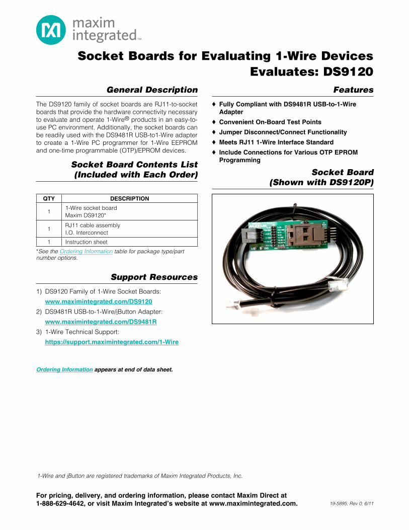
The DS9120 family of socket boards are RJ11-to-socket boards that provide the hardware connectivity necessary to evaluate and operate 1-WireM products in an easy-to-use PC environment. Additionally, the socket boards can be readily used with the DS9481R USB-to1-Wire adapter to create a 1-Wire PC programmer for 1-Wire EEPROM and one-time programmable (OTP)/EPROM devices.
Socket Board Contents List (Included with Each Order)
Support Resources
1) DS9120 Family of 1-Wire Socket Boards:
www.maximintegrated.com/DS9120
2) DS9481R USB-to-1-Wire/iButton Adapter:
www.maximintegrated.com/DS9481R
3) 1-Wire Technical Support:
https://support.maximintegrated.com/1-Wire
Features
S Fully Compliant with DS9481R USB-to-1-Wire Adapter
S Convenient On-Board Test Points
S Jumper Disconnect/Connect Functionality
S Meets RJ11 1-Wire Interface Standard
S Include Connections for Various OTP EPROM Programming
Socket Board (Shown with DS9120P)
1-Wire and iButton are registered trademarks of Maxim Integrated Products, Inc.
19-5895; Rev 0; 6/11
Ordering Information appears at end of data sheet.
*See the Ordering Information table for package type/part number options.
QTY DESCRIPTION
11-Wire socket boardMaxim DS9120*
1RJ11 cable assemblyI.O. Interconnect
1 Instruction sheet
Socket Boards for Evaluating 1-Wire DevicesEvaluates: DS9120
2Maxim Integrated
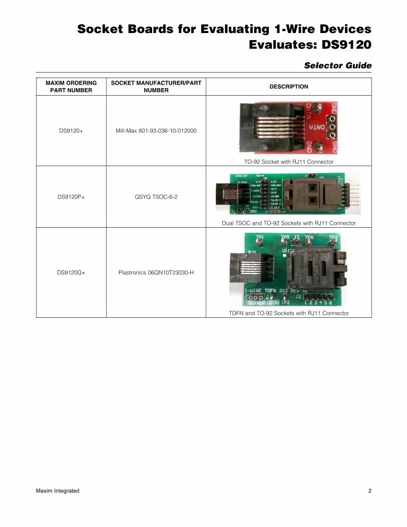
Selector Guide
MAXIM ORDERING PART NUMBER
SOCKET MANUFACTURER/PART NUMBER
DESCRIPTION
DS9120+ Mill-Max 801-93-036-10-012000
TO-92 Socket with RJ11 Connector
DS9120P+ QSYQ TSOC-6-2
Dual TSOC and TO-92 Sockets with RJ11 Connector
DS9120Q+ Plastronics 06QN10T23030-H
TDFN and TO-92 Sockets with RJ11 Connector
Socket Boards for Evaluating 1-Wire DevicesEvaluates: DS9120
3Maxim Integrated
Detailed Description of Hardware
1-Wire Socket BoardsThe DS9120 family of 1-Wire socket boards are 1-Wire accessories that support 1-Wire EEPROM, EPROM, and ROM devices for different packages. See the Ordering Information table to determine which socket board is available for each package type. All socket boards include the socket and RJ11 cable assembly (see the Socket Board Contents List (Included with Each Order)) table for the complete list).
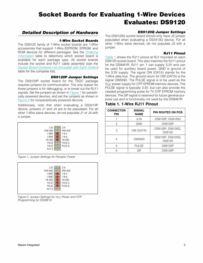
DS9120P Jumper SettingsThe DS9120P socket board for the TSOC package requires jumpers for communication. The only reason for these jumpers is for debugging, or to break out the RJ11 signals. Set the jumpers as shown in Figure 1 for parasiti-cally powered devices, and set the jumpers as shown in Figure 2 for nonparasitically powered devices.
Additionally, note that when evaluating a DS2413P device, jumpers J1 and J4 are to be populated. For all other 1-Wire slave devices, do not populate J1 or J4 with a jumper.
DS9120Q Jumper SettingsThe DS9120Q socket board should only have J3 jumper populated when evaluating a DS2413Q device. For all other 1-Wire slave devices, do not populate J3 with a jumper.
RJ11 PinoutTable 1 shows the RJ11 pinout at RJ1 mounted on each DS9120 socket board. This also matches the RJ11 pinout for the DS9481R. RJ11 pin 1 can supply 3.3V and can be used for auxiliary board power. GND is ground of the 3.3V supply. The signal OW (DATA) stands for the 1-Wire data bus. The ground return for OW (DATA) is the signal OWGND. The PULSE signal is to be used as the VCC power supply for OTP EPROM memory devices. The PULSE signal is typically 3.3V, but can also provide the needed programming pulse for 7V OTP EPROM memory devices. The GP signal is reserved for future general-pur-pose use and is functionally not used by the DS9481R.
Figure 1. Jumper Settings for Parasitic Power
Figure 2. Jumper Settings for VCC Power and OTP Programming for DS28E10
Table 1. 1-Wire RJ11 Pinout
CONNECTORPIN
SIGNALNAME
PIN ROUTED ON PCB
1 3.3V DS9120P, DS9120Q
2 GND DS9120P
3 OW (DATA)DS9120P, DS9120Q,
DS9120
4 OWGNDDS9120P, DS9120Q,
DS9120
5 PULSE DS9120P
6 GP DS9120P
3.3VRAW-GND
1-WIRE1-WIRE
1W-GNDPULSEPULSERJ11-6
3.3VRAW-GND 1-W-A 1-W-B 1W-GND PULSE-A PULSE-B
3.3VRAW-GND
1-WIRE1-WIRE
1W-GNDPULSEPULSERJ11-6
3.3VRAW-GND 1-W-A 1-W-B 1W-GND PULSE-A PULSE-B

Socket Boards for Evaluating 1-Wire DevicesEvaluates: DS9120
4Maxim Integrated
DS9120 Family of Socket Board Schematics and Layout
Figure 3. DS9120+ Socket Board Schematic
Figure 4. DS9120+ Socket Board Composite Layout
Socket Boards for Evaluating 1-Wire DevicesEvaluates: DS9120
5Maxim Integrated
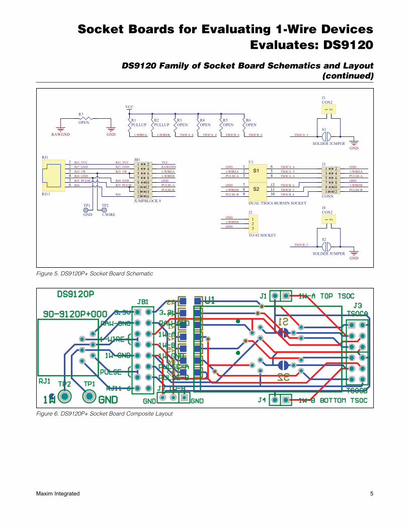
DS9120 Family of Socket Board Schematics and Layout (continued)
Figure 5. DS9120P+ Socket Board Schematic
Figure 6. DS9120P+ Socket Board Composite Layout
Socket Boards for Evaluating 1-Wire DevicesEvaluates: DS9120
6Maxim Integrated
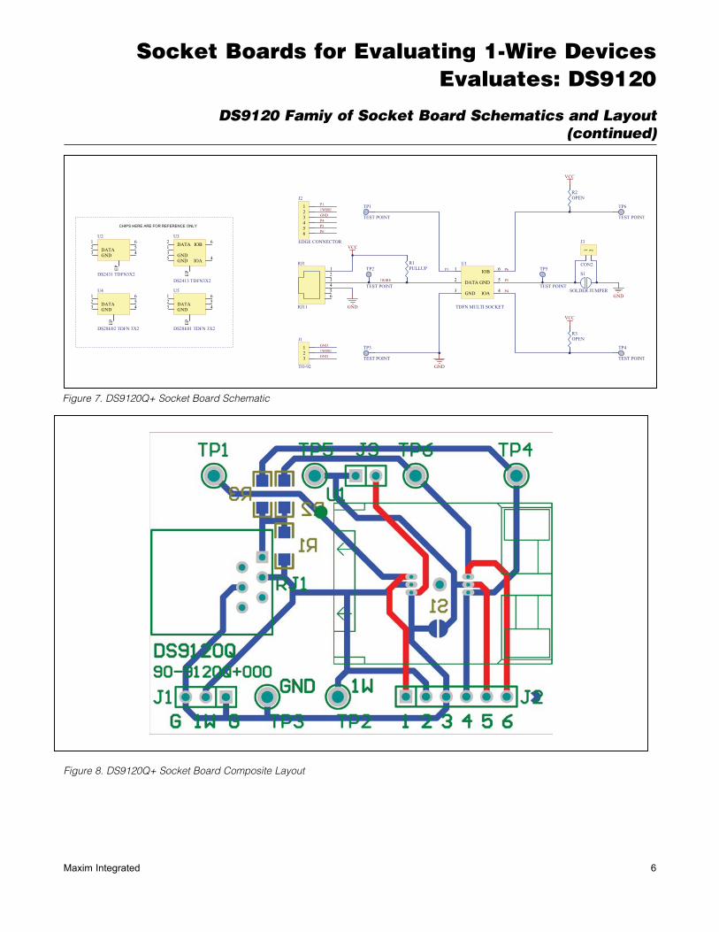
DS9120 Famiy of Socket Board Schematics and Layout (continued)
Figure 7. DS9120Q+ Socket Board Schematic
Figure 8. DS9120Q+ Socket Board Composite Layout
Socket Boards for Evaluating 1-Wire DevicesEvaluates: DS9120
7Maxim Integrated
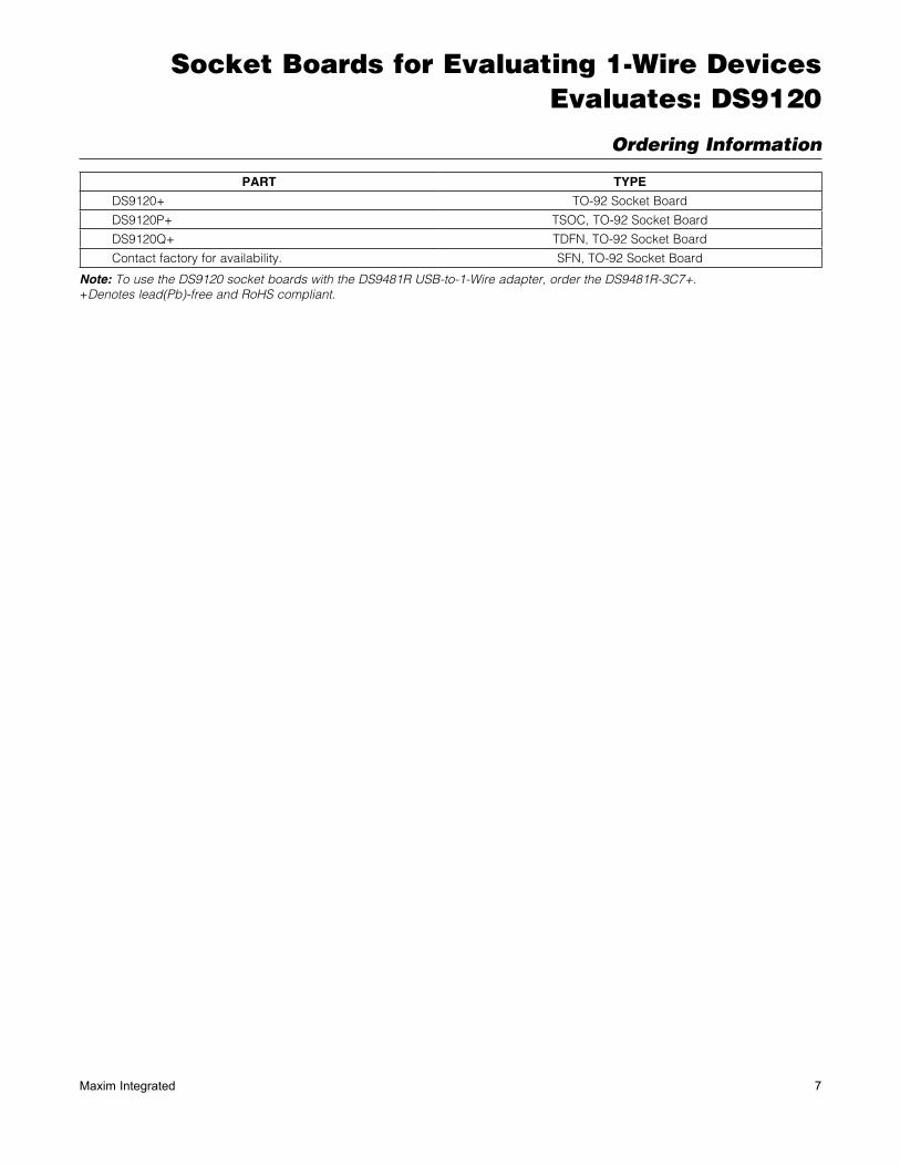
Ordering Information
Note: To use the DS9120 socket boards with the DS9481R USB-to-1-Wire adapter, order the DS9481R-3C7+.+Denotes lead(Pb)-free and RoHS compliant.
PART TYPE
DS9120+ TO-92 Socket Board
DS9120P+ TSOC, TO-92 Socket Board
DS9120Q+ TDFN, TO-92 Socket Board
Contact factory for availability. SFN, TO-92 Socket Board
Socket Boards for Evaluating 1-Wire DevicesEvaluates: DS9120
Maxim Integrated cannot assume responsibility for use of any circuitry other than circuitry entirely embodied in a Maxim Integrated product. No circuit patent licenses are implied. Maxim Integrated reserves the right to change the circuitry and specifications without notice at any time.
Maxim Integrated 160 Rio Robles, San Jose, CA 95134 USA 1-408-601-1000 8© 2011 Maxim Integrated Products, Inc. Maxim Integrated and the Maxim Integrated logo are trademarks of Maxim Integrated Products, Inc.
Revision History
REVISIONNUMBER
REVISIONDATE
DESCRIPTIONPAGES
CHANGED
0 6/11 Initial release —