soda { a multimode vhf/uhf software de ned radio · 2019-01-23 · soda { a multimode vhf/uhf...
TRANSCRIPT
SoDa – A Multimode VHF/UHF Software
Defined Radio
Matthew Reilly (kb1vc)
April 14, 2014
Abstract
SoDa is a software defined radio system using the Ettus Radio USRPand its WBX VHF/UHF daughtercard. SoDa implements an all-mode(CW, USB, LSB, AM, NBFM, WBFM) radio suitable for use as anexciter/IF-strip for microwave transverters and in the VHF and UHFham bands.1
1 Introduction
In 2012 I began work on an IF radio to drive a 10GHz transverter system. Theprevious radio – an FT817 – had worked well, but it was time for a change. Thisprovided an excuse to try out the USRP/N200 software defined radio systemmanufactured by Ettus Research. It was also the impetus to develop SoDa, thesoftware defined radio application for the N200.
The goals of the SoDa project were modest:
• Function as a “learning lab” to explore software defined radio and digitalsignal processing concepts.
• Provide a practical platform for interfacing to a microwave transverter.
• Create a versatile all-mode exciter for the VHF and UHF amateur bands.
• Improve on the performance of my earlier microwave systems that usedan “analog” IF radio.
Of the four goals, the first was the actual motivation. As a result, all com-ponents in the signal processing chain for the SoDa radio are developed “fromscratch” though there are numerous toolkits and signal processing libraries that
1This article was first published in the proceedings of “The 40th Eastern VHF/UHF Con-ference” on April 11-13, 2014.
1
might have served the other goals. For instance, GNU Radio[1] offers manyuseful building blocks for construction of a transceiver, but I really wanted theexperience of developing all the components – filters, mixers, oscillators, andthe rest.
1.1 The USRP Hardware
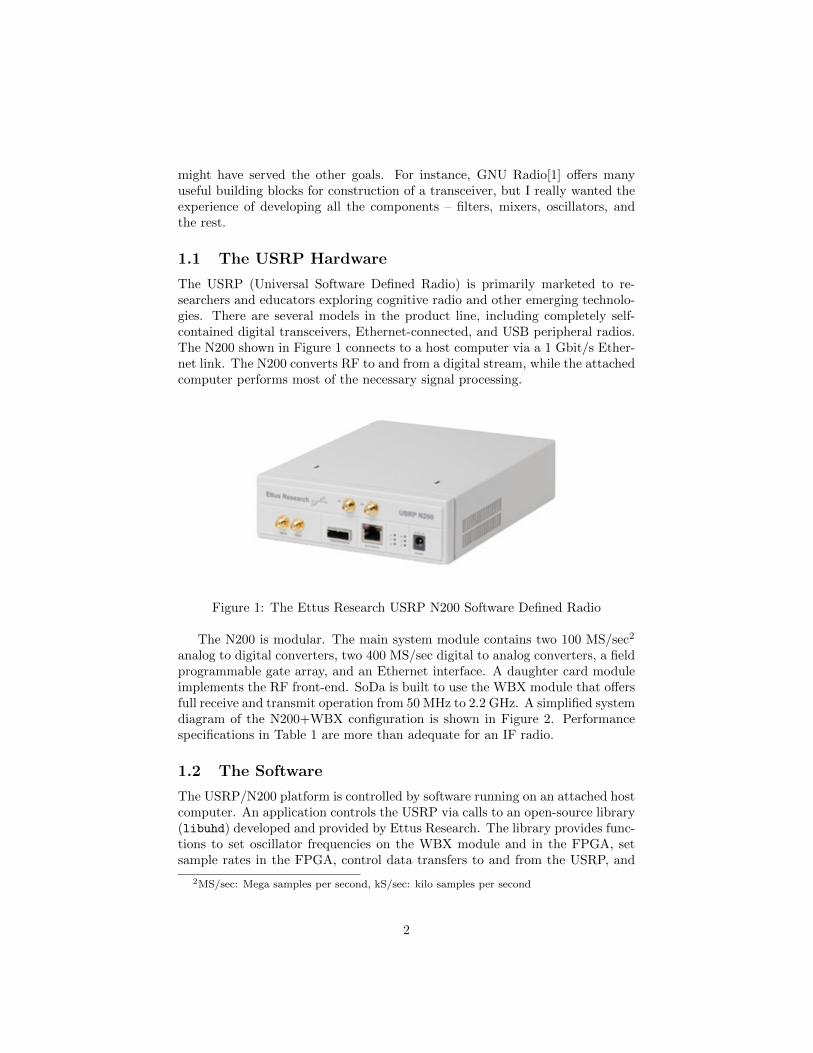
The USRP (Universal Software Defined Radio) is primarily marketed to re-searchers and educators exploring cognitive radio and other emerging technolo-gies. There are several models in the product line, including completely self-contained digital transceivers, Ethernet-connected, and USB peripheral radios.The N200 shown in Figure 1 connects to a host computer via a 1 Gbit/s Ether-net link. The N200 converts RF to and from a digital stream, while the attachedcomputer performs most of the necessary signal processing.
Figure 1: The Ettus Research USRP N200 Software Defined Radio
The N200 is modular. The main system module contains two 100 MS/sec2
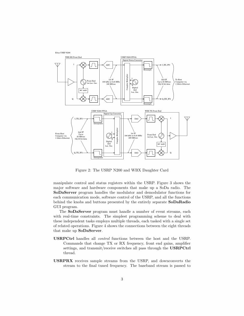
analog to digital converters, two 400 MS/sec digital to analog converters, a fieldprogrammable gate array, and an Ethernet interface. A daughter card moduleimplements the RF front-end. SoDa is built to use the WBX module that offersfull receive and transmit operation from 50 MHz to 2.2 GHz. A simplified systemdiagram of the N200+WBX configuration is shown in Figure 2. Performancespecifications in Table 1 are more than adequate for an IF radio.
1.2 The Software
The USRP/N200 platform is controlled by software running on an attached hostcomputer. An application controls the USRP via calls to an open-source library(libuhd) developed and provided by Ettus Research. The library provides func-tions to set oscillator frequencies on the WBX module and in the FPGA, setsample rates in the FPGA, control data transfers to and from the USRP, and
2MS/sec: Mega samples per second, kS/sec: kilo samples per second
2
ADC
Resample
Resample
1st IF100 kHz to 6.25 MHz
100 MS/sec
2nd IFUp to 25 MS/secI/Q 16 bit data
ADCQ
I
90° shift
WBX RX Front End USRP N200 FPGA
Front End1st Loc. Osc.
Digital2nd
Loc. Osc.
I_RX_IF2
Q_RX_IF2
Ettus USRP N200
DAC
1st IF100 kHz to 6.25 MHz
200 MS/sec
DAC Q
I
90° shift
WBX TX Front End USRP N200 FPGA
Front End1st Loc. Osc.
Digital2nd
Loc. Osc.
To Host Computer via1 Gbit/s Ethernet
Interpolate
Interpolate
I_TX_IF2
Q_TX_IF2
2nd IFUp to
25 MS/secI/Q 16 bit data
From Host Computer via1 Gbit/s Ethernet
Com
plex
Mul
tipl
ier
I
Q
Com
plex
Mul
tipl
ier
I
Q
Digital Down-Converter
Digital Up-Converter
Figure 2: The USRP N200 and WBX Daughter Card
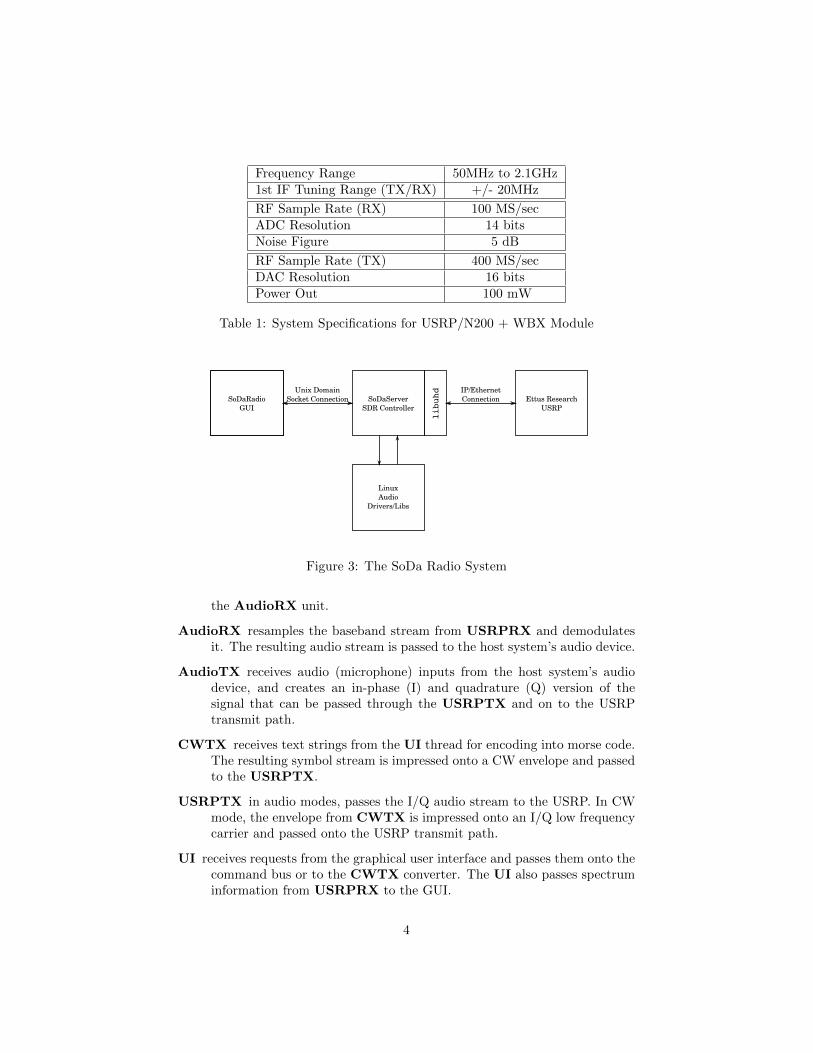
manipulate control and status registers within the USRP. Figure 3 shows themajor software and hardware components that make up a SoDa radio. TheSoDaServer program handles the modulator and demodulator functions foreach communication mode, software control of the USRP, and all the functionsbehind the knobs and buttons presented by the entirely separate SoDaRadioGUI program.
The SoDaServer program must handle a number of event streams, eachwith real-time constraints. The simplest programming scheme to deal withthese independent tasks employs multiple threads, each tasked with a single setof related operations. Figure 4 shows the connections between the eight threadsthat make up SoDaServer.
USRPCtrl handles all control functions between the host and the USRP.Commands that change TX or RX frequency, front end gains, amplifiersettings, and transmit/receive switches all pass through the USRPCtrlthread.
USRPRX receives sample streams from the USRP, and downconverts thestream to the final tuned frequency. The baseband stream is passed to
3
Frequency Range 50MHz to 2.1GHz1st IF Tuning Range (TX/RX) +/- 20MHz
RF Sample Rate (RX) 100 MS/secADC Resolution 14 bitsNoise Figure 5 dB
RF Sample Rate (TX) 400 MS/secDAC Resolution 16 bitsPower Out 100 mW
Table 1: System Specifications for USRP/N200 + WBX Module
SoDaRadioGUI
SoDaServerSDR Controller
LinuxAudio
Drivers/Libs
Ettus ResearchUSRP
IP/EthernetConnection
Unix DomainSocket Connection
libuhd
Figure 3: The SoDa Radio System
the AudioRX unit.
AudioRX resamples the baseband stream from USRPRX and demodulatesit. The resulting audio stream is passed to the host system’s audio device.
AudioTX receives audio (microphone) inputs from the host system’s audiodevice, and creates an in-phase (I) and quadrature (Q) version of thesignal that can be passed through the USRPTX and on to the USRPtransmit path.
CWTX receives text strings from the UI thread for encoding into morse code.The resulting symbol stream is impressed onto a CW envelope and passedto the USRPTX.
USRPTX in audio modes, passes the I/Q audio stream to the USRP. In CWmode, the envelope from CWTX is impressed onto an I/Q low frequencycarrier and passed onto the USRP transmit path.
UI receives requests from the graphical user interface and passes them onto thecommand bus or to the CWTX converter. The UI also passes spectruminformation from USRPRX to the GUI.
4
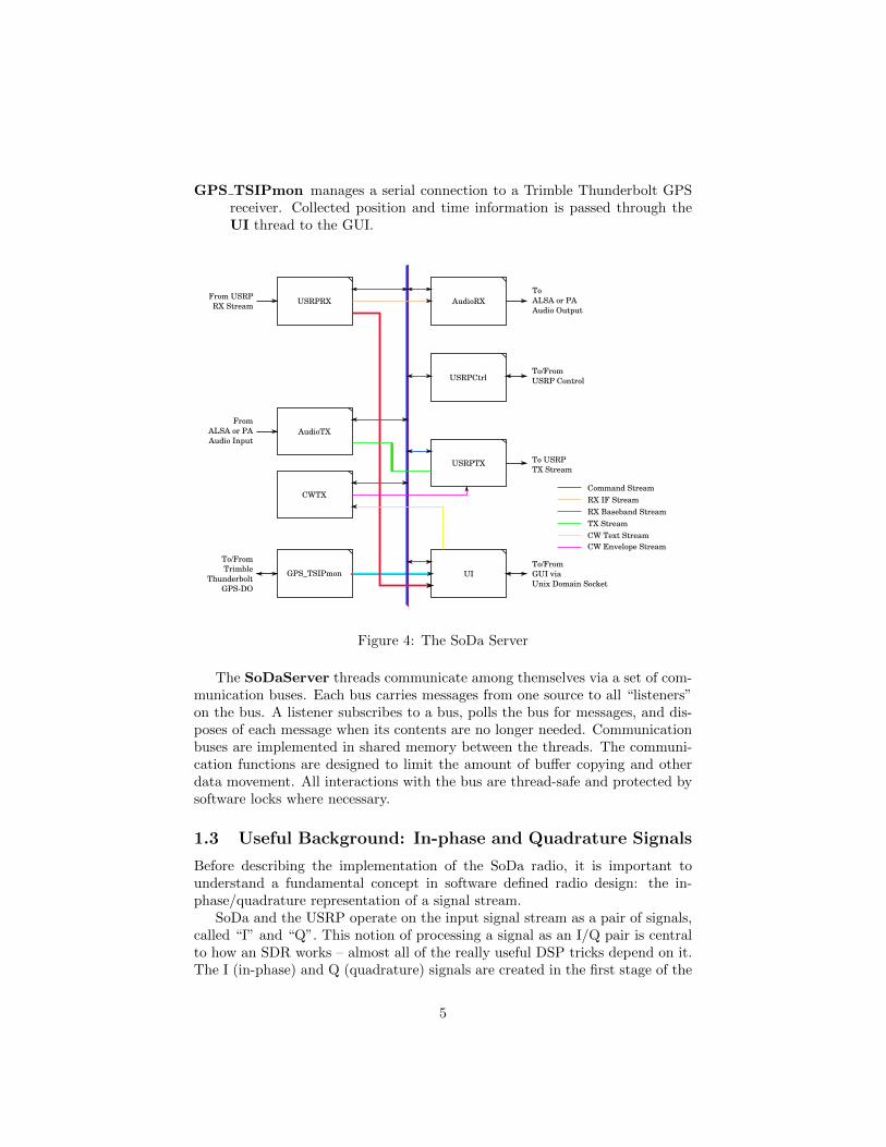
GPS TSIPmon manages a serial connection to a Trimble Thunderbolt GPSreceiver. Collected position and time information is passed through theUI thread to the GUI.
USRPRX AudioRX
AudioTX
CWTX
USRPTX
USRPCtrl
UIGPS_TSIPmon
From ALSA or PA Audio Input
To ALSA or PAAudio Output
To/FromUSRP Control
To USRP TX Stream
From USRPRX Stream
Command Stream
RX Baseband StreamTX StreamCW Text StreamCW Envelope Stream
RX IF Stream
To/FromGUI viaUnix Domain Socket
To/FromTrimble
ThunderboltGPS-DO
Figure 4: The SoDa Server
The SoDaServer threads communicate among themselves via a set of com-munication buses. Each bus carries messages from one source to all “listeners”on the bus. A listener subscribes to a bus, polls the bus for messages, and dis-poses of each message when its contents are no longer needed. Communicationbuses are implemented in shared memory between the threads. The communi-cation functions are designed to limit the amount of buffer copying and otherdata movement. All interactions with the bus are thread-safe and protected bysoftware locks where necessary.
1.3 Useful Background: In-phase and Quadrature Signals
Before describing the implementation of the SoDa radio, it is important tounderstand a fundamental concept in software defined radio design: the in-phase/quadrature representation of a signal stream.
SoDa and the USRP operate on the input signal stream as a pair of signals,called “I” and “Q”. This notion of processing a signal as an I/Q pair is centralto how an SDR works – almost all of the really useful DSP tricks depend on it.The I (in-phase) and Q (quadrature) signals are created in the first stage of the
5
USRP receiver hardware when the single channel from the antenna is multipliedby the local oscillator output (to generate the I channel) and a replica of theLO output shifted in phase by 90◦ (to generate the Q channel). This createswhat DSP engineers call an “analytic signal.” If you are already familiar withanalytic signals, you may want to skip the next few paragraphs.
Consider a transmitter emitting a dead carrier at 144.285 MHz, and a secondinterfering transmitter at 144.284 MHz. The composite signal from the twotransmitters arrives at a receiver’s antenna and generates a voltage VI(t)
VI(t) = A sin(ωdt) +B sin(ωut)
where A and B are the amplitudes of the carriers (on the order of microvolts,perhaps) and ωd = 2π144.285 · 106, while ωu = 2π144.284 · 106.
An analog receiver, set up in its CW U mode, might tune a local oscillatorto 134.2845 MHz, mix it with the incoming signal, filter out the lower sidebandwith a filter tuned to pass 10 MHz to 10.001 MHz, beat that resulting signalagainst a 10 MHz oscillator, and drive the result to a speaker. The desiredsignal passes through the filter and the undesired signal gets turned into heatinside the filter. This has worked for generations. It is the analog way.
But the astute reader will note that the filter required to reject the lowersideband can be quite costly, and is always something of a compromise. In theearly days of SSB receivers, there were numerous schemes proposed to avoidthis difficulty. DSP based receivers resurrected one of these approaches: thephasing method.3
For the moment, let’s assume that by some extremely good fortune, ourreceiver was able to capture two sets of signals. The first set is our originalVI(t) but the second set is made up of cosine waves like this
VQ(t) = A cos(ωdt) +B cos(ωut)
The VI signal is the inphase signal, and VQ is the quadrature signal.Now let’s look at what happens when we build a direct-conversion receiver
by changing the first LO to 144.2845 MHz. (And let’s assume that A = B = 1.)Now when we beat the LO against VI and VQ we get:
VifI(t) = sin(ωlot)(sin(ωdt) + sin(ωut))
= 12 (cos((ωlo − ωd)t) − cos((ωlo + ωd)t) + cos((ωlo − ωu)t) − cos((ωlo + ωu)t))
VifQ(t) = sin(ωlot)(cos(ωdt) + cos(ωut))
= 12 (cos((ωlo + ωd)t) + sin((ωlo − ωd)t)) + cos((ωlo + ωu)t) + sin((ωlo − ωu)t))
Given that our LO and both of the incoming signals are far above 1MHz infrequency, the sum terms ωlo +ωd and ωlo +ωu get ignored by later processing.4
3This same scheme was employed to great effect in Rick Campbell’s all-analog direct con-version receiver designs.[2]
4Actually, we can make them go away, but the details of that operation are more easilyhandled with complex arithmetic.
6
Assuming that we can dispose of the sum terms:
VifI(t) = 12 (cos((ωlo − ωd)t) + cos((ωlo − ωu)t))
VifQ(t) = 12 (sin((ωlo − ωd)t)) + sin((ωlo − ωu)t))
Now we play a bit of a trigonometry trick. Remembering our high school mathsin(θ) = − sin(−θ) and cos(θ) = cos(−θ). As we’ve set the problem up, ωlo −ωd < 0 and ωlo − ωu > 0. So
VifI(t) = 12 (cos((ωd − ωlo)t) + cos((ωlo − ωu)t))
VifQ(t) = 12 (− sin((ωd − ωlo)t) + sin((ωlo − ωu)t))
Finally, imagine that we can build a magic box that shifts any input at anyfrequency by exactly 90◦. We’ll call this box or function H and note thatH(sin(θ)) = cos(θ) and H(cos(θ)) = − sin(θ). We’ll apply this transformer tothe Vifc signal only, and subtract the result from Vif .
VifI(t) = 12 (cos((ωlo − ωd)t) + cos((ωlo − ωu)t))
H(VifQ(t)) = 12 (− cos((ωlo − ωd)t) + cos((ωlo − ωu)t))
VifI(t) −H(VifQ(t)) = cos((ωlo − ωd)t)
Our resulting signal contains only the desired ωd frequency!5
The last remaining problem, is of course, that we assumed we could get boththe VI and VQ versions of our signals. Nature would never be that cooperative.However, we can create an inphase and quadrature signal stream from a singleinput by adding one extra LO. Assuming an input signal V (t) = sin(ωt) we canapply a quadrature first LO at ωlo like this:
VI(t) = sin(ωlot) sin(ωt)
= 12 (cos((ωlo − ω)t) − cos((ωlo + ω)t))
VQ(t) = cos(ωlo) sin(ωt)
= 12 (− sin((ωlo − ω)t) + sin((ωlo + ω)t))
And remembering that H(cos(θ)) = − sin(θ), we see that VQ is, in fact, a replicaof VI shifted by 90◦.
For a more detailed explanation of the concept behind analytic signals, see[3, pp 439-464]. Lyons uses a much more powerful method for reasoning aboutanalytic signals: complex arithmetic. “Complex arithmetic” is not nearly asscary as it sounds. Lyons’ introduction is quite gentle and the illustrations arevery clever.
5If we had added the two signals, we would have ended up with a signal containing onlythe lower sideband ωu.
7
1.4 A Few Words About Lyons
A reader of bibliographies might assume that almost everything I learned inthis project came from Richard Lyons’ much cited text “Understanding DigitalSignal Processing.” This is not the case, but it could have been. Rather thanfilling the bibliography with references to the seminal work in each area, thispaper will instead refer to the relevant pages in Lyons’ book wherever his textprovides further support or explanation. There are many other useful, andperhaps even revered books on this topic6 but for purposes of constructing asoftware defined radio, I believe that “Understanding Digital Signal Processing”is the one essential text.
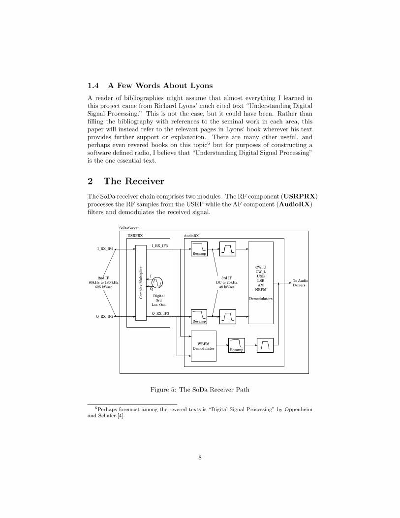
2 The Receiver
The SoDa receiver chain comprises two modules. The RF component (USRPRX)processes the RF samples from the USRP while the AF component (AudioRX)filters and demodulates the received signal.
Resamp
Resamp
3rd IFDC to 20kHz
48 kS/sec
I_RX_IF2
Q_RX_IF2
USRPRX AudioRX
Digital3rd
Loc. Osc.
SoDaServer
CW_UCW_LUSBLSBAM
NBFM
Demodulators
To AudioDrivers
Resamp
WBFMDemodulator
2nd IF80kHz to 180 kHz
625 kS/sec
Com
plex
Mul
tipl
ier
I
Q
I_RX_IF3
Q_RX_IF3
Figure 5: The SoDa Receiver Path
6Perhaps foremost among the revered texts is “Digital Signal Processing” by Oppenheimand Schafer.[4].
8
2.1 The USRPRX Module
The USRPRX module is responsible for shifting the incoming RF stream downto baseband. It maintains a quadrature oscillator that tunes from about 80 kHzto 180 kHz to cover the difference between the desired frequency and the sumof the first and second LO frequencies. The first and second local oscillatorsare tuned so that the frequency of interest is always at least 80 kHz away fromany DC output of the analog mixers, and sufficiently far away from the analogoscillators that the phase noise over the range of interest is greatly reduced fromthe close-in phase noise of the USRP oscillators. (See Section 4.1.2.)
The frequency shifting operation is performed with a quadrature oscillatorand a complex multiplication to convert I RX IF2 and Q RX IF2 into I RX IF3
and Q RX IF3. This is the same operation performed by the digital downcon-verter in the FPGA.7 (See Figure 2.)
I RX IF3 = I RX IF2 · Ilo3 + Q RX IF2 ·Qlo3
Q RX IF3 = Q RX IF2 · Ilo3 − I RX IF2 ·Qlo3
2.2 The AudioRX Module
The AudioRX module demodulates the RF sample stream from the USRPRXunit, and downsamples the stream to match the 48KHz sampling rate of theaudio output device. The audio device itself is driven via the ALSA audiointerface provided by the host computer’s Linux operating system.[5] Figure 5shows the organizational scheme of the AudioRX unit.
For most modes, the input RF stream is downsampled immediately from625 kS/s to 48 kS/s. Next the I and Q channels are passed through a bandpassfilter before the demodulation stage. Demodulation of CW U, CW L, USB,and LSB all follow the same path. The Q channel is passed through a hilberttransformer[3, pp 489-495] to generate a 90 deg phase shift, while the I channelis passed through an all-pass filter with exactly the same delay as the hilberttransformer. The resulting signals are added for CW L and LSB, or subtractedfor CW U and USB to generate a single channel of audio output. Alternatesideband rejection is quite good, in excess of 50 dB, and beyond my ability toaccurately measure it.
Narrowband FM demodulation uses a simple scheme that calculates thederivative of the incoming I and Q channels and normalizes these to the magni-tude of the signal.[3, pp 759-760] This is a fairly inexpensive operation, thoughby no means “high fidelity.” It is much simpler than PLL based solutions.
Wideband FM demodulation uses the same discriminator function as fornarrowband FM, but the demodulation is done on the incoming RF I and Qchannels before downsampling. This is done because much of the energy in awideband FM channel would fall above the nyquist frequency for the 48 kS/saudio stream.
7 The reader may note a confusing change in sign for the terms involving Qlo3. Downcon-verters must invert the sign of the Q channel in order to make the math come out correctly.[3,p 456 ff].
9
In both FM demodulators, the output is followed by a median filter to mit-igate some of the pops and crackles that appear for weak FM inputs.
The demodulator routine produces a stream of audio buffers, each 2304samples long. These are placed on a queue for later dispatch to the ALSA audiooutput. A block is removed from the queue when the audio interface is readyto accept new data.
The oscillator that generates the audio system clock is not locked to anyexternal standard. In fact, it is likely derived from an inexpensive crystal oscil-lator with an accuracy far lower than 100ppm. The USRP however, is lockedto a GPS disciplined oscillator. The discrepancy between the governing clocksfor the two streams means that the audio system can get ahead or fall behindthe USRP.
If the audio system gets ahead of the USRP, there will be a brief gap inthe output audio of up to 48 mS. If the discrepancy is as much as 100 ppm,the audio stream will get one packet ahead of the USRP every 480 seconds. Inpractice, I’ve yet to see this.
For both of the host computers used so far, the audio system fell behind theUSRP. This causes no great upset in the audio channel, but the delay betweenarrival of the signal at the antenna and arrival of the demodulated output at thespeaker grew longer with time. In earlier versions of the program I noticed thatthe audio would fall 10 seconds behind after about 12 hours of continuous use.The AudioRX unit was modified to watch the queue of pending audio buffers.When the queue gets larger than 8 buffers (about 400 mS) each subsequentbuffer sent to the Audio system is trimmed by 1 sample. Truncating the audiobuffers would cause a regular “pop” in the speaker that might become irritating.Rather than truncate the buffer, one sample is removed from a “random” spotwithin each buffer. The pseudo random selection is irregular enough that therate matching correction is undetectable to the ear.
2.3 Filters
SoDa uses digital filters in a number of places both in the receive chain and in thetransmit chain. These are all built using the FFTW3[6] fast fourier transformlibrary. The FFTW3 library is sufficiently fast that any FIR filter of more than10 taps or so is most efficiently implemented in the frequency domain. Thecombination of a highly tuned FFT implementation, and much better memoryaccess patterns with the frequency domain approach made it the logical choice.All filters used in SoDa, including the anti-aliasing filters in the resamplingfunctions, are implemented using the Overlap-and-Save algorithm.[3, pp 716-720] SoDa’s OSFilter class provides automatic constructors for bandpass andlowpass filters and creates the necessary save buffers and FFTW transformplans. There are four pre-defined audio filters of 100 Hz, 500 Hz, 2 kHz, and 6kHz bandwidths. The 100 Hz and 500 Hz filters are centered near 450 Hz, whilethe other two filters have a lower cutoff frequency of about 250 Hz.
10
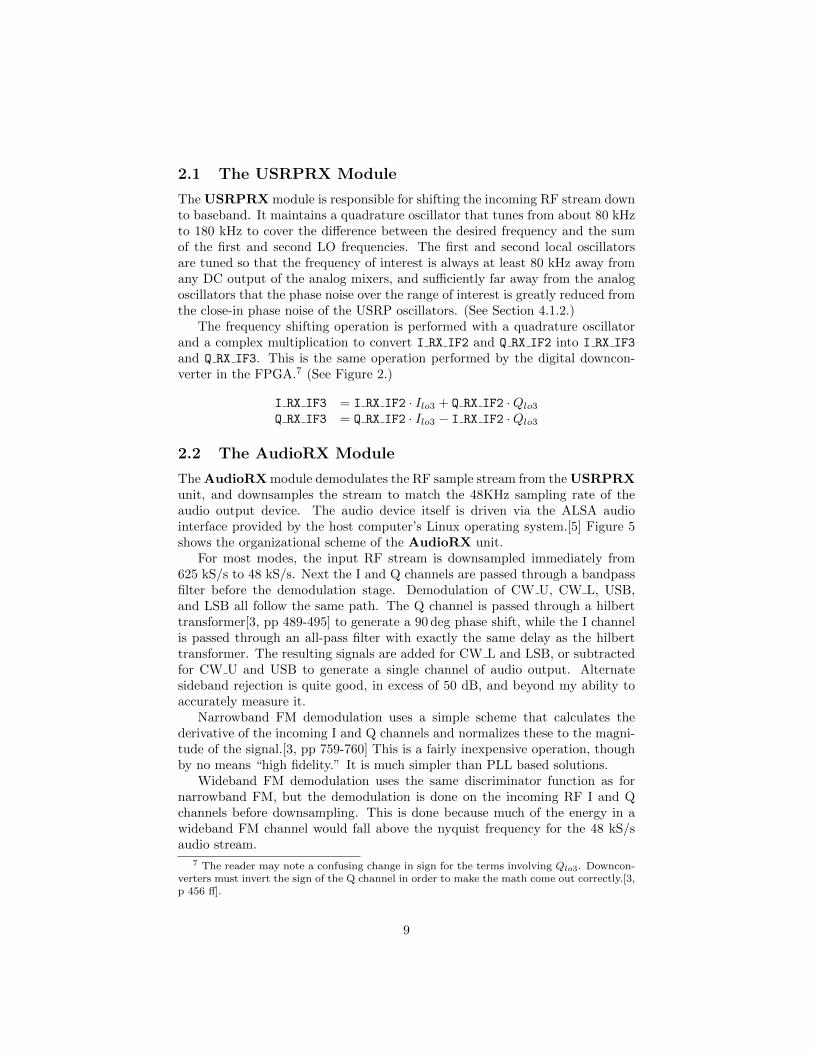
2.4 Sample Rate Conversion
The sample rates at each stage of the chain were selected to minimize the diffi-culty in conversion from one stage to the next.
Buffer sizes were chosen to make the FFT operations efficient, though theywere not chosen to be powers-of-two. The FFTW3 library is quite good atmixed-radix FFTs where the size of the transform is 2a · 3b · 5c · 7d. This makesa buffer size of 30000 samples (for the 625 kS/sec RF stream) and 2304 samples(for the 48 kS/sec audio stream) convenient. The two buffer sizes and the twosample rates are in the ratio of 625
48 .Converting from the RF input stream to the audio stream is done in four
stages where each stage upsamples by a factor of 1, 3, or 4, and downsamplesby a factor of 5. (See Figure 6.)
LPF π/5
DownSample
by 5 LPF π/5
DownSample
by 5
UpSample
by 3
LPF π/5
DownSample
by 5
UpSample
by 4 LPF π/5
DownSample
by 5
UpSample
by 4
625 kSamp/secRF Stream
48 kSamp/secAF Stream
Figure 6: Resampling from RF Sample Rate to AF Sample Rate
Conversion of the transmit stream uses the same resampler code, but up-samples at each stage by a factor of 5 and downsamples by a factor of 1, 3, or4 depending on the rate conversion stage.
3 The Transmitter
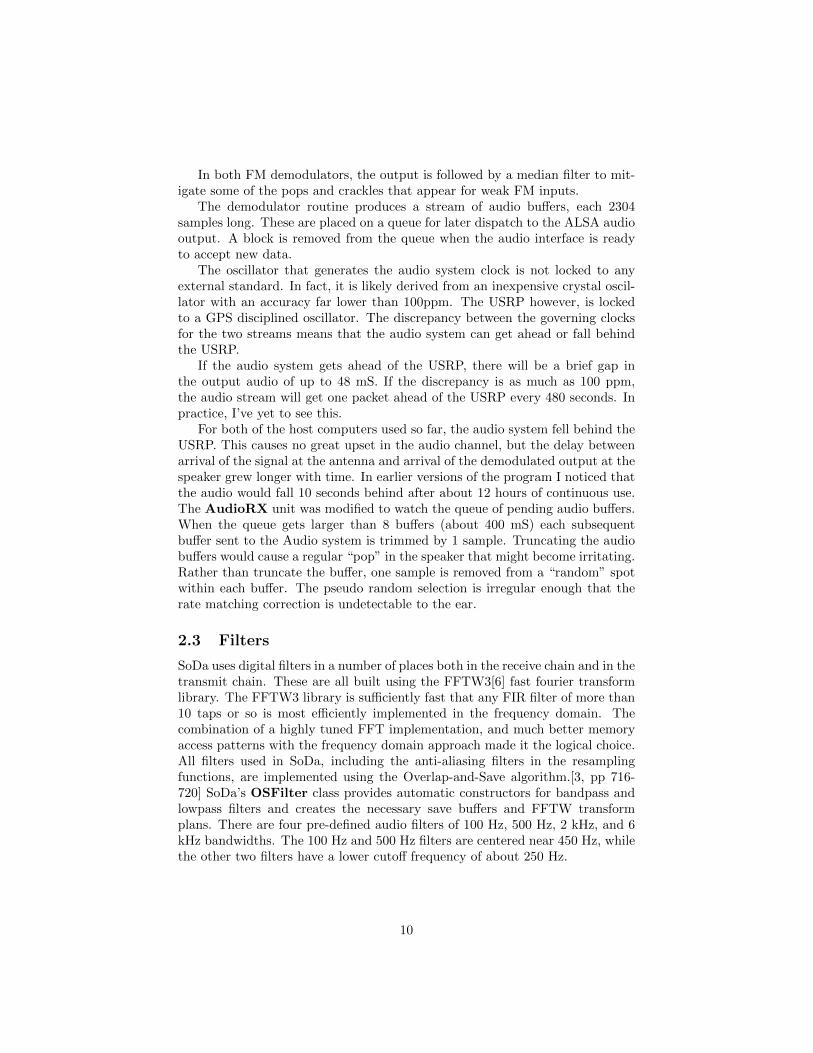
The SoDa transmitter chain comprises three modules. The RF component(USRPTX) forwards a modulation envelope to the USRP transmit block. TheAF component (AudioTX) creates the I/Q channels from a single channel au-dio stream. The CW generation and envelope unit (CWTX) converts incomingstreams of text into shaped pulses that modulate a low frequency carrier in theUSRPTX unit.
3.1 The USRPTX Module
The USRPTX module may be the simplest unit in the SoDa radio. In CWmode, it accepts CW modulation envelopes from the CWTX unit and impressesthem onto a 500 Hz I/Q audio tone. In other modulation modes, it simply passesthe I/Q audio stream (upsampled at the RF sample rate of 625 kS/sec) to theUSRP transmitter.
11
Interp
Interp
3rd IFDC to 20kHz48 kSamp/sec
I_TX_IF2
Q_TX_IF2
USRPTXAudioTX
CW ToneOsc.
SoDaServer
USBLSBAM
NBFM
Modulators
From AudioDrivers
90° shift
CWTX
Text to CW EnvelopeGenerator
CW
SSB/FM
SSB/FM
CW
2nd IFbasebandto 20 kHz
625 kSamp/sec
Figure 7: The SoDa Transmitter Path
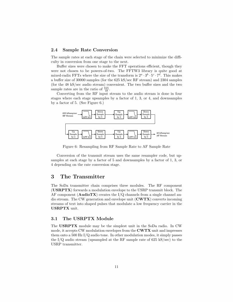
3.2 The AudioTX Module
The AudioTX module is responsible for converting incoming microphone inputat 48 kS/sec to an I/Q stream, and interpolating (upsampling) to 625 kS/sec.In the case of a USB or LSB signal, the Q channel is generated by passingthe input audio through a hilbert transformer. (The I channel is created bypassing the same audio signal through an allpass filter whose delay is matchedto the hilbert transformer.) For LSB transmission, the sign of the Q channel isflipped. In AM mode, the Q channel is set to zero and the audio is copied tothe I channel. SoDa does not yet support FM transmission modes.
3.3 The CWTX Module
The CWTX module converts incoming text streams (on the Control Stream,from the UI process) into morse code pulses. The pulses are shaped and widthsare set according to the currently selected CW speed. CW speed is adjustedon request from the UI process.8 The morse pulses are impressed on a lowfrequency “carrier” by the USRPTX.
8There is a knob in the GUI that causes a message to be sent to the SoDaServer UIthread when the CW speed is adjusted.
12
3.4 Monitoring the CW Sidetone
While the CW transmitter is active, the USRPCtrl will tune the receiverchain to the transmit frequency. This allows the receiver sections of the radioto monitor the outgoing CW signal by listening to the leaked transmit signalinside the USRP box. While the receive chain is in “sidetone” mode, the audiogain is governed by the sidetone gain setting rather than the receive mode audioand RF gain settings.
4 The Controller
The UHD library supplied by Ettus Research is quite complex. In general, itis thread-safe. That is, multiple threads can use the library to access a singledevice. But in practice, allowing multiple threads to make control changes islikely to lead to confusion, if not actual error.
The USRPCtrl process handles all changes to the state of the USRP thatare not associated with either the receive data stream or the transmit datastream. (The USRPRX thread manages its own data stream, as does theUSRPTX thread.) The controller can change RX and TX gain settings, sam-pling rates, transmit/receive switches, the two front-end local oscillators, andthe digital downconverter and upconverter oscillators.
4.1 Tuning
Tuning with a USRP radio is spread out over three stages:
First Stage Analog LO: implemented with a very versatile synthesized os-cillator, the ADF4350[7] from Analog Devices. The chip produces both Iand Q outputs that span the frequency range from about 68 MHz to 2200MHz. The chip can be used as a fractional-N or integer-N PLL synthesizer.Its tuning steps can be as small as a few hundred Hz.
Second Stage Digital Down/Up Converter: implemented as digital oscil-lator within the USRP’s field programmable gate array. The digital oscil-lators can be tuned to sub-Hz resolution.
Third Stage Digital Down Converter: implemented in software as a blockin the USRPRX process. This oscillator can also be tuned to sub-Hzresolution.
4.1.1 Transmit Tuning
Transmit tuning is very straightforward. The UHD library provides a routinethat takes a target frequency as an argument and sets both the first LO (in theADF4350) and the second LO (in the FPGA) to appropriate values. DuringCW U or CW L transmission, the requested frequency is 500 Hz below (forCW U) or above (for CW L) the nominal transmit frequency. For SSB or AMmodes, the requested frequency is exactly the nominal transmit frequency.
13
4.1.2 Receive Tuning
On the receive side, the USRPCtrl process gives more direct guidance to theUHD library, and requests specific tuning settings for the first and second LOs.In each case, the requested receive frequency for the USRP RX chain is set tobe at least 80 kHz below and no more than 180 kHz below the target receivefrequency. This ensures that the DC offset component in any spectrum plots iswell away from the frequency of interest. It also helps to put the analog LO tensof kHz away from the target frequency to reduce the effects of “close in” phasenoise from the PLL oscillator. The upper limit of 180 kHz keeps the third stageLO frequency well below the nyquist frequency of the 625 KS/sec I/Q signalstream.9
Months of experimentation with various tuning schemes showed that thefractional-N tuning supported by the supplied UHD library sacrificed a few dBin receiver sensitivity by raising the noise floor. Especially near the tuned car-rier, spurs at multiples of the reference frequency divided by the fractional-Ndenominator (normally 1024) were quite visible in spectrum plots. Fortunately,the UHD library is open source code, so it was modified to support integer-N tun-ing for the first stage LO on the receiver side. (The difference between integer-Nand fractional-N tuning on the transmit side is negligible.) When linked againsta version of libuhd where integer-N mode is supported, the USRPCtrl processrequests a first LO frequency that is a multiple of 6.25MHz and is below thetarget frequency. The second (digital) LO is set so that the resulting sum isbetween 80 kHz and 180 kHz below the target frequency.
Recent experiments have shown that results approaching those from aninteger-N mode are achievable if the fractional-N settings are chosen such thatthe numerator of the fraction is always zero. This requires some “trial anderror” tuning, as libuhd does not make this information directly visible.
4.2 TX/RX Switching
The USRP was designed to support full duplex communication. In particular,its transmit and receive chains have independent antenna terminals. This ar-rangement is convenient for driving a transverter, as I’ve encountered more thanmy share of problems with T/R switches. Running twin cables (RX labeled witha red band at each end) between the IF and the transverter is more than offsetby the savings in blown-up T/R interfaces.
The WBX module contains several digital I/O pins that can be used asgeneral-purpose I/O lines. The USRP was modified to connect one of themto a relay driver transistor that operates a keying relay. This is used to shortthe transverter’s PTT line to ground during transmit. Putting the relay anddriver transistor between the relatively expensive USRP electronics and the
9 The SoDa design is quite conservative here. Because the stream is represented by bothinphase and quadrature components, the practical upper limit is 500 kHz or so. Futureexperiments will test larger LO offsets.
14
transverter prevents the USRP drivers from being damaged in the event of anaccident (likely) or misconnected cable (certain).
The USRPCtrl process manages the T/R output pin and ensures thatthe transmit PTT line is activated well before a signal is transmitted throughthe TX chain, and is held on until after the USRPTX control process as lefttransmit mode.
5 The User Interface
The SoDaRadio GUI (Graphical User Interface) program and the SoDaServerprogram were built separately for several reasons.
1. The real-time requirements for a GUI are different from and less stringentthan those for the USRP control.
2. Keeping the GUI and the radio parts separate allows for a cleaner andmore modular design.
3. Over time, other GUI schemes might be used to allow access to the radiofrom handheld devices, web browsers, or other GUI instances on remotecomputers.
Figure 8 shows the SoDaRadio GUI during a contact between KB1VC andKW2T on the second weekend of the 2013 10GHz and Up Cumulative Contest.The waterfall diagram shows a distinct streak – KW2T’s CW signal – somewherein the range of 5 to 10 dB above the noise floor.
15
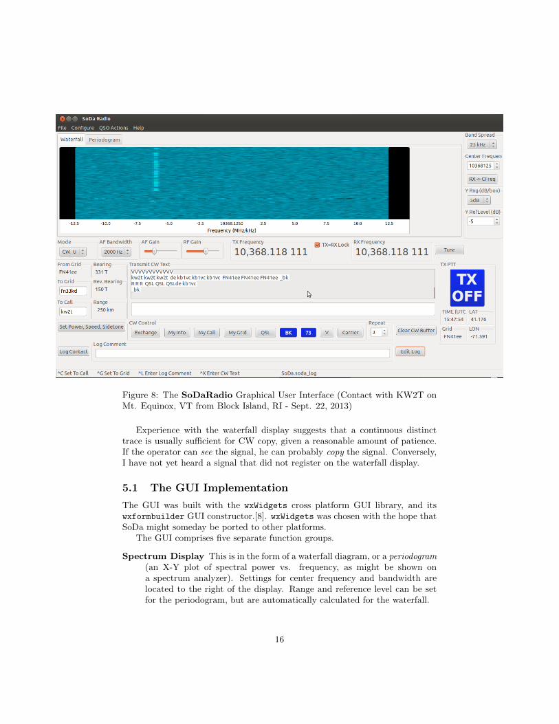
Figure 8: The SoDaRadio Graphical User Interface (Contact with KW2T onMt. Equinox, VT from Block Island, RI - Sept. 22, 2013)
Experience with the waterfall display suggests that a continuous distincttrace is usually sufficient for CW copy, given a reasonable amount of patience.If the operator can see the signal, he can probably copy the signal. Conversely,I have not yet heard a signal that did not register on the waterfall display.
5.1 The GUI Implementation
The GUI was built with the wxWidgets cross platform GUI library, and itswxformbuilder GUI constructor.[8]. wxWidgets was chosen with the hope thatSoDa might someday be ported to other platforms.
The GUI comprises five separate function groups.
Spectrum Display This is in the form of a waterfall diagram, or a periodogram(an X-Y plot of spectral power vs. frequency, as might be shown ona spectrum analyzer). Settings for center frequency and bandwidth arelocated to the right of the display. Range and reference level can be setfor the periodogram, but are automatically calculated for the waterfall.
16
Mode, Tuning, Gain, and Bandwidth Settings These are located in themiddle of the display. Tuning is normally accomplished by clicking on a
point in the spectrum display. Alternatively, the�� ��Tune button will pop-
up a tuning dialog that allows selection of the transmit and/or receive
frequency. The two can be locked together with the�� ��TX=RX Lock
button.
Navigation The To Grid text box combined with this station’s location (theFrom Grid) produces a calculated bearing, reverse bearing, and grid-center-to-center distance in the display to aid in antenna pointing. Infor-mation received from an attached GPS receiver (UTC time and location)are shown below the big PTT switch on the right of the display. The To
Call text box completes the information required to enter a contact intothe log.
CW and PTT The white text box in the lower center of the display allowsfree-form text to be transmitted while in CW mode. The buttons belowCW Control automatically generate text for the standard parts of an ex-change, and can automatically trigger a transition from TX to RX mode
when the exchange has been sent. The blue�� ��TX OFF button activates
the transmitter, and changes itself to a red�� ��TX ON button as a reminder
that the radio is transmitting.
Logging The�� ��Log Contact button at the bottom left of the window creates
a log entry and a snapshot of the waterfall window. An optional comment
may be added to the log. The�� ��Edit Log button pops up a dialog that
allows changes or corrections to be made to the log.
Additionally, the�� ��Set Power, Speed, Sidetone button pops up a dialog box
that allows the operator to change the transmit power, and CW speed andsidetone volume.
The tuning dialog box in Figure 9 presents two more useful features.
The�� ��Ext Ref Enable checkbox enables or disables the external frequency
reference input to the USRP. While the local reference in the USRP is sufficientlyaccurate to position the VHF signal “close enough for amateur use,” the externalGPS reference is extremely useful for the second special feature in the tuningdialog.
The “Transverter LO Cal” function takes advantage of what would otherwisebe a minor annoyance. When the USRP is used with an external microwavetransverter, the transverter’s own local reference oscillator leaks onto the receiveRF path from the transverter back to the USRP. In the case of the Down EastMicrowave 10GHz transverter used here, the harmonic of the transverter LO at1136 MHz does not greatly affect the available dynamic range of the receiver,but it is well above the noise floor. The transverter LO is not slaved to anexternal reference, so it can drift with time and temperature despite careful and
17
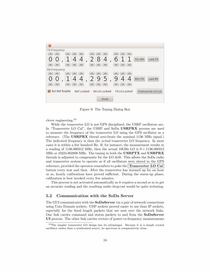
Figure 9: The Tuning Dialog Box
clever engineering.10
While the transverter LO is not GPS disciplined, the USRP oscillators are.In “Transverter LO Cal”, the USRP and SoDa USRPRX process are usedto measure the frequency of the transverter LO using the GPS oscillator as areference. (The USRPRX thread zero-beats the nominal 1136 MHz signal.)The indicated frequency is then the actual transverter LO frequency. In mostcases it is within a few hundred Hz. If, for instance, the measurement results ina reading of 1136.000312 MHz, then the actual 10GHz LO is 9 × 1136.000312MHz or 10224.002808 MHz. The tuning in both the USRPTX and USRPRXthreads is adjusted to compensate for the LO drift. This allows the SoDa radioand transverter system to operate as if all oscillators were slaved to the GPS
reference, provided the operator remembers to poke the�� ��Transverter LO Cal
button every now and then. After the transverter has warmed up for an houror so, hourly calibrations have proved sufficient. During the warm-up phase,calibration is best invoked every few minutes.
This process is not activated automatically as it requires a second or so to getan accurate reading and the resulting audio drop-out would be quite irritating.
5.2 Communication with the SoDa Server
The GUI communicates with the SoDaServer via a pair of network connectionsusing Unix Domain sockets. UDP sockets proved easier to use than IP sockets,especially for the fixed length packets that are sent over the network links.One link carries command and status packets to and from the SoDaServerUI process. The other link carries vectors of power-vs-frequency measurements
10The simpler transverter LO design has its advantages. Because it is a simple crystaloscillator rather than a synthesized source, its spectrum is comparatively clean.
18
from the SoDaServer UI process to the spectrum display in the GUI.Clicking on a spot in the spectrum display, for instance, will create a tune-
request message that is sent from the GUI, over the control link, to the So-DaServer UI process. The UI process then forwards the control request overthe SoDaServer Command Stream where it will be seen by all of the other So-DaServer threads. Threads that are not “interested” in the request (such asthe AudioRX thread) will ignore the command, while the rest will take ap-propriate action. The USRPCtrl thread will convert the tune request messageinto a series of calls to libuhd.
The SoDaServer UI process has no knowledge of the appearance, function,or even location of the GUI. This allows the SoDaServer program to be appliedto other purposes, such as the construction of a spectrum analyzer, or a noisefigure meter. Someday.
6 Operating Experience
SoDa has been used as the IF rig for the KB1VC efforts in the 2012 and 201310GHz and Up Cumulative Contest.
The 2012 effort exposed a number of problems with an early version of theGUI.
• Tuning was extremely awkward as the first GUI did not automaticallyhandle CW offsets. (Clicking on a strong signal peak would tune thereceiver to zero-beat.)
• The early GUI did not have a waterfall chart, and instead presented a plotof spectral density vs. frequency as one might see on an analog spectrumanalyzer. Small signals tend not to deflect the trace sufficiently to allowtheir detection “by eye.”
• The CW keyer interface was extremely awkward. Almost every CW QSOinvolved fumbling for the correct button and occasionally transmitting thewrong call sign.
The 2013 effort saw the introduction of a waterfall plot which helped im-mensely in identifying very weak signals. More importantly, it allowed me topeak the antenna on signals that were “near” the rendezvous frequency, or atleast within the 25 kHz or 50 kHz window. Clicking on a stripe on the waterfallchart automatically tunes both the receiver and the transmitter, accounting forCW offset where necessary.
Between the two contests, I tried out PSK31 operation on the HF bands usingmy FT-817 and FLDIGI, a Linux application for digital radio. The user interfacewas quite well tuned for both contest operation and casual conversation, muchmore so than my own first attempt. While the improved SoDa UI is not asversatile as the FLDIGI interface, it proved workable in the 2013 contest.
The USRP hardware itself has held up well in portable operation, even insome unpleasantly humid (or even torrential) weather. However, the 12VDC
19
to 115VAC inverter – required to power the the 6V DC “wall wart” that camewith the USRP – generated a great deal of noise. A 12VDC to 6VDC converterwas added for the second contest.
Good 12V to 6V DC to DC converters are not general stock components,but Vicor[9] makes a 5V switching regulator that is very quiet and capable ofsourcing 10A. Changing the voltage sense resistive divider on the Vicor PI3302-00-EVAL1 module raised the output from 5 volts to 6 volts. Adding some inputdecoupling eliminated any perceptible power supply noise in the radio.
The new 12VDC to 6VDC converter was a vast improvement, but the changeexposed the huge racket caused by the laptop power supply, also running off ofthe inverter. A 12VDC replacement power supply was even worse, creatingvery broadband noise that got into everything. 11 Next year will see a newsupply for the laptop. In the meantime, the laptop external supply/charger isleft disconnected during contacts. The laptop battery life is sufficient to allowhours of continuous operation without recharging.
The WBX module tunes a very wide range. To preserve this flexibility, ithas no front-end filtering. This makes it susceptible to overload from in-bandand out-of-band signals. As a transverter IF, the transverter filtering was morethan adequate to suppress most interfering sources. (It could not suppress thesignal from nearby VHF radios on the 2 meter liaison frequency. On the otherhand, not many IF radios can.) As a VHF or UHF receiver, preselector andtransmit filters are a must.
7 Conclusion
The SoDa effort achieved its first goal: as a learning experience it was bothchallenging and rewarding. The radio performs well, and is quite good diggingsignals out of the noise. Over four weekends of contest operation and countlesshours in the shack, it has proved itself as a transverter exciter and as an all-modereceiver.
Along the way, the SoDa project has created a set of modular building blocksfor creating other USRP applications. SoDa is available on SourceForge athttp://sodaradio.sourceforge.net/ so that others might try out the EttusUSRP, a very interesting universal software radio peripheral.
References
[1] GNURadio - The Free & Open Software Radio Ecosystem. [Online].Available: http://www.gnuradio.org
11Switching supplies have gotten a bad reputation, but experience with the extremely welldesigned Vicor units, and others, suggests that the bad reputation properly belongs to badlydesigned supplies, or ancient designs from the seventies. There is no need to fear switchers.The N200 employs several of them internally, as do many other modern radio designs.
20
[2] R. Campbell KK7B, “High performance, single-signal direct conversion re-ceivers,” QST, pp. 32–40, Jan 1993.
[3] R. G. Lyons, Understanding Digital Signal Processing, 3rd ed. Boston, MA,USA: Prentice-Hall, 2011.
[4] A. V. Oppenheim and R. W. Schafer, Digital Signal Processing. Prentice–Hall, 1975.
[5] Advanced linux sound architecture (alsa) project homepage. [Online].Available: http://www.alsa-project.org/
[6] M. Frigo and S. G. Johnson, “The design and implementation of FFTW3,”Proceedings of the IEEE, vol. 93, no. 2, pp. 216–231, 2005, special issue on“Program Generation, Optimization, and Platform Adaptation”.
[7] ADF4350 Wideband Synthesizer with Integrated VCO. [Online]. Available:http://www.analog/static/imported-files/data sheets/ADF4350.pdf
[8] J. Smart, K. Hock, and S. Csomor, Cross-Platform GUI Programming withwxWidgets. Upper Saddle River, NJ, USA: Prentice Hall PTR, 2005.
[9] PICOR Cool-Power PI33XX-X0 8V to 36Vin Cool-Power ZVS Buck Reg-ulator Family. [Online]. Available: http://cdn.vicorpower.com/documents/datasheets/Picor/ds pi33xx.pdf
21