soft robotic fingers with embedded ionogel sensors and...
TRANSCRIPT

Soft Robotic Fingers with Embedded Ionogel Sensors and DiscreteActuation Modes for Somatosensitive Manipulation
Ryan L. Truby1,2,∗, Robert K. Katzschmann2, Jennifer A. Lewis3,∗, and Daniela Rus2,∗
Abstract— Soft robotic grippers enable gentle, adaptive, andbioinspired manipulation that is simply not possible usingtraditional rigid robots. However, it has remained challengingto create multi-degree-of-freedom soft actuators with appro-priate sensory capabilities for soft manipulators requiringgreater dexterity and closed-loop control. In this work, weuse embedded 3D printing to produce soft robotic fingers withdiscrete actuation modes and integrated ionogel soft sensorsthat provide proprioceptive and tactile sensing correspondingto each degree of freedom. With new readout electronics thatstreamline the measurement of sensor resistance, we evaluatethe fingers’ sensory feedback through free and blocked dis-placement experiments. We integrate three of our sensorizedfingers together to create a soft manipulator with differentgrasping poses. Finally, we showcase the importance of thefingers’ discrete actuation modes and integrated sensors viaa closed-loop grasping study. Our methods demonstrate anenabling manufacturing platform that can be adapted to createother soft multi-DOF manipulators requiring somatosensoryfeedback for a variety of closed-loop and machine learning-based control algorithms.
I. INTRODUCTION
Recent developments in soft robotics have demonstratedhow compliant materials can be harnessed to drive advancesin robotic manipulation. From gentle [1] and universal [2]object handling to complex, bioinspired actuation motifs[3]–[6], soft robotic manipulators have demonstrated uniquecapabilities compared to traditional rigid manipulators [7].Soft manipulators have widespread potential for future usein automated assembly and packaging, prosthetic devices [8],conservation [9], extreme environments, and much more [7],[10], [11]. However, creating soft robots with multi-degree-of-freedom (DOF) actuation and somatosensory capabilitiesremains a significant hurdle that limits their practical use inthese areas [7], [10], [11].
Most soft robotic manipulators operate via open-loopcontrol [7], [11] and have simple, single-DOF actuation, suchas uniform bending or twisting [10]. Given the simplicity offluidic actuation and molding-based fabrication techniques,fluidic elastomer actuators (FEAs) are a popular platform forproducing soft manipulators. Unfortunately, these techniquesrequire multiple assembly steps, especially when multi-DOFactuators are desired [10]. Closing the control loop on
1Schmidt Science Fellow2MIT Computer Science and Artificial Intelligence Laboratory (CSAIL),
Massachusetts Institute of Technology, Cambridge, MA, USA3John A. Paulson School of Engineering and Applied Sciences, Wyss
Institute for Biologically Inspired Engineering, Harvard University, Cam-bridge, MA, USA
∗Direct email correspondence to: [email protected] (RLT),[email protected] (JAL), [email protected] (DR).
Long contact sensor
Contact sensor leads
Short contactsensor
Long & short curvaturesensors
Tip actuatornetwork
Side view
Top-down
Bottom
Actuatorinlets
Base actuatornetwork
Long contactsensor
Short contactsensor
(d)
Curvature sensor leads
Long curvature sensorShort curvaturesensor
Base
Base BothTip
Arm
Gripper Both
(a) (b)
(c)
Fig. 1. Soft robotic gripper with EMB3D printed soft fingers. (a) Threefingers comprise a soft gripper fixed to a robot arm. (b) Inflating the tip(left), base (center), or tip and base (right) actuator networks enable threemodes of finger bending and (c) different grasps. (d) Schematics of thefinger from side (top), top-down (middle), and bottom-up (bottom) views.Scale bars are 30 mm.
manipulation requires that motion capture systems be presentor sensors be integrated into the soft actuator. If sensors areincorporated, several additional design and fabrication issuesarise (see Background).
Achieving soft somatosensitive manipulation requires anintegrated design and fabrication strategy that streamlinesthe production of soft actuators with discrete actuation modesand integrated sensors. Here, we use embedded 3D (EMB3D)printing [12]–[15] to rapidly create soft, sensorized FEA-based fingers with multiple actuation motifs for soft manip-ulators (Fig. 1). As a demonstration, we print soft fingerswith two discrete fluidic networks that allows for tip, base,and full-finger actuation (Fig. 1b) and multiple graspingmotifs (Fig. 1c). Four soft resistive sensors - two curvatureand two contact sensors - innervate each finger (Fig. 1d).

They are comprised of an organic ionogel that providesreliable sensory feedback without hysteresis in conductivity[15]. Through free and blocked displacement characterizationexperiments, we show that the short and long versions ofthe curvature and contact sensors provide proprioception andtactile sensing corresponding to the finger base and tip DOF,respectively. Finally, with a closed-loop manipulation study,we showcase how multiple grasping modes and contactsensors can improve the success of autonomous grabbingof objects. While we showcase one finger and gripperdesign, our platform enables the creation of a variety ofsoft, complex robotic manipulators for applications requiringsomatosensory feedback that may be difficult or impossibleto make with molding strategies alone. Altogether, our workpresents the following contributions:
1) A first design for a fully 3D printed soft finger withindividually addressable degrees of freedom and cor-responding proprioceptive and tactile sensors,
2) A new ionogel sensor readout strategy compatiblewith a wide array of ionically conductive sensors thatsimplifies determination of resistance change, and
3) A closed-loop grasping study with soft grippers usingmultiple actuation modes and soft sensors.
II. BACKGROUND
Fabricating FEA-based soft robots with integrated sensorsand multi-DOF actuation requires many steps. Prior workhas used molding techniques to make soft quadrupeds [16],swimming fish [17], tentacle-like actuators [4], and hand-likemanipulators [6], [18] with several DOF. By contrast, 3Dprinting offers a promising approach for rapidly designingand fabricating complex soft actuators [19]. Several light-and ink-based printing techniques have recently emergedfor directly building multi-DOF soft fingers [5], legs [20],grippers [21], and integrated robotic systems [13], [22], [23].
FEAs can be innervated with rigid bend and pressuresensors [21], [24] or, alternatively, soft sensors based onliquid metals [25]–[27], conductive nanoparticle-polymercomposites [28], [29], hydrogels [30]–[33], or elastomericwaveguides [8], [34]. However, conventional rigid sensors donot mechanically interface well with the soft elastomers ofFEAs, nor do the rigid components required for elastomericwaveguides. Liquid metal sensors are unreliable due to thepotential displacement of their passivating oxide layers overtime [25]. Water evaporates from aqueous hydrogels [35].Finally, conductive polymer composites have inconsistentconductivities due to the conductive filler’s dynamic perco-lation network [14].
Recent work has suggested that organic ionic liquids arepromising materials for robust, reliable soft robotic sensors[15], [36], [37]. However, the ionic and hygroscopic natureof the printed ionogel sensors necessitates low-voltage, ACreadout strategies to bypass the effects of charge migrationtowards the electrodes and electrolytic side reactions in thesensors [31]. Prior embodiments with ionic sensors haverelied on various signal processing strategies to measurechanges in sensor impedance [15], [30], [31], [36], [37],
but these methods require specialized hardware, intrinsicallylimit sampling rate, and/or present computational burdensthat reduces their practicality.
Embedded 3D (EMB3D) printing is a freeform fabri-cation method introduced by Wu and Lewis [12], whichenables rapid design of soft, highly stretchable strain sen-sors [14], entirely soft robots [13], and soft actuators withintegrated ionogel sensors [15] (Fig. 2). In EMB3D printing,one directly extrudes functional viscoelastic inks into un-crosslinked, viscoplastic matrix materials [38], which can becomposed of various elastomer formulations. The inks impartembedded functionality (e.g., fluidic networks for actuation[13], [15] and conductive features for sensing [14], [15]),while the elastomeric matrix materials cure to provide thefinal mechanical properties of the part. The matrix materialsare poured into molds that define the overall geometry ofthese devices.
III. SOFT MANIPULATOR DESIGN
A. Design Overview
Inspired by our bodies’ sensory capabilities and manualdexterity, we designed a soft robotic gripper comprised ofthree FEA-based fingers possessing discrete actuation modeswith soft proprioceptive and tactile sensors corresponding toeach DOF in actuation. While our methods can be used tocreate actuators with an arbitrary number of free-form sen-sors and actuator networks, the devices presented in this work(Fig. 1d) have two FEA networks, a base and tip actuatornetwork, that drive bending of the base and tip regions ofthe finger. The fingers’ ionogel sensors, have a resistance,RS , given by RS = ρ ∗ (l/A), where ρ is the resistivity ofthe ionogel ink, l is the length of the sensor, and A is thecross-sectional area of the sensor trace. As the sensors aredeformed, RS changes. For prioprioception, short (SCurve,S)and long curvature (SCurve,L) sensors span the length ofthe base and tip actuator networks, respectively. Inflatingthe fingers results in elongation of the curvature sensors:SCurve,S is designed to increase in RS only during inflationof the base actuator network, while SCurve,L undergoes thegreatest change in RS when the full finger is inflated. Short(SContact,S) and long contact (SContact,L) sensors beneaththe fingertip provide tactile sensing when these features arecompressed by contact pressures. SContact,L is designed toindicate when contact has been made at the very tip of the
Fugitiveink
Sensorink
Mold layer 1
1) 2) 3)
Mold layer 2 Mold layer 3
Fig. 2. EMB3D printing a sensorized soft finger. (1) The dorsal matrixis cast into the first mold layer for printing the curvature sensors with thesensor ink. (2) The second mold layer is added, and the actuator matrixis poured in for printing the actuator networks with the fugitive ink. (3)The final mold layer is added, the anterior matrix is added, and the contactsensors are printed. All sensor leads and actuator inlets are printed in theactuator matrix.

finger, and SContact,S provides feedback when contact ismore proximal from the tip (Fig. 1d).
Given their complex form and multi-material composition,we used EMB3D printing to fabricate our soft fingers. Weprint the soft sensors from an organic ionogel-based sensorink to ensure stable, reliable perception with hysteresis-freeconductivity. Finally, we designed new readout hardware forstreamlined measurement of changes in sensor resistance.
B. Embedding Sensors and Actuators into Soft Fingers
The EMB3D printing technique and material sets used tomanufacture our soft fingers are described in detail in ourprior paper [15]. Briefly, fugitive and sensor inks are directlyextruded into uncured elastomeric matrices through finenozzles to create free-form fluidic and conductive featuresfor actuation and sensing (Fig. 2). The fugitive ink is a vis-coelastic gel of Pluronic F127 (Sigma, 25 wt% in deionizedwater) that exhibits a solid-to-liquid transition around 2-5C[12]. The sensor ink is an organic ionogel comprised of 1-ethyl-3-methyl-imidazolium ethyl sulfate (Sigma) filled with6 wt% fumed silica particles (Aerosil 380, Evonik), whichimpart the appropriate yield stress needed for printing [15].
Three matrix materials referred to as the dorsal, actua-tor, and anterior matrices are formulated from Ecoflex 10,SortaClear 40, and Ecoflex 30 silicone elastomers (Smooth-on), respectively. A cure retarder (Slo-Jo) and thixotropicadditive (Thivex, both from Smooth-On) are added to impartthe shear-thinning, yield-stress behavior needed for EMB3Dprinting [15], [38]. During printing, the matrices are pouredsequentially into a multi-layer mold assembly that sets thefingers’ shape (Fig. 2). The curvature sensors are first printedin the dorsal matrix. A mold layer is added, and the actuatormatrix is poured in. We print the two actuator networksand sensor leads in this matrix. Finally, we add anothermold layer, pour in the anterior matrix, and print the contactsensors [15].
Each finger is printed in approximately 90 min, afterwhich it cures overnight for approximately 12 h. The fingersare then cured for 4 h at 80C and refrigerated for 1 hto liquefy the fugitive ink. Two 22-gauge nozzles (EFDNordson) with Luer-lock fittings are inserted into the fingers’actuator matrix, through their back end, and into the actuatornetwork inlets. The liquified fugitive ink is aspirated witha syringe to empty the actuator networks. Ice-cold wateris filled into the actuator networks to remove any PluronicF127, and residual water is removed by heating the fingersin an oven for 2 h at 80C.
Before use, soft fingers are wired by inserting custom leadsinto each sensor through the actuator matrix and into thesensor inlets. The leads are formed by soldering the ends of28 gauge, rubber-coated wire to short nickel-plated stainlesssteal needles with gold electroplated tips and header pinsfor insertion into our readout hardware. Silicone tubing forpressurized air is fixed via the Luer lock nozzle in each ofthe actuator network inlets. The fingers are inflated usinga MATLAB-controlled, pneumatic valve manifold (Festo)
MATLAB via USB Data Acquisition Unit
Frequency-to-VoltageConverter
(a)
63
1
4
2
8
7LM2917
5
C2
C3
R3
R4
Vcc
VconvRelaxationOscillator
-V
+V
TLV2362C1
R1 R2
RsVosc
Ionogel sensor, RS
0 0.005 0.01 0.015 0.02Time (sec)
-1
0
1
Voltage
(V)
0 0.005 0.01 0.015 0.02
Time (sec)
0
2
4
Voltage
(V)
1 MΩ680 kΩ
820 kΩ560 kΩ 5.1 MΩ
3 MΩ2 MΩ
(b)
(c)
(d)Fit (R2 = 0.9785)
Fig. 3. Readout scheme for the embedded sensor networks. (a) Flowchart and electronics schematic for determining the resistance of an ionogelsensor, Rs. (b) The relaxation oscillator produces a signal, Vosc, a squarewave with Rs-dependent period changes. Vosc for a 1 MΩ resistor isshown. (c) Various output voltage signals, Vconv , are shown for variousresistor values from the circuit’s frequency-to-voltage converter. (d) A plotof measured versus real resistance values shows that the resistance valuesof RS are converted reliably by the readout electronics. The slope of thelinear fit is 0.877; the intercept is 0 kΩ.
capable of independently supplying up to 200 kPa pressurefrom 16 different regulators.
C. Readout Electronics for Embedded Sensor Networks
Our new sensor readout strategy, shown schematically inFig. 3a, expands on previous approaches using low-operatingvoltage relaxation oscillators to measure resistance change,∆RS , of a sensor via changes in period of the oscillator’soutput voltage, Vosc [31]. Briefly, an ionogel sensor is theresistor RS in the relaxation oscillator’s RC circuit (Fig. 3a).The oscillator output, Vosc, has the form of a square wavealternating between ±1.2V, the voltage (+V, -V) poweringour op-amp (Texas Instruments TLV2362). The period, T ,of Vosc is
T = 2RsC1ln(1 −B
1 +B) (1)
where B = R1/(R1 + R2), C1 is the capacitor in the RCcircuit, and R1 and R2 are the resistors in the oscillator’s
Schmitt trigger. ∆RS = RS − RS,0 can be determined bymeasuring ∆T = T −T0, where RS,0 is the initial resistanceof the sensor, and T0 is the initial period of Vosc.
To avoid complex signal processing techniques that havepreviously been employed to solve for ∆T [31], [37],we have added a frequency-to-voltage (f-to-V) converter inseries with the relaxation oscillator to simplify the determi-nation of ∆RS . The converter’s output voltage, Vconv , cansimply be read by a data acquisition unit (DAQ) (Fig. 3a).To interpret Vconv , we first note that the frequency of Vosc isfosc, where fosc = T−1. Vconv is set by VCC (9 V) , whichpowers the f-to-V converter (Texas Instruments LM2917),and the passive components R3 and C2:
Vconv = R3C2VCCfosc (2)
Substituting (1) into (2) shows that RS is given by
RS =R3C2VCC
2C1Vconvln( 1−B1+B )
(3)
We designed a custom PCB with 12 copies of the elec-tronic circuit in Fig. 3a for reading 12 soft sensors (i.e.,for 3 fingers with 4 sensors per finger). Table I includesthe passive component values required for our sensors. Dataacquisition was performed over USB with the DAQ (NationalInstruments USB-6212) at a sampling frequency of 25 kHz.Calculating ∆RS was calculated in real-time with MATLABusing (4), with RS,0 as the initial resistance measurementof undeformed sensors. Fig. 3b shows an example of Voscobtained with our readout hardware for RS of 1 MΩ. Thesignal is in good agreement with (1), and Fig. 3c showsseveral examples of Vconv obtained for various resistors usedas RS . As expected from (2) and (3), RS and Vconv areinversely related. Using (4) and Vconv , we measured theresistance of the model RS values. A plot of measured versusreal RS values and a linear fit to the data shown in Fig. 3dconfirm reliable readout of RS values using our new readouthardware for ionogel sensors.
D. Soft Finger Characterization
The fingers are characterized under free and blockeddisplacement. For these experiments, a finger is fastenedinto a laser cut acrylic mount. Fingers are actuated byinflating the actuator networks in 10 kPa intervals every 30sec. After inflation with the maximum pressure of 200 kPa,the actuator is deflated at 10 kPa intervals every 30 sec.Photographs are obtained, along with sensor readouts for 5ms at 25 kHz, once a test pressure has held for 30 sec. Forblocked displacement, short and long acrylic mounts were
TABLE IVALUES OF PASSIVE COMPONENTS FOR SENSOR READOUT
ELECTRONICS
Sensor R1 R2 R3 C1 C2 C3
SContact,S 680 Ω 10 kΩ 330 kΩ 10 nF 1 nF 1 µFAll others 680 Ω 10 kΩ 330 kΩ 4.7 nF 1 nF 1 µF
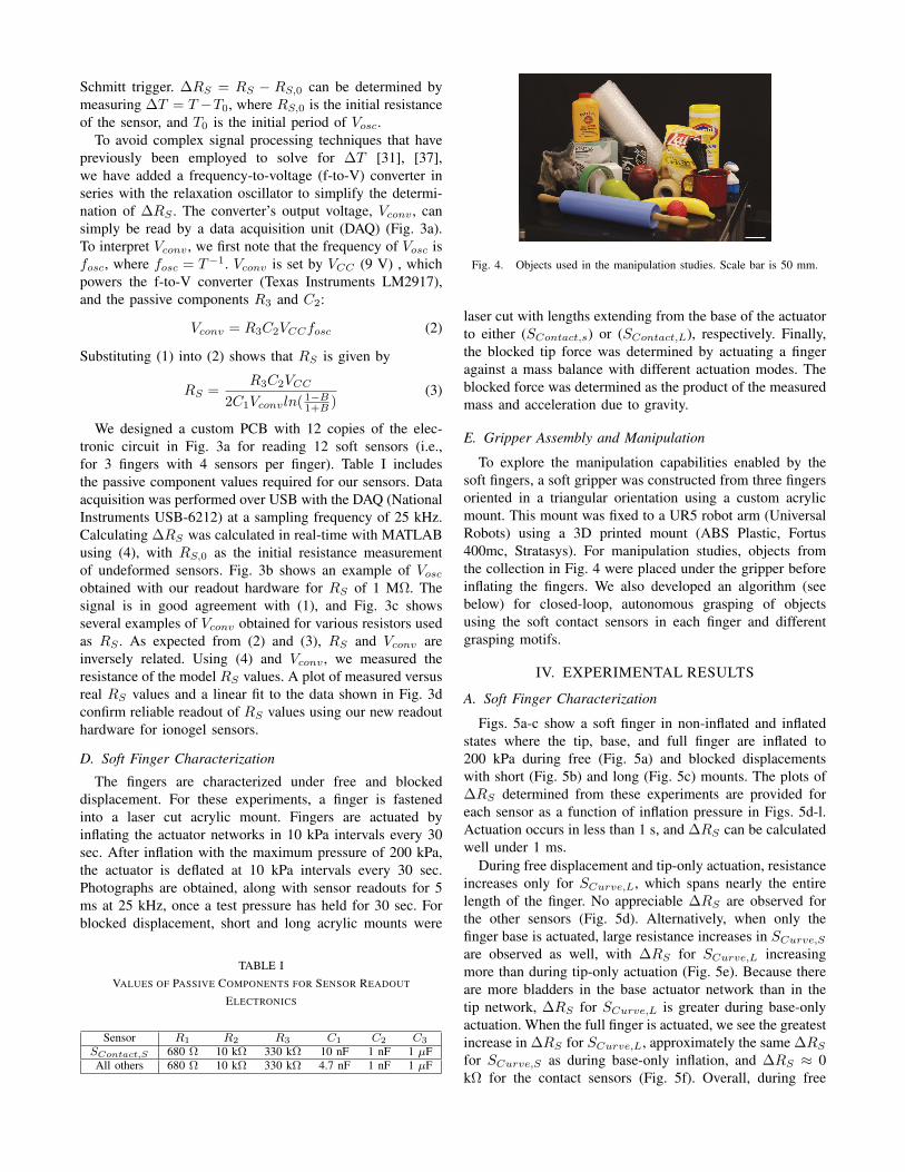
Fig. 4. Objects used in the manipulation studies. Scale bar is 50 mm.
laser cut with lengths extending from the base of the actuatorto either (SContact,s) or (SContact,L), respectively. Finally,the blocked tip force was determined by actuating a fingeragainst a mass balance with different actuation modes. Theblocked force was determined as the product of the measuredmass and acceleration due to gravity.
E. Gripper Assembly and Manipulation
To explore the manipulation capabilities enabled by thesoft fingers, a soft gripper was constructed from three fingersoriented in a triangular orientation using a custom acrylicmount. This mount was fixed to a UR5 robot arm (UniversalRobots) using a 3D printed mount (ABS Plastic, Fortus400mc, Stratasys). For manipulation studies, objects fromthe collection in Fig. 4 were placed under the gripper beforeinflating the fingers. We also developed an algorithm (seebelow) for closed-loop, autonomous grasping of objectsusing the soft contact sensors in each finger and differentgrasping motifs.
IV. EXPERIMENTAL RESULTS
A. Soft Finger Characterization
Figs. 5a-c show a soft finger in non-inflated and inflatedstates where the tip, base, and full finger are inflated to200 kPa during free (Fig. 5a) and blocked displacementswith short (Fig. 5b) and long (Fig. 5c) mounts. The plots of∆RS determined from these experiments are provided foreach sensor as a function of inflation pressure in Figs. 5d-l.Actuation occurs in less than 1 s, and ∆RS can be calculatedwell under 1 ms.
During free displacement and tip-only actuation, resistanceincreases only for SCurve,L, which spans nearly the entirelength of the finger. No appreciable ∆RS are observed forthe other sensors (Fig. 5d). Alternatively, when only thefinger base is actuated, large resistance increases in SCurve,S
are observed as well, with ∆RS for SCurve,L increasingmore than during tip-only actuation (Fig. 5e). Because thereare more bladders in the base actuator network than in thetip network, ∆RS for SCurve,L is greater during base-onlyactuation. When the full finger is actuated, we see the greatestincrease in ∆RS for SCurve,L, approximately the same ∆RS
for SCurve,S as during base-only inflation, and ∆RS ≈ 0kΩ for the contact sensors (Fig. 5f). Overall, during free

0 100 2000
500
1000
1500
Inflation Pressure (kPa)
ResistanceChange(kΩ)
SCurve,LSCurve,SSContact,SSContact,L
Tip
0 100 2000
500
1000
1500
Inflation Pressure (kPa)
ResistanceChange(kΩ)
SCurve,LSCurve,SSContact,SSContact,L
Tip
0 100 2000
500
1000
1500
Inflation Pressure (kPa)
ResistanceChange(kΩ)
SCurve,LSCurve,SSContact,SSContact,L
Tip
0 100 2000
500
1000
1500
Inflation Pressure (kPa)
ResistanceChange(kΩ)
Base
0 100 2000
500
1000
1500
Inflation Pressure (kPa)
ResistanceChange(kΩ)
Base
0 100 2000
500
1000
1500
Inflation Pressure (kPa)
ResistanceChange(kΩ)
Base
0 100 2000
500
1000
1500
Inflation Pressure (kPa)
ResistanceChange(kΩ)
Both
0 100 2000
500
1000
1500
Inflation Pressure (kPa)
ResistanceChange(kΩ)
Both
0 100 2000
500
1000
1500
Inflation Pressure (kPa)
ResistanceChange(kΩ)
SContact,L*Both
Tip: 200 kPaBase: 0 kPa
Tip: 0 kPa,Base: 0 kPa
g
Tip: 200 kPaBase: 200 kPa
Tip: 0 kPaBase: 200 kPa
(a)
Tip: 0 kPaBase: 0 kPa
Tip: 200 kPaBase: 0 kPa
Tip: 0 kPaBase: 200 kPa
Tip: 200 kPaBase: 200 kPa
g(b)
Tip: 0 kPaBase: 0 kPa
Tip: 200 kPaBase: 0 kPa
Tip: 0 kPaBase: 200 kPa
Tip: 200 kPaBase: 200 kPa
g
(c)
(d)
(g)
(j)
(e)
(h)
(k)
(f)
(i)
(l)
Fig. 5. Free and blocked displacement characterization of soft sensorized fingers. (a-c) Photographs of a soft finger in non-inflated (left) and variousmaximum inflation states for tip (center-left), base (center-right), and full (right) actuation modes during (a) free displacement and blocked displacementwith the (b) short and (c) long mounts, whose edges are indicated by the red arrows. Scale bars represent 25 mm; g indicates acceleration due to gravity.(d-l) Resistance change, ∆RS , versus inflation pressure is provided during inflation-deflation cycles (indicated by filled/open circles, respectively) forthe long (SCurve,L) and short curvature (SCurve,S ) and short (SContact,S ) and long contact (SContact,L) sensors during (d-f) free displacement andblocked displacement with the (g-i) short and (j-l) long mounts. Plots correspond to ∆RS during (d, g, j) tip, (e, h, k) base, and (f, i, l) full-finger actuation.In (l), ∆RS for SContact,L is scaled by a factor of 0.2 (to idenically scale axes across subfigures). (n = 3, error envelopes represent standard deviation.)
displacement of the finger in tip-only, base-only, and full-finger actuation, we observe that (i) the maximum ∆RS forSCurve,L are approximately 400 kΩ, 600 kΩ, and 1100 kΩ,and (ii) the maximum ∆RS for SCurve,S are approximately0 kΩ, 1000 kΩ, and 1000 kΩ, respectively.
The soft fingers generate a force at their tip when inflated,and higher inflation pressure produces higher blocked force.We observe a maximum blocked force of approximately 550mN generated at the tip during full-finger actuation (Fig. 6).Tip-only actuation did not provide measurable forces, andbase-only actuation generated slightly lower blocked forceswith inflation pressure. When the fingers are actuated againstthe blocking mounts, we see that the forces generated by thefinger result in reduced finger bending (Figs. 5b,c).
During tip-only actuation with the short mount, we seethe finger tip wraps around the mount’s edge (Fig. 5b).Consequently, ∆RS only increases appreciably for SCurve,L
0 100 2000.0
0.2
0.4
0.6
Inflation Pressure (kPa)
BlockedForce(N) Tip+Base
Base
Fig. 6. Blocked force characterization. Blocked force versus inflationpressure during inflation (filled circles) and deflation cycles (open circles) ofthe base actuator network and full finger. (n = 3, error envelopes representstandard deviation.)
(Fig. 5g), with a similar magnitude to that for tip-onlyactuation in free displacement (Fig. 5d). During base-onlyactuation against the short mount, the finger presses directlyinto the mount, compressing SContact,S and driving anincrease in its resistance to approximately 600 kΩ at 200kPa (Fig. 5h). We also see a slight increase in ∆RS forSContact,L, and a clear increase in ∆RS for SCurve,S (Fig.8c). Full-finger actuation generates the most force against theshort mount, driving higher increases in ∆RS for SContact,S
and SCurve,L, with a maximum ∆RS for SContact,S ofabout 1000 kΩ at 200 kPa (Fig. 5i). Compared to full-finger actuation in free displacement (Fig. 5f), ∆RS slightlydecreases for SCurve,L and nearly halves for SCurve,S duringfull actuation against the short mount because bending isconstrained, especially at the finger’s base region.
Finger bending is restricted even more by the longmount (Fig. 5c). Tip-only actuation drives compression ofSContact,L, increasing its resistance, and also slightly in-creases ∆RS for SCurve,L (Fig. 5j). Base-only actuationalso drives the tip against the long mount. Since base-only actuation generates a higher blocked force than tip-only actuation, we observe even higher increases in ∆RS
for SContact,L (Fig. 5k). Finally, the greatest ∆RS forSContact,L is measured at approximately 3500 kΩ for full-finger actuation against the long mount at 200 kPa (Fig. 5i).SCurve,S does not change in resistance appreciably since themount does not make contact with its region of the finger.Finally, the curvature sensors increase in resistance (Fig. 5i),but to a lesser extent than both free (Fig. 5f) and blockeddisplacement with the short mount (Fig. 5i).

To summarize, our characterization results demonstratethat the curvature sensors provide regional proprioceptionfor each network, with SCurve,S only appreciably changingif the base region of the actuator is bending. The contactsensors provide regional tactile sensing, with SContact,S
and SContact,L sensitive to compression near the end ofthe base and tip actuator networks, respectively. Altogether,these sensors provide feedback on the state and deformationsof each DOF in our soft fingers, enabling somatosensitivemanipulation.
B. Object GraspingOur 3-finger gripper provides different grasp motifs during
base-only and full-finger actuation (Fig. 7). Examples of ourgripper holding objects are shown in Fig. 8. These objectswere hand-fed to the gripper, which inflated around themwithout sensory feedback. When grasping with base-onlyactuation, the gripper’s fingers hold the object with a largerportion of the tip pressing against the object, increasing op-portunities for both contact sensors to increase in resistance.When the full finger is inflated, we tend to see the gripperhold objects by just the fingertips, only increasing ∆RS forSContact,L (Figs. 1c, 9a-b) [39]. Some objects, like thosein Fig. 8c, can be held by our gripper when positioned inspecific orientations before finger actuation. These objectshad a thin or high-aspect ratio profile, were too heavy, and/orwere either much larger than the gripper or too small tohold. Grasping results with base-only and full actuation ofthe fingers at 140 kPa are provided in Table II for all objectsin Fig. 4. Items that were successfully gripped in both caseswere lightweight and easy for the gripper to pick up just bythe fingertips. While we chose a moderate inflation pressurefor all manipulation studies, the gripper could hold all of theitems with full-finger inflation at pressures above 180 kPa.
C. Closed-Loop Object PickingWhen our gripper grabs with full-finger actuation, the
fingers rarely hold objects right against both contact sensors.By contrast, good contact between the contact sensors andan object can occur with base-only actuation (Figs. 1c, 8a-b), increasing both contact sensors’ resistances. However,depending on how contact is made with an object, fullactuation can generate sufficiently high contact forces toincrease resistance of both contact sensors, even though theobject is not pressing directly against both.
Fig. 7. Examples of manipulator poses. Photographs of the soft gripperduring no (left), base-only (center), and full-finger actuation at inflationpressures of 140 kPa. Scale bar is 15 mm.
Base
(a) (c)
Base
Both
Both
(b)
Fig. 8. Examples of object grasping. (a-b) Examples of grasping posesare shown for holding a toy strawberry (a) and pear (b) during base-only(left) and full-finger actuation (right). (c) Examples of objects that can begrasped by the soft gripper with appropriate pre-grasp orientation. Inflationpressure is 140 kPa in each photograph. Scale bars are 15 mm.
To showcase the value of having discrete control over baseand tip actuation of our fingers during autonomous, closed-loop grasping, we developed Algorithm 1 to autonomouslygrab an object placed underneath our gripper. The generalidea is to use base-only or full finger actuation to probefinger contact and guide finger placement around the objectsuch that the fingers were able to robustly grab and lift it.
With Algorithm 1, we attempted to grab each object in Fig.4. Briefly, the gripper moves down over an object on a table,inflating the fingers via base-only or full actuation to probewhether a finger has made contact with the object. Contactwith a finger is noted when both SContact,S and SContact,L
have exceeded a critical resistance change, ∆RS,crit, whichis 8 kΩ and 20 kΩ, respectively. We use this rule to guidethe gripper to a proper length down the object for successfullifting off the table. If all three fingers have made contactduring the grasp attempt, then the fingers are inflated fully,and the gripper moves upward to lift the object off the table.
TABLE IISUMMARY OF GRASPING RESULTS AT 140 KPA
Grasping Motif Plush Toy Lab Wipes Baby Powder Bubble Wrap Soda Can ChipsBase-only Actuation Fail Success Fail Success Success SuccessFull-finger Actuation Success Success Success Success Success Success
Grasping Motif Pear Apple Banana Strawberry Dish Brush Baking PinBase-only Actuation Success Success Fail Success Fail FailFull-finger Actuation Success Success Success Success Success Fail
Grasping Motif Cleaning Wipes Cube Big Tape Small Tape Coffee Mug Zip TiesBase-only Actuation Fail Success Fail Success Success FailFull-finger Actuation Fail Success Fail Success Success Fail

Algorithm 1 Closed-Loop Object Picking1: Move to gripper’s starting height2: while < 3 fingers have made contact & gripper can move
down 20 mm do3: while Inflation pressure <140 kPa do4: Increase actuation pressure by 10 kPa, using5: base-only or full-finger actuation6: if Finger N’s contact sensors are >∆RS,crit then7: Finger N made contact8: if < 3 fingers have made contact then9: Deflate all fingers & move gripper down
10: 20 mm if able to11: if < 3 fingers made contact during grab attempt then12: if 2 fingers made contact then13: Inflate fingers to 140 kPa (full actuation), lift to14: pick up off table15: else Lift non-inflated gripper to starting height16: else Inflate fingers at 140 kPa (full actuation), lift to17: pick up off table
If the gripper has moved down as far as it safely can andtwo fingers made contact at the end of the grasp attempt, westill fully actuate all fingers, and the gripper will try to liftthe object off the table. Fig. 9 shows photographs from trialswhen no item is present (Fig. 9a) or when a plastic appleis under the gripper, where base-only (Fig. 9b) or full-fingeractuation (Fig. 9c) is used to probe for finger contact. Bypositioning the gripper for a grab using base-only actuationfirst, we observed that the robot arm was able to position thegripper further down the apple to ensure a more robust graband, thus, successful lift. Results from closed-loop graspingtrials are provided in Table III for other objects and showthat selective control over finger actuation can enable moresuccessful, grabs guided by tactile feedback. The study doesnot include the items that could not be held during base-onlyactuation at 140 kPa (see Table II). Items that were difficult topick up, including those that were challenging for our gripperto hold during open-loop grasping, were too thin, heavy, orshort for our current set-up and gripper design. Again, wechose a moderate inflation pressure for these studies, andhigher pressures enabled us to lift some of the other objects.
V. CONCLUSIONS AND FUTURE WORK
Our work represents a first study in fabricating, charac-terizing, and utilizing multi-DOF, soft robotic fingers withembedded soft sensors for closed-loop, somatosensitive ma-nipulation. The fingers have two degrees of freedom enabledby base and tip actuator networks and four ionogel sensors
Fig. 9. Examples of autonomous grabbing. Photographs of the gripperusing Algorithm 1 to autonomously pick up a toy apple. (a) With no applepresent, the gripper periodically inflates and probes downward for an object.The fourth image shows a non-actuated gripper moving back to its startingheight. (b,c) Photographs illustrate the results when (b) base-only or (c)full-finger actuation are used to probe contact. Here, the first images showa representative probing actuation. The second image shows the graspingattempt at which contact in all fingers has been made. The small whitearrows show how the fingers make contact with the surface of the apple atthis step. The third image shows all fingers fully inflated, and the last showsthe result as the robot lifts upward. In (a)-(c), the large arrows in the fourthimage indicate that the gripper is raising upwards. Scale bar is 15 mm.
that provide discrete proprioceptive and tactile senses thatcorrespond to each DOF. We made our soft robotic fingersusing a versatile additive manufacturing technique known asEMB3D printing that allows one to arbitrarily pattern theactuation, sensory, and elastomeric features required for ourfinger design in a modular way. Finally, we developed analgorithm for our soft gripper to autonomously grasp objectsusing its discrete actuation modes and embedded sensors.
We are now actively pursuing new multi-DOF, sensorizedsoft actuator designs using these methods to create morecomplex types of dexterous, soft robotic manipulators. Softmanipulator designs that we are exploring have differentfinger numbers, orientations, designs, and sensing motifsthan the gripper presented here. Working with establishedalgorithms in grasp planning with soft grippers [40] andobject recognition [29], we aim to develop soft robots withadvanced manipulation capabilities that will be useful inmyriad applications.
TABLE IIISUMMARY OF CLOSED-LOOP GRASPING RESULTS AT 140 KPA
Experiment Plush Toy Lab Wipes Soda Can Chips Cube Coffee Mug Pear AppleGrasp Guided by Full-Finger Actuation Success Fail Success Success Fail Fail Fail FailGrasp Guided by Base-Only Actuation Success Success Success Success Success Success Success Success

ACKNOWLEDGMENTR.L.T. is supported by the Schmidt Science Fellows pro-
gram, in partnership with the Rhodes Trust. J.A.L. is sup-ported by the National Science Foundation (NSF) through theHarvard MRSEC (DMR-1420570) and the GETTYLAB. Theauthors gratefully acknowledge additional support throughthe NSF EFRI (1830901).
REFERENCES
[1] F. Ilievski, A. D. Mazzeo, R. F. Shepherd, X. Chen, and G. M.Whitesides, “Soft Robotics for Chemists,” Angewandte Chemie -International Edition, vol. 123, pp. 1930–1935, 2011.
[2] E. Brown, N. Rodenberg, J. Amend, A. Mozeika, E. Steltz, M. R.Zakin, H. Lipson, and H. M. Jaeger, “Universal robotic gripper basedon the jamming of granular material,” PNAS, vol. 107, no. 44, pp.18 809–18 814, 2010.
[3] C. Laschi, M. Cianchetti, B. Mazzolai, L. Margheri, M. Follador, andP. Dario, “Soft robot arm inspired by the octopus,” Advanced Robotics,vol. 26, no. 7, pp. 709–727, 2012.
[4] R. V. Martinez, J. L. Branch, C. R. Fish, L. Jin, R. F. Shepherd,R. M. Nunes, Z. Suo, and G. M. Whitesides, “Robotic tentacles withthree-dimensional mobility based on flexible elastomers,” AdvancedMaterials, vol. 25, pp. 205–212, 2013.
[5] B. N. Peele, T. J. Wallin, H. Zhao, and R. F. Shepherd, “3D printingantagonistic systems of artificial muscle using projection stereolithog-raphy,” Bioinspiration & Biomimetics, vol. 10, p. 055003, 2015.
[6] J. Zhou, J. Yi, X. Chen, Z. Liu, and Z. Wang, “BCL-13: A 13-DOFSoft Robotic Hand for Dexterous Grasping and In-hand Manipulation,”IEEE Robotics and Automation Letters, vol. 3, no. 4, pp. 3379–3386,2018.
[7] J. Shintake, V. Cacucciolo, D. Floreano, and H. Shea, “Soft RoboticGrippers,” Advanced Materials, vol. 30, no. 29, p. 1707035, 2018.
[8] H. Zhao, K. O’Brien, S. Li, and R. F. Shepherd, “Optoelectronicallyinnervated soft prosthetic hand via stretchable optical waveguides,”Science Robotics, vol. 1, p. eaai7529, 2016.
[9] K. C. Galloway, K. P. Becker, B. Phillips, J. Kirby, S. Licht, D. Tch-ernov, R. J. Wood, and D. F. Gruber, “Soft Robotic Grippers forBiological Sampling on Deep Reefs,” Soft Robotics, vol. 3, no. 1,pp. 23–33, 2016.
[10] B. Gorissen, D. Reynaerts, S. Konishi, K. Yoshida, J. W. Kim,and M. De Volder, “Elastic Inflatable Actuators for Soft RoboticApplications,” Advanced Materials, vol. 29, no. 43, p. 1604977, 2017.
[11] H. Wang, M. Totaro, and L. Beccai, “Toward Perceptive Soft Robots:Progress and Challenges,” Advanced Science, vol. 5, p. 1800541, 2018.
[12] W. Wu, A. Deconinck, and J. A. Lewis, “Omnidirectional printing of3D microvascular networks,” Advanced Materials, vol. 23, no. 24, pp.H178–H183, 2011.
[13] M. Wehner, R. L. Truby, D. J. Fitzgerald, B. Mosadegh, G. M.Whitesides, J. A. Lewis, and R. J. Wood, “An integrated design andfabrication strategy for entirely soft, autonomous robots,” Nature, vol.536, no. 7617, pp. 451–455, 2016.
[14] J. T. Muth, D. M. Vogt, R. L. Truby, Y. Meng, D. B. Kolesky, R. J.Wood, and J. A. Lewis, “Embedded 3d printing of strain sensors withinhighly stretchable elastomers,” Advanced Materials, vol. 26, no. 36,pp. 6307–6312.
[15] R. L. Truby, M. Wehner, A. K. Grosskopf, D. M. Vogt, S. G. Uzel, R. J.Wood, and J. A. Lewis, “Soft Somatosensitive Actuators via Embedded3D Printing,” Advanced Materials, vol. 30, no. 15, p. 1706383, 2018.
[16] R. F. Shepherd, F. Ilievski, W. Choi, S. A. Morin, A. A. Stokes, A. D.Mazzeo, X. Chen, M. Wang, and G. M. Whitesides, “Multigait softrobot,” PNAS, vol. 108, no. 51, pp. 20 400–20 403, 2011.
[17] R. K. Katzschmann, J. DelPreto, R. MacCurdy, and D. Rus, “Explo-ration of underwater life with an acoustically controlled soft roboticfish,” Science Robotics, vol. 3, no. 16, 2018.
[18] J. Zhou, S. Chen, and Z. Wang, “A Soft-Robotic Gripper WithEnhanced Object Adaptation and Grasping Reliability,” IEEE Roboticsand Automation Letters, vol. 2, no. 4, pp. 2287–2293, 2017.
[19] T. J. Wallin, J. Pikul, and R. F. Shepherd, “3D printing of soft roboticsystems,” Nature Reviews Materials, vol. 3, no. 6, pp. 84–100, 2018.
[20] D. Drotman, S. Jadhav, M. Karimi, P. DeZonia, and M. T. Tolley,“3D printed soft actuators for a legged robot capable of navigatingunstructured terrain,” in 2017 IEEE International Conference onRobotics and Automation (ICRA), 2017, pp. 5532–5538.
[21] Z. Wang and S. Hirai, “A 3D printed soft gripper integrated withcurvature sensor for studying soft grasping,” in 2016 IEEE/SICEInternational Symposium on System Integration, 2016, pp. 629–633.
[22] N. W. Bartlett, M. T. Tolley, J. T. B. Overvelde, J. C. Weaver,B. Mosadegh, K. Bertoldi, G. M. Whitesides, and R. J. Wood, “A3D-printed, functionally graded soft robot powered by combustion,”Science, vol. 349, no. 6244, pp. 161–165, 2015.
[23] C. MacCurdy, R. Katzschmann, Y. Kim, D. Rus, and R. MacCurdy,“Printable Hydraulics: A Method for Fabricating Robots by 3D Co-Printing Solids and Liquids,” in IEEE International Conference onRobotics and Automation (ICRA), 2016, pp. 3878–3885.
[24] B. S. Homberg, R. K. Katzchmann, M. R. Dogar, and D. Rus, “HapticIdentification of Objects using a Modular Soft Robotic Gripper,” in2015 IEEE/RSJ International Conference on Intelligent Robots andSystems (IROS), 2015, pp. 1698–1705.
[25] R. Adam Bilodeau, E. L. White, and R. K. Kramer, “Monolithicfabrication of sensors and actuators in a soft robotic gripper,” in IEEEInternational Conference on Intelligent Robots and Systems (IROS),2015, pp. 2324–2329.
[26] J. Morrow, H. S. Shin, C. Phillips-Grafflin, S. H. Jang, J. Torrey,R. Larkins, S. Dang, Y. L. Park, and D. Berenson, “Improving SoftPneumatic Actuator Fingers through Integration of Soft Sensors, Posi-tion and Force Control, and Rigid Fingernails,” in IEEE InternationalConference on Robotics and Automation (ICRA), 2016, pp. 5024–5031.
[27] V. Wall, G. Zoller, and O. Brock, “A method for sensorizing softactuators and its application to the RBO hand 2,” in 2017 IEEEInternational Conference on Robotics and Automation (ICRA), 2017,pp. 4965–4970.
[28] K. Kure, T. Kanda, K. Suzumori, and S. Wakimoto, “Intelligent FMAusing flexible displacement sensor with paste injection,” in IEEEInternational Conference on Robotics and Automation (ICRA), 2006,pp. 1012–1017.
[29] B. Shih, D. Drotman, C. Christianson, Z. Huo, R. White, H. I. Chris-tensen, and M. T. Tolley, “Custom soft robotic gripper sensor skinsfor haptic object visualization,” in IEEE International Conference onIntelligent Robots and Systems, vol. 2017-Septe, 2017, pp. 494–501.
[30] P. Manandhar, P. D. Calvert, and J. R. Buck, “Elastomeric ionichydrogel sensor for large strains,” IEEE Sensors Journal, vol. 12, no. 6,pp. 2052–2061, 2012.
[31] J. B. Chossat, Y. L. Park, R. J. Wood, and V. Duchaine, “A softstrain sensor based on ionic and metal liquids,” IEEE Sensors Journal,vol. 13, no. 9, pp. 3405–3414, 2013.
[32] C. Larson, B. Peele, S. Li, S. Robinson, M. Totaro, L. Beccai,B. Mazzolai, and R. Shepherd, “Highly stretchable electroluminescentskin for optical signaling and tactile sensing,” Science, vol. 351, no.6277, pp. 1071–1074, 2016.
[33] D. Y. Choi, M. H. Kim, Y. S. Oh, S. H. Jung, J. H. Jung, H. J. Sung,H. W. Lee, and H. M. Lee, “Highly stretchable, hysteresis-free ionicliquid-based strain sensor for precise human motion monitoring,” ACSApplied Materials and Interfaces, vol. 9, no. 2, pp. 1770–1780, 2017.
[34] S. Sareh, Y. Noh, M. Li, T. Ranzani, H. Liu, and K. Althoefer,“Macrobend optical sensing for pose measurement in soft robot arms,”Smart Materials and Structures, vol. 24, p. 125024, 2015.
[35] H. Yuk, T. Zhang, G. A. Parada, X. Liu, and X. Zhao, “Skin-inspiredhydrogel-elastomer hybrids with robust interfaces and functional mi-crostructures,” Nature Communications, vol. 7, p. 12028, 2016.
[36] J. B. Chossat, Y. Tao, V. Duchaine, and Y. L. Park, “Wearable softartificial skin for hand motion detection with embedded microfluidicstrain sensing,” in 2015 IEEE International Conference on Roboticsand Automation (ICRA), 2015, pp. 2568–2573.
[37] J.-B. Chossat, H.-S. Shin, Y.-L. Park, and V. Duchaine, “Soft TactileSkin Using an Embedded Ionic Liquid and Tomographic Imaging,”Journal of Mechanisms and Robotics, vol. 7, p. 021008, 2015.
[38] A. K. Grosskopf, R. L. Truby, H. Kim, A. Perazzo, J. A. Lewis,and H. A. Stone, “Viscoplastic Matrix Materials for Embedded 3DPrinting,” ACS Applied Materials and Interfaces, vol. 10, no. 27, pp.23 353–23 361, 2018.
[39] P. Glick, S. Suresh, D. Ruffatto III, M. Cutkosky, M. T. Tolley, andA. Parness, “A soft robotic gripper with gecko-inspired adhesive,”IEEE Robotics and Automation Letters, vol. 3, no. 2, pp. 903–910,2018.
[40] C. Choi, W. Schwarting, J. DelPreto, and D. Rus, “Learning ObjectGrasping for Soft Robot Hands,” IEEE Robotics and AutomationLetters, vol. 3, no. 3, pp. 2370–2377, 2018.