soft switching full bridge dc-dc converter for electric ...irphouse.com/ijee/ijeev6n1_03.pdf ·...
TRANSCRIPT

International Journal of Electrical Engineering. ISSN 0974-2158 Volume 6, Number 1 (2013), pp. 19-32 © International Research Publication House http://www.irphouse.com
Soft Switching Full Bridge DC-DC Converter for Electric Vehicle Application
V. Delbin Jelaja1 and Dr. M. Rajaram2
Abstract
Soft switching full bridge dc-dc converter for electric vehicle application has been implemented. The high voltage and high power required for electric vehicles can be obtained using voltage doubler rectifier. The main objective of this paper is to demonstrate experimentally that the combination of zebra battery, soft switching dc-dc converter and ultra capacitor bank can solve the problems like poor specific power, high voltage spike across the rectifier diode and allowing excellent performance in both acceleration and regenerative braking in an electric vehicle. The amount of energy stored allows us to have 50kw of power in 15 seconds, which is enough to accelerate the vehicle without the help of the traction battery. The vehicle uses a brushless dc motor with nominal power of 40 kw and has a peak power of 55kw. Energy flow diagram for this vehicle is also demonstrated. The operation principle of the proposed converter is analysed and verified with the help of simulation results. Key words- Energy storage, regenerative braking, soft-switching, voltage doubler rectifier.
I. Introduction The dc-dc converters using in electric vehicles has some of the draw backs such as poor specific power (in watts per kilogram), switching loses, poor energy storage capability and high voltage stress developed across the rectifier diodes. The battery using in electric vehicle has the drawbacks such as fast and sudden battery discharge during the period of acceleration (or) fast charging during regenerative braking. This can be avoided with the help of ultra capacitors. On the other hand, ultra capacitors allow regenerative braking even when the batteries are fully charged. The ultra capacitor technology that allows to store 20-30 times more energy than conventional electrolytic capacitors [1, 2]. In electric vehicles the key advantage of using ultra capacitor
20 V. Delbin Jelaja and Dr. M. Rajaram
energy transfer method is the high efficiency operation ie. an inherent nature of many capacitor clamped or switch capacitor circuits. Sodium - Nickel chloride batteries (ZEBRA) are a very good choice for electric vehicles [3]. They are safe and low cost and can endure more than 1000 cycles without significant degradation. From this the combination of ZEBRA battery and ultra capacitor bank provide excellent performance in both acceleration and regenerative braking in an electric vehicles. The power inverter using in electric vehicles use IGBTs switches. IGBTs can handle high voltage and high power with lower cost compared with MOSFETs, so IGBTs have been replacing MOSFETs in several tens of kilowatts of power [4]. The conventional DC-DC converter using in electric vehicles has disadvantages such as circulating current flows through the power transformer and switching devices during free wheeling interval, high voltage stress developed across the rectifier diode and due to the output inductance the reactive power loss is high. For resetting the primary circulating current, several options have been proposed (a) Inserting in the primary a dc blocking capacitor and either a Saturable inductor [5] (or) two diodes in series with the lagging leg. This solution attracts increased conduction losses and reactive power loss (ie. Core loss due to saturation of transformer core and it needs large blocking capacitor, so its use is restricted up to a few kw power level. Fig.1 shows the energy flow diagram of an electric vehicle, bidirectional power management is an important feature of dc to dc converter using in several automotive applications such us hybride electric vehicles propulsion system. From this according to Faraday’s Law of Electro Magnetic Induction an EMF gets induced in the generator which is converted to DC with a help of rectifier, which is inverted using inverter for traction motor. Then using soft switching full bridge DC to DC converter we can get smooth ripple free variable DC output. In hybrid electric vehicles a DC to DC converter is a integral part of the DC architecture. This DC to DC converter maintains a power balance between the input and any energy storage inside the vehicle and provides continuous power to the electric motor. This paper proposes the leakage inductance of the transformer together with ultra capacitor bank and voltage rectifier capacitor can reduce the voltage stress across the voltage doubler circuit and to give smooth ripple free high voltage across the output terminals. The combination of zebra battery and ultra capacitor bank to give excellent performance in both acceleration and regenerative braking in an electric vehicles. Also in the proposed design, the usage of inductance is less; so we can minimise the inductor losses such as core loss and copper losses. II Operational Principle The circuit diagrams and key waveforms of the proposed converter are shown in figure. The operational principal of the proposed converter are divided into five modes. Due to the symmetry of operation only one half cycle is depicted

Soft Switching Full Bridge DC-DC Converter for Electric Vehicle Application 21
here. With the help of equivalent circuits the operational principle is clearly explained.
Fig.1 Energy flow diagram for this vehicle
Mode 0 After giving the supply the current starts to flows through S1 and S2 and the energy is transferred from primary to the secondary side some amount of energy gets stored in the leakage inductance of the transformer, rectifier capacitor, ultra capacitor bank. Now these devices are in charging mode and the primary current increases to high value due to the resonance between leakage inductance of the transformer and rectifier capacitor is given by
ipri(t) = oro
ocin ttSin
ZtV
nV
n
11 … 1
CLn
lkr , 2
CL
nZ lk1
0 , 3
C=C1+C2, s
p
NN
n
nlkpri ii 4
or
oo
inlk ttSin
ZtV
nV
ti
1)( 1
… 5
Vc - voltage across the capacitor Mode 1 When the voltage across the rectifier increases to high value high voltage stress developed across the rectifier diode. This can be minimized with the

22 V. Delbin Jelaja and Dr. M. Rajaram
help of clamping diode and resonance condition (ie the resonance between leakage inductance of the transformer, rectifier capacitor and to some extend ultra capacitor bank).
Fig.2 Circuit diagram of the proposed converter
The clamped voltage is given by VDC (t) = 2Vo+VC-Vin 6 The current flowing to the clamping diode is given by
iDC (t) = 1ttLV
lk
C 7
Fig.3 Key waveforms in one switching cycle
Soft Switching Full Bridge DC-DC Converter for Electric Vehicle Application 23
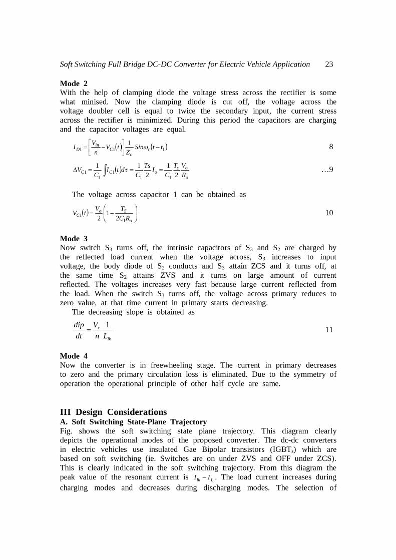
Mode 2 With the help of clamping diode the voltage stress across the rectifier is some what minised. Now the clamping diode is cut off, the voltage across the voltage doubler cell is equal to twice the secondary input, the current stress across the rectifier is minimized. During this period the capacitors are charging and the capacitor voltages are equal.
1111 ttSin
ZtV
nVI r
oC
inD
8
o
osoCC R
VTC
ITsC
dtIC
V2
12
11
111
11
…9
The voltage across capacitor 1 can be obtained as
o
SoC RC
TVtV1
1 21
2 10
Mode 3 Now switch S3 turns off, the intrinsic capacitors of S3 and S2 are charged by the reflected load current when the voltage across, S3 increases to input voltage, the body diode of S2 conducts and S3 attain ZCS and it turns off, at the same time S2 attains ZVS and it turns on large amount of current reflected. The voltages increases very fast because large current reflected from the load. When the switch S3 turns off, the voltage across primary reduces to zero value, at that time current in primary starts decreasing. The decreasing slope is obtained as
lk
c
LnV
dtdip 1
11
Mode 4 Now the converter is in freewheeling stage. The current in primary decreases to zero and the primary circulation loss is eliminated. Due to the symmetry of operation the operational principle of other half cycle are same. III Design Considerations A. Soft Switching State-Plane Trajectory Fig. shows the soft switching state plane trajectory. This diagram clearly depicts the operational modes of the proposed converter. The dc-dc converters in electric vehicles use insulated Gae Bipolar transistors (IGBTs) which are based on soft switching (ie. Switches are on under ZVS and OFF under ZCS). This is clearly indicated in the soft switching trajectory. From this diagram the peak value of the resonant current is Llk II . The load current increases during charging modes and decreases during discharging modes. The selection of
24 V. Delbin Jelaja and Dr. M. Rajaram
resonant capacitor is one of the important factor for the proper operation of the circuit, because the resonant capacitor reduces the turn off loss and turn-off dv/dt of the device. A large size capacitor can reduce the turn-off loss and turn-off circuits at the device. The rate of change of voltage across the resonant capacitor is given by
CI
dtdV LC …12
Fig.4 Equivalent circuits. (a) Mode 0 (b) Mode 1 (c) Mode 2 (d) Mode 3 (e) Mode 4

Soft Switching Full Bridge DC-DC Converter for Electric Vehicle Application 25
Fig.5 Soft Switching State-Plane Trajectory
Fig.6 Soft switching control scheme
B. Selection of Resonant Frequency Resonant frequency is the main factor to reduce the current stresses of rectifier diodes and conduction losses. Which is decided by leakage inductance and rectifier capacitance. The resonance frequency should be lower than switching frequency sr ff …13
CLf
lkr
21
…14
-100 0 100 200 300 400
M3
M0
M1
M4
IL
ILK
ILK-IL
M2
Near zero voltage
Reso
nant
Indu
ctor C
urre
nt (A
)
Resonant Capacitor Voltage
-20
0
60
20
40
80
Soft Switching Control scheme
PI
Main Pulse
Timing
Delay
IL*
IL
+
-
ie
PWM
Taux
Td
26 V. Delbin Jelaja and Dr. M. Rajaram
Leakage inductance is not adjustable without an additional leakage inductance we can select the rectifier. Capacitance, using the equation
2
22
2
218
r
s
lk ff
FsLnCC
… 15
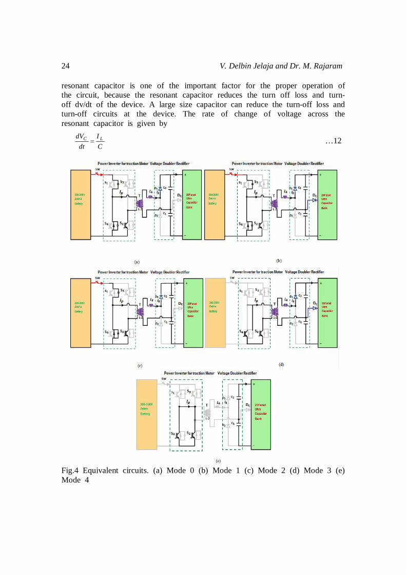
C. Selection of Ultra Capacitor The ultra capacitor system installed in an electric vehicle uses a high specific power brushless dc motor with a nominal power of 32kw and has a peak power of 53 kw. The ultra capacitor voltage is controlled through the variables such as vehicle speed and the state-of-charge of the battery. Fig. shows the ultra capacitor charge curve. This curve is plotted according to the time needed by the control to store the right amount of energy into the ultra capacitor bank. The amount of energy stored in the ultra capacitor is according to the car speed and battery state-of-charge. Suppose if the battery is fully charge only small amount of energy stored in the ultra capacitor bank. From this diagram the ultra capacitor level of energy (or) charge is calculated through electric vehicle speed (ie. car speed) and the battery state of charge (battery % DOD). The higher the speed, lower the charge and the higher the battery state-of-charge, the lower the charge too. The shape of the kinetic energy curve is estimated through the of vehicle is proportional to square of speed and the time the control takes to reach the desired ultra capacitor charge. The capacitance value is selected usually according to the voltage ripple level, which is usually less than 1% of output voltage (V0). Hence the capacitance can be determined as
20
%1max0
o
s
VTDIC farad ultra capacitor bank
Fig.7 Ultra capacitor charge curve

Soft Switching Full Bridge DC-DC Converter for Electric Vehicle Application 27
D. Design of Leakage Inductance A high turns ratio result in higher leakage inductance that causes a severe voltage stress across the rectifier diodes and increases power loss. When n2>n1, current ripple of the leakage inductance will increase. Since a larger current ripple will result in larger core loss in the leakage inductance, a high turns ratio is not desirable. In this study we choose n=2
sripple
olk fi
VDnL
max2
21
…17
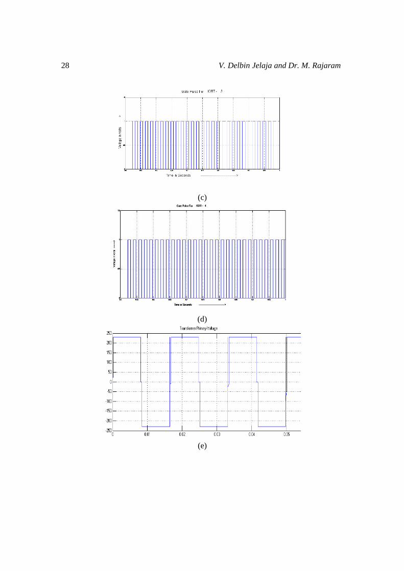
IV Simulation Results Fig shows the simulated results of the proposed converter. The requirements of high power in car is obtained with the help of voltage doubler circuit. This is depicted in Fig. Due to the resonance between leakage inductance of the transformer and voltage doubler capacitors, high voltage stress developed across the voltage doubler circuit. This is eliminated with the help of conduction of clamping diode. With the help of clamping diode and ultra capacitor bank we can obtain ripple free output voltage. That is also depicted in fig.
(a)
(b)
28 V. Delbin Jelaja and Dr. M. Rajaram
(c)
(d)
(e)

Soft Switching Full Bridge DC-DC Converter for Electric Vehicle Application 29
(f)
(g)
Fig.8 Experimental waveforms of the proposed converter (a-d) Gate Pulses (e) Transformer Primary Voltage(f) Transformer Secondary Voltage (g) output voltage of the proposed circuit
(a)
30 V. Delbin Jelaja and Dr. M. Rajaram
(b)
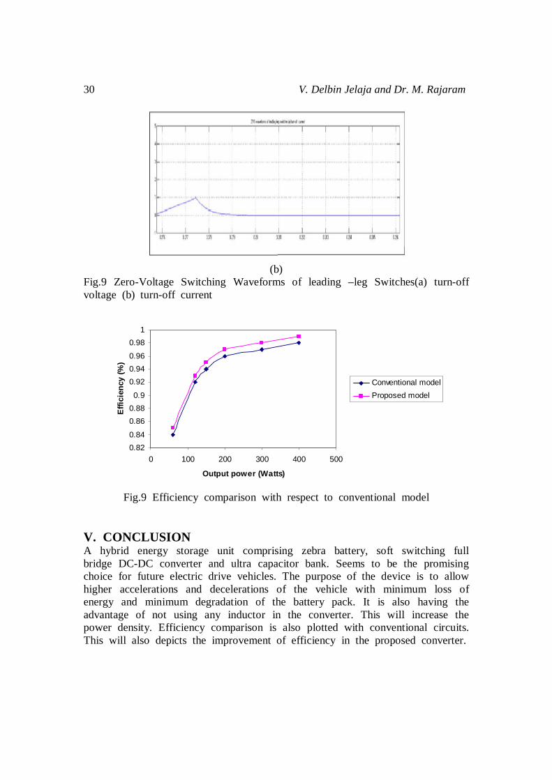
Fig.9 Zero-Voltage Switching Waveforms of leading –leg Switches(a) turn-off voltage (b) turn-off current
Fig.9 Efficiency comparison with respect to conventional model
V. CONCLUSION A hybrid energy storage unit comprising zebra battery, soft switching full bridge DC-DC converter and ultra capacitor bank. Seems to be the promising choice for future electric drive vehicles. The purpose of the device is to allow higher accelerations and decelerations of the vehicle with minimum loss of energy and minimum degradation of the battery pack. It is also having the advantage of not using any inductor in the converter. This will increase the power density. Efficiency comparison is also plotted with conventional circuits. This will also depicts the improvement of efficiency in the proposed converter.
0.820.84
0.860.880.9
0.920.940.96
0.981
0 100 200 300 400 500
Output power (Watts)
Effi
cien
cy (%
)
Conventional modelProposed model

Soft Switching Full Bridge DC-DC Converter for Electric Vehicle Application 31
REFERENCES
[1] Eung-Ho Kim and Bong-Hwan, Kwon, “Zero-voltage and zero-current-switching full-bridge converter with secondary resource,” IEEE Trans. Ind. Electron., vol.57, no.3, March 2010.
[2] J.G. Cho, J.A. Sabate, G.C. Hua and F.C Lee, “A Primary-side-assisted zero-voltage and zero-current-switching full bridge PWM converter for high power application.” IEEE Trans, Power Election, vol.2 no.4, pp.622-628, July 1996.
[3] C.C. Chan and Y.S. Wona, “Electric Vehicles Charge forward”, IEEE Power Energy Mag., vol.2, no.6, pp.24-33, Nov/Dec. 2004.
[4] S.K. Han, T.S. Kim, GW. Moon and M.J. Youn, “High efficiency active clamp forward converter for sustaining power module of plasma display panel”, IEEE Trans. Ind. Electron, vol. 55, no.4, pp.1874-1876, Apr.2008.
[5] K. Ruan and Y. Yam “A novel zero-voltage and zero current switching PWM full-bridge converter using two diodes in series with the lagging leg.” IEEE Trans. Ind. Electron. vol.48, no.4 pp.777-785, Aug. 2001.
[6] Woo. Jin Lee. Gun-Woo Moon, “A New Phose-shifted Full-bridge converter with voltage – Doubler – Type Rec for high efficiency PDP sustaining power module,” IEEE Trans. Ind. Electron. vol.55, no.6, June 2005.
[7] Morten and Michael A.E. Andersen, “High-efficiency Isolated Boost DC-DC Converter for High-Power Low-Voltage Fuel-Cell Applications,” IEEE Transactions on Ind. Electron. vol.57, no.2, February 2010.
[8] T.W. Ching, “Soft-switching Converters for Electric Vehicle Propulsion,” Journal of Asian Electric Vehicles, vol.5, no.2, Dec. 2007.
[9] A.F. Burke, “Batteries and ultracapacitors for electric, hybrid and fuel cell-vehicles”, Proc. IEEE, vol.95 no.4, pp.806-820, Apr. 2007.
[10] J.W. Dixon, M. Ortuzar, and E. Wiechmann, “Regenerative braking for an electric vehicle using ultracaacitors and a buck-boost converter”, in Proc. EVS18, Berlin, Germany, Oct. 2001, p.148.
[11] J.W. Dixon and M. Ortizar, “Ultracapacitors + DC-DC converters in regenerative braking system”, IEEE Aemsp. Electron, Syst. Mag. vol.17, no.8, pp.16-21, Aug. 2002.
[12] Xinke Wu, Junming Zhang, Xin Ye and Zhaoming Qian, “Analysis and Derivations for a Family ZVS Converter Based on a New Active Clamp ZVS Cell,” IEEE Trans. On Ind. Electron. vol.55, no.2, Feb.2008.
[13] H. Tao, A. Kotsopoulous, J.L. Durate and M.A.M. Hendrix, “Transformer-coupled multiport ZVS bidirectional dc-dc converter with wide input range,” IEEE Trans. Power Electron, vol.23, no.2, pp.771-781, Mar.2008.
[14] H.K. Yoon, S.K. Han. J.S. Park, G.W. Moon and M.J. Youn, “Zerovoltage switching two-transformer full-bridge converter with lossless diode-clamp rectifier for PDP sustain power module,” IEEE Trans. Power Electron, vol.21, no.5, pp.1243-1252, Sep.2006.
32 V. Delbin Jelaja and Dr. M. Rajaram
[15] L.Shiguo, Q. Weihong, W. Wenkai and I. Batarseh, “Flyboost power factor correction cell and a new family of single-stage AC/DC converters”, IEEE Trans. Power Electron. Vol.20, no.1, pp.25-34, Jan. 2005.
Authors’ information
V. Delbin Jelaja received his B.E degree in Electrical and Electronics Engineering from C.S.I Institute of Technology, Thovalai, Tamil Nadu India, in 2003 and thereafter, she did her M.E. degree in Power Electronics and Drives from Government Engineering College, Tirunelveli, Tamil Nadu, India in the year 2009. She is presently a research Scholar at Anna University Tirunelveli. Her area of interest is Electrical Engineering, Power Electronics, which includes soft switching in electric vehicles and high power Applications.
Dr. M. Rajaram, Vice Chancellor Anna University of Technology, Tirunelveli, Tamil Nadu, India. He completed his B.E. Degree (Electrical and Electronics Engineering) at Alagappa Chettiar College of Engineering and Technology, Karaikudi in 1981, M.E. Degree (Power Systems) at Government College of Technology, Coimbatore, in 1988 and Ph.D (Control Systems) at PSG College of Technology, Coimbatore in 1994. He has successfully supervised 11 Ph.D and M.S (by Research) Scholars who are awarded with the Doctoral Degree and 10 candidates are pursuing Ph.D under his guideship at present. To his record he has published his Research findings in 75 International Journal/National Journals, 61 International Conferences and 53 National Conferences. He has also authored 6 Text Books, which the Engineering students find informative and useful. He is a life member of ISTE and MIE and an AICTE Expert member and the Chairman in granting affiliation to Engineering Colleges and Polytechnics.