softer handover schemes for high altitude platform station ... · softer handover schemes for high...
TRANSCRIPT

Softer Handover Schemes for High Altitude Platform Station (HAPS) UMTS
Woo Lip Lim, Yu Chiann Foo and Rahim Tafazolli Mobile Communications Research Group. Centre for Communication Systems Research. University of Surrey. Guildford. Surrey GU2 7XH. UK
Abstract: An important property of high altitude platform station (HAPS) Universal Mobile Telecommunications Systems (UMTS) is that unlike terrestrial tower based systems. interference is dependent on the antenna characteristics of HAPS rather than the terrain features (i.e., shadowing) in the service area. In this paper. we exploit this unique HAPS property to propose simple and effective adaptive softer handover schemes for HAPS UMTS. Simulation results obtained show that our proposed handover schemes provide improved system performance as compared to the existing conventional non-adaptive softer handover scheme proposed for terrestrial UMTS.
Key words: HAPS, UMTS. soft/softer handover
1. INTRODUCTION
Soft/softer handover are used in code division mUltiple access (CDMA) systems due to their various advantages over hard handover. When considering handover in a single platform HAPS CDMA system, we note that in concept, the HAPS geometry is similar to a very tall terrestrial tower projecting hundreds of sectorised cells. The handover between cells of a HAPS CDMA system is thus similar to the handover between sectors of a terrestrial tower based CDMA system. Hence. the handover process is faster and softer because a single timer can be used to synchronize all cells [1]. In this paper. we use the term softer handover (SHO) to refer to handover between cells of a single platform HAPS CDMA system.
When designing SHO schemes for HAPS UMTS, we should note that an important unique characteristic of HAPS UMTS is that all base station (BS) transmit
©
The original version of this chapter was revised: The copyright line was incorrect. This has beencorrected. The Erratum to this chapter is available at DOI: 10.1007/978-0-387-35618-1_37
C. G. Omidyar (ed.), Mobile and Wireless CommunicationsIFIP International Federation for Information Processing 2003©
The original version of this chapter was revised: The copyright line was incorrect. This has beencorrected. The Erratum to this chapter is available at DOI: 10.1007/978-0-387-35618-1_37
C. G. Omidyar (ed.), Mobile and Wireless CommunicationsIFIP International Federation for Information Processing 2003
124 Woo Lip Lim, Yu Chiann Foo and Rahim TaJazolli
antenna beams essentially originate from the same phased array antenna onboard the platform. As the altitude of the HAPS is much larger than the dimensions of the phased array antenna, the wanted and interfering signals traverse almost the same path and hence undergo similar path loss and shadowing. Therefore, the received signal-ta-interference ratios (SIRs) of the mobiles in HAPS UMTS are dependent on the antenna radiation pattern rather than the channel characteristics (path loss and shadowing) [1],[2].
In wideband CDMA (WCDMA) systems, a mobile continuously tracks the received energy per chip to interference power density ratio (EJ1o) of all the downlink common pilot channels (CPICHs) from the BSs in the service area and report this information to its serving BS. For HAPS UMTS, due to the collocation of BS antennas, the CPICH signals transmitted by the BSs to the mobile experience the same path loss and shadowing. Thus, if we assume that fast fading can be averaged out due to its short correlation length, then, the differences between the received EJ10 values from the mobile's serving BS and the neighbouring BS are basically the differences in antenna gains between the BSs. These antenna gain differences are deterministic and can be utilised to implement simple and effective adaptive SHO schemes.
In this paper, two adaptive SHO schemes for HAPS UMTS are formulated based on the unique HAPS interference property. The performances of the proposed adaptive SHO schemes are evaluated via simulation in terms of quality of service and resource utilisation and compared to the corresponding performances of the conventional non-adaptive SHO scheme (NADS) discussed in [3].
2. DESIGN STRATEGIES FOR HAPS UMTS SOFTER HANDOVER SCHEMES
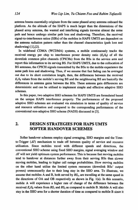
Softer handover schemes employ signal averaging, SHO margins and the Timeto-Trigger (Lin mechanism to trade off between quality of service and resource utilisation. Since mobiles travel with different speeds and directions, the conventional SHO scheme using fixed SHO margins, signal averaging window and LiT will not yield optimum system performance. This is because fast moving mobiles tend to handover at distances further away from their serving BSs than slower moving mobiles, leading to higher call outage probabilities. Slow moving mobiles on the other hand utilise the limited system resources (downlink BSs' output powers) unnecessarily due to their long stay in the SHO area. To illustrate, we assume that mobiles A and B, both served by BSh are travelling at the same speed in the directions of OA and OB respectively as shown in Fig. 1(a). In this scenario, mobile A will experience a higher rate of change of the difference between the received EJlo values from BS) and BS2 as compared to mobile B. Mobile A will also stay in the SHO area for a shorter duration of time as compared to mobile B since it

Softer Handover Schemes for High Altitude Platform Station (HAPS) 125 UMTS
crosses a smaller SHO area. Hence, if mobile A does not initiate the SHO process early enough, it will be more susceptible to call outage and hence call dropping as compared to mobile B. On the other hand, if mobile B initiates its SHO process too early, it will utilise the limited power resources unnecessarily.
Due to the unique characteristics in HAPS UMTS, the rate of change of the difference between the received EJlo from a mobile's serving BS and the strongest received EJlo from its neighbouring BSs (ROC.dpl/o,) can provide reliable information on a mobile's relative speed and travelling direction for the design of adaptive handover schemes since ROC.dpi/ot is only influenced by the BSs' antenna radiation pattern rather than the propagation environment. If the mobile's SHO add margin (8...t.t) and drop margin (4m,p)1 can be dynamically adjusted based on the information on ROC.dpilolt a better system performance can be achieved as compared to the conventional fixed threshold non-adaptive SHO scheme. Note that this method is not suitable for terrestrial tower based UMTS SHO as CPICH signals transmitted by different BSs to a mobile experience different levels of shadowing and path loss. Hence, tracking the ROC.dpilot will not provide an accurate and reliable indication of the mobiles' travelling speeds and directions in this case.
m
i 0' I! -10 / --. BS2 i 0(/2
i .., ·15
g; " . 20 / Travelling
BS / direction OA 1 BSz
o Q5 1 Distance Ikm) region
(a) (b)
Figure lea). HAPS UMTS handover scenario for mobiles travelling in different directions. (b). The intersection of the antenna radiation patterns of BS I and BS2 in OA direction.
a) EstabUshing the maximum and minimum ROC.dpiloI (ROC.dpIlot.1fIIIJt and ROC.dpIlot.min): A mobile travelling with the fastest speed in the direction OA and a mobile travelling with the slowest speed in direction OB in the service area will experience the maximum ROC.dpUotand the minimum ROC.dpUot respectively. Since the differences between the received EJlo values from the mobile's serving BS and the neighbouring BSs are basically the differences in antenna gains between the BSs, we can establish ROC.dpllot,mmc and ROC.dpl/ot.mtn of the system approximately using the HAPS antenna radiation pattern specified in (1)
assuming that the maximum and minimum mobile speeds in the service area are
I The definitions of &..!d and in [3] are used in this paper.

126 Woo Lip Lim, Yu Chiann Foo and Rahim TaJazolli
known. As shown in Fig. l(b), ROC4pilol.max = ILlpilol,• - LlpilolaVL1t where Llpilol,• and Llpilola are the differences between the normalised antenna gain levels in dB at the angles under which the fastest moving mobile is seen from the boresights of BS.'s and BS2'S antennas at time II and 12 respectively. L1t is the difference between 12 and 11 which is equal to the simulation time step. ROC4pilol.min can be obtained with the same approach using the slowest moving mobile travelling in direction OB.
b) Softer handover margin variation factor (o_ROC4pi/ot): Depending on the ROC4pilol the mobile experiences, a handover margin variation factor is added to the fixed handover margins to obtain the adaptive handover margins for the mobile. The SHO margin variation factor (O_ROC4pilol) for mobile i is:
1 ROC' -ROC . J o ROC'. = 6pilol 6pilol.1DID +0 ROC. . - 6pilol ROC . _ ROC . - 6p.IoI.1D1D
6p.IoI.max 6pilol.1DID
(1)
where P = 0 _ ROC bpilol.max - 15 _ ROC bpilol.min •
t5_ROC4pilol.max and t5_ROC4pilol.mln are the maximum and minimum SHO margin variation factors corresponding to ROC4pilol.max and ROC4pilol.mln respectively. O_ROC4pilol.max and t5..flOC4pilol.min are design parameters and the relationship between O_ROC4pilol and ROC4pilOI is shown in Fig. 2.
(LROC4pilol
o '-i--i----7"''-------r---... ROC4pilol
_
Figure 2. Softer handover margin variation factor vs. ROC4pilol'
c) Proposed adaptive softer handover schemes: Two adaptive schemes for HAPS UMTS are proposed in this paper. For the first adaptive scheme (ADSI), only the add margin is adaptable. A mobile with a larger ROC4pilOI will have a higher add margin as compared to mobile having a smaller ROC4pilol' The drop margin remains unchanged regardless of the values of ROC4pIlOl' Hence, for ADSI, the add and drop margins for mobile i can be written as:
t5:w".adopl = I5D1ld +15
= I5drop
(2)
(3)
where Oadd and I5t1rop are the add and drop margins used for the conventional nonadaptive SHO scheme as explained in [3]. For the second adaptive scheme (ADS2). both add and drop margins are adaptable and each mobile is assigned

Softer Handover Schemes for High Altitude Platform Station (HAPS) 127 UMTS
with individual add and drop margins according to its ROC""ilot. ADS2 ensures that a mobile having a larger ROC""ilot has a higher add margin and a lower drop margin as compared to a mobile having smaller ROC""ilot. The add and drop margins of ADS2 for mobile i are:
3. SIMULATION MODEL
(4)
(5)
We evaluate and compare the performances of ADSI, ADS2 and NADS under the following simulation conditions: a) HAPS system model: A HAPS carrying a WCDMA communications payload
and a multi-beam phased array antenna with beam/gain shaping capability is positioned at an altitude of 22 km in the stratosphere. It projects spot beams on the ground within the service area in a pattern similar to that created by a traditional cellular system to provide mobile communications services. Any residual pointing error due to the movement of the HAPS is assumed to be compensated by appropriate station keeping mechanisms or by steering the beams electronically [1]. The antenna radiation pattern used for cell projection has a sharp roll off of 60 dB/decade and conforms to the specifications proposed in [1]. The gain at cell boundaries is taken to be -13 dB with respect to the maximum main lobe gain (Gm).
b) Cell model: The simulation area consists of 19 cells located near the nadir that are approximated to be equally sized and circular in shape. With Gm = 36.7 dB, the cells projected on the ground have a radius of 1 km. The BSs are assumed to transmit only the CPICH and traffic channels. The transmit power for the CPICH is fixed at 33 dBm. The BS maximum output power is set at 42 dBm and the channel power limit is set at 30 dBm.
c) Traffic model: 32 kbps real time speech service is considered. Calls are generated according to a Poisson process with a mean call duration of 120 s. The speech service is modelled as an on-off model, with an activity factor of 0.5.
d) Mobility model: A newly generated call is assigned a uniformly distributed random location in the simulation area. Each mobile arriving to the system chooses the BS that provides the best link gain as its serving BS. The initial speed of a new user is generated by the uniform distribution U{50 km/h, 120 kmIh] and is assumed to remain unchanged throughout the call. The initial direction of a new user is generated by the uniform distribution U{00, 360°]. A mobile will travel an average distance of 2 km before changing its travelling

128 Woo Lip Lim, Yu Chiann Foo and Rahim TaJazolli
direction. The new direction is generated by a uniform distribution U[ -45°, 45°] with reference to the old direction.
e) Power control model: Centralised transmit power based call admission control is implemented, where calls are only allowed to enter the network provided that in maintaining the Ei/1o requirement, i.e. (Ei/lo),hreslrold of the new and existing calls, there is a non-negative power vector that accommodates the new mobile, and that the output powers of all BSs in the service area do not exceed their respective limits [4]. Furthermore, each forward link channel output power should not exceed an allowable limit. Otherwise, the call is blocked. Similar conditions are applied when adding a new BS to the mobile's active set (SHO mode). The SHO request will be denied if the above conditions are not met and mobiles will continue to try to execute the SHO process in the subsequent time step as long as the mobiles' add margins meet the SHO criteria. When a mobile is in SHO mode, we assume that all the BSs in the mobile's active set will transmit approximately equal amounts of power to the mobile. Fast fading is assumed to be averaged out due to its short correlation length and is not considered in our evaluation. M received samples of Ec!lo are averaged over a rectangular window before being compared with the SHO margins. Due to link variations caused by the mobility of the mobiles and/or varying channel and traffic conditions, even if no new mobiles are admitted, a feasible power vector might not be found at a particular instant. In this case, a simple step-wise removal algorithm is used to identify one by one the mobiles having the worst link gain conditions to be outaged (i.e., have their downlink traffic channels switched oft) until the required Ei/1o value is achieved in the remaining links [4]. A mobile that is in outage continuously for 1 s will be dropped.
t) Simulation parameters: The simulation parameters are summarized in Table 1.
Tabe 1m atlOn parameters l 1 IS' ul .
Parameter Value Patameter Value
Radio access WCDMA Chip rate 3.84 Mcps
Speech service bit rate 32 kbps (E"tlO)llrabdd 7dB
Mobile speed 50-120 kmIh Active set size 2
M (averaging number) 8 Max. BS output power 42dBm
i1T (adding. dropping 2.5 s Max. traffic channel 30dBm
and replacing a link) output power
Simulation time step 0.5 s CPICH transmit power 33dBm
4,., 2dB &"", 5 dB
.s ROCdpU«, .... 1 dB Ii -1 dB
g) Performance measures: The performance indicators used to evaluate the SHO schemes are:
I. Quality of service
New call blocking probability (Pb): The probability that a new user is denied access to the network by the call admission control mechanism.

Softer Handover Schemes for High Altitude Platform Station (HAPS) 129 UMTS
Call dropping rate (P d): The rate at which ongoing calls are dropped from the network due to the calls being outaged continuously for more than I s.
2. Resource utilisation Mean active set number: The average number of base stations in a mobile's active set throughout its call duration. Active set update rate: The average number of updates (add, drop or link replacement) in a mobile's active set per second.
4. RESULTS AND DISCUSSION
The antenna gains evaluated between 0.6 km and I km (where SHO is normally initiated and executed) is used to determine ROCiJpi/ot,max and ROCiJpi/ot,min' Any ROCiJpiiot values that are larger than ROCiJpi/ot,max or smaller than ROCiJpi/ot,min are fixed at ROCiJpi/ot,max and ROCiJpi/ot,min respectively. The performances of ADSI, ADS2 and NADS are evaluated using the HAPS system level simulator and the results are shown in Fig. 3.
Among the three schemes, NADS gives the worst quality of service. This is because NADS adds BSs to the fast speed mobiles' active sets later than the adaptive schemes. Since fast speed mobiles move towards the cell edge where interference is most severe very quickly, if these mobiles are not in SHO mode, BSs will need to transmit higher powers to these mobiles in order to maintain their received E,/Io requirement. This will result in the system being unable to meet the power requirements, with traffic channels' and BSs' output powers reaching their respective limits. Furthermore, since NADS allows slow speed mobiles to add an additional BS to their active sets earlier than the adaptive schemes, the mean active set number for NADS is higher than the mean active set numbers for the adaptive schemes. This means that NADS will utilise more power resources leading to new calls being blocked and existing calls being removed from the network. In contrast, the proposed adaptive SHO schemes allow mobiles travelling at higher speeds to initiate the SHO earlier and mobiles travelling at slower speeds to initiate the SHO process later so that after the duration of L1T, all the mobiles with different travelling speeds and directions will be able to add the second BS to their respective active sets at about the same distance away from the cell centre. Hence, a more uniform quality of service for all mobiles can be achieved with less resource utilisation.
Comparing the two adaptive schemes, ADS2 has a slightly higher mean active set number than ADS 1. This is likely due to ADS2 dropping the weaker BSs in the slow speed mobiles' active sets later than ADS1. Since slow speed mobiles will not be able to move out of outage conditions as quickly as the high speed mobiles after the weaker BSs are being removed from their active sets, it might be more beneficial to drop the weaker BSs in the slow speed mobiles' active sets slightly later. This will ensure that the slow speed mobiles can have good link quality with their serving BSs once the weaker BSs are removed from their active sets and prevent the system from reaching the traffic channels' and BSs' output power limits. As a result, ADS2 is able to achieve better Pb and Pd as compared to ADSI as shown in Fig. 3, We also

130 Woo Lip Lim, Yu Chiann Foo and Rahim TaJazolli
note that ADS! and ADS2 do not cause any increases in the active set update rates as compared to NADS.
In conclusion, the proposed two adaptive SHO schemes for HAPS UMTS outperform the conventional non-adaptive SHO scheme in both quality of service and resource utilisation. ADS2 is able to achieve a much better quality of service as compared to ADS!. However, ADS2 utilises slightly more resources and is also more complex to implement as compared to ADS! since both add and drop margins are dynamically adapted to the mobiles' ROCI1pi/ot. These proposed adaptive SHO schemes are simple to implement since information on the received Eel10 values from the mobile's serving BS and the neighbouring BSs are readily available.
0.1
:?!'O.06 :8 .s 0.06 6:
i O.04
05 0.02
14 16 18 20 Traffic Load (Er1angs)
1.225
J! 1.22
i 1.21
22
CI
0.01
15 30.005
14 16 18 20 Traffic Load (Erlangs)
22
.",
-;; 0.044 Oil It: .!! 0.0435
i ::. 004 ;g . 10.0425
0.042,L.4---:16-:----'6---:20::-:----l22
Traffic Load (Erlangs) Traffic Load (Erlangs)
Figure 3. Blocking probability, call dropping rate, mean active set number and active set update rate over different traffic loading.
REFERENCES
[1] lTU, "Revised technical and operational parameters for typical IMT-20oo terrestrial systems using high altitude platform stations and CDMA radio transmission technologies," ITU Document 8-1/307-E, March 1999.
[2] Y.C. Foo, W.L. Lim, R. Tafazolli and L. Barclay, "Other-cell interference and reverse link capacity of High Altitude Platform Station (HAPS) COMA system," Electron. Lett., vol. 36, pp. 1881-1882, Oct. 2000.
[3] W.L. Lim, Y.C. Foo, R. Tafazolli and B.G. Evans, "Softer handover performance of high altitude platform station W-CDMA system," in Proc. of WPMC'Ol, Aalborg, Denmark, pp. 99 -104, Sep. 2001.
[4] Y.C. Foo, W.L. Lim and R. Tafazolli, "Centralized downlink call admission control for high altitude platform station UMTS with onboard power resource sharing," accepted for IEEE VTC Fall 2002, Vancouver, Canada, Sep. 2002.