software-defined edge cloud framework for resilient...
TRANSCRIPT

Research ArticleSoftware-Defined Edge Cloud Framework for ResilientMultitenant Applications
Kaikai Liu ,1 Nagthej Manangi Ravindrarao ,1 Abhishek Gurudutt ,2
Tejeshwar Kamaal ,2 Chinmayi Divakara ,2 and Praveen Prabhakaran 2
1The Department of Computer Engineering, San Jose State University (SJSU), San Jose, CA, USA2San Jose State University, USA
Correspondence should be addressed to Kaikai Liu; [email protected]
Received 23 June 2018; Accepted 8 November 2018; Published 1 January 2019
Academic Editor: Yu Chen
Copyright © 2019 Kaikai Liu et al. This is an open access article distributed under the Creative Commons Attribution License,which permits unrestricted use, distribution, and reproduction in any medium, provided the original work is properly cited.
Edge application’s distributed nature presents significant challenges for developers in orchestrating and managing the multitenantapplications. In this paper, we propose a practical edge cloud software framework for deploying multitenant distributed smartapplications. Here we exploit commodity, a low cost embedded board to form distributed edge clusters. The cluster of geo-distributed and wireless edge nodes not only power multitenant IoT applications that are closer to the data source and the user, butalso enable developers to remotely deploy and orchestrate application containers over the cloud. Specifically, we propose building asoftware platform to manage the distributed edge nodes along with support services to deploy and launch isolated and multitenantuser applications through a lightweight container. In particular, we propose an architectural solution to improve the resilience ofedge cloud services through peer collaborated service migration when the failures happen or when resources are overburdened.We focus on giving the developers a single point control of the infrastructure over the intermittent and lossy wide area networks(WANs) and enabling the remote deployment of multitenant applications.
1. Introduction
In recent decades, cloud computing has emerged in theinformation and communication world, providing varioustypes of services, storage, computing, and networking. Data isaggregated to cloud data stores for intelligent processing withunlimited resources; applications are delivered and updatedto data centers in real time; and computing infrastructureand resources can be shared with other applications on thego without interference. However, the main cloud is hostedin core data centers, which are sometimes far from the enduser. This may introduce a considerable delay for end users’applications, thus preventing the deployment of servicesthat are sensitive to latency, for example, cyber-physical-systems (CPS), smart cities applications, securitymonitoring,connected vehicles for Intelligent Transport Systems (ITS), orInternet ofThings (IoT) [1–3]. Low latency analytics and real-time response are especially important for cyber-physical-system (CPS) applications. The dominant approach ofaggregating all data to the data center stresses communication
links, thus inflating the timeliness of analytics. Moving muchof the processing to the locations where the event is hap-pening facilitates real-time response and low communicationoverhead. To address the problem of the long latency, cloudservices should be moved more proximally to the edge ofmobile network [4, 5]. There is need for a system that canproactively provide computing services for theseCPS and IoTdevices as needed.
Mobile edge computing (MEC) can be understood as aspecific case of mobile cloud computing (MCC), where thecomputing/storage resources are supposed to be in proximityto the user equipment (UE) [6, 7]. Hence, MEC can offersignificantly lower latencies and jitter when compared tothe MCC. Consequently, mobile edge computing may beconsidered one of the key enablers of Internet ofThings (IoT)as it offers (1) low latency combined with location awarenessdue to proximity of the computing devices to the edge ofthe network, (2) widespread geographical distribution whencompared to the data center; (3) interconnection of a verylarge number of nodes (e.g., wireless sensors); and (4) support
HindawiWireless Communications and Mobile ComputingVolume 2019, Article ID 3947286, 17 pageshttps://doi.org/10.1155/2019/3947286
2 Wireless Communications and Mobile Computing
of streaming and real-time applications [8]. Many organi-zations contribute to the concept of edge computing underdifferent initiatives, for example, the mobile edge computing(MEC) initiative by ETSI, Fog computing byCisco [9, 10], andcloudlet by Carnegie Mellon University [11, 12]. Nevertheless,MEC also imposes huge additional challenges, including (1)multitenant support [13]; (2) automatic orchestration; and (3)resilience and availability.
(1) Multitenant Support. The support for multiple cus-tomers to use a single instance of the software infrastructurehas been evolving from decades. We are leveraging theconceptual model of multitenant software architecture whichis to run a single instance of software on a server andserving multiple tenants. The group of end customers/clientsrequiring the services of this edge cloud framework is calleda tenant. These tenants share common access policies andhave dedicated privileges for accessing our edge framework.Each tenant is provided with a shared instance includingdata storage, configuration and user management, and otherpreferences. With this type of software architecture for IoTmodels, we are utilizing data aggregation benefits throughacquiring data from centralized storage instead of differentdatabase schemas, and the cost to implement multitenancycan also be minimized as a single instance is being used bymany customers which substitutes the invested amount formemory and processing overhead.
IoT and CPS application developers need an infras-tructure to support multitenant applications. Several of theexisting edge computing platforms support either a single-user application, an application specific cloudlet, or a singleservice-oriented cloudlet. To operate, maintain, and securethis edge cloud network, researchers must grapple withmultiple vendor-specific computing and sensing modulesto implement complex high-level management policies. Forexample, multiple companies are applying to install smartsensors in street lights. However, this can be rather slowand labor-intensive due to the administrative process ofdetermining which companies to offer permission. After thenodes are installed, they become the private property of thevendor. That said, it is difficult for new applications andservices to utilize this existing platform. Similar to cloudcomputing, the computing and sensing modules availablein edge nodes should be virtualized as a resource pool thatintegrates a cluster of applications to provide agility, respon-siveness, and less overhead than traditional hypervisor-basedvirtualization. Despite many previous proposals to make theVMs in data centers easier to manage, many approaches arenot fit for this edge cloud scenario or only amount to stop-gapsolutions because of the underlying highly distributed andlow-complex infrastructure.
(2) Automatic Orchestration. Application developersneed a hassle free way to deploy, test, and update theirmultitenant applications to remote nodes in a seamlessmanner and ensure the services are running smoothly withhigh availability. However, at the present time applicationsspanning cloud and edge are still provisioned manually. Dif-ferent from current cloud infrastructure in data centers, city-wide infrastructure contains thousands of geo-distributedwireless edge nodes deployed in residential areas, streets,
or parks. Enabling automatic application orchestration ineach edge node with high reliability is unachievable usingexisting solutions. To provide a robust environment wheredevelopers can remotely deploy and debug their applicationsin the cloud of edge nodes, the orchestration layer with theremote management dashboard is a must-have to enableautomation.
(3) Resilience and Availability. Due to the limitedcomputing and storage resources of the edge node, thefully distributed deployment, and the unpredictable servicerequests, it is hard for developers to ensure resilient appli-cation and services. Different from data center networkswhere cable/fiber connections are more reliable, edge cloudinfrastructure involves distributed heterogeneous gatewaysand unreliable wireless links. As unpredictable disasters andattacks increase, we need a resilient network design forthe edge cloud infrastructure that avoids any single pointof failure and keeps all the edge nodes connected to vitalservices. The deployed smart application should be able toeasily reroute via the software-defined infrastructure whileat the same time collaborating with nearby peers to achieveimproved disaster preparedness and response. The adaptivemonitoring software will determine when the hardware islikely to fail, when resources will exceed capacity, or whereattacks are happening, and finally, deliver the agility andflexibility needed to support multitenant smart applications.
Abstracting the hardware edge node to multitenantapplications can help improve device utilization, lower thesystem deployment cost, and accelerate the real world testingand deployment of new applications. However, to supportmultitenant isolated applications on an edge device node, anedge cloud software platform with the following capabilitiesis needed: (1) providingmultiple virtual computing resourcesto multiple applications; (2) supporting application isolationfor securemultitenancy; (3) creating a versatile runtime envi-ronment that supports a variety of technologies and devicesfromdifferent vendors; and (4) providing a remote dashboardof the edge cloud that enables third-party application ven-dors/users to launch and manage applications remotely. Toenable remote orchestration of multitenant IoT applications,numerous attempts have beenmade to extend the flexibility ofthe cloud into distributedmini data centers such as cloudlets.Stack4Things extends the OpenStack for IoT applications[14] while Openstack++ provides multitenancy through VMbased computing resources [15]. This solution of providinghypervisor-based computing resource to establish multite-nancy adds a redundant software abstraction layer, thus creat-ing a nondeterministic application. However, the integrationof various server-oriented technologies makes the systemheavy and expensive to use in IoT applications. Moreover,these solutions do not emphasize the continuity of servicesand high availability. Edge nodes are commodity hardwarenodes distributed in the harsh environments and runningcomputation for applications with unpredictable demand.There lacks a system to provide continuous multitenancyinfrastructure services for application vendors when a devicein the cluster or an edge node is overburdened.
In this paper, we propose an architecture for a Platform-as-a-Service (PaaS) to automate multi-tenant IoT and CPS
Wireless Communications and Mobile Computing 3
HTTP Request/Response
HTTP Request/Response
DB
WebServer
Application file to control
Sensor in remote location/
Container Control CommandsLogs from end node
Application file to control
Sensor in remote location/
Container Control Commands
Logs from end node
RequestHandler
WAMPServer
Mes
sagi
ng T
unne
l
Messaging TunnelWAMPClient
Docker Management
Container
Sensor Control
DockerHub
Start Container!!Stop Container!!
RemoveContainer!!
Upl
oad
Appl
icat
ion/
Con
tain
er C
ontro
lC
omm
ands
Logs
User 1 User 2
Fog ComputingNode 1
Fog ComputingNode 2Upload Application/
Container ControlCommands
Logs
SensorCamera
App 1 App2
Router
Router
Camera Deployed onstreet
Heat sensor deployed inforest
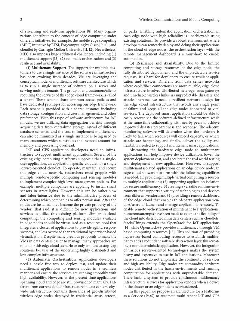
Figure 1: The architecture diagram of system implementation.
applications provisioning in an edge computing environ-ment. Based on our previous results [16], we propose a soft-ware framework to enable the envisioned edge cloud platformwith three key functionalities: (1) supporting multitenantisolated user applications via lightweight virtualization; (2)providing a cloud dashboard for remote programming andapplication management; and (3) featuring robust networkconnectivity agnostic to network mediums. The frameworkprovides computing resources through a lighter, more deter-ministic container-based virtualization (i.e., IaaS). The com-puting resource holds all the dependent libraries and runtimeenvironments required to run the isolated application (PaaS).The edge cloud provides a solution offering remote dynamicdiscovery that enables the user to control and manageapplications remotely through a web application dashboard.To ensure service availability and resilience, we proposesolutions to seamlessly migrate services amongst nearbyedge nodes via lightweight communication protocols whena failure happens or when the resources are overburdened.As a use case, the proposed PaaS was employed to provisionmultitenant stateless IoT applications that run on top of lowcomplexity edge devices, for example, Raspberry Pi, NVIDIAJETSON, and Beaglebone.
2. System Overview
2.1. SystemDesign. Cloud computing is a promising paradigmwith many inherent advantages, such as the easy and effi-cient provisioning of new applications and resources, not tomention scalability [17]. It encompasses Infrastructure-as-a-Service (IaaS), Platform-as-a-Service (PaaS), and Software-as-a-Service (SaaS). Application providers use platforms(offered as PaaS) to provision (i.e., develop, deploy, andmanage) applications. Edge environment is composed of
heterogeneous mobile and low-end devices. The computingcapabilities are not comparable to the state of the art serversat the data centers. Existing PaaSs (e.g., Cloud Foundryand Google Cloud Platform) do not enable the provisioningof applications with components spanning cloud and theedge node. Most IoT and CPS applications are manuallyprovisioned today.
We propose a PaaS for these remote edge nodes and orga-nize them as a pool of resources for IoT and CPS applicationswith collaboration mechanisms to provide high availabilityand fault tolerance for application developers. To meet theserequirements, we focus on two design directions for thisedge computing platform. The first is to build a scalableand lightweight execution environment that enables flexibleprovisioning of resources for multitenant applications over awide area network (WAN). The second is to provide usersa programmable system to manipulate their applicationsdeployed on remote resources and ensure resilience and zerodowntime via fault tolerant solutions.
2.2. Overview of System Implementation. (1) Cloud Dash-board.When many applications are deployed using the sameIoT infrastructure, resource isolation across different compo-nents and between applications is necessary. Container tech-nology is an ideal choice due to its lightweight virtualizationand small memory footprint [18]. Since all applications sharethe OS, restarting a container does not require the OS torestart. Docker’s union file system combines layers into asingle image, making it ideal for hosting applications in theedge computing platform.
As shown in Figure 1, the cloud dashboard contains threemajor parts: user interface, database, and messaging services.These three components are interfaced by the request handlermodule.The requests generated by users in the user interface

4 Wireless Communications and Mobile Computing
are queued by the handler module and then stored to thedatabase to maintain a copy.
User Interface. The user interface provides a user-friendly web application which allows the user to easilycreate, deploy, start, stop, and remove remote applications.The dashboard serves as the centralized interface for the usersto interact with their own applications. For example, userscan check the status of their application, control the settings,collect the results, and debug the software. The dashboardcan display the collected data as a graph, monitor the com-putational resources, aggregate the result files to download,and display the available end edge nodes. For example, anauthenticated user can login to the dashboard and accesshis/her edge node. A user can also deploy his/her applicationto the preferred edge node through this dashboard.
Messaging Service. Messaging services have becomean important portion of the Internet of Things. Messagingservices not only include communication between twonodes,but also provide security and reliability. The messaging ser-vice takes care of transmitting themessage to the desired nodethrough the public Internet for the services of device or endnode registration, heartbeat information, message transfer,and application deployment. Device or end node registrationwith the server is also a criterion for our project. Thecommunication between the end node and server, remoteconfigurations to register the end nodes to the server, andthe secure communication are fulfilled with the help of ourproposed messaging service.
We utilize the Web Application Messaging Protocol(WAMP), which is an open standard WebSocket protocol,to provide the application interface over the fusion link.Through the combination of the WAMP with the fusionlink, sensor devices without internet connection can bereached, which also provides resilient connection servicesrobust to the Internet loss. We support two types of logicconnection: remote procedure calls and publish-subscribemessaging services. WAMP is mainly used for distributed,multiclient (edge nodes in our use case scenario), andserver applications. Autobahn framework and Crossbar areused to host a server for message routing. Autobahn isan open-source implementation of WAMP and Websocket.Crossbar is a networking platformdesigned to handle routingfor distributed and micro-service applications. The serverand client are coupled via a publish & subscribe (PubSub)approach through a router to publish an “abstract” topic tothe subscribed client. After the transmission is complete, theserver and client are decoupled by the router (also namedbroker), which keeps track of subscriptions.When an “event”is published by a publisher to a topic, the broker looks up therecord to determine the list of subscribers and then forwardsthe information (the “event”) to those subscribers.
Database. The database will be used to save informationrelated to the user, container, the location of the storedresults, and so on.We utilize a relational database to establishthe relationship between different management entities. Toachieve modularity, the database is divided into five compo-nents, i.e., user, computation, image, device, and storage. Arelationship is established between the modular DB tablesto link the user to the resources allocated to him/her on
the edge cloud platform. The database access on the cloudis done through a database service which links the DB toother modules through REST APIs. This offers portabilityand provides language/platform independent interface whileoffering a loose coupling with other service modules.
(2) Edge Node:ContainerManagement. Containers pro-vide a complete software package required to run a user’sapplications on the edge node by abstracting the underlyingoperating system. There are different techniques to managethe containers deployed on a machine such as Swarm [18],Kubernetes, Fleet, and so on [19]. Swarm container manage-ment is effective and lightweight when compared to othertechniques. It converts all the Docker hosts into one singlevirtual host. All the nodes created on the edge device arecontrolled, scheduled, monitored, and cleared using swarmmanager. Swarm manager also helps us to keep a check onresource utilization.
In our system, containers are launched with applicationsrequested by each user. All dependent libraries to run theapplication inside a container are installed before executingan application. Every user can deploy a new container for eachapplication and obtain the results. Once the execution of anapplication is completed, containers are deleted automaticallyby the Docker daemon.
3. Cloud Orchestration Framework forthe Remote Edge Node
3.1. Resilient Network with High Mobility. Existing cloudsolutions require either a private network or fixed IP address,which is not achievable for the distributed edge nodes. Mostof the edge nodes are connected to the public Internetwithoutfixed IP and some of them even connect through IEEE 802.15-based sensor networks, for example, the 6LoWPAN network.We propose building a fusion link solution to manage thedistributed edge nodes through lightweight messaging ser-vices. We propose utilizing a resilient messaging tunnel tomanage the distributed edge nodes, making it agnostic tonetwork mediums as well as supporting dynamic access andmobility support. This messaging service will enable us tocontact any remote node based on ID instead of fixed IP.We propose an architectural solution to remotely access edgecloud management services through intermittent Internetconnections and close the connection to save power whennecessary. Specifically, we build a network overlay above theWAN and 6LoWPAN. When the edge node is not accessiblevia the WAN, our network overlay will automatically switchthe connection from WAN to the 6LoWPAN. Our networkoverlay also helps to bridge the WAN connection to the6LoWPAN network, which served as a gateway that seam-lessly bridge the Internet world (WAN side) to the sensorworld (6LoWPAN side).
Handling Registration and Heartbeat. Every end nodewhich connects to the server is registered with a unique ID.Each unique ID is part of the topic while subscribing. Whena user requests to perform actions on the end device, thisunique ID is used to publish the request to the desired endnode. The periodic heartbeat message is transmitted to theserver from all the registered end nodes to make sure the

Wireless Communications and Mobile Computing 5
end device is available for the user. The heartbeat messagecontains information about the device ID. The very firstheartbeat is considered for device registration. The heartbeatconsists of device ID, location, and architecture of the device,which are updated to the database upon registration.
3.2. Cloud Dashboard. In the cloud dashboard, user registra-tion is the first step, uponwhich the user can log in to the userdashboard to orchestrate the end nodes. Various commandssuch as start, stop, create, and remove a container, as well asupload and download a file from a virtual space on the endnode are provided for the user. The requests from the userare received through a REST API. The requests which areintended for the end device are filtered. The filtered requestsare then checked for validity, to make sure all the requiredfields exist in the request. With any field missing, an errormessage to the user is transmitted. With this validity checkon the server, the failure of command execution on the enddevice is reduced and also the response time to update theerror to the user is decreased. Once the validity check ispassed, URI is formed based on the device ID and the requestraised. Since device ID would be unique for all the registereddevices, the “event” is published to the specific device asintended by the user.
Create Container API. Lightweight virtual spaces areprovided to users to deploy and execute applications. Thesevirtual spaces can be created by the click of a button from auser dashboard. Each container is given a unique name byappending the username along with the requested containername.During the creation of a new container, if the requestedimage is not preinstalled on the device, then the image isfetched from theDocker hub and created. Any custom imagescan be uploaded to the Docker hub by the user requested topull when required.
Start, Stop, and Remove Container API. Each virtualspace can be orchestrated from the user dashboard. Somecommands provided to the user are to start, stop, andremove. Each of the commands is transferred to end throughthe server from the user dashboard. Upon receiving thecommand, the corresponding API is executed. A negativeresponse is transferred back if the API fails. If not, then apositive response is sent.
Device ID Generation. When the end node applicationis started, the device name and MAC address of the deviceare fetched. The same is concatenated in the form “devicename / MAC address.” With the help of both the devicename and MAC address, it is possible to keep each deviceID unique, thus helping to differentiate the message to bepublished according to the device selected by the user.
Location of Device.The location of the device is mappedduring deployment and stored in the cloud as one of thekey traits of the edge node. This helps to classify each devicebased on the location. Developers can make use of thisfeature to deploy their application to a specific location. Forexample, smart city-based applications utilize the location asthe service segment.
Architecture of the Device. The architecture of the endnode is fetched and updated during the device registration.We support multiple devices with Linux operating systems,
for example, ARMand x86CPU. Example device architectureincludes device name, CPU type, memory, and disk. Con-tainer compatibility is based on the architecture. Hence, bydetecting the architecture, suitable containers can be listedto the user for deployment. On successful login, a user canaccess his/her dashboard. In the dashboard, the user canfind a list of containers created by all the devices. The usercan also control the containers by clicking the containercontrol buttons and see the device information by selectingthe device.
4. Edge Node Virtualization
4.1. Edge Node. (1) Device Registration and Maintenance. Anedge node can be any embedded device such as BeagleboneBlack, Raspberry Pi, Jetson TX1, and so on. Edge node, uponbooting up registers to the server with a device name, trans-mits periodic heartbeats to indicate the node is alive. Oncethe device boots up, a registration message is transmitted tothe server.The registrationmessage consists of device ID.Thedevice ID is unique to each device. The device subscribes toall the “events” with a unique URI containing the device ID.After registering, the device sends a periodic heartbeat. Theheartbeat is a short commandmessage to the server to test theconnectivity. Once the device boots up, the device checks foran Internet connection and tries reconnecting to the Internet.Once the Internet connection is established, the device formsa device name, detects its location and architecture, andtransmits periodically to the server to indicate the end nodeis alive. The heartbeat stops when the device turns off. Whenthe server did not receive the heartbeat for a long periodof time, the cloud framework will inform users about theunavailability of the device, hence unregistering from the listfor usage.
Thenode also transmits device information and containerstatus periodically to the server. The device info containsthe device ID, device name, memory consumption, CPUusage, diskmemory available, operating systemon edge node,and kernel version. All this information is contained in theheartbeatmessage and updated to the server periodically.TheCPU information can be used to detect the available systemresources before deploying containers.
Docker engine is installed on the edge node, allowingthe users to deploy their application by creating contain-ers. Docker provides numerous amounts of packages fordevelopers to design and develop application programminginterfaces for creating, deleting, running applications, and soon. The edge node communicates with a WAMP agent toreceive the commands issued by users.The response from theedge node is sent back to notify the user about the actiontaken by the Docker. Every application creates a containerwhich is isolated from other containers running on the sameDocker engine. This isolation is provided by the Dockertechnology. Once the Docker engine is installed on the endnode, the Docker daemon runs on boot up of the end nodeand continues to run as long as the end node is not turned off.As soon as a command is issued from the user, the Dockerreceives a command from the WAMP agent and performsthe necessary action. The status of the container is updated

6 Wireless Communications and Mobile Computing
periodically.The statusmessage contains the container name,status, and device name to detect both the devicemaintainingthe container and the image name. Container status canbe redirected to inform the user about the status of eachcontainer. All status messages are updated to the databaseand will notify the user if some of the parameters exceed thespecified boundaries.
(2) Handle Remote Request and Deploy Application. Thesubscribed “event” of the edge node receives the requestfrom the server, containing information about the containercontrol. The received request is then parsed to the formatas required by the Docker API. During “create” request,each container is renamed according to the user’s demand.Container names received through the request are furtherformatted to fit in the form “username-containerName.” Bydoing so, each container created has a unique name. Oncethe container is created, a unique container ID returned bythe Docker API is tagged along with the container name formore clarity. The response returned by the Docker API istransmitted to the server to indicate the user and also thesame in a database.
The application file from the developer can be down-loaded from the cloud dashboard to the specific containersin the remote edge node when the user requests. The usercan upload their application file via.tar format and commandscript about running the application. The cloud dashboardwill handle all the requests and validate the files throughdefined policy. User requests, after validated on the server,are transmitted to the respective edge node. The receivedcommands contain the location of application file on theserver which is used for download. When the node receivesthe application file, it extracts the.tar file and runs the com-mand script to execute the application. This process makesit easy and flexible to deploy the application to the remoteedge node without being burdened by different run-timeenvironments and configurations during the deploymentprocess. Any applications, as long as they can be formatted asa.tar file and command script, can be deployed through ouredge computing dashboard.
5. Ensure Service Resilience viaContainer Migration
Cyber-physical systems are deployed in a variety of hostileenvironments that are subjected to changes such as hardwarefailures, extreme weather, natural disasters, terrorist attacks,and even cyber attacks.The quality of the underlying networkthat connects these edge nodes varies at different conditionswith high dynamics. Lossy network leads to loss of con-siderable resources and data by genuine users. A resilientand scalable infrastructure is needed to enable the properoperation of remote edge and IoT nodes in this type ofremote, hostile environment.
When physical edge nodes are down, we utilize a fail-over approach using the high-availability images to restorethe edge node operating system. However, it takes a longtime for this process to restore the whole operating system.We also monitor each container in the cloud dashboardby using heartbeat and restoring a container when it is
down. However, the data may be destroyed depending onthe timing of failures because restoration methods of failededge nodes and containers are independent. Moreover, withthe decrease in size and computational powers of edge nodes,a single node cannot handle the dynamic workload for IoTapplications. IoT applications provide sensing and actuatingapproaches for real-time events. However, demand for theevents is hard to predict. Different from data centers thatcan serve the dynamic demand via pool resources, the localresources available in one edge node are not sufficient forhigh application demand. An efficient mechanism to migrateservices amongst the edge nodes is neededwithout disturbingthe underlying sensor mesh when failure happens or theresources are overburdened. Service migrations betweenthe edge nodes are also important for mission critical IoToperations such as intelligent transport systems or connectedvehicles.
Therefore, we propose a fast and reliable restorationmethod with a uniform method for plural-type virtualresources. In ourmethod, the local framework in the primaryedge node predicts the node failure and insufficient resourcesand notifies the virtual resource arrangement scheduler, afterwhich a virtual resource arrangement scheduler queries thecloud for potential nearby edge nodes for collaboration. Itdetermines both the type of peer nodes required to migratethe container and application data from the primary node tothe peer node. The virtual resource arrangement scheduleralso buffers new sensor data and restores the applicationin the peer node for data processing without data loss. Weimplement the proposed method and show its effectivenessregarding peer collaboration through container migration.
5.1. Connections and Collaborations between Peers. Figure 2shows an overview of the container migration scenario.Considering intermittent WAN connections, the peer nodemany not be reached even given close physical distance. Toimprove connectivity resilience, we propose a network overlayover the WAN and low complexity 6LoWPAN technologiesfor peer connections. If the peer node is connectable via theWAN, the Message Queuing Telemetry Transport (MQTT)protocol will be used to initiate the container migrationprocess. If the WAN connection is lost, our network overlaywill automatically pick up the lost connection via 6LoWPANvia MQTT protocol. MQTT is a lightweight machine-to-machine protocol with very little implementation footprint-ing.We utilize the feature wherebyMQTT is available in bothWAN and 6LoWPAN. The MQTT broker functionalities areintegrated at the edge computing embedded platforms whichserve as a message exchange channel for container migration.
When a primary node wants to connect to the peer nodewith the broker, its makes a connection call first followed bya subscribe message. It has a variable list of topic(s) alongwith QoS value. The QoS value is defined as the level ofcollaborations provided by the peer node. We define threelevels of QoS values: (1) Level “0”: the peer node can providemessaging services and can help contact its own nearbypeers for collaboration, but the available resources are notsufficient to migrate the container; (2) Level “1”: persistentstorage is available to ensure container delivery, but the

Wireless Communications and Mobile Computing 7
Cloud
Edge Node (Master)
Tenant1
Docker Container
Tenant2
Docker Container
WAN
6LoWPAN
Tenant1
Docker Container
Tenant2
Docker Container
IoT&CPSApplication
IoT&CPSApplication
IoT&CPSApplication
IoT&CPSApplication
WiFi-based
Edge Node (Agent)
MQTT MQTT
Peer Connection (MQTT / WAN)
WAN
Container Migration
Peer Connection (MQTT/6LoWPAN)
Figure 2: The overview page of the peer-based container migration.
CPU and memory resources are not sufficient for executingthe application; and (3) Level “2”: persistent storage, CPU,and memory resources are all available for the containermigration. It is the highest availability of services, and theprimary node can start the container migration immediately.
The message flow of the QoS Level “2” is shown inFigure 3. A message is deleted from persistent storage afterpublishing a topic only when a PUBREC message from theserver is acknowledged with a PUBREL and PUBCOMP.Thissignifies that the initial sender exchange is completed. Next,the broker sends the message to each subscriber by sendingthem PUBLISH messages with the message payload. Aftermessage receipt, each subscriber sends a PUBREC messagein acknowledgment, which the server responds to with aPUBREL (publish release message). After each subscriberacknowledges with a PUBCOMP message, the server deletesthe message from the persisted store, and the QoS Level 2message send sequence is complete.
We also provide the application programming interfacefor developers to control the process. The available program-ming interface is shown in Table 1.
5.2. Service Optimization for the Migration. The containermigration provides an effective way for us to continue ser-vices when the primary node suffers resource overburden orfailures. However, performing the migration frequently or inunnecessary conditions lowers the overall performance duetomigration overhead. One specific example is the prolonged
Table 1: Application programming interface.
1 getMessage(fileSrc) Send a file/string
2 connect(deviceID,topic) establishes a blocking call to thebroker
3 sendFile Send file after getMessage()4 recieveQ Retrieve everything from queue
5 receiveSingle one element at a time from thequeue
6 Disconnect() To disconnect from the broker
latency when the closest edge node migrates the services tothe peer node with a longer latency. To optimize the servicemigration process, we perform quantified decision processfor the migration and minimize the overall cost.
Let us assume that theMEC system is composed of a set of𝑁 edge nodes (ENs), named 𝑛 ∼ Γ𝑁, 1 < 𝑛 < 𝑁, where eachEN is referred to with an index of 𝑛. We define the numberof containers as 𝑐 ∼ Γ𝐶, 1 < 𝑐 < 𝐶, where one containeror multiple containers belong to one user. We assume onecontainer has one application running for the applicationisolation purpose. Our system is designed for delay-sensitiveapplications. This requires the container should be deployedin the nearest EN, to guarantee the desired ultra-short latency𝑡𝑚𝑖𝑛𝑐
.Let 𝑑𝑛(𝑐) denote the deployment of container to the edge
node 𝑛 for the c-th container. Assume 𝑇() is the latency

8 Wireless Communications and Mobile Computing
Action: ActivateSubscription Action Parameter: Topic File Data: None
Topi
c: Te
mpe
ratu
re
Topi
c: Se
rvic
eMig
ratio
n
Subscribe
Extracts dependency
Action: Resource R ile DaAction Parameter: Fequest ile size Fta: smResponse
Action:artFiles Action P SendDependen er: None File Data: None ametAction: DependencyF ile DaAction Parameter: File Piles a Fta: Dependency files th
Topi
c: Te
mpe
ratu
re
Topic Unsubscribed: Exceeded
allocated resources.
Primary Serving Node Secondary Serving
Topi
c: sm
Resp
onse
Figure 3: Message flow for QoS Level 2.
estimation function; 𝑈() is the computational requirementfunction; 𝑀𝑛 denotes the total computational capability fornode 𝑛. In the initial step of container deployment, we achieve𝑇(𝑑𝑛(𝑐)) = 𝑡
𝑚𝑖𝑛
𝑐, i.e., by deploying the application container to
achieve minimum latency. Let 𝑝𝑛(𝑚) denote the probabilityof peer node selection from node 𝑛 to node 𝑚. The problemof minimizing the overall cost can be formulated accordingto the following linear program model:
minimize𝑥∑𝑛
𝑇 (𝑑𝑛 (𝑐))𝑀𝑛 − 𝑈 (𝑑𝑛 (𝑐))
subject to ∑(𝑈 (𝑑𝑛 (𝑐))) < 𝑀𝑛, 𝑛 = 1, . . . , 𝑁.
𝑡𝑡ℎ > 𝑇 (𝑑𝑛 (𝑐)) ≥ 𝑡𝑚𝑖𝑛
𝑐, 𝑐 = 1, . . . , 𝐶.
(1)
The objective aims to minimize the total cost, which isproportional to the latency and inversely proportional to theremaining computational capability. The constraints accountfor the limited resources of ENs and the latency test withregard to the threshold 𝑡𝑡ℎ.
5.3. Launching Docker Image in the Peer Node. Once thepeer node has been selected, information about the image,repository, and port is forwarded in the message. This
information is extracted at the remote node and a “run”command is performed. The programmer can even chooseto send the Dockerfile and its dependencies. The programconverts it into amessage bean, serialize the sender’s end, anddeserializes the receivers’ end.The image can be built, pushed,and executed.Themetadata is sent back to the primary node,which later pushes to the cloud dashboard. For containermigration, the image can be check-pointed and restored onanother free node.
6. Evaluation
Performance is evaluated by deploying the cloud dashboardserver on AWS and considering an embedded board withARM CPU as the end node. The following performance isimpacted by the available network upload and downloadbandwidth. In our analysis, the upload bandwidth is observedto be 11.45 Mbps and download bandwidth is observed to be24.2 Mbps. To emulate real application data, we utilize oneexample sensor processingworkload by processing the sensordata sent to the edge node for floating point operations.We utilize a 50 by 50 matrix storing sensor data and thenperformwindow-based convolution on the edge node. A totalof 5000 floating point multiplications and 2500 floating point

Wireless Communications and Mobile Computing 9
(a) Dashboard (b) Launch containers
Figure 4: The interface of the cloud dashboard and launching containers.
(a) Devices overview (b) Device monitoring
Figure 5: (a) Overview page of the connected devices and (b) the interface of device monitoring results.
(a) Container details (b) Upload applications
Figure 6: (a) The overview of container details; (b) the interface of uploading applications to the container.
additions are performed with every set of data sent by thesensor.
6.1. Cloud Dashboard. Figure 4(a) shows the interface ofthe cloud dashboard. This interface provides an overviewfor developers to control the infrastructure. The availablecontainers and devices are listed in this overview. Figure 4(b)shows the interface for developers to launch containers to theremote edge node.
Figure 5(a) shows the list of available edge nodes inthe cloud dashboard. When the developer wants to get thedetailed information of the edge node, he or she can clickit and get the overall device monitoring results as shown inFigure 5(b).
When one developer wants to deploy the application toone container in the edge node, he or she can view thedetails of the container as shown in Figure 6(a) and uploadapplications by selecting the files as shown in Figure 6(b).
6.2. Launch and Manage Containers from the Cloud. Perfor-mance for Creating a Remote Container by Downloadinga New Image from the Cloud. Figure 7(a) shows the perfor-mance for creating a remote container by downloading a new
image from the cloud. This is the first step when users wantto deploy their applications to the remote edge node. Userscan select the type of the container image and push it to theedge node. Figure 7(a) represents the time required to pull animage fromDocker hub in the cloud and create a container inthe edge node from the downloaded image. For performanceanalysis purpose, we consider different five images with sizesranging from 1.5kB to 350MB. The calculated time includesthe download time of the images and the time for creating acontainer out of them.Network latency is assumed to be equalduring the course of evaluation.
It takes approximately 3.75 seconds to pull a hello-worldimage (which is of 1.8kB in size) from the Docker huband create a container. Upon issuing the command, theDocker daemon looks for the image in the cache, and if itdoes not find it, then it will pull the latest image from thehub and creates a container using this image. Similarly, the“training/postgres” image consumes a time of just over aminute to pull and deploy a container. When compared withthe small size image, there is an exponential increase in thetime factor.The reason behind this is that theDocker daemonrequires more time to create an image for large packagesin addition to the linear downloading time. Figure 7(a)

10 Wireless Communications and Mobile Computing
3.751.46
24.36
33.9
61.05
Tim
e Tak
en (s
ec)
0
10
20
30
40
50
60
70
50 100 350200 300 4000 150 250 Container Size (Mb)
(a) New image
9.98 10.01
116.94 132.31
241.43
9.86 9.88
116.79 132.08
241.28
Containers
hello_world
Alpine
Ubuntu:14.04
Docker/
whalesay
training/postg
res
Creating Container with existing image
Our ApplicationContainer Daemon
050
100150200250300
Tim
e Tak
en (s
ec)
(b) Existing image
Figure 7: (a) The time taken to create containers for new images with different sizes and (b) the time taken to create containers for existingimages with different sizes.
Time (in Seconds) 0 1 2 3 4 5
Standalone slaveMaster and Slave
0
30,000
60,000
90,000
120,000
Mem
ory
utili
zatio
n (in
kB)
(a) Memory
CPU
util
izat
ion
(in P
erce
ntag
e)
0 1 2 3Time (in Seconds)
4 5
Standalone slaveMaster and Slave
0
30
60
90
120
(b) CPU
Figure 8: (a) Memory utilization of framework and (b) CPU utilization of framework.
clearly suggests that bigger image sizes requiremore overheadtime, including downloading and creating a container of thatimage.
Performance for Creating a Remote Container viaLocal Existing Images. Figure 7(b) represents the timerequired by the Docker daemon to create a container usingan image stored in the cache. When a user requests to createa container with a specific image, the application passes theimage name and the container name to the Docker daemon.Docker daemon then looks through the cache to find out ifthe image is stored in it or not. If the image is available, itwill pull the existing image from Docker hub and create thecontainer.The performancemeasured here is the comparisonbetween the time taken to create a docker container withthe help of docker and the time taken to process all thecommands received from the user.
To evaluate the performance, we downloaded 5 imageswith various sizes and applications. Our service layer con-sumed approximately 10 milliseconds to create a container
with the “hello-world” image. Similarly, 241 milliseconds isrequired to create a container using the “training/postgres”image.The reason behind the time difference is that the lattercreates a database in a container which consumes more timewhen comparedwith the earlier one which only prints “hello-world.”
6.3. Multitenant Applications for the Edge Node. ResourceUtilization of the Docker Image. To estimate the resourceutilization of the docker image in practical IoT scenarios, welaunched the Master and Agent on two edge nodes. FromFigure 8(a), the memory utilization of the Master (masterand slave services are all running) is slightly higher than thestandalone slave. From Figure 8(b), we observed that ourframework’s CPU utilization remains high when it launchesits services and spikes when scheduling the container. Afterthe containers are fully scheduled, minimal overhead isobserved. While the tasks are running, the node can dedicateall the system’s resources for the IoT application needs.
Wireless Communications and Mobile Computing 11
Number of Containers0 (overhead) 1 2 3
0.7
1.62
4.5
0.2
1.4 1.51.9
Standalone AgentMaster and Agent
0
1.25
2.5
3.75
5CP
U (%
)
(a) CPU usage
Number of Containers0 (overhead) 1 2 3
84 84 85 86
57 57 58 59
Standalone AgentMaster and Agent
0
22.5
45
67.5
90
Mem
ory
(MB)
(b) Memory consumption
Figure 9: (a) CPU usage versus the number of launched containers and (b) memory consumption versus the number of launched containers.
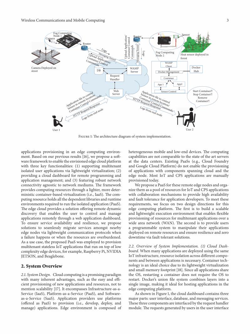
Framework Overhead. To test the case of the frameworkoverhead for supporting multitenant applications, we evalu-ated the CPU and memory consumption of the edge nodewhen multiple containers are launched on the two agents. Asshown in Figures 9(a) and 9(b), the CPU time and memoryare calculated by averaging the results from ten attempts oflaunching multiple containers varying from 0 ∼ 3. All in all,CPU consumption of the standalone agent is 2.36 times betterthan the master, while the overall CPU overhead is small,with less than 5%. The memory overhead does not changesignificantly when increasing the number of containers sincethe tenant container resides on the disk rather than thememory.
Hardware Independence. The total time required tocreate the container depends on the image size and type aswell as the overhead time of our service layers in our edgecomputing framework. We developed the service layer usingmessaging-driven transparent APIs andmake it independentof different hardware platforms.This flexibility is very impor-tant in utilizing different hardware platforms from differentvendors to create a common edge-computing platform formultitenant applications. To analyze the system overhead,we performed the container creation operation on differentplatforms, i.e., Beaglebone Black, NVIDIA Jetson TX1, andIntel desktop computer having the configuration of Inteli5-3320M, a clock speed of 2.6GHz, and 8 GB of physicalmemory. It was observed that container creation time doesnot differ much from different platforms. The difference ofabout 0.15 milliseconds is the amount of time consumed byour platform on the end node. This time is approximatelyequal across platforms: BeagleboneBlack (ARMCPU), JetsonTX1 (ARMCPU), and the computer with an Intel CPU (X86).
Container Density. The key feature of our proposededge-computing platform lies in the multitenancy support.Specifically, one edge node can launch multiple isolatedcontainers and support multiple developer groups simulta-neously without interference. The number of containers to
be supported on an edge device depends on the availablecomputing resources and the size of each container. Wetested the following platforms: (1) the Beaglebone Black withtotal disk space of 4GB, available disk space of 1.8GB; (2)NVIDIA Jetson TX1 with total disk space of 16GB, availabledisk space of 4.6GB; and (3) Intel computer with total diskspace of 256GB, available disk space of 118GB. One Ubuntuimage of 188MB was considered for analysis. On BeagleboneBlack, we observed that, with the creation of eight containers,the system was overloaded and slowed down. Hence, it isrecommended to use light weight containers with the sizeof 5MB to 40MB. On Jetson TX1, 15 containers were createdand the system performance did not degrade. There were nolimitations on the computer since the available disk space wasmuch higher.
6.4. Deploy andManageMultitenant Applications. Our dash-board provides functions for users to upload their appli-cations to the remote containers in the edge node. Theapplications can be the source code, compiled executablefiles, or Jave compressed packages. To facilitate multipleapplication file requirement, we utilize a common format(.tar) for all applications. When users want to upload theirapplications to the edge node, they need to prepare theirapplication in terms of the.tar format. Then, the web serverwill transfer the application file uploaded by the user to theedge node through our messaging service layer using twosteps: (1) transfer the application file to the web server and(2) transfer the application file from the web server to theedge node. The file size varies from 4 KB to 15 MB. Theperformance analyzed here is in comparison to theoreticalvalues calculated by the formula “file size × 8 / networkbandwidth.” Overhead of 50% is added for file sizes lesserthan 1 MB and 10% for file sizes greater than 1MB.
Transfer the Application File to the Web Server. Toevaluate the performance of uploading an application file

12 Wireless Communications and Mobile Computing
0.193 0.808
4.76
11.03
0.00360.768
3.53
10.61Ti
me T
ake (
sec)
0.004 151 5 Application Size (Mb)
Our PlatformTheoretical
0
2
4
6
8
10
12
(a) To the web server
0.623
2.83
7.13
0.1440.00170.33
1.67
5.008
Application Size (Mb)0.004 151 5
Our PlatformTheoretical
Tim
e Tak
e (se
c)
012345678
(b) To the edge node
Figure 10: The time taken to transfer the application file (a) to the web server and (b) to the edge node.
from the user dashboard toWebServer, we perform time con-sumption calculations based on a fixed network bandwidth(11.45Mbps as the upload speed). The network bandwidth isassumed to be constant over the course of evaluation.
The web server reads the compressed application fileusing “multer” and uploads serially through an HTTPrequest. The uploaded file is then moved to a unique storagespace with a unique ID. When the file is too big, wedivide them into several small compressed files, which arethen transferred. The total time consumed includes the filecompression, division, and transfer. As shown in Figure 10(a),the results show that the time consumed is almost linearwith the increase in application files. The difference in timeobserved is due to the time taken by our platform to processthe data, create a directory, upload the file, and update thedatabase.
Transferring the Application File to the Edge Node.Application files uploaded by the user are transferred fromthe user dashboard to the remote node and installed bythe application into the deployed container. This sectionanalyzes the performance by measuring the time to transferthe application file from the server to edge node. The fixeddownload bandwidth (24.2Mbps) is utilized in the evaluationprocess. The network bandwidth is assumed to be constantover the course of evaluation.
Our platform transfers the compressed application file byreading a chunk of data stored on the server and transmittingit to end node serially through anHTTP request.The receivedchunk of data is stored on a file locally on the end node.Several compressed files were transferred from server to theedge node, and the time consumed by each compressed filewas recorded. The file size varied from 4 KB to 15 MB.As shown in Figure 10(a) and Fig. ??, the time consumedwas almost linear with respect to the application size. Thedifference in time observed is due to the time taken by ourplatform to fetch the data, assemble the file, and load theapplication to the container. This analysis was performed onthe hardware of the Begalebone Black.
To test the performance independence on different hard-ware platforms, we conduct the evaluation of the time takento transfer the application file to the edge node in different
platforms: Begalebone Black, NVIDIA Jetson TX1, and acomputer having the configuration of Intel i5-3320M, with2.6GHz clock and 8GB of physical memory. As shown inFigure 11(a), there was a negligible amount of time differencewhen performed on different platforms.
Sending Commands and Debugging the Edge Node.The WAMP messaging protocol was used in our platformto communicate between server and end node, for example,transmitting a command from the user dashboard to theend node to obtain a response. WAMP protocol is anasynchronous communication protocol, which is an addedadvantage of our platform. Our platform makes use of thepublish and subscribe feature ofWAMP.While transmitting acommand from the server to end node or while transmittinga response from the end node to the server, commands andresponse are noted in a string format. The string size differsfor various commands and responses. It was observed thatthe time taken to transfer a string of 56 characters (56 bytes)was around 1.68 milliseconds. Different commands fromusers were translated to a string which constituted differentsizes; hence time consumed to transfer a command fromthe server to end node varied from 1.68 milliseconds to 2.37milliseconds. Similarly, a response from the end node to theserver was timed, and it was observed that the time consumedwas in the range of 2.53 milliseconds to 2.84 milliseconds.
As a user requests to fetch the log file for the debuggingpurpose, a command from the cloud dashboard is transferredto the edge (end) node and fetches the log result file fromthe edge node to the cloud dashboard. The transfer of thefile from the edge node to Webserver is achieved with thehelp of HTTP protocol. The log file available on the endnode is read in the form of chunk and is transmitted fromthe edge node to cloud dashboard. The received chunk iscopied onto a file on the server until the end of the file.Different sized result files were considered to measure thetime taken. An upload speed of 11.45Mbps is consideredduring the evaluation. Figure 11(b) shows the required timeto fetch the log file with respect to different file sizes. Thedifference in time is due to the time caused by our platformto send a message from the Webserver to end node, processthe request, copy the file from the container to the local path,

Wireless Communications and Mobile Computing 13
Tim
e Tak
en (s
ec)
0.004 151 5 Application Size (Mb)
012345678
BegalboneJetson Tx1
Laptoptheoretical
(a) Different platforms
Tim
e Tak
en (s
ec)
0.289
1.245
1.823
4.437
0.0053
1.0381.382
3.168
0.004 1 1.3 2.8Log file Size (Mb)
Our Platformtheoretical
00.5
11.5
22.5
33.5
44.5
5
(b) Log files
Figure 11: (a)The time taken to transfer the application file to the edge node in different hardware platforms and (b) the time taken to transferthe log file from the edge node to the cloud dashboard.
Different modulesChoosing peer node Sending small files Sending big files Migration in the peer node
0
225
450
675
900
Late
ncy
(ms)
Figure 12: The latencies for different components.
locate the file, and then transfer to the cloud. This analysismeasures the time required for the complete procedurewhichconsists of sending a command from user dashboard, routingthe command to a particular edge node, copying the file fromcontainer to the local path on the edge node, transferring thefile from to the server, pointing to the messaging service layto download, and transferring of file to the user dashboard.
6.5. The Evaluation of the Service Migration. Latency Testof the Service Migration. To quantify the latency of theservice migration between peer nodes, we conducted thelatency tests for different modules at the different stagesof the service migration. Figure 12 shows the latency costsfor different modules in service migration. We evaluate thelatency in the primary node and the peer node, respectively.Module 1 (selecting the peer nodes), module 2 (sending smallconfiguration files), and module 3 (sending big dependencyfiles) in Figure 12 are measured in the primary node. The
completion of the protocol to choose a working peer nodetakes 586 ms. Once the working secondary node is chosen,sending configuration and dependency files is much faster.For example, 60kB of data takes 36 ms. The delay of mod-ule 4 is measured in the peer node, which calculates thetotal migration time taken between receiving the “ResourceRequest” and finishing the “Activate Subscription.”
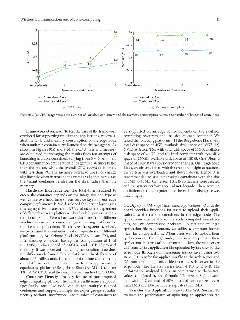
Resource Utilization during Service Migration. Thisexperiment uses two edge nodes as one example to evaluatethe coordinated servicemigration and the impact on theCPUutilization. Once the error happens, or the capacity limits arereached in the primary edge node, the agent in the primaryedge node will initiate a service migration request to its peernode. At this point even if connected sensor nodes continueto publish messages, the MQTT broker stores the messagesin the queue until the service is migrated. The exchangedmessages between these two peer nodes include commandsand the corresponding executable routines. When the initial
14 Wireless Communications and Mobile Computing
Time (in Seconds)0 2 4 6 8 10 12 14 16 18
CPU utilization of primary nodeCPU utilization of peer node
0
10
20
30
40
CPU
Util
izat
ion
(Per
cent
age)
Figure 13: The CPU utilization of the primary node and peer nodeduring service migration.
message exchange is finished, the primary node starts totransfer the dependent files to the peer node. Figure 13shows the CPU workload of the two peer nodes duringmigration. When the service migration happens, the CPUutilization of the primary gradually reduces to zero, while thepeer node’s CPU utilization increases after the user’s servicesare migrated. The peer node starts to perform the servicecomputations received from the data source.The initial spikein the secondary node’s CPU performance is due to theprocessing of the “RequestResource” command.
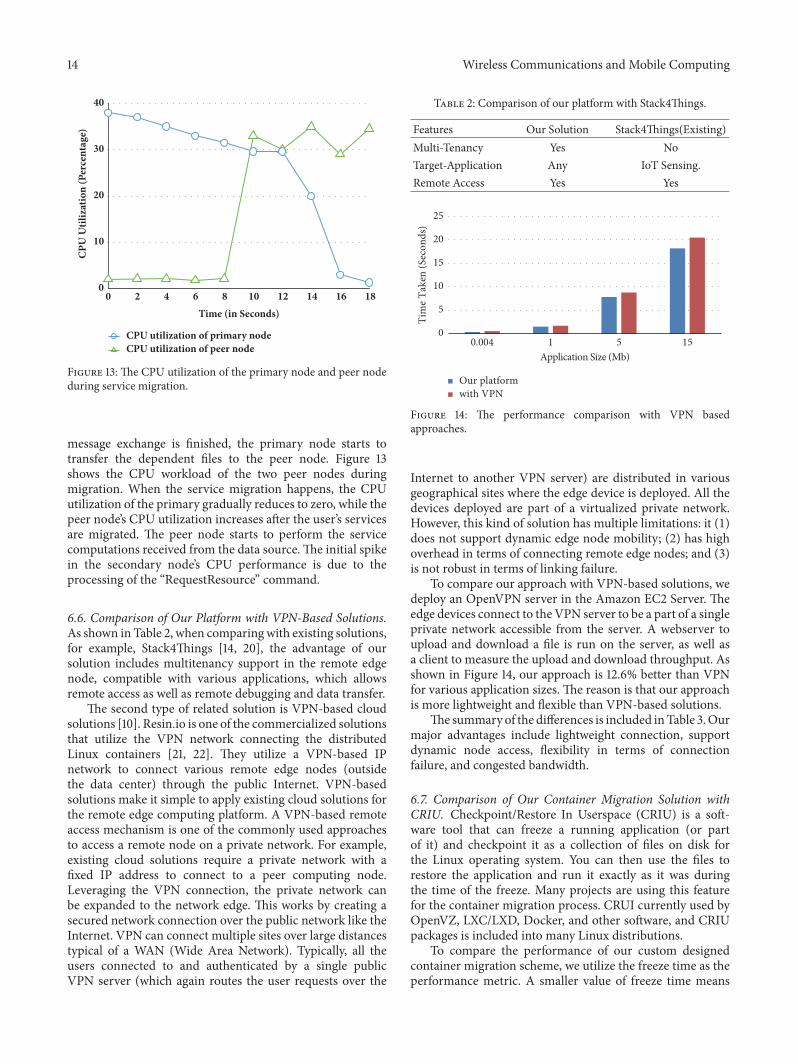
6.6. Comparison of Our Platform with VPN-Based Solutions.As shown in Table 2, when comparingwith existing solutions,for example, Stack4Things [14, 20], the advantage of oursolution includes multitenancy support in the remote edgenode, compatible with various applications, which allowsremote access as well as remote debugging and data transfer.
The second type of related solution is VPN-based cloudsolutions [10]. Resin.io is one of the commercialized solutionsthat utilize the VPN network connecting the distributedLinux containers [21, 22]. They utilize a VPN-based IPnetwork to connect various remote edge nodes (outsidethe data center) through the public Internet. VPN-basedsolutions make it simple to apply existing cloud solutions forthe remote edge computing platform. A VPN-based remoteaccess mechanism is one of the commonly used approachesto access a remote node on a private network. For example,existing cloud solutions require a private network with afixed IP address to connect to a peer computing node.Leveraging the VPN connection, the private network canbe expanded to the network edge. This works by creating asecured network connection over the public network like theInternet. VPN can connect multiple sites over large distancestypical of a WAN (Wide Area Network). Typically, all theusers connected to and authenticated by a single publicVPN server (which again routes the user requests over the
Table 2: Comparison of our platform with Stack4Things.
Features Our Solution Stack4Things(Existing)Multi-Tenancy Yes NoTarget-Application Any IoT Sensing.Remote Access Yes Yes
0.004 1 5 15Application Size (Mb)
Our platformwith VPN
0
5
10
15
20
25
Tim
e Tak
en (S
econ
ds)
Figure 14: The performance comparison with VPN basedapproaches.
Internet to another VPN server) are distributed in variousgeographical sites where the edge device is deployed. All thedevices deployed are part of a virtualized private network.However, this kind of solution has multiple limitations: it (1)does not support dynamic edge node mobility; (2) has highoverhead in terms of connecting remote edge nodes; and (3)is not robust in terms of linking failure.
To compare our approach with VPN-based solutions, wedeploy an OpenVPN server in the Amazon EC2 Server. Theedge devices connect to the VPN server to be a part of a singleprivate network accessible from the server. A webserver toupload and download a file is run on the server, as well asa client to measure the upload and download throughput. Asshown in Figure 14, our approach is 12.6% better than VPNfor various application sizes. The reason is that our approachis more lightweight and flexible than VPN-based solutions.
The summary of the differences is included inTable 3.Ourmajor advantages include lightweight connection, supportdynamic node access, flexibility in terms of connectionfailure, and congested bandwidth.
6.7. Comparison of Our Container Migration Solution withCRIU. Checkpoint/Restore In Userspace (CRIU) is a soft-ware tool that can freeze a running application (or partof it) and checkpoint it as a collection of files on disk forthe Linux operating system. You can then use the files torestore the application and run it exactly as it was duringthe time of the freeze. Many projects are using this featurefor the container migration process. CRUI currently used byOpenVZ, LXC/LXD, Docker, and other software, and CRIUpackages is included into many Linux distributions.
To compare the performance of our custom designedcontainer migration scheme, we utilize the freeze time as theperformance metric. A smaller value of freeze time means

Wireless Communications and Mobile Computing 15
Table 3: The performance comparison with VPN-based approach.
Our Approach VPN based remote accessRequires no network configuration.Provides automatic registration of device whendeployed in any private network.
Requires configuration of VPN server running parallelwith the platform service on the server.
Gives a consistent latency for upload and download,independent of the location of the device.
Latency is highly influenced by the distance betweenthe device and the server.
Gives auto-reconnect when the device is deployed inunreliable network. VPN server may or may not provide auto-connectivity.
Requires limited bandwidth as it uses WAMPmessaging.
VPN connectivity relies on high bandwidth as itchannels the network over the Internet.
CRIUOur solution
web app looperDifferent container imagesHello-world training/postgres Busybox
0
1
2
3
4
5
6
7
8
9
10
Free
ze T
ime
(s)
Figure 15: Comparison of our container migration solution with CRIU.
better service availability. As shown in Figure 15, our solutionachieves better service availability than CRIU for differentcontainer images, i.e., web app, hello-world container image,sql server training/postgres, a busybox in backend, and alooper image which loops numbers indefinitely.
7. Related Work
Mobile Edge Computing (MEC). Mobile edge computing(MEC), which provides cloud computing capabilities, offersa new paradigm to liberate mobile devices from heavy com-putation workloads [4]. In conventional cloud computingsystems, remote public clouds, e.g., Amazon Web Services,Google Cloud Platform, and Microsoft Azure, are leveraged,and thus long latency may be incurred due to data exchangein wide area networks (WANs) [5]. In contrast, MEC hasthe potential to significantly reduce latency, avoid congestion,and prolong the battery lifetime of edge devices. The firstform of the edge computing is the cloudlet [23–25]. Theidea behind the cloudlet is to place computers with highcomputation power at strategic locations in order to provideboth computation resources and storage in vicinity [4]. Howto offload the computation tasks from the mobile devices to
a physically proximate MEC server remains a major researchchallenge [4, 17, 25].
A more general concept of the edge computing, whencompared to cloudlets, is known as a fog computing (intro-duced by Cisco in 2012) [8]. The key motivation is to enablea processing of the Internet of Things (IoT) and big dataapplications on billions of connected devices at the edge ofnetwork [26]. Cisco, along with other big industry players,e.g., Intel, Dell, and ARM, formed an open fog consortium[11] in 2015. While the MCC is a fully centralized approachwith farms of computers usually placed at one or fewlocations, edge computing is meant to be deployed in a fullydistributed manner. On the other hand, the edge computingprovides only limited computational and storage resourceswith respect to themobile cloud computing (MCC).With fogcomputing, some of the components of an application couldbe hosted and executed in a cloud Platform-as-a-Service(PaaS) and interact with the other components hosted andexecuted in the fog, thus closer to the end-user and/or datasources such as wireless sensors [17].
As edge computing is gaining the much-deserved pop-ularity, recent years have seen the evolution of many edgecomputing platform solutions.These platform solutions often

16 Wireless Communications and Mobile Computing
provide a set of software services that offloads the data on thenetwork, which is then usually sent to the centralized cloud.Some of the major players in the edge cloud are companieslike Cisco and Akamai [10, 27–29]. Akamai cloudlets providevendor application that is designed to solve specific businessand operational challenges [20, 30]. This is Software as aService at the network edge. Cisco IoX [28] is a fog computingplatform that provides a single VM instance of Linux forcomputing which runs beside their network OS on routers,switches, etc. The application runs alongside the network OSthat obtains sensor data from the wireless network for theedge computed tasks. CMU Cloudlets [12] adopt a similarframework of fog computing, in which a Cloudlet server,similar to the Fog server, is deployed in the proximityof mobile users and processes the computing requests ofmobile devices in real time for video streaming and dataprocessing.
OpenStack [31, 32] is an open source cloud managementsoftware platform that manages the underlying hardwareinfrastructure to provide computing, storage, andnetworkingresources to third-party user applications. OpenStack canbe extended to cloudlet at the network edge to providerobust services [15]. For example, Stack4Things [14] andOpenStack++ [15] provide an OpenStack-based edge cloudframework for “Sensing and Actuation as a Service” [33, 34].The open edge computing community also claims to providethe extension of OpenStack to the cloudlet [11]. However, theintegration of various server-oriented technologiesmakes thesystem heavy and expensive to use in low-complex IoT andCPS applications.
8. Conclusions
This paper proposes an edge computing platform solution fordevelopers to remotely orchestrate edge devices without car-ing about their physical location, or their network configura-tion. Leveraging theminimal usage of network bandwidth viaasynchronous communication between servers and clients,we enable developers to deploy applications in a virtualizedspace, debug, analyze their performance, and retrieve theresults of the remote applications. We utilize the Dockertechnology to provide a lightweight virtual space in the formof containers, which consume less memory when comparedto virtual machines, thus providing an advantage due tothe memory constraints of embedded environments. Toimprove the system resilience, we proposed a fusion link thatautomatically selects the available connectivity services basedon WAN and 6LoWPAN. We utilize the MQTT protocol toprovide a unified connectivity interface for developers. Ourplatform is useful for applications that require low latencywith a dynamic andunpredictableworkload, and also in someapplications where there is no fixed IP address for connec-tions to be established between the user and end nodes. Forthe future research direction, we will further reduce overheadwhen deploying the applications. Specifically, we will enablea secure shell option to a specific container, which will allowdevelopers to have fine-grained control of the container.We will also enable sensor and hardware interface sharingbetween multiple containers.
Data Availability
The data used to support the findings of this study areavailable from the corresponding author upon request.
Disclosure
Abhishek Gurudutt is now with Nexteer Automotive. Tejesh-war Kamaal is now with Simplehuman LLC. ChinmayiDivakara is now with Amazon Lab126. Praveen Prabhakaranis now with Owl cameras.
Conflicts of Interest
The authors declare that they have no conflicts of interest.
Acknowledgments
The work presented in this paper is funded by Cisco Systemsand National Science Foundation under Grant No. CNS1637371.
References
[1] I. Stojmenovic, “Fog computing: A cloud to the ground supportfor smart things and machine-to-machine networks,” in Pro-ceedings of the 2014 Australasian Telecommunication Networksand Applications Conference, ATNAC ’14, pp. 117–122, Australia,2014.
[2] T. H. Luan, L. Gao, Z. Li, Y. Xiang, G. Wei, and L. Sun, “Fogcomputing: Focusing on mobile users at the edge,” https://arxiv.org/abs/1502.01815, 2015.
[3] M. Yannuzzi, R. Milito, R. Serral-Gracia, D. Montero, and M.Nemirovsky, “Key ingredients in an IoT recipe: fog computing,cloud computing, and more fog computing,” in Proceedingsof the IEEE 19th International Workshop on Computer AidedModeling and Design of Communication Links and Networks(CAMAD ’14), pp. 325–329, Athens, Greece, 2014.
[4] P. Mach and Z. Becvar, “Mobile Edge Computing: A Survey onArchitecture and Computation Offloading,” IEEE Communica-tions Surveys & Tutorials, vol. 19, no. 3, pp. 1628–1656, 2017.
[5] Y. Mao, J. Zhang, and K. B. Letaief, “Dynamic ComputationOffloading for Mobile-Edge Computing with Energy Harvest-ingDevices,” IEEE Journal on SelectedAreas inCommunications,vol. 34, no. 12, pp. 3590–3605, 2016.
[6] H. T. Dinh, C. Lee, D. Niyato, and P. Wang, “A survey of mobilecloud computing: Architecture, applications, and approaches,”Wireless Communications andMobile Computing, vol. 13, no. 18,pp. 1587–1611, 2013.
[7] C.-H.Hsu, S.Wang, Y. Zhang, andA.Kobusinska, “Mobile EdgeComputing,”Wireless Communications and Mobile Computing,vol. 2018, Article ID 7291954, 3 pages, 2018.
[8] F. Bonomi, R. Milito, J. Zhu, and S. Addepalli, “Fog computingand its role in the internet of things,” in Proceedings of theFirst Edition of theMCCWorkshop onMobile Cloud Computing,MCC ’12, pp. 13–16, ACM, 2012.
[9] F. Bonomi, R. Milito, P. Natarajan, and J. Zhu, “Fog computing:A platform for internet of things and analytics,” in Big Data andInternet ofThings: A Roadmap for Smart Environments, pp. 169–186, Springer, 2014.

Wireless Communications and Mobile Computing 17
[10] L. M. Vaquero and L. Rodero-Merino, “Finding your way inthe fog: Towards a comprehensive definition of fog computing,”Computer Communication Review, vol. 44, no. 5, pp. 27–32,2014.
[11] G. I. Klas, “Fog computing andmobile edge cloud gainmomen-tum open fog consortium etsi mec and cloudlets,” 2015.
[12] M. Satyanarayanan, “Cloudlets: at the leading edge of cloud-mobile convergence,” in Proceedings of the 9th InternationalACMSigsoft Conference onQuality of Software Architectures, pp.1-2, ACM, 2013.
[13] X. Chen, L. Jiao, W. Li, and X. Fu, “Efficient multi-user compu-tation offloading formobile-edge cloud computing,” IEEE/ACMTransactions on Networking, vol. 24, no. 5, pp. 2795–2808, 2015.
[14] F. Longo, D. Bruneo, S. Distefano, G. Merlino, and A. Puliafito,“Stack4Things: An OpenStack-Based Framework for IoT,” inProceedings of the 2015 3rd International Conference on FutureInternet of Things and Cloud (FiCloud ’15), pp. 204–211, 2015.
[15] K. Ha and M. Satyanarayanan, Openstack++ for CloudletDeployment, School of Computer Science Carnegie MellonUniversity Pittsburgh, 2015.
[16] K. Liu, A. Gurudutt, T. Kamaal, C. Divakara, and P. Prab-hakaran, “Edge computing framework for distributed smartapplications,” in Proceedings of the 2017 IEEE SmartWorld,Ubiquitous Intelligence & Computing, Advanced & TrustedComputed, Scalable Computing&Communications, Cloud&BigData Computing, Internet of People and Smart City Innovation(SmartWorld/SCALCOM/UIC/ATC/CBDCom/IOP/SCI), IEEE,2017.
[17] S. Yangui, P. Ravindran, O. Bibani et al., “A platform as-a-service for hybrid cloud/fog environments,” inProceedings of theIEEE International Symposium on Local and Metropolitan AreaNetworks (LANMAN ’16), pp. 1–7, IEEE, 2016.
[18] S. McDaniel, S. Herbein, and M. Taufer, “A Two-TieredApproach to I/O Quality of Service in Docker Containers,” inProceedings of the 2015 IEEE International Conference on ClusterComputing (CLUSTER), pp. 490-491, IEEE, 2015.
[19] D. Bernstein, “Containers and cloud: from LXC to docker tokubernetes,” IEEE Cloud Computing, vol. 1, no. 3, pp. 81–84,2014.
[20] G. Merlino, D. Bruneo, S. Distefano, F. Longo, and A. Puliafito,“Stack4Things: Integrating IoT with OpenStack in a Smart Citycontext,” in Proceedings of the 2014 International Conference onSmart Computing Workshops, (SMARTCOMP Workshops ’14),pp. 21–28, IEEE, 2014.
[21] A. Wilson, “Cellular man-in-the-middle detection with stich,”Linux Journal, vol. 2017, no. 274, p. 1, 2017.
[22] “Resin.io makes it simple to deploy, update, and maintain coderunning on remote devices,” https://resin.io.
[23] G. A. Lewis, S. Echeverrıa, S. Simanta, B. Bradshaw, and J.Root, “Cloudlet-based cyber-foraging for mobile systems inresource-constrained edge environments,” in Proceedings of the36th International Conference on Software Engineering, pp. 412–415, ACM, 2014.
[24] G. Lewis, S. Echeverria, S. Simanta, B. Bradshaw, and J. Root,“Tactical Cloudlets: Moving Cloud Computing to the Edge,”in Proceedings of the 2014 IEEE Military CommunicationsConference (MILCOM ’14), pp. 1440–1446, IEEE, 2014.
[25] K. Ha, Y. Abe, Z. Chen et al., “Adaptive vm handoff acrosscloudlets,” Technical Report CMU-CS-15-113, CMU School ofComputer Science, 2015.
[26] J. Zhu, D. S. Chan, M. S. Prabhu, P. Natarajan, H. Hu, andF. Bonomi, “Improving web sites performance using edgeservers in fog computing architecture,” in Proceedings of theIEEE 7th International Symposium on Service-Oriented SystemEngineering (SOSE ’13), pp. 320–323, IEEE, 2013.
[27] A. V. Dastjerdi, H. Gupta, R. N. Calheiros, S. K. Ghosh,and R. Buyya, “Fog computing: Principles, architectures, andapplications,” https://arxiv.org/abs/1601.02752, 2016.
[28] R. Mora, “Cisco iox: Making fog real for iot, blogs@ cisco-ciscoblogs,” 2015.
[29] Z. Pang, L. Sun, Z. Wang, E. Tian, and S. Yang, “A Surveyof Cloudlet Based Mobile Computing,” in Proceedings of the2015 International Conference onCloudComputing and BigData(CCBD ’15), pp. 268–275, IEEE, 2015.
[30] Y. Jararweh, A. Doulat, O. AlQudah, E. Ahmed, M. Al-Ayyoub,and E. Benkhelifa, “The future of mobile cloud computing:Integrating cloudlets andMobile Edge Computing,” in Proceed-ings of the 23rd International Conference on Telecommunications(ICT ’16), pp. 1–5, IEEE, 2016.
[31] O. Sefraoui, M. Aissaoui, and M. Eleuldj, “OpenStack: towardan open-source solution for cloud computing,” InternationalJournal of Computer Applications, vol. 55, no. 3, pp. 38–42, 2012.
[32] A. Solano, R. Dormido, N. Duro, and J. M. Sanchez, “A self-provisioning mechanism in openstack for IoT devices,” Sensors,vol. 16, no. 8, 2016.
[33] V. Herwig, R. Fischer, and P. Braun, “Assessment of REST andWebSocket in regards to their energy consumption for mobileapplications,” in Proceedings of the 2015 IEEE 8th InternationalConference on Intelligent Data Acquisition and Advanced Com-puting Systems: Technology and Applications (IDAACS ’15), pp.342–347, IEEE, 2015.
[34] G. Merlino, D. Bruneo, F. Longo, S. Distefano, and A. Puliafito,“Cloud-Based Network Virtualization: An IoT Use Case,” inProceedings of the International Conference on AdHoc Networks,pp. 199–210, Springer, 2015.

International Journal of
AerospaceEngineeringHindawiwww.hindawi.com Volume 2018
RoboticsJournal of
Hindawiwww.hindawi.com Volume 2018
Hindawiwww.hindawi.com Volume 2018
Active and Passive Electronic Components
VLSI Design
Hindawiwww.hindawi.com Volume 2018
Hindawiwww.hindawi.com Volume 2018
Shock and Vibration
Hindawiwww.hindawi.com Volume 2018
Civil EngineeringAdvances in
Acoustics and VibrationAdvances in
Hindawiwww.hindawi.com Volume 2018
Hindawiwww.hindawi.com Volume 2018
Electrical and Computer Engineering
Journal of
Advances inOptoElectronics
Hindawiwww.hindawi.com
Volume 2018
Hindawi Publishing Corporation http://www.hindawi.com Volume 2013Hindawiwww.hindawi.com
The Scientific World Journal
Volume 2018
Control Scienceand Engineering
Journal of
Hindawiwww.hindawi.com Volume 2018
Hindawiwww.hindawi.com
Journal ofEngineeringVolume 2018
SensorsJournal of
Hindawiwww.hindawi.com Volume 2018
International Journal of
RotatingMachinery
Hindawiwww.hindawi.com Volume 2018
Modelling &Simulationin EngineeringHindawiwww.hindawi.com Volume 2018
Hindawiwww.hindawi.com Volume 2018
Chemical EngineeringInternational Journal of Antennas and
Propagation
International Journal of
Hindawiwww.hindawi.com Volume 2018
Hindawiwww.hindawi.com Volume 2018
Navigation and Observation
International Journal of
Hindawi
www.hindawi.com Volume 2018
Advances in
Multimedia
Submit your manuscripts atwww.hindawi.com