software defined radio implementation of marine …
TRANSCRIPT

Tallinn 2017
TALLINN UNIVERSITY OF TECHNOLOGY
Faculty of Information Technology
Aleksei Fjodorov 142884IALB
SOFTWARE DEFINED RADIO
IMPLEMENTATION OF MARINE
AUTOMATIC IDENTIFICATION SYSTEM
(AIS)
Bachelor’s thesis
Supervisor: Julia Berdnikova
Master of Science

Tallinn 2017
TALLINNA TEHNIKAÜLIKOOL
Infotehnoloogia teaduskond
Aleksei Fjodorov 142884IALB
LAEVADE AUTOMAATSE
IDENTIFITSEERIMISE SÜSTEEMI (AIS)
RAKENDUS TARKVARALISE RAADIOGA
Bakalaureusetöö
Juhendaja: Julia Berdnikova
Magistrikraad

3
Author’s declaration of originality
I hereby certify that I am the sole author of this thesis. All the used materials, references
to the literature and the work of others have been referred to. This thesis has not been
presented for examination anywhere else.
Author: Aleksei Fjodorov
18.05.2017

4
Abstract
The following thesis describes the Software Defined Radio (SDR) implementation of
maritime Automatic Identification System. It contains the theoretical description of all
key fundamentals and standards used during the accomplishment of the main task and
the description of practical implementation process. The implementation part is
described in several chapters, including the radio signal reception, baseband and binary
signal processing.
The signal reception and processing was implemented in GNURadio software
environment and several external SDR receivers are used for RF (Radio Frequency)
reception. Binary data processing part describes the previously filtered, demodulated
and digitalized data decoding with necessary bit manipulations and the subsequent
NMEA message forming. The whole binary data processing was implemented as a
single computer program written in C programming language. It performs all the
necessary processing parts and provides most of the possible corruption checks.
The SDR implementation of signal transmitter is described in separate chapter. It
includes the description of possible AIS transmitter and the performed laboratory
condition test. The legal aspect includes the laws of Estonian Republic, which regulate
the exposed unauthorized transmissions on frequencies not intended for free use.
The following thesis also includes the financial aspect of the implemented SDR AIS
receiver. Moreover, the security part discusses the vulnerability of current AIS
standards according to results of this research, and possible steps to increase the security
of maritime Automatic Identification System.
This thesis is written in English and is 70 pages long, including 8 chapters, 55 figures
and 3 tables.

5
Annotatsioon
Alljärgnev bakalaurusetöö kirjeldab laevade Automaatse Identifitseerimise Süsteemi
(AIS) rakendust Tarkvara Raadioga (SDR). Töö sisaldab kõikide standartide ja
printsiipide teoreetilist kirjeldust, mis olid kasutatud põhiülesanne täitmise jooksul, ehk
praktilise rakenduse kirjeldust. Praktiline osa on kirjeldatud mõnedes peatükkides, mis
sisaldavad raadio signaalide vastuvõtt, põhiriba- ja binaarsignaalide töötlust.
Signaalide vastuvõtt ja nende töötlus olid rakendatud GNURadio tarkvara keskkonnas ja
mitmete SDR seadmete kasutades raadio signaalide vastuvõtmiseks. Binaarandmete
töötluse peatükk kirjeldab varem filtreeritud, demoduleeritud ning digitaliseeritud
andmete dekodeerimist kaasa arvatud vajalike bittide manipulatsioonidega, ehk
järgneva NMEA teatamise kujunemist. Kogu binaarandmete töötlus oli realiseeritud C
programmeerimiskeeles kirjutatud ühises programmis, mis täitab kõike vajalikud
töötluse osi ja tagab võimalikke andmevigade kontrollimist suuremas osas.
Signaalide saatja rakendus Tarkvara Raadioga on kirjeldatud eraldiolevas peatükkis.
Peatükk sisaldab võimalikku AIS signaalide saatja, ehk tehtud laboratoorses olukorras
saatmise testi kirjeldust. Õiguslik aspekt sisaldab Eesti Vabariigi seadusi, mis
reguleerivad mitte sanktsioneeritud signaaliedastust selle jaoks ette määratud
sageduskanalites.
Alljärgnev töö samuti sisaldab ka rakendatud AIS vastuvõtja finantsaspekti. Lisaks
turvalisuse osas käsitletakse vastavalt tulemustele uuringutele praeguse AIS standardite
kaitsmata kohti ja võimalikke samme Automaatse Identifitseerimise Süsteemi
turvalisuse suurenemiseks.
Lõputöö on kirjutatud Inglise keeles ning sisaldab teksti 70 leheküljel, 8 peatükki, 55
joonist, 3 tabelit.

6
List of abbreviations and terms
AIS Automatic Identification System
AI Shorted AIS abbreviation
SDR Software Defined Radio
GPS Global Positioning System
VHF Very High Frequency
MSK Minimum Shift Keying
GMSK Gaussian Minimum Shift Keying
TDMA Time Division Multiple Access
RATDMA Random Access TDMA
SOTDMA Self-Organized TDMA
ITDMA Incremental TDMA
FATDMA Fixed Access TDMA
NRZI Non Return to Zero Inverted
HDLC High-level Data Link Control
NMEA National Marine Electronics Association
UTC Coordinated Universal Time
FCS Frame Check Sequence
CRC Cyclic Redundancy Check
IMO International Maritime Organization
IEC International Electrotechnical Commission
ISO International Organization for Standardization
OSI Open Systems Interconnection
UHD USRP Hardware Driver
USRP Universal Software Radio Peripheral
RFIC Radio Frequency Integrated Circuit
FPGA Field-Programmable Gate Array
USB Universal Serial Bus
XOR Exclusive Or

7
VDM VHF Data-Link Message
VDO VHF Data-Link Own-Vessel Report
MMSI Maritime Mobile Service Identity
ASCII American Standard Code for Information Interchange
MID Maritime Identification Digits
GPP General Purpose Processor
DSP Digital Signal Processor
SoC System-on-a-Chip
TV Television
TX Transmitter
RX Receiver
USD United States Dollars

8
Table of contents
1 Introduction ................................................................................................................. 13
2 Automatic Identification System ................................................................................. 14
3 Theoretical basis and AIS standards ............................................................................ 15
3.1 Signal processing standards .................................................................................. 15
3.1.1 GMSK demodulation ..................................................................................... 15
3.1.2 TDMA transmission protocol ........................................................................ 19
3.2 Binary data processing standards ......................................................................... 21
3.2.1 NRZI encoding and decoding ........................................................................ 21
3.2.2 HDLC frame standards .................................................................................. 22
3.2.3 NMEA message standards ............................................................................. 24
3.3 Software Defined Radio ....................................................................................... 28
3.3.1 RTL-SDR ...................................................................................................... 28
3.3.2 USRP SDR .................................................................................................... 29
3.3.3 GNURadio ..................................................................................................... 30
4 AIS receiver ................................................................................................................. 31
4.1 GNURadio scheme ............................................................................................... 34
4.1.1 Source units ................................................................................................... 36
4.1.2 Output units ................................................................................................... 38
4.1.3 Visualization units ......................................................................................... 38
4.1.4 Signal processing units .................................................................................. 39
4.1.5 NRZI decoding units ..................................................................................... 41
4.2 HDLC to AIS NMEA converter ........................................................................... 43
4.2.1 HDLC frame detection and payload copying ................................................ 46
4.2.2 Bit stuffing removal ....................................................................................... 48
4.2.3 HDLC FCS control ........................................................................................ 48
4.2.4 Bit-flipping .................................................................................................... 49
4.2.5 Fill bits adding ............................................................................................... 52
4.2.6 AIS NMEA message forming ....................................................................... 53
5 AIS transmitter ............................................................................................................ 57
5.1 AIS transmitter test ............................................................................................... 58
5.2 Security aspect ...................................................................................................... 61

9
6 Legal aspect ................................................................................................................. 62
7 Financial aspect ........................................................................................................... 63
8 Summary ...................................................................................................................... 65

10
List of figures
Figure 1. MSK Modulated signal [8] ............................................................................. 16
Figure 2. Impulse response of Gaussian filter [9] .......................................................... 17
Figure 3. Frequency response of Gaussian filter [9] ...................................................... 17
Figure 4. Structural scheme of GMSK modulator [11] .................................................. 17
Figure 5. GMSK modulator signals [9] .......................................................................... 18
Figure 6. Spectral density of GMSK modulated signal [9] ............................................ 18
Figure 7 Structural scheme of GMSK demodulator [11] ............................................... 18
Figure 8. TDMA frame structure for AIS channels [13] ................................................ 19
Figure 9. Standard TDMA slot structure ........................................................................ 20
Figure 10. NRZI encoding process [16] ......................................................................... 21
Figure 11. NRZI decoding process ................................................................................. 22
Figure 12. Standard HDLC frame structure ................................................................... 22
Figure 13. CRC-16-CCITT generative polynomial: [19] ............................................... 23
Figure 14. General structure of NMEA encapsulated sentence ..................................... 24
Figure 15. Structure of VDM/VDO encapsulated NMEA sentence .............................. 25
Figure 16. Structural scheme of typical RTL-SDR device [27] ..................................... 28
Figure 17. Used RTL-SDR USB device ......................................................................... 29
Figure 18. Structural scheme of USRP device [27]........................................................ 29
Figure 19. Used USRP B210 SDR device ...................................................................... 30
Figure 20. RTL SDR device assembled for AIS reception. ........................................... 31
Figure 21. Structural scheme of AIS receiver ................................................................ 32
Figure 22. The reception of AIS signals in HDSDR software. ...................................... 33
Figure 23. GNURadio scheme of AIS receiver .............................................................. 35
Figure 24. Spectrogram of received AIS signals ............................................................ 37
Figure 25. Spectral density of received signals .............................................................. 37
Figure 26. Spectrums of separately filtered AIS channels ............................................. 39
Figure 27. Spectral density of received AIS message .................................................... 40
Figure 28. Demodulated binary AIS frame signal .......................................................... 41
Figure 29. NRZI decoded AIS frame binary signal ....................................................... 41

11
Figure 30. Saved files with results of signal processing in GNURadio scheme ............ 42
Figure 31. Structure scheme of program “HDLC to AIS NMEA converter” ................ 43
Figure 32. Structural scheme of program’s DATA PROCESSING UNIT .................... 44
Figure 33. Program’s main menu ................................................................................... 44
Figure 34. Program’s file definition submenu ................................................................ 45
Figure 35. Preliminary file reading results ..................................................................... 45
Figure 36. Program’s channel definition submenu ......................................................... 46
Figure 37. Notification about successful stuffing bit removal process .......................... 48
Figure 38. Notification about successful CRC check ..................................................... 49
Figure 39. Notification about successful bit flipping process ........................................ 50
Figure 40. Vessel – source of example message [34]..................................................... 51
Figure 41. Photographed vessel – source of example message ...................................... 52
Figure 42. Notification about successful fill-bits adding ............................................... 52
Figure 43. AIS NMEA sentence for received example message ................................... 53
Figure 44. Displaying the decoded information and generated AIS NMEA message ... 54
Figure 45. Files with binary data processing results, created by the program ............... 54
Figure 46. Contents of log file about example message ................................................. 55
Figure 47. Contents of created message (Msg) file ........................................................ 55
Figure 48. Decoded in AisDecoder messages from Msg file ......................................... 56
Figure 49. DNURadio scheme of possible transmitter [36] ........................................... 57
Figure 50. Structural scheme of tested transmitter ......................................................... 58
Figure 51. Isolated channel for transmission test ........................................................... 58
Figure 52. GNURadio scheme for transmitter................................................................ 59
Figure 53. Spectrum of transmitted signals .................................................................... 59
Figure 54. Transmission in progress .............................................................................. 60
Figure 55. Appendix 1 link contents .............................................................................. 70

12
List of tables
Table 1 - List of AIS messages [22] ............................................................................... 26
Table 2 - Description of contents of data field of AIS messages type 1,2 and 3 [23] .... 27
Table 3 - Decoded data of example message ................................................................. 51

13
1 Introduction
Nowadays, the Automatic Identification System (AIS) is used to improve the safety and
navigation accuracy in shipping. AIS provides the navigation information exchange
between vessels and nearby land bases, beacons, buoys or other vessels. However, the
security level of navigation data in this system is low, so literally everyone with
sufficient knowledge and minimal resources can receive and decode this information, to
use for his own purposes.
The regulation requires AIS to be fitted aboard all ships of 300 gross tonnage and
upwards engaged on international voyages, cargo ships of 500 gross tonnage and
upwards not engaged on international voyages and all passenger ships irrespective of
size. The requirement became effective for all ships by 31 December 2004 [1].
The main goal of this thesis was to implement the AIS receiver based on Software
Defined Radio (SDR). The current implementation is not specific SDR type dependable
and allows to create AIS receiver or transmitter at minimal cost, demonstrating the
insecurity of current navigation information in AIS.
The receiver of AIS signals is fully implemented as a scheme in regular version of
GNURadio environment. It provides complete signal processing according to AIS
standards and saves the resulting bit sequence as binary file, which needs later post
processing. The separate computer program “HDLC to AIS NMEA”, written in C
programming language, covers the binary data post processing and according to the
received data generates the AIS NMEA messages. Those messages contain the complete
navigational information about its source which could be later appropriately decoded
and stored.
The following work is based on the version of AIS standards approved by International
Telecommunication Union in February 2014 [2].
14
2 Automatic Identification System
Automatic Identification Systems or AIS means a maritime navigation safety
communications system standardized by the International Telecommunication Union
(ITU), adopted by the International Maritime Organization (IMO). AIS is an automatic
and autonomous tracking system used extensively in ship transporting and provides
vessel navigational and other safety-related information automatically to appropriately
equipped shore stations, other ships, and aircraft. It receives automatically such
information from similarly fitted ships, monitors and tracks ships, and exchanges data
with shore-based facilities or satellite stations [3]. Performance standards for AIS were
adopted in 1998 [1].
AIS transponders (on vessel stations) include a GPS (Global Positioning System)
receiver which collects the subject vessel's position and movement details. Such
(dynamic) details along with other static information provided by the vessel's crew are
automatically broadcasted at regular intervals using Time Division Multiple Access
(TDMA) method on two specific VHF channels (161.975 MHz and 162.025 MHz - 87
& 88 old VHF channels) [4]. AIS transceivers use 9.6 kbps Gaussian Minimum Shift
Keying (GMSK) modulation over 25 kHz channels using the High-level Data Link
Control (HDLC) packet protocol for data encapsulation [5].
Every AIS station also receives and collects the same information from other stations
and according to it, the movement of the ships can be coordinated and the safety of ship
transporting can be increased.
15
3 Theoretical basis and AIS standards
The following part will contain the theoretical basis and standards of AIS, which are
taken as a basis for the following work. It includes the 3.1.Signal processing standards
part with radio data broadcasting standards, such as the GMSK modulation and
demodulation, TDMA standards of channel access method for multiple device
broadcasting. The 3.2.Binary processing standards part contains the binary data
processing standards used for AIS data encoding. It includes standards of NRZI data
encoding and decoding algorithms, data frame forming standards of HDLC protocol and
NMEA message forming standards.
3.1 Signal processing standards
The following part contains the theoretical basis of signal processing standards, which
are used during the AIS transmission process. It includes the description of GMSK
modulating and demodulating standards in the part 3.1.1; Part 3.1.2 contains standards
of TDMA method usage for the multiple station transmissions in VHF channels, TDMA
one-minute frame and its every slot structure. It also includes the description of every
TDMA protocol, which is used during the AIS transmission with their usage example.
3.1.1 GMSK demodulation
MSK (Minimum Shift Keying) modulation is one of the methods of CPFSK
(Continuous Phase Frequency Shift Keying) with index of frequency modulation equals
to m=0.5. The index m (1) determines how many times the separation of the modulation
frequencies Δf (2) exceeds the bit rate Br [6]. A modulation index of 0.5 corresponds to
the minimum frequency spacing that allows two FSK signals to be orthogonal detectied
over one bit intervall T:
𝑚 = ∆𝑓
𝐵𝑟 (1) [6]
∆𝑓 = |𝑓1 − 𝑓0| = 𝐵𝑟
2 (2) [7]

16
The example of MSK modulated signal is shown in Figure 1
Figure 1. MSK Modulated signal [8]
a) binary sequence at MSK modulator input, b) phase changes of modulated signal, c) MSK modulated
signal
GMSK (Gaussian Minimum Shift Keying) modulation represents the MSK modulation
with preliminary filtration in Gaussian filter. The impulse response g(t) (3) of the filter
is shown on Figure 2 and it depends on different BT parameter values. BT value (4)
could be calculated from filter -3 dB cut-off frequency response B-3dB multiplied by bit
rate Br (Figure 3):
𝑔(𝑡) =𝐵𝑇
𝑇∗ √
2∙𝜋
ln 2∗ 𝑒
−2∙𝜋2∙𝐵𝑇2∙𝑡2
ln 2∙𝑇2 , (3) [9]
𝐵𝑇 = 𝐵−3𝑑𝐵 ∗ 𝑇 (4) [10]
Where:
𝑇 = 1
𝐵𝑟

17
Figure 2. Impulse response of Gaussian filter [9]
Figure 3. Frequency response of
Gaussian filter [9]
Figure 4 shows the structural scheme of standard GMSK modulator. The initial data
binary signal is b0(t) (Figure 5a), which was preliminary normalized: to logical “1” and
“0” corresponds accordingly “1” and “-1” values of normalized binary signal b0(t).
Initial signal is being filtered in Gaussian filter, which was previously described,
afterwards the filtered signal bg(t) (Figure 5b) has to be integrated in the integration
unit. The resulting signal ϕ(t) (Figure 5c) represents the phase. It can be used further in
the quadrature modulator to generate quadrature Q(t) and in-phase I(t) components of
the resulting modulated signal. Spectral density of GMSK modulated signal with
different BT parameters is shown in Figure 6. As it can be seen, the wideness of central
lobe of GMSK modulated signal’s spectral density equals to 1.5 Br.
Figure 4. Structural scheme of GMSK modulator [11]

18
Figure 5. GMSK modulator signals [9]
Figure 6. Spectral density of GMSK modulated signal [9]
b0(t) - binary signal at the input, bg(t) - signal
filtered with Gaussian Filter, ϕ(t) – the signal
phase value.
The Figure 7 shows the structural scheme of GMSK demodulator, which calculates
quadrature Q(t) and in-phase I(t) components of initial GMSK modulated signal.
According to formula (5), the phase ϕ(t) of demodulated signal is being calculated. It
represents the integrated function of b0(t) signal, therefore, to receive the demodulated
signal b0(t), phase function must be differentiated in derivator unit.
Figure 7 Structural scheme of GMSK demodulator [11]
𝜑(𝑡) = tan−1 𝐼(𝑡)
𝑄(𝑡) (5)

19
3.1.2 TDMA transmission protocol
To provide multiple station access to VHF channels AIS is using the channel access
method for shared networks – Time Division Multiple Access (TDMA) method. It
allows several users to share the same frequency channel by dividing the signal into
different time slots [12]. TDMA transmission is divided into one-minute TDMA frames
as it is shown on the Figure 8. TDMA one-minute frame contains 2250 slots with length
about 26.67ms each. It allows to provide the transmission of up to 2250 reports per
minute.
Figure 8. TDMA frame structure for AIS channels [13]
The access of free slots for AIS transmitting station is regulated by different TDMA
protocols, which are depend on transmitting station permissions. The following
protocols are used for free slot management in current AIS standard:
RATDMA (Random Access) – protocol defines and takes first (random) unoccupied
slot for first message transmission. This protocol is used to start first transmission after
enabling AIS station and for sending special requested messages.
ITDMA (Incremental) – protocol reserves slots for reports in the current frame and is
used right after RATDMA protocol or for changing transmission frequency.
SOTDMA (Self-Organized) – protocol reserves slots for reports in the next 3-7 frames.
It is used as a continuation if ITDMA protocol.

20
FATDMA (Fixed Access) – protocol allows to use special fixed slots. It can only be
used by base stations to provide the stabile and continuous transmission of data-link
management and navigational assistance messages. Mobile AIS transmitters are not
allowed to use this protocol [14].
Since the transmission speed in both AIS channels is 9.6kbps and one TDMA slot is
26.67ms long, the capacity of every slot can be calculated in the following way:
9600bps * 26.67ms = 256 bit. Data transmission is realized according to HDLC
protocol and the slot structure is composed of the standard HDLC frame (excluding
unnecessary fields) with few additional blocks. The standard TDMA slot structure is
shown in the Figure 9 and it includes the following fields:
TDMA slot stats with ramp-up time period. Ramp-up time period equals to
0.8336ms or 8 transmitted bits. The ramp-up sequence presence reduces the
throughput of the channel but provides the clear separation of TDMA frame
slots and gives the station some time to prepare for transmission.
24 bits – Training sequence or preamble. Sequence of alternate “1” and “0” bits.
Preamble can either start with “1” or “0” (0101…01 or 1010…10). [15]
The following 200 bits contain the standard HDLC frame with 8-bit start and
stop flags, 16 bits of check sequence and 168 bits of actual transmitted data.
24 bits – Buffer area, reserved for bit stuffing, distance delay and
synchronization jitter. All the unused buffer bits by default represent the
sequence of “zeros”.
Figure 9. Standard TDMA slot structure

21
3.2 Binary data processing standards
The following part contains the theoretical basis and standards of binary data
processing, which are used during the AIS data exchange process. This part discusses
the NRZI encoding and decoding algorithms (3.2.1 part). Next, the HDLC frame
structure description, frame check sequence calculation and other bit manipulations are
described in the part 3.2.2. Part 3.2.3 contains the NMEA standards, the description of
NMEA message structure and it’s forming algorithm. This part also includes the list of
all used AIS message types with their short description and the example structure of
message types 1, 2 and 3.
3.2.1 NRZI encoding and decoding
Before the GMSK modulation and further transmission, the data bit sequence has to be
encoded. AIS system uses the Non-Return-to-Zero Inverted physical encoding or NRZI.
The NRZI encoder changes its value to opposite only when it receives logical “0” and
ignores all incoming logical “1”. Value of the encoded binary signal changes more
rarely, which makes it more solid and easy to transmit. Although, since every next bit
encoding depends of previous bit, first bit in a sequence will be lost during the data
decoding. NZRI encoding is shown on Figure 10.
Figure 10. NRZI encoding process [16]
To decode NRZI message it has to be used logical XOR unit to all neighbour pairs of
bits, and afterwards all bits in the formed bit sequence has to be inverted. NRZI
decoding process is shown on Figure 11.

22
Figure 11. NRZI decoding process
3.2.2 HDLC frame standards
High-Level Data Link Control or (HDLC) is a developed by ISO protocol of OSI
model’s data link layer and provides both connection-oriented and connectionless
service [17]. Since this protocol is bit-oriented, which means that it works directly with
bit stream without any semantics or meaning, it can be used in radio transmissions, and
particularly in AIS transmissions.
Figure 12. Standard HDLC frame structure
Figure 12 shows the structure of standard HDLC frame, which contains the following
fields:
8 bits HDLC Start and Stop flag sequences “01111110”, which represent the
beginning and the end of HDLC frame.
Address field, which contains address of the receiving device the data is
intended for. (Not used in AIS)

23
Control field contains 8 to 16 bits of control information with transmission
specifications. (Not used in AIS)
Data field, which contains data, which has to be transmitted. Should contain
integer number of 8-bit bytes.
Frame Check Sequence is 16bits checksum calculated for whole bits between
flags by using special polynomial. Usually are used different CRC16 algorithms.
For AIS transmissions are used the standard HDLC frames excluding address and
control fields since those functions are realized inside the data field.
To guarantee that the “Flag-sequence” (01111110) will not accidentally appear inside
the whole information field between the real start and stop flags, the bit-stuffing
manipulation is used: the transmitter is placing additional “0” bit after every 5
consecutive “1” bits. It ensures that fake stop-flag will not suddenly appear before the
end of frame.
HDLC frame check sequence is using 16 bit cyclic redundancy check (CRC-16) – error
detecting code. CRC is calculated over the whole data sequence between start and stop
flags in HDLC frame according to ISO/IEC 13239:2002 standard [18]. It can be
calculated by dividing the data sequence by specific 16 bit divisor which is called
“polynomial”.
For AIS transmissions, the HDLC FCS is being calculated by the CRC-16-CCITT
algorithm with a certain polynomial, which is shown in Figure 13a, b and c in
polynomial, hexadecimal and binary forms accordingly. AIS uses the CRC-16-CCITT
calculation algorithm with the following extra parameters: Initial value = 0xffff; Final
XOR value = 0xffff; No input or result reflection. CRC-16 calculation algorithm with
those parameters is also known as CRC-16/GENIBUS [19].
x16+x12+x5+1 0x1021 10001000000100001
a) b) c)
Figure 13. CRC-16-CCITT generative polynomial: [19]
in a) polynomial, b) hexadecimal and c) binary form.
24
3.2.3 NMEA message standards
NMEA or National Marine Electronics Association is a special text protocol, which
provides the communication between navigational equipment. The currently common
standard of this protocol is NMEA 0183. The improved version of this protocol –
NMEA 2000 is being distributed lately. The main improvement is ability to connect all
navigation equipment in one network, which increases the data exchange and
processing.
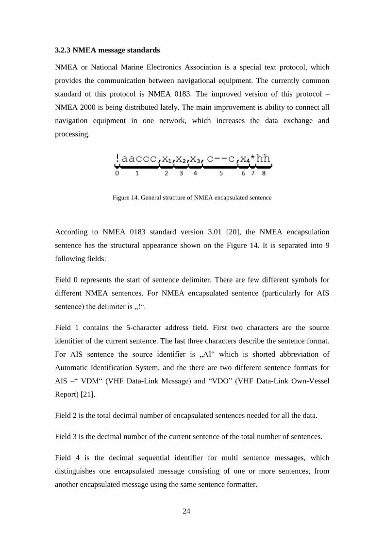
Figure 14. General structure of NMEA encapsulated sentence
According to NMEA 0183 standard version 3.01 [20], the NMEA encapsulation
sentence has the structural appearance shown on the Figure 14. It is separated into 9
following fields:
Field 0 represents the start of sentence delimiter. There are few different symbols for
different NMEA sentences. For NMEA encapsulated sentence (particularly for AIS
sentence) the delimiter is „!“.
Field 1 contains the 5-character address field. First two characters are the source
identifier of the current sentence. The last three characters describe the sentence format.
For AIS sentence the source identifier is „AI“ which is shorted abbreviation of
Automatic Identification System, and the there are two different sentence formats for
AIS –“ VDM“ (VHF Data-Link Message) and “VDO” (VHF Data-Link Own-Vessel
Report) [21].
Field 2 is the total decimal number of encapsulated sentences needed for all the data.
Field 3 is the decimal number of the current sentence of the total number of sentences.
Field 4 is the decimal sequential identifier for multi sentence messages, which
distinguishes one encapsulated message consisting of one or more sentences, from
another encapsulated message using the same sentence formatter.
25
Field 5 is the data containing block. The size of this field is fixed and determined by the
address field. Since all bits in this field are packed into six-bit ASCII characters, the
number of bits in this field should be a multiple of six. Otherwise, there will be added
from one to five extra bits – fill bits.
Field 6 contains the decimal number of quantity of fill bits were added at the end of data
to complete the last six-bit character (those bits will be ignored during the decoding).
Represents the number from 0 to 5.
Field 7 is the checksum delimiter, which separates the NMEA sentence and the NMEA
checksum field. It indicates the end of sentence.
Field 8 contains the NMEA checksum in two hexadecimal characters. The checksum is
calculated through Exclusive-Or operation of all characters between start “!” and stop
“*” delimiters in the sentence.
All sentence fields between start and stop delimiters are separated with the field
delimiter “,”. It delimits all the fields, even empty ones. In this case it has the following
view: “,,”.
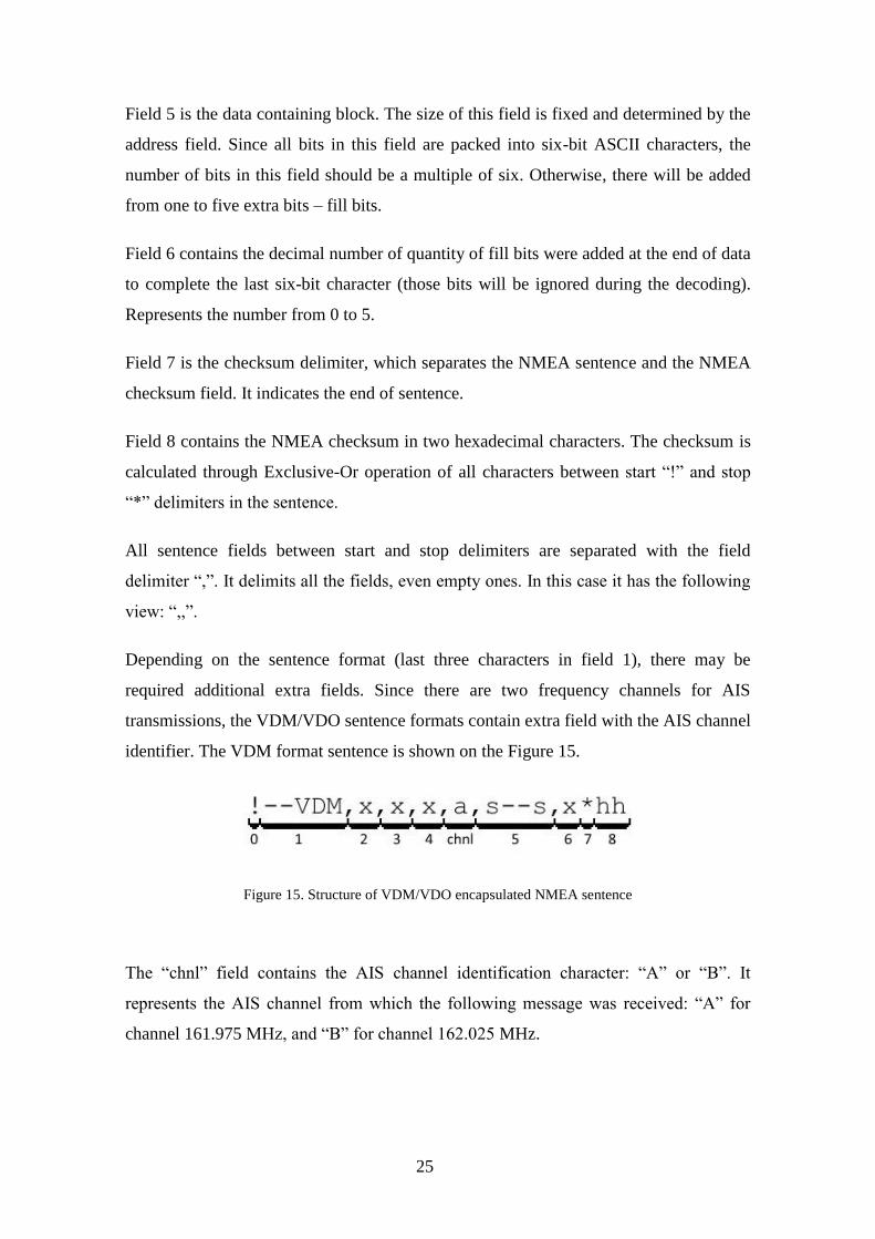
Depending on the sentence format (last three characters in field 1), there may be
required additional extra fields. Since there are two frequency channels for AIS
transmissions, the VDM/VDO sentence formats contain extra field with the AIS channel
identifier. The VDM format sentence is shown on the Figure 15.
Figure 15. Structure of VDM/VDO encapsulated NMEA sentence
The “chnl” field contains the AIS channel identification character: “A” or “B”. It
represents the AIS channel from which the following message was received: “A” for
channel 161.975 MHz, and “B” for channel 162.025 MHz.
26
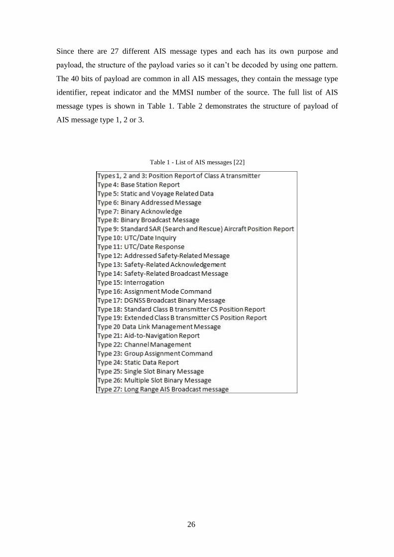
Since there are 27 different AIS message types and each has its own purpose and
payload, the structure of the payload varies so it can’t be decoded by using one pattern.
The 40 bits of payload are common in all AIS messages, they contain the message type
identifier, repeat indicator and the MMSI number of the source. The full list of AIS
message types is shown in Table 1. Table 2 demonstrates the structure of payload of
AIS message type 1, 2 or 3.
Table 1 - List of AIS messages [22]

27
Table 2 - Description of contents of data field of AIS messages type 1, 2 and 3 [23]

28
3.3 Software Defined Radio
Software-defined radio is the radio signal receiving or transmitting system, where all or
some of the radio frequency components (filters, mixers, amplifiers, modulating and
demodulating components, etc.) can be tuned by using special software instead of
physical changing of the radio device’s electric circuit. SDR devices usually can contain
programmable FPGA, GPP, SoC or DSP circuits [24]. Radio in which some or all of
physical layer functions are software defined [25].
3.3.1 RTL-SDR
RTL-SDR is a software defined radio receiver based on chipsets of RTL2832 ADC and
one of few various TV tuners, which determines the main characteristics of RTL-SDR
device [26]. Even in standard configuration it can be used as a basis to assemble a
relatively good radio receiver for a wide variety of purposes. During the current work it
was used the RTL-SDR device based on R820T tuner with the following characteristics:
Frequency Range: approx. 24 MHz – 1766 MHz
Bandwidth: 250 kHz - 2.5 MHz
Maximal Gain: 40 dB
TX/RX: RX Only
The structural scheme of used RTL-SDR device and the USB device are shown
accordingly on the figures Figure 16, and Figure 17a and b.
Figure 16. Structural scheme of typical RTL-SDR device [27]
29
a) [28] b)
Figure 17. Used RTL-SDR USB device
a) RTL-SDR USB device b) with standard antenna
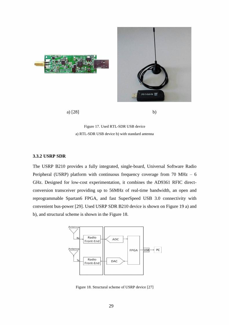
3.3.2 USRP SDR
The USRP B210 provides a fully integrated, single-board, Universal Software Radio
Peripheral (USRP) platform with continuous frequency coverage from 70 MHz – 6
GHz. Designed for low-cost experimentation, it combines the AD9361 RFIC direct-
conversion transceiver providing up to 56MHz of real-time bandwidth, an open and
reprogrammable Spartan6 FPGA, and fast SuperSpeed USB 3.0 connectivity with
convenient bus-power [29]. Used USRP SDR B210 device is shown on Figure 19 a) and
b), and structural scheme is shown in the Figure 18.
Figure 18. Structural scheme of USRP device [27]

30
a) [29] b)
Figure 19. Used USRP B210 SDR device
a) USRP B210 SDR board with USB interface and b) USRP B210 device with antennas and cables used
in practical part
3.3.3 GNURadio
The implementation of SDR receiver or transmitter requires special drivers and software
to be installed. One of the freeware applications is GNURadio.
GNURadio is a free software development toolkit with wide range of different default
radio components for signal receiving, transmission and processing. Each component is
written on C++ programming language or python programming language independent
application with necessary input and/or output values, adjustable processing parameters
and defined processing algorithms. Components are visualized as movable blocks with
one or several inputs, outputs and ability of changing the component’s working
parameters. Components can be combined into more complicated unit or a whole
scheme on the working field. GNURadio also gives an ability to add new written by
user components as extra blocks and use them further. GNURadio is free to download
and available for Windows/Linux/Mac.
31
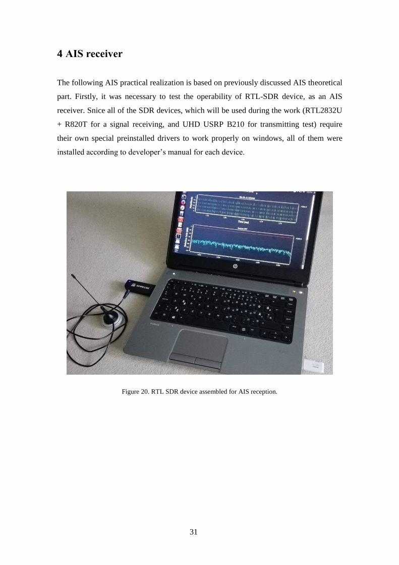
4 AIS receiver
The following AIS practical realization is based on previously discussed AIS theoretical
part. Firstly, it was necessary to test the operability of RTL-SDR device, as an AIS
receiver. Snice all of the SDR devices, which will be used during the work (RTL2832U
+ R820T for a signal receiving, and UHD USRP B210 for transmitting test) require
their own special preinstalled drivers to work properly on windows, all of them were
installed according to developer’s manual for each device.
Figure 20. RTL SDR device assembled for AIS reception.
32
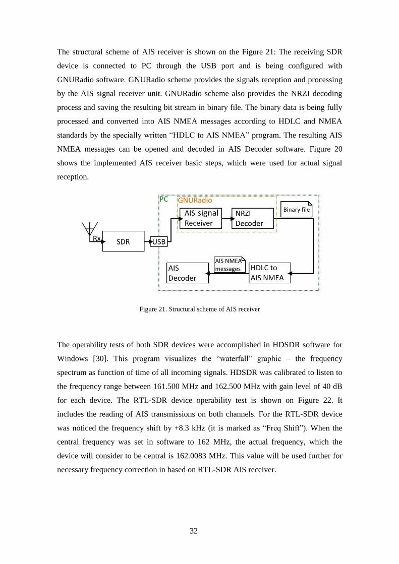
The structural scheme of AIS receiver is shown on the Figure 21: The receiving SDR
device is connected to PC through the USB port and is being configured with
GNURadio software. GNURadio scheme provides the signals reception and processing
by the AIS signal receiver unit. GNURadio scheme also provides the NRZI decoding
process and saving the resulting bit stream in binary file. The binary data is being fully
processed and converted into AIS NMEA messages according to HDLC and NMEA
standards by the specially written “HDLC to AIS NMEA” program. The resulting AIS
NMEA messages can be opened and decoded in AIS Decoder software. Figure 20
shows the implemented AIS receiver basic steps, which were used for actual signal
reception.
Figure 21. Structural scheme of AIS receiver
The operability tests of both SDR devices were accomplished in HDSDR software for
Windows [30]. This program visualizes the “waterfall” graphic – the frequency
spectrum as function of time of all incoming signals. HDSDR was calibrated to listen to
the frequency range between 161.500 MHz and 162.500 MHz with gain level of 40 dB
for each device. The RTL-SDR device operability test is shown on Figure 22. It
includes the reading of AIS transmissions on both channels. For the RTL-SDR device
was noticed the frequency shift by +8.3 kHz (it is marked as “Freq Shift”). When the
central frequency was set in software to 162 MHz, the actual frequency, which the
device will consider to be central is 162.0083 MHz. This value will be used further for
necessary frequency correction in based on RTL-SDR AIS receiver.

33
Figure 22. The reception of AIS signals in HDSDR software.
These tests allowed to determine the receiver settings: gain level for both devices is
40dB, which provides good noise-to-signal ratio and sample rate is 1 MHz. Both
devices worked properly and received AIS transmissions from both channels, which
means that both devices can be used as a basis for receiving, recording and processing
of the AIS transmitted data.
34
4.1 GNURadio scheme
The GNURadio toolkit was chosen as free software environment for setting up the SDR,
since it provides the wide range of basic digital signal processing functions, and it has
quite understandable graphic interface, which makes it convenient to use. For the
current work it was used the GNURadio version 3.7.10.1 for Ubuntu on bootable USB
flash drive [31], since the GNURadio versions for Ubuntu usually include the additional
extended functionality packages. The Windows versions of GNURadio require the
separate installation of those packages.
The AIS signal reception and binary NRZI decoding functions were realized in the
GNURadio signal processing environment. Implemented AIS receiver scheme is shown
in the Figure 23. This also can be found by the link from Appendix 1. Grey blocks are
currently disabled. Inputs/Outputs of all blocks are coloured according to the
input/output data types: blue – data in complex values, purple – binary data, orange –
data in float values.
Most of the blocks are indexed “a” or “b”. After the Throttle unit, the scheme is divided
into two parallel and identical parts. Each of them is processing the data from its own
specified AIS channel: blocks with index “a” are processing the data only from AIS
channel A (161.975 MHz or the central frequency of receiver 162 MHz – 25 kHz), and
blocks with index “b” are processing the data from AIS channel B (162.025 MHz or the
central frequency of receiver 162 MHz + 25 kHz).

35
Figure 23. GNURadio scheme of AIS receiver

36
GNURadio scheme for AIS signal reception includes four unit types: source units
represent the input of the scheme. It cooperates with the external SDR device, adjusts it
according to given parameters and provides the received signal to the scheme. Output
units represent the scheme outputs for processed data as files. Signal processing units
provide the necessary signal processing steps including the demodulation process. NRZI
decoding units are the binary data processing units, and they perform the NRZI
decoding process. Visualization units contain dispensable for main processing units
which are intended to demonstrate the progress of signal processing at each stage.
4.1.1 Source units
Block 1 – is an input source. The processing starts from this unit. There are three types
of source blocks:
RTL-SDR Source – this unit defines any RTL-SDR device connected to the PC,
synchronizes, sets it up by using specified parameters and uses it as physical
receiving device. It requires the following specified parameters: gain level,
central frequency of reading and sample rate.
Those parameters were defined earlier during the test signal reading: Gain level
= 40dB is optimal (maximum gain level for used RTL-SDR device is 49 dB),
Sample rate = 1 MHz (sample rate can be any value between 250kHz and 2.5
MHz for the current RTL-SDR device), Central frequency = 162 MHz - 8.3 kHz
= 161.9917 MHz. Since it was set to 162 MHz, both of the AIS channels are
placed on + and - 25 kHz frequencies away from the central frequency. As it
was mentioned earlier, the current RTL-SDR device has frequency shift by +8.3
kHz, therefore there has to be a frequency correction (-8.3 kHz), which will
compensate the shift.
UHD: USRP Source – this unit defines any USRP device connected to the
machine, synchronizes with it, sets it up by using specified parameters and uses
it as physical receiving device. It requires the same parameters, as the RTL-SDR
source does and therefore they remain the same: gain level = 40 dB (the USRP
device allows to increase the gain level up to 75 dB), central frequency = 162
MHz (without frequency correction, since the USRP has no frequency shit, and
nothing needs to be compensated), and sample rate = 1 MHz (for the USRP
device the sample rate parameter can be between 100 kHz and 5 MHz).

37
File source – this unit uses the specific previously recorded (by File Sink unit,
block No 2) file as a source of the signal. Since this unit uses the previously
recorded file with previously defined parameters of gain level, sample rate and
central frequency, they should be known and specified as variables for all
scheme for accurate data processing.
Figure 24 shows the spectrogram of input signal, which is received with RTL-SDR
device. Marked with arrows short-term points with high power on frequencies +25kHz
and – 25 kHz (shifted from the central frequency at 162 MHz) are the transmitted
frames with AIS data payload. The last power jump up point (message frame) will be
used further as an example. Figure 25 represents the spectral density of input signals.
The high power peak at the frequency of 161.975 MHz represents the transmitted
message frame in the AIS channel A. It corresponds to the example message frame.
Figure 24. Spectrogram of received AIS signals
Figure 25. Spectral density of received signals

38
4.1.2 Output units
Block 2 – is a File Sink or raw file recording unit. It is connected to all of the source
blocks, and once it is enabled during the processing, it will record the raw receiving data
and saved them in specified by user file. This file can be used as a source file in File
Source unit (block No 1).
Block 14 – the File Sink unit has the same purpose as the block No. 2. It is placed after
all processing blocks and saves the processed data bit stream into a binary file (file.bin)
for the future processing in the AIS NMEA message generator.
4.1.3 Visualization units
Blocks 3 – are the Waterfall Sink units. Waterfall Sink unit – visualisation unit, which
shows the spectrogram at the point it is connected to – graphic of the power of energy at
each frequency as a function of time. (Those units are not required for proper work of
the receiver)
Block 4 – is the Frequency Sink unit – visualisation unit, which shows the spectral
density of the signal at the point it is connected to. To show the spectral density of the
source signal at the current moment of time, it requires the Throttle unit (block No. 5)
between the signal source and itself to work properly.
Blocks 11, 12 and 13 – visualization units is the pair of units, which are used to
visualize the bit stream as a binary signal.
• Block 12 – is the UChar To Float unit. It is used to convert the binary stream
into the float type values for the future usage in the Time Sink unit (block No. 13)
• Block 13 – Time Sink is the visualization unit, which displays the incoming
value stream as a function of time.
• Blocks 11 – Correlate Access Code - Tag are the unnecessary blocks. Each
block has its own defined bit sequence – access code. It searches for a sequence of bits
that match the access code and marks them with a visual sign. In the current case the
access code is the preamble sequence with HDLC flag, which represents the start of AIS
message (It can be seen on the NRZI decoded binary signal, the red triangle right at the
end of start flag).

39
4.1.4 Signal processing units
Block 5 – Throttle unit, which limits the data throughput to the specified sampling rate
(1 MHz in the current scheme). It prevents the working scheme from consuming all PC
CPU resources.
Block 6 – is the Frequency FIR Filter, which cuts out the frequency of AIS channel with
sample rate of 25 kHz (since the highest frequency bandwidth of transmitting AIS
message can be 25 kHz). This unit requires the following specified parameters: Sample
rate equals to 1 MHz (sample rate of the incoming data. 1 MHz since the output data of
the source unit has the sample rate at 1 MHz), central frequency value = + or – 25 kHz
(the shift from the central frequency of the incoming signal, which is 162 MHz. -25 kHz
for the AIS channel A (161.975 MHz – scheme branch “a”), and +25 kHz for the AIS
channel B (162.025 MHz – scheme branch “b”)), the decimation value = 40 (forms the
sample rate of filter’s output signal depending of the sample rate of incoming signal.
The output sample rate equals to the input sample rate divided by decimation value). All
used parameters of the filter unit were taken from another source [15].
Spectrums of both filtered AIS channels are shown on Figure 26. Each horizontal blue
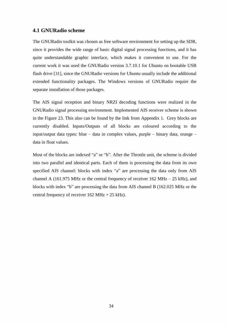
line represents to the transmitted message frame with AIS data. Figure 27 shows the
spectral density of the AIS channel A, which have already fixed the transmitted example
message frame (purple line). The spectral density represents the only 14.4 kHz wide
main lobe of spectral density, which confirms, that the signal was GMSK modulated.
Figure 26. Spectrums of separately filtered AIS channels
40
Figure 27. Spectral density of received AIS message
Block 7 – is the Rational Resampler unit. Is an assistant block for the next GMSK
demodulator unit (block 8). It prepares the sample rate of the signal before its
demodulating in the GMSK demod unit. Resampler unit requires only two parameters:
the decimation = 25 and interpolation = 96. The sample rate of incoming signal will be
multiplied by interpolation value and divided by decimation value. At the output of the
Resampler unit, the signal has sample rate value at 96 kHz.
Block 8 – The GMSK demodulation unit. It provides the signal demodulation process
with a preliminary pass through the Gaussian filter. It is the directly opposite process of
the GMSK modulation, which was described earlier. GMSK demodulator unit requires
the input signal with standard sample rate for the current transmission (for AIS
transmission this value equals to 9.6 kHz).
The incoming sample rate value can be decimated with the custom Samples/symbol
value. Since in the current case AIS transmissions requires sample rate of 9.6 kHz, and
the incoming signal has sample rate of 96 kHz, it will be decimated by samples/symbol
value = 10.
41
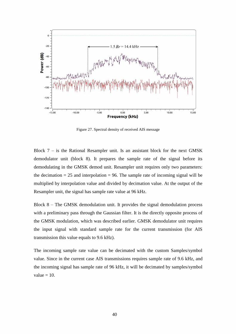
Figure 28 shows part of demodulated bit stream at the output of GMSK demodulator
unit as the binary signal. Duration of one bit in the stream equals to 1/9600 s = 104.2 us.
The example message frame is highlighted with red dashed lines.
Figure 28. Demodulated binary AIS frame signal
4.1.5 NRZI decoding units
Blocks 9 and 10 perform the NRZI decoding process.
Block 9 – The Differential Decoder unit with only parameter modulus = 2 is the
Exclusive-Or operation for every pair of neighbour bits in the stream accordingly to
NRZI decoding standard. bit
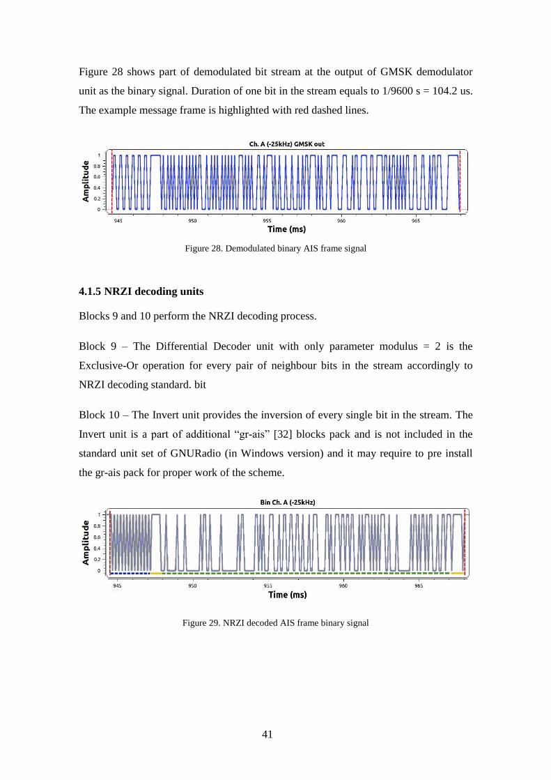
Block 10 – The Invert unit provides the inversion of every single bit in the stream. The
Invert unit is a part of additional “gr-ais” [32] blocks pack and is not included in the
standard unit set of GNURadio (in Windows version) and it may require to pre install
the gr-ais pack for proper work of the scheme.
Figure 29. NRZI decoded AIS frame binary signal

42
NRZI decoded bit sequence is shown on Figure 29 as a binary signal. The example
message data frame is highlighted with red dashed lines. It represents the actual TDMA
frame excluding the ramp-up and unused buffer fields. Other fields of TDMA frame are
underlined with the following colours: Preamble sequence – dashed blue, HDLC start
and stop flags – yellow; frame payload – dashed green. Highlighted part of a binary
signal corresponds to the following bit sequence:
“010101010101010101010101011111100010000001000010000000001011001000000
1000000000010110000000110101000111000100110011001100100010011100000110
1001110110110110001010111010101011100100001000000001011010110101100010
011011101111110”
During the processing in GNURadio scheme, the received raw signal was: optionally
saved in a file for future usage and filtered with two FIR filters for parallel signal
processing from both AIS channels. Each of them was demodulated with GMSK
demodulation unit, NZRI decoded and two result bit streams were saved as binary files
for further processing in AIS NMEA message generator, since the GNURadio provides
only the basic possibilities of the bit stream processing. All saved output files are shown
on Figure 30
Figure 30. Saved files with results of signal processing in GNURadio scheme
The ExmplRaw file contains saved received by source unit (RTL-SDR device) signals
without any modification. The recording parameters were: sample rate at 1 MHz, central
frequency at 162 MHz (no need of frequency correction), duration ~ 51s. It can be used
further as source file.
The ExmplBinaryChnlA.bin and ExmplBinaryChnlB.bin are the generated binary files,
which contain demodulated and NRZI decoded binary data received accordingly from
AIS channels A (161.975 MHz) and B (162.025 MHz). These files will be used as a
source files for further processing.

43
4.2 HDLC to AIS NMEA converter
The GNURadio scheme generated two binary files (ExmplBinaryChnlB.bin and
ExmplBinaryChnlB.bin) with data from both AIS channels. Each file represents the
solid bit stream, which contains the amount of TDMA frames with AIS data payload.
All of them have to be found and processed. For this purpose it was written a program
on C programming language, which provides a search of TDMA frames in binary file
and ensures their integrity for further processing. It also provides the full processing of
payload data from every TDMA frame, displays the most common decoded information
and generates AIS NMEA messages for storage and more detailed decoding by using
AisDecoder free software. The main structural scheme of the HDLC to AIS NMEA
converter is shown in Figure 31. Structural scheme of “DATA PROCESSING UNIT” is
shown on Figure 32. Full code of the program, as well as its working version can be
found by the link from Appendix 1. Since the program is still a prototype version, it has
no graphic interface and works in command prompt.
Figure 31. Structure scheme of program “HDLC to AIS NMEA converter”

44
Figure 32. Structural scheme of program’s DATA PROCESSING UNIT
HDLC to AIS NMEA converter starts with the main menu, which is shown on the
Figure 33. There are four different options: “exit” to exit the program, “chnl” to define
the AIS channel, which will be used during the NEMEA message generation. The “file”
command allows to define the source file, which contains the bit sequence, which has to
be processed. Command “gen” initiates the main processing stage of data – from
relevant data search in finery file to AIS NMEA message generation.
Figure 33. Program’s main menu
45
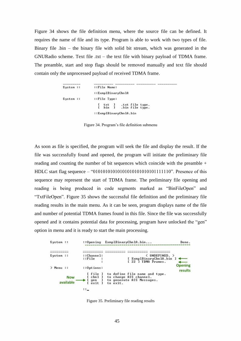
Figure 34 shows the file definition menu, where the source file can be defined. It
requires the name of file and its type. Program is able to work with two types of file.
Binary file .bin – the binary file with solid bit stream, which was generated in the
GNURadio scheme. Text file .txt – the text file with binary payload of TDMA frame.
The preamble, start and stop flags should be removed manually and text file should
contain only the unprocessed payload of received TDMA frame.
Figure 34. Program’s file definition submenu
As soon as file is specified, the program will seek the file and display the result. If the
file was successfully found and opened, the program will initiate the preliminary file
reading and counting the number of bit sequences which coincide with the preamble +
HDLC start flag sequence – “01010101010101010101010101111110”. Presence of this
sequence may represent the start of TDMA frame. The preliminary file opening and
reading is being produced in code segments marked as “BinFileOpen” and
“TxtFileOpen”. Figure 35 shows the successful file definition and the preliminary file
reading results in the main menu. As it can be seen, program displays name of the file
and number of potential TDMA frames found in this file. Since the file was successfully
opened and it contains potential data for processing, program have unlocked the “gen”
option in menu and it is ready to start the main processing.
Figure 35. Preliminary file reading results

46
Command “chnl” will initiate the AIS channel definition process. It allows to select the
AIS channel from which the signals were received. This command will open channel
definition submenu. After the channel definition the program will display the chosen
channel in main menu as it can be seen on Figure 36.
Figure 36. Program’s channel definition submenu
Channel definition process is unnecessary for main data processing. If the channel was
not specified, during the message generation the program will use the default unknown
channel sign “X”. It will not affect the generation process in the current software or the
detailed decoding process in AisDecoder software. Although, the AisDecoder will warn
about invalid channel defined.
Command “gen” will initiate the main data processing and AIS NMEA message
generation according to HDLC and NMEA standards. It will start with source file
opening and all found earlier relevant data copying to the buffer.
4.2.1 HDLC frame detection and payload copying
The main data processing can be initiated with command “gen” in main menu.
Depending of the source file type, the process starts with reopening the defined file to
copy the payload fields of all TDMA frames, which were found earlier during the first
file opening process. The copying process will end as soon as the sequence of HDLC
stop flag (01111110) appears.

47
Also the copying process has the following limitations: the maximum size of possible
payload is limited with a size of the largest possible AIS message – 1080 bits (AIS
message type 26 – Multiple Slot Binary Message can contain up to 1064 bits of data +
16 bit checksum). If the stop flag sequence appear, and the size of copied data is less
than 54 bits (first 38 bits with message type, MID and MMSI number, which present in
every message type + 16 bit checksum), the program will recognize this payload as
empty, since it contains not enough data even for its source recognizing.
If the source is a text file, the program will skip the search of TDMA frame start and
end signs, and will recognize all the binary data inside as a payload of single TDMA
frame. It will be accordingly copied for the further processing. Those processes are
being produced in the code segments “TxtFileRead” for the txt file and “BinFileRead”
for the binary file.
As a result, the program has removed all of further unnecessary bits, including the
preamble bit sequences and all of the HDLC start and stop flag sequences. Every data
payload bit sequence with its personal checksum was copied into the separate buffer
segment of the program and is ready for the further processing. The example message
data payload was stored in buffer as a following sequence:
“001000000100001000000000101100100000010000000000101100000001101010001
1100010011001100110010001001110000011010011101101101100010101110101010
111001000010000000010110101101011000100110111”
Before the further data processing, program will create the log file named
[name]_Log.doc, where [name] is the name of source file. The further data processing
steps will be done in course with every data sequence separately. Every single
processing step result will be saved in log file.
The further data processing is being performed in the program code segment named as
“Processing” and the Figure 32 represents its structural scheme.
48
4.2.2 Bit stuffing removal
According to HDLC protocol standard, the bit sequence between recently removed
HDLC flags contains necessary stuffing bits. The next step of the program is the bit
stuffing removal. The program will initiate the simple shift register and will search for
every 5 consecutive “1” bits. As soon as such a sequence was found, the program will
check the next bit: if the next bit is “0”, program will recognize it as stuffing bit and will
remove it from the data sequence. Once the program will find 6 consecutive “1” bits, it
will notify user about the appeared data corruption and will mark the current data
sequence as corrupted. The actual bit stuffing removal process is being produced in
code segment named as “Stuffing Bits”.
The data sequence without stuffing bits should contain the integer number of 8bit bytes.
This characteristic of data sequence is being checked in the small subsegment of code
named “Integrity check”. The number of bits in data sequence is being divided by 8. If
the remainder of the division equals to zero, the data sequence length is correct
according to HDLC protocol standard. Otherwise the program will recognize it as a data
corruption and will abort the processing of current data sequence with appropriate
notification.
Figure 37. Notification about successful stuffing bit removal process
Since the example data sequence contains no stuffing bits or any data corruption, the
program proceed without any additional notification (Figure 37). The bit sequence
remains the same
4.2.3 HDLC FCS control
The following HDLC frame check sequence control is the last data corruption check of
the received AIS message. Every HDLC frame contains the 16 bit frame check
sequence right after the main data sequence. It represents the standard 16 bit cyclic
redundancy check code, calculated over all the AIS data bits by using specific known
polynomial accordingly to CRC16 standard, discussed in part 3.2.2.
49
During this processing step, the last 16 bits will be removed from the data sequence and
temporarily saved in the separate memory cell as a received check sequence. The
remaining data sequence represents the relevant bits of AIS data.
The frame check sequence bits of the example message will be separated in the
following way:
“001000000100001000000000101100100000010000000000101100000001101010001
1100010011001100110010001001110000011010011101101101100010101110101010
11100100001000000001011010110” “1011000100110111”
(Green – is the remaining AIS data sequence; Red – the separated check sequence)
Afterwards the program will calculate the checksum of remaining AIS data sequence
according to CRC16 standards by using the CRC16-GENIBUS calculation algorithm.
This process will be produced in the following code segments: “REFLECT” and
“CRCCALC”. The mentioned code segments are the intellectual property of other
author [33].
As soon as the CRC16 code is calculated, it is being compared with the separately saved
received frame check sequence. If they coincide, the remaining AIS data sequence can
be considered as reliable data. Otherwise it is a sign of presence of undefined amount of
error bits inside the data sequence. Figure 38 shows, that the CRC check for example
message was correct, and the example AIS data is fully reliable.
Figure 38. Notification about successful CRC check
4.2.4 Bit-flipping
For extra data encoding, the AIS transmitter initiates the bit flipping manipulation
process before any other binary manipulation. Therefore, during the receiving process,
the AIS receiving device should initiate the process of bit flipping as a last binary
manipulation of the processed data.

50
The bit flipping manipulation represents the grouping bits by 8 into small groups and
their overturning. The first bit in group will become the last, and the last bit will become
the first one. This process is being produced in the “Bit Flipping” code segment. User
will be also notified by the program about this manipulation result as it is shown on
Figure 39.
Figure 39. Notification about successful bit flipping process
Before bit flipping the example data sequence has the following view:
“001000000100001000000000101100100000010000000000101100000001101010001
1100010011001100110010001001110000011010011101101101100010101110101010
11100100001000000001011010110”
After the bit flipping process the example data represents the following sequence:
“000001000100001000000000010011010010000000000000000011010101100001110
0010110010001100110001000100000011111001011011011011010001110101110001
11010001000010100000001101011”
The resulting data sequence contains reliable AIS message data, which can be decrypted
according to standards of AIS message structures. Every data segment with its own
meaning will be delimited with the following symbol: “|”. Segmentation of every AIS
data sequence depends of the number of AIS message (first six bits of data sequence in
decimal form represent the AIS message type). The example data sequence represents
the AIS message type 1 – first six bits are: “000001” or “1” in decimal form.
“000001|00|010000100000000001001101001000|0000|00000000|0011010101|1|000011
1000101100100011001100|010001000000111110010110110|110110100011|10101110
0|011101|00|010|0|0010100000001101011”
51
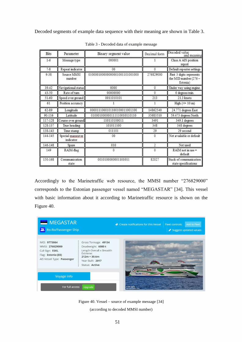
Decoded segments of example data sequence with their meaning are shown in Table 3.
Table 3 - Decoded data of example message
Accordingly to the Marinetraffic web resource, the MMSI number “276829000”
corresponds to the Estonian passenger vessel named “MEGASTAR” [34]. This vessel
with basic information about it according to Marinetraffic resource is shown on the
Figure 40.
Figure 40. Vessel – source of example message [34]
(according to decoded MMSI number)
52
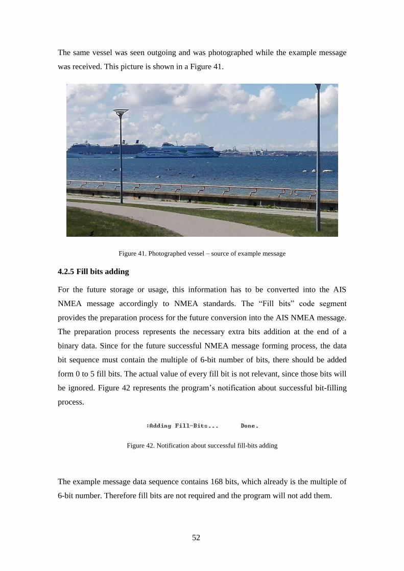
The same vessel was seen outgoing and was photographed while the example message
was received. This picture is shown in a Figure 41.
Figure 41. Photographed vessel – source of example message
4.2.5 Fill bits adding
For the future storage or usage, this information has to be converted into the AIS
NMEA message accordingly to NMEA standards. The “Fill bits” code segment
provides the preparation process for the future conversion into the AIS NMEA message.
The preparation process represents the necessary extra bits addition at the end of a
binary data. Since for the future successful NMEA message forming process, the data
bit sequence must contain the multiple of 6-bit number of bits, there should be added
form 0 to 5 fill bits. The actual value of every fill bit is not relevant, since those bits will
be ignored. Figure 42 represents the program’s notification about successful bit-filling
process.
Figure 42. Notification about successful fill-bits adding
The example message data sequence contains 168 bits, which already is the multiple of
6-bit number. Therefore fill bits are not required and the program will not add them.
53
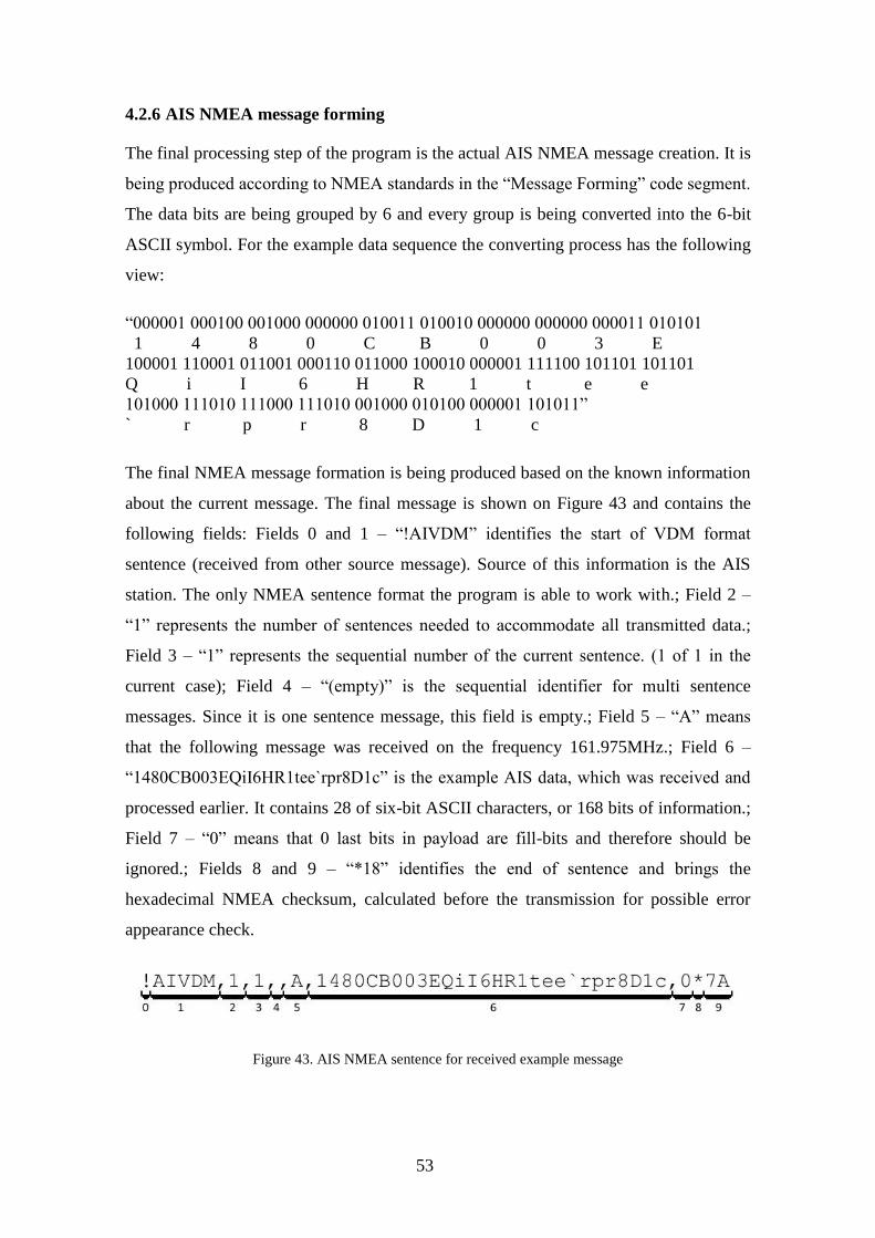
4.2.6 AIS NMEA message forming
The final processing step of the program is the actual AIS NMEA message creation. It is
being produced according to NMEA standards in the “Message Forming” code segment.
The data bits are being grouped by 6 and every group is being converted into the 6-bit
ASCII symbol. For the example data sequence the converting process has the following
view:
“000001 000100 001000 000000 010011 010010 000000 000000 000011 010101
1 4 8 0 C B 0 0 3 E
100001 110001 011001 000110 011000 100010 000001 111100 101101 101101
Q i I 6 H R 1 t e e
101000 111010 111000 111010 001000 010100 000001 101011”
` r p r 8 D 1 c
The final NMEA message formation is being produced based on the known information
about the current message. The final message is shown on Figure 43 and contains the
following fields: Fields 0 and 1 – “!AIVDM” identifies the start of VDM format
sentence (received from other source message). Source of this information is the AIS
station. The only NMEA sentence format the program is able to work with.; Field 2 –
“1” represents the number of sentences needed to accommodate all transmitted data.;
Field 3 – “1” represents the sequential number of the current sentence. (1 of 1 in the
current case); Field 4 – “(empty)” is the sequential identifier for multi sentence
messages. Since it is one sentence message, this field is empty.; Field 5 – “A” means
that the following message was received on the frequency 161.975MHz.; Field 6 –
“1480CB003EQiI6HR1tee`rpr8D1c” is the example AIS data, which was received and
processed earlier. It contains 28 of six-bit ASCII characters, or 168 bits of information.;
Field 7 – “0” means that 0 last bits in payload are fill-bits and therefore should be
ignored.; Fields 8 and 9 – “*18” identifies the end of sentence and brings the
hexadecimal NMEA checksum, calculated before the transmission for possible error
appearance check.
Figure 43. AIS NMEA sentence for received example message

54
Once the AIS NMEA message is generated, program will show the appropriate
notification with generated message and minimal decoded information about its source.
Figure 44 represents this notification, which will be displayed after the generation of
AIS NMEA message based on the example data sequence.
Figure 44. Displaying the decoded information and generated AIS NMEA message
Furthermore, the program will save the result of every processing step in log file, and
the generated message will be additionally saved in separate [name]_Msg.dat file for
storage and future use. The resulting files after processing binary file
ExmplBinaryChnlA.bin are shown on the Figure 45. Processing log file content can be
seen on the Figure 46, and Figure 47 shows the content of final data file
(ExmplBinaryChnlA_Msg.dat).
Figure 45. Files with binary data processing results, created by the program

55
Figure 46. Contents of log file about example message
Figure 47. Contents of created message (Msg) file
56
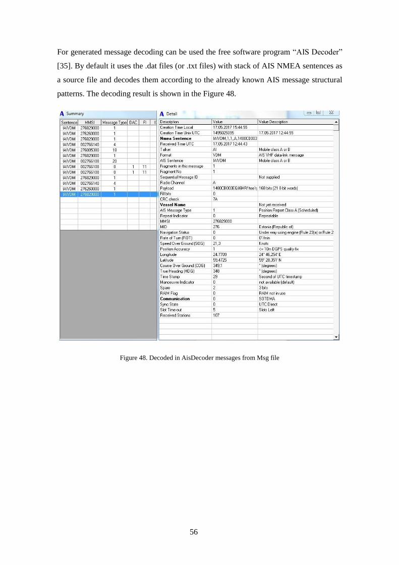
For generated message decoding can be used the free software program “AIS Decoder”
[35]. By default it uses the .dat files (or .txt files) with stack of AIS NMEA sentences as
a source file and decodes them according to the already known AIS message structural
patterns. The decoding result is shown in the Figure 48.
Figure 48. Decoded in AisDecoder messages from Msg file
57
5 AIS transmitter
Since the structure of the receiving device is already known and realized, the structure
of transmitter can be realized in reverse order. First of all, the message payload should
be supplemented with additional stuffing bits and other necessary fields according to
HDLC and TDMA protocol standards. The resultant TDMA frame should be NRZI
encoded and modulated in GMSK modulator with parameter BT = 0.5 to 0.3 and
samples per symbol parameter, which depends of the chosen carrier signal’s sample
rate: (carrier signal’s sample rate should equal to the multiplication of AIS
transmission’s sample rate (9.6kbps) and modulating samples per symbol parameter).
Afterwards the signal should be amplified and can be transmitted.
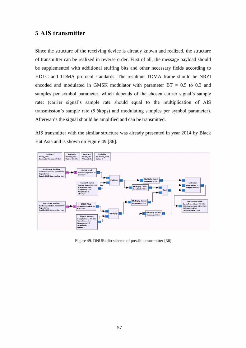
AIS transmitter with the similar structure was already presented in year 2014 by Black
Hat Asia and is shown on Figure 49 [36].
Figure 49. DNURadio scheme of possible transmitter [36]
58
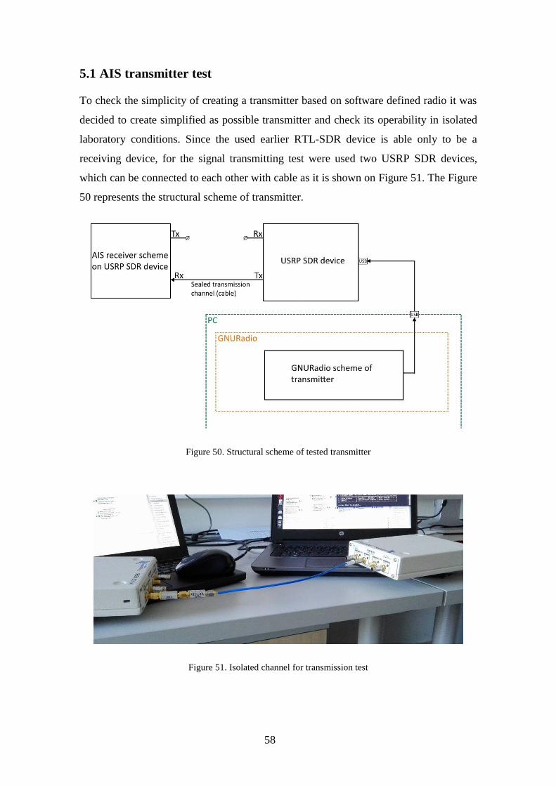
5.1 AIS transmitter test
To check the simplicity of creating a transmitter based on software defined radio it was
decided to create simplified as possible transmitter and check its operability in isolated
laboratory conditions. Since the used earlier RTL-SDR device is able only to be a
receiving device, for the signal transmitting test were used two USRP SDR devices,
which can be connected to each other with cable as it is shown on Figure 51. The Figure
50 represents the structural scheme of transmitter.
Figure 50. Structural scheme of tested transmitter
Figure 51. Isolated channel for transmission test

59
The GNURadio scheme for transmitter, which is shown on Figure 52 provides the direct
transmission of previously recorded files without any changes by using USRP SDR
device. This GNURadio scheme can be found by the link from Appendix 1.
Figure 52. GNURadio scheme for transmitter
The previously received and recorded AIS signals are being directly sent to the output
of transmitting USRP device with minimal gain. Spectrum of transmitted file is shown
on Figure 53. It contains few frames with AIS data, which are marked with red arrows.
Figure 53. Spectrum of transmitted signals

60
The transmission process is shown on Figure 54. Device on the right is transmitting
previously recorded file. Device on the left is receiving this transmission through the
isolated cable channel. Since the transmitted file was recorded earlier without any noise
filtering, the receiver is getting the full spectre of recorded noises.
Figure 54. Transmission in progress
According to the Estonian laws, the interference in the operation of the data transmitting
systems is forbidden. Therefore any unauthorized transmission on the AIS frequencies
can be done only in laboratory conditions. The transmission test was done fully in
laboratory isolated conditions by using a cable as closed channel for transmission.

61
5.2 Security aspect
Since the controlled transmission through the cable was successful, with extra
calibrations the open radio transmission can be also simply initiated by anyone using the
same devices and applications. It can cause different hacker attacks on the local AIS
communication from a simple jammer to fake vessel signals. The most possible attacks
may be:
RF spoofing,
Man-in-Water Spoofing,
Injecting into legit AIS gateways,
Frequency hopping,
CPA alerting,
Timing attack [36].
Interruption into the AIS transmissions can cause the real threat to marine navigational
abilities and accident vessel collision. The following problem was investigated in more
detail by the Black Hat Asia team in the article “AIS Exposed Understanding
Vulnerabilities & Attacks 2.0” in 2014 [36].
The possible countermeasures could be: the transmission source authentication, time
check, location check, integrity monitoring, data validity check [36]. Nevertheless it
could start with development of new AIS standards, which will provide the higher level
of security of maritime automatic identification system.

62
6 Legal aspect
Accordingly to Estonian laws, the initiating of any radio broadcasting transmission on
frequencies, which are not intended for free usage by any person might be regarded as
radio interference and may cause a pecuniary punishment or up to three years’
imprisonment.
§ 410. Causing radio interference or transmission of false or misleading messages
Causing radio interference or transmission of false or misleading messages, if a danger
to the life or health of a large number of people or to the environment is thereby caused,
is punishable by a pecuniary punishment or up to three years’ imprisonment.
Penal Code of Republic of Estonian from January 19th 2017 [37].
§ 20. Use of radio frequencies without frequency authorization
(1) The minister responsible for the area has the right, in accordance with the purposes
of use of radio frequencies, to determine the possibility to use radio frequencies without
a frequency authorization and establish the conditions for the use of radio frequencies
with regard to the specified radio frequencies and the technical requirements necessary
to avoid radio interference, ensure interoperability of equipment and ensure protection
of the public from the harmful effect of electromagnetic fields.
§ 22. Incorrect or misleading message and information subject to radio communication
secrecy
(1) It is prohibited to send, by means of radio communication, incorrect or misleading
messages which may prejudice the safety of aircraft, ships or vehicles on land or of
persons or the functioning of the activities of any rescue service agency.
Electronic Communications Act of Republic of Estonia from 01.04.2017 [38].
63
7 Financial aspect
There are many different specialized AIS stations. All of them are able to scan both AIS
channels with good sensitivity, receive all messages and decode them according to the
current AIS standards. Moreover those receivers often provide the simultaneous scan of
both AIS channels in parallel. More expensive devices can also provide the visual
representation of all received data. Those AIS stations usually have the price below
500$ USD, and they are unable to transmit the data.
In addition to receiving the most professional transponders are able to transmit their
own navigational data, but it also require the presence of other specialized devices as
GPS. Those devices are known as Class A and Class B transponders. Class A
transponders have the widest range of possibilities, but require the large set of other
devices to co-operate with. Therefore they are suitable for the most equipped vessels.
Class B devices have fewer features but also require the presence of smaller set of other
devices, and therefore they can be used on the smaller and less equipped vessels.
Most AIS communications are performed by purpose-built hardware systems. There are
several types:
Class A Transponders >$2000 – Full implementation that can transmit a vessel´s
data on either AIS channel and receive on both channels simultaneously.
Class B Transponders ~$1000 – For non-compulsorily fitted vessels requiring to
have an inexpensive AIS system - same VHF specs but fewer features and
capabilities.
Dual Channel Receivers ~$400 – Receives AIS on both channels simultaneously
- usually providing a NMEA data output. No transmission.
Scanning Receivers ~$200 – Receives AIS on both one of the two channels at a
time (but scans between them) - usually providing a NMEA data output. No
transmission [39].
All prices are valid at May 2017.

64
During this work was recreated the based on RTL-SDR device AIS receiver with
abilities of dual channel receiver with some disadvantages: The main disadvantage is
that the receiver is not literally real time receiver. It requires separate recording of the
incoming signals with demodulation and preliminary NRZI decoding by using
GNURadio receiver scheme, and main binary data processing with NMEA message
generation a minimal data decoding in HDLC to AIS NMEA converter. In addition, for
detailed data decoding can be used free software program AisDecoder. Although, the
full cycle of decoding does not take more than a few minutes, and the cost of this
handmade receiver is much lower than the specialized device.
The following parts are needed to assemble the AIS receiver described in this work:
Computer with Windows operating system
Bootable USB with Ubuntu versoin of GNURadio. (Optional, but recommended
since the GNURadio versions for Windows may not have the necessary extra
components.) [31]
HDLC to AIS NMEA converter 3.3.2
Free software “AisDecoder” [35]
RTL2832U + R820T – $8 – 20
Total cost: < $20 at May 2017. All necessary software can be found in the Appendix 1.
65
8 Summary
The main goal of this thesis was the implementation of open marine Automatic
Identification System (AIS) on Software Defined Radio, which will be able to use a
variety of SDR devices. AIS is an ITU (International Telecommunication Union) and
IMO (International Maritime Organization) standardized, automatic and autonomous
tracking system which provides vessel navigational and other safety-related information
automatically to appropriately equipped shore stations, other ships, and aircrafts.
In the second section, this thesis covers main characteristics of AIS transmission: 25
kHz wide frequency channels reserved for AIS transmissions at 161.975 MHz and
162.025MHz, 9.6 kbps transmission bitrate and enumeration of standards, used in AIS.
The third section contains detailed description of all signal reception theoretical
fundamentals and AIS standards. It includes the used for transmitting GMSK (Gaussian
Minimum Shift Keying) modulation method, the Time Division Multiple Access
method, which provides the simultaneous access of multiple different AIS stations to
one transmission channel, HDLC (High-level Data Link Control) message frame
forming method, NZRI encoding and decoding methods, and NMEA message forming
standards.
The fourth section describes the implemented AIS receiver, which performs the real
time signal reception using SDR device. The software assembled part of receiver allows
to use different hardware devices as well as input data files. For those purposes it was
used the freeware GNURadio environment. It allows to configure the external device
and provides the entire signal processing including demodulation. Main functionality
was successfully implemented in GNURadio scheme, which includes frequency
correction, reception channel filtering, bandwidth resampling, GMSK demodulation,
NRZI decoding, message preamble correlation and binary data storage for further
processing. The especially developed software “HDLC to AIS NMEA converter”
performs the ship transmitted data frame detection in the presence of background noise.
The main core of this C language written program processes detected data frames in
order to eliminate frame bit stuffing, provides bit flipping and filling manipulations,
multiple frame integrity checks and displays the most common information with
resulting data storage option.
66
The simplicity of SDR based AIS signal transmitter, discussed in fifth part, has
demonstrated the insecurity of maritime Automatic Identification System and its
vulnerability to potential hacker attacks, which can cause a serious damage to shipping
safety. In confirmation of implemented SDR based transmitter operability the successful
transmission tests was performed in isolated laboratory conditions. However, any radio
broadcasting transmissions are being regulated by legal system of Republic of Estonia.
All created software is available for free use.

67
References
[1] "regulations", Siitech.com, 2017. [Online]. Available:
http://siitech.com/AIS_Technology/regulations.htm. [Accessed: 21- May- 2017]
[2] Technical characteristics for an automatic identification system using time division
multiple access in the VHF maritime mobile frequency band, 1st ed. Geneva:
International Telecommunication Union, 2014. [Online]. Available:
http://www.itu.int/dms_pubrec/itu-r/rec/m/R-REC-M.1371-5-201402-I!!PDF-E.pdf
[Accessed: 20- May- 2017]
[3] "AIS Requirements", Navcen.uscg.gov, 2017. [Online]. Available:
https://www.navcen.uscg.gov/?pageName=AISRequirementsRev.
[Accessed: 20- May- 2017]
[4] "What is the Automatic Identification System (AIS)?", MarineTraffic Help, 2017.
[Online]. Available: https://help.marinetraffic.com/hc/en-us/articles/204581828-What-
is-the-Automatic-Identification-System-AIS-. [Accessed: 20- May- 2017]
[5] "Automatic identification system", En.wikipedia.org, 2017. [Online]. Available:
https://en.wikipedia.org/wiki/Automatic_identification_system.
[Accessed: 20- May- 2017]
[6] "Частотная манипуляция", Ru.wikipedia.org, 2017. [Online]. Available:
https://ru.wikipedia.org/wiki/Частотная_манипуляция. [Accessed: 20- May- 2017]
[7] N. Mandayam and D. Wu, Wireless Communication Technologies, 1st ed. Rutgers
University – Dept. of Electrical and Computer Engineering, 2002, p. 2.
[8] "Cite a Website - Cite This For Me", Cdt21.com, 2017. [Online].
Available: http://www.cdt21.com/resources/Modulation/images/img/msk01.gif.
[Accessed: 20- May- 2017]
[9] "GMSK", Dsplib.ru, 2017. [Online]. Available:
http://www.dsplib.ru/content/gmsk/gmsk.html. [Accessed: 20- May- 2017]
[10] F. Kostedt and J. Kemerling, Practical GMSK Data Transmission, 1st ed. Winston-
Salem: MXCOM, INC., 1998, p. 3.
[11] T. Turletti, GMSK in a nutshell, 1st ed. Cambridge, Massachusetts, 1996, pp. 2, 4.
[12] "Time-division multiple access", En.wikipedia.org, 2017. [Online]. Available:
https://en.wikipedia.org/wiki/Time-division_multiple_access#cite_note-Zander-1.
[Accessed: 20- May- 2017]
[13] "CanX-6 - eoPortal Directory - Satellite Missions", Directory.eoportal.org, 2017.
68
[Online]. Available: https://directory.eoportal.org/web/eoportal/satellite-missions/c-
missions/canx-6. [Accessed: 20- May- 2017]
[14] AIS TDMA Access schemes, 1st ed. All About AIS, 2012, pp. 3-6.
[Online]. Available:
http://www.allaboutais.com/jdownloads/Access%20schemes%20technical%20downloa
ds/ais_tdma_access_schemes.pdf [Accessed: 20- May- 2017].
[15] K. Mathapo, A SOFTWARE-DEFINED RADIO IMPLEMENTATION OF
MARITIME AIS, 1st ed. Stellenbosch, Western Cape, (SA): University of Stellenbosch,
2017, p. 21. [Online]. Available: http://scholar.sun.ac.za/handle/10019.1/2215
[Accessed: 20- May- 2017]
[16] "Understanding Optical Communications:Optical Communication Systems",
Imedea.uib-csic.es, 2017. [Online]. Available:
http://imedea.uib-csic.es/~salvador/docencia/coms_optiques/addicional/ibm/ch07/07-
03.html. [Accessed: 20- May- 2017]
[17] "High-Level Data Link Control", En.wikipedia.org, 2017. [Online]. Available:
https://en.wikipedia.org/wiki/High-Level_Data_Link_Control.
[Accessed: 20- May- 2017]
[18] INTERNATIONAL STANDARD ISO/IEC 13239: Information technology —
Telecommunications and information exchange between systems — High-level data link
control (HDLC) procedures, 1st ed. International Organization for Standardization,
2002. [Online]. Available:
https://webstore.iec.ch/preview/info_isoiec13239%7Bed3.0%7Den.pdf
[Accessed: 20- May- 2017]
[19] "Catalogue of parametrised CRC algorithms", Reveng.sourceforge.net, 2017.
[Online]. Available: http://reveng.sourceforge.net/crc-catalogue/16.htm.
[Accessed: 20- May- 2017]
[20] NMEA 0183 Standard For Interfacing Marine Electronic Devices, 1st ed. National
Marine Electronics Association, 2002, pp. 12, 77-78.
[21] NMEA 0183 All Identifiers, Manufacturer Mnemonic Codes, and Sentence
Formatters List, 1st ed. National Marine Electronics Association, 2013, p. 20.
[22] "AIS Messages", Navcen.uscg.gov, 2017. [Online]. Available:
https://www.navcen.uscg.gov/?pageName=AISMessages. [Accessed: 20- May- 2017]
[23] "Class A AIS Position Report (Messages 1, 2, and 3)", Navcen.uscg.gov, 2017.
[Online]. Available: https://www.navcen.uscg.gov/?pageName=AISMessagesA.
[Accessed: 20- May- 2017]
[24] "What is Software Defined Radio". [Online]. Available:
http://www.wirelessinnovation.org/assets/documents/SoftwareDefinedRadio.pdf.
[Accessed: 20- May- 2017]
69
[25] "Software-defined radio", En.wikipedia.org, 2017. [Online]. Available:
https://en.wikipedia.org/wiki/Software-defined_radio. [Accessed: 20- May- 2017]
[26] "About RTL-SDR", rtl-sdr.com, 2017. [Online]. Available: http://www.rtl-
sdr.com/about-rtl-sdr/. [Accessed: 20- May- 2017]
[27] "Motivations Quad-band GSM GPS Bluetooth b…. GPRS EDGE WCDMA LTE -
ppt download", Slideplayer.com, 2017. [Online]. Available:
http://slideplayer.com/slide/3753910/. [Accessed: 20- May- 2017]
[28] "Roundup of Software Defined Radios", rtl-sdr.com, 2017. [Online]. Available:
http://www.rtl-sdr.com/roundup-software-defined-radios/. [Accessed: 20- May- 2017]
[29] "USRP B210 USB Software Defined Radio (SDR) - Ettus Research", Ettus.com,
2017. [Online]. Available: https://www.ettus.com/product/details/UB210-KIT.
[Accessed: 20- May- 2017]
[30] "HDSDR Homepage", Hdsdr.de, 2017. [Online]. Available: http://www.hdsdr.de/.
[Accessed: 20- May- 2017]
[31] "GNU Radio Live SDR Environment - GNU Radio", Wiki.gnuradio.org, 2017.
[Online]. Available:
https://wiki.gnuradio.org/index.php/GNU_Radio_Live_SDR_Environment.
[Accessed: 20- May- 2017]
[32] "bistromath/gr-ais", GitHub, 2017. [Online]. Available:
https://github.com/bistromath/gr-ais. [Accessed: 20- May- 2017]
[33] "Cite a Website - Cite This For Me", Zorc.breitbandkatze.de, 2017. [Online].
Available: http://www.zorc.breitbandkatze.de/crctester.c. [Accessed: 20- May- 2017]
[34] "MEGASTAR Ro-Ro/Passenger Ship", Marinetraffic, 2017. [Online]. Available:
https://www.marinetraffic.com/en/ais/details/ships/shipid:4691590/mmsi:276829000/im
o:9773064/vessel:MEGASTAR. [Accessed: 20- May- 2017]
[35] N. Arundale, "Ais Decoder", Arundale.com, 2017. [Online]. Available:
http://arundale.com/docs/ais/ais_decoder.html. [Accessed: 20- May- 2017]
[36] K. Wilhoit and A. Pasta, AIS Exposed Understanding Vulnerabilities & Attacks
2.0, 1st ed. Singapore: black hat Asia, 2014, pp. 23-24, 42.
[37] "Penal Code – Riigi Teataja", Riigiteataja.ee, 2017. [Online]. Available:
https://www.riigiteataja.ee/en/eli/519012017002/consolide. [Accessed: 20- May- 2017]
[38] "Electronic Communications Act – Riigi Teataja", Riigiteataja.ee, 2017. [Online].
Available: https://www.riigiteataja.ee/en/eli/527032017001/consolide.
[Accessed: 20- May- 2017]
[39] "AIS - Automatic Identification System - Information Page", Bosunsmate.org,
2017. [Online]. Available: http://www.bosunsmate.org/ais/. [Accessed: 20- May- 2017]

70
Appendix 1 – Implemented software
Two copies of the code of “HDLC to AIS NMEA converter” program, the compiled
program itself, as well as implemented GNURadio schemes of AIS receiver and AIS
transmitter can be found by the following link:
https://www.dropbox.com/sh/6tevk7zpxoib7dx/AAAWYC6ByUGmLa7O3tuugh3ta?dl=0
This link contents is shown on the Figure and it includes the following files:
AIS_Receiver_GNURadio_scheme.grc – GNURadio scheme of AIS receiver.
AIS_Transmitter_GNURadio_scheme.grc – GNURadio scheme of AIS transmitter.
HDLC to AIS NMEA.V3.3.2.exe – compiled and working copy of the program.
HDLC to AIS NMEA.V3.3.2.c – code of the program in .c file.
HDLCtoAISNMEA_program_code.docx – code of the program in .docx file.
Figure 55. Appendix 1 link contents