software engineering 1mycsvtunotes.weebly.com/uploads/1/0/1/7/10174835/... · software engineering...
TRANSCRIPT
Software Engineering
SE Notes Mr. D. K. Bhawnani, Lect (CSE) BIT
1
Unit 3
Design concepts and principles
Software Design
1. Software design deals with transforming the customer requirements, as described by the SRS document, into a form that is
implementable using a programming language.
2. For a design to be easily implementable in a conventional programming language, the following items must be designed during
the design phase.
• Different modules required to implement the design solution.
• Control relationships among the identified modules. The relationship is also known as the call relationship or invocation
relationship among modules.
• Interface among different modules. The interface among different modules identifies the exact data items exchanged
among the modules.
• Data structures of the individual modules.
• Algorithms required to implement the individual modules.
3. Thus, the objective of the design phase is to take the SRS document as the input and produce the above mentioned documents
before completion of the design phase.
4. We can broadly classified the design activities into two important parts:
a) Preliminary (or High level) Design
• High level design means identification of different modules, the control relationships and the definitions of the
interfaces among them.
• The outcome of the high level design is called the program structure or software architecture.
• Many different types of notations have been used to represent a high level design. A popular way is to use a tree
like diagram called the structure chart to represent the control hierarchy in a high level design.
b) Detailed Design
• During detailed design, the data structure and the algorithms of different modules are designed.
• The outcome of the detailed design stage is usually known as the module specification document.
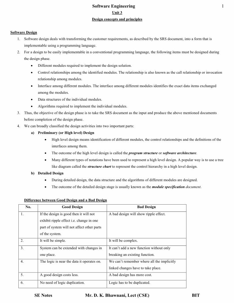
Difference between Good Design and a Bad Design
No. Good Design Bad Design
1. If the design is good then it will not
exhibit ripple effect i.e. change in one
part of system will not affect other parts
of the system.
A bad design will show ripple effect.
2. It will be simple. It will be complex.
3. System can be extended with changes in
one place.
It can’t add a new function without only
breaking an existing function.
4. The logic is near the data it operates on. We can’t remember where all the implicitly
linked changes have to take place.
5. A good design costs less. A bad design has more cost.
6. No need of logic duplication. Logic has to be duplicated.

Software Engineering
SE Notes Mr. D. K. Bhawnani, Lect (CSE) BIT
2
Design Model
The design principles and concepts establish a foundation for the creation of the design model that encompasses representation of data,
architecture, interface and components. Like the analysis model before it, each of these design representations is tied to the others, and all
can be traced back to software requirements.
The Entity-Relationship Diagrams (ERD), the Data Flow Diagrams (DFD), the State Transition
Diagrams (STD) and the Data Dictionaries (DD) that are constructed during the requirements phase are directly mapped on to the
corresponding design model as shown below.
1. Data Design – It transforms the information domain model created during analysis into the data structures that will be required to
implement the software. The data objects (or entities) and the relationships defined in ER diagram and the detailed data content
depicted in the Data Dictionary provide the basis for the data design activity. Detailed data design occurs as each software
component is designed.
2. Architectural Design – It defines the relationship between major structural elements of the software, the “design patterns” that
can be used to achieve the requirements that have been defined for the system. This design representation forms the framework of
a computer based system. It can be derived from the system specification, the analysis model and the interaction of subsystems
defined within the analysis model.
3. Interface Design – It describes how the software communicates within itself, with systems that interoperate with it and with
humans who use it. An interface implies a flow of information and a specific type of behavior. Therefore, data and control flow
diagrams provide much of the information required for interface design.
4. Component Level Design – It transforms structural elements of the software architecture into a procedural description of
software components. Information obtained from ER-Diagrams, Data Flow diagrams or STDs, serves as the basis for component
design.
Software Engineering
SE Notes Mr. D. K. Bhawnani, Lect (CSE) BIT
3
During design we make decisions that will ultimately affect the success of software construction and, as important, the ease with which
software can be maintained. But why is design so important?
The importance of software design can be stated with a single word – Quality. Design is the place where quality is fostered in
software engineering. Design provides us with representations of software that can be accessed for quality. Design is the only way that we
can accurately translate a customer’s requirements into a finished software product or system. Software design serves as the foundation for
all the software engineering and software support activities that follow. Without design, we risk building an unstable system – one that will
fail when small changes are made; one that may be difficult to test; one whose quality cannot be accessed until late in the software process,
when time is short and many dollars have already been spent.
Design Process
Software design is an iterative process through which requirements are translated into a “blueprint” for constructing the software. Initially,
the blueprint depicts a holistic view of software i.e., the design is represented at a high level of abstraction – a level that can be directly
traced to the specific system objectives. As design iterations occur, subsequent refinement leads to design representations at much lower
levels of abstraction.
McGlaughlin suggests 3 characteristics that serve as a guide for evaluation of a good design:
1. The design must implement all of the explicit requirements contained in the analysis model and it must accommodate all of the
implicit requirements desired by the customer.
2. The design must be readable, understandable guide for those who generate code and for those who test and support the software.
3. The design should provide a complete picture of the software, addressing all data, functional and behavioral domains.
Each of these characteristics is actually a goal of the design process.
Quality Guidelines that lead to a good design
1. A design should exhibit an architecture that
a) Has been created using recognizable architectural styles or patterns;
b) Is composed of components that exhibit good design characteristics, and
c) Can be implemented in an evolutionary fashion, thereby facilitating implementation and testing.
2. A design should be modular; that is, the software should be logically partitioned into elements or subsystems.
3. A design should contain distinct representations of data, architecture, interfaces, and components.
4. A design should lead to data structures that are appropriate for the classes to be implemented and are drawn from recognizable
data patterns.
5. A design should lead to the components that exhibit independent functional characteristics.
6. A design should lead to interfaces that reduce the complexity of connections between components and with the external
environment.
7. A design should be derived using a repeatable method that is driven by information obtained during software requirements
analysis.
8. A design should be represented using a notation that effectively communicates its meaning.
Design Principles
Software design is both a process and a model. The ‘design process’ is a sequence of steps that enable the designer to describe all aspects
of the software to be built. The ‘design model’ is however, an equivalent of an architect’s plan for a house. It begins by representing the
totality of the thing to be built (e.g. a 3D house) and slowly refining it into more details. Similarly, the design model that is created for
software provides a variety of different views of the computer software.

Software Engineering
SE Notes Mr. D. K. Bhawnani, Lect (CSE) BIT
4
Davis – Design Principles
1. The design process should not suffer from “tunnel vision”. A good designer should consider alternative approaches, judging each
based on the requirements of the problem, and the resources available to do the job.
2. The design should be traceable to the analysis model. It is necessary to have a means for tracking how requirements have been
satisfied by the design model.
3. The designer should not reinvent the wheel, i.e., Use the set of design patterns, already encountered so that new patterns are not
reinvented. Time is short and resources are limited. Design time should be invested in representing truly new ideas and integrating
those patterns that already exist.
4. The design should “minimize the intellectual distance” between the software and the problem as it exists in the real world i.e., the
structure of the software design should mimic the structure of the problem domain.
5. The design should exhibit uniformity and integration. A design is uniform if it appears that one person developed the entire thing.
Rules of style and format should be defined for a design team before design work begins. A design is integrated if care is taken in
defining interfaces between design components.
6. The design should be structured to accommodate change.
7. The design should be structured to degrade gently, even when aberrant data, events or operating conditions are encountered. Well
designed software should never “bomb”. It should be designed to accommodate unusual circumstances and if it must terminate
processing, do so in a graceful manner.
8. Design is not coding, coding is not design.
9. The design should be assessed for quality as it is being created, not after the fact.
10. The design should be reviewed to minimize conceptual (semantic) errors.
Design Concepts
There are 9 design concepts that we must study:
1. Abstraction
2. Refinement
3. Modularity
4. Software Architecture
5. Control Hierarchy
6. Structural Partitioning
7. Data Structure
8. Software Procedure
9. Information Hiding
1. Abstraction
a) When we consider a modular solution to any problem, many levels of abstraction can be posed. At the highest level of
abstraction, a solution is stated in broad terms using the language of the problem environment. At lower levels of abstraction, a
more procedural orientation is taken. Problem-oriented terminology is coupled with implementation – oriented terminology in an
effort to state a solution. Finally, at the lowest level of abstraction, the solution is stated in a manner that can be directly
implemented.
b) Each step in the software process is a refinement in the level of abstraction of the software solution. During system engineering,
software is allocated as an element of a computer-based system. During software requirements analysis, the software solution is
stated in terms "that are familiar in the problem environment." As we move through the design process, the level of abstraction is
reduced. Finally, the lowest level of abstraction is reached when source code is generated.

Software Engineering
SE Notes Mr. D. K. Bhawnani, Lect (CSE) BIT
5
c) As we move through different levels of abstraction, we work to create procedural and data abstractions. A procedural abstraction
is a named sequence of instructions that has a specific and limited function. An example of a procedural abstraction would be the
word open for a door. Open implies a long sequence of procedural steps (e.g., walk to the door, reach out and grasp knob, turn
knob and pull door, step away from moving door, etc.).
d) A data abstraction is a named collection of data that describes a data object. In the context of the procedural abstraction open, we
can define a data abstraction called door. Like any data object, the data abstraction for door would encompass a set of attributes
that describe the door (e.g., door type, swing direction, opening mechanism, weight, dimensions). It follows that the procedural
abstraction open would make use of information contained in the attributes of the data abstraction door.
e) Many modern programming languages provide mechanisms for creating abstract data types. For example, the Ada package is a
programming language mechanism that provides support for both data and procedural abstraction. The original abstract data type
is used as a template or generic data structure from which other data structures can be instantiated.
f) Control abstraction is the third form of abstraction used in software design. Like procedural and data abstraction, control
abstraction implies a program control mechanism without specifying internal details. An example of a control abstraction is the
synchronization semaphore used to coordinate activities in an operating system.
2. Refinement
a) Stepwise refinement is a top-down design strategy originally proposed by Niklaus Wirth. A program is developed by successively
refining levels of procedural detail. A hierarchy is developed by decomposing a macroscopic statement of function (a procedural
abstraction) in a stepwise fashion until programming language statements are reached.
b) Refinement is actually a process of elaboration. We begin with a statement of function (or description of information) that is
defined at a high level of abstraction. That is, the statement describes function or information conceptually but provides no
information about the internal workings of the function or the internal structure of the information. Refinement causes the
designer to elaborate on the original statement, providing more and more detail as each successive refinement (elaboration)
occurs.
c) Abstraction and refinement are complementary concepts. Abstraction enables a designer to specify procedure and data and yet
suppress low-level details. Refinement helps the designer to reveal low-level details as design progresses. Both concepts aid the
designer in creating a complete design model as the design evolves.
3. Modularity
a) It has been stated that "modularity is the single attribute of software that allows a program to be intellectually manageable".
Monolithic software (i.e., a large program composed of a single module) cannot be easily grasped. The number of control paths,
span of reference, number of variables, and overall complexity would make understanding close to impossible.
b) Let C(x) be a function that defines the perceived complexity of a problem x, and
E(x) be a function that defines the effort (in time) required to solve a problem x.
For two problems, p1 and p2, if C(p1) > C(p2)
it follows that E(p1) > E(p2)
i.e., it does take more time to solve a difficult problem.
Also, from experimentation it has been found that C(p1 + p2) > C(p1) + C(p2)
i.e., the perceived complexity of a problem that combines p1 and p2 is greater than the perceived complexity when each problem
is considered separately. So,
E(p1 + p2) > E(p1) + E(p2)
This leads to a "divide and conquer" conclusion—i.e., it is easier to solve a complex problem when you break it into manageable
pieces.
Software Engineering
SE Notes Mr. D. K. Bhawnani, Lect (CSE) BIT
6
i.e., if we subdivide software indefinitely, the effort required to develop it will become negligibly small! Unfortunately, other
forces come into play, causing this conclusion to be (sadly) invalid.
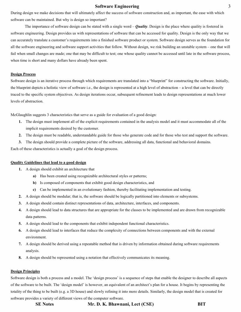
c) Consider the following graph
Fig Total cost for Efforts curves
i.e., the effort (cost) required to develop an individual software module does decrease as the total number of modules increases,
(cost/module decreases as the number of modules increases). Given the same set of requirements, more modules means smaller
individual size. However, as the number of modules grows, the effort (cost) associated with integrating the module also grows.
These characteristics lead to a total cost or effort curve as shown in fig above. There is a number, M, of modules that would result
in minimum development cost but we do not have the necessary sophistication to predict M with assurance. The curves above do
provide a useful guidance when modularity is considered. We should modularize but care should be taken to stay in the vicinity of
M. Under-modularity or over-modularity should be avoided.
4. Software Architecture
a) It covers the overall structure of the software and the ways in which that structure provides conceptual integrity for a system. So,
architecture is the hierarchical structure of program components (modules), the manner in which these components interact and
the structure of data that are used by the components.
b) An architectural design can be represented using any of the 5 – models given below:
• Structural Models – They represent architecture as an organized collection of program components.
• Framework Models – They increase the level of design abstraction by attempting to identify repeatable architectural
design frameworks.
• Dynamic Models – They address the behavioral aspects of the program architecture (states).
• Process Models – They focus on the design of the business or technical process that the system must accommodate.
• Functional Models – They can be used to represent the functional hierarchy of a system.
c) A number of different architectural description languages (ADLs) have been developed to represent these models.
Software Engineering
SE Notes Mr. D. K. Bhawnani, Lect (CSE) BIT
7
5. Control Hierarchy
a) It is also called as program structure.
b) It represents the organization of program components (modules) and implies a hierarchy of control.
c) It does not represent procedural aspects of software such as sequence of processes, occurrence or order of decisions or repetitions
of operations nor is it necessarily applicable to all architectural styles.
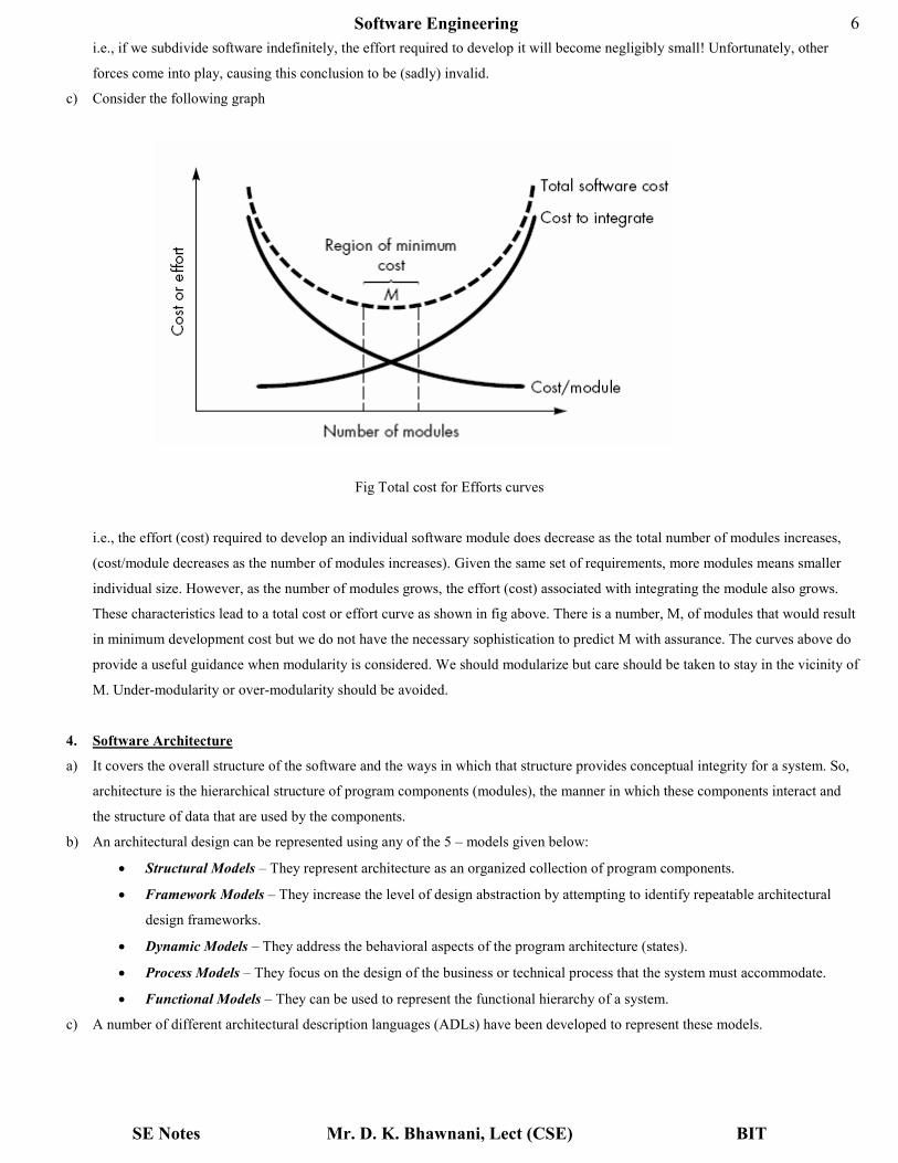
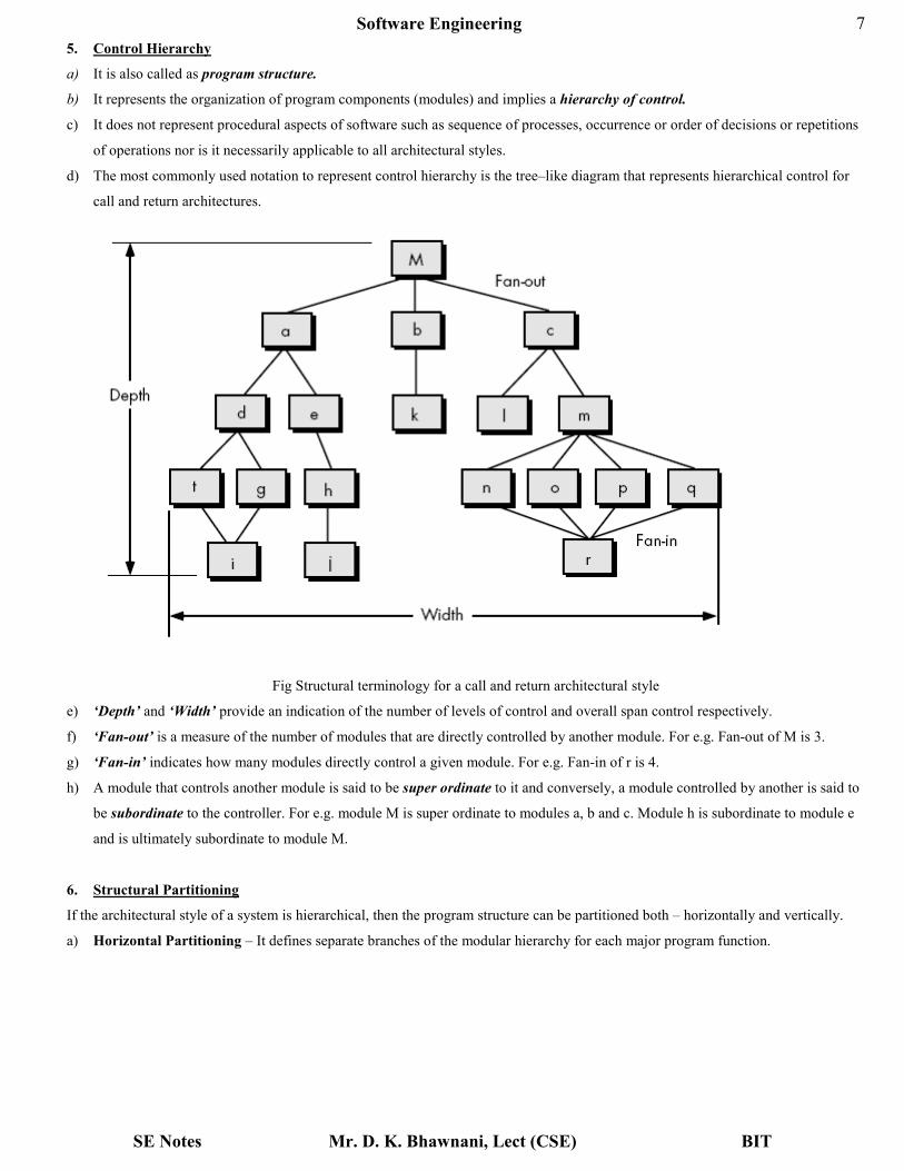
d) The most commonly used notation to represent control hierarchy is the tree–like diagram that represents hierarchical control for
call and return architectures.
Fig Structural terminology for a call and return architectural style
e) ‘Depth’ and ‘Width’ provide an indication of the number of levels of control and overall span control respectively.
f) ‘Fan-out’ is a measure of the number of modules that are directly controlled by another module. For e.g. Fan-out of M is 3.
g) ‘Fan-in’ indicates how many modules directly control a given module. For e.g. Fan-in of r is 4.
h) A module that controls another module is said to be super ordinate to it and conversely, a module controlled by another is said to
be subordinate to the controller. For e.g. module M is super ordinate to modules a, b and c. Module h is subordinate to module e
and is ultimately subordinate to module M.
6. Structural Partitioning
If the architectural style of a system is hierarchical, then the program structure can be partitioned both – horizontally and vertically.
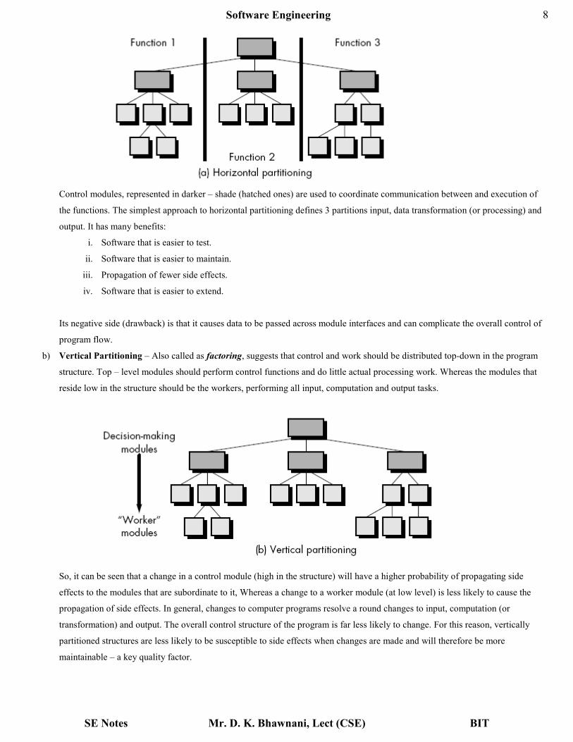
a) Horizontal Partitioning – It defines separate branches of the modular hierarchy for each major program function.
Software Engineering
SE Notes Mr. D. K. Bhawnani, Lect (CSE) BIT
8
Control modules, represented in darker – shade (hatched ones) are used to coordinate communication between and execution of
the functions. The simplest approach to horizontal partitioning defines 3 partitions input, data transformation (or processing) and
output. It has many benefits:
i. Software that is easier to test.
ii. Software that is easier to maintain.
iii. Propagation of fewer side effects.
iv. Software that is easier to extend.
Its negative side (drawback) is that it causes data to be passed across module interfaces and can complicate the overall control of
program flow.
b) Vertical Partitioning – Also called as factoring, suggests that control and work should be distributed top-down in the program
structure. Top – level modules should perform control functions and do little actual processing work. Whereas the modules that
reside low in the structure should be the workers, performing all input, computation and output tasks.
So, it can be seen that a change in a control module (high in the structure) will have a higher probability of propagating side
effects to the modules that are subordinate to it, Whereas a change to a worker module (at low level) is less likely to cause the
propagation of side effects. In general, changes to computer programs resolve a round changes to input, computation (or
transformation) and output. The overall control structure of the program is far less likely to change. For this reason, vertically
partitioned structures are less likely to be susceptible to side effects when changes are made and will therefore be more
maintainable – a key quality factor.
Software Engineering
SE Notes Mr. D. K. Bhawnani, Lect (CSE) BIT
9
7. Data Structure
a) Data structure is a representation of the logical relationship among individual elements of data.
b) Data structure dictates the organization, methods of access, degree of associativity and processing alternatives for information.
c) It may be a scalar item (or a variable), a sequential vector (array) or a linked list.
d) Note that data structures like program structures can be represented at different levels of abstraction.
8. Software Procedure
a) It focuses on the processing details of each module individually.
b) Procedures must provide a precise specification of processing, including sequence of events, exact decision points, repetitive
operations and even data organization and structure.
c) A procedural representation of software is layered i.e., we will have procedure for super ordinate modules first and then for
subordinate modules.
9. Information Hiding
a) It suggests that the modules should be specified and designed so that information (procedure and data) contained within a module
is not accessible to other modules that have no need for such information.
b) Hiding implies that effective modularity can be achieved by defining a set of independent modules that communicate with one
another only that information necessary to achieve software function.
c) Abstraction helps to define the procedural entities that make up the software. Hiding defines and enforces access constraints to
both procedural detail within a module and any local data structure used by the module.
Design documentation
1. The Design Specification addresses different aspects of the design model and is completed as the designer refines his
representation of the software. First, the overall scope of the design effort is described. Much of the information presented here is
derived from the System Specification and the analysis model (Software Requirements Specification).
2. Next, the data design is specified. Database structure, any external file structures, internal data structures, and a cross reference
that connects data objects to specific files are all defined.
3. The architectural design indicates how the program architecture has been derived from the analysis model. In addition, structure
charts are used to represent the module hierarchy (if applicable).
4. The design of external and internal program interfaces is represented and a detailed design of the human/machine interface is
described. In some cases, a detailed prototype of a GUI may be represented.
5. Components—separately addressable elements of software such as subroutines, functions, or procedures—are initially described
with an English-language processing narrative. The processing narrative explains the procedural function of a component
(module). Later, a procedural design tool is used to translate the narrative into a structured description.
6. The Design Specification contains a requirements cross reference. The purpose of this cross reference (usually represented as a
simple matrix) is (a) to establish that all requirements are satisfied by the software design and (b) to indicate which components
are critical to the implementation of specific requirements.
7. The first stage in the development of test documentation is also contained in the design document. Once program structure and
interfaces have been established, we can develop guidelines for testing of individual modules and integration of the entire
package. In some cases, a detailed specification of test procedures occurs in parallel with design. In such cases, this section may
be deleted from the Design Specification.
8. Design constraints, such as physical memory limitations or the necessity for a specialized external interface, may dictate special
requirements for assembling or packaging of software. Special considerations caused by the necessity for program overlay, virtual

Software Engineering
SE Notes Mr. D. K. Bhawnani, Lect (CSE) BIT
10
memory management, high-speed processing, or other factors may cause modification in design derived from information flow or
structure. In addition, this section describes the approach that will be used to transfer software to a customer site.
9. The final section of the Design Specification contains supplementary data. Algorithm descriptions, alternative procedures, tabular
data, excerpts from other documents, and other relevant information are presented as a special note or as a separate appendix. It
may be advisable to develop a Preliminary Operations/Installation Manual and include it as an appendix to the design
document.
Modular Design
Cohesion
Cohesion is the measure of strength of the association of elements within a module. Modules whose elements are strongly and genuinely
related to each other are desired. A module should be highly cohesive.
Types of Cohesion
There are 7 types of cohesion in a module
1. Coincidental Cohesion – A module has coincidental cohesion if its elements have no meaningful relationship to one another. It
happens when a module is created by grouping unrelated instructions that appear repeatedly in other modules.
2. Logical Cohesion – A logically cohesive module is one whose elements perform similar activities and in which the activities to
be executed are chosen from outside the module. Here the control parameters are passed between those functions. For example,
Instructions grouped together due to certain activities, like a switch statement. For ex. A module that performs all input & output
operations.
3. Temporal Cohesion – A temporally cohesive module is one whose elements are functions that are related in time. It occurs when
all the elements are interrelated to each other in such a way that they are executed a single time. For ex. A module performing
program initialization.
4. Procedural Cohesion – A procedurally cohesive module is one whose elements are involved in different activities, but the
activities are sequential. Procedural cohesion exists when processing elements of a module are related and must be executed in a
specified order. For example, Do-while loops.
5. Communication Cohesion – A communicationally cohesive module is one whose elements perform different functions, but each
function references the same input information or output. For example, Error handling modules.
6. Sequential Cohesion – A sequentially cohesive module is one whose functions are related such that output data from one
function serves as input data to the next function. For example, deleting a file and updating the master record or function calling
another function.

Software Engineering
SE Notes Mr. D. K. Bhawnani, Lect (CSE) BIT
11
7. Functional Cohesion – A functionally cohesive module is one in which all of the elements contribute to a single, well-defined
task. Object-oriented languages tend to support this level of cohesion better than earlier languages do. For example, When a
module consists of several other modules.
Coupling
Coupling is the measure of the interdependence of one module to another. Modules should have low coupling. Low coupling minimizes
the "ripple effect" where changes in one module cause errors in other modules.
Software Engineering
SE Notes Mr. D. K. Bhawnani, Lect (CSE) BIT
12
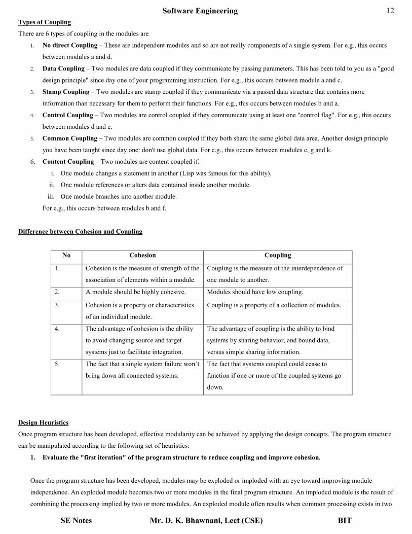
Types of Coupling
There are 6 types of coupling in the modules are
1. No direct Coupling – These are independent modules and so are not really components of a single system. For e.g., this occurs
between modules a and d.
2. Data Coupling – Two modules are data coupled if they communicate by passing parameters. This has been told to you as a "good
design principle" since day one of your programming instruction. For e.g., this occurs between module a and c.
3. Stamp Coupling – Two modules are stamp coupled if they communicate via a passed data structure that contains more
information than necessary for them to perform their functions. For e.g., this occurs between modules b and a.
4. Control Coupling – Two modules are control coupled if they communicate using at least one "control flag". For e.g., this occurs
between modules d and e.
5. Common Coupling – Two modules are common coupled if they both share the same global data area. Another design principle
you have been taught since day one: don't use global data. For e.g., this occurs between modules c, g and k.
6. Content Coupling – Two modules are content coupled if:
i. One module changes a statement in another (Lisp was famous for this ability).
ii. One module references or alters data contained inside another module.
iii. One module branches into another module.
For e.g., this occurs between modules b and f.
Difference between Cohesion and Coupling
No Cohesion Coupling
1. Cohesion is the measure of strength of the
association of elements within a module.
Coupling is the measure of the interdependence of
one module to another.
2. A module should be highly cohesive. Modules should have low coupling.
3. Cohesion is a property or characteristics
of an individual module.
Coupling is a property of a collection of modules.
4. The advantage of cohesion is the ability
to avoid changing source and target
systems just to facilitate integration.
The advantage of coupling is the ability to bind
systems by sharing behavior, and bound data,
versus simple sharing information.
5. The fact that a single system failure won’t
bring down all connected systems.
The fact that systems coupled could cease to
function if one or more of the coupled systems go
down.
Design Heuristics
Once program structure has been developed, effective modularity can be achieved by applying the design concepts. The program structure
can be manipulated according to the following set of heuristics:
1. Evaluate the "first iteration" of the program structure to reduce coupling and improve cohesion.
Once the program structure has been developed, modules may be exploded or imploded with an eye toward improving module
independence. An exploded module becomes two or more modules in the final program structure. An imploded module is the result of
combining the processing implied by two or more modules. An exploded module often results when common processing exists in two

Software Engineering
SE Notes Mr. D. K. Bhawnani, Lect (CSE) BIT
13
or more modules and can be redefined as a separate cohesive module. When high coupling is expected, modules can sometimes be
imploded to reduce passage of control, reference to global data, and interface complexity.
2. Attempt to minimize structures with high fan-out; strive for fan-in as depth increases.
The structure shown inside the cloud in Figure below does not make effective use of factoring. All modules are “pancaked” below a
single control module. In general, a more reasonable distribution of control is shown in the upper structure. The structure takes an oval
shape, indicating a number of layers of control and highly utilitarian modules at lower levels.
3. Keep the scope of effect of a module within the scope of control of that module.
The scope of effect of module e is defined as all other modules that are affected by a decision made in module e. The scope of control
of module e is all modules that are subordinate and ultimately subordinate to module e. Referring to Figure above, if module e makes
a decision that affects module r, we have a violation of this heuristic, because module r lies outside the scope of control of module e.
Software Engineering
SE Notes Mr. D. K. Bhawnani, Lect (CSE) BIT
14
4. Evaluate module interfaces to reduce complexity and redundancy and improve consistency.
Module interface complexity is a prime cause of software errors. Interfaces should be designed to pass information simply and should
be consistent with the function of a module. Interface inconsistency (i.e., seemingly unrelated data passed via an argument list or other
technique) is an indication of low cohesion. The module in question should be reevaluated.
5. Define modules whose function is predictable, but avoid modules that are overly restrictive.
A module is predictable when it can be treated as a black box; that is, the same external data will be produced regardless of internal
processing details. Modules that have internal "memory" can be unpredictable unless care is taken in their use. A module that restricts
processing to a single sub-function exhibits high cohesion and is viewed with favor by a designer. However, a module that arbitrarily
restricts the size of a local data structure, options within control flow, or modes of external interface will invariably require
maintenance to remove such restrictions.
6. Strive for “controlled entry” modules by avoiding "pathological connections."
This design heuristic warns against content coupling. Software is easier to understand and therefore easier to maintain when module
interfaces are constrained and controlled. Pathological connection refers to branches or references into the middle of a module.
Architectural Design
The software architecture of a program or computing system is the structure or structures of the system, which comprise software
components, the externally visible properties of those components and the relationships among them.
So, architecture is not the operational software. Rather, it is a representation that enables a software engineer to:
1. Analyze the effectiveness of the design in meeting its stated requirements.
2. Consider architectural alternatives at a stage when making design changes is still relatively easy, and
3. Reducing the risks associated with the construction of the software.
Why is architecture important? 3 reasons are:
1. Representations of software architecture are an enabler for communication between all parties interested in the development of a
computer – based system.
2. Architecture highlights early design decisions that will have a profound impact on all software engineering work that follows.
3. Architecture constitutes a relatively small, intellectually graspable model of how the system is structured and how its components
work together.
Principles of Data design – by Wasserman
Wasserman proposed the following principles:
1. The systematic analysis principles applied to function and behavior should also be applied to data.
2. All data structures and operations to be performed on each should be identified.
3. A data dictionary should be established and used to define both data and program design.
4. Low – level data design decisions should be deferred until late in design process.
5. The representation of data structure should be known only to those modules that must make direct use of the data contained
within the structure.
6. A library of useful data structures and the operations that may be applied to them should be developed.
7. A software design and programming language should support the specification and realization of abstract data types.

Software Engineering
SE Notes Mr. D. K. Bhawnani, Lect (CSE) BIT
15
Design Notations
In software design the representation schemes are of fundamental importance. A good design can clarify the interrelationships and actions
of interest, while poor notation can compliance and interfere with good practice. At least three levels of design specifications exist: external
design specifications, which describe the external characteristics of a software system; architectural design specifications, which describe
the structure of the system; and detailed design specifications, which describe control flow, data representation, and other algorithmic
details within the modules. Some common design notations are as follows:
Data flow diagrams (Bubble chart)
1) These are directed graphs in which the nodes specify processing activities and arcs (lines with arrow heads) specify the data items
transmitted between the processing nodes.
2) Like flowcharts, data flow diagrams can be used at any desired level of abstraction.
3) Unlike flowcharts, data flow diagrams do not indicate decision logic or conditions under which various processing nodes in the diagram
might be activated.
4) They might represent data flow :-
a) Between individual statements or blocks of statements in a routine,
b) Between sequential routines,
c) Between concurrent processes,
d) Between geographically remote processing units.
5) The DFDs have basic two levels of development, they are as follows –
1) A Level 0 DFD, also known as Fundamental System Model or Context Model, represents the entire system as a single bubble
with incoming arrowed lines as the input data and outgoing arrowed lines as output.
2) A Level 1 DFD might contain 5 or 6 bubbles with interconnecting arrows. Each process represented here is the detailed view
of the functions shown in the level 0 DFD.
• Here the rectangular boxes are used to represent the external entities that may act as input or output outside the system.
• Round Circles are used to represent any kind of transformation process inside the system.
• Arrow headed lines are used to represent the data object and its direction of flow.
6) Following are some guidelines for developing a DFD:-
1) Level 0 DFD should depict the entire software system as a single bubble.
2) Primary input and output should be carefully noted.
3) For the next level of DFD the candidate processes, data objects and stores should be recognized distinctively.
4) All the arrows and bubbles should be labeled with meaningful names.
5) Information flow continuity should be maintained in all the levels.
6) One bubble should be refined at a time.
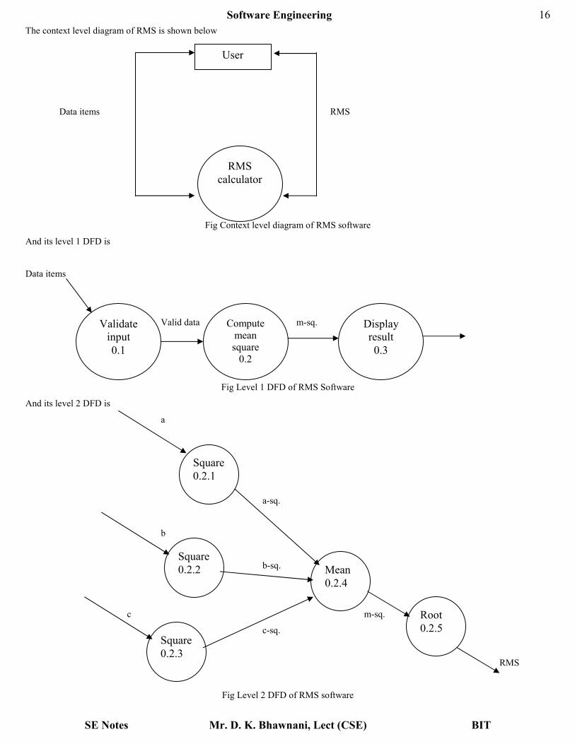
Example: Let us consider a software system called the root mean square (RMS) calculating system which reads 3 integers in the range
from – 1000 to + 1000 and calculate their RMS value and then display it.
Software Engineering
SE Notes Mr. D. K. Bhawnani, Lect (CSE) BIT
16
The context level diagram of RMS is shown below
Data items RMS
Fig Context level diagram of RMS software
And its level 1 DFD is
Data items
Valid data m-sq.
Fig Level 1 DFD of RMS Software
And its level 2 DFD is
a
a-sq.
b
b-sq.
c m-sq.
c-sq.
RMS
Fig Level 2 DFD of RMS software
User
RMS
calculator
Validate
input
0.1
Compute
mean
square
0.2
Display
result
0.3
Square
0.2.1
Square
0.2.2
Square
0.2.3
Mean
0.2.4
Root
0.2.5
Software Engineering
SE Notes Mr. D. K. Bhawnani, Lect (CSE) BIT
17
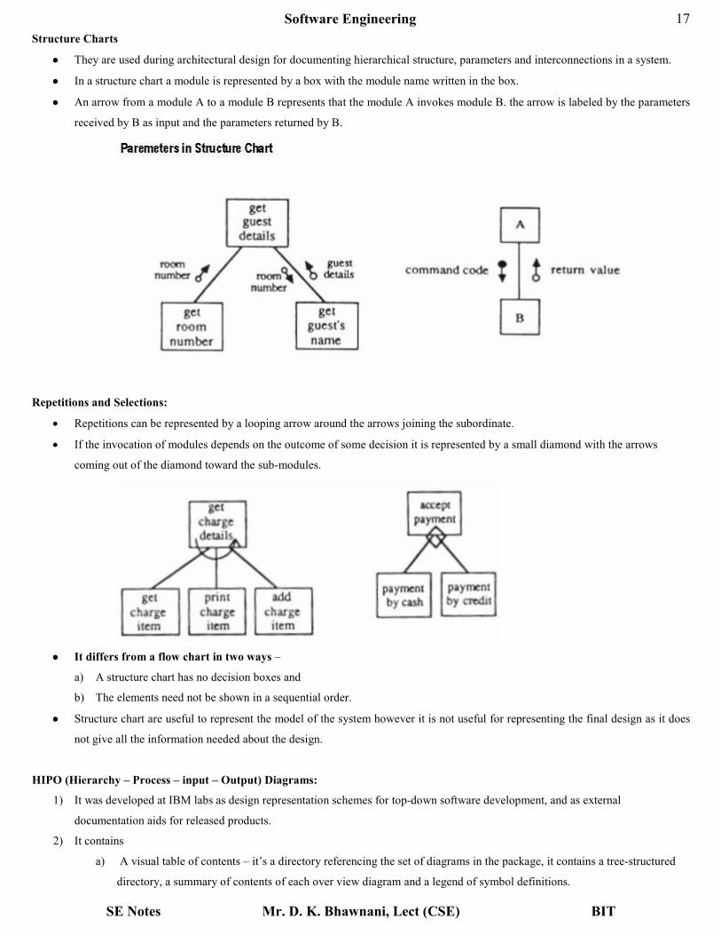
Structure Charts
•••• They are used during architectural design for documenting hierarchical structure, parameters and interconnections in a system.
•••• In a structure chart a module is represented by a box with the module name written in the box.
•••• An arrow from a module A to a module B represents that the module A invokes module B. the arrow is labeled by the parameters
received by B as input and the parameters returned by B.
Repetitions and Selections:
• Repetitions can be represented by a looping arrow around the arrows joining the subordinate.
• If the invocation of modules depends on the outcome of some decision it is represented by a small diamond with the arrows
coming out of the diamond toward the sub-modules.
•••• It differs from a flow chart in two ways –
a) A structure chart has no decision boxes and
b) The elements need not be shown in a sequential order.
•••• Structure chart are useful to represent the model of the system however it is not useful for representing the final design as it does
not give all the information needed about the design.
HIPO (Hierarchy – Process – input – Output) Diagrams:
1) It was developed at IBM labs as design representation schemes for top-down software development, and as external
documentation aids for released products.
2) It contains
a) A visual table of contents – it’s a directory referencing the set of diagrams in the package, it contains a tree-structured
directory, a summary of contents of each over view diagram and a legend of symbol definitions.

Software Engineering
SE Notes Mr. D. K. Bhawnani, Lect (CSE) BIT
18
b) A set of overview diagrams – they specify the functional processes in a system. Each overview diagram describes the
inputs, processing steps and output for the explained function.
c) A set of detail diagrams – which has the same format as over view diagrams.
Structured English
Structured English can be used to provide a step-by step specification for an algorithm.
It can be used at any desirable level of detail.
•••• A rigid subset of the English language omitting adjectives, adverbs, compound and complex sentences, all verb modes except
imperative and most punctuation
•••• Result: A language containing a limited set of conditional and logic statements with nouns and strong verbs
Standards vary between organizations - objectives of: conciseness, preciseness and lack of ambiguity apply to all variants.
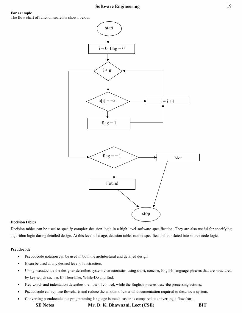
Structured Flowcharts:
• Flowcharts are the traditional means of specifying and documenting algorithmic details in a software system
• They are graphical representation to show the flow of information and control from element to element in a system.
• The information flow represented here is sequential.
• It is a pictorial representation of an algorithm that uses symbols to show the operations and decisions to be followed.
• They incorporate - Rectangular boxes representing some action, Diamond shaped boxes for decisions, directed arcs (arrow headed
lines) for specifying interconnection and information flow between the boxes and various other graphical shapes for the
representation of data stores, input, output etc.
Software Engineering
SE Notes Mr. D. K. Bhawnani, Lect (CSE) BIT
19
For example The flow chart of function search is shown below:
Decision tables
Decision tables can be used to specify complex decision logic in a high level software specification. They are also useful for specifying
algorithm logic during detailed design. At this level of usage, decision tables can be specified and translated into source code logic.
Pseudocode
• Pseudocode notation can be used in both the architectural and detailed design.
• It can be used at any desired level of abstraction.
• Using pseudocode the designer describes system characteristics using short, concise, English language phrases that are structured
by key words such as If- Then-Else, While-Do and End.
• Key words and indentation describes the flow of control, while the English phrases describe processing actions.
• Pseudocode can replace flowcharts and reduce the amount of external documentation required to describe a system.
• Converting pseudocode to a programming language is much easier as compared to converting a flowchart.
start
i = 0, flag = 0
i < n
a[i] = =x
flag = 1
i = i +1
flag = = 1
Found
Not
stop
Software Engineering
SE Notes Mr. D. K. Bhawnani, Lect (CSE) BIT
20
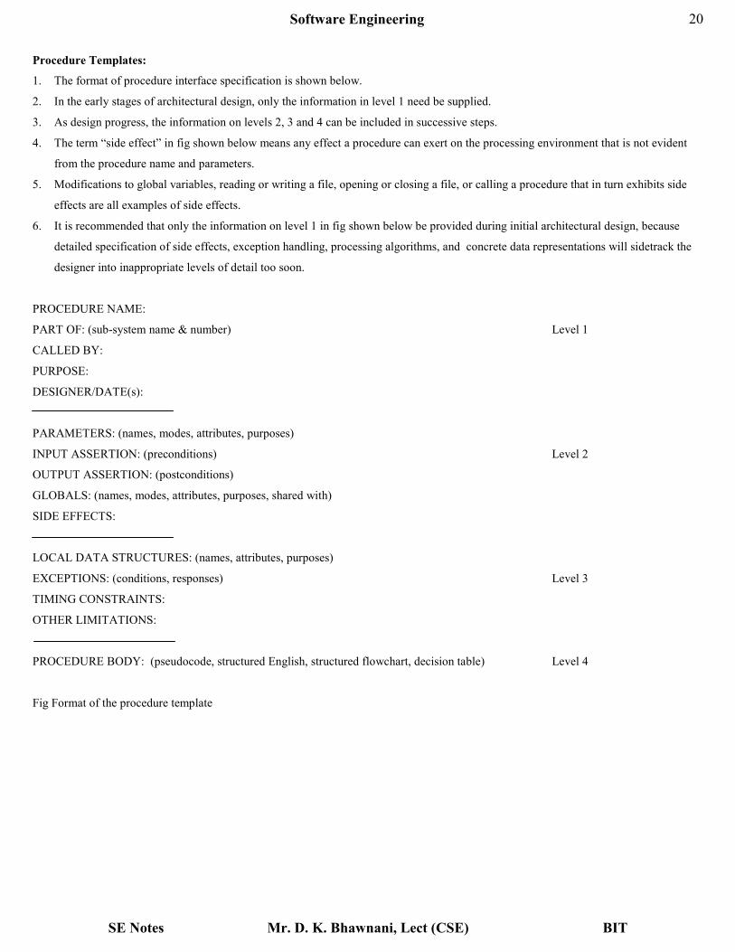
Procedure Templates:
1. The format of procedure interface specification is shown below.
2. In the early stages of architectural design, only the information in level 1 need be supplied.
3. As design progress, the information on levels 2, 3 and 4 can be included in successive steps.
4. The term “side effect” in fig shown below means any effect a procedure can exert on the processing environment that is not evident
from the procedure name and parameters.
5. Modifications to global variables, reading or writing a file, opening or closing a file, or calling a procedure that in turn exhibits side
effects are all examples of side effects.
6. It is recommended that only the information on level 1 in fig shown below be provided during initial architectural design, because
detailed specification of side effects, exception handling, processing algorithms, and concrete data representations will sidetrack the
designer into inappropriate levels of detail too soon.
PROCEDURE NAME:
PART OF: (sub-system name & number) Level 1
CALLED BY:
PURPOSE:
DESIGNER/DATE(s):
PARAMETERS: (names, modes, attributes, purposes)
INPUT ASSERTION: (preconditions) Level 2
OUTPUT ASSERTION: (postconditions)
GLOBALS: (names, modes, attributes, purposes, shared with)
SIDE EFFECTS:
LOCAL DATA STRUCTURES: (names, attributes, purposes)
EXCEPTIONS: (conditions, responses) Level 3
TIMING CONSTRAINTS:
OTHER LIMITATIONS:
PROCEDURE BODY: (pseudocode, structured English, structured flowchart, decision table) Level 4
Fig Format of the procedure template

Software Engineering
SE Notes Mr. D. K. Bhawnani, Lect (CSE) BIT
21
Mapping Requirements into Software Architecture
There are two types of information flow which are the drivers for the mapping approach:
a) Transform Flow.
b) Transaction Flow.
Transform Flow – Information must enter and exit software in an “external world” form. External data (like data typed on keyboard,
tones on a telephone line and video images in multimedia application) must be converted into an internal form for processing. Information
enters the system along paths that transform external data into an internal form. These paths are identified as incoming flow. At the kernel
of the software, a transition occurs. Incoming data are passed through a ‘transform center’ and begin to move along paths that now lead
“out” of the software. Data moving along these paths are called outgoing flow. The overall flow of data occurs in a sequential manner and
follows straight line paths. When a segment of a DFD exhibits these characteristics, ‘transform flow’ is present.
Transaction Flow – The fundamental system model implies transaction flow; therefore, it is possible to characterize all data flow by a
single data item, called a transaction that triggers other data flow along one of the many paths. So, when DFD takes the form as shown
below, transaction flow is present.
Fig Transaction Flow
Transaction flow is characterized by data moving along an incoming path that converts external world information into a transaction. The
transaction is evaluated and based on its value; flow along one of many action paths is initiated. “The hub of information flow from
which many actions path originate is called a transaction center”.
It should be note that, within a DFD for a large system, both transform flow and transaction flow may be present. For example, in a
transaction – oriented flow, information flow along an action path may have transform flow characteristics.

Software Engineering
SE Notes Mr. D. K. Bhawnani, Lect (CSE) BIT
22
Transform Mapping – “Transform Mapping is a set of design steps that allow a DFD with transform flow characteristics to be mapped
into a specific architectural style”.
Structural design provides 2 strategies to guide transformation of a DFD into a structure chart:
a) Transform Analysis
b) Transaction Analysis
Transform Analysis (Transaction mapping) – It identifies the primary functional components (modules) and the high level input and
output for these components.
First step in transform analysis is to divide the DFD into three parts:
a) Input
b) Logical processing
c) Output
The input portion in the DFD includes processes that transform input data from physical (e.g., character from terminal) to logical form
(e.g., internal tables, lists etc). Each input portion is called ‘afferent branch’. There may be more than one afferent branch in a DFD.
The output portion of a DFD transforms output data from logical to physical form. Each output portion is called on ‘efferent branch’. The
remaining portion of a DFD is called central transform.
In second step of transform analysis, the structure chart is derived by drawing one functional component for each central transform, for
each afferent and efferent branch. Identifying the highest level input and output transforms requires experience and skill. One possible
approach is to trace the inputs until a bubble is found whose output cannot be deduced from its inputs alone. Processes which validate
input or add information to them are not central transforms. Processes which sort input of filter data from it are central transforms. The first
level of structure chart is produced by representing each input and output unit as boxes and each transform as a single box.
In the third step of transform analysis, the structure chart is refined by adding sub– functions required by each of the high level
functional components. Many levels of functional components may be added. This process of breaking functional components into
subcomponents is called ‘factoring’. Factoring includes adding, read and write modules, error handling modules, initialization and
termination processes. The factoring process is continued until all bubbles in the DFD are represented in the structure chart.
Example: Let us consider a software system called the root mean square (RMS) calculating system which reads 3 integers in the range
from – 1000 to + 1000 and calculate their RMS value and then display it. Apply transform analysis to design its structure chart.
Sol:
Software Engineering
SE Notes Mr. D. K. Bhawnani, Lect (CSE) BIT
23
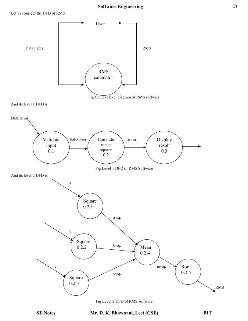
Let us consider the DFD of RMS
Data items RMS
Fig Context level diagram of RMS software
And its level 1 DFD is
Data items
Valid data m-sq.
Fig Level 1 DFD of RMS Software
And its level 2 DFD is
a
a-sq.
b
b-sq.
c m-sq.
c-sq.
RMS
Fig Level 2 DFD of RMS software
User
RMS
calculator
Validate
input
0.1
Compute
mean
square
0.2
Display
result
0.3
Square
0.2.1
Square
0.2.2
Square
0.2.3
Mean
0.2.4
Root
0.2.5

Software Engineering
SE Notes Mr. D. K. Bhawnani, Lect (CSE) BIT
24
By observing, level 1 DFD, we can identify the read input and validate input as the afferent branch and the write output as the efferent
branch. By applying the 2nd and 3
rd steps of transform analysis, we get the structure chart below
Valid data RMS
Data items Data items valid data
Fig Structure chart of RMS software
Transaction analysis (Transaction mapping) – It is an alternative to transform analysis and is useful while designing transaction
processing programs. A transform centered system is characterized by similar processing steps for each data item processed by input,
process and output systems. In a transaction driven system, one of several possible paths through the DFD is traversed depending upon the
input data item.
A transaction is any element of data that triggers an action. Every transaction carries a tag identifying its type. Transaction
analysis uses this tag to divide the system into transaction modules and a transaction center module. This is an architectural design.
User Interface Design
Interface design focuses on three areas of concern:
a) The design of interfaces between software components,
b) The design of interfaces between the software and other nonhuman producers and consumers of information (i.e., other external
entities), and
c) The design of the interface between a human (i.e., the user) and the computer.
User Interface Design Principles
Theo Mandel coins three “golden rules” for user interface design:
1. Place the user in control.
2. Reduce the user’s memory load.
3. Make the interface consistent.
1. Place the user in control
During a requirements gathering session for a major new information system, a key user was asked about the attributes of the window
oriented graphical interface. Mandel defines a number of design principles that allow the user to maintain control:
a) Define interaction modes in a way that does not force a user into unnecessary or undesired actions.
b) Provide for flexible interaction.
c) Allow user interaction to be interruptible and undoable.
d) Streamline interaction as skill levels advance and allow the interaction to be customized.
e) Hide technical internals from the casual user.
f) Design for direct interaction with objects that appear on the screen.
Main
Compute–RMS Write–result Get–good–data
Read–input Validate–input

Software Engineering
SE Notes Mr. D. K. Bhawnani, Lect (CSE) BIT
25
2. Reduce the user’s memory load
The more a user has to remember, the more error-prone will be the interaction with the system. It is for this reason that a well-designed
user interface does not tax the user’s memory. Whenever possible, the system should “remember” pertinent information and assist the user
with an interaction scenario that assists recall. Mandel defines design principles that enable an interface to reduce the user’s memory load:
a) Reduce demand on short – term memory.
b) Establish meaningful defaults.
c) Define shortcuts that are intuitive.
d) The visual layout of the interface should be based on a real world metaphor.
e) Disclose information in a progressive fashion.
3. Make the interface consistent
The interface should present and acquire information in a consistent fashion. This implies that
(1) All visual information is organized according to a design standard that is maintained throughout all screen displays,
(2) Input mechanisms are constrained to a limited set that are used consistently throughout the application, and
(3) Mechanisms for navigating from task to task are consistently defined and implemented.
Mandel defines a set of design principles that help make the interface consistent:
a) Allow the user to put the current task into a meaningful context.
b) Maintain consistency across a family of applications.
c) If past interactive models have created user expectations, do not make changes unless there is a compelling reason to do so.
The User Interface Design Process
The design process for user interfaces is iterative and can be represented using a spiral model. Referring to Figure below, the user interface
design process encompasses four distinct framework activities:
a) User, task, and environment analysis and modeling
b) Interface design
c) Interface construction
d) Interface validation
The spiral shown in Figure below implies that each of these tasks will occur more than once, with each pass around the spiral representing
additional elaboration of requirements and the resultant design. In most cases, the implementation activity involves prototyping—the only
practical way to validate what has been designed.
Fig User Interface Design Process

Software Engineering
SE Notes Mr. D. K. Bhawnani, Lect (CSE) BIT
26
a) User, task, and environment analysis and modeling
The initial analysis activity focuses on the profile of the users who will interact with the system. Skill level, business understanding, and
general receptiveness to the new system are recorded; and different user categories are defined. For each user category, requirements are
elicited. In essence, the software engineer attempts to understand the system perception for each class of users.
Once general requirements have been defined, a more detailed task analysis is conducted. Those tasks that the user performs to accomplish
the goals of the system are identified, described, and elaborated (over a number of iterative passes through the spiral).
The analysis of the user environment focuses on the physical work environment. Among the questions to be asked are
• Where will the interface be located physically?
• Will the user be sitting, standing, or performing other tasks unrelated to the interface?
• Does the interface hardware accommodate space, light, or noise constraints?
• Are there special human factors considerations driven by environmental factors?
b) Interface design
The information gathered as part of the analysis activity is used to create an analysis model for the interface. Using this model as a basis,
the design activity commences. The goal of interface design is to define a set of interface objects and actions (and their screen
representations) that enable a user to perform all defined tasks in a manner that meets every usability goal defined for the system.
c) Interface construction
The implementation activity normally begins with the creation of a prototype that enables usage scenarios to be evaluated. As the iterative
design process continues, a user interface tool kit may be used to complete the construction of the interface.
d) Interface validation
Validation focuses on
1. The ability of the interface to implement every user task correctly, to accommodate all task variations, and to achieve all general
user requirements;
2. The degree to which the interface is easy to use and easy to learn; and
3. The users’ acceptance of the interface as a useful tool in their work.
Milestones, Walkthroughs and Inspections
These activities help in exposing errors, provide increased project communication, keeping the project in schedule, and verification that the
design satisfies the requirements.
Milestones
1) These are a set of occasions in project design where the proper progress of the project can be assessed in such a way that corrective
measures could be taken if necessary.
a) The two major milestones are –
i. Preliminary Design Review (PDR) :- Its normally held near the end of architectural design and prior to detailed design
ii. Critical design Review (CDR) :- Its normally held at the end of detailed design and prior to implementation.
b) The major goal of PDR is to demonstrate the externally observable characteristics and architectural structure of the product which
would satisfy the customer’s requirements. Functional characteristics, performance attributes, external interface, user dialogs,
report formats, exception conditions and exception handling and future enhancements are reviewed during PDR.
c) The CDR provides a final management decision point , to build or cancel the system.
Phases :- Analysis Design Implementatio

Software Engineering
SE Notes Mr. D. K. Bhawnani, Lect (CSE) BIT
27
n
Activities :-
Planning
&
Requirement
definition
External,
Architectural
and Detailed
Coding,
Debugging
and Testing
Reviews :- SRR PDR CDR
SRR :- Software Requirements Review
PDR :- Preliminary Design Review.
CDR :- Critical Design Review.
Walkthroughs
1) A structured walkthrough is an in-depth, technical review of some aspects of a software system. Walkthroughs can be anytime , during
any phase of a software project.
2) A walkthrough team consists of 4 to 6 people. The person whose material is being reviewed is responsible for providing copies of the
review materials to the members of the walkthrough group in advance of the walkthrough session and the team members are
responsible for understanding the reviewing material before the session.
3) During the walkthrough the reviewed “walks through” the material while the reviewers look for errors, request clarification and
explore problem areas in the material under review.
4) High-level managers should not attend walkthrough sessions as the aim of walkthroughs is error detection not corrective action. Its
important to note that the material is reviewed not the person whose material is being reviewed.
Inspections
1) Design inspections are conducted by teams of trained inspectors who have a check list of items to be examined.
2) Special forms are used to record problems encountered.
3) A typical inspection team consists of a Moderator or Secretary, a Designer, an Implementor and a Tester. The Designer, Implementor
and Tester may or may not be the people responsible for the actual design, implementation and testing of the product being inspected.
4) The team members are trained for their specific roles and typically conduct a dual 2-hrs sessions per day.

Software Engineering
SE Notes Mr. D. K. Bhawnani, Lect (CSE) BIT
28
Software Configuration Management
1. Software configuration management (SCM) is an umbrella activity that is applied throughout the software process, because
change can occur at any time.
2. SCM activities are developed to
(1) Identify change,
(2) Control change,
(3) Ensure that change is being properly implemented, and
(4) Report changes to others who may have an interest.
3. It is important to make a clear distinction between software support and software configuration management. Support is a set of
software engineering activities that occur after software has been delivered to the customer and put into operation. Software
configuration management is a set of tracking and control activities that begin when a software engineering project begins and
terminate only when the software is taken out of operation.
4. A primary goal of software engineering is to improve the ease with which changes can be accommodated and reduce the amount
of effort expended when changes must be made.
5. The output of the software process is information that may be divided into three broad categories:
(1) Computer programs (both source level and executable forms);
(2) Documents that describe the computer programs (targeted at both technical practitioners and users), and
(3) Data (contained within the program or external to it).
The items that comprise all information produced as part of the software process are collectively called a software
configuration.
6. As the software process progresses, the number of software configuration items (SCIs) grows rapidly. A System Specification
spawns a Software Project Plan and Software Requirements Specification (as well as hardware related documents). These in
turn spawn other documents to create a hierarchy of information. If each SCI simply spawned other SCIs, little confusion would
result. Unfortunately, another variable enters the process—change. Change may occur at any time, for any reason. In fact, the
First Law of System Engineering states: “No matter where you are in the system life cycle, the system will change, and the desire
to change it will persist throughout the life cycle.”
7. There are four fundamental sources of change:
a) New business or market conditions dictate changes in product requirements or business rules.
b) New customer needs demand modification of data produced by information systems, functionality delivered by products,
or services delivered by a computer-based system.
c) Reorganization or business growth/downsizing causes changes in project priorities or software engineering team
structure.
d) Budgetary or scheduling constraints cause a redefinition of the system or product.
8. Software configuration management is a set of activities that have been developed to manage change throughout the life cycle of
computer software. SCM can be viewed as a software quality assurance activity that is applied throughout the software process.
Baselines
A baseline is a software configuration management concept that helps us to control change without seriously impeding justifiable change.
The IEEE defines a baseline as: “A specification or product that has been formally reviewed and agreed upon, that thereafter serves as the
basis for further development, and that can be changed only through formal change control procedures.
Software Engineering
SE Notes Mr. D. K. Bhawnani, Lect (CSE) BIT
29
One way to describe a baseline is through analogy:
Consider the doors to the kitchen in a large restaurant. One door is marked OUT and the other is marked IN. The doors have stops that
allow them to be opened only in the appropriate direction.
If a waiter picks up an order in the kitchen, places it on a tray and then realizes he has selected the wrong dish, he may change to
the correct dish quickly and informally before he leaves the kitchen.
If, however, he leaves the kitchen, gives the customer the dish and then is informed of his error, he must follow a set procedure:
(1) Look at the check to determine if an error has occurred,
(2) Apologize profusely,
(3) Return to the kitchen through the IN door,
(4) Explain the problem, and so forth.
A baseline is analogous to the kitchen doors in the restaurant. Before a software configuration item becomes a baseline, change may be
made quickly and informally. However, once a baseline is established, we figuratively pass through a swinging oneway door. Changes can
be made, but a specific, formal procedure must be applied to evaluate and verify each change.
In the context of software engineering, a baseline is a milestone in the development of software that is marked by the delivery of one or
more software configuration items and the approval of these SCIs that is obtained through a formal technical review. For example, the
elements of a Design Specification have been documented and reviewed. Errors are found and corrected. Once all parts of the
specification have been reviewed, corrected and then approved, the Design Specification becomes a baseline. Further changes to the
program architecture (documented in the Design Specification) can be made only after each has been evaluated and approved. Although
baselines can be defined at any level of detail, the most common software baselines are shown in Figure below.
The progression of events that lead to a baseline is also illustrated in Figure below. Software engineering tasks produce one or more SCIs.
After SCIs are reviewed and approved, they are placed in a project database (also called a project library or software repository). When a
member of a software engineering team wants to make a modification to a baselined SCI, it is copied from the project database into the
engineer's private work space. However, this extracted SCI can be modified only if SCM controls are followed. The arrows in Figure
above illustrate the modification path for a baselined SCI.

Software Engineering
SE Notes Mr. D. K. Bhawnani, Lect (CSE) BIT
30
Fig Baselined SCIs and the project database
Software Configuration Items
1. A SCI could be considered to be a single section of a large specification or one test case in a large suite of tests.
2. An SCI is a document, an entire suite of test cases, or a named program component (e.g., a C++ function or an Ada package).
3. In addition to the SCIs that are derived from software work products, many software engineering organizations also place
software tools under configuration control. That is, specific versions of editors, compilers, and other CASE tools are "frozen" as
part of the software configuration. Because these tools were used to produce documentation, source code, and data, they must be
available when changes to the software configuration are to be made.
4. Although problems are rare, it is possible that a new version of a tool (e.g., a compiler) might produce different results than the
original version. For this reason, tools, like the software that they help to produce, can be baselined as part of a comprehensive
configuration management process. In reality, SCIs are organized to form configuration objects that may be cataloged in the
project database with a single name.
5. A configuration object has a name, attributes, and is "connected" to other objects by relationships. Referring to Figure below, the
configuration objects, Design Specification, data model, component N, source code and Test Specification are each defined
separately. However, each of the objects is related to the others as shown by the arrows. A curved arrow indicates a

Software Engineering
SE Notes Mr. D. K. Bhawnani, Lect (CSE) BIT
31
compositional relation. That is, data model and component N are part of the object Design Specification. A double-headed
straight arrow indicates an interrelationship.
6. If a change were made to the source code object, the interrelationships enable a software engineer to determine what other objects
(and SCIs) might be affected.
Fig Configuration objects
SCM Process
The five basic SCM tasks are
i) Identification of objects,
ii) Version control,
iii) Change control,
iv) Configuration auditing and
v) Reporting.
1) Identification of objects – To control and manage SCIs, each of them must be separately named and then organized using object-
oriented approach. The SCIs can be classified in to two kinds of objects –
a) Basic objects and
b) Aggregate objects.
Software Engineering
SE Notes Mr. D. K. Bhawnani, Lect (CSE) BIT
32
a) Basic object – It’s a “unit of text” created by a software engineer during analysis, design, coding or testing phases.
For example, a basic object might be a section of a requirements specification, a source listing for a component, or a
suite of test cases that are used to exercise the code.
b) Aggregate object – It’s a collection of basic objects and other aggregate objects.
For example, Design Specification is an aggregate object.
Each object has a set of unique features for distinct identification. Every object should have –
i. An unique name,
ii. A description of the object including its SCI type eg. Document, program or data, a project identifier and version
information,
iii. A list of resources, which are entities that are processed, provided or required by the object.
2) Version control – It combines various tools and procedures to manage and control different versions of SCI objects (as a result of
change) that are created during the software engineering process. Clemm describes version control in the context of SCM:
“Configuration management allows a user to specify alternative configurations of the software system through the selection of
appropriate versions. This is supported by associating attributes with each software version, and then allowing a configuration to
be specified [and constructed] by describing the set of desired attributes”.
These "attributes" mentioned can be as simple as a specific version number that is attached to each object or as complex as a
string of Boolean variables (switches) that indicate specific types of functional changes that have been applied to the system.
3) Change control – For a large system development project, uncontrolled change rapidly leads to confusion and inconsistencies.
Change control includes human procedures and automated tools to control the reasons for change. The following processes take
place when a situation of change occurs:
i. Change request – A change request is first submitted and then it is evaluated to asses its –
i) Technical merit,
ii) Potential side effects, subsystems and the cost for implementing the change.
ii. Change report – After the evaluation is done, a change report is created that is submitted to the Change Control
Authority/Board (CCA or CCB). CCA or CCB is a group who are responsible for evaluating the change report and
makes the final decision on the status and priority of the change. This group generates an Engineering Change Order
(ECO) for each approved change.
iii. ECO (Engineering Change Order) – It consists of
i) The description of the change to be made,
ii) Constraints that has to be taken care of and
iii) Criteria for review and audit.
iv. Check out & check in – The object to be changed is “checked out” of the project database, the decided changes are
made and appropriate SQA (Software Quality Assurance) activities are performed. The object is then “checked in” the
project database and appropriate version control mechanisms are used to create the next version of the software.
4) Formal technical reviews (FTR) & Configuration audit – These two activities are required to ensure that the change made to
the software is properly implemented.

Software Engineering
SE Notes Mr. D. K. Bhawnani, Lect (CSE) BIT
33
a) Formal technical reviews (FTR) – It’s a part of Software Quality Assurance (SQA) procedures. The objectives of FTR are
i) To uncover errors in functions, logic or implementation,
ii) To verify that the software under review should meet its requirement,
iii) To ensure that the representation of the software is according to the standards,
iv) To make the project more manageable
v) It consists of walkthroughs, inspections and round-robin reviews.
b) Software configuration audit – It consists of the following auditing procedures
i) To check whether the changes specified in the ECO (Engineering Change Order) has been properly made and to check
if any additional modules are added,
ii) To check whether formal technical reviews are conducted for the assessment of technical correctness,
iii) To check whether SE standards are properly followed,
iv) To check whether the change is highlighted in the SCI (Software Configuration Items) documentation and also the
attributes of the configuration object should reflect the change,
v) To check whether SCM (Software Configuration Management) procedures like noting change, recording it and
reporting it has been properly done,
vi) To check whether all the related SCIs are properly updated.
5) Configuration Status reporting (CSR) – Its an SCM task which summarizes the activities done so far which includes the
following
a) The report of all the activities done,
b) The report on the persons involved in the above reported activities,
c) The report on the time and date when the reported activities were accomplished,
d) The report on various other factors or objects that will be affected due to the reported activity.
Following are the situations where the CSR needs updating
a) Each time when a SCI is assigned a new or updated identification,
b) Each time ECO is issued i.e a when a change is approved by the CCA/CCB,
c) Each time a configuration audit is conducted.
The CSR is made available online and is updated occasionally in order to keep the management and concerned individuals
updated on the changes. It improves the communication among all the people involved.