solar heat gain through fenestration systems containing shading
TRANSCRIPT

SOLAR HEAT GAIN THROUGH FENESTRATION SYSTEMSCONTAINING SHADING: SUMMARY OF PROCEDURES FOR
ESTIMATING PERFORMANCE FROM MINIMAL DATA
J. H. Klems
Building Technologies Department
Lawrence Berkeley National Laboratory
Berkeley, CA 94720
Abstract
The computational methods for calculating the properties of glazing systemscontaining shading from the properties of their components have beendeveloped, but the measurement standards and property data bases necessaryto apply them have not. It is shown that with a drastic simplifyingassumption these methods can be used to calculate system solar-opticalproperties and solar heat gain coefficients for arbitrary glazing systems,while requiring limited data about the shading. Detailed formulas arepresented, and performance multipliers are defined for the approximatetreatment of simple glazings with shading. As higher accuracy is demanded,the formulas become very complicated.
INTRODUCTION
Several years ago ASHRAE sponsored a research project, 548-RP, to develop a method ofdetermining the solar heat gain coefficient for complex fenestration systems, i.e., thosecontaining non-specular (and presumably geometrically complex) sun-control or visibilityelements, such as shades, venetian blinds, or translucent glazings. These systems had beencharacterized using the shading coefficient, a concept developed when only clear singleglazing was common. The basic idea behind the shading coefficient was that for mostsystems the chief dependence of the solar transmission on wavelength and incident anglecame from the glass layer, and the reflectance and absorptance of this layer were not large.It was therefore possible to treat shading systems as providing a modifying factor to thesingle glass transmittance, and this factor being assumed independent of incident angle, itcould be determined by a single measurement in a calorimeter.
As multiple glazings and coated glasses were introduced, the basic assumption of theshading coefficient ceased to be valid, and it was gradually replaced with the solar heat gain
2coefficient (SHGC), which is a quantity with an explicit dependence on incident angle. For“simple” glazing systems (those consisting only of layers of unshaded glass), the SHGCcan be calculated from a simple formula,
SHGC(θ) = T(θ) + Nk ⋅ Ak (θ)
k = 1
L
∑ , (1)
where T represents the overall solar-optical transmittance of the system (at the incident angleθ ) and Ak represents the solar-optical absorptance for each of the glazing layers (assumedto be L in number). The layer inward-flowing fractions, Nk , represent the fraction of theenergy absorbed in each layer that reaches the interior space. The system transmittance andlayer absorptances can be calculated from optical measurements made on the individualglass layers. These are generally made with a spectrophotometer. Systematic collections ofsuch properties have been compiled. (Windows and Daylighting Group, 2001) The layerinward-flowing fractions can be calculated from heat transfer theory, utilizing measuredthermal transmittance coefficients for the gas spaces between the glazings. Standardizedcomputer codes exist to derive the solar heat gain coefficient from the spectrophotometricdata. (Windows and Daylighting Group 1994; Wright 1995; Wright 1998)
Equation 1 and the associated calculation methodologies represent a very significantsimplification of the problem of characterizing glazing systems. This can be seen from thefollowing argument. If the number of glazing products from which glazing systems may becomposed is G, then the number of possible double glazed systems is G2, the number ofpossible 3-layer systems is G3, etc. If one needs to characterize each glazing system bymeasurement, there is a much larger number of characterizations to be made than if oneneeds only to characterize the individual glazing layers. This is known as the“combinatorial problem”. And the number G is not small. At present there are more than900 products listed in the WINDOW-4.1 Spectral Data Library. While the differencesbetween many of these products are small, even the type of generic characterization thatASHRAE favors could scarcely be expected to use a number for G smaller than 20. Soeven though wavelength-by-wavelength measurements are needed to calculate the T and Ain equation 1, there is still a great savings in labor from not needing to measure all possiblecombinations.
If one now considers the problem of characterizing glazing systems with shading layers,and if the number of possible shading products is S, then just the fact that double glazingsystems are common means that one must consider three-layer systems, and the number ofpossible systems becomes
€
3G2S (assuming only one shading layer, which can be in any ofthree locations). But any type of shading product is likely to come in a very large numberof colors and patterns. The author is aware of a venetian blind manufacturer that offersnearly one hundred color options for a single line of venetian blinds. Even assuming the(unrealistically) modest values of G=20, S=10 yields over 12,000 possible combinations.One sees how far we have departed from the era when the shading coefficient wasdeveloped, in which G was one, the number of possible shaded systems was 2S (interiorand exterior shading), and S itself was fairly small.
Equation 1 cannot be used for glazing systems that contain a shading element because thereflectance and transmittance of such an element is not specular: incoming radiation from aparticular direction produces transmitted or reflected radiation in many directions. This
3means that the only method of determining the solar heat gain coefficient for a glazing withshading was the procedure originally used to determine shading coefficient, measurement ofthe entire system in a calorimeter. But now measurements would need to be made for anumber of different incident directions on each system. The difficulty and expense of doingthese measurements, coupled with the combinatorial problem described above made ithighly desirable to find a method of characterizing glazings with shading elements that wasmore consonant with Equation 1. (These systems were termed “complex glazing systems”,because the shading elements add optical and geometric complexity.) This was the task of548-RP.
The research project began by defining an analog of Equation 1 applicable to complexglazing systems:
SHGC(θ, φ) = T(θ, φ) + Nk ⋅ Ak (θ, φ)
k= 1
L
∑ (2)
where now φ, the azimuthal angle of the incident direction enters the expressions for thesolar-optical quantities, since complex glazing systems are not necessarily symmetric aboutthe normal to the glazing plane (e.g., glazings with venetian blinds). Here L is now the totalnumber of layers, including shading layers. That such an expression exists follows frombasic physical principles, energy conservation and superposition; the problem lay in findinga way to determine T, Ak and Nk. The research project was able to do this, and in its severalpublications (Klems 1994A; Klems 1994B; Klems and Warner 1995; Klems, Warner et al.1995; Klems and Kelley 1996; Klems, Warner et al. 1996) it set forth these methods andalso verified the resulting expression for Equation 2 by calorimetric measurements on adouble-glazed system with a venetian blind.
Many shading layers have an inhomogeneous construction that repeats in one or twodirections; for example, drapes, woven shades, sun screens, and venetian blinds. The scaleof this inhomogeneity varies. In a woven shade the weave provides a repeating rectangularlattice with a scale of a fraction of a millimeter. A venetian blind is a repeating assembly ofslats along one direction, with a repeat dimension on the order of a few centimeters. A sunscreen sometimes consists of either (or both) horizontal or vertical slats with a dimension ofa few millimeters, while a drape has the rectangular weave of the shade with a superimposedand much larger linear inhomogeneity caused by folds, which are not strictly regular. All ofthe systems have irregularities stemming from broad manufacturing tolerances; they are notprecision optical components.
This led the researchers in 548-RP to characterize shading elements by their spatiallyaveraged optical properties. The averaging is done over a spatial region that is largecompared with the features of the shading element, e.g., the slat width for a venetian blind.This allowed them to replace the shading systems with spatially uniform layer averages, andto do calculations using only the bidirectional solar-optical properties of the average layers(and the specular glazing layers). While they measured only the spectrally averaged layerproperties, using a large-sample gonioradiometer, it was clear that the method could beextended to gonio-spectrometric measurements, and could also be extended to includepolarization. (A consistent treatment of polarization has not yet even been included in thetreatment of multilayer specular glazings.) They also developed a calorimetric method for
4measuring the layer-specific inward-flowing fractions, Nk. This was necessary because theheat transfer coefficients necessary to do a heat transfer analysis, as is done for Equation 1,have not been determined for the thermal and geometrical situations that occur for mostcombinations of shading and glazing layers.
In principle, then, the stage was set for treating the solar heat gain through complex glazingsin the same way as unshaded glazings. Detailed compilations of shading layer properties(like the WINDOW 4.1 Spectral Data Library for specular glazings) could be used,together with specular glazing properties and tabulated measurements of layer inward-flowing fractions, as inputs to standard calculation programs that would produce the T andAk functions needed in Equation 2. Unfortunately, since the conclusion of 548-RP thenecessary standardized instrumentation for measuring the shading layer properties has notbeen developed, the library of bidirectional optical properties has not been compiled, and thesmall table of inward-flowing fractions produced by the project (which is currently in theASHRAE Handbook) has not been much extended, although some work in the latterdirection has occurred. (Collins and Harrison 1999) As a result, there has been no way toincorporate the outcome of this research project into the ASHRAE Handbook ofFundamentals in a way that would enable designers to predict the solar heat gain of shadedfenestrations.
This paper is intended to bridge the gap temporarily, by substituting simple assumptions forthe missing data on shading layer bidirectional solar-optical properties. It is not argued thatthese assumptions provide accurate representations of shading layer properties, although forsome shading elements this will be the case. Rather, the assumptions allow the use of anaccurate characterization of the unshaded glazing layers occurring in the system. Often theangular dependence of the specular glazings is a much more important determinant of theSHGC of a glazing with shading than the specific properties of the shading layer. In thesecases even a very poor characterization of the latter can yield a useful result.
CHARACTERIZING MULTILAYER GLAZING SYSTEMS WITH SHADING
Problem Description
In any multilayer optical system, one can visualize any collection of sequential layers as asub-system and replace the collection by a “black-box” single layer with the same overallproperties as the subsystem. This means that with complete generality one may considerany system as a two-layer system. In a system consisting of L layers, the sub-system of thefirst (L-1) layers can be considered to be the first "layer", while the other "layer" is the Lthlayer. The properties (i.e., overall transmittance, front and back reflectance) of this systemof two “layers” can then be derived as if one were dealing with a two-layer system, and theresult will be the properties of the L-layer system expressed in terms of those for the layer Land those for the subsystem consisting of layers 1 through (L-1).
We therefore consider the combination of a specular layer (an unshaded glazing system, G)and a shading layer, S. For definiteness we will consider a shading layer that is interior toG, although later we will expand this to include any position for the shading.
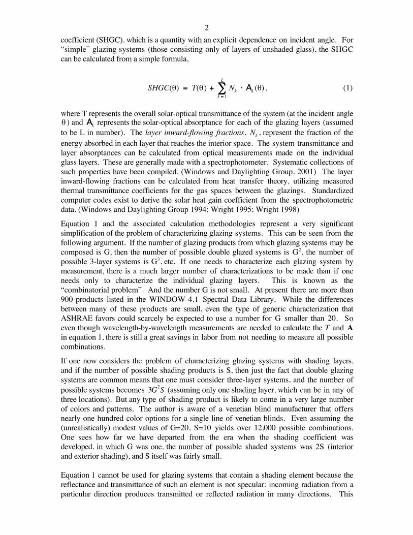
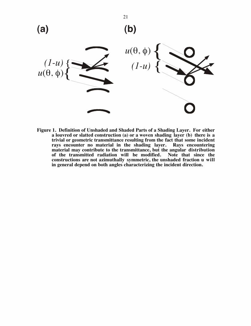
5Let us first exclude a trivial case that would otherwise complicate the discussion. Mostshading layers, being inhomogeneous, have regions for which radiation reaching the layerpass through without encountering the material of the shading at all, as illustrated in Figure1. We shall term these regions “gaps” in the shading layer. Figure 1(a) depicts a venetianblind, for which some radiation may pass between the slats; Figure 1(b) depicts a wovenmaterial for which some of the radiation passes between the threads. (It is assumed that thedistance between the threads is very large compared with the wavelength of the radiation.)In both cases, the radiation has essentially passed through an unshaded system. We dividethe glazing area into a fraction, u(θ, φ) , for which the radiation may pass through the entiresystem without encountering any shading material, and the remainder, 1 − u(θ, φ) , forwhich this is not the case. Then for a total glazed area A0 the area A0u(θ, φ) can be treatedas an unshaded glazing and Equation 1 applied, and we can restrict our attention to thereduced shading areaAG = A0 1 − u(θ, φ)( ) , for which the shading is involved in anessential way. (We note that interreflections between the shading layer and the glazingbreak down this neat separation, a point we will discuss below.)
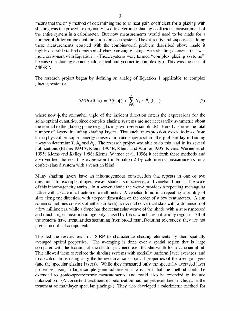
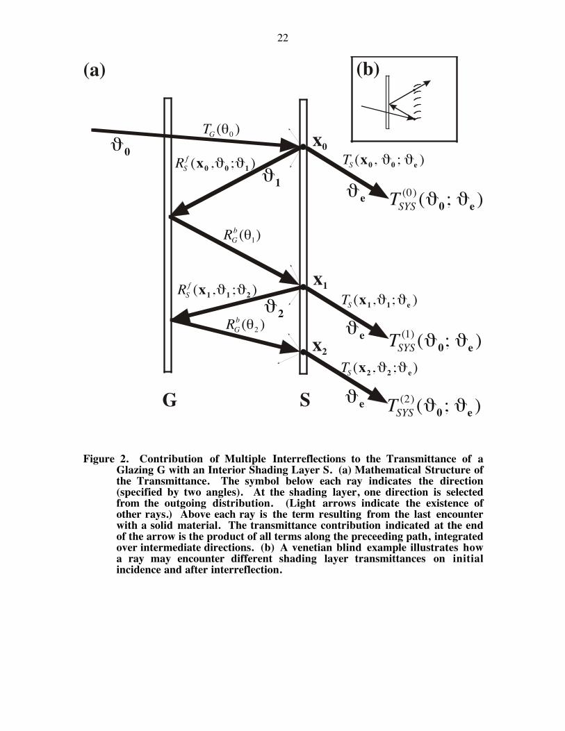
Consider the system shown in Figure 2(a). Radiation is incident on this system from adirection ϑ 0 = (θ0 , φ0 ) , (a vector) and we consider radiation that passes through theglazing system G and strikes the shading layer at x0 (a position vector, x0 = (x0, y0 ) ,assuming that the z-axis of a three-dimensional coordinate system is chosen perpendicularto the glazing plane). If the incident irradiance is E0, then the irradiance at x0 will beE0TG(θ0 ) . The total amount of radiation passing through the shading layer S and emergingin the direction ϑ e = (θe, φe) will be given by
ISYS(0) (ϑ 0;ϑ e) = E0TG(θ0 )TS (x0,ϑ0;ϑe)d
2x0∫ , (3)
where the superscript indicates that no interreflections between the layers have yet beenincluded in the calculation. The quantity TS(x0, ϑ 0; ϑ e) is the bidirectional fronttransmittance of the shading layer S at the point x0 . [We have omitted any qualifyingnotation to distinguish between front and back transmittance here because in this section wewill only use the front transmittance of the shading layer. Note, however, that unlikespecular glazings, bidirectional transmittances are not symmetric; ratherTS
f (x,ϑ1 ;ϑ2 ) = TSb (x, ϑ2;ϑ1) , where the superscripts f and b denote front and back
incidence.] This quantity can be converted to an expression for the system transmittance(neglecting interreflections) by dividing by the incident energy:
TSYS(0) (ϑ0; ϑe) =
1AG
TG (θ0 )TS(x0 , ϑ0 ; ϑe )d2x0∫ (3a)
In addition, radiation at point x0 may be reflected by the shading layer, re-reflected by theglazing, and re-incident on the shading layer at point x1 , as indicated in the figure. Theradiation that is then transmitted by the shading layer and emerges in the direction ϑ e willbe
6
TSYS(1) (ϑ 0;ϑe ) =
1AG
TG(θ0 ) RSf (x0 ,ϑ0 ;ϑ1 )RG
b (θ1)TS (x1,ϑ1;ϑe)cos(θ1)dΩ1∫[ ]d2x0∫ (4)
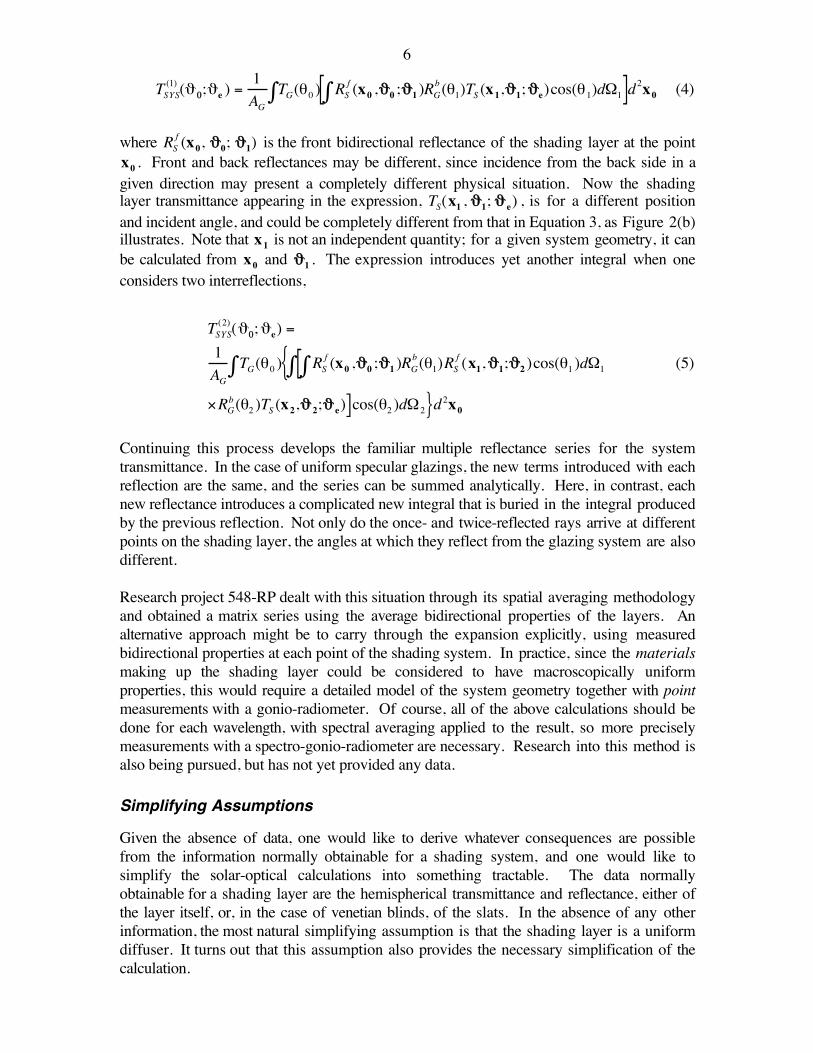
where RSf (x0, ϑ0; ϑ1) is the front bidirectional reflectance of the shading layer at the point
x0 . Front and back reflectances may be different, since incidence from the back side in agiven direction may present a completely different physical situation. Now the shadinglayer transmittance appearing in the expression, TS(x1 , ϑ1; ϑ e) , is for a different positionand incident angle, and could be completely different from that in Equation 3, as Figure 2(b)illustrates. Note that x1 is not an independent quantity; for a given system geometry, it canbe calculated from x0 and ϑ1 . The expression introduces yet another integral when oneconsiders two interreflections,
TSYS(2) (ϑ0;ϑe) =1AG
TG(θ0 ) RSf (x0 ,ϑ0 ;ϑ1 )RG
b (θ1)RSf (x1,ϑ1;ϑ2 )cos(θ1 )dΩ1∫[∫{∫
×RGb (θ2 )TS (x2,ϑ 2;ϑ e)]cos(θ2 )dΩ2}d2x0
(5)
Continuing this process develops the familiar multiple reflectance series for the systemtransmittance. In the case of uniform specular glazings, the new terms introduced with eachreflection are the same, and the series can be summed analytically. Here, in contrast, eachnew reflectance introduces a complicated new integral that is buried in the integral producedby the previous reflection. Not only do the once- and twice-reflected rays arrive at differentpoints on the shading layer, the angles at which they reflect from the glazing system are alsodifferent.
Research project 548-RP dealt with this situation through its spatial averaging methodologyand obtained a matrix series using the average bidirectional properties of the layers. Analternative approach might be to carry through the expansion explicitly, using measuredbidirectional properties at each point of the shading system. In practice, since the materialsmaking up the shading layer could be considered to have macroscopically uniformproperties, this would require a detailed model of the system geometry together with pointmeasurements with a gonio-radiometer. Of course, all of the above calculations should bedone for each wavelength, with spectral averaging applied to the result, so more preciselymeasurements with a spectro-gonio-radiometer are necessary. Research into this method isalso being pursued, but has not yet provided any data.
Simplifying Assumptions
Given the absence of data, one would like to derive whatever consequences are possiblefrom the information normally obtainable for a shading system, and one would like tosimplify the solar-optical calculations into something tractable. The data normallyobtainable for a shading layer are the hemispherical transmittance and reflectance, either ofthe layer itself, or, in the case of venetian blinds, of the slats. In the absence of any otherinformation, the most natural simplifying assumption is that the shading layer is a uniformdiffuser. It turns out that this assumption also provides the necessary simplification of thecalculation.
7
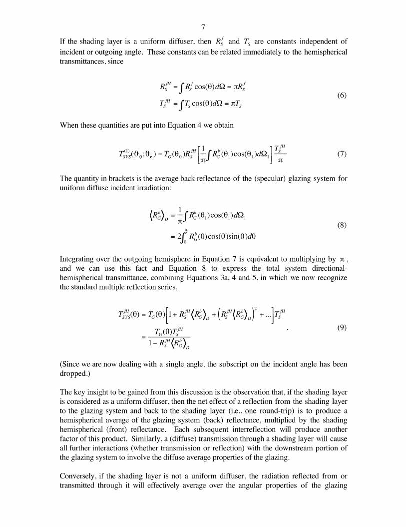
If the shading layer is a uniform diffuser, then RSf and TS are constants independent of
incident or outgoing angle. These constants can be related immediately to the hemisphericaltransmittances, since
RSfH = RS
f cos(θ)dΩ∫ = πRSf
TSfH = TS cos(θ)dΩ∫ = πTS(6)
When these quantities are put into Equation 4 we obtain
TSYS(1) (ϑ 0;ϑe ) = TG(θ0 )RS
fH 1π
RGb (θ1)cos(θ1 )dΩ1∫
TSfH
π(7)
The quantity in brackets is the average back reflectance of the (specular) glazing system foruniform diffuse incident irradiation:
RGb D=1π
RGb (θ1)cos(θ1)dΩ1∫
= 2 RGb (θ0
π2
∫ )cos(θ)sin(θ)dθ(8)
Integrating over the outgoing hemisphere in Equation 7 is equivalent to multiplying by π ,and we can use this fact and Equation 8 to express the total system directional-hemispherical transmittance, combining Equations 3a, 4 and 5, in which we now recognizethe standard multiple reflection series,
TSYSfH (θ) = TG(θ) 1+ RS
fH RGb
D+ RS
fH RGb
D( )2 + ...
TS
fH
=TG(θ)TSfH
1− RSfH RGb D
. (9)
(Since we are now dealing with a single angle, the subscript on the incident angle has beendropped.)
The key insight to be gained from this discussion is the observation that, if the shading layeris considered as a uniform diffuser, then the net effect of a reflection from the shading layerto the glazing system and back to the shading layer (i.e., one round-trip) is to produce ahemispherical average of the glazing system (back) reflectance, multiplied by the shadinghemispherical (front) reflectance. Each subsequent interreflection will produce anotherfactor of this product. Similarly, a (diffuse) transmission through a shading layer will causeall further interactions (whether transmission or reflection) with the downstream portion ofthe glazing system to involve the diffuse average properties of the glazing.
Conversely, if the shading layer is not a uniform diffuser, the radiation reflected from ortransmitted through it will effectively average over the angular properties of the glazing
8system in a different way. This means that if the uniform diffuser assumption for theshading layer fails, the effect could be large or small, depending on the glazing systemcharacteristics.
APPROXIMATE ANALYSIS OF SHADED GLAZING SYSTEMS
The conclusions of the previous section allow us to calculate the approximate properties forany type of shaded glazing, but before doing so it will be necessary to introduce somenotation. We shall consider glazings consisting of one shading layer, which we denote byS, and some number L of transparent layers. So in general we shall be discussing a systemof L+1 layers. We will number these layers sequentially from outside to inside, so that wecan refer to a specific layer by its position, n, in the assembly. If we removed a particularlayer, n, from the assembly and measured its solar-optical properties in isolation, theresulting transmission, reflectance and absorption would be denoted Tn , Rn , and An .
These quantities depend on a number of physical variables. All depend on the incidentdirection, the wavelength of the radiation, and the polarization state of the radiation enteringthem. The wavelength and polarization dependence will not be noted explicitly here. Inprinciple, all of the equations to follow should be calculated for each wavelength andpolarization, and the final result averaged over the polarization and wavelength spectrum ofthe incident radiation. In practice, however, because of the limited availability ofcharacterization data, polarizations are typically averaged for each layer (assumingunpolarized incident radiation). For shading layers, a similar lack of data leads to use ofwavelength-averaged layer properties. Neither practice is strictly correct.
In the discussion below, in order to avoid rewriting equations for special cases, it willsometimes happen that impossible combinations of indices appear in the equations, i.e.,indices that refer to a nonexistent layer. For example, if the first layer of the system is layer1 (and we have not defined a layer 0, as will occasionally happen below), then reference to alayer k-1 becomes nonsensical for k=1. This possibility will particularly arise in thediscussion of layer absorptances. We deal with these cases by defining all nonexistentlayers to have T=1, R=0, and A=0.
As noted above, for specular glazings the solar-optical properties will depend on the incidentangle, e.g., Tn(θ) , while for a shading layer it is a bidirectional quantity, e.g., Tn(ϑi ; ϑe ) forthe incident (i) and emerging (e) directions, each of which is specified by a pair of angles.In addition, the properties of the layer depend on the side of the layer on which the radiationis incident. We shall denote this by the superscripts f (“front”, for radiation coming fromthe outside) and b (“back”, for radiation coming from the inside), e.g., Tn
f (ϑi ; ϑ e) . (Toavoid confusion with exponentiation, all quantities raised to a power will be enclosed inparentheses.) As noted above, for specular layers (or systems) it is always true thatTn
f (θ) = Tnb (θ) ≡ Tn (θ) , so that we can drop the superscript, but this is not the case for
Rnf (θ) and An
f (θ) . For nonspecular layers the analogous relation isTn
f (ϑi ; ϑ e) = Tnb (ϑ e; ϑi ) . We shall also use the superscript H to denote a directional-
hemispherical quantity, i.e., a bidirectional one summed over the outgoing direction, e.g.,
9
TnfH (ϑi ) = Tn
f (ϑi ; ϑe )d2ϑ e
hemisphere∫∫ . Note that for a purely specular layer this operation
does nothing, since outgoing radiation only occurs in a single direction: TnH(θ) ≡ Tn (θ) .
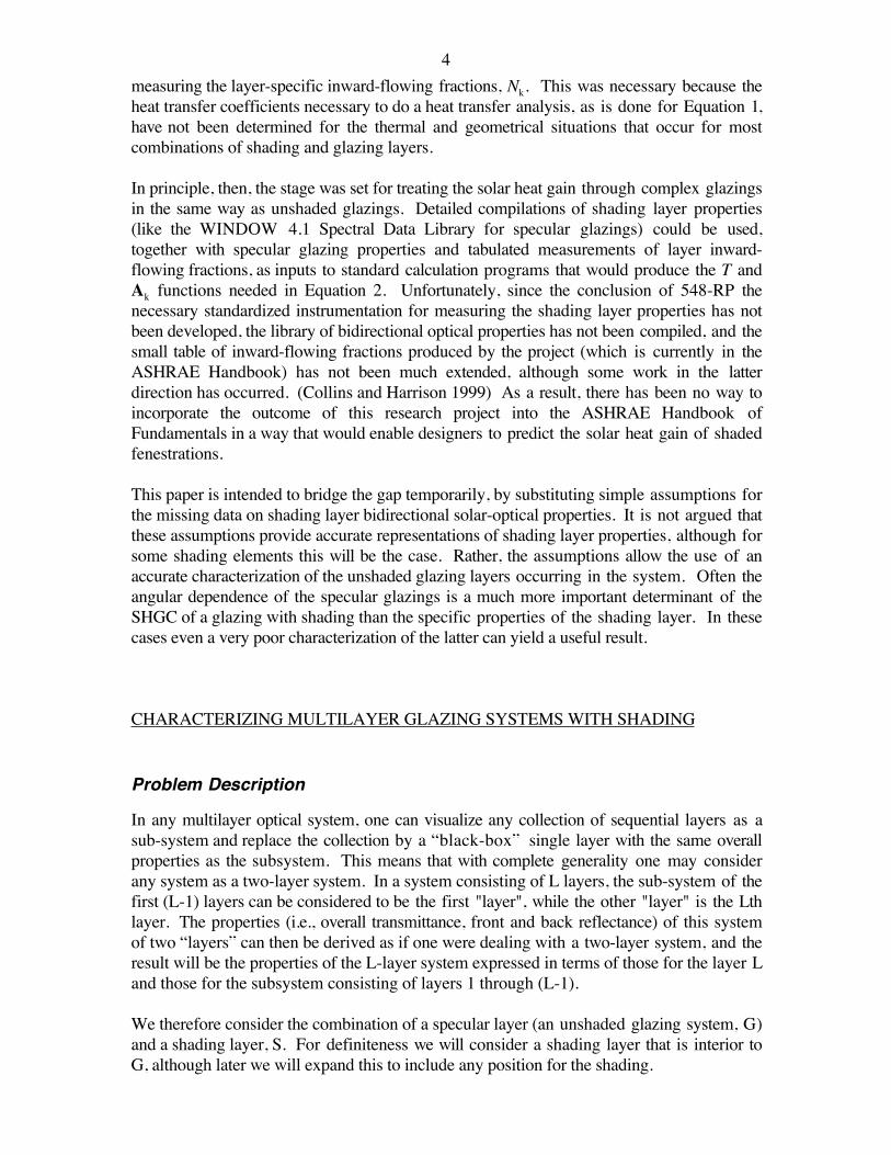
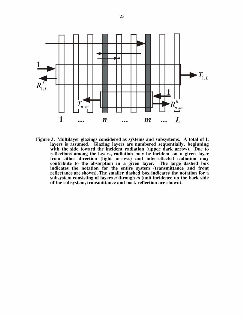
As also noted above, adjacent layers can be collected together and considered as systems.The notation for this is summarized in Figure 3, and consists of using as subscripts thelayer numbers of the first and last layers in the system to identify the overall systemproperties. It is important to distinguish that these are different from the isolated layerproperties. For example,
€
Rm,nf gives the fraction of the radiation incident on layer m that is
reflected, and includes multiple interreflections among layers m through n, but none fromlayers lying to the inside of (i.e., with a number larger than) layer n. (Of course,Rn, n
f ≡ Rnf .) This fact necessitates additional notation for specifying layer absorptions.
Consider a (sub)system consisting of the layers m through n. This system has anabsorptance,
€
Am, nf = 1 − Tm, n
f − Rm, nf . However, the absorptance actually takes place in the
individual layers of the system and we denote this layer absorptance within a system by
Ak ; m, n( )f for the kth layer. We note that the quantity Ak appearing in Equations 1 and 2
should be denoted more correctly Ak ;(1,L)f . They are not isolated-layer absorptances, but
rather layer absorptances within the system of layers 1 through L. Absorptance in the layerk comes from radiation incident both on its front surface and on its back surface (due tomultiple reflectance from downstream layers). The superscript f denotes that this absorptionis all due to radiation incident on the front side of layer m.
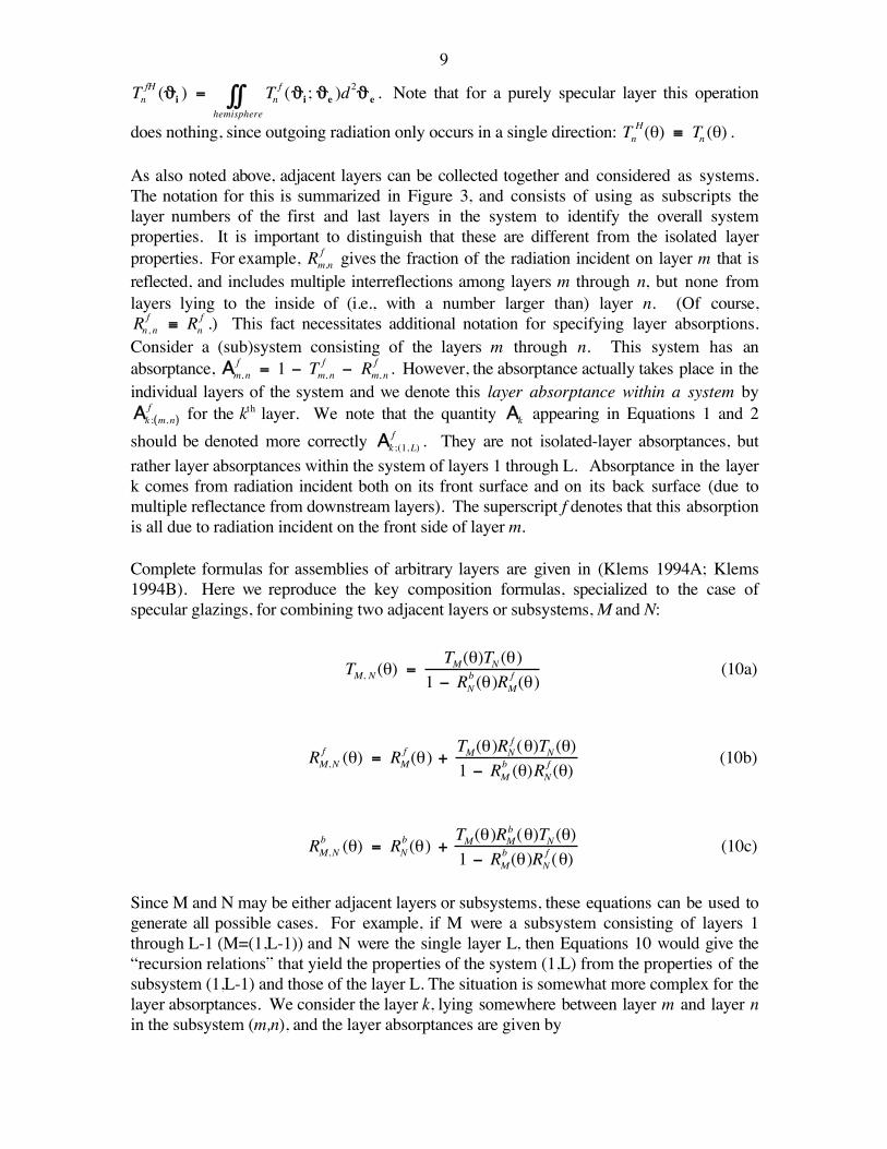
Complete formulas for assemblies of arbitrary layers are given in (Klems 1994A; Klems1994B). Here we reproduce the key composition formulas, specialized to the case ofspecular glazings, for combining two adjacent layers or subsystems, M and N:
TM, N (θ) =TM(θ)TN (θ)
1 − RNb (θ)RM
f (θ)(10a)
RM,Nf (θ) = RM
f (θ) + TM(θ)RNf (θ)TN (θ)1 − RM
b (θ)RNf (θ)
(10b)
RM,Nb (θ) = RN
b (θ) + TM(θ)RMb (θ)TN (θ)1 − RM
b (θ)RNf (θ)
(10c)
Since M and N may be either adjacent layers or subsystems, these equations can be used togenerate all possible cases. For example, if M were a subsystem consisting of layers 1through L-1 (M=(1,L-1)) and N were the single layer L, then Equations 10 would give the“recursion relations” that yield the properties of the system (1,L) from the properties of thesubsystem (1,L-1) and those of the layer L. The situation is somewhat more complex for thelayer absorptances. We consider the layer k, lying somewhere between layer m and layer nin the subsystem (m,n), and the layer absorptances are given by
10
Ak ;(m, n)
f (θ) =Tm, k −1(θ)Ak
f (θ)1 − Rm , k− 1
b (θ)Rk, nf (θ)
+Tm, k (θ)Rk + 1, nf (θ)Ak
b (θ)1 − Rm, k
b (θ)Rk +1, nf (θ)
(11a)
Ak ;(m, n)
b (θ) =Tk +1, n (θ)Ak
b(θ)1 − Rm , k
b (θ)Rk +1, nf (θ)
+Tk ,m(θ)Rm, k− 1b (θ)Ak
f (θ)1 − Rm, k −1
b (θ)Rk ,nf (θ)
. (11b)
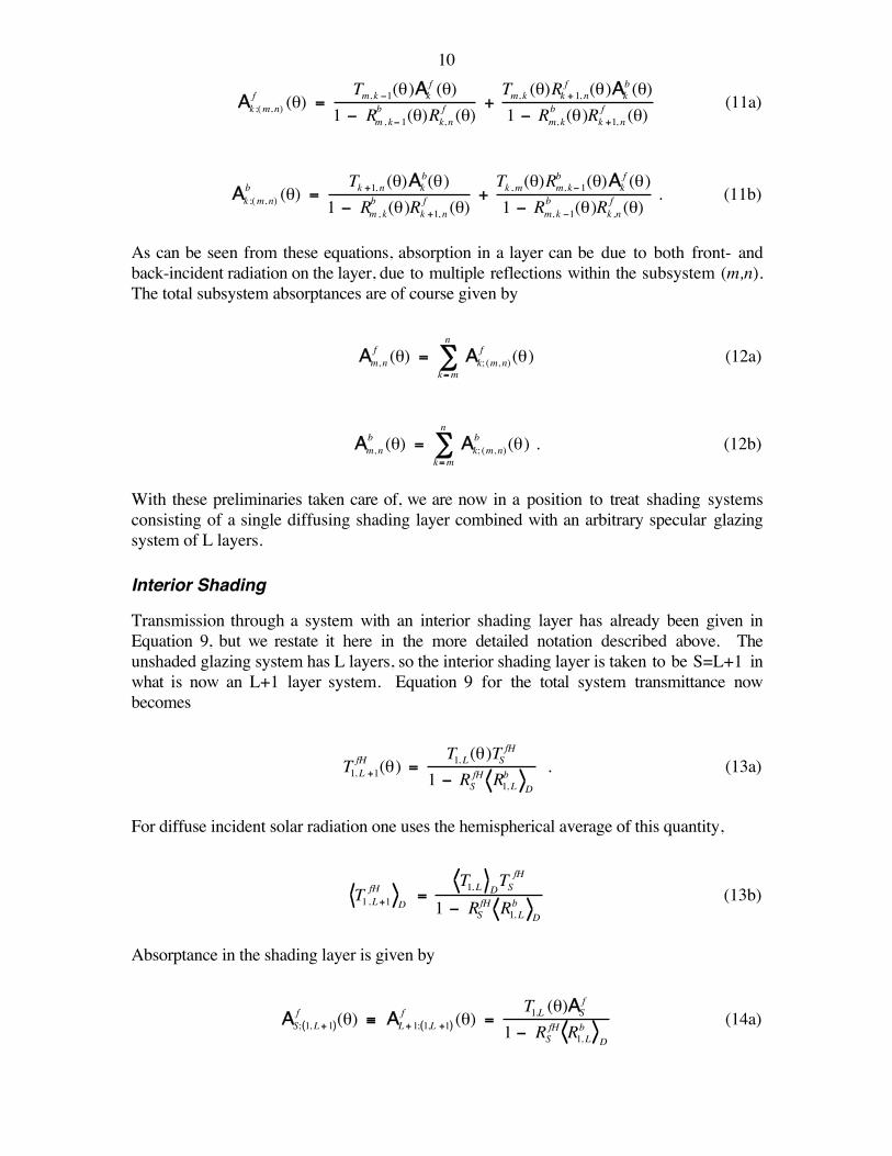
As can be seen from these equations, absorption in a layer can be due to both front- andback-incident radiation on the layer, due to multiple reflections within the subsystem (m,n).The total subsystem absorptances are of course given by
Am, n
f (θ) = Ak; (m, n)f (θ)
k=m
n
∑ (12a)
Am, n
b (θ) = Ak; (m, n)b (θ)
k=m
n
∑ . (12b)
With these preliminaries taken care of, we are now in a position to treat shading systemsconsisting of a single diffusing shading layer combined with an arbitrary specular glazingsystem of L layers.
Interior Shading
Transmission through a system with an interior shading layer has already been given inEquation 9, but we restate it here in the more detailed notation described above. Theunshaded glazing system has L layers, so the interior shading layer is taken to be S=L+1 inwhat is now an L+1 layer system. Equation 9 for the total system transmittance nowbecomes
T1, L +1fH (θ) =
T1, L(θ)TSfH
1 − RSfH R1, Lb D
. (13a)
For diffuse incident solar radiation one uses the hemispherical average of this quantity,
T1,L+1fH
D=
T1, L DTS
fH
1 − RSfH R1, Lb D
(13b)
Absorptance in the shading layer is given by
€
AS; 1, L+ 1( )f (θ) ≡ AL+ 1; 1,L +1( )
f (θ) =T1,L (θ)AS
f
1 − RSfH R1, Lb D
(14a)
11while for other layers (1 ≤ k ≤ L ) the absorptance can be expressed in terms of theabsorptance for the unshaded L-layer system, which may be computed from Equation 11a:
€
Ak; 1,L +1( )f (θ) = Ak ; 1,L( )
f (θ) + Ak; 1,L( )b
D
T1,L (θ)RSfH
1 − RSfH R1, Lb D
(14b)
The hemispherical averaging of these quantities is straightforward:
€
AS; 1,L +1( )f
D=
T1,L DAS
f
1 − RSfH R1, Lb D
(14c)
€
Ak ; 1, L+ 1( )f
D= Ak; 1,L( )
f
D+ Ak ; 1,L( )
b
D
T1, L DRSfH
1 − RSfH R1,Lb D
(14d)
These equations apply to the reduced shading area of the glazing, AG . The correspondingunshaded glazing system properties should be applied to the unshaded area, u(θ, φ)A0 .
Putting Equation 2 into the present notation, the solar heat gain coefficient for the shadedarea of the overall system is
€
SHGC1,L +1shaded (θ) = T1,L +1
fH (θ) + Nk ⋅ Ak ;(1,L +1)f (θ)
k =1
L+ 1
∑ (15a)
which becomes, after combining the expression with Equations 13 and 14,
€
SHGC1,L +1shaded (θ) =
T1,L (θ) ⋅ TSfH + NL +1 ⋅ ASf + RSfH Nk ⋅ Ak; 1, L( )
b
Dk= 1
L
∑
1 − RSfH R1,Lb D
+ Nk ⋅ Ak ; 1, L( )f (θ)
k =1
L
∑
, (15b)
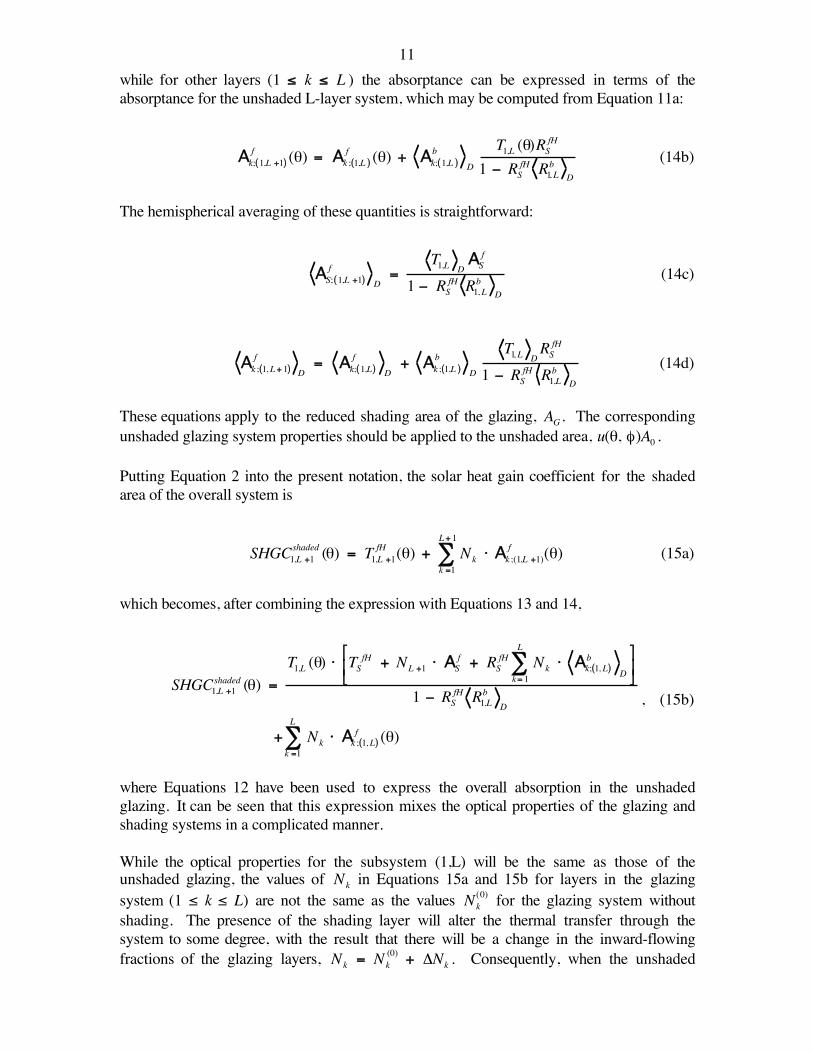
where Equations 12 have been used to express the overall absorption in the unshadedglazing. It can be seen that this expression mixes the optical properties of the glazing andshading systems in a complicated manner.
While the optical properties for the subsystem (1,L) will be the same as those of theunshaded glazing, the values of
€
Nk in Equations 15a and 15b for layers in the glazingsystem (1 ≤ k ≤ L) are not the same as the values
€
Nk(0) for the glazing system without
shading. The presence of the shading layer will alter the thermal transfer through thesystem to some degree, with the result that there will be a change in the inward-flowingfractions of the glazing layers,
€
Nk = Nk(0) + ΔNk . Consequently, when the unshaded
12equivalents of Equations 14 are put into Equation 2, the result is not exactly the solar heatgain coefficient of the unshaded glazing. Instead we obtain
€
SHGC1,L +1unshaded (θ) = SHGC1,L (θ) + ΔNkAk;(1,L )
f (θ)k= 1
L
∑ (15c)
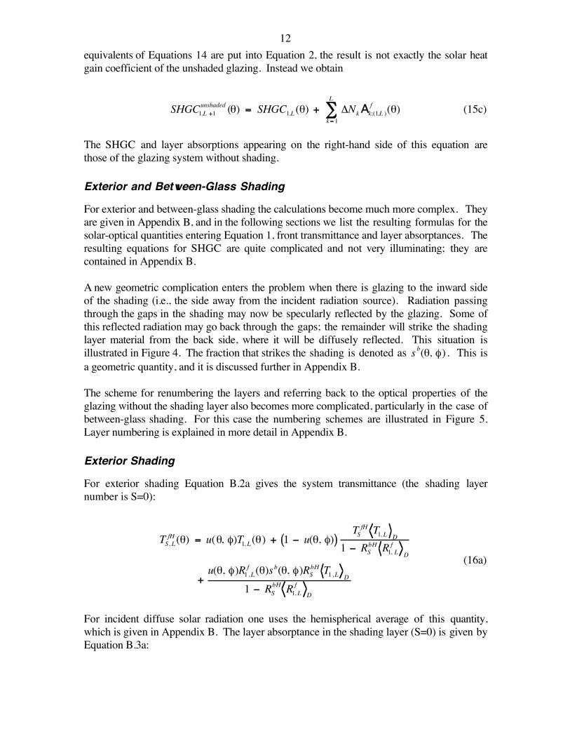
The SHGC and layer absorptions appearing on the right-hand side of this equation arethose of the glazing system without shading.
Exterior and Between-Glass Shading
For exterior and between-glass shading the calculations become much more complex. Theyare given in Appendix B, and in the following sections we list the resulting formulas for thesolar-optical quantities entering Equation 1, front transmittance and layer absorptances. Theresulting equations for SHGC are quite complicated and not very illuminating; they arecontained in Appendix B.
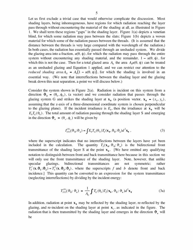
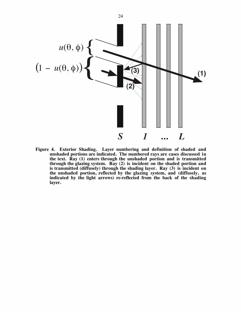
A new geometric complication enters the problem when there is glazing to the inward sideof the shading (i.e., the side away from the incident radiation source). Radiation passingthrough the gaps in the shading may now be specularly reflected by the glazing. Some ofthis reflected radiation may go back through the gaps; the remainder will strike the shadinglayer material from the back side, where it will be diffusely reflected. This situation isillustrated in Figure 4. The fraction that strikes the shading is denoted as s b(θ, φ) . This isa geometric quantity, and it is discussed further in Appendix B.
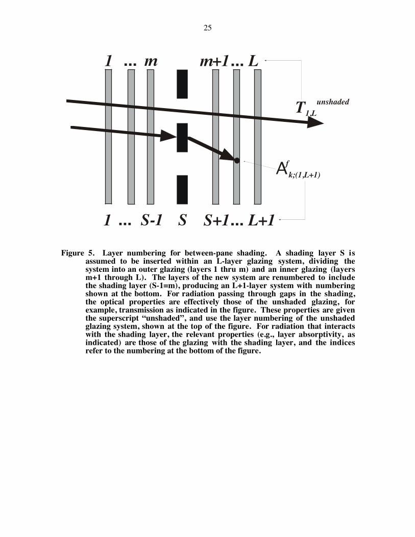
The scheme for renumbering the layers and referring back to the optical properties of theglazing without the shading layer also becomes more complicated, particularly in the case ofbetween-glass shading. For this case the numbering schemes are illustrated in Figure 5.Layer numbering is explained in more detail in Appendix B.
Exterior Shading
For exterior shading Equation B.2a gives the system transmittance (the shading layernumber is S=0):
TS, LfH (θ) = u(θ, φ)T1, L(θ) + 1 − u(θ, φ)( )TSfH T1, L D
1 − RSbH R1, Lf D
+u(θ, φ)R1,Lf (θ)sb(θ, φ)RSbH T1,L D
1 − RSbH R1, L
fD
(16a)
For incident diffuse solar radiation one uses the hemispherical average of this quantity,which is given in Appendix B. The layer absorptance in the shading layer (S=0) is given byEquation B.3a:
13
AS;(S, L )f (θ) = 1 − u(θ, φ)( ) AS
f +ASbR1, Lf (θ)
1 − RSbH R1, L
fD
+u(θ, φ)R1, Lf (θ)sb(θ, φ)AS
b
1 − RSbH R1, Lf D
(16b)
and for the other layers (1 ≤ k ≤ L ) the layer absorptances are expressed in terms of thelayer absorptances of the unshaded system in Equation B.3b:
Ak ;(S, L )f (θ) = u(θ, φ)Ak; (1, L)
f (θ) + 1 − u(θ, φ)( )TS
fH Ak ;(1,L)f
D
1 − RSbH R1, Lf D
+u(θ, φ)R1,Lf (θ)sb(θ, φ)RSbH Ak ;( 1, L )
fD
1 − RSbH R1, Lf D
. (16c)
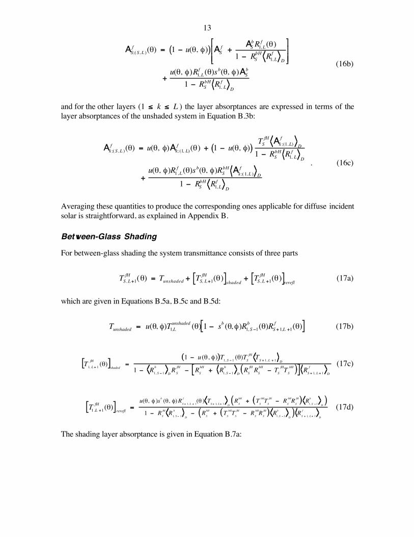
Averaging these quantities to produce the corresponding ones applicable for diffuse incidentsolar is straightforward, as explained in Appendix B.
Between-Glass Shading
For between-glass shading the system transmittance consists of three parts
TS, L+1fH (θ) = Tunshaded + TS, L+1
fH (θ)[ ]shaded + TS, L +1fH (θ)[ ]rerefl (17a)
which are given in Equations B.5a, B.5c and B.5d:
€
Tunshaded = u(θ, φ)T1,Lunshaded (θ) 1 − sb (θ, φ)R1, S −1
b (θ)RS + 1,L +1f (θ)[ ] (17b)
€
T1, L + 1
fH (θ)[ ]shaded
=1 − u (θ, φ)( )T1, S − 1 (θ)TS
fH TS + 1, L + 1 D
1 − R1, S − 1b
DRS
fH− RS
bH+ R1, S − 1
b
DRS
fH RS
bH− TS
fHTS
bH( )[ ] RS + 1, L + 1
f
D
(17c)
€
T1 ,L +1fH (θ)[ ] rerefl =
u(θ, φ )sb (θ, φ)RS + 1, L + 1
f (θ ) TS + 1, L + 1 D
RS
bH + TS
bHTS
fH − RS
bHRS
fH( ) R1, S − 1
b
D( )
1 − RS
fH R1, S − 1
b
D− R
S
bH + TS
bHTS
fH − RS
bHRS
fH( ) R1, S − 1
b
D( ) R
S + 1, L + 1
f
D
(17d)
The shading layer absorptance is given in Equation B.7a:
14
€
AS; (1,L + 1)f =
1 − u (θ, φ)( )T1, S − 1 (θ)ASf
1 − R1, S − 1bH
DRS, L + 1
fH
D
+u(θ, φ)T1, S − 1 (θ)RS + 1, L + 1
f (θ)sb (θ , φ) + 1 − u (θ , φ)( )T1, SfH (θ) RS + 1, L + 1
fH
D[ ]AS: (1, S)b
1 − R1,SbH
DRS + 1, L + 1
f
D
(17e)
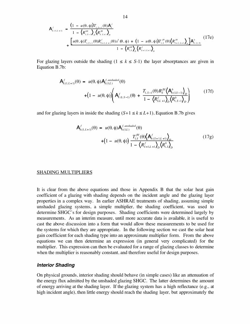
For glazing layers outside the shading (1 ≤ k ≤ S-1) the layer absorptances are given inEquation B.7b:
€
Ak;(1, L+ 1)f (θ) = u(θ, φ)Ak;(1,L )
f , unshaded(θ)
+ 1 − u(θ, φ)( ) Ak :(1, S −1)f (θ) +
T1, S −1(θ)RSfH Ak:(1,S − 1)b
D
1 − RS,L +1f
DR1, S −1b
D
(17f)
and for glazing layers in inside the shading (S+1 ≤ k ≤ L+1), Equation B.7b gives
€
Ak;(1, L+ 1)f (θ) = u(θ, φ)Ak;(1,L )
f , unshaded(θ)
+ 1 − u(θ, φ)( )T1, S
fH (θ) Ak:(S + 1,L +1)f
D
1 − RS +1,L +1f
DR1, Sb
D
(17g)
SHADING MULTIPLIERS
It is clear from the above equations and those in Appendix B that the solar heat gaincoefficient of a glazing with shading depends on the incident angle and the glazing layerproperties in a complex way. In earlier ASHRAE treatments of shading, assuming simpleunshaded glazing systems, a simple multiplier, the shading coefficient, was used todetermine SHGC’s for design purposes. Shading coefficients were determined largely bymeasurements. As an interim measure, until more accurate data is available, it is useful tocast the above discussion into a form that would allow these measurements to be used forthe systems for which they are appropriate. In the following section we cast the solar heatgain coefficient for each shading type into an approximate multiplier form. From the aboveequations we can then determine an expression (in general very complicated) for themultiplier. This expression can then be evaluated for a range of glazing classes to determinewhen the multiplier is reasonably constant, and therefore useful for design purposes.
Interior Shading
On physical grounds, interior shading should behave (in simple cases) like an attenuation ofthe energy flux admitted by the unshaded glazing SHGC. The latter determines the amountof energy arriving at the shading layer. If the glazing system has a high reflectance (e.g., athigh incident angle), then little energy should reach the shading layer, but approximately the
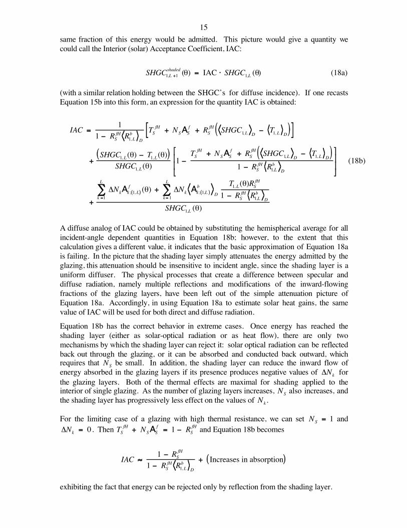
15same fraction of this energy would be admitted. This picture would give a quantity wecould call the Interior (solar) Acceptance Coefficient, IAC:
€
SHGC1,L +1shaded (θ) = IAC ⋅ SHGC1,L (θ) (18a)
(with a similar relation holding between the SHGC’s for diffuse incidence). If one recastsEquation 15b into this form, an expression for the quantity IAC is obtained:
€
IAC =1
1 − RSfH R1, Lb D
TSfH + NSAS
f + RSfH SHGC1, L D
− T1, L D( )[ ]
+SHGC1, L(θ) − T1, L(θ)( )
SHGC1, L(θ)1 −
TSfH + NSAS
f + RSfH SHGC1, L D
− T1, L D( )1 − RSfH R1,Lb D
+
ΔNkAk ; 1, L( )f (θ)
k =1
L
∑ + ΔNk Ak ; 1,L( )b
Dk= 1
L
∑T1, L(θ)RSfH
1 − RSfH R1,Lb D
SHGC1,L (θ)
(18b)
A diffuse analog of IAC could be obtained by substituting the hemispherical average for allincident-angle dependent quantities in Equation 18b; however, to the extent that thiscalculation gives a different value, it indicates that the basic approximation of Equation 18ais failing. In the picture that the shading layer simply attenuates the energy admitted by theglazing, this attenuation should be insensitive to incident angle, since the shading layer is auniform diffuser. The physical processes that create a difference between specular anddiffuse radiation, namely multiple reflections and modifications of the inward-flowingfractions of the glazing layers, have been left out of the simple attenuation picture ofEquation 18a. Accordingly, in using Equation 18a to estimate solar heat gains, the samevalue of IAC will be used for both direct and diffuse radiation.
Equation 18b has the correct behavior in extreme cases. Once energy has reached theshading layer (either as solar-optical radiation or as heat flow), there are only twomechanisms by which the shading layer can reject it: solar optical radiation can be reflectedback out through the glazing, or it can be absorbed and conducted back outward, whichrequires that
€
NS be small. In addition, the shading layer can reduce the inward flow ofenergy absorbed in the glazing layers if its presence produces negative values of
€
ΔNk forthe glazing layers. Both of the thermal effects are maximal for shading applied to theinterior of single glazing. As the number of glazing layers increases,
€
NS also increases, andthe shading layer has progressively less effect on the values of
€
Nk.
For the limiting case of a glazing with high thermal resistance, we can set
€
NS = 1 and
€
ΔNk = 0 . Then
€
TSfH + NSAS
f = 1 − RSfH and Equation 18b becomes
€
IAC ≈1 − RS
fH
1 − RSfH R1, Lb
D
+ Increases in absorption( )
exhibiting the fact that energy can be rejected only by reflection from the shading layer.
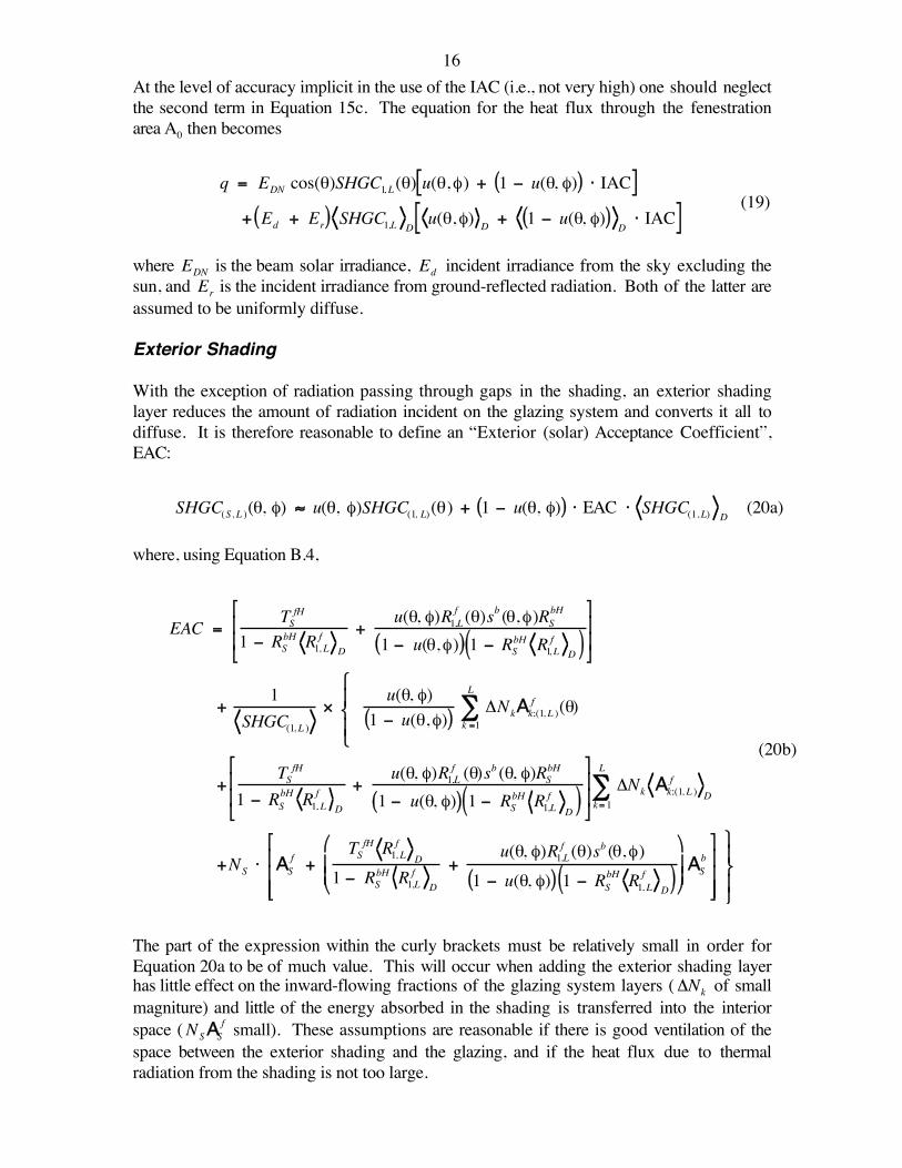
16At the level of accuracy implicit in the use of the IAC (i.e., not very high) one should neglectthe second term in Equation 15c. The equation for the heat flux through the fenestrationarea A0 then becomes
€
q = EDN cos(θ)SHGC1, L(θ) u(θ,φ) + 1 − u(θ, φ)( ) ⋅ IAC[ ]+ Ed + Er( ) SHGC1,L D
u(θ,φ) D + 1 − u(θ, φ)( )D⋅ IAC[ ]
(19)
where
€
EDN is the beam solar irradiance,
€
Ed incident irradiance from the sky excluding thesun, and
€
Er is the incident irradiance from ground-reflected radiation. Both of the latter areassumed to be uniformly diffuse.
Exterior Shading
With the exception of radiation passing through gaps in the shading, an exterior shadinglayer reduces the amount of radiation incident on the glazing system and converts it all todiffuse. It is therefore reasonable to define an “Exterior (solar) Acceptance Coefficient”,EAC:
SHGC(S, L )(θ, φ) ≈ u(θ, φ)SHGC(1, L)(θ) + 1 − u(θ, φ)( ) ⋅ EAC ⋅ SHGC(1,L) D(20a)
where, using Equation B.4,
€
EAC =TSfH
1 − RSbH R1, Lf D
+u(θ, φ)R1,L
f (θ)sb (θ,φ)RSbH
1 − u(θ,φ)( ) 1 − RSbH R1, Lf D( )
+1
SHGC(1, L )×
u(θ, φ)1 − u(θ,φ)( ) ΔNkAk;(1, L )
f (θ)k =1
L
∑
+TSfH
1 − RSbH R1, L
fD
+u(θ, φ)R1,Lf (θ)sb (θ, φ)RSbH
1 − u(θ, φ)( ) 1 − RSbH R1,Lf D( )
ΔNk Ak;(1, L )f
Dk= 1
L
∑
+NS ⋅ ASf +
TSfH R1, Lf D
1 − RSbH R1,Lf D
+u(θ, φ)R1,Lf (θ)sb (θ,φ)
1 − u(θ, φ)( ) 1 − RSbH R1, L
fD( )
AS
b
(20b)
The part of the expression within the curly brackets must be relatively small in order forEquation 20a to be of much value. This will occur when adding the exterior shading layerhas little effect on the inward-flowing fractions of the glazing system layers (
€
ΔNk of smallmagniture) and little of the energy absorbed in the shading is transferred into the interiorspace (
€
NSASf small). These assumptions are reasonable if there is good ventilation of the
space between the exterior shading and the glazing, and if the heat flux due to thermalradiation from the shading is not too large.
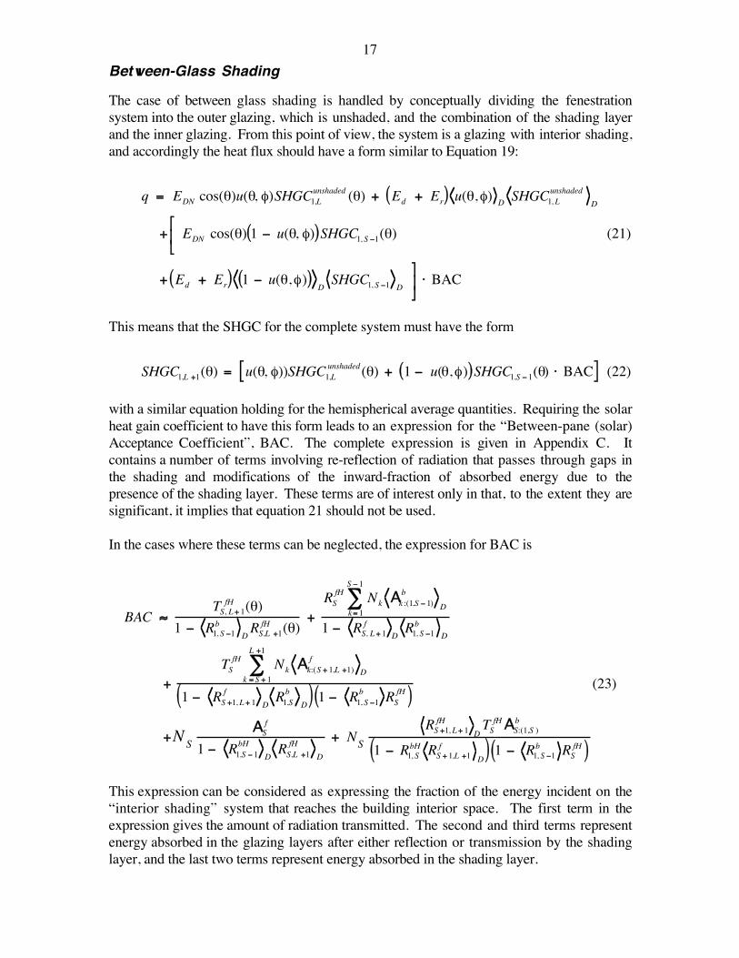
17Between-Glass Shading
The case of between glass shading is handled by conceptually dividing the fenestrationsystem into the outer glazing, which is unshaded, and the combination of the shading layerand the inner glazing. From this point of view, the system is a glazing with interior shading,and accordingly the heat flux should have a form similar to Equation 19:
€
q = EDN cos(θ)u(θ, φ)SHGC1,Lunshaded (θ) + Ed + Er( ) u(θ,φ) D SHGC1, L
unshadedD
+
EDN cos(θ) 1 − u(θ, φ)( )SHGC1, S −1(θ)
+ Ed + Er( ) 1 − u(θ,φ)( )DSHGC1, S −1 D
⋅ BAC
(21)
This means that the SHGC for the complete system must have the form
€
SHGC1,L +1(θ) = u(θ, φ))SHGC1,Lunshaded(θ) + 1 − u(θ,φ)( )SHGC1,S − 1(θ) ⋅ BAC[ ] (22)
with a similar equation holding for the hemispherical average quantities. Requiring the solarheat gain coefficient to have this form leads to an expression for the “Between-pane (solar)Acceptance Coefficient”, BAC. The complete expression is given in Appendix C. Itcontains a number of terms involving re-reflection of radiation that passes through gaps inthe shading and modifications of the inward-fraction of absorbed energy due to thepresence of the shading layer. These terms are of interest only in that, to the extent they aresignificant, it implies that equation 21 should not be used.
In the cases where these terms can be neglected, the expression for BAC is
€
BAC ≈TS, L+ 1
fH (θ)1 − R1, S −1b
DRS,L +1
fH (θ)+RS
fH Nkk= 1
S − 1
∑ Ak :(1,S − 1)b
D
1 − RS, L+ 1f
DR1, S −1b
D
+TS
fH Nkk = S + 1
L +1
∑ Ak:(S + 1,L +1)f
D
1 − RS +1, L+ 1f
DR1,Sb
D( ) 1 − R1, S −1b RS
fH( )
+NSAS
f
1 − R1,S − 1bH
DRS,L +1
fHD
+ NSRS +1, L+ 1
fHDTSfHAS:(1,S )
b
1 − R1, SbH RS + 1,L +1f
D( ) 1 − R1, S −1b RSfH( )
(23)
This expression can be considered as expressing the fraction of the energy incident on the“interior shading” system that reaches the building interior space. The first term in theexpression gives the amount of radiation transmitted. The second and third terms representenergy absorbed in the glazing layers after either reflection or transmission by the shadinglayer, and the last two terms represent energy absorbed in the shading layer.
18THE 2001 VERSION OF THE HANDBOOK OF FUNDAMENTALS
The calculations and approximations described in this paper formed the basis for updatingthe equations for solar heat gain in shaded fenestrations in the forthcoming version of theHandbook of Fundamentals. The equations given above were presented there in asomewhat simplified form. In that treatment it was assumed that
€
sb(θ,φ) = 0 , and
€
u(θ,φ) D = 0 in order to reduce the complexity of the material presented. These arelikely to be good approximations in any case. They have been relaxed here in order topresent a complete treatment that can be applied to unusual cases.
The existing tables of shading coefficients for simple systems were used to construct tablesof IAC, EAC, and BAC. The reasoning is as follows: The shading coefficient tables wereoriginally constructed from measurements, usually made at a single incident angle, and themeasured SHGC for the system was converted to shading coefficient by dividing by theSHGC for single glazing at that angle. The shading coefficient was assumed to be angle-independent, and in the shading coefficient/solar heat gain factor treatment the SHGC forstandard single glazing was contained in the solar heat gain factor, which depended onincident angle. Because the IAC, EAC and BAC characterize subsystems for which theouter layer is a uniform diffuser, they can be expected to be independent of incident angleunder the assumption
€
u(θ,φ) = 0 . This assumption was made for all of the tables exceptthat of EAC for louvered sun screens. The table value of shading coefficient was assumedto apply at normal incidence, and it was multiplied by the SHGC for standard 3mm (1/8inch) clear single glazing at normal incidence to give back the system SHGC. Equation 18a,20a or 22 was then applied with the appropriate glazing system SHGC at normal incidenceto calculate the multiplier listed in the table.
For louvered sun screens, the shading coefficient table, the profile angle, and the louverconstruction were used to calculate
€
u(θ,φ) ≡ u(ψ) (which is termed
€
Fu in the Handbook).At the largest profile angle
€
u(θ,φ) = 0 , and the shading coefficient for this profile anglewas used to calculate EAC.
The detailed formulas presented above for the multipliers will enable one to calculate whenthe assumption of a constant IAC, EAC or BAC is violated in particular systems.
CONCLUSIONS
The computational methods for calculating the properties of glazing systems containingshading from the properties of their components have been developed, but the measurementstandards and property data bases necessary to apply them have not.
In order to apply the calculations when there is very limited data, and to simplify them to alevel appropriate to a handbook treatment, a drastic simplifying assumption was necessary.This assumption is that all shading layers behave as uniform diffusers in both transmissionand reflection for radiation that in any way encounters the material of the layer.
19Many shading layers also contain gaps, through which radiation can penetrate withoutencountering the shading material, leading to the physical picture of a shaded fenestration asa mixture of a completely shaded and a completely unshaded one. This picture is valid onlywhen certain multiple reflections are negligibly small.
Complete formulas for the solar-optical properties of such shaded fenestrations have beenpresented.
Performance multipliers are defined for simple systems and may be used with appropriatecaution.
When both penetration through shading gaps and multiple reflections are significant,performance multipliers cannot be used, and the solar-optical property formulas becomevery complicated.
ACKNOWLEGMENT
This work was supported by the Assistant Secretary for Energy Efficiency and RenewableEnergy, Building Technologies, U.S. Department of Energy under Contract No. DE-AC03-76SF00098.
REFERENCES
Collins, M. R. and S. J. Harrison (1999). “Calorimetric Measurement of the Inward-Flowing Fraction of Absorbed Solar Radiation in Venetian Blinds.” ASHRAETrans. 105(2): Paper SE-99-15-2.
Klems, J. H. (1994A). “A New Method for Predicting the Solar Heat Gain of ComplexFenestration Systems: I. Overview and Derivation of the Matrix LayerCalculation.” ASHRAE Trans. 100(pt. 1): 1065-1072.
Klems, J. H. (1994B). “A New Method for Predicting the Solar Heat Gain of ComplexFenestration Systems: II. Detailed Description of the Matrix Layer Calculation.”ASHRAE Trans. 100(pt.1): 1073-1086.
Klems, J. H. and G. O. Kelley (1996). “Calorimetric Measurements of Inward-FlowingFraction for Complex Glazing and Shading Systems.” ASHRAE Trans. 102(Pt. 1;Symposium Paper AT-96-16-3): 947-954.
Klems, J. H. and J. L. Warner (1995). “Measurement of Bidirectional Optical Properties ofComplex Shading Devices.” ASHRAE Trans. 101(pt 1; Symposium Paper CH-95-8-1(RP-548)): 791-801.
20Klems, J. H., J. L. Warner, et al. (1995). ASHRAE Solar Heat Gain Project 548-RP Final
Report: A New Method for Predicting the Solar Heat Gain of ComplexFenestration Systems. E. O. Lawrence Berkeley National Laboratory, TechnicalReport LBL-36995.
Klems, J. H., J. L. Warner, et al. (1996). “A Comparison between Calculated and MeasuredSHGC for Complex Glazing Systems.” ASHRAE Trans. 102(Pt. 1; SymposiumPaper AT-96-16-1): 931-939.
NFRC (2000). NFRC Spectral Data Library. National Fenestration Ratings Council. Avail:www.nfrc.org/software.html.
Windows and Daylighting Group (1994). WINDOW 4.1: A PC PRogram for AnalyzingWindow Thermal Performance in Accordance with Standard NFRC Procedures.Lawrence Berkeley Laboratory, Berkeley, CA 94720, Technical Report LBL-35298.
Windows and Daylighting Group (2001), WINDOW-4.1 Spectal Data Library, LawrenceBerkeley National Laboratory. Avail:http://windows.lbl.gov/materials/optical_data/default.htm.
Wright, J. L. (1995). “Summary and Comparison of Methods to Calculate Solar HeatGain.” ASHRAE Trans. 101(1): 802-818.
Wright, J. L. (1998). “Calculating the Centre-glass Performance Indices of Windows.”ASHRAE Trans. 104(Pt. 1): 1230-1241.
21
{{{
{u(θ, φ)
u(θ, φ)(1-u)(1-u)
(a) (b)
Figure 1. Definition of Unshaded and Shaded Parts of a Shading Layer. For eithera louvred or slatted construction (a) or a woven shading layer (b) there is atrivial or geometric transmittance resulting from the fact that some incidentrays encounter no material in the shading layer. Rays encounteringmaterial may contribute to the transmittance, but the angular distributionof the transmitted radiation will be modified. Note that since theconstructions are not azimuthally symmetric, the unshaded fraction u willin general depend on both angles characterizing the incident direction.
22
x0
x1
x2
G S
ϑ 0
ϑ e
ϑ e
ϑ e
ϑ1
ϑ 2
TSYS(0) (ϑ0 ; ϑe )
TSYS(1) (ϑ 0; ϑe )
TSYS(2) (ϑ0 ; ϑe )
TS (x0, ϑ0 ; ϑe )
TS (x1,ϑ1;ϑe )
RSf (x0 ,ϑ0 ;ϑ1 )
RSf (x1,ϑ1 ;ϑ2 )
TS (x2,ϑ2 ;ϑ e)
TG (θ0 )
RGb (θ1)
RGb (θ2 )
(a) (b)
Figure 2. Contribution of Multiple Interreflections to the Transmittance of aGlazing G with an Interior Shading Layer S. (a) Mathematical Structure ofthe Transmittance. The symbol below each ray indicates the direction(specified by two angles). At the shading layer, one direction is selectedfrom the outgoing distribution. (Light arrows indicate the existence ofother rays.) Above each ray is the term resulting from the last encounterwith a solid material. The transmittance contribution indicated at the endof the arrow is the product of all terms along the preceeding path, integratedover intermediate directions. (b) A venetian blind example illustrates howa ray may encounter different shading layer transmittances on initialincidence and after interreflection.
23
1 n m L... ... ...
1
1
T1, L
Rn ,mb
R1,Lf
Tn,m
Figure 3. Multilayer glazings considered as systems and subsystems. A total of Llayers is assumed. Glazing layers are numbered sequentially, beginningwith the side toward the incident radiation (upper dark arrow). Due toreflections among the layers, radiation may be incident on a given layerfrom either direction (light arrows) and interreflected radiation maycontribute to the absorption in a given layer. The large dashed boxindicates the notation for the entire system (transmittance and frontreflectance are shown). The smaller dashed box indicates the notation for asubsystem consisting of layers n through m (unit incidence on the back sideof the subsystem, transmittance and back reflection are shown).
24
1 ... LS
(1)(3)
u(θ, φ)
1 − u(θ, φ)( )
{{
(2)
Figure 4. Exterior Shading. Layer numbering and definition of shaded andunshaded portions are indicated. The numbered rays are cases discussed inthe text. Ray (1) enters through the unshaded portion and is transmittedthrough the glazing system. Ray (2) is incident on the shaded portion andis transmitted (diffusely) through the shading layer. Ray (3) is incident onthe unshaded portion, reflected by the glazing system, and (diffusely, asindicated by the light arrows) re-reflected from the back of the shadinglayer.
25
S+1
m+1
...
...
...
...
L+1
L
S-1
m
1
1
S
T1,Lunshaded
Afk;(1,L+1)
Figure 5. Layer numbering for between-pane shading. A shading layer S isassumed to be inserted within an L-layer glazing system, dividing thesystem into an outer glazing (layers 1 thru m) and an inner glazing (layersm+1 through L). The layers of the new system are renumbered to includethe shading layer (S-1=m), producing an L+1-layer system with numberingshown at the bottom. For radiation passing through gaps in the shading,the optical properties are effectively those of the unshaded glazing, forexample, transmission as indicated in the figure. These properties are giventhe superscript “unshaded”, and use the layer numbering of the unshadedglazing system, shown at the top of the figure. For radiation that interactswith the shading layer, the relevant properties (e.g., layer absorptivity, asindicated) are those of the glazing with the shading layer, and the indicesrefer to the numbering at the bottom of the figure.