solar reuse assessment: butterworth landfill …solar reuse assessment . butterworth landfill site...
TRANSCRIPT

FINAL
NOVEMBER 2013
SOLAR REUSE ASSESSMENT Butterworth Landfill Site in Grand Rapids, MI
OVERVIEW Cleanup is complete at the Butterworth Landfill Superfund site, in Grand Rapids, Michigan. Today, the City of Grand Rapids (City) is interested in redeveloping City-owned portions of the 190-acre site into a solar renewable energy facility. The EPA Region 5 Superfund Redevelopment Initiative sponsored a solar reuse assessment to support the City and the Butterworth Site Group in evaluating solar energy reuse options for the site.
REUSE GOALSSince the completion of the site’s remedy in 2000, the City has evaluated a range of reuse options for the Butterworth Landfill site including recreational reuse concepts that led to the development of a boat launch on the Grand River and a paved recreation trail located on the northern edge of the site. Currently, the City has identified an opportunity to pursue a combination of recreational use and renewable energy generation at the site.
The City has set a target to source 30 percent of municipal electricity demands from renewable energy sources (hydro, wind and solar) by 2013 and 100 percent by 2020. Recognizing the potential for utility scale renewable energy generation at the site, City representatives have identified the following reuse goals and priorities for the site:
• Pursue a hybrid reuse approach for the site that balances sustainable energy targets and community recreational needs.
• Identify utility-scale solar generation opportunities to offset municipal electricity demands.
This solar reuse assessment provides a summary of the following topics:
p. 2 Solar Resource Availability
p. 3-5 Site Suitability
p. 6-7 Solar Suitability Zones
p. 8 System Size and Cost Considerations
p. 9 Renewable Energy Incentives
p. 10-11 Ownership Scenarios
p. 12 Summary
Sponsored by the EPA Region 5 Superfund Redevelopment Initiative
Region 5 Renewable Energy Reuse AssessmentsFor over 10 years, the U.S. Environmental Protection Agency (EPA) Superfund Redevelopment Initiative has been working with communities nationwide to improve the process of returning Superfund sites to beneficial uses. As part of this program, EPA Region 5 has provided resources to evaluate potential for renewable energy generation at select Superfund sites.
Figure 1. Site Context

2 Butterworth Landfill Site Solar Reuse Assessment
The most important requirements for a renewable energy project are the availability of a suitable renewable energy resource, site suitability (such as relatively flat land) and transmission access. This section summarizes solar resource and infrastructure availability at the Butterworth Landfill site.
RESOURCE AVAILABILITYThe Butterworth Landfill site is located in an area well-suited for solar power generation. The National Renewable Energy Laboratory (NREL) solar radiation estimates indicate that the state of Michigan has a relatively good solar resource. Solar irradiance levels of 4.25 kWh/m2/day are found across the state. Solar irradiance levels of 6 kWh/m2/day are considered excellent. Altitude, latitude, time of day, time of year and local weather conditions all affect the available solar radiation levels at a location.
INFRASTRUCTUREAccess to infrastructure is a key factor in determining the viability of a solar project. Proximity to an electric substation and transmission lines are important location-based considerations.
The electric utility, Consumers Energy, operates a nearby substation and owns transmission corridors that traverse the site as shown in Figure 3 on page 3. The Consumers Energy substation immediately is east of the site on Wealthy Street. The utility’s transmission lines run westward across the site.
RESOURCE AVAILABILITY
Figure 2. Michigan Solar Radiation Map (Source: U.S. DOE, NREL, September 2007)
The entire state of Michigan has a solar irradiance level of 4.25 kWh/m2/day.
Consumers Energy owns the transmission lines that traverse the site (top), as well as the Wealthy Street electric substation located adjacent to the site (bottom).
The City of Grand Rapids Waste Water Treatment Plant, located across the Grand River from the site (see Figure 3), receives electricity from Consumers Energy.

3November 2013
OWNERSHIP & REUSE PRIORITIESThe Butterworth Landfill site occupies approximately 190 acres bordered by Wealthy Street, the Grand River and I-496. The site property is owned by four separate entities. Figure 3 shows the site parcels and landfill units. Given the ownership patterns at the site, the reuse priorities of the individual owners are important factors in determining suitability for solar PV development. A list of the property owners, acreage owned by each party and a summary of the owners reuse priorities is provided below.
• City of Grand Rapids (140 acres) – The City owns the majority of the site and supports solar renewable energy development on the Eastern Landfill Unit and central portions of the Western Landfill Unit. The City and community members have prioritized northern portions of the Western Landfill Unit and riparian areas along the Grand River for recreational use.
• Consumers Energy (22 acres) – Consumers Energy, the local electric utility, owns transmission corridors that traverse the property and the electric substation directly east of the site. Consumers Energy supports the City’s efforts to pursue solar renewable energy development.
• Furniture City Broadcasing (25 acres) and TMD Realty (2 acres) – The Furniture City Broadcasting company operates a radio station in the central portion of the site. Solar renewable energy development by the City is not a desirable use for this property, due to the broadcasting company’s need for access to radio tansmission towers and related infrastructure.
Based on property owner priorities, only the parcels owned by the City of Grand Rapids and Consumers Energy are considered suitable for solar renewable energy development and supporting infrastructure.
SITE SUITABILITY
Figure 3. Property Ownership Map
City of Grand RapidsWastewater Treatment Plant
I-196
MARKET
BUTTERWORTH
WEALTHY
IND
IAN
A
MA
RIO
NFR
EE
MA
N
WOOLS
EY
GA
RFI
ELD
GU
NN
ISO
N
PRIVATE
IVE
S
HO
GA
DO
NELE
YD
EN
VALL
EY
OXFORD
LAN
E
KR
AK
OW
PULAWSKI
O'BRIEN
STANDARD
O K
EE
FE
I196 VALL
EY
LEY
DE
N
GA
RFI
ELD
LAN
E
NORTH
G r a n d R i v e r
Key
0 1,000500Feet
Butterworth Landfill Superfund Site Boundary
Other Map Features
Landfill Units
Property Ownership
City of Grand Rapids(140 acres)
Consumers Energy(22 acres)
Private Owners - Furniture City Broadcasting and TMD Realty(27 acres)
Parcel Boundaries
Streets
Consumers EnergySubstation
Surface Water
City-owned (reserve for recreational use)
City-owned (prioritized for solar PV)
City-owned (prioritized for solar PV)
Private owners (existingradio station)

4 Butterworth Landfill Site Solar Reuse Assessment
REMEDIAL FEATURESPotential solar renewable energy development at the site will need to take into account the site’s existing remedy. The landfill remedy constructed in 2000 includes the following components: ground water monitoring wells, landfill cap constructed on eastern and western landfill units, soil cover over the Radio Tower Station Building (RTSB) area. Institutional controls for the site are partially implemented; EPA anticipates finalizing institutional controls in the near future. Remedial systems and other site features are listed below and highlighted in Figure 4.
Landfill Cover
The landfill includes three units with the following capped systems:
• Western Landfill Unit (48” cap)
• Eastern Landfill Unit (48” cap)
• RTSB Area (12” compacted soil layer)
BLDG
BLDG
BLDG
x--++
+xx
xx
xx
xxx
xx
+
--
/
/
/
/
//
/
/
//
//
/
/
/
/
x xxx
xxxx
xx
x
xx
x
x
x
+
\\
\ \
=
///
G r a n d R i ve r
196
NORTH 0 500 1000 ft.1 acre
Wealthy St. SW
Consumers EnergySubstation
+xx xx
xx
xxxx
xx
+
//
//
//
//
xx xxxxxx
xxxxxxxx
xxx
xx
xx +xx
+xxxxxx
xxxxx xx xx x
xx
BLDG
BLD
BLG
BLDG
//
//
////
//
=
////
xx
xxxx
xx
xx
+
\\\\
\\ \\
xx+
xx
x
x
+
/
=
\
Key
Butterworth Landfill Superfund Site Boundary
Paved Access (20’ wide)
Existing Building
Electrical Tower
12” Soil Cover
48” Cap Area
Leachate Well
Gas Probe / Gas Well
Monitoring Well or Sentinel Monitoring Well
Water Table Monitoring Well
Passive Gas Vent
Remedy Features
Other Map Features
Surface Water
Western Landfill Unit (80 ac.)
Radio TowerStation Building Area (RTSB Area)(30 ac.) Eastern Landfill
Unit (41 ac.)
Combined Storm SewerDitch
Combined StormSewer Ditch
SITE SUITABILITY
Other Remedy Components and Site Features
• Passive gas vents are located on the Western Landfill Unit.
• Ground water monitoring wells are located primarily along the perimeter of capped areas.
• Radio Tower located in RTSB area and transmission towers sited across all three landfill units.
• Site access road.
Figure 4. Site Remedy Components Map
BLDG
BLDG
BLDG
x--++
+xx
xx
xx
xxx
xx
+
--
/
/
/
/
//
/
/
//
//
/
/
/
/
x xxx
xxxx
xx
x
xx
x
x
x
+
\\
\ \
=
///
G r a n d R i ve r
196
NORTH 0 500 1000 ft.1 acre
Wealthy St. SW
Consumers EnergySubstation
+xx xx
xx
xxxx
xx
+
//
//
//
//
xx xxxxxx
xxxxxxxx
xxx
xx
xx +xx
+xxxxxx
xxxxx xx xx x
xx
BLDG
BLD
BLG
BLDG
//
//
////
//
=
////
xx
xxxx
xx
xx
+
\\\\
\\ \\
xx+
xx
x
x
+
/
=
\
Key
Butterworth Landfill Superfund Site Boundary
Paved Access (20’ wide)
Existing Building
Electrical Tower
12” Soil Cover
48” Cap Area
Leachate Well
Gas Probe / Gas Well
Monitoring Well or Sentinel Monitoring Well
Water Table Monitoring Well
Passive Gas Vent
Remedy Features
Other Map Features
Surface Water
Western Landfill Unit (80 ac.)
Radio TowerStation Building Area (RTSB Area)(30 ac.) Eastern Landfill
Unit (41 ac.)
Combined Storm SewerDitch
Combined StormSewer Ditch
Capped area in Western Landfill Unit
BLDG
BLDG
BLDG
x--++
+xx
xx
xx
xxx
xx
+
--
/
/
/
/
//
/
/
//
//
/
/
/
/
x xxx
xxxx
xx
x
xx
x
x
x
+
\\
\ \
=
///
G r a n d R i ve r
196
NORTH 0 500 1000 ft.1 acre
Wealthy St. SW
Consumers EnergySubstation
+xx xx
xx
xxxx
xx
+
//
//
//
//
xx xxxxxx
xxxxxxxx
xxx
xx
xx +xx
+xxxxxx
xxxxx xx xx x
xx
BLDG
BLD
BLG
BLDG
//
//
////
//
=
////
xx
xxxx
xx
xx
+
\\\\
\\ \\
xx+
xx
x
x
+
/
=
\
Key
Butterworth Landfill Superfund Site Boundary
Paved Access (20’ wide)
Existing Building
Electrical Tower
12” Soil Cover
48” Cap Area
Leachate Well
Gas Probe / Gas Well
Monitoring Well or Sentinel Monitoring Well
Water Table Monitoring Well
Passive Gas Vent
Remedy Features
Other Map Features
Surface Water
Western Landfill Unit (80 ac.)
Radio TowerStation Building Area (RTSB Area)(30 ac.) Eastern Landfill
Unit (41 ac.)
Combined Storm SewerDitch
Combined StormSewer Ditch

5November 2013
GRADESTopography and aspect (slope direction) are also key factors that will influence the location and size of a solar PV system. Grades of 10 percent or less are generally considered suitable for solar PV. Figure 5 characterizes the site grades into two categories: less than or equal to 10 percent and greater than 10 percent. Slopes at the site are predominantly less than 10 percent
Drainage features including stormwater retention areas and internal drainage channels are not suitable for solar PV.
x--++
+xx
xx
xx
xxx
xx
+
--
/
/
/
/
//
/
/
//
//
/
/
/
/
x xxx
xxxx
xx
x
xx
x
x
x
+
\\
\ \
=
///
x ++
+xxxx
xxxx
xxxx
xxxxxx +
xx xxxxxx
xxxxxxxx
xxxx
xx +
xx
xx
xxxxx +
=
xx
xx
xx
G r a n d R i ve r
196
NORTH 0 500 1000 ft.1 acre
Wealthy St. SW
Key
Butterworth Landfill Superfund Site Boundary
Paved Access (20’ wide)
Property Boundary Line
Existing Building
Electrical Tower
Slopes greater than 10%
Slopes less than or equal to 10%
Grade Characterization
Other Map Features
x
+
/
=
12” Soil Cover
48” Cap Area
Leachate Well Gas Probe / Gas Well
Monitoring Well or Sentinel Monitoring Well
Water Table Monitoring Well
Passive Gas Vent
Remedy Features
\
Surface Water
Figure 5. Site Grades Map
SITE SUITABILITY
Capped area in Eastern Landfill Unit adjacent to the Consumers Energy substation Radio Tower Station Building Area

6 Butterworth Landfill Site Solar Reuse Assessment
SOLAR SUITABILITY ZONES
SOLAR SUITABILITY The solar reuse zones on Figure 6 identify several opportunities for solar development at the Butterworth Landfill site based on property owner reuse priorities, grades and remedy components. Areas suitable for solar reuse (Zones A-1 and A-2) encompass approximately 38 non-contiguous acres owned by the City. Areas with remedial or ownership limitations (Zone B) cover approximately 28 acres that are not likely suitable for solar reuse. The City has prioritized use of an additional 54 acres (Zone C)at the site for recreation and open space.
Figure 6. Reuse Suitability Zones Map
BLDG
BLDG
BLDG
x--++
+xx
xx
xx
xxx
xx
+
--
/
/
/
/
//
/
/
//
//
/
/
/
/
x xxx
xxxx
xxx
x
x
x
x
+
\\
\ \
=
///
G r a n d R i v e r
196
NORTH 0 500 1000 ft.1 acre
Wealthy St. SW
//
//
//
//////
xx--++
+xxxx
xxxx
xxxx
xxxxxx
xxxx
+
--
xx xxxxxx
xxxxxxxx
xxxxxx
xx
xx
xx
+//
BLDG
BLDG
BLDG
//
//
////
//
//
//
C1(25 ac.)
A2(20 ac.)
B(28 ac.) A1
(18 ac.)
Consumers EnergySubstation
Key
.
xx
xx +xx
+xxxxxx
xxxxx xx xx x
xx
28 c.)BB
/
/
=
BL
G
xx+
xxx
x
x
+
/
=
\
Butterworth Landll Site BoundaryPaved Access (20’ wide)Property Boundary Line
Existing Substation
Electrical Tower
12” Soil Cover
48” Cap Area
Leachate Well Gas Probe / Gas Well Monitoring Well or Sentinel Monitoring Well
Water Table Monitoring Well Passive Gas Vent
Zone A. Suitable for Solar PV (38 acres)
Zone B. Private Ownership (28 acres)
- Grades: ≤10 %- Cap Depth: 48”- Ownership: City-owned
- Grades: ≤10 %- Cap Depth: 12”- Ownership: Private (active radio broadcasting station)
Remedy Features Other Map FeaturesReuse Suitability
Surface Water
C2(20 ac.)
C3(9 ac.)
Multi-use paved trail
Boat launch
Existing multi-use paved trail
Zone C. Recreation / Open Space (54 acres)- Grades: Varied- Cap Depth: 48”- Ownership: City-owned
Boat Launch
7November 2013
SITE SUITABILITY CONSIDERATIONSTable 1 below outlines additional site suitability considerations for the Zones A, B and C based on property owner reuse priorities, physical features, remedy components.
Reuse Zone Site Suitability Considerations
Zone A (38 acres) Areas potentially suitable for solar PV development
• Grades less then or equal to 10 percent.
• Property owned by City of Grand Rapids and Consumers Energy.
• 48” cap areas can likely accommodate solar PV development with considerations to protect integrity of the cover system and other remedial features.
Zone B (28 acres) Privately-owned in active use with development limitations
• Property owned by private entities.
• 12” soil cover and radio station tower infrastructure present barriers to solar PV development.
Zone C (54 acres) Areas prioritized for open space and recreational use
• City of Grand Rapids has previously developed recreational reuse plans for the site, including active uses in northwestern area, trails and a riparian corridor along the Grand River.
• City and community goals suggest preserving these areas for recreational use, consistent with the site’s remedy.
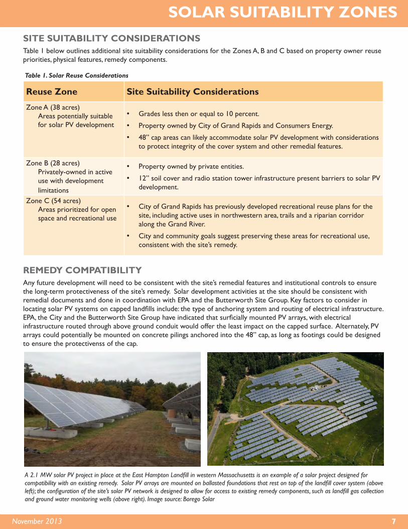
REMEDY COMPATIBILITY Any future development will need to be consistent with the site’s remedial features and institutional controls to ensure the long-term protectiveness of the site’s remedy. Solar development activities at the site should be consistent with remedial documents and done in coordination with EPA and the Butterworth Site Group. Key factors to consider in locating solar PV systems on capped landfills include: the type of anchoring system and routing of electrical infrastructure. EPA, the City and the Butterworth Site Group have indicated that surficially mounted PV arrays, with electrical infrastructure routed through above ground conduit would offer the least impact on the capped surface. Alternately, PV arrays could potentially be mounted on concrete pilings anchored into the 48” cap, as long as footings could be designed to ensure the protectivenss of the cap.
A 2.1 MW solar PV project in place at the East Hampton Landfill in western Massachusetts is an example of a solar project designed for compatibility with an existing remedy. Solar PV arrays are mounted on ballasted foundations that rest on top of the landfill cover system (above left); the configuration of the site’s solar PV network is designed to allow for access to existing remedy components, such as landfill gas collection and ground water monitoring wells (above right). Image source: Borego Solar
Table 1. Solar Reuse Considerations
SOLAR SUITABILITY ZONES

8 Butterworth Landfill Site Solar Reuse Assessment
POTENTIAL SOLAR PV GENERATION AND COST CONSIDERATIONSBased on property owner reuse priorities, remedial considerations and physical features, approximately 38 acres at the site are potentially suitable for solar PV. Reuse Zones A-1 (Eastern Landfill Unit) and A-2 (Western Landfill Unit) highlighted in orange on Figure 5 are likely well-suited for solar PV development. A range of potential solar PV system size, generation and cost estimates corresponding to these zones are listed in Table 2 below. Costs in the solar industry are changing rapidly. While data in Table 1 are from recent published sources, the proposed system cost could end up being considerably less than calculated in this report as costs continue to decline. The estimated installed costs do not factor in potential incentives or solar PV system ownership and financing options but are intended to provide a baseline overview of the upfront capital costs associated with designing and building various sized systems that may be feasible at the site.
Reuse Zone Available Acreage
Estimated Project Size
Estimated Output Installed Costs Annual O&M
Costs
Zone A1 18 3.5 – 5 MW 3700 – 5400 MWh $11.5M – $16.5M $70 k – 100k
Zone A2 20 4 – 5.5 MW 4300 – 5900 MWh $13.2M – $18M $80 k – 110k
AssumptionsSystem Costs:$3.30 - $4.00/Watt installedO&M Costs: $20/kW/Year Area needed: 3.5 - 5 acres / MWMWh=1000 kilowatthours (kWh)Output estimates based on average crystalline silicon PV systemCosts are installed costs and do not include any potential incentives/rebates
SYSTEM SIZE AND COST CONSIDERATIONS
Table 2. Potential Solar PV System Size and Cost Estimates
Estimated costs referenced in Table 2 include design, installation and maintenance costs for the typical solar PV system components illustrated in the diagram above. Image source: National Renewable Energy Lab

9November 2013
RENEWABLE ENERGY INCENTIVES
INCENTIVES AND FINANCING OPPORTUNITIESIdentifying and leveraging applicable incentives and grants is an important part of making PV systems cost effective. Incentives are available at the state and federal level and include both policy-based incentives (e.g., renewable portfolio standards) and financial incentives (e.g., tax credits and rebates). A number of policies and incentives, such as those outlined below, could help facilitate the development of larger scale solar energy projects.
Business Energy Investment Tax Credit • Credit equal to 30% of RE system expenditures, with no maximum credit.• Credits available for eligible systems placed in service on or before December 31, 2016.• Entities with no income tax liability (e.g., municipalities) cannot directly access this incentive if they own RE systems.
Modified Accelerated Cost-Recovery • Current depreciation method for most property.• Qualifying solar energy equipment is eligible for a cost recovery period of five years.
Renewable Portfolio Standard• Utilities must generate 10% of retail electricity sales by 2015 from renewables.• Consumers Energy must produce 200 MW by 2013 and 500 MW by 2015.• Up to 50% of the standard may be met with RECs produced by utility-owned facilities.
Net Metering• RE system must be sized to “meet annual electricity needs.”• Three categories:
• 20 kilowatts (kW) and less - Category 1• 20-150 kW - Category 2• 150-550 kW - Category 3 (only methane digesters over 150 kW)
Experimental Advanced Renewable Program• Performance-based Incentive
•Buy-back tariff program for electricity produced by solar PV systems• Consumers Energy will purchase all electricity produced by a system through a fixed-rate contract of up to 15 years.• Program capped at 3MW (1.5MW for non residential)
•Non-residential system sizes can not exceed 150kW• Most recent non-residential buyback price was $0.19/kWh
The financial viability of a renewable energy project at the Butterworth Landfill site will depend on the ability of the project to take advantage of as many of these funding opportunities as possible either directly as a project owner/developer or through partnerships or other financial arrangements reached with potential solar energy developers who are eligible for the incentives listed above.
At the Aerojet General Corp. Superfund Site in Sacremento County, California, a 6 MW solar project installed on 40 acres supplies 20 percent of the electricity needed for the site’s ground water remediation. This project was financed through a public-private partnership between Aerojet Solar Power, Inc. and the Sacramento Municipal Utility District.

10 Butterworth Landfill Site Solar Reuse Assessment
OWNERSHIP AND PROJECT DEVELOPMENT OPTIONS
In addition to capital costs and available incentives, the type of solar PV project and arrangement between the land owner or host, project developer, investor and utility can have a significant impact on the financial viability of a project. Table 3 below outlines the benefits and limitations of three ownership options identified by the City of Grand Rapids as the most desirable scenarios for the city to host a solar project at the site. A summary of preliminary financial considerations for these three ownership scenarios is included on page 11.
Scenario Overview Benefits LimitationsDirect
OwnershipA public entity owns a PV system.
Under this approach, a public entity (e.g., a municipality) serves as the developer, financier, builder and owner of a PV system. While the public entity may hire subcontractors to build or operate the system, it remains responsible for oversight and financing.
Project financing can take the form of a general obligation bond, a stand-alone bond, bank financing, grants, city revenue or a combination of these sources.
• Potential ability to fund project development with public debt (e.g., bond issuance).
• Full control over project design, operation and risk.
• Ability to choose what to do with renewable energy credits (RECs) from a project (i.e., keep or sell them).
• Direct control of site access and any potential security or site risk considerations.
• Large PV projects are capital intensive.
• Public entities cannot directly benefit from the tax-credit based incentives available to private companies.
• Need to have (or hire) expertise to navigate local utility interconnections and power purchase process.
• May need to self-insure a PV system prior to interconnection.
Third-Party Power
Purchase Agreement
(PPA)
A public entity (municipality) hosts and purchases power from a PV system but does not own it.
The “third party” ownership model is a long-term contract that requires a separate, taxable entity (i.e., the investor / owner of the PV system) to finance and sometimes build and operate the system on a site owned by the host.
The system owner is often a third-party investor who provides investment capital for the project in return for tax benefits.
Typically, the developer will sell electricity to the site host or the local utility via a long-term contract (a PPA).
• No/low up-front cost to public entity.
• Public entity can avoid dealing with complex system design and permitting processes.
• No PV system operation and maintenance responsibilities or costs.
• Public entity can benefit by either receiving competitively priced electricity via a PPA or land lease revenues for making the site available to the solar developer via a lease payment:
• Predetermined and predictable cost of electricity with a PPA.
• PPA negotiation can be lengthy and costly.
• Legal expertise and contracting experience needed to ensure municipality’s interests are well represented.
• Ongoing site access required for system operation and maintenance.
• Typically, project developer or investor owns the RECs.
• Some PPAs require host to purchase the system at end of contract if PPA term is less than the useful life of the system.
OWNERSHIP SCENARIOS
Table 3. PV Project Ownership Scenarios

11November 2013
OWNERSHIP SCENARIOS
Scenario Overview Benefits LimitationsOwnership
FlipA variation of the third party ownership model, where ownership of the PV system would “flip” to the developer (or a public entity) after the investor has fully monetized the tax benefits of a project (typically five or six years, but can be longer).
This type of flip arrangement is typically negotiated up front and the terms of a flip included in a PPA. The public entity (host) would have the option to buy out all or most of the owner’s interest in a project at the fair market value of the PV system.
If an ownership transfer model is desirable, it should be considered during the Request for Information (RFI) development phase.
• Similar benefits to third party PPA in terms of pre-flip benefits.
• A public entity could have the option to purchase the system and take full ownership after RECs and depreciation are realized by the investor.
• Potential opportunity, upon owning the system, for the public entity to continue to sell electricity and/or RECs to a utility or replace electricity purchased from the grid.
• Similar limitations to third party PPA in terms of pre-flip challenges.
• Model often implemented as a partnership-flip, where developer and lender create a partnership in the form of a special purpose entity (SPE) and then share pre-negotiated percentages of the income, incentives and depreciation of the system.
KEY OWNERSHIP AND FINANCIAL CONSIDERATIONS A preliminary financial analysis examined the potential impact of a 5MW solar facility located at the site. This size project could be located in Zone A1 or A2, shown in Figure 6, and help the City meet its goals of reducing municipal energy use. Potential impacts under three different project development scenarios are summarized below.
Direct Ownership
A government owned and financed system would carry some level of financial risk. Large solar projects are capital intensive and the City cannot directly benefit from the tax-credit based incentives available to private companies. The City may also need to retain expertise to navigate the local utility interconnection and power purchase process. A City-owned solar project funded with public debt could offset a portion of the electricity usage from the City’s waste water treatment plant and result in energy cost savings if the installed cost of a solar project drops below $2.50/W or the anticipated price of electricity from the grid increases at an annual rate of 9 percent.
Third-Party Power Purchase Agreement (PPA)
A third- party PPA may provide the most viable way for a system to be financed and installed at the site. A purchase agreement approach can provide cost certainty against long-term electricity prices and will generally be economically viable if a project can be developed with a PPA price that is competitive with utility electricity rates (current rates or projected rate increases). This arrangement could potentially allow the City to utilize the benefits of the tax credits that are available to a third-party developer while not directly receiving them.
Ownership Flip
The ownership flip approach, a variation on the Third-Party PPA, could enable the City to acquire a solar project at a discount at a specified point in the future. The viability of an ownership flip approach will depend on the final negotiated “fair market value” of a system and whether the public entity will continue to be able to sell output from the system once it assumes ownership.
Table 3. PV Project Ownership Scenarios (continued)

12 Butterworth Landfill Site Solar Reuse Assessment
RESOURCESRegion 5 Superfund Redevelopment http://www.epa.gov/region5/superfund/redevelop
Superfund Redevelopment Initiative http://www.epa.gov/superfund/programs/recycle
Re-Powering America Best Practices for Siting Solar Photovoltaics on Municipal Solid Waste Landfillshttp://www.epa.gov/renewableenergyland/docs/best_practices_siting_solar_photovoltaic_final.pdf
Re-Powering America Renewable Energy Interactive Mapping Toolhttp://epa.gov/renewableenergyland/mapping_tool.htm
Siting Clean and Renewable Energy on Contaminated Lands and Mining Sites U.S. Environmental Protection Agency. Office of Solid Waste and Emergency Response. September 2008.
Solar Energy Industries Associationhttp://www.seia.org
Database of State Incentives for Renewables & Efficiency (DSIRE) http://www.dsireusa.org
DOE Solar Energy Technologies Programhttp://www1.eere.energy.gov/solar
NREL Photovoltaic (PV) Pricing Trends: Historical, Recent, and Near-Term Projections http://www.nrel.gov/docs/fy13osti/56776.pdf
NREL Renewable Energy Resource Mapshttp://www.nrel.gov/renewable_resources
NREL Solar Advisor Modelhttps://www.nrel.gov/analysis/sam
ACKNOWLEDGMENTSThe following organizations and entities contributed to the findings of the Butterworth Solar Reuse Assessment:
• City of Grand Rapids• Butterworth Site Group• Consumers Energy• EPA Region 5 Reuse assessment developed by Skeo Solutions
SOLAR REUSE CONSIDERATIONS
Solar Reuse SuitabilityThe reuse assessment has identified 38 acres suitable for direct-use and utility-scale solar PV development. With suitable acreage divided among two landfill units, the site offers the flexibility to accommodate system sizes ranging from 5 MW to 10 MW.
Multi-use ApproachThe site can accommodate multiple uses to help achieve the City’s recreation and sustainable energy goals. Focusing solar PV development on the most suitable areas would allow the City to reserve approximately 54 acres in northwestern and southern portions of the site for open space and programmed recreational uses.
Remedy CompatibilitySolar PV development is likely compatible with the existing remedial features. PV arrays would need to be configured around remedy features. PV array installation using a ballasted anchoring system could ensure minimal disturbance of the cap surface. As institutional controls are finalized, EPA may want to ensure that use restrictions do not preclude solar reuse.
PhasingSolar PV arrays could be installed in phases at the site. 18 acres at the Eastern Landfill Unit can accommodate a 5 MW solar project. Located in close proximity to Consumers Energy’s existing substation, this area is likely well-suited for an initial phase of solar development. 20 acres at the Western Landfill Unit could support an additional 5 MW project in a later phase. A phased approach would offer the opportunity to test financial feasibility at a small scale.
Ownership and Development OptionsThe City and Consumers Energy have initiated discussions to identify solar project ownership, development and financing options. The City is considering a range of potential ownership options for a solar project including: 1) Direct Ownership, 2) Third-party PPA and 3) Ownership Flip. Working with a solar renewable energy developer to locate a solar PV project at the site through a Third-party PPA ownership model would likely provide the most efficient and cost effective approach for the City to host a renewable energy project at the site.
SUMMARY
Sponsored by the EPA Region 5 Superfund Redevelopment Initiative
CONTACT INFORMATIONDion Novak, EPA Region 5, Remedial Project Manager: (312-886-4737 | [email protected]
Tom Bloom, EPA Region 5, Reuse Coordinator: (312) 886-1967 | [email protected]