solid edge solutions for machinery design edge solutions for machinery design machinery makers face...
TRANSCRIPT


Solid Edge solutions for machinery designMachinery makers face some of the most extreme design challenges inthe manufacturing industries:
• How to engineer and build complex machines in a very limitedwindow to meet demanding delivery schedules
• How to provide machinery solutions that best fulfill functionalspecifications but also fit within engineering and budget constraints
• How to innovate beyond competitors while maintaining quality andserviceability
• How to get it right the first time
Solid Edge, the leading mid-range CAD software from UGS,gives machinery makers comprehensive computer-aidedtools tailored for machinery design problems. Withindustrial-strength 3D modeling, assembly design,engineering aids, and 2D drafting, Solid Edge haseverything you need to get down to the business ofmachinery design. These uniquely productive tools areremarkably affordable and easy to use, to help yourealize the business benefits of advanced 3D machinedesign technology:
Faster bid response, quote preparation, and proposal.With Solid Edge's innovative CAD tools, you can quickly develop newdesigns and alternative machine configurations in response to customerspecifications. Solid models clearly communicate your proposedmachinery solutions, and correct Bills of Material from CAD models helpimprove the accuracy of quotes.
Greater design productivity and throughput. With Solid Edge, your design team can get more workdone with less effort. Your designers will readily master advanced 3D CAD solid modeling techniques without a longand expensive learning curve. Streamlined design operations with an intuitive user interface make Solid Edge themost productive CAD system available, requiring fewer commands and mouse clicks to get the job done. The addedproductivity results in significant direct labor and time savings.
Shorter design, manufacturing, and delivery cycles. Solid Edge's productivity edge automates andstreamlines all design functions, from concept layout through detail design and drafting, to significantly reducemachinery development time. With integrated applications for CAE, CAM, PDM and related functions, Solid Edgesupports full-cycle efficiencies that get your machines delivered on time.
Reduced product development costs. With the lowest cost of ownership of any 3D CAD system, SolidEdge gives you an up-front advantage in your outlay for design technology. In addition to direct engineering laborand time savings, Solid Edge also helps reduce costs associated with prototyping, errors and revisions, andengineering change orders.
Fewer errors and design revisions. With Solid Edge, you build accurate virtual machinery modelsthat help you avoid costly errors, scrap, and rework. You can detect and eliminate fit and function problemslong before they reach the shop floor, and reduce errors and changes from customers and suppliers with 3Ddesign communication.
Improved machine quality, function, and reliability. The engineering aids in Solid Edge help youevaluate more design alternatives in less time, so you can optimize machine performance and reliability. Solid Edgeincludes mass properties calculations, design sensors, motion analysis, interference detection, and other built-intools, as well as integrated CAE software applications for detailed finite element, kinematics, and dynamics analysis.

"Solid Edge gives us everythingwe need for machinery design, at a
fraction of the cost of high-end systems."
Paul Choate, engineering manager,
Alcoa Packaging MachineryEnglewood, Colorado
“By building the machinedigitally using the software's
assembly modeling capability, weknew everything would fit. That was
much more efficient than tearing aparta prototype to make it work."
Steve Cook, vice-president,Dayton Systems Group
Dayton, Ohio
"It was clear to us that SolidEdge would provide a higher level
of productivity and return oninvestment than the other systems we
evaluated. We were also very impressedwith Solid Edge's ease-of-use."
J.Y. Yoo, automation R&D manager,Sun Yang Tech,Inchon, Korea
"With Solid Edge, we cangive potential customers an
accurate picture of a machine thatdoes not exist yet, and we can farmore easily take account of their
specific requirements in theend product."
Rob Stikkelorum, deputy managerAPS Engineering,The Netherlands
"For a new cartoning machineline, Solid Edge cut our
development time in half. We saved alot of time and therefore a lot
of money."
Rick Lidington,executive VP of operations,
RA Jones, Covington, Kentucky
"We’re not only designingmachines faster, we’re making
them better."
Alan D. Flores II,mechanical design engineer,
Casa Herrera, Pomona, California
Image courtesy of Giringhelli
By increasing engineering capacity, improving quality, and reducing lead times and costs, SolidEdge is helping machinery makers achieve strategic business objectives of greater market share,revenue, and profitability.
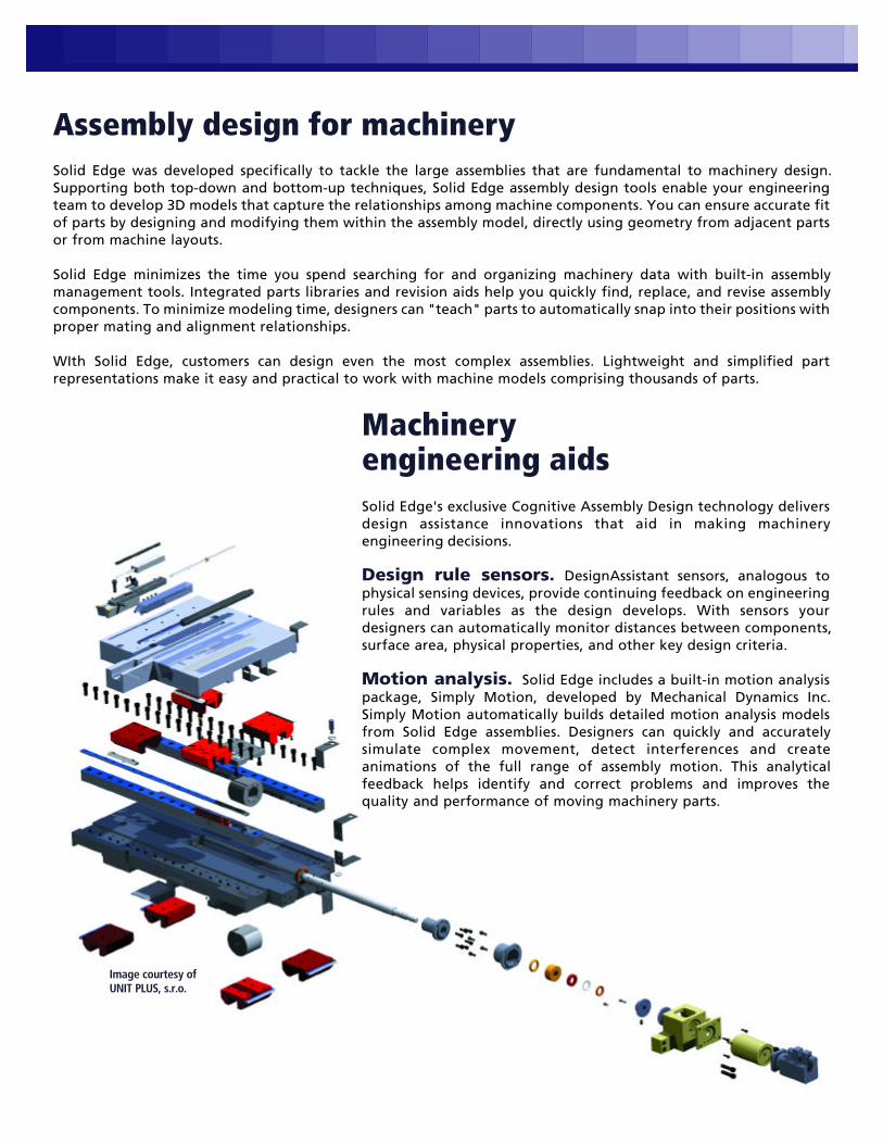
Assembly design for machinerySolid Edge was developed specifically to tackle the large assemblies that are fundamental to machinery design.Supporting both top-down and bottom-up techniques, Solid Edge assembly design tools enable your engineeringteam to develop 3D models that capture the relationships among machine components. You can ensure accurate fitof parts by designing and modifying them within the assembly model, directly using geometry from adjacent partsor from machine layouts.
Solid Edge minimizes the time you spend searching for and organizing machinery data with built-in assemblymanagement tools. Integrated parts libraries and revision aids help you quickly find, replace, and revise assemblycomponents. To minimize modeling time, designers can "teach" parts to automatically snap into their positions withproper mating and alignment relationships.
WIth Solid Edge, customers can design even the most complex assemblies. Lightweight and simplified partrepresentations make it easy and practical to work with machine models comprising thousands of parts.
Machinery engineering aidsSolid Edge's exclusive Cognitive Assembly Design technology deliversdesign assistance innovations that aid in making machineryengineering decisions.
Design rule sensors. DesignAssistant sensors, analogous tophysical sensing devices, provide continuing feedback on engineeringrules and variables as the design develops. With sensors yourdesigners can automatically monitor distances between components,surface area, physical properties, and other key design criteria.
Motion analysis. Solid Edge includes a built-in motion analysispackage, Simply Motion, developed by Mechanical Dynamics Inc.Simply Motion automatically builds detailed motion analysis modelsfrom Solid Edge assemblies. Designers can quickly and accuratelysimulate complex movement, detect interferences and createanimations of the full range of assembly motion. This analyticalfeedback helps identify and correct problems and improves thequality and performance of moving machinery parts.
Image courtesy of UNIT PLUS, s.r.o.

On-line machinery reference. TheEngineering Handbook is an integrated add-onpackage for Solid Edge that provides on-linereference and automatic parts creation formachinery designers. Developed byMechSoft.com, Inc., the Engineering Handbookincludes calculations representing standardmathematical formulas and physical theoriesfor a broad range of machinery components. Acalculation-driven parts generator automat-ically creates correct-by-construction partmodels from the engineering calculations,based on desired load and service criteria. Alsoincluded is a complete on-line machineryreference that documents algorithms, formulasand theories.
Third-party engineering software.Solid Edge works with the leading softwareapplications for detailed engineering analysis,simulation, and optimization. Finite elementanalysis, kinematic and dynamic simulation,and other engineering software aids integratewith Solid Edge to accelerate analysis cycles.
Greater design productivity for machinery componentsSolid Edge helps machinery engineers design more rapidly with parametric, feature-based modeling tools thatefficiently build machine parts. Beginning with base parts created from a revolved or extruded sketch, designers caneasily add typical mechanical features including holes, cutouts, protrusions, rounds, and thin-wall features, as wellas more complex geometric features like draft angles, sweeps, lofts, helical features and feature patterns. Partgeometry, relationships, and dimensions can be changed quickly to investigate design alternatives.
Solid Edge boosts design productivity with specialized, process-specific environments for machine componentsincluding sheet metal, weldments, and tubing. These environments provide tailored commands and structuredworkflows that help you design these components much more quickly than with general-purpose CADmodeling tools.
Sheet metal. Solid Edge's sheet metal environment uses standard sheet metal and fabrication terminology, withstreamlined modeling commands for tabs, flanges, louvers, dimples, cutouts, mitred corners, corner breaks, andother sheet metal-specific part features. With automated placement of bend relief, bend allowance calculations,and flat pattern development, Solid Edge delivers the most advanced sheet metal CAD package available.
Weldments. A customized command set in Solid Edge accelerates design of machinery weldments. Theweldment environment assists in defining the constituent parts of weldments, as well as weld beads, pre-weldsurface treatments, and machining operations after the welds are applied. Solid Edge drafting documents the entireweldment manufacturing process, with component drawings as well as pre-weld and post-machining views.Weldment designs can be placed and manipulated as single components in machinery models.
Tubing. Solid Edge XpresRoute is an integrated add-on package that rapidly routes and models tubing forhydraulic or pneumatic systems. The XpresRoute module helps you quickly define the 3D tube properties and pathsbetween other assembly components. After defining these parameters, XpresRoute automatically creates a 3D solidmodel of the tube part, complete with end treatments. Tubing parts are dynamically associative to the componentsthey connect, so that they automatically adjust when changes are made in related parts.
Image courtesy of Gem City Engineering

Streamlined draftingSolid Edge improves the quality and accuracy ofengineering documentation with a powerful system forcreating 2D drawings. Whether you are working froma solid part, an assembly model, or a blank drawingsheet, Solid Edge drafting and detailing tools completeyour drawings more rapidly and easily than any otherCAD system.
Developed specifically for mechanical drawingproduction, Solid Edge provides excellent drawinglayout, detailing, annotation, and dimensioningcontrols that automatically comply with the mechanicaldrafting standard you select.
Solid Edge's associative drafting system automatically creates and updates drawings from 3D models. Designerssimply select the model and then select and arrange views on the sheet to create the drawing graphics. Solid Edgequickly creates standard and auxiliary views, including section, detail, and isometric views. As changes are made tomachinery models, associated drawings update automatically to reflect the changes. The drafting system in SolidEdge dramatically accelerates assembly drawing by automatically creating exploded views, balloons, parts lists, andBills of Material.
Practical designcollaborationWith Solid Edge, machinery manufacturers can improvedesign data sharing and collaboration with practical,inexpensive tools. SmartView is a free viewer for Solid Edgedesign files that works independently of the CAD software,enabling anyone in the enterprise or supply chain to viewdrawings or part and assembly models. To leverage companyintranets, extranets or the Internet for design commu-nication, Solid Edge Web Publisher provides a fast and easymethod for publishing web pages with Solid Edge 3D models,Bills of Material, and related data. This integrated moduleworks directly from the Solid Edge design session using asimple wizard interface that requires no web publishingexpertise. Published models can be viewed on the web withthe Microsoft Internet Explorer browser, and users canmanipulate the display of the model and even manuallycreate exploded assembly views. Web Publisher is aninexpensive solution for creating web-ready spare partscatalogs or engineer-to-order applications for customers.
For real-time collaborative design, Solid Edge uses industry-standard visualization and collaboration technologiesdeveloped by Engineering Animation Inc. These products andservices include Solid Edge Exchange, a hosted site wheredesign teams, customers, and suppliers can establishcollaborative projects, organize, share, and manage data, andconcurrently access, review, and mark up design models.
Image courtesy of Production Technology Oras Ltd.
Easing the move to 3DThe majority of machinery makers are still using design processes based on 2D engineering drawings, even if theyacknowledge the business and productivity benefits of 3D design. Solid Edge removes the roadblocks on the pathto 3D by making the migration significantly less expensive and less difficult.
Solid Edge delivers advanced 3D CAD in the industry's most intuitive Windows-based interface, so it is remarkablyeasy to learn and use. Patented STREAM technology employs inference logic and decision management techniquesto streamline operation and shorten the learning curve.
Dozens of built-in tutorials provide self-paced, step-by-step instruction and guidance as designers use the software.The on-line help system includes information for users moving from 2D CAD systems. With these tools, thousands offormer 2D designers have become productive with Solid Edge within hours of installing the software.
With Solid Edge, machinery designers who are moving from 2D need not abandon their legacy data or CADknowledge. Solid Edge builds upon 2D design practices, and directly uses 2D CAD data in 3D modeling operations.Built-in translators provide simple, wizard-driven import and export of 2D designs in AutoCAD format.
Data exchangeMachinery design teams can readily exchange CAD data with other systems using Solid Edge's built in datatranslation tools. These support two-way conversion of widely used CAD formats, including AutoCAD (DXF/DWG)and Pro/ENGINEER, the IGES and STEP neutral formats, and the Parasolid format used by a host of CAD, CAM, andCAE software programs. An additional Feature Recognizer module is available to add parametric design intelligenceto imported models.
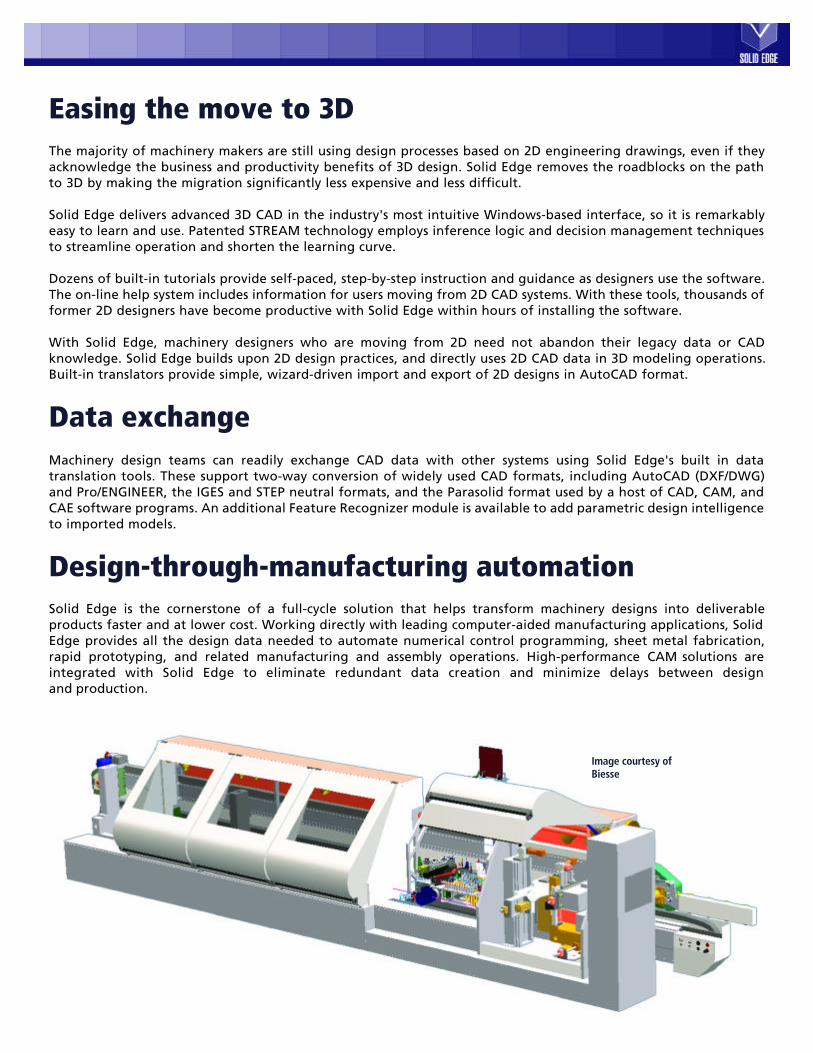
Design-through-manufacturing automationSolid Edge is the cornerstone of a full-cycle solution that helps transform machinery designs into deliverableproducts faster and at lower cost. Working directly with leading computer-aided manufacturing applications, SolidEdge provides all the design data needed to automate numerical control programming, sheet metal fabrication,rapid prototyping, and related manufacturing and assembly operations. High-performance CAM solutions areintegrated with Solid Edge to eliminate redundant data creation and minimize delays between designand production.
Image courtesy of Biesse
Solid Edge: the provensolution for machinery designSolid Edge is uniquely positioned to deliver exceptionalvalue to machinery designers. Developed from its outsetto address productivity issues in machinery develop-ment, Solid Edge directly addresses the practical aspectsof machinery design engineering with powerful CADfunctions that are exceptionally easy to learn and use.Leading machinery manufacturers worldwide recognizethat Solid Edge delivers more productive tools with alower cost of ownership, which yields a superior returnon their CAD investment. Our customers in themachinery industry rely on Solid Edge as a strategic toolto help them realize the benefits of better quality, lowercosts, and shorter delivery cycles.
Cover image courtesy of Bruckner Maschinenbau GmbH. Back cover image courtesy of Kaeser Kompressoren GmbH. UGS and Solid Edge are trademarks, registered trademarks or service marks of UGS. All othertrademarks, registered trademarks or service marks belong to their respective holders. The information within is subject to change without notice and does not represent a commitment on the part of UGS.
UGS InternationalHeadquarters
Americas10824 Hope StreetCypress, CA 90630USA(800) 498-5351
EuropeCentrum House101-103 Fleet RoadGU13 8NZUK+31 (0) 79363 5515
Asia PacificSuite 1701Cheung Kong Center2 Queen’s Road CentralHONG KONG(852) 2230-3333
For more information, callyour Solid Edge Reseller:
SE-MACH-BROCH