solid works - tips&good practices - part 2
TRANSCRIPT

8/9/2019 Solid Works - Tips&Good Practices - part 2
http://slidepdf.com/reader/full/solid-works-tipsgood-practices-part-2 1/13
SOLIDWORKS TIPS / GOOD PRACTICE
Part ± 2
I.Karthik (30-04-2010)

8/9/2019 Solid Works - Tips&Good Practices - part 2
http://slidepdf.com/reader/full/solid-works-tipsgood-practices-part-2 2/13
Identification : Feature Naming
Automatically promptsthe user to give a name
for that feature 2

8/9/2019 Solid Works - Tips&Good Practices - part 2
http://slidepdf.com/reader/full/solid-works-tipsgood-practices-part-2 3/13
2D vs. 3D : Fillets / Chamfers
Here the fillet is
sketched and then
the part is extruded.
Features can be better managed
and controlled
S ame logic applies for ³chamfer´ also
3

8/9/2019 Solid Works - Tips&Good Practices - part 2
http://slidepdf.com/reader/full/solid-works-tipsgood-practices-part-2 4/13
Merge result: ?
Extrude 2 merged with Extrude 1
Sketch for cut extrude 3
When ³Up to body´ is selected to define the cut
direction of Extrude 3, it selects the top surface of
the extrude 2 - because Ext-1 & Ext-2 are merged
Top surface of the extrude 2
C ontinued in the next page
Section view
of the final cut
4

8/9/2019 Solid Works - Tips&Good Practices - part 2
http://slidepdf.com/reader/full/solid-works-tipsgood-practices-part-2 5/13
Merge result: ? Sketch for cut extrude 3
When ³Up to body´ is selected to define the cut
direction of Extrude 3, it selects the top surface of the
extrude 1 - because Ext-1 & Ext-2 are not merged (Here
Extrude 1 & Extrude 2 are treated as separate bodies ,
so the cut operation stop¶s at the boundary between
Body 1 : Extrude 1 & Body 1 : Extrude 2 )
Top surface of the extrude 1Extrude 2 not merged with Extrude 1
Section view
of the final cut
5

8/9/2019 Solid Works - Tips&Good Practices - part 2
http://slidepdf.com/reader/full/solid-works-tipsgood-practices-part-2 6/13
Assembly: Search parts
3. Type in the part number
that you need to search and
click enter
1.Right click on the Assembly file name in the left pane
2.Click ³Go to´
C ontinued in the next page
6

8/9/2019 Solid Works - Tips&Good Practices - part 2
http://slidepdf.com/reader/full/solid-works-tipsgood-practices-part-2 7/13

8/9/2019 Solid Works - Tips&Good Practices - part 2
http://slidepdf.com/reader/full/solid-works-tipsgood-practices-part-2 8/13
Sheet metal: Break corner Vs Chamfer Vs Sketched Chamfer
1. You have to manually dimension the chamfers to get it in the right format
2. By doing so, the chamfer dimension will not be parametric
3. ³Break corner´ cannot be used for internal edges. you need to use default
³chamfer´ option for that.
4. SOLIDWORKS does not have dual dimension option for chamfers
After inserting the modelitems in the drawing, note
that the chamfer dimensionsare not in the
format as intended
Chamfer dimensions
manually inserted.These are in the rightformat
8

8/9/2019 Solid Works - Tips&Good Practices - part 2
http://slidepdf.com/reader/full/solid-works-tipsgood-practices-part-2 9/13
Sketch : Slot ± Arc dimension from radius to diameter
Arc : radius dimension
Display as diameter
Right click on
the dimension
Arc : Diameter dimension
9

8/9/2019 Solid Works - Tips&Good Practices - part 2
http://slidepdf.com/reader/full/solid-works-tipsgood-practices-part-2 10/13
3D : Shell Vs. Multi profile construction
Hollow tube
Here, multiple profiles (in a sketch)were used to create a hollow tube ina single instance
It¶s hard to control or modify due tomultiple profiles and relateddimensions
Here, single profile per sketch isused to create a tube. Finally shell isused to convert the solid tube in toa hollow one.
Though it adds another feature(shell) to the list, it's simple inconstruction and hence easy tomodify.
10
8/9/2019 Solid Works - Tips&Good Practices - part 2
http://slidepdf.com/reader/full/solid-works-tipsgood-practices-part-2 11/13
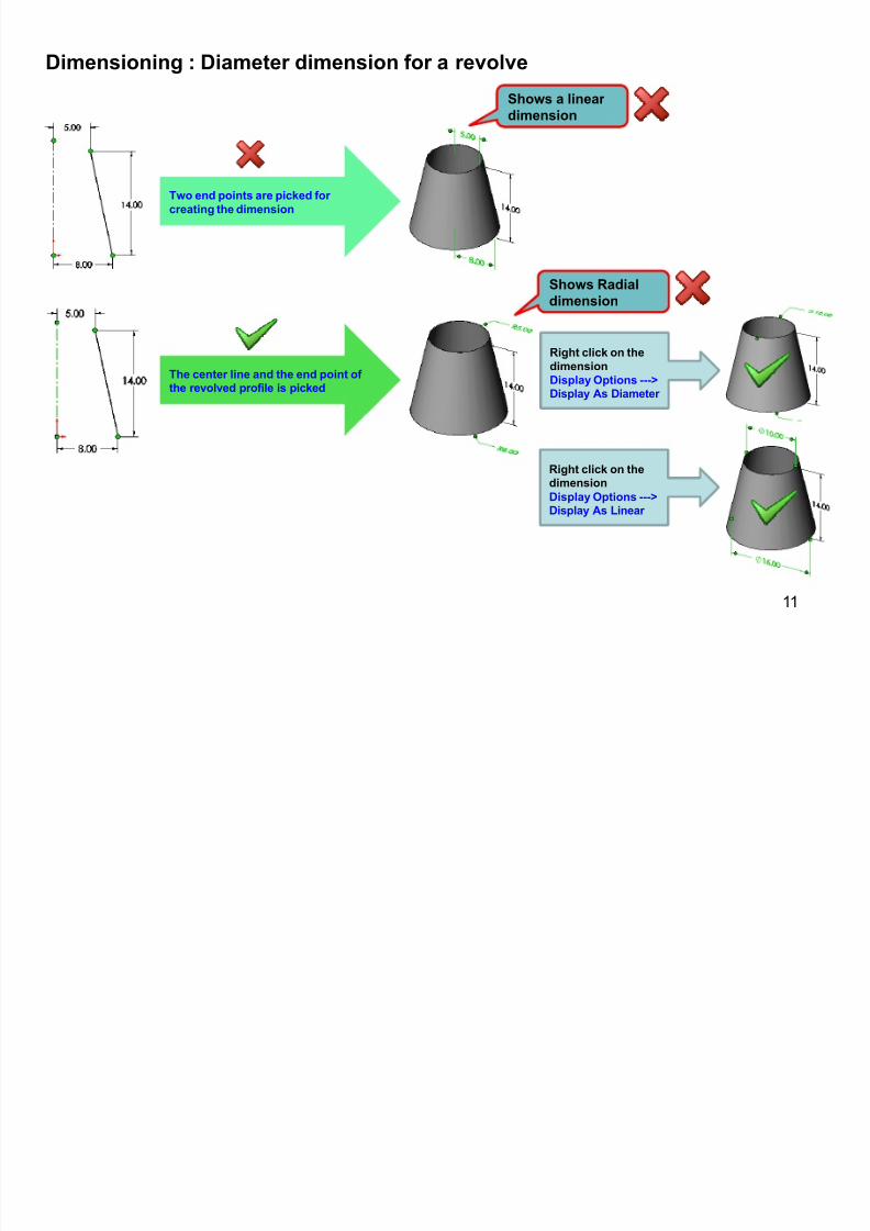
Dimensioning : Diameter dimension for a revolve
11
Shows Radial
dimension
The center line and the end point of the revolved profile is picked
Two end points are picked for
creating the dimension
Shows a linear
dimension
Right click on the
dimension
Display Options --->Display As Diameter
Right click on thedimension
Display Options --->Display As Linear

8/9/2019 Solid Works - Tips&Good Practices - part 2
http://slidepdf.com/reader/full/solid-works-tipsgood-practices-part-2 12/13
12
Drawing : Detached drawing
³Detached drawing´
S ee SOLIDWORKS help for a detailed explanation about the logics involved in using a ³detached drawing´
To create a detached drawing:
1. Open an existing dwg for which you need to
create a detached dwg
2. File -- save as (Detached dwg)
Save it and its ready to be mailed / moved
alone with out its part
8/9/2019 Solid Works - Tips&Good Practices - part 2
http://slidepdf.com/reader/full/solid-works-tipsgood-practices-part-2 13/13
13
1. http://help.solidworks.com/
2. http://www.caddigest.com/subjects/SolidWorks/tutorials.htm
3. http://www.theswgeek.com/
4. http://www.solidworkstips.com/content/
5. http://www.aboutsolidworks.com/
6. http://www.sheetmetalguy.com/solidworks/tips.htm
7. http://www.capinc.com/pages/support/downloads.cfm
8. http://www.solidsmack.com/
9. http://sw.fcsuper.com/index.php
10. http://www.solidworker.com/
11. http://www.mikejwilson.com/solidworks/solidworks_files.htm
12. YOUTUBE : It has got much more than what we usually see ,Yes it has excellent SOLIDWORKS stuff.
Find any mistakes
Got some more exciting tips
Wish to improve this database
Pls update and
communicate
If
U