some results about yarn winding in ring spinning · the low spinning efficiency is due to the...
TRANSCRIPT
This is the published version Tang, Zheng-Xue, Wang, Xungai and Fraser, Barrie 2006, Recent studies on yarn tension and energy consumption in ring spinning, Research journal of textile and apparel, vol. 9, no. 4, pp. 1-15. Available from Deakin Research Online http://hdl.handle.net/10536/DRO/DU:30003922 Every reasonable effort has been made to ensure that permission has been obtained for items included in Deakin Research Online. If you believe that your rights have been infringed by this repository, please contact [email protected] Copyright: 2006, Research journal of textile and apparel
1
RECENT STUDIES ON YARN TENSION AND ENERGY CONSUMPTION
IN RING SPINNING1
Zhengxue Tang, Xungai Wang and W. Barrie Fraser*
School of Engineering and Technology, Deakin University, VIC 3217 Australia * School of Mathematics and Statistics, The University of Sydney, NSW 2006, Australia
ABSTRACT
High energy consumption remains a key challenge for the widely used ring spinning
system. Tackling this challenge requires a full understanding of the various factors that
contribute to yarn tension and energy consumption during ring spinning. In this paper,
we report our recent experimental and theoretical research on air drag, yarn tension and
energy consumption in ring spinning. A specially constructed rig was used to simulate
the ring spinning process; and yarn tension at the guide-eye was measured for different
yarns under different conditions. The effect of yarn hairiness on the air drag acting on a
rotating yarn package and on a ballooning yarn was examined. Models of the power
requirements for overcoming the air drag, increasing the kinetic energy of the yarn
package (bobbin and wound yarn) and overcoming the yarn wind-on tension were
developed. The ratio of energy-consumption to yarn-production over a full yarn package
was discussed. A program to simulate yarn winding in ring spinning was implemented,
which can generate the balloon shape and predict yarn tension under a given spinning
condition. The simulation results were verified with experimental results obtained from
spinning cotton and wool yarns.
Key words: Ring spinning; yarn tension; energy consumption; yarn balloon; air
drag; modelling
1. INTRODUCTION
The two outstanding challenges for ring spinning are high power consumption and low
productivity. The low spinning efficiency is due to the relatively high yarn tension
during ring spinning, which increases the chance of yarn breakage. The high power
consumption is caused by high air drag from the ballooning yarn (Fraser, 1993a) and
yarn hairiness (Chang, et al., 2003), which also generates high yarn tension during ring
spinning.
According to the theory of fluid mechanics (John and Haberman, 1988), the air drag on
a body is due to the sum of pressure drag and skin friction drag. In many cases, one or
the other of these two drags is predominant. In ring spinning, air drag on the rotating
yarn package is mainly due to skin friction drag on the package surface, while pressure
drag is the dominant one on the ballooning yarn. Understanding the various factors that
contribute to air drag is important in the optimization of the ring spinning process.
1 Based on a paper presented at the 84th World Conference of the Textile Institute, Raleigh, March 2005
2
In this paper, we will report our recent experimental and theoretical research into air
drag, yarn tension and energy consumption in ring spinning.
2. EXPERIMENTAL
2.1 Yarn Samples and Their Hairiness Indexes
We used various singed and un-singed cotton and wool yarns in the experiments. We
measured the hairiness index of un-singed yarns on an Uster Tester 4 under standard
conditions and at a speed of 400 m/min. Table I lists the hairiness results, which we will
use for further analyses in the following sections.
Table I. Hairiness index of cotton and wool yarns (Tang, et al., 2004e, 2005a)
Yarn type Cotton Cotton Wool Wool
Yarn count (tex) 38.0 50.4 70.1 103.0
Hairiness index (H) 8.1 8.1 12.0 13.0
We used a yarn and the roving build method to wind a yarn package with one layer and
removed the hairiness on the package surface by singeing. Then we obtained the singed
yarn by unwinding the yarn from the package.
2.2 Power Consumption for Rotating Yarn Packages
We used a single spindle experimental rig (see Figure 3 in Chang, et al. (2003)) to
measure the level of power consumption during the rotation of a single yarn package.
We used the cotton or wool yarn of a given count and the roving build method to wind
different yarn packages with the appropriate number of layers, which was determined
by the requested package diameter and yarn count. We removed the hairiness on the
surface of some packages via singeing. For each of the packages, we took the diameter
measurements at two ends and in the middle, and used their average as the diameter of
the package. All packages had the same height h0 of 0.245 m. We tested each of the
packages twice at spindle speeds ranging from 2,000 rpm (i.e. 33 rps) to 16,000 rpm (i.e.
267 rps), in steps of 2000 rpm. For each of the packages at different spindle speeds, we
took the average values of the current and voltage readings from the test device and
used these readings to calculate the power consumption at a given spindle speed (Tang,
et al., 2004b, 2005a).
2.3 Tension in a Ballooning Yarn
We measured tension in the singed and un-singed yarns using a specially constructed rig
(see Figure 2 in Tang, et al. (2004e)), which can rotate a yarn at high speeds without
inserting any real twist into the yarn.
The end of the yarn which passes through a guide-eye was attached to the tension sensor
and another end was fixed on a rotating eyelet. When the eyelet starts rotating, the yarn
between the guide-eye and eyelet formed a balloon and generated tension in the yarn.
3
The tension signal at the guide-eye was digitized by the computer data acquisition
system.
For yarn tension measurement, we „spun‟ the yarns at different „twisting‟ speeds on the
rig, with the balloon height varying from 120 mm to 360 mm. We measured the yarn
rotating speed (i.e. spindle speed) with a digital tachometer during the tests, and used a
digital camera with video capability to capture the balloon shape.
3. THEORETICAL
3.1 A Geometrical Model of a Bobbin with Full Yarn Package
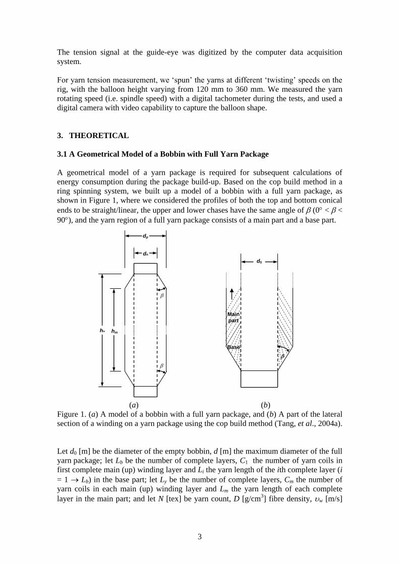
A geometrical model of a yarn package is required for subsequent calculations of
energy consumption during the package build-up. Based on the cop build method in a
ring spinning system, we built up a model of a bobbin with a full yarn package, as
shown in Figure 1, where we considered the profiles of both the top and bottom conical
ends to be straight/linear, the upper and lower chases have the same angle of (0 < <
90), and the yarn region of a full yarn package consists of a main part and a base part.
(a) (b)
Figure 1. (a) A model of a bobbin with a full yarn package, and (b) A part of the lateral
section of a winding on a yarn package using the cop build method (Tang, et al., 2004a).
Let d0 [m] be the diameter of the empty bobbin, d [m] the maximum diameter of the full
yarn package; let Lb be the number of complete layers, C1 the number of yarn coils in
first complete main (up) winding layer and Li the yarn length of the ith complete layer (i
= 1 Lb) in the base part; let Ly be the number of complete layers, Cm the number of
yarn coils in each main (up) winding layer and Lm the yarn length of each complete
layer in the main part; and let N [tex] be yarn count, D [g/cm3] fibre density, w [m/s]
Main
part
Base
d0
d0
dp
h0 hm
4
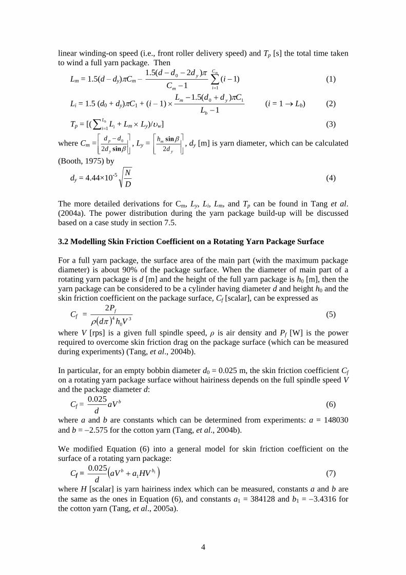
linear winding-on speed (i.e., front roller delivery speed) and Tp [s] the total time taken
to wind a full yarn package. Then
Lm = 1.5(d – dy)Cm – 1
)2(5.1 0
m
y
C
ddd
mC
i
i1
)1( (1)
Li = 1.5 (d0 + dy)C1 + (i – 1) 1
)(5.1 10
b
ym
L
CddL (i = 1 Lb) (2)
Tp = [(
bL
i iL1
+ Lm Ly)/w] (3)
where Cm =
siny
p
d
dd
2
0 , Ly =
y
m
d
h
2
sin, dy [m] is yarn diameter, which can be calculated
(Booth, 1975) by
dy = 4.44×10⁻⁵
D
N (4)
The more detailed derivations for Cm, Ly, Li, Lm, and Tp can be found in Tang et al.
(2004a). The power distribution during the yarn package build-up will be discussed
based on a case study in section 7.5.
3.2 Modelling Skin Friction Coefficient on a Rotating Yarn Package Surface
For a full yarn package, the surface area of the main part (with the maximum package
diameter) is about 90% of the package surface. When the diameter of main part of a
rotating yarn package is d [m] and the height of the full yarn package is h0 [m], then the
yarn package can be considered to be a cylinder having diameter d and height h0 and the
skin friction coefficient on the package surface, Cf [scalar], can be expressed as
Cf = 3
0
4
2
Vhd
Pf
(5)
where V [rps] is a given full spindle speed, ρ is air density and Pf [W] is the power
required to overcome skin friction drag on the package surface (which can be measured
during experiments) (Tang, et al., 2004b).
In particular, for an empty bobbin diameter d0 = 0.025 m, the skin friction coefficient Cf
on a rotating yarn package surface without hairiness depends on the full spindle speed V
and the package diameter d:
Cf = baVd
025.0 (6)
where a and b are constants which can be determined from experiments: a = 148030
and b = 2.575 for the cotton yarn (Tang, et al., 2004b).
We modified Equation (6) into a general model for skin friction coefficient on the
surface of a rotating yarn package:
Cf = 1
1
025.0 bb HVaaVd
(7)
where H [scalar] is yarn hairiness index which can be measured, constants a and b are
the same as the ones in Equation (6), and constants a1 = 384128 and b1 = 3.4316 for
the cotton yarn (Tang, et al., 2005a).
5
Furthermore, a new model which can more accurately predict the skin friction
coefficient on the surface of a rotating wool yarn package has been developed and is
shown below:
Cf = 1
14.1025.0 bb HVaaVd
(7a)
where constants a, b, a1 and b1 are the same as ones in Equation (7), respectively.
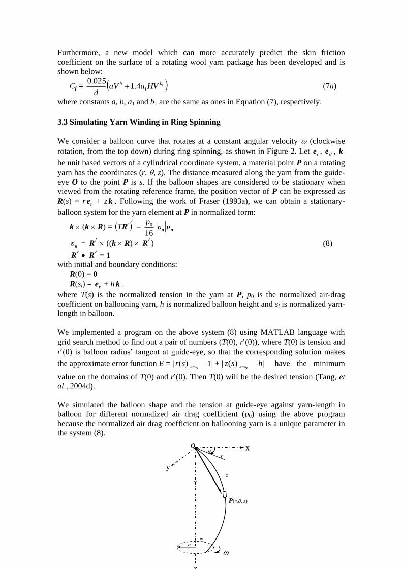
3.3 Simulating Yarn Winding in Ring Spinning
We consider a balloon curve that rotates at a constant angular velocity (clockwise
rotation, from the top down) during ring spinning, as shown in Figure 2. Let re , θe , k
be unit based vectors of a cylindrical coordinate system, a material point P on a rotating
yarn has the coordinates (r, , z). The distance measured along the yarn from the guide-
eye O to the point P is s. If the balloon shapes are considered to be stationary when
viewed from the rotating reference frame, the position vector of P can be expressed as
R(s) = r re + z k . Following the work of Fraser (1993a), we can obtain a stationary-
balloon system for the yarn element at P in normalized form:
k (k R) = RT 16
0pnn υυ
nυ = R′ ((k R) R′) (8)
R′ R′ = 1
with initial and boundary conditions:
R(0) = 0
R(sl) = re + h k .
where T(s) is the normalized tension in the yarn at P, p0 is the normalized air-drag
coefficient on ballooning yarn, h is normalized balloon height and sl is normalized yarn-
length in balloon.
We implemented a program on the above system (8) using MATLAB language with
grid search method to find out a pair of numbers (T(0), r(0)), where T(0) is tension and
r(0) is balloon radius‟ tangent at guide-eye, so that the corresponding solution makes
the approximate error function E = |lsssr )( – 1| + |
lss)(sz – h| have the minimum
value on the domains of T(0) and r(0). Then T(0) will be the desired tension (Tang, et
al., 2004d).
We simulated the balloon shape and the tension at guide-eye against yarn-length in
balloon for different normalized air drag coefficient (p0) using the above program
because the normalized air drag coefficient on ballooning yarn is a unique parameter in
the system (8).
z
y
x r
O
z
P(r,, z)
a
6
Figure 2. The cylindrical coordinates of a material point P on a rotating yarn are r, ,
and z (Tang, et al., 2004d).
4. THE VERIFICATION OF THE SIMULATIONS
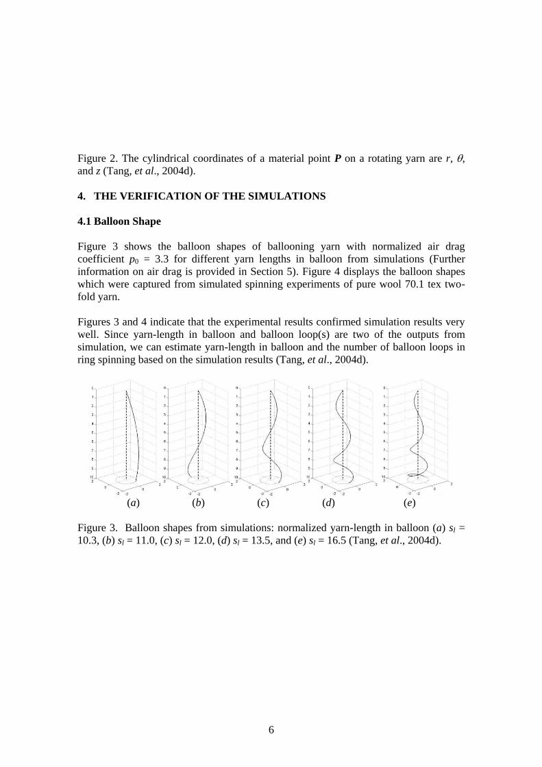
4.1 Balloon Shape
Figure 3 shows the balloon shapes of ballooning yarn with normalized air drag
coefficient p0 = 3.3 for different yarn lengths in balloon from simulations (Further
information on air drag is provided in Section 5). Figure 4 displays the balloon shapes
which were captured from simulated spinning experiments of pure wool 70.1 tex two-
fold yarn.
Figures 3 and 4 indicate that the experimental results confirmed simulation results very
well. Since yarn-length in balloon and balloon loop(s) are two of the outputs from
simulation, we can estimate yarn-length in balloon and the number of balloon loops in
ring spinning based on the simulation results (Tang, et al., 2004d).
(a) (b) (c) (d) (e)
Figure 3. Balloon shapes from simulations: normalized yarn-length in balloon (a) sl =
10.3, (b) sl = 11.0, (c) sl = 12.0, (d) sl = 13.5, and (e) sl = 16.5 (Tang, et al., 2004d).
7
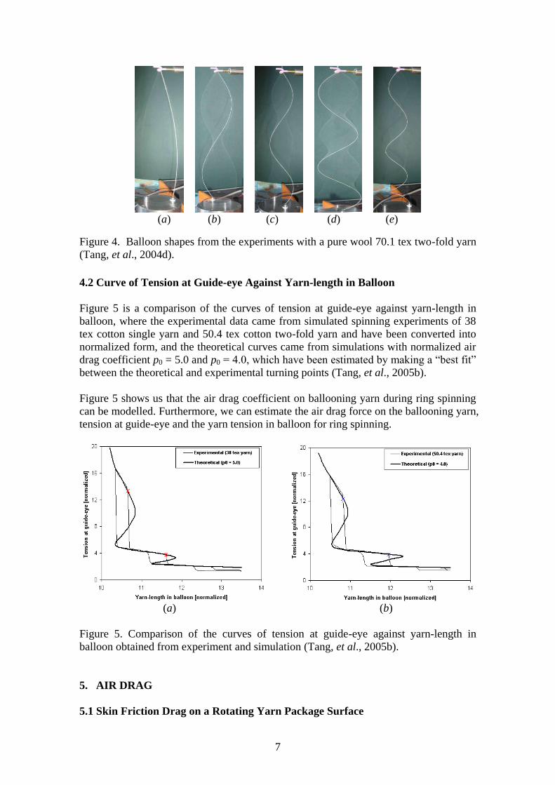
(a) (b) (c) (d) (e)
Figure 4. Balloon shapes from the experiments with a pure wool 70.1 tex two-fold yarn
(Tang, et al., 2004d).
4.2 Curve of Tension at Guide-eye Against Yarn-length in Balloon
Figure 5 is a comparison of the curves of tension at guide-eye against yarn-length in
balloon, where the experimental data came from simulated spinning experiments of 38
tex cotton single yarn and 50.4 tex cotton two-fold yarn and have been converted into
normalized form, and the theoretical curves came from simulations with normalized air
drag coefficient p0 = 5.0 and p0 = 4.0, which have been estimated by making a “best fit”
between the theoretical and experimental turning points (Tang, et al., 2005b).
Figure 5 shows us that the air drag coefficient on ballooning yarn during ring spinning
can be modelled. Furthermore, we can estimate the air drag force on the ballooning yarn,
tension at guide-eye and the yarn tension in balloon for ring spinning.
(a) (b)
Figure 5. Comparison of the curves of tension at guide-eye against yarn-length in
balloon obtained from experiment and simulation (Tang, et al., 2005b).
5. AIR DRAG
5.1 Skin Friction Drag on a Rotating Yarn Package Surface
8
5.1.1 Calculating the Skin Friction Drag on the Package Surface
As mentioned in section 3.2, a rotating full yarn package can be considered to be a
rotating cylinder. Therefore, when the package has a diameter of d [m] and a height of
h0 [m], the air drag Fp [N] on the package surface can be obtained (Anderson, 2001) by
Fp = (d)3V
2h0Cf (9)
where V [rps] is a given full spindle speed, ρ = 1.197 kg/m3 and Cf [scalar] is the skin
friction coefficient on the rotating surface.
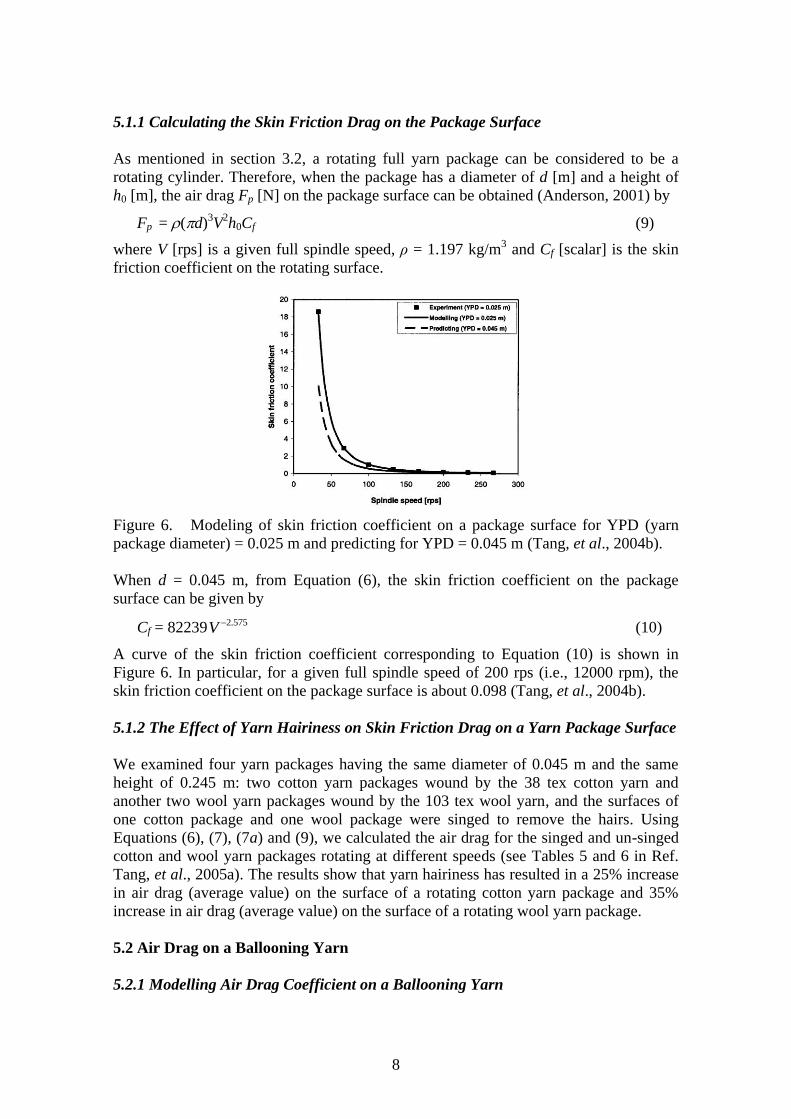
Figure 6. Modeling of skin friction coefficient on a package surface for YPD (yarn
package diameter) = 0.025 m and predicting for YPD = 0.045 m (Tang, et al., 2004b).
When d = 0.045 m, from Equation (6), the skin friction coefficient on the package
surface can be given by
Cf = 82239 575.2V (10)
A curve of the skin friction coefficient corresponding to Equation (10) is shown in
Figure 6. In particular, for a given full spindle speed of 200 rps (i.e., 12000 rpm), the
skin friction coefficient on the package surface is about 0.098 (Tang, et al., 2004b).
5.1.2 The Effect of Yarn Hairiness on Skin Friction Drag on a Yarn Package Surface
We examined four yarn packages having the same diameter of 0.045 m and the same
height of 0.245 m: two cotton yarn packages wound by the 38 tex cotton yarn and
another two wool yarn packages wound by the 103 tex wool yarn, and the surfaces of
one cotton package and one wool package were singed to remove the hairs. Using
Equations (6), (7), (7a) and (9), we calculated the air drag for the singed and un-singed
cotton and wool yarn packages rotating at different speeds (see Tables 5 and 6 in Ref.
Tang, et al., 2005a). The results show that yarn hairiness has resulted in a 25% increase
in air drag (average value) on the surface of a rotating cotton yarn package and 35%
increase in air drag (average value) on the surface of a rotating wool yarn package.
5.2 Air Drag on a Ballooning Yarn
5.2.1 Modelling Air Drag Coefficient on a Ballooning Yarn
9
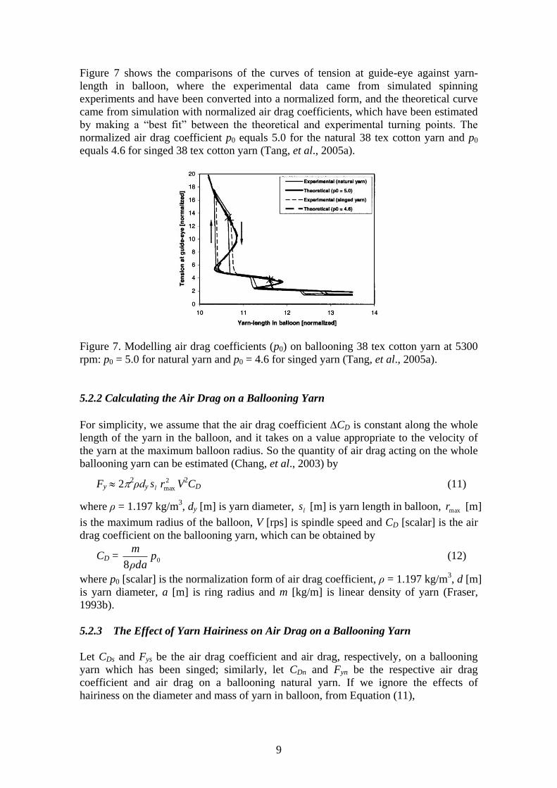
Figure 7 shows the comparisons of the curves of tension at guide-eye against yarn-
length in balloon, where the experimental data came from simulated spinning
experiments and have been converted into a normalized form, and the theoretical curve
came from simulation with normalized air drag coefficients, which have been estimated
by making a “best fit” between the theoretical and experimental turning points. The
normalized air drag coefficient p0 equals 5.0 for the natural 38 tex cotton yarn and p0
equals 4.6 for singed 38 tex cotton yarn (Tang, et al., 2005a).
Figure 7. Modelling air drag coefficients (p0) on ballooning 38 tex cotton yarn at 5300
rpm: p0 = 5.0 for natural yarn and p0 = 4.6 for singed yarn (Tang, et al., 2005a).
5.2.2 Calculating the Air Drag on a Ballooning Yarn
For simplicity, we assume that the air drag coefficient CD is constant along the whole
length of the yarn in the balloon, and it takes on a value appropriate to the velocity of
the yarn at the maximum balloon radius. So the quantity of air drag acting on the whole
ballooning yarn can be estimated (Chang, et al., 2003) by
Fy 22ρdy ls 2
maxr V2CD (11)
where ρ = 1.197 kg/m3, dy [m] is yarn diameter, ls [m] is yarn length in balloon, maxr [m]
is the maximum radius of the balloon, V [rps] is spindle speed and CD [scalar] is the air
drag coefficient on the ballooning yarn, which can be obtained by
CD = 08
pdaρ
m (12)
where p0 [scalar] is the normalization form of air drag coefficient, ρ = 1.197 kg/m3, d [m]
is yarn diameter, a [m] is ring radius and m [kg/m] is linear density of yarn (Fraser,
1993b).
5.2.3 The Effect of Yarn Hairiness on Air Drag on a Ballooning Yarn
Let CDs and Fys be the air drag coefficient and air drag, respectively, on a ballooning
yarn which has been singed; similarly, let CDn and Fyn be the respective air drag
coefficient and air drag on a ballooning natural yarn. If we ignore the effects of
hairiness on the diameter and mass of yarn in balloon, from Equation (11),
10
Fyn = 22ρdy ls 2
maxr V2CDn (13)
and
Fys = 22ρdy ls 2
maxr V2CDs (14)
where ρ = 1.197 kg/m3, dy [m] is yarn diameter, ls [m] is yarn length in balloon, maxr [m]
is the maximum radius of the balloon, V [rps] is spindle speed and CD [scalar] is air drag
coefficient on the ballooning yarn.
From Equations (12), (13) and (14), and p0n = 5.0 and p0s = 4.6 for the 38 tex cotton
yarn, we have
(Fyn – Fys)/Fys = Ds
DsDn
C
CC =
s
sn
p
pp
0
00 8.7 % (15)
Equation (15) shows that the hairiness on a ballooning cotton yarn increases the air drag
by around 9%. This can be considered to be a skin friction drag increase due to hairiness
when we ignore the effects of hairiness on the diameter and mass of yarn in balloon
(Tang, et al., 2005a).
6. THE EFFECTS OF MAIN PARAMETERS ON YARN TENSION
6.1 The Influence of Yarn Type and Count
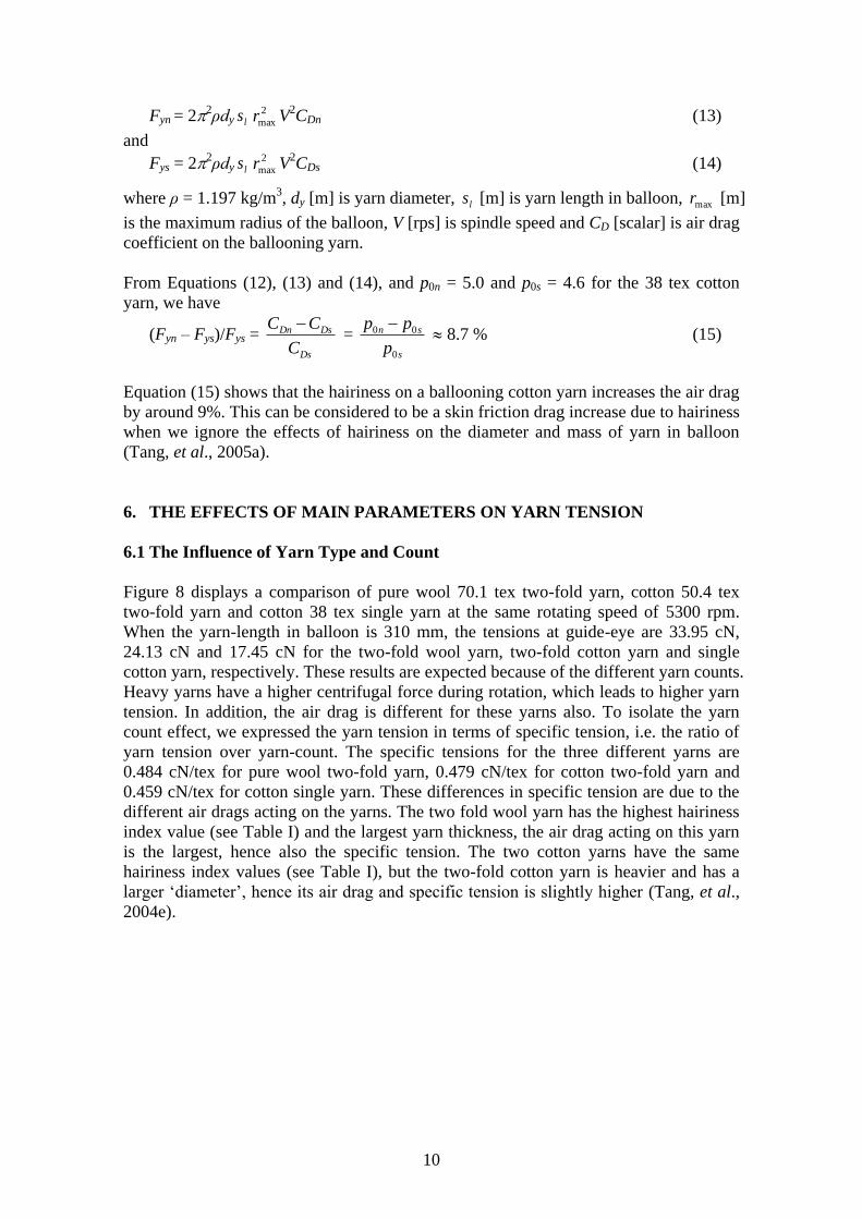
Figure 8 displays a comparison of pure wool 70.1 tex two-fold yarn, cotton 50.4 tex
two-fold yarn and cotton 38 tex single yarn at the same rotating speed of 5300 rpm.
When the yarn-length in balloon is 310 mm, the tensions at guide-eye are 33.95 cN,
24.13 cN and 17.45 cN for the two-fold wool yarn, two-fold cotton yarn and single
cotton yarn, respectively. These results are expected because of the different yarn counts.
Heavy yarns have a higher centrifugal force during rotation, which leads to higher yarn
tension. In addition, the air drag is different for these yarns also. To isolate the yarn
count effect, we expressed the yarn tension in terms of specific tension, i.e. the ratio of
yarn tension over yarn-count. The specific tensions for the three different yarns are
0.484 cN/tex for pure wool two-fold yarn, 0.479 cN/tex for cotton two-fold yarn and
0.459 cN/tex for cotton single yarn. These differences in specific tension are due to the
different air drags acting on the yarns. The two fold wool yarn has the highest hairiness
index value (see Table I) and the largest yarn thickness, the air drag acting on this yarn
is the largest, hence also the specific tension. The two cotton yarns have the same
hairiness index values (see Table I), but the two-fold cotton yarn is heavier and has a
larger „diameter‟, hence its air drag and specific tension is slightly higher (Tang, et al.,
2004e).
11
Figure 8. Yarn tension at the guide-eye against yarn-length in balloon at a rotating
speed of 5300 rpm (solid lines: tension was measured as the yarn-length in balloon was
decreased; broken lines: tension was measured as the yarn-length in balloon was
increased) (Tang, et al., 2004e).
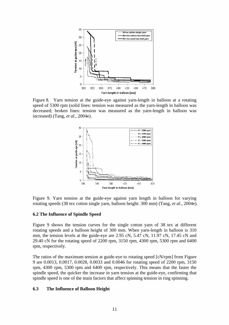
Figure 9. Yarn tension at the guide-eye against yarn length in balloon for varying
rotating speeds (38 tex cotton single yarn, balloon height: 300 mm) (Tang, et al., 2004e).
6.2 The Influence of Spindle Speed
Figure 9 shows the tension curves for the single cotton yarn of 38 tex at different
rotating speeds and a balloon height of 300 mm. When yarn-length in balloon is 310
mm, the tension levels at the guide-eye are 2.95 cN, 5.47 cN, 11.97 cN, 17.45 cN and
29.40 cN for the rotating speed of 2200 rpm, 3150 rpm, 4300 rpm, 5300 rpm and 6400
rpm, respectively.
The ratios of the maximum tension at guide-eye to rotating speed [cN/rpm] from Figure
9 are 0.0013, 0.0017, 0.0028, 0.0033 and 0.0046 for rotating speed of 2200 rpm, 3150
rpm, 4300 rpm, 5300 rpm and 6400 rpm, respectively. This means that the faster the
spindle speed, the quicker the increase in yarn tension at the guide-eye, confirming that
spindle speed is one of the main factors that affect spinning tension in ring spinning.
6.3 The Influence of Balloon Height
12
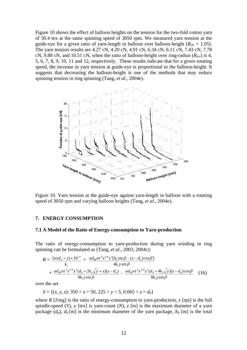
Figure 10 shows the effect of balloon heights on the tension for the two-fold cotton yarn
of 50.4 tex at the same spinning speed of 3050 rpm. We measured yarn tension at the
guide-eye for a given ratio of yarn-length in balloon over balloon-height (Rl/h = 1.05).
The yarn tension results are 4.27 cN, 4.20 cN, 4.91 cN, 6.34 cN, 6.11 cN, 7.43 cN, 7.78
cN, 9.88 cN, and 10.51 cN, when the ratio of balloon-height over ring-radius (Rh/r) is 4,
5, 6, 7, 8, 9, 10, 11 and 12, respectively. These results indicate that for a given rotating
speed, the increase in yarn tension at guide-eye is proportional to the balloon-height. It
suggests that decreasing the balloon-height is one of the methods that may reduce
spinning tension in ring spinning (Tang, et al., 2004e).
Figure 10. Yarn tension at the guide-eye against yarn-length in balloon with a rotating
speed of 3050 rpm and varying balloon heights (Tang, et al., 2004e).
7. ENERGY CONSUMPTION
7.1 A Model of the Ratio of Energy-consumption to Yarn-production
The ratio of energy-consumption to yarn-production during yarn winding in ring
spinning can be formulated as (Tang, et al., 2003, 2004c):
R = 1
3
0 10)(5
k
zd +
sin4
]cos)(sin[
1
00
324
0
yk
dzhzxad b
+
sin8
))(2(
1
020
224
0
yk
dzzykdzxad b
–
sin8
cos))(4(
1
020
224
0
yk
dzykdzxad b
(16)
over the set
S = {(x, y, z): 350 > x > 50, 225 > y > 5, 0.065 > z > d0}
where R [J/mg] is the ratio of energy-consumption to yarn-production, x [rps] is the full
spindle-speed (V), y [tex] is yarn-count (N), z [m] is the maximum diameter of a yarn
package (dp), d0 [m] is the minimum diameter of the yarn package, h0 [m] is the total
13
height of the full yarn package, [] is the chase angle of the full package, [kg/m3] is
air density and is equal to 1.197, k1 [m/rev] is a constant which relates to winding-on
velocity and full spindle-speed, k2 [(g/cm3)
-0.5] is a constant which relates to yarn
diameter and yarn-count, a and b are constants which can be determined from
experiments.
Under the following conditions: d0 = 0.025 m, h0 = 0.245 m, = 32, = 1.197 kg/m3,
k1 = 0.002 m/rev, k2 = 3.601310-5
(g/cm3)
-0.5 (the fibre density D = 1.52 g/cm
3 for the
yarn which made of cotton), a = 148030 and b = 2.575 (obtained from experiments),
then Equation (16) becomes
R = 0.1964 + 7.8540z + (0.0006425.0575.0 zyx 0.0482
21575.0 zyx
0.025535.0575.0 zyx + 142.9175
31575.0 zyx 354.2544
41575.0 zyx )×10
5 (17)
over the set
S = {(x, y, z): 350 > x > 50, 225 > y > 5, 0.065 > z > 0.025}
where R [J/mg] is the ratio of energy-consumption to yarn-production, x [rps] is full
spindle-speed (V), y [tex] is yarn-count (N), z [m] is the maximum diameter of a yarn
package (dp).
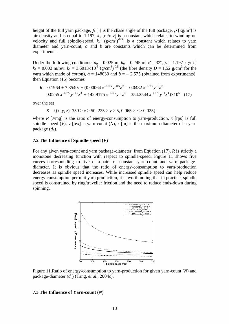
7.2 The Influence of Spindle-speed (V)
For any given yarn-count and yarn package-diameter, from Equation (17), R is strictly a
monotone decreasing function with respect to spindle-speed. Figure 11 shows five
curves corresponding to five data-pairs of constant yarn-count and yarn package-
diameter. It is obvious that the ratio of energy-consumption to yarn-production
decreases as spindle speed increases. While increased spindle speed can help reduce
energy consumption per unit yarn production, it is worth noting that in practice, spindle
speed is constrained by ring/traveller friction and the need to reduce ends-down during
spinning.
Figure 11.Ratio of energy-consumption to yarn-production for given yarn-count (N) and
package-diameter (dp) (Tang, et al., 2004c).
7.3 The Influence of Yarn-count (N)
14
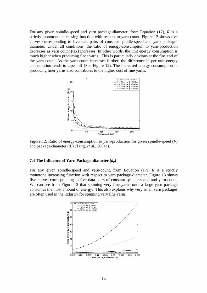
For any given spindle-speed and yarn package-diameter, from Equation (17), R is a
strictly monotone decreasing function with respect to yarn-count. Figure 12 shows five
curves corresponding to five data-pairs of constant spindle-speed and yarn package-
diameter. Under all conditions, the ratio of energy-consumption to yarn-production
decreases as yarn count (tex) increases. In other words, the unit energy consumption is
much higher when producing finer yarns. This is particularly obvious at the fine end of
the yarn count. As the yarn count increases further, the difference in per unit energy
consumption tends to taper off (See Figure 12). The increased energy consumption in
producing finer yarns also contributes to the higher cost of fine yarns.
Figure 12. Ratio of energy-consumption to yarn-production for given spindle-speed (V)
and package-diameter (dp) (Tang, et al., 2004c).
7.4 The Influence of Yarn Package-diameter (dp)
For any given spindle-speed and yarn-count, from Equation (17), R is a strictly
monotone increasing function with respect to yarn package-diameter. Figure 13 shows
five curves corresponding to five data-pairs of constant spindle-speed and yarn-count.
We can see from Figure 13 that spinning very fine yarns onto a large yarn package
consumes the most amount of energy. This also explains why very small yarn packages
are often used in the industry for spinning very fine yarns.
15
Figure 13. Ratio of energy-consumption to yarn-production for given spindle-speed (V)
and yarn-count (N) (Tang, et al., 2004c).
7.5 A Comparison of Power Distribution while Winding a Yarn Package
Supposing the diameter of an empty bobbin d0 is 0.025 m, the maximum diameter of a
full package (including bobbin and wound yarn) dp is 0.045 m, the total height of a full
package h0 is 0.245 m and the upper/lower chase angle in the cop of a full yarn package
is 32. If the yarn to be wound is made of cotton fibre with density D = 1.52 g/cm3
(Rae and Bruce, 1973) and the linear-winding on speed (i.e., front roller delivery speed)
w is 3.0 m/s, then the data in Table II can be obtained from Equations (1) – (4).
Table II. Yarn diameter, layer number, yarn length and time spent winding a package
Yarn count (N) [tex] 10 25 38 45 60 70 80
Diameter (dy) [10-4
m] 1.14 1.80 2.22 2.42 2.79 3.01 3.22
Layer number of a yarn package 538 340 276 253 219 203 190
Total length of yarn [m] 14412 5742 3809 3205 2384 2044 1789
Time taken to wind a full yarn
package (Tp) [second] 43236 17224 11427 9613 7151 6133 5369
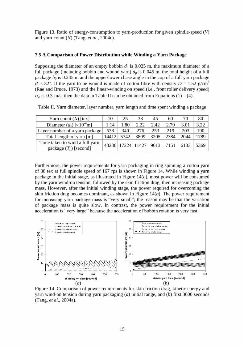
Furthermore, the power requirements for yarn packaging in ring spinning a cotton yarn
of 38 tex at full spindle speed of 167 rps is shown in Figure 14. While winding a yarn
package in the initial stage, as illustrated in Figure 14(a), most power will be consumed
by the yarn wind-on tension, followed by the skin friction drag, then increasing package
mass. However, after the initial winding stage, the power required for overcoming the
skin friction drag becomes dominant, as shown in Figure 14(b). The power requirement
for increasing yarn package mass is “very small”; the reason may be that the variation
of package mass is quite slow. In contrast, the power requirement for the initial
acceleration is “very large” because the acceleration of bobbin rotation is very fast.
(a) (b)
Figure 14. Comparison of power requirements for skin friction drag, kinetic energy and
yarn wind-on tension during yarn packaging (a) initial range, and (b) first 3600 seconds
(Tang, et al., 2004a).
16
8. CONCLUSION
A geometrical model of a bobbin with a full yarn package has been developed. The
power requirements for a yarn package process are addressed. It is found that the power
required to overcome skin friction drag is over 74% (on average) and that required to
overcome yarn wind-on tension is about 25% (on average). The power consumed by the
stored kinetic energy into a rotating yarn package can be neglected because it is less
than 1% (on average). However the power required at the spinning start-up is also quite
high (about 14%), due to the rapid package acceleration over a short period of time.
The skin friction coefficient on the package surface without hairiness depends on the
package diameter and spindle speed only. Models for predicting skin friction coefficient
on the surface of rotating cotton and wool yarn packages have been developed. The
effects of yarn hairiness on air drag on the surface of a rotating yarn package and on a
ballooning yarn were examined. The results indicate that the effect of yarn hairiness on
the skin friction coefficient on the surface of a rotating yarn package is inversely
proportional to spindle speed; and the air drag on a ballooning yarn and the average air
drag on the surface of a rotating yarn package both increase with an increase in yarn
hairiness. These results highlight the significance of yarn hairiness in ring spinning.
Realistic models of ring spinning should incorporate the effect of yarn hairiness on air
drag acting on the rotating package surface as well on the ballooning yarn.
Yarn tension at the guide-eye was measured for different yarns under different
conditions. The results indicate that yarn tension experiences a sudden drop when the
rotating yarn balloon collapses from a single loop to a double loop. Similarly, the
tension undergoes an obvious change when the balloon loops change between double
and triple, but the tension change is small when the balloon loops change between triple
and quadruple, or between quadruple and above. Yarn hairiness and thickness, through
their effects on air drag acting on the yarn, affect the measured yarn tension. The effect
of yarn rotating speed on yarn tension is very significant. In addition, yarn tension
increases when the ratio of balloon height to ring-radius increases, in particular, when
the ratio is greater than 10.
Models for predicting the ratio of energy-consumption to yarn-production for a full
package during yarn winding in ring spinning are established. The results indicate that
the ratio of energy-consumption to yarn-production is proportional to yarn package-
diameter, but is inversely proportional to spindle-speed and yarn-count. Overall, the
effect of yarn-count is greater than that of spindle-speed and package-diameter during
yarn winding in ring spinning.
The results in the present paper show that yarn winding behaviour in ring spinning can
be simulated accurately. These simulations provide an important tool to investigate the
effects of rotating speed, balloon height and yarn count on air drag force on a ballooning
yarn and yarn tension in ring spinning. This will facilitate further research into the
reduction of yarn breakage and power consumption in ring spinning.
ACKNOWLEDGMENT
17
This work was funded by a grant from the Australian Research Council (ARC) under its
Discovery project scheme. We would like to thank Dr. Lijing Wang and Mr. Chris
Hurren at Deakin University for assisting with the experimental work.
REFERENCES
Anderson, J.D. (2001) Fundamentals of Aerodynamics, 3rd edition, McGraw-Hill, Inc.,
p. 821.
Booth, J. E. (1975) Textile Mathematics (Vol. II), The Textile Institute, Manchester, p.
333.
Chang, L., Tang, Z.X., and Wang, X. (2003) “The effect of yarn hairiness on energy
consumption in rotating a ring-spun yarn package”, Textile Research Journal, 73(11),
949–954.
Fraser, W.B. (1993a) “On the theory of ring spinning”, Phil. Trans. R. Soc. Lond. A
342, 439–468.
Fraser, W.B. (1993b) “Air drag and friction in the two-for-one twister: results from the
theory”, Journal of the Textile Institute, 84(3), 364375.
John, J.E.A. and Haberman, W. L. (1988) Introduction to fluid mechanics, 3rd edition,
Prentice Hall, Englewood Cliffs, p. 288.
Rae, A. and Bruce, R. (1973) The wira textile data book, Wira Publisher, p. A30.
Tang, Z.X., Wang, X., and Fraser, W.B. (2003) "Energy consumption per unit yarn
production in ring spinning", Proceedings of the sixth engineering mathematics and
applications conference, University of Technology, Sydney, Australia, 9 – 11 July 2003
(embedded in 5th
International Congress on Industrial and Applied Mathematics,
Sydney Australia, 7 – 11 July 2003), pp. 289 – 293.
Tang, Z.X., Wang, X., and Fraser, W.B. (2004a) "Distribution of power requirements
during yarn winding in ring spinning", Textile Research Journal, 74(8), 735741.
Tang, Z.X., Wang, X., and Fraser, W.B. (2004b) "Skin friction coefficient on yarn
package surface in ring spinning", Textile Research Journal, 74(10), 845850.
Tang, Z.X., Wang, X., and Fraser, W.B. (2004c) “Minimising energy-consumption of
yarn winding in ring spinning”, Textile Research Journal, 74(12), 10971103.
Tang, Z.X., Wang, X., Fraser, W.B., and Wang, L. (2004d), “Simulations of yarn
winding in ring spinning”, The 4th
AUTEX Conference, 22-24, June 2004, Roubaix,
France.
Tang, Z.X., Wang, X., Fraser, W.B., and Wang, L. (2004e) "An experimental
investigation of yarn tension in simulated ring spinning", Fibers and Polymers, 5(4),
275-279.
18
Tang, Z.X., Wang, X., Fraser, W.B., and Wang, L. (2005a) “The Effect of Yarn
Hairiness on Air Drag in Ring Spinning”, Textile Research Journal (Accepted for
publication).
Tang, Z.X., Wang, X., Fraser, W.B., and Wang, L. (2005b), “Simulation and
Experimental Validation of a Ring Spinning Process”, Simulation Modelling Practice
and Theory (Accepted for publication).