some studies of nonlinear lateral … contractor report - - cr) h e u i some studies of nonlinear...
TRANSCRIPT

N A S A C O N T R A C T O R R E P O R T
-
- cr) h
e U
I
SOME STUDIES OF NONLINEAR LATERAL SLOSHING I N RIGID CONTAINERS
by H. Norman Abramson, Wen-Hwa Chu, and Daniel D. Kana
Prepared under Contract No. NASr-94(03) by SOUTHWEST RESEARCH INSTITUTE San Antonio, Texas
for
NATIONAL AERONAUTICS AND SPACE ADMINISTRATION WASHINGTON, D. C. J A N U A R Y 1966
https://ntrs.nasa.gov/search.jsp?R=19660006072 2018-06-23T15:47:50+00:00Z

TECH LIBRARY KAFB, NM
SOME STUDIES OF NONLINEAR LATERAL SLOSHING
IN RIGID CONTAINERS
By H. Norman Abramson, Wen-Hwa Chu, and Daniel D. Kana
Distribution of this report is provided in the interest of information exchange. Responsibility for the contents resides in the author or organization that prepared it.
Prepared under Contract No. NASr-94(03) by SOUTHWEST RESEARCH INSTITUTE
San Antonio, Texas
for
NATIONAL AERONAUTICS AND SPACE ADMINISTRATION - ~~
For sale by the Clearinghouse for Federal Scientific and Technical Information Springfield, Virginia 22151 - Price 62.00
"

1 1 1 11.1 I -. . ."

ABSTRACT
Some experimental data, primarily on total force response, are presented for nonlinear lateral slosh- ing in rigid tanks of various geometries. Some effect of excitation amplitude on liquid swirl boundaries in an open circular cylindrical tank is noted. Data for the circular cylindrical tank i s also compared with theoretical predictions. The primary nonlinear effects observed in al l tanks were decreasing response fre- quency with increasing excitation amplitude and jump phenomena.
iii

INTRODUCTION
The linearized theory of lateral sloshing of liquids in rigid containers
is now well established and its application in design procedures is routine.
Nonetheless, nonlinearities in the amplitude-frequency response of liquids
in containers of various geometries have long been noted (1 ), although
little quantitative data has been published. For example, it is evident that
even in a circular cylindrical tank undergoing lateral excitation, the liquid
free surface will form into a large amplitude breaking wave as the neighbor-
hood of each of i ts natural resonant frequencies is approached, with obvious
strongly nonlinear effects (see Fig. 1). In fact , in this particular instance,
the situation then becomes even more complex as the liquid free surface
takes on new modes of motion, arising primarily from these nonlinearit ies,
and described variously as "rotary sloshing" or ' lswirl ' l ( 2 , 3 ) .
Significant nonlinearities have been observed also in spherical
tanks (4), sector compartmented circular cylindrical tanks (5 , 6 ) , and in
long rectangular tanks in pitch (7) . Of course, the liquid response will
exhibit significant nonlinearities in a tank of almost any geometry i f the
excitation amplitude is sufficiently large, or i f mechanical baffling devices
are introduced in the tank so as to provide very large amounts of damping.
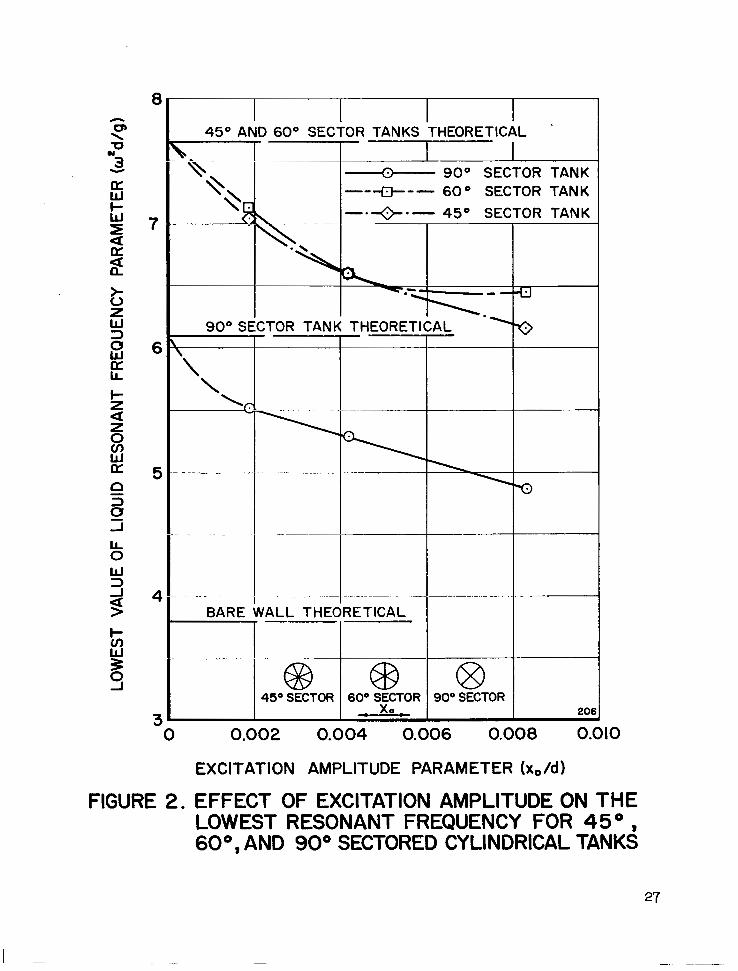
The circular cylindrical
particularly sensit ive to
tank compartmented into sectors seems to be
excitation amplitude, as shown in Figure 2 , with
1

some dependence of liquid natural frequency on excitation amplitude down
to even quite small values (6). Inasmuch as large rocket boosters are
currently being designed with sector compartmented cylindrical tanks,
such nonlinearit ies may have extremely important consequences for both
control system and structural design.
Vertical or longitudinal excitation of cylindrical tanks also leads to
interesting nonlinear motions of the l iquid free surface (8). Large amplitude
free surface motions occur when the liquid responds as a one-half subhar-
monic of the excitation and ' jump' phenomena are exhibited, as is common
to nonlinear systems.
Some laboratory investigations of interactions between contained
liquids and thin-walled elastic shells have also revealed interesting non-
linear phenomena (9, 10). The simple presence of the liquid free surface
in such an elastic shell leads to some nonlinearity in the shell wall response
but, even more startling, under certain circumstances a high frequency
small amplitude vibrational excitation of the elastic wall in a circumferential
mode may couple with the liquid and lead to a low frequency large amplitude
free surface motion of the liquid in a rotationally symmetric mode! Attempts
to describe this phenomenon analytically or to predict its occurrence have
thus far proven f rui t less , par t ia l ly because of the extreme difficulties
arising from the governing nonlinear effects whose fundamental nature even
are very poorly defined. The nonlinear aspects of large amplitude liquid
2
- . . . . . . . , , I I1 I1 I I

motions arising essentially from subharmonic response in both antisym-
metric and symmetric modes during vertical excitation are the subject
of another program of investigation (8); however, little information is
available concerning large amplitude antisymmetric modes more typi-
cal of lateral sloshing. In any event, i t is clear that much remains to
be learned concerning nonlinear liquid behavior, .and therefore it is for
this reason that the work reported in this paper was undertaken. Even
though the results reported are not yet sufficient to enable us to explain
the coupling and the characteristics of the response of both liquid and
elastic shell that have b.een observed, it is hoped that the data that
have been obtained will at least assist in defining better some of the
fundamental aspects of nonlinear lateral sloshing in r igid containers.
3

EXPERIMENTAL APPARATUS AND INSTRUMENTATION
The apparatus employed in the present study of lateral sloshing in
rigid tanks i s shown overall in Figure 3 , while closeup views of cylindrical
and spherical tanks mounted in the apparatus are shown in Figure 4.
Essent ia l ly , th is set -up is s imilar to the large SwRI slosh facility which
has been employed in many previous experimental studies of sloshing (1 1 );
however, in view of the fact that nonlinear aspects of lateral sloshing were
to be investigated in the present effort, the apparatus was designed to per-
mit considerably more precise and varied experimental observations than
were possible with the original facility.
As i s s e e n i n F i g u r e 3 , the apparatus consists of ( a ) a massive base
supporting all components of the system, (b) a carriage which may be
excited either in translation or in pitching and which in turn supports the
test tank, (c) an electrodynamic vibration exciter, and (d) an instrumentation
system. The carriage is suspended from a sub-base by four tension
springs to sustain its weight and is guided in an accurate linear motion by
four steel shafts sliding in teflon bearings mounted on the base. This
arrangement, shown in Figures 3 and 4, is for t ranslat ional exci ta t ion,
with some slight modifications being required for pitching excitation.
Circular cylindrical and spherical test tanks having inside diameters
of 7 . 7 0 in. and 7 .60 in., respectively, and fabricated from lucite plastic
4

were employed in this program, with water as the sloshing l iquid. The
tanks were mounted to the carriage by four very stiff, yet sensitive, strain-
gaged force l inks; these are similar in principle to those employed on our
l a rge r and older facility (1 1 ) except that they are provided with strain
sen.;ing elements both parallel and normal to the direction of excitation.
This part of the instrumentation system is thus designed to provide the
capability for measuring both components of the total force and moment
exerted on the tank by the sloshing liquid. The inertia signal of the empty
tank is automatically subtracted from the output signals of the force and
moment bridges by employing an inertial balancing device. This consists
basically of two accelerometers that are considerably more sensi t ive than
are the force links and mounted s o as to experience the same acceleration
as the tank, with their output signal wired to oppose that of the empty tank
in the main force link bridge. Exact cancellation can be accomplished so
that the resultant signal obtained represents only the total reaction force
or moment of the liquid on the tank. The high stiffness of the tank support
mounts is assurance that the motion of the test tank is essentially that of
the carriage; the use of semiconductor strain gages as sensing elements
in the stiff mount nonetheless provides avery sensitive monitoring system.
A 50# force output electrodynamic vibration exciter was employed
to provide an accurateandnoise-free power source, at frequencies above
about 1 . 5 cps. The displacement input was monitored by means of s t ra in
5

gages mounted on flexures supporting the shaker armature. The frequency
of this displacement signal was accurately measured on an electronic
counter so that various amplitudes and frequencies of the carriage (and
tank) displacement could readily be adjusted at the shaker console.
Additionally, a simple servo-system was uti l ized to provide automatic
constant amplitude control of displacement as frequency was varied.
Up to six liquid wave height transducers could be employed in the
cylindrical tank to observe liquid free surface displacement at various points
over the tank cross section. These transducers are of the resistive Wheat-
stone bridge type (12) that have been previously employed in similar studies
(8). Each transducer can provide the t ime variation of liquid height at a
specific point in the tank, andthus the liquid mode shapes can be readily
determined.
Each channel of instrumentation from the entire experimental
apparatus consists of some arrangement of Wheatstone bridge powered by
a corresponding channel of a CEC carrier amplifier unit, with these outputs
then recorded on a C E C char t recorder .
6

EXPERIMENTAL RESULTS
The tank configurations investigated during the course of this pro-
gram were c i rcular cyl indrical , 90" sector cylindrical, and spherical.
The basic objective of the experiments was, of course, to provide quanti-
tative data regarding the fundamental aspects of nonlinear lateral sloshing
in r igid containers; therefore, at tempts were made to measure both l iquid
free surface displacements and total forces. Because of the well-known
occurrence of swirl modes near the liquid natural frequencies ( 2 , 3 ) , the
circular cylindrical tank and the spherical tank were also investigated with
vertical spli t ter plates installed parallel to the direction of excitation to
suppress rotational motions and thus the onset of swirl. The data obtained
for each of the tank configurations :ire discussed indetail below.
Circular Cvlindrical Tank
Data were f irst obtained for the open circular cylindrical tank ( io e . ,
no vertical spli t ter plate) at a liquid depth of h / d = 1. 0. Liquid amplitude
responses in the f irst antisymmetric slosh mode are shown as a function of
excitation frequency, for several constant values of excitation amplitude
Xo/d, in Figure 5. The average liquid surface displacement at the wall
ao/d has been utilized for convenience since the actual upward displace-
ment from the mean liquid level is usually greater than the downward dis-
placement, in this mode. The average amplitude, as employed here, i s
7

one-half of the peak-to-peak amplitude value measured near the wall , in
line with the axis of excitation.
Most of the data shown in Figure 5 were obtained by maintaining
constant excitation amplitude wh-ile varying excitation frequency. At fir s t ,
data were taken only for liquid motions arising basically from the first
antisymmetric slosh mode, with no swirl occurring. Subsequently, the
boundary of the swirl region was defined experimentally by maintaining
constant excitation frequency and slowly increasing excitation amplitude
until the swirl motion began to appear. The onset of swirl could be deter-
mined relatively precisely not only by visual observation but by the appear-
ance of a significant force normal to the direction of excitation on the
oscillograph output. The swirl boundary thus obtained i s shown in Figure 5.
It should be noted that this boundary i s dependent upon both excitation fre-
quency and amplitude since in certain instances it was found that large
amplitude breaking waves could be produced without swirl. In addition, it
should be noted that within the swirl region the motion of the liquid has a
phase angle of nea r 90" with respect to the input displacement. Finally,
i t i s worth pointing out again that this mode of liquid behavior i s now ra ther
well understood analytically, with good experimental correlation for very
small excitation amplitudes ( 2 , 3) ; the data presented here in Figure 5 a r e
intended primarily to show the essential nffects of increasing excitation
amplitudes.
8

It has customarily been thought that the first antisymmetric slosh
mode i s characterized only by a rocking motion of an essentially planar
surface, departing from this only at relatively large excitation amplitudes,
However, several instances of anomalous behavior were observed during
these tests, even at quite low values of excitation amplitude. For example,
during one test run with w2d/g = 2.00 and Xo/d = 0.005 the surface dis-
placement was recorded in some detail by means of the six liquid height
transducers described earlier. The l iquid surface was found to consist
of a combination of two basic modes, the f irst antisymmetric mode at the
frequency of excitation ( 1 . 6 cps) and the f i rs t symmetr ic mode occurr ing
a s a superharmonic at double the frequency of excitation. The antisym-
metric component lagged the symmetric component significantly. A nor -
malized plot of these two components i s shown in Figure 6. While studies
of liquid motions in longitudinally (vertically) excited tanks have revealed
that both subharmonic and superharmonic liquid modes occur in abundance
( 8 ) , i t is believed that this i s the first t ime that any such observation has
been made in lateral sloshing.
Figure 7 shows dimensionless force amplitude (in the direction of
excitation) corresponding to the l iquid surface displacement data of Figure 5.
The swirl boundary has not been so well defined in this instance as before.
Half-Cylindrical Tank
In an attempt to avoid the complexities introduced by the occurrence
ul' lilt: iiquiri swirl mode, the circular cylindrical tank was modified by the
9

installation of a ver t ical spl i t ter p la te paral le l to the direct ion of excitation.
This proved to be a very effective manner in which to suppress swirl, and
therefore the complete liquid displacement response curve could be deter-
mined, as shown typically in Figure 8. Even at the quite small value of
excitation amplitude employed for this particular piece of data, the non-
l inear softening characterist ic jump phenomenon is clearly demonstrated.
Total force response data ( in the direction of excitation) are shown
in Figure 9 for several values of excitation amplitude; corresponding phase
angle data are shown in Figure 10. All of these data ere obtained byvary-
ing frequency while maintaining constant excitation amplitude; the sweep
in frequency was made by f i rs t s tar t ing at a very low value and slowly
increasing unti l substantially above f irst mode resonance, and then sweeping
back down to low values. This procedure revealed jump phenomena very
clearly. The nonlinear softening characteristic of the response curves of
Figure 9 is quite evident.
The phase angle data given in Figure 10 are really not very satis-
factory, but are included here in the interest of completeness. Figure 10a
shows leading phase angles in the frequency range below resonance; this is
believed to occur solely as the result of certain deficiencies in the instru-
mentation, andtherefore similar lead angles in this frequency range in
Figures 1 Ob and 1 Oc were arbitrari ly changed to zero values. Similarly,
the out-of-phase data do not come to 180", nor do the jumps occur in the
10

vicinity of 90"; it would appear that a consistent error of about 15" - 20"
i s p resent in a l l of thesephase angle data':.
The experimentally determined total force data are also compared
directly with some theoretical predictions in Figure 9. The calculations
result from extensions of the analysis of Hutton (3):::::. This theory i s
basically one of third order but even then accounts for only certain elements
of the nonlinear aspects of the problem; nevertheless, the theory is quite
complex in its analytical details and consequently good agreement with /
experimental data at and beyond resonance is hardly to be expected. If one
were to require the development of an improved theory, the choice between
recommending a 'bet ter ' th i rd-order theory or a similar f if th-order theory
would not be an easy one. In any event, it may be noted from Figure 9
that the agreement between theory and experiment for the in-phase branches
i s r a the r good, for all four values of excitation amplitude. The agreement
i s not so good for the out-of-phase branches. In the vicinity of resonance
the theory departs rather widely from the experimental values and, except
in Figure 9 a where the excitation amplitude has the smallest value, does
not give a good value for the frequency at which the jump occurs.
::: A somewhat different arrangement of instrumentation employed with the open circular cylindrical tank always gave zero phase angle in this region, a s should be the case; the vertical splitter plate could not have caused such shifts in phase angle without also causing changes in total force (compare with data of Fig. 7) .
::*A review of the basic theory ( 3 ) and the results of the extended analysis are given in the following section of this report .
11

90" Sector Cylindrical Tank
While significant variations in the value of the lowest liquid resonant
frequency as a function of excitation amplitude in sector compartmented
cylindrical tanks had previously been noted [ see (5 ) , ( 6 ) and Fig. 21 , i t
was felt that some study of large amplitude forced response might be of
interest. Accordingly, a quarter- tank ( 9 0 " sectors) was employed to pro-
duce the data shown in Figures 1 1 and 1 2 . Again, the phase angle data of
Figure 1 2 a.re not good but are included for completeness.
The total force response data given in Figure 11 were obtained by
slowly sweeping frequency with constant excitation amplitude, as before.
As i s wel l known ( 5 , 6 ) sector compartmented tanks exhibit liquid resonances
in sets, corresponding to the orientation of the various sectors with respect
to the direction of the excitation. For the 90" sector tank, the two la te ra l
sectors respond at the lower frequency and the fore and aft sectors at a
somewhat higher value of frequency. Thus, the forced response curves
wi l l exhibit two resonant peaks (5 ) . Looking at the response curves of
Figure 11 , however, reveals other interesting features as well; for example;
double jumps occur with each resonant peak, but both are downward from
higher to lower amplitudes:::. This arises, of course, from the fact that
the data represent the total force response of all four sectors, even though
::This interesting effect was not observed in ( 5 ) because of the limitation to very small excitation amplitudes in that work.
12
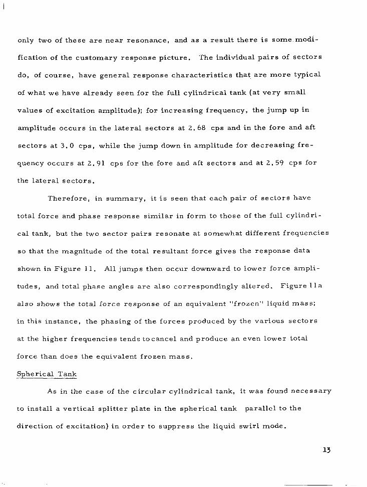
only two of these are near resonance, and a s a result there is some modi-
fication of the customary response picture. The individual pairs of sec tors
do, of course, have general response characterist ics that . are more typical
of what we have already seen for the full cylindrical tank (at very small
values of excitation amplitude); for increasing frequency, the jump up in
amplitude occurs in the lateral sectors at 2 . 6 8 cps and in the fore and aft
sec tors a t 3 .0 cps, while the jump down in amplitude for decreasing f re-
quency occurs at 2.91 cps for the fore and aft sectors and at 2.59 CPS for
the la teral sectors .
Therefore , in summary , i t i s seen tha t each pa i r of sectors have
total force and phase response similar in form to those of the full cylindri-
cal tank, but the two sector pairs resonate at somewhat different frequencies
so that the magnitude of the total resultant force gives the response data
shown in Figure 11. All jumps then occur downward to lower force ampli-
tudes, and total phase angles are also correspondingly altered. Figure 11 a
a lso shows the total force response of an equivalent "frozen" liquid mass;
in this instance, the phasing of the forces produced by the various sectors
at the higher frequencies .tends tocancel and produce an even lower total
force than does the equivalent frozen mass.
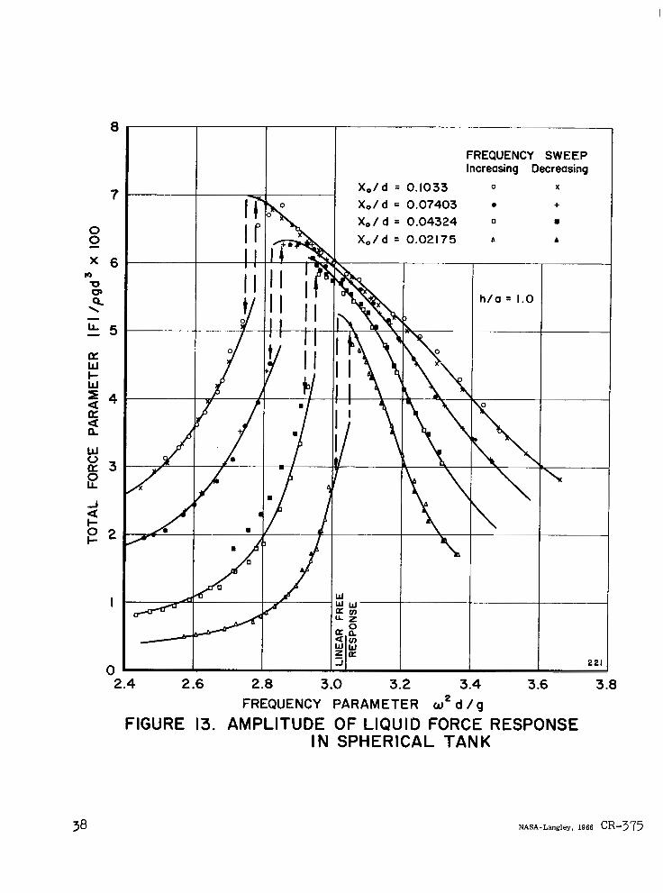
Spherical Tank
As in the case of the circular cylindrical tank, i t was found necessary
to install a vertical spli t ter plate in the spherical tank parallel to the
direction of excitation) in order to suppress the l iquid swirl mode.

Resulting total force response data (amplitude only) for a half-full tank are
shown in Figure 13. Here again, the response is seen to possess a nonlinear
softening characterist ic, which is quite sensit ive to excitation amplitude
a s had been intimated some time ago (4). However, the response curves
a r e not very well defined in the areas of the jumps, as compared with
those of the cylindrical tank, probably as a consequence of the increased
tendency of breaking waves to form because of the curvature a t the mean
liquid level (breaking wave v7ould not occur in the cylindrical tank at an
equivalent wave amplitude). The breaking waves certainly have some
tendency to modify the normal instability process in the region of the jump
frequencies; nevertheless, the jump behavior has been approximately
delineated in Figure 13 by the dashed lines. No liquid surface displacement
or phase angle data were obtained for this tank configuration.
14

I
THEORETICAL CONSIDERATIONS (Circular Cylindrical Tank)
In an effort to make some correlation between the foregoing
experimental data and theoretical predictions, a careful review of
available analyses was conducted. Of these, the theory developed by
Hutton ( 3 ) , for the circular cylindrical tank, appeared to offer most pro-
mise of being extended to yield appropriate force response information.
Brief Review of Hutton’s Theory ( 3 )
F o r a tank undergoing transverse oscillations, Hutton has assumed
that the velocity potential of the disturbance can be approximated by the
following simple form:

( N = 5 was used)
The velocity potential is Y
$6 = ;b r c u e + p ( 3 ) k
where xb = tank displacement. The form of the disturbance potential, 9 ,
equation for inviscid irrotational flow as wel l as the velocity potential.
The coefficients were to be determined’ by a combined nonlinear free sur-
face condition, to the third order.
First, by the method of expansion into the small parameter E , L A
the coefficients of E3, 2 must vanish for al l t imes.
16

In doing so , the transformations
were introduced.
'/3 For the E term to vanish, the conditions are satisfied by the
assumed forms of and z, . The 2 term contains only the constant %
t e r m and the second harmonics. There were three resultant equations
which are satisfied by the Galerkin method (or in this case the Fourier-
Bessel technique), with the assumed forms of e , )$ K2 . 4 /1 4 4 4 4
This determines /Jon , A,, , a*,, , con , c,, ) D z n i n t e rms of
.f . It is noted that the equation resulting from terms independent of t ime
is sa t isf ied by 2 = constant and that the remaining two equations yield six
/
c
equations from their components in J0 , cos (ZQ) , ,& s;o(26))
In the E term, however, only the two f i r s t harmonic t e rms were
assumed to vanish, treating time derivatives as constants.
Their 4 sin8 andTca@ components yield a set of four f irst-order nonlinear
differential equations governing ( i = 1 , 2 , 3 , 4). This set of equations
determines both the steady- state harmonic solution (when the amplitude
does not change with time) and the stability boundary (when $. var ies a s
A f C.e + steady state value of 9. .; t i smal l ) .
L

Force on the Tank::
The p res su re is given by Bernoulli's equation in t e r m s of the dis-
turbance potential, as
vvhere an arbitrary function of t ime f(f) can be absorbed into LJ
through a redefinition of @ . h d f
The x-force on the tank is given by
where Tis the f ree surface e levat ion, a is the radius of the rigid tank,
and h is the (initial) liquid depth. 6 can be evaluated to the third order,
consistent with Hutton's theory ( 3 ) , except for the contributions due to
and %which were not originally derived. Thus,
where:
::These force expressions were f i rs t der ived by D r . Kishor Doshi of SwRI.
18

and

where
A,= - A
A,= 4, 4

nond fl are given by Hutton ( 3 ) . 3 is the ampli tude of the steady- state
par t of .f , and is governed by a cubic equation depending on the motion
being planar or nonplanar::.
Results
2n
/
A s descr ibed and discussed previously, total force response data
calculated from the foregoing theory have been compared with relevant
experimental data in Figure 9.
n ‘:Through private commu$cations with D r . Hutton, it was learned that 2-
in the expressions for 6, and G2 should be replaced b y 1 ” 93 in order to calculate 7 correc t ly .
A 9
9 3

CONCLUSIONS AND RECOMMENDATIONS
This study of some of the gross nonl inear character is t ics of lateral
sloshing in rigid containers, exploratory though it was, has revealed a
number of important and interesting features. While the character of the
force response in circular cylindrical and spherical tanks may have been
entirely as anticipated, that in sector compartmented tanks certainly was
not. In fact, the phasing of forces between sectors led to a total response
picture of somewhat unique nature. The continued use of compartmented
tanks in actual vehicle design would certainly indicate the desirability of
further investigations along these lines
Theoretical developments are woefully lacking. Even the best
avai lable theory for the c i rcular cyl indrical tank is quite poor, except for
the in-phase branch at low amplitudes. Efforts to develop a nonlinear
theory for the sector compartmented tank should be init iated as promptly
as possible.
22

ACKNOWLEDGEMENTS
The authors are very much indebted to J . E.. Modisette for performing most of the experiments and analyzing the data, with the assistance of R. B. Stiles; to I?. S . Westine and R . Gonzales for per- forming some analyses and many compu- tations; and to V. Hernandez for preparing the f igures.

REFERENCES
1.
2 .
3.
4.
5.
6.
7.
8 .
9.
Abramson, H. N., "Dynamic Behavior of Liquids in Moving Containers, ' I Applied Mechanics Reviews, 16, 7 , pp. 501-506, July 1963.
-
Berlot , R. R. , l lFroduct ion of Rotation in a Confined Liquid Through Translational Motions of the Boundaries, I ' Journal of Applied Mechanics, - 26, 4, pp. 513-516, December 1959.
Abramson, H. N o , C a r z a , Lo R., and Kana, D. D., "Liquid Sloshing in Compartmented Cylindrical Tanks, ' I ARS Journal, 32, 6, pp. 978-980, June 1962.
-
Abramson, H. N., and Garza, L. R. "Some Measurements of Liquid Frequencies and Damping in Compartmented Cylindrical Tanks, I ' AIAA Journal of Spacecraft and Rockets, to appear.
~ ~ 1 ~ ~ 1 1 , J. F., c h u , W . H., and Modisette, J . E. 9 ' 'Studies Of
Ship Roll Stabilization Tanks, I ' Tech. Rept. No. 1 , Contract Konr-3926(00), Southwest Research Institute, August 1964.
Dodge .) F, T o , Kana, D. D o , and Abramson, H. N., "Liquid Surface Oscillations in Longitudinally Excited Rigid Cylindrical Containers, AIAA Technical Paper 65-83 (also, AIAA Journal, i n p re s s ) .
Lindholm, uo S., Kana, D. D o , and Abramson, H. N o ' 'Breathing Vibrations of a Circular Cylindrical Shell with an Internal Liquid, I '
Journal of the Aerospace Sciences, 29, 9, pp. 1052-1059, September 1962.
-
24

10. Kana, D. D . , Lindholm, U. S . , and Abramson, H. N . , "An Experimental Study of Liquid Instability in a Vibrating Elastic Tanlc, Tech. Rept. No. 5 , Contract NASw-146, Southwest Research Institute, January 1963.
11. Abramson, H. N . , and Ransleben, G. E . , J r . , "Simulation of Fuel Sloshing Characterist ics in Missile Tanks by Use of Small Models, I ' ARS Journal, - 30, 7, pp. 603-612, July 1960.
12. Kana, D. D . , "A Resistive Wheatstone Bridge Liquid Wave Height Transducer , ' I Tech. Rept. No. 3 , Contract NAS8-11045, Southwest Research Institute, May 1964.

FIGURE 1. LARGE AMPLITUDE BREAKING WAVE DURING LATERAL SLOSHING NEAR FIRST MODE RESONANCE
26
8
7
6
5
4
3
450 AND 600 SECTOR TANKS THEORETICAL ' I 90° SECTOR TANK """ 60° SECTOR TANK
--.+.- 45O SECTOR TANK
90° SECTOR TANK THEORETICAL I"
. . . I
BARE WALL THEORETICAL
I I
0.002 0.004 0.006 0.008 0.010
EXCITATION AMPLITUDE PARAMETER (x,/d)
FIGURE 2. EFFECT OF EXCITATION AMPLITUDE ON THE LOWEST RESONANT FREQUENCY FOR 45O 600, AND 900 SECTORED CYLINDRICAL TANK^

FIGURE 3. EXPERIMENTAL APPARATUS FOR LATERAL SLOSHING
28

( a ) CYLINDRICAL TANK
( b ) SPHERICAL TANK FIGURE 4. MOUNTING DETAILS OF TANKS IN TEST APPARATUS

0.30
0.25 U \
0 0
1 -I
L
a 3 0.20
a I-
w n 3 I- Z 0.15 a z a 0 3 0 - A 0.10 W c3
U W >
a
a 0.05
FIRST ANTISYMMETRIC MODE h / d = 1.0
Xo/d
A = 0.0227 0 = 0.0172 0 = 0.0115 0 = 0.0056
! X,/d
0 = 0.0021 @ = 0.0012
- @ = 0.00067- @ = 0.0025 8 = 0.0099 @ = 0.022
I 2 3 4 5 6 FREQUENCY PARAMETER w d /g
FIGURE 5. LIQUID FREE SURFACE RESPONSE IN CIRCULAR CYLINDRICAL TANK SHOWING SWIRL REGION

-4 -3 -2 - I 0 I 2 3 4 RADIAL LOCATION - INCHES
FIGURE 6. SYMMETRIC AND ANTISYMMETRIC COMPONENTS OF LIQUID SURFACE DISPLACEMENT IN CIRCULAR CYLINDRICAL TANK

I
I I FIRST ANTISYMMETRIC MODE
h / d = 1.0
A = 0.0227 - 0 = 0.0172 0 = 0.01 15 0 = 0.0056
- I
FIGURE 7.
X,/d
0 = 0.0021 @ = 0.0012
~ @ = 0.00067 8 = 0.0025 @ = 0.0099 @ = 0.022
2 3 4 " 5 6 FREQUENCY PARAMETER d d /g
LIQUID FORCE RESPONSE IN CIRCULAR CYLINDRICAL TANK

0.18
0.16
0.14 -0 \
0
-I
0 - 2 0.12 3
a I-
0.10 3 k -I
H a
a 0.08 n - 3 0 -I - w 0.06 a c3
U W > a 0.04
0.02
3.0 3.5 4.0 4.5 5 .O FREQUENCY PARAMETER u * d / g
FIGURE 8. LIQUID FREE SURFACE RESPONSE IN HALF-CYLINDRICAL TANK DEMONSTRATING NONLINEAR CHARACTERISTICS
33

"2.0 2.5 3.0 3.5 4.0 4.5 5.0 FREQUENCY PARAMETER w2 d/g
., 2.0 2.5 3.0 3.5 4.0 4.5 5.0
FREQUENCY PARAMETER wed / g
" I 2.0 2.5 3.0 3.5 4.0 4.5 5.0
FREQUENCY PARAMETER w 2 d / g
2 2 ".i- 0 I-
- - ijl
0 2.0 2.5 3.0 3.5 4.0 4.5 5
FREQUENCY PARAMETER wz d /g
h/d 1.0 0 0 0 INCREASING FREQUENCY X X X DECREASING FREOUENCY
-EXCITATION-
FIGURE 9. AMPLITUDE OF LIQUID FORCE RESPONSE
0
IN HALF-CYLINDRICAL TANK
34

X./d = 0.00831
2.0 2.5 3.0 3.5 4.0 4.5 5.0 FREQUENCY PARAMETER w d i g
2
- - - EXCITATION
h/d = 1.0 0 0 0 INCREASING FREQUENCY X X X DECREASING FREQUENCY
FIGURE IO. PHASE ANGLE OF LIQUID FORCE RESPONSE IN HALF-CYLINDRICAL TANK
35

X
mz 3.0
\
LL
P
- - 2.5 IL W I- % 2.0 a ' 1.5
IL
W V IL 0
-I IL 1.0
2 0 I- 0.5
04.0 4.5 5.0 5.5 6.C
6.0
0 5.5 0
"o, 5.0 X
P
- \ LL - 4.5 IL W i- W > 4.0 a a a IL
3.5 V IL z 3.0 J
I- O !- 2.5
a
2 .Q
,00356
FREQUENCY PARAMETER
~
X./ d = 0.00915
I 1 - - Sector 2 4 Resonana
. . .
w 2 d / g
FREQUENCY PARAMETER w 2 d / g
FIGURE II. AMPLITUDE OF
@ 4
t
EXCITATION
h/d = 1.0 0 0 0 INCREASING FREQUENCY x x x DECREASING FREQUENCY
LIQUID FORCE RESPONSE IN 90° SECTOR CYLINDRICAL TANK

I I
Xo/d = 0.00356 loo r, Xo/d =0.00551
4.0 5.0 6.0 7.0 8 .O 9.0 10.0 4.0 5.0 6.0 7.0 8.0 9.0 FREQUENCY PARAMETER W * d i g FREQUENCY PARAMETER w e d / g
@ 4 h/d = 1.0 0 0 0 INCREASING FREQUENCY
- - x x x DECREASING FREQUENCY
EXCITATION
FIGURE 12. PHASE ANGLE OF LIQUID FORCE RESPONSE IN 90° SECTOR CYLINDRICAL TANK
FREQUENCY SWEEP Increasing Decreasing
h/a = 1.0 I 221
2.4 2.6 2.0 3 .O 3.2 3.4 3.6 3.0 FREQUENCY PARAMETER o2 d / g
FIGURE 13. AMPLITUDE OF LIQUID FORCE RESPONSE IN SPHERICAL TANK
NASA-Langley, 1966 CR-375