south kramer avenue landslide: jacobs circle to emmons ... · recommendations regarding the south...
TRANSCRIPT

South Kramer Avenue Landslide: Jacobs Circle to Emmons Street
Sitka, Alaska
February 2, 2016
Submitted To: Mr. Michael Harmon, P.E.
Public Works Director City and Borough of Sitka, Alaska
100 Lincoln Street Sitka, Alaska 99555
By: Shannon & Wilson, Inc.
400 N 34th Street, Suite 100 Seattle, Washington 98103
21-1-22168-001

ALASKA CALIFORNIA
COLORADO FLORIDA
MISSOURI OREGON
WASHINGTON WASHINGTON DC METRO
WISCONSIN
400 NORTH 34TH STREET, SUITE 100 P.O. BOX 300303 SEATTLE, WASHINGTON 98103-8636 206-632-8200 FAX: 206-695-6777 www.shannonwilson.com 21-1-22168-001
February 2, 2016 Mr. Michael Harmon, P.E. Public Works Director City and Borough of Sitka, Alaska 100 Lincoln Street Sitka, AK 99555 RE: SOUTH KRAMER AVENUE LANDSLIDE: JACOBS CIRCLE TO
EMMONS STREET, SITKA, ALASKA
Dear Mr. Harmon: This letter report presents our research, observations, discussions, analyses, conclusions, and recommendations regarding the South Kramer landslide that occurred in Sitka, Alaska, on August 18, 2015. The landslide caused three fatalities, the destruction of one residence, and the damage of another residence. It is our understanding that more than 50 landslides were documented to have occurred in the Sitka area on August 18 (Prussian, 2015). The purpose of our work is to aid the City and Borough of Sitka (CBS) in understanding the landslide in relation to the existing Kramer Avenue residential development and to offer input to CBS as it considers future development in this area. This study concentrated on the portion of Kramer Avenue between Jacobs Circle and Emmons Street.
The scope of Shannon & Wilson, Inc.’s (Shannon & Wilson’s) services included:
1. Review of existing published geologic literature and scientists’ reports about the recent landslide.
2. Discussions with local officials and scientists familiar with the geology and the August 18, 2015, landslide.
3. Field reconnaissance of the lower part of the Harbor Mountain hillside and the Kramer Avenue residential development between Jacobs Circle and Emmons Street.
4. Runout analysis of the debris flow.
5. Meetings with the CBS Assembly and staff.
6. Preparation of this report with our findings.

Mr. Michael Harmon, P.E. City and Borough of Sitka, Alaska February 2, 2016 Page 2 of 11
21-1-22168-001-L1/wp/lk 21-1-22168-001
Our work was authorized in a contract signed by Mr. Mark Gorman, CBS city administrator, on November 11, 2015. The contract was amended on December 9, 2015, to include a limited field reconnaissance.
SITE DESCRIPTION
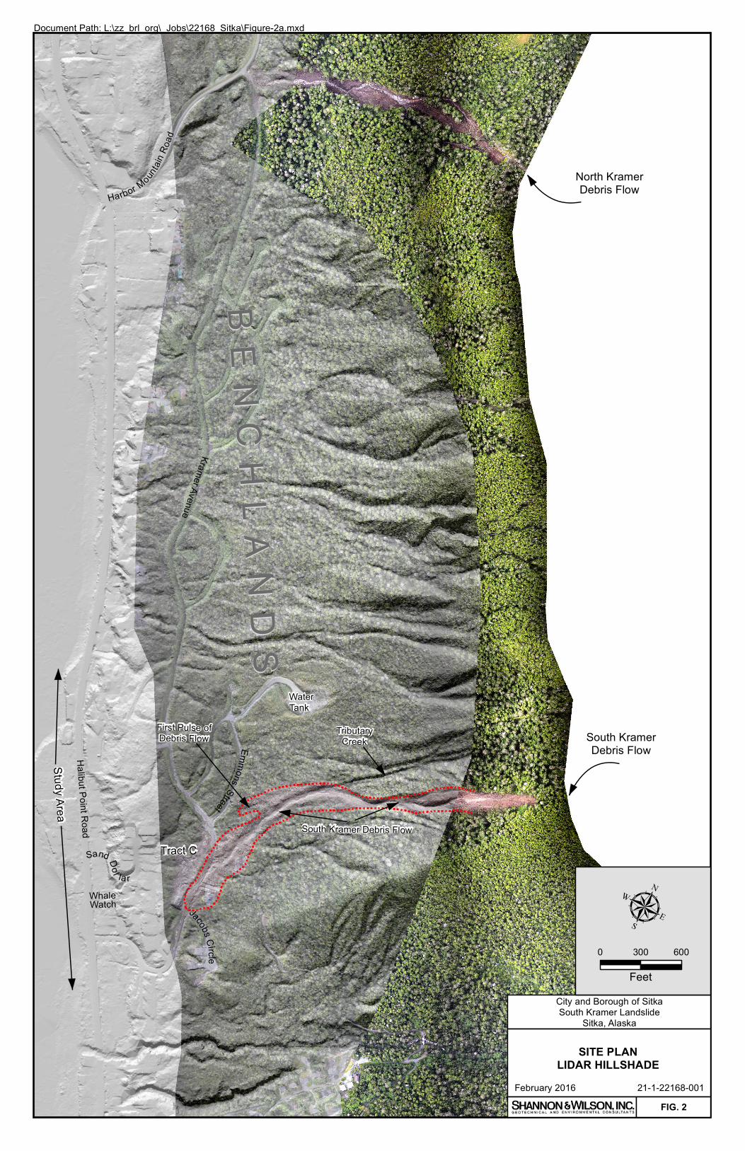
The South Kramer landslide is located north of downtown Sitka on the western flank of Harbor Mountain, as shown in the Vicinity Map, Figure 1. It initiated near the top of a ridge, at the southern end of the west-facing slope of Harbor Mountain. The debris from the debris flow came to rest near the southern end of Kramer Avenue, as shown in Figure 2.
The topography in the vicinity of the landslide is variable. Harbor Mountain rises to about elevation 2,000 feet. The face of the mountain has slope inclinations that exceed 100 percent, and the slope on which the landslide initiated reportedly is inclined at about 85 percent (Landwehr and others, 2015). The slope maintains inclinations steeper than 70 percent down to between elevations 260 and 320 feet at which point it gradually flattens. Along Kramer Avenue, the slope inclination is reduced to 12 to 14 percent.
Kramer Avenue is located on a terrace that is about 400 to 600 feet wide and is continuous for about one and a quarter miles (Figure 2). This area is locally known as the “Benchlands.” From the western edge of the Benchlands, the slope steepens down through the residential areas of Sand Dollar Drive and Whale Watch Drive. Another terrace is located to the west of these streets. Halibut Point Road is situated on this lower bench, a raised marine terrace. The sea is directly west of Halibut Point Road.
Little of Kramer Avenue is presently developed. Roads along the Benchlands are in place. A water tank is constructed on the slope above the northern end of Emmons Street (Figure 3), and distribution is established to the south of it. A sewer main extends from the southern end of Kramer Avenue northward to the Emmons/Kramer intersection. The only part of Kramer Avenue on which residences have been built is the southern end. One of these houses was destroyed by the landslide; another was damaged. Several other houses further south were undamaged.
The natural vegetation on the mountainside consists of a dense stand of conifers, including spruce and hemlock, and intermixed stands of red alder (USKH, Inc., 2008). Undergrowth is highly variable, ranging from very dense to sparse. We understand that the west-facing side of

Mr. Michael Harmon, P.E. City and Borough of Sitka, Alaska February 2, 2016 Page 3 of 11
21-1-22168-001-L1/wp/lk 21-1-22168-001
Harbor Mountain has not been logged by the U.S. Forest Service. On the private property to the west of the U.S. Forest Service property, trees have been removed for the Benchlands streets and for utilities and residential lots at the southern end of the Benchlands.
We understand the landslide occurred at about 9:30 a.m. on August 18, 2015. It initiated on undisturbed U.S. Forest Service forest land near elevation 1,350 feet, traveled about 3,000 feet down an unnamed channel (Gould and others, 2015), and ended at about elevation 110 feet on Kramer Avenue. The upper part of the headscarp (Figure 2) is located at a drainage divide between the west- and south-facing slopes of Harbor Mountain. The initiation zone was estimated to be about 50 (Landwehr and others, 2015) to 85 feet wide (Gould and others, 2015), 90 feet long, and 6 to 10 feet deep (Landwehr and others, 2015). Along its path, it locally deposited but mostly scoured the channel of colluvium. In the upper portion of the path, the channel was scoured to bedrock (Figure 4). The path ranged from 40 to 70 feet wide, as shown in Figure 5. We understand that soil is exposed in the headscarp, but no additional blocks of cracked or detached soil are imminently in danger of falling from the headscarp (Prussian, 2015).
From aerial photographs and from field observations, it appears that the first pulse of the debris flow left the channel and plowed into the woods near elevation 240 feet, as indicated in Figures 2 and 3. This was likely the result of an upslope, straight segment of the channel and the debris wanting to maintain a straight line. After the first pulse, the bulk of the debris followed the existing channel that was directed toward the residence at 430 Kramer Avenue. The debris killed three people, and destroyed one residence and damaged another. Upon reaching Kramer Avenue, the debris encountered a low berm on the south side of the road that appears from photographs to have been 2 to 3 feet higher than Kramer Avenue. Farther south along the western side of Kramer Avenue, fill was mounded 8 to 10 feet high in an earthfill berm. When the debris flow encountered these berms, it turned southward down the road. It came to a stop about 400 feet from the point at which it reached Kramer Avenue, as shown in Figures 2, 3, and 6.
We understand that the more southerly earthfill berm (Figure 6) is a temporary stockpile of soil that was placed by the development contractor for future site grading in Tract C.
WEATHER
We understand that the Sitka area had incurred above-normal precipitation in the 2½ months before the August 18 landslide. For June and July 2015, rainfall was 15.13 inches, whereas the

Mr. Michael Harmon, P.E. City and Borough of Sitka, Alaska February 2, 2016 Page 4 of 11
21-1-22168-001-L1/wp/lk 21-1-22168-001
normal total for those two months is 7.0 inches; more than double the normal (YourWeather Service, 2015). For August 2015, 3.23 inches of rain had fallen in the first 17 days of the month, about normal rainfall.
On August 18, an anomalous area of upper level high pressure was positioned over the northeastern Pacific. This upper level pattern steered a heavy rain system toward the central Alaska panhandle (Jacobs and others, 2015) on August 18.
Between 4:00 and 10:00 am on August 18, the Sitka area received 2.5 to 3.25 inches of precipitation, considered by the National Weather Service to be a, “very exceptional and extreme weather and hydrologic event.” (Jacobs and others, 2015) The National Weather Service reported that rainfall in the mountains of the Sitka area could have exceeded the recorded amounts due to orographic effects. Moderate winds of 11 to 17 miles per hour from the southwest were recorded at the Sitka Airport during this storm.
GEOLOGIC CONDITIONS
Harbor Mountain is geologically diverse, comprised of metamorphic bedrock and glacial, volcanic, and mass wasting soils. The mountain is cored by Sitka greywacke, a slightly metamorphosed sandstone (Karl and others, 2015). The rock is moderately hard, light brown, and fine to medium grained. In the Kramer Avenue area, it outcrops sporadically in road cuts along Kramer Avenue and Halibut Point Road.
The greywacke is overlain by glacial till, a compact to dense, gray, poorly graded gravel with silt, sand, and cobbles (Yehle, 1974; Golder Associates, 2008). The till probably covers bedrock throughout the area, but is only exposed in several road cuts. It stands steeply in the cuts, because it was overridden by ice. Test pits logged by Golder Associates indicate that the till is at least 2 feet thick to more than 13 feet thick in the subject area. Only one test pit encountered bedrock beneath the till.
Till is overlain by volcanic ash, a product of eruptions of Mount Edgecumbe. The ash at the Kramer Avenue site is reportedly comprised of deposits from two eruptions (Rhiele, 1996). The ash is described in the Golder Associates report as loose to compact, brown, gray, red, and yellow, silty sand with a trace clay. This report indicates that the deposit (two combined eruptive

Mr. Michael Harmon, P.E. City and Borough of Sitka, Alaska February 2, 2016 Page 5 of 11
21-1-22168-001-L1/wp/lk 21-1-22168-001
deposits) is 1.5 to 7 feet thick in the study area. One test pit did not expose ash. It was observed in all road cuts in the Kramer Avenue area.
Locally draping the above geologic units is landslide debris. This diamict is a mixture of the weathered bedrock, till, and ash. It is described as compact, gray, silty sand with trace clay, gravel, cobbles, and boulders in the Golder Associates report, and ranges from 1.5 to 18.5 feet thick where encountered. Four of the 12 test pits in the study area contained no landslide debris. It appears to have accumulated in the Benchlands at the foot of debris flow channels that head on Harbor Mountain. No surficial exposures of landslide debris were observed. Our only knowledge of its locations and characteristics in the study area comes from the Golder Associates report.
Groundwater is perched in this area. In the Golder report, groundwater levels ranged from 1.5 to 8.5 feet below ground surface. Numerous springs, as noted in Figure 3, emerge from the hillside. In some cases, they form the heads of through-going surface streams. In other cases, they infiltrate back into the ground and pop out farther downslope. In some areas, such as Tract C, most of the ground is covered with standing water, likely perched on ash or till.
The Light Detection and Ranging (LiDAR) hillshade image (Figure 2) of the study area is informative but enigmatic. On a very broad scale, it has been suggested by others that the west-facing slope of Harbor Mountain collapsed in ancient times, spreading landslide debris into the ocean, one remnant of which is a shoreline protrusion. There is no evidence in outcrop or exposure of debris of such a widespread event, and the LiDAR image does not unequivocally support such a hypothesis.
The LiDAR image does support the hypothesis that the Benchlands is, in part, constructed of landslide materials supplied by repeated debris flows along several discrete chutes that originate on Harbor Mountain. The depositional distribution of the landslide debris also supports this idea. No landslide debris is observed or reported to the west of Kramer Avenue.
CONCLUSIONS
In our opinion, the South Kramer debris flow was a natural event. There is no evidence that human actions, past or recent, had an influence on the initiation of this landslide. Five
Mr. Michael Harmon, P.E. City and Borough of Sitka, Alaska February 2, 2016 Page 6 of 11
21-1-22168-001-L1/wp/lk 21-1-22168-001
contributing factors that appear to have influenced this mass wasting event are: (a) above-normal precipitation in the 2½ months prior to August 18, (b) very steep slopes in the initiation zone, (c) a bedrock hollow that concentrated groundwater and channeled failed soil to the bottom of the slope, (d) weak soil in the initiation zone, and (e) exposure to high winds on the initiation ridge.
The intense storm of August 18, 2015, was judged to be extraordinary by the National Weather Service. This extraordinary event was added to 2½ months of more than twice the normal precipitation for Sitka. The rainfall intensity combined with the other contributing factors was the major factor for this landslide, in our opinion. Debris flows normally initiate on slopes steeper than about 70 percent. The inclination of the slope at the initiation zone of this debris flow was 85 percent, and susceptible to failure.
Bedrock hollows, areas where the topography is convergent, are at particular risk of failure because they are capable of concentrating groundwater, thereby lowering the stability of accumulated soils in the swale.
The soils in the headwall of the debris flow consisted of colluvium, ash, and glacial till. The colluvium is weak because it accumulated from sloughing of surrounding formations. The ash is also weak because it was never overridden and compacted by glacial ice and has low strength. Ash soils are also typically hydrophylic and impermeable creating perched water and can cause an elevated groundwater level in the soil above it.
Although high winds may not have been recorded at the Sitka Airport on August 18, the position of the landslide initiation zone is on a ridge that is vulnerable to south and southwestern winds. During strong winds, the trees in this area would be especially prone to rocking and opening up cracks in the ground surface, thereby allowing relatively fast infiltration of rainfall. Studies in southeastern Alaska have shown wind and windthrow to be a factor in landslides (Buma and Johnson, 2015) in the region.
RUNOUT ANALYSIS
In order to assess the potential future risk to infrastructure and residential development in the Kramer Avenue area between Jacobs Circle and Emmons Street, runout modeling was performed using an empirical-based computer program developed for debris flows in the Queen Charlotte

Mr. Michael Harmon, P.E. City and Borough of Sitka, Alaska February 2, 2016 Page 7 of 11
21-1-22168-001-L1/wp/lk 21-1-22168-001
Islands at the University of British Columbia (Fannin and Bowman, 2007). We judge this program to be appropriate for use in Sitka owing to its regional application, and the similarity of topography of western British Columbia terrain and that of southeastern Alaska.
The model utilized is UBCDFLOW, in which the main factors are the initial volume in the initiation zone, and the channel widths and runout slope angles over channel reaches of similar character (University of British Columbia [UBC] Civil Engineering Department, 2014). The channel widths and runout angles were readily obtained by recent LiDAR data and photographs; however, the initial volume of soil is based on observations by others, and only a best estimate, because the shape of the original topography in the headscarp area cannot be known.
We performed several iterations of the model to calibrate it, and then ran five scenarios (see Figure 3):
1. The full length of the channel along which the August 18 debris flow moved, deflected by the berms on the west side of Kramer Avenue (Terminus 1).
2. The full length of the channel along which the August 18 debris flow moved, if the berms along the west side of Kramer Avenue had not been in place (Terminus 2).
3. The northern tributary chute originating at the top of Harbor Mountain, deflected by the berms on the west side of Kramer Avenue (Terminus 3).
4. The northern tributary chute originating at the top of Harbor Mountain without the berms on the west side of Kramer Avenue (Terminus 4).
5. The northern branch of the August 18 debris flow that ended in the woods uphill from Kramer Avenue (Terminus 5).
The locations of the distal ends of the modeled runouts are presented in Figure 3. Modeling indicated that another debris flow along the August 18 alignment would end up in the same place as before, assuming that the berms on the west side of Kramer Avenue were left in place. If the berms were not in place on August 18, the debris could potentially have runout into Tract C about 400 feet southwest of Kramer Avenue. If the August 18 debris flow deposit had continued straight westward through the woods, as shown in Figures 2 and 3, it could have reached Kramer Avenue. Modeling of this side branch of the debris flow showed that once the debris flow material leaves the channelized section of the creek and becomes a uniform unchannelized slope, the debris slows and deposits relatively quickly, as shown in Figure 3. The modeling does not

Mr. Michael Harmon, P.E. City and Borough of Sitka, Alaska February 2, 2016 Page 8 of 11
21-1-22168-001-L1/wp/lk 21-1-22168-001
take the roughness of the in-place trees into account, so it would probably come to rest sooner than the model indicates.
The bedrock hollow in the August 18 initiation zone has mostly emptied out and the channel below has been scoured, so the future hazard from that source is likely low; however, a tributary creek/hollow to the north that extends to the top of Harbor Mountain has the potential to fail and recreate a similar or larger debris flow than the August 18 event. This bedrock hollow is about 700 feet higher in elevation than the initiation zone of the August 18 debris flow.
If this higher bedrock hollow failed in a manner similar to the August 18 debris flow, the model predicts that it would flow down Kramer Avenue about 400 feet beyond the Kramer Avenue debris deposit, assuming the berms were in place. Without the berms in place, this modeled debris flow would move about 580 feet southwest of Kramer Avenue, reaching residences on the eastern side of Whale Watch Drive and Sand Dollar Drive.
RISK ZONES AND DEVELOPMENT RECOMMENDATIONS
The implication of the runout analysis is that residences, utilities, and roads in the path of the identified potential debris flow paths are at high risk. However, the modeling analysis cannot be relied upon singularly. It is a supplement for geologic judgment and experience. In the case of the southern end of Kramer Avenue, the use of LiDAR hillshade images is most instructive. They show the corridors of erosion/incision and deposition, as well as relative ages of the related landforms, factors of particular importance in informing land use decisions.
Based on our assessment of the modeling, field observations, and LiDAR images, we have created three categories of risk in the Jacobs Circle/Emmons Street area for debris flows originating on Harbor Mountain. The three categories described below range from high to low. There are no no-risk zones in the study area.
The high-risk zone is in and adjacent to the recent debris flow path and two other debris flow paths that were identified in the field and on the LiDAR hillshade image. They have incised channels and uneven, hummocky, and lobate topography. We recommend no new residential development or transportation and utility corridors through this area without extensive study and protective measures. If any new development or redevelopment is contemplated for these areas, a geotechnical evaluation should be performed by a licensed civil engineer specializing in

Mr. Michael Harmon, P.E. City and Borough of Sitka, Alaska February 2, 2016 Page 9 of 11
21-1-22168-001-L1/wp/lk 21-1-22168-001
geotechnical practice or professional geologist experienced in mass wasting processes. The evaluation should include subsurface explorations, evaluation of the hazard and risk from debris flows, and design of debris flow mitigation or protective measures. Such reports should be reviewed by a third-party for completeness and appropriateness.
Some existing residences are in the high-risk zone. Although this report does not attempt to assess or predict the risk to any individual parcel or structure, it may be prudent for those property owners to evaluate their exposure, obtain professional assistance, and take protective action, as discussed above.
Three moderate risk zones were identified, as shown in Figure 3. They are either buffer areas between high- and low-risk zones, or areas that offer slightly higher risk than low, as discussed below. One is the buffer zone adjacent to the debris chute high-risk zone on the northern edge of the study area. Another buffer zone is located downhill (west) of Tract C. Another moderate zone is located uphill of Emmons Street where there appear to be deposits of ancient, relict debris flows. The channel that originally supplied debris to this area is presently incapable of delivering debris to this same area, in our opinion; however, if the adjacent incised creek/swale should become blocked during a debris flow, the relict channel could potentially deliver debris to this area again. If any new development or redevelopment is contemplated for these areas, a geotechnical evaluation should be performed and reviewed in the same manner as recommended above for high-risk zones.
The low-risk debris flow zones are areas that are unlikely to be impacted by debris flows; however, they should be evaluated by a professional, as described above to confirm that condition. They may be subject to other geotechnical issues such as local slope instability, high groundwater level, spring seepage, and soft ground.
CONCEPTUAL MITIGATION MEASURES
In our opinion, it is not possible or practical to prevent debris flows from originating in the undisturbed, natural ground on the western slope of Harbor Mountain.
Mitigation measures have been designed and built throughout the world to protect existing and new structures and infrastructure. They can be categorized into two types: containment and diversion. Containment measures consist of excavated basins with or without outlet structures.

Mr. Michael Harmon, P.E. City and Borough of Sitka, Alaska February 2, 2016 Page 10 of 11
21-1-22168-001-L1/wp/lk 21-1-22168-001
This type of mitigation normally requires a large space; not readily available in this study area for individual property owners, but potentially possible for groups of lots, if reconfiguration of lot lines is possible.
Wire mesh nets are also used to contain debris flow material, but need to be applied to a relatively narrow confined channel. Their use in this area could be assessed.
Diversion measures consist of earth berms and structural walls capable of deflecting the hypothesized debris volume. They can be effective for the properties downhill from the protective works, but the deflected debris can then be deposited on adjacent property.
CLOSURE
The conclusions and recommendations in this letter report are based on a review of published and unpublished literature, discussions with other professionals familiar with the landslide, and a visual examination of the surface conditions as they existed during the time of our field reconnaissance. No subsurface explorations were performed for this study. This work has been performed using practices consistent with geologic and geotechnical industry standards in the region for slope stability; however, prediction of slope movement with absolute certainty is not possible with currently available scientific knowledge. As with any steep slope, there are always risks of instability that present and future owners must accept. Such risks include extreme or unusual storm events and forest fire, among others. If conditions described in this letter report change, we should be advised immediately so that we can review those conditions and reconsider our conclusions and recommendations.
The runout modeling analysis cannot be relied upon singularly. It is an empirical model. Although similar to topographic conditions in the Queen Charlotte Islands, the Harbor Mountain topography may be different, and therefore lead to different runout distances than those described in this letter report. Other factors such as water content, surface roughness, and routing may also contribute to differences between modeled runout distances and actual distances. It is a supplement for geologic judgment and experience.

21-1-22168-001-L1/wp/lk 21-1-22168-001
Page 1 of 2
REFERENCES
Buma, Brian and Johnson, A. C., 2015, The role of windstorm exposure and yellow cedar decline on landslide susceptibility in southeast Alaskan temperate rainforests: Geomorphology, v. 228, p. 504-511.
Fannin, Jonathan and Bowman, Elizabeth, 2007, Debris flows - entrainment, deposition and travel distance: Geotechnical News, v. 25, no. 4, p. 43-46.
Golder Associates, 2008, Final report on geotechnical investigation, Whitcomb Heights subdivision, Sitka, Alaska: Report prepared by Golder Associates, Anchorage, Alaska, 073-95050, for USKH, Inc., Juneau, Alaska, 19 p., February.
Gould, A., Wolken, G., Stevens, D., and Whorton, E., 2015, August 18th, Sitka, Alaska debris flows: initial response summary report: Alaska Division of Geological & Geophysical Surveys, 5 p.
Jacobs, A., Curtis, J., and Holloway, E., 2015, August 18, 2015 Sitka’s heavy rain, flooding, mudslides, heavy rain from a strong front along Baranof Island leads to flooding and 40+ debris flows with one causing 3 fatalities in the Sitka area: National Weather Service, 7 p.
Karl, S. M.; Haeussler, P. J.; Himmelberg, G. R., and others, 2015, Geologic map of Baranof Island, southeastern Alaska: U.S. Geological Survey Scientific Investigations Map 3335, 82 p., 1 sheet, scale 1:200,000.
Landwehr, D., Prussian, K., and Foss, J., 2015, Trip report, visit to 4 landslides accessed from the Sitka Road system: U.S. Forest Service, 24 p.
Prussian, K. (U.S. Forest Service), 2015, debris flow observations: Personal communication (conversation), November 12, 2015.
R&M Engineering, 1978, Site investigation report, tract A, U.S. Survey no. 3806, City and Borough of Sitka, Alaska: Report prepared by R&M Engineering for City and Borough of Sitka, 12 p.
Riehle, J. R., 1996, The Mount Edgecumbe volcanic field: a geologic history: Anchorage, Alaska, U.S. Forest Service Alaska Region, R10-RG-114, 42 p.
University of British Columbia (UBC) Civil Engineering Department, [n.d.], UBCDFLOW: Available: http://dflow.civil.ubc.ca/index.php.
USKH, Inc., 2008, Whitcomb Heights subdivision wetlands delineation: Report prepared by USKH, Inc., Juneau, Alaska, 90570, City and Borough of Sitka, Alaska, 10 p.

21-1-22168-001-L1/wp/lk 21-1-22168-001
Page 2 of 2
Yehle, L. A., 1974, Reconnaissance engineering geology of Sitka and vicinity, Alaska, with emphasis on evaluation of earthquake and other geologic hazards: U.S. Geological Survey Open-File Report 74-53, 104 p., 3 sheets, scale 1:9,600.
YourWeatherService, 2015, Climate data for Sitka, Alaska: Available: http://www.yourweatherservice.com/weather/sitka/united-states/usak0224, accessed December 2015.

Sitka
Project
Location
Alaska
VICINITY MAP
FIG. 1
PROJECT
LOCATION
City and Borough of Sitka
South Kramer Landslide
Sitka, Alaska
February 2016 21-1-22168-001
Map adapted from aerial imagery provided by
Google Earth Pro, Image © 2015 Terrametrics,
Image IBCAO, Image © 2015 DigitalGlobe, and
Image Landsat, reproduced by permission
granted by Google Earth ™ Mapping Service.
NOTE
File
na
me
: J:\2
11
\2
21
68
-0
01
\2
1-1
-2
21
68
-0
01
F
ig
1
.d
wg
D
ate
: 0
2-0
1-2
01
6 L
og
in
: sa
c
MT
Sitka
05 10
Scale in Miles
BBEE
NNCC
HHLL
AANN
DDSS
Harbor Mountain
Road
KramerAvenue
EmmonsStreet
Tract C
Jacobs Circ le
Ha lib ut Point Road
StudyA rea
Sand Dol la rWhaleWatch
South Kramer Debris Flow
WaterTank
TributaryCreek
First Pulse ofDebris Flow
0 300 600
Feet
µCity and Borough of SitkaSouth Kramer Landslide
Sitka, Alaska
SITE PLANLIDAR HILLSHADE
February 2016 21-1-22168-001FIG. 2
South KramerDebris Flow
North KramerDebris Flow
Document Path: L:\zz_brl_org\_Jobs\22168_Sitka\Figure-2a.mxd

!!
!!
!!
!!
!!
!!
!!
!!
!!
!!
!!!
!!
!!
!!
!!
!!
!!
!!
!!
!!
!!
!!
!!
!!
!!
!!
!!
!!
!!
!!
!!
!
!
!
!
!
!
!
!
!
!
!
!
!
!
!
!
!
!!
!!
!!
!!
!!
!!
!!
!!
!
!
!
!
!
!
!
!
!
!
!
!
!
!
!
!
!
!
!!
!!
!!
!!
!! !
!
!
!
!
!
!
!
!
!
!!
!!
!!
!!
!!
!!
!!
!
L
M
HL
M
H
Kramer Ave
Emmons St
Jacobs Cir
Halibut Point Road
WaterTank
Brightman St
Trail
Tract C
Sand Dollar Dr
Whale
Watch
Ç
End of August 18thSide Channel
Debris Deposit
ÇEnd of ModeledDebris Deposit
From August 18th
Ç
End of ModeledDebris Flow From
August 18th DebrisFlow (No Berms)
Ç
End of ModeledDebris Flow From
Tributary Creek (No Berms)
Ç
End of ModeledDebris Flow FromTributary Creek(With Berms)
Ç
End of August 18thDebris Flow
¬«1
¬«3¬«2
¬«4
¬«5
M
LL
Study Area Study Area
µ0 300 600Feet
City and Borough of SitkaSouth Kramer Landslide
Sitka, Alaska
RUNOUT ANALYSIS ANDDEBRIS FLOW RISK
February 2016 21-1-22168-001FIG. 3
LEGENDRisk Categories
LowModerateHigh
Tributary Creek
GG
G
G GG Springs
D R A F T
¬«5 Termination of Modeled Debris Flow
ML
HBoundary -Indeterminate &Approximate
! ! !
August 18th South KramerDebris Flow
Alternate PathPrimary Path
! ! !! ! !
Document Path: L:\zz_brl_org\_Jobs\22168_Sitka\Figure-3b.mxd
Disclaimer:The boundaries and polygons shown are based
on computer modeling, field reconnaissance,assessment of LiDAR hillshades, and professional
judgement. They should be considered approximate.Accurate prediction of runout distance and direction is
not possible with currently available scientific knowledge.

PHOTOGRAPH OF DEBRIS FLOW
INITIATION ZONE
FIG. 4
City and Borough of Sitka
South Kramer Landslide
Sitka, Alaska
February 2016 21-1-22168-001
File
na
me
: J:\2
11
\2
21
68
-0
01
\2
1-1
-2
21
68
-0
01
S
ite
P
ho
to
s.d
wg
D
ate
: 0
2-0
1-2
01
6 L
og
in
: sa
c

PHOTOGRAPH OF
DEBRIS FLOW CHUTE
FIG. 5
City and Borough of Sitka
South Kramer Landslide
Sitka, Alaska
February 2016 21-1-22168-001
File
na
me
: J:\2
11
\2
21
68
-0
01
\2
1-1
-2
21
68
-0
01
S
ite
P
ho
to
s.d
wg
D
ate
: 0
2-0
1-2
01
6 L
og
in
: sa
c
Headscarp

PHOTOGRAPH OF DEBRIS FLOW
DEPOSIT ON KRAMER AVENUE
FIG. 6
City and Borough of Sitka
South Kramer Landslide
Sitka, Alaska
February 2016 21-1-22168-001
File
na
me
: J:\2
11
\2
21
68
-0
01
\2
1-1
-2
21
68
-0
01
S
ite
P
ho
to
s.d
wg
D
ate
: 0
2-0
1-2
01
6 L
og
in
: sa
c
S
an
d
D
o
llar
W
h
a
l
e
W
a
t
c
h
Distal Extent of
Debris Deposit
Page 1 of 2 1/2016
SHANNON & WILSON, INC. Geotechnical and Environmental Consultants
Attachment to and part of Report 21-1-22168-001 Date: February 2, 2016 To: Mr. Michael Harmon, P.E. City and Borough of Sitka, Alaska
IMPORTANT INFORMATION ABOUT YOUR GEOTECHNICAL/ENVIRONMENTAL
REPORT CONSULTING SERVICES ARE PERFORMED FOR SPECIFIC PURPOSES AND FOR SPECIFIC CLIENTS.
Consultants prepare reports to meet the specific needs of specific individuals. A report prepared for a civil engineer may not be adequate for a construction contractor or even another civil engineer. Unless indicated otherwise, your consultant prepared your report expressly for you and expressly for the purposes you indicated. No one other than you should apply this report for its intended purpose without first conferring with the consultant. No party should apply this report for any purpose other than that originally contemplated without first conferring with the consultant.
THE CONSULTANT'S REPORT IS BASED ON PROJECT-SPECIFIC FACTORS.
A geotechnical/environmental report is based on a subsurface exploration plan designed to consider a unique set of project-specific factors. Depending on the project, these may include: the general nature of the structure and property involved; its size and configuration; its historical use and practice; the location of the structure on the site and its orientation; other improvements such as access roads, parking lots, and underground utilities; and the additional risk created by scope-of-service limitations imposed by the client. To help avoid costly problems, ask the consultant to evaluate how any factors that change subsequent to the date of the report may affect the recommendations. Unless your consultant indicates otherwise, your report should not be used: (1) when the nature of the proposed project is changed (for example, if an office building will be erected instead of a parking garage, or if a refrigerated warehouse will be built instead of an unrefrigerated one, or chemicals are discovered on or near the site); (2) when the size, elevation, or configuration of the proposed project is altered; (3) when the location or orientation of the proposed project is modified; (4) when there is a change of ownership; or (5) for application to an adjacent site. Consultants cannot accept responsibility for problems that may occur if they are not consulted after factors which were considered in the development of the report have changed.
SUBSURFACE CONDITIONS CAN CHANGE.
Subsurface conditions may be affected as a result of natural processes or human activity. Because a geotechnical/environmental report is based on conditions that existed at the time of subsurface exploration, construction decisions should not be based on a report whose adequacy may have been affected by time. Ask the consultant to advise if additional tests are desirable before construction starts; for example, groundwater conditions commonly vary seasonally. Construction operations at or adjacent to the site and natural events such as floods, earthquakes, or groundwater fluctuations may also affect subsurface conditions and, thus, the continuing adequacy of a geotechnical/environmental report. The consultant should be kept apprised of any such events, and should be consulted to determine if additional tests are necessary.
MOST RECOMMENDATIONS ARE PROFESSIONAL JUDGMENTS.
Site exploration and testing identifies actual surface and subsurface conditions only at those points where samples are taken. The data were extrapolated by your consultant, who then applied judgment to render an opinion about overall subsurface conditions. The actual interface between materials may be far more gradual or abrupt than your report indicates. Actual conditions in areas not sampled may differ from those predicted in your report. While nothing can be done to prevent such situations, you and your consultant can work together to help reduce their impacts. Retaining your consultant to observe subsurface construction operations can be particularly beneficial in this respect.

Page 2 of 2 1/2016
A REPORT'S CONCLUSIONS ARE PRELIMINARY.
The conclusions contained in your consultant's report are preliminary because they must be based on the assumption that conditions revealed through selective exploratory sampling are indicative of actual conditions throughout a site. Actual subsurface conditions can be discerned only during earthwork; therefore, you should retain your consultant to observe actual conditions and to provide conclusions. Only the consultant who prepared the report is fully familiar with the background information needed to determine whether or not the report's recommendations based on those conclusions are valid and whether or not the contractor is abiding by applicable recommendations. The consultant who developed your report cannot assume responsibility or liability for the adequacy of the report's recommendations if another party is retained to observe construction.
THE CONSULTANT'S REPORT IS SUBJECT TO MISINTERPRETATION.
Costly problems can occur when other design professionals develop their plans based on misinterpretation of a geotechnical/environmental report. To help avoid these problems, the consultant should be retained to work with other project design professionals to explain relevant geotechnical, geological, hydrogeological, and environmental findings, and to review the adequacy of their plans and specifications relative to these issues.
BORING LOGS AND/OR MONITORING WELL DATA SHOULD NOT BE SEPARATED FROM THE REPORT.
Final boring logs developed by the consultant are based upon interpretation of field logs (assembled by site personnel), field test results, and laboratory and/or office evaluation of field samples and data. Only final boring logs and data are customarily included in geotechnical/environmental reports. These final logs should not, under any circumstances, be redrawn for inclusion in architectural or other design drawings, because drafters may commit errors or omissions in the transfer process. To reduce the likelihood of boring log or monitoring well misinterpretation, contractors should be given ready access to the complete geotechnical engineering/environmental report prepared or authorized for their use. If access is provided only to the report prepared for you, you should advise contractors of the report's limitations, assuming that a contractor was not one of the specific persons for whom the report was prepared, and that developing construction cost estimates was not one of the specific purposes for which it was prepared. While a contractor may gain important knowledge from a report prepared for another party, the contractor should discuss the report with your consultant and perform the additional or alternative work believed necessary to obtain the data specifically appropriate for construction cost estimating purposes. Some clients hold the mistaken impression that simply disclaiming responsibility for the accuracy of subsurface information always insulates them from attendant liability. Providing the best available information to contractors helps prevent costly construction problems and the adversarial attitudes that aggravate them to a disproportionate scale.
READ RESPONSIBILITY CLAUSES CLOSELY.
Because geotechnical/environmental engineering is based extensively on judgment and opinion, it is far less exact than other design disciplines. This situation has resulted in wholly unwarranted claims being lodged against consultants. To help prevent this problem, consultants have developed a number of clauses for use in their contracts, reports, and other documents. These responsibility clauses are not exculpatory clauses designed to transfer the consultant's liabilities to other parties; rather, they are definitive clauses that identify where the consultant's responsibilities begin and end. Their use helps all parties involved recognize their individual responsibilities and take appropriate action. Some of these definitive clauses are likely to appear in your report, and you are encouraged to read them closely. Your consultant will be pleased to give full and frank answers to your questions. The preceding paragraphs are based on information provided by the ASFE/Association of Engineering Firms Practicing in the Geosciences, Silver Spring, Maryland