spec concrete_07100 concrete
DESCRIPTION
Concrete SpecsTRANSCRIPT
VOLUME 3 – TECHNICAL SPECIFICATION
DIVISION 7CONCRETE WORKS
SECTION 07100 - CONCRETE AND CONCRETE STRUCTURES.......................2
SECTION 07200 - PRECAST CONCRETE PILES..............................33
SECTION 07250 - BORINGS FOR PILE BEARING CAPACITY............43
SECTION 07300 - CAST-IN-SITU PILE...........................................47
SECTION 07350 – PILE DYNAMIC TESTING...................................63
SECTION 07400 - PRESTRESSED CONCRETE................................67
SECTION 07500 - REINFORCING STEEL.......................................83
SECTION 07600 - BRIDGE BEARINGS..........................................91
SECTION 07700 - WATERPROOFING..........................................101
SECTION 07800 - EXPANSION JOINT.........................................105
Section 07900 - Bridge Drainage.............................................................112
Volume 3 – Technical Specification Concrete and Concrete Structures- 1 -

SECTION 07100 - CONCRETE AND CONCRETE STRUCTURES
TABLE OF CONTENTS
1. DESCRIPTION......................................................................4
2. REFERENCE STANDARDS.....................................................4
3. CONSTRUCTION REQUIREMENTS..........................................63.1 Materials for Concrete.....................................................................6
3.1.1 General.............................................................................................................63.1.2 Portland Cement...............................................................................................63.1.3 Water for Concrete Mixing and Curing...............................................................73.1.4 Aggregates........................................................................................................73.1.5 Admixtures........................................................................................................9
3.2 Concrete Classes.............................................................................93.2.1 Approved Mix Design......................................................................................103.2.2 Water - Cement Ratio......................................................................................103.2.3 Adjustments during Progress of Work..............................................................113.2.4 Contents of Chloride and Sulphate..................................................................113.2.5 Submittals.......................................................................................................11
3.3 Formwork and Falsework...............................................................123.3.1 Design.............................................................................................................123.3.2 Construction of Formwork...............................................................................143.3.3 Removal of falsework and formwork...............................................................16
3.4 Concreting....................................................................................173.4.1 General...........................................................................................................173.4.2 Batching..........................................................................................................173.4.3 Mixing and Delivery........................................................................................193.4.4 Concrete Consistency......................................................................................203.4.5 Pumping..........................................................................................................203.4.6 Placing and Compacting..................................................................................203.4.7 Placing of Concrete in or Under Water.............................................................223.4.8 Weather Precautions.......................................................................................223.4.9 Continuity of Concrete Work...........................................................................23
3.5 Joints............................................................................................233.5.1 General...........................................................................................................233.5.2 Construction Joints..........................................................................................233.5.3 Bonded Construction Joints.............................................................................243.5.4 Joint between the deck slab and the coping....................................................25
3.6 Concrete Finishing........................................................................253.6.1 Finishing Concrete Surfaces............................................................................253.6.2 Remedial Treatment of Finished Surfaces........................................................263.6.3 Fixing of Ironwork............................................................................................263.6.4 Reconstruction of Faulty Work.........................................................................26
3.7 Curing...........................................................................................263.7.1 Methods using water.......................................................................................263.7.2 Preventing Moisture Loss................................................................................273.7.3 Waterproof Paper............................................................................................273.7.4 Plastic Sheets..................................................................................................273.7.5 Curing Compounds..........................................................................................27
3.8 Precast Concrete...........................................................................283.8.1 Materials.........................................................................................................283.8.2 Fabrication......................................................................................................28
3.9 Quality Control of Concrete.............................................................293.9.1 General...........................................................................................................293.9.2 Technicians at Mixing Plant.............................................................................29
Volume 3 – Technical Specification Concrete and Concrete Structures- 2 -

3.9.3 Sampling of Mixed Concrete............................................................................303.9.4 Compressive Strength Testing.........................................................................30
3.10 Testing frequencies.......................................................................313.11 Acceptances Test and Tolerances....................................................30
3.11.1 Strengths.....................................................................................................303.1.2 Dimensions..................................................................................................30
4. MEASUREMENT AND PAYMENT...........................................334.1 Method of Measurement................................................................334.2 Basis of Payment...........................................................................33
Volume 3 – Technical Specification Concrete and Concrete Structures- 3 -
1. DESCRIPTION
This specification consists of the supply, transport and placing of concrete
mixes of different classes and concrete construction work in accordance with
the lines, grades, sections and other detail shown on the drawings or subject
to approval by the Engineer.
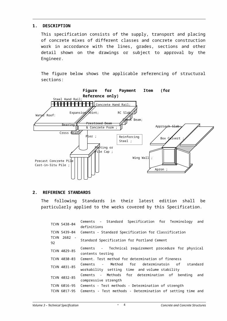
The figure below shows the applicable referencing of structural sections:
2. REFERENCE STANDARDS
The following Standards in their latest edition shall be particularly applied to
the works covered by this Specification.
TCVN 5438-04 Cements - Standard Specification for Terminology and definitions
TCVN 5439-04 Cements - Standard Specification for Classification
TCVN 2682 -
92Standard Specification for Portland Cement
TCVN 4029-85Cements - Technical requirement procedure for physical contents
testing
TCVN 4030-03 Cement. Test method for determination of fineness
TCVN 4031-85Cements - Method for determinatoin of standard workability
setting time and volume stability
TCVN 4032-85Cements - Methods for determination of bending and compressive
strength
TCVN 6016-95 Cements - Test methods - Determination of strength
TCVN 6017-95 Cements - Test methods - Determination of setting time and soundness
AASHTO M6 Fine Aggregate for Portland Cement Concrete; AASHTO M33 Preformed Expansion Joint Filler for Concrete (Bituminous Type)AASHTO M80 Coarse Aggregate for Portland Cement Concrete;
Volume 3 – Technical Specification Concrete and Concrete Structures
Expansion Joint;
Concrete Hand Rail;
RC Slab ;
Prestreed Beam& Concrete Form ;
Apron ;
Wing Wall ;
Footing orPile Cap ;
Pier ; Cross Head ;
Reinforcing Steel ;
Bearing ;
Figure for Payment Item (for Reference only)
Approach Slab:
Cross Beam;
Box Culvert ;
Steel Hand Rail;
Precast Concrete Pile Cast-in-Situ Pile ;
Water Roof:
- 4 -
AASHTO M85 Portland Cement; AASHTO M115 Asphalt for Damp-proofing and Waterproofing; AASHTO M116 Primer for Use With Asphalt in Damp-proofing and
Waterproofing; AASHTO M118 Coal-Tar Pitch for Roofing, Damp-proofing, and Waterproofing; AASHTO M148 Liquid Membrane-Forming Compounds for Curing Concrete; AASHTO M153 Preformed Sponge Rubber and Cork Expansion Joint Fillers for
Concrete Paving and Structural Construction; AASHTO M182 Burlap Cloth made from Jute or Kenaf; AASHTO T22 Compressive Strength of Cylindrical Concrete Specimens; AASHTO T23 Making and Curing Concrete Test Specimens in the Field; AASHTO T96 Resistance to Abrasion of Small Size Coarse Aggregate by Use
of the Los Angeles Machine; AASHTO T119 Slump of Portland Cement Concrete; AASHTO T121 Mass per Cubic Meter, Yield, and Air Content (Gravimetric) of
Concrete; AASHTO T134 Moisture-Density Relations of Soil-Cement Mixtures; AASHTO T141 Sampling Freshly Mixed Concrete; AASHTO T224 Correction for Coarse Particles in the Soil Compaction Test; ASTM C31 Making and Curing Concrete Test Specimens in the Field; ASTM C33 Concrete Aggregates; ASTM C39 Compressive Strength of Cylindrical Concrete Specimens; ASTM C40 Organic Impurities in Fine Aggregates for Concrete; ASTM C87 Effect of Organic Impurities in Fine Aggregate on Strength of
Mortar; ASTM C88 Soundness of Aggregate by Use of Sodium Sulfate or
Magnesium SulfateASTM C91 Masonry Cement; ASTM C94 Standard Specification for Ready-Mixed Concrete; ASTM C109 Compressive Strength of Hydraulic Cement Mortars (Using 2-in.
or 50-mm Cube Specimens); ASTM C123 Lightweight Pieces in Aggregate; ASTM C136 Sieve Analysis of Fine and Coarse Aggregates; ASTM C138 Unit Weight, Yield, and Air Content (Gravimetric) of Concrete; ASTM C143 Slump of Portland Cement Concrete; ASTM C144 Aggregate for Masonry Mortar; ASTM C150 Portland Cement; ASTM C227 Potential Alkali Reactivity of Cement-Aggregate Combinations
(Mortar-Bar Method); ASTM C287 Chemical-Resistant Sulfur Mortar; ASTM C294 Constituents of Natural Mineral Aggregates; ASTM C295 Petrographic Examination of Aggregate for Concrete; ASTM C494 Chemical Admixtures for Concrete; ASTM C827 Change in Height at Early Ages of Cylindrical Specimens of
Cementations Mixtures; ASTM C1017 Chemical Admixtures for Use in Producing Flowing Concrete; ASTM C1077 Laboratories Testing Concrete and Concrete Aggregates for Use
in Construction and Criteria for Laboratory Evaluation.
Volume 3 – Technical Specification Concrete and Concrete Structures- 5 -

3. CONSTRUCTION REQUIREMENTS
3.1 Materials for Concrete
3.1.1 General
(a) The Contractor shall submit samples of all materials to be used in
concrete mixes together with test results confirming their compliance
with this specification for the approval of the Engineer.
(b) The Contractor shall use approved materials to prepare mix designs
and for trial mixes to be approved by the Engineer.
(c) No materials shall be delivered to the Site until materials, mix designs
and trial mixes have been approved by the Engineer.
3.1.2 Portland Cement
(a) Cement shall be Portland cement type I complying in all respects with
ASTM C150 (AASHTO M85). However the Contractor may submit to
the Engineer for his approval fully supported proposals for the use of
other types of cement. All cement shall be manufacturer’s standard
cement unless otherwise specified on the drawings. Only one brand of
cement shall be used for all concrete works throughout the Project
unless otherwise authorized by the Engineer.
(b) The Contractor proposed source of supply of cement shall be
submitted to the Engineer for his approval. All deliveries of cement to
site shall include appropriate test certificates, certified by an
independent agency in the country of origin, confirming that the
material delivered complies with the specification.
(c) Cement shall be delivered to the Site in sealed bags or in bulk.
(c) Bagged cement shall bear the manufacturer’s name, cement type and
the date of manufacture and shall be stored in waterproof sheds or
other such temporary buildings used exclusively for the storage of
cement. Cement shall be stored in dry conditions on areas raised
above ground level. Storage capacity shall be sufficient to hold enough
cement for the largest units to be cast. Bags shall not be stored more
than 8 high and a free passage of at least one meter shall be left
between the cement and the side walls of the sheds.
(d) Cement delivered by bulk carriers shall be stored in silos made for
cement storage. All handling shall be by methods that prevent
contamination of the cement. The silos shall be provided with interior
moisture control devices that keep the cement dry and prevent
premature hydration. The silos shall be provided with access ladders
and access points to enable samples to be taken from various levels of
each silo for testing purposes.
(e) Access ways shall be provided between storage containers such that
every container can be visually inspected. Each delivery shall be
stored separately from previous deliveries. Deliveries shall be used in
Volume 3 – Technical Specification Concrete and Concrete Structures- 6 -

the order in which they were delivered. Any delivery which has become
caked or otherwise adversely affected shall be removed from the Site
at the Contractor’s expense.
(f) The Contractor shall provide weighing machines which shall be kept
permanently in each shed for checking the weight of the bags.
3.1.3 Water for Concrete Mixing and Curing
(a) The Contractor’s proposed water source shall be submitted to the
Engineer for his approval together with test results confirming that
water from the source complies with this specification.
(b) Water for concrete mixes, curing concrete and other products
containing cement shall be clean water free from oil, salt, acid, sugar,
vegetable or any other substance injurious to the concrete unless
otherwise authorized in by the Engineer.
3.1.4 Aggregates
(a) Aggregates shall be free of substances that react deleteriously with
alkali in the cement sufficiently to cause unacceptable expansion of
the concrete. The Engineer’s approval of aggregate sources will be
based on satisfactory evidence furnished by the Contractor that the
aggregate is free from such materials. This evidence shall include
certified records of tests by a testing laboratory that the aggregates
meet the requirements of ASTM-C227 and may include service records
of concrete of comparable properties placed under similar conditions
of exposure. Tests shall be made in accordance with ASTM-C287 and
ASTM-C295 ASTM C1077.
(b) All aggregates shall consist of tough, hard, durable uncoated particles.
The Contractor shall be responsible for processing aggregates to meet
the requirements of this specification. The Contractor’s proposed
sources of aggregates shall be submitted to the Engineer for his
approval. Samples shall be taken in the presence of a representative of
the Engineer and the Contractor for testing and approval before
materials are brought to the Site.
(c) Aggregates shall be stored in stockpiles that ensure the materials
remain free draining and are adequately separated to prevent cross
contamination. Stockpiles shall be placed on a properly prepared
surface to ensure no contamination occurs when materials are re-
handled. Materials shall be handled in a manner which avoids
segregation. All stockpiles are to be labelled with markers indicating
the material type in the stockpile. Materials previously approved but
rendered unacceptable due to inadequate storage or handling will be
rejected. Aggregates shall be stored in sufficient quantity to ensure
that there is no interruption of concreting work at any time.
Aggregates shall be stock near mixing plant, Before mixing aggregates shall be comply enough moisture, aggregates shall
Volume 3 – Technical Specification Concrete and Concrete Structures- 7 -
be checked and approved by the engineer.
(d) Fine and coarse aggregates shall be tested in accordance with the
standards below. Source approval shall be withdrawn if aggregates do
not meet the requirements of this specification during routine testing.
ASTM C39 Compressive Strength
ASTM C40 Organic Impurities
ASTM C87 Mortar Strength
ASTM C88 Soundness
ASTM C123 Coal and Lignite
ASTM C136 Sieve Analysis
(1) Fine Aggregate
(a) Fine aggregate shall consist of natural sand with hard, strong,
durable particles or other inert materials with similar
characteristics. Fine aggregate shall be clean and free from
extraneous materials, clay balls, organic matter or other
detrimental material in accordance with AASHTO M6. The
maximum combined quantity of soluble chloride and sulphate in
fine aggregate shall not exceed 1,000 ppm.
(b) Fine aggregate shall be reasonably graded and shall meet the
grading requirements mentioned in Table 1.
(c) Fine aggregate shall be of such uniformity that the fineness
modulus as defined in AASHTO M6 shall not vary more than 0.20 in
either way from the fineness modulus of the representative
samples used in the mix designs.
Table 1 : Grading Requirements of Fine Aggregate
Sieve Size (mm)
Percent Passing by Weight (%)
9.5 1004.75 95 - 1002.36 80 - 1001.18 50 - 85
0.600 25 - 600.300 5 - 300.150 2 - 10
(2) Coarse Aggregate
(a) Coarse aggregate shall be crushed aggregate and shall be
homogeneous, clean, and free from extraneous materials, clay
lumps, organic matter, and other detrimental materials. Coarse
aggregate shall meet the requirements of AASHTO-M80 and ASTM
C33.
(b) Coarse aggregate shall be reasonably graded and shall meet the
grading requirements in Table-2-1 in subsection 3.2 Concrete
Classes.
Volume 3 – Technical Specification Concrete and Concrete Structures- 8 -
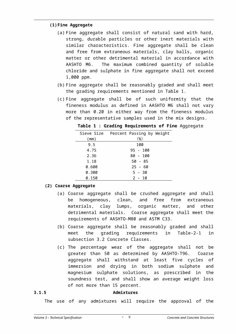
(c) The percentage wear of the aggregate shall not be greater than
50 as determined by AASHTO-T96. Coarse aggregate shall
withstand at least five cycles of immersion and drying in both
sodium sulphate and magnesium sulphate solutions, as
prescribed in the soundness test, and shall show an average
weight loss of not more than 15 percent.
3.1.5 Admixtures
The use of any admixtures will require the approval of the Engineer. Each
type and each location or purpose shall be approved individually. Approval
will be dependent upon the submission of mix designs and satisfactory trial
mixes to demonstrate the function of the admixture.
3.2 Concrete Classes
(a) Concrete shall be of one of the classes shown in Table-2-1. All concrete
classes shall be tested using cylinders in accordance with AASHTO T22
and T23 (ASTM-C39 and C31 respectively).
(b) The strength requirements for each class of concrete as determined by
testing cylinders at 7 and 28 days in accordance with the requirements
of this specification are given in table 2.1 below. The table also includes
other information which is provided as guidance for the Contractor in
determining the contents and properties of his proposed concrete
mixes.
(c) The class of concrete to be used in each part of the Works shall be as
detailed on the drawings subject to confirmation by the Engineer.
However a guide is given in the 2.2 below.
Volume 3 – Technical Specification Concrete and Concrete Structures- 9 -
Table 2.1 Concrete Classes
C50 C35 C30C30(for bored pile)
C25 C20 C10
Minimum Concrete Strength at 28days (150x300mm Cylinder) (Mpa)
50 35 30 30 25 20 10
Maximum Size of Course Aggregate (mm)
20 20 20 20 20 25 40
Minimum Cement Content (kg/m3)
450 380 350 350 330 280 175
Maximum W/C Ratio (%) 30 39.5 45 49.4 50 55 76
Slump (mm) 50-100
50-100
50-100
130-170 50-100
50-100
25-75
Coarse Aggregate
Sieve Size 37.5mm 100 100 100
25.0mm 100 100 100 100 90-100
90-100
95-100
19.0mm 90-100
90-100
90-100
90-100
12.5mm 30-70 30-70 30-70 30-70 25-60 25-60 25-60

Table 2.2 Concrete class - location
Concrete Class LocationClass C50 Precast Girder (Super T)Class C35 CIP Deck Slab (incl Link Slab), Crossbeam of Super TClass C30 Abutment, Pier, Precast Concrete Plank for Super TClass C30 (Bored piles) Bored PileClass C25 Parapet, Pedestal of Lamp Post, Approach SlabClass C20 Sealing ConcreteClass C10 Blinding Concrete
(d) Acceptable ranges for concrete slump shall be determined by
appropriate mix design and subsequent trial mix testing. Slumps shall
be measured in accordance with AASHTO T119.
3.2.1 Approved Mix Design
(a) The Contractor shall submit his proposed mix designs to the Engineer
for his approval and prepare samples in order to Engineer checked and approved samples before carying out mixing concrete on a large scale. The mix design shall include the target mean strength for
the mix and shall be submitted with the results of satisfactory tests
from trial mixes. The mix design and the trial mixes shall use only those
materials that have previously been given source approval by the
Engineer.
(b) No concrete work will be allowed to commence until the Engineer
approves the Contractor’s proposed mix design(s).
(c) A new mix design shall be submitted to the Engineer for his approval if
there are any changes in characteristics or source of supply of any of
the component parts of the mix. Any delay due to such changes shall
be entirely the responsibility of the Contractor.
(d) During the execution of the Works, the Engineer may require additional
tests to be made on the work mix to check compliance with the
approved Mix Design.
3.2.2 Water - Cement Ratio
(a) The Contractor’s proposed water content and water cement ratio shall
be included in the mix designs, supported by trail mixes, submitted to
the Engineer for his approval. The water content shall be the least
amount that shall produce a workable homogeneous plastic mixture.
Excess water shall not be permitted and any batch containing such
excess shall be rejected.
(b) The total water content for any batch of concrete shall include an
allowance for water contained in the aggregates. The Contractor shall
Volume 3 – Technical Specification Concrete and Concrete Structures- 10 -

determine the water content of the aggregates before concrete
batching begins and admixture (if any). The water added to the mix
shall be adjusted for the water contained in the aggregates.
(c) Frequent slump tests shall be carried out to ensure that the workability
of the concrete remains consistent.
3.2.3 Adjustments during Progress of Work
After a mix design has been approved, the mix shall not be changed during
the progress of the work except as follows:
If it is found impossible to obtain concrete of the desired workability with the
mix proportions originally determined, changes in aggregate weights may be
made subject to the approval of the Engineer.
If it is found impossible to produce concrete of the minimum allowable
strength specified, the cement content may be increased subject to the
approval of the Engineer.
3.2.4 Contents of Chloride and Sulphate
(a) The amount of chloride in the concrete mass shall not exceed 1,000
ppm of the total concrete mass, or 6,000 ppm of the amount of cement
in the mix.
(b) The amount of sulphate in the concrete shall not exceed 800 ppm of
the total concrete mass, or 5,000 ppm of the amount of the cement in
the mix.
(c) The amounts of chloride and sulphate shall be determined by
recognized methods of laboratory analyses of the cement, aggregates,
water and admixtures.
3.2.5 Submittals
(a) The Contractor’s submissions shall be made well before the start of any
concrete work on site. The Contractor shall bear in mind the time
required for submitting and gaining the approval of all constituents of
the mix and the time required to prepare mix designs and prove them
by trial mixes and subsequent cylinder tests. The Contractor shall also
allow sufficient time for the Engineer to review the submissions and to
conduct any additional trial mixes and tests that might be necessary.
(b) Each mix design submittal shall include, but not be limited to, the
following:
(a) Project identification;
(b) Name and address of the Contractor and concrete producer;
(c) Mix design designation;
(d) Class of concrete and intended use;
(e) Material proportions;
(f) Name and location of material sources for aggregate, cement,
Volume 3 – Technical Specification Concrete and Concrete Structures- 11 -
admixtures, and water;
(g) Type of cement and type of cement replacement if used. Fly ash, ground iron blast-furnace slag, or silica fume may partially replace cement if complying with pertinent specifications subject to approval by the Engineer.
(h) Cement content in kilogram per cubic meter of concrete;
(i) The saturated surface dry batch mass of the coarse and fine aggregates in kilogram per cubic meter of concrete;
(j) Water content (including free moisture in the aggregate plus water in the drum, exclusive of absorbed moisture in the aggregate) in kilogram per cubic meter of concrete;
(k) Target water/cement ratio;
(l) The water/cement ratio for modified concrete is the ratio of the mass of water to the combined mass of Portland cement and cement substitute;
(m)
Dosage of admixtures;
(n) Sieve analysis of fine and coarse aggregates;
(o) Absorption of fine and coarse aggregates;
(p) Bulk specific gravity (dry and saturated surface dry) of fine and coarse aggregates;
(q) Dry rodded unit mass of coarse aggregate in kilogram per cubic meter;
(r) Fineness modulus (FM) of fine aggregate;
(s) Material certifications for cement, admixtures, and aggregate (if applicable);
(t) Target values for concrete slump with and without high-range water reducers;
(u) Target values for concrete air content (if required);
(v) Concrete unit mass;
(w) Compressive strengths of 7 and 28-day concrete.
3.3 Formwork and Falsework
3.3.1 Design
(a) The Contractor shall submit calculations, shop drawings, working
drawings, and details of all materials and manufactured goods
included in the formwork and falsework to the Engineer for his
approval well before the start of construction work on site. Work shall
not start until approval has been given.
(b) The Contractor shall be solely responsible for the design of the
formwork and its supporting falsework. The design shall include all
necessary strutting, bracing and temporary foundations to ensure the
support of all temporary works items, equipment, the weight of the
plastic concrete or any other loading resulting from methods adopted
for the placing and compaction of the concrete or any incidental
Volume 3 – Technical Specification Concrete and Concrete Structures- 12 -

loading. There shall be no harmful deformation of the forms during
the concreting operation. No accessory for supporting the formwork or
staging shall be built into the permanent structure except with the
Engineer’s approval.
(c) The design shall be appropriate for such temporary works and shall take into full consideration all temporary loading cases arising from the procedures and work sequences, the prevailing conditions at the site, in particular likely wind loading, and the nature of the existing ground. The Contractor shall carry out all additional soils investigation necessary to confirm his assumptions concerning the nature of the existing ground.
(d) Formwork and falsework shall be designed for vertical load and lateral
pressures in accordance with ACI 347 and, where appropriate, any
increased or re-adjusted loading that may result from pre-stressing
forces. If retarding admixtures are used, their effect shall be duly
considered during the calculation of the lateral pressures of the fresh
concrete. The formwork and falsework shall be designed and
constructed to ensure completed concrete surfaces comply with the
tolerances specified in ACI 347 or elsewhere in this specification.
(e) The shop drawings and working drawings shall show the proposed
details of construction of members, spacing of bents, posts, studs,
walings, stringers, collars, bolts, wedges, bracing, rate of pour, and
the manufacturer’s recommended safe working capacity of all form
ties and column clasps. All assumptions, dimensions, material
properties and other data used in the structural analysis shall be
noted on the shop drawings. The Contractor shall furnish copies of
the design calculations to the Engineer for his consideration when
approving the Contractor’s proposals.
(f) The calculations and drawings shall be certified and stamped by a qualified structural engineer experienced in the preparation of such designs.
(g) When manufactured formwork, shoring or scaffolding units are used,
the manufacturer’s recommendations for allowable loads shall be
followed. In such cases the Contractor shall provide certificates and
test reports or records of successful experience. Reduced allowable
load values may be required for materials which have or will
experience substantial reuse.
(h) Where falsework openings are required for maintaining traffic flows or
for pedestrian access the Contractor shall provide all necessary
additional features to protect the public and to ensure that the
falsework will remain stable, particularly if subject to impact by a
vehicle. Where openings are provide the design shall include but not
be limited to
(i) the anchoring of stringers to caps or frames in adjacent spans.
(ii) adequate bracing during construction or removal, and
Volume 3 – Technical Specification Concrete and Concrete Structures- 13 -

(iii) at least a 300mm. gap between the falsework and protective
railing.
3.3.2 Construction of Formwork
(a) The formwork shall be constructed accurately to represent the shape
of the structure as detailed on the drawings. It shall be of suitable
design and appropriate construction and shall have been approved by
the Engineer. The Contractor shall make any necessary adjustments
to allow for shrinkage, settlement or deflection which may occur
during construction so that the finished concrete sections conform
accurately to the specified dimensions true to line, level, location and
camber.
(b) Wooden boards shall be cut accurately to shape and fixed such that
there are no openings after the wetting of the formwork prior to
placing concrete.
(c) Unless otherwise required by the Engineer concrete class C10 shall be
placed to a minimum depth of 10 cm in the footing of foundations to
structures to provide a working platform and to ensure stability of the
foundation soils. The concrete area shall be sufficient to provide
support for the Contractor’s proposed formwork.
(d) All formwork surfaces shall be fabricated to comply with the
requirements of clause 3.6 of this specification unless otherwise
required by the drawings or other Specification Sections. Surfaces
which are completely enclosed or hidden below the permanent
surfaces of the ground or surfaces with no specified finish may be
formed of sawn boards or similar material. Any lumber or material
which is damaged or warped prior to placing of the concrete shall be
rejected. All exposed surfaces shall be formed using plywood or
metal formwork. The surfaces of plywood or metal formwork shall be
kept clean and in good condition at all times to ensure that all
concrete surfaces have a consistent appearance that complies with
this specification. The Engineer will reject formwork that does not
comply with this specification and rejected formwork shall be removed
from site.
(f) All exposed sharp edges shall be chamfered using triangular fillets not
less than 2 cm by 2 cm in size, unless otherwise directed by the
Engineer. The triangular fillets or chamfer strips shall be milled from
clear, straight grain lumber and shall have a finished surfaced on all
sides. Curved surfaces shall be formed of plywood, metal, or other
suitable material.
(g) All formwork and falsework shall be constructed using stiff walings
(separators) fixed at right angles to studs. Walings shall be paired and
tied together by ties or clamps which pass through the formwork.
Bolts, ties and form clamps to hold formwork together shall be
Volume 3 – Technical Specification Concrete and Concrete Structures- 14 -

positive in action and shall have sufficient strength and be sufficient
in number to prevent spreading of the forms. Lifting anchors may be
installed in pre-cast members. Bolts, ties, form clamps and lifting
anchors shall be entirely removed or cut back, leaving no metal within
3 cm from the concrete surface.
(i) Drainage holes and weep holes shall be constructed as detailed on
the drawings. Forms for weep holes shall be approved by the
Engineer.
(j) The Contractor shall ensure that all required inserts, anchors,
expansion joint and bearing elements, sleeves, and other items in this
specification are installed in the formwork. The Contractor shall
coordinate the installation with other trades to ensure proper location
of such items. Ends of piping and sleeves embedded in concrete shall
be closed with caps or plugs.
(k) No concrete shall be placed in the formwork until construction of the
formwork and falsework, the provision and fixing of reinforcement, the
provision of ducts, anchorages, and pre-stressing steel and the
provision and fixing of all inserts, anchors and expansion joint and
bearing elements has been completed for the unit and the unit has
been cleaned and sealed to prevent grout leaks all to the satisfaction
of the Engineer.
(l) With the exception of permanent formwork, all formwork surfaces
which shall have concrete against them shall be treated with a release
agent which shall be subject to the approval of the Engineer. Release
agents shall be applied strictly in accordance with the manufacturer’s
instructions and shall not come into contact with the reinforcement or
prestressing tendons and anchorages. Different release agents shall
not be used in formwork for concrete that will be visible in the finished
Works. Forms shall be saturated with water before concrete is placed.
The surfaces of formwork shall be free from any material that shall
adhere to or discolour the concrete and all materials applied to the
surfaces shall be non-staining.
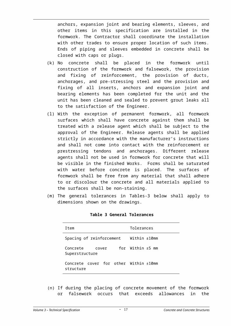
(m) The general tolerances in Tables-3 below shall apply to dimensions
shown on the drawings.
Table 3 General Tolerances
Item Tolerances
Spacing of reinforcement Within ±10mm
Concrete cover for Superstructure
Within ±5 mm
Volume 3 – Technical Specification Concrete and Concrete Structures- 15 -

Concrete cover for other structure
Within ±10mm
(n) If during the placing of concrete movement of the formwork or falsework occurs that exceeds allowances in the Contractor’s design or will result in completed work unacceptably out of tolerance, then placing of concrete shall stop. Placing of concrete shall not re-start until such time as corrective measures satisfactory to the Engineer have been taken by the Contractor. If such measures are not taken before the initial set of the concrete placing of concrete shall not be permitted to re-start. In such case a joint shall be formed and all unacceptable concrete removed all to the satisfaction of the Engineer.
3.3.3 Removal of falsework and formwork
(a) Concrete shall have reached the strengths indicated in Table 4 below
before the removal of formwork and false-work. No formwork or
falsework shall be removed without the approval of the Engineer.
Table 4 Removable Time of Form/False work
Formwork/Falsework Time / % of Design Strength of Concrete
Pre-tensioned T beams - / 85%
Support members/Pier head (30 MPa) - / 100%
Centring under girders, beams, frames or arches.
14 days / 80%
Floor slabs 14 days / 70%
Columns 2 days / 70%
Walls, sides of beams and all other vertical surfaces
1 day / 70%
To enable finishing, forms used for parapets, barriers, and exposed vertical surfaces shall be removed between 24 hours and 48 hours after casting, depending on
weather conditions.
(b) In continuous structures, falsework for a particular span shall not be
released until adjoining spans which will be subject to loading as a result of such release have reached their specified strengths. Falsework or formwork for all spans which affect the loading of a particular span shall be released before concrete is placed in railings, parapets or other elements for the particular span. Release of falsework and formwork for continuous spans or cantilevers shall be carried to ensure a gradual application of working stresses.
(c) Where appropriate formwork to columns shall be removed before the removal of formwork and falsework to beams and girders to ensure the columns are satisfactory.
(d) At the discretion of the Contractor and subject to the approval of the Engineer, formwork and falsework may be left in place for footings
Volume 3 – Technical Specification Concrete and Concrete Structures- 16 -
within coffer dams or crib work should the removal endanger the safety of the coffer dams or cribs, provided that such forms are not visible in the finished structure. All other fromwork or falsework both above and below water level shall be removed.
3.4 Concreting
3.4.1 General
(a) No concrete shall be placed until the formwork and falsework has
been completed in accordance with clause 3.3.2 above and approved
by the Engineer. No concrete shall be placed without the approval of
the Engineer.
(b) Concrete may be mixed at the site of construction, at a central point,
by a combination of central point and truck mixing or by a
combination of central point mixing and truck agitating.
(c) All concrete shall be batched by weight unless otherwise directed by
the Engineer. The weight-batching machines shall be of a type
approved by the Engineer and shall be kept calibrated, accurate and
in good condition. Checks shall be made as required by the Engineer
to determine that the weighing devices are registering correctly. Each
mixer shall be fitted with a water measuring device having accuracy
within one percent of the quantity of water required for the batch.
The measuring device shall be such that its accuracy is not affected
by variations in the water supply pressure.
(d) Where aggregate batching by volume is permitted, each size of
aggregate shall be measured in a metallic container, the depth of
which shall be at least equal to its greatest width. The containers
shall be of such shape that their volume can be easily checked by
measurement. Cement shall be batched by weight and water by
weight or volume.
(e) The batching of concrete shall not begin until such time as all the
equipment and labour required for batching, transporting, placing,
compacting, finishing and curing the concrete is in place in
accordance with the Contractor’s approved method statement.
3.4.2 Batching
(a) Measurement and batching of materials shall be done at a batching
plant and all concrete shall be machine mixed.
(b) The Contractor shall submit his method statement for the batching
and mixing of concrete to the Engineer for his approval. The
statement shall include the location of the batching and mixing plant,
the type or types of mixers and machines to be used, arrangements
for the storage of aggregates and the batching and mixing of concrete
and transporting concrete from the batching plant to the site.
(c) The type of mixer shall be a drum mixer. Mixers of less than 0.5 cubic
meter capacity shall not be used to batch structural concrete. The
Volume 3 – Technical Specification Concrete and Concrete Structures- 17 -

use of continuous mixers will not be permitted.
(d) The batching plant shall include separate bins for the bulk cement,
fine aggregate and for each size of coarse aggregate, a weighing
hopper, and scales capable of determining accurately the weight of
each component of the batch. Scales shall be accurate to one percent
throughout the range of use.
(f) If there is no prior experience with the approved mix design or if
special handling procedures, such as pumping, change of one or more
of the characteristics between discharge of the load and placing in the
forms, the Contractor shall correlate the discharge tests with the
placement tests to define these changes.
(g) The Contractor shall also provide documentation, repeat the
correlations as often as necessary or as directed by The Engineer.
(1) Portland Cement
(a) Either sacked or bulk cement may be used. No fraction of a sack of
cement shall be used in a batch of concrete.
(b) All bulk cement shall be weighed on an approved weighing device.
The bulk cement weighing hopper shall be properly sealed and
vented to prevent the escape of cement dust. The discharge chute
shall not be suspended from the weighing hopper and shall be so
arranged that cement will not lodge in it nor leak from it.
(c) Accuracy of batching shall be within 1 percent of the required
weight.
(2) Water
(a) Water may be measured either by volume or by weight. The
accuracy of water measurement shall be within one percent of the
required weight or volume.
(b) About 10 percent of the water required for the batch shall be
poured into the drum before the cement and aggregates, and the
remainder of the water shall be added uniformly while the drum is
in action and all the water shall be in the drum by the end of the
first quarter of the mixing time.
(3) Aggregates
(a) All aggregates produced or handled by hydraulic methods or that
have been washed shall be stockpiled or binned for draining at
least 12 hours before being batched. Where the moisture content
of aggregates is high or non-uniform, they shall be stored or
stockpiled for a period in excess of 12 subject to approval by the
Engineer.
(b) The accuracy of measurement of aggregates shall be within two
percent of the required weights.
Volume 3 – Technical Specification Concrete and Concrete Structures- 18 -
3.4.3 Mixing and Delivery
(a) When mixed batches are hauled to the mixer, bulk cement shall be
transported either in waterproof compartments or between the fine
and coarse aggregates. Where cement is placed in contact with moist
aggregates, batches will be rejected unless mixed within 1.5 hours of
such contact. Bagged cement may be transported on top of the
aggregates.
(b) The concrete shall be mixed until a uniform colour and consistency is
obtained.
(c) Mixing and delivery of concrete shall be in accordance with the
requirements of ASTM C94 except where modified in this specification
for truck mixing or a combination of central point and truck mixing or
truck agitating. Delivery of concrete shall be so regulated that
placing is at a continuous rate unless delayed by the placing
operations. The intervals between deliveries of batches shall not be
so great as to allow the concrete in place to harden partially, and in
no case shall such an interval exceed 45 minutes.
(d) Any arrangements for the cooling of the mixing water as and the
handling of admixtures shall be subject to approval by the Engineer.
(e) Additional mixing water and/or admixture may not be added on the
Work Site unless specifically authorized by the Engineer and if the
water/cement ratio in the approved job mix is not exceeded and the
truck mixer is loaded to no more than 70 percent of its rated
capacity.
(f) The volume of concrete mixed per batch shall not exceed the mixer’s
nominal capacity as shown on the manufacturer’s standard rating
plate on the mixer. Water shall be added as required by clause 3.4.2
(2)b above.
(g) Mixing shall continue for the minimum times shown below after all the
water has been added.
mixers having a capacity of 1.5
m3 or less
minimum 60
seconds
mixers having a capacity greater
than 1.5 m3
minimum 90
seconds
mixer with a capacity of 750
liters or less
minimum 1.5
minutes
each additional 500 liter
capacity or fraction
be increased by
15 seconds
double-drum high performance
mixer
minimum 70
seconds
Volume 3 – Technical Specification Concrete and Concrete Structures- 19 -
(h) Mixing time shall be measured from the time all materials, except
water, are in the drum.
(i) The timing device on stationary mixers shall be equipped with a bell
or other suitable warning device to give a clearly audible signal each
time the lock is released. If the timing device fails, the Contractor
may continue operations for up to 24 hours while it is being repaired,
provided he furnishes an approved timepiece equipped with minute
and second hands. After 24 hours the mixer shall not be used until
repairs are made.
(j) On cessation of work, including all stoppages exceeding 20 minutes,
the mixers and all handling plant shall be washed with clean water.
Any deposits of old concrete in the drum shall be cleaned out by
rotating clean aggregate and water in the drum before any fresh
concrete is mixed.
(k) Concrete that is not in place within one hour of the time when
ingredients were charged into the mixing drum, or concrete that has
developed an initial set, shall be rejected.
3.4.4 Concrete Consistency
The concrete slump shall be determined by the Contractor’s trial mixes and
shall be measured in accordance with AASHTO T119.
3.4.5 Pumping
(a) Placing of concrete by pump subject to the approval of the Engineer.
(b) Where concrete is conveyed and placed by pump, the equipment shall
be fit for purpose and of sufficient capacity for the work.
(c) The operation of the pump shall produce a continuous stream of
concrete without air pockets.
(d) When pumping is completed, If the concrete remaining in the pipeline
after completion of placing is to be used, it shall be ejected in such a
manner that there shall be no contamination of the concrete or
separation of the ingredients.
3.4.6 Placing and Compacting
(a) The Contractor shall include the method and sequence of placing
concrete in his method statement to be approved by the Engineer.
Concrete shall not be placed until formwork and reinforcement have
been approved by the Engineer has.
(b) Concrete shall be placed gently in position and shall not have a free
fall of more than 1.5m to avoid segregation of the materials and
displacement of the reinforcement.
(c) The use of pipes or chutes for transporting concrete shall not be
permitted without the approval of the Engineer.
(d) Where the use of pipes or chutes is permitted they shall be rubber or
Volume 3 – Technical Specification Concrete and Concrete Structures- 20 -

metal. Where steep slopes are required chutes shall be equipped with
baffle boards or be in short lengths that reverse the direction of
movement. The use of aluminium chutes, tremie pipes, troughs, and
pipes will not be permitted.
(e) Pipes or chutes may be allowed for small sections and bottom dump
buckets or other suitable vessels may be allowed for large sections to
convey the concrete as near as possible to its final position.
(g) Concrete shall be placed so as to prevent water from collecting at the
ends, corners or along the faces of the forms, and water shall not be
placed in large quantities at a given point and allowed to run or be
worked over a long distance in the form.
(h) All concrete shall be placed and compacted in even layers with each
batch and each layer merged with the previous one.
(i) The thickness of concrete layers shall be between 15-cm and 30-cm
for reinforced concrete and up to 45 cm for none reinforced concrete.
(j) Concrete shall be compacted by mechanical or electromechanical
poker vibrators. Each immersion shall continue until shortly after air
bubbles cease to appear on the surface of the concrete, but shall not
last more than 30 seconds. Vibrators shall be withdrawn gradually
and vertically to ensure that no air pockets are formed. Over-vibration
of concrete will not be permitted. Vibrators shall not be in contact
with reinforcement in any circumstances. Vibrators shall not be used
to distribute concrete in the formwork.
(k) When required, vibrating shall be supplemented by hand spading with
suitable tools to assure proper and adequate compaction
(l) The Contractor shall provide stand-by vibrators during all concrete
pours. At least two vibrators shall be available at the site when more
than 25 m3 of concrete are to be placed.
(m) All vibration, compaction and finishing operations shall be completed
immediately after the placing of concrete in its final position.
(n) Concreting in any one part or section of the work shall be carried out
in one continuous operation and no interruption of work will be
allowed.
(o) Where beams and slabs together form an integral part of the
structure, they shall be poured in one operation, unless otherwise
specified or an approved provision is made to form a construction
joint.
(p) After a beam, wall or column has been cast, an interval of one hour
shall be allowed before casting the continuous slab. The same applies
for all abrupt changes in sections.
(q) During placing exposed concrete surfaces shall be worked by means
of tools of an approved type to force all coarse aggregate from the
Volume 3 – Technical Specification Concrete and Concrete Structures- 21 -

surface, to bring mortar against the forms to produce a smooth finish,
substantially free from water and air pockets, or honeycombing.
Excessive working which produces layers of laitance on the surface
will not be permitted.
(r) Freshly placed concrete shall be adequately protected from rain, dust
storms, chemical attack and the harmful effects of sun, heat, wind,
flowing water, vibrations and shocks. It shall also be fenced off or
otherwise protected to prevent persons from walking thereon or
articles being placed or thrown thereon. This protection shall
continue until the concrete is sufficiently set such that it can no longer
be damaged by these factors. The protection shall not be less than 24
hours after the time of placing subject to the approval of the Engineer.
(s) The Contractor shall take all necessary precautions to prevent
differential temperatures across any concrete element from exceeding
20oC during concrete placing and curing.
3.4.7 Placing of Concrete in or Under Water
(a) The Contractor shall submit his proposed methods for placing
concrete in or under water to the Engineer for his approval before
proceeding with the work.
(b) The method of placing concrete in or under water shall be such as to
keep as much as possible the concrete being placed out of direct
contact with the water to avoid any rapid movement or agitation of
the exposed concrete surface.
(d) Tremie pipes shall be smooth bored, watertight, fitted with quick
release joints and have an adequate cross-section for the size of
aggregate to be used. Aluminium pipes shall not be used.
(e) Bottom opening skips shall be straight sided, smooth and fitted with
externally operated bottom opening double doors and overlapping
canvas flaps.
(g) Where concrete is to be placed in or under water, the actual mix
proportions and selection of aggregates shall be such as to ensure a
resulting concrete with good flow and cohesion characteristics.
(h) The cement content shall be 25 percent greater than for a
comparable mix for use in dry conditions. The minimum cylinder
strength for all concrete shall be approved by the Engineer for the
comparable mixes for use in dry conditions.
3.4.8 Weather Precautions
(a) During hot weather steps shall be taken to reduce the concrete
temperature. When the air temperature in the shade is 35oC and
rising, precautions shall be taken during all concrete operations so
that the temperature of the concrete when placed does not exceed
32oC.
Volume 3 – Technical Specification Concrete and Concrete Structures- 22 -

(b) The concrete mixing plant shall be screened and covered to protect it
from the sun (and wind and rain). Similar precautions shall be taken
throughout the transit, placing and curing of the concrete whenever
conditions require them.
(c) Aggregates shall be shaded and mixing water shall be cooled and
other steps taken to the satisfaction of the Engineer.
(d) Fresh concrete placed at air temperatures of 35oC or higher shall be
shaded from the direct rays of the sun to the satisfaction of the
Engineer.
3.4.9 Continuity of Concrete Work
(a) The Contractor shall carry out the work in such a manner that the
placing of concrete in any particular section of the structure shall be
executed without any interruption whatsoever from the beginning to
the end of the operation. If interruptions occur, no fresh concrete
shall be deposited on or against the concrete placed before the
interruption such time as the concrete is sufficiently set to permit the
formation of a construction joint.
(b) Particular care shall be taken to ensure that partially set concrete
shall not be damaged by shock or any other cause whatsoever.
(c) To ensure continuity casting of concrete shall not commence until
sufficient approved material is at hand to ensure completion of the
operation and there is sufficient equipment in reserve for use in the
case of breakdown.
3.5 Joints
3.5.1 General
(a) Joints shall be limited to the positions indicated on the drawings and
shall be of the type specified.
(b) Expansion joints shall incorporate in their construction adequate
protection against the entry of debris or other material that may
interfere with the closing of the joints.
(c) Construction joints are detailed on the drawings which shall as a rule
be formed at right angles to the axis of the members.
3.5.2 Construction Joints
(a) Construction joints shall be made only at locations indicated on the
drawings or as specified herein, except in cases of breakdowns or
other unforeseen and unavoidable delays, in which case the a joint
shall be formed to the satisfaction of the Engineer.
(b) Construction joints in abutment walls, wing-walls, and barrels of box
culverts shall not be placed at intervals exceeding 10 meters except
as otherwise indicated on the drawings or as may be approved by the
Engineer.
Volume 3 – Technical Specification Concrete and Concrete Structures- 23 -

(c) All joints which are exposed to view shall be carefully finished true to
line and elevation. After the header board has been removed, laitance
shall be removed from the surface by washing with water under
pressure or by sandblasting to expose clean, well bonded aggregate.
After the surface has been prepared, the concrete shall be left
saturated with water until the new concrete is placed, or it shall be
saturated for a period of 4 hours before placing the new concrete.
Shear keys or steel dowels shall be used where required. Shear keys
formed into the concrete shall be formed by the insertion and
subsequent removal of bevelled wood strips which shall be thoroughly
saturated with water prior to insertion. The size and spacing of the
keys and dowels shall be subject to approval by the Engineer.
(d) Care shall be exercised not to injure the concrete or break the
concrete-steel bond at any time. On bridge slabs workmen shall not
be permitted to stand or walk on the reinforcement until the concrete
has hardened. Suitable boards or platforms supported on the slab
formwork shall be provided for access during casting.
3.5.3 Bonded Construction Joints
Except where otherwise specified, bonded construction joints shall be
made using any of the following procedures, as appropriate.
(a) After the header board has been removed, laitance shall be removed
from the surface by washing with water under pressure or by
sandblasting to expose clean, well bonded aggregate. When the
concrete has been cured for the normal period, the second pour shall
be bonded to the first pour by the application of a two-component
liquid polysulphide polymer epoxy resin concrete adhesive to the
concrete joint surface. The epoxy concrete adhesive shall be subject
to approval by the Engineer.
(b) The surface on which the adhesive is to be applied shall be free of oil,
dirt, and loose concrete. All unsound concrete shall be removed until
a base of strong, undamaged concrete on which to apply the adhesive
is exposed. Heavy deposits of dirt or oil products shall be removed by
wire brushing or sandblasting. The surface shall be free of moisture
and dry before application of the adhesive.
(c) Immediately before application, the two adhesive components shall
be combined in the proportions and to the methods specified by the
manufacturer. All components shall be fully blended. The amount of
adhesive mixed at one time shall be limited to that quantity which can
be conveniently applied within the pot life indicated by the
manufacturer.
d) The resulting adhesive shall be applied to the concrete in accordance
with the manufacturer’s recommendations. Concrete shall not be
placed against the joint until the adhesive has become tacky or
Volume 3 – Technical Specification Concrete and Concrete Structures- 24 -

otherwise recommended by the manufacturer. Areas that have been
allowed to dry shall be recoated before concrete is placed.
(e) Adhesives may be toxic or otherwise injurious to health or otherwise
be classified as hazardous materials. The Contractor shall obtain from
the manufacturers of the materials complete instructions as to the
health and safety precautions that must be exercised with respect to
the materials to be used, and as to the procedure that shall be
followed in the event that workmen come in contact with such
materials. Before they are permitted to proceed with the work,
workmen shall be instructed on the hazards to which they will be
exposed, the necessary safety precautions and the procedure to be
followed in the event of accidental contact with the materials.
3.5.4 Joint between the deck slab and the coping.
The joint between the deck slab and the coping shall be de-bonded using an approved elastic material which shall allow movement between the slab and the coping. The Contractor shall submit his proposal for the provision and placing of the de-bonding layer to the Engineer for his approval.
3.6 Concrete Finishing
3.6.1 Finishing Concrete Surfaces
All concrete surfaces shall be finished as indicated on the drawings or as
otherwise approved by the Engineer.
(a) Permanently exposed concrete surfaces to Class F4, F3 and F2 finish
shall be protected from rust marks and stains of all kinds.
(b) Unless otherwise described in the Specifications, all formwork joints for
exposed surfaces of concrete to Class F2, F3 and F4 finish shall form a
regular pattern with horizontal and vertical lines continuous
throughout each structure and all construction joints shall coincide
with these horizontal or vertical lines.
(c) The types of surface finishes and necessary form works are as follows:
Table 5:Type of Concrete Finishes
Finishing Description Formworks
Formed Finish
Class F1No particular requirements for finishing
Sawn Formwork for unexposed concrete surfaces
Class F2With specified regularities on the finish
Wrought Formwork of steel or plywood or timber.
Class F3
With accurate finishing to provide a smooth finish of uniform texture and appearance
Lined Formwork using material approved by the Engineer to be of the same type and obtained from one source throughout for any one structure.
Class F4With accurate finishing on the use of internal ties and embedded metal parts
Unformed Finish
Class U1 Leveled by wooden float etc. -Class U2 Steel float finishing
Volume 3 – Technical Specification Concrete and Concrete Structures- 25 -

Class U3 Finishing by steel-trowel 3.6.2 Remedial Treatment of Finished Surfaces
(a) Any remedial treatment to finished surfaces shall be agreed with the
Engineer following inspection immediately after removing the
formwork and shall be carried out without delay.
(b) Any concrete the surface of which has been treated before being
inspected by the Engineer will be liable to rejection.
3.6.3 Fixing of Ironwork
All brackets, lag-bolts and other ironwork for which holes have been boxed
out or left in the concrete of a structure shall be carefully grouted into their
correct positions. 3.6.4 Reconstruction of Faulty Work
In the event any members or portion of the work proves, after removal of
the formwork, to be of inferior workmanship or to be in any way
whatsoever defective, or should crushing tests on samples taken from the
work show that the concrete used therein is of inferior Quality, such work
shall, at the discretion of the Engineer, be cut out and replaced.
3.7 Curing
(a) All newly placed concrete shall be cured. Curing shall begin
immediately after finishing and continue for at least 7 days. Curing is
required to prevent drying out of the concrete and shall be considered
an integral part of the concreting operations.
(b) Improperly cured concrete will be considered defective. Concrete work
will not be permitted to continue until proper procedures are put into
effect by the Contractor.
(c) Curing of concrete shall be included in the Contractor’s method
statement and shall be subject to the approval of the Engineer. The
methods detailed below may be used.
(c) Timber formwork covering the concrete shall be moistened with water
at frequent intervals to keep it from drying during the curing period.
Metal formwork exposed to the sun must be shaded from its direct rays,
painted white or otherwise protected during the curing period.
(d) When forms are removed before the end of the 7-day curing period,
specified curing procedures shall be applied by the Contractor and
continued until the end of the 7-day period as specified.
3.7.1 Methods using water
Surfaces may be kept moist by ponding, sprinkling, or fogging. Coverings
such as burlap shall be used to retain water so supplied. The use of
sawdust will not be allowed and coverings that cause unsightly
discoloration of concrete shall not be used. Any method that results in the
concrete being alternately wet and dry will be considered an improper
Volume 3 – Technical Specification Concrete and Concrete Structures- 26 -
curing procedure. Coverings shall be placed as soon as possible after
finishing operations have been completed and there is no danger of
surface damage. The coverings shall be kept continuously moist. 3.7.2 Preventing Moisture Loss
Moisture loss may be prevented by the use of approved waterproof paper,
plastic sheets, or liquid membrane curing compound except where other
requirements prohibit the use of these compounds. If a formed surface is
to be rubbed, the concrete shall be kept moist before and during the
rubbing, and the curing shall be initiated immediately following the first
rub while the concrete surface is still moist. 3.7.3 Waterproof Paper
The paper shall have the widest practicable width and adjacent sheets
shall overlap a minimum of 15 cm and shall be tightly sealed with a
pressure sensitive tape, mastic, glue or other approved methods to form a
complete waterproof cover of the entire concrete surface. The paper shall
be secured so as not to be displaced by wind. If any portion of the sheets
is broken or damaged before expiration of the curing period, the broken or
damaged portion shall be immediately repaired. Sections that have lost
their waterproof qualities shall not be used. 3.7.4 Plastic Sheets
The sheets shall be used in the same manner as required above for
waterproof paper. 3.7.5 Curing Compounds
(a) Curing compounds shall not be used on areas receiving a rubbed
finish. Only Type 2 liquid membrane curing compound complying with
AASHTO M148 may be used subject to approval by the Engineer.
Curing compounds shall be applied to unformed areas as soon as the
water sheen has practically disappeared from the concrete, or as soon
as the forms have been removed from surfaces. If there is any
expected delay in applying curing compound, the surface shall
receive moist curing until the compound can be applied.
(b) All curing compounds shall be thoroughly agitated just prior to use
and shall be applied with equipment that will produce a fine spray.
The compound shall be applied in two coats sprayed at right angles to
each other. The rate of each application shall be not less than 1 liter
for each 3.6 square meters of surface or as detailed in the
manufacturer’s information.
(c) Care shall be taken to prevent application to surfaces where a
concrete bond is required, and to joints where joint sealer is to be
placed. If the membrane film is broken or damaged at any time
during the curing period, the broken or damaged area(s) shall be re-
coated according to the original requirements.
Volume 3 – Technical Specification Concrete and Concrete Structures- 27 -
3.8 Precast Concrete
(a) Pre-cast concrete elements shall be provided as detailed in the
drawings.
(b) The Contractor shall provide and install all pre-cast elements complete,
furnishing all materials, labour and equipment and performing all
required work as required by drawings, as specified herein, other
applicable Specification Sections and as may be required by the
Engineer.
(c) The pre-cast constituents and component work shall include, but not be
limited to, the supply and installation of the pre-cast elements,
necessary grout and grouting and all appurtenances required for their
proper installation.
3.8.1 Materials
(a) Concrete materials incorporated in the fabrication of pre-cast elements
shall comply with the applicable requirements of this section of the
specification as well as other applicable Specification Sections and shall
be of the class of concrete as noted on the drawings or as may be
required by the Engineer.
(b) Grout shall be an approved, free flowing, non-shrink, non-metallic grout
containing sulphate resistant cement. The grout shall have a minimum
28 day compressive strength of 20 MPa when tested in accordance with
appropriate sections of ASTM C109. The grout shall show no expansion
after the final set takes place when tested in accordance with ASTM
C827 or an equivalent test method that may be approved by the
Engineer. The grout shall have an initial setting time of not less than 45
minutes.
3.8.2 Fabrication
(a) T girders shall be cast horizontally.
(b) The dimensional length of beams shown on the drawings is the required
length including allowances for elastic shortening creep or shrinkage.
(d) To ensure proper bond to the deck slab, the top surface of girders in
contact with deck slabs shall be given a rough exposed aggregate
finish. At approximately the time of initial set, all laitance shall be
removed with a coarse wire to expose the concrete aggregate.
(e) Pre-cast elements that are manufactured off-site shall not be
transported from the fabrication area until the concrete has achieved
its 28 day strength.
(f) All pre-cast members shall be lifted and supported only at the points
indicated on the drawings or as may be otherwise approved by the
Engineer.
(g) Pre-cast items shall be lifted and handled to in such a way that no
damage occurs. Any damage to pre-cast items that occurs during
Volume 3 – Technical Specification Concrete and Concrete Structures- 28 -

transportation or placement shall be inspected by the Engineer. The
Engineer may reject damaged pre-cast items if, in his opinion, such
damage will adversely affect the strength or the appearance of pre-cast
items.
3.9 Quality Control of Concrete
3.9.1 General
(a) The quality control of concrete shall be included in the Contractor’s
Quality Assurance scheme for the entire Project. The Contractor shall
make particular reference to the target mean strength of the concrete
in his quality scheme and shall describe clearly all factors relevant to
its determination.
(b) All Quality control tests must be carried out in a manner acceptable to
the Engineer and shall be conducted by an Independent Laboratory or
the Contractor’s laboratory on Site.
3.9.2 Technicians at Mixing Plant
(a) The Contractor shall designate a competent and experienced concrete
technician to be in charge of the mixing plant and to be responsible
for quality control including, but not limited to, the following:
(i) The proper storage and handling of all components of the mix.
(ii) The proper maintenance and cleanliness of plant, trucks, and other equipment.
(iii) The gradation testing of fine and coarse aggregates.
(iv)
The determination of the fineness modulus of fine aggregate.
(v) The measurement of moisture content of the aggregates and adjustment of the mix proportions as required before each day's production or more often if necessary to maintain the required water/cement ratio.
(vi)
The computation of the batch masses for each day's production and the checking of the plant's calibration as necessary.
(b) He shall be assisted by at least one competent and experienced
concrete technician at the project site responsible for concrete
sampling and testing during placing of concrete.
(c) He shall ensure furnishing on behalf of the Contractor of all equipment
and the performance of temperature, unit mass, slump, and other
tests to verify compliance with the specification before and during
each placement operation.
(d) He shall verify that adjustments to the mix before discharge comply
with the specifications.
(e) He shall ensure completion of the batch ticket, which shall include the
detail below, the recording of the apparent water/cement ratio, and
the time discharge are completed; furnishing a copy of each batch
ticket at the time of placement.
Volume 3 – Technical Specification Concrete and Concrete Structures- 29 -

Concrete supplier
Ticket serial number
Date and truck number
Contractor
Structure or location of placement
Mix-design and concrete class
Component quantities and concrete total volume
Moisture corrections for aggregate moisture
Total water in mix at plant
Time of batching
Time at which discharge must be completed
(g) Ensure testing to determine the unit mass, slump, and temperature
according to this specification.
(h) The provision of copies of work sheets and test results as they are
completed.
3.9.3 Sampling of Mixed Concrete
(a) The frequency of sampling and testing shall be included in the quality
control plan for concrete and subject to the approval of the Engineer.
(b) Samples shall be taken from each work item or batch as in the
Contractor ‘s approved quality control plan and in accordance with
AASHTO-T141. The temperature and slump of the concrete shall be
tested for each load at discharge or at such frequency as may be
approved by the Engineer. Test will not be deemed to have been
carried out unless witnessed by the Engineer or his representative.
The method of making the slump test shall conform to ASTM C143.
(c) Sampling at discharge shall be after at least 0.2 cubic meters are
discharged and before placing any of the batch in the forms.
(d) The initial testing frequency shall be resumed if a test shows a failing
temperature or slump or when required by the Engineer.
(e) The Contractor shall bear all expenses for obtaining, cutting out or
sampling all specimens and/or component parts for testing.
3.9.4 Compressive Strength Testing
(a) Testing to determine the compressive strength of concrete shall be
used for the following purposes:
* to allow early stripping of forms.
* permit the application of post tensioning force.
* permit the launching of the traveller.
* acceptance of the completed work
(b) The procedure for strength testing shall be in accordance with ASTM
Volume 3 – Technical Specification Concrete and Concrete Structures- 30 -

C1077 or an equivalent procedure approved by the Engineer.
(c) The Contractor’s quality control plan shall include details of his
proposed procedure for the determination of early concrete strengths.
This procedure shall use conventional test cylinder results to
substantiate strength predictions for each class and location of
concrete pours. The figure below is an example of an acceptable the
procedures.
3.10 Testing frequencies
Testing frequencies shall be accordance with Vietnamese Standard: TCVN 4453-95; TCXDVN 305-04 or other international standard subject equivalence being demonstrated by the Contractor and the satisfaction of the Engineer of the Vietnamese standard shall apply:
Item Test Description Test Frequency
Remark
1 TCVN 4453-95: Monlithic concrete and reinforced concrete structures – Codes for construction, check and acceptance.
a
Material testing & preparation work before construction: (for material & quarries approval)
+ General requirement Article 5.1 + Cement Article 5.2
+ Sand Article 5.3 + Quality of aggregate for concrete Article 5.4 + Water for concrete : Article 5.5
Volume 3 – Technical Specification Concrete and Concrete Structures
9 Specimens by Cylinder from each 100 cubic meters of concretewhen the same grade is used continuously, or as directed by the Engineer
3 Samples from Cylinder numbers 2&8, 3&7, 4&6
7 days compressive strength test
Countermeasures to be taken
Cylinder numbers 1, 5 and 9
28 days compressive strength test
if less than X%* from required 28 days compressive strength
stop placing concrete
and rectify any defect
Remove and replace the defective concrete without waiting the results of 28-day test by the responsibility of the Contractor
OK
OK
Example of Concrete Strength Quality Control Flow Chart
Acceptance of the Lot
if No
*Note: This percentage or strength shall be decided in accordance with the test results of trial mixing as mentioned in sub-section 3.1 Concrete Mix Design and with the proposal by the Contractor.
Alternative 1
Alternative 2
- 31 -

+ Others requirement index for concrete ; additive cement … Article 5.6; 5.7
+ Formworks and falsework Article 3
+ Reinforcement for concrete Article 4 b During construction period: Article 6
( Note: Article 6.8 has been superseded by TCXDVN 305:2004)
cAfter construction period: (For acceptance of construction works)
Article 7 : Table 19
2TCXDVN 305-04: Mass concrete – Code of practice of construction and acceptance
a
Material testing & preparation work before construction: (for material & quarries approval) Article 6.9.1
+ Cement : Article 6.2.1
+ Quality of aggregate for concrete (include sand): Article 6.2.2
+ Water for concrete : Article 6.2.3
+ Others requirement index for concrete chloride ion, additive cement : Article 6.2.4
b During construction period: Article 6.4 ; Article 6.9.2
cAfter construction period: (For acceptance of construction works)
Article 6.9.3 ; Article 7
3.11 Acceptances Test and Tolerances
3.11.1 Strengths
(a) Final acceptance of concrete work will be based on 28 day tests for
compressive strength testing and the dimension of the completed
works.
(b) The work is considered in compliance if the average of the samples
equals to or exceeds the minimum specified strength for the class of
concrete being placed.
(c) If the results of the 28-day tests do not satisfy the minimum technical
requirements the Contractor shall conduct such additional test as
may be required by the Engineer.
(d) If the concrete does not comply with the specifications, the Engineer
may order the Contractor to remove the defective concrete and
replace it with concrete of the specified Quality. All additional testing
and remedial work shall be at the expense of the Contractor.
(e) At the discretion of the Employer and subject to there be no risk to
the completed structure the Employer may accept a reduced
payment for work which is not in compliance with the specification.
Any such reduced payment will be determined by the Engineer in co-
operation with the Employer.
3.11.2 Dimensions
(a) The finished dimensions of concrete structures shall be as shown on
Volume 3 – Technical Specification Concrete and Concrete Structures- 32 -
Table 6.
Table 6 Dimension TolerancesFooting Pile cap
Pier column
Bearing Pedestal
Wing wall ApronApproach
SlabConcrete Railing
Top Level ±10 mm ±5 mm ±2.5 mm ±5 mm ±5 mm ±5 mm -
Center
Position±5 mm ±5 mm ±5 mm - - ±5 mm ±5 mm
Dimension -10 to +50 mm* -
Verticality - ±1/300 - ±1/ 300 - - ±1/500
Top Grade
Irregularities- - 1 in 200 -
±2.5 mm
in 3 m
±5 mm
in 3 m
±3 mm in 3
m (1/1000)
Wall Flatness - - - ±5 mm - - -
4. MEASUREMENT AND PAYMENT
4.1 Method of Measurement
(a) Each class of concrete shall be measure separately in cubic metres and
measurement shall be made to the lines of the structures as indicated
on the drawings and as described in the Bill of Quantities. No deduction
shall be made for the volume of chamfers, the volume of reinforcement,
the volume of boxouts or the volume of items cast in concrete.
(b) Acceptance of concrete structure shall be based on compliance with
particular sections of the specification that might apply to the
structure.
4.2 Basis of Payment
(a) The accepted quantities, measured as provided above, shall be paid at
the contract price per unit of measurement for the pay items of the Bill
of Quantities listed below. However payment may be adjusted as stated
in clause 3.10.1(e) above.
(b) At the discretion of the Engineer a payment of 90% of the bill item may
be included in a certificate for concrete which has been completed in an
otherwise satisfactory manner but for which the final curing is not
complete or the test for the 28 days compressive strength could not be
completed.
(c) No separate measurement or payment shall be made for the Formwork
and falsework. They shall include but not be limited by the items listed
below and shall be deemed included in the applicable items of the Bill
of Quantities.
* all expenses involved in providing, pumps, cofferdams, braced sheet piling or any other methods approved by the Engineer;
* all expenses resulting from the Contractor’s observance of all rules and regulations of competent authorities regarding the interference or maintenance of flow in the relevant canals,
Volume 3 – Technical Specification Concrete and Concrete Structures- 33 -
water courses, channels or pipes;
* provisions for placement and removal of temporary Jetty/Guide frames;
* provisions for travellers and traveller testing
* provisions for underwater works;
* provisions for underwater concrete;
* previsions for pumps and de-watering by submersible pumps;
* provisions for all necessary barges; and
* provisions for all necessary tugboats and auxiliary river craft.
* furnishing all labour, materials, tests, tools, equipment and any incidentals to complete the work as shown on the Drawings and as required by these Specifications, and/or as directed by the Engineer
Pay Item Description Unit
07100-01 Concrete Class C50 MPa m3
07100-02 Concrete Class C 35 MPa m3
07100-03 Concrete Class C 30 MPa m3
07100-04 Concrete Class C 25 MPa m3
07100-05 Concrete Class C 20 MPa m3
07100-06
07100-07
Concrete Class C 10 MPaBlinding crush stone
m3
m3
Volume 3 – Technical Specification Concrete and Concrete Structures- 34 -

SECTION 07200 - PRECAST CONCRETE PILES
TABLE OF CONTENTS
1. DESCRIPTION....................................................................36
2. MATERIAL REQUIREMENTS.................................................362.1 Reference Standards.....................................................................362.2 Materials for Piling........................................................................36
2.2.1 Supply of Material...........................................................................................362.2.2 Concrete.........................................................................................................362.2.3 Reinforcing Steel.............................................................................................36
3. CONSTRUCTION REQUIREMENTS........................................373.1 Submittals....................................................................................373.2 Requirement of Pile Works.............................................................373.3 Casting, Curing and Finishing........................................................383.4 Handling.......................................................................................383.5 Pilot Piles.....................................................................................383.6 Driving and Pile Construction.........................................................393.7 Pile installation by static pressing method (TCVN 286-20003 section 6)
403.8 Pile Splicing..................................................................................423.9 Defective Piles..............................................................................433.10 Pile Records..................................................................................43
4. MEASUREMENT AND PAYMENT...........................................434.1 Measurement and Payment............................................................434.2 Basis of Payment...........................................................................44
Volume 3 – Technical Specification Pre-cast concrete Pile- 35 -

1. DESCRIPTION
(a) This Section specifies the materials and workmanship for fabrication,
installation and testing of pre-cast reinforced concrete piles.
(b) The types of piles to be used shall be as indicated on the drawings. The
Contractor propose to use an alternative type of pile, in which case he
shall provide the Engineer with information on the design data, piling
experience, records, and calculations supporting the pile design. All
such proposals shall be subject to approval by the Engineer.
2. MATERIAL REQUIREMENTS
2.1 Reference Standards
The following Standards in their latest edition shall be particularly applied to
the works covered by this Specification.
ASTM D1143
Test Method for Piles Under Static Axial Compressive Load
In addition all materials and procedures shall comply with the requirements
of the relevant of ASTM standard in its latest edition, or other national
standard specifications which may be approved by the Engineer.
2.2 Materials for Piling
2.2.1 Supply of Material
The Contractor shall submit to the Engineer for his approval, samples of the
material to be provided and the names of the manufacturers and suppliers
who will supply the materials required for pile construction. The Quality of
the material provided shall be certified by the supplier, and samples shall
be tested under the supervision of the Engineer, at the Contractor’s
expenses. 2.2.2 Concrete
The concrete class to be used for pre-cast piles shall be as indicated on the
drawings and shall comply with the requirements of Specification -
Concrete and Concrete Structures. 2.2.3 Reinforcing Steel
The reinforcement steel to be used for pre-cast piles shall be as indicated
on the drawings and shall comply with the requirements of Specification -
Reinforcing Steel.
Volume 3 – Technical Specification Pre-cast concrete Pile- 36 -

3. CONSTRUCTION REQUIREMENTS
3.1 Submittals
The Contractor’s proposed method statement for pre-cast concrete piles
shall be submitted to the Engineer for his approval well before the start of
pile driving. The method statement shall include but not necessarily limited
to the following:
① The location and extent of necessary temporary works such as roads and bridges to be used to transport materials and equipment to the pile driving sites.
② Initial driving criteria to reach the bearing strata and design pile capacity.
③ The methods to be used for the precise location of the piles (geodetic positioning method and equipment) in accordance with the Drawings.
④ Method of controlling groundwater.
⑤ Anticipated ground vibration, ground movement and groundwater drawdown and method of instrumentation and monitoring.
⑥ Details of construction plant.
⑦ Full details on all driving equipment and methods, including kind of hammer, (gravity hammers, single and double acting steam or pneumatic hammers, or diesel hammers)
⑧ Method of pile Fabrication and transportation .
⑨ Method and sequence of excavation.
⑩ Method and sequence of pile installation, including methods of avoiding damage to adjacent piles, utilities and structures.
⑪ Calculations of driving stresses (both tension and compression) within acceptable limits for each proposed pile driving method
⑫ Method of jointing and lengthening piles
⑬ Details of advance any test piles and arrangements for pile testing
⑭ Calculations of the required final set
⑮ Drop height for the proposed piling hammer, to support the ultimate load of test piles in accordance with the specified settlement criteria.
3.2 Requirement of Pile Works
(a) Where required as stated on the drawings pile length and allowable
bearing capacity shall be verified by the Contractor and shall be
subject to the approval of the Engineer based on the results of any pile
tests required and the available subsoil information. A factor of safety
of (FS) equal to 2.5 shall be used or such FS which may be approved by
Volume 3 – Technical Specification Pre-cast concrete Pile- 37 -

the Engineer.
(b) Where required by the Engineer and subject to agreement by the
Engineer, an allowance for soil settlement shall be added to the design
load before determination of the pile length and bearing capacity.
3.3 Casting, Curing and Finishing
(a) Formwork for pre-cast piles shall conform to the general requirements
for concrete formwork in the Specification for Concrete and Concrete
Structures
(b) The piles shall be cast in a horizontal position.
(c) Special care shall be taken to place the concrete to produce a pile free
from any air pockets, honeycombing or other defects.
(d) Concrete shall be placed continuously and shall be compacted by
vibration or by other means satisfactory to the Engineer.
(e) Forms shall be watertight and shall not be removed until at least
twenty four hours after the concrete has been placed.
(f) Curing of concrete piles shall be in accordance with Specification -
Concrete and Concrete Structures.
(g) Concrete strength of shall be confirmed by the quality control
procedures in Specification - Concrete and Concrete Structures.
(h) Each face of the pile shall not deviate by more than 6 mm over a
length 3 m determined by using straight edge placed on each face.
(i) Straightness shall be within 1/500.
(j) Piles shall not be driven less than 28 days after casting or such reduced
time as may be approved by the Engineer.
3.4 Handling
(a) Only accepted piles with satisfactory concrete strength and dimensions
shall be allowed to be driven.
(b) Concrete piles shall only be lifted by slinging from the lifting holes or in
positions which have been submitted to and approved by the Engineer.
(c) When lifting or transporting pre-cast concrete piles the Contractor shall
provide slings and all other equipment necessary to prevent any
appreciable bending of the piles and subsequent damage to the
concrete. Piles shall be so handled at all times to prevent breaking or
chipping of the edges.
(d) Piles damaged during handling or driving shall be replaced.
3.5 Pilot Piles
(a) Where test piles are required as indicated on the drawings or as may
be required by the Engineer they shall be driven prior to the driving of
permanent piles and in numbers and locations subject to approval by
Volume 3 – Technical Specification Pre-cast concrete Pile- 38 -

the Engineer and based on conditions on site.
(b) Test piles shall be driven with the same hammer, driving cap, and dolly
and packing materials that are used for driving foundation piles.
(c) The Contractor shall keep a complete driving record of each test pile in
a form acceptable to the Engineer and complete with all data on the
piles including, but not limited to, hammer speed, operating stroke,
blows per 30 cm and final resistance.
(d) Permanent piling works shall not commence until the construction and
records of the test piles have been approved by the Engineer.
3.6 Driving and Pile Construction
(a) No work shall commence without the Engineer’s approval of the results
of test piles.
(b) All piles shall be driven in the presence of the Engineer or his
representative.
(c) If during pile driving, conditions indicate that a pile is hitting an
obstruction before reaching proper bearing stratum, the Contractor
shall drive through the obstruction or shall use whatever means to
remove or circumvent the obstruction, without additional cost to the
Employer.
(d) All excavation for piled foundations shall be complete before the piles
are driven. The excavation shall be to such an elevation as to
compensate for possible uplift or subsidence of the surrounding earth.
(e) The Engineer shall inspect all temporary structures, equipment and
facilities before their use. The Contractor shall at all times provide
required maintenance and repairs to keep these items in a safe and
serviceable condition.
(f) The methods used for driving piles shall not subject them to excessive
and undue abuse that produces crushing and spalling of the concrete.
Manipulation of piles to force them into proper position, if considered
by the Engineer too excessive, will not be permitted.
(g) Driving of piles with followers shall be avoided if practicable and shall
be done only with the approval of the Engineer.
(h) The pile tops shall be protected by driving heads, caps or cushions in
accordance with the recommendation of the manufacturer of the pile
hammer and to the satisfaction of the Engineer.
(i) The driving head shall keep the pile and the hammer on the same axis
to provide a driving surface normal to the top of the pile. The helmet,
dolly and any packing shall be in sound condition.
(j) The hammer blow shall be in line with the pile axis and the impact
surface shall be flat and at a right angle to the pile and hammer axis.
Volume 3 – Technical Specification Pre-cast concrete Pile- 39 -

(k) The hammer shall be in good condition and operate correctly to deliver
adequate energy per blow,.
(l) The top of foundation piles shall be embedded in the concrete footing
as shown on the drawings. Piles shall be cut off such that 150 mm of
pile is embedded in the footing or foundation. The longitudinal
reinforcement of piles shall be embedded in the footing or foundation
to the length shown on the Drawings.
(m) The Contractor shall temporarily suspend pile driving operations and
report to the Engineer whenever the following conditions occur:
* There is a sudden change in the penetration rate of the pile.
* The pile has been suddenly deflected or otherwise moved.
* The top of the pile has been seriously damaged.
(n) All piles pushed up by the driving of adjacent piles or any other cause
shall be re-driven.
(o) Each pile shall, after being driven, be within a tolerance of 75 mm in
any direction from the locations shown on the drawings subject to
approval by the Engineer.
(p) When water jets are approved for use, the number of jets and the
nozzle volume and pressure shall be sufficient to freely erode the
material adjacent to the pile. The plant shall have sufficient capacity to
deliver at all times a pressure equivalent to at least 690 kPa at two
19mm (3/4 inch) jet nozzles. The jets shall be shut off before the
required penetration is reached and the piles shall be driven solely by
hammers to final penetration as required by the Engineer. Water jets
shall not be used during penetration of the bearing stratum.
If the pile driving is not permitted due to environmental restrictions. The
contractor shall consider other alternative construction method, to be
approved by the Engineer. One of the methods can be pile pressing as
follows:
3.7 Pile installation by static pressing method (TCVN 286-20003 section 6)
(a) The selection of pile pressing equipment must meet the following
requirements:
- power of the equipment shall not be less than 1.4 times the maximum pressing force in the design;- pressing force of the equipment must be applied on the central axis of the pile when pressing from the pile top and act uniformly on the sides of the pile when pressing to the side, the pressing force shall not create lateral force on the pile;- the equipment must have valid testing certificates for the pressure meter and the oil valve and a jack adjustment table issued by the relevant Authority.;
Volume 3 – Technical Specification Pre-cast concrete Pile- 40 -

- pile pressing equipment must ensure the operation condition and labour safety during the construction.
(b)The selection of the counter-weight system for the pile pressing should be based on the site conditions, construction characteristics, geotechnical conditions and the capacity of the pressing equipment. Counter weight can be provided by ground anchors, kentledge or by the use of appropriate anchors placed in the foundations of the structure. In all cases, the total weight of the counter weight system shall not be less than 1.1 times the maximum pressing force in the design.
(c) When using the structure for counter weight the commencement of
pressing must be determined based on the condition of the structure:
acceptance of the structure and anchors in accordance with acceptance
procedures for reinforced concrete and the total loading of the anchor
system.
(d) The positioning and balancing of the pile pressing equipment must be checked as follows:- the axis of the force generating equipment must be coincident with the central axis of the pile,- the working plane of the floor of the pressing equipment must be horizontal and shall be checked by a spirit level or other means, - pressing plane of the force generating equipment must be vertical and perpendicular to the working floor;- the equipment must be tested to check the stability of the entire system by applying loading equal to the pile design loading plus an additional 10 - 15%.
(e) The pile tip location shall be checked in two planes perpendicular to each other and the centre shall not deviate from the design position by more than 10 cm. in either direction. The force exerted on pile shall be increased gradually so that the penetration speed does not exceed 1cm/s. If the pile becomes inclined, pressing shall stop and appropriate adjustments shall be made.
(f) Press any subsequent pile extensions as follows: The surface of the ends of the two pile sections must be made flat and
the connection details must be checked. Install the pile extension into the pressing location so that the axis of the centreline of the extension coincides with the pile tip axis and the inclination with the vertical axis does not exceed 1%;
The connection must be as required in the design. Surcharge the pile extension with the pile design loading plus an additional 10 – 15% during the connection process to create the bond between two concrete faces;.
Gradually increase the pressing force so that the penetration of the piles into the soil reaches a maximum of 2cm/s;
Pressing of the pile into stiff plastic clay should not stop for too long (due to connecting extensions or changing shifts…).
(g) A sudden increase in the pressing force may be due to the following:
Volume 3 – Technical Specification Pre-cast concrete Pile- 41 -

- penetration of the pile tip into a stiffer soil layer;- the pile tip hitting an unforeseen object;- the pile has inclined sufficiently to hit an adjacent pile. In such cases suitable action must be taken which might be as follows: - if the pile is broken or inclined out of tolerance, it must be removed and re-pressed or an additional pile must be driven subject to instruction from the designer:- if an unforeseen object, dense sand or stiff clay are encountered, a guiding bore or high pressure water technique may be used.
(h) Pile pressing shall be considered completed when both of the following conditions are satisfied:
the pile length pressed into the ground is within the range of Lmin Lc Lmax, where: Lmin and Lmax are the minimum and maximum length of the designed pile based on the forecast of ground movement in the area and Lc is the pile length actually pressed into the ground;
pressing force prior to termination is within the range of (Pep) min (Pep)KT (Pep)maxwhere : (Pep) min is the minimum pressing force in the design; (Pep)max is the maximum pressing force in the design; (Pep)KT is the pressing force at time pressing stopped; this pressing force must be maintained with the penetration speed not exceeding 1cm/s for a depth not less than 3 times the pile diameter or pile width as appropriate.If the two above conditions are not met, the Contractor shall report to the Designer for the treatment method.
(i) The pile log shall record the pressing force for every metre of pile length until (Pep)min is reached; thereafter the pressing force shall be recorded for every 20 cm until termination or as directed by the Engineer or Designer.
3.8 Pile Splicing
(a) Full-length piles shall be used where practicable. Splicing of piles when
permitted shall be in accordance with the provision described in this
specification. All piles shall be continuously driven unless otherwise
allowed by the Engineer.
(b) The Engineer may approve any proposed splice joint if technical
requirements are properly satisfied.
(c) Any proposed splice joint shall be of a proven design with ultimate
compression, tension and bending capabilities at least equal to the
adjacent concrete section.
(d) The splice joint shall not be closer than eight (8) meters to the
underside of the pile cap.
(e) Before the Engineer approves any splice joint, lateral-bending tests of
the proposed joint shall be performed to the satisfaction of the
Engineer.
(f) Curing and finishing of extensions shall be the same as for the original
pile.
Volume 3 – Technical Specification Pre-cast concrete Pile- 42 -
3.9 Defective Piles
(a) Any pile delivered with defects, or damaged during driving due to
internal defects or by improper driving, or driven out of its proper
location shall be corrected at the Contractor’s expense by one of the
following methods subject to the approval of the Engineer.
* The pile shall be withdrawn and replaced by a new and longer pile
where necessary.
* A second pile shall be driven or cast adjacent to the defective pile.
* The pile shall be spliced or built-up as otherwise provided in this
specification or the underside of the footing lowered to properly
embed the pile.
(b) A concrete pile shall be considered defective if it has a visible crack on
all four sides of the pile, or any defect which, in the opinion of the
Engineer, affects the strength of the pile.
(c) When a new pile is driven or cast to replace a rejected one, the
Contractor shall, at his own expense, enlarge the footing as deemed
necessary by the Engineer.
3.10 Pile Records
(a) The Contractor shall keep records of all piles driven or installed in a
form approved by the Engineer. A copy of the records shall be given to
the Engineer within two days after each pile is driven.
(b) The pile records shall give full information on the following:
Pile type and dimensions. Date of casting and concrete QualityDate of drivingDriving equipment: type, weight and efficiency of hammer, type and condition of driving head, cap, cushion, etc. Depth driven, ground elevation and tip elevationLevel of pile top immediately after driving and the level when all piles in the group are driven. Pile cut-off elevation. Penetration along the whole depth driven for every 10 piles, and when the Engineer so requires,. The height of drop: for gravity and single-acting hammers The frequency of blows: for double acting-hammersDetails of any interruption in driving. Details of re-driving.
4. MEASUREMENT AND PAYMENT
4.1 Measurement and Payment
(a) The quantity of pre-cast concrete piles to be paid for shall be measured
by linear meters of the accepted and driven piles in place in the
Volume 3 – Technical Specification Pre-cast concrete Pile- 43 -

completed and accepted work. Payment shall not be made for
unaccepted piles even if the pile was driven.
(b) Measurements shall be made from the tip (bottom of the steel shoe
plate of the pile) to the cut-off line indicated on the drawings or as may
be approved by the Engineer. Portions of piles cast deeper than
required through over-driving procedures shall not be measured for
payment.
(c) All the tests that may be required by the Engineer for approval of the
works, or the equipment, shall not be measured for separate payment,
and shall be considered as incidental work and shall be deemed
included in the rates and unit price of the piles.
4.2 Basis of Payment
(a) Payment for driven Pre-cast Concrete Piles, approved by the Engineer,
shall be made in accordance with the applicable Unit Prices of the Bill
of Quantities listed below. Payment shall be full compensation for
furnishing all labor, materials and equipment and performing all work
to complete the driven concrete pile foundations including but not
limited to, furnishing of reinforcement, excavation, hardware,
formwork, pile splicing, concrete, equipment, removal of remaining
material, disposal of rejected piles or materials, any kind of incidental
work, and all necessary appurtenances to complete the work.
(b) No separate payment shall be made for the pilot piles.
Pay Item
Description Unit
07200-1 Driven Precast Piles (250 mm x 250 mm) lm
Volume 3 – Technical Specification Pre-cast concrete Pile- 44 -

SECTION 07250 - BORINGS FOR PILE BEARING CAPACITY- B ORED PILES
TABLE OF CONTENTS
1. DESCRIPTION....................................................................46
2. REFERENCE STANDARDS...................................................46
3. SOIL INVESTIGATION BORINGS...........................................463.1 General.........................................................................................463.2 Depth of Bores..............................................................................463.3 Method of Boring...........................................................................463.4 Sampling, Testing and Boring Logs.................................................47
3.4.1 Sampling and Testing......................................................................................473.4.2 Testing frequencies.........................................................................................473.4.3 Boring Logs.....................................................................................................47
4. MEASUREMENT AND PAYMENT...........................................484.1 Method of Measurement................................................................484.2 Basis of Payment...........................................................................48
Volume 3 – Technical Specification Borings for Pile Bearing Capacity- 45 -

1. DESCRIPTION
This specification describes the requirements and procedures for Soil
Investigation in locations as may be required by the Engineer or required
by the Contractor for information to confirm pile driving conditions or
foundation bearing capacity.
2. REFERENCE STANDARDS
The following Standards in their latest edition shall be particularly applied
to the works covered by this specification.
22TCN-259-2000
Specification for Geological Exploratory Drilling
ASTM D422 Particle-Size Analysis of SoilsASTM D854-06 Specific Gravity of Soil Solids by Water PycnometerASTM D1586 Penetration Test and Split-Barrel Sampling of Soils
ASTM D2113-06 Standard Practice for Rock Core Drilling and Sampling of Rock for Site Investigation
ASTM D2166 Unconfined Compressive Strength of Cohesive Soil
ASTM D2216 Laboratory Determination of Water (Moisture) Content of Soil and Rock by Mass
ASTM D2487-06 Classification of Soils for Engineering Purposes (Unified Soil Classification System)
ASTM D2974 Moisture, Ash, and Organic Matter of Peat and Other Organic SoilsASTM D4318 Liquid Limit, Plastic Limit, and Plasticity Index of Soils
3. SOIL INVESTIGATION BORINGS
3.1 General
As may be required by the Contractor, subject to the approval of the
Engineer, or as may be required by the Engineer, the Contractor shall
carry out drilling and sampling for soil investigations at the selected
locations to obtain necessary subsurface data, information and/or
samples for testing.
The methods and procedures for soil investigation shall be in accordance
with the Vietnamese, AASHTO or ASTM standards listed above as may be
appropriate.
3.2 Depth of Bores
Soil test drilling shall be taken to the depth as required by the Engineer or
as necessary to establish the required foundation information. In the case
of structural foundations the test drilling shall generally be sufficient to
prove continuity of the bearing stratum.
3.3 Method of Boring
(a) The Contractor shall use rotary drilling as required in the standards
referred to above unless otherwise approved by the Engineer.
Volume 3 – Technical Specification Borings for Pile Bearing Capacity- 46 -
(b) Rock cores if required shall be continuously core drilled.
3.4 Sampling, Testing and Boring Logs
3.4.1 Sampling and Testing
(a) Sampling shall be performed in accordance with the requirements of
22TCN-259-2000.
(b) Standard penetration tests shall be taken at two (2)-meter intervals
or at each change of strata whichever is lesser for all borings unless
otherwise directed by the Engineer.
(c) The static ground water level shall be recorded for each hole.
(d) Rock cores shall be taken when and where required by the Engineer.
The full core shall be recovered and stored in core boxes for
inspection by the Engineer.
(e) Split-spoon (undisturbed samples) shall be taken when and where
required by the Engineer. These sample cylinders shall be sealed for
transport of the sample from site to the testing laboratory.
3.4.2 Boring Logs
(a) The Contractor shall supply drilling logs to the Engineer on the
working day following completion of each boring.
(b) The drilling logs shall be compiled by an experienced soils
technician or engineer.
(c) All boring logs shall contain, but not be limited to, the following
information and data:
① Structure name② Bore position and code number ③ Reduced level of top of the bore④ Date and time of boring⑤ Diameter of bore⑥ Type of plant used⑦ Depth to which bore was cased⑧ Depth to base of each stratum from the surface⑨ Description of strata⑩ Depth and results of standard penetration testing tests (if
required)⑪ Depth of any split-spoon sampling (if required)⑫ Static water level⑬ Remarks
(d) All descriptions and classifications of soils shall be in accordance
with ASTM D2487 Classification of Soils for Engineering Purpose
(Unified Soil Classification System)
(e) The Engineer may require additional testing to that described above
for any location should he find that the information obtained by the
Contractor is not adequate to confirm the soil parameters used in
the design.
Volume 3 – Technical Specification Borings for Pile Bearing Capacity- 47 -

4. MEASUREMENT AND PAYMENT
4.1 Method of Measurement
(a) Soil investigation drilling shall be measured for payment by the
drilled depth of bore holes in metres regardless of the nature of
encountered materials.
(b) Where split-spoon samples are taken measurement shall be for the
number of samples taken.
4.2 Basis of Payment
Payment shall be made in accordance with the applicable unit prices of
the pay items of the Bill of Quantities listed below.
Payment shall be full compensation for all mobilization and
demobilization of drilling personal and equipment, drilling, casing (if
necessary), sample preparation, particle size distribution testing,
Atterberg Limits, standard penetration tests, other tests as required by
the Engineer, recording and presenting the results and storage of
samples until their disposal is approved by the Engineer.
Pay Item Description Unit
07250-01 Soil Investigation Borings meter
07250-02 Penetration Test and Split-Barrel Sampling of Soils No.
Note.Where provision has been made in the Bills of Quantities for work included in this specification to be paid for against a Provisional Sum, payment shall be determined in accordance with the appropriate requirements of the Conditions of Contract.
Volume 3 – Technical Specification Borings for Pile Bearing Capacity- 48 -

SECTION 07300 - CAST-IN-SITU PILE
TABLE OF CONTENTS
1. DESCRIPTION....................................................................50
2. MATERIAL REQUIREMENTS.................................................502.1 Reference Standards.....................................................................502.2 Materials for Piling........................................................................50
2.2.1 Concrete.........................................................................................................502.2.2 Reinforcing Steel.............................................................................................502.2.3 Temporary Casings..........................................................................................502.2.4 Permanent Casings.........................................................................................512.2.5 Bentonite and Bentonite Slurry (Drilling Fluid)................................................512.2.6 Submittals.......................................................................................................51
3. CONSTRUCTION REQUIREMENTS........................................523.1 Boring...........................................................................................52
3.1.1 Boring Near Recently Cast Piles......................................................................523.1.2 Stability of Pile Excavation using Drilling Fluid................................................533.1.3 Spillage and Disposal......................................................................................533.1.4 Pumping from Bored Holes..............................................................................533.1.5 Cleanliness of Pile Bases.................................................................................533.1.6 Inspection.......................................................................................................53
3.2 Final Pile Toe Level........................................................................533.3 Reinforcement..............................................................................543.4 Concreting....................................................................................543.5 Extraction of Casing......................................................................56
3.5.1 Workability of Concrete...................................................................................563.5.2 Concrete level.................................................................................................563.5.3 Water Level.....................................................................................................56
3.6 Quality Control of Piling.................................................................563.6.1 General...........................................................................................................563.6.2 Testing of Materials for Drilling Fluid...............................................................563.6.3 Piling...............................................................................................................573.6.4 Integrity Testing of Piles..................................................................................583.6.5 Sonic Testing...................................................................................................593.6.6 Core Testing....................................................................................................59
3.7 Positional Tolerance......................................................................613.8 Reporting......................................................................................61
3.8.1 Daily Piling Records.........................................................................................613.8 Testing frequencies.......................................................................61
4. MEASUREMENT AND PAYMENT...........................................634.1 Method of Measurement................................................................634.2 Basis of Payment...........................................................................63
Volume 3 – Technical Specification Cast- in-situ pile- 49 -

1. DESCRIPTION
The work under this Specification Section consists of the construction of
Cast-in-Situ piles using the reverse circulation drilling method, crab type
hammers, and steel casing or any other earth drill method approved by the
Engineer, in accordance with this specification and in conformity with the
drawings or as may be required by the Engineer.
The work to be performed as specified in this Specification Section shall be
carried out after any required sub-soil investigations have been completed
by the Contractor in accordance with this specification, the drawings, or as
may be required by the Engineer.
2. MATERIAL REQUIREMENTS
2.1 Reference Standards
The following Standards in their latest edition shall be particularly applied to
the works covered by this Specification.
ASTM A36 Carbon Structural Steel
OCMA DFCP4 Drilling Fluid Materials Bentonite Oil Companies Materials Association (OCMA)
API S13A Specification for Oil Well Drilling Fluid Materials (APIS: American Petroleum Institute Standard)
TCVN 326-04 or 22TCN 257-2000
Construction and Measurement of Cast-in-Situ Piles
2.2 Materials for Piling
2.2.1 Concrete
(a) Cast-in-Situ piles shall be constructed in accordance with the details
shown on the drawings using the class of concrete noted on the
drawings and in accordance with Specification - Concrete and
Concrete Structures
(b) Concrete shall be mixed and placed in accordance with the applicable
provisions of Specification - Concrete and Concrete Structures
2.2.2 Reinforcing Steel
Reinforcement shall comply with the provisions of Specification -
Reinforcing Steel 2.2.3 Temporary Casings
(a) Temporary casings shall be used to maintain the stability of pile
excavation, which might otherwise collapse.
(b) Temporary casings shall be free from significant distortion. They shall
have a uniform cross-section throughout each continuous length.
During concreting they shall be free from internal projections and
encrusted concrete which might prevent the proper formation of piles.
Volume 3 – Technical Specification Cast- in-situ pile- 50 -
2.2.4 Permanent Casings
(a) Permanent casings shall be used as indicated on the drawings or
where required by the Engineer and shall conform to ASTM A36 or
equivalent.
(b) If the permanent casing is used in the boring operation or if the
handling and transportation require a greater thickness to avoid
deformation or buckling, the thickness shall be increased by the
Contractor at his own expense.
(c) Steel casings shall be furnished in appropriate lengths approved by
the Engineer.
(d) The casings shall be handled and stored in a manner that prevents
buckling and other deformation and the accumulation of dirt, oil and
paint. When placed in the work they shall be free from dirt, oil,
grease, paint, millscale and loose or thick rust.
2.2.5 Bentonite and Bentonite Slurry (Drilling Fluid)
(1) Supply
(a) Immediately prior to mixing Bentonite shall be in accordance with
Specification DFCP4 of the Oil Companies Materials Association
(Drilling Fluid Materials Bentonite), or the American Petroleum
Institute Standard 13A.
(2) Mixing
(a) Bentonite shall be mixed thoroughly with clean fresh water to make
a suspension which will maintain the stability of the pile excavation
for the period necessary to place concrete and complete
construction.
(b) Where chemically contaminated groundwater occurs, special
precautions shall be taken to modify the bentonite in all respects for
the construction of piles.
2.2.6 Submittals
(a) Prior to commencement of the Works and to complement the
investigation performed in accordance with Specification - Boring for
Pile Bearing Capacity, the Contractor shall submit to the Engineer for
his approval, a complete schedule for investigation of the site and
underground conditions in order to confirm the presence or absence
of obstructions (e.g. existing piles, sheet piles, remaining structures
or structural elements, cables, etc.).
(b) The Contractor shall submit to the Engineer for his approval, a
method statement detailing the proposed materials and methods of
construction of bored Cast-in-Situ piles using bentonite slurry or other
suitable materials. The method statement shall include but not be
Volume 3 – Technical Specification Cast- in-situ pile- 51 -

limited to the details.
* Details of construction plant.
* Method and sequence of pile installation, including methods of avoiding damage to adjacent piles, utilities and structures, and method to clear the base of bored piles.
* Methods of controlling groundwater.
* Anticipated ground vibration, ground movement and groundwater drawdown and methods of instrumentation and monitoring.
* Methods of Quality control, sampling, testing, mixing, storing, recalculation, removal of silt and sand, prevention of spillage and disposal from the site.
* Proposals for the location and number of Test Piles
* Arrangements for pile testing including vertical loading and pile integrity testing program and method.
* Methods of concreting with methods of placing concrete by tremie.
* Particulars of the proposed materials and methods of construction using bentonite slurry or other agent.
* A certificate from the manufacturer of the bentonite powder showing the type, the manufacturer’s name, the date and place of manufacture and including details of the apparent viscosity range in centipoises and get strength range in N/mm2 for solids in water.
* Characteristics of the bentonite slurry in a freshly mixed condition and in the excavation immediately before concreting.
* Head of bentonite slurry, including calculations.
* The number and location of piles to be Load Tested shall be reviewed by and subject to the approval of the Engineer based on the Boring survey results by the Contractor.
3. CONSTRUCTION REQUIREMENTS
3.1 Boring
3.1.1 Boring Near Recently Cast Piles
(a) Piles shall not be bored so close to piles which have recently been
cast and which contain workable or unset concrete such that a flow of
concrete could be induced from or damage caused to any of the piles.
(b) Where the Contractor intends to bore a new pile located close to a
recently bored pile Vietnamese Standard TCVN 326-04 or 22TCN-257-
2000 Construction and Measurement of Cast-in-Situ Piles shall be
applied and, unless otherwise instructed by the Engineer, the work
for boring the new pile shall depend on the confirmation that the
compressive strength of the recently bored pile has reached 70% of
its design strength.
Volume 3 – Technical Specification Cast- in-situ pile- 52 -
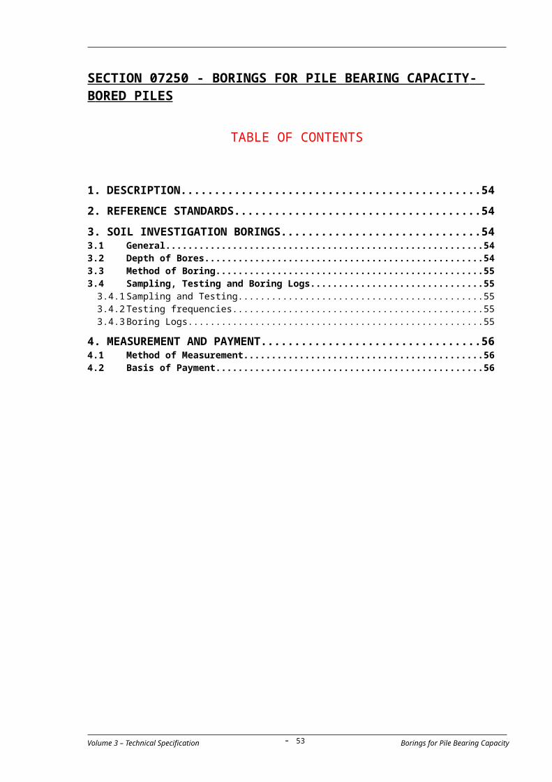
3.1.2 Stability of Pile Excavation using Drilling Fluid
(a) Where the use of drilling fluid is approved for maintaining the stability
of a bore, the level of the fluid in the excavation shall be maintained
so that the fluid pressure always exceeds the pressures exerted by
the soils and external groundwater or at not less than 1m above the
level of the external groundwater. An adequate temporary casing
may be required in conjunction with the method to ensure stability of
the strata near ground level until concrete has been placed.
(b) In the event of a rapid loss of bentonite suspension from the pile
excavation, the excavation shall be backfilled without delay and the
instructions of the Engineer shall be obtained before excavation at
that location is resumed.
3.1.3 Spillage and Disposal
All reasonable steps shall be taken to prevent spillage of bentonite
suspension at the site and in areas outside the immediate vicinity of bore.
Disposal of discarded bentonite shall be in accordance with the
Contractor’s approved environmental management plan. 3.1.4 Pumping from Bored Holes
Pumping from a bored hole will not be permitted unless a casing has been
placed into a stable stratum which prevents the flow of a significant
quantity of water from other strata into the bore, or unless it can be shown
that pumping will not have a detrimental effect on the surrounding soil or
adjacent property. 3.1.5 Cleanliness of Pile Bases
On completion of boring, loose, disturbed or remolded soil shall be
removed from the base of the pile, using appropriate and approved
methods, which may include airlifting, and which shall be designed to clean
while at the same time minimizing ground disturbance below the pile base. 3.1.6 Inspection
(a) For a boring without casing, the diameter of the boring hole for a
representative number of piles will be measured by calipers prior to
the placing of concrete into it. The Contractor’s Quality Control
personnel shall do the measurement using approved equipment.
(b) The Contractor shall provide an approved means by which inspection
of the verticality of bored piles and reinforcement cages can be
performed.
3.2 Final Pile Toe Level
(a) Where required as indicated on the drawings and prior to the
commencement of pile boring at each pile cap or structure, proposed
founding levels shall be established from site investigation boreholes
Volume 3 – Technical Specification Cast- in-situ pile- 53 -

(prebores) located at or near pile positions. Boreholes shall be in
accordance with requirements and procedures of Specification - Soil
Investigation Borings and/or as required by the Engineer. Where so
required, prebore results shall be submitted to the Engineer, at least
one month in advance of the piling work, to confirm the design of the
piles.
(b) During pile boring, the Contractor shall produce a boring log indicating
approximate depths and types of the various earth layers found in the
bore. Based on the existing conditions of boring, the Engineer might
require the Contractor to provide disturbed samples for visual
analysis.
(c) The Contractor shall immediately notify the Engineer if, during the
installation of piles, the ground conditions are different from those
indicated on the drawings or observed in the prebore.
(d) The Engineer will confirm the final pile toe level after his inspection of
the earth layers penetrated by the pile.
(e) The Contractor shall prepare for carrying out sampling and tests to
check bottom soils and excavation geometry.
3.3 Reinforcement
(a) Steel reinforcement shall be fabricated in accordance with the sizes
and dimensions shown on the drawings, and shall be placed, centered
and braced in the pile hole to the approval of the Engineer.
(b) Particular care shall be taken in locating projecting "column dowel
bars", with a tolerance not exceeding 10 mm in any direction, and
pouring will not be permitted until the Engineer is satisfied that
adequate provisions have been made.
(c) Adequate "shoes" or spacers shall be firmly anchored to the
reinforcement to ensure that the reinforcement is kept centered in the
concrete.
(d) The Contractor shall include in his construction method for pile
construction submitted to the Engineer for his approval, the working
drawings and details related to the placing of the reinforcement cage,
splicing procedures, measures and equipment to prevent damage to
the bored hole and maintain the stability of the bore while the cage is
being placed and procedures to control the verticality and consistency
of the cage during placing operations.
3.4 Concreting
(a) Immediately after the activities for boring excavation, placement of
reinforcement cage and cleaning of the borehole have been completed,
the Contractor shall request the Engineer’s approval for the
Volume 3 – Technical Specification Cast- in-situ pile- 54 -

commencement of concreting.
(b) Before placing concrete, measures shall be taken to ensure that there
is no accumulation of silt or other material at the base of the bore.
(c) Once the Engineer’s approval for the commencement of concreting has
been obtained, concreting shall start without delay and continue
without interruption. In a boring which contains water or drilling fluid
the concrete shall be placed by tremie.
(d) Concrete shall be a rich coherent mix of high workability having a
measured slump of 130 - 170 mm.
(e) Concrete shall be placed in such a manner that segregation does not
occur.
(f) During and after concreting care shall be taken to avoid damage to the
concrete due to pumping and dewatering operations.
(g) The hopper and pipe of the tremie shall be clean and watertight
throughout. The pipe shall extend to the base of the pile and a sliding
plug or barrier shall be placed in the pipe to prevent direct contact
between the first charge of concrete and the water. The pipe shall at
all times penetrate the concrete that has previously been placed and
shall not be withdrawn from the concrete until completion of
concreting. At all times a sufficient quantity of concrete shall be
maintained within the pipe to ensure that the concrete pressure
exceeds the water pressure. The tremie pipe shall be kept at least 2.0m
but never more than 5.0m. under the concrete level. The internal
diameter of the tremie pipe shall not be less than 150mm for concrete
made with 20mm aggregate and not less than 200 mm for concrete
made with 40mm aggregate. It shall be so designed that external
projections are minimized, allowing the tremie to pass through
reinforcing cages without causing damage. The internal face of the
pipe of the tremie shall be free from projections.
(h) Measurement of the level of concrete surface shall be taken
immediately before and after any vertical movement of the tremie
pipe.
(i) The Contractor shall ensure that heavily contaminated bentonite
suspension, which could impair the free flow of concrete from the pipe
of the tremie, has not accumulated in the bottom of the hole.
(j) A sample of the bentonite suspension shall be taken from the base of
the bore using an approved sampling device. If the specific gravity of
the suspension exceeds 1.25 the placing of concrete shall not proceed.
In this event, the Contractor shall modify or replace the bentonite as
approved to meet the specification.
Volume 3 – Technical Specification Cast- in-situ pile- 55 -

3.5 Extraction of Casing
3.5.1 Workability of Concrete
Temporary casings shall be extracted while the concrete within them
remains sufficiently workable to ensure that the concrete is not lifted.
Should a semi-dry mix be used the means of ensuring that the semi-dry
concrete does not lift during extraction of the casing shall be submitted to
the Engineer for his approval. 3.5.2 Concrete level
(a) When the casing is being extracted, a sufficient quantity of concrete
shall be maintained within it to ensure that pressure from external
water or soil is exceeded and that the pile is neither reduced in
section nor contaminated.
(b) Concrete shall be placed continuously as the casing is extracted until
the desired concrete level is obtained. The pile shall be cast to an
over-height approved by the Engineer to allow for cutting back to the
required level to ensure sound, uncontaminated concrete in the head
of the pile. No concrete shall be placed in the bore once the bottom of
the casing has been lifted above the top of the concrete.
(c) Adequate precautions shall be taken in all cases where excess
hydraulic heads could occur as the casing is withdrawn due to the
displacement of water by the concrete as it flows into its final position
against the walls of the shaft.
(d) The use of vibrating casing extractors shall be subject to the approval
of the Engineer.
3.5.3 Water Level
The Contractor shall submit to the Engineer for his approval suitable
proposals for dealing with groundwater levels higher than the required pile
head casting level shown on the drawings prior to placing concrete. The
pile head shall not be left below the groundwater level unless approved
precautions are taken.
3.6 Quality Control of Piling
3.6.1 General
The Contractor shall comply with his approved Quality Assurance Plan.3.6.2 Testing of Materials for Drilling Fluid
(a) Prior to the commencement of the work, the Contractor shall propose
the method and procedure of sampling and the frequency of testing
drilling fluid based on the referenced standards for drilling fluids. The
frequency may subsequently be varied depending on the consistency
of the results obtained.
(b) Control tests shall be carried out on the bentonite suspension using
Volume 3 – Technical Specification Cast- in-situ pile- 56 -

suitable apparatus. The density of freshly mixed bentonite suspension
shall be measured daily as a check on the quality of the suspension
being formed. The measuring device shall be calibrated to read to
within 0.01g/ml. Bentonite supplied to the pile bore shall be tested to
determine density, viscosity, shear strength and pH values. For
average boil conditions the results shall generally be within the ranges
stated in the table in this specification clause. The tests shall be
continued until a consistent working pattern has been established,
account being taken of the mixing process, any blending of freshly
mixed bentonite suspension and previously used bentonite suspension
and any process which may be used to remove impurities from
previously used bentonite suspension. When the results show
consistent behavior, the tests for shear strength and pH value may be
discontinued, and tests to determine density and viscosity shall be
carried out as approved by the Engineer.
(c) The Contractor shall submit to the Engineer for his approval the
method proposed for the sampling and checking of contaminated
bentonite and for the cleaning of the base of the bore. In the event of
a change in the established working pattern, tests for shear strength
and pH value shall be reintroduced for a period if required.
Property to be measured
Range of results at 20o C Test method
Density Less than 1.10g/ml Mud density balance
Viscosity 30-90s or Less than 20 cP
Marsh cone method Fann viscometer *
Shear strength(10 minute gel strength)
1.4-10 N/m2 or 4-40 N/m2
ShearometerFann viscometer
PH 9.5-12 pH indicator strips or electrical pH meter
* Where the Fann viscometer is specified, the fluid sample should be
screened by a # 52 sieve (300/um) prior to testing. 3.6.3 Piling
The Contractor shall designate a competent and experienced technician to
be in charge of the piling operations at the site and to be responsible for
the quality control of the work including, but not limited to, the following:
(a) Ensuring proper storage and handling of all the materials for pile
fabrication.
(b) Ensuring proper maintenance and cleanliness of plant (including that
for bentonite preparation), cranes, trucks, and other equipment.
(c) Work in close coordination with Contractor’s staff responsible for
quality control under other specification sections.
Volume 3 – Technical Specification Cast- in-situ pile- 57 -
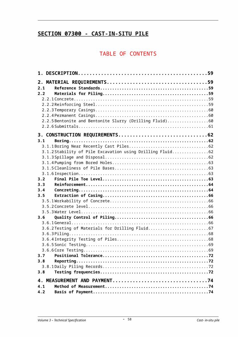
(d) Continuous monitoring of the quality of bentonite and other materials
used for piling.
(e) Proper preparation of the work before, during and after concrete
pouring.
(f) Proper preparation and performance for piles (including the Test Piles
if required according to the drawings or by the Engineer) as stated in
this specification.
(g) Proper preparation and timely submittal of the data and reports
specified in clause 3.8 of this specification.
(h) Preparation of working drawings, details, equipment related to the
measures to prevent, or to correct, defective piles or to be carried out
in the event that a borehole collapses during or before concreting
work.
3.6.4 Integrity Testing of Piles
The number of piles to be tested to determine their integrity shall be as
stated on the drawings. Testing shall be by Sonic Test and Core Test as
required by the Engineer.
For the purpose of testing the pile integrity by Sonic Test and core drilling,
all Cast-in-Situ piles shall be constructed with steel pipes cast in place as
detailed on the drawings.
All the following requirements shall be satisfied:
(a) The Contractor shall submit a complete plan of testing describing the
methodology and equipment to be used for testing.
(b) The length of steel tubing shall extend to the limits indicated on the
drawings.
(c) All tubing shall extend to at least 30 mm above the top of any
permanent or temporary pile casing.
(d) The bottom of the tube shall be permanently sealed
(e) The top of the tube shall be provided with a screw type plug, to
prevent the intrusion of foreign materials into the tube.
(f) Tubes shall be placed continuously straight from the bottom to the
top so as to allow later introduction of Sonic Coring and core drilling
apparatus.
(g) During placement, the tubes shall be kept free of all foreign
materials.
(h) The Contractor shall be responsible for any corrective work
necessary if testing and/or coring cannot be accomplished because
of improper placement and/or the presence of obstructions in the
tubing.
Volume 3 – Technical Specification Cast- in-situ pile- 58 -
(i) When required by the Engineer, the Contractor shall fill all tubes with
an expansive grout, acceptable to the Engineer, which is capable of
displacing any water in the tubes. The grout shall be continuously
injected into the tubes from the bottom of the tube to the top.
3.6.5 Sonic Testing
(a) Test shall not be carried out until the pile concrete has gained its 28
days characteristic strength.
(b) Sonic and Impulse Testing shall be carried out by approved specialist
firms, from whom a full method statement shall be obtained and
approved by the Engineer prior to commencement of testing. One
hundred percent (100%) of piles shall be tested .
(c) The interpretation of the results shall be carried out by competent
persons and an indication of the result of all testing shall be passed to
the Engineer immediately on completion of all tests. A full written
report shall be provided directly to the Engineer within 10 days after
the completion of the test.
3.6.6 Static load test on ‘’ working piles’’
The contractor shall submit his proposal for conducting static load tests to
the Engineer for this approval.
Unless otherwise directed by the Engineer the test load shall be applied in
the following sequence:
(a) Apply an initial load of 5% required pile – working load.
(b) Remove the initial load and set recording instruments to zero.
(c) Increase load to the required pile-working load, as shown on the
Drawings, by four equal increments.
(d) Deflection shall be read just after each load increment or
decrement is applied and at 15 minutes intervals thereafter. The
next increment or decrement shall not be applied until the rate of
settlement has decreased to 0.05 cm/hour and the load has been
sustained for at least one hour.
(e) The pile-working load shall be maintained for at least 12 hours.
(f) Reduce load to zero by similar equal decrements.
(g) Increase load to 1.5 times the required pile-working load by six
equal increments and maintain at this load for at least 24 hours.
(h) Reduce load to zero by similar equal decrements.
Volume 3 – Technical Specification Cast- in-situ pile- 59 -

(i) When directed by the Engineer, a third test cycle shall be carried
out as follows:
Increase load to 2.0 times the required pile working loads by eight equal increments and maintain at this load for 12 hours or as directed by the Engineer.
(j) For acceptance, the total pile top displacement under 1.5 times pile
working load and after its subsequent removal shall not exceed the
following values:
Loaded Unloaded
For bored cast-in-place piles1.5%
0.75%
of the pile diameter
(k) Instrumentation shall be installed as directed by the Engineer and
readings taken at each increment, all in accordance with the
manufacturer’s recommended procedures.
Test Results on Pilot and Working Piles
(a) The Contractors shall submit within 48 hours of the completion of
the pile test to the Engineer for each pile tested a detailed record
of testing and, in addition, graphs showing:
Load and pile top displacement plotted above and below a
common base line of time for static load tests.
Pile top displacement plotted vertically against a base line of
load for static load tests.
Top pile displacement Vs mobilized static resistance plot as
assessed from dynamic load test using CAPWAP – Method.
(b) A full comprehensive written report shall be submitted to the
Engineer within 10 working days for approval.
(c) After the completion of loading tests, all equipment and load used
shall be removed from the site.
(d) If the results of the load tests on “Working piles” shall be
considered as not having complied with the criteria specified or
required a further pile shall be tested. If this second pile test also
does not comply with specifications or requirements, the Engineer
shall order changes to the pile group as he considers necessary.
Volume 3 – Technical Specification Cast- in-situ pile- 60 -

New pile or piles shall be installed to replace the defective pile in a
position or positions as instructed by the Engineer.
3.6.7 Core Testing
(a) As required by the Engineer, core drilling shall be provided for
completed piles to at least 600 mm below the bottom of the pile. The
cores obtained shall be placed in core boxes and the drill-hole
identification shall be clearly marked on each respective core and
box. Three (03) samples shall be taken from 2% of piles.
(b) Upon satisfactory completion of tests, all voids formed by core drills
shall be pressure grouted with non-shrink grout in accordance with
this specification.
3.7 Positional Tolerance
The positional tolerances for cast in-situ piles shall be as follows:-
a) The centre of the completed pile at the cut off level shall not deviate more than 80mm from the theoretically correct position shown on the Drawings.
b) The inclination of the pile shall not deviate more than 1:100 from the required vertical alignment.
c) After completion of all piling work and prior to casting the pile top into the pile cap or foundation, the top of the reinforcement cage shall be no more than 150 mm above and no more than 75 mm below the correct position and the top of the concrete shall be within 25 mm of the correct elevation.
d) The bottom of the shaft excavation shall be normal to the axis of the pile within 60 mm per meter of pile diameter
e) Where a casing is used, its outside diameter shall not be less than the shaft diameter shown on the Drawings. The diameter of cast in-situ piles shall be at least 97% of the specified diameter
3.8 Reporting
3.8.1 Daily Piling Records
The Contractor shall furnish the Engineer with a detailed daily record of
soils encountered during excavation and construction of the piles.
The Contractor shall keep records of the installation of each pile and shall
submit two signed copies of these records to the Engineer not later than
24 hours after the pile was installed. The signed records shall be as
indicated in the following table.
Table 1 Records of pile borings:
(a) Contract Name and Date
(b) Pile reference number (location)
Volume 3 – Technical Specification Cast- in-situ pile- 61 -
(c) Pile type
(d) Nominal cross-sectional dimensions or diameter
(e) Nominal diameter of under-ream
(f) Length of performed pile
(g) Standing groundwater level
(h) Date and time of boring
(i) Date of concreting
(j) Ground level at commencement
(k) Working level
(l) Depth from working level to pile toe
(m) Toe level
(n) Depth from working level to pile head level
(o) Length of temporary casing
(p) Length of permanent casing
(q) Vertical of borehole
(r) Set of pile or pile tube in mm per 10 blows or number of blows per 25 mm of penetration
(s) Soil samples taken and in-place tests carried out
(t) Length and details of reinforcement
(u) Concrete mix
(v) Volume of concrete supplied to pile where this can be measured in practice and corresponding levels of concrete and casing
(w) All information regarding obstructions, delays and other interruptions in the sequence of work
(x) Strength of corresponding concrete cylinders
(y) If grouting done, mix and quantity of grout used.
3.9 Testing frequencies
Testing frequencies shall be accordance with Vietnamese Standard: TCVN 326-04 or 22TCN 257-2000 or other international standard subject equivalence being demonstrated by the Contractor and the satisfaction of the Engineer of the Vietnamese standard shall apply:
Item Test Description
Test Frequency Remark
1 TCXDVN 326-04 or 22TCN 257-2000 : Bored pile - Code of Construction and acceptance standard
a
Material testing & preparation work before construction: (for material & quarries approval)
Bentonite liquid : Article 11.2 Table 1 Cement concrete for bore piles : Article 11.5
Volume 3 – Technical Specification Cast- in-situ pile- 62 -
b During construction period:
Boreholes checking : Article 11.3Table 2; Table 3
Reinforcemnet grid tolerance : Article 11.4 Table 4 Cement concrete for bore piles : Article 11.5 Table 5
cAfter construction period: (For acceptance of construction works)
Loading testing for bore plies : Article 11.6 (static load, & PDA)
4. MEASUREMENT AND PAYMENT
4.1 Method of Measurement
The Cast-in-Situ piles shall be measured for payment by linear meters of
piles cast and left in place in the completed and accepted work.
Measurement shall be made from the bottom of the pile to the bottom of
the foundation (the lower plane as defined for structural excavation)
indicated on the Drawings. Portions of piles cast deeper than required
through over-excavation procedures shall not be measured for payment.
In case that the presence of an obstruction affects the construction works,
the Contractor shall immediately submit to the Engineer, for approval, his
proposed countermeasures and detailed schedule to avoid delays in the
Project. In the event that the requirements for the before mentioned
investigation on the existing site conditions are not duly complied by the
Contractor, no time extension and neither additional payment shall be
allowed for the countermeasures, and the materials and incomplete works
performed by the Contractor before encountering the obstruction shall not
be subject to any payment.
4.2 Basis of Payment
The accepted quantities, measured as provided above, shall be paid at the
contract price per unit of measurement for the pay items of the Bill of
Quantities listed below.
Payment shall be full compensation for the work prescribed in this Section
including, but not necessarily limited to, the following:
(1) Cast-in-Situ Piles
All of the cost mentioned bellow is included.
① Placement of cage for reinforcement, integrity testing tubing, protection of existing piles and structures, hauling, handling, jetting, jointing, cutting and all other incidental works related thereto
② all expenses involved in providing pumps, cofferdams, braced sheet piling or any other methods approved by the Engineer;
③ all expenses resulting from the Contractor's
Volume 3 – Technical Specification Cast- in-situ pile- 63 -

observance of all rules and regulations of relevant competent authorities regarding the interference or maintenance of flow in the canals, water courses, channels or pipes related to the Project
④ provisions for and driving and removal of sheet piles including providing certification by an Independent Engineer;
⑤ provisions for placement and removal of temporary Jetty/Guide frames;
⑥ provisions for underwater works;
⑦ provisions for underwater concrete;
⑧ previsions for pumps and dewatering by submersible pumps;
⑨ provisions for all necessary barges; and
⑩ provisions for all necessary tugboats and auxiliary river craft.
⑪ And for furnishing all labor, materials, tests, tools, equipment and any incidentals to complete the work as shown on the Drawings and as required by these Specifications, and/or as directed by the Engineer.
(2) Permanent Casing
Payment shall include all expenses for furnishing materials, equipment
and instruments, technicians and experts for completion of the
installation of permanent casing as described in clause 2.2.4.
Temporary casing shall be considered incidental to the prices in the Bill
of Quantities and shall not be paid for separately.
(3) Pile Core Tests
Payment shall include all expenses for furnishing all materials,
equipment and instruments, technicians and experts for completion of
the pile core tests.
Pay Item Description Unit
07300 – 01
07300 - 02
Cast-in-Situ Pile 1,200 mm diameter (in land)Cast-in-Situ Pile 1,200 mm diameter (on water)
lmlm
07300 – 03
Permanent Casing (1,200 mm) lm
07300 – 04
Pile Core Test each
07300 – 05
Static pile Test Nos
07300 – 06
Humus testing at top pile Nos
07300 – 07
Ultrasonic Test section
Volume 3 – Technical Specification Cast- in-situ pile- 64 -

North – South Expressway Construction Project Tender documents(Ho Chi Minh – Dau Giay Section) Contract Package 1A
Volume 3 – Technical Specification Pile DynamicTesting- 65 -

North – South Expressway Construction Project Tender documents(Ho Chi Minh – Dau Giay Section) Contract Package 1A
SECTION 07350 – PILE DYNAMIC TESTING
1. DESCRIPTION....................................................................67
2. EQUIPMENT AND MATERIAL REQUIREMENTS.......................67
3. SPECIALIST.......................................................................68
4. REPORTING RESULTS.........................................................68
5. METHOD OF PAYMENT.......................................................68
6. BASIS OF PAYMENT...........................................................69
Volume 3 – Technical Specification Pile DynamicTesting- 66 -
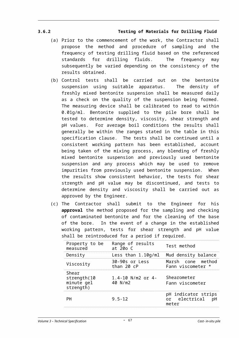
North – South Expressway Construction Project Tender documents(Ho Chi Minh – Dau Giay Section) Contract Package 1A
1. DESCRIPTION
The work shall consist of furnishing all materials, equipment, and labour necessary for conducting high-strain dynamic tests on drilled and cast-in-place piles. 2% of all completed piles shall be selected for testing as approved by the Engineer. The Contractor shall appoint an Independent Specialist to conduct all testing and shall supply materials, equipment and labour as specified, for work prior to, during, and after the tests all to the approval of the Engineer. Testing procedures shall conform to ASTM D4945-89 unless noted otherwise. The shaft used for the test will be instrumented and tested by the Independent Specialist, as approved by the Engineer, meeting requirements outlined in the ASTM D4945-89 specification as well as those outlined below.
2. EQUIPMENT AND MATERIAL REQUIREMENTS
The Contractor shall supply all labour, materials and equipment required to prepare and dynamically load the test pile, and return the pile to a condition suitable for use in the finished structure. The Contractor’s equipment and methods shall include but not be limited to:
The extension of the pile top if a permanent casing has not been used to construct the pile. The extension shall be formed of a thin walled casing or equivalent and shall be at least equal to two and a half (2 ½) pile diameters such that the extended pile head can be readily accessed by the testing engineer at the time of the test. If the pile top is below grade, the Contractor shall remove the surrounding soil to expose the pile top in a safe working environment.
A flat, level, and sound concrete top to the pile perpendicular to the vertical axis of the pile. The top of the concrete should be level with or above the casing. Prior to the test, four “windows” approximately 150mm. by 150mm. shall be provided in each quadrant of the casing.
A drop weight in the range of one and half to two percent (1.5% to 2%) of the anticipated pile capacity to be approved by the Engineer.
A guide allowing variable drop heights typically between 2 to 3m to be approved by the Engineer.
A shaft top cushion consisting of new sheets of plywood with total thickness between 50mm. and 150mm. to be approved by the Engineer.
A steel striker plate at least 50mm. thick and an area between 70% and 90% of the area of the pile top, but not less than the area of the impacting surface of the drop weight, shall be placed on top of the plywood cushion.
Where reinforcement protrudes above the top of the pile the Contractor may:
Incorporate the reinforcement into the test area in the manner of a pile extension. Upon successful completion of the
Volume 3 – Technical Specification Pile DynamicTesting- 67 -
North – South Expressway Construction Project Tender documents(Ho Chi Minh – Dau Giay Section) Contract Package 1A
dynamic test the extension can be removed to make the pile suitable for use in the structure.
Ensure at least 20% of the pile cross sectional area is available for sufficient length such that the ram impact will not interfere with the reinforcing bars. In such case steel striker plates and plywood cushions must be sized so that they cover as much as the impact area as possible.
One (1) k of 200 Volt AC Power.
Surveyor’s level, laser light or equivalent for measurement of pile set under each impact.
3. SPECIALIST
Testing is to be performed by an accredited Specialist from a firm with a minimum of four (4) year experience in dynamic load testing. The actual test shall be conducted and/or supervised by a practicing Geotechnical Engineer with at least five (5) years of dynamic testing experience. The firm selected by the Contractor must be approved by the Engineer.
The Specialist must supply the following testing instrumentation in addition to instrumentation outlined in ASTM specification D4945-89 Section 5:
a) Pile Driving Analyzer (PDA)
b) Calibrated Strain Transducers
c) Calibrated Accelerometer
4. REPORTING RESULTS
The Specialist shall promptly submit a report of the testing results to the Engineer for approval. The field results from at least one (CAPWAP) analysis (case Pile Wave Analysis Program) shall be submitted. The CAPWAP analysis shall be performed by an experienced and qualified Engineer. The report shall also provide the following:
a) Wave Equation analysis results obtained prior to testing
b) CAPWAP analysis result.
c) For each impact the maximum measured force, maximum calculated tension force, transferred energy to the gage location, corresponding stresses, and the Case Method bearing capacity.
d) Assessment of the test result with respect to both pile capacity and integrity.
5. METHOD OF PAYMENT
Volume 3 – Technical Specification Pile DynamicTesting- 68 -

North – South Expressway Construction Project Tender documents(Ho Chi Minh – Dau Giay Section) Contract Package 1A
The quantity to be paid for shall be the number of bored piles tested and accepted. Any item indicated and not otherwise described hereto shall be considered subsidiary to the work item and shall not be paid for separately.
6. BASIS OF PAYMENT
Payment shall be made for each test together with the relevant report accepted by the Engineer at the contract price shown below. The payment shall constitute full compensation for the cost of Pile Dynamic Testing, the cost of appointing an Independent Specialist, all instrumentation, testing and testing equipment, analysis and reporting, tools, labour and all other incidentals necessary to complete the work prescribed in this Item.
Payment will be made under:
Pay Item Number
Description Unit
07350 – 01 PDA tests Nos
Volume 3 – Technical Specification Pile DynamicTesting- 69 -
North – South Expressway Construction Project Tender documents(Ho Chi Minh – Dau Giay Section) Contract Package 1A
SECTION 07400 - PRESTRESSED CONCRETE
TABLE OF CONTENTS
1. DESCRIPTION....................................................................71
2. MATERIAL REQUIREMENTS.................................................712.1 Reference Standards.....................................................................712.2 Material for Prestressed Concrete..................................................71
2.2.1 General Requirement......................................................................................712.2.2 Prestressing Steel............................................................................................712.2.3 Anchorages for post tensioning.......................................................................722.2.4 Ducts (Sheath)................................................................................................732.2.5 Grout for Ducts................................................................................................732.2.6 Concrete.........................................................................................................742.2.7 Submittals.......................................................................................................74
3. CONSTRUCTION REQUIREMENTS........................................753.1 General.........................................................................................753.2 Sampling and Testing....................................................................76
3.2.1 Grouting Trials.................................................................................................763.2.2 Site Flow Tests.................................................................................................773.2.3 Testing of Pre-cast Pre-stressed Members.......................................................77
3.3 Placing Steel.................................................................................773.4 Pretensioning Method...................................................................773.5 Post-tensioning Method.................................................................783.6 Grouting.......................................................................................79
3.6.1 Plant for Grouting............................................................................................793.6.2 Grouting of Ducts and Sheathing....................................................................79
3.7 Protection of Prestressing Anchorages...........................................803.8 Superstructure Construction..........................................................813.9 Curing...........................................................................................82
3.9.1 General...........................................................................................................823.9.2 Steam Curing..................................................................................................82
3.10 Handling, Transport and Storage....................................................833.11 Marking of Precast Prestressed Members.......................................833.12 Erection of Pre-cast Beams............................................................833.13 Tolerances for Pre-stressed Concrete Structures.............................843.14 Testing frequencies.......................................................................84
4. MEASUREMENT AND PAYMENT...........................................854.1 Method of Measurement................................................................864.2 Basis of Payment...........................................................................86
Volume 3 – Technical Specification Prestressed Concrete- 70 -

North – South Expressway Construction Project Tender documents(Ho Chi Minh – Dau Giay Section) Contract Package 1A
1. DESCRIPTION
(a) This work consists of the construction of pre-stressed concrete
structures and pre-stressed concrete portions of composite structures in
conformity with the design, lines, grades, and dimensions shown on the
drawings or as may be established by the Engineer in accordance with
this and other relevant specifications.
(b) The work shall include the supply and installation of any items
necessary for the particular pre-stressing system to be used, including
but not limited to ducts, anchorage assemblies and grout used for
pressure grouting ducts.
(c) It shall include the manufacture, transportation, and storage of beams,
slabs, and other structural members of pre-cast concrete pre-stressed
by either pre tensioning or post-tensioning methods. It shall also
include the installation of all pre-cast pre-stressed members.
2. MATERIAL REQUIREMENTS
2.1 Reference Standards
The following Standards in their latest edition shall be particularly applied to
the works covered by this Specification.
AASHTO M235 Epoxy Resin Adhesives
22TCN 272-05 Specification standard for Bridge design
AASHTO LRFD Bridge Design Specifications, Deflection Criteria for Girders, Section 2.5.2.6.2.
ASTM A421-91 Un-coated Stress Relieved Steel Wire for Prestressed Concrete;
ASTM A416-99 Steel Strand, Un-coated Seven Wire Stress Relieved Strand for Prestressed Concrete.
2.2 Material for Prestressed Concrete
2.2.1 General Requirement
All materials to be furnished and used, but not covered in this specification,
shall conform to the requirements stipulated in other applicable
specifications. 2.2.2 Prestressing Steel
(a) High tensile strength steel wire shall be stress relieved and shall
conform to the requirements of ASTM A421-91 or equivalent for Un-
coated Stress Relieved Steel Wire for Pre-stressed Concrete
(b) High tensile steel strand with low-relaxation shall be weld free and
stress relieved after stranding and shall conform to the requirements
of ASTM A416-99 or equivalent Steel Strand, Un-coated Seven Wire
Stress Relieved Strand for Prestressed Concrete
(c) Testing of pre-stressing reinforcement shall be in accordance with the
Volume 3 – Technical Specification Prestressed Concrete- 71 -

North – South Expressway Construction Project Tender documents(Ho Chi Minh – Dau Giay Section) Contract Package 1A
requirements of the ASTM Specifications for the type of system
intended to be used or subject to approval by the Engineer.
Fpu – Specsified tensile strength of pretressing steel (Mpa)
Fpy – Yield strength of pretessing steel (Mpa)
2.2.3 Anchorages for post tensioning
(a) All anchorage assemblies shall be subject to the approval of the
Engineer.
(b) All post-tensioned pre-stressing steel shall be secured at the ends by
means of approved permanent type anchoring devices. The
Contractor shall submit information and details, including test
certifications for by the Engineer.
(c) End anchorage devices (stress and dead anchors) shall be designed
Volume 3 – Technical Specification Prestressed Concrete- 72 -

North – South Expressway Construction Project Tender documents(Ho Chi Minh – Dau Giay Section) Contract Package 1A
and manufactured for the types of tendons to be used. They shall
have a previous service record of performance and durability when
used on similar type work.
(d) All anchorage devices for post-tensioning shall be capable of holding
the pre-stressing steel at a load producing a stress of not less than 95
percent of the guaranteed minimum tensile strength of the pre-
stressing steel.
(e) Fixed anchorages for tendons in pre-cast beams shall be of steel
bearing plate type while all remaining anchorages shall be those
capable of adjustment by means of a threaded anchor head and ring
nut.
(f) It shall be the responsibility of the Contractor to confirm the required
bursting reinforcements in the local zone for the particular shape and
design of the anchorage devices proposed.
(g) All externally exposed steel parts shall be protected from corrosion.
All threaded parts and fittings shall be protected by greased
wrappings or plugs until used. Anchorages shall be kept free from
dirt, mortar, loose rust or other deleterious materials. Damaged
anchorage parts shall not be used.
2.2.4 Ducts (Sheath)
(a) Ducting for internal tendons shall be fully compatible with the
proposed pre-stressing system. The ducts shall be fabricated from
corrugated galvanized sheet steel or semi-rigid conduit.
(b) Minimum duct thickness shall be as follows:
* 26 gauge for duct diameter less than or equal to 67 mm
* 24 gauge for duct diameter greater than 67 mm
* 31 gauge for bar tendons
(c) Ducts shall have grouting connections at each end and shall have
vent/drains at all intermediate high and low points, subject to the
approval of the Engineer.
2.2.5 Grout for Ducts
Unless otherwise specified in other prevailing sections, or subject to
approval by the Engineer as a result of grouting trials, the grout shall:
(a) consist only of ordinary Portland cement, water and expansive
admixtures approved by the Engineer and used in accordance with
the manufacturer’s instructions;
(b) have a water to cement ratio as low as possible consistent with the
necessary workability, and under no circumstances shall the
water/cement ratio exceed 0.40;
Volume 3 – Technical Specification Prestressed Concrete- 73 -
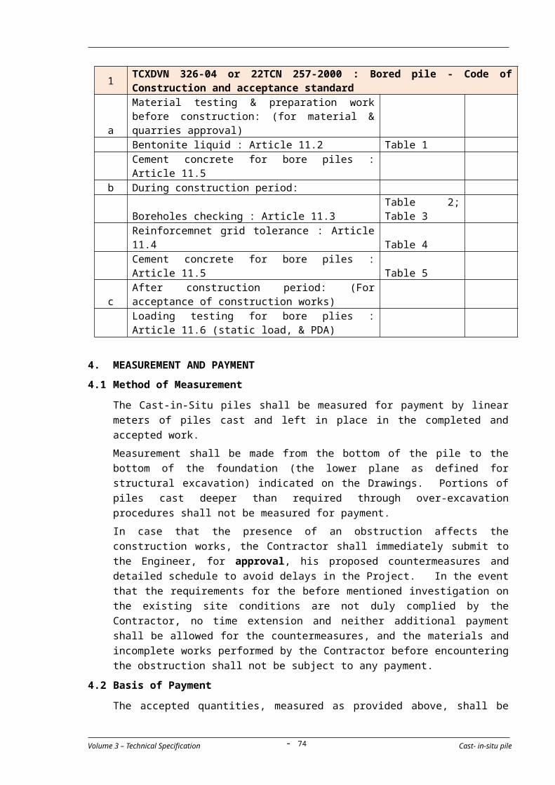
North – South Expressway Construction Project Tender documents(Ho Chi Minh – Dau Giay Section) Contract Package 1A
(c) not contain admixtures containing chlorides, nitrates or similar
electrolytic conducting materials.
2.2.6 Concrete
(a) Concrete shall be of the class indicated on the drawings and shall
conform to the requirements of Specification - Concrete and Concrete
Structures and the requirements specified below unless otherwise
stated on the drawings or as may be required by the Engineer.
(b) The maximum size of aggregate for use in the manufacture of pre-
stressed concrete shall be 25 millimeters.
(c) The main properties of concrete such as compressive strength after
28 days, Modulus of Elasticity (Young Modulus), and other properties
that were used for the detailed design shall be confirmed by testing
of samples of the approved mix design. The Contractor shall perform
the tests in accordance with the appropriate standards, or as may be
required by the Engineer.
2.2.7 Submittals
The Contractor shall prepare, check and submit detailed Contractor’s
Drawings and Schedules together with calculations to the Engineer for his
review and approval well before superstructure construction is
programmed to start. Details and design shall be checked by a properly
qualified engineer who shall confirm the adequacy and safety of the
proposed details by certifying and stamping the designs and drawings.
Expenses incurred in connection with this certification shall be borne by
the Contractor. Concrete shall not be cast prior to the Engineer’s approval
of these requirements.
The Contractor’s submittals shall include where required, but not limited
to, the following:
Geometry Control PlanDetailed procedures and methods for controlling the geometry at every stage of construction.
Temporary worksTemporary fixing/stabilizing method of the supports and closures during erection operationsTravelling forms, suspended false-work or scaffolding, girder erection gantriesForm-work and false-workDimensions and complete descriptions of all devices, joints, bearings, and anchorages not specified or detailed in the Specifications
Pre-stressingMethod and timing of the insertion of pre-stressing cables.Post-tensioning or Pre-tensioning hardware, jointing, jacking, grouting equipment, and men and materials of any kindVertical alignment and deflection control measures with calculations
Volume 3 – Technical Specification Prestressed Concrete- 74 -
North – South Expressway Construction Project Tender documents(Ho Chi Minh – Dau Giay Section) Contract Package 1A
of pre-camber by pre-stressing forces, loads, temperature range and effects of creep and shrinkage of concrete
GroutingStatement for grouting of ducts
Casting and curing Detailed Casting Manual describing all the activities in a step-by-step procedure Methods of controlling of deflection to ensure the accuracy of alignment of the completed superstructure
Erection of members Equipment for all machinery, devices, labor and material which are to be used for erectionMethods of tie-down and closure of superstructures during erection
Cross Beam Installation and pre-stressing methods of cross beam
Deck Slab Fabrication and Installation methods of Concrete Form Works
Installation methods of Cast in Situ Slab on the Concrete Form Works
3. CONSTRUCTION REQUIREMENTS
3.1 General
(a) The Contractor shall assign an experienced technician, skilled in the
use of pre-stressing system, who shall supervise the work being
performed in compliance with these specifications and to the
satisfaction of the Engineer.
(b) The Contractor shall provide all equipment necessary for construction
and pre-stressing. The equipment shall be of a currently manufactured
model, and shall be in good working condition. A pre-stressing system
approved by the Engineer shall be used. If hydraulic jacks are used
they shall be equipped with accurate pressure gauges. The
combination of jack and gauge shall be calibrated and a graph or table
showing the calibration shall be provided to the Engineer. Should other
types of jacks be used, calibrated proving rings or other devices shall
be furnished so that the jacking forces may be accurately known.
(c) The requirements for concrete construction in Specification - Concrete
and Concrete Structures shall be complied with, except as may be
modified in this specification. Pre-stressed concrete shall be formed,
stressed, placed, cured, and protected at shops, manufacturing plants,
and locations where the fabrication of such members may be properly
inspected and controlled and approved by the Engineer.
(d) Vertical alignment and girder lengths shown on the drawings represent
dimensions at the time of final creep. Deflection criteria for girders
shall be in accordance with 22 TCN 272-05, longitudinal deflections
may be rectified by an appropriate approved method.
Volume 3 – Technical Specification Prestressed Concrete- 75 -

North – South Expressway Construction Project Tender documents(Ho Chi Minh – Dau Giay Section) Contract Package 1A
3.2 Sampling and Testing
3.2.1 Grouting Trials
(a) Where full scale trials are required they shall begin at least 21 days
before the planned commencement of the fixing of ducts for pre-
stressing in the permanent works unless otherwise specified in the
Contract.
(b) The trials shall incorporate all relevant details of ducts, vents, duct
supports, pre-stressing anchorages and couplers, pre-stressing
strands and grout inlets and outlets. Tendons shall be sufficiently
tensioned such that the strands within the duct take up a
representative alignment. All systems, methods and materials shall
be those proposed for the permanent works and shall have been
submitted to the Engineer as part of the Contractor’s detailed method
statement.
(c) Grouting shall be carried out in accordance with the requirements of
Sub-section 3.6.2 of this specification, and the following information
shall be recorded:
* fluidity of the grouting using a flow cone;* results of bleeding tests;* compressive strength of the grout;* temperature of the grout at the point of injection;* shade temperature;* grouting pressure close to the point of injection;* type of any admixture and results of control tests carried out by
the manufacturer to demonstrate its properties including those at appropriate hydration temperatures; and
* results of a visual inspection for detection of leakage.
(d) The arrangement of ducting, end plates injection and outlet
connections shown on the drawings shall be rigidly supported and an
actual or simulated bar tendon inserted but not stressed.
(e) After the grout strength has reached 17 Mpa, at least three samples,
each one of 1 meter long, shall be cut from the grouted duct at the
locations chosen by the Engineer. Each of the samples shall be
sectioned longitudinally by cutting with a high speed abrasive cutting
wheel, friction saw or similar. The sectioned samples shall be
delivered to the Engineer, who will assess the acceptability of the
grouting trials particularly in respect of the presence and location of
any voids in the samples.
(f) If the presence and location of voids are deemed to be unacceptable,
the Contractor shall amend the properties of the grout and/or
grouting procedures and carry out further trials, until an acceptable
result is obtained.
(g) Before commencing grouting trials the Contractor shall submit to the
Volume 3 – Technical Specification Prestressed Concrete- 76 -
North – South Expressway Construction Project Tender documents(Ho Chi Minh – Dau Giay Section) Contract Package 1A
Engineer details of the proposed ducting, method of support and
calculations substantiating that the ducting and any surrounding
supporting material will withstand the grouting pressure used during
the trials.
3.2.2 Site Flow Tests
Fluidity of the grout shall be tested on site at the time of mixing using the
Marsh Cone Test to ensure practicality of pumping and minimize the risk of
blockage during grouting operation. A target flow time of 10-15 seconds
shall be achieved. 3.2.3 Testing of Pre-cast Pre-stressed Members
Where required by the Engineer, one or more beams may be subjected to a
loading test. The Contractor shall obtain the prior approval of the Engineer
for the detailed arrangements for testing. The cost of tests and records
shall be included in the unit prices.
3.3 Placing Steel
All steel reinforcement shall be accurately placed in the position shown on
the drawings and rigidly held in place during placing and setting of the
concrete. Distance from the forms shall be maintained by stays, formwork
spacers, ties, hangers, or other approved support. Formwork spacers for
holding units from contact with the forms shall be of approved material,
shape and dimensions. Layers of reinforcement shall be separated by
suitable wire spacers. Wooden blocks shall not be used.
3.4 Pretensioning Method
(a) The pre-stressing elements shall be accurately held in position and
stressed by jacks. Stressing shall be applied to produce the stresses
required in the wires, strands or bars immediately after the anchorage
as shown on the drawings or as directed by the Engineer. Suitable
allowances shall be made for friction in the jacks and for slip and yield
in the grips or anchorages.
(b) Curing shall be by steam methods as described in clause 3.9.2, or
other methods subject to the approval of the Engineer.
(c) A record shall be kept of the jacking forces and the elongations
produced and the minimum age in hours of the concrete for each unit
until the time the tendons were released.
(d) No bond stress shall be transferred to the concrete, nor shall end
anchors be released, until the concrete has attainted a compressive
strength of not less than 85% of the specified 28-day strength as
shown by standard specimens cured in a similar fashion to the
element. The elements shall be cut or released in such an order that
eccentricity of pre-stress is minimized subject to the approval of the
Engineer.
Volume 3 – Technical Specification Prestressed Concrete- 77 -

North – South Expressway Construction Project Tender documents(Ho Chi Minh – Dau Giay Section) Contract Package 1A
3.5 Post-tensioning Method
(a) Post-tensioning shall be carried out in accordance with an approved
method and in the presence of the Engineer unless permission has
been obtained to the contrary.
(b) Immediately before tensioning, the Contractor shall prove that all
tendons are free to move in the ducts.
(c) Each anchorage device shall be set square to the line of action of the
corresponding post-tensioning tendon and shall be securely fixed in
position and gradient to prevent movement during the placing and
compaction of concrete.
(d) Except where dead-end anchorages are cast in the concrete, tendons
shall not be installed until just prior to stressing. Tendons shall be
pulled or pushed through the duct in such a manner as to avoid
damage to either the tendon or the duct.
(e) Unless approved otherwise, concrete shall not be stressed until 2 test
cylinders taken from it have attained the specified transfer strength.
The test cylinders shall be cured in conditions similar to the concrete to
which they relate in a manner approved by the Engineer.
(f) Where members consist of jointed elements, the strength of transfer of
the jointing material shall be at least equivalent to the specified
transfer strength of the members.
(g) The Contractor shall establish the datum point for measuring extension
and jack pressure to the satisfaction of the Engineer. Allowance shall
be made for the friction in the jack and anchorage for pull-in of the
tendon during anchorage.
(h) The tendons shall be stressed at a gradual and steady rate until the
required extension and tendon load are reached or are approved by the
Engineer. The sequence of stressing shall be as shown on the drawings
or directed by the Engineer.
(i) The force in the tendons shall be obtained from readings on a load cell
or pressure gauge incorporated in the equipment and the extension of
the tendons measured. The extension of the tendons under the
approved total forces shall be within the limits given below of the
agreed calculated extension.
Transverse Tendons for Segments:
±10% average for one tendon
± 7% for average of one segment
Longitudinal Tendons for Segments
± 5%
All other Tendons ± 5%
Volume 3 – Technical Specification Prestressed Concrete- 78 -
North – South Expressway Construction Project Tender documents(Ho Chi Minh – Dau Giay Section) Contract Package 1A
(j) If the measured extensions are not within the specified tolerance then
the Contractor shall submit to the Engineer his method of rectifying the
discrepancy.
(k) When the pre-stressing force has been applied to the satisfaction of the
Engineer, the tendons shall be anchored. The force exerted by the
tensioning apparatus shall then be decreased gradually and steadily so
as to avoid shock to the tendon or anchorage.
(l) Full records shall be kept of all tensioning operations including
measured extensions, pressure gauge or load cell readings and draw-in
at anchorage. Copies of records shall be supplied to the Engineer
within 24 hours of each tensioning operation.
(m) Unless otherwise agreed by the Engineer, tendons shall not be cut less
than 2 days after stressing.
3.6 Grouting
3.6.1 Plant for Grouting
(a) The grout mixer shall produce a grout of colloidal consistency. The
grout injector shall be capable of continuous operation with a sensibly
constant pressure up to 0.70-N/mm2 and shall include a system of
circulating or agitating the grout whilst actual grouting is not in
progress. All baffles to the pump shall be fitted with 1.18 mm sieve
strainers.
(b) The equipment shall be capable of maintaining pressure on
completely grouted ducts and shall be fitted with a nozzle that can be
locked off without loss of pressure in the duct.
(c) The pressure gauges shall be calibrated before they are first used in
the Works, and thereafter as required by the Engineer. All equipment
shall be thoroughly cleaned and washed with clean water at least
once every 3 hours during the grouting operations and at the end of
use for each day.
(d) During the grouting operation, the Contractor shall provide adequate
flushing-out plant to facilitate complete removal of the grout in the
event of a breakdown of the grouting equipment or other disruption
before the grouting operation has been completed.
3.6.2 Grouting of Ducts and Sheathing
(a) Grouting trials shall be undertaken when directed by the Engineer.
Prior to using the grout in any trial or in the works the Contractor shall
submit a detailed method statement for grouting procedures covering
proposed materials, sheathing, anchorage and vent alignment
equipment, and quality control to the Engineer for his approval.
(b) All ducts shall be thoroughly cleaned out by means of flushing with
Volume 3 – Technical Specification Prestressed Concrete- 79 -

North – South Expressway Construction Project Tender documents(Ho Chi Minh – Dau Giay Section) Contract Package 1A
water and/or water/compressed air.
(c) Grouting of ducts shall be carried out as soon as it is technically
practicable, but not more than 4 weeks after the tendons inside the
ducts have been stressed, and the Engineer’s permission to
commence grouting has been obtained. If due to the requirements of
the stressing procedure, tendons cannot be grouted within 4 weeks
the sheathing shall be sealed to protect the tendons from corrosion.
(d) Injection shall be continuous and slow enough to avoid producing
segregation of the grout. The method of injecting grout shall ensure
complete filling of the ducts and complete surrounding of the steel.
Grout shall be allowed to flow from the free end of the duct until its
consistency is equivalent to that of the grout injected. The opening
shall then be firmly closed. Any air vents shall be closed in a similar
manner one after the other in the direction of flow. The injection
tubes shall then be sealed off under pressure until the grout has set.
(e) The filled ducts shall not be subjected to shock or vibration within 1
day of grouting. Not less than 2 days after grouting the level of grout
in the injection and vent tubes shall be inspected and made good as
necessary.
(f) The Contractor shall keep full records of grouting including the date
when each duct was grouted, the proportion of the grout and any
admixtures used, the pressure, details of any interruptions and
topping up required. Copies of these records shall be supplied to the
Engineer within 3 days of completing grouting.
3.7 Protection of Prestressing Anchorages
(a) As soon as possible after tensioning and grouting are completed,
exposed end anchorages, strands and other metal accessories shall
be cleaned of rust, misplaced mortar, grout and other such materials.
(b) Immediately following the cleaning operation the entire surface of the
anchorage recess and all exposed metal shall be thoroughly dried and
uniformly coated with an epoxy bonding agent conforming to AASHTO
M235 Class III in accordance with the manufacturer’s
recommendations.
(c) The anchorage recess shall then be filled with an approved non-
shrinkage mortar. The mortar shall not contain aluminium powder,
iron particles, chlorides, sulphates, fluorides or nitrates.
(d) Where the protection will form part of the exposed works, the
anchorage recess shall be filled with concrete of the same quality and
colour as that of the adjacent concrete and shall be applied and cured
in accordance with these specifications or as may be required by the
Engineer.
Volume 3 – Technical Specification Prestressed Concrete- 80 -
North – South Expressway Construction Project Tender documents(Ho Chi Minh – Dau Giay Section) Contract Package 1A
(e) Exposed surfaces of anchorages not in an anchorage recess shall be
coated for corrosion protection with a coal tar epoxy or equivalent as
approved by the Engineer. Prior to coating, all surfaces shall be wire
brushed to remove all loose rust, mill scale or other deleterious
substances, and the surfaces cleaned with a suitable solvent to
remove oil and grease.
3.8 Superstructure Construction
(a) This work consists of the setting of temporary bearings if applicable,
pre-cast girders in fabrication yard, post-tensioning at site, and
setting of the superstructure on permanent bearings.
(b) The Contractor shall submit a construction schedule showing in
chronological order every phase and stage of erection and
construction of the superstructure.
(c) Construction joints will be limited to the locations shown on the
drawings.
(d) Surfaces of the girder joints shall be prepared in accordance with the
requirements of Specification - Concrete and Concrete Structures
immediately prior to the placement of concrete for joints
construction.
(e) For placement of closure concrete between girders, the girders shall
be fixed to prevent rotation or movement of one girder relative to the
other. The system for locking the girders and forming for the closure
and the procedure for placing the concrete for the closure shall be
such that the concrete after the initial set shall not be subjected to
tension which could cause cracking.
(f) The Contractor shall prepare a table of elevations and alignments
required at each stage of erection as detailed on the drawings, at the
points listed below or alternate points of his choosing for submission
to the Engineer.
* One of the lowest corners at the top surface of any temporary bearing pads to be used as datum during erection and to establish a reference point with the actual elevations and alignment required of the permanently positioned superstructure.
* All corners and cent re line of the top slab of pier to establish grade and crown.
* Two points on the longitudinal centre line of each pier cross section, one on each edge, to establish alignment.
* One point on the longitudinal centre line and, at least, one corner of each girder along every joint between girders to establish elevations and alignment at every stage of erection.
(g) The temporary bearing pads at the piers, if required shall be carefully
Volume 3 – Technical Specification Prestressed Concrete- 81 -

North – South Expressway Construction Project Tender documents(Ho Chi Minh – Dau Giay Section) Contract Package 1A
placed. The top surfaces of these pads shall have the correct
elevations, alignments and slopes as required in the drawings. Shims
may be used underneath the pads to accomplish accuracy. The
Contractor shall also devise and provide measures to hold temporary
bearing pads in position while the pier segment is being cast.
(h) The Contractor shall check the elevations and alignment of the
structure at every stage of construction in accordance with his
approved setting out procedures and shall maintain a record of all
these checks and of all adjustments and corrections made.
3.9 Curing
3.9.1 General
Except as specified herein or otherwise approved, wet (water) curing shall
be provided in compliance with the requirements in Specification -
Concrete and Concrete Structures. If the Contractor elects to cure by any
other method, the method and details shall be subject to the approval of
the Engineer. 3.9.2 Steam Curing
A steam curing process complying with the following conditions may be
used as an alternative of water curing, if proposed by the Contractor and
subsequently approved by the Engineer.
(a) The casting bed for any unit cured with steam shall be completely
enclosed to prevent steam from escaping and exclude the outside
atmosphere.
(b) Two to four hours after placing concrete and after the concrete has
undergone initial set, the first application of steam shall be made. If
retarding admixtures have been used, the duration before application
of the steam shall be increased to four to six hours.
(c) Water curing methods shall be used from the time the concrete is
placed until steam is first applied.
(d) The steam shall have a relative humidity of 100% to prevent loss of
moisture and to provide moisture for proper hydration of the cement.
(e) Steam shall not be directly applied to the concrete. During the
application of the steam, the ambient air temperature shall increase
at a rate not exceeding 22oC per hour until the maximum
temperature is reached and shall be held until the concrete has
reached the desired strength.
(f) In discontinuing the steam application, the ambient air temperature
shall not decrease at a rate exceeding 22oC per hour until the
temperature has reached 10oC above the temperature of the air to
which the concrete will be exposed.
Volume 3 – Technical Specification Prestressed Concrete- 82 -

North – South Expressway Construction Project Tender documents(Ho Chi Minh – Dau Giay Section) Contract Package 1A
(g) The maximum curing temperature shall be from 60oC to 67oC.
3.10 Handling, Transport and Storage
(a) Pre-cast pre-stressed concrete shall not be moved from the casting
position, or transported, until the concrete has attained a compressive
strength of 90% of the specified 28-day strength.
(b) Extreme care shall be exercised in handling and moving concrete
members.
(c) Pre-cast girders and slabs shall be transported in an upright position,
shock shall be avoided and the points of support and directions of the
reactions with respect to the members shall be approximately the
same during transport and storage as when the members is in its final
position. If the Contractor deems it expedient to transport or store
pre-cast pre-stressed units in other positions than this, it shall be done
at his own risk after notifying the Engineer of his intention to do so.
Any unit considered by the Engineer to have become substandard
shall be rejected and replaced by an acceptable unit at the
Contractor’s expense.
3.11 Marking of Precast Prestressed Members
Each pre-cast pre-stressed member shall be uniquely and permanently
marked so as to show its type and date of casting.
3.12 Erection of Pre-cast Beams
(a) Confirmation of position.
Prior to the erection of the beams the Contractor shall survey the
positions of the supporting columns and confirm with the Engineer on
the positions, both horizontal and vertical, of the supports.
The Contractor shall, at his own expense, make all necessary
adjustments to the bearing seating and beam length to ensure that
completed decks are true to line and level.
Any proposed deviation of beam length from that given in the drawings
shall be agreed by the Engineer before the beam is cast.
(b) Erection
The Contractor shall submit a full method statement for his proposed
methods for lifting and placing beams in their permanent position. The
method statement shall be submitted to the Engineer for his approval
within one month of the commencement date.
The statement shall particularly include but not be limited to the use of
lifting and transfer gantries supported on the new structure and
particular locations such as the start of erection from the embankment
and work at the Ong Nhieu river where temporary bridging may be
used. The statement shall include full details of the equipment to be
Volume 3 – Technical Specification Prestressed Concrete- 83 -
North – South Expressway Construction Project Tender documents(Ho Chi Minh – Dau Giay Section) Contract Package 1A
used to handle beams and to incorporate them into the structure. The
method statement shall be accompanied by full structural calculations
and appropriate workshop drawings for each stage of the procedure.
The calculations shall be appropriate for such temporary works and
shall take into full consideration all temporary loading cases arising
from the procedures, the prevailing conditions at the site, in particular
likely wind loading, and the nature of the existing ground. The
Contractor shall carry out all additional soils investigation necessary to
confirm his assumptions concerning the nature of the existing ground.
The calculations and drawings shall be certified and stamped by a
qualified structural engineer experienced in the preparation of such
details.
The details shall include consideration of the effect of each stage of the
procedure on the completed permanent works on which the gantry is to
be mounted and operated. The procedures for lifting and transferring
the beams into position and the order of erection of the beams shall be
such that the eccentricity of loading on the completed permanent
works (supporting piers and the foundations) is minimized.
When beams are being placed in position they shall be braced against
overturning before being released by the crane or other lifting devices.
Beams shall be prevented from moving laterally during the placing of
in-situ concrete.
The lifting and placing of beams will not be permitted to commence
until such time as the Contractor’s method statement, calculations and
shop drawings have been reviewed and approved by the Engineer.
3.13 Tolerances for Pre-stressed Concrete Structures
The tolerances listed in Table 1 are the allowable deviations for pre-stressed
concrete structures. These tolerances will be included in assessments for the
acceptance of work.
Table 1 Acceptance Tolerances of Pre-stressed concrete structures
Tolerance
Length 5 mm
Center Location 5 mm
Surface levels of Slab 10 mm
Surface level of base of hand-railing 5 mm
Width & Depth 10 mm
Compressive StrengthRefer subsection 06100
Surface Irregularity by 3m straight edge
5 mm
Volume 3 – Technical Specification Prestressed Concrete- 84 -

North – South Expressway Construction Project Tender documents(Ho Chi Minh – Dau Giay Section) Contract Package 1A
Bowing
3.14 Testing frequancies
Testing frequencies shall be accordance with Vietnamese Standard: 22TCN 389-07; 22TCN 247-98 or other international standard subject equivalence being demonstrated by the Contractor and the satisfaction of the Engineer of the Vietnamese standard shall apply:
Item Test Description Test Frequency Remark
1 TCXDVN 389-07: Precast prestressed concrete products - Technical requirement and acceptance
a
Material testing & preparation work before construction: (for material & quarries approval)
+ Cement Article 4.1.1 + Quality of aggregate for concrete Article 4.1.2 + Water for concrete Article 4.1.3
+ Others requirement index for concrete chloride ion, additive cement Article 4.15 ; 4.2
+ Reinforcement for precast prestressed concrete
b During construction period:
Strength concrete requirement Article 4.3 Precast concrete anchor Article 4.5 Tensioning requirement Article 4.6 Construction tolerance Article 4.7; 4.8; 4.9
cAfter construction period: (For acceptance of construction works)
2
22TCN 247-98: Prestressed concrete beam - Code of Construction and acceptance procedure. Article 5
a
Material testing & preparation work before construction: (for material & quarries approval)
+ Cement Article 2.1 + Sand Article 2.2 + Quality of aggregate for concrete Article 2.3 + Water for concrete Article 2.4
+ Others requirement index for concrete : additive cement Article 2.5
+ Reinforcement for precast prestressed concrete Article 2.6; 2.7
+ Conduit Article 2.8 + Lubrication in conduit Article 2.9 + Tensioning Article 2.10 + Epoxy liquid Article 2.11
Volume 3 – Technical Specification Prestressed Concrete- 85 -

North – South Expressway Construction Project Tender documents(Ho Chi Minh – Dau Giay Section) Contract Package 1A
b During construction period:
Constrcution for reinforcement & precast prestressed reinforcement Chapter III
Tightening of steel wire ropes bed, formwork, falsework Chapter IV
Tightening of steel wire ropes work
Chapter V (Include Pretensioning Method & Post-tensioning Method)
Beam casting & finishing Chapter VI
cAfter construction period: (For acceptance of construction works) Chapter VII
4. MEASUREMENT AND PAYMENT
4.1 Method of Measurement
(1) Pre stressed Pre-cast Members
The quantity of pre-stressed pre-cast concrete members shall be
measured for payment by the number of pre-cast pre-stressed concrete
structural members of each length or type fabricated, hauled, erected
and installed in place, completed and accepted. Each member shall
include the concrete, reinforcement and pre-stressing steel, inserts,
boxouts and any other material or incidental work contained in or
attached to the above members.
(2) Cast in situ, Post-Tensioned Members
Cast in situ, Post-tensioned concrete members shall be measured for
payment by the number of cubic meters of concrete, the weight of
reinforcing steel and the weight of tendons (including duct,
anchorages, grouting etc.) respectively. For concrete, reference is
made to Specification - Concrete and Concrete Structures and for
reinforcing steel reference is made to Specification - Reinforcing Steel.
4.2 Basis of Payment
(a) The accepted quantities, measured as provided above, shall be paid at
the contract price per unit of measurement for the pay items of the Bill
of Quantities listed below.
(b) Payment shall be full compensation for the work prescribed in this
section, and for furnishing all labor, materials, tests, tools, equipment
and any incidentals to complete the work as shown on the Drawings, as
required by these Specifications, and/or as directed by the Engineer.
(c) Payment for Tendons of Post Tensioning Members shall include the work
of tensioning, grouting, anchorages, ducts and all required testing for
materials.
Pay
Item
Description Unit
Volume 3 – Technical Specification Prestressed Concrete- 86 -
North – South Expressway Construction Project Tender documents(Ho Chi Minh – Dau Giay Section) Contract Package 1A
07400-01 Super T Girder type 1-1, type 1-2, type 1-3 Nos
07400-02 Super T Girder type 2 Nos
07400-03 Super T Girder type 3 Nos
07400-04 Super T Girder type 4 Nos
07400-05 Super T Girder type 5 (skew girder) Nos
07400-06 Super T Girder type 6 (skew girder) Nos
Volume 3 – Technical Specification Prestressed Concrete- 87 -
North – South Expressway Construction Projec Tender documents(Ho Chi Minh – Dau Giay Section) Contract Package 1A
SECTION 07500 - REINFORCING STEEL
TABLE OF CONTENTS
1. DESCRIPTION....................................................................89
2. MATERIAL REQUIREMENTS.................................................892.1 Reference Standards.....................................................................892.2 Material for Reinforcing Steel........................................................89
2.2.1 Reinforcing Bars..............................................................................................892.2.2 Spiral Reinforcement Steel..............................................................................892.2.3 Substitution of different size...........................................................................902.2.4 Welded Steel Wire Fabric.................................................................................90
3. CONSTRUCTION REQUIREMENTS........................................903.1 Handling and Placing Reinforcement..............................................903.2 Steel Quality and Supply................................................................903.3 Bar Lists and Bending Diagrams.....................................................913.4 Fabrication....................................................................................91
3.4.1 Bending...........................................................................................................913.4.2 Hooks and Bend Dimensions...........................................................................91
3.5 Fixing of Reinforcement Steel........................................................913.6 Splicing of Bars.............................................................................92
3.6.1 Lapped Splices................................................................................................933.6.2 Welded Splices................................................................................................933.6.3 Mechanical Coupler.........................................................................................93
3.7 Splicing of Mesh or Mats................................................................933.7 Testing frequencies.......................................................................93
4. MEASUREMENT AND PAYMENT...........................................934.1 Method of Measurement................................................................944.2 Basis of Payment...........................................................................94
Volume 3 – Technical Specification Reinforcing Steel- 88 -

North – South Expressway Construction Projec Tender documents(Ho Chi Minh – Dau Giay Section) Contract Package 1A
1. DESCRIPTION
This Specification Section describes the requirements and provisions for the
supply, bending, fabrication and placing of steel reinforcement of the type,
size, shape and grade required in accordance with the drawings as specified
or as may be required by the Engineer.
2. MATERIAL REQUIREMENTS
2.1 Reference Standards
The following Standards in their latest edition shall be particularly applied to
the works covered by this Specification Section.
TCVN 1651:2008
Steel for the reinforcement of concrete
AASHTO M31 Deformed and Plain Billet-Steel Bars for Concrete Reinforcement
AASHTO T68 Distillation of Cut-Back Asphaltic (Bituminous) Products
AASHTO M164M
High-Strength Bolts for Structural Steel Joints
AASHTO M232 Zinc Coating (Hot-Dip) on Iron and Steel Hardware
ASTM A82 Cold-Drawn Steel Wire for Concrete Reinforcement
ASTM A153 Zinc-Coating (Hot-Dip) on Iron and Steel Hardware
ASTM A615 Deformed and Plain Billet-Steel Bars for Concrete Reinforcement
ASTM A185 Welded Steel Wire Fabric for Concrete Reinforcement
ASTM A615 Deformed and Plain Billet-Steel Bars for Concrete Reinforcement
ACI 315 Details and Detailing of Reinforcement
2.2 Material for Reinforcing Steel
2.2.1 Reinforcing Bars
All reinforcing steel bars shall be deformed billet steel and shall meet the
requirements of AASHTO M31 (ASTM A615), Grade 60 or equivalent,
except for plain round reinforcing bars which shall be provided in
accordance with AASHTO M31 (ASTM A615), Grade 40 or equivalent as
called for in the reinforcing schedule. Testing shall be in accordance with
AASHTO T68. Unit stress calculations for bars having an area differing by
6 percent or more from the nominal bar area shall be made using the
measured bar area. 2.2.2 Spiral Reinforcement Steel
Spiral reinforcement steel shall comply with the requirements of ASTM
A615, Grade 40 [300 MPa] for spiral reinforcement in reinforced concrete
Volume 3 – Technical Specification Reinforcing Steel- 89 -
North – South Expressway Construction Projec Tender documents(Ho Chi Minh – Dau Giay Section) Contract Package 1A
compression members. 2.2.3 Substitution of different size
(a) Substitution of bars of different size will be permitted only upon the
specific approval of the Engineer, and the substitute bars shall
provide a steel area equal to or larger than that called for in the
drawings. The Contractor shall submit the details of the unit weight
for each kind and size of substitute bar for the purposes of
Measurement and Payment.
(b) Number-designated bars not equivalent in sectional area to bars with
specified size in millimeters may be substituted with bars having the
closest designated number and sectional area, and their spacing shall
be adjusted to provide the same area per unit spacing. Substitution
of bars of which specified size in millimeters are not readily available
from the Contractor’s source may be made on the same basis. All bar
substitutions shall be subject to the approval of the Engineer.
2.2.4 Welded Steel Wire Fabric
Welded steel wire fabric shall comply with the requirements of ASTM A185
and shall be as indicated on the drawings. Welded fabric shall be placed
as recommended by the Concrete Reinforcing Steel Institute (CRSI) Manual
of Standard Practices.
3. CONSTRUCTION REQUIREMENTS
3.1 Handling and Placing Reinforcement
All reinforcement steel shall be protected as far as practicable from
mechanical injury or surface deterioration, from rusting or other causes
from the time of shipment until it is placed. Reinforcement steel stored at
the site shall be laid on wood floors or pillows suitably spaced so that no
reinforcement steel shall be laid upon or come in contact with the ground.
When the weather is dry and the time for storage before installation is
limited, housing may be omitted, but if rainy or exceptionally humid
weather occurs or is anticipated, bars shall be stored under cover.
3.2 Steel Quality and Supply
(a) Representative samples of all reinforcement steel that the Contractor
proposes to use in the Works must be submitted together with the
manufacturer’s certificates stating clearly for each sample the place of
manufacture, expected date and size of deliveries to the Site, and all
relevant details of composition, manufacture, strengths and other
qualities of the steel before work is commenced to the Engineer for his
approval.
(b) In the event a reinforcement steel sample under test fails to meet the
specification requirements at any time, or the Engineer considers that
samples which were presented to him for test were not truly
Volume 3 – Technical Specification Reinforcing Steel- 90 -

North – South Expressway Construction Projec Tender documents(Ho Chi Minh – Dau Giay Section) Contract Package 1A
representative, or if it becomes apparent that reinforcement steel
which has not been approved has been used on the Works, the
Engineer may instruct the Contractor to break out and remove
completely all such sections of the work already constructed using
such suspect reinforcement steel.
(c) All testing of reinforcement steel bars shall meet the requirements and
specification limits of the ASTM/AASHTO designation for the particular
size, and grade of steel.
3.3 Bar Lists and Bending Diagrams
The Contractor shall provide detailed bar lists and bending diagrams to the
Engineer for his review and approval. Fabrication and bending of
reinforcement shall not begin until such lists have been approved. Any
expense incidental to the revision of material furnished in accordance with
such lists and diagrams to make it comply with the design drawings shall be
borne by the Contractor.
3.4 Fabrication
3.4.1 Bending
Bar reinforcement shall be cut and bent to the shapes shown on the
Drawings. Fabrication tolerances shall be in accordance with ACI 315. All
bars shall be bent cold, unless otherwise permitted. Bars partially
embedded in concrete shall not be field bent except as shown on the
drawings or as specifically permitted. 3.4.2 Hooks and Bend Dimensions
The dimensions of hooks and the diameters of bends measured on the
inside of the bar shall be as shown on the drawings. When the dimensions
of hooks or the diameter of bends are not shown, they shall be in
accordance with Division I, Article 8.23 of the AASHTO Standard
Specifications for Construction of Roads and Bridges or ACI 318 Building
Code Requirements for Reinforced Concrete
3.5 Fixing of Reinforcement Steel
(a) Reinforcement steel shall be assembled to the shapes and dimensions
as indicated on the drawings. The bars shall be of the cross-sectional
areas indicated and shall be fixed rigidly and accurately in the forms in
the positions indicated on the drawings. The bars shall be firmly bound
together at intersections to ensure that the reinforcement framework
as a whole shall retain its shape, and the framework shall be so
temporarily supported as to retain its correct position in the forms
during the process of depositing and consolidating the concrete. The
end of all tying wires shall be turned into the main body of the concrete
and not allowed to project towards the surface. Spacing blocks shall be
of pre-cast concrete of a strength at least equal to that of concrete
Volume 3 – Technical Specification Reinforcing Steel- 91 -

North – South Expressway Construction Projec Tender documents(Ho Chi Minh – Dau Giay Section) Contract Package 1A
being placed. They shall be as small as practicable and shall be
securely fixed in position by means of wires cast into them. They shall
be soaked with water immediately prior to concreting.
(b) No temporary metal supports to the reinforcement steel will be allowed
to be incorporated in the finished concrete, and metal clips or supports
shall not be placed in contact with forms for exposed surfaces. Use of
plastic supports will not be allowed.
(c) Clear cover for all reinforcement shall be as indicated on the drawings.
Where no cover is indicated it shall be 50mm or such other dimension
approved by the Engineer.
(d) At the time of concreting, all reinforcement steel shall have been
thoroughly cleaned and free of all loose rust, scale, mud, oil or any
other coatings that might destroy or reduce the concrete bond and it
shall also have been cleaned of all set or partially set concrete which
may have been deposited during previous concreting operations.
(e) The placing of all reinforcement steel bars shall be checked by the
Engineer and in no case shall concrete be placed around any
reinforcement steel that has not been approved by the Engineer. The
insertion of bars into, or the removal of bars from concrete already
placed, will not be permitted. Reinforcement steel temporarily left
projecting from the concrete at the joints shall not be bent without the
prior approval of the Engineer.
(f) Dowels shall project a minimum of 40 bar diameters unless otherwise
indicated on the drawings. Metal supports which extend to the surface
shall not be used. Placing bars on layers of fresh concrete as the work
progresses and adjusting bars during the placing of concrete will not be
permitted.
(g) Main reinforcement steel carrying determinate stresses shall be spliced
only where indicated on the drawings or on approved Shop Drawings.
(h) The minimum spacing centre to centre of parallel bars shall be 2.5
times the diameter of the bar, but in no case shall the clear distance
between the bars be less than 1.5 times the maximum size of the
coarse aggregate in the concrete.
(i) Bundled reinforcement shall be tied together at a spacing not
exceeding 1.80 meters.
3.6 Splicing of Bars
All reinforcement shall be furnished in full lengths as indicated on the
drawings unless otherwise approved by the Engineer. Except for splices
shown on the drawings and splices for 16mm or smaller bars, splicing of
bars will not be permitted without the approval of the Engineer. Splices shall
be staggered as far as possible.
Volume 3 – Technical Specification Reinforcing Steel- 92 -

North – South Expressway Construction Projec Tender documents(Ho Chi Minh – Dau Giay Section) Contract Package 1A
3.6.1 Lapped Splices
Lapped splices shall be of the lengths shown on the drawings. If not
shown on the Drawings, the length of lapped splices shall be no less than
35 bar diameters. The bars in lapped splices shall be placed and wired in
such as manner as to maintain the minimum concrete cover and the
minimum spacing between the bars as detailed in this specification. 3.6.2 Welded Splices
Welded splices shall be used only if specified on the drawings or if
approved by the Engineer. Where approved welding shall conform to the
Structural Welding Code, Reinforcing Steel, AWS D1.4 of the American
Welding Society and applicable special provisions. Welding of
reinforcement steel will be allowed if the chemical composition of the steel
exceeds the percentages shown in Table 1.
Table 1 Reinforcing Steel ComponentsChemical Composition Percent
Carbon (C) 0.30
Manganese (MA) 1.50
Carbon Equivalent (C. E. ) 0.55
3.6.3 Mechanical Coupler
(a) Splices made with mechanical couplers shall be used only if detailed
on the drawings or previously approved by the Engineer in lieu of
welding. Such couplers shall develop in tension or compression as
required, at least 125 percent of the specific yield strength of the bar.
(b) When requested by the Engineer, up to two field splices out of each
100, or portion thereof, placed in the work and chosen at random by
the Engineer, shall be removed by the Contractor and tested to 125
percent of the specified yield strength.
3.7 Splicing of Mesh or Mats
Sheets of mesh or bar mat reinforcement shall be spliced by overlapping
sufficiently to maintain a uniform strength and shall be securely fastened at
the ends and edges. The lap shall not be less than one mesh in width plus
50 mm.
3.8 Testing frequencies
Testing frequencies (using for material testing) shall be accordance with
Vietnamese Standard: TCVN 1561-2008 or other international standard
subject equivalence being demonstrated by the Contractor and the
Volume 3 – Technical Specification Reinforcing Steel- 93 -

North – South Expressway Construction Projec Tender documents(Ho Chi Minh – Dau Giay Section) Contract Package 1A
satisfaction of the Engineer of the Vietnamese standard shall apply:
Item Test Description Test Frequency Remark
1TCVN 1561-1: 2008: Steel for reinforcement of concrete - Plain bar.
Material testing: (for material approval)
Sampling & method for testing Article 11.3.2.2
Other testing & frequency for testing
Article 11.3.3
2TCVN 1561-2: 2008: Steel for reinforcement of concrete - Ribbed bar.
Material testing: (for material approval)
Sampling & method for testing Article 8; 9
Other testing & frequency for testing
Article 12.3.3
4. MEASUREMENT AND PAYMENT
4.1 Method of Measurement
Reinforcing steel shall be measured for payment by tons for both deformed
bars, plain bars, based on the total computed weight for the sizes and
lengths of bars as indicated in the reinforcing schedules and as approved by
the Engineer.
4.2 Basis of Payment
(a) Reinforcing Steel Bars shall be paid for in accordance with the
applicable unit prices of the pay items of the Bill of Quantities listed
below. Payment shall be full compensation for all labour, materials,
tools, equipment and appurtenances for the complete supply and
installation of all reinforcement steel bars.
(b) No separate payment shall be made for clips, wires, separators, wire
chairs, and other material used in fastening the reinforcement in place.
In the event that bars are substituted upon the Contractor’s request
and as a result more steel is used than specified, only the amount
specified shall be included in the quantity for payment.
(c) When laps are made for splices for the convenience of the Contractor,
in addition to those indicated on the drawings the extra steel shall not
be included for payment.
(d) For computing the weight of reinforcement steel bars for payment, The
Contractor shall be comply with the Standard Unit Weight Table
provided according with table 2 TCVN 1651-1: 2008 (for plain bar) &
table 2 TCVN 1651-2:2008 (for ribbed bar)
Table 2 – TCVN 1561-1:2008 (Steel for the reinforcement of concrete – part 1: Plain bar)
Volume 3 – Technical Specification Reinforcing Steel- 94 -

North – South Expressway Construction Projec Tender documents(Ho Chi Minh – Dau Giay Section) Contract Package 1A
Title diameter d,mm
Cross section area mm2, An
Theory quantity of 1m length
Requirement (kg/m)
Tolerance (%)
6 28.3 0.222 ±8
8 50.3 0.395 ±8
10 78.5 0.617 ±6
12 113 0.888 ±6
14 154 1.21 ±5
16 201 1.58 ±5
18 254.5 2.00 ±5
20 314 2.47 ±5
22 380 2.98 ±5
25 490.9 3.85 ±4
28 615.8 4.83 ±4
32 804.2 6.31 ±4
36 1017.9 7.99 ±4
40 1256.6 9.86 ±4
An = 0.7854 x d2
Unit weight per length = 7.85 x 10⁻³ x An
Table 2 – TCVN 1561-2:2008 (Steel for the reinforcement of concrete – part 2: Ribbed bar)
Title diameter d,mm
Cross section area mm2, An
Theory quantity of 1m length
Requirement (kg/m)
Tolerance (%)
6 28.3 0.222 ±8
8 50.3 0.395 ±8
10 78.5 0.617 ±6
12 113 0.888 ±6
14 154 1.21 ±5
16 201 1.58 ±5
18 254.5 2.00 ±5
20 314 2.47 ±5
22 380.1 2.98 ±5
25 491 3.85 ±4
28 616 4.84 ±4
32 804 6.31 ±4
36 1017.9 7.99 ±4
40 1257 9.86 ±4
50 1964 15.42 ±4If diameter of Ribbed bar is greater than 50mm, it is recommended to have agreement between Manufacturer and Purchaser, and tolerance allowable for
Volume 3 – Technical Specification Reinforcing Steel- 95 -
North – South Expressway Construction Projec Tender documents(Ho Chi Minh – Dau Giay Section) Contract Package 1A
each ribbed bar must be ±4% An = 0.7854 x d2
Unit weight per length = 7.85 x 10⁻³ x An
Pay Item Description Unit
07500-01 Reinforcing Steel Ton
Volume 3 – Technical Specification Reinforcing Steel- 96 -

North – South Expressway Construction Projec Tender documents(Ho Chi Minh – Dau Giay Section) Contract Package 1A
SECTION 07600 - BRIDGE BEARINGS
TABLE OF CONTENTS
1. DESCRIPTION....................................................................98
2. MATERIAL REQUIREMENTS.................................................982.1 Reference Standards.....................................................................982.2 Submittals....................................................................................99
3. ELASTOMERIC BEARINGS.................................................1003.1 General.......................................................................................1003.2 Materials.....................................................................................100
3.2.1 Elastomeric Materials....................................................................................1003.2.2 Internal Steel Laminates...............................................................................1013.2.3 Laminated Elastomeric Bearing Pads............................................................101
4. MECHANICAL BEARINGS..................................................1034.1 Packaging, Handling, and Storage of Mechanical Bearings............103
5. DOWELS.........................................................................104
6. BEARING INSTALLATION...................................................104
7. TESTING OF BEARINGS....................................................1057.1 Mechanical Bearing Tests.............................................................1057.2 Elastomeric Bearings...................................................................1067.3 Rejection of Bearings...................................................................106
8. MEASUREMENT AND PAYMENT.........................................1078.1 Method of Measurement..............................................................1078.2 Basis of Payment.........................................................................107
Volume 3 – Technical Specification Waterproofing- 97 -
North – South Expressway Construction Projec Tender documents(Ho Chi Minh – Dau Giay Section) Contract Package 1A
1. DESCRIPTION
This Specification Section describes the requirements and procedures for the
supply and installation of bridge bearing pads as indicated on the drawings,
or as may be directed by the Engineer.
2. MATERIAL REQUIREMENTS
2.1 Reference Standards
AASHTO Standard Specifications for Highway Bridges and the following
Standards in their latest edition shall be particularly applied to the works
covered by this Specification Section.
AASHTO M183 Structural Steel
ASTM A36 Carbon Structural Steel
ASTM A123 Zinc (Hot-Dip Galvanized) Coating on Iron and Steel Products
ASTM A570 Steel, Sheet and Strip, Carbon, Hot-Rolled, Structural Quality
ASTM A615 Deformed and Plain Billet-Steel Bars for Concrete Reinforcement
ASTM C881 Epoxy-Resin-Base Bonding Systems for Concrete
ASTM C1107 Installation of Load Bearing (Transverse and Axial) Steel Studs and Related Accessories
ASTM D412 Vulcanized Rubber and Thermoplastic Rubbers and Thermoplastic Elastomers Tension
ASTM D429 Rubber Property-Adhesion to Rigid Substrates
ASTM D518 Standard Test Method for Rubber Deterioration-Surface Cracking ASTM D573 Rubber - Deterioration in an Air Oven
ASTM D746 Brittleness Temperature of Plastics and Elastometers by Impact
ASTM D1149 Rubber Deterioration - Surface Ozone Cracking in a Chamber
ASTM D2240 Rubber Property - Durometer Hardness
ASTM D3182 Materials, Equipment, and Procedures for Mixing Standard Compounds and Preparing Standard Vulcanized Sheets
ASTM D3183 Preparation of Pieces for Test Purposes from Products
ASTM D3184 Evaluation of NR (Natural Rubber)
ASTM D3185 Evaluation of SBR (Styrene-Butadiene Rubber) Including Mixtures With Oil
ASTM D3186 Rubber-Evaluation of SBR (Styrene-Butadiene Rubber) Mixed With Carbon Black or Carbon Black and Oil
ASTM D3187 Evaluation of NBR (Acrylonitrile-Butadiene Rubber)
ASTM D3188 Evaluation of IIR (Isobutene-Isoprene Rubber)
ASTM D3189 Evaluation of Solution BR (Poly-butadiene Rubber)
Volume 3 – Technical Specification Waterproofing- 98 -

North – South Expressway Construction Projec Tender documents(Ho Chi Minh – Dau Giay Section) Contract Package 1A
ASTM D3190 Evaluation of Chloroprene Rubber (CR)
ASTM D3192 Carbon Black Evaluation in NR (Natural Rubber)
ASTM D3192 Carbon Black Evaluation in NR (Natural Rubber)
ASTM D4014 Plain and Steel-Laminated Elastomeric Bearings for Bridges
SAE 1020 Specifications for Rolled Strip. Specifications for Finish and Gauge
2.2 Submittals
The Contractor shall prepare and submit the following to the Engineer for
his approval. The Contractor shall obtain the approval of the Engineer
before beginning fabrication of the bearings.
(a) Certification by the manufacturer that the elastomer in the
elastomeric bearing pads to be provided conforms to all of the
requirements indicated in these Specifications. The certification shall
be supported by a certified copy of the results of tests performed by
the manufacturer upon samples of the elastomer to be used in the
pads.
(b) Certification by the manufacturer that the bearing devices to be
provided have been widely applied in other projects, listing the project
name, country and bearing codes and properties.
(c) Drawings for the bearings prepared according to Section 18 of the
AASHTO Standard Specifications for Highway Bridges Division II,
Volume II, or equivalent method approved by the Engineer. The
drawings shall show all details of the bearings including the material
proposed for use and confirmation that the proposed bearings have
been designed to comply with the loading requirements detailed in the
drawings.
(d) Shop drawings and calculations demonstrating the compliance of all
bearings with the schedule shown on the drawings.
(e) Detailed statement describing the procedures for packaging, handling
and storage of the bearing devices to be used for the Project.
(f) Detailed schedule for all the required testing of materials or bearing
devices to be used for the Project.
(g) Detailed statement of the method for construction and installation of
the bearing devices to be used for the Project.
(h) Once the Engineer has approved these methods, they shall not be
changed without prior approval by the Engineer.
Volume 3 – Technical Specification Waterproofing- 99 -
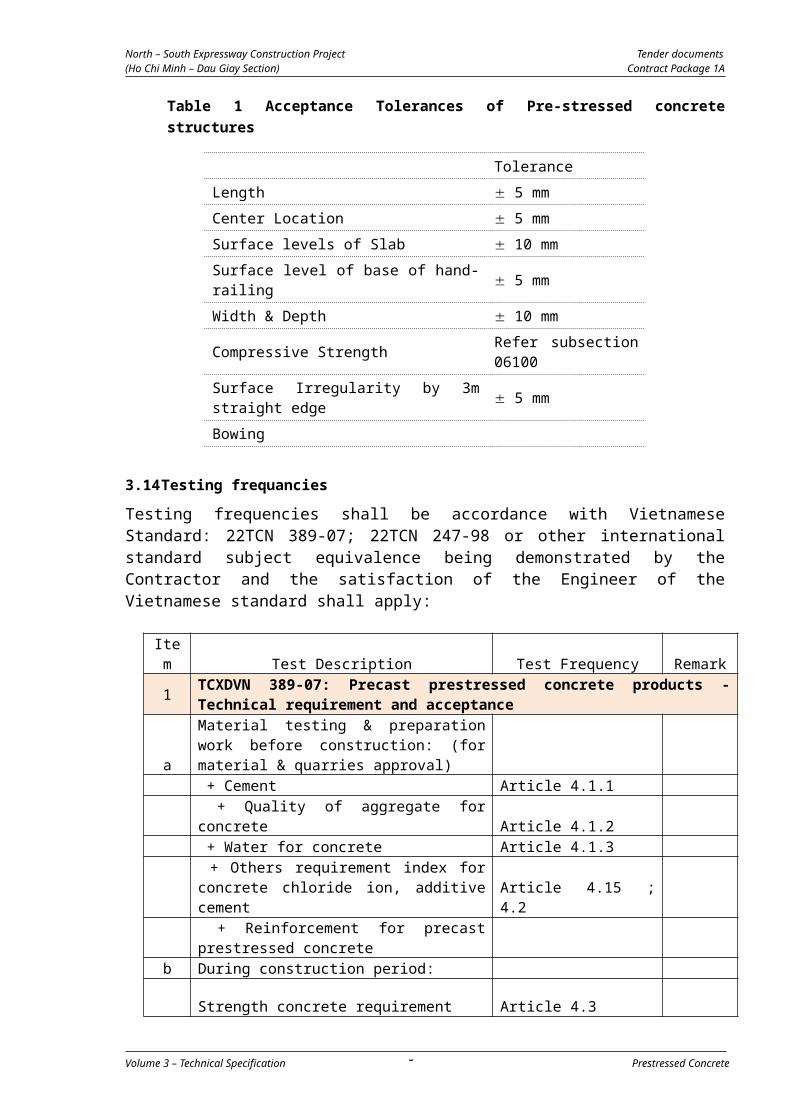
North – South Expressway Construction Projec Tender documents(Ho Chi Minh – Dau Giay Section) Contract Package 1A
3. ELASTOMERIC BEARINGS
3.1 General
(e) Elastomeric bearings shall consist of laminated elastomeric pads or
assemblies of laminated elastomeric pads as indicated on the
Drawings and as specified herein.
(f) Variation in thickness of an individual elastomer lamination shall not
exceed 3 mm within the width or length of a bearing pad and the
variation in thickness of all elastomer laminations within a bearing pad
shall be such that each metal or fabric lamination will not vary by
more than 3 mm from a plane parallel to the top or bottom surface of
the bearing pad.
(g) The total out to out thickness of a bearing pad shall not be less than
the thickness indicated on the Drawings nor more than 6 mm greater
than that thickness. Variation of total thickness within an individual
bearing pad shall not exceed 3 mm.
(h) The length and width of a bearing pad shall not vary more than 3 mm
from the dimensions indicated on the Drawings.
(i) The bond between the elastomer and the steel laminate shall be such
that, when a sample is tested for separation, failure shall occur within
the elastomer and not between the elastomer and the steel.
3.2 Materials
(a) All materials used in the manufacture of the bearing assemblies shall
be new and unused with no reclaimed material incorporated into the
finished assembly. All bonding of components shall be done under
heat and pressure during the vulcanizing process. The bond shall be
continuous throughout the plan area with no air spaces greater than
0.25 mm within the bonding material. The bearing assemblies shall be
furnished as complete units from one manufacturing source.
(b) The materials for the elastomeric bearings and assemblies shall
comply with the following requirements:
3.2.1 Elastomeric Materials
The elastomic materials of the compounds shall be 100% virgin polychloroprene
synthetic rubber meeting the requirements of Table No.1. The properties of the
elastomeric compounds shall be determined from test specimens complying with
ASTM D3182 through D3190 inclusive and D3192. A variation of 10% in tensile
strength and ultimate elongation under “physical properties” will be permitted
when test specimens are cut from the finished product.
Volume 3 – Technical Specification Waterproofing- 100
-
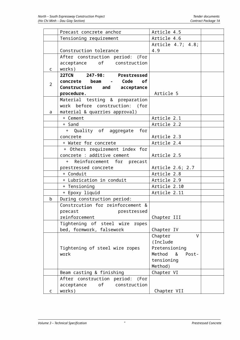
North – South Expressway Construction Projec Tender documents(Ho Chi Minh – Dau Giay Section) Contract Package 1A
3.2.2 Internal Steel Laminates
The internal steel laminates for the laminated elastomeric bearing pads shall be
rolled carbon steel sheets complying with ASTM A 570 or AASHTO N183 (ASTM
A36).
3.2.3 Laminated Elastomeric Bearing Pads
Laminated elastomeric bearing pads shall be individually molded to the required
size. Corners and edges may be rounded with a radius at the corners not
exceeding 9 mm and a radius at the edges not exceeding 6 mm. All edges of
the steel laminations shall be covered with not less than 4 mm and not more
than 6 mm of elastomer. The characteristics of the elastomeric bearing pads
shall be within the following listed tolerances:
TABLE No.1 - Requirements of Elastomeric Bearing Pads
ASTM Standard Physical Properties Value
D2240 Hardness, ASTM D2240 60 5D412 Tensile strength, min.kg/cm2
Ultimate elongation, min.%175425
Heat ResistanceChange in durometer hardness, max.points
+ 15
D573, 70 HR. @ 100oC
Change in tensile strength, max.% Change in ultimate elongation, max. %
- 15- 40
Compressive SetD395. Method B
22 hours @ 100 oC max. % 35
Ozone
D1149 100 pphm ozone in air by volume, 20% strain, 37.7 oC 1C, 100 hours mountingProcedure D 518, Procedure A
NoCracks
Adhesion to SteelBond made during vulcanization 80% R(Z1)
D429, A Bond Strength (per square cm) 2.8kgD429, B Peel Strength (per cm of width) 7 kg
Adhesion to TFEBond made during vulcanization
D429, B Peel Strength
Polychloroprene - Synthetic Rubber
ASTM Standard Physical Properties 60 DuroLow Temperature Test-Durometer ChangeBearing or sample to be exposed for 96 hrs. @-28 oC, 2 oC. (The specimen
Volume 3 – Technical Specification Waterproofing- 101
-

North – South Expressway Construction Projec Tender documents(Ho Chi Minh – Dau Giay Section) Contract Package 1A
shall have a 24 hr. conditioning period at room temperature prior to low temperature exposure). The durometer test shall be made at-28 oC on an unbuffed surface. Durometer hardness increase, Max. ASTM D2240, 30 second reading. Durometer to be placed in freezer with test specimen
+ 15(Z2)
D746 Brittleness temp., 3 min., at -40 oC No cracksStructural Steel. The internal steel laminates for the laminated elastomeric bearings shall be rolled mild steel sheets conforming to SAE 1020 or AASHTO M183.Laminated elastomeric bearings shall be individually molded to the required size. Corners and edges may be rounded with a radius at the corners not exceeding 9 mm and radius at the edges not exceeding 6 mm. All edges of the steel laminations shall be covered with not less than 3 mm and not more than 6 mm of elastomer. The dimensions of the elastomeric bearings shall be within the following listed tolerances:
Overall Vertical Rubber Dimension.Average total rubber thickness 32 mm or lessAverage total rubber thickness over 32 mm
-0, +3 mm
-0, +6 mm
Overall Horizontal Rubber Dimension90 cm or less 0, + 3 mm
Thickness of individual layers of elastomer (60 Durometer Only) 20%Variation from a plane parallel to the theoretical surface per 300 mm, tops 1.5 mm sides 6 mm Edge cover of embedded metallic laminate 4 mm min.
6 mm max.
The rubber laminates shall be of uniform integral units, capable of being
separated by mechanical means into separate, well-defined elastomeric layers.
The ultimate breakdown limit of the elastomeric bearing under compressive
loading shall be not less than 140 kgs/cm2. In addition to the requirements of
Table No. 1, the stress-strain relationship of the finished elastomeric bearings at
room temperature shall not exceed the following limitations.
CompressionStress 35 kgs/sq.cm 56 kgs./sq.cmStrain (Percent of total thickness of all elastomer laminations
5% 7%
Volume 3 – Technical Specification Waterproofing- 102
-

North – South Expressway Construction Projec Tender documents(Ho Chi Minh – Dau Giay Section) Contract Package 1A
(c) In addition, shear resistance of the bearing shall not exceed 2.1
kg/cm2 for 60 durometer, Table No. 1 compounds at 25% strain of the
total effective rubber thickness after an extended four-day ambient
temperature of -28 oC.
(d) The Contractor shall furnish to the Engineer a certification by the
manufacturer that the elastomer, in the elastomeric bearing pads to
be furnished conforms to all of the above requirements. The
certification shall be supported by a certified copy of the results of
tests performed by the manufacturer upon samples of the elastomer
to be used in the pads.
4. MECHANICAL BEARINGS
(a) Mechanical Bearings shall be pot type bearings. Movement bearings
will normally have sliding surfaces of stainless steel and
polytetrafluorethylene and may also have been fitted with guide bars
or keyways.
(b) Bearings shall have surface protecting in accordance with
requirements and procedures noted under Specification section
08800.
4.1 Packaging, Handling, and Storage of Mechanical Bearings
(a) Prior to shipment from the point of manufacture, bearings shall be
packaged in such a manner to ensure that during shipment and
storage the bearings will be protected against damage form handling,
weather, or any normal hazard.
(b) Each completed bearing shall have its components clearly identified,
be securely bolted, strapped or otherwise fastened to prevent any
relative movement, and marked on its top as to location and
orientation in each structure in the project in conformity with the
plans.
(c) Dismantling at the site shall not be done unless absolutely necessary
for inspection or installation.
(d) All bearing devices and components shall be stored at the work site in
an area that provides protection form environmental and physical
damage.
(e) When installed, bearings shall be clean and free of all foreign
substances.
Volume 3 – Technical Specification Waterproofing- 103
-
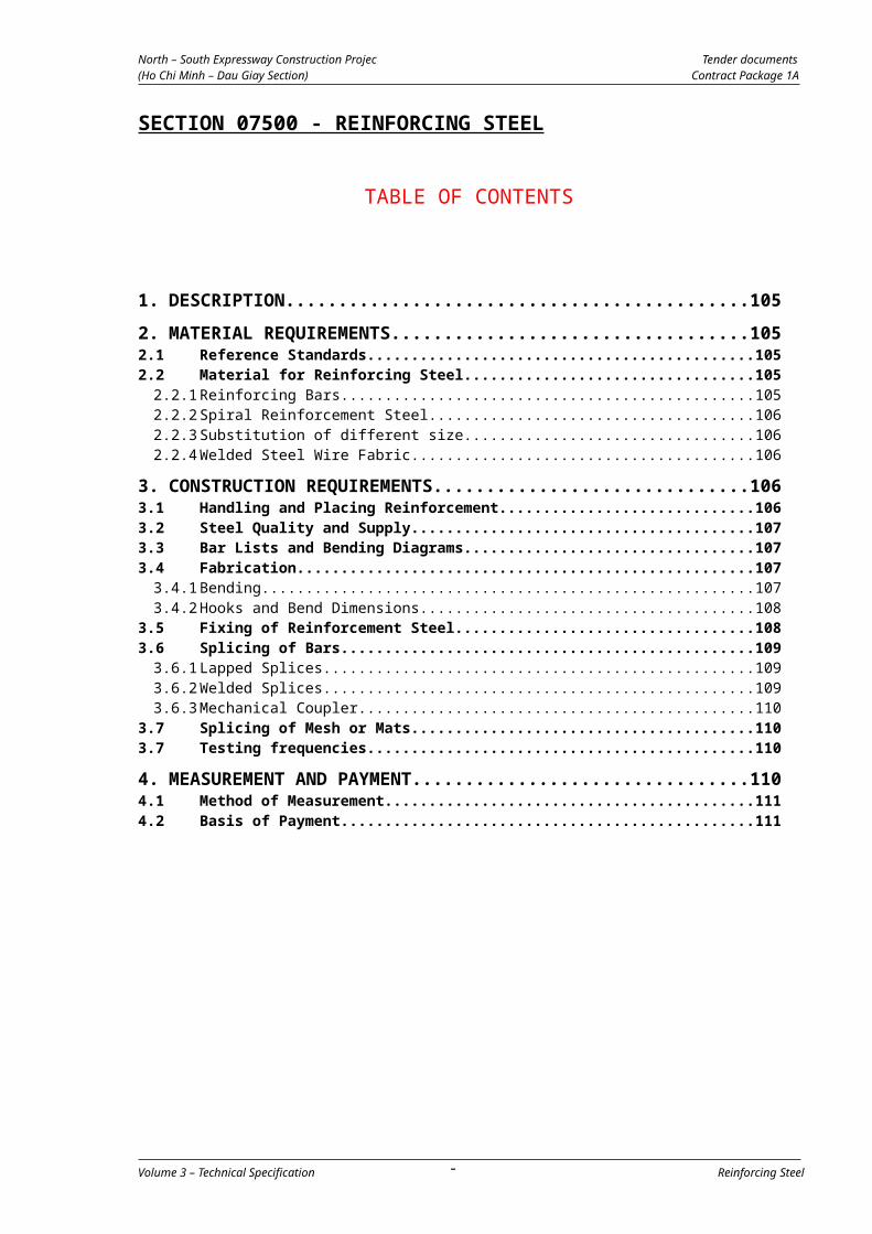
North – South Expressway Construction Projec Tender documents(Ho Chi Minh – Dau Giay Section) Contract Package 1A
5. DOWELS
(a) Steel dowels shall be provided and installed in accordance with
requirements and with accessories noted on the drawings.
(b) Dowels shall be smooth plain billet-steel bars conforming to
requirements of ASTM A615, 400 MPa and shall be zinc (hot-dip
galvanized) in accordance with ASTM A123.
(c) Dowels may be cast-insitu as shown on the drawings or drilled and
grouted with an approved epoxy compound.
(d) If dowels are drilled and grouted:
holes shall provide at least 10 mm in diameter greater than the largest diameter of the dowel;
holes shall be thoroughly cleaned with compressed air and water prior to grouting of dowels so as to remove all loose or extraneous materials;
the epoxy compound used shall be ASTM C881, Type IV or approved equivalent and mixed and placed in accordance with manufacture’s requirements.
6. BEARING INSTALLATION
(a) The bearings shall be clearly marked with their longitudinal and
transverse axes, their type number and their intended locations in the
Works.
(b) Unless otherwise approved by the Engineer bearing beds shall be of
non-shrink grout conforming to ASTM C1107, Grade A. Proposals for
the thickness and type of bearing plinths and beds shall be submitted
by the Contractor and approved by the Engineer in advance of
bearing installation.
(c) Bearings shall not be dismantled. Any transit bolts, straps or other
temporary fixing shall not be removed until the bearing is fixed in its
final position and the structure immediately above the bearing is in
place. Care shall be taken to ensure that all transit bolts, straps or
other temporary fixings are finally removed.
(d) All bearings shall be set horizontal in both directions and shall be
positioned so that the inscribed longitudinal axis is parallel to the
structure axis at the point of support, unless otherwise noted on the
Drawings.
(e) Any devices such as steel packs used to hold bearings level whilst
being fixed, must be removed so that the bearing seats only on its
mortar bedding.
(f) Where pre-cast beams and segments are placed on elastomeric
Volume 3 – Technical Specification Waterproofing- 104
-
North – South Expressway Construction Projec Tender documents(Ho Chi Minh – Dau Giay Section) Contract Package 1A
bearings, immediately prior to the placing of each beam and segment
the top of the bearing shall be coated with a sufficient thickness of
approved mortar to take up any irregularities between the surface of
the beams and segment and the bearings.
(g) The characteristics of all bearing shall be within the Manufacturer’s
tolerances and to the following tolerances:
Alignment, maximum departure from required vertical or horizontal
plane:
Entire assembly 1:400
Lower part of bearing 1:1000 relative to upper
Plan position
Laterally 3mm
Longitudinally 6mm
Center/Center Spacing 3mm
7. TESTING OF BEARINGS
The testing of selected bearings shall be arranged with the Engineer prior to
their inclusion in the Works. The testing shall be done at an independent
testing facility approved by the Engineer.
7.1 Mechanical Bearing Tests
(1) Vertical Proof Load Test of Complete Bearing
The vertical proof load shall be 1.5 times the maximum vertical load
specified in the bearing schedule. The proof load shall be maintained
for a minimum period of three minutes.
(2) Horizontal Proof Load Test of Complete Bearing
Bearings, which are required to resist lateral forces, shall be further
tested to 1.5 times the lateral load stated on the Drawings while
loaded in compression to the minimum vertical load shown on the
Drawings. The load shall be maintained for three minutes.
(3) Rotation test of Complete Bearing
(a) The bearings shall be tested in rotation to the value for rotation
shown on the Drawings while being loaded in compression to the
maximum vertical load shown on the Drawings. Bearings, which
are required to resist lateral forces, shall also have the specified
lateral load stated on the Drawings applied during this test.
(b) The direction of application of the lateral load and the axis of
rotation shall be compatible with the in-service loads and
Volume 3 – Technical Specification Waterproofing- 105
-

North – South Expressway Construction Projec Tender documents(Ho Chi Minh – Dau Giay Section) Contract Package 1A
rotational requirements. The lateral load shall be applied using a
calibrated sliding surface to minimize any frictional restraint. All
PTFE and stainless steel interfaces shall be lubricated prior to the
test. The test loads shall be maintained for three minutes.
7.2 Elastomeric Bearings
(1) Long-Duration Compression Tests on Bearings
Selected bearings shall be loaded in compression to 1.5 times their
maximum design load for a minimum period of 15 hours. If, during
the test, the load falls below 1.3 times the maximum design load, the
test duration shall be extended by the period of time for which the
load is below this limit. The bearing shall be examined visually at the
end of the test while it is still under load. If the bulging pattern
suggests laminate parallelism or a layer thickness that is outside the
specified tolerances, or poor laminate bond, the bearing shall be
rejected. If there are three or more separate surface cracks that are
greater than 0.08 in. (2mm) wide and 0.08 in. (2mm) deep, the
bearing shall be rejected.
(2) Shear Modules Tests on Material from Bearings
The shear modulus of the material in the finished bearing will be
evaluated by testing a specimen cut from the bearing using the
apparatus and procedure described in Annex-A of ASTM D4014, or, at
the discretion of the Engineer, a comparable non-destructive stiffness
test may be conducted on a pair of finished bearings. The shear
modulus shall fall within 15 percent of the specified value or within the
range for its hardness given in AASHTO Standard Specifications for
Highway Bridges, Article 14.3 of Division I, if no shear modulus is
specified. If the test is conducted on finished bearings, the material
shear modulus shall be computed from the measured shear stiffness
of the bearings, taking due account of the influence on shear stiffness
of bearing geometry and compressive load.
7.3 Rejection of Bearings
Any bearing that, as a result of the testing specified, exhibits any signs of
failure such as:
(a) Splitting or permanent deformation of the elastomer;
(b) Tearing, cracking or permanent deformation of the PTFE sliding
surface;
(c) Cracking or permanent deformation of the sealing ring or other part
of the bearing;
(d) Abrasive marks indicating abnormal contact between the metal
surfaces of the bearing plates or piston, and the pot;
Volume 3 – Technical Specification Waterproofing- 106
-

North – South Expressway Construction Projec Tender documents(Ho Chi Minh – Dau Giay Section) Contract Package 1A
(e) or does not comply with the requirements and tolerances of this
Specification Section, shall be rejected and shall be replaced
immediately.
(f) Bearings damaged during transport, installation or subsequent
construction operations shall also be liable for rejection and
replacement.
8. MEASUREMENT AND PAYMENT
8.1 Method of Measurement
(a) The bearings shall be measured for payment by the number of each
type completed in place in accordance with the drawings, and
approved by the Engineer.
(b) Galvanized steel dowels installed and approved by the Engineer shall
not be measured separately.
8.2 Basis of Payment
(a) The accepted quantities, measured as provided above, shall be paid at
the contract price per unit of measurement for the pay items of Bill of
Quantities listed below.
(b) Payment shall be full compensation for the work prescribed in this
Section for the supply, bearing testing, fabrication, transport, coating
and placing of all materials, and for furnishing all labour, materials,
tests, tools, equipment and any incidentals to complete the work as
shown on the Drawings and as required by these Specifications, and/or
as directed by the Engineer. Payment shall also include full
compensation for bearing bedding and furnishing, fabricating,
transporting, coating and placing all galvanized steel dowel bars with
epoxy grout and proper placement of dowels and grout.
Pay Item Description Unit
07600-01 Bearing Elastomeric Type (600 350
78) mm
set
07600-02
07600-03
Pot Bearing, bearing capacity 2000 KN
Non-shrinkage mortar
Set
Cu.m
07600-05 Bearing pad steel 2mm Ton
07600-06
07600-07
Set up elastic layer whole thickness is 2cm
Bitument
Sq.m
Cu.m
SECTION 07700 - WATERPROOFING
Volume 3 – Technical Specification Waterproofing- 107
-

North – South Expressway Construction Projec Tender documents(Ho Chi Minh – Dau Giay Section) Contract Package 1A
TABLE OF CONTENTS
1. DESCRIPTION..................................................................109
2. MATERIAL REQUIREMENTS...............................................1092.1 Reference Standards...................................................................1092.2 Deck Waterproofing Membrane....................................................1092.3 Bituminous Waterproofing Membrane...........................................1092.4 Submittals..................................................................................110
3. CONSTRUCTION REQUIREMENTS......................................1103.1 Product Delivery, Storage and Handling........................................1103.2 Preparation of Surface.................................................................1103.3 Application..................................................................................110
3.3.1 Deck Waterproofing Membrane.....................................................................1103.3.2 Bituminous Waterproofing Membrane...........................................................111
4. MEASUREMENT AND PAYMENT.........................................1114.1 Method of Measurement..............................................................1114.2 Basis of Payment.........................................................................111
Volume 3 – Technical Specification Waterproofing- 108
-

North – South Expressway Construction Projec Tender documents(Ho Chi Minh – Dau Giay Section) Contract Package 1A
1. DESCRIPTION
The work under this Specification Section consists of the supply, transport
and installation of waterproofing membranes in accordance with the
information, procedures and details stated in this Specification Section and in
conformance with the drawings, and as required by the Engineer.
The Contractor shall apply bituminous membranes and deck waterproofing
membranes to all surfaces as indicated on the drawings, including but not
limited to wing walls, retaining walls, abutment walls, and similar
foundations, and to the bridge decks.
2. MATERIAL REQUIREMENTS
2.1 Reference Standards
The following Standards in their latest edition shall be particularly applied to
the works covered by this Specification Section.
AASHTO
M243
Field Applied Coating of Corrugated Metal Structural
Plate for Pipe, Pipe Arches, and Arches
ASTM D41-05Asphalt Primer Used in Roofing, Damp proofing, and
Waterproofing
ASTM D173-
03
Bitumen Saturated Cotton Fabrics Used in Roofing and
Waterproofing
ASTM D449-
03
(Type III) Standard Specification for Asphalt Used in
Damp proofing and Waterproofing
ASTM D517-
98
(2003)
Standard Specification for Asphalt Plank
2.2 Deck Waterproofing Membrane
All the materials to be used for furnishing and installing the deck
waterproofing membrane shall be certified by the manufacturer and shall be
approved by the Engineer before they are used in the Works.
2.3 Bituminous Waterproofing Membrane
(a) The Contractor shall furnish to the Engineer certification from the
manufacturer that the bituminous waterproofing membrane system
has been used successfully in similar applications during the
preceding five years.
(b) The Contractor shall provide to the Engineer evidence that the applier
of the material is a qualified, experienced applier and is approved by
the manufacturer to apply his materials.
(c) Primer: The furnished primer material shall be in accordance with
ASTM-D41, or as approved by the Engineer.
(d) Mastic: The furnished primer material shall be in accordance with
Volume 3 – Technical Specification Waterproofing- 109
-

North – South Expressway Construction Projec Tender documents(Ho Chi Minh – Dau Giay Section) Contract Package 1A
AASHTO-M243, as applicable and as approved by the Engineer.
(e) Asphalt: Asphalt for mop coat shall be in accordance with ASTM D449,
Type III.
(f) Waterproofing fabric: Asphalt saturated fabric shall be in accordance
with ASTM D173.
(g) Asphalt plank: Material for asphalt plank, if used or if approved by the
Engineer, shall be in accordance with ASTM D517.
2.4 Submittals
The Contractor shall submit to the Engineer three samples of each type of
the materials he proposes to use in accordance with pertinent requirements
of the Specifications.
For bituminous mastic and primer, one-pint containers shall be submitted.
The Contractor shall submit to the Engineer certification that materials to be
provided comply with the requirements of this specification.
3. CONSTRUCTION REQUIREMENTS
3.1 Product Delivery, Storage and Handling
(a) The Contractor shall deliver products to the job site in their original
unopened containers clearly labelled with the manufacturer’s name,
brand designation, type and class as applicable.
(b) The Contractor shall store products in an approved dry area and shall
protect them from contact with soil and from exposure to the elements.
Products shall be kept dry at all times.
(c) Products shall be handled in a manner that will prevent breakage of
containers and damage to products.
3.2 Preparation of Surface
(a) The surface to which the waterproofing is to be applied shall be
cleaned of all loose and foreign materials, dirt, grease or oil and shall
be dry. When necessary the Engineer may require the surface to be
scrubbed with water and a stiff brush, after which the surface shall be
allowed to dry before application of the primer.
(b) Concrete to which the deck waterproofing membrane is to be applied
shall be prepared in accordance with the manufacturer’s
recommendations.
3.3 Application
3.3.1 Deck Waterproofing Membrane
The deck waterproofing membrane shall be a proprietary waterproofing
system of the thickness indicated on the drawings and as approved by the
Engineer, and shall be applied in accordance with the manufacturer’s
recommendations.
Volume 3 – Technical Specification Waterproofing- 110
-

North – South Expressway Construction Projec Tender documents(Ho Chi Minh – Dau Giay Section) Contract Package 1A
3.3.2 Bituminous Waterproofing Membrane
The Contractor shall furnish and install the bituminous membrane as
specified herein to all surfaces indicated on the Drawings including, but
not limited to, abutment, wing-walls, retaining walls, and similar
foundations where directed by the Engineer. The work shall include the
supply and application of bituminous membranes on all surfaces specified
to receive waterproof membrane.
Concrete or other surfaces, which are to be protected by bituminous
membrane, shall be thoroughly cleaned before the primer is applied.
They shall then be brush or spray painted with two coats of tar or asphalt
primer for absorptive treatment. Below ground not less than two coats
shall be applied at a rate of 0.56 liters per square meter of surface.
On the well-primed surface one application of tar or asphalt seal coat shall
be applied by brush at a rate of 0.45 liters per square meter. Care shall be
taken to confine all paints to the areas to be waterproofed and to prevent
disfigurement of any other parts of the structure by dripping or spreading
of the tar or asphalt.
4. MEASUREMENT AND PAYMENT
4.1 Method of Measurement
(a) Deck waterproofing membranes shall be measured for payment by
square meters actually completed in place in accordance with the
Drawings.
(b) No measurement and payment shall be made for bituminous
membranes applied on other concrete structures. All costs associated
with this work shall be considered as a subsidiary obligation and
requirement under the applicable concrete pay items in the Bill of
Quantities.
4.2 Basis of Payment
(a) The accepted quantities, measured as provided above, shall be paid at
the contract price per unit of measurement for the pay items of the
Bill of Quantities listed below.
(b) Payment shall be full compensation for the work prescribed in this
Section for the supply and installation of all the required membranes
for waterproofing including all labour, materials, tests, tools,
equipment and any incidentals to complete the work as shown on the
Drawings and as required by these Specifications, and/or as directed
by the Engineer.
Pay Item Description Unit
07700 - 01 Waterproofing Membrane m2
Volume 3 – Technical Specification Waterproofing- 111
-

North – South Expressway Construction Projec Tender documents(Ho Chi Minh – Dau Giay Section) Contract Package 1A
SECTION 07800 - EXPANSION JOINT
TABLE OF CONTENTS
1. DESCRIPTION..................................................................113
2. MATERIAL REQUIREMENTS...............................................1132.1 Reference Standards...................................................................1132.2 Submittals..................................................................................1162.3 Approval of Materials..................................................................116
3. CONSTRUCTION REQUIREMENTS......................................1163.1 Method of Construction and Installation.......................................1163.2 Pre-moulded Joint Filler...............................................................1173.3 Joint Sealer.................................................................................117
4. MEASUREMENT AND PAYMENT.........................................1184.1 Method of Measurement..............................................................1184.2 Basis of Payment.........................................................................118
Volume 3 – Technical Specification Expansion joint- 112 -
–
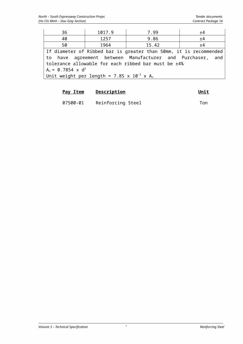
North – South Expressway Construction Projec Tender documents(Ho Chi Minh – Dau Giay Section) Contract Package 1A
1. DESCRIPTION
This Specification Section describes the requirements for expansion and
fixed joints as indicated on the drawings, including pre-moulded joint filler
and joint sealer. The Contractor shall furnish all required materials and
install expansion joints, fixed joints, pre-moulded joint filler and joint sealer
in accordance with the details indicated on the drawings and as specified
herein. This work shall include the supply and installation or application of
all necessary hardware including anchor bolts and studs, sealants,
adhesives, epoxies, and other accessories.
2. MATERIAL REQUIREMENTS
2.1 Reference Standards
The following Standards in their latest edition shall be particularly applied
to the works covered by this Specification Section.
AASHTO M297 Specification standard for Bridge expansion
jointAASHTO M183
ASTM A123Zinc (Hot-Dip Galvanized) Coatings on Iron and Steel Products
ASTM D395 Rubber Property—Compression Set
ASTM D412Vulcanized Rubber and Thermoplastic Rubbers and Thermoplastic Elastomer - Tension
ASTM D471 Rubber Property - Effect of Liquids
ASTM D994Preformed Expansion Joint Filler for Concrete (Bituminous Type)
ASTM D1149Rubber Deterioration - Surface Ozone Cracking in a Chamber
ASTM D2240 Rubber Property - Durometer Hardness
ASTM D6690Joint and Crack Sealants, Hot Applied, for Concrete and Asphalt Pavements
(a) The elastomeric portion of the expansion joints shall be of the
compound known as neoprene which shall have the physical
properties as determined by the following ASTM requirements:
Standard Physical Properties Requirements
ASTM D412 Tensile strength 126kg/cm2 (min. )
ASTM D412 Elongation at break 400%
ASTM D2240 Hardness (Durometer A) 50 5
ASTM D395 Compression set(Method B) 22 hours at 70 oC
20%, max.
ASTM D1149 Ozone resistance: No cracks
Volume 3 – Technical Specification Expansion joint- 113 -
–

North – South Expressway Construction Projec Tender documents(Ho Chi Minh – Dau Giay Section) Contract Package 1A
Exposure to 100 ppm ozone for 70 hours @ 38°C sample under 20% strain
ASTM D471 Oil deterioration:Volume increase after immersion in ASTM Oil # 3 for 70 hours @ 100 °C
120%, max.
(b) The dimensions of the neoprene portion of the joint shall be correct
to zero millimeters under and plus 6-mm over in width and length,
and from zero millimeters under to plus 3-mm in thickness of the
exterior dimensions required on the drawings, measured at 21oC.
(c) The sealant for sealing joints between the expansion joint units,
along the edges of the expansion joint, and the bolts and plugs shall
be a high solid, one-part polyurethane based sealant that cures
quickly, without shrinkage, into a rubber with high elongation
characteristics and excellent recovery. Sealant shall be capable of
bonding to concrete, steel, and neoprene without the use of a
primer. When cured, the sealant shall possess excellent abrasion
resistance and shall resist attack by salt, oil, and road chemicals.
The sealant to be used shall meet the requirements of the
manufacturer of the neoprene expansion joint.
(d) When test specimens are cut from the finished product a 10-percent
variation in Physical Properties will be allowed.
(e) The flexible epoxy for filling voids around the nut fasteners shall
consist of a black two-component flexible epoxy sealant having the
following physical properties:
Base Material: Flexibilized Epoxy Resin
Weight/Liter(mixed materials):
1.05 kg/liter
Mixing Time: 2 min. @ 24°C with 50 strokes minimum
Pot Life: 10-15 minutes @ 24°C
Initial Cure: 4 hours @ 24°C
Final Cure: 48 hours @ 24°C
Shelf Life: 12 months minimum (components separate)
Hardness Shore A Durometer:
80 + 10
(f) Flexible epoxy shall be supplied either in cans or preassembled
cartridges. Flexible epoxy shall meet the requirements of the
manufacturer of the expansion joint. Flexible epoxy shall also be
compatible with and have the physical characteristics when cured,
similar to the neoprene of the joint.
(g) The adhesive/sealant bedding epoxy for bonding the expansion joint
Volume 3 – Technical Specification Expansion joint- 114 -
–

North – South Expressway Construction Projec Tender documents(Ho Chi Minh – Dau Giay Section) Contract Package 1A
to concrete or steel shall be supplied in pre-measured cartridges or
cans and shall consist of a grey, two-component flexible epoxy
having the following physical properties:
Base Material: Epoxy Resin
Color: Concrete Grey
Weight/Liter (Mixed Materials):
1.44 kg/liter
% Solids Content: 98 % minimum by weight
Mixing Time: 2 min. @ 24 ºC with 50 strokes minimum
Pot Life: 25-30 minutes @ 24°C
Initial Cure: 4 hours @ 24°C
Final Cure: 48 hours @ 24 ºC
Shelf Life: 12 months minimum (components separate)
Tensile Strength: 211 kg/cm2
Elongation: 7% @ 24 °C
Water Absorption: 1. 0% maximum
Bond Strength to concrete: Concrete fails before bond
(h) Structural steel anchors shall be fabricated and hot dip galvanized in
accordance with the requirements of ASTM A123.
(i) Anchor bolts for joint seals shall be hot dip galvanized in accordance
with ASTM A153 commercial grade bolts set in epoxy mortar in holes
cored in the deck in accordance with approved shop drawings.
(j) The surface of holes cored in the concrete shall be carefully
prepared to provide a cleaned textured surface to which the epoxy
mortar can successfully bond. Faces shall be mechanically tooled
until surface glaze and contamination have been removed; dusted
to remove all residues; dried thoroughly and then primed with
hydrophobic epoxy resin immediately prior to setting the anchor
bolts in epoxy mortar. Bolts shall be degreased with white spirit
alcohol and dried thoroughly. Coring and setting the anchor bolts
shall not be done until a minimum of 7 days after concrete is
poured.
(k) Epoxy mortar shall consist of a mixture of aggregate and epoxy
binder. Aggregate shall consist of clean, hard quartzite particles
with a maximum size of 2 millimeters. Aggregate shall be dried
until the moisture content is less than 0.2 percent by weight and
then shall be sealed in plastic containers until required for mixing on
site. Binder for epoxy mortar shall be two part, cold curing,
solventless epoxy produced by an approved manufacturer. Primer
shall be compatible with the epoxy resin binder and shall be
supplied by the same manufacturer. The type of resin selected shall
Volume 3 – Technical Specification Expansion joint- 115 -
–

North – South Expressway Construction Projec Tender documents(Ho Chi Minh – Dau Giay Section) Contract Package 1A
be that recommended by the manufacturer for this application and
shall meet the requirements of the supplier of the component on
which it is to be used.
(l) Components of the epoxies shall be proportioned, mixed, applied and
cured strictly in accordance with the manufacturer’s printed
recommendations. Mixing shall be carried out with an efficient
mechanical device which ensures that all components are fully
dispersed and wetted. The two parts of the epoxy binder for the
mortar shall be thoroughly mixed first without frothing and the
aggregate added progressively. Mixed epoxy mortar which has begun
to cure before it has been placed and compacted, will be rejected and
a fresh batch shall be mixed.
2.2 Submittals
(a) The Contractor shall submit to the Engineer, for his approval,
complete Shop Drawings of all expansion joints. The Shop Drawings
shall include a movement chart showing the total anticipated
movement of the structure and the required setting width of the
joint assembly at various temperatures. All movements due to
shrinkage, creep, mid-slab deflection, and similar data, may not be
incorporated into this chart but shall be considered by the
Contractor and approved by the Engineer prior to final installation
and adjustment.
(b) The Contractor shall provide to the Engineer for review and
approval manufacturer’s literature verifying that all materials to be
supplied conform to the requirements of these specifications.
(c) The Engineer may request the Contractor to furnish whatever
samples which may be required to perform any of the tests specified
as necessary to approve the material. The use of all joints to be
used in the work shall be subject to approval of the Engineer.
2.3 Approval of Materials
No materials shall be used or installed until they have been approved by
the Engineer.
3. CONSTRUCTION REQUIREMENTS
3.1 Method of Construction and Installation
(a) The Contractor shall obtain installation instructions from the supplier
of the expansion joint material and comply with the instructions
provided for the installation of the joint. The adequacy of the joint
design and installation details shall be subject to the approval of
the Engineer. The Contractor shall obtain the technical assistance of
a field representative from the manufacturer of the joint during its
installation. Proper adjustment shall be made for temperature at
Volume 3 – Technical Specification Expansion joint- 116 -
–

North – South Expressway Construction Projec Tender documents(Ho Chi Minh – Dau Giay Section) Contract Package 1A
the time of installation.
(b) Concrete on which expansion joints are to be set shall be dry, clean
and free from dirt, grease, latency and contaminants; level and
sound with no broken or spilled concrete. No joint shall be placed
until the Engineer has inspected and approved the seat conditions.
(c) After coating the seat area with the specified sealant adhesive, the
joint shall be positioned over the anchor bolts and the nuts securely
tightened. All loose or long anchor bolts shall be corrected in a
manner approved by the Engineer.
(d) All joints between units, around connecting bolts, and cavity plugs
shall be carefully sealed with sealant in a neat workmanlike manner
to keep out water and protect against corrosion. Neoprene surfaces
to be in contact with sealant shall be buffed at the plant or wire
brushed prior to installation to provide a bonding surface for the
sealant.
(e) Prior to filling the space in the bolt wells, the Engineer shall inspect
the anchor bolts and the tightening of the nuts to the
manufacturer’s specified torque. Any wells sealed without the
Engineer’s approval shall be opened and resealed after approval at
the Contractor’s expense.
(f) The finished joint shall present a smooth, neat appearance with no
protruding bolts or rough joints. Excess sealant shall be wiped or
scraped away before it becomes hard.
3.2 Pre-moulded Joint Filler
(a) Pre-moulded joint filler shall conform to the requirements of ASTM
D994 with a nominal thickness of 20 mm. Joint filler must be
compatible with joint sealant.
(b) The filler for each joint shall be furnished in a single piece for the full
depth and width required for the joint. When the use of more than
one piece is required for a joint, the abutting ends shall be fastened
securely and held accurately to shape by stapling or other positive
fastening means.
3.3 Joint Sealer
(a) Joint sealer shall be in accordance with ASTM D6690.
(b) Each lot or batch of sealing compound shall be delivered to the job
site in the manufacturer's original sealed container. Each container
shall be marked with the manufacturer's name, batch or lot number,
and the safe heating temperature and shall be accompanied by the
manufacturer's certification stating that the compound meets the
requirements of this specification.
Volume 3 – Technical Specification Expansion joint- 117 -
–

North – South Expressway Construction Projec Tender documents(Ho Chi Minh – Dau Giay Section) Contract Package 1A
4. MEASUREMENT AND PAYMENT
4.1 Method of Measurement
(a) Expansion Joints shall be measured for payment by linear meters of
the material installed and approved by the Engineer, measured
along the centre line of the joint.
(b) The length of the expansion joint shall be in accordance with the
drawings or as shown on the Shop Drawings.
4.2 Basis of Payment
(a) Payment for Item Expansion Joints shall be made in accordance with
the applicable unit prices of the pay items of the Bill of Quantities
listed below,
(b) Payment shall be full compensation for all materials, labour, tools,
equipment and appurtenances and execution of all work and any
incidentals required for the complete finishing and installation of all
the respective expansion joint items.
(c) Pre-moulded Joint Filler and Joint Sealer shall not be paid separately.
They shall be deemed to be included in the unit price of Expansion
Joint with full compensation for all materials, labour, tools,
equipment and appurtenances and execution of all work and any
incidentals required for the complete finishing and installation of
pre-moulded joint filler and joint sealer.
Pay Item
Description Unit
07800-01 Expansion joint lm
Volume 3 – Technical Specification Expansion joint- 118 -
–

North – South Expressway Construction Projec Tender documents(Ho Chi Minh – Dau Giay Section) Contract Package 1A
Volume 3 – Technical Specification Expansion joint- 119 -
–
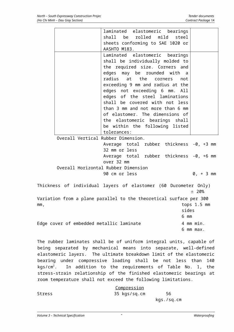
North – South Expressway Construction Projec Tender documents(Ho Chi Minh – Dau Giay Section) Contract Package 1A
SECTION 07900 - BRIDGE DRAINAGE
TABLE OF CONTENTS
1. DESCRIPTION..................................................................121
2. MATERIAL REQUIREMENTS...............................................1212.1 Reference Standards...................................................................1212.2 Drain Pipes.................................................................................1212.3 Catch pit and Grating...................................................................1212.4 Fixing Brackets............................................................................1212.5 Submittals..................................................................................1212.6 Delivery, Storage and Handling....................................................1212.7 Installation..................................................................................122
3. MEASUREMENT AND PAYMENT.........................................1223.1 Method of Measurement..............................................................122
3.1.1 Catch pits and gratings.................................................................................1223.1.2 Drainage Pipe................................................................................................1223.1.3 Basis of Payment...........................................................................................122
Volume 3 – Technical Specification Bridge drainage- 120
-
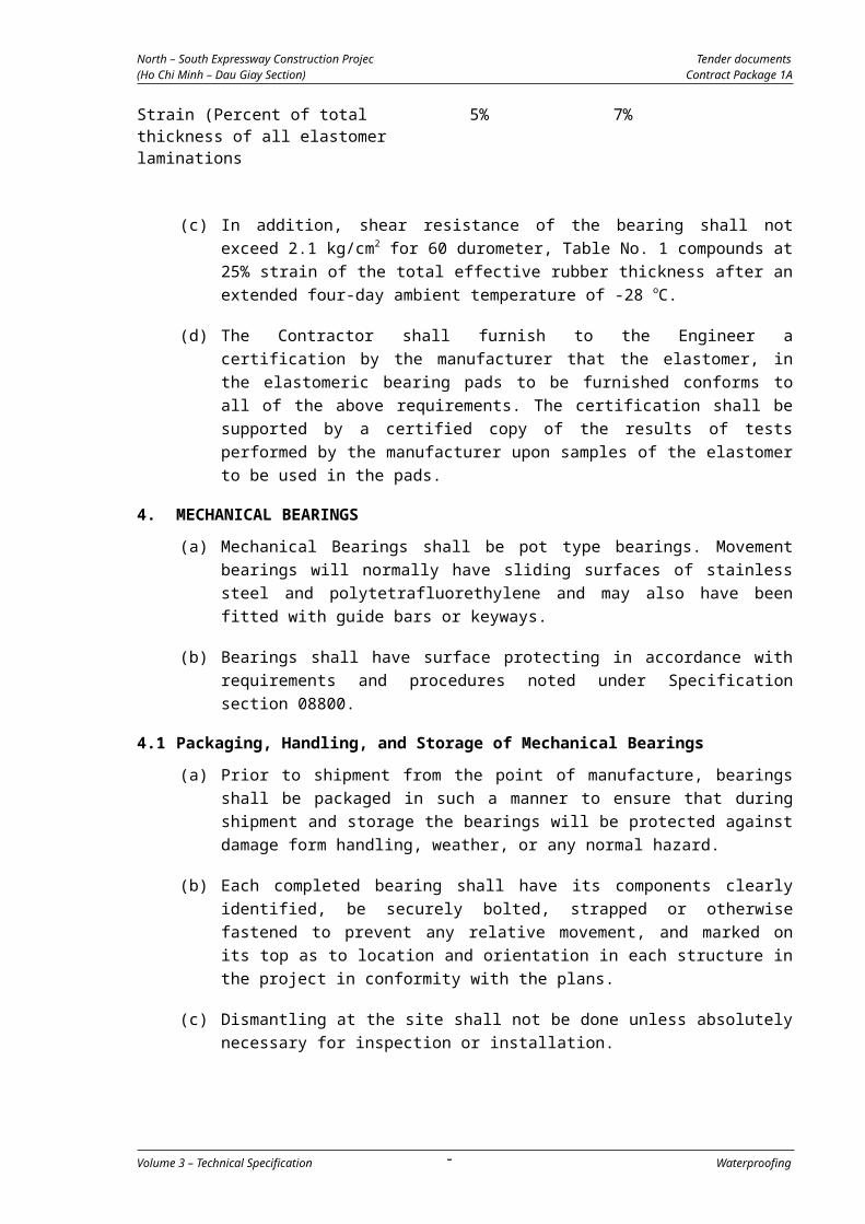
North – South Expressway Construction Projec Tender documents(Ho Chi Minh – Dau Giay Section) Contract Package 1A
1. DESCRIPTION
This work consists of the provision and installation of the bridge drainage
system. Work shall be in accordance with the drawings subject to the approval
of the Engineer.
2. MATERIAL REQUIREMENTS
2.1 Reference Standards
The following Standards in their latest edition shall be particularly applied to
the works covered by this Specification Section.
ASTM A53 Specification for pipe, steel, black and hot-dipped, zinc coated, welded and seamless.
ASTM A48 Specification for grey iron castings. JIS G 5501 Grey Iron Castings. JIS G 3442 Galvanised steel pipes for ordinary piping. JIS G 3101 Rolled steels for general structures
2.2 Drain Pipes
Pipe and fittings shall be of the size and types indicated on the drawings. They
shall be galvanized and comply with the requirements ASTM A53.
2.3 Catch pit and Grating
Catch pits and gratings shall be Gray Iron Casting with reliability test greater
than grade 50 as required by AASHTO A48 for heavy items, of the shape and
size and with the connection requirements as indicated on the drawings.
2.4 Fixing Brackets
The materials for fixing brackets shall conform to JIS G 3101, SS400, or equivalent standards and shall be galvanized or of other rust-resistance materials to the approval of the Engineer.
2.5 Submittals
The Contractor shall submit his method statement to the Engineer for his
approval. The method statement shall include but no be limited to
arrangements and details of pipes fittings and joints, means of casting the
catch pit into the structure and details of fixing pipe brackets to concrete
surfaces.
The Contractor shall submit to the Engineer for his approval manufacturer’s
certificates confirming that all materials meet the requirements of the relevant
standards and specifications. Certificates are required for pipes and all pipe
fittings and the catch pit and grating.
2.6 Delivery, Storage and Handling
Materials delivered to site shall be inspected for damage, unloaded, and stored
with the minimum handling. Materials shall be handled in such a manner as to
ensure delivery to storage or the point of installation in sound undamaged
condition. Pipes shall be carried and not dragged. Materials shall not be stored
Volume 3 – Technical Specification Bridge drainage- 121
-
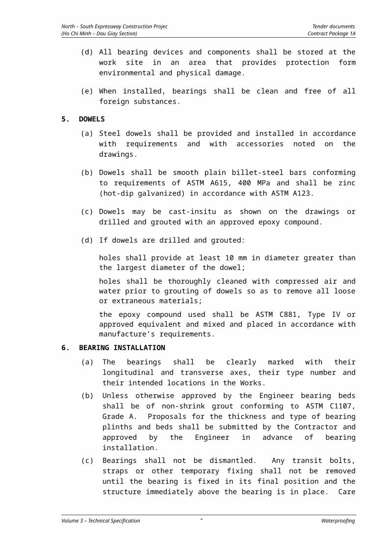
North – South Expressway Construction Projec Tender documents(Ho Chi Minh – Dau Giay Section) Contract Package 1A
directly on the ground. The inside of pipes and fittings shall be kept free of
dirt and debris.
2.7 Installation
Drainage catch pits and gratings shall be installed complete at the locations
indicated on the drawings. Catch pits shall be cast into the structure or cast
into a previously formed box out as detailed in the Contractor’s method
statement. Where the catch pits are to be cast into a box out all relevant
details shall be subject to the approval of the Engineer. Where catch pits are
secured into box outs using concrete, the concrete shall be at least equal in
strength to the concrete in the surrounding structure and all box out faces
shall be prepared as required for construction joints. The inside faces of the
catch pit shall be painted in accordance with specification 08800 – Painting
table 1, system for aggressive conditions subject to the approval of the
Engineer.
All pipes and fittings shall be installed to the locations, lines and grades
indicated in the drawings. Cutting of pipe shall be avoided. Where pipes are
cut the cut end shall be cleaned and trimmed and painted in accordance with
specification 08800 – Painting immediately after cutting. All joints shall be
properly and securely made to ensure no leakage of water.
All pipe brackets shall be located and securely fixed in place before pipes are
installed.
3. MEASUREMENT AND PAYMENT
3.1 Method of Measurement
3.1.1 Catch pits and gratings
Drainage catch pits, frames and gratings inclusive of all fittings shall be
measured for payment by the number of drainage sets of each type,
constructed and installed in accordance with the requirements of the drawings
and approved by the Engineer.
3.1.2 Drainage Pipe
Drainage piping shall be measured for payment by linear meters along the
centre and between intersections of the centre of the pipe for the steel drain
piping of the diameter and type required by the drawings. The measurement
by linear metre shall include all fixtures and fittings including pipe covers,
tees, pipe connectors, brackets and all necessary fitting, supports and
accessories indicated on the drawings or otherwise required. All rates shall
include protective coatings, and shall be for all items constructed, installed
and approved by the Engineer.
3.1.3 Basis of Payment
Payment shall be made in accordance with the applicable unit prices of the
pay items of the Bill of Quantities listed below, and shall include all labor,
equipment and incidentals necessary to install drainage catch pits, frames and
gratings and all piping and fittings.
Volume 3 – Technical Specification Bridge drainage- 122
-

North – South Expressway Construction Projec Tender documents(Ho Chi Minh – Dau Giay Section) Contract Package 1A
Pay Item Description Unit 07900-01 Pipe DN200 lm
07900-10 Catch Pit, frame and grating set No.
Volume 3 – Technical Specification Bridge drainage- 123
-