specific rules spacecraft -...
TRANSCRIPT

CENTRE SPATIAL GUYANAIS
Réf. : CSGRS22ACNEd/Rév : 5/6Page : iDate : 06/11/2006
Sous-Direction chargée de la Protection,
de la Sauvegarde et de l'Environnement
Service Environnement et Sauvegarde
CSG SAFETY REGULATIONS
VOLUME 2 - PART 2
SPECIFIC RULES SPACECRAFT
Le Directeur du Centre Spatial Guyanais
J-L. MARCÉ

CENTRE SPATIAL GUYANAIS
Réf. : CSGRS22ACNEd/Rév : 5/6Page : iiDate : 06/11/2006
Page intentionally left blank
CENTRE SPATIAL GUYANAIS
Réf. : CSGRS22ACNEd/Rév : 5/6Page : iiiDate : 06/11/2006
INFORMATION SHEET
Title :
CSG SAFETY REGULATIONSVOLUME 2 - PART 2
SPECIFIC RULES SPACECRAFT
Quality Criterion Safety Criterion Safety-Protection Criterion
* * * * * * # # # # # # @ @ @ @ @ @
X x
Author's summary :
The CSG Safety Regulations contain the rules applicable on the CSG to protect persons, propertyand the environment against potentially hazardous systems from the design stage throughoperations. Volume 2 - Part 2 contains the specific rules to be applied to spacecraft.
Language : English DPT : Word for WINDOWS
Keywords : REGULATIONS - SAFETY - FLIGHT SAFETY - GROUND SAFETY - ENVIRONMENT
Author / CMRSG Secretary Approbation
Acronym
Signature
CG/SDP/ES CG/SDP/ES CG/SDP
Name J.-P. BLANC M. VERTUEUX V. VEILLEUR G. BLONDET-GONTÉ

CENTRE SPATIAL GUYANAIS
Réf. : CSGRS22ACNEd/Rév : 5/6Page : ivDate : 06/11/2006
COPIES TO INTERNAL
DEPARTEMENT COPIES
CNES/Paris
DSP/LS
CNES/CSG
CG/SDP
CG/SDP/A
CG/SDP/SE
CG/SDO/SC
CNES/Evry
DLA/D
DLA/A
DLA/SDT/SPC
CNES/Toulouse
IGQ/SV
DCT/DA
DCT/RF
DCT/IB
1
1
1
5
3
1
1
1
1
1
1
1

CENTRE SPATIAL GUYANAIS
Réf. : CSGRS22ACNEd/Rév : 5/6Page : vDate : 06/11/2006
COPIES TO EXTERNAL (ext. CNES)
ORGANIZATION / ADDRESS COPIES
ARIANESPACE AE/DC/SCBD DE L'EUROPEBP 177 AE/SED91006 Evry – Cedex AE/DP/DD
AE/DP/IL/MC
ARIANESPACE AE/DP/KEtablissement de KOUROUBP 809 AE/DP/IL/MC/K97388 Kourou Cedex
25
1
1
1
1
1
TOTAL 48

CENTRE SPATIAL GUYANAIS
Réf. : CSGRS22ACNEd/Rév : 5/6Page : viDate : 06/11/2006
RECORD OF REVISIONS
ISS/REV DATE PAGES MODIFIED ACT(1) REASON FOR UPDATE
1/0
2/0
2/1
2/2
2/3
3/0
3/1
4/0
4/1
5/0
5/1
5/2
5/3
5/4
5/5
5/6(*)
1970
1974
1976
1978
1978
1985
1987
1991
20/03/97
15.12.97
03.03.99
01/06/01
03/06/02
02/12/02
15/11/05
06/11/06
Original edition
Called ed 74-
1Called ed 76-1
Called ed 78-
1Called ed 78-2
Full remake
Adaptation to AR4 Spacecraft
New edition adapted to AR5and taking into account
manned flight
pp. 15, 22 and 23/52pp. 30 and 45/52
new issue
pp. 5, 8, 9, 18, 29 and38/42
pp. 18 and 22/42
pp. 12, 13, 14, 22, 23 & 24/42p. 14 bis & 23bis
pp. 22, 23 bis and 28/42
pp. 12 to 14/42pp. 17 to 19/42
p. 17/42
pp. 8, 9, 21, 27, 28 and 32/42p. 33/42
O
RR
O
R
R
RI
R
RRR
RR
Diamant
Ariane 1
Commercial launches
CMRSG 96/02 -PM 94/06 CMRSG 96/02 -PM 95/13
CMRSG n°97/05 - PM94/10, 96/18, 96/22,96/23, 97/24, 97/24b.CMRSG n°97/06 - PM 96/20, 96/21,addition to PM 97/24.
CMRSG n°98/07 - PM98/28
CMRSG n° 99/09 – PM RS-99/36 and RS99/34
CMRSG n°02/11 - PM RS-99/39 R1
CMRSG n° 02/13 – PM RS-01/48R0, RS-01/49R0. and RS-01/51 R0
CMRSG n° 03/16 – PM RS-01/55 R0
CMRSG n° 03/17 – PM RS-01/57 R1
CMRSG n° 03/16 – PM RS-02/58 R0
CMRSG n° 2006/21 – PM RS-05/73 R0 CMRSG n° 2006/21 – PM RS-06/76 R0
(1) O : ORIGINAL D : PAGE DELETED I : PAGE INSERTED R : PAGE REPLACED
(*) Systematic changes are underlined; they are related to quite a lot of pages, not identified on this table. Other changes are identified bya vertical line in the margin.

CENTRE SPATIAL GUYANAIS
Réf. : CSGRS22ACNEd/Rév: 5/6Page : 1/42Date : 06/11/2006
SAFETY REGULATIONS
DOCUMENT ORGANIZATION
(see document CSG-RS-09A-CN “CSG Safety Regulations – Volumes and parts list”)

CENTRE SPATIAL GUYANAIS
Réf. : CSGRS22ACNEd/Rév: 5/6Page : 2/42Date : 06/11/2006
Page intentionally left blank

CENTRE SPATIAL GUYANAIS
Réf. : CSGRS22ACNEd/Rév: 5/6Page : 3/42Date : 06/11/2006
CONTENTS
1 INTRODUCTION
1.1 SCOPE OF DOCUMENT
1.2 APPLICABILITY OF DOCUMENT
1.3 REFERENCE DOCUMENTS
1.4 TERMINOLOGY - ABBREVIATIONS
1.4.1 TERMINOLOGY
1.4.2 ABBREVIATIONS
2 GENERAL PRINCIPLES
2.1 PHILOSOPHY OF THE SAFETY PROCEDURE
2.2 RESPONSIBILITIES
2.2.1 RESPONSIBILITIES OF THE CUSTOMER
2.2.2 RESPONSIBILITIES OF ARIANESPACE
2.2.3 RESPONSIBILITIES OF RANGE SAFETY
3 DESIGN RULES
3.1 GENERAL
3.2 SAFETY RULES APPLICABLE TO THE SPACECRAFT ON THE GROUND
3.2.1 APPLICATION OF THE REQUIREMENTS OF VOLUME 1
3.2.2 PARTICULAR DESIGN RULES
3.3 SAFETY RULES APPLICABLE TO THE SPACECRAFT IN FLIGHT
3.3.1 SPACECRAFT CONTAINING LIQUID PROPELLANTS ONLY
3.3.2 SPACECRAFT CONTAINING A SOLID PROPELLANT
3.3.3 SPACECRAFT CONTAINING RADIOACTIVE MATERIALS
3.3.4 ELECTROMAGNETIC COMPATIBILITY
CENTRE SPATIAL GUYANAIS
Réf. : CSGRS22ACNEd/Rév: 5/6Page : 4/42Date : 06/11/2006
4 OPERATIONAL RULES
4.1 APPLICATION OF THE REQUIREMENTS OF VOLUME 1
4.2 SAFETY RULES APPLICABLE TO THE SPACECRAFT ON THE GROUND
4.2.1 GENERAL RULES
4.2.2 PARTICULAR RULES
4.3 SAFETY RULES APPLICABLE TO THE SPACECRAFT IN FLIGHT
4.4 PRINCIPLES FOR DRAWING UP THE PROCEDURES FOR POTENTIALLYHAZARDOUS OPERATIONS
4.5 SPECIFIC RULES APPLICABLE ON THE EPCU
5 SUBMISSION PRINCIPLES
5.1 GENERAL
5.2 PHASES OF SUBMISSION
5.2.1 PHASE 0 - FEASIBILITY
5.2.2 PHASE 1 - DESIGN
5.2.3 PHASE 2 - MANUFACTURING
5.2.4 PHASE 3 - OPERATION
5.3 MANAGEMENT OF SUBMISSION FILES
5.4 REVIEWS / MEETINGS
APPENDIX 1 Reference documents
APPENDIX 2 Terminology
APPENDIX 3 Abbreviations

CENTRE SPATIAL GUYANAIS
Réf. : CSGRS22ACNEd/Rév: 5/6Page : 5/42Date : 06/11/2006
1 INTRODUCTION
1.1 SCOPE OF DOCUMENT
The present document forms part of Volume Two of the Safety Regulations of the Guiana SpaceCentre.
It defines and brings together the principles and rules applicable to the design and operation ofthe Spacecraft to be launched in automatic flight from the CSG.
For this purpose, it defines on the safety level :
- the general principles,
- the design rules,
- the operational rules,
- the principles of submission,
to be complied with by these systems.
The present Part supplements the requirements and rules set out in Volume 1 of the SafetyRegulations, for the specific case of Spacecraft.
1.2 APPLICABILITY OF DOCUMENT
The present Part, associated with Volume 1, is applicable to all work relating to Spacecraft.
In the event of any divergence of interpretation, the present document shall take precedenceover Volume 1 for the specific subjects it deals with.
The specific ground support equipment shall comply with French regulations and thosedescribed in Volume 2, Part 1 "Ground installations", except in cases of impossibility asidentified hereafter in paragraph 2.2.1, where some equipments may be used through outwaiver if they comply with minimum requirements specified for these equipments in theregulations described hereafter.
It covers the entire project life with respect to design and manufacturing rules.
It applies to all operations of Spacecraft preparation and operation carried out on the CSG.

CENTRE SPATIAL GUYANAIS
Réf. : CSGRS22ACNEd/Rév: 5/6Page : 6/42Date : 06/11/2006
It applies to all the participants involved in the fields of activity defined above. It is thereforeapplicable by the Programme Management whose role is to have the requirements applied bythe manufacturers concerned.
Any non-conformance with these regulations shall be submitted for analysis, by the Programmeor Project Management, to CSG Range Safety (cf. section 3.7.3 of Volume 1).
For projects employing systems in completely new fields which might not be covered by thepresent regulations, the "opening of submission - feasibility" phase allows evaluation of the needfor additional analyses or requirements.
1.3 REFERENCE DOCUMENTS
The list of reference documents is given in Appendix 1.
1.4 TERMINOLOGY - ABBREVIATIONS
1.4.1 TERMINOLOGY
The terminology used in this Part is that adopted by the main participants in the space activities :
- European Space Agency,
- Centre National d'Etudes Spatiales,
- CNES/Guiana Space Centre,
- Arianespace.
A number of terms are defined in Appendix 2 to facilitate reading of the present Part.
1.4.2 ABBREVIATIONS
The meaning of the abbreviations used in this Part is given in Appendix 3.

CENTRE SPATIAL GUYANAIS
Réf. : CSGRS22ACNEd/Rév: 5/6Page : 7/42Date : 06/11/2006
2 GENERAL PRINCIPLES
2.1 PHILOSOPHY OF THE SAFETY PROCEDURE
In compliance with Chapter 3 of Volume 1, the safety procedure is designed to ensure theprotection of persons, property and the environment.
This procedure is based on an iterative process initiated at the start of the Spacecraft project.
The general safety objectives are set out in Volume 1, Section 3.3.
In the present Part, a number of design, manufacturing and operation rules are set out. Theyshall be complied with by the designers, manufacturers and operators.
They should result in control of the risks specific to the operation of a Spacecraft on the CSG andduring the powered flight phase of the Launcher.
These specific risks identified during the submission phases are linked, in particular, to :
- the nominal operations of :
. handling of pyrotechnic items,
. handling of spacecraft filled with liquid propellant,
. integration of solid propellant motors,
. transfer of Spacecraft,
. pressurisation of tanks or vessels,
. filling of tanks with toxic or hypergolic propellants,
. power up of potentially hazardous electrical circuits,
- the phases of :
. launch campaign,
. Launcher flight,
- non-nominal situations (aborted launch, etc.) or accidental situations involving the Spacecraft.

CENTRE SPATIAL GUYANAIS
Réf. : CSGRS22ACNEd/Rév: 5/6Page : 8/42Date : 06/11/2006
As a consequence, the functional requirements designed to eliminate or reduce these risksconcern :
- design of the ground installations, Launcher and Spacecraft so as to reduce to a minimum thenumber of operators exposed to risks during operations of a nominal or exceptional nature(return to safe configuration),
- remote control of the configuration and characteristics of potentially hazardous systems.
The demonstration of risk control is covered by the submission procedure, which may besimplified depending on whether the Spacecraft is of a completely new type or whether it formspart of a family having extensive similarities.
Moreover, Range Safety is associated with all phases of the project, from its design up tooperation on the CSG. Range Safety takes part, in particular, in project reviews and deals withsafety matters during meetings with Customers or Manufacturers.
2.2 RESPONSIBILITIES
2.2.1 RESPONSIBILITIES OF THE CUSTOMER
The Customer, as outside contractor, is responsible for :
- application of the rules of the Safety Regulations by the designers and manufacturers of hisSpacecraft project,
- exhaustive description of his Spacecraft at submission and in particular of potentiallyhazardous systems or sub-systems,
- the supply, in due time, of the documents requested by Range Safety,
- compliance with French legislation and the specific safety instructions for the various sites ofthe CSG,
- execution of potentially hazardous operations within the framework of the operationprocedures approved by Range Safety.
If the Customer want to use ground support equipments which do not comply with SafetyRegulations requirements described in this document, he shall provide a booked engagement inwhich he certify :
- that his ground support equipments comply with regulations in force in his country.
- That he shall use his ground support equipments according to the regulations in force in hiscountry and the manufacturer recommandations.

CENTRE SPATIAL GUYANAIS
Réf. : CSGRS22ACNEd/Rév: 5/6Page : 9/42Date : 06/11/2006
- That he shall use his ground support equipments without any employee other than his own orthe one of his sub-contractors.
- That he takes charge of Range Safety tasks which are connected with his ground supportequipments.
2.2.2 RESPONSIBILITIES OF ARIANESPACE
Arianespace is the interface between the Customer and Range Safety, and is responsible forchecking the fluidity of exchanges and the follow-up of Customer and Range Safety actions.
2.2.3 RESPONSIBILITIES OF RANGE SAFETY
Range Safety is responsible for :
- checking, by means of the submissions supplied by the Customer and in due time,compliance with the requirements of the Safety Regulations,
- the definition of means for :
. monitoring (weather forecast, condition of the environment, etc.),
. personnel protection (clothing, etc.),
. intervention (fixed and mobile),
- safety training of Customer staff and development of his safety awareness,
- checking the compliance of the facilities and in particular the correct working order of safetyequipment before any potentially hazardous operation,
- operations monitoring :
. by making sure, through information processing (weather, condition of safety resources),that the external conditions are satisfactory,
. by making sure that the operations are performed by duly authorised operators and incompliance with the operation procedures approved by it,
. by making sure that the execution of a potentially hazardous operation is compatible withthe other operations in progress (role of co-ordination, see Volume 2, Part 4, "Inter-sites").

CENTRE SPATIAL GUYANAIS
Réf. : CSGRS22ACNEd/Rév: 5/6Page : 10/42Date : 06/11/2006
Page intentionally left blank
CENTRE SPATIAL GUYANAIS
Réf. : CSGRS22ACNEd/Rév: 5/6Page : 11/42Date : 06/11/2006
3 DESIGN RULES
3.1 GENERAL
The safety procedure brings into application the general safety principles, first by studying thesystems design, then by supervising the working out of operating procedures, and finally bychecking their application in the case of potentially hazardous operations.
If ever compliance with the safety objectives set would result in excessively stringent constraintsfor system design, operation rules, possibly more stringent, must be sought which would make itpossible not to detract from the system performance.
Important contributions to safety are the selection and specific features of ground installationsand the procedural constraints : the distance between sites, their specialisation, the preventionand protection means attached to them and the various limitations observed by the operatorscontribute to the acquisition of the required safety level.
3.2 SAFETY RULES APPLICABLE TO THE SPACECRAFT ON THE GROUND
3.2.1 APPLICATION OF THE REQUIREMENTS OF VOLUME 1
The application of the safety principles laid down by Volume 1 translates, in the case ofSpacecraft, for example, into :
- procedures, remote controls and automatic controls making it possible to limit the personnelexposed to hazards,
- safety barriers, disabling devices at the disposal of Range Safety, and status displays orreports on disabling devices, making it possible to check the configuration,
- systems reliability and compliance with safety factors meeting the dependability specificationsand the safety objectives.
3.2.2 PARTICULAR DESIGN RULES
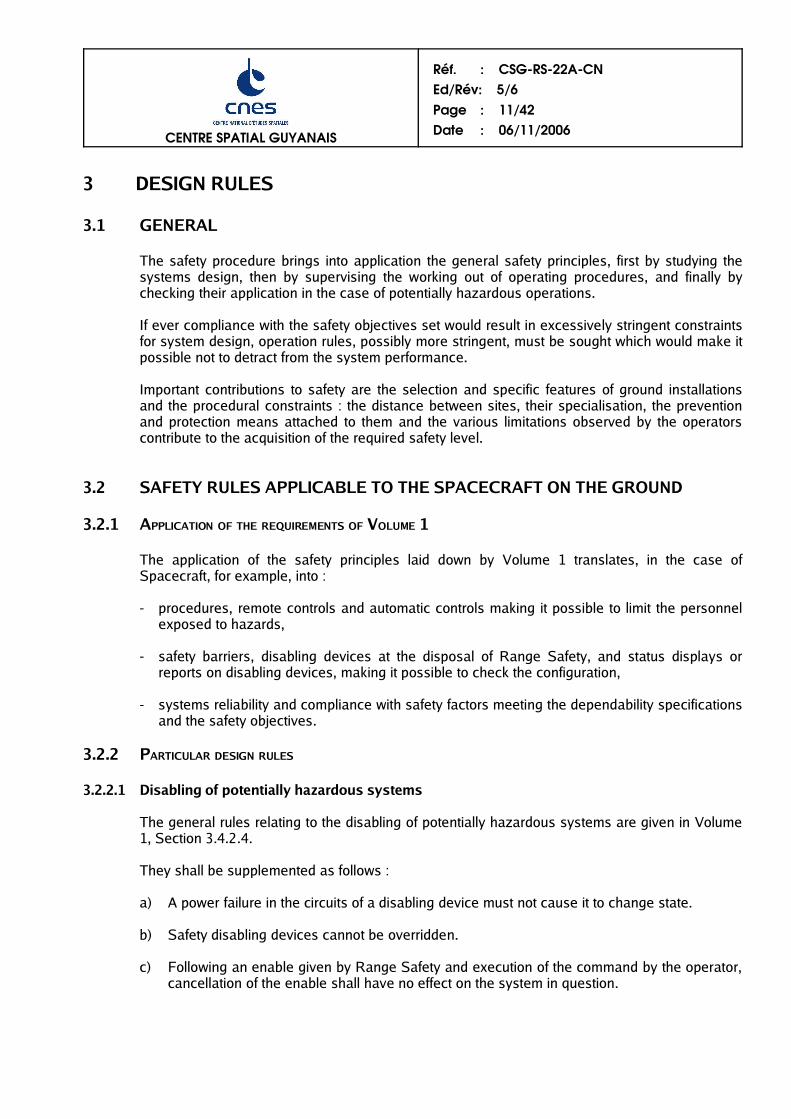
3.2.2.1 Disabling of potentially hazardous systems
The general rules relating to the disabling of potentially hazardous systems are given in Volume1, Section 3.4.2.4.
They shall be supplemented as follows :
a) A power failure in the circuits of a disabling device must not cause it to change state.
b) Safety disabling devices cannot be overridden.
c) Following an enable given by Range Safety and execution of the command by the operator,cancellation of the enable shall have no effect on the system in question.

CENTRE SPATIAL GUYANAIS
Réf. : CSGRS22ACNEd/Rév: 5/6Page : 12/42Date : 06/11/2006
3.2.2.2 Electrical systems
Electrical systems are considered as potentially hazardous systems, no matter what the voltage,current or frequency when one of the following conditions is satisfied:
- The electrical system contains one or more hazardous products.
- The electrical system may, in the event of failure(s), deliver power (electrical, thermal, etc.) oreffluents likely to cause direct damage (effect due to electrical origin) or indirect (effect on a potentiallyhazardous system connected to the electrical system).
An electrical system complying with French regulations on protection of workers in premises usingelectric current and for which a report certifying compliance with French regulations is delivered by anapproved inspection organization is not considered as a potentially hazardous system except if:
- it contains one or more hazardous products.
- it can, in case of failure(s), deliver power or effluents likely to cause indirect damage.
An electrical system non compliant with French regulations is considered potentially hazardous assoon as it can deliver a touch current (risk of electrical shock and burns) greater than or equal to:
- 3,5 mA for direct current and alternating current up to a 10 kHz frequency,
- 350*f mA (where f is the frequency given in MHz) for AC currents at a frequency varying from 10 kHzto 100 kHz.
- 35 mA for AC currents at a frequency greater than 100 kHz.
a) All electrical systems of Spacecraft ground support equipements shall include an emergencyswitching for electrical power supplies making it possible in a single operation to cut off allactive conductors under load. Emergency switching shall be easily accessible and easy toidentify.
b) Potentially hazardous electrical systems shall be protected against transient over-voltage andover-current.
c) Equipment shall be designed so that external metallic parts and shields can be grounded.
d) The following rules shall apply to cables:
- Cables shall offer resistance to and be protected from abrasion and twisting.
- Cables shall be selected according to toxicity, fire resistance, smoke emission criteria andcompatibility with adjacent liquids.
- Cable shield shall not be used as a grounding conductor or as a signal line (except forcoaxial cables in the latter case).
e) Conductors of potentially hazardous electrical circuits shall not run in the same cables or inthe same ducts as those used for other circuits.
f) Redundant leads shall run in different cables and ducts.

CENTRE SPATIAL GUYANAIS
Réf. : CSGRS22ACNEd/Rév: 5/6Page : 13/42Date : 06/11/2006
g) There shall be no sharp edges in structures in areas where cables are installed to avoid anypossibility of damaging cables.
h) The following rules apply to connectors:
- The connectors of potentially hazardous electrical circuits shall be designed in such a way thattheir connection is unambiguous (connector fool-proofing). Color code may be used but it shallnot replace fool-proofing.
- Potentially hazardous electrical connectors shall be appropriately guided when plugged in sothat female and male contacts do not undergo any constraint when being connected ordisconnected.
- Connectors shall have female contacts on power source supply and male contacts on serviceside.
- Damage to a connection (connector crushing or contact between two adjacent pins) shall notresult in any severe or catastrophic event.
- Connectors used in potentially hazardous electrical circuits shall be lockable.
- The position of pins shall prevent any risk of short-circuiting between two pins and between apin and the connector.
- The conductors of potentially hazardous electrical circuits shall have specific connectors andsockets which may in no case be common with those of other circuits.
i) The following rules shall apply to batteries:
- Batteries shall be easy to disconnect and remove.
- Connectors shall comply with the rules indicated above.
- If the battery is not connected, the connection terminals shall be protected to prevent any riskof short-circuiting.
- In case of a short circuit, electrolytic splatters shall be confined.
- Batteries shall be sufficiently vented to ensure that the concentration of discharged vapors isless than 25% of the Lower Explosive Limit (LIE).
j) The spacecraft and associated equipment shall be designed to:
- Limit the creation and build-up of electrostatic charges by the use of conductive materials.
- Not build up any electrostatic charge. Conductive parts (metallic or non-metallic), fixed ormobile, comprised in the spacecraft and associated equipment shall be interconnected andgrounded and can be connected to the grounding network of the ground installations.
Potentially hazardous electrical systems shall be designed so as to be insensitive to an electrostaticdischarge, a radiated electromagnetic emission (radar, lightning, radiocommunications, telephones)and an emission conducted by high current, low current networks and other conductive networks (forexample fluids) of the ground installations connected to the spacecraft and to its associated equipment.

CENTRE SPATIAL GUYANAIS
Réf. : CSGRS22ACNEd/Rév: 5/6Page : 14/42Date : 06/11/2006
Good works practices shall be observed, especially those concerning:
- the constitution of grounding layout plans,
- equipotential bonding, with regard to high frequency current, in electrical groundings, metallicconductive parts, shieldings and screens,
- wiring and routing of high and low current cables,
- separation of high current devices interfering with low current sensitive devices,
- electrical continuity and continuation of cable/connector, connector/socket andsocket/connected equipment shield.
The levels of insensitivity of such circuits to interference shall be specified and shall be checkedduring development.
3.2.2.3 Fluid systems
3.2.2.3.1 Definitions
a) A system containing one or more potentially hazardous fluids is classified as a "Potentiallyhazardous system" (see Appendix 2).
b) A system containing one or more pressurised fluids, which complies with French regulationsconcerning pressure vessels, shall not be considered a potentially hazardous system unlessat least one of the fluids is a potentially hazardous fluid.
c) A system containing one or more pressurised fluids which does not comply with Frenchregulations relating to pressure vessels, is classified as a "Potentially hazardous system"(see definition in Appendix 2) in any case where the dimensions and operating pressure ofthe system are as follows :
NATURE OF FLUID CONTAINER (CAPACITY) PIPING
GASES or liquids in which thevapour pressure at maximumallowable temperature exceedsnormal atmospheric pressure by0.5 bar.
P > 0.5 barAnd V > 1 litreAnd
PxV > 50 bar x lOr
P > 1,000 bar
P > 0.5 barAnd DN > 32And
PxDN > 1,000 bar
LIQUIDS in which the vapourpressure at maximum allowabletemperature is not more than 0.5bar above normal atmosphericpressure.
P > 10 bar And
PxV > 10,000 bar x lOr
P > 1,000 bar
P > 10 barAnd
DN > 200And
PxDN > 5,000 bar
V : internal volume of container.P : relative pressure.DN : nominal bore – Numerical designation of the nominal bore size common to allcomponents of a piping system, other than elements designated by their outside diameter orthread size. The DN value is rounded for reference purposes, and has no strict relation withmanufacturing dimensions. "DN" followed by a number indicates nominal bore size.
d) Elements are considered to be separate when a crack in one element cannot spread toanother element.

CENTRE SPATIAL GUYANAIS
Réf. : CSGRS22ACNEd/Rév: 5/6Page : 15/42Date : 06/11/2006
3.2.2.3.2 General rules
a) Pressurised fluid systems in compliance with French regulations relating to pressure vesselsare not subject to design requirements relating to safety other than those specified in theregulations.The customer shall be able to justify the conformity of its system by submitting a folderapproved by an inspection authority.
b) The circuits shall be designed so that mobile connectors shall be made mechanically fool-proof (couplings, lengths).
c) The lubricants used must be compatible with the fluids concerned.
d) Pressurised system couplings shall be of the "Safe-life" type (see definition in appendix 2).
e) "Potentially hazardous systems " must be subject to the "safety submission" process in anycase where a risk of injury to personnel exists.
3.2.2.3.3 Specific rules for pressurised fluid systems not complying with French regulations
Pressurised fluid systems not complying with French regulations relating to pressure vessels canbe designed in accordance with the specifications of European directive 97/23 or a standardrecognised by the Range Safety Department (for example A5-SG-1-X-10 and MIL-STD-1522A).
By default, the rules indicated below represent minimum applicable safety requirements.
a)The pressure vessels of on-board fluid systems shall have a burst safety factor at least equalto 2.
The vessels shall undergo a test programme in order to demonstrate their design andmanufacturing quality :
qualification tests on at least one vessel identical to the flight models, including :
• on the one hand :
* either cycling at at least 1.5 times the maximum ground working pressure requiredrepresenting, in number and duration, twice the cycles performed throughout theplanned life.
* either cycling at at least the maximum ground working pressure required, for a numberof cycles equal to 4 times those performed throughout the planned life,
• on the other hand, a burst pressure qualification test. This test involves increasing thepressure progressively up to at least calculated burst pressure. Actual burst pressureshall be greater than calculated burst pressure.
Proof pressure tests on each of the flight vessels, which shall include at least one test at at least 1.5 times the maximum ground working pressure required. The proof pressure,associated with loads applied during the proof pressure test, shall be withstood within theelastic limit of the material (i.e. yield strengh within 0.2% ) at proof pressure temperaturebeing reached, except in isolated zones.

CENTRE SPATIAL GUYANAIS
Réf. : CSGRS22ACNEd/Rév: 5/6Page : 16/42Date : 06/11/2006
b) The burst safety factor for on-board vessels can be lowered to 1.5 if additional factors ofevaluation such as fracture analysis, detection of leaks prior to failure, additional analyses ortests, etc. make it possible to ensure a safety level acceptable to Range Safety (for example,the "Leak Before Burst" (LBB) character with non-dangerous failure mode, demonstrated withinthe framework of standard MIL-STD-1522A, meets these requirements).
A fracture mechanics file shall be supplied in this case.
In these circumstances, the programmes described above in a) are modified as follows :
the qualification tests shall include :
• either cycling at at least the maximum ground working pressure required, for a number ofcycles equal to 4 times those performed throughout the planned life,
• a burst pressure qualification test, performed under the same conditions as above in a).
proof pressure tests are performed at a minimum pressure level of 1+ Jr times the maximumground working pressure required. 2
c) The following table summarizes qualification and proof pressure test conditions indicatedabove under a) and b), for on-board fluid system pressure vessels :
Safety factor 1.5 ≤ Jr < 2 Jr ≥ 2
Qualification
Test at at least 1.0 Pmss for 4Ncycles.
Test at burst pressure
- Test at at least 1.5 Pmss for 2Ncycles or test at at least 1.0 Pmssfor 4N cycles.
- Test at burst pressure
Proof pressureTest at at least 1 + Jr Pmss 2 Test at at least 1.5 Pmss
Jr : burst safety factor (see definition in Appendix 2).
Pmss : maximum ground working pressure required at service temperature.
N : number of cycles performed throughout the life of the vessel during the phasesof design, testing, transportation, storage, launching and, where applicable,life in orbit.
d) The ancillary equipment of on-board pressure circuits (pipes, couplings, valves and othercomponents) shall have a burst safety factor at least equal to 2.5.
3.2.2.3.4 Specific rules for potentially hazardous fluid systems
a) On-board systems designed to contain potentially hazardous fluids shall be designed so as totake into account the product specific properties (corrosion, toxicity, etc.).
b) Where a system incorporates a cryogenic fluid, the precautions required by the properties ofthis fluid shall be taken, in addition to compliance with material strength constraints, for theprotection of operators (incompatibility of products, corrosion, etc.).

CENTRE SPATIAL GUYANAIS
Réf. : CSGRS22ACNEd/Rév: 5/6Page : 17/42Date : 06/11/2006
3.2.2.4 Pyrotechnic systems
During phase 0 of the submission process, components of the pyrotechnic circuits as well as thepyrotechnic substances, if stripped during a nominal operation, or if the structure of the articlecontaining them does not protect them, shall be selected according to their low sensitivity toexternals stimuli, whether thermal (hot point, fire), mechanical (impact, shock, drop, friction,vibration), and electrical (static electricity, lightning, electromagnetic emission) and possiblychemical aggression.
During phase 0 of the submission process, it shall be proven that, for a given function, there isno article or pyrotechnic substance with a lesser reactivity when subject to an external stimulus.
A) Simplified classification
Apart from the officially regulated classifications for transportation and storage, the CNES/CSGuses a simplified classification based on the consequences of risks in the event of inadvertentactuation of electro-pyrotechnic devices :
- category A : systems which, through their own energy or by the sequences triggered by them,can injure or kill persons or damage property (catastrophic, severe or significantconsequences).
- category B : systems which, through their own energy or by the sequences triggered by them,do not result in injury to persons or damage to property.
The Project shall propose the classification to Range Safety and provide justifications for it. Thischoice will then be ratified by Range Safety.
The classification of a pyrotechnic device under category A or B may change depending on thelevel of integration into the Spacecraft.
Any pyrotechnic device for which the user has not provided for Range Safety a demonstrationallowing its classification shall be automatically classified under category A.
B "Medium energy" pyrotechnics
a) Electroexplosive initiators (igniters, initiating-detonators):
Electroexplosive initiators shall provide a level of safety at least equivalent to initiators of thetype 1 A, 1 W, 5 minutes "No Fire".
In addition to the specific design rules of the electrical systems of the Spacecraft and itsassociated equipment, these devices shall comply with the following rules:
sensitivity to radiated electromagnetic fields
The electrical circuits of pyrotechnic systems shall be designed so as to limit the current inducedon the ignition circuit to at least 20 dB below the maximum "No Fire" current, when they areexposed to an electromagnetic field:
– of a power density equal to 2 W/m² from 50 kHz to 50 Mhz,
– of a power density equal to 100 W/m² from 50 MHz to 18 GHz.
CENTRE SPATIAL GUYANAIS
Réf. : CSGRS22ACNEd/Rév: 5/6Page : 18/42Date : 06/11/2006
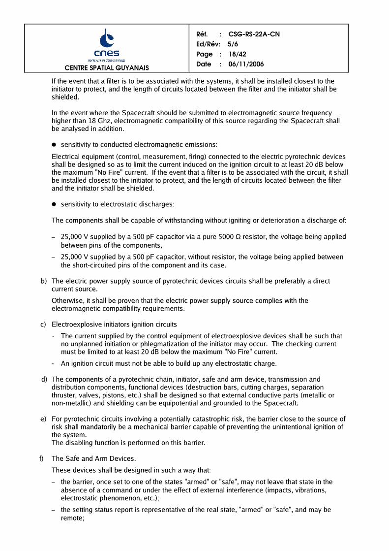
If the event that a filter is to be associated with the systems, it shall be installed closest to theinitiator to protect, and the length of circuits located between the filter and the initiator shall beshielded.
In the event where the Spacecraft should be submitted to electromagnetic source frequencyhigher than 18 Ghz, electromagnetic compatibility of this source regarding the Spacecraft shallbe analysed in addition.
sensitivity to conducted electromagnetic emissions:
Electrical equipment (control, measurement, firing) connected to the electric pyrotechnic devicesshall be designed so as to limit the current induced on the ignition circuit to at least 20 dB belowthe maximum "No Fire" current. If the event that a filter is to be associated with the circuit, it shallbe installed closest to the initiator to protect, and the length of circuits located between the filterand the initiator shall be shielded.
sensitivity to electrostatic discharges:
The components shall be capable of withstanding without igniting or deterioration a discharge of:
– 25,000 V supplied by a 500 pF capacitor via a pure 5000 Ω resistor, the voltage being appliedbetween pins of the components,
– 25,000 V supplied by a 500 pF capacitor, without resistor, the voltage being applied betweenthe short-circuited pins of the component and its case.
b) The electric power supply source of pyrotechnic devices circuits shall be preferably a directcurrent source.
Otherwise, it shall be proven that the electric power supply source complies with theelectromagnetic compatibility requirements.
c) Electroexplosive initiators ignition circuits
- The current supplied by the control equipment of electroexplosive devices shall be such thatno unplanned initiation or phlegmatization of the initiator may occur. The checking currentmust be limited to at least 20 dB below the maximum "No Fire" current.
- An ignition circuit must not be able to build up any electrostatic charge.
d) The components of a pyrotechnic chain, initiator, safe and arm device, transmission anddistribution components, functional devices (destruction bars, cutting charges, separationthruster, valves, pistons, etc.) shall be designed so that external conductive parts (metallic ornon-metallic) and shielding can be equipotential and grounded to the Spacecraft.
e) For pyrotechnic circuits involving a potentially catastrophic risk, the barrier close to the source ofrisk shall mandatorily be a mechanical barrier capable of preventing the unintentional ignition ofthe system.The disabling function is performed on this barrier.
f) The Safe and Arm Devices.
These devices shall be designed in such a way that:
– the barrier, once set to one of the states "armed" or "safe", may not leave that state in theabsence of a command or under the effect of external interference (impacts, vibrations,electrostatic phenomenon, etc.);
– the setting status report is representative of the real state, "armed" or "safe", and may beremote;

CENTRE SPATIAL GUYANAIS
Réf. : CSGRS22ACNEd/Rév: 5/6Page : 19/42Date : 06/11/2006
– the "armed" or "safe" state is displayed by an indicator physically linked to the disablingdevice;
– they may be remotely controlled, but manual disarming is always possible;
– assembly of the initiator is physically impossible if the device is not in "safe" position.
g) The location of the Safe and Arm devices shall provide easy access for assembly and connectionof initiators, and manual disarming.
C "High energy" pyrotechnics
High energy pyrotechnic devices shall be studied case by case in the relevant submissionprocedure.
D Solid propellant motor
The ignition command for this motor is disabled from the Console of the SafetyRepresentative (PRS). The ignition line shall include a Safe and Arm device for which thearming command is disabled by a specific relay activated from the PRS. A schematicdiagram for disabling of the arming command for a solid propellant motor is given on thefollowing page.

CENTRE SPATIAL GUYANAIS
Réf. : CSGRS22ACNEd/Rév: 5/6Page : 20/42Date : 06/11/2006
SCHEMATIC DIAGRAM FOR DISABLING OF THE ARMING COMMAND FOR A SOLID PROPELLANT MOTOR

CENTRE SPATIAL GUYANAIS
Réf. : CSGRS22ACNEd/Rév: 5/6Page : 21/42Date : 06/11/2006
3.2.2.5 Mechanical and electromechanical systems
For Spacecraft mechanical and electromechanical systems (systems for deployment, separation,etc.), a risk study must show that the risks induced by these systems are of an acceptableprobability level in compliance with safety objectives (cf. Volume 1, section 3.3).Particularly, the spacecraft lifting points ultimate safety factor must be > 2.
3.2.2.6 Environment-related aggression
- Explosive atmospheres
The payload devices shall be designed as to generate hazardous areas n°2, at most (see thedefinition in Volume 1 - appendix 2 : explosive atmosphere).
In such areas, electric onboard equipment shall perform the following minimumcharacteristics :
* equipment not generating electric arc or sparks during regular operating mode,* equipment not creating in regular operating mode, any hot surface of a temperature
equal or higher than the auto-igniting temperature of the used product vapours(hydrazin : 270°C - méthylhydrazin : 194°C - UH25 : 235°C - hydrogen : 560°C).
A safety submission shall be performed to define the operating conditions.
- Ionising radiation
The applicable rules are described in detail in the texts mentioned in the references(Appendix 1, B). They are supplemented by the following dispositions :
a) The submission for ionising radiation devices shall be presented to Range Safety assoon as possible. The CNES/CSG has six months to answer.
b) The effective dose for exposed workers is limited, depending on categories of workers.These limits are detailed in the documents in reference (appendix 1, B).
c) Radioactive elements must remain completely confined whatever the normal oraccidental situation liable to be encountered : destruction of the Launcher, crash on theground in the event of interruption of flight, atmospheric re-entry, etc.
3.2.2.7 Other Ground support equipments
Other ground support equipments of a Customer for which it is impossible to comply with theseRange Safety requirements must comply with safety regulations in force in the Country of theCustomer.

CENTRE SPATIAL GUYANAIS
Réf. : CSGRS22ACNEd/Rév: 5/6Page : 22/42Date : 06/11/2006
3.3 SAFETY RULES APPLICABLE TO THE SPACECRAFT IN FLIGHT
3.3.1 SPACECRAFT CONTAINING LIQUID PROPELLANT ONLY
Only the toxicity due to on-board propellants in the event of a ground crash or in-flight explosionis to be taken into account.
When each propellant tank contains a mass of less than 500kg, protection against toxicity can beobtained by adjusting the launching azimuth.
Otherwise, a specific analysis shall be made as part of the submission process.
3.3.2 SPACECRAFT CONTAINING A SOLID PROPELLANT
The following rules shall be applied :
a) A source of abnormal energy coming from the Launcher, such as an explosion, fire orimpact, must not result in motor ignition.
b) Any impact against the motor must not result in detonation of the propellant grain.
3.3.3 SPACECRAFT CONTAINING RADIOACTIVE MATERIALS
Rule c). of section 3.2.2.6 shall be applied.
3.3.4 ELECTROMAGNETIC COMPATIBILITY
Electromagnetic compatibility between the various elements (Launcher/Spacecraft unit, groundinstallations) and protection of electro-pyrotechnic devices shall be ensured.
For this purpose, Range Safety can, in particular, impose restrictions on the level ofelectromagnetic radiation in Spacecraft.
CENTRE SPATIAL GUYANAIS
Réf. : CSGRS22ACNEd/Rév: 5/6Page : 23/42Date : 06/11/2006
4 OPERATIONAL RULES
4.1 APPLICATION OF THE REQUIREMENTS OF VOLUME 1
The operational principles set out in Volume 1 are applicable to Spacecraft.
4.2 SAFETY RULES APPLICABLE TO THE SPACECRAFT ON THE GROUND
4.2.1 GENERAL RULES
a) For all potentially hazardous operations, it shall be possible, from certain key points, torestore the system to safe condition (depressurisation, drainage of propellants or toxicproducts, circuit disarming, etc.).
The operators shall have corresponding emergency procedures and safing procedures,before the start of any potentially hazardous operation.
The safety instructions specific to an operation shall appear in the corresponding procedure.
b) Any operating trouble, even transient, shall be recorded in a non-conformance report whichshall lead to an investigation. The configuration in which the trouble appeared shall berecorded to allow effective analysis.
Any incident, during the whole of the Spacecraft's life, concerning a potentially hazardouscircuit or part, shall undergo an analysis of which Range Safety shall be kept informed.
c) Range Safety shall be organised to perform monitoring of the potentially hazardousconfigurations for which it is responsible.
d) Range Safety shall be informed in real time of the Spacecraft configuration for all aspectsrelating to security, safety and environment.
In particular, any modification to a potentially hazardous system shall be authorised by theSafety representative.
4.2.2 PARTICULAR RULES
Only the essential rules recommended by Range Safety are described below. Other rulesrelating to labour safety are brought together in the collection of CNES/CSG ''industrial safetyinstructions", document mentioned in the references (Appendix 1, K).
4.2.2.1 Electrical systems
(See also "Explosive atmospheres" in § 4.2.2.5 hereafter).The usual accident prevention rules applied during operations on electrical systems shall becomplied with. They are described in detail in the texts mentioned in the references (Appendix 1,C).
Before a system can be placed in a hazard configuration, its circuits shall be tested to check itsconfiguration and satisfactory working order.
CENTRE SPATIAL GUYANAIS
Réf. : CSGRS22ACNEd/Rév: 5/6Page : 24/42Date : 06/11/2006
Special attention shall be paid to the following points :
a) The various components of the Spacecraft, the associated equipment and ground systemsmust not build up any electrostatic charge during spacecraft or stage integration operations aswell as during transfer operations.
In all these operations, the fixed or mobile conducting elements (metallic or non-metallic)comprised in these systems must be interconnected by means of equipotential bonding and
grounded.
Bonding must be checked electrically.
The recommended maximum value for electrical bonding and grounding resistance is 10 Ωfor metallic parts and 106 Ω for non-metallic conductive parts.
b) Before any transfer of the Spacecraft, make sure that potentially hazardous electrical circuitsare in safe configuration and that they cannot change configuration during transfer.
c) It is requested of the users that check the umbilical cords allocated to them, by an active testbefore connection to the Spacecraft, using a satellite simulator, at least for those controlsinvolving a risk.
d) The Safe and Arm device must be in safe position in attendance of personnel ; this safeposition must be checked.
4.2.2.2 Fluid systems
4.2.2.2.1 General rules
a) Fluid systems shall undergo pressure tests before their arrival at CSG.
b) After the system has been tested, the maximum expected operating pressure required mustnever be exceeded.
c) In the event of repair or maintenance, a representative seal-tightness test is required prior toreturn to service. Furthermore, if the operation is not limited to disassembly/reassembly butincludes more extensive work (welding, forming, etc.), the pressure system shall be inspectedand tested after this work by an improved inspection authority.
d) Any non-compliance with pressure system operating specifications shall be submitted forapproval by the Range Safety Department.
e) The pressurisation and depressurisation rates shall not create any uncontrollable potentiallyhazardous situations (temperature gradient, surge, etc.).
f) Relative pressure (expressed in mbar) applied to equipment on which manual intervention(disassembly, repair, tightening or slackening of couplings, etc.) occurs, shall be such that theproduct of said pressure by the surface area of the section of the orifice opened (expressed incm²) is less than 1,000.The safety of operators shall be ensured by the number of barriers left in place and, wherenecessary, by individual protection appropriate for potentially hazardous fluids.
g) A pressurised fluid system not complying with the requirements of French regulationsconcerning pressure vessels intrinsically creates an hazardous area (see definition in

CENTRE SPATIAL GUYANAIS
Réf. : CSGRS22ACNEd/Rév: 5/6Page : 25/42Date : 06/11/2006
Appendix 2). Access to the hazardous area shall be subject to specific conditions orprohibited.
h) A LBB type pressure vessel, used in the requisite pressure domain to obtain LBBclassification, only creates an hazardous area insofar as there is the risk of possible leakageof the fluid contained.
4.2.2.2.2 Specific rules for pressurised fluid systems not complying with French regulationsconcerning pressure vessels.
a) Special case of a welded system
The system shall have undergone testing at 1.5 times the maximum pressure in the presence ofpersonnel prior to its arrival at the CSG, where the burst safety factor is ≥ 2. Otherwise listing isrequired at 1 + Jr times the above pressure.
2(Jr: burst safety factor defined in Appendix 2).
b) Operational constraints relating to vessels
Nominal pressure resistance characteristics shall be validated by demonstration that thevessel used operationally has not been subjected to any attack (mechanical, thermal,electrical, etc.) which may have impaired its characteristics.
During the dynamic pressurisation and depressurisation phases and under static conditions,operational constraints are set by reference to safety factor J, defined as the ratio ofadmissible burst pressure to the relative pressure reached by the system in question at theinstant concerned :
J= Admissible burst pressure Instantaneous relative pressure taken into account
Variable factor J is also such that J ≥ Jr.
The presence of personnel in the hazardous area (to be specified case by case) is governed bythe following rule :
Safety factor J Access in static phase Access in dynamic phase (6)
J ≥ 43 ≤ J < 4
Jmin ≤ J < 3 (5)
No constraintNo constraint
Controlled access (4)
No constraintControlled access (4)
Limited access (7)
(4) Only personnel directly concerned with the operations for which their presence in thehazardous area is essential are admitted. These operations can concern any part of thepayload other than the vessel in question.
(5) In the general case, the lower limit value Jmin for J is Jr = 2.Under the conditions indicated in § 3.2.2.3.3 b), this value can be reduced to Jr = 1.5.
(6) The dynamic phase includes the movement of fluid(s) and handling of pressure vessel(s),but excludes the dwell times to be complied with for balancing temperatures afterpressurisation.
(7) Only those personnel concerned with the pressurisation/depressurisation operation areadmitted, in the case where the operation cannot be conducted from a remote position.
CENTRE SPATIAL GUYANAIS
Réf. : CSGRS22ACNEd/Rév: 5/6Page : 26/42Date : 06/11/2006
4.2.2.2.3 Specific rules for potentially hazardous fluid systems
a) Systems receiving potentially hazardous fluids shall systematically undergo a leak test atCSG before filling. This test should be conducted at or above the maximum operatingpressure expected for the presence of personnel.
b) Compliance with restricted access for operators in an hazardous area, and the utilisation ofremote control, are defined according to the aggressivity of the potentially hazardous fluids,and the risks that they generate. However, for any operation on a system containingpotentially hazardous fluids, a team of at least two operators, or more if justified, is required(see Volume 1, § 4.2.2.5).
c) In the case of an operation involving a toxic fluid, toxicity measurements shall be takenbefore, during and after the operation.
d) Where personnel are required to intervene during the transfer of potentially hazardous fluids,all personnel involved must wear appropriate safety equipment.
e) Before any work or interventions requiring the opening up of parts that have contained toxicfluids, the system shall be drained and personnel involved shall be protected if the elementshave not been decontaminated.
f) For any intentional discharge of liquid or gaseous effluents involving a hazard for persons,property or the environment, the approval of Range Safety shall be obtained and the workshall be performed in accordance with an approved procedure.
g) All conductive parts whether metallic or non-metallic, fixed or mobile, of tanks, transfercircuits or associated devices (valves, filters, etc.) must be interconnected by equipotentialbonding and grounded before and during filling or draining it with propellant.
4.2.2.3 (Blank)
4.2.2.4 Pyrotechnic systems
The French regulations applicable to pyrotechnic systems, mentioned in appendix, give in detailthe rules to be complied with for the operation of pyrotechnic systems. Only the particular rulesspecific to the CSG are mentioned below.
a) Prior notification shall be given of the arrival of pyrotechnic equipment on the CSG. Thesafety data sheet for new equipment shall specify the proposed pyrotechnic classificationand the test results (impact, temperature, etc.).
b) Electrical test equipment shall be of a model accepted by Range Safety.
c) Electropyrotechnic components shall be in a safe configuration during storage and handlingoperations and after assembly. Allowance shall be made for the possibility of externalaggression.
Before connecting these components, a check shall be made to ensure the system is de-energised (stray voltage test).
Any periods of radio silence and switching inhibition which may be required shall beindicated on the procedures.
CENTRE SPATIAL GUYANAIS
Réf. : CSGRS22ACNEd/Rév: 5/6Page : 27/42Date : 06/11/2006
d) The connection of potentially hazardous electro-pyrotechnic circuits shall be performed aslate as possible in the sequence of Spacecraft preparation.
As soon as these circuits have been connected, the Safety representative shall be able tohave access, at any time, to check the condition of the pyrotechnic circuit.
e) The operating procedure shall provide for the raising of barriers close to potentiallyhazardous parts before the raising of barriers located in the vicinity of the energy source.
f) Arming of the Spacecraft shall be performed in the launch zone, after evacuating thepersonnel.
g) Pyrotechnic components which are unused or have reached their time limit shall berecovered by their owner or destroyed under the control of Range Safety.
4.2.2.5 Rules concerning environment-related aggression
- Explosive atmospheres
It is forbidden to operate unprotected electric equipment in an explosion hazardous area.
Electric equipment must not be operated in an explosion hazardous area, when not inconformance with the rules set out in § 3.2.2.6 hereabove.
The mobile electric equipment (portable equipment, electric automotive trucks) which are notin conformance with these rules shall be subjected to a safety submission to define itsoperating conditions.
- Confined atmospheres
The following rules shall be applied :
a) Before personnel enters a confined atmosphere, the oxygen level shall be checked.
b) Personnel required to enter a confined atmosphere shall become acquainted with andapply the particular safety instructions stipulating the required conduct to avoid the risk ofasphyxiation.
c) Any work in a confined atmosphere with under-oxygenated air risk requires the presenceof a at least two independant detectors, one of them being stationary, each of themprovided with a low level alarm monitoring the atmosphere continuously. The low levelalarm to take into account for detection is of 19% oxygen (percentage by volume).
d) All personnel shall have at their disposal a breathing mask or airtight clothing suppliedwith breathable air.
e) Toxicity measurements shall be performed if necessary.

CENTRE SPATIAL GUYANAIS
Réf. : CSGRS22ACNEd/Rév: 5/6Page : 28/42Date : 06/11/2006
- Toxic atmospheres
a) Devices for detecting toxic substances shall be set so that the alarms are triggered whenthe concentration of toxic substance in the atmosphere of the workplace is equal to 90%of the Limit Exposure Value (VLE).
b) Personnel required to enter an atmosphere which is liable to be toxic shall becomeacquainted with and apply the instructions laid down to prevent the risk of inhalation oftoxic substances.
c) Any work in an area where there exists a risk of toxic atmosphere requires the presenceof a detector monitoring the atmosphere continuously. The detector shall be providedwith an alarm.
d) All personnel shall have at their disposal a breathing mask or airtight clothing suppliedwith breathable air.
- Ionising radiation
The applicable rules are described in detail in the texts mentioned in the references(Appendix 1, B). These rules are supplemented by the following provisions :
a) Range Safety shall be informed of any source of ionising radiation before it is introducedonto the CSG.
b) Devices containing radioactive substances, or devices generating ionizing radiation aresubmitted to authorization for possession by DGSNR (French general directorate fornuclear safety and protection from ionizing radiation).
c) Radioactive sources shall be stored in rooms approved by Range Safety. Access tothese rooms shall be prohibited:
- to unqualified personnel;
- outside authorised periods of use.
d) When using radioactive sources or ionising generators on areas where the CNES/CSG isin charge of the safety function, the following measures shall be taken :
- Installation of the access control facilities required by Range Safety. The number ofpersons taking part in the operations shall be as small as possible, although not lessthan two.
- Wearing of the supplied dosimetric badges (monthly dosimeter and operationaldosimeter) and where applicable individual means of protection required by RangeSafety.
- Use of sources of ionising radiation in accordance with procedures approved by theCNES/CSG.
e) Operations involving the use of sources of ionising radiation may be carried out only byqualified personnel which has passed a medical inspection entitling it to perform suchwork. This medical inspection may be passed in French Guiana, but the personnelconcerned may produce a fitness certificate from their country of origin, provided that itsperiod of validity covers the date of the operations.

CENTRE SPATIAL GUYANAIS
Réf. : CSGRS22ACNEd/Rév: 5/6Page : 29/42Date : 06/11/2006
- Non-ionising radiation
For frequencies from 10kHz to 300 GHz, zones must be defined according to the category ofpersons, characteristics of the electromagnetic broadcast and the duration of thebroadcasting. These zones are computed in conformance to the standard C 18-610 (ENV50166-2) referenced in appendix 1, B-7.
- Laser radiation
The laser radiation devices used in industry are not covered by French regulations. However,they must be classified in accordance with the categories of French Standard NF EN 60 825-1, cf. appendix 1, B).
Their use on the sites where the CNES/CSG is in charge of the safety function, shall besubject to the following rules :
a) The use of lasers shall be subject to the approval of Range Safety, which will confirm thedevice's class.
b) They shall be used in a room or a place reserved for that application, enclosed or bounded,and with entrances posted with a danger warning panel (French Standard NF X 08-003, cf.appendix 1, B). A special signal shall warn of the existence of emission.
c) The entrances and openings to these rooms shall not be in the axis of direct or derivedradiation. The ground shall be free of obstacles.
d) The causes of accidental reflection and diffusion of laser beams shall be eliminated(polished surfaces, non-matt paints or coatings).
e) The path of foreseeable potentially hazardous radiation (normal or abnormal) shall ifpossible be completely caged in by suitable screens.
When the beam is not completely enclosed, its path shall be determined, together with itsnormal or accidental deviations, reflections or diffusion.
f) During emission, it must not be possible to change the orientation of a laser emitter and ofthe optical elements placed in the beam.
g) Potentially hazardous laser radiation shall be absorbed at its termination. The points ofbeam arrival shall be protected from reflections (energy absorbers or traps) and shall notcontain easily flammable materials.
h) The control of class 3 and 4 lasers will require the use of a control key, which will beremoved when the device is not in use, and will be kept by an authorised person.
i) Class 3 and 4 lasers shall have an emergency stoppage control.
j) Access to areas in which laser radiation is potentially hazardous shall be restricted toauthorised persons.

CENTRE SPATIAL GUYANAIS
Réf. : CSGRS22ACNEd/Rév: 5/6Page : 30/42Date : 06/11/2006
k) The persons present shall not carry any reflecting objects.
l) The alignment and adjustment operations required prior to powerful laser emissions shall becarried out, insofar as possible, with reduced power.
- Lightning and electrical storms
Systems where lightning may be a potential hazard with catastrophic or severe consequencesmust be protected against the effects of direct or indirect lightning strokes in compliance with theregulations in force and good works practice (see documents mentioned in appendix 1, E).
An active lightning protection system (detection and lightning warning) providing a lightningforecast compatible with the time required to restore the involved system to a safe configuration,as defined in the procedure, must be implemented for operations involving a potential hazardwith catastrophic or severe consequences:
- outside any installation
- inside any installation during docking (or undocking) operations involving articles, if the grounding of these articles to be docked (or to be undocked) is not possible (for exemple :hooking (or unhooking) of an article to hoisting equipment).
- Handling operations and hoisting equipment
The main hoisting and handling equipment consists of trolleys and accessories used for loadsupport (slings, lifting beams, hooks, fastening rings, lifting points integral with the Spacecraftstructures, etc.).
a) Handling and hoisting equipment shall be operated only by authorised and qualifiedpersonnel which has received appropriate training on the CSG.
b) This equipment and its accessories shall be checked annually by an approvedorganisation and the results shall be made available to Range Safety.
In the event that such checks are not feasible (e.g., for Spacecraft structural elements),the quantity and characteristics of handling of this element (impacts, thresholdsexceeded, etc.) shall be made available to Range Safety.
4.2.2.6 Other ground support equipments
Other ground support equipments of a Customer that cannot meet requirements of these RangeSafety regulations must be used and operated only by the Customer, must comply with safetyregulations of the Customer country and with manufacturer recommandations.

CENTRE SPATIAL GUYANAIS
Réf. : CSGRS22ACNEd/Rév: 5/6Page : 31/42Date : 06/11/2006
4.3 SAFETY RULES APPLICABLE TO THE SPACECRAFT IN FLIGHT
In-flight arming (removal of the last safety barrier) and the final ignition command shall beauthorised only after separation of the Spacecraft from the structure of the Launcher carrying it.
4.4 PRINCIPLES FOR DRAWING UP THE PROCEDURES FOR POTENTIALLYHAZARDOUS OPERATIONS
The Customer's representative and the Safety representative shall have copies of the procedurefor the operation in question, which shall have been approved beforehand. This procedure shallbe established by the Customer and submitted for approval to Range Safety in phase 3 of thesubmission process.
A procedure relating to a potentially hazardous operation shall contain the following information,drawn up in clear, precise language easily understandable by all involved :
- identification of the procedure, including its edition number,
- identification of the operation and its title (reference user procedure),
- estimated duration of the operation,
- quantity and qualifications of operators,
- step-by-step description of the operation, with a clear indication of potentially hazardousphases,
- description of specific hazards to which the operators are exposed,
- description of tooling, products used and individual means of protection,
- identification of the services set up for operational support,
- special measures and reference to procedures for restoring the system to safe condition inthe event of degraded operation.

CENTRE SPATIAL GUYANAIS
Réf. : CSGRS22ACNEd/Rév: 5/6Page : 32/42Date : 06/11/2006
4.5 SPECIFIC RULES APPLICABLE ON THE EPCU
The sites, their equipment, and the protection and intervention facilities are described in theEPCU Manual.
The general rules relating to the qualification, training and physical fitness of the operators are tobe found in Section 3.9 of Volume 1.
With respect to Spacecraft projects, the documents which must be supplied by the SpacecraftCustomer to Range Safety are as follows :
- medical certificate of physical fitness of fuelmen and personnel responsible for radiographicexamination of solid-propellant motors,
- certificate of qualification of personnel responsible for the handling, installation and inspectionof pyrotechnic substances,
- certificate of fitness for handling radioactive substances.
CENTRE SPATIAL GUYANAIS
Réf. : CSGRS22ACNEd/Rév: 5/6Page : 33/42Date : 06/11/2006
5 SUBMISSION PRINCIPLES
5.1 GENERAL
The principle of Safety submissions is described in Volume 1, Section 3.7.
In the case of payloads, if the submitted system is a derivative of a system already submitted toCNES/CSG Range Safety, the submission can be performed by difference with the systemalready submitted. In this case, the number of systems submitted by difference refering tosynthetic file of the reference submission is limited to two, within a no more than three yearsperiod.
For a Spacecraft already developed, qualified on the ground and launched from other launchbases, the formal submission procedure may be shortened.
The present chapter gives, for each phase :
- the scope of the phase,
- the non-exhaustive list of the main documents which will be requested by Range Safety fromthe Spacecraft Customer (via Arianespace, unless otherwise stated),
- the contents of the submission file established by Range Safety (classification/approvalsheets).
The list, as exhaustive as possible, of all information, documents and certificates which will berequested of the Customer during the various phases of safety submission for the project (safetycheck-list) is given in Volume 3.
The forms making up the Spacecraft submission file and the list of submission sheet codes arealso given in Volume 3.
All documents or qualification reports shall be supplied as soon as possible, even if thesubmission phase for which the document is to be supplied is not yet open.
Throughout the submission process, additional documents may be requested by Range Safety toobtain a better understanding of safety questions (safety, labour safety and environment).
The documents submitted to Range Safety shall be written in French or English (see Volume 1).

CENTRE SPATIAL GUYANAIS
Réf. : CSGRS22ACNEd/Rév: 5/6Page : 34/42Date : 06/11/2006
5.2 PHASES OF SUBMISSION
Phases 1, 2 and 3 can be carried out simultaneously, since the opening of one phase does notrequire that the preceding phase be closed.
A submission phase is declared closed when all the documents to be established by RangeSafety have been issued and all comments have been taken into account.
5.2.1 PHASE 0 - FEASIBILITY
5.2.1.1 Scope
This phase is systematically performed for each new platform.
It shall be closed before signature of the contracts between the Customer and Arianespace,since it is a necessary condition for Spacecraft operation at the CSG.
5.2.1.2 Documents to be supplied to Range Safety
The Spacecraft Customer shall supply a file containing :
- a description of the potentially hazardous system(s),
- an overview of the technical options considered,
- a list of risks associated with the on-board system and specific ground support equipment,
- where applicable, the list of standards and regulations proposed for application to the project.
5.2.1.3 Documents to be drawn up by Range Safety
After analysing the solutions considered, Range Safety will give its opinion via the submission filewhich will contain either an approval of the file submitted by the Customer, or the amendments tobe made to the project to make it acceptable.

CENTRE SPATIAL GUYANAIS
Réf. : CSGRS22ACNEd/Rév: 5/6Page : 35/42Date : 06/11/2006
5.2.2 PHASE 1 - DESIGN
5.2.2.1 Scope
This phase shall be opened in all cases.
During this phase, Range Safety will :
- check that the design of potentially hazardous systems of the Spacecraft and ground supportequipment comply with the Safety regulations,
- express, where applicable, particular requirements, notably for the disabling of potentiallyhazardous circuits involving hazards which may have catastrophic or severe consequencesand/or for their display.
This phase shall be opened as soon as possible after signature of the launch contract betweenthe Spacecraft Customer and Arianespace.
It begins with the submission to Range Safety of the Application for Launcher Use, which usuallytakes place 29 months prior to launching. Insofar as possible, this phase shall be closed for thePreliminary Design Review of the satellite.
5.2.2.2 Documents to be supplied to Range Safety
- Compulsory documents
The Customer shall supply a file containing, in particular :
. the detailed description of potentially hazardous systems, their monitoring and controlcircuits and their ground support equipment,
. the planned frequency pattern for transmitters and receivers with the transmissioncharacteristics (spectrum, power, modulation, encoding, etc.),
. the preliminary hazard analysis, even partial,
. the qualification plans for important components of potentially hazardous systems,
. all information relating to potentially hazardous systems (including, in particular, reliabilitydata) allowing estimation of the level of risk.
- Recommended documents
. The "Product Assurance" or "Dependability" document.

CENTRE SPATIAL GUYANAIS
Réf. : CSGRS22ACNEd/Rév: 5/6Page : 36/42Date : 06/11/2006
5.2.2.3 Documents to be drawn up by Range Safety
After examining the file presented, Range Safety shall draw up the submission file which :
- lists the system's potentially hazardous circuits with their classification,
- gives its approval of the principles adopted for potentially hazardous circuits or, otherwise,expresses its requirements,
- presents a list of components for which a more thorough examination is required : detailedcharacteristics, special tests, additional studies.
Via the submission sheets, Range Safety gives its opinion concerning the documentationsupplied in phase 1 and recalls its requirements for phase 2.
5.2.3 PHASE 2 - MANUFACTURING
5.2.3.1 Scope
During this phase, Range Safety checks that the manufacturing and qualification of theSpacecraft and ground support equipment comply with the requirements expressed duringsubmission phase 1.
Also during this phase, the specific characteristics of interfaces between the Spacecraft, theground support equipment and the various facilities of the CSG are given.
This phase shall start with the supply to Range Safety of the Interface Control document or assoon as the documents to be supplied in phase 2 have reached Range Safety. Insofar aspossible, it shall be closed before the Critical Design Review of the satellite.
5.2.3.2 Documents to be supplied to Range Safety
The Customer shall supply a file containing, in particular :
- the results of partial or complete qualification tests on potentially hazardous systems,
- the plan of partial or complete acceptance tests on the potentially hazardous systems,
- any particular study or design calculation sheet allowing assessment of system characteristics(fracture analysis, etc.),
- the Interface Control Document (DCI) to be supplied by Arianespace,

CENTRE SPATIAL GUYANAIS
Réf. : CSGRS22ACNEd/Rév: 5/6Page : 37/42Date : 06/11/2006
- the preliminary hazard analysis enriched by data from the current phase,
- where applicable, amendments to the plan of transmission frequencies and characteristics.
The following documents may be received during this phase :
- the Satellite Operations Plan in a preliminary version,
- the list of CSG operation procedures, in particular the list of procedures relating to potentiallyhazardous operations.
5.2.3.3 Documents to be drawn up by Range Safety
Via the submission sheets, Range Safety gives its opinion concerning the documentationsupplied in phase 2 and recalls its requirements for phase 3.
5.2.4 PHASE 3 - OPERATION
5.2.4.1 Scope
During this phase, Range Safety checks that operation on the CSG meets the requirements ofthe Safety Regulations.
This phase shall start at the latest 6 months prior to launching, so as to allow Range Safety tomake comments prior to the Spacecraft Pre-Shipment Review.
5.2.4.2 Documents to be supplied to Range Safety
- The CSG operation procedures requested by Range Safety, including safing procedures andthe emergency procedures in the event of an incident ; these procedures shall comply withthe following rules :
. identify elementary potentially hazardous operations by a special sign,
. take into account the specific features of the CSG (sites, means, designations, etc.),
. specify, for each elementary step, the quantity and functions of persons whose presence inhazardous areas is essential,
. define the list of resources and products used,
. specify, step by step, the procedure for restoring safe conditions,
. indicate the duration of operations, including those for restoring safe conditions, and anypauses.

CENTRE SPATIAL GUYANAIS
Réf. : CSGRS22ACNEd/Rév: 5/6Page : 38/42Date : 06/11/2006
- The results of acceptance tests on certain components of potentially hazardous systems, inparticular the test certificates for pressurised vessels ; these documents may be suppliedupon equipment arrival at CSG.
- The authorisations to keep and use certain potentially hazardous products (such asradioactive materials).
- a booked engagement of the Customer certifying :
• that his ground support equipments comply with safety regulations in force in his owncountry,
• that he use his ground support equipments according to the safety regulations in force inhis own country and the manufacter recommmandations,
• that he operates his ground support equipments only whith his own employees or his sub-contractor ones,
• that he takes charge of Range Safety tasks which are connected with his ground supportequipments.
- The certificates of medical fitness for operators working on certain potentially hazardoussystems, e.g., which emit ionising radiation or contain toxic substances. These documentsmay be supplied upon arrival at CSG.
- The certificates authorising operators for the handling of pyrotechnic items.
- The Spacecraft Operations Plan in its final version, containing, in particular, the final list ofprocedures, the operation sheets, and the schedule of operations.
- The Combined Operations Plan with the Launcher,
to be supplied by Arianespace,
- the Interleaved Operations Plan,
to be supplied by the Operations Division of the CNES/CSG.
Note : At the specific request of Range Safety, a safety analysis of the most critical phases ofpotentially hazardous operations may be requested from the project.
5.2.4.3 Documents to be drawn up by Range Safety
The Safety submission file shall contain, in particular, the following documents :
- the sheets of approval or comments on Operation Plans,
- the sheets of approval or comments on procedures relating to potentially hazardousoperations,
- the approval sheets of equipment and products used.

CENTRE SPATIAL GUYANAIS
Réf. : CSGRS22ACNEd/Rév: 5/6Page : 39/42Date : 06/11/2006
5.3 MANAGEMENT OF SUBMISSION FILES
For each project, Range Safety opens a "Safety File" containing :
- a description of the Spacecraft,
- the documents issued by Arianespace (DCI, etc.),
- the documents relating to operations (Spacecraft Operations Plan, operation sheets, etc.),
- the documents relating to phases 0, 1, 2 and 3 transmitted by the Customer (qualification andacceptance certificates, etc.),
- the procedures for potentially hazardous operations,
- campaign documents.
This file is archived by Range Safety.
5.4 REVIEWS / MEETINGS
Range Safety takes part in the ordinary meetings provided for between Arianespace and theCustomer to deal with specific safety problems.

CENTRE SPATIAL GUYANAIS
Réf. : CSGRS22ACNEd/Rév: 5/6Page : 40/42Date : 06/11/2006
Page intentionally left blank

CENTRE SPATIAL GUYANAIS
Réf. : CSGRS22ACNEd/Rév: 5/6Page : 41/42Date : 06/11/2006
APPENDIX 1
REFERENCE DOCUMENTS
APPENDIX 2
TERMINOLOGY
APPENDIX 3
ABREVIATIONS
See the corresponding appendices in Volume 1.

CENTRE SPATIAL GUYANAIS
Réf. : CSGRS22ACNEd/Rév: 5/6Page : 42/42Date : 06/11/2006
Page intentionally left blank