specification for roads and drains
TRANSCRIPT

SPECIFICATION
FOR
ROADS AND DRAINS
SECTION D STORMWATER DRAINS, STRUCTURES
AND PROPERTY INLETS

Specification for Road and Drainage Works Last updated 2 Mar 2006
Page 1 Section D Stormwater Drains, Structures and Property Inlets
INDEX TO CLAUSES STORMWATER DRAINS D.1 Description 3
D.2 Pipes 3
D.3 Supply and Delivery of Pipes and Box Culverts 3
D.4 Handling of Pipes and Box Culverts 4
D.5 Statutory Regulations 4
D.6 Excavation 4
D.7 Existing Paved Surfaces 6
D.8 Construction of Fills Prior to Installation of Pipe 6
D.9 Removal and Disposal of Salvaged Material 6
D.10 Bedding Material 6
D.11 Laying and Jointing 6
D.12 Backfilling 7
D.13 Trenches Under Existing or Proposed Road Pavements 8
D.14 Trenches Under Existing or Proposed Footpaths and Driveways 8
D.15 Compaction of Backfill 8
D.16 CCTV Verification 9
D.17 Disposal of Surplus Soil 10
D.18 De-Watering 10
D.19 Timbering of Trenches 10
D.20 Removal and/or Relaying of Existing Pipes 10
D.21 Exit and Entry Channels 11
DRAINAGE STRUCTURES D.22 General 12
D.23 Concrete 12
D.24 Formwork 12
D.25 Inlet and Outlet Drains 13
D.26 Pits within the Road Reserve 13
D.27 Step Irons 13
D.28 Future Inlet Provision 13
D.29 Pits in Footpaths or Driveways 14

Specification for Road and Drainage Works Last updated 2 Mar 2006
Page 2 Section D Stormwater Drains, Structures and Property Inlets
D.30 Height of Lift 14
D.31 Steel Covers and Gratings 14
D.32 Lintel Slabs 14
D.33 Side Entry Pit Lintels 14
D.34 Anchor Blocks 15
D.35 End Walls 15
D.36 Soakage Areas and Pits 15
PROPERTY INLETS D.37 General 16
D.38 Details of Inlets 16
D.35 Existing Property Drains 16
APPENDICIES D1 CCTV Inspection Acceptance Criteria 17

Specification for Road and Drainage Works Last updated 2 Mar 2006
Page 3 Section D Stormwater Drains, Structures and Property Inlets
SECTION D: STORMWATER DRAINS, PITS AND PROPERTY INLETS
STORMWATER DRAINS D.1 DESCRIPTION
This work includes the supply, delivery and laying of all precast underground stormwater drains and culverts, together with the construction of drainage pits, manholes and endwalls.
The general terms, "underground stormwater drains" and "pipes", shall be taken to refer also to culverts for the purpose of this specification.
D.2 PIPES
Pipe sections for work under this specification shall comply with the following standards:-
• AS/NZS 1254:2002 PVC pipes and fittings for storm or surface
water applications • AS/NZS 1260:2002 PVC-U pipes and fittings for drain, waste and
vent application • AS 1597 Precast reinforced concrete box culverts • AS 1646 Elastomeric seals for waterworks purposes • AS 2032-1977 Code of practice for installation of UPVC pipe
systems • AS/NZS 4129:2000 Fittings for polyethylene (PE) pipes for
pressure applications • AS/NZS 2566.1:1998 Buried flexible pipelines - structural design • AS/NZS 2566.2:2002 Buried flexible pipelines – Installation • AS 3725-1989 Loads on buried concrete pipes • AS 4058-1992 Precast concrete pipes (pressure and non-pressure) • AS 4139-2003 Fibre reinforced concrete pipes and fittings
D.3 SUPPLY AND DELIVERY OF PIPES AND BOX CULVERTS
The Contractor shall provide evidence satisfactory to the Superintendent that the pipes supplied under the Contract conform with the appropriate Australian Standard and that the manufacture of the pipes comply with the Manufacturer’s Quality Plan in accordance with ISO 9002. Each pipe shall be marked at time of manufacture with:
• Class and size • Manufacture’s name • Date of casting

Specification for Road and Drainage Works Last updated 2 Mar 2006
Page 4 Section D Stormwater Drains, Structures and Property Inlets
All pipes and box culverts to the class specified, are to be supplied, delivered and unloaded by the Contractor unless otherwise specified. Where the pipes or box culverts are not immediately laid, they are to be placed in a position, and manner that will safeguard the public against personal or property injury, in the event of which, the Contractor will be held entirely responsible.
D.4 HANDLING OF PIPES AND BOX CULVERTS
The Contractor shall employ adequate means in handling pipes and box culverts and shall be responsible for all damage done to these in unloading from delivery trucks, cartage to the site and laying in position. NO PIPE SHALL BE LAID WHICH IS CRACKED, SPALLED OR DAMAGED, AND THE CONTRACTOR SHALL REMOVE ALL SUCH SECTIONS FROM THE SITE OF THE WORKS.
All associated costs for the removal and replacement of damaged pipes shall be borne by the contractor.
D.5 STATUTORY REGULATIONS
At least three (3) days prior to commencing excavations on; • Any tunnel, • Any trench where the excavated depth is greater than 1.5
metres, and • Any shaft where the excavated depth is greater than 2.0 metres
A notice of intention to commence excavation must be sent to Worksafe in accordance with section 385(1) of the Mines Act 1958 and a copy forwarded to the Superintendent prior to the commencement of excavation.
D.6 EXCAVATION The Contractor must be satisfied as to the various types of ground
likely to be met with during construction, and shall make due allowance for contingencies arising therefrom in the tender. No variation in the rates as set out in the schedule will be made on account of the nature of the ground encountered in excavation.
No trench shall be opened up until sufficient pipes are on the ground
ready for laying and not more than thirty (30) lineal metres is to be opened up at any one time.

Specification for Road and Drainage Works Last updated 2 Mar 2006
Page 5 Section D Stormwater Drains, Structures and Property Inlets
All trenches shall be excavated rectangular in section and the bottom width shall be:
(a) Pipe Dia. up to 1800 mm - the external diameter of the pipe +
600 mm. (b) Pipe Dia. exceeding 1800 mm + 800 mm. (c) Polyethylene Pipe - Pipe Dia. + 800 mm.
All excavations are to be taken out for pipe laying to a sufficient depth below the specified invert levels and grades to allow for the wall thickness of the pipe and the specified depth of bedding material.
For pipes with sockets protruding beyond the barrel outside surface, chases shall be dug into the bed and foundation as necessary, in the appropriate positions, so that each pipe is supported along the full length of the barrel and the socket is not subjected to point loading.
Excavated material shall not be deposited in such a way as to create a surcharge load on the side of the trench or cause obstruction to roadways, premises, etc. All top soil shall be preserved and used in the top layer of the trench when backfilled. All surplus materials from excavations shall be disposed of as soon as possible from the site.
The Contractor shall:
(a) Make the excavations so as to enable the finished works to be constructed therein in conformity with the levels, widths, slopes, curves, dimensions and instructions shown on the Drawings.
(b) Execute the Works so that the gradients marked on longitudinal
sections shall bone through from end to end, even should there be entailed thereby a greater or lesser depth of cutting than that shown on the longitudinal sections.
(c) Fill areas of over excavation or where substandard foundation
material has been removed with 20mm Class 3 FCR and compact to the satisfaction of the superintendent.
(d) Using every proper care and skill so make and secure the
excavation that, in accordance with the requirements set out herein, the safety of personnel engaged in the Works, the Public, the Works or any public or private property will not be endangered.
(e) Backfill all those portions of the excavations not occupied by the
completed drain and/or associated structures, using materials specified or ordered and compact the material using methods and equipment according to the placing procedure which has

Specification for Road and Drainage Works Last updated 2 Mar 2006
Page 6 Section D Stormwater Drains, Structures and Property Inlets
been proposed by the Contractor and reviewed by the Superintendent so that the backfill:-
(i) will be compacted, as specified; (ii) will form reliable, effectual and lasting support to the
ground adjoining the excavations; and (iii) will not subside.
D.7 EXISTING PAVED SURFACES Where the excavation is made in an existing seal, concrete or
bituminous concrete surface a saw cut shall be made on each side of the trench 150 mm clear of the outside walls of the trench. The section to be removed shall then be broken up and carefully taken out without disturbing the remaining surfaces.
Should the saw cut edge be damaged it must be recut to provide a
straight edge for the reinstatement. D.8 CONSTRUCTION OF FILLS PRIOR TO INSTALLATION OF PIPES Unless otherwise directed or approved by the Superintendent fills shall
be first constructed and compacted in accordance with Clause D.15 to a height of not less than 300 mm above the top of the culvert for a distance of not less than 5 times the width of the culvert on either side.
D.9 REMOVAL AND DISPOSAL OF SALVAGED MATERIAL All materials that will have a salvage value shall be carefully removed
to avoid damage and shall, unless otherwise directed, be neatly stacked on the road reserve at points designated by the Superintendent and reserved for the use and disposition of the Council.
D.10 BEDDING MATERIAL Approved sand or 20 mm Class 3 fine crushed rock for bedding
purposes shall be clean and free from clay or other deleterious matter. D.11 LAYING AND JOINTING After the excavation of the pipe trench has been approved, the
Contractor shall place a bed of clean approved sand or 20 mm Class 3 fine crushed rock of 80 mm thickness, and shall lay thereon the pipes, true to lines, levels and be bedded firmly for their entire length.
Laying shall commence at the downstream of the job and all pipes shall be laid with the sockets pointing upstream.

Specification for Road and Drainage Works Last updated 2 Mar 2006
Page 7 Section D Stormwater Drains, Structures and Property Inlets
The vertical axis of pipes, as marked by the manufacturers, shall be kept in a vertical plane.
Pipes shall be installed within 10mm of the grade line and within 10mm
of the horizontal alignment specified on the design plans. The Contractor shall relay any pipe which is not within these tolerances.
RUBBER RING JOINT PIPES SHALL BE USED IN ALL CASES
UNLESS OTHERWISE APPROVED BY THE SUPERINTENDENT
The lifting holes in reinforced concrete pipes shall be sealed with the manufacturers preformed plugs approved by the Superintendent.
Where other types of pipes are used, such as uPVC, they shall be
jointed in accordance with the manufacturer's recommendations. In saturated trench conditions a bedding of approved screenings shall
be used in lieu of sand or Fine Crushed Rock. D.12 BACKFILLING HP The Contractor shall not commence any backfilling until the
constructed pipeline has been inspected and approved for line and level by the superintendent.
After the pipe laying has been completed, the Contractor shall fill too a
minimum height of 300mm above top of the pipe with approved sand or Class 3 fine crushed rock, and shall carefully compact using suitable compaction equipment approved by the superintendent such material under and beside the pipe. The remainder of the trench shall be refilled with selected material from the site of the works and shall be thoroughly compacted by ramming and/or watering in not more than 150 mm layers, or by an alternative satisfactory method as proposed by the Contractor and reviewed by the Superintendent.
Where the Contractor proposes to travel construction plant in excess of 5 tonnes gross mass over pipelines, the Contractor shall design and provide adequate protective measures for the crossings and shall submit the proposals to the Superintendent for prior approval. Backfilling of pipes shall be undertaken with equipment that does not cause cracking to the in-situ pipe.
Care shall be taken to ensure that the top soil for a depth of 200mm
shall be preserved and when trenches have been backfilled and compacted this top soil shall be replaced and raked over the disturbed area of the trenches and reinstated in accordance with Section O of the Specification.

Specification for Road and Drainage Works Last updated 2 Mar 2006
Page 8 Section D Stormwater Drains, Structures and Property Inlets
D.13 TRENCHES UNDER EXISTING OR PROPOSED ROAD PAVEMENTS
The trench shall be backfilled as detailed in Standard Drawing MP601. D.14 TRENCHES UNDER EXISTING OR PROPOSED FOOTPATHS AND
DRIVEWAYS The trench shall be backfilled as detailed in Standard Drawing MP601. In the case of excavations in concrete, brick paving, bituminous or
gravel type footpaths and driveways, the existing construction shall be carefully removed and made good with a similar paving material to that used in the surrounding footpath or driveway.
The Contractor shall maintain such backfilling in trenches to the
specific levels in a safe trafficable condition for the full term of the contract including the maintenance period as specified.
D.15 COMPACTION OF BACKFILL All refill material, within properties to be compacted until the dry density
is in excess of 95% of the maximum dry density obtained from the Standard Compaction Test in accordance with AS 1289.5.1.1-2003 Methods of testing soils for engineering purposes - Soil compaction and density tests - Determination of the dry density/moisture content relation of a soil using standard compactive effort.
All refill material other than fine crushed rock within road reserves to be
compacted until the dry density is in excess of 98% of the maximum dry density obtained from the Standard Compaction Test in accordance with AS 1289.5.1.1-2003 Methods of testing soils for engineering purposes - Soil compaction and density tests - Determination of the dry density/moisture content relation of a soil using standard compactive effort and in the case of fine crushed rock - 95% of the modified compaction test in accordance with AS 1289.5.2.1-2003 Methods of testing soils for engineering purposes - Soil compaction and density tests - Determination of the dry density or moisture content relation of a soil using modified compactive effort.
Backfill materials shall be placed and compacted in layers not exceeding 200mm loose thickness, and shall have moisture contents in the range of 85% to 115% of the optimum moisture contents determined with Standard Compactive Effort. Where backfill material contains materials retained on a 37.5mm AS Sieve, then the Standard Compactive Effort shall be performed on the material passing the 37.5mm AS Sieve shall be in the range of 85% to 115% of he optimum moisture content so determined.

Specification for Road and Drainage Works Last updated 2 Mar 2006
Page 9 Section D Stormwater Drains, Structures and Property Inlets
Backfill shall be assessed for compaction in lots. The number of tests
per lot shall be three (3). A lot shall consist of one layer of backfill for a culvert length between
adjacent pits or endwalls, a minimum 20% of all lots shall be tested. The position of the layer to be tested shall vary from test to test.
D.16 CCTV VERIFICATION
After completion of backfill, surface restoration, and/or road pavement works, and any other works that could cause construction traffic to traverse over the pipe drainage system, but prior to the wearing course being laid and prior to the project being considered for its defect/maintenance period, an independent CCTV inspection and report in accordance with the Sewer Inspection Reporting Code of Australia, WSA 05-2002 (as amended) of the pipe drainage system shall be undertaken and forwarded to the Superintendent. In general the inspection shall report on any defects or features in relation to: • the configuration of pipes, fittings and connections as required
by standard drawings and/or codes • the manufacture of the pipes • handling and installation of the pipes
Appendix D1 provides criteria for making a determination on the acceptability or otherwise of defects or features in a new stormwater drain. This Appendix also provides the requirements for inspection and qualifications of inspectors. The pipe drainage system will be acceptable if the Superintendent is satisfied that the CCTV inspection does not reveal any defects. All drainage lines should be clear of debris and sediment prior to CCTV inspections being undertaken.
HP No pavement will be considered suitable for sealing until the CCTV inspection report has been reviewed and approved by the superintendent. The Superintendent may direct: (a) That any defective pipelines identified by the inspection be
replaced or if the defects are of a minor nature that appropriate repairs will restore the pipeline to its design level of service and operational life span.

Specification for Road and Drainage Works Last updated 2 Mar 2006
Page 10 Section D Stormwater Drains, Structures and Property Inlets
(b) That defects identified by the inspection be repaired using one of the following repair techniques or such other technique as may be approved by the Superintendent:
• Tiger patch liner • Econoliner • PL Quick Sleeve System • Flexi-Bond method
The cost of CCTV verification shall be borne by the Contractor.
D.17 DISPOSAL OF SURPLUS SOIL Soil and spoil not required for the works in this contract shall be the
property of the Contractor. The Contractor is responsible for the removal from the site and disposal of surplus soil and spoil.
D.18 DE-WATERING The Contractor shall, at the Contractor's expense, provide, fix and
maintain all equipment necessary to keep the excavated trenches free of accumulated water at a level below the bottom of any permanent works for such a period as the Superintendent may direct.
D.19 TIMBERING OF TRENCHES Temporary timbering of trenches where necessary shall be carried out
by the Contractor at the Contractor's expense, in accordance with the Occupational Health and Safety Act 1985 Code of Practice for safety precautions in trenching operations.
D.20 REMOVAL AND/OR RELAYING OF EXISTING PIPES Where existing pipes are to be removed and salvaged the Contractor
shall uncover the pipe to a depth sufficient to enable it to be removed without damage, but the width of the excavation shall be kept to a minimum consistent with ease in removing the pipes. Due care shall be exercised by the Contractor and any pipe section or sections damaged through negligence or improper methods shall be replaced by the Contractor at the Contractor's expense.
Where salvaged pipe sections are to be relayed, they shall be carefully cleaned by the Contractor for examination by the Superintendent, and only such sections as the Superintendent may designate shall be relayed. Where such sections are relayed, the method of laying and jointing shall be as hereinbefore specified.

Specification for Road and Drainage Works Last updated 2 Mar 2006
Page 11 Section D Stormwater Drains, Structures and Property Inlets
Where the pipe is not to be replaced the excavation shall be backfilled in accordance with the requirements of Clause D.12 or if under existing or proposed road pavements, Clause D.13. All excess materials excavated and salvaged pipe sections not to be relayed shall be removed from the site and the associated cost borne by the Contractor
D.21 EXIT AND ENTRY CHANNELS Where necessary to ensure easy flow into and out of the culverts,
channels of sufficient area to take the flow of water shall be excavated to the shape and alignment shown on the drawings. Channels shall be of regular shape, and care shall be taken to prevent excavation below the required grade. Any such low areas shall be filled with suitable material approved by the Superintendent and compacted as specified by the Contractor at the Contractor's expense. Material obtained from channel excavation shall be disposed of to the approval of the Superintendent.

Specification for Road and Drainage Works Last updated 2 Mar 2006
Page 12 Section D Stormwater Drains, Structures and Property Inlets
DRAINAGE STRUCTURES D.22 GENERAL The Contractor shall excavate and construct pits in accordance with
details and locations indicated on plans. Inverts of pits shall be coved as shown on the plans to provide for the
smooth flow of water without any sharp corners or protuberances.
Provision shall be made to drain trenches in easements and at other locations except where subsoil drains are connected to the pit (see pit details).
D.23 CONCRETE Refer to Section H. D.24 FORMWORK Refer to Section H5 and H12. Formwork shall conform to the shape, lines and dimensions required in
the finished concrete. The material to be used shall consist of timber dressed on the inner face so that a smooth surface is obtained, or shall consist of metal in which all heads of fastenings are countersunk. For unexposed surfaces, undressed timber may be used.
Double box formwork shall be used for the construction of the top
300mm of all pits, and in all cases where the nature of the ground does not permit trimming.
Where trimming is undertaken, the extent of excavation shall be
sufficient to ensure that minimum pit dimensions and wall thicknesses are achieved and trimming shall be undertaken in such a manner to provide a firm, even and square surfaces against which to place concrete.
ALL PITS MUST BE CAST INSITU, NO PRE-CAST PITS ARE PERMITTED.
Forms shall be substantial and rigid, shall be so constructed that they may be removed without injury to the concrete, shall be watertight, and shall be braced or tied together so as to maintain position and shape. Formwork shall not be placed until pit it bases are clean and free of debris and sediment.

Specification for Road and Drainage Works Last updated 2 Mar 2006
Page 13 Section D Stormwater Drains, Structures and Property Inlets
All dimensions affecting the construction of subsequent portions of the work shall be carefully checked after the forms are erected and before any concrete is placed.
To ensure the non-adhesion of the mortar, the inside surfaces of forms
shall be coated with non-staining mineral oil. HP Forms shall be inspected immediately preceding the placing of
concrete, and any bulging, warping, or lack of support shall be remedied, and all dirt, sawdust, shavings, or other debris within the forms shall be removed.
The whole of the formwork for each monolithic section of the work shall
be wholly constructed before concreting of that section is commenced. Placing of the concrete will not be permitted to start until the formwork
has been checked. Forms shall not be removed sooner than twenty-four (24) hours after
the placing of the last concrete in that section. Finished internal surfaces shall have a neat, true and even, free from
honeycombed surfaces, depressions, voids or projections. D.25 INLET AND OUTLET DRAINS Inlet and outlet drains shall be neatly junctioned to pits in accordance
with details shown or as directed. D.26 PITS WITHIN THE ROAD RESERVE Pit lids and surrounds within the road reserve shall match in colour with
the kerb and channel. D.27 STEP IRONS The Contractor shall supply and fit galvanised or plastic step irons
approved by the superintendent when shown on drawings, or specified. Generally, step irons shall be built into all pits over one (1) metre in depth and shall be placed in walls without pipe openings where possible.
D.28 FUTURE INLET PROVISION Where directed, the Contractor shall be responsible for the provision of
entry into pits of future stormwater drainage pipes by the provision of a suitably sized pipe stub as directed by the Superintendent.

Specification for Road and Drainage Works Last updated 2 Mar 2006
Page 14 Section D Stormwater Drains, Structures and Property Inlets
D.29 PITS LIDS AND COVERS Where a pit is constructed in a proposed or future footpath or driveway,
a "Terrafirma" or equivalent type cover shall be used and shall be coloured to best match the colour of the surrounding material.
Where a pit is constructed in commercial vehicle crossing, a gatic cover (or approved equivalent) shall be used in accordance with Clause D.31.
D.30 HEIGHT OF LIFT The minimum height of lift of concrete shall be 300 mm. Starter bars
shall be used between each lift and shall consist of SL72 mesh projecting 150 mm into the next lift.
D.31 STEEL COVERS AND GRATINGS Where specified, "GATIC" type covers and “Webforge” type gratings or
other approved type shall be installed by the Contractor to details and locations indicated on drawings. All covers and gratings shall be installed strictly in accordance with the drawings.
D.32 LINTEL SLABS Where lintel slabs are required to reduce pit sizes to the standard 900
mm X 600 mm opening, cast in situ reinforced lintel slabs shall be used. The lintel slabs shall be constructed of 125 mm thick reinforced concrete having 12 mm diameter bars at 75 mm centres parallel to the longer dimensions of lintel slab and 6 mm diameter bars at 225 mm centres parallel to the shorter dimension of the lintel slab.
All pre-cast concrete products shall conform to the requirements of the
relevant Australian Standards and shall be subject to the approval of the Superintendent. They shall be constructed in accordance with the Mornington Peninsula Shire Council standard drawings where applicable, from dense sound concrete. All surfaces shall be true and even, free from honeycombed surfaces, depressions or projections. Exposed surfaces in particular shall be finished to a smooth, uniform colour and texture.
D.33 SIDE ENTRY PIT LINTELS All pre-cast concrete side entry pit lintels shall conform to the
requirements of the relevant Australian Standards and shall be subject to the approval of the Superintendent. They shall be constructed in accordance with the Mornington Peninsula Shire standard drawings MP202 or MP205, from dense sound concrete and coloured to match the adjoining kerb. All surfaces shall be true and even, free from

Specification for Road and Drainage Works Last updated 2 Mar 2006
Page 15 Section D Stormwater Drains, Structures and Property Inlets
honeycombed surfaces, depressions or projections. Exposed surfaces in particular shall be finished to a smooth, uniform colour and texture.
D.34 ANCHOR BLOCKS Concrete anchor blocks shall be installed on pipe lines where the grade
exceeds 12% or where specified and the distance between pits exceeds 12 metres. The anchor blocks shall be constructed as detailed in Standard Drawing MP226. The spacing of anchor blocks shall be as shown on the plans, with a maximum distance of ten metres between centres of anchor blocks.
D.35 END WALLS Reinforced concrete end walls shall be constructed where indicated on
the Contract plans and in accordance with detail on Mornington Peninsula Shire Council standard drawings.
END WALLS MUST BE CAST INSITU - PRECAST END WALLS ARE NOT PERMITTED.
Unless otherwise specified the walls, apron and cut off wall shall be 150 mm thickness with AS 1304 Mesh SL72 placed centrally in all sections.
As soon as stripping of formwork has been carried out, all surfaces
shall be rendered with cement mortar and all wires and bolts, etc., shall be cut back 50 mm behind the finished surface, and holes stopped with cement mortar.
D.36 SOAKAGE AREAS AND GRATING PITS The limits of excavation for soakage areas shall be in accordance with
The Contract drawings and pit schedule. The concrete distribution pit and surround shall be formed to the
dimensions set out in the Mornington Peninsula Shire Council standard drawing MP221.
Outlet holes shall be blocked with geotextile material during
construction of the soakage area and not removed until commencement of the maintenance period.
The pit cover shall consist of steel grating suitably recessed into the top
of the pit. Refer Standard Drawing MP222. The depressed area above the pit and its surrounds shall be shaped to form a pondage area as detailed on MP221.

Specification for Road and Drainage Works Last updated 2 Mar 2006
Page 16 Section D Stormwater Drains, Structures and Property Inlets
PROPERTY INLETS D.37 GENERAL
Stormwater and surface drainage from allotments shall be discharged into stormwater drains through property inlets (except where discharged into street channels or pits) as detailed on the relevant Mornington Peninsula Shire standard drawings.
D.38 DETAILS OF INLETS Inlets shall consist of 100 mm minimum diameter sewer quality uPVC pipes supported on a faucet set or pan collar into a neatly cut hole in the main stormwater drain as shown on standard Mornington Peninsula Shire drawings.
A hole in a concrete or cement fibre pipe shall be made by means of a hand corer or similar which shall not cause spalling or damage to the pipe beyond the hole created, and shall cut reinforcing back neatly and flush with the concrete of the pipe. A pre-cast concrete surface inlet gully shall be provided, set on a 25 mm mortar bed and connected to vertical pipes. A circular grating shall be provided over the vertical pipe at the inlet gully as shown on Mornington Peninsula Shire standard drawings.
D.39 EXISTING PROPERTY DRAINS Propert drains servicing existing tenements shall be connected using
sewer quality uPVC pipes having a 100 mm minimum internal diameter.
In the case of an existing property drain which exceeds 100 mm diameter, the connection pipe shall have at least the same diameter as the outlet pipe unless the Superintendent approves otherwise.
Specification for Road and Drainage Works Last updated 2 Mar 2006
Page 17 Section D Stormwater Drains, Structures and Property Inlets
APPENDIX D1
CCTV INSPECTION ACCEPTANCE CRITERIA FOR RIGID & FLEXIBLE SEWERAGE AND STORMWATER PIPELINES
Introduction
This Appendix is intended to provide CCTV acceptance criteria for newly constructed rigid and flexible sewers and stormwater drains by CCTV and visual inspection.
CCTV inspections of newly constructed sewers and stormwater drains have identified unacceptable defects and features that can shorten the life of the asset and/or lead to operational problems and high on-going maintenance costs.
In general the defects or unacceptable features observed during a CCTV inspection relate to:
• the configuration of pipes, fittings and connections. • the manufacture of the pipes and fittings. • handling and installation of the pipes and fittings CCTV inspections of newly constructed sewers and stormwater drains, have revealed unacceptable defects and features that can shorten the life of the asset and or lead to high maintenance costs.
CCTV Inspection Requirements
CCTV acceptance inspection of conduits shall be conducted in accordance with the Conduit Inspection Reporting Code of Australia WSA 05. In addition, the operator shall investigate, describe, identify and report on the defects or features in accordance with the criteria in this Appendix.
The camera, transportation unit, distance measuring devices, illumination systems and ancillary equipment shall be suitable for the conduit size, material and conditions under which the inspection is undertaken.
A colour camera shall be used which has remotely operated manual adjustment of the focus and iris to allow optimum picture quality to be achieved.
The camera lens shall be capable of viewing the extremities of the conduit and panning and or tilting to view lateral connections and defects or features at any position around the conduit regardless of the direction of travel of the camera in the main conduit.

Specification for Road and Drainage Works Last updated 2 Mar 2006
Page 18 Section D Stormwater Drains, Structures and Property Inlets
The adjustment of focus and iris shall provide a focal range from 15 mm to infinity. The distance along the conduit in focus from the initial point of observation shall be a minimum of four times the vertical height of the conduit.
Where required, specialised instruments, apparatus and/or software shall be used to facilitate measurement of parameters to determine acceptance. Hardware and software used in measuring the parameters shall be correctly calibrated for each application using the manufacturer’s recommended methods.
For circular or regular shaped conduits the camera shall be positioned centrally, ±10% of the vertical and horizontal diameter, within the conduit.
Qualifications of CCTV inspectors
CCTV inspectors shall have the following minimum qualifications:
Statement of Attainment in NWP331A Perform conduit condition evaluation based on WSA05-2002 - and recognised qualifications in
• Occupational health and safety, and • Traffic control, and • Confined space entry
Acceptance reporting
As well as the reporting in accordance with WSA 05, the acceptance determination for each defect or feature nominated in the following tables shall be noted in the remarks section of the inspection report for each such defect or feature observed in the new construction.
Still photographs shall have a resolution of 640 X 480 pixels and be captured with the cameral stationary.
A still photograph along the axis of the conduit at the defect shall be captured and at least one photograph of the defect centred in the picture shall be captured.
Video clips shall be captured as required to illustrate features with movement.
Reports shall be prepared and submitted in hard copy with photographs and include a summary of all recorded defects and observations where the asset owner is required to make a determination for acceptance.
Digital versions of the report, still and video images of the inspection shall be submitted on a DVD labelled with:
Specification for Road and Drainage Works Last updated 2 Mar 2006
Page 19 Section D Stormwater Drains, Structures and Property Inlets
• location of the asset inspected • the date/s of inspections • asset numbers, pit numbers as required to identify the
conduit inspected • size and material • date of construction of the conduit inspected
Acceptance criteria tables
The following tables have been developed to assist CCTV inspectors identify some of the unacceptable defects or features in new sewers or stormwater drains that can shorten the life of the asset and or lead to high maintenance costs.
It is important to use the correct table for the type of conduit being inspected.
The coding used in the following tables complies with WSA 05. Pipe Materials
The use of CCTV inspection may be limited by the internal features of some pipe materials. For example, black PE pipes may be very difficult to inspect and identify defects. Similarly, this limitation may apply to steel or ductile iron pipes lined or coated with black PE or other plastic material. In such installations it is recommended that a trial inspection be undertaken to determine if CCTV inspection is warranted.
The CCTV operator is also dependent on the pipe materials being correctly nominated since some pipe materials may be very difficult to identify from internal inspection. Often the best discriminator is the pipe length which may be unique to a particular pipe type and/or manufacturer.

Specification for Road and Drainage Works Last updated 2 Mar 2006
Page 20 Section D Stormwater Drains, Structures and Property Inlets
ACCEPTANCE CRITERIA FOR RIGID STORMWATER PIPES – STEEL REINFORCED CONCRETE, FIBRE REINFORCED CEMENT
Defect/Feature Characterisation 1 Characterisation 2 Quantification 1 Acceptance determination and explanation L, C, S, or M S Surface cracking is common in concrete and is usually not of concern
since it is usually of limited extent and not related to structural failure. However, surface cracking that is extensive may indicate a problem with concrete quality and should be reported in remarks for the asset owner to review
Cracking ‘C’
L, C, S, or M W Not acceptable – subject to asset owner review All of these types of cracking are indicative of poor handling and/or unsatisfactory installation and/or overloading
Fracturing ‘F’ L, C, S, or M Not acceptable
Breaking ‘B’ D, M, or E Not acceptable
Deformation ‘D” Not acceptable
Collapsed ‘X’ Not acceptable
Porous pipes ‘PP’ Not acceptable
S, AV, or W Report and refer to asset owner for acceptance determination
Z Describe, identify if possible, report in remarks and refer to asset owner for acceptance determination
Surface damage ‘S’
AP, AM, RC, CP, H, WS, or T
Not acceptable. Should not be observed in new construction
Reinforcement visible at or near surface (no code)
No code
Record General Comment GC
Not acceptable. Cover is clearly less than specified in relevant pipe standard
E Not acceptable - should not occur in new pipeline
S or R >10% Not acceptable
C >5% Not acceptable
Deposits on wall or in invert ‘DE’
W or Z Describe, identify if possible, report in remarks and refer to asset owner for acceptance determination

Specification for Road and Drainage Works Last updated 2 Mar 2006
Page 21 Section D Stormwater Drains, Structures and Property Inlets
Defect/Feature Characterisation 1 Characterisation 2 Quantification 1 Acceptance determination and explanation Exfiltration ‘EX” Not acceptable. Exfiltration is most likely associated with a joint defect
or broken pipe
Infiltration ‘S’ S, D, R or G Not acceptable
Ingress of soil ‘ING’ Not acceptable
Roots ‘R’ T, F, or M Not acceptable. The presence of roots indicates a possible problem with installation at joints, poor quality concrete, cracks and/or fractures
‘L’ Not acceptable. If joint displacement exceeds maximum specified by the applicable code or standard for the pipe
‘R’ >5 mm for pipe sizes ≤DN 250
>10 mm for pipe sizes from
>DN 250 and ≤DN 500
>20 mm for pipe sizes >DN 500
Not acceptable
Joint displacement ‘JD’
‘A’ Normally unacceptable on ‘straight’ pipelines (see maximum limits for ‘curved’ pipelines below). Report deflection and refer to asset owner assess for acceptance determination
For ‘curved’ pipelines using ‘pulled’ pipes the distance between the end of spigot and end of socket at worst point and the angular deflection at the joint shall be within the range specified by the applicable code or standard for the pipe. Refer to asset owner for acceptance determination
Jointing material (seal) intrusion) ‘JI’
R or Z N, HH, HL, B or L Not acceptable
L, I, S, H or IC Some techniques may not be acceptable in new pipelines. Report and refer to asset owner to assess for acceptance determination
Point repair ‘RP’
Z Identify repair technique if possible and report in remarks and refer to asset owner for acceptance determination
M or P Not acceptable Defective repair ‘RX’
B or Z Determine extent of ‘bellies’ or other defects, report and refer to asset owner for acceptance determination

Specification for Road and Drainage Works Last updated 2 Mar 2006
Page 22 Section D Stormwater Drains, Structures and Property Inlets
Defect/Feature Characterisation 1 Characterisation 2 Quantification 1 Acceptance determination and explanation B, M, I, J or C Not acceptable
Z Report and refer to asset owner for acceptance determination
Obstruction ‘OB’
P or S Report and refer to asset owner for acceptance determination
Water level ‘WL’ >15 mm or 5% whichever is the greater (no flow
from upstream and no blockage or
debris downstream)
Not acceptable above limit indicated
Water level above a nominal level may be caused by flow from upstream or a blockage, debris in the invert or some other feature downstream. It is not a defect in itself
It does indicate a defect. However, where there is no flow from upstream and there is no blockage or debris downstream. The most likely defect indicated in this situation is gradient misalignment i.e. one or more pipes have dropped below the grade and ponding has occurred
Defective junction ‘JX’ P, D, B, SR or BR Not acceptable
Connection ‘CN’ G or P Refer to asset owner specification/standard drawings for connections to determine acceptability
Defective connection ‘CX’
P, G, H, D, B, SR, BR
Not acceptable
Intruding connection ‘CI’
Not acceptable

Specification for Road and Drainage Works Last updated 2 Mar 2006
Page 23 Section D Stormwater Drains, Structures and Property Inlets
ACCEPTANCE CRITERIA FOR FLEXIBLE STORMWATER PIPES – PVC, PE, POLYPROPYLENE, PROFILED STEEL
Defect/Feature Characterisation 1 Characterisation 2 Quantification 1 Acceptance determination and explanation L, C, S, or M S Not a feature of these pipe materials Cracking ‘C’
L, C, S, or M W Not usually a feature of these pipe materials Not acceptable
Fracturing ‘F’ L, C, S, or M Not acceptable
Breaking ‘B’ D, M, or E Not acceptable
Deformation ‘D” >5% after 60 days Not acceptable
Local or point deformation – no code
No code
Record General Comment GC
There is an obvious local deformation of the pipe possibly caused by a concentrated load from a rock, sandbag or implement in the bedding. Report and refer to asset owner for acceptance determination
Collapsed ‘X’ Not acceptable
Porous pipes ‘PP’ Not acceptable. Not likely to be a feature of these pipes
W Report and refer to asset owner for acceptance determination
Z Describe, identify if possible, report and refer to asset owner for acceptance determination
Surface damage ‘S’
CP or H Not acceptable. CP includes corrosion of steel pipe through failure of protective coatings. Unlikely to be observed in new construction
E Not acceptable. Should not occur in new pipeline
S or R >10% Not acceptable
C >5% Not acceptable
Deposits on wall or in invert ‘DE’
W or Z Identify material, report in remarks and refer to asset owner for acceptance determination
Exfiltration ‘EX” Not acceptable. Exfiltration, if it is observed, is most likely associated with a joint defect or broken pipe
Infiltration ‘S’ S, D, R or G Not acceptable
Ingress of soil ‘ING’ Not acceptable

Specification for Road and Drainage Works Last updated 2 Mar 2006
Page 24 Section D Stormwater Drains, Structures and Property Inlets
Defect/Feature Characterisation 1 Characterisation 2 Quantification 1 Acceptance determination and explanation Roots ‘R’ T, F, or M Not acceptable. The presence of roots indicates a possible
problem with installation at joints or poor quality concrete or cracks and/or fractures
‘L’ Not acceptable. If joint displacement exceeds maximum specified by manufacturer’s specified requirements for the joint
‘R’ >5 mm for pipe sizes up to DN250
>10 mm for pipe sizes from above DN250 to DN500
>20 mm for pipe sizes above DN500
Not acceptable
Joint displacement ‘JD’
‘A’ Normally unacceptable on ‘straight’ pipelines (see maximum limits for ‘curved’ pipelines below). Report deflection and refer to asset owner for acceptance determination
For ‘curved’ pipelines using ‘pulled’ pipes the distance between the end of spigot and end of socket (adjoining pipe) at worst point and the angular deflection at the joint shall be within the range specified by manufacturer for the joint. Refer to asset owner for acceptance determination
Jointing material (seal) intrusion) ‘JI”
R or Z N, HH, HL, B or L Not acceptable
L, I, S, H or IC Some techniques may not be acceptable in new pipelines. Report and refer to asset owner for acceptance determination
Point repair ‘RP’
Z Identify repair technique, report in remarks and refer to asset owner for acceptance determination
M or P Not acceptable Defective repair ‘RX’
B or Z Determine extent of ‘bellies’ or other defects, report and refer to asset owner for acceptance determination

Specification for Road and Drainage Works Last updated 2 Mar 2006
Page 25 Section D Stormwater Drains, Structures and Property Inlets
Defect/Feature Characterisation 1 Characterisation 2 Quantification 1 Acceptance determination and explanation B, M, I, J or C Not acceptable
Z Report and refer to asset owner for acceptance determination
Obstruction ‘OB’
P or S Report and refer to asset owner for acceptance determination
Water level ‘WL’ >15 mm or 5% whichever is the greater (no flow
from upstream and no blockage or
debris downstream)
Not acceptable above limit indicated
Water level above a nominal level may be caused by flow from upstream or a blockage, debris in the invert or some other feature downstream. It is not a defect in itself
It does indicate a defect. However, where there is no flow from upstream and there is no blockage or debris downstream. The most likely defect indicated in this situation is gradient misalignment i.e. one or more pipes have dropped below the grade and ponding has occurred
Defective junction ‘JX’ P, D, B, SR or BR Not acceptable
Connection ‘CN’ G or P Refer to asset owner specification/standard drawings for connections to determine acceptability
Defective connection ‘CX’ P, G, H, D, B, SR, BR Not acceptable
Intruding connection ‘CI’ Not acceptable

Specification for Road and Drainage Works Last updated 2 Mar 2006
Page 26 Section D Stormwater Drains, Structures and Property Inlets
ACCEPTANCE CRITERIA PIPE AND FITTING CONFIGURATION – ALL STORMWATER PIPES
The configuration of pipes and fittings in new stormwater drains is usually defined in design drawings, standard drawings and specifications. Compliance with some of these requirements may be determined by CCTV inspection. The inspector shall have a copy of design drawings, standard drawings and specifications applicable to the asset being inspected for reference in determining the acceptance of the following and other features. The following table describes some of the features that are to be examined for acceptance.
Feature Description Acceptance determination and explanation
Rocker pipes These a shorter pipes than the normal unit pipe length and are required by some asset owners adjacent to structures such as pits, maintenance holes, other structures and concrete encasement
The purpose is to allow for differential settlement between the structure and the pipeline without cracking, fracturing or distortion of the pipe adjacent to the structure
The required length of rocker pipe and the configuration of pipes at the structure are specified in design drawings, standard drawings and or specifications for particular pipe materials
The inspector should record the distance at each joint adjacent to the structure to determine the length of the rocker pipe and report it in remarks
Length outside of tolerance of ± 150 mm of required length not acceptable – refer to asset owner for acceptance determination
Bends Bends occur in some stormwater drains at changes of direction and or grade
In small diameters up to DN 225 bends are likely to be moulded or post-formed long radius. For ≥DN 225 it is likely that bends will be fabricated in a ‘lobster back’ with a series of mitre cuts and the pipes joined with epoxy, hot air welding or some other technique
Not acceptable if the camera unit cannot pass through the bend. In stormwater drains the bends must be traversable by the CCTV camera and transportation unit
Not acceptable if jointing materials at mitres intrude more than 10 mm into the pipe
The transition to bend from straight line must not exceed the angular deflection for the joint system used Record joint deflection if observable and refer to asset owner to assess for acceptance determination
Where the installation of the bend results in ponding the acceptance criteria applied for maximum water level in the previous tables shall also be applied
The distance at the start and finish of bends shall be recorded in the inspection report
Connections Connections occur when another drain has been connected to the pipeline being inspected after it has been constructed The connection has been formed by making a hole in the original pipe and setting the connecting pipe in place
This feature occurs in some new stormwater drains where
Not acceptable if configuration varies from asset owner’s specification/standard drawing

Specification for Road and Drainage Works Last updated 2 Mar 2006
Page 27 Section D Stormwater Drains, Structures and Property Inlets
Feature Description Acceptance determination and explanation properties or drainage areas such as car parks are connected directly to the stormwater pipe and not to a pit
The asset owner should specify the acceptable technique to be applied in providing connections
Junctions Junctions are prefabricated fittings installed as part of the original construction or inserted post-construction into the pipeline
Junctions are likely to be provided on inter lot drainage to allow property owners to connect stormwater directly to the stormwater drains
Acceptable configurations of junctions should be specified by the asset owner
Not acceptable if configuration varies from asset owner’s specification/standard drawing
In PVC drains check that a solvent weld socket with a screwed cap has been provided for property connection. Inspect and report compliance
Specification for Road and Drainage Works Last updated 2 Mar 2006
Page 28 Section D Stormwater Drains, Structures and Property Inlets
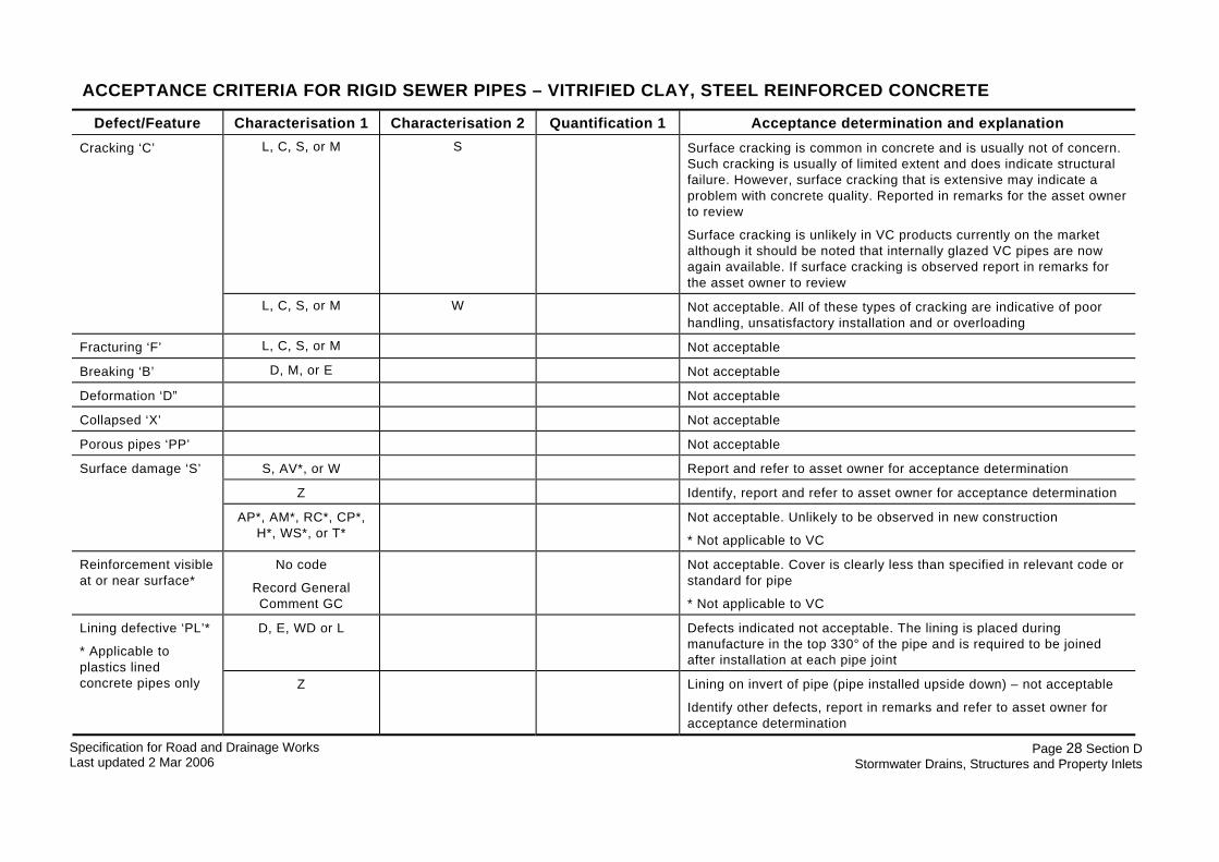
ACCEPTANCE CRITERIA FOR RIGID SEWER PIPES – VITRIFIED CLAY, STEEL REINFORCED CONCRETE
Defect/Feature Characterisation 1 Characterisation 2 Quantification 1 Acceptance determination and explanation L, C, S, or M S Surface cracking is common in concrete and is usually not of concern.
Such cracking is usually of limited extent and does indicate structural failure. However, surface cracking that is extensive may indicate a problem with concrete quality. Reported in remarks for the asset owner to review
Surface cracking is unlikely in VC products currently on the market although it should be noted that internally glazed VC pipes are now again available. If surface cracking is observed report in remarks for the asset owner to review
Cracking ‘C’
L, C, S, or M W Not acceptable. All of these types of cracking are indicative of poor handling, unsatisfactory installation and or overloading
Fracturing ‘F’ L, C, S, or M Not acceptable
Breaking ‘B’ D, M, or E Not acceptable
Deformation ‘D” Not acceptable
Collapsed ‘X’ Not acceptable
Porous pipes ‘PP’ Not acceptable
S, AV*, or W Report and refer to asset owner for acceptance determination
Z Identify, report and refer to asset owner for acceptance determination
Surface damage ‘S’
AP*, AM*, RC*, CP*, H*, WS*, or T*
Not acceptable. Unlikely to be observed in new construction
* Not applicable to VC
Reinforcement visible at or near surface*
No code
Record General Comment GC
Not acceptable. Cover is clearly less than specified in relevant code or standard for pipe
* Not applicable to VC
D, E, WD or L Defects indicated not acceptable. The lining is placed during manufacture in the top 330° of the pipe and is required to be joined after installation at each pipe joint
Lining defective ‘PL’*
* Applicable to plastics lined concrete pipes only Z Lining on invert of pipe (pipe installed upside down) – not acceptable
Identify other defects, report in remarks and refer to asset owner for acceptance determination

Specification for Road and Drainage Works Last updated 2 Mar 2006
Page 29 Section D Stormwater Drains, Structures and Property Inlets
Defect/Feature Characterisation 1 Characterisation 2 Quantification 1 Acceptance determination and explanation E Not acceptable. Should not occur in new pipeline
S or R Not acceptable
C Not acceptable
Deposits on wall or invert ‘DE’
W or Z Identify material, report in remarks and refer to asset owner for acceptance determination
Exfiltration ‘EX” Not acceptable. Exfiltration, if it is observed, is most likely associated with a joint defect or broken pipe
Infiltration ‘S’ S, D, R or G Not acceptable
Ingress of soil ‘ING’ Not acceptable
Roots ‘R’ T, F, or M Not acceptable. The presence of roots indicates a possible problem with installation at joints, poor quality concrete, cracks and/or fractures
‘L’ Not acceptable. If joint displacement exceeds maximum specified by manufacturer for the joint
‘R’ >5 mm for pipe sizes up to DN250
>10 mm for pipe sizes from above DN250 to DN500
>20 mm for pipe sizes above DN500
Not acceptable
Joint displacement ‘JD’
‘A’ Normally unacceptable on ‘straight’ pipelines (see maximum limits for ‘curved’ pipelines below). Report deflection and refer to asset owner for acceptance determination
For ‘curved’ pipelines using ‘pulled’ pipes the distance between the end of spigot and end of socket (adjoining pipe) at worst point and the angular deflection at the joint shall be within the range specified by manufacturer for the joint. Refer to asset owner for acceptance determination
Jointing material (seal) intrusion) ‘JI”
R or Z N, HH, HL, B or L Not acceptable
Point repair ‘RP’ L, I, S, H or IC Some techniques may not be acceptable in new pipelines. Report and

Specification for Road and Drainage Works Last updated 2 Mar 2006
Page 30 Section D Stormwater Drains, Structures and Property Inlets
Defect/Feature Characterisation 1 Characterisation 2 Quantification 1 Acceptance determination and explanation refer to asset owner for acceptance determination
Z Identify repair technique, report in remarks and refer to asset owner for acceptance determination
M or P Not acceptable Defective repair ‘RX’
B or Z Determine extent of ‘bellies’ or other defects, report and refer to asset owner for acceptance determination
B, M, I, J or C Not acceptable
Z Report and refer to asset owner for acceptance determination
Obstruction ‘OB’
P or S Report and refer to asset owner for acceptance determination
Water level ‘WL’ >15 mm or 5% whichever is the greater (no flow
from upstream and no blockage or
debris downstream)
Not acceptable above limit indicated
Water level above a nominal level may be caused by flow from upstream or a blockage, debris in the invert or some other feature downstream. It is not a defect in itself
It does indicate a defect. However, where there is no flow from upstream and there is no blockage or debris downstream. The most likely defect indicated in this situation is gradient misalignment i.e. one or more pipes have dropped below the grade and ponding has occurred
Defective junction ‘JX’
P, D, B, SR or BR Not acceptable
Connection ‘CN’ G or P Refer to asset owner specification/standard drawings for connections to determine acceptability
Defective connection ‘CX’
P, G, H, D, B, SR, BR Not acceptable
Intruding connection ‘CI’
Not acceptable

Specification for Road and Drainage Works Last updated 2 Mar 2006
Page 31 Section D Stormwater Drains, Structures and Property Inlets
ACCEPTANCE CRITERIA FOR FLEXIBLE SEWER PIPES – PVC, PE, POLYPROPYLENE, GRP (‘hobas’), DI (cement mortar lined), STEEL (‘sintakote’ lined)
Defect/Feature Characterisation 1 Characterisation 2 Quantification 1 Acceptance determination and explanation L, C, S, or M S Not acceptable. Not usually a feature of these pipe materials but may
be apparent in cement mortar linings and internal corrosion barrier (“gel-coat”) of GRP. Report as Lining defective ‘PL’
Cracking ‘C’
L, C, S, or M W Not acceptable. Not usually a feature of these pipe materials but where it does occur it would generally indicate excessive external loads from construction equipment
Fracturing ‘F’ L, C, S, or M Not acceptable
Breaking ‘B’ D, M, or E Not acceptable
Deformation ‘D” >5% after 60 days Not acceptable
Local or point deformation – no code
No code Record General Comment GC
Report and refer to asset owner for acceptance determination. An unusual feature with many possible causes
Collapsed ‘X’ Not acceptable
Porous pipes ‘PP’ Not acceptable. Not likely to be a feature of these pipes
W Report and refer to asset owner for acceptance determination.
Z Identify, where possible, report and refer to asset owner for acceptance determination
Surface damage ‘S’
CP or H Not acceptable. Unlikely to be observed in new construction
D●, E●* or B●* Not acceptable
* Applicable to internal corrosion barrier in GRP pipes ● Applicable to PE internal lining of ductile iron and steel pipes
Lining defective ‘PL’
Z Identify other defects, where possible, report and refer to asset owner for acceptance determination
E Not acceptable. Should not occur in new pipeline
S or R Not acceptable
Deposits on wall or in invert ‘DE’
C Not acceptable

Specification for Road and Drainage Works Last updated 2 Mar 2006
Page 32 Section D Stormwater Drains, Structures and Property Inlets
Defect/Feature Characterisation 1 Characterisation 2 Quantification 1 Acceptance determination and explanation W or Z Identify, where possible, report and refer to asset owner for acceptance
determination
Exfiltration ‘EX” Not acceptable. Exfiltration is most likely associated with a joint defect or broken pipe
Infiltration ‘S’ S, D, R or G Not acceptable
Ingress of soil ‘ING’ Not acceptable
Roots ‘R’ T, F, or M Not acceptable. The presence of roots indicates a possible problem with installation at joints, cracks and/or fractures
‘L’ Not acceptable. If joint displacement exceeds maximum specified by manufacturer for the joint
‘R’ >5 mm for pipe sizes up to DN250
>10 mm for pipe sizes from above DN250 to DN500
>20 mm for pipe sizes above DN500
Not acceptable
Joint displacement ‘JD’
‘A’ Normally unacceptable on ‘straight’ pipelines (see maximum limits for ‘curved’ pipelines below). Report deflection and refer to asset owner for acceptance determination
For ‘curved’ pipelines using ‘pulled’ pipes the distance between the end of spigot and end of socket (adjoining pipe) at worst point and the angular deflection at the joint shall be within the range specified by manufacturer for the joint. Refer to asset owner for acceptance determination
Jointing material (seal) intrusion) ‘JI’
R or Z N, HH, HL, B or L Not acceptable
L, I, S, H or IC Some techniques may not be acceptable in new pipelines. Report and refer to asset owner for acceptance determination
Point repair ‘RP’
Z Identify repair technique, report in remarks and refer to asset owner for acceptance determination
Defective repair ‘RX’ M or P Not acceptable
Specification for Road and Drainage Works Last updated 2 Mar 2006
Page 33 Section D Stormwater Drains, Structures and Property Inlets
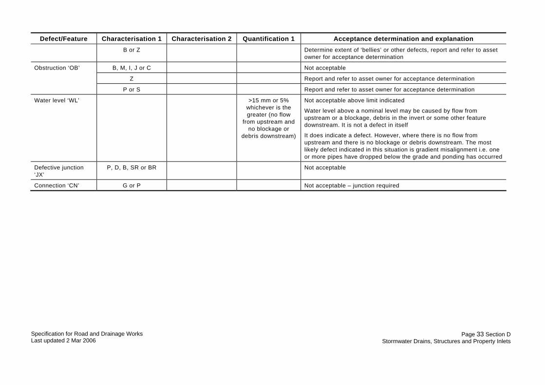
Defect/Feature Characterisation 1 Characterisation 2 Quantification 1 Acceptance determination and explanation
B or Z Determine extent of ‘bellies’ or other defects, report and refer to asset owner for acceptance determination
B, M, I, J or C Not acceptable
Z Report and refer to asset owner for acceptance determination
Obstruction ‘OB’
P or S Report and refer to asset owner for acceptance determination
Water level ‘WL’ >15 mm or 5% whichever is the greater (no flow
from upstream and no blockage or
debris downstream)
Not acceptable above limit indicated
Water level above a nominal level may be caused by flow from upstream or a blockage, debris in the invert or some other feature downstream. It is not a defect in itself
It does indicate a defect. However, where there is no flow from upstream and there is no blockage or debris downstream. The most likely defect indicated in this situation is gradient misalignment i.e. one or more pipes have dropped below the grade and ponding has occurred
Defective junction ‘JX’
P, D, B, SR or BR Not acceptable
Connection ‘CN’ G or P Not acceptable – junction required

Specification for Road and Drainage Works Last updated 2 Mar 2006
Page 34 Section D Stormwater Drains, Structures and Property Inlets
ACCEPTANCE CRITERIA PIPE AND FITTING CONFIGURATION – ALL SEWERS
The configuration of pipes and fittings in a new sewer is usually defined in design drawings, standard drawings and specifications. Compliance with some of these requirements may be determined by CCTV inspection. The inspector shall have a copy of design drawings, standard drawings and specifications applicable to the asset being inspected for reference in determining the acceptance of the following and other features. The following table describes some of the features that are to be examined for acceptance.
Feature Description Acceptance determination and explanation
Rocker pipes These a shorter pipes than the normal unit pipe length and are required by some asset owners adjacent to structures such as maintenance holes, other structures and concrete encasement
The purpose is to allow for differential settlement between the structure and the pipeline without cracking, fracturing or distortion of the pipe adjacent to the structure
The required length of rocker pipe and the configuration of pipes at the structure are specified in design drawings, standard drawings and or specifications for particular pipe materials
The inspector should record the distance at each joint adjacent to the structure to determine the length of the rocker pipe and report it in remarks
Length outside of tolerance of ± 150 mm of required length not acceptable – refer to asset owner for acceptance determination
Bends Bends occur in some sewers at changes of direction and or grade. In some cases compound bends (vertical and horizontal) may be encountered
In small diameters up to DN 225 bends are likely to be moulded or post-formed long radius. For ≥DN 225 it is likely that bends will be fabricated in a ‘lobster back’ with a series of mitre cuts and the pipes joined with epoxy, hot air welding or some other technique
Not acceptable if the camera unit cannot pass through the bend. In stormwater drains the bends must be traversable by the CCTV camera and transportation unit
Not acceptable if jointing materials at mitres intrude more than 10 mm into the pipe
The transition to bend from straight line must not exceed the angular deflection for the joint system used Record joint deflection if observable and refer to asset owner to assess for acceptance determination
Where the installation of the bend results in ponding the acceptance criteria applied for maximum water level in the previous tables shall also be applied
The distance at the start and finish of bends shall be recorded in the inspection report
Connections This is where another sewer to provide a service for a customer has been connected to the pipeline being inspected after the pipeline has been installed The connection is formed by making a hole in the original pipe and setting the connecting pipe in place
Not acceptable

Specification for Road and Drainage Works Last updated 2 Mar 2006
Page 35 Section D Stormwater Drains, Structures and Property Inlets
Feature Description Acceptance determination and explanation This feature is not part of new sewer construction
Junction A junction is a prefabricated fitting installed as part of the original construction or post construction by inserting the junction fitting in the pipeline
Junctions are provided to allow customers to connect house drains directly to the sewer or allow a property connection sewer to be extended to the customer’s property
Acceptable configurations of junctions should be specified by the asset owner
Not acceptable if configuration varies from asset owner’s specification/standard drawing
All junctions for direct customer connection are to provided with a PVC plain wall solvent weld socket with screwed cap or for VC, a plugged VC to PVC plain wall adaptor
Inspect each junction lateral and report compliance
Maintenance shaft
Provide access to the sewer for maintenance equipment but not person entry
This feature usually consists of an enlarged ‘tee’ section or spherical chamber constructed as part of the sewer, with a shaft of DN 225 extending to the surface
The ‘tee’ or chamber may be injection moulded PVC, rotational moulded PE or fabricated PVC and GRP
Maintenance shafts may have an integral bend or may have an adjoining (generally upstream) long radius bend
Maintenance shafts can have up to three inlets
Not acceptable if the CCTV camera and transportation unit cannot traverse through the maintenance shaft
The transition to maintenance shaft from bend or straight line must not exceed the angular deflection for the joint system used Record joint deflection if observable and refer to asset owner for acceptance determination