design safe side drains - department of roads
TRANSCRIPT
His Majesty’s Government of Nepal
Road Safety Notes 2
Design Safe Side Drains
D
Traffic Engineering and Safety Unitesign Branch, Department of Roads
Ministry of Works and Transport
November 1996 Kartik 2053
ROAD SAFETY NOTES
Road Safety Notes are produced by tile Traffic Engineering and Safety Unit of Department of
Roads as a means of increasing road safety awareness amongst highway engineers and others.
Some of the Notes provide information on aspects of the road accident situation Nepal, whilst
others give detailed technical advice on highway safety measures. The Traffic Engineering and
Safety Unit was set up in Balsakh 2052 to provide a road safety and traffic engineering service,
and is based in the Design Branch of the Department of Roads at Babarmahal, Kathmandu.
The Unit Head (telephone/fax 262843, e-mail: [email protected]) will be pleased to
receive comments and suggestions which will help improve the Road Safety Notes.

Contents
Summary 1
Overview 1
Planning 2
Design Aspects
(A) Discharge calculation 3
(B) Capacity of Drains 6
(C) Safety Aspects 8
(D) Maintenance Aspects 10
Recommended Drain Types 10
Appendix ‘‘A’’ 14
Appendix “B” 16

Summary Side drains are in integral part of roads and are an essential means of preventing structural
damage to the road. From general observation it is apparent that their design and construction
is not given enough thought in Nepal, resulting in problems. They are sized by ad hoc selection
of standard drawings without any calculations, resulting in expensive, oversized, unsafe drains.
Design of drainage ditches is not an easy task. We need drains that are large enough to
effectively cater for large discharge but deep drains can be unforgiving to pedestrians and
vehicles that stray into them. Gentle side slopes and shallow depths are safer to the traffic but
drains need to be deep enough to drain sub grade water. It is evident that while opting for a
most suitable drain compromises have to be made.
Careful planning is needed to achieve the most appropriate and safe section of side drains for
different terrain. Drainage design should take care of cross drainage, road surface drainage,
erosion control and Sub surface drainage.
The design of drains should be such that any vehicle falling in it should remain upright, be as
little damaged as, possible and recovered easily.
Earthen drains with gentle side slope (1:4) are effective in flat terrain. Dish type drains are
more forgiving than channel sections. Channel drains should ideally be no more than 300 mm.
deep (Absolute maximum of 450 mm). Deeper Channel drains should be covered. Shallow
“V”, Dish type, Tick drains or covered drains can function as footpath if necessary and also
provide extra width where roads are narrow.
Drains should also be easily maintainable by keeping at least 400 mm. wide flat bottom for
easy cleaning and providing self cleansing velocities.
Discharge calculation should be done to attain effective drain section and to avoid
unnecessarily large sections which are hazardous to traffic.
Final disposals should always be at stable water courses.
This document provides a guide for choosing and designing the most cost-effective and safe
drain for any situation.
Overview
While designing we should go for the most suitable option. It should effectively drain tile
Surface water, be easily maintainable, economic in cost, safe for traffic and other road Users.
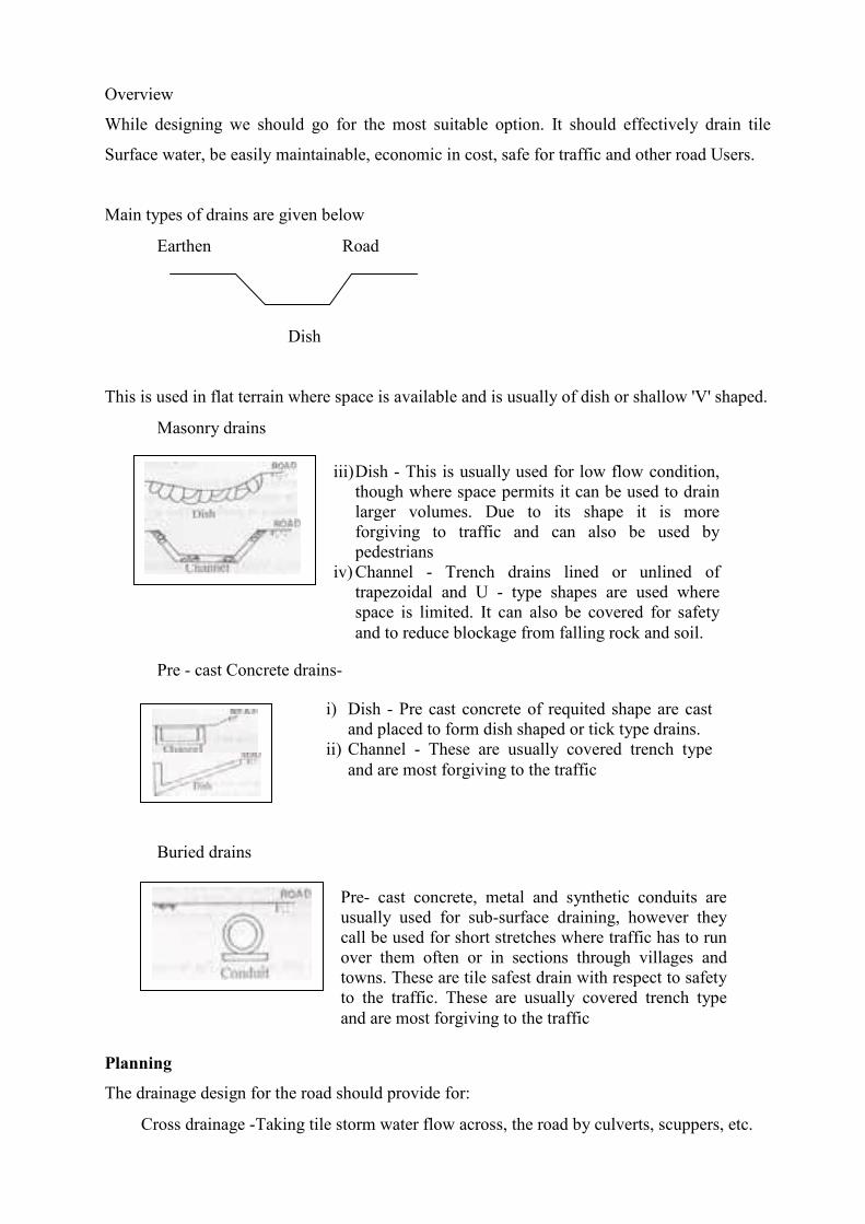
Main types of drains are given below
• Earthen Road
Dish
This is used in flat terrain where space is available and is usually of dish or shallow 'V' shaped.
• Masonry drains
• Pre - cast Concrete drains-
• Buried drains
Planning
The drainage design for the road should provide for:
• Cross drainage -Taking tile storm water flow across, the road by culverts, scuppers, etc.
iii) Dish - This is usually used for low flow condition, though where space permits it can be used to drain larger volumes. Due to its shape it is more forgiving to traffic and can also be used by pedestrians
iv) Channel - Trench drains lined or unlined of trapezoidal and U - type shapes are used where space is limited. It can also be covered for safety and to reduce blockage from falling rock and soil.
i) Dish - Pre cast concrete of requited shape are cast and placed to form dish shaped or tick type drains.
ii) Channel - These are usually covered trench type and are most forgiving to the traffic
Pre- cast concrete, metal and synthetic conduits are usually used for sub-surface draining, however they call be used for short stretches where traffic has to run over them often or in sections through villages and towns. These are tile safest drain with respect to safety to the traffic. These are usually covered trench type and are most forgiving to the traffic
• Road surface drainage -Draining the storm water falling oil (lie roadway by ditches,
chutes, etc.
• Erosion control -Protecting the roadway and adjoining properties from erosion by ditches,
intercepting channels, slope lining, riprap, etc.
• Sub-surface draining -The drains should not hinder in sub-surface draining but should
help draining tile sub- surface Water.
Careful planning of' alignment and other features will help in achieving better side drains. In
flat and easy terrain side drains are usually designed for draining water from road formation
only, whereas in hilly terrain they have to provide for water coming from adjacent watershed
area and provide for erosion control.
Where space permits the drains and its outlets should be constructed away from the load edge.
This not only provides space for future expansion but also provide recovery space for straying
vehicles. Usually scouring problems are more acute near the outlets which can not only be
hazardous to tile road but also to tile traffic.
Final disposals should only be at stable dry water courses or running streams and not at any
other location. If water is disposed at other places it can destabilize the area causing severe
environmental damage.
Surveying the outlet gully to estimate if it can safety contain the increased discharge, and if it
requires, strengthening is also essential.
Frequency of drain outlets on hill roads should be as high as possible as -
• The drain section would be smaller and hence more forgiving to tile traffic and
pedestrians.
• Long side drains (in excess of 100 in. without outlets) in high rainfall area creates
massive damage if they become blocked by debris and landslide.
• Comparatively lower How reduces the risk of damage to the outlets and the drain itself.
Lower volume of discharge means smaller drain section and, though more in numbers,
simpler and smaller culverts are adequate and hence would also be cheaper.
• Final disposals should be at stable dry water courses or running streams.
In hill roads where rainfall is heavy, it is recommended that culverts or other suitable type of
cross drainage is provided every 60 - 100 m with proper disposals.
Appropriate camber in both the cross section of road and shoulder is required for tile drain to
function properly. Nepal Road Standards should be followed for appropriate camber.
Drain should not be above the road surface if they are to function. Care should be taken at the
time of construction to oversee the correct slope and the invert level to ensure this.
In hilly road side drains on valley side should be avoided as far as possible; provided only iii
exceptional cases and by properly managing the discharge from the outlet as stated earlier.
In hilly road the valley side slope is in existence before the road was built and hence without
drains it should be stable enough to drain any flow coming oil to it due to rain. It just needs to
be ensured that water is not collected and discharged at one point of the slope but should be
drained all along the side of the road. When it is allowed to discharge through one point it can
severely damage the slope. Therefore drains on valley side would only shift tile aggravation to
a new location without solving the problem at the first site. If it is unavoidable, down the
discharge should be properly trained down to tile end point of the Outlets.
Variation in the cross section is another aspect which is often ignored. Smaller drain at the
starting Point gradually increased towards the outlet not only reduces the cost but also
enhances safety due to smaller drain size. The outlet of the drain should be dropped as far as
possible from file road side so that the larger section drain is further away from the road.
Design Aspects
(A) Discharge Calculation
Designs of side drains and culverts based oil guesswork, do save-time and effort in the design,
Process, but usually create problems that subsequently involve more time, effort and resources.
Simple calculation will in most instances show that a smaller drain is adequate to effectively
drain off the road and adjacent area.
Design Flood and Its Frequency
The first step in clesigimig facilities is to estimate the quantity of water likely to be drained.
Drainage facilities should have sufficient capacity to carry off safely not only peak runoffs,
which occur frequently, say several times a year, but also larger runoffs, occurring less
frequently. For a major highway linking major economic centers, where disruption of traffic,
caused by damage or washout of culverts, may not be acceptable, a peak runoff that recurs
every 25 years needs to be considered. In contrast; for a rural highway where some minor
traffic disturbances can he tolerated, a peak runoff that recurs every 10 years is sufficient.
However, where serious damage would result from erosion caused by the inadequate capacity
of drainage facilities, the less frequent peak runoffs would have to be used.
It is not practicable to design for a maximum probable flood to cater for the worst possible
flood, as the capital costs increase rapidly with the increment of the peak runoff.. In order to
economize oil Construction costs, frequency of' flood is selected for longer or shorter return
periods, depending upon the importance of the structure.
The design flood is a flood corresponding to the selected return period. It is not economical to
over design. It should be kept in mind that the flooding of tile road for short period of time
after a big storm is acceptable where it is unlikely to damage the road by such event.
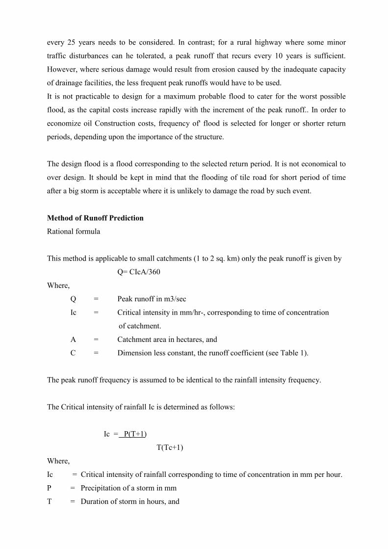
Method of Runoff Prediction
Rational formula
This method is applicable to small catchments (1 to 2 sq. km) only the peak runoff is given by
Q= CIcA/360
Where,
Q = Peak runoff in m3/sec
Ic = Critical intensity in mm/hr-, corresponding to time of concentration
of catchment.
A = Catchment area in hectares, and
C = Dimension less constant, the runoff coefficient (see Table 1).
The peak runoff frequency is assumed to be identical to the rainfall intensity frequency.
The Critical intensity of rainfall Ic is determined as follows:
Ic = P(T+1)
T(Tc+1)
Where,
Ic = Critical intensity of rainfall corresponding to time of concentration in mm per hour.
P = Precipitation of a storm in mm
T = Duration of storm in hours, and
Tc = Time of concentration in hrs.
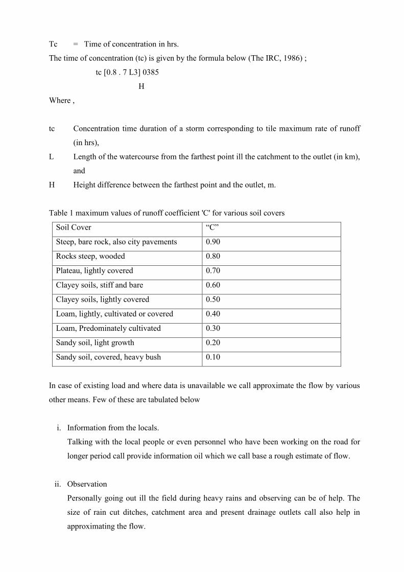
The time of concentration (tc) is given by the formula below (The IRC, 1986) ;
tc [0.8 . 7 L3] 0385
H
Where ,
tc Concentration time duration of a storm corresponding to tile maximum rate of runoff
(in hrs),
L Length of the watercourse from the farthest point ill the catchment to the outlet (in km),
and
H Height difference between the farthest point and the outlet, m.
Table 1 maximum values of runoff coefficient 'C' for various soil covers
Soil Cover “C”
Steep, bare rock, also city pavements 0.90
Rocks steep, wooded 0.80
Plateau, lightly covered 0.70
Clayey soils, stiff and bare 0.60
Clayey soils, lightly covered 0.50
Loam, lightly, cultivated or covered 0.40
Loam, Predominately cultivated 0.30
Sandy soil, light growth 0.20
Sandy soil, covered, heavy bush 0.10
In case of existing load and where data is unavailable we call approximate the flow by various
other means. Few of these are tabulated below
i. Information from the locals.
Talking with the local people or even personnel who have been working on the road for
longer period call provide information oil which we call base a rough estimate of flow.
ii. Observation
Personally going out ill the field during heavy rains and observing can be of help. The
size of rain cut ditches, catchment area and present drainage outlets call also help in
approximating the flow.
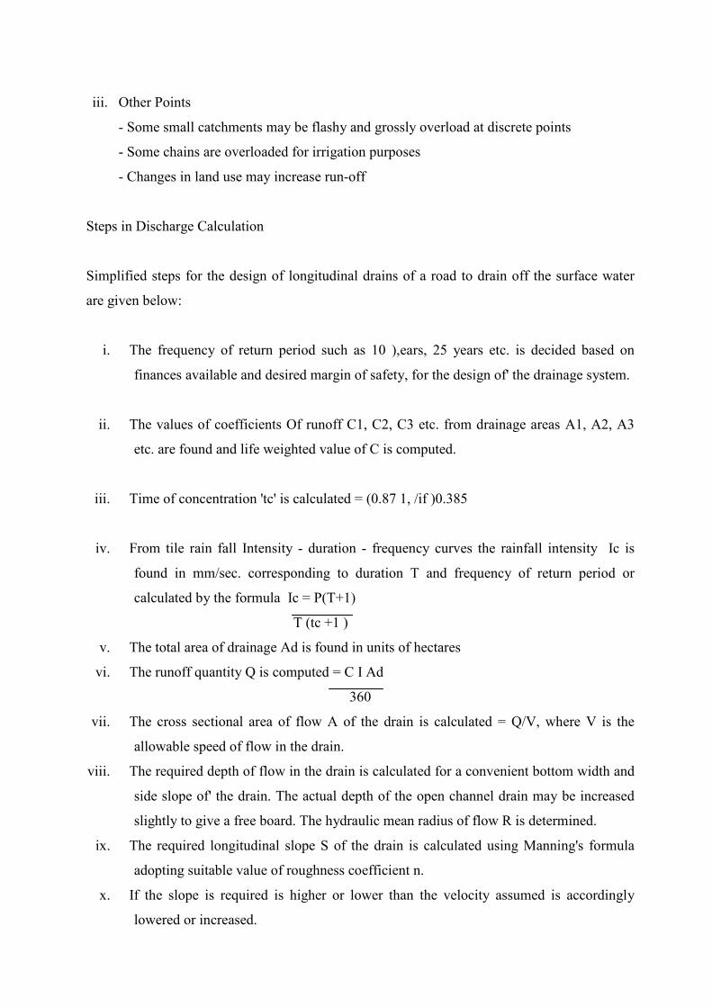
iii. Other Points
- Some small catchments may be flashy and grossly overload at discrete points
- Some chains are overloaded for irrigation purposes
- Changes in land use may increase run-off
Steps in Discharge Calculation
Simplified steps for the design of longitudinal drains of a road to drain off the surface water
are given below:
i. The frequency of return period such as 10 ),ears, 25 years etc. is decided based on
finances available and desired margin of safety, for the design of' the drainage system.
ii. The values of coefficients Of runoff C1, C2, C3 etc. from drainage areas A1, A2, A3
etc. are found and life weighted value of C is computed.
iii. Time of concentration 'tc' is calculated = (0.87 1, /if )0.385
iv. From tile rain fall Intensity - duration - frequency curves the rainfall intensity Ic is
found in mm/sec. corresponding to duration T and frequency of return period or
calculated by the formula Ic = P(T+1)
T (tc +1 )
v. The total area of drainage Ad is found in units of hectares
vi. The runoff quantity Q is computed = C I Ad
360
vii. The cross sectional area of flow A of the drain is calculated = Q/V, where V is the
allowable speed of flow in the drain.
viii. The required depth of flow in the drain is calculated for a convenient bottom width and
side slope of' the drain. The actual depth of the open channel drain may be increased
slightly to give a free board. The hydraulic mean radius of flow R is determined.
ix. The required longitudinal slope S of the drain is calculated using Manning's formula
adopting suitable value of roughness coefficient n.
x. If the slope is required is higher or lower than the velocity assumed is accordingly
lowered or increased.
xi. Once the tentative section has been obtained than changes can be made as per
requirements as shown in the example in the appendix “A”.
(B) Capacity of Drains
Flow in open channels is classified as steady and unsteady. Unsteady flow occurs when the
quantity of water, cross sections of flow, and the slope of the carrying channels are changing.
However, for simplicity of hydraulic calculations, flows in road drainage channels are treated
as if occurring under steady conditions.
Steady flow can either be uniform or non-uniform (varied).
a) Uniform Flow
Uniform flow will take place when tile cross section, roughness, and slope of the channel
remain constant over the stretch under consideration. The errors involved in assuming uniform
flow in drainage channels me relatively small compared to errors in establishing design peak
flows, hence drainage channels with constant cross section, roughness, and slope are often
designed as, uniform flow channels.
The most widely, used equation for uniform flow is tile following Manning Equation :
V = I R 2/3 S 1/2
n
Where,
V - Velocity, m/sec,
n - Rugosity coefficient (see Table 2)
R - hydraulic radius, m, (A/P)
A - Wetted cross sectional area of flow, in 2
P - Wetted perimeter, m and
S - Slope of the channel m/m.
After finding velocity from the above equation, tile discharge of the channel call be established
by:
Q = AV
Where,
Q - Flows, m3 /sec,
A - Cross sectional area of flow, m2 and
V - Velocity of flow, m/sec.
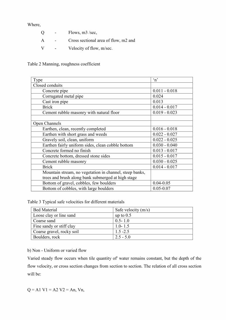
Table 2 Manning, roughness coefficient
Type ‘n’ Closed conduits
Concrete pipe 0.011 - 0.018 Corrugated metal pipe 0.024 Cast iron pipe 0.013 Brick 0.014 - 0.017 Cement rubble masonry with natural floor 0.019 - 0.023
Open Channels Earthen, clean, recently completed 0.016 - 0.018 Earthen with short grass and weeds 0.022 - 0.027 Gravely soil, clean, uniform 0.022 - 0.025 Earthen fairly uniform sides, clean cobble bottom 0.030 - 0.040 Concrete formed no finish 0.013 - 0.017 Concrete bottom, dressed stone sides 0.015 - 0.017 Cement rubble masonry 0.030 - 0.025 Brick 0.014 - 0.017 Mountain stream, no vegetation in channel, steep banks, trees and brush along bank submerged at high stage
Bottom of gravel, cobbles, few boulders 0.04-0.05 Bottom of cobbles, with large boulders 0.05-0.07
Table 3 Typical safe velocities for different materials
Bed Material Safe velocity (m/s) Loose clay or line sand up to 0.5 Coarse sand 0.5- 1.0 Fine sandy or stiff clay 1.0- 1.5 Coarse gravel, rocky soil 1.5 -2.5 Boulders, rock 2.5 - 5.0
b) Non - Uniform or varied flow
Varied steady flow occurs when tile quantity of' water remains constant, but the depth of the
flow velocity, or cross section changes from section to section. The relation of all cross section
will be:
Q = A1 V1 = A2 V2 = An, Vn,
The above equation is called Equation of Continuity.
The cross sectional area should be sufficient for effective drainage from carriageway and the
adjacent area. Though we do not want eroding velocity adequate longitudinal slope should be
provided so that water does not accumulate and percolate to the subgrade.
However ditches do not need to be water tight and, indeed, it is better if they are not water
tight on the side nearest the carriageway. Even in areas of tropical rainfall they will be dry for
much longer then they are wet. If the side of the ditch is porous, evaporation takes place
rapidly and dries out not only water which has percolated sideways from the ditch into the
subgrade but also any which has percolated vertically into the subgrade from cracks in the
surface of the pavement.
C) Safety Aspects -
a) Vehicles
Design of drains should be such that any vehicle which falls into them should:
• remain upright (over turning or partial overturning can crush the passenger
compartment, causing serious injury to the occupants.)
• be as little damaged as possible.
• be capable of being easily recovered.
Earthen Drains -
Slopes on the side of the drain nearest the road should not be more than 4:1 and preferably
shallower if feasible, as this will make it possible for drivers of out-of-control vehicles to bring
them to a stop without serious damage or injury.
Channel drains-
Usually drain depth below 300 min is forgiving to traffic, the absolute maximum for
uncovered drain should be 450 mm. Larger depths can be avoided by either increasing the
width where possible or even using half the section (up to the crest) of the paved road for
limited duration to let as drain but care is needed to prevent any rut or erosion. Maximizing the
width and minimizing the depth should always be the priority; however it should be deep
enough to allow draining of pavement underlayers. Drain depth can be designed between these
limits. Bottom of the drains must be flat to help vehicle stay upright.

Masonry line
crossing each
tendency to e
fill side is not
as it can caus
inadequate be
Raising the ro
from falling
developing of
Example of R
Dish Drains -
As this is usu
straying vehic
Example of Safe Channel Drain
d drains should be strong enough to withstand the loads exerted by vehicles
other and traveling very near or even over the wall of the drain. There is a
rect side walls in uncoursed random rubble and the sides of the walls facing the
properly constructed as they are finally covered up. This needs to be dissuaded
e accidents when vehicles stray close to the drains, and the wall collapses due lo
aring strength.
adside wall of the drain as a low kerb (see illustration below) can help vehicles
into it. However openings should be spaced at maximum one meter to avoid
puddles due to uneven micro topography of the road surface.
aised Kerb Channel Drain
ally shallow and with mild side slopes it is more forgiving to traffic and any
les can recover to come back on the road.
SLOPES
RAISED KERBS
OPERNINGS FOR DRAINING
Covered & Closed Drains –
These drains are wholly safe to the traffic if the cover stab is built strong enough to take the
weight of the traffic. Size and weight of slab should be practicable for future maintenance i.e.,
slat) weighing around 50 Kgs. that can be lifted by two labours is practical.
b) Pedestrians
Where no footpath exists for pedestrian use tile shape or design of the drain should be such
that it could be used by pedestrians. Shallow 'V', dish or covered type drain can function as
footpath.
Drains on roads through villages and towns should be dish type, or covered or closed drains. In
narrow road where space is limited cither covered drain, or if flow is low, dish drain is
preferable, so that it call be used by both tile vehicle and pedestrians when necessary for
safety.
(D) Maintenance Aspects -
• Drain dimension should be such that it call he both easily cleaned and requires minimal
labour to keel) it clean i.e, tile velocity of the flow should be self cleansing, refer to
Table no. 3.
• Proper design of' catch pits and treatment of slopes along tile drain ill hilly roads is
required so that minimum amount of debris comes into the drain.
• Provision of check dams and rip rap oil sides at various stretches of drain in Terai road
may be necessary to prevent scouring.
The lining of the drain should be strong enough, and the velocity of flow low enough so that
there is very little wear.
These drains should also have a velocity that is between eroding and self cleansing to prevent
excessive erosion and percolation into subgrade.
Drystone lining is a step up from earthen drain. The side & invert of the drain is lined with
drystone. Though cheaper than masonry or other types of linings, due to high cost of
maintenance, lack of structural, strength and excessive percolation of water into subgrande it is
not preferred in heavy traffic highways. It can be used ill rural or side roads, or even
temporarily in important roads.
Pre-cast concrete drains are more durable but the initial cost is very high. Masonry drains with
proper quality control would be a better option.
Drains need to be kept clean for proper functioning. Open drains are easier to clean than closed
ones but it' properly designed i.e. have sufficient longitudinal slope to induce self cleaning
velocity, have catch pits, and are covered efficiently to prevent debris from entering the drain,
closed ones ire equally maintainable. In areas where there are rockfalls and landslides covering
the drains will prevent blockage.
The flat bottom dimension of a channel drain should be at least 400 mm to allow for cleaning
with shovels.
Recommended Drain Types -
The detail design showing, tile calculation of drain size is illustrated ill Appendix ‘A’. The
dimension of, side walls, base, thickness of slab etc. is site specific and should he determined
by the designers themselves.
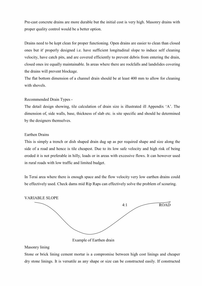
Earthen Drains
This is simply a trench or dish shaped drain dug up as per required shape and size along the
side of a road and hence is tile cheapest. Due to its low safe velocity and high risk of being
eroded it is not preferable in hilly, loads or in areas with excessive flows. It can however used
in rural roads with low traffic and limited budget.
In Terai area where there is enough space and the flow velocity very low earthen drains could
be effectively used. Check dams mid Rip Raps can effectively solve the problem of scouring.
VARIABLE SLOPE
4:1 ROAD
Example of Earthen drain
Masonry lining
Stone or brick lining cement mortar is a compromise between high cost linings and cheaper
dry stone linings. It is versatile as any shape or size can be constructed easily. If constructed
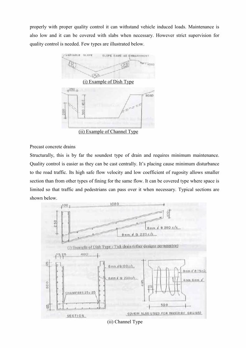
properly with proper quality control it can withstand vehicle induced loads. Maintenance is
also low and it can be covered with slabs when necessary. However strict supervision for
quality control is needed. Few types are illustrated below.
Precast concrete drains
Structurally, this is by far the soundest type of drain and requires minimum maintenance.
Quality control is easier as they can be cast centrally. It’s placing cause minimum disturbance
to the road traffic. Its high safe flow velocity and low coefficient of rugosity allows smaller
section than from other types of fining for the same flow. It can be covered type where space is
limited so that traffic and pedestrians can pass over it when necessary. Typical sections are
shown below.
(i) Example of Dish Type
(ii) Example of Channel Type
(ii) Channel Type
Alternate type of channel type drain is to have cast-in-situ base with brick walls, cast-in
capping and precast cover slab which would be cheaper than the above type.
Buried drains
Along with cement masonry and precast concrete drains we can also have fabricated closed
conduits for draining. It’s high cost and difficulty in keeping it clear of debris is the main
constrains against using it as side drains. It is usually used for sub surface drainage. We could
however use it for short stretches where space is limited for closed drain and traffic requires to
flow over the drain for prolonged period of time.
In places where there is restriction of space or when road formation is in cutting construction
of' deep open drain may be undesirable. In such cases we can also use drainage trenches as
shown below.
Appendix 'A'
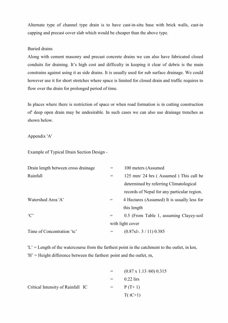
Example of Typical Drain Section Design -
Drain length between cross drainage = 100 meters (Assumed
Rainfall = 125 mm/ 24 hrs ( Assumed ) This call be
determined by referring Climatological
records of Nepal for any particular region.
Watershed Area 'A' = 4 Hectares (Assumed) It is usually less for
this length
‘C’ = 0.5 (From Table 1, assuming Clayey-soil
with light cover
Time of Concentration ‘tc’ = (0.87xl-. 3 / 11) 0.385
'L’ = Length of the watercourse from the farthest point in the catchment to the outlet, in km,
'H’ = Height difference between the farthest point and the outlet, m,
= (0.87 x 1.13 /60) 0.315
= 0.22 lirs
Critical Intensity of Rainfall IC = P (T+ 1)
T( tC+1)

Where,
IC = Critical intensity of rainfall corresponding to time of concentration in mm/hour.
P = Precipitation of a storm in mm, 125mm
T = Duration of storm in hours, 24 hrs
Tc = Time of concentration in hrs, 0.22 hrs
Therefore “IC “ = 125 (24+1)
24 (0.22+1)
= 106.73
Discharge ‘Q’ = C Ic-A
360
= 0.6 m3 /see,
Let ‘V’ = 4 m/sec, which is safe for masonry lined drain
Then Area of drain 'A' = 0.6 /4
= 0. 15 m 2
If the section is shown.
Then 0.15 = 0.4 d + 2d 2
Therefore d = 0.2 m
Hydraulic Radius R = Wetted cross sectional area flow, m2 'A'
Wetted Perimeter, m, 'P'
= 0.2 x 0.4 + 1/2 x 0.2 x 4 x 0.2
0.2 + 0.4 + ( 0.2 2 + 0.82 )1/2
= 0.112
Required slope of drain 'S' = ( Vn / R2/3 )2
= (4 x 0.03/0.1122/3)2
= 27%
As the road gradient is 8% this slope is not feasible, therefore let tile flow velocity be 2.5
m/sec
Then, ‘A’ = 0.6 / 2.5
= 0.24m2
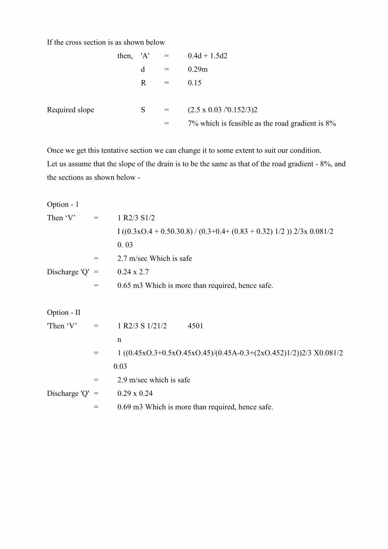
If the cross section is as shown below
then, 'A' = 0.4d + 1.5d2
d = 0.29m
R = 0.15
Required slope S = (2.5 x 0.03 /'0.152/3)2
= 7% which is feasible as the road gradient is 8%
Once we get this tentative section we can change it to some extent to suit our condition.
Let us assume that the slope of the drain is to be the same as that of the road gradient - 8%, and
the sections as shown below -
Option - 1
Then ‘V’ = 1 R2/3 S1/2
I ((0.3xO.4 + 0.50.30.8) / (0.3+0.4+ (0.83 + 0.32) 1/2 )) 2/3x 0.081/2
0. 03
= 2.7 m/sec Which is safe
Discharge 'Q' = 0.24 x 2.7
= 0.65 m3 Which is more than required, hence safe.
Option - II
'Then ‘V’ = 1 R2/3 S 1/21/2 4501
n
= 1 ((0.45xO.3+0.5xO.45xO.45)/(0.45A-0.3+(2xO.452)1/2))2/3 X0.081/2
0.03
= 2.9 m/sec which is safe
Discharge 'Q' = 0.29 x 0.24
= 0.69 m3 Which is more than required, hence safe.

Good example of safe, efficient drain design on Dharan- Dhankuta roads.
This drain through Gajuri village should have been covered for pedestrian and vehicle safety
Deep Triangular – shaped drains like this are hazardous.
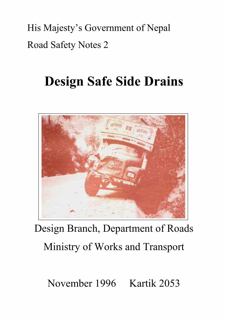
Vehicle straying into side like that shown above tend to overturn causing severe damage.

Steep side of this earthen “V” drain may have caused the vehicle to overturn.