economical and safe design for low-traffic long-roads
TRANSCRIPT

Journal of Electrical and Electronic Engineering 2020; 8(5): 117-126 http://www.sciencepublishinggroup.com/j/jeee doi: 10.11648/j.jeee.20200805.11 ISSN: 2329-1613 (Print); ISSN: 2329-1605 (Online)
Economical and Safe Design for Low-Traffic Long-Roads Illumination Control System by Using Image Recognition Technique
Muhammad M. A. S. Mahmoud*, Leyla Muradkhanli
Process Automation Engineering Department, Baku Higher Oil School, Baku, Azerbaijan
Email address:
*Corresponding author
To cite this article: Muhammad M. A. S. Mahmoud, Leyla Muradkhanli Name. Economical and Safe Design for Low-Traffic Long-Roads Illumination Control
System by Using Image Recognition Technique. Journal of Electrical and Electronic Engineering. Vol. 8, No. 5, 2020, pp. 117-126.
doi: 10.11648/j.jeee.20200805.11
Received: October 14, 2020; Accepted: October 23, 2020; Published: November 11, 2020
Abstract: The paper covers analysis and investigation of lighting automation system in low traffic roads. The main objective
is to provide optimal solution between expensive safe design utilizes continuous lighting at night for the complete road, or
sacrifice the safety to minimize the cost of energy consumption by relying on using vehicles lighting in low traffic road
designed without lighting systems. Each of these two scenarios is extremely significant issue and contradicting to each other
from economic point of view. By taking into account both of these factors, smart lighting control system is proposed using
Image Recognition Technique. In this proposal, the road is sectionalized into zones. By using motion sensors and Infra-Red
cameras distributed and installed in each zone, any moving object can be detected and its image can be captured and analyzed
using Image Recognition Technique to check whether the object is a vehicle or not. Matlab code is written and tested using
different images to validate the code output. In case a vehicle is detected, the control system of the road lighting illuminates
only the zone that the vehicle passes through. Economic analysis is provided in this paper to support the value of using this
design of lighting control system. “Saving Norm” of $1,171.19/km/Year is calculated for the proposed system. This “Saving
Norm” is a good index to supports project management for both project decision makers and for cash-flow controllers.
Keywords: Road Lighting Control, Road Lighting Automation, Vehicle Image Recognition, Smart Grid, Power Management,
Low Traffic Roads
1. Introduction
Various road classifications are existed in terms of traffic.
Principal arterials, minor arterials, rural collectors, local roads
and very low-volume roads, and the last is what our concern in
this paper. Statistically, for low-traffic roads the flow rate of
the vehicles is assumed to be 400 vehicles per day [1]. In low
these roads, even simple lighting system is not installed mostly,
and authorities rely on vehicle lights put human life and
valuable product transported under the risk. The main reason
of non-lighting system is to save the energy. However, fully
lightened roads cause wastage of electricity as one vehicles
may appear every three or four hours and even more during
the night time. Each of these two scenarios is extremely
significant issue.
Several researchers did some projects and published their
work related to this topic, however, none of them has
considered the lighting automation system on low traffic road.
Articles are mainly related to smart or automated street
lighting systems. In the following paragraphs, several
researches' results is discussed, and main points are drawn into
attention.
P. V. K. Bhangdiya suggests to use two sensors in order to
consume less power with maximized efficiency of a system is
proposed. Light Dependent Resistor (LDR) sensor is utilized
to measure the sun light intensity to control the switching
action of LED streetlights, and Passive Infrared Resistor (PIR)
motion sensor is used for changing the intensity of LED light
when there is no motion of object at mid-night on street then
all the streetlights are dimmed [2]. However, Noor Lina Ramli

118 Muhammad M. A. S. Mahmoud and Leyla Muradkhanli Name: Economical and Safe Design for Low-Traffic Long-Roads Illumination Control System by Using Image Recognition Technique
indicates that LDR and PIR sensor are used for same purpose,
but without dimming the light, just switched on or off [3].
Sindhu. A. M worked on this topic using Infrared Resistor (IR)
sensors which measure the heat of an object as well as detects
the motion, in contrast to what previous researchers did [4].
They developed the system using Arduino Uno R3 while Ms.
M. Kokilavani, achieved the same by Raspberry Pi 3 micro
controller [5].
Faiz Ansari offered Zigbee Based Smart Street Light
Control System Using LabVIEW. Here, movement is detected
by motion sensors, communication between lights is enabled
by Zigbee technology. So, when a passer-by is detected by a
motion sensor, it will communicate this to neighboring
streetlights, which will brighten so that people are always
surrounded by a safe circle of light [6].
Aman Kumar Akash developed Intelligent Street Lighting
System Using GSM technology. The aim is to achieve the
energy saving and autonomous operation on economical
affordable for the streets by installing chips on the lights.
These chips consist of a micro-controller along with various
sensors like CO2 sensor, fog sensor, light intensity sensor,
noise sensor and GSM modules for wireless data transmission
and reception between concentrator and PC. The emissions in
the atmospheres would be detected along with the
consumption of energy and any theft of electricity [7].
Automatic street-light control system using wireless sensor
networks is proposed by. D. SA. S. Rajasri. The system
contains lamp station and base station. Each lamp station
consists of Arduino Uno board as microcontroller, PIR sensor,
emergency switch, LDR sensor, nRF24L01 transceiver,
ultrasonic sensor, relay, LED light and a solar panel as energy
source. The base station consists of Raspberry Pi as processor,
nRF24L01 transceiver, and a GSM module. The automatic
streetlight turns on under three conditions. Firstly, when PIR
sensor detects a human or a moving object vehicle LED light
is turned on. Secondly, an ultrasonic sensor is used to detect
distance objects and turn on the light accordingly. Lastly, a
switch is included for manual operation in case of
maintenance work. The LDR sensor is included to measure the
light intensity for identification of the day and night. There
nRF24L01 wireless transceiver transmits the sensor
information and the light status to the Raspberry web server to
upload on the web page. Also, it receives commands sent from
the web page to turn on or off the light at a particular node.
The entire system is powered using solar cells making it more
energy efficient [8].
Muhammad M. A. S. Mahmoud tried to solve the problem
of high operational cost of low traffic light that use HPS
lighting by using LED light fitting instead of HPS luminaries
[9].
Many real projects have been done on this area, but few of
them are related to this topic exactly. Most of them consider
street, campus, parking, park or any small area lighting system.
The rest of them is devoted to road light and control systems.
Some of them will be analysed, discussed and compared [10,
11].
From the above literature review, firstly, all systems
mentioned above used LDR sensor to sense night-time to
operate the control system itself. In the system prosed in this
paper, the same day/night sensor idea is also use to know exact
hours of night-time or any dark time during the day time due
to heavy cloud or any other reasons.
Secondly, all systems above have used motion sensors to
detect the object movement whatever this object is, and hence
control the lights in terms of switching ON/OFF or dimming.
IR sensors and PIR sensor were the preferred sensors used to
detect the object. These type of sensors detect mainly warm
object and their movement. But, for the suggested system in
this paper that need to be used for low traffic road, movement
of only vehicle is needed to be recognised and hence switch on
the light or dim them. The proposed system need to be
designed to avoid any other motion such as animals, birds, or
other objects which may be detected by IR or PIR sensors as
this unnecessary detection of motion can cause unjustified
energy consumption. Therefore, it is needed to give new
approach to tackle with such problems. New approach could
be to add the night vision smart camera to the system in order
to recognize only the vehicles among all other objects that the
camera detects.
Thirdly, some systems control the illumination by
measuring the intensity of the objects movement and change
the dimming of the lights accordingly. But for illumination
system of low traffic roads, the intensity of the vehicles is
continuously very low, and hence dimming technique is not
effective solution.
Fourth, using LED light continuously operate during the
night for low traffic roads can reduce the cost of illuminating
the road compared with any other HID lighting, but still this is
not best solution because the utilization of this system by this
operational philosophy is not an efficient utilization because
most of the time the light is ON unnecessary
Fifth, in general, previous researches have been done on
lighting automation system for the roads which serve both
pedestrians and vehicles. But, this paper tries to design
automation lighting system for long road with low traffic,
where no need to switch on the lights for movement of any
object except the vehicles
In this paper, efficient, safe and cost effective solution to
design automated lighting system suitable for long roads with
low-traffic is provided. In section 2, description of the entire
system design is discussed. Section 3 illustrates the
methodology and the programing of vehicles recognition
using camera images. Section 4 provides economic analysis
for the proposed system. Conclusion is given in Section 5.
2. System Design Description
Lighting automation system in low traffic roads is intended
to implement in the illuminated roads. It is supposed to have
source power supply, feeder pillar with controller, light poles
with day/night sensor. Such conventional system can be
upgraded by new automated system. The methodology of
lighting automation system in low traffic roads is achieved by
applying the moving object recognition technique using
Journal of Electrical and Electronic Engineering 2020; 8(5): 117-126 119
cameras. Firstly, the road is sectionalized into several zones.
Each zone depends on how much distance is existed between
two feeder pillars, typically 400 meters. So, light poles in each
zone will be switch on/off together. It means that each zone
will have its feeder pillar (control panel) with controller,
day/night sensor, motion sensor, and camera. Night vision
cameras are installed on the road in such way to detect the
vehicle arrival-to and departure-from each zone. The
controller is designed to illuminate only the zones in which the
vehicle is detected. The type and span of the zone are
calculated based on the road design considering straight spans
and roundabout.
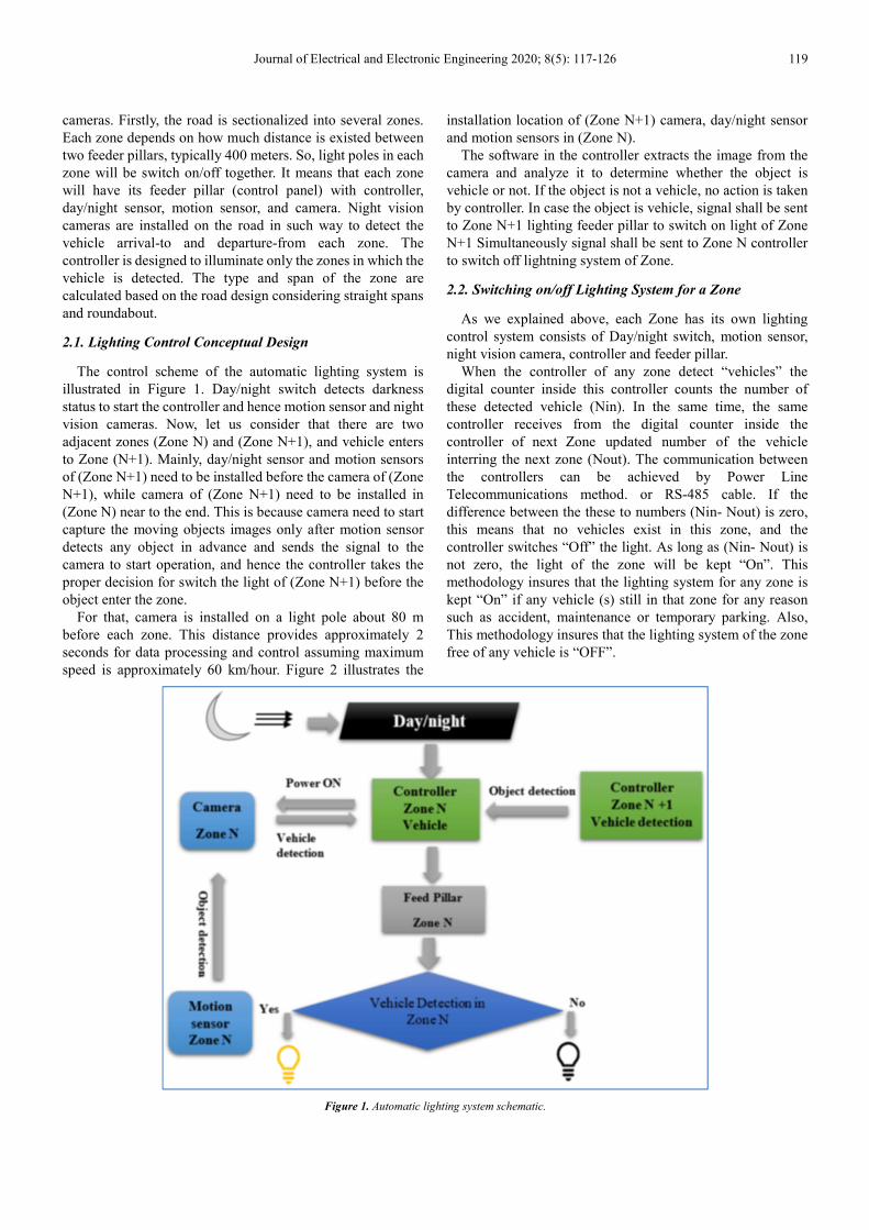
2.1. Lighting Control Conceptual Design
The control scheme of the automatic lighting system is
illustrated in Figure 1. Day/night switch detects darkness
status to start the controller and hence motion sensor and night
vision cameras. Now, let us consider that there are two
adjacent zones (Zone N) and (Zone N+1), and vehicle enters
to Zone (N+1). Mainly, day/night sensor and motion sensors
of (Zone N+1) need to be installed before the camera of (Zone
N+1), while camera of (Zone N+1) need to be installed in
(Zone N) near to the end. This is because camera need to start
capture the moving objects images only after motion sensor
detects any object in advance and sends the signal to the
camera to start operation, and hence the controller takes the
proper decision for switch the light of (Zone N+1) before the
object enter the zone.
For that, camera is installed on a light pole about 80 m
before each zone. This distance provides approximately 2
seconds for data processing and control assuming maximum
speed is approximately 60 km/hour. Figure 2 illustrates the
installation location of (Zone N+1) camera, day/night sensor
and motion sensors in (Zone N).
The software in the controller extracts the image from the
camera and analyze it to determine whether the object is
vehicle or not. If the object is not a vehicle, no action is taken
by controller. In case the object is vehicle, signal shall be sent
to Zone N+1 lighting feeder pillar to switch on light of Zone
N+1 Simultaneously signal shall be sent to Zone N controller
to switch off lightning system of Zone.
2.2. Switching on/off Lighting System for a Zone
As we explained above, each Zone has its own lighting
control system consists of Day/night switch, motion sensor,
night vision camera, controller and feeder pillar.
When the controller of any zone detect “vehicles” the
digital counter inside this controller counts the number of
these detected vehicle (Nin). In the same time, the same
controller receives from the digital counter inside the
controller of next Zone updated number of the vehicle
interring the next zone (Nout). The communication between
the controllers can be achieved by Power Line
Telecommunications method. or RS-485 cable. If the
difference between the these to numbers (Nin- Nout) is zero,
this means that no vehicles exist in this zone, and the
controller switches “Off” the light. As long as (Nin- Nout) is
not zero, the light of the zone will be kept “On”. This
methodology insures that the lighting system for any zone is
kept “On” if any vehicle (s) still in that zone for any reason
such as accident, maintenance or temporary parking. Also,
This methodology insures that the lighting system of the zone
free of any vehicle is “OFF”.
Figure 1. Automatic lighting system schematic.

120 Muhammad M. A. S. Mahmoud and Leyla Muradkhanli Name: Economical and Safe Design for Low-Traffic Long-Roads Illumination Control System by Using Image Recognition Technique
Figure 2. Zone Definition.
In Figure 3, flow chart for two consequent lighting system control logic is illustrated.
Figure 3. Control flow chart for Zone N and Zone N+1 lighting system.

Journal of Electrical and Electronic Engineering 2020; 8(5): 117-126 121
3. Vehicle Image Recognizing
3.1. Survey
Several researches are done to recognize the vehicle at night
based on vehicle lamp detection [13, 14]. This method will not
work in case the vehicle lights are switches off for any reason.
Another researchs are carried out to detect the information in
vehicle number-plate using artificial intelligent methods [15,
16]. However, using arterial intelligent method is time
consuming and not useful for the application of this paper. In
this paper, recognition of the number-plate rectangular frame
is simple method and more than enough to confirm that the
moving object is “Vehicle”.
3.2. Methodology
The process of detection of vehicle number-plate consists
of the following steps: capture of image, pre-processing,
plate region extraction (Figure 4).
3.2.1. Capture of Image
In this step, the image is captured by electronic devices
such as infrared digital camera or any other camera suitable
for night time. The image captured is stored in JPEG format.
After that the captured image is converted into gray scale
image.
3.2.2. Pre-processing
The next step after capturing the image is the
pre-processing of the image. When the image is captured a
lot of noises present in the image. Reducing the noises from
the image are required to obtain an accurate result.
The RGB image is then converted into a gray scale image
for easy analysis as it consists of only two color channels.
The aim of this pre-processing is to improve the quality of
the image. Image enhancement techniques are used in this
step. Image enhancement techniques consists process of
sharpening the edges of image, contrast manipulation,
reducing noise, color image processing and image
segmentation.
3.2.3. Plate Region Extraction
The most important stage is the extraction of number-plate
from eroded image significantly. The extraction of
number-plate can be done by using image segmentation
method. Mathematical morphology is used to detect the region
of interest and Sobel operator are used to calculate the
threshold value.
In general, any vehicle has its own number-plate which is
always in rectangular shape consists characters. Accordingly,
the basic approach in the detection of a vehicle is to recognize
its number-plate which is mainly frame with characters
(Numbers and letters). So, it is necessary to detect two criteria:
the edges of the rectangular plate and there are characters
within the rectangular.
A morphology based approach for detection number-plates
is used. Our proposed method applies basic mathematical
morphology operations like dilation and erosion.
The software model using the image processing technology
is designed. The programs are implemented in MATLAB. The
algorithm is divided into following parts: capture image,
pre-processing, plate region extraction, characters
recognition.
3.3. MATLAB Code for Number-plate Recognition
The following MATLAB code is written to implement the
above mentioned parts:
Image capturing from camera
% Read Image
Input_image = imread('Car.jpg');
RGB to gray scale
% Convert the truecolor RGB image to the grayscale image
I = rgb2gray(Input_image);
The following steps are used:
Image capturing from camera
% Read Image
Input_image = imread('Car.jpg');
RGB to gray scale
% Convert the truecolor RGB image to the grayscale image
I = rgb2gray(Input_image);
Edge detection
% Sobel Operator Mask
Mx = [-1 0 1; -2 0 2; -1 0 1];
My = [-1 -2 -1; 0 0 0; 1 2 1];
% Sobel Masking for filtering image
S = imfilter(I, Mx,'replicate');
Vertical and Horizontal Dilation
% Vertical Dilation
Dy = strel('rectangle', [80,4]);
Iy = imdilate(M,Dy);
Iy = imfill(Iy,'holes');
% Horizontal Dilation
Dx = strel('rectangle', [4,80]);
Ix = imdilate(M,Dx);
Ix = imfill(Ix,'holes');
% Joint Places
JP = Ix.*Iy;
Dy = strel('rectangle',[4,30]);
ID = imdilate(JP,Dy);
ID = imfill(ID,'holes');
Erosion
The process of erosion reduces removing unwanted details
from a binary image.
% Erosion
E = strel('line',50,0);
IE = imerode(ID,E);
Filtering of digits
By filtering, the unwanted substances or noise can be
removed or filtered out that is not a character or digits. Small
objects or connected components should be removed and then
the frame line that is connected to the digits should be
identified and separated.
bwareaopen (Image Processing Toolbox) is applied for

122 Muhammad M. A. S. Mahmoud and Leyla Muradkhanli Name: Economical and Safe Design for Low-Traffic Long-Roads Illumination Control System by Using Image Recognition Technique
removing all the connected components from the binary image
that have value less than P pixels.
image2 = bwareaopen(image, min(numberofpixel, 100));
Stats = regionprops(L, properties) is applied for measuring
set of properties for each labeled region in the label matrix L.
stats = regionprops(image2,'all');
Detect plate from image
3.4. Program Validation Process
The validation of the of the number-plate recognition
program, and hence the detection of vehicle, is done by two
tests.
Figure 4. Vehicle Recognition Flowchart.
Journal of Electrical and Electronic Engineering 2020; 8(5): 117-126 123
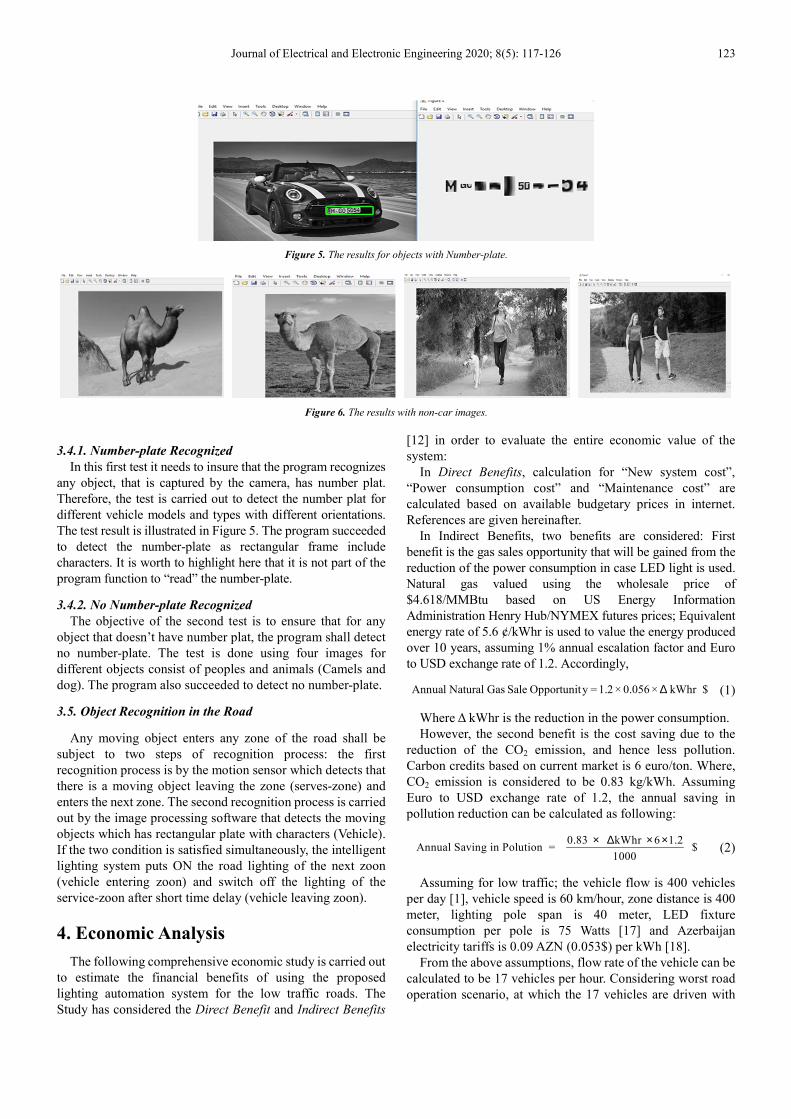
Figure 5. The results for objects with Number-plate.
Figure 6. The results with non-car images.
3.4.1. Number-plate Recognized
In this first test it needs to insure that the program recognizes
any object, that is captured by the camera, has number plat.
Therefore, the test is carried out to detect the number plat for
different vehicle models and types with different orientations.
The test result is illustrated in Figure 5. The program succeeded
to detect the number-plate as rectangular frame include
characters. It is worth to highlight here that it is not part of the
program function to “read” the number-plate.
3.4.2. No Number-plate Recognized
The objective of the second test is to ensure that for any
object that doesn’t have number plat, the program shall detect
no number-plate. The test is done using four images for
different objects consist of peoples and animals (Camels and
dog). The program also succeeded to detect no number-plate.
3.5. Object Recognition in the Road
Any moving object enters any zone of the road shall be
subject to two steps of recognition process: the first
recognition process is by the motion sensor which detects that
there is a moving object leaving the zone (serves-zone) and
enters the next zone. The second recognition process is carried
out by the image processing software that detects the moving
objects which has rectangular plate with characters (Vehicle).
If the two condition is satisfied simultaneously, the intelligent
lighting system puts ON the road lighting of the next zoon
(vehicle entering zoon) and switch off the lighting of the
service-zoon after short time delay (vehicle leaving zoon).
4. Economic Analysis
The following comprehensive economic study is carried out
to estimate the financial benefits of using the proposed
lighting automation system for the low traffic roads. The
Study has considered the Direct Benefit and Indirect Benefits
[12] in order to evaluate the entire economic value of the
system:
In Direct Benefits, calculation for “New system cost”,
“Power consumption cost” and “Maintenance cost” are
calculated based on available budgetary prices in internet.
References are given hereinafter.
In Indirect Benefits, two benefits are considered: First
benefit is the gas sales opportunity that will be gained from the
reduction of the power consumption in case LED light is used.
Natural gas valued using the wholesale price of
$4.618/MMBtu based on US Energy Information
Administration Henry Hub/NYMEX futures prices; Equivalent
energy rate of 5.6 ¢/kWhr is used to value the energy produced
over 10 years, assuming 1% annual escalation factor and Euro
to USD exchange rate of 1.2. Accordingly,
$kWhr × 0.056×1.2 =y Opportunit Sale Gas Natural Annual ∆ (1)
Where ∆ kWhr is the reduction in the power consumption.
However, the second benefit is the cost saving due to the
reduction of the CO2 emission, and hence less pollution.
Carbon credits based on current market is 6 euro/ton. Where,
CO2 emission is considered to be 0.83 kg/kWh. Assuming
Euro to USD exchange rate of 1.2, the annual saving in
pollution reduction can be calculated as following:
0.83 kWhr 6 1.2Annual Saving in Polution = $
1000
× ∆ × × (2)
Assuming for low traffic; the vehicle flow is 400 vehicles
per day [1], vehicle speed is 60 km/hour, zone distance is 400
meter, lighting pole span is 40 meter, LED fixture
consumption per pole is 75 Watts [17] and Azerbaijan
electricity tariffs is 0.09 AZN (0.053$) per kWh [18].
From the above assumptions, flow rate of the vehicle can be
calculated to be 17 vehicles per hour. Considering worst road
operation scenario, at which the 17 vehicles are driven with

124 Muhammad M. A. S. Mahmoud and Leyla Muradkhanli Name: Economical and Safe Design for Low-Traffic Long-Roads Illumination Control System by Using Image Recognition Technique
constant speed of 60 km/hour and equal distances from each
other, it is obvious to conclude that one vehicle shall enter the
first zone each 212 seconds and leaving the zone (400 meter)
after approximately 24 seconds. Accordingly, the zone
lighting fixtures shall be switched on for 29 seconds and
switched of for 183 second approximately. From that, the
percentage saving in power consumption using the proposed
controller compared with the power consumption when road is
illuminated continuously during the night is approximately
183×100 /212= 86% saving.
Considering 4 km low traffic road operating for typically 50
years, Direct benefits and Indirect benefits can be calculated
as following:
4.1. Direct Benefits
4.1.1. Initial Cost of the New Control System
Considering the cost of; camera (approximate number),
day/night sensor, motion sensor, controller (simplest version),
signal transmission between zones by RS-485 network, and
installation (lamp i manpower, crane, dumping etc…), Table 1
can be obtained. The table illustrates that approximately
$ 26,662.88 is needed to provide the proposed automation
lighting system for 4km [12, 19, 20].
4.1.2. Energy Saving
Table 2 illustrates the comparison of energy consumption
between using the proposed automation lighting system
versus conventional system which operates all night,
considering that both systems utilize LED fixtures with
75-Watt as minimum consumption for the conventional
system. The table shows reduction in the power consumption
of 86.31%. This reduces drastically the electrical fault
probability in the lighting electrical circuits [21, 22].
4.1.3. Saving in Maintenance Cost
Table 3 indicates the maintenance cost saving (in terms of
light fixture) such as lamp, manpower, crane, etc. for 50 years’
operation of the proposed automation lighting system and the
conventional system [12].
Table 1. Initial investment.
S. No Definition (in 4 km) With controller Without Controller
1 Total Quantity of LED 100 100
2 Quantity of Day/Night sensor, Motion sensor, Camera & Controller 10 0
3 Unit price for Day/Night sensor, Motion sensor, Camera & Controller including maintenance $107.40 $0
4 Total cost for item 3 $1,074.00 $0
5 Signal transmission between zones $14,698.88 $0
6 Total Cost of Installation $ 10,890.00 $0
a Initial Investment $26,662.88 $0
Table 2. Energy saving.
S. No Description With Controller Without Controller
1 Wattage per fixture (Watt) 75 75
2 № fixtures in 4km 100 100
3 Total power Consumed (Watt) 7500 7500
4 Operating hours (hour) per day 1.643 12
5 Daily operating cycle % 6.8458% 50%
6 Operating hours (hour) in 50 Years 29990.83 219000
7 Power consumed per day (kWh) 12.325 90
8 Power consumed for 50 years (kWh) 224931.25 1642500
9 Total Cost for per day ($) 0.65 4.77
10 Total Cost in 50 years ($) 11,921.36 87,052.50
b Saving in 50 years $75,131.14
Table 3. Saving in maintenance cost.
S. No Description With Controller Without Controller
1 Rated Life (Hours) 100000 100000
2 Operating hours in 50 years 29990.83 219243.33
3 Rate of maintenance in 50 years 0 2
4 Maintenance Cost per lightening pole 108.9 108.9
5 Total Maintenance $ $0.00 21,780.00
c Saving in Maintenance in 50 years $21,780.00
Table 4. Natural gas sales opportunity.
S. No Description With Controller Without Controller
1 Annual Power consumption (kWh) 4498.63 32850
2 Reduction in Power Consumption (kWh) 28351.38
3 Annual Natural Gas Sale Opportunity $1,587.68
d Natural Gas Sale Opportunity in 50 years $79,383.85

Journal of Electrical and Electronic Engineering 2020; 8(5): 117-126 125
Table 5. Saving in Pollution.
S. No Description With Controller Without Controller
1 Annual Power Consumption (kWh) 4498.625 32850
2 Power Consumption in 50 years (kWh) 224931.25 1642500
3 Annual Saving in Pollution $1,694.2752
e Saving in Pollution in 50 years $84,713.76
Table 6. Net Saving analysis in 50 years.
a Initial Investment $ 26,770.28
b Saving in Energy $ 75,131.14
c Saving in Maintenance $ 21,780.00
d Saving in Natural Gas $ 79,383.85
e Saving in Pollution $ 84,713.76
F Total Saving Cost $234,238.47
f Total Saving in 50 years $ 234,238.47
4.2. Indirect Benefits
In indirect saving, two benefits of implementing the
lighting system will be drawn into attention [12].
4.2.1. Natural Gas Sales Opportunity
First benefit is natural gas sales opportunity (Table 4)
gained from reduction of the power consumption calculated
based on below formula (1).
4.2.2. Saving in Pollution
Second benefit is the cost saving due to reduction of the
CO2 emission, hence less pollution. (Table 5) calculate the
related saving based on formula (2).
4.2.3. Total Saving Analysis
Table 6 summaries the calculations in direct and indirect
savings. It is obvious that total saving for only 4 km road in 50
years is $ 234,238.47.
4.3. Discussion
To sum up, huge amount of money can be saved if such
project is implemented. In case that this system is applied to
only 100 km road. Total annual saving becomes about
$117,119.24; total saving in 50 years becomes $5,855,961.75.
It means that such system saves huge amount of energy and
hence expenditure that can be utilized in other projects'
finance. From is discussion, it is also possible to calculates
the “Saving Norm” for the proposed system to be
$1,171.19/km/Year.
5. Conclusion
The paper provided automation design for the illumination
system for low traffic roads in order to solve the problem of
operating the road not only economically but also safely.
Image recognition techniques was used based on
identification of vehicle number-plate to recognize the objects,
is it vehicles or not? Image recognition algorithm was tested
on different objects. The result from test has proved the
validity of the algorithm that is used to detect different types
of vehicle. Comprehensive techno-economic analysis was
carried out and the result showed a great saving can be
achieved, and hence, “Saving Norm” of $1,171.19/km/Year
was calculated for the proposed system too. This “Saving
Norm” is a good index to supports project management for
both project decision makers and for cash-flow controllers.
The calculated value of this “Saving Norm” index encourages
the implementation of this technique in any Low-Traffic
Long-Roads. This index is expected to be much higher, and
hence more cost saving, in case road lighting uses HID bulbs
instead of LED bulbs.
Acknowledgements
I would like to thank Nazrin Dolxanova for her effort in the
survey and collecting information.
References
[1] Cornell University. “What is the traffic volume cut off between high-volume and low volume?” Cornell Local Roads Program. https://www.clrp.cornell.edu/q-a/151-low-volume.html#:~:text=1%2C000%20vehicles%20per%20day%20is,upon%20context%20including%20functional%20classification.
[2] P. V. K. Bhangdiya, “Low Power Consumption of LED Street Light,” International Conference on Global Trends in Signal Processing, Information Computing and Communication, 2016.
[3] Noor Lina Ramli, N. Mohd Yamin, “Implementation of passive infrared sensor in street lighting automation system,” ARPN Journal of Engineering and Applied Sciences, 2015.
[4] Sindhu. A. M, Jerin George, Sumit Roy, Chandra J, “Smart Streetlight Using IR Sensors,” IOSR Journal of Mobile Computing & Application (IOSR-JMCA), 2016.
[5] Ms. M. Kokilavani, Dr. A. Malathi “Smart Street Lighting System using IoT,” International Journal of Advanced Research in Applied Science and Technology ISSN, 2017.
[6] Faiz Ansari, Saima Khan, Aakash Jaiswar, Pooja Khiste, Milind Nemade, “Zigbee Based Smart Street Light Control System,” International Journal of Innovative Research in Science, Engineering and Technology, 2016.
[7] Aman Kumar Akash Oraon Siddharth Agarwal, “Intelligent Street Lighting System Using Gsm,” International Journal of Engineering Science Invention, 2013.

126 Muhammad M. A. S. Mahmoud and Leyla Muradkhanli Name: Economical and Safe Design for Low-Traffic Long-Roads Illumination Control System by Using Image Recognition Technique
[8] D. SA. S. Rajasri, “Automatic streel light control system using wireless sensor networks,” in IEEE international Conference on Power, Control, Signal and Instrumentation Engineering, 2017.
[9] Muhammad M. A. S. Mahmoud, “Typical Economic Model for Calculating the Saving Norm of Replacement HPS Street Lighting by LED Fixtures in Access Road of Gas Production Company at GCC”, 5th International Conference on Electrical and Electronic Engineering (ICEEE), 2018.
[10] Tvilight, “Energy savings through dynamic dimming on the S100 in Nijmegen”, Intelligent Roadway Lighting. https://www.tvilight.com/2016/10/18/case-study-public-roadways/.
[11] Intelilight, “Intelligent Street Lighting,” https://intelilight.eu/.
[12] Muhammad M. A. S. Mahmoud “Economic Model for Calculating the Global Saving Norm of Replacement High-Intensity Discharge Lamps with LED Lamp in Oil and Gas Plant”, IEEE 61st International Scientific Conference on Power and Electrical Engineering of Riga Technical University (RTUCON) 2020.
[13] Reham Faour, Bassel Shanwar, Nizar Zarka, “Recognition of Vehicle Numberplate using MATLAB”, DOI: 10.13140/RG.2.1.1459.8640, 2016.
[14] M. K. B. Ashan and N. G. J. Dias, Recognition of Vehicle License Plates using MATLAB”, European International Journal of Science and Technology Vol. 5 No. 6, August, 2016.
[15] Jing-Ming Guo; Chih-Hsien Hsia; KokSheik Wong and others, Nighttime Vehicle Lamp Detection and Tracking With Adaptive Mask Training”, IEEE Transactions on Vehicular Technology, Vol. 65, Issue: 6, June 2016.
[16] Hazim Hamza Supervisor, Paul WhelanNight, “Time Car Recognition Using MATLAB”, M-Eng in Electronic Systems 2013.
[17] Pacificlamp.com, https://pacificlamp.com/street-light.asp.
[18] Republic, “tariffcouncil.gov.az,”2016. http://www.tariffcouncil.gov.az/?/az/content/70/.
[19] A. A. Circuits, “Low-Cost Programmable Logic Controllers for the Frugal Engineer,” https://www.allaboutcircuits.com/news/low-cost-programmable-logic-controllers-for-the-frugal-engineer/.
[20] Alibaba, “Signal 2cores twisted pair armoured rs485 cable price,” https://www.alibaba.com/product-detail/Signal-2cores-twisted-pair-armoured-rs485_62193928910.html?spm=a2700.7724857.normalList.9.38b06425h3AeQA&s=p.
[21] Muhammad M. A. S. Mahmoud, Detection of single Line-to-Ground Faults Through Impedance in Mesh Distribution Network, IEEE Modern Electrical Power System - MEPS15, Wroclaw 2015.
[22] Muhammad M. A. S. Mahmoud Review of Fuzzy and ANN Fault Location Methods for Distribution Power System in Oil and Gas Sectors, IFAC, Elsevier 2018.
Biography
Muhammad M. A. S. Mahmoud, Egyptian, Received the B.S. degree in Electrical Engineering from Cairo University
and the M.Sc. degree from Kuwait University. First Ph.D. degree from Transilvania University of Brasov, Romania in
IT and Computer. Second PhD Degree in Electrical Power system and Machine, Cairo Univ. Egypt. He occupies a
position of Professor in Process Automation Engineering Department, Baku Higher Oi School, Azerbaijan. His current
research interests in Fuzzy and Artificial Neural Network Techniques application include power delivery, protection
reliability, control, safety, building automation, smart city, and energy management. Prof. Dr. Muhammad is IEEE
Senior Member (SM) since 2001 and TFS –IEEE Reviewer 2016.
Leyla Muradkhanli has received BSc/MSc degrees in Control Systems from Azerbaijan Institute of Oil and Chemistry
and a PhD in Management Information Systems from the Azerbaijan State Oil Academy. She also received an MSc in
Energy Management from BI Norwegian School of Management, Norway. She is Associate Professor in Process
Automation Engineering Department, Baku Higher Oi School, Azerbaijan. Her research interests include Artificial
Intelligence, Machine Learning, Data Science, Energy Management and Alternative Technologies