specification for steel castings, general...
TRANSCRIPT

SPECIFICATION FOR STEEL CASTINGS, GENERALREQUIREMENTS, FOR PRESSURE-CONTAINING
PARTS
SA-703/SA-703M
(Identical with ASTM Specification A 703/A 703M-94.)
1. Scope
1.1 This specification covers a group of commonrequirements which, unless otherwise specified in anindividual specification, shall apply to steel castingsfor pressure-containing parts under each of the followingASTM specifications:
ASTMTitle of Specification Designation
Steel Castings, Carbon, Suitable for Fusion A 216/A 216MWelding for High-Temperature Service
Steel Castings, Martensitic Stainless and A 217/A 217MAlloy, for Pressure-Containing Parts Suit-able for High-Temperature Service
Steel Castings, Austenitic, for High-Temper- A 351/A 351Mature Service
Steel Castings, Ferritic and Martensitic, for A 352/A 352MPressure-Containing Parts Suitable forLow-Temperature Service
Steel Castings, Alloy, Specially Heat- A 389/A 389MTreated, for Pressure-Containing Parts,Suitable for High-Temperature Service
Steel Castings Suitable for Pressure Service A 487/A 487M
1.2 This specification also covers a group of supple-mentary requirements which may be applied to theabove specifications as indicated therein. These areprovided for use when additional testing or inspectionis desired and apply only when specified individuallyby the purchaser in the order.
1.3 In case of conflict between the requirements ofthe individual specification and this general specifica-tion, the former shall prevail.
1.4 The values stated in either inch-pound units orSI units are to be regarded separately as standard.Within the text, the SI units are shown in brackets. The
1202
values stated in each system are not exact equivalents;therefore, each system must be used independently ofthe other. Combining values from the two systems mayresult in nonconformance with the specification. Inch-pound units are applicable for material ordered toSpecification A 703 and SI units for material orderedto Specification A 703M.
2. Referenced Documents
2.1 ASTM Standards:A 216/A 216M Specification for Steel Castings, Carbon,
Suitable for Fusion Welding for High-TemperatureService
A 217/A 217M Specification for Steel Castings, Marten-sitic Stainless and Alloy, for Pressure-Containing PartsSuitable for High-Temperature Service
A 351/A 351M Specification for Castings, Austenitic,Austenitic-Ferritic (Duplex), for Pressure ContainingParts
A 352/A 352M Specification for Steel Castings, Ferriticand Martensitic, for Pressure-Containing Parts Suitablefor Low-Temperature Service
A 370 Test Methods and Definitions for Mechanical Test-ing of Steel Products
A 389/A 389M Specification for Steel Castings, Alloy,Specially Heat-Treated, for Pressure-Containing Parts,Suitable for High-Temperature Service
A 487/A 487M Specification for Steel Castings Suitablefor Pressure Service
A 488/A 488M Practice for Steel Castings, Welding,Qualification of Procedures and Personnel
A 609/A 609M Practice for Castings, Carbon, Low-Alloy,and Martensitic Stainless Steel, Ultrasonic Examina-tion Thereof
COPYRIGHT American Society of Mechanical EngineersLicensed by Information Handling ServicesCOPYRIGHT American Society of Mechanical EngineersLicensed by Information Handling Services
PART A — FERROUS MATERIAL SPECIFICATIONS SA-703/SA-703M
A 751 Test Methods, Practices, and Terminology forChemical Analysis of Steel Products
A 800/A 800M Practice for Steel Casting, AusteniticAlloy, Estimating Ferrite Content Thereof
A 802/A 802M Practice for Steel Castings, Surface Ac-ceptance Standards, Visual Examination
A 919 Terminology Relating to Heat Treatment of MetalsE 29 Practice for Using Significant Digits in Test Data
to Determine Conformance with SpecificationsE 94 Guide for Radiographic TestingE 125 Reference Photographs for Magnetic Particle Indi-
cations on Ferrous CastingsE 165 Practice for Liquid Penetrant Inspection MethodE 186 Reference Radiographs for Heavy-Walled (2 to 4
1⁄2 in. [51 to 114-mm] Steel CastingsE 208 Test Method for Conducting Drop-Weight Test
to Determine Nil-Ductility Transition Temperature ofFerritic Steels
E 280 Reference Radiographs for Heavy-Walled (4-1⁄2 to12 in. [114 to 305-mm]) Steel Castings
E 340 Method for Macroetching Metals and AlloysE 446 Reference Radiographs for Steel Castings up to 2
in. (51 mm) in ThicknessE 709 Practice for Magnetic Particle Examination
2.2 ANSI Standard:B16.5 Steel Pipe Flanges and Flanged Fittings
2.3 ASME:ASME Boiler and Pressure Vessel Code, Section III,
NB-2546
2.4 Standards of the Manufacturer’s StandardizationSociety of the Valve and Fitting Industry:MSS SP 53 Quality Standard for Steel Castings for
Valves, Flanges and Fittings, and Other Piping Compo-nents (Dry Powder Magnetic Particle InspectionMethod)
MSS SP 54 Quality Standard for Steel Castings forValves, Flanges and Fittings, and Other Piping Compo-nents (Radiographic Inspection Method)
3. Terminology
3.1 Definitions:
3.1.1 The definitions in Test Methods and Defini-tions A 370 and Terminology A 919 are applicable tothis specification and those listed in 1.1.
3.1.2 chaplet, n—a chaplet is a metallic supportplaced in a mold cavity to maintain the spacing betweena core and the mold.
1203
3.1.3 heat, n—all the molten metal poured froma single furnace or all the molten metal from two ormore furnaces poured into single ladle or casting priorto the replenishing of the furnace(s).
3.1.4internal chill, n—an internal chill is a metallicdevice placed in a mold cavity to increase the rate ofheat removal at that location.
4. Materials and Manufacture
4.1 Melting Process—The steel shall be made byopen-hearth or electric-furnace process, with or withoutseparate refining such as argon-oxygen-decarburization(AOD), unless otherwise designated by the individualspecification.
4.2 Heat Treatment—Ferritic and martensitic steelshall be cooled after pouring to provide substantiallycomplete transformation of austenite prior to heat treat-ment to enhance mechanical properties.
5. Chemical Composition
5.1 Chemical Analysis—Chemical analysis of materi-als covered by this specification shall be in accordancewith Test Methods A 751.
5.2 Heat Analysis—An analysis of each heat shallbe made by the manufacturer to determine the percent-ages of the elements specified. The analysis shall bemade from a test sample preferably taken during thepouring of the heat. When drillings are used, they shallbe taken not less than1⁄4 in. [6.4 mm] beneath thesurface. The chemical composition thus determinedshall be reported to the purchaser, or his representative,and shall conform to the requirements in the individualspecification for the grade being poured.
5.3 Product Analysis—A product analysis may bemade by the purchaser from material representing eachheat, lot, or casting. The analysis shall be made onrepresentative material. Due to the possibility of decarb-urization, carbon and alloy steel samples for carbonanalysis shall be taken no closer than1⁄4 in. [6.4 mm]to a cast surface except that castings too thin forthis shall be analyzed on representative material. Thechemical composition thus determined shall meet therequirements specified in the appllicable specificationfor the grade involved, or shall be subject to rejectionthe purchaser, except that the chemical compositiondetermined for carbon and low-alloy steel castings mayvary from the specified limits by the amounts shownin Table 1. The product analysis tolerances of Table
COPYRIGHT American Society of Mechanical EngineersLicensed by Information Handling ServicesCOPYRIGHT American Society of Mechanical EngineersLicensed by Information Handling Services

SA-703/SA-703M 2001 SECTION II
1 are not applicable as acceptance criteria for heatanalysis by the casting manufacturer.
5.4 Unspecified Elements—When chemical analysisfor elements not specified for the grade ordered isdesired, Supplementary Requirement S1 may be spec-ified.
5.5 The substitution of a grade or composition differ-ent from that specified by the purchaser is prohibited.
6. Mechanical Test Methods
6.1 All mechanical tests shall be conducted in accord-ance with Test Methods and Definitions A 370.
7. Tensile Requirements
7.1 One tension test shall be made from each heat,and shall conform to the tensile requirements specified.Test bars shall be poured in special blocks from thesame heat as the castings represented, except that forinvestment castings the test specimens shall be cast inthe same type of mold as the castings.
7.2 The bar from which the test specimen is takenshall be heat treated in production furnaces to the sameprocedure as the castings it represents.
7.3 Test specimens may be cut from heat treatedcastings, at the producer’s option, instead of fromtest bars.
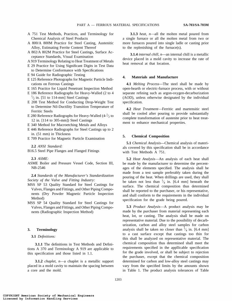
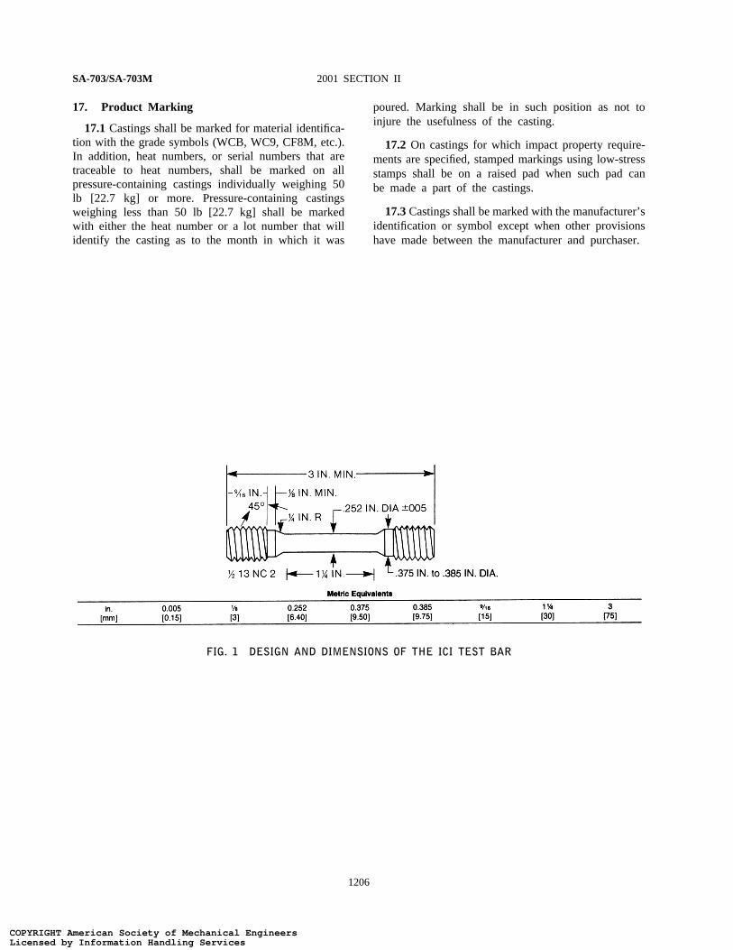
7.4 Investment Castings—For investment castings,the specimens may be cast to shape or machined fromblocks to dimensions in accordance with Test Methodsand Definitions A 370 or the ICI bar shown in Fig. 1.
7.5 Other Castings—Unless otherwise specified bythe purchaser, test coupons may be cast integrally withthe castings or as separate blocks in accordance withFig. 1 and Table 2, with Fig. 2, or with Fig. 3, exceptwhen Supplementary Requirement S26 is specified. Thetest coupon in Fig. 4 shall be employed only foraustenitic alloy castings with cross sections less than21⁄2 in. [63.5 mm]. Tension test coupons shall bemachined or ground to the form and dimension shownin Fig. 6 of Test Methods and Definitions A 370.
7.6 If any specimen shows defective machining ordevelops flaws, it may be discarded and another substi-tuted from the same heat.
7.7 To determine conformance with the tension testrequirements, an observed value or calculated valueshall be rounded off in accordance with Practice E 29
1204
to the nearest 500 psi [5 MPa] for yield and tensilestrength and to the nearest 1% for elongation andreduction of area.
8. Repair by Welding
8.1 Repair by welding shall be in accordance withthe requirements of individual specification using proce-dures and welders qualified in accordance with PracticeA 488/A 488M.
9. Flanges
9.1 When a flange from a flanged casting is removedto make a weld end casting, discontinuities may beobserved that would not have been detrimental in aflanged casting. The disposition of the casting shallbe subject to agreement between the purchaser andmanufacturer.
10. Quality
10.1 The surface of the casting shall be free ofadhering sand, scale, cracks, and hot tears as determinedby visual examination. Other surface discontinuitiesshall meet the visual acceptance standards specified inthe order. Practice A 802/A 802M or other visualstandards may be used to define acceptable surfacediscontinuities and finish. Unacceptable visual surfacediscontinuities shall be removed and their removalverified by visual examination of the resultant cavities.
10.2 The castings shall not be peened, plugged, orimpregnated to stop leaks.
10.3 Internal chills and chaplets may be used in themanufacture of castings. However, the chills, chaplets,and affected cast material must be completely removed.
11. Hydrostatic Tests
11.1 Each casting shall be tested after machining tothe hydrostatic shell test pressures prescribed in ANSIB16.5 for the applicable steel rating for which thecasting is designed. Casting shall show no leaks. Cast-ings ordered for working pressures other than those inthe standard ANSI ratings, or those listed for whichtest pressures are not specified by ANSI B16.5, shallbe tested at a pressure agreed upon between manufac-turer and the purchaser.
COPYRIGHT American Society of Mechanical EngineersLicensed by Information Handling ServicesCOPYRIGHT American Society of Mechanical EngineersLicensed by Information Handling Services

PART A — FERROUS MATERIAL SPECIFICATIONS SA-703/SA-703M
11.2 It is realized that the foundry may be unableto perform the hydrostatic test prior to shipment, orthat the purchaser may wish to defer testing untiladditional work or machining has been performed onthe casting. Castings ordered in the rough state forfinal machining by the purchaser may be tested hydro-statically prior to shipment by the manufacturer atpressures to be agreed upon with the purchaser. How-ever, the foundry is responsible for the satisfactoryperformance of the castings under the final test requiredin 10.1.
12. Workmanship, Finish, and Appearance
12.1 All castings shall be made in a workmanlikemanner and shall conform to the dimensions on drawingsfurnished by the purchaser. When the patterns is sup-plied by the purchaser, the dimensions of the castingsshall be as predictated by the pattern unless otherwiseagreed upon.
12.2 Machined welding ends shall be suitably pro-tected against damage during shipping.
13. Retests
13.1 If the results of the mechanical tests for anyheat, lot, or casting do not conform to the requirementsspecified, retests are permitted as outlined in TestMethods and Definitions A 370. At the manufacturer’soption, castings may be reheat-treated and retested.When castings are reheat-treated, they may not bereaustenitized more than three times without the ap-proval of the purchaser. Testing after reheat treatmentshall consist of the full number of specimens takenfrom locations complying with the specification or order.
14. Inspection
14.1 The manufacturer shall afford the purchaser’sinspector all reasonable facilities necessary to satisfythat the material is being produced and furnished inaccordance with the applicable specification. Foundryinspection by the purchaser shall not interfere unneces-sarily with the manufacturer’s operations. All tests andinspections, with the exception of product analysis (5.2),shall be made at the place of manufacture unlessotherwise agreed.
1205
15. Rejection and Rehearing
15.1 Any rejection based on test reports shall bereported to the manufacturer within 30 days from thereceipt of the test reports by the purchaser.
15.2Material that shows unacceptable discontinuitiesas determined by the acceptance standards specified inthe order subsequent to its acceptance at the manufactur-er’s works will be rejected, and the manufacturer shall benotified within 30 days after discovery of the rejectablecondition.
15.3 Samples that represent rejected material shallbe preserved for two weeks from the date of transmissionof the test report. In case of dissatisfaction with theresults of the tests, the manufacturer may make claimfor a rehearing within that time.
16. Certification
16.1 The manufacturer’s certification shall be fur-nished to the purchaser stating that the material wasmanufactured, sampled, tested, and inspected in accord-ance with the material specification (including year ofissue) and was found to meet the requirements.
16.2As applicable, the certification shall also include:
16.2.1 Material specification and grade.
16.2.2 Pattern number.
16.2.3 Heat number or serial number traceable toa heat number.
16.2.4 Chemical analysis of the heat.
16.2.5Mechanical property results required by thespecification and supplementary requirements specifiedin the purchase order.
16.2.6Statement of satisfactory inspection, visual,and nondestructive testing specified in the purchaseorder.
16.2.7 Manufacturer’s name.
16.2.8 Additional purchase order requirements.
16.3 A signature is not required on the certification.However, the document shall clearly identify the organi-zation submitting the certification. Notwithstanding theabsence of a signature, the organization submitting thecertification is responsible for its content.
COPYRIGHT American Society of Mechanical EngineersLicensed by Information Handling ServicesCOPYRIGHT American Society of Mechanical EngineersLicensed by Information Handling Services
SA-703/SA-703M 2001 SECTION II
17. Product Marking
17.1Castings shall be marked for material identifica-tion with the grade symbols (WCB, WC9, CF8M, etc.).In addition, heat numbers, or serial numbers that aretraceable to heat numbers, shall be marked on allpressure-containing castings individually weighing 50lb [22.7 kg] or more. Pressure-containing castingsweighing less than 50 lb [22.7 kg] shall be markedwith either the heat number or a lot number that willidentify the casting as to the month in which it was
FIG. 1 DESIGN AND DIMENSIONS OF THE ICI TEST BAR
1206
poured. Marking shall be in such position as not toinjure the usefulness of the casting.
17.2 On castings for which impact property require-ments are specified, stamped markings using low-stressstamps shall be on a raised pad when such pad canbe made a part of the castings.
17.3Castings shall be marked with the manufacturer’sidentification or symbol except when other provisionshave made between the manufacturer and purchaser.
COPYRIGHT American Society of Mechanical EngineersLicensed by Information Handling ServicesCOPYRIGHT American Society of Mechanical EngineersLicensed by Information Handling Services
PART A — FERROUS MATERIAL SPECIFICATIONS SA-703/SA-703M
FIG. 2 TEST COUPONS FOR CASTINGS (SEE TABLE 2 FOR DETAILS OF DESIGN)
FIG. 3 TEST BLOCK FOR TENSION TEST SPECIMEN
1207
COPYRIGHT American Society of Mechanical EngineersLicensed by Information Handling ServicesCOPYRIGHT American Society of Mechanical EngineersLicensed by Information Handling Services

SA-703/SA-703M 2001 SECTION II
FIG. 4 CAST-TO-SHAPE TEST COUPON FOR TENSION TEST SPECIMEN
1208
COPYRIGHT American Society of Mechanical EngineersLicensed by Information Handling ServicesCOPYRIGHT American Society of Mechanical EngineersLicensed by Information Handling Services

PART A — FERROUS MATERIAL SPECIFICATIONS SA-703/SA-703M
TABLE 1PRODUCT ANALYSIS TOLERANCES FOR CARBON
AND LOW-ALLOY STEELS
TolerancesB,C over maxElement RangeA or under min, Limit, %
Carbon (C) up to 0.65% 0.03 × % CL + 0.02above 0.65% 0.04%
Manganese (Mn) up to 1% 0.08 × % MnL + 0.01above 1% 0.09
Silicon (Si) up to 0.60% 0.22 × % SiL − 0.01above 0.60% 0.15%
Phosphorus (P) all 0.13 × % PL + 0.005Sulfur (S) all 0.36 × % SL + 0.001Nickel (Ni) up to 2% 0.10 × % NiL + 0.03
above 2% 0.25%Chromium (Cr) up to 2% 0.07 × % CrL + 0.04
above 2% 0.18%Molybdenum (Mo) up to 0.6% 0.04 × % MoL + 0.03
above 0.6% 0.06%Vanadium (V) up to 0.25% 0.23 × % VL + 0.004
above 0.25% 0.06%Tungsten (W) up to 0.10% 0.08 × % WL + 0.02
above 0.10% 0.02%Copper (Cu) up to 0.15% 0.18 × % CuL + 0.02
above 0.15% 0.05%Aluminum (Al) up to 0.10% 0.08 × % AlL + 0.02
above 0.10% 0.03%
A The range denotes the composition limits up to which the toler-ances are computed by the equation, and above which the tolerancesare given by a constant.
B The subscript L for the elements in each equation indicates thatthe limits of the element specified by the applicable specification areto be inserted into the equation to calculate the tolerance for theupper limit and the lower limit, if applicable, respectively. Examplesof computing tolerances are presented in the footnote C.
C To compute the tolerances, consider the manganese limits 0.50− 80% of Grade WC4 of Specification A 217/A 217M. Accordingto Table 1, the maximum permissible deviation of a product analysisbelow the lower limit 0.50 is 0.05% p (0.08 × 0.50 + 0.01).The lowest acceptable product analysis of Grade WC4, therefore, is0.45%. Similarly, the maximum permissible deviation above the upperlimit of 0.80% is 0.074% p (0.08 × 0.80 + 0.01). The highestacceptable product analysis of Grade WC4, therefore, is 0.874. ForGrade WCC of Specification A 216/A 216M, the maximum manganesecontent is 1.20% if the carbon content is 0.20%. In this case, thehighest acceptable product analysis is 1.29 p (1.20 + 0.09).
1209
COPYRIGHT American Society of Mechanical EngineersLicensed by Information Handling ServicesCOPYRIGHT American Society of Mechanical EngineersLicensed by Information Handling Services

SA-703/SA-703M 2001 SECTION II
TABLE 2DETAILS OF TEST COUPON DESIGN FOR CASTING (SEE FIG. 2)
NOTE 1 — Test Coupons for Large and Heavy Steel Castings: The test coupons in Fig. 2 are to be used for large and heavy steel castings.However, at the option of the foundry the cross-sectional area and length of the standard coupon may be increased as desired.
NOTE 2 — Bend Bar: If a bend bar is required, an alternate design (as shown by dotted lines in Fig. 2) is indicated.
Leg Design [125 mm] Riser Design
1. L (length) A 5 in. [125 mm] minimum length will be 1. L (length) The length of the riser at the base will beused. This length may be increased at the same as the top length of the leg.the option of the foundry to accommo- The length of the riser at the top there-date additional test bars (see Note 1). fore depends on the amount of taper
added to the riser.2. End taper Use of and size of end taper is at the op- 2. Width The width of the riser at the base of a
tion of the foundry. multiple-leg coupon shall be n, 21⁄4 [573. Height 11⁄4 in. [32 mm] mm] — 5⁄8 [16 mm] where n equals the4. Width (at top) 11⁄4 in. [32 mm] (see Note 1). number of legs attached to the coupon.5. Radius (at bottom) 1⁄2 in. [13 mm], max The width of the riser at the top is6. Spacing between legs A 1⁄2 in. [13 mm] radius will be used be- therefore dependent on the amount of
tween the legs. taper added to the riser.7. Location of test bars The tensile, bend, and impact bars will be 3. T (riser taper) Use of and size is at the option of the
taken from the lower portion of the leg foundry.(see Note 2).
8. Number of legs The number of legs attached to the cou- Heightpon is at the option of the foundry pro-viding they are equispaced according toitem 6.
9. Rs Radius from 0 to approximately 1⁄16 in. [2mm].
The minimum height of the riser shall be2 in. [51 mm]. The maximum height isat the option of the foundry for the fol-lowing reasons: (a) Many risers arecast open, (b) different compositionsmay require variation in risering forsoundness, (c) different pouring temper-atures may require variation in riseringfor soundness.
1210
COPYRIGHT American Society of Mechanical EngineersLicensed by Information Handling ServicesCOPYRIGHT American Society of Mechanical EngineersLicensed by Information Handling Services

PART A — FERROUS MATERIAL SPECIFICATIONS SA-703/SA-703M
SUPPLEMENTARY REQUIREMENTS
The following standardized supplementary requirements are for use when desiredby the purchaser and when allowed by and listed in the individual specifications.They shall not apply unless specified in the order, in which event the specified testsshall be made by the manufacturer before shipment of the castings.
S1. Unspecified Elements
S1.1 Limits may be established for elements notspecified for the grade ordered by agreement betweenthe manufacturer and purchaser. The results of theanalysis for the agreed-upon elements shall be reported.
S2. Destruction Tests
S2.1 Purchaser may select representative castingsfrom each heat and cut up and etch, or otherwiseprepare, the sections for examination for internal defects.Should injurious defects be found that evidence unsoundsteel or faulty foundry technique, all the castings madefrom that particular pattern, heat, and heat treatmentcharge may be rejected. All the rejected castings includ-ing those cut up, shall be replaced by the manufacturerwithout charge.
S3. Bend Test
S3.1One bend test shall be made from a test couponfrom each heat in accordance with Test Methods andDefinitions A 370, and shall be machined to 1 by1⁄2in. [25 by 13 mm] section with corners rounded to aradius not over1⁄16 in. [1.6 mm].
S3.2The specimen shall withstand being bent longitu-dinally at room temperature through an angle of 90°about a pin the diameter of which shall be the specimenthickness for carbon steel, and 1 in. [25 mm] for othersteels. The specimen shall show no cracks on theoutside of the bent portion of the specimen.
S3.3 Bend test specimens may be cut from heat-treatment castings instead of from test bars when agreedupon between manufacturer and purchaser.
S3.4If any test specimen shows defective machiningor develops flaws, it may be discarded and anotherspecimen substituted from the same heat.
1211
S4. Magnetic Particle Inspection
S4.1Castings shall be examined for surface and nearsurface discontinuities by magnetic particle inspection.The examination shall be in accordance with PracticeE 709; and types and degrees of discontinuities consid-ered shall be judged by the Reference Photographs E125. Extent of examination, time of examination, andbasis for acceptance shall be agreed upon between themanufacturer and purchaser. A specification which maybe used as a basis for such agreement is MSS SP 53.
S4.2 Personnel performing the examination shall bequalified in accordance with an acceptable writtenpractice.
S5. Radiographic Inspection
S5.1 Castings shall be examined for internal defectsby means of X rays or gamma rays. The procedureshall be in accordance with Guide E 94 and types anddegrees of discontinuities considered shall be judgedby Reference Radiographs E 446, E 186, or E 280.Extent of examination and basis for acceptance shallbe agreed upon between the manufacturer and purchaser.A specification that may be used as a basis for suchagreement is MSS SP 54.
S5.2 Radiographic examination of castings may beperformed before or after any heat treatment.
S5.3 Personnel performing the examination shall bequalified in accordance with an acceptable writtenpractice.
S6. Liquid Penetrant Inspection
S6.1Castings shall be examined for surface disconti-nuities by means of liquid penetrant inspection. Theexamination shall be in accordance with Practice E165. Areas to be inspected, time of inspection, methodsand types of liquid penetrants to be used, developingprocedure, and basis for acceptance shall be agreedupon between the manufacturer and purchaser. In the
COPYRIGHT American Society of Mechanical EngineersLicensed by Information Handling ServicesCOPYRIGHT American Society of Mechanical EngineersLicensed by Information Handling Services

SA-703/SA-703M 2001 SECTION II
absence of available reference standards for liquidpenetrant inspection, indications may be compared withReference Photographs E 125 or referenced to ASMESection III, NB-2546.
S6.2 Personnel performing the examination shall bequalified in accordance with an acceptable writtenpractice.
S7. Ultrasonic Inspection
S7.1 Castings shall be examined for internal defectsby means of ultrasonic inspection. The inspection proce-dure shall be in accordance with Practice A 609/A609M. Extent of examination, methods of test, andbasis for acceptance shall be agreed upon between themanufacturer and purchaser.
S7.2 Ultrasonic examination of castings shall beperformed after at least one heat treatment above thecritical temperature range but need not be repeatedafter subsequent heat treatment.
S7.3 Personnel performing the examination shall bequalified in accordance with an acceptable writtenpractice.
S8. Charpy Impact Test
S8.1Charpy impact test properties shall be determinedon each heat from a set of three charpy V-notchspecimens made from a test coupon in accordance withTest Methods and Definitions A 370, and tested at atest temperature agreed upon by the manufacturer andpurchaser. The acceptance requirements shall be eitherenergy absorbed, lateral expansion, or percent sheararea, or all three, and shall be that agreed upon bythe manufacturer and purchaser. Test specimens shallbe prepared as Type A and tested in accordance withTest Methods and Definitions A 370.
S8.2 Absorbed Energy—Average energy value ofthree specimens shall be not less than specified, withnot more than one value permitted to fall below theminimum specified and no value permitted below theminimum specified for a single specimen.
S8.3 Lateral Expansion—Lateral expansion valueshall be agreed upon by the manufacturer and purchaser.
S8.4 Percent Shear Area—Percent shear area shallbe agreed upon by the manufacturer and purchaser.
1212
S9. Drop Weight Tests
S9.1Drop weight test properties shall be determinedfrom each heat by preparing and testing either TypeP1, P2, or P3 specimens in accordance with TestMethod E 208. The crack starter weld shall be depositedon the surface of the specimen that was nearest to thecasting surface. Each test shall consist of at least twospecimens tested at a temperature agreed upon by themanufacturer and purchaser. Each specimen shall exhibit“no break” performance.
S10. Examination of Weld Preparation
S10.1Magnetic particle or liquid penetrant examina-tion of cavities prepared for welding shall be performedto verify removal of those discontinuities found unac-ceptable by the inspection method specified for thecasting. The method of performing magnetic particleor liquid penetrant examination shall be in accordancewith Practice E 709 or Practice E 165. Unless otherdegrees of shrinkage or types of discontinuities foundin the cavities are specified, Type II, Internal Shrinkage,of Reference Photographs E 125, of Degree 2 in sectionsup to 2 in. [50 mm] thick and of Degree 3 in sectionsover 2 in. [50 mm] thick shall be acceptable.
S12. Prior Approval of Major Weld Repairs
S12.1 Major weld repairs shall be subject to theprior approval of the purchaser.
S13. Hardness Test
S13.1 A hardness test shall be made in accordancewith Test Methods and Definitions A 370. The testlocation and the hardness requirements shall be agreedupon between the manufacturer and the purchaser.
S14. Tension Test from Each Heat and HeatTreatment Charge
S14.1One tension test shall be made for each heatand heat treatment charge.
S15. Quench and Temper Heat Treatment
S15.1The castings shall be quenched and tempered.Castings so treated shall be marked QT.
COPYRIGHT American Society of Mechanical EngineersLicensed by Information Handling ServicesCOPYRIGHT American Society of Mechanical EngineersLicensed by Information Handling Services

PART A — FERROUS MATERIAL SPECIFICATIONS SA-703/SA-703M
S17. Tension Test from Castings
S17.1 In addition to the tensile test required inSection 6, test material shall be cut from heat treatedcastings. The mechanical properties and location forthe test material shall be agreed upon by the manufac-turer and purchaser.
S18. Tension Test for Castings Each Weighing10 000 lb [4500 kg] or More
S18.1Two tensile tests shall be made for each casting.The test specimens shall be prepared in accordance withSection 6. The location of the test bars shall be agreedupon by the manufacturer and purchaser.
S20. Weld Repair Charts
S20.1 Major weld repairs shall be documented bymeans of sketches or photographs or both showing thelocation and major dimensions of cavities preparedfor welding. Documentation shall be submitted to thepurchaser at the completion of the order.
S20.2A weld repair shall be considered major whenit is made to correct leakage on hydrostatic testing, orwhen the depth of the cavity prepared for weldingexceeds 20% of the actual wall thickness or 1 in. [25mm], whichever is smaller, or when the extent of thecavity exceeds approximately 10 in.2 [65 cm2].
S21. Heat Treatment Furnace Record
S21.1 A heat treatment chart showing time andtemperature shall be prepared and be available forinspection by the purchaser.
S22. Heat Treatment
S22.1 Test specimens shall be heat-treated togetherwith the castings they represent. Heat-treated specimensshall be tested and shall meet the tensile and impactproperties specified.
S22.2The remaining test specimens from Supplemen-tary Requirement S22.1 representing the casting shallbe treated thermally after the final (foundry) heat-treatment to simulate heat-treatments below the criticaltemperature which the casting may receive during fabri-cation, and then tested for mechanical properties. Time,temperature and cooling rate shall be as stated in theorder. In the case of postweld heat-treatment, the total
1213
time at temperature or temperatures for the test materialshall be at least 80% of the total time at temperatureor temperatures during actual postweld heat-treatmentof the fabrication of which the casting or castings area part. The total time at temperature or temperaturesfor the test material may be performed in a single cycle.When this Supplementary Requirement is specified, thewelding qualification test metal must be processed inthe same manner.
S23. Macroetch Test
S23.1Apply Supplementary Requirement S1 for thespectrographic determination and reporting of the totalresidual aluminum content of all heats of ferritic andmartensitic steels subjected to this macroetch test.
S23.2When the heat analysis indicates a total residualaluminum content in excess of 0.08%, the manufacturershall etch a cross section of the casting with the heaviestsection for which this supplementary requirement isinvoked, or a coupon attached to that heaviest sectionor an area directly under a riser (Note S23.1). Crosssections, from a separately cast test block from thesame heat and of a thickness representative of theheaviest section of castings purchased under this supple-mentary requirement, may also be used for macroetchtesting. The etching shall be performed on the selectedsection after its heat-treatment, that is, after annealing,normalizing, or quenching and tempering following theinitial cooling of the steel below the transformationrange.
NOTE S23.1—High strength martensitic castings, in particular, maybe damaged beyond use if the etch is applied directly to the casting.
S23.3The preparation of the surface and the macro-etching procedure with solution No. 1 (1:1 HCl) ofTable 5 in Test Method E 340 shall be followed. Theresulting etched surface shall be compared and ratedwith the reference photographs in Fig. S23.1 depicting10 levels of severity of intergranular network structuresindicative of the presence of aluminum nitride, orother constituents prone toward precipitating at grainboundaries during solidification and subsequent cooling.Table S23.1 relates the severity levels shown in thesephotographs with specific delineation widths and percentof boundary outlining in the etched structures.
S23.4Castings represented by etched structures exhib-iting a network rating in excess of Severity Level 4 shallbe considered unacceptable until further evaluations arecompleted. The acceptability of individual castings maybe determined by etching sections of each casting to
COPYRIGHT American Society of Mechanical EngineersLicensed by Information Handling ServicesCOPYRIGHT American Society of Mechanical EngineersLicensed by Information Handling Services

SA-703/SA-703M 2001 SECTION II
ascertain the network severity level. Disposition ofunacceptable castings shall be a matter of agreementbetween the manufacturer and purchaser. Those castingsexhibiting etched severity levels greater than four maybe further evaluated by any of the following agreedupon methods:
S23.4.1Fracture testing to determine the amountof “rock candy” structure.
S23.4.2Mechanical testing (bend, tensile, etc.) todetermine the ductility characteristics.
S23.4.3Weld testing to determine crack suscepti-bility in the heat-affected zone of a circular groovewelded with cellulose coated electrodes.
S23.5 Alternatively, by agreement, it is permissibleto subject castings from an unacceptable heat to ahigh temperature solution treatment prior to the normalproduction heat-treatment and subsequently macroetchtest each casting.
S23.6 Heavy section castings (Note S23.2) whoseconfigurations are amenable to the attachment of testcoupons representative of the section thickness involvedand from which standard 0.505 in. [12.827 mm] diame-ter tension specimens may be machined are exemptfrom this macroetch test if the results of the tensiontest on the coupon after heat-treatment of the castingmeet the minimum requirements specified for the gradeof steel involved.
NOTE S23.2—For purposes of this supplementary requirement, aheavy section casting is defined as one having a wall thickness of11⁄2 in. (37 mm) or greater in combination with a casting weightof at least 1000 lb (455kg).
S24. Specified Ferrite Content Range
S24.1 The chemical composition of the heat shallbe controlled such that the ferrite content, as determinedby the chemical composition procedure of Practice A800/A 800M, shall be in conformance with the specifiedferrite content range.
S24.2The specified ferrite content range shall be asagreed upon between the manufacturer and the pur-chaser. The minimum specified ferrite content rangeshall be 10% with the minimum ferrite content beingno lower than the percent necessary to achieve theminimum mechanical properties required for the alloy.
S24.3Should the purchaser wish to have the ferritecontent determined by either magnetic response ormetallographic methods, the purchaser should impose
1214
supplementary requirement S1 or S2 of Practice A 800/A 800M.
S25. Heat Treatment Certification
S25.1 Heat treatment temperature and cycle timesshall be shown on the certification report.
S26. Alternate Tension Test Coupons andSpecimen Locations for Castings (in-lieu ofTest Bars Poured from Special Blocks)
S26.1 Test blocks may be cast integrally with thecastings or as separate blocks. Test blocks shall beheat-treated together with the castings they represent.
S26.2 The casting thickness,T, is the maximumthickness of the pressure containing wall of the castingexclusive of padding added for directional solidification,flanges, appendages, and sections designated by thedesigner as noncritical. The order, inquiry, and drawingshall designate what the test dimension,T, is for thecasting.
S26.3 One of the following shall apply:
S26.3.1 The longitudinal centerline of the testspecimen shall be taken at least1⁄4 T from the Tdimension surface and all of the gage length must beat least 1T from any other heat-treated surface, exclusiveof the surface opposite theT dimension surface. (SeeFig. S26.1(a).) For cylindrical castings, the longitudinalcenterline of the specimens shall be taken at least1⁄4T from the outside or inside and all of the gage lengthmust be at leastT from the as-heat-treated end. (SeeFig. S26.1(b).)
S26.3.2For ferritic and martensitic castings, partialsevering of test blocks prior to final heat treatment ispermitted.
S26.3.3 Where separately cast test coupons areused, the dimension shall shall not be less than 3T by3T by T and each specimen shall meet the requirementsof S26.3.1, except that whenT exceeds 5 in. (125mm), the dimension may be 15 by 15 by 5 in. (375by 375 by 125 mm), by agreement between the manufac-turer and the purchaser. The test coupon shall be ofthe same heat of steel and shall receive substantiallythe same casting practices as the production casting itrepresents. Centrifugal castings may be represented bystatically cast coupons. (See Fig. S26.2.)
S26.3.4When agreed upon between the manufac-turer and the purchaser, castings that are cast or ma-
COPYRIGHT American Society of Mechanical EngineersLicensed by Information Handling ServicesCOPYRIGHT American Society of Mechanical EngineersLicensed by Information Handling Services

PART A — FERROUS MATERIAL SPECIFICATIONS SA-703/SA-703M
chined to essentially the finished configuration prior toheat-treatment shall have test specimens removed froma prolongation or other stock on the casting at a locationbelow the nearest heat-treated surface indicated on theorder. The specimen location shall be at a distancebelow the nearest heat-treated surface equivalent to atleast the greatest distance that the indicated high-tensile-stress surface will be from the nearest heat-treatedsurface and a minimum of twice this distance from asecond heat-treated surface, except that the test speci-mens shall be no nearer than3⁄4 in. (19 mm) to aheat-treated surface and 11⁄2 in. (38 mm) from a secondheat-treated surface. (See Fig. S26.3.)
S26.3.5Where specimens are to be removed fromthe body of quenched and tempered castings, either
FIG. S23.1 REFERENCE PHOTOGRAPHS OF MACROETCHED CAST STEEL
1215
the requirements of S26.3.1 shall be met or a steelthermal buffer pad or thermal insulation or other thermalbarriers shall be used during heat-treatment. Steel ther-mal buffer pads shall be a minimum ofT by T by 3Tin length and shall be joined to the casting surface by apartial penetration weld completely sealing the bufferedsurface. Test specimens shall be removed from thecasting in a location adjacent to the center third of thebuffer pad. They shall be located at a minimum distanceof 1⁄2 in. (13 mm) from the buffered surface and1⁄4Tfrom other heat-treated surfaces (see Fig. S26.4). Whenthermal insulation is used, it shall be applied adjacentto the casting surface where the test specimens are tobe removed. The producer shall demonstrate that thecooling rate of the test specimen location is no fasterthan that of specimens taken by the method describedin S26.3.1.
COPYRIGHT American Society of Mechanical EngineersLicensed by Information Handling ServicesCOPYRIGHT American Society of Mechanical EngineersLicensed by Information Handling Services

SA-703/SA-703M 2001 SECTION II
FIG. S26.1 SPECIMEN FROM CASTING
1216
COPYRIGHT American Society of Mechanical EngineersLicensed by Information Handling ServicesCOPYRIGHT American Society of Mechanical EngineersLicensed by Information Handling Services

PART A — FERROUS MATERIAL SPECIFICATIONS SA-703/SA-703M
NOTE—Longitudinal axis and gage length of test specimen must be within cross-hatched zone.
FIG. S26.2 SEPARATELY CAST BLOCK
NOTE—Longitudinal axis and gage length of test specimen must be within cross-hatched zone.
FIG. S26.3 PROLONGATION TEST SPECIMEN
1217
COPYRIGHT American Society of Mechanical EngineersLicensed by Information Handling ServicesCOPYRIGHT American Society of Mechanical EngineersLicensed by Information Handling Services

SA-703/SA-703M 2001 SECTION II
NOTE—Longitudinal axis and gage length of test specimen must be within cross-hatched zone.
FIG. S26.4 THERMAL BUFFER PADS
TABLE S23.1DESCRIPTIVE DATA APPLICABLE TO NETWORK
STRUCTURES SHOWN IN FIGURE S23.1
NOTE — These ratings are based on the physical width and continu-ity of the precipitate pattern developed by the acid etchant on theprimary austenitic grain boundaries of the cast steel. Supplementarytesting is normally conducted to determine the final disposition ofcastings with ratings of 5 or greater.
Rating Delineation Width, in. Boundary Outline, %
1 Fine–0.001 202 Fine–0.001 403 Fine–0.001 604 Fine–0.002 805 Fine–0.002 1006 Medium–0.005 1007 Heavy–0.010 1008 0.020 1009 1⁄32 100
10 1⁄16 100
1218
COPYRIGHT American Society of Mechanical EngineersLicensed by Information Handling ServicesCOPYRIGHT American Society of Mechanical EngineersLicensed by Information Handling Services

PART A — FERROUS MATERIAL SPECIFICATIONS SA-703/SA-703M
APPENDIX
(Nonmandatory Information)
X1. ALLOY DESIGNATIONS FOR CASTSTAINLESS STEELS
X1.1 Cast stainless steels are usually specified onthe basis of composition using the alloy designationsystem established by the Alloy Casting Institute (ACI).The ACI designations, for example, CF8M, have beenadopted by ASTM and are preferred for cast alloysover the designations used by the American Iron andSteel Institute for similar wrought steels.
X1.2 This nomenclature system has served success-fully to accommodate changes in old alloys and todesignate new ones.
x x oo x x x
Service ClassificationLetter
Ternary Diagram LocationLetter
Carbon Content NumberSpecial Elements Letter
X1.2.1 Service Classification Letter—The first let-ter of the cast stainless steel designation system identifiesthe intended service application of the alloy. The letterC indicates corrosion-resistant service, and the letter
1219
H indicates the heat-resistant service at and above1200°F (649°C).
X1.2.2 Ternary Diagram Location Letter—Thesecond letter indicates the approximate location of thenickel and chromium contents of the alloy grade onthe FeCrNi ternary diagram shown in Fig. X1.1.
X1.2.3 Carbon Content Number—For C serviceclassifications, this single or dual digit numeral repre-sents the maximum carbon content in units of 0.01%.For H service classifications, this number representsthe midpoint of the range of carbon content in termsof 0.01% with a ±0.05% limit.
X1.2.4 Special Elements Letter—Additional lettersfollowing the numeral represent special chemical ele-ments in the alloy grade, such as M for Molybdenum,C for columbium, Cu for copper, W for tungsten. Thereare two exceptions: the letter A indicates “ControlledFerrite,” and the letter F indicates “Free Machining.”
X1.3 In Fig. X.1.1, unlettered NiCr ranges are associ-ated with the nearest lettered location. They may bethe result of differences between corrosion and heat-resistant types or because of the influence of additionalelements: for example, the precipitation hardening gradeCB-7Cu.
COPYRIGHT American Society of Mechanical EngineersLicensed by Information Handling ServicesCOPYRIGHT American Society of Mechanical EngineersLicensed by Information Handling Services

SA-703/SA-703M 2001 SECTION II
FIG. X1.1 LETTERS ASSIGNED TO CHROMIUM AND NICKEL RANGES IN ACI DESIGNATION SYSTEM
1220
COPYRIGHT American Society of Mechanical EngineersLicensed by Information Handling ServicesCOPYRIGHT American Society of Mechanical EngineersLicensed by Information Handling Services