specification no. 1315w
TRANSCRIPT

Riverside County Perris, California
SPECIFICATION NO. 1315W CACTUS II FEEDER – PHASE 1
Volume 2 of 2
Work Order # 413141 A PUBLIC WORKS PROJECT
Contents:
Specifications | Notice Inviting Bids | Bidding Requirements | Bid Forms | Contract Forms | Conditions of Contract
Joe Mouawad, P.E. - General Manager Safety is of paramount and overriding importance to Eastern Municipal Water District
Visit our website at www.emwd.org to view currently advertised projects Navigate to Construction Construction Bid Opportunities
05/31/2021

[PAGE LEFT INTENTIONALLY BLANK]

EASTERN MUNICIPAL WATER DISTRICT SPECIFICATION NO. 1315W
CACTUS II FEEDER – PHASE 1
In accordance with the provisions of the Business and Professions Code of the State of California, these contract documents have been prepared under the general supervision and direction of the following professional engineers, licensed in the State of California.
David Cover (BV) – Civil/Mechanical
Jeremy J. Clemmons (BV) - Civil/Mechanical
Ray J. Lyons (KJ) – Civil/Mechanical
Sandy Schuler (KJ) – Electrical/Process and Instrumentation
James Lievers (MAK) – Landscape
Soroush Khadem (Trames Solutions) –
Traffic Control

[PAGE LEFT INTENTIONALLY BLANK]

00010-1 Table of Contents
TABLE OF CONTENTS
VOLUME 1
BIDDING REQUIREMENTS PAGE 00000 Title Page 00010 Table of Contents 1 thru 4 00012 Notice Inviting Bids NIB-1 thru NIB-8 00016 Bid Walk-thru map/directions 1 thru 2 00018 Instructions to Bidders B-1 thru -6 00020 Bidding Sheets & Equipment & Material List (submit with bid) BS-1 thru -6 00024 Proposal (7 day) (submit with bid) C3-1 thru -2 00028 Designation of Subcontractors (submit with bid) C5a thru e 00030 Contractor's Licensing Statement (submit with bid) C6-1 thru -2 00032 Non-Collusion Declaration (submit with bid) C7-1 thru -2 00034 Agreement C8a thru d 00036 Performance Bond C9-1 thru -4 00038 Payment Bond C10-1 thru -4 00040 Bid Bond (submit with bid) BB-1 00042 Worker’s Compensation Insurance Certificate C11-1 thru -2 00044 Certificate of Insurance Sample C12 00046 Iran Contracting Act Certification (submit with bid if over $1million) C13-1 thru -4 00050 Cal-OSHA form 300A (submit with bid) C16-1 thru -2 00052 Contractor’s Cal Osha Compliance History and SIC Code (submit with bid) C17-1 thru -2 00054 Pipe Zone Density Chart (CML&C and PVC) C18 00056 Employee Safety & Health Training Records C19-1 thru -2 00057 Contractor Registration Extract(s) (submit with bid) C22-1 thru -2 00058 Contractor’s Proof of Insurance Certificate (submit with bid) C23-1 thru -2 GENERAL CONDITIONS 00062 Section E, Inspection & Tests E-1 thru E-2 00064 Section F, Labor & Construction F-1 thru F-68
Includes Exhibit A – Escrow Agreement 00066 Section H, Permits H-1 thru H-2 SPECIAL CONDITIONS 00100 Special Conditions SC-1 thru SC-46 00110 Supplemental Special Conditions SSC-1 thru SSC-12
CONTRACT DRAWINGS 00200 Section P Standard & Construction Drawings (list) P-1 thru P-6

00010-2 Table of Contents
EMWD DETAILED PROVISIONS 00230 Construction Surveying 1 thru 6 01000 General Safety Requirements 1 thru 10 01026 Schedule of Values 1 thru 14 01310 Project Control Schedule - Large Project 1 thru 14 01380 Pre-Construction Audio Video Taping 1 thru 4 01381 Pre-Const. Audio Video Taping Above Ground Facilities 1 thru 4 01430 Operation and Maintenance Data 1 thru 10 02050 Demolition and Salvage 1 thru 2 02201 Construction Methods and Earthwork 1 thru 26 02210 Site Grading 1 thru 8 02221 Trenching, Backfilling, and Compacting 1 thru 10 02252 Control Density Fill 1 thru 4 02505 Roadway Base Course 1 thru 4 02513 Asphalt Concrete Paving 1 thru 4 02718 Installation of Water Pipeline 1 thru 22 02725 Installation of Copper Pipe and Tubing 1 thru 2 02813 Irrigation (Custom) 1 thru 22 02900 Landscape (Custom) 1 thru 16 02960 Tree Transplanting (Custom) 1 thru 8

00010-3 Table of Contents
VOLUME 2 EMWD DETAILED PROVISIONS (Continued) 03150 Formwork for Cast-in-Place Concrete 1 thru 6 03200 Reinforcing 1 thru 6 03300 Cast-in-Place Concrete 1 thru 38
03604 Casing Grouting-Annular Space 1 thru 4 09810 Tape Wrap for Insulated Joints 1 thru 2 09871 Coating System for Water Pumping Plants 1 thru 12 09940 Epoxy Coating 1 thru 2 11005 General Mechanical and Equipment 1 thru 18 13446 Valve and Gate Operators 1 thru 6 15059 Welded Steel Fittings 1 thru 2 15061 Steel Cylinder Water Pipe 1 thru 14 15064 Plastic (PVC) Water Pipe and Fittings 1 thru 4 15077 Grooved Couplings 1 thru 2 15081 Gaskets 1 thru 2 15089 Nuts and Bolts 1 thru 2 15102 Resilient-Seated Gate Valves 1 thru 4 15103 Butterfly Valves 1 thru 4 15104 Ball Valves 1 thru 4 15120 Control Valves 1 thru 2 15135 Electric Valve and Gate Actuators (Custom) 1 thru 8 15136 Air Valves 1 thru 2 15340 Manholes and Fittings 1 thru 2 16010 General Electrical Requirements 1 thru 28 16040 Short Circuit Arc Flash Study 1 thru 26 16050 Basic Electrical Materials and Methods 1 thru 60 16480 Motor Control Centers, Switchboards, and Panelboards 1 thru 62 16640 Corrosion Monitoring System for Underground Piping 1 thru 4 17005 Instrumentation and Control Components 1 thru 32 17010 Programmable Logic Controller 1 thru 32 17210 Magnetic Flowmeters 1 thru 10
00010-4 Table of Contents
APPENDICES (Provided on Flash Drive)
Appendix A Approved Materials List
Appendix B Geotechnical Data Report (GDR) (For Reference Only)
Appendix C Geotechnical Baseline Report (GBR) (For Reference Only)
Appendix D Potholing Report – Prepared by Aztec
Appendix E Mitigation Monitoring and Reporting Program
Appendix F Electrical Service Plans (SCE)
Appendix G Manufacturer’s Certification of Proper Installation
Appendix H Work Restrictions, Sequence of Work, and Control Strategy
Appendix I Traffic Control Plans (Conditionally Approved)
Appendix J Construction Speed Zone Request Form
Appendix K Temporary Video Detection System Specification
Appendix L Service Connections and PRV Regulator Maps
Appendix M Record Drawings for Heacock / Pettit Pump Electrification Project
Appendix N Property Documents – Turnout 2
Appendix O Cactus Ave Restriping Drawings and Specifications – City of Moreno Valley
Appendix P Record Drawings For Pipeline Connections
Appendix Q Pedestrian Traffic Detour Plan
Appendix R Service Connection Meter Photos
Appendix S Meter Change Out Forms and Instructions
Appendix T Groundwater Monitoring Well Log
Appendix U Moreno Valley Unified School District Schedule

Rev: 10/24/96
SPECIFICATIONS - DETAILED PROVISIONS Section 03150 – Formwork for Cast-in-Place Concrete
C O N T E N T S
PART 1 - GENERAL ............................................................................................................................. 1
1.01 DESCRIPTION ............................................................................................................................. 1 1.02 QUALITY ASSURANCE ................................................................................................................ 1 1.03 SUBMITTALS .............................................................................................................................. 2
PART 2 - PRODUCT ............................................................................................................................ 2 2.01 FORM COATING ........................................................................................................................ 2 2.02 LUMBER ..................................................................................................................................... 2 2.03 PLYWOOD.................................................................................................................................. 2 2.04 METAL FORMS .......................................................................................................................... 3 2.05 ROUND COLUMN FORMS ......................................................................................................... 3 2.06 METAL FORM TIES ..................................................................................................................... 3 2.07 FORM JOINT SEALERS ............................................................................................................... 3 2.08 MOLDS ...................................................................................................................................... 3
PART 3 - EXECUTION ......................................................................................................................... 3 3.01 FORM TYPES .............................................................................................................................. 3 3.02 SHORING AND FALSEWORK ...................................................................................................... 4 3.03 FORM CONSTRUCTION ............................................................................................................. 4 3.04 EMBEDDED PIPING AND ROUGH HARDWARE .......................................................................... 5 3.05 FIELD QUALITY CONTROL .......................................................................................................... 5 3.06 REMOVAL OF FORMS AND SHORING ....................................................................................... 6


Formwork for Cast-in-Place Concrete Section 03150 – 1
SECTION 03150
FORMWORK FOR CAST-IN-PLACE CONCRETE
PART 1 - GENERAL
1.01 DESCRIPTION Provide formwork for cast-in-place concrete as indicated, specified, and required.
A. Work Included in This Section. Principal items are: 1. Furnishing, erection, and removal of forms.
2. Shoring and bracing of formwork.
3. Setting of embedded items, and in non-waterbearing locations setting of pipe
sleeves for mechanical and electrical work under direction of respective trade requiring holes for passage of pipe or conduit.
B. Related Work Not Included in This Section.
1. Furnishing embedded items with setting instruction. (Section 03300)
2. Reinforcement. (Section 03200)
3. Concrete mixing, placing and finishing. (Section 03300)
4. Waterstops. (Section 03300)
1.02 QUALITY ASSURANCE
A. Requirements of Regulatory Agencies. The requirements of California Construction Safety Orders Section 1717 apply to the Work of this Section, and the Contractor shall prepare and maintain at least one copy of the required drawings at the site. The District will not approve the drawings and the Contractor shall submit evidence to the California Division of Occupational Health and Safety to justify the formwork and shoring designs. Design of the structures shown on the Drawings does not include any allowance or consideration for imposed construction loads. Contractor's shoring and formwork drawings shall be filed with the District for record purposes only and not for review or approval. Forms, shoring and falsework shall be adequate for imposed live and dead loads, including equipment, height of concrete drop, concrete and foundation pressures, stresses, lateral stability, and other safety factors during construction.

Formwork for Cast-in-Place Concrete Section 03150 – 2
B. Standards and Tolerances. Formwork shall comply with ACI 347R-88 Recommended Practice for Concrete Formwork, except as exceeded by the requirements of regulatory agencies or as otherwise indicated or specified. Except as such other requirements mandate more rigid tolerances, formwork shall be designed and constructed to produce finished concrete conforming to tolerances given in ACI 117-90.
1.03 SUBMITTALS Concrete construction joints and expansion joints shall be of the types and locations indicated. Submit shop drawings showing sequence of forming and concrete placing operations, and location and type of required construction of any proposed expansion joints not shown on the Drawings. Submit shop drawings at least fifteen (15) working days in advance of form fabrication.
PART 2 - PRODUCT
2.01 FORM COATING Non-grain-raising and non-staining resin or polymer type that will not leave residual matter on surface of concrete or adversely affect bonding to concrete of paint, plaster, mortar, protective coatings, waterproofing or other applied materials. Coatings containing mineral oils, paraffins, waxes, or other non-drying ingredients are not permitted. For concrete surfaces contacting potable stored water, the coatings and form-release agents shall be completely non-toxic.
2.02 LUMBER WWPA No. 1 Structural Light Framing or No. 1 Structural Joists and Planks, or equal. Board forms, if used, shall be No. 2 Common or better, T&G or shiplap, S1S2E or better.
2.03 PLYWOOD Plywood shall conform to U.S. Product Standard PS-1 and shall bear APA or DFPA grade mark.
A. General Use. Exterior type, Grade B-B Plyform, Class I, minimum 5/8" thickness.
Mill-oiling is not permitted.
B. Special Use. Use one or more of the following materials, or equal: 1. HDO coating two sides on Plyform, Class I, Exterior.
2. Exterior Type Grade B-B Plyform, Class I, having 1/8" thick fully adhesive bonded
facing on one side of tempered structural hardboard.

Formwork for Cast-in-Place Concrete Section 03150 – 3
3. Birch hardwood plywood, all plies of Arctic white birch, panel faces on both sides
phenolic plastic impregnated and faced with phenolic plastic by the hot press process, panel edges factory sealed, bearing manufacturer's logo in lieu of grade mark.
2.04 METAL FORMS True to detail, good condition, clean, free from dents, bends, rust and oil, and of adequate size as approved by the Engineer.
2.05 ROUND COLUMN FORMS Structural quality fiberboard, metal tubes as specified for metal forms, or fibrous glass reinforced plastic.
2.06 METAL FORM TIES Prefabricated rod, snap-off, or threaded internal disconnecting type of tensile strength to resist all imposed loads. Ties shall leave no metal within 1½" of concrete surfaces after removal. Snap-off type ties shall have integral washer spreaders of diameter to fully close tie holes in forms. In waterbearing structures, ties shall be equipped with an integral waterstop which shall remain in place.
2.07 FORM JOINT SEALERS For joints between form panels, use resilient foam rubber strips, nonhardening plastic type caulking compound free of oil, or waterproof pressure-sensitive plastic tape of minimum 8-mil thickness and 2" width. For form tie holes, use rubber plugs, plastic caulking compound, or equal.
2.08 MOLDS For grooves, drips, rebates, profiles, chamfers, and similar items, use smooth milled pine or douglas fir coated with specified form coating, or standard product extruded polymer plastic units of the indicated or required shapes.
PART 3 - EXECUTION
3.01 FORM TYPES
A. Smooth Surface Concrete. Use specified plywood or metal forms, as approved, for interior and exterior exposed concrete and all formed concrete in contact with liquids, waterproofing and protective coatings. Metal forms shall be lined with plywood.
B. General Concrete. Use either plywood or board forms for concealed surfaces, or form as specified for smooth surface concrete. Metal forms for general concrete need not be lined with plywood.
Formwork for Cast-in-Place Concrete Section 03150 – 4
C. Approval. Metal forms shall be furnished to the jobsite sufficiently in advance of construction for detailed inspection by the Engineer. Forms showing evidence of worn connections of tie-holes, damaged or warped surfaces, or any other unsatisfactory feature shall be ordered removed from the jobsite by the Contractor, and shall not be returned to the jobsite. Metal forms, faced forms, and other forms shall be maintained in good condition through the construction period, and when in the opinion of the Engineer this is no longer the case, the unsatisfactory material will be removed from the jobsite. 1. Refer to Section 03300 for approval of form placement.
3.02 SHORING AND FALSEWORK Distribute loads properly over base area on which shoring is erected, either concrete slabs or ground; if on ground, protect against undermining or settlement, particularly against wetting of soils.
A. Alignment. Construct forms to produce in finished structure all lines, grades, and camber as required.
B. Camber. Provide jacks, wedges, or similar means to induce camber and to take any settlement in formwork which may occur either before or during placing of concrete. Camber for beams and slabs shall be as and where indicated. Perform screening in such manner as to maintain beam depths and slab thicknesses.
3.03 FORM CONSTRUCTION Build forms to exact shapes, sizes, lines, and dimensions as required to obtain accurate alignment, location and grades, and level and plumb work in finished structures. Provide for openings, offsets, keyways, recesses, moldings, reglets, chamfers, blocking, joint screeds, bulkheads, anchorages, and other required features. Make forms easily removable without hammering or prying against concrete. Use metal spreaders to provide accurate spreading of forms. Construct forms so that no sagging, leakage, or displacement occurs during and after pouring of concrete. Coat forms with specified coating material only prior to placement of reinforcing steel; do not allow coating to contact reinforcing bars. Provide l-foot minimum clear opening over form for finishing concrete.
A. Chamfers. Provide 3/4 inch x 3/4 inch chamfer strips for all exposed concrete corners and edges unless otherwise indicated.
B. Recesses, Drips and Profiles. Provide types shown and required.
C. Form Joints and Tie Holes. Seal joints between form panels with specified foam plastic strips, caulking compound, or tape. Unless form tie spreaders fully seal tie holes in forms, seal around ties with specified materials and prevent leakage of concrete mortar.

Formwork for Cast-in-Place Concrete Section 03150 – 5
D. Form Windows. Provide windows in forms wherever directed or necessary for access
for concrete placement and vibration. Windows shall be of size adequate for tremies and vibrators, spaced at maximum 6 foot centers, horizontally. Windows shall be tightly closed and sealed before placing next lift of concrete.
E. Cleanouts and Cleaning. Provide temporary openings in wall and column forms for cleaning and inspection. Prior to pouring, clean all forms and surfaces to receive concrete.
F. Reglets and Rebates. Properly form all required reglets and rebates to receive flashing, frames, and other equipment. Dimensions, details, and precise positions of all such reglets and rebates shall be ascertained from the trades whose work is related to or contingent upon same, and the concrete work formed accordingly.
G. Re-use. Clean and recondition form material before each re-use. Unsatisfactory material shall be rejected and removed from the site.
3.04 EMBEDDED PIPING AND ROUGH HARDWARE All trades which require openings for the passage of pipes, conduits, and other inserts shall be consulted and the necessary pipe sleeves, anchors, or other required inserts shall be properly and accurately installed. Openings required by other trades shall be reinforced as indicated and required. Conduits or pipes shall be located so as not to reduce the strength of the construction, and in no case shall pipes other than conduits be placed in a slab 4½” or less in thickness. Conduit embedded in a concrete slab shall not have an outside diameter greater than one-third of the thickness of the slab nor be placed below bottom reinforcing steel or over top reinforcing steel. Conduits may be embedded in walls provided they are not larger in outside diameter than one-third the thickness of the wall, are not spaced closer than three diameters on center, and do not impair the strength of the structure. All conduit, piping and other wall penetrations or reinforcements shall be subject to District's policy and approval.
3.05 FIELD QUALITY CONTROL
A. Inspection of Forms. Refer to Article 3.01 C for approval requirements for forms prior to use, and to Article 3.05 B for requirements during concrete pours. Refer to Section "Cast-In-Place Concrete" for approval requirements for placement of forms.
B. Control During Concrete Placement. Devices of the tell-tale type shall be installed on supported forms and elsewhere as required to detect formwork movements and deflection during concrete placement; plumb-bobs shall be utilized on forms for all walls and columns eight (8) feet or more in height. Required slab and beam cambers shall be checked and correctly maintained as concrete loads are applied on forms. Workmen shall be assigned to check forms during concrete placement and to promptly seal all mortar leaks.

Formwork for Cast-in-Place Concrete Section 03150 – 6
3.06 REMOVAL OF FORMS AND SHORING Do not remove forms or shoring until concrete has attained sufficient strength to support its own weight and all imposed construction and permanent loads. Any damage to the work resulting from early removal of forms or shoring or early imposed loading shall be corrected at no added expense to the District.
A. Form Removal. Minimum times for removal after concrete placement are as follows: Beam sides (but not shoring) .................................................................... 3 days Column forms and wall forms ................................................................... 2 days Forms for supported roof or floor slabs (but not shoring) ..................... 14 days Forms for slabs on grade........................................................................... 2 days
B. Shoring and Falsework Removal. Do not remove shoring and falsework until twenty-one (21) days after concrete placement or until concrete has attained at least 90 percent of the twenty-eight (28) day design compressive strength as demonstrated by control test cylinders, whichever is earlier, but not sooner than fourteen (14) days.
C. Restriction. Do not impose construction, equipment, or permanent loads on columns, supported slabs, or supported beams until concrete has attained the twenty-eight (28) day design compressive strength.
D. Concrete Curing During Removals. Concrete shall be thoroughly wetted as soon as forms are first loosened and shall be kept wet during the removal operations and until curing media is applied. Potable water supply with hoses shall be ready at each removal location before removal operations are commenced. Contractor shall bear costs and delays caused by any damage resulting from early removal of forms or shoring. Refer to Section "Cast-In-Place Concrete" for curing requirements.
END OF SECTION 03150

Rev: 09/21/20
SPECIFICATIONS - DETAILED PROVISIONS Section 03200 - Reinforcing
C O N T E N T S
PART 1 - GENERAL ............................................................................................................................. 1
1.01 DESCRIPTION ............................................................................................................................. 1 1.02 QUALITY ASSURANCE ................................................................................................................ 1 1.03 SUBMITTALS .............................................................................................................................. 2
PART 2 - PRODUCTS .......................................................................................................................... 3 2.01 REINFORCING ............................................................................................................................ 3 2.02 WELDED WIRE MESH ................................................................................................................ 3 2.03 TIE WIRE .................................................................................................................................... 3 2.04 COUPLER SPLICE DEVICES ......................................................................................................... 3 2.05 SUPPORTS AND ACCESSORIES .................................................................................................. 3 2.06 DOWELS .................................................................................................................................... 3 2.07 FABRICATION AND DELIVERY .................................................................................................... 3
PART 3 - EXECUTION ......................................................................................................................... 4 3.01 PLACING .................................................................................................................................... 4


Reinforcing Section 03200 – 1
SECTION 03200 REINFORCING
PART 1 - GENERAL
1.01 DESCRIPTION Provide reinforcing work, complete as indicated, specified and required.
A. Work Included in This Section. Principal items are: 1. Furnishing and placing bar and mesh reinforcing for cast-in-place concrete
including dowels for masonry work.
2. Furnishing reinforcing steel bars for masonry, including delivery to the site.
B. Related Work Not Included in This Section. 1. Installation of reinforcing in masonry (Section 04220).
2. Formwork (Section 03l50).
3. Cast-in-Place Concrete (Section 03300).
1.02 QUALITY ASSURANCE
A. Code Requirements. Unless otherwise specified, all work specified herein and as shown on the drawings shall conform to the applicable requirements of Chapter 26 of the Uniform Building Code, latest edition.
B. Testing. Materials shall be tested as hereinafter specified and unless specified otherwise, all sampling and testing shall be performed by a District-approved Testing Laboratory with cost borne by the Contractor. 1. Test Samples. Bars, ties, and stirrups shall be selected by Testing Laboratory
representative from material at the site or from place of distribution. Selection shall include at least two (2) pieces, each 18" long, of each sampling.
2. Required Tests. a) Identified Bars. Testing will not be required if reinforcement is taken from
bundles as delivered from the mill, identified as to heat number

Reinforcing Section 03200 – 2
and accompanied by certified mill analyses and certified mill test reports, and is properly tagged with Identification Certificate so as to be readily identified, unless otherwise directed by the Engineer.
b) Unidentified Bars. When positive identification cannot be made or when random samples are taken, tests shall be made from each five (5) tons or fraction thereof for each size. One tensile and one bend test shall be made from specimens of each size of reinforcement. Contractor shall bear costs and delays caused by testing unidentified bars.
C. Standard. Reinforcing steel installations shall conform to the specification requirements
of the Concrete Reinforcing Steel Institute "Manual of Standard Practice" (herein referred to as the CRSI Manual) except as otherwise indicated or specified.
D. Field Quality Control. Continuous inspections, where required by the Special Conditions, shall be performed by the "Special Inspector" qualified and approved by Governing Building Code Authority or Inspector as otherwise qualified and approved by the District. 1. Inspection of Reinforcing. Provide twenty-four (24) hour advance notice to permit
inspection of in-place reinforcement prior to closing forms, and refer to applicable requirements of Section 03300, "Cast-In-Place Concrete".
2. Concreting Operations. During concrete placing, assign construction personnel to inspect reinforcement and maintain bars in correct positions at each pour location.
3. Welding Inspection. Where allowed, perform shop and field welding of reinforcing steel under continuous inspection of the District's Inspector or an Inspector representative of the Testing Laboratory approved by the District. Notify District at least twenty-four (24) hours in advance of any procedure involving the welding of reinforcement.
1.03 SUBMITTALS Submit the following in advance of fabrication in conformance with applicable requirements of General Conditions.
A. Shop Drawings. Submit shop drawings for reinforcing steel prepared in accordance with ACI 315, "Manual of Standard Practice for Detailing Reinforced Concrete Structures" in searchable pdf format. Show layouts, bending diagrams, assembly diagrams, dimensioned types and locations of all bar laps and splices, and shapes, dimensions, and details of bar reinforcing and accessories. Include layout plans for bar supports and chairs, with typical details and catalog data.. District's review shall be general, and acceptance will not relieve Contractor of responsibility for accuracy.

Reinforcing Section 03200 – 3
PART 2 - PRODUCTS
2.01 REINFORCING Use deformed bars conforming to ASTM A615, Grade 60 Type "S". Where welding of reinforcing is required, use deformed bars conforming to ASTM A706 unless otherwise specifically designated on Drawings.
2.02 WELDED WIRE MESH Conform to ASTM A185.
2.03 TIE WIRE Annealed steel, 16 gage minimum.
2.04 COUPLER SPLICE DEVICES Reinforcing bar coupler/splice devices which bear current I.C.B.O. Research Recommendation Approval, and which develop at least 125 percent of bar yield strength in tension may be used in lieu of lapped bar type splices. Submit for District's approval in each instance.
2.05 SUPPORTS AND ACCESSORIES Use no aluminum, galvanized steel, plastic or stainless steel supports or accessories. Supports shall conform to CRSI Manual of Standard Practice, Chapter 3, for Types SB, BB, BC, JC, HC, CHC, and others of standard types as required, or precast concrete block supports (DOBIES) with embedded wire ties or dowels. Metal chairs shall be Class "1" plastic coated chairs and spacers.
2.06 DOWELS Where and as designated on Structural Drawings, provide reinforcing bar dowels in new work and for anchorage to existing concrete.
2.07 FABRICATION AND DELIVERY Conform to CRSI Manual Chapters 6 and 7 except as otherwise indicated or specified. Bundle reinforcement and tag with suitable identification to facilitate sorting and placing, and transport and store at site so as not to damage material. Keep a sufficient supply of tested, approved, and proper reinforcement at site to avoid delays.
A. Bending and Forming. Fabricate bars of indicated size and accurately form to shapes and lengths indicated and required by methods not injurious to materials. Do not heat reinforcement for bending. Bars with kinks or bends not scheduled will be rejected. Field bend NO bars that are partially embedded in concrete, except as shown on the plans or specifically approved by the Engineer.

Reinforcing Section 03200 – 4
B. Reinforcing Bars for Masonry. Bars shall be detailed and fabricated at the shop, ready
for installation by masons.
PART 3 - EXECUTION
3.01 PLACING Unless otherwise indicated or specified, conform to CRSI Manual Chapter 8 including placement tolerances, except no reduction of concrete cover is allowable for bars at concrete surfaces exposed in liquid or water-containing structures.
A. Cleaning. Before placing reinforcing, and again before concrete is placed, clean reinforcement of loose mill scale, oil, or other coating that might destroy or reduce bond. Do not allow form coatings, release agents, bond breaker, or curing compound to contact reinforcement.
B. Concrete Coverage. Concrete coverage over reinforcing bars shall be as indicated on the Drawings. The coverage shall be to the outer edge of ties, stirrups, bar spacers, hangers, and like items, and the reinforcing shall be detailed and fabricated accordingly. Refer to Structural General Note requirements of the Drawings.
C. Securing in Place. Accurately place reinforcement and securely wire tie in precise position at all points where bars cross. Tie stirrups to bars at both top and bottom. Bend ends of binding wires inward allowing no encroachment on the concrete cover; exercise special care at surfaces to remain exposed and unpainted. Support bars in accordance with CRSI Manual Chapter 3, Specifications for Placing Bar Supports, using approved chairs and supports. Ties or supports for reinforcing bars and mesh properly placed and tied into position are not to be removed or dislodged for the convenience of other crafts or for the purpose of crawl holes.
D. Splices. Splices shall be wired contact lap splices unless otherwise indicated or approved. Splices shall conform to ACI 318, (Class A) (Class C) top bars and Typical Structural Details, except where lap length is indicated on the Drawings.
1. Vertical Bars. Splicing of vertical bars in concrete is not permitted except at the
indicated or approved horizontal construction joints or as otherwise specifically detailed.
2. Horizontal Bars. Unless otherwise shown, make lap splices with at least one continuous bar between adjacent splices. Splices in any one run of bar shall be spaced at least twenty (20) feet apart with splices in adjacent bars offset at least ten (10) feet. Where double mats of bars occur in walls, lap splices in opposite mats shall be offset at least five (5) feet.

Reinforcing Section 03200 – 5
E. Welding. Welding of reinforcing bars is not permitted unless indicated or approved in each case, with continuous inspection as hereinbefore required. Welds for securing crossing bars are not allowed. Perform welding in shop or field by direct electric arc process, with thoroughly trained and experienced certified operators qualified in accordance with AWS Code. Conform all welding to AWS "Structural Welding Code - Reinforcing Steel". Use low-hydrogen electrodes. Welds shall develop at least 125 percent of the yield strength of the connected bars. 1. Preparation. Clean surfaces to be welded of loose scale and all foreign material.
Clean welds each time electrode is changed. Chip burned edges clean before welds are deposited.
2. Characteristics of Welds. When brushed with wire brushes, completed welds shall exhibit uniform section, smoothness of welded metal, feather edges without undercuts or overlays, freedom from porosity and clinkers, and good fusion with penetration into base metal. Cut out welds or parts of welds found defective with chisel and replace with proper workmanship; cutting torch for removing defective welding is not acceptable.
F. Additional Reinforcing. Provide additional reinforcing bars at sleeves and openings as
indicated or required. Where additional bars are not shown for such locations, obtain Engineer's instructions and provide additional bars as directed, at no extra cost to the District.
G. Welded Wire Mesh. Install necessary supports and chairs to hold in place during concrete pours. Straighten mesh to lay in flat plane and bend mesh as shown or required to fit work. Laps shall be no less than one complete mesh unless otherwise detailed. Tie every other wire at laps.
H. Dowels. For anchorage where shown or required to existing construction, use non-shrink epoxy type grout or deferred bolting devices as approved in each instance and conforming to "Product" Article requirements of Section 03300, "Cast-In-Place Concrete". Holes for epoxying dowels in place in existing concrete shall provide l/2" minimum clearance on all sides of dowel bar.
END OF SECTION 03200

Reinforcing Section 03200 – 6
[PAGE LEFT INTENTIONALLY BLANK]

Rev: 01/09/20
SPECIFICATIONS - DETAILED PROVISIONS
Section 03300 - Cast-In-Place Concrete
C O N T E N T S PART 1 - GENERAL ............................................................................................................................. 1
1.01 DESCRIPTION ............................................................................................................................. 1 1.02 REFERENCE STANDARDS ........................................................................................................... 3 1.03 SOURCE QUALITY CONTROL ..................................................................................................... 3 1.04 CONCRETE MIX DESIGNS AND PRELIMINARY TESTS ................................................................. 4 1.05 PRODUCT DELIVERY, STORAGE, AND HANDLING ..................................................................... 7 1.06 PAYMENT .................................................................................................................................. 7
PART 2 - PRODUCT ............................................................................................................................ 8 2.01 MATERIALS. ............................................................................................................................... 8 2.02 CONCRETE MIXES .................................................................................................................... 13 2.03 CONCRETE MIXING ................................................................................................................. 17
PART 3 - EXECUTION ....................................................................................................................... 19 3.01 PREPARATION BEFORE PLACING ............................................................................................ 19 3.02 WATERSTOPS .......................................................................................................................... 20 3.03 JOINTS IN CONCRETE .............................................................................................................. 20 3.04 CONVEYING AND PLACING CONCRETE ................................................................................... 22 3.05 CURING FORMED CONCRETE .................................................................................................. 29 3.06 PLACING GROUT ..................................................................................................................... 29 3.07 ANCHORS, SLEEVES, STAIR NOSINGS, ETC .............................................................................. 29 3.08 EQUIPMENT BASES ................................................................................................................. 30 3.09 FINISHING FORMED CONCRETE .............................................................................................. 30 3.10 FINISHING SLABS AND FLATWORK ......................................................................................... 32 3.11 CURING SLABS AND FLATWORK ............................................................................................. 34 3.12 FORMED STAIRS AND TREADS ................................................................................................ 34 3.13 CHAMFERS AND FILLETS ......................................................................................................... 35 3.14 JOINTS WITH SEALANT ............................................................................................................ 35 3.15 INSTALLATION OF PIPELINES THROUGH CONCRETE STRUCTURES ........................................ 36 3.16 FIELD QUALITY CONTROL ........................................................................................................ 36 3.17 WATERTIGHTNESS OF CONCRETE STRUCTURES ..................................................................... 37 3.18 ALTERATIONS AND REWORK .................................................................................................. 37 3.19 REMOVAL OF EXISTING CONCRETE, MASONRY, OR GROUT .................................................. 38 3.20 QUALITY OF WORK .................................................................................................................. 38

[PAGE LEFT INTENTIONALLY BLANK]

Cast-In-Place Concrete Section 03300 – 1
SECTION 03300 CAST-IN-PLACE CONCRETE
PART 1 - GENERAL
1.01 DESCRIPTION Provide cast-in-place concrete work, complete as indicated, specified and required, including all appurtenant work as indicated.
A. Work Included in This Section. Principal items are: 1. All cast-in-place concrete including bases for mechanical and electrical equipment.
2. Concrete standards, materials, mixes and tests, placement, finishing, patching,
grouting, and crack repair.
3. Embedded waterstops for cast-in-place concrete.
4. Concrete curing.
5. Sealing of joints in liquid-containing structures and elsewhere shown.
6. Treatment of concrete surfaces.
B. Related Work Not Included in This Section: 1. Formwork (Section 03150).
2. Reinforcing work (Section 03200).
3. Concrete Unit Masonry (Section 04220).
4. Architectural finishing
5. Sealers, coatings, and waterproofing for treating concrete surfaces.
6. Pre-stressed concrete.
Cast-In-Place Concrete Section 03300 – 2
C. Definitions: 1. Water-Bearing Structure shall be construed to mean any structure any part of
which contains water or process liquids, or which protects spaces from groundwater.
2. Definitions of surface treatments of concrete structures: Waterproofing. The Division 7 material to be applied, or the application of Division 7 material, to either earth-supporting below-grade surfaces or water-bearing surfaces of either existing or new walls common to occupied areas (i.e. galleries, pump rooms, etc.), for the purpose of making such walls impervious to water or sewage. Damp-proofing. The Division 7 material to be applied, or the application of Division 7 material to either earth-supporting below-grade surfaces or water-bearing surfaces of either existing or new walls common to occupied areas (i.e. galleries, pump rooms, etc.), for the purpose of retarding the passage or absorption of water or water vapor. An alternate specified method of damp-proofing might be the addition of a suitable admixture or treated cement to the concrete. Coating. The Division 9 material or system, or application of Division 9 material or system, to protect or paint concrete surfaces. Sealer. A coating applied to seal the pores in an uncoated surface. The sealer for surfaces to be painted in the prime or first coat of a Division 9 painting system. The sealer for surfaces to be left unpainted is a clear transparent waterproof coating. Seal Coat. A layer of Division 2 bituminous material applied to seal the concrete surface. Sealant or Sealing Compound. A Division 7 impervious material for the purpose of excluding water by sealing or caulking joints in water-bearing surfaces or traffic surfaces, for the purpose of excluding moisture or sound by sealing or caulking joints in surfaces or partitions, or for the purpose of providing a bond breaker.

Cast-In-Place Concrete Section 03300 – 3
1.02 REFERENCE STANDARDS Except herein modified, concrete work shall conform to the latest requirements/edition of ACI 301, Specifications for Structural Concrete for Buildings, and to requirements of ACI Standards and ACI Recommended Practices as contained therein.
1.03 SOURCE QUALITY CONTROL
A. Code Requirements. Unless more stringent requirements are specified herein and/or shown on the Drawings, all work shall conform to the applicable requirements of the Uniform Building Code, latest edition.
B. Testing. Materials shall be tested as hereinafter specified and unless specified otherwise all sampling and testing shall be performed by District approved Testing Laboratory with cost borne by the Contractor. 1. Portland Cement. Submit notarized Mill Certificates, provided by the cement
manufacturer, including full compliance with requirements specified. In the absence of certificates, Testing Laboratory shall perform tests for each 250 barrels of cement at Contractor's expense, tests made in accordance with ASTM C150 with tensile strength test made at 7 days. Cement shall be tagged for identification at location of sampling.
2. Stone Aggregate for Concrete. Test aggregate before and after concrete mix is established and whenever character or source of material is changed. Include a sieve analysis to determine conformity with limits of gradation. In accordance with ASTM C75, take samples of aggregates at source of supply or at the ready-mix concrete plant. Submit certified test results.
a) Sieve Analysis. ASTM C136.
b) Organic Impurities. ASTM C40. Fine aggregate shall develop a color not darker than reference standard color.
c) Soundness. ASTM C88. Loss resulting therefrom, after 5 cycles, shall not
exceed 8% of coarse aggregate, 10% for fine aggregate.
d) Abrasion of Concrete Aggregate. ASTM C131; loss shall not exceed 10% after 100 revolutions, 42% after 500 revolutions.
e) Deleterious Materials. ASTM C33.
f) Materials Finer Than 200 Sieve. ASTM C117; not to exceed 1% for gravel,
1.5% for crushed aggregate per ASTM C33.
Cast-In-Place Concrete Section 03300 – 4
g) Reactivity Potential. ASTM C289. Ratio of silica released to reduction in alkalinity shall not exceed 1.0.
h) Cleanliness and Sand Equivalent. For all aggregate, not less than 75 for
average of 3 samples tested according to Test Method No. California 217E (Materials Manual, Testing and Control Procedures - Materials and Research Department, State of California).
C. Applicator. The applicator of waterproofing, damp-proofing, coatings, sealers, seal
coats, or sealants shall be approved by the manufacturer of the material.
1.04 CONCRETE MIX DESIGNS AND PRELIMINARY TESTS At Contractor's expense, Testing Laboratory shall prepare mix designs for all cast-in-place concrete to have the required 28-day compressive strengths, and shall perform preliminary testing in accordance with the following requirements. Test results shall be submitted to the District. Contractor may furnish EMWD mixes in Part 2.02 in lieu of trial batches where appropriate.
A. Mix Designs 1. Strength Requirements. Design concrete mixes for use in various locations, for
minimum 28-day compressive strengths and maximum aggregate sizes required by Structural Drawings and these Specifications, as follows, except as otherwise specified in the Special Conditions:
a) Class "AA", 4,000 psi Concrete. Class "AA" concrete shall be provided throughout except as specified hereinafter, or in the Special Conditions.
b) Class "A", 3,000 psi Concrete. Standard Specifications for Public work
Construction Class 560-C-3250, 3250 psi concrete. Class "A" 3,000 psi concrete or Class 560-C-3250 shall be provided for concrete used in:
(i) all reinforced concrete, interior and exterior, not otherwise specified; (ii) anchors and anchor walls; (iii) pipe cradles, encasements, and beam supports; (iv) reinforced valve supports; (v) concrete for grout topping (with reduced-sized aggregate as directed); (vi) paving; (vii) sewer manhole bases and collars; (viii) sewer tree lateral clean-out supports; (ix) sewer chimney lateral supports.
Cast-In-Place Concrete Section 03300 – 5
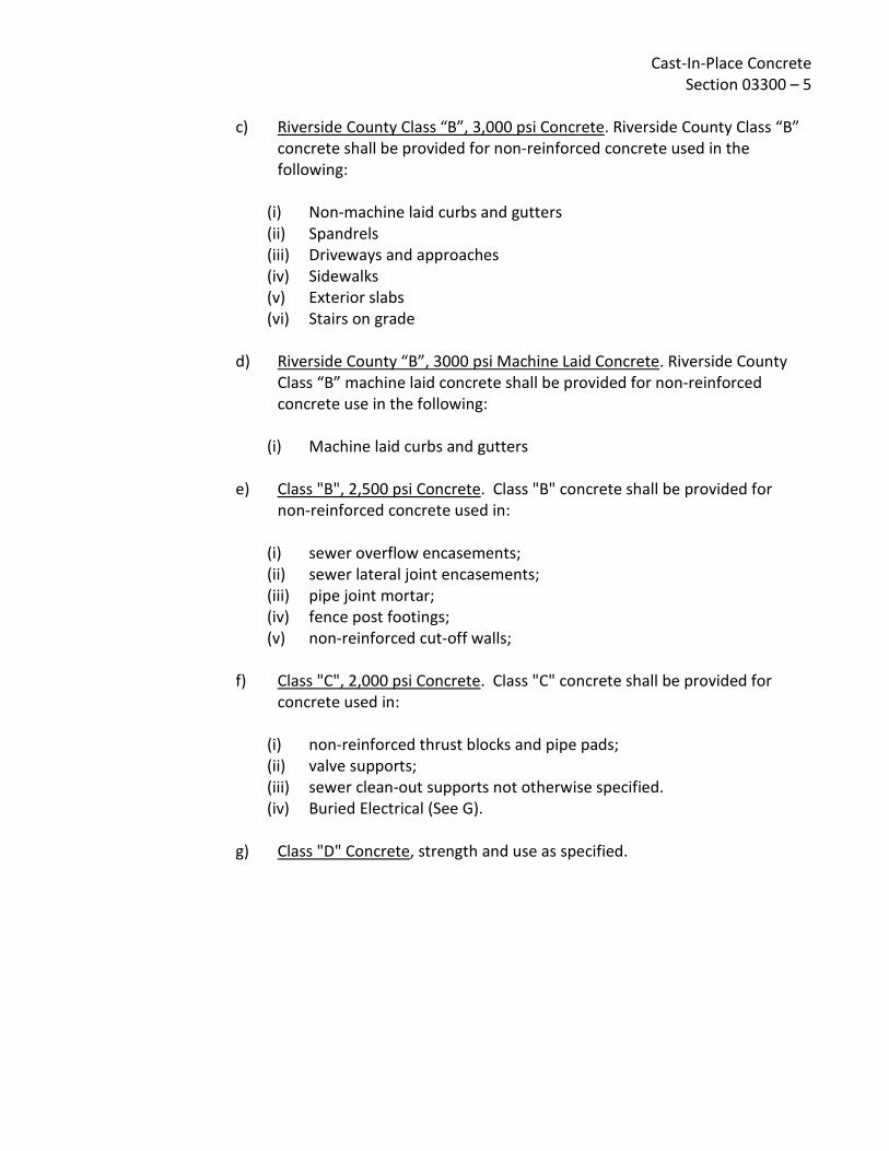
c) Riverside County Class “B”, 3,000 psi Concrete. Riverside County Class “B”
concrete shall be provided for non-reinforced concrete used in the following:
(i) Non-machine laid curbs and gutters (ii) Spandrels (iii) Driveways and approaches (iv) Sidewalks (v) Exterior slabs (vi) Stairs on grade
d) Riverside County “B”, 3000 psi Machine Laid Concrete. Riverside County Class “B” machine laid concrete shall be provided for non-reinforced concrete use in the following:
(i) Machine laid curbs and gutters
e) Class "B", 2,500 psi Concrete. Class "B" concrete shall be provided for non-reinforced concrete used in:
(i) sewer overflow encasements; (ii) sewer lateral joint encasements; (iii) pipe joint mortar; (iv) fence post footings; (v) non-reinforced cut-off walls;
f) Class "C", 2,000 psi Concrete. Class "C" concrete shall be provided for concrete used in:
(i) non-reinforced thrust blocks and pipe pads; (ii) valve supports; (iii) sewer clean-out supports not otherwise specified. (iv) Buried Electrical (See G).
g) Class "D" Concrete, strength and use as specified.

Cast-In-Place Concrete Section 03300 – 6
(i) Basis for Mix Designs. Design concrete mixes for workability of mix and durability of concrete. Concrete mixes shall be rigidly controlled in accordance with laboratory trial batch method or combinations of materials previously evaluated as required by Sections 5.3, respectively, Standard Building Code Requirements for Reinforced Concrete (ACI 318, latest edition), of the American Concrete Institute and to satisfy herein specified concrete strength requirements. When, in the opinion of the Engineer, it becomes necessary to increase the cement content to gain the required strength, such adjustment shall be made at the Contractor's expense.
(ii) Water/Cement Ratios. Mixes for normal weight aggregate concrete shall be designed within the following maximum water/cement ratios when concrete is to be used in the various locations: For 4,000 psi water-bearing structural concrete limit water/cement
ratios by weight as follows: Freshwater-bearing structures 0.48 maximum Sewage-bearing structures 0.45 maximum
For all other concrete, water/cement ratios shall be no greater than 0.53, except EMWD mixes and Riverside County mixes listed in Section 2.02.
B. Preliminary Strength Tests. In laboratory, prepare nine (9) compression test cylinders
for each concrete mix design (unless more tests are required for an earlier age). Fabricate and cure cylinders in accordance with ASTM C3l. Use concrete, aggregates and admixtures proposed for the concrete work. In accordance with ASTM C39, test three sets of two cylinders at 28-day age. For each mix, no individual strength test result shall fall below the required fc'.
C. Drying Shrinkage Tests. For each mix design used for preliminary strength tests, using same concrete materials including admixtures, prepare three (3) test specimens for drying shrinkage testing. Specimens shall be 4 inch by 4 inch by 11 inch prisms fabricated, cured, and tested in accordance with ASTM C157, using 10 inch effective gauge length. Measurements shall be taken at one (1) day, seven (7) days, fourteen (14) days and twenty-one (21) days of curing. Zero measurement shall be the one day reading when determining shrinkage. The measurements after 7, 14, and 21 days of drying shall be taken and reported separately. The average drying shrinkage of each set of test specimens after two (2) days of drying shall not exceed 0.036% for concrete in all portions of water-bearing structures and not exceed 0.05% for all other structural concrete, except concrete for footings, piles and pile caps will not require drying shrinkage tests. Single specimens shall be within a tolerance of 25% of said maximum percentage.

Cast-In-Place Concrete Section 03300 – 7
D. Reports. File each mix design, preliminary strength test report, and drying shrinkage test report with District for review and approval. Contractor shall submit a letter of certification by an approved testing laboratory that the concrete materials, mixes, properties, and work conform to the requirements indicated and specified.
1.05 PRODUCT DELIVERY, STORAGE, AND HANDLING Deliver materials in a timely manner to insure uninterrupted progress of work. Store materials in a manner that will preclude damage and permit ready access for inspection and identification.
A. Materials for treatment of concrete surfaces. The contractor shall deliver sealers, coatings, waterproofing, or other surface treatment materials to the site in their original, unopened containers with the manufacturer's labels intact, describing contents and manufacturer. Stored materials shall be kept covered and precautions shall be taken for the prevention of fire. Empty containers and soiled or oily rags shall be removed from the site at the end of each day's work.
1.06 PAYMENT Payment for cast-in-place concrete shall be based upon concrete poured and found acceptable upon the removal of forms and performance of required finishing. Under no conditions will more than 90% payment be made for concrete formed and poured until required finishing is completed. On large structures requiring construction over multiple payment periods, consideration may be given by the Engineer for payment as follows:
A. Forms and rebar in place and accepted for concrete pour - 50% maximum of concrete price per cubic yard.
B. Concrete poured and forms stripped, and found acceptable to the stage of construction - 35% maximum of concrete price per cubic yard.
C. Concrete finished and found acceptable - 15% of concrete price per cubic yard.

Cast-In-Place Concrete Section 03300 – 8 PART 2 - PRODUCT
2.01 MATERIALS.
A. Portland Cement. Standard brand of domestic Portland cement, ASTM C150, Type II, low alkali. Do not change brand of cement during progress of work without written approval of Engineer. For concrete exposed to sulfate-containing soils, solutions or other chemically aggressive solutions, use Type V Portland cement as specified.
B. Normal Weight (Stone) Aggregates. Furnish natural aggregates from approved pits, free from opaline, chert, feldspar, mica (fools gold), siliceous magnesium limestone or other deleterious or reactive substances. Conform to ASTM C33 except as modified herein. Fine aggregates shall pass a #4 sieve. Do not use pozzolan or other additives to compensate for aggregate alkali reactivity. 1. Coarse Aggregates. Clean, hard, fine-grained sound crushed rock or washed
gravel which does not contain in excess of 5% in weight of flat, chip-like, thin, elongated, friable or laminated pieces, or more than 2% by weight of total amount of cherty material and soft particles, or more than 1% of chert as soft material as defined on Table 3 of ASTM C33. Consider any piece having a major dimension in excess of 5 times its average dimension to be flat or elongated.
2. Maximum Sizes. As indicated on Drawings, except for concrete in water-bearing structures where coarse aggregate sizes per Table 2 of ASTM C33 shall be No. 467 (1½ inches), No. 57 (1 inch), or No. 67 (3/4 inch) as otherwise required by design, specifications and ASTM C33, and except that coarse aggregate nominal maximum size shall not exceed one-fifth the narrowest dimension between sides of form, one-third the depth of slabs, or three-fourths of minimum clear spacing between reinforcing bars.
3. Quality. All aggregates shall meet the test requirements of Article "Source Quality Control" hereinbefore.
4. Abrasive Aggregate. "Alundum" by Norton Company, "Carborundum" by Union Carbide, or equal aluminum oxide, uniformly graded between No. 12 and No. 30 sieves, applied uniformly at minimum rate of 1/4 lb. per sq. ft. and locked into cement matrix with the final troweling.
C. Admixtures. Use one manufacturer's products throughout. Upon Engineer's approval
of use and of a particular brand or type, assure that use is reflected in mix designs. Approved manufactures are W.R. Grace and Master Builder Products.
Cast-In-Place Concrete Section 03300 – 9
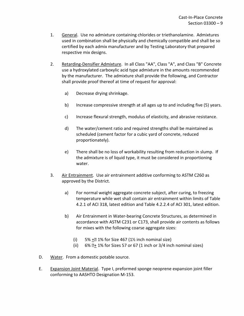
1. General. Use no admixture containing chlorides or triethanolamine. Admixtures
used in combination shall be physically and chemically compatible and shall be so certified by each admix manufacturer and by Testing Laboratory that prepared respective mix designs.
2. Retarding-Densifier Admixture. In all Class "AA", Class "A", and Class "B" Concrete use a hydroxylated carboxylic acid type admixture in the amounts recommended by the manufacturer. The admixture shall provide the following, and Contractor shall provide proof thereof at time of request for approval:
a) Decrease drying shrinkage.
b) Increase compressive strength at all ages up to and including five (5) years.
c) Increase flexural strength, modulus of elasticity, and abrasive resistance.
d) The water/cement ratio and required strengths shall be maintained as scheduled (cement factor for a cubic yard of concrete, reduced proportionately).
e) There shall be no loss of workability resulting from reduction in slump. If
the admixture is of liquid type, it must be considered in proportioning water.
3. Air Entrainment. Use air entrainment additive conforming to ASTM C260 as
approved by the District.
a) For normal weight aggregate concrete subject, after curing, to freezing temperature while wet shall contain air entrainment within limits of Table 4.2.1 of ACI 318, latest edition and Table 4.2.2.4 of ACI 301, latest edition.
b) Air Entrainment in Water-bearing Concrete Structures, as determined in
accordance with ASTM C231 or C173, shall provide air contents as follows for mixes with the following coarse aggregate sizes:
(i) 5% + 1% for Size 467 (1½ inch nominal size) (ii) 6% + 1% for Sizes 57 or 67 (1 inch or 3/4 inch nominal sizes)
D. Water. From a domestic potable source.
E. Expansion Joint Material. Type I, preformed sponge neoprene expansion joint filler
conforming to AASHTO Designation M-153.

Cast-In-Place Concrete Section 03300 – 10
F. Bituminous Mastic. For fills at specific designated locations (such as fills at precast panel lift-eyes and dowel hole fills in precast concrete panels) use either Hot-Applied Type Joint Sealer, ASTM D1190 or Cold-Applied Type Joint Sealant, ASTM D1850. Material shall bond to concrete, prevent moisture infiltration and when set, shall be non-tracking at summer temperatures.
G. Waterstops. Waterstops shall be produced by an extrusion process in such a manner that any cross section shall be dense, homogeneous and free from porosity and other imperfections. They shall be symmetrical in cross-sectional shape and uniform along their length. The manufacturer must certify in writing that all waterstops are extruded from elastomeric polyvinyl chloride compound and that this compound shall be virgin PVC compound and not contain any scrap or reprocessed materials whatsoever. The manufacturer must also certify in writing that all waterstops meet or exceed the physical properties requirements set forth in the U.S. Corps of Engineers' CRD-C572-74 specification and include a copy of certified independent laboratory test data showing compliance. All waterstop intersections (ells, tees, crosses, etc.) shall be fabricated by the manufacturer and these shall have 2 ft. long legs to facilitate field butt splicing. Where field dimensions are encountered which will not accommodate the specified waterstop, waterstop of reduced dimension may be approved by the Engineer for a specific application.
H. Concrete Joint Sealants. For sealing joints in nonwater-bearing concrete surfaces, use materials conforming with requirements specified in Section 07920, "Sealants and Caulking". For sealing concrete joints which will be immersed or intermittently immersed in water or sewage-bearing surfaces, use: Karlee Company's "Lastex M" 100 percent solids polyurethane sealant; Mameco International's Vulkem 227, Vulkem 45, or Vulkem 245 contingent upon need for self-leveling, non-sag and atmospheric humidity at time of usage; Hunt's Seal Flex 227-U Special Reservoir Grade polyurethane sealant; or equal. 1. Primer. Use primer produced and/or recommended by sealant manufacturer.
2. Back-up Preformed Joint Filler. Use closed-cell polyethylene foam or equal
impervious, compatible, compressible foam material recommended for retaining sealant depth in expansion joints while curing. Use no bitumen or oil saturated material.

Cast-In-Place Concrete Section 03300 – 11
3. Bond Breakers. Bond breakers, where required, shall be polyethylene tape or
equal as recommended by sealant manufacturer to prevent adherence of sealant to back-up material.
I. Dry Pack Mortar. Dry pack mortar shall consist of by volume one part special cement, three parts sand and water. The special cement and sand shall be combined in the proper proportions and then thoroughly mixed with the required amount of water. The dry pack mortar shall contain only enough water to permit placing and packing and shall be mixed for the time limit as indicated by the manufacturer in advance of use. The dry pack mortar shall be placed against thoroughly wet concrete and shall be cured by water, fog spray, spray-on membranes, sisal kraft paper, or other curing method acceptable to the District.
J. Grout. Grout to be applied to the concrete surface shall consist of one part Portland Cement to three parts dry, washed sand to sufficient water to allow placement, screening, and finishing.
K. Rich Grout. Rich grout shall consist of by volume one part Portland Cement, two parts sand and water. The rich grout shall be mixed and cured in the same manner as required for dry pack mortar.
L. Neat Grout. Neat grout shall consist of Portland Cement, flyash, water and optional admixtures. Neat grout is intended to be injected under low pressure to backfill the annular space between steel casing pipes and carrier pipes.
M. Nonshrink Grout. Nonshrink grout shall be made with the following proportions:
One part Type II Portland Cement (one sack); One part Nonshrink Aggregate (100 lbs.); One part clean, well graded concrete sand (100 lbs.); Approximately 5.5 gallons of water per sack of cement 1. In all locations where the surface of the grout will be exposed to view, the
nonshrink grout shall be recessed approximately one-half inch back of the exposed surface and the recessed area filled with cement mortar grout.
N. Nonshrink Concrete. All nonshrink concrete shall contain one pound of nonshrink
aggregate per pound of water that is in excess of two gallons per sack of cement. Recess surface exposed to field as specified for nonshrink grout above.
O. Nonshrink Aggregate. Nonshrink aggregate shall be non-metallic as produced by Master Builders, an equivalent product of Sonneborn, or a product by any other manufacturer that will meet the same ASTM requirements and equal performance.

Cast-In-Place Concrete Section 03300 – 12
P. Epoxy. Epoxies for grouting, crack repair, patching, bonding or other uses shall be as follows as manufactured by Adhesive Engineering Company, Sika Chemical Company, or equal by other manufacturer. Throughout, use products of single manufacturer. 1. All epoxy mixing, surface preparation and application shall be made in
conformance with manufacturer's printed specifications, as approved by the Engineer.
2. For bonding new concrete to old concrete and for grouting metal anchors, use Sika's "Sikadur Hi-Mod", Adhesive Engineering Company's Concresive 1001-LPL, except Concresive 1170 or 1422 shall be used as recommended by manufacturer to satisfy entailed project temperature and surface moisture variations at time of application; or equal.
3. For patching concrete surfaces, making high strength epoxy concrete or grout, and grouting metal anchors, use Sika's "Sikadur Hi-Mod LV"; Adhesive Engineering Company's "Concresive 1180"; or equal.
4. For pressure injection or gravity-feed grouting, use Sika's "Hi-Mod LV"; Adhesive Engineering Company's "Concresive Structural Concrete Bonding Process System" as recommended by manufacturer and approved by Engineer; or equal.
Q. Liquid Curing Compound. Use "TLF" or "Clear 225 TU" by Hunt Process Company, Burke
"Rez-X", or equal conforming to ASTM C309 and providing no detrimental affects with deferred finishes. On surfaces within reservoirs or other concrete structures containing potable water, use nontoxic materials which are free of odor and taste. Provide supporting technical data. Floor hardener treated floors shall use materials only as recommended in writing by hardener manufacturer.
R. Sheet Curing Materials. ASTM C171, waterproof paper, polyethylene film or white burlap-polyethylene sheet, non-staining.
S. Vapor Barrier Membrane. Under interior on-grade slabs of occupied areas provide lapped and sealed vapor barrier membrane using Fortiber "Moistop", "Damproof XX" by Nicolet of California, Incorporated, or equal with manufacturer's recommended polyethylene pressure sensitive tape sealant used continuously at lapped joints, penetrations and at perimeter walls or footing surfaces. Throughout, use products and system of single manufacturer.

Cast-In-Place Concrete Section 03300 – 13
T. Gasket Seal for Manhole and Wet Well Precast Concrete Members. Provide gasket seals
at mating joint of precast concrete sections. Size gaskets to suit joint dimensions, surface conditions and to assure watertight completed installation. Seal shall consist of either compressible closed-cell neoprene rods with compatible bonding agent recommended by material manufacturer; of No. 95 extruded butyl rod and No. 2 Primer each produced by General Sealants, Incorporated, City of Industry, California; or equal non-bituminous joint sealing compressible gaskets.
U. Synthetic Sponge Rubber Filler. Synthetic rubber filler shall be an expanded closed-cell sponge rubber, manufactured from a synthetic polymer neoprene base. The material shall be No. 750.3 Ropax Road Stock as manufactured by the Presstite Division of Interchemical Corporation; Bondtex as manufactured by Rubatex Corporation; or approved equal. The size of the material shall be 25% greater in diameter than the nominal joint width. The manufacturer's instructions for surface preparation and application shall be used as a guide for installation, except that the material shall not be installed by stretching beyond its normal length.
V. Expansion Joint Filler. Bituminous fiber expansion joint filler shall be in accordance with ASTM D1751. Bituminous expansion joint material shall not be used in joints to be sealed with synthetic rubber sealing compound.
W. Concrete Expansion Bolts/Deferred Bolting Device (D.B.D.). Except as otherwise specified, where expansion bolts are called for on the Drawings, Parabolt Concrete Anchors as manufactured by the Molly Company, Kwik-Bolts as manufactured by McCulloch Industries, Incorporated, or a concrete anchor by any other manufacturer that shall meet the same Federal Specification requirements and shall equal the performance, shall be used. All bolts thus furnished and used on this project shall be manufactured of stainless steel.
2.02 CONCRETE MIXES
A. 28-Day Compressive Strength. It shall be the sole responsibility of the Contractor to mix, place, and cure concrete which shall be of 150 lb./cu.ft. nominal density and which shall attain the compressive strengths at 28 days as designated on Structural Drawings or in these specifications for use in various locations. 110695
B. Maximum Aggregate Size. Conform to Article 2.01 B.2. For Class "AA" concrete use 1½ inch maximum size aggregate unless otherwise designated; for Class "A" and Class "B" use 1 inch maximum size aggregate; for Class "C" and Class "D" use 3/4 inch maximum size aggregate. In no case shall the size of the coarse aggregate exceed 75% of the horizontal space between reinforcing bars or between reinforcing bars and forms.
Cast-In-Place Concrete Section 03300 – 14
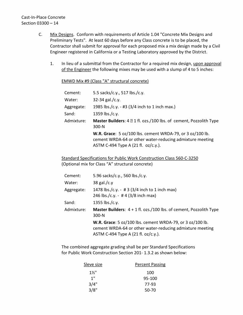
C. Mix Designs. Conform with requirements of Article 1.04 "Concrete Mix Designs and Preliminary Tests". At least 60 days before any Class concrete is to be placed, the Contractor shall submit for approval for each proposed mix a mix design made by a Civil Engineer registered in California or a Testing Laboratory approved by the District.
1. In lieu of a submittal from the Contractor for a required mix design, upon approval
of the Engineer the following mixes may be used with a slump of 4 to 5 inches: EMWD Mix #9 (Class "A" structural concrete)
Cement: 5.5 sacks/c.y., 517 lbs./c.y. Water: 32-34 gal./c.y. Aggregate: 1985 lbs./c.y. - #3 (3/4 inch to 1 inch max.) Sand: 1359 lbs./c.y. Admixture: Master Builders: 4 1 fl. ozs./100 lbs. of cement, Pozzolith Type
300-N W.R. Grace: 5 oz/100 lbs. cement WRDA-79, or 3 oz/100 lb. cement WRDA-64 or other water-reducing admixture meeting ASTM C-494 Type A (21 fl. oz/c.y.).
Standard Specifications for Public Work Construction Class 560-C-3250 (Optional mix for Class “A” structural concrete)
Cement: 5.96 sacks/c.y., 560 lbs./c.y. Water: 38 gal./c.y Aggregate: 1478 lbs./c.y. - # 3 (3/4 inch to 1 inch max)
246 lbs./c.y. - # 4 (3/8 inch max) Sand: 1355 lbs./c.y. Admixture: Master Builders: 4 + 1 fl. ozs./100 lbs. of cement, Pozzolith Type
300-N W.R. Grace: 5 oz/100 lbs. cement WRDA-79, or 3 oz/100 lb. cement WRDA-64 or other water-reducing admixture meeting ASTM C-494 Type A (21 fl. oz/c.y.).
The combined aggregate grading shall be per Standard Specifications for Public Work Construction Section 201- 1.3.2 as shown below:
Sleve size Percent Passing
1½" 100 1" 95-100
3/4" 77-93 3/8" 50-70

Cast-In-Place Concrete Section 03300 – 15
No. 4 39-51 No. 8 31-41
No. 16 22-32 No. 30 12-22 No. 50 3-9
No. 100 0-3 No. 200 0-2
EMWD Mix #6 (Class "B" concrete)
Cement: 4.7 sacks/c.y., 441.8 lbs./c.y. Water: 30-32 gal./c.y. Aggregate: 415 lbs./c.y. - #4 (3/8 inch max.)
795 lbs./c.y. - #3 (3/4 inch to 1 inch max.) 1006 lbs./c.y. - #2 (1½ inch max.)
Sand: 1230 lbs./c.y. Admixture: Master Builders: 4 1 fl. ozs./100 lbs. of cement, Pozzolith Type
300-N W.R. Grace: 5 oz/100 lb. cement WRDA-79, or 3 oz/100 lb. cement WRDA-64 or other water-reducing admixture meeting ASTM C-494 Type A (18 fl. oz/c.y.).
Riverside County Class “B” Concrete
Cement: 5.5 sacks/c.y., 517 lbs./c.y. Water: 36.5 Gal./c.y. Course Agg. 1" x #4: 1559 lbs./c.y. Course Agg. 3/8" x #8: 226 lbs./c.y. Sand: 1434 lbs./c.y. Water Cement Ratio: 0.59 max. Slump: 4" max.
Course aggregate shall meet the grading requirements of ASTM C33. The combined aggregate grading shall be per Caltrans Standard Specification 90-3.04(1"max), as shown below:
Sleve size Percent Passing
1½" 100 1" 95-100
3/4" 55-100

Cast-In-Place Concrete Section 03300 – 16
3/8" 45-75 No. 4 35-60 No. 8 27-45
No. 16 20-35 No. 30 12-25 No. 50 5-15
No. 100 1-8 No. 200 0-4
Riverside County Class “B” Machine Laid Concrete
Cement: 5.5 sacks/c.y., 517 lbs./c.y. Water: 34.0 Gal./c.y. Course Agg. 1" x #4: 1388 lbs./c.y. Course Agg. 3/8" x #8: 295 lbs./c.y. Sand: 1589 lbs./c.y Water Cement Ratio: 0.55 max. Slump: 2" max
Course aggregate shall meet the grading requirements of ASTM C33. The combined aggregate grading shall be per Caltrans Standard Specification 90-3.04(1"max), as shown below:
Sleve size Percent Passing
1½" 100 1" 95-100
3/4" 55-100 3/8" 45-75 No. 4 35-60 No. 8 27-45
No. 16 20-35 No. 30 12-25 No. 50 5-15
No. 100 1-8 No. 200 0-4

Cast-In-Place Concrete Section 03300 – 17
EMWD Mix #10 (Class "C" concrete)
Cement: 4.5 sacks/c.y., 423 lb./c.y. Water: 32-34 gal./c.y. Aggregate: 1903 lb./c.y. Sand: 1480 lb./c.y. Admixture: None
2.03 CONCRETE MIXING Concrete shall be ready-mixed, supplied from an off-site commercial ready-mix plant approved by District, each load accompanied by a bonded weighmaster's certificate listing the quantity of each concrete ingredient, admixture quantity, water content and slump, and time of loading and departure from ready-mix plant. Also include notations to indicate equipment was checked and found to be free of contaminants prior to batching.
A. Ready-Mixed Concrete. Unless approved otherwise in advance of batching, all concrete of a single design mix for any one day's pour shall be from a single batch plant of a single supplier. Conform to ASTM C94, except materials, testing and mix design shall be as specified herein. Use transit mixers equipped with automatic devices for recording number of revolutions of drum. All applicable mixing requirements specified herein for concrete mixed at the site shall govern transit-mixed concrete and the District shall have free access to the batching plant at all times. For concrete mixed in top-loading truck mixers, each batch shall be turned not less than 40 and not more than 300 revolutions of the mixer drum at mixing speed when the fine and coarse aggregate are charged into the mixer simultaneously (cement and water may be charged separately). When the fine and coarse aggregate are charged into the mixer separately, each batch shall be turned not less than 60 and not more than 300 revolutions of the drum at mixing speeds. For concrete mixed in end-loading truck mixers, each batch shall be turned not less than 60 and not more than 300 revolutions of the mixer drum at mixing speed when the mixer is loaded in excess of 50 percent of the gross drum volume as provided hereinafter. When the mixer is loaded (not to exceed 50 percent of the gross drum volume) the provisions specified for top-loading truck mixers will apply. Truck mixers shall be loaded in accordance with manufacturer's capacity ratings, but in no case shall the volume of mixed concrete exceed 50 percent of the gross volume of the drum for top-loading mixers and 58 percent of the gross volume of the drum for end-loading truck mixers.

Cast-In-Place Concrete Section 03300 – 18
Mixing speed shall be in accordance with manufacturer's recommendations, but in no case shall the speed be less than 4 revolutions per minute or greater than a speed resulting in a peripheral velocity of the drum of 225 feet per minute. The power unit shall be equipped with a governor to insure constant speed. Each truck mixer shall be equipped with a device for counting the number of revolutions of the drum, which device shall be interlocked so as to prevent the discharge of concrete from the drum before the required number of turns. After the drum is once started, it shall be revolved continuously until it has completely discharged its batch. Water shall not be admitted to the mix until the drum has started revolving. The right is reserved to increase the required minimum number of revolutions or to decrease the designated maximum number of revolutions allowed, if necessary, to obtain satisfactory mixing, and the Contractor will not be entitled to additional compensation because of such increase or decrease.
B. Mixing Water Limitations. If water is added at the batching plant, ready-mixed concrete shall not be held in the mixer for more than one and one-half hours from the time the water is added. When temperature of concrete is 85°F or above, reduce holding time to 45 minutes. Do not deliver ready-mixed concrete to job with total specified amount of water incorporated therein. Without 2½ gallons of water per cubic yard, then incorporate in mix before concrete is discharged from mixer truck. If no water is added at the batching plant, measured quantities of water shall be added at the site and a minimum of fifteen minutes mixing given, or mixing to overcome segregation. Adding of water shall be under observation of Inspector. Each mixer truck shall arrive at the job site with its water container full. In event container is not full or concrete tests to a greater slump than specified, the load is subject to rejection.
C. Job Mixed Concrete. Contractor shall obtain the approval of the District for equipment and procedures proposed for job mixed concrete.
D. Consistency and Slump. Adjust quantity of water so concrete does not exceed maximum slumps specified when placed or specified water/cement ratio; use minimum necessary for workability required by the part of the structure being cast. Measure consistency of concrete in accordance with ASTM C143. Concrete exceeding maximum slump will be rejected. Part of Structure Maximum Slump
Footings and mass concrete not reinforced 3 inches
Slabs, and floors and reinforced footings 2 to 3 inches
Columns, walls over 8 inches thick 3 to 4 inches
Walls up to 8 inches thick 3 ½ to 4 inches
Equipment bases 3 to 5 inches

Cast-In-Place Concrete Section 03300 – 19
PART 3 - EXECUTION
3.01 PREPARATION BEFORE PLACING Remove excess water from forms before concrete is deposited. Divert any flow of water without washing over freshly deposited concrete. Remove hardened concrete, debris, and foreign materials from interior of forms and from inner surfaces of mixing and conveying equipment.
A. Forms. Prior to placing concrete, forms shall meet the requirements of Section 03150, as approved by the Engineer. Concrete to be poured on earthwork such as slabs or stairs on grade shall meet the same requirements for approval prior to pouring as above specified for the approval of forms.
B. Reinforcement. Reinforcement shall have been secured under work of Sections 03150 and 03200, and inspected and approved. Embedded metal shall be free of old mortar, oils, mill scale, and other encrustations or coatings that might reduce bond. Wheeled concrete-handling equipment shall not be wheeled over reinforcing nor shall runways be supported on reinforcing. "Break-out" bars or dowels bent for forming, for subsequent straightening prior to adjacent pour, will be allowed with bars of #5 maximum size, only where specifically called out on the Drawings, and only where kinks or breaks are not likely as a result of straightening. This does not imply approval of cold joints where none designed, or any deviation from construction joint requirements elsewhere in these specifications.
C. Wetting. Wet wood forms sufficiently to tighten up cracks. Wet other materials sufficiently to reduce suction and maintain concrete workability.
D. Earth Subgrade. Lightly dampened 24 hours in advance of concrete placing, but not muddied. Reroll as necessary for smoothness, and remove all loose materials.
E. Aggregate Fill Base. Prepare same as earth subgrade. Center 30-mil plastic sheeting or roofing cap sheet on base course under indicated waterstop joints to retain mix fines within mix and prevent their percolation into base course.

Cast-In-Place Concrete Section 03300 – 20 3.02 WATERSTOPS Heat fuse joints and connections in strict compliance with manufacturer's instructions including heating tools and devices. Waterstops shall be continuous in joints, following offsets and angles in joints until spliced to waterstops at intersecting joints, completely sealing the structure. Waterstops shall be aligned and centered in joints. Secure flanges of waterstops to reinforcing bars with 18 gage wire ties spaced maximum 18 inch center. All waterstops, splices, joints, intersections, and welds shall be tested with an approved holiday spark tester before concrete is placed. The contract drawings do not indicate every location that is to have waterstop. Waterstop shall be located in all water bearing structure walls and slabs. Waterstop shall be positioned correctly during installation and all splices in length or at intersections shall be performed by heat sealing and in accordance with manufacturer's recommendations. Waterstop joints shall conform to Drawing requirements, if requirements are shown on the Drawings, and, whether or not requirements are shown on the Drawings, shall be properly heat-spliced at ends and crosses to preserve continuity. All splicing shall be done using mitered joints. Forms for construction joints shall be constructed in such manner as to prevent injury to waterstops. Waterstops shall be securely held in position in the construction joints by wire ties. In narrow walls requiring both rebar and waterstop, the rebar shall be offset to one side and the keyway and/or waterstop shall be offset to the opposite side sufficiently to allow placement of both rebar and waterstop without contact. In order to accommodate such an offset, double curtain steel may be replaced by one properly designed larger bar upon approval by the Engineer. All in-place waterstop installations including locations and joints shall be approved by District prior to placement of concrete.
3.03 JOINTS IN CONCRETE Locate joints in concrete where indicated unless otherwise approved. Obtain approval of points of stoppage of any pour, prior to scheduling of pour.
A. Construction Joints. Unless otherwise shown, all construction joints shall be provided with suitable keyways or other keying methods. Clean and roughen contact surfaces of construction joints by removing entire surface and exposing clean aggregate solidly embedded in mortar matrix. Use mechanical chipping, sandblasting, or application of surface mortar retarder followed by washing and scrubbing with stiff broom. Cover and protect waterstops and other inserts from damage. Where construction joints are not indicated on the Drawings, provide slabs and walls with construction joints at intervals not greater than 30 feet. Starter walls shall be used unless detailed otherwise. Where utilized, starter walls shall extend a minimum of 3½ inches.
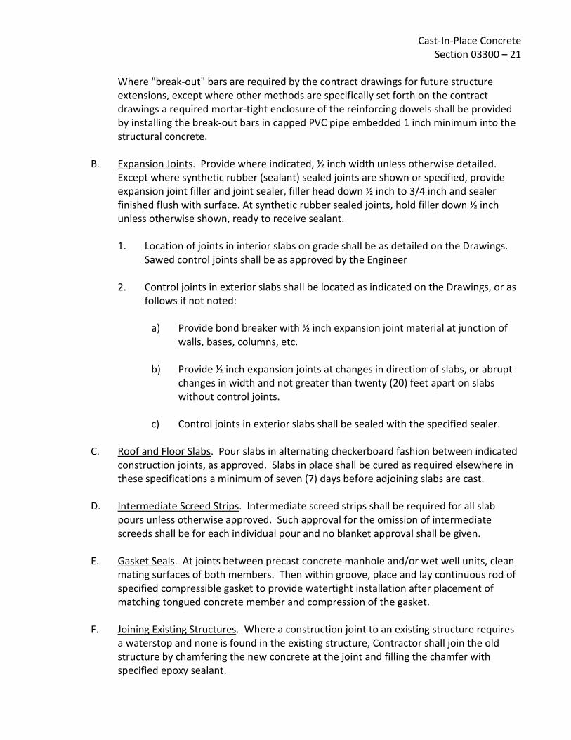
Cast-In-Place Concrete Section 03300 – 21
Where "break-out" bars are required by the contract drawings for future structure extensions, except where other methods are specifically set forth on the contract drawings a required mortar-tight enclosure of the reinforcing dowels shall be provided by installing the break-out bars in capped PVC pipe embedded 1 inch minimum into the structural concrete.
B. Expansion Joints. Provide where indicated, ½ inch width unless otherwise detailed. Except where synthetic rubber (sealant) sealed joints are shown or specified, provide expansion joint filler and joint sealer, filler head down ½ inch to 3/4 inch and sealer finished flush with surface. At synthetic rubber sealed joints, hold filler down ½ inch unless otherwise shown, ready to receive sealant. 1. Location of joints in interior slabs on grade shall be as detailed on the Drawings.
Sawed control joints shall be as approved by the Engineer
2. Control joints in exterior slabs shall be located as indicated on the Drawings, or as follows if not noted:
a) Provide bond breaker with ½ inch expansion joint material at junction of walls, bases, columns, etc.
b) Provide ½ inch expansion joints at changes in direction of slabs, or abrupt
changes in width and not greater than twenty (20) feet apart on slabs without control joints.
c) Control joints in exterior slabs shall be sealed with the specified sealer.
C. Roof and Floor Slabs. Pour slabs in alternating checkerboard fashion between indicated
construction joints, as approved. Slabs in place shall be cured as required elsewhere in these specifications a minimum of seven (7) days before adjoining slabs are cast.
D. Intermediate Screed Strips. Intermediate screed strips shall be required for all slab pours unless otherwise approved. Such approval for the omission of intermediate screeds shall be for each individual pour and no blanket approval shall be given.
E. Gasket Seals. At joints between precast concrete manhole and/or wet well units, clean mating surfaces of both members. Then within groove, place and lay continuous rod of specified compressible gasket to provide watertight installation after placement of matching tongued concrete member and compression of the gasket.
F. Joining Existing Structures. Where a construction joint to an existing structure requires a waterstop and none is found in the existing structure, Contractor shall join the old structure by chamfering the new concrete at the joint and filling the chamfer with specified epoxy sealant.

Cast-In-Place Concrete Section 03300 – 22
Where required reinforcing is not found protruding from the existing structure, required reinforcing shall be placed by drilling and placing dowels of the proper size and spacing. Where required waterstop and reinforcing is found in the existing structure, joints shall be treated as other construction joints under Articles 3.01 and 3.02.
G. Concrete for Buried Electrical. Buried electrical ducts, conduits & similar type items are to be encased in Class C red colored concrete as disignated below. Aggregate for Class C Concrete for Encasement of Electrical Conduits: 1. Graded as specified in ASTM C 33, Size Number 8. 2. Provide concrete utilizing this aggregate equal to Class C concrete in all other
respects. 3. Manufacturers: Frank D. Davis Company, Red Oxide Number 1117 or equal.
3.04 CONVEYING AND PLACING CONCRETE
A. Do not pour concrete until reinforcing steel and forms have been inspected and approved. Notify District not less than one full working day in advance of readiness for inspection of forms and reinforcing. Specific approval of individual forms by the Engineer shall be obtained before ordering of concrete. The Contractor shall give the Engineer a minimum of 24 hours notice of a scheduled concrete pour following the completion of forming. Upon inspection of the forms, reinforcing, waterstop placement, etc., the Engineer will immediately issue a written approval to pour concrete showing approval of the scheduled pour or disapproval. In the event of disapproval, the Engineer will show the Contractor the specific deficiencies, for correction within the 24 hour period prior to the scheduled pour. Upon notification by the Contractor of correction of deficiencies and reinspection and approval by the Engineer, the pour may proceed as scheduled. In the event required corrections are not made, or are not approved, the disapproval of the pour shall stand and the pour shall not proceed as scheduled, but shall be rescheduled. Any concrete not in accordance with these specifications, out of line, level, or plumb; or showing cracks, rock pockets, voids, stalls, honeycombing, exposure of reinforcing, or any other damage which will be detrimental to the work will be considered defective and must be corrected and replaced as directed by the Engineer at no additional cost to the District. Any concrete work that is not formed as indicated; is not true within 1/250th of the span; is not true to intended alignment; is not plumb or level where so intended; is not true to intended grades and levels; has voids or honeycombs that have been cut, resurfaced or filled, unless under the direction of the Engineer; has any

Cast-In-Place Concrete Section 03300 – 23
sawdust, shavings, wood or embedded debris; or does not fully conform to the contract provisions, shall be deemed to be defective and shall be removed from the site. 1. Handle or pump no concrete utilizing aluminum equipment.
2. Delivery tickets shall show the following:
a) Batch number.
b) Mix by compressive strength with maximum aggregate size.
c) Types and amount of admixtures included.
d) Air content.
e) Slump.
f) Time of loading and discharge.
g) Amount of water put in at batch plant.
h) Location in the work.
i) Specification class of concrete.
j) Date of delivery.
3. If any water is added at the job site, it shall be approved by the Engineer and the
delivery ticket noted as to the amount of water added. One copy of each delivery ticket shall be submitted daily to the Engineer.
B. Weather. Do not place concrete during rain or freezing weather unless approved
measures are taken to prevent damage to concrete. Concrete placed during periods of dry winds, low humidity, high temperatures, and other conditions causing rapid drying shall be initially cured with a fine fog spray of water applied immediately after finishing and maintained until final curing operations are started. Also under hot weather conditions, steps shall be taken to reduce concrete temperatures and water evaporation by proper attention to ingredients, production methods, handling, placing, protection, and curing.
Cast-In-Place Concrete Section 03300 – 24
1. Preventative measures taken for concrete placement during hot or cold weather shall be approved by the Engineer. There shall be no placing of concrete when ambient temperatures are below 35°F or above 100°F, or when such will be the case within 24 hours of the pour. Any concrete previously placed shall be protected from freezing.
C. Conveying. Do not drop concrete from its point of release at mixer, hopper, tremies, or
conveyances more than 6 feet, nor through reinforcing bars in a manner that causes segregation. Provide form windows, tremies, elephant trunks, and equivalent devices as required. The use of chutes for conveying or depositing concrete is not allowed except for small isolated portions of the work and only with prior approval. Deposit concrete directly into conveyances and from conveyances to final points of repose. Deposit concrete so that the surface is kept level throughout, a minimum being permitted to flow from one portion to another.
D. Placing Concrete. Concrete shall be placed and compacted within 90 minutes after water is first added to the mix, and no concrete shall be placed after there is evidence of initial set. This placing time shall be reduced to 45 minutes when the temperature of the concrete is 85°F or above. Retempering of concrete is not allowed. 1. Horizontal Construction Joints. Horizontal surfaces of previously placed and
hardened concrete shall be wet and covered with a 6 inch thick layer of concrete of the design mix with 50% of coarse aggregate omitted just before balance of concrete is placed.
2. Lifts. Pour concrete into forms immediately after mixing in a manner that will prevent separation of ingredients. Except as interrupted by joints, all formed concrete shall be placed in continuous, approximately horizontal layers, the depths of which generally shall not exceed 18 inches.
a) Walls and Slabs. In order to minimize the effects of shrinkage, concrete
shall be placed in units bounded by construction joints. The placing of units shall be done by placing alternate units in a manner such that each unit placed shall have cured at least 7 days for hydraulic structures and 3 days for all other structures before the contiguous unit or units are placed. The exception is corner sections of vertical walls, which shall not be placed until the adjacent wall panels have cured at least 14 days for hydraulic structures and 4 days for all other structures.
b) Beams and Slabs. Pouring of all beams and slabs must be continuous and monolithic with the floor system where so shown on the Drawings. At least two (2) hours must elapse after depositing concrete in walls or columns before pouring beams, etc. supported thereon.
Cast-In-Place Concrete Section 03300 – 25
3. Pumping Concrete. No increase in the specified slumps will be allowed and
required water/cement ratios shall be maintained for concrete pumping. Aluminum tubes are not acceptable for conveying concrete. Equipment shall be capable of maintaining the specified pour rates. Conform with requirements of ACI 304.2R-96, except as more stringent requirements are specified herein. Minimum conduit (tube) diameter shall be 4 inches.
4. Pour Rates.
a) Vertical Elements. Place concrete in lifts as specified at a rate that does not overstress forms nor allows the top of a lift to begin to harden before the next lift is placed. Cold joints are not acceptable.
b) Slabs. Place concrete at a rate that ensures all deposits are joined to
concrete that is still plastic and within 10 minutes of the previous pour. Concrete adjoining alternate slabs shall not be placed until the adjoining concrete has cured as required elsewhere in this specification for at least seven days unless otherwise approved by the Engineer.
5. Field Tests. During the progress of construction, the District will have tests made
to determine whether the concrete, as being produced, complies with the standards of quality specified herein. These tests will be made in accordance with ASTM C3l and ASTM C39. Each test will consist of a minimum of four cylinders, and the District, at his discretion, may take such tests as frequently as necessary to prove the quality of the concrete. In no case shall less than one test be made of each day's pour or of each 50 yards of concrete. The Contractor shall furnish the concrete for such tests but the remaining testing expense will be borne by the District. Specimens will be cured under job conditions. For all concrete, the standard age of test will be 28 days, but the 7-day test may be used provided that the relation between the 7 and 28 strengths of the concrete is established by tests for the materials and proportions used. Slump tests will be in accordance with ASTM Cl43. Enforcement of Strength Requirement. Concrete is expected to reach a higher compressive strength than that indicated as minimum compressive strength. At least the specified minimum cement shall be used, and more cement shall be used, if necessary, to meet all minimum and maximum requirements shown in the table. Failure to meet these conditions shall be considered failure of the concrete.

Cast-In-Place Concrete Section 03300 – 26
One test shall consist of the results of testing three (3) standard specimens in accordance with ASTM C3l and C39, except that if one specimen in a test shows manifest evidence of improper sampling, molding, or testing, it shall be discarded and the remaining two strengths averaged. Should more than one specimen presenting a given test show defects due to improper sampling, molding, or testing, the entire test shall be discarded. If the concrete fails to meet the specifications in the preceding paragraph, the District shall have the right to ask for additional curing of the affected portion followed by cores taken in accordance with ASTM C42 all at the Contractor's expense. If the additional curing does not bring the average of three cores taken in the affected area to at least the strength specified, the District may require strengthening of the affected portions of the structures by means of additional concrete or steel, or he may require replacement of these affected portions, all at the Contractor's expense. Core tests for below-strength concrete shall be paid for by the Contractor even though such core tests indicate the concrete has obtained the required minimum compressive strength.
E. Compaction. Effective compaction shall be obtained by vibration, agitation, spading,
and rodding until the concrete is free from voids, air bubbles, or rock pockets. Vibrators shall not be used to transport concrete within the forms. No less than one spare vibrator for each two vibrators in use on a pour, each in good working condition shall be kept on the job during pours. One experienced workman shall be assigned to the operation of each vibrator as his only duty. Operations not deemed to be satisfactory by the District shall be immediately corrected. 1. Vibration. All concrete, with the exception of concrete slabs 4 inches or less in
depth, shall be compacted with high frequency, internal mechanical vibrating equipment supplemented by hand spading and tamping. Concrete slabs 4 inches or less in depth shall be consolidated by wood or metal grid tampers, spading and settling with a heavy leveling straight edge. Carefully vibrate concrete around waterstops and ensure the waterstops are not bent or damaged.
a) Vibrators. Vibrators shall be designed to operate with vibratory element submerged in the concrete, and shall have a frequency of not less than 7,000 impulses per minute when submerged. The vibrating equipment shall be adequate at all times in number of units and power of each unit to consolidate the concrete to the maximum practicable density so that it is free from air pockets, honeycomb, entrapped air and so it closes snugly against all surfaces of forms and embedded items.

Cast-In-Place Concrete Section 03300 – 27
b) Operation of Vibrators. Do not allow vibrators to contact forms or
reinforcing. In vibrating a freshly placed layer of concrete, the vibrator shall be inserted vertically through the preceding layers that are still completely plastic and slowly withdrawn, producing the maximum obtainable density in the concrete without creating voids. Under no circumstances shall the vibrator enter or disturb concrete that has stiffened or partially set. The interval of vibrator placing shall not exceed two-thirds the effective visible vibration diameter of the submerged vibrator. Avoid excessive vibration that causes concrete segregation or causes an inordinant amount of entrained air to move to the face of the forms, which shall be causes for rejection of the concrete pour.
c) Re-Vibration of Retarded Concrete. Concrete containing retarding
admixture for structural walls and columns shall be placed by a schedule that allows each layer of concrete to be in place and compacted for at least 30 minutes before the next layer of concrete is placed. Bleed water on the surface of the concrete shall be removed before additional concrete is placed and the concrete in place re-vibrated before the next lift is placed. At tops of walls and columns concrete containing excess water or fine aggregate caused by vibration shall be removed while plastic, and the space filled with compacted concrete of the correct proportions, vibrated in place.
F. Slabs. Set screeds at maximum 8 foot centers, as approved, and verify correct
elevations with instrument level, and consideration for any camber in the form. Compact and tamp concrete to bring 3/8 inch mortar to surface, and wood float to straightedges and screeds. Make finished surfaces level or sloped as detailed, with maximum deviation of 1/4 inch from 10 feet straightedge for exposed finishes, and there shall be no low spots to impound water. Do not use steel or plastic floats of any kind of initial floating operations. Unless otherwise specified, do not apply hereinafter specified finishes until surface water disappears and surface is sufficiently hardened. Remove all bleed water and laitance as it appears.
G. Tolerances 1. Forms, sleeves, and inserts shall be set, and concrete shall be cast, to the lines and
grades indicated on the plans and as detailed in these specifications. The maximum deviation from true line and grade shall not exceed the tolerances listed in the following table.
Cast-In-Place Concrete Section 03300 – 28
Item Maximum Tolerance Sleeves and inserts +1/8 inch -1/8 inch
Projected ends of anchor bolts +1/4 inch -0.0 inch
Anchor bolt setting +1/16 inch -1/16 inch 2. Formed surface tolerances for concrete shall meet requirements for ACI surface
classes as follows, unless otherwise specified herein or in the Special Provisions. Class "A". Exposed interior and exterior concrete to be coated or painted.
Abrupt irregularities must meet a modified requirement of 1/16 inch maximum.*
Class "B". Coarse textured concrete intended to receive plaster, stucco or
wainscoting. Class "C". Exposed interior and exterior concrete not requiring coating or
painting. Class "D". Permanently concealed surfaces below permanent ground level
or operating water surface.
Permitted Irregularities in Formed Surfaces Checked with a 5-foot Template
Type of Irregularity
ACI Surface Tolerance Class of Surface
A B C D
Gradual 1/8 inch 1/4 inch ½ inch 1 inch
Abrupt *1/16 inch 1/4 inch 1/4 inch 1 inch
3. Deviation in alignment of slabs or walls shall not exceed a rate of l/8 inch in l0 feet
within the tolerances specified.
4. Slabs shall be uniformly sloped to drain.
5. Regardless of the tolerances listed herein, it shall be the responsibility of the Contractor to limit deviations in line and grade to tolerances which will permit proper installation and operation of mechanical equipment and piping.

Cast-In-Place Concrete Section 03300 – 29
3.05 CURING FORMED CONCRETE Maintain forms containing concrete in a thoroughly wet condition until forms are removed. Maintain all concrete in a continuously moist condition for not less than 7 consecutive days after pouring (14 days on projects subject to Federal Wage Determination). Keep concrete moist with fine fog spray until protected by curing materials. Use water curing method, specified liquid membrane-forming compound, or concrete curing paper or mats, all subject to approval for each specific use. Vertical surfaces shall not be cured by sprinkling method unless specifically approved by the Engineer.
3.06 PLACING GROUT
A. Grout all steel bearing plates, columns, and other structural parts set to hardened concrete using nonshrink grout. Use an approved premixed grout, adding only water in the amount recommended by the manufacturer.
B. Generally, use driest practicable mix and pack into place so no voids remain between steel and the supporting concrete.
C. When necessary, use sufficient water to produce a flowable mixture, and pour, first forming sand dams to retain the grout until partially set. When sufficient set is attained, remove dams and pack grout to refusal on all four sides, to eliminate voids; fill any resulting edge voids with drier mix.
D. In all locations where the surface of the grout will be exposed to view or in an area of high humidity, nonshrink grout shall be recessed to approximately one-half inch back of the exposed surface and the recessed area filled with cement mortar grout.
3.07 ANCHORS, SLEEVES, STAIR NOSINGS, ETC
A. Install in forms, in accordance with layout information provided by their suppliers, all necessary anchors, anchorage inserts, sleeves, slots, etc., required for fastening or passing the work of other Sections; also all such surface items as edge angles, manhole frames and other castings, trench cover frames or gratings, access panels, expansion joint covers, stair nosings, etc., having anchorage features requiring that they be installed before concrete is placed.
B. All such items shall be accurately located, carefully plumbed and leveled, securely fastened in place so that alignment and level will not be disturbed during concreting, and protected from damage until concreting is completed.
C. Provide all openings and chases in concrete, shown on the Drawings or as otherwise required.

Cast-In-Place Concrete Section 03300 – 30 3.08 EQUIPMENT BASES Provide all concrete bases or foundations shown for equipment or fixtures included in other Sections of the work unless the Drawings or Specifications indicate that bases are to be furnished as part of the equipment.
A. Material. In general, use Class "A" or Class "B" concrete as required by Article 1.04, unless otherwise specified on the Drawing.
B. Installation of Nuts and Bolts. Work from approved setting Drawings. Use steel or plywood templates and apply nuts above and below, to hold bolts in vertical position. During the course of the placement of any concrete, the Contractor shall have sufficient personnel, of whatever skill or trade required, available to check the location of all embedded anchor bolts, edge angles for grating, or any other item which may be deemed appropriate by the Engineer. This check shall be made immediately after the work has progressed to a point such that the item shall not be subject to disturbance and prior to the concrete having obtained sufficient set such that adjustment of the items, if necessary, cannot be made with unacceptable damage to the concrete. If the operation is such that repeated checks are required, they shall be made.
C. Size. Generally, the size indications and dimensions of bases shown on Drawings are approximate. The actual size, in all cases, shall be determined from the equipment furnished. Work from approved equipment supplier's drawings.
3.09 FINISHING FORMED CONCRETE
A. Within 5 days following the removal of forms, the following finishing operations shall be performed. No other finishing operations are required for permanently concealed concrete (i.e., concrete below permanent ground surface or operating water level). When specifically approved by the Engineer, finishing of concrete may be performed by units, (i.e. a complete wall, a complete structure, etc.), in which case 10% minimum concrete payment shall be retained for the finishing operation. Finishing operations to be performed:
1. Remove projections and offsets.
2. Saturate form tie holes with water and fill voids with mortar of same mix as
concrete (less coarse aggregate), cure and dry; white bonding glue manufactured for this purpose may be added to the mix in accordance with the manufacturer's instructions.
Cast-In-Place Concrete Section 03300 – 31
3. Patch all damaged areas due to spalling, voids, rock pockets and bleeding of
cement (generally caused by form leaks) with mortar over a concrete adhesive bonding agent manufactured for this purpose and applied in accordance with the manufacturer's instructions. Cut out all rock pockets to sound concrete, edges square to the surface and back beveled, and patch with tempered mortar applied over an approved epoxy concrete adhesive. Large areas (as determined by the Engineer), and all other damaged areas over ½ inch in depth shall be repaired similarly. Other damaged areas less than ½ inch in depth shall be similarly repaired, but an approved white concrete bonding agent may be used in place of epoxy concrete adhesive.
4. Finish patches flush with adjoining surfaces and cure the same as the original concrete. Attention is directed to the need for properly curing the repair patches, and for utilizing the proper bonding agent for a given situation (i.e., below operating water level). Information regarding the manufacturer's recommended use shall be furnished to the Engineer for his evaluation. Pursuant to the specifications, all concrete must be cured for seven (7) days after pouring or patching, including sacked concrete, except concrete sacked after 7 days following pouring or patching needs no further curing.
5. Small air holes may be considered those which would be covered over by sacking, and need not be repaired on external walls being waterproofed or other areas not required to be sacked under the specifications. Air holes larger than this shall be considered voids. Minor cement paste leaks are those not exposing aggregate and which can be covered over by sacking, and should be treated similarly to small air holes. Anything larger shall be considered a rock pocket or a bleed hole, depending upon the condition. Some small bleed holes may, at the discretion of the Engineer, not need to be chipped out, but may be merely sandblasted to sound concrete prior to patching.

Cast-In-Place Concrete Section 03300 – 32
B. All exposed interior and exterior formed concrete (i.e., concrete not permanently concealed from direct visible exposure under facility operating conditions, including gallery and equipment room walls and ceilings), and all concrete to be coated in the finished structure shall, in addition to the foregoing, be Brush-Off Blast Cleaned (SSPC-SP7-63) to open all paste and air holes and to remove curing compound and dust. It shall then be rubbed with cement of consistent color and burlap and/or with brick and water to eliminate pockets and produce reasonable smooth surfaces suitable for painting. A reasonable smooth surface shall be defined as a surface with no projections or form marks greater than 1/16 of an inch and no indentations after finishing. Chamfers and fillets shall be made straight and true, and uniform. Concrete to be temporarily concealed until facility is expanded shall be considered exposed concrete.
C. All formed concrete within water bearing structures and not subject to Item 3.09.B shall be brush-off cleaned (SSPC-SP7) to open all paste and air holes and to remove curing compound and dust. Alternatively, a high-pressure water spray may be used if the method is demonstrated by the Contractor to be effective in removing the curing compound and opens all defects. The high-pressure water spray alternative must be approved by the Inspector.
All defects greater than ¼ inch in depth are to be filled. Prep defects by applying by brush, a neat cement/water/latex bonding agent paste. Defects shall then be filled by immediately applying and scrubbing in a thick 60-grit sand/cement mortar paste with a sponge rubber float. The mortar is to fill defects only and all excess material shall be cut from the surface with the edge of a steel trowel. Apply curing compound to all repairs.
3.10 FINISHING SLABS AND FLATWORK As specified above, initially compact, bring 3/8 inch mortar to surface and float surfaces. Finished surfaces shall be "puddle-free" and level or sloped as indicated to above specified maximum deviation limits. Surfaces which are not within these limits shall be removed and replaced at no additional cost to District; patching is not acceptable. Keep surface moist with fine fog spray of water to prevent drying during finishing operations and until curing media is applied. Dusting with cement or sand during finishing operations is not permitted.
A. Precautions. Slabs have not been designed for heavy construction loads. Contractor shall repair or replace damaged slabs resulting from his use of heavy equipment or loadings as directed by the Engineer.
B. Rough Slabs. Broom surfaces of slab after initial set of concrete leaving coarse aggregate slightly exposed. Apply on following areas and surfaces: 1. Concrete to receive deferred concrete, grout or mortar.

Cast-In-Place Concrete Section 03300 – 33
2. Tops of footings for masonry.
C. Monolithic Trowel Finish. For all floor, slab, and flatwork surfaces not otherwise indicated or specified. After surface water disappears and floated surface is sufficiently hardened, steel trowel and retrowel to smooth surface. After concrete has set enough to ring trowel, retrowel to a smooth uniform finish free of trowel marks or other blemishes. Avoid excessive troweling that produces burnished areas.
D. Steel Float Finish. Same as monolithic trowel finish, except omit second retroweling. Apply on following area and surfaces: 1. Apply on floor slab surfaces in water-bearing structures.
2. Areas scheduled to receive resilient floor coverings.
E. Swirl Non-Slip Finish. Prepare same as steel float finish, then perform final troweling with circular motion and slightly lift trowel to produce uniform swirl (sweat trowel) non-slip finishes matching sample selected by District from Contractor-prepared 2-foot square sample panels. Unless otherwise specified, provide uniform coarse texture on exterior walking surfaces.
F. Wood Float Finish. Float to screeds. When ready, finish with wood floats to a uniformly textured surface. Apply on following areas and surfaces: 1. Exterior walking surfaces exceeding 1:10 slope.
G. Floor Hardener Application 1. Floor hardener shall be applied by dust-on method to all interior exposed concrete
floors, and to other specifically designated floors using specified materials and rates of coverage.
2. Prior to application, the Contractor shall consult with the manufacturer's field representative in regard to application of floor hardener under prevailing job conditions.
3. Float and trowel floor hardener into the surface of freshly floated concrete floors shall be in strict accordance with the manufacturer's printed instructions.
4. Cure as work progresses using method conforming to hardener manufacturer's printed directions.

Cast-In-Place Concrete Section 03300 – 34 3.11 CURING SLABS AND FLATWORK Apply curing media as soon as feasible after finishing operations without marring surfaces, and in any case on same day. Keep surfaces moist until curing is applied. Upon approval of liquid compounds, apply in strict accordance with material manufacturer's published application rates; apply two (2) spray coats, second coat sprayed at right angle direction from first coat. Carefully mask and protect adjoining surfaces where compound is used.
A. Curing Period and Protection. Maintain curing materials in proper sealed condition for minimum of 7 days (14 days on projects subject to Federal Wage Determination) after application. Keep traffic on curing surfaces to the minimum possible, and completely off liquid compound cured surfaces. Immediately restore any damaged or defective curing media.
B. Restriction. Do no use liquid membrane-forming curing compound within water-bearing structures, or on surfaces to receive deferred concrete or masonry, or on surfaces to receive fluid-applied protective coatings or waterproofing.
C. Liquid Membrane-Forming Curing Compound. Upon approval, and except as restricted above, use liquid curing compound for all slabs, floors, and flatwork. On slabs having floor hardener treatment, cure such slabs in strict conformance with printed recommendations of floor hardener manufacturer. Other special precautions may be required if concrete is exposed to freezing or otherwise adverse weather conditions during the curing period.
D. Sheet Curing. Use concrete curing sheet material on surfaces where liquid curing is not permitted, and on all joints sealed with pressure sensitive tape; immediately repair any tears during curing period. Verify that surfaces remain damp for full curing period; if necessary or directed, lift sheeting and wet surfaces with clean water, and replace sheeting.
E. Water Curing. Alternate to either liquid curing compound or sheet curing method where approved. Keep concrete continuously wet by ponding, sprinklers, or equivalent for entire curing period.
3.12 FORMED STAIRS AND TREADS Stair nosings are required on all stairs. Accurately place cast abrasive nosings and screed tread surface flush and level. Cut riser back as indicated. At exterior and wet interior locations, apply coarse textured swirl non-slip abrasive finish on surface of treads and landings. Strip protective tape from the nosings on completion of cement finishing operations.
Cast-In-Place Concrete Section 03300 – 35
3.13 CHAMFERS AND FILLETS Unless otherwise shown on the drawings or directed by the Engineer, exposed edges of formed concrete structure shall be provided with a 45°, 3/4 inch x 3/4 inch chamfer. Where fillets are shown on the drawings, they shall be formed with a 45°, 3/4 inch x 3/4 inch form chamfer, formed with a 3/8 inch radius form, or tooled with a 3/4 inch radius rounding tool. Where project is an expansion of an existing facility, chamfer selected shall be compatible with chamfer of existing facility.
3.14 JOINTS WITH SEALANT Sandblast joints to clean sound concrete, using oil-free air to provide surfaces free of oil, foreign materials, and moisture. Mix and place primer, and sealant in accordance with manufacturer's printed instructions. Install foam backing in joints so sealant depth is between one-half and two-thirds of joint width. Isolate backing from sealant using a bond breaker such as polyethylene tape, aluminum foil, or wax paper.
A. Manufacturer's Supervision. A technical representative of the sealant manufacturer shall be present at the time sealant operations are started to supervise and approve preparation, sealant mixing, and sealant applications procedures and applicators. The representative shall make frequent visits to the site to ensure that sealant installations conform to the manufacturer's instructions, and shall issue a written report to District covering each visit.
B. Crack Sealing. Before and after backfilling of the tanks, all cracks over 0.01 inch wide in concrete surfaces of tanks and other water-containing structures shall be cutout as detailed and the groove filled with backing, primer, and sealant.
C. Joint Sealer. Unless specified otherwise, IGAS type joint sealer shall be used where joint depth is equal to or greater than twice the joint width. Colma type joint sealer shall be used where the depth to width ratio is less than 2:1.
D. Sealant. All sealant shall be placed in strict accordance with the manufacturer's printed specifications by a firm specializing in this type of work for not less than five (5) years, or by the Contractor under direct supervision of the manufacturer's representative.
E. Sealant Locations. All locations where sealant is placed must be cleaned by sandblasting and be free from oil, foreign materials, and moisture. Lower surfaces of joints shall be isolated with a bond breaker such as polyethylene, wax paper, aluminum foil or polyethylene tape.

Cast-In-Place Concrete Section 03300 – 36 3.15 INSTALLATION OF PIPELINES THROUGH CONCRETE STRUCTURES
A. Whenever a pipeline or any material terminates or extends at or through a structural wall or sump, the Contractor shall install in advance of pouring the concrete the fitting or special casting required for the particular installation. Otherwise, prepare and submit shop/erection drawings of other installation methods and obtain approvals in advance of commencement of work.
B. Whenever any run of pipe is installed per approved shop/erection drawings subsequent to placing of concrete, the Contractor shall accurately position the opening in the concrete for such pipelines. Unless otherwise required, all pipes penetrating fluid containing or earth-supporting portions of the structure shall be ring flanged. 1. Opening shall be of sufficient size to permit a perfect final alignment of pipelines
and fittings without deflection of any part and to allow adequate space for satisfactory packing where pipe passes through wall to insure watertightness around openings so formed.
2. The boxes or cores shall be provided with continuous keyways to hold the filling material in place and to insure a watertight joint.
3. Boxes or cores shall be filled with nonshrink grout or nonshrink concrete.
3.16 FIELD QUALITY CONTROL
A. Concrete Tests. At District's expense, District's selected Testing Laboratory shall perform the concrete tests: 1. Compression Tests. Make one set of at least four standard test cylinders from
each day's placing and each 50 cubic yards, or fraction thereof, for each class of concrete. Date cylinder, number and tab, indicating location in structure from which sample was taken. Indicate slump test result of sample. Do not make more than one set of test cylinders from any one location or batch of concrete.
2. Test Cylinders. Provide for testing by District or Testing Laboratory to take test cylinders at the job in accordance with ASTM C31. Test specimens in accordance with ASTM C39 at the age of 7 and 28 days. Contractor shall furnish labor and assistance for casting test cylinders, and shall furnish moist curing cabinets, as required, conforming to ASTM C31 at the site.

Cast-In-Place Concrete Section 03300 – 37
3. Core Tests. Should strength of concrete, as indicated by tests, fall below required
minimum, then additional tests of concrete which the unsatisfactory samples represent may be required by District. Testing Laboratory will make such test in accordance with ASTM C42. Contractor shall fill the holes made by cutting cores with dry pack concrete. Tests for below-strength concrete shall be paid for by the Contractor even though such tests indicate the concrete has obtained the required minimum compressive strength.
4. Air Content. At time that compression test cylinders are cast, test a sample of the same concrete for air content in accordance with ASTM C231.
3.17 WATERTIGHTNESS OF CONCRETE STRUCTURES
A. All concrete structures designed to contain or convey fluid shall be tested for watertightness by the Contractor by filling with water to levels approximating what will be attained during operation and measuring the drop in level due to leakage, if any. These tests shall be made under the direction of the District, and if necessary, the tests shall be repeated until watertightness is insured.
B. Rate of filling shall be limited to minimize shock-effect to new concrete c+onstruction. Water shall be held under each condition long enough to satisfy the District that the structures are watertight. Structures shall be free of internal or external water leakage.
C. The total loss of water-level in any basin or flume shall not exceed 1/2 inch depth in 24 hours. Leakage shall be located and stopped and the structure again tested until this requirement is met. If the structure does not meet the test, the Contractor shall repair or replace at his own expense, such part of the work as may be necessary to secure the desired results, as approved by the District.
D. Regardless of the rate of leakage, there shall be no visible leakage from any concrete structure.
3.18 ALTERATIONS AND REWORK Existing concrete surfaces to receive new concrete shall be heavily sandblasted to expose coarse aggregate and produce clean coarse textured surface. Such prepared surfaces shall be coated with epoxy bonding compound immediately prior to placing concrete. The compound shall be an approved equivalent to Sika Chemical Company's "Sikastix Adhesive", Hunt Process Company's "HB Series Epoxy Mortar", or equal of type, mix and application in strict accordance with manufacturer's printed recommendations and directions for various conditions.

Cast-In-Place Concrete Section 03300 – 38 3.19 REMOVAL OF EXISTING CONCRETE, MASONRY, OR GROUT Contractor shall utilize necessary equipment and techniques to remove specified concrete, masonry, and grout without damaging or affecting the integrity of the remaining material. Upon removal to the specified limits, any exposed reinforcing steel, anchor bolts, or other embedded items, shall be chipped, cut, or ground to not less than 2 inch depth from the remaining surface. Remaining holes and cavities shall be repaired as follows:
A. Perimeter of holes or cavities shall be cut back to trueline a minimum depth of 1/2 inch. Edges shall be feathered.
B. Surfaces of holes or cavities shall be roughened by mechanical means to provide an aggregate-fractured surface with a 1/4 inch (minimum) profile and cleaned of a loose material and dust.
C. A bonding agent shall be applied to all hole or cavity surfaces immediately prior to filling with repair mortar. The bonding agent shall be Sika Corporation's "Armatec 110", Hunt Process Company's "HB Series Epoxy Mortar", or equal.
D. Holes and cavities shall be filled with Sika Corporation's "MonoTop 611" mortar, or equal. For placement greater than 3 inches in depth, 3/8 inch aggregate shall be added to the mortar to create a repair concrete. Vertical surfaces shall be formed. Horizontal surfaces, including slab overlays, shall be hand trolled and finished to match adjacent concrete.
E. Bonding agent and repair mortar/concrete shall be mixed and installed in strict accordance with the manufacturer's printed instructions.
3.20 QUALITY OF WORK Concrete work which is found to be in any way defective or out of tolerance may be ordered by the District to be removed and replaced. Should this occur, all costs shall be paid by the Contractor.
END OF SECTION 03300

Rev: 03/16/95
SPECIFICATIONS - DETAILED PROVISIONS Section 03604 - Casing Grouting-Annular Space
C O N T E N T S
PART 1 - GENERAL ............................................................................................................................. 1
1.01 DESCRIPTION ............................................................................................................................. 1 PART 2 - PRODUCT ............................................................................................................................ 1
2.01 MATERIALS ................................................................................................................................ 1 PART 3 - EXECUTION ......................................................................................................................... 2
3.01 Qualifications ............................................................................................................................ 2 3.02 Grouting Equipment ................................................................................................................. 2 3.03 Injection Procedure and Pressure ............................................................................................. 2 3.04 Onsite Test Equipment ............................................................................................................. 2 3.05 Test Section ............................................................................................................................... 2 3.06 Submittals and Required Calculations ...................................................................................... 3

Casing Grouting-Annular Space Section 03604 – 1
SECTION 03604 CASING GROUTING-ANNULAR SPACE
PART 1 - GENERAL
1.01 DESCRIPTION Provide grouting of the annular space between the carrier pipe and the casing pipe. The annular space (void between the carrier pipe and the casing pipe) shall be completely grouted to support the carrier pipe and provide long-term stability. The Contractor shall provide testing of materials and methods for compliance with the requirements which follow. All proposals shall be submitted to the Engineer.
PART 2 - PRODUCT
2.01 MATERIALS
A. Grout. The grout materials shall consist of portland cement (portland cement and fly ash) and/or additives.
B. Compressive Strength. The grout shall have a minimum penetration resistance of 100 psi in 24 hours when tested in accordance with ASTM C 403 and a minimum compressive strength of 300 psi in 28 days when tested in accordance with ASTM C 495 or C 109.
C. Performance Requirements. The Contractor shall submit the proposed grout mixes, methods, plans, and criteria of the grouting operations. The grouting system shall have sufficient gauges, monitoring devices, and tests to determine the effectiveness of the grouting operation and to ensure compliance with the pipe specifications and design parameters.
D. Mix Designs. One or more mixes shall be developed to completely fill the annular space based on the following requirements: 1. Size of the annular void 2. Sufficient strength and durability to prevent movement of the carrier pipe 3. Provide adequate retardation, and 4. Provide less than 1 percent shrinkage by volume

Casing Grouting-Annular Space Section 03604 – 2
E. Density. The Contractor shall design a grout mix with a density to meet the requirements to prevent floating of the pipe. The apparent viscosity shall not exceed 35 seconds in accordance with ASTM C 939.
PART 3 - EXECUTION
3.01 QUALIFICATIONS The Contractor shall provide references of previous projects demonstrating to the Engineer its capabilities of filling the annular space and performing work in conformance with the Plans and the Specifications.
3.02 GROUTING EQUIPMENT The materials shall be mixed in equipment of sufficient size and capacity to provide the desired amount of grout material for each stage in a single operation. The equipment shall be capable of mixing the grout at densities required for the approved procedure and shall also be capable of changing density as dictated by field conditions any time during the grouting operation.
3.03 INJECTION PROCEDURE AND PRESSURE The gauged pumping pressure shall not exceed the liner pipe manufacturer's approved recommendations. Pumping equipment shall be of a size sufficient to inject grout at a velocity and pressure relative to the size of the annular space. Gauges to monitor grout pressure shall be attached immediately adjacent to each injection port. The gauge shall conform to an accuracy of no more than one-half percent error over the full range of the gauge. The range of the gauge shall not be more than 100 percent greater than the design grout pressure. Pressure gauges shall be instrument oil filled and attached to a saddle-type diaphragm seal (gauge saver) to prevent clogging with grout. All gauges shall be certified and calibrated in a accordance with ANSI B40, Grade 2A.
3.04 ONSITE TEST EQUIPMENT Density shall be verified by ASTM C 138 or by other methods as approved by the Engineer. Viscosities shall be checked with a flowcone provided by the Contractor and tested per ASTM C 939.
3.05 TEST SECTION The Contractor may be required to perform an above ground test on each type of grout and grout system proposed to be used. The test Section to be grouted and the size of the annular space considered for each type of grout system shall be determined by the Contractor and approved by the District.
Casing Grouting-Annular Space Section 03604 – 3
3.06 SUBMITTALS AND REQUIRED CALCULATIONS The Contractor shall submit the following to the Engineer at least 20 working days prior to the start of the grouting operation.
A. The proposed grouting mix
B. The proposed densities and viscosities
C. Initial set time of the grout
D. The proposed grouting method
E. The maximum injection pressures
F. The 24-hour and 28-day minimum compressive strength
G. Proposed grout volumes
H. Bulkhead designs
I. Buoyant force calculations
J. Flow control
K. Pressure gauge certification
L. Vent location plans These shall be submitted as a complete package for a single or sample section only. The Contractor shall notify the Engineer of any changes to be made in grouting.
END OF SECTION 03604

Casing Grouting-Annular Space Section 03604 – 4
[PAGE LEFT INTENTIONALLY BLANK]

Rev: 10/99
SPECIFICATIONS - DETAILED PROVISIONS Section 09810 - Tape Wrap for Insulated Joints
C O N T E N T S
PART 1 - GENERAL ............................................................................................................................. 1
1.01 DESCRIPTION ............................................................................................................................. 1 1.02 SUBMITTAL ................................................................................................................................ 1
PART 2 - PRODUCT ............................................................................................................................ 1 2.01 PRIMER AND TAPE WRAP ......................................................................................................... 1
PART 3 - INSTALLATION ..................................................................................................................... 1 3.01 PRIMER AND TAPE WRAP ......................................................................................................... 1


Tape Wrap for Insulated Joints Section 09810 – 1
SECTION 09810 TAPE WRAP FOR INSULATED JOINTS
PART 1 - GENERAL
1.01 DESCRIPTION Wrap edges of flange joints to protect the edge of the gasket from water intrusion.
1.02 SUBMITTAL Submit catalog data on primer and tape wrap.
PART 2 - PRODUCT
2.01 PRIMER AND TAPE WRAP Primer shall be as recommended by the tape manufacturer. The tape shall be manufactured for corrosion protection of underground steel or iron pipe and shall have an adhesive inner layer and an outer layer for mechanical protection with a combined thickness of at least 35 mil and a width of 2 inches. Use Protecto Wrap 200, Tek-Rap, Inc. 280 joint wrap tape, or equivalent.
PART 3 - INSTALLATION
3.01 PRIMER AND TAPE WRAP Clean edge of both flanges of all dirt, rust, and foreign matter with a wire brush. Apply primer to the clean surface, then apply tape, centered over the gasket, per manufacturer’s.
END OF SECTION 09810

Tape Wrap for Insulated Joints Section 09810 – 2
[PAGE LEFT INTENTIONALLY BLANK]

SPECIFICATIONS - DETAILED PROVISIONS Section 09871 - Coating System for Water Pumping Plants
C O N T E N T S
PART 1 - GENERAL ............................................................................................................................. 1
1.01 DESCRIPTION ............................................................................................................................. 1 1.02 QUALITY ASSURANCE ................................................................................................................ 2 1.03 SUBMITTALS .............................................................................................................................. 3
PART 2 - PRODUCTS AND MATERIALS ................................................................................................ 3 2.01 PROTECTIVE COATING MATERIALS ........................................................................................... 3 2.02 SURFACE PREPARATION AND COATING THICKNESS ................................................................ 7 2.03 COLOR AND PAINT SCHEDULE .................................................................................................. 7 2.04 IDENTIFICATION OF PIPING....................................................................................................... 7
PART 3 - EXECUTION ......................................................................................................................... 8 3.01 PREPARATION ........................................................................................................................... 8 3.02 APPLICATION OF PAINT............................................................................................................. 7 3.03 CLEAN-UP .................................................................................................................................. 8 3.04 PAINT TO BE PROVIDED TO DISTRICT ....................................................................................... 8 3.05 WARRANTY INSPECTION ........................................................................................................... 8


Coating System for Water Pumping Plants Section 09871 – 1
SECTION 09871 COATING SYSTEM FOR WATER PUMPING PLANTS
PART 1 - GENERAL
1.01 DESCRIPTION The work included in this section consists of the furnishing of all labor, materials, apparatus, scaffolding, and all appurtenant work in connection with painting, in accordance with these specifications.
A. Work Included. In general, the following surfaces are to be painted or coated (including interior "linings"): 1. Exposed piping and other ferrous metal surfaces, interior and exterior. 2. All structural and miscellaneous steel. 3. All specifically designated concrete surfaces. 4. Equipment furnished without factory finished surfaces. 5. All pumps and piping.
B. Related Work Not Included. In general, the following surfaces shall not be painted: 1. Non-ferrous metals unless otherwise noted or indicated, and fiberglass.
(Galvanized metal shall not be considered a non-ferrous metal.) 2. Concrete surfaces subject to pedestrian traffic. 3. Electrical and mechanical equipment furnished with baked enamel surface and
exempted by the District.
C. Paint Required. In no case shall any concrete, wood, metal, or any other surface requiring protection be left unpainted even though not specifically defined herein.
D. Protection of the Work 1. The Contractor shall take the necessary steps to protect the work of others during
the time his work is in progress. The Contractor shall be responsible for any and all damage to the work.

Coating System for Water Pumping Plants Section 09871 – 2
2. Motors, pumps, and other equipment that might be damaged by sandblasting and that are furnished with approved, factory-applied finish shall be solvent cleaned, lightly sanded, and given one (1) coat of Dutch Boy Epicote Finish No. 26-66. The District shall be the final judge as to which equipment the above requirement applies. Color shall be as determined by the District.
1.02 QUALITY ASSURANCE
A. Materials 1. Paint. All materials specified by name and/or manufacturer, or selected for use
under these specifications shall be delivered unopened at the job site in their original containers and shall not be opened until inspected by the Engineer. Whenever a manufacturer's brand name is specified, it is intended to define the general type and quality of paint desired. Other paints of equal quality may be used only with written approval of the District. No paint, varnish, or stain shall be reduced or applied in any way, except as herein specifically called for or if not specifically called for, then it shall be applied in accordance with the manufacturer's recommendations. a) Heavy Metals including lead, chromates and mercury are not permitted.
Any coating containing toxics that require hazardous waste treatment or disposal are not permitted.
2. Fusion Bonded Epoxy Linings (and coatings). Epoxy shall be applied to all metal as designated in accordance with AWWA Standard C-213-79 by either fluidized bed application or electrostatic spray application. The minimum dry coating thickness shall be 8 mils provided however, that the thickness of coating in the grooves for valves of fittings designed to receive a rubber gasket shall be approximately 5 mils.
3. Liquid Epoxy. Where the size of the valve or other item is too large to be lined by the powder epoxy method, it shall be prepared in accordance with the requirements of AWWA Specification D102-78 Inside System No. 1 and lining shall conform to the following requirements: a) Thickness of Lining. The epoxy shall be applied in 2-5 spray coats to a
minimum dry film thickness of 8 mils.
b) Application and Cure. The first coat of liquid epoxy shall be spray applied to the prepared surface within four (4) hours after completion of sandblasting. All items to be coated and the epoxy to be applied shall be at a temperature of 50° F. at the time of application. The first coat shall be air-dried at room temperature twenty-four (24) hours prior to application of the second coat; all items shall be air-cured with adequate ventilation for seven (7) days at a temperature of 65° F.

Coating System for Water Pumping Plants Section 09871 – 3
B. Color Selection. All color selections shall be subject to approval of submittals by the District.
C. Primer and Intermediate Coats. Primer and intermediate coats of paint shall be unscarred and completely integral at the time of application of each succeeding coat. Each coat shall be subject to the inspection and approval of the Engineer before the next succeeding coat is applied, and defective work of any kind shall be deemed sufficient cause for recoating the entire surface involved. Sufficient time shall be allowed between coats to insure proper drying, unless these specifications or manufacturer's recommendations specifically state otherwise. Excessive time or exposure between coats shall not occur in cases where such excessive time or exposure will impair the bond between coats.
1.03 SUBMITTALS Submit samples of field-applied paint and coating finishes, colors, and covering at least sixty (60) days prior to start of such finishing operations.
A. Identification. Label or tag each sample or set of samples identifying the manufacturer's name and address, brand name, catalog number, project title, and intended use.
B. Colors, Patterns, and Textures. For items required to be of selected and approved colors, patterns, textures, or other finish, submit sufficient samples to show the range of shades, tones, values, patterns, textures, or other features corresponding to the instructions and requirements specified.
C. Factory Finish Colors. Colors of material specified to be furnished with a factory finish are subject to approval. Submit duplicate samples of factory finishes showing the full range of available colors for selection and approval.
PART 2 - PRODUCTS AND MATERIALS
2.01 PROTECTIVE COATING MATERIALS
P1 Alkyd rust-inhibitive primer Amercoat 25 Carbocoat 150 Tnemec 413
P2 Alkyd finish Amercoat 52 Carbocoat 139 Tnemec 2
P3 Rubber primer Polyken Plicoflex

Coating System for Water Pumping Plants Section 09871 – 4 2.01 PROTECTIVE COATING MATERIALS – cont’d
P4 PVC 20-mil tape (AWWA C214-83) Polyken tape Plicoflex tape
P5 Coal Tar Epoxy Amercoat 78 Carboline Bitumastic 300M Tnemec 413
P6 Coal Tar Mastic Carboline Bitumastic 50
P7 Universal Primer Carbocrylic 120 Amercoat 38 Tnemec 77 Chem-Prime
P8 Grease Chevron E.P. Roller Grease or Texaco Rust Inhibitive Grease
P9 Epoxy Amercoat 74 Carboguard 890 Tnemec 66
P10 Vinyl Wash Primer Amercoat 59 Rustbond Penetrating Sealer Tnemec 32-1210
P11 Epoxy Coating - Powder 3M Scotch Coat Dow DC 3100 Furane 2611
P12 Epoxy Coating – Liquid (AWWA Std. D102-78 Inside System No. 1)
Keysite 750 Tnemec Series 20 Engard 460 H.S. Carboguard 891
P13 Waterproofing Regular Rainguard Regular Penetreat-50 Rainproof
P14 Field Applied Finish Coat Dutch Boy Epicote No. 26-66
P15 Acrylic Latex Prufcoat - Prufacryl 556 Series Devoe 12XX

Co
atin
g Sy
stem
for W
ater
Pum
ping
Pla
nts
Sect
ion
0987
1 –
5
2.02
SU
RFAC
E PR
EPAR
ATIO
N A
ND
COAT
ING
THIC
KNES
S
ITEM
SU
RFAC
E PR
EPAR
ATIO
N
FIRS
T CO
AT
SECO
ND
COAT
TH
IRD
COAT
MIN
. TO
TAL
DRY
FILM
THI
CKN
ESS
(MLS
)
1.
Ferr
ous M
etal
Sur
face
s
A.
Exp
osed
SP
65
P15
P2
P2
6.0
B.
Sub
mer
ged
Non
-Pot
able
SP
10
P5
P5
---
16.0
C.
Sub
mer
ged
Pota
ble
SP10
P1
1 or
P12
P1
1 or
P12
---
8.
0
D.
Und
ergr
ound
SP
3 P6
P6
---
32
.0
E.
Sub
ject
ed to
Hig
h Te
mp.
(300
°+ F
) SP
6 P9
P9
---
8.
0
F.
Wea
ring
Surf
aces
N
one
P8
---
---
50.0
2.
Stee
l Pip
e
A.
Ext
erio
r (if
not C
ML)
SP
10
P11
or P
12
P11
or P
12
---
8.0
B.
Ext
erio
r (if
conc
rete
enc
ased
) SP
3 P1
---
---
16
.0
C.
Ext
erio
r (if
not C
MC
or c
oncr
ete
enca
sed)
(C
oate
d an
d w
rapp
ed p
er c
urre
nt A
WW
A C-
203)
3.
Ferr
ous M
etal
Val
ves
A.
Ext
erio
r (A
s des
crib
ed fo
r Ite
m 1
)
B.
Int
erio
r SP
10
P11
or P
12
P11
or P
12
---
8.0
4.
Blac
k St
eel P
ipe
(Bur
ied;
Ext
erio
r)
SP3
P3
P4
---
40.0
5.
Galv
anize
d Su
rfac
es
A.
Coa
ted
in a
dditi
on to
gal
v.
SP3
P10
P2
P2
4.0
Acid
Was
h &
Was
h Pr
ime
B.
Bur
ied
SP3
P3
P4
---
40.0
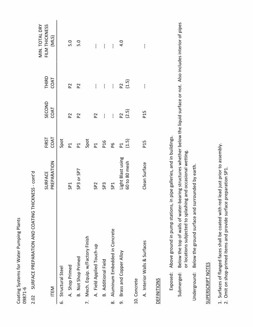
Coat
ing
Syst
ems f
or W
ater
Pum
ping
Pla
nts
0987
1-6
2.02
SU
RFAC
E PR
EPAR
ATIO
N A
ND
COAT
ING
THIC
KNES
S - c
ont’d
IT
EM
SURF
ACE
PREP
ARAT
ION
FI
RST
COAT
SE
CON
D CO
AT
THIR
D CO
AT
MIN
. TO
TAL
DRY
FILM
THI
CKN
ESS
(MLS
)
6.
Stru
ctur
al S
teel
Spot
A.
Sho
p Pr
imed
SP
1 P1
P2
P2
5.
0
B.
Not
Sho
p Pr
imed
SP
3 or
SP7
P1
P2
P2
5.
0
7.
Mec
h. E
quip
. w/F
acto
ry F
inish
Spot
A.
Fie
ld A
pplie
d To
uch-
up
SP2
P1
P2
---
---
B.
Add
ition
al F
ield
SP
3 P1
6 ---
---
---
8.
Alum
inum
Em
bedd
ed in
Con
cret
e SP
1 P6
---
---
---
9.
Bras
s and
Cop
per A
lloy
Ligh
t Bla
st u
sing
60 to
80
mes
h P1
(1
.5)
P2
(2.5
) P2
(1
.5)
4.0
10. C
oncr
ete
A.
Int
erio
r Wal
ls &
Sur
face
s Cl
ean
Surf
ace
P15
P15
---
---
DEFI
NIT
ION
S
Expo
sed:
Ab
ove
grou
nd in
pum
p st
atio
ns, i
n pi
pe g
alle
ries,
and
in b
uild
ings
.
Subm
erge
d:
Belo
w th
e to
p of
wal
ls of
wat
er-b
earin
g st
ruct
ures
whe
ther
bel
ow th
e liq
uid
surf
ace
or n
ot.
Also
incl
udes
inte
rior o
f pip
es
or lo
catio
ns su
bjec
ted
to sp
lash
ing
and
occa
siona
l wet
ting.
Und
ergr
ound
: Be
low
the
grou
nd su
rfac
e an
d su
rrou
nded
by
eart
h.
SUPE
RSCR
IPT
NO
TES
1. S
urfa
ces o
f fla
nged
face
s sha
ll be
coa
ted
with
red
lead
just
prio
r to
asse
mbl
y.
2. O
mit
on sh
op-p
rimed
item
s and
pro
vide
surf
ace
prep
arat
ion
SP1.

Coating System for Water Pumping Plants Section 09871 – 7
2.03 COLOR AND PAINT SCHEDULE
ARCHITECTURAL SYSTEM DESIGNATION
DESCRIPTIVE MANUFACTURERS' COLOR CODING PAINT
PLANT BUILDINGS:
General surface Tan Rustoleum #865 (Dunes Tan)
Trim & Doors Dark Brown Rustoleum #977 (Chestnut Brown)
Walls (metal) Yellow-White Dunn-Edwards #CH-60B (Parchment)
* * * * * * * * * * * * * * * * * * * * * * * * * * * * * * * * * * * * * * * *
PROCESS SYSTEM DESIGNATION
DESCRIPTIVE MANUFACTURERS' COLOR CODING PAINT
All exposed piping not within building or structures
Desert Tan Koppers No. 111 Glamourtex 501
2.04 IDENTIFICATION OF PIPING
A. Piping Systems. Identification of piping systems shall conform to the requirements of ANSI A13.1, "Scheme for the Identification of Piping System", unless otherwise specified herein.
B. Color Identification. All exposed and/or unburied pipe, including tubing, galvanized pipe, polyvinyl chloride pipe, fiberglass reinforced pipe, and stainless steel pipe, shall be identified by color to show its use function. Color bands of an approved taped type may be used on PVC, FRP, and stainless steel pipe and all other pipe not readily susceptible to painted finish. Markers shall be adhesive type with extra strength and suitable for continuous duty at 250° F. All markers shall have a protective silicone film.
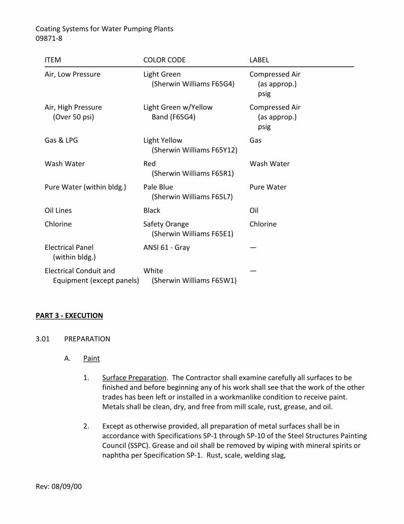
Rev: 08/09/00
Coating Systems for Water Pumping Plants 09871-8
ITEM COLOR CODE LABEL
Air, Low Pressure Light Green (Sherwin Williams F65G4)
Compressed Air (as approp.) psig
Air, High Pressure (Over 50 psi)
Light Green w/Yellow Band (F65G4)
Compressed Air (as approp.) psig
Gas & LPG Light Yellow (Sherwin Williams F65Y12)
Gas
Wash Water Red (Sherwin Williams F65R1)
Wash Water
Pure Water (within bldg.) Pale Blue (Sherwin Williams F65L7)
Pure Water
Oil Lines Black Oil
Chlorine Safety Orange (Sherwin Williams F65E1)
Chlorine
Electrical Panel (within bldg.)
ANSI 61 - Gray —
Electrical Conduit and Equipment (except panels)
White (Sherwin Williams F65W1)
—
PART 3 - EXECUTION
3.01 PREPARATION
A. Paint 1. Surface Preparation. The Contractor shall examine carefully all surfaces to be
finished and before beginning any of his work shall see that the work of the other trades has been left or installed in a workmanlike condition to receive paint. Metals shall be clean, dry, and free from mill scale, rust, grease, and oil.
2. Except as otherwise provided, all preparation of metal surfaces shall be in accordance with Specifications SP-1 through SP-10 of the Steel Structures Painting Council (SSPC). Grease and oil shall be removed by wiping with mineral spirits or naphtha per Specification SP-1. Rust, scale, welding slag,

Coating System for Water Pumping Plants Section 09871 – 9
and spatter shall be removed by wiping with mineral spirits or naphtha per Specification SP-1. Rust, scale, welding slag, and spatter shall be removed and the surface prepared by hand tool cleaning, power tool cleaning, or blast cleaning in accordance with the appropriate Specification SP-2 through SP-10.
3. Mixing. Paint containers shall be opened only when required for use. Paint shall be mixed only in designated rooms or spaces in the presence of the Engineer. Paint shall be thoroughly stirred or agitated to uniformly smooth consistency suitable for proper application. In all cases, paint shall be prepared and handled in a manner to prevent deterioration and inclusion of foreign matter.
B. Epoxy Coatings. All oil and grease shall be removed from the metal by caustic degreasing or steam cleaning. The surface shall be sandblasted to near-white metal in accordance with SSPC-SP10. In order to obtain maximum adhesion of epoxy coating, the grit used for blasting shall be coarse enough to impact a tooth in the metal equal to 25% of the thickness of the coating to be applied. The metal shall be cleaned, after sandblasting, with clean, dry compressed air. Use of rags to remove residual dust after sandblasting will not be permitted.
C. Ventilation. The Contractor shall not permit painting to begin in enclosed places until a forced draft ventilation system of sufficient air volume has been placed in operation.
3.02 APPLICATION OF PAINT The applicator of the paint shall have had past experience in applying the type or types of coatings and under similar conditions that he will be required to meet in this contract. The Contractor shall verify the paint applicator's qualifications before subcontracting the work to him. No painting shall be done under dusty conditions, during or immediately after a rain, during rainy weather, or when the temperature is less than 50° F. Except that prime coats shall be applied by brush and well worked into the surface, paint may be applied by brush, roller, trowel, or spray, unless the manufacturer's recommendations or these specifications call for some particular type of application. Where spray application is used, each coat of paint shall be applied to a thickness equivalent to a brush coat application at a coverage not greater than that specified by the manufacturer for a brush coat application. All work shall be done in a workmanlike manner, leaving the finished surfaces free from drops, waves, holidays, laps, or brush marks. Drop cloths and other coverings shall be so placed at all times as to protect floors and other surfaces from spatter and droppings. Hardware, plates, lighting fixtures, nameplates, and similar articles which are not to be painted shall be masked off or removed completely. After completion of painting, any spatter or droppings shall be removed.
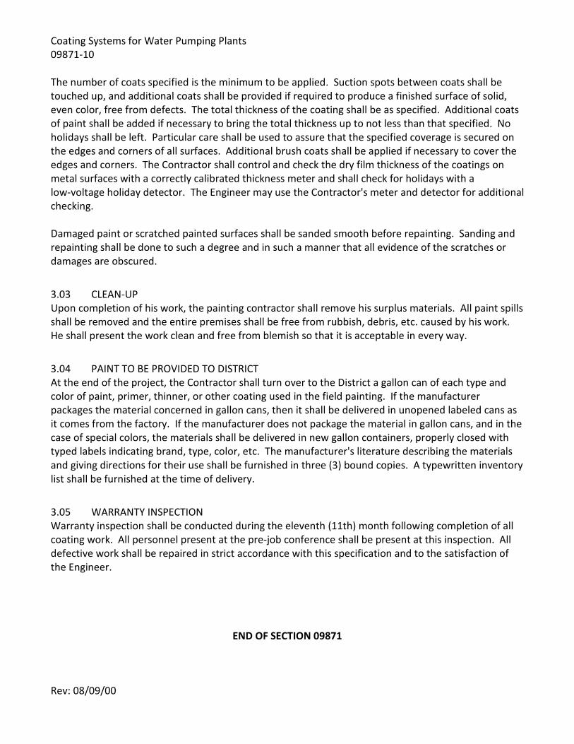
Rev: 08/09/00
Coating Systems for Water Pumping Plants 09871-10 The number of coats specified is the minimum to be applied. Suction spots between coats shall be touched up, and additional coats shall be provided if required to produce a finished surface of solid, even color, free from defects. The total thickness of the coating shall be as specified. Additional coats of paint shall be added if necessary to bring the total thickness up to not less than that specified. No holidays shall be left. Particular care shall be used to assure that the specified coverage is secured on the edges and corners of all surfaces. Additional brush coats shall be applied if necessary to cover the edges and corners. The Contractor shall control and check the dry film thickness of the coatings on metal surfaces with a correctly calibrated thickness meter and shall check for holidays with a low-voltage holiday detector. The Engineer may use the Contractor's meter and detector for additional checking. Damaged paint or scratched painted surfaces shall be sanded smooth before repainting. Sanding and repainting shall be done to such a degree and in such a manner that all evidence of the scratches or damages are obscured.
3.03 CLEAN-UP Upon completion of his work, the painting contractor shall remove his surplus materials. All paint spills shall be removed and the entire premises shall be free from rubbish, debris, etc. caused by his work. He shall present the work clean and free from blemish so that it is acceptable in every way.
3.04 PAINT TO BE PROVIDED TO DISTRICT At the end of the project, the Contractor shall turn over to the District a gallon can of each type and color of paint, primer, thinner, or other coating used in the field painting. If the manufacturer packages the material concerned in gallon cans, then it shall be delivered in unopened labeled cans as it comes from the factory. If the manufacturer does not package the material in gallon cans, and in the case of special colors, the materials shall be delivered in new gallon containers, properly closed with typed labels indicating brand, type, color, etc. The manufacturer's literature describing the materials and giving directions for their use shall be furnished in three (3) bound copies. A typewritten inventory list shall be furnished at the time of delivery.
3.05 WARRANTY INSPECTION Warranty inspection shall be conducted during the eleventh (11th) month following completion of all coating work. All personnel present at the pre-job conference shall be present at this inspection. All defective work shall be repaired in strict accordance with this specification and to the satisfaction of the Engineer.
END OF SECTION 09871

Rev: 09/85
SPECIFICATIONS - DETAILED PROVISIONS Section 09940 - Epoxy Coating
C O N T E N T S
PART 1 - GENERAL ............................................................................................................................. 1
1.01 REQUIREMENT .......................................................................................................................... 1 PART 2 - PRODUCTS .......................................................................................................................... 1
2.01 MATERIAL .................................................................................................................................. 1 PART 3 - EXECUTION ......................................................................................................................... 1
3.01 SURFACE PREPARATION ............................................................................................................ 1 3.02 APPLICATION ............................................................................................................................. 1 3.03 THICKNESS OF COATING ........................................................................................................... 1 3.04 INSPECTION ............................................................................................................................... 1 3.05 FIELD REPAIRS ........................................................................................................................... 1

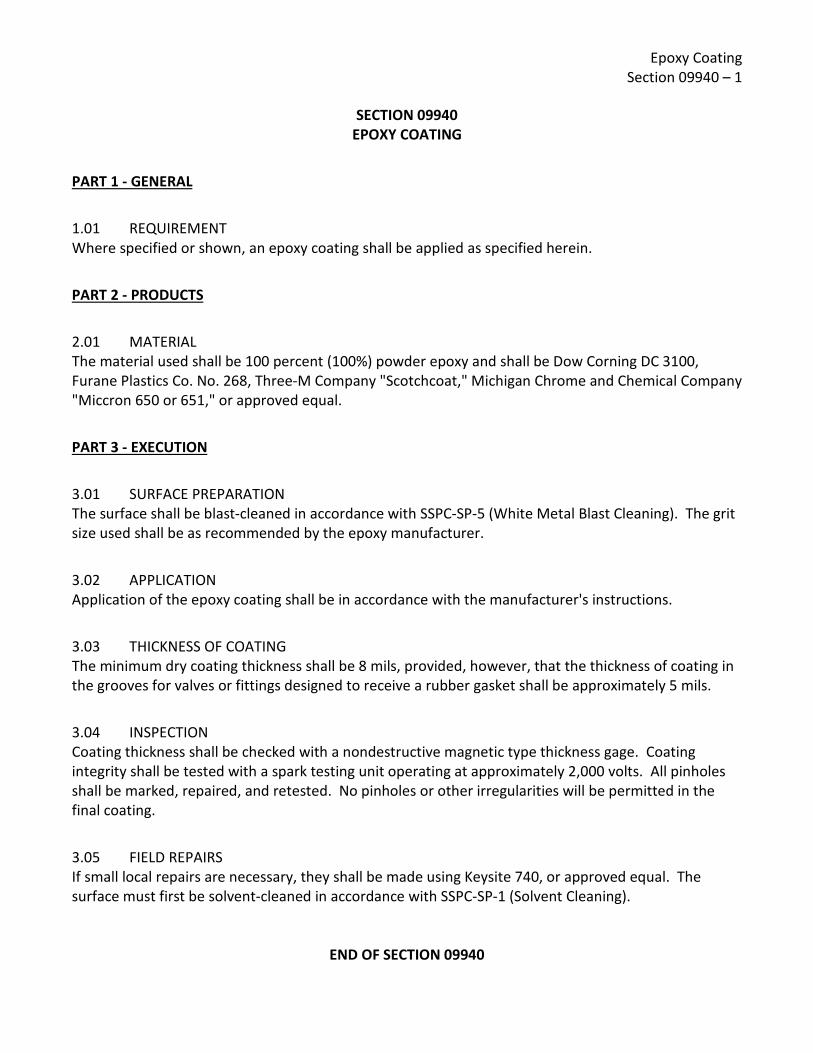
Epoxy Coating Section 09940 – 1
SECTION 09940
EPOXY COATING
PART 1 - GENERAL
1.01 REQUIREMENT Where specified or shown, an epoxy coating shall be applied as specified herein.
PART 2 - PRODUCTS
2.01 MATERIAL The material used shall be 100 percent (100%) powder epoxy and shall be Dow Corning DC 3100, Furane Plastics Co. No. 268, Three-M Company "Scotchcoat," Michigan Chrome and Chemical Company "Miccron 650 or 651," or approved equal.
PART 3 - EXECUTION
3.01 SURFACE PREPARATION The surface shall be blast-cleaned in accordance with SSPC-SP-5 (White Metal Blast Cleaning). The grit size used shall be as recommended by the epoxy manufacturer.
3.02 APPLICATION Application of the epoxy coating shall be in accordance with the manufacturer's instructions.
3.03 THICKNESS OF COATING The minimum dry coating thickness shall be 8 mils, provided, however, that the thickness of coating in the grooves for valves or fittings designed to receive a rubber gasket shall be approximately 5 mils.
3.04 INSPECTION Coating thickness shall be checked with a nondestructive magnetic type thickness gage. Coating integrity shall be tested with a spark testing unit operating at approximately 2,000 volts. All pinholes shall be marked, repaired, and retested. No pinholes or other irregularities will be permitted in the final coating.
3.05 FIELD REPAIRS If small local repairs are necessary, they shall be made using Keysite 740, or approved equal. The surface must first be solvent-cleaned in accordance with SSPC-SP-1 (Solvent Cleaning).
END OF SECTION 09940

Epoxy Coating Section 09940 – 2
[PAGE LEFT INTENTIONALLY BLANK]

Rev: 05/13/21
SPECIFICATIONS - DETAILED PROVISIONS Section 11005 - General Mechanical and Equipment Provisions
C O N T E N T S
PART 1 - GENERAL ............................................................................................................................. 1
1.01 DESCRIPTION ............................................................................................................................. 1 1.02 MANUFACTURER'S EXPERIENCE ............................................................................................... 1 1.03 FACTORY INSPECTION ............................................................................................................... 1 1.04 STANDARD OF QUALITY ............................................................................................................ 1 1.05 ADAPTATION OF EQUIPMENT .................................................................................................. 1 1.06 GUARANTEES AND WARRANTIES ............................................................................................. 2 1.07 SUBMITTALS .............................................................................................................................. 2 1.08 PRODUCT DELIVERY, STORAGE AND HANDLING ...................................................................... 4 1.09 JOB CONDITIONS ....................................................................................................................... 4 1.10 EQUIPMENT .............................................................................................................................. 4
PART 2 - PRODUCTS .......................................................................................................................... 5 2.01 MATERIALS AND WORKMANSHIP............................................................................................. 5 2.02 LUBRICATION ............................................................................................................................ 5 2.03 STRUCTURAL STEEL FABRICATIONS .......................................................................................... 6 2.04 EQUIPMENT BASES AND BEDPLATES ........................................................................................ 6 2.05 ANCHORS AND SLEEVES ............................................................................................................ 6 2.06 SAFETY GUARDS ........................................................................................................................ 6 2.07 DRIVE UNITS .............................................................................................................................. 6 2.08 GEARS ........................................................................................................................................ 7 2.09 ELECTRICAL MOTORS FOR MECHANICAL EQUIPMENT ............................................................ 7 2.10 CONTACTS ................................................................................................................................. 8 2.11 GAUGES ..................................................................................................................................... 8 2.12 NAMEPLATES AND DATA PLATES.............................................................................................. 8 2.13 PAINTING .................................................................................................................................. 8
PART 3 - EXECUTION ......................................................................................................................... 9 3.01 COORDINATION ........................................................................................................................ 9 3.02 INSPECTION ............................................................................................................................... 9 3.03 PREPARATION ........................................................................................................................... 9 3.04 MANUFACTURERS' SUPERVISION AND INSTALLATION CHECK ............................................... 10 3.05 INSTALLATION ......................................................................................................................... 10 3.06 FIELD QUALITY CONTROL ........................................................................................................ 10 3.07 CONSOLIDATION OF DEMONSTRATION, TESTING, AND INSTRUCTION REQUIREMENTS ...... 14 3.08 SOUND LEVEL TESTING AND WORKER PROTECTION ............................................................. 15 3.09 IN-SERVICE CHECKS ................................................................................................................. 15 3.10 PUMPS ..................................................................................................................................... 15 3.11 EARTHQUAKE DESIGN AND RESTRAINT .................................................................................. 17

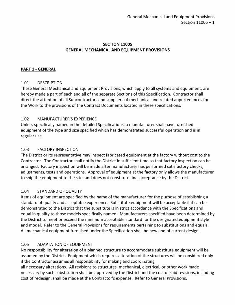
General Mechanical and Equipment Provisions Section 11005 – 1
SECTION 11005
GENERAL MECHANICAL AND EQUIPMENT PROVISIONS
PART 1 - GENERAL
1.01 DESCRIPTION These General Mechanical and Equipment Provisions, which apply to all systems and equipment, are hereby made a part of each and all of the separate Sections of this Specification. Contractor shall direct the attention of all Subcontractors and suppliers of mechanical and related appurtenances for the Work to the provisions of the Contract Documents located in these specifications.
1.02 MANUFACTURER'S EXPERIENCE Unless specifically named in the detailed Specifications, a manufacturer shall have furnished equipment of the type and size specified which has demonstrated successful operation and is in regular use.
1.03 FACTORY INSPECTION The District or its representative may inspect fabricated equipment at the factory without cost to the Contractor. The Contractor shall notify the District in sufficient time so that factory inspection can be arranged. Factory inspection will be made after manufacturer has performed satisfactory checks, adjustments, tests and operations. Approval of equipment at the factory only allows the manufacturer to ship the equipment to the site, and does not constitute final acceptance by the District.
1.04 STANDARD OF QUALITY Items of equipment are specified by the name of the manufacturer for the purpose of establishing a standard of quality and acceptable experience. Substitute equipment will be acceptable if it can be demonstrated to the District that the substitute is in strict accordance with the Specifications and equal in quality to those models specifically named. Manufacturers specified have been determined by the District to meet or exceed the minimum acceptable standard for the designated equipment style and model. Refer to the General Provisions for requirements pertaining to substitutions and equals. All mechanical equipment furnished under the Specification shall be new and of current design.
1.05 ADAPTATION OF EQUIPMENT No responsibility for alteration of a planned structure to accommodate substitute equipment will be assumed by the District. Equipment which requires alteration of the structures will be considered only if the Contractor assumes all responsibility for making and coordinating all necessary alterations. All revisions to structures, mechanical, electrical, or other work made necessary by such substitution shall be approved by the District and the cost of said revisions, including cost of redesign, shall be made at the Contractor's expense. Refer to General Provisions.

General Mechanical and Equipment Provisions Section 11005 – 2
A. Horsepower Ratings. Horsepower ratings specified and/or shown for the proposed equipment are in accordance with the best information available to the District. In the event any equipment item proposed by the Contractor should require motors with larger horsepower rating than indicated on Electrical Drawings, it shall be the Contractor's responsibility to provide the proper control equipment, required modifications to motor control centers, starting equipment, feeder and branch circuit, and accessories as required to make the installation comply with the electrical code and to prevent excessive voltage drop without added cost to the District.
B. Equipment. Where equipment to be furnished is installed in an existing enclosure or adjacent to existing equipment, the Contractor shall field check the dimensions of existing equipment, location of conduits, etc., and shall familiarize himself with all existing conditions and difficulties to be encountered in performing such work.
1.06 GUARANTEES AND WARRANTIES The Contractor shall guarantee all equipment in accordance with the Conditions of the Contract. In addition to the general guarantee requirements, equipment guarantee shall cover (1) faulty or inadequate design; (2) improper assembly or erection; (3) defective workmanship or materials; and (4) leakage, breakage, or other failure. For equipment bearing a manufacturer's warranty in excess of one (1) year, furnish a copy of the warranty to District with District named as beneficiary. The period of all guarantees shall be initiated from the date of the District written acceptance of the Work.
1.07 SUBMITTALS Refer to Section F Labor and Construction, F-29, Paragraph D. "Submittals" and to specific Divisions and Sections for additional submittal requirements.
A. Shop Drawings. Shop drawings shall be submitted to the District in complete sets indexed by Specification paragraph and Drawing number describing the various equipment items or systems. Unless otherwise specified or directed, submit shop drawings for all mechanical equipment specified herein.
B. Earthquake Design Data. Submit with the shop drawings complete calculations or test results, details of constructions, and method of attachment for all manufactured products showing compliance with Paragraph 3.11, "Earthquake Design and Restraint." The calculations and details shall be signed by a Professional Engineer who has demonstrated proficiency in Structural Engineering or Civil Engineering and is registered in the State of California.
C. Instruction Manuals. Prepare and submit instruction manuals covering all mechanical equipment and machinery specified herein.

General Mechanical and Equipment Provisions Section 11005 – 3
D. Manufacturers' Certified Reports. Each equipment manufacturer, or his authorized representative, shall submit a notarized written report with respect to his equipment certifying that (1) the equipment has been properly installed and lubricated under his supervision, (2) the equipment is in accurate alignment, (3) he was present when the equipment was placed in operation, (4) he has checked, inspected, and adjusted the equipment as necessary, (5) the equipment is free from any undue stress imposed by connecting piping or anchor bolts, (6) has been satisfactorily operated under full load conditions, (7) he has inspected his equipment during the operational demonstrations and system validation tests to the extent specified, and (8) the equipment is fully covered under the terms of the guarantee.
E. Submittals For Operational Demonstration and System Validation Tests 1. Operation Demonstration. When the Contractor's application for a progress
payment equals or exceeds 75% of the Contract value for the first time, submit a detailed and comprehensive procedure plan for performance of each operation demonstration required. Identical equipment items may be covered under one plan. Include an estimated date and duration for each procedure and personnel required.
2. System Validation Tests. When the Contractor's application for a progress payment equals or exceeds 75% of the Contract value for the first time, submit a detailed and comprehensive procedure plan for performance of each separate validation test and for each validation test that covers two or more systems. Each procedure plan shall describe and itemize the involved system, including associated electrical equipment and instrumentation and control systems, and shall include evidence of an organized step-by-step procedure properly coordinating the efforts of various trades and manufacturers' representatives involved and of the operation of the facilities. Procedures shall include an estimated duration and date for each procedure and the personnel required.
3. Procedure Plan Information. In addition to the information specified above, each procedure plan shall include the following information as applicable. a) Description of temporary procedure facilities, including Drawings and
sketches as required to fully illustrate the facilities.
b) List of test materials and estimated quantities.
c) List of instruments, measuring and recording devices, and other test equipment, whether a part of the plant or furnished separately for temporary use.
d) Names of supervising and inspecting manufacturers.

General Mechanical and Equipment Provisions Section 11005 – 4
e) Complete listing of all functional parameters to be observed and recorded.
f) Recording intervals.
4. Records Materials. Submit samples of the forms, charts, and other materials to be
used in recording demonstration and validation test results.
5. Results. Within 10 days after completion of each procedure plan submit copies of all recordings and results of all operational demonstrations and system validation tests.
F. Electric Motors. Conform with applicable requirements specified in Sections 16150 and 16151 herein.
1.08 PRODUCT DELIVERY, STORAGE AND HANDLING Box, crate, or otherwise enclose and protect equipment during shipment, handling, storage, and following installation until final acceptance of the project. Keep equipment dry and covered from exposure to weather. Store pumps, motor, electrical equipment, and equipment having anti-friction or sleeve bearings in weathertight storage facilities. Lift large equipment items only at the points designated by manufacturer.
A. Factory Painted Surfaces. Protect against impact, abrasion, discoloration, and other damage. Repair damage as directed and approved (Refer to Section 09871).
B. Electrical Equipment. Maintain electrical equipment, controls, and keep insulation dry at all times. Keep heaters in equipment connected and operating until equipment is placed in operation.
1.09 JOB CONDITIONS Drawings are diagrammatic and show the intended arrangement of principle apparatus, piping, and appurtenances. Conform to Drawings as closely as possible and exercise care to secure approved headroom and space conditions, neat arrangement of piping, valves, hangers, and like items, and to overcome structural interferences. Verify dimensions and conditions at the place of installation, and install materials and equipment in the available spaces. Submit written details and reasons for proposed deviations from Drawings and Specifications, and do not deviate therefrom unless authorized by Field Order or Change Order. If approved changes require alteration of structures or related work, make such alterations as approved in advance by District at no additional cost to District.
1.10 EQUIPMENT All equipment furnished shall be complete, ready for installation and operation. Al bolts, nuts, washers, mounting plates, bed plates, bases, anchor bolts and other miscellaneous items necessary to form a complete, installed, operational system shall be furnished whether specifically specified or not.

General Mechanical and Equipment Provisions Section 11005 – 5
PART 2 - PRODUCTS
2.01 MATERIALS AND WORKMANSHIP All equipment furnished shall be new and guaranteed free from defects in materials, design, and workmanship. It shall be the manufacturer's responsibility to ascertain the conditions and service under which the equipment will operate and to warrant that operation under these conditions shall be successful. All parts of the equipment shall be amply proportioned for all stresses that may occur during fabrication, erection, and intermittent or continuous operation. All equipment shall be designed, fabricated, and assembled in accordance with the best modern engineering and shop practice. Individual parts shall be manufactured to standard sizes and gauges so that repair parts, furnished at any time, can be installed in the field. Like parts of duplicate units shall be interchangeable. Equipment shall not have been in service at any time prior to delivery, except as required by tests. Materials shall be suitable for service conditions. Iron castings shall be tough, close-grained gray iron free from blowholes, flaws, or excessive shrinkage and shall conform to ASTM A48. Except where otherwise specified, structural and miscellaneous fabricated steel used in items of equipment shall conform to the Standards of the American Institute of Steel Construction. All structural members shall be considered as subject to shock or vibratory loads. Unless otherwise specified, all steel which will be submerged, all or in part, during normal operation of the equipment shall have a minimum nominal thickness of 1/4-inch. Provide equipment and materials suitable for the service conditions and meeting standard specifications such as ANSI, ASME, AWWA, ASTM, NEMB, UBC, and UL. The location of the fabricator and his shop schedule shall be furnished to the District prior to the beginning of fabrication so that the District can schedule shop inspection.
2.02 LUBRICATION
A. Lubricants. Provide lubricants of types recommended by equipment manufacturers, quantities sufficient for consumption prior to completion, testing, and final acceptance.
B. Lubrication Systems. Lubrication of equipment shall ensure constant presence of lubricant on all wearing surfaces. Lubricant fill and drain openings shall be readily accessible. Easy means for checking the lubricant level shall be provided. Prior to testing and/or operation, the equipment shall receive the prescribed amount and type of lubricant as required by the equipment manufacturer. Equipment lubrication systems shall be systems that require attention during start up of shut down, and shall not waste lubricants.

General Mechanical and Equipment Provisions Section 11005 – 6 2.03 STRUCTURAL STEEL FABRICATIONS Conform to "Code of Standard Practice for Steel Buildings and Bridges" and "Specification for the Design, Fabrication and Erection of Structural Steel for Buildings" of the AISC unless otherwise indicated or specified. Design all fabrications for dynamic and vibratory loadings. Use structural steel shapes conforming to ASTM A36, A440, A500, A501, A570, A618, or equal, as applicable. Conform welding to AWS D1.1 Structural Welding Code. Galvanized specified items in accordance with ASTM A123, A153, or A386 as applicable; use galvanized bolts and fasteners with galvanized assemblies.
2.04 EQUIPMENT BASES AND BEDPLATES Mount equipment assemblies on a single heavy cast iron or welded steel bedplate unless otherwise shown or specified. Provide bases and bedplates with machined support pads, tapered dowels for alignment or mating of adjacent items, adequate openings to facilitate grouting, and openings for electrical conduits. Continuously weld seams and contact edges between steel plates and shapes, and grind welds smooth. Do not support machinery or piping on bedplates other than that which is factory installed. Provide jacking screws in equipment bases and bedplates to aid in leveling prior to grouting. Provide plates of minimum thickness of 1/4-inch. Pump bedplates shall include a drip lip and provisions for directing leakage to a single disposal point.
2.05 ANCHORS AND SLEEVES Each equipment manufacturer shall furnish the required anchor bolts, nuts, washers, and sleeves of adequate design for securing bases and bedplates to concrete bases. Provide sleeves of at least 1-1/2 times anchor bolt diameter. Anchor bolts shall be Type 316 stainless steel. Provide anchor bolts of length to allow for 1-1/2 inch of grout under baseplates and adequate anchorage into structural concrete unless otherwise shown or specified. Conform to designs for attachments to resist seismic forces, as applicable.
2.06 SAFETY GUARDS Cover belt or chain drives, fan blades, couplings, exposed shafts and other moving or rotating parts on all sides with safety guards conforming to all Federal, state, and local codes and regulations pertaining; conform to the most restrictive requirements. Safety guards shall be free of all sharp edges and corners. Use corrosion-resistant materials at least equivalent to hot-dip galvanized steel. Safety guards shall be fabricated from 16USS gauge, or heavier, galvanized or aluminum-clad steel or 1/2-inch mesh galvanized expanded metal. Design guards for easy installation and removal. Provide necessary supports, accessories, and fasteners, of hot-dip galvanized steel or stainless steel. Design guards in outdoor locations to prevent entrance of rain and dripping water.
2.07 DRIVE UNITS Provide drive units designed with a AGMA rating and service factor suitable for 24 hour continuous duty service under operating load, constructed to preclude oil leakage around shafts. Drive unit housings shall be constructed of high grade cast iron, welded steel, or other suitable material. Thermal rating of each unit shall exceed the design load or proper cooling devices shall be provided. All drives shall be designed specifically for the service conditions under which they are to operate.
General Mechanical and Equipment Provisions Section 11005 – 7
A. Motor Ratings. Provide drive motors having nameplate horsepower rating at least equal
to 110 percent of the theoretical brake horsepower required to drive equipment under full load for conditions specified, including all losses in speed reducers and power transmission. Refer also to Section 16150.
B. V-Belt Drives. Equip each V-belt with a sliding base or other suitable tension adjustment. Where motors are mounted above the driven machine on a pedestal, the belt tensioning shall be accomplished by four studs which are double nutted to the motor plate to raise and lower the motor plate. Hinges with jacking screw to tension the belts shall not be used. Provide drives having a service factor of at least 1.6 at maximum torque using nameplate rating of driving motor.
2.08 GEARS Provide oil-lubricated totally-enclosed gear reducers and increasers.
A. Service Ratings. Each gear shall have a nameplate service horsepower rating equal to the nameplate rating of the driving motor. Each gear shall have mechanical and thermal capacity equal to, or greater than an equivalent horsepower determined by multiplying the service horsepower rating by the specified service factor recommended by AGMA for heavy duty service, except each set of worm gears shall have a minimum service factor of 1.50.
B. Thermal Rating. Obtain thermal rating for the equivalent horsepower without auxiliary cooling equipment such as heat exchangers. Design units to operate continuously for the conditions specified in a location where ambient temperatures vary from 30° to 130° F. If a cooling coil is required, provide minimum 1-inch diameter tubing and a 1-inch solenoid supply water valve with the gear.
C. Bearings. Provide anti-friction bearings throughout, designed to give 20,000 hours B100 life for the specified horsepower in continuous operation, of proportions, mounting and adjustment consistent with acceptable modern practices for applied radial and thrust loads at speeds involved. Provide thrust bearing rates at 1-1/2 times the maximum thrust loadings involved.
D. Gear Nameplates. Equip each gear with an AGMA nameplate which shows service horsepower, actual service factor for actual mechanical or thermal rating as applicable, and AGMA gear Class I rating.
2.09 ELECTRICAL MOTORS FOR MECHANICAL EQUIPMENT Conform with applicable requirements of Division 16.

General Mechanical and Equipment Provisions Section 11005 – 8 2.10 CONTACTS For interlock or failure indicating contacts specified to be supplied as part of equipment, provide SPDT switches rated for 120 VAC, 60 Hz at 5 amperes resistive or 3 amperes inductive loading, terminated at screw-type barrier strips in a NEMA 4 enclosure, unless otherwise shown or specified.
2.11 GAUGES Gauges shall be installed in the suction (where applicable) and discharge piping of each pump and blower. The gauges shall be 4-inch diameter, liquid filled and shall include a petcock (Corp stop) between the pump/blower piping and the gauge. For solids bearing or corrosive fluids, a diaphragm gauge isolator shall be provided. Suction gauges shall be of the compound type and shall have a range as shown on the Drawings. Discharge gauge ranges shall be a standard commercially available range as shown on the drawings.
2.12 NAMEPLATES AND DATA PLATES Provide Type 302, 304, or 316 stainless steel nameplates of ample size with embossed or preprinted lettering, fastened to the equipment in a prominent place with corrosion-resisting pins. On nameplates, display manufacturer, serial number, date of manufacture, model number and essential operating characteristics. Inscribe data plates with specific or directed information.
2.13 PAINTING Conform to applicable requirements of Section 09871 "Coating System for Water Pumping Plants" and following requirements unless modified or superceded under other Sections.
A. Factory Painting. On mechanical equipment, drives, starters, control panels and other similar self-contained or enclosed components, apply a factory primer and high-quality oil-resistant baked industrial enamel finish. Paint or otherwise protect surfaces that are inaccessible after assembly by a method which provides protection for the life of the equipment.
B. Shop Priming. Apply one or more shop coats of metal primer on surfaces to be finish painted at the site to protect surfaces until finished. Use primers specified for the required paint system in Section 09871.
C. Rust Preventive. Coat machined, polished, or other ferrous surfaces, and non-ferrous surfaces, which are not to be painted, with rust preventive compound, as manufactured by Sanchem, Houghton, Rust-Oleum, or approved equal.
General Mechanical and Equipment Provisions Section 11005 – 9
PART 3 - EXECUTION
3.01 COORDINATION The Drawings show in a diagrammatic form the arrangements desired for the principle apparatus, piping, and similar appurtenances, and shall be followed as closely as possible. Proper judgment must be exercised in carrying out the work to secure the best possible headroom and space conditions throughout, to secure neat arrangement of piping, valves, fixtures, hangers, and similar appurtenances, and to overcome local difficulties and interferences of structural conditions wherever encountered. The Contractor shall take all measurements for his work at the installation sites, verify all subcontractor drawings and be responsible for the proper installation, within the available space for the apparatus specified and shown on the Drawings, and must secure the approval of the District for any variations before making any changes. Refer to pertinent Sections for items of equipment to be assembled of several components under the unit responsibility of one manufacturer. To coordinate this requirement, the Contractor shall monitor and verify the unit responsibility processes and submit the following information to the District in writing on a monthly basis:
A. Shipment dates of the various components to the unit responsibility manufacturers.
B. Scheduled dates of factory tests by unit responsibility manufacturers.
C. Scheduled shipments dates to site of unit responsibility items.
D. Scheduled arrival date, installation date and start-up date.
3.02 INSPECTION Inspect each item of equipment for damage, defects, completeness, and correct operation before installing. Inspect previously installed related work and verify that it is ready for installation of the equipment.
3.03 PREPARATION Prior to installing equipment, ensure that installation areas are clean and that concrete or masonry operations are completed. Maintain the areas in a broom-clean condition during installation operations. Clean, condition, and service equipment in accordance with the reviewed Instruction Manuals and requirements in other Sections of these Specifications before installing.
General Mechanical and Equipment Provisions Section 11005 – 10 3.04 MANUFACTURERS' SUPERVISION AND INSTALLATION CHECK Each equipment manufacturer shall furnish the services of an authorized representative specially trained and experienced in the installation of his equipment to (1) supervise the equipment installation in accordance with the reviewed Instruction Manual, (2) be present when the equipment is first put into operation, (3) inspect, check, adjust as necessary, and approve the installation, (4) repeat the inspection, checking, and adjusting until all trouble or defects are corrected and the equipment installation and operation are acceptable, (5) witness and supervise operational demonstrations and system validation tests to the extent specified, and (6) prepare and submit the specified Manufacturers' Certified Report. Include all costs for representatives service in the Contract Price.
3.05 INSTALLATION
A. Structural Fabrications. Conform to the AISC Code and Specification references in Article "Structural Steel Fabrications."
B. Equipment. Conform to reviewed Instruction Manuals. Employ skilled craftsmen experienced in installation of the types of equipment specified. Use specialized tools and equipment, such as precision machinist levels, dial indicators, gauges, and micrometers, as applicable. Produce acceptable installations free of vibration or other defects.
C. Anchor Bolts. Deliver bolts with templates or setting drawings and verify that bolts are correctly located before structural concrete is placed.
D. Base and Bedplate Grouting. Do not place grout until initial fitting and alignment of connected piping is completed. Level and align equipment on the concrete foundations, then entirely fill the space under base or bedplates with grout. Bevel exposed grout at 45 degree angle, except round exposed grout at horizontal surfaces for drainage. Trowel or point exposed grout to a smooth dense finish and damp cure with burlap for three days. When grout is fully hardened, remove jacking screws and tighten nuts on anchor bolts. Check the installation for alignment and level, and perform approved corrective work as required to conform to the tolerances given in the applicable Instruction Manual.
3.06 FIELD QUALITY CONTROL
A. General. All costs for performing operational demonstrations and system validation tests shall be included in the Contract Price, and no extra payment will be made to the Contractor due to overtime, weekend, or holiday labor costs required to perform and complete the demonstrations and validation tests. Requirements specified in this Article are in addition to the demonstration and test requirements specified under other Sections of these Specifications.
General Mechanical and Equipment Provisions Section 11005 – 11
1. Operational Demonstration and Systems Validation Testing shall be performed by
the Contractor in accordance with the approved procedure plans to demonstrate to the District's satisfaction that: a) All components of the process systems defined herein, the complete
systems, and the new plant systems are fully completed and operable.
b) All units, components, systems, and the entire plant systems operate with the efficiency, repeatability, and accuracy indicated and specified.
c) All components, systems, and the entire plant conform to the Contract Documents and the reviewed shop drawings, samples, construction manuals, materials lists, and other reviewed submittals.
2. Scope of Demonstrations and Validation Testing. Operational demonstrations and
system validation tests are required for all work, equipment, and systems specified in these Specifications including all associated and related electrical systems and control devices. a) Equipment and work to be operationally demonstrated are defined as
individual equipment items such as pumps, compressors, mixers, sludge collecting mechanisms, belt press and like equipment items. Demonstrations shall be performed simultaneously on groups of identical equipment items and groups of items supplied by one manufacturer to the extent feasible.
b) Systems to be validation tested are defined as complete systems that perform a discrete process function of the plant such as chemical systems, sludge collection system, sludge dewatering system, and similar systems. Each system shall include associated structures, tanks, piping, utilities, instrumentation and controls, and like related items. Two or more separate systems shall be validation tested simultaneously when necessary to validate an entire discrete plant function.
3. Prerequisite Conditions. Operational demonstrations and validation testing shall
not commence for any equipment item or system until all related structures, piping, electrical, instrumentation, control, and like work has been installed, tested, and connected in compliance with the pertaining requirements specified elsewhere in the Specifications.

General Mechanical and Equipment Provisions Section 11005 – 12
4. Demonstration and Testing Materials. Furnish materials, natural gas and/or electrical power for operation demonstrations and validation tests. Use fresh water to fill tanks, wells, piping, and systems that contain water or wastewater in normal operation. Use the specified chemicals or chemical systems but do not exceed the "in service" concentrations. Furnish temporary facilities as required such as by-pass or re-circulation piping, diversions, storage, and similar facilities. Use procedures that conserve testing materials and avoid wastage, especially with respect to large quantities of fresh water and electrical power.
5. Inspection and Supervision by Manufacturers. Perform operational demonstrations and system validation testing under continuous inspection by the District. Technical representatives of the various equipment manufacturers shall be present at the start of the operational demonstrations, shall examine their equipment at least twice near the beginning and end of the validation tests, shall supervise the start up and adjustment procedures, and shall perform all other services necessary for the manufacturer's certified reports required herein.
6. Correction of Defects. Immediately correct all defects and malfunctions disclosed by demonstrations and validation tests using approved methods and new materials for repairs as required. Interruption time necessary for corrective work shall be added to the specified total demonstration and validation test periods.
7. Acceptance. Satisfactory completion and approval of required operational demonstrations and system validation testing is one of the conditions precedent to the District's acceptance of the work and does not constitute final acceptance. Refer to the Conditions of the Contract.
B. System Validation Tests. All equipment components of each system shall have
successfully completed the required operational demonstration before the system is validation tested. Perform validation testing in accordance with the approved procedure plan. 1. Test Period. Test each system, including standby systems, by continuous
operation in "in-service" condition for not less than 24 consecutive hours, with no interruptions except for normal maintenance or corrective work.
2. Testing Methods. Operate systems continuously 24 hours a day under constant inspection of trained operators. Cycle system operation from full load to light load and back to full load each 24 hours; cause variable speed equipment to cycle through the applicable speed range at a steady rate of change. Induce simulated alarm and distressed operating conditions, and test controls and protective devices for correct operation in adjusting system functions or causing system shutdown.

General Mechanical and Equipment Provisions Section 11005 – 13
3. Simulation of Conditions. Subject to Contractor's request and District's review in each case, the Contractor may simulate certain operating conditions relating to flow rates, water levels, and malfunctions. Permission for simulations will be granted only where it is unwise or impossible to obtain the conditions covered by the capability of ranges or equipment. The simulation methods shall reflect reasonable anticipated operating conditions.
4. Ranges for Testing.
a) Flow Metering Systems shall be tested at not less than 3 values
corresponding approximately to a minimum, average and maximum capacity, respectively.
b) Liquid Level Indicating Systems shall be tested at not less than 5 levels corresponding approximately to low, average, normal, maximum and high alarm levels, respectively. Low-low and high-high level alarms and system reaction shall also be tested where equipment or instruments are required to react to such conditions.
c) Remotely Controlled Valves shall demonstrate suitable operation both from local control and remote controls. As a minimum, these procedures shall include full-open and full-close positioning. Each test shall be repeated not less than 3 times for non-throttling and non-modulating valves. In addition to these minimum requirements, and subject to approval, all throttling valves and modulating valves shall be operated at not less than 3 intermediate positions and shall demonstrate the ability of each valve to hold the set position under operating conditions.
d) Variable Speed Equipment shall demonstrate accurate response to speed controlling devices and controls within the required operating ranges. Actual output shaft speeds of manually adjustable speed equipment shall be validated by measurement of shaft speeds versus speeds shown by equipment instruments.
5. Automatic Response of Equipment. Response of equipment to appropriate manual or automatic controls, or combinations of both automatic and manual controls, shall be demonstrated to be correct and accurate. Where applicable, all components shall be tested for both manual and automatic operation. Where a component performs more than one function, every function shall be validated. a) Pumping Equipment shall respond accurately and reliably to liquid level,
pressure and/or flow rate signals from appurtenant reservoirs, pipes or wet wells. Automatic alternation and back-up pump functions shall also be validated.

General Mechanical and Equipment Provisions Section 11005 – 14
b) Auxiliary Equipment Items such as automatic samplers, annunciators,
alarms, and like items shall respond accurately and reliably to every condition for which they are programmed, in the manner specified.
C. Recording of Data. Neat and comprehensive records of each operational demonstration
or validation test shall be maintained by the Contractor. Each portion of the demonstration or validation procedure shall be described with all components itemized. Records shall be prepared on forms in a step-by-step fashion paralleling the approved plans. Forms shall list for each condition: Step taken; Result anticipated; Result obtained; If incorrect, corrective action taken; and Retest result. The last two steps shall be repeated until all systems operate as required. 1. Recording Devices. Instruments, gauges, and other sensor and display devices
forming a part of the various systems shall be employed for data acquisition to the extent applicable. The Contractor shall furnish all other instruments, gauges, recorders, and test devices as required, types conforming to the approved procedure plans.
2. Information and Intervals. All applicable data such as, but not limited to, water and other liquid levels, pressures, head differentials, duration of runs, instrument readings, chemical feed rates, voltage settings, drive speeds, motor running currents, torque, voltage, GPM, pressures, clarity, residual chlorine and related information, as applicable, and in accordance with the approved procedure plans, shall be recorded at the start and finish of every operational demonstration and at maximum 8-hour intervals during system validation tests, unless shorter intervals are specified elsewhere.
3. Repetitions. When a repeat of the same demonstration or validation test is required to verify the results, the repeat procedure shall be indicated on the recorded date by numerical indication, date, and time.
3.07 CONSOLIDATION OF DEMONSTRATION, TESTING, AND INSTRUCTION REQUIREMENTS Operational demonstrations, system validation testing, and instruction of the District's personnel may be performed simultaneously, subject to prior approval of the extent of consolidation in each case.

General Mechanical and Equipment Provisions Section 11005 – 15
3.08 SOUND LEVEL TESTING AND WORKER PROTECTION Measure the sound level developed by all mechanical and electrical equipment provided under the Contract Documents. Perform testing in all rooms and spaces containing such equipment during the final operation test program with all equipment operating. Use an OSHA approved instrument and record the highest sound level developed when measured according to OSHA standards in each room and space. Deliver a copy of records to the District.
3.09 IN-SERVICE CHECKS As a part of the work, an in-service check of each system required to be validation tested shall be performed twice during the period of the Contractor's guarantee by qualified technical representatives of the various system manufacturers, including manufacturers of equipment and components within systems. Checks shall be detailed and complete, requiring not less than 8 hours at the site, and shall be performed under the observation and to the satisfaction of the District's Plant Superintendent or his designated representative. All costs for in-service checks shall be included in the Contract Price.
A. Notification. The Plant Superintendent shall be notified in writing at least 10 days before the performance of each in-service check. The proposed dates for checking shall be changed if required by the Plant Superintendents.
B. Consultation. At the time of each in-service check, the manufacturer's technical representatives shall consult with the Plant Superintendent to review the Operation and Maintenance Manual and the pertinent operational and maintenance problems encountered, and shall furnish technical advice and recommendations to the Plant Superintendent.
C. Schedule. Initial in-service checks shall be performed approximately 6 months after final acceptance of the plant. The second in-service check shall be performed within 30 days of the end of the Contractor's guarantee period.
D. Reports. A written report of each in-service check signed by the appropriate manufacturer or his representative, shall be delivered to the Plant Superintendent within 10 days following the check. The report shall describe the checking procedure in detail, and shall state all advice and recommendations given to the Plant Superintendent.
3.10 PUMPS This article covers general stipulations applicable to the plant pumps. All applicable parts of this Section shall also apply:
A. Equipment Testing. The purpose of equipment testing is to demonstrate that the pump
units meet the specified requirements.

General Mechanical and Equipment Provisions Section 11005 – 16
1. Tests shall be performed on the actual assembled unit over the entire operating range on the certified performance curve. Prototype model tests will not be acceptable.
2. All pumps 10 to 50 horsepower shall be factory-tested in accordance with the above specifications. Pumps larger than 50 horsepower may be subject to a "factory witness test" attended by a District representative. The District shall be notified at least 2 weeks in advance such that a representative can witness the pump testing. Certified test results shall be submitted to the Engineer for approval prior to shipment.
3. Pump curves shall reflect data secured during actual test runs and shall be signed by a responsible representative of the pump manufacture. Test reports and procedures shall conform to applicable requirements of the Hydraulic Institute Standards.
B. Installation. The Contractor shall install all pumping equipment in strict accordance with
the manufacturer's instructions. Care shall be used in handling to avoid bumping, twisting, dropping, or otherwise damaging the equipment. All pump manufacturers shall furnish the services of factory-trained personnel as required to examine the installation, supervise start-up of equipment installed, and repair the equipment at no additional expense to the District.
C. Field Acceptance Test. The contractor under this specification shall have full responsibility for the proper installation and performance of said pumping equipment, including furnishing the services of a pumping equipment Field Service Engineer to inspect equipment installation, and to adjust, if necessary, any portion of the pumping equipment required herein. The manufacturer’s Field Service Engineer shall assist the District in the proper conduct of pumping unit field acceptance tests. The pump units shall perform in the field as shown on the certified pump curves furnished by the Contractor. Tests shall also demonstrate operation without cavitation, vibration, overheating of moving parts, and excessive noise. The Contractor and pump manufacturer shall make necessary corrections to achieve smooth pump operation. In the event the tests reveal noncompliance of the workmanship or equipment, the Contractor shall either make alterations as necessary or replace the pumps in order to meet the requirements of the specifications at no additional cost to the District.
D. CERTIFICATION OF INSTALLATION. The Contractor shall submit a letter to the District confirming that all pumping equipment was inspected, operation checked, and installation approved in writing by the respective pumping equipment supplier.

General Mechanical and Equipment Provisions Section 11005 – 17
E. WARRANTY. All pumping equipment shall carry an extended warranty for a two year period from the date of acceptance. All warranties shall be turned into the District prior to project completion.
F. MAINTENANCE BOND FOR PUMPING EQUIPMENT. The contractor or his supplier shall provide a maintenance bond (EMWD Standard form C-14 or C-14.1) from a bonding company acceptable to the District equal to 100% of the pumping equipment value (including motors, pumps and pump assemblies) for a two (2) year term starting when the District has accepted the contracted work. Equipment and/or components failing within this period due to deficiency in design, workmanship or material shall be removed, replaced, and reinstalled at no cost to the District, and said replacement shall be guaranteed for two years continuous service. The maintenance bond shall be submitted to the District prior to the performance test of the pump(s).
3.11 EARTHQUAKE DESIGN AND RESTRAINT All manufacturer equipment supplied under this Contract shall be designed, constructed and attached to resist stresses produced by seismic forces specified in this Section. Equipment that does not vibrate during normal operation shall be rigidly attached. Equipment that vibrates during normal operation shall attached by means of isolators with mechanical stops that limit movement in all directions unless it can be demonstrated by calculations that such stops are not required. Equipment or portions of equipment that move during normal operation shall be restrained with mechanical devices that prevent displacement unless it can by demonstrated by calculations that such restraints are not required.
A. Work Included. The work included in this Paragraph includes, but is not limited to, the
following equipment items: 1. Pipe supports and hangers.
2. Electrical control panels.
B. Minimum Earthquake Forces. The minimum earthquake forces shall be those prescribed for Essential Facilities by the latest edition of the California Building Code and applicable supplements as published by the California Building Standards Commission or the International Code Council, unless otherwise specified elsewhere in the Contract Documents. Contractor shall submit shop drawings, details and data herein as specified in Section F General Conditions, F-29, Paragraph D. "Submittals."
END OF SECTION 11005

General Mechanical and Equipment Provisions Section 11005 – 18
[PAGE LEFT INTENTIONALLY BLANK]

Rev: 10/24/05
SPECIFICATIONS - DETAILED PROVISIONS Section 13446 - Valve and Gate Operations
C O N T E N T S
PART 1 - GENERAL ............................................................................................................................. 1
1.01 SUMMARY ................................................................................................................................. 1 1.02 REFERENCES .............................................................................................................................. 1 1.03 SUBMITTALS .............................................................................................................................. 1 1.04 QUALITY ASSURANCE ................................................................................................................ 1 1.05 MAINTENANCE .......................................................................................................................... 1
PART 2 - PRODUCTS .......................................................................................................................... 2 2.01 MATERIALS ................................................................................................................................ 2
PART 3 - EXECUTION ......................................................................................................................... 6 3.01 INSTALLATION ........................................................................................................................... 6 3.02 SCHEDULES ................................................................................................................................ 6


Valve and Gate Operations Section 13446 – 1
SECTION 13446 VALVE AND GATE OPERATIONS
PART 1 - GENERAL
1.01 SUMMARY
A. Section Includes: Valve and gate operators, handwheel operators, bench stands, floor stands, accessory equipment and floor boxes, and key operated valves.
1.02 REFERENCES
A. Aluminum Association (AA): 1. DAF-45 - Designation System for Aluminum Finishes.
1.03 SUBMITTALS
A. Shop Drawings: Include shop drawings for hydraulic gate lifts with shop drawings for gates as integrated units.
1.04 QUALITY ASSURANCE
A. Provide valve operators integral with valve or gate, except for T-wrenches or keys, and portable operators intended to operate more than 1 valve.
B. Provide similar operators by 1 manufacturer.
C. Provide gates and hand operating lifts by 1 manufacturer.
D. Provide hydraulic gate lifts by 1 manufacturer.
E. Provide hydraulic valve operators and motorized operators by 1 manufacturer.
1.05 MAINTENANCE
A. Extra Materials: 1. Key Operated Valve Keys or Wrenches:

Valve and Gate Operations Section 13446 – 2
a) Furnish a minimum 4 keys with 4 foot shafts and 3 foot pipe handles or wrenches with 4 foot shafts and 3 foot handles for operating key operated valves.
PART 2 - PRODUCTS
2.01 MATERIALS
A. Valve and Gate Operators:
1. Stem Covers: Aluminum pipe; threaded cap on top; bolted aluminum flange on bottom; 1 by 12 inch slots cut at 18 inches on center in front and back of pipe; capable of covering threaded portion of greased stems that project above operators when gates or valves are opened or closed.
2. Stem Cover Flanges, Pipes and Caps: Etched and anodized to produce chemical finishes in accordance with AA C 22, medium matte finish, and AA A 41 clear anodic coating, or described in AA publication 45, after fabrication.
3. Gate Stem Covers: Concentric with stem.
4. Position Indicators: Tail rods on hydraulic cylinders, or dial indicators with clear full-open and closed position indicators, calibrated in number of turns or percentage of opening.
5. Manual or Power Operator Size: Sized to deliver maximum force required under most severe specified operating condition, including static and dynamic forces, seat and wedge friction, and seating and unseating forces with safety factor of 5, unless otherwise specified.
6. Operator Size: Capable of supporting weight of suspended shafting unless carried by bottom thrust bearings; shaft guides with wall mounting brackets.
7. Provisions for Alternate Operation: Where specified or indicated on the Drawings, position and equip crank or handwheel operated geared valve operators or lifts for alternate operation with tripod mounted portable gate operators.
8. Operation: Counterclockwise to open with suitable and adequate stops, capable of resisting at least twice normal operating force to prevent overrun of valve or gate in open or closed position.
9. Open Direction Indicator: Cast arrow and legend indicating direction to rotate operator on handwheel, chain wheel rim, crank, or other prominent place.
Valve and Gate Operations Section 13446 – 3
10. Buried Operator Housing: Oil and watertight, specifically designed for buried service, factory packed with suitable grease, completely enclosed space between operator housing and valve body so that no moving parts are exposed to soil; provide operators with 2 inch square AWWA operating nut.
11. Worm Gear Operators: Provide gearing on worm gear operators that is self-locking with gear ratio such that torque in excess of 160 foot-pounds will not need to be applied to operate valve at most adverse conditions for which valve is designed.
12. Traveling Nut Operators: Capable of requiring maximum 100 foot-pounds of torque when operating valve under most adverse condition; limit stops on input shaft of manual operators for fully open and closed positions; non-moving vertical axis of operating nut when opening or closing valve.
B. Handwheel Operators:
1. Manufacturers: One of the following or equal:
a) Rodney Hunt Company. b) Waterman Industries, Incorporated. c) H. Fontaine.
2. Mounting: Floor stand or bench stand.
3. Bearings above and below Finished Threaded Bronze Operating Nut: Ball or roller.
4. Wheel Diameter: Minimum 24 inch.
5. Indicator: Counterclockwise opening with arrow, and word OPEN cast on top of handwheel indicating direction for opening.
6. Pull to Operate: Maximum 40 pounds pull at most adverse design condition.
7. Stem Travel Limiting Device: Setscrew locked stop nuts above and below lift nut.
8. Grease Fittings: Suitable for lubrication of bearings.
C. Hand-cranked Geared Operators: 1. Type: Single removable crank; fully enclosed.

Valve and Gate Operations Section 13446 – 4
2. Mounting: Floor and bench stand.
3. Operating Nut: When scheduled for portable operators.
4. Geared Lifts: 2-speed with minimum ratio of 4 to 1.
5. Teeth on Gears, Spur Pinions, Bevel Gears, and Bevel Pinions: Cut.
6. Lift Nuts: Cast manganese bronze.
7. Exterior Surfaces on Cast-Iron Lift Parts: Smooth.
8. Bearings above and below Flange on Lift Nuts: Ball or roller; capable of taking
thrust developed by opening and closing of gates under maximum operating head; with bronze sleeve bearings and sufficient grease fittings for lubrication of moving parts, including bearings and gears.
9. Crank Rotation Indicator: Cast arrow with word OPEN in prominent location readily visible indicating correct rotation of crank to open gate.
10. Hand Cranks: 15 inch radius; requiring maximum 25 pounds pull to operate gate at maximum operating head; with:
a) Revolving brass sleeves.
b) Gears, spur pinions, bevel gears, and bevel pinions with cut teeth.
c) Cast manganese bronze lift nuts.
d) Cast-iron lift parts with smooth exterior surfaces.
11. Indicator: Dial position type mounted on gear operator; enclosed in cast-iron or
aluminum housing with clear plastic cover; marked with fully open, 3/4, , 1/ 4, and closed positions.
D. Floor Boxes:
1. Manufacturers: One of the following or equal:
a) Waterman industries, Inc. b) ________________________________
Valve and Gate Operations Section 13446 – 5
2. Floor Boxes: Cast-iron; with:
a) Counter type indicator. b) Hinged, lockable lid with directional arrow. c) 2 inch square AWWA operating nut.
E. Floor Stands: 1. Manufacturers: One of the following or equal:
a) Rodney Hunt Company. b) Waterman industries, Inc. c) H. Fontaine.
2. Floor Stand Assemblies: Heavy-duty cast-iron, suitable for mounting specified operator.
F. Bench Stands:
1. Bench Stands: Handwheel operators or hand crank, geared operators conforming
to hand-cranked geared operator requirements, except capacity to be mounted on haunch, wall bracket, or self-contained gate yoke.
G. Accessory Equipment:
1. Wall Brackets or Haunches: As indicated on the Drawings.
2. Stems: Stainless steel; sized to match output of operator; minimum gate or valve
operating stem diameter; maximum 200 slenderness ratio.
3. Stem Couplings: Stainless steel; internally threaded to match stem; lockable to stem by set screw.
4. Stem Guides: Cast-iron with silicon bronze bushing; maximum 200 slenderness ratio; capable of being mounted with wall bracket; adjustable in 2 directions.
5. Wall Brackets: Cast-iron, capable of withstanding output of operator, adjustable in 2 directions.
6. Stem Stuffing Boxes: Cast-iron, with adjustable gland and packing.

Valve and Gate Operations Section 13446 – 6
7. Fasteners and Anchor Bolts: 316 stainless steel.
8. Geared Valve Operators: Provided with cut gears, either spur or worm; sized to operate valves at most adverse design condition; with maximum 40 pound pull at handwheel or chain wheel rim.
9. Geared Valve Traveling Nut Operators: Acceptable only where specified or indicated on the Drawings.
10. Accessory Equipment for Valves and Gates Requiring Remote Operators: Operating stems, stem couplings, stem guides, wall brackets, and stem stuffing boxes.
PART 3 - EXECUTION
3.01 INSTALLATION
A. Install floor boxes in concrete floor with lid flush with floor.
B. After installation of gate and stem covers, mark stem covers at point where top of stems are at full-open position and at closed position.
C. Attach floor stand to structure with anchor bolts
D. Install stem stuffing boxes where operating stems pass through intermediate concrete floor slabs.
3.02 SCHEDULES
A. Provide Geared Operators for Following Valves:
1. Butterfly valves larger than 6 inches, nominal size, on liquid service.
2. Butterfly valves larger than 10 inches, nominal size, on gas and air service.
3. Plug valves 6 inches, nominal size, and larger.
B. Provide handwheel operators for valves mounted 6 feet or less above floors.
C. Provide chain wheel operators for valves mounted more than 6 feet to center line above floors.
END OF SECTION 13446

Rev: 08/85
SPECIFICATIONS - DETAILED PROVISIONS Section 15059 - Welded Steel Fittings
C O N T E N T S
PART 1 - REQUIREMENT .................................................................................................................... 1
1.01 FITTINGS .................................................................................................................................... 1 1.02 FLANGES .................................................................................................................................... 1


Welded Steel Fittings Section 15059 – 1
SECTION 15059 WELDED STEEL FITTINGS
PART 1 - REQUIREMENT
1.01 FITTINGS Fittings shall be fabricated as shown on the contract drawings, and/or as specified in the Special Conditions.
1.02 FLANGES
A. Steel flanges shall conform to the requirements of Drawing B-288 made a part hereof by reference.
B. Ring flanges shall be for welding to the pipe unless otherwise noted on the plans.
C. Screwed flanges, where required, shall be Crane No. 556 or approved equal.
END OF SECTION 15059

Welded Steel Fittings Section 15059 – 2
[PAGE LEFT INTENTIONALLY BLANK]
Rev: 11/07/06
SPECIFICATIONS - DETAILED PROVISIONS Section 15061 - Steel Cylinder Water Pipe
C O N T E N T S
PART 1 - GENERAL ............................................................................................................................. 1
1.01 DESCRIPTION ............................................................................................................................. 1 1.02 QUALITY ASSURANCE ................................................................................................................ 1 1.03 SUBMITTALS .............................................................................................................................. 2 1.04 DELIVERY ................................................................................................................................... 4 1.05 JOB CONDITIONS ....................................................................................................................... 4 1.06 ALTERNATIVES........................................................................................................................... 5
PART 2 - PRODUCTS .......................................................................................................................... 5 2.01 MATERIALS ................................................................................................................................ 5 2.02 MIXES ........................................................................................................................................ 9 2.03 FABRICATION OF PIPE ............................................................................................................... 9
PART 3 - EXECUTION ....................................................................................................................... 11 3.01 INSPECTION ............................................................................................................................. 11 3.02 INSTALLATION ......................................................................................................................... 12

Steel Cylinder Water Pipe Section 15061 – 1
SECTION 15061 STEEL CYLINDER WATER PIPE
PART 1 - GENERAL
1.01 DESCRIPTION Contractor to furnish steel pipe as hereinafter described.
A. Types of Steel Pipe 1. Cement mortar lined and cement mortar coated steel pipe (CML&C). This type of
pipe is to be used in steel pipeline construction unless otherwise specified.
2. Pre-tensioned concrete cylinder pipe.
3. Cement mortar lined and coal-tar enamel coated and wrapped steel pipe.
4. Cement mortar lined and asphalt coated and wrapped steel pipe.
B. Pipe Class or Working Pressure shall be 150 psi unless otherwise specified. This specification includes all classes and specific tables for Class 100, 150, and 200 psi.
C. Nominal Pipe Diameter shall mean the approximate inside diameter of the cement mortar lining.
D. Fabricated Steel Plate Specials, defined as bends, wyes, reducers, outlets, and other pipe structures.
1.02 QUALITY ASSURANCE Includes the requirements of this specification and the requirements of the latest revision of the following standards as applicable. Unless specifically stated otherwise, the most stringent requirement will govern when there is a conflict.
A. AWWA C-200. American Water Works Association (AWWA) C-200 standard for steel water pipe 6 inches and larger.
B. AWWA C-203. AWWA C-203 coal-tar protective coatings for hot applied enamel and tape.

Steel Cylinder Water Pipe Section 15061 – 2
C. AWWA C-205. AWWA C-205 cement mortar lining and coating. Section 5.5.4 wire mesh: When wire mesh is used as the reinforcement for the coating, it shall have a minimum of 1/2" coating over the wire mesh.
D. AWWA C-208. Standard dimensions for steel water pipe fittings.
E. AWWA C-303. Reinforced concrete pressure pipe – steel cylinder type, pre-tensioned.
F. ASTM C-150. Portland Cement. 1. Type II Cement.
2. Type V Cement.
G. ASTM A-234. Piping fittings of wrought carbon steel and alloy steel for moderate and elevated temperatures.
H. ASTM-A-615-GR40. Deformed and plain billet-steel bars for concrete reinforcement.
I. AWWA Manual M-11. Design and installation of steel pipe.
J. Standard Drawing B-288. EMWD standard drawing for steel plate flanges.
K. ASTM D-2240. Rubber property - durometer hardness.
1.03 SUBMITTALS
A. Pipe Layout Drawings. Pipe (36 inches and larger) shall be fabricated to adhere to the contract construction drawings. The Contractor shall submit pipe layout drawings for approval by the Engineer when the pipe layout varies from the alignment or grade shown on the contract drawings. These drawings shall be the same scale as the contract drawings. The District will allow the manufacturer to utilize a set of reproducible contract drawings to reflect the proposed deviations from the planned grades. Departures from line and grade within the following parameters will be permitted in the manufacture of the pipe to allow the use of joint pulls to effect changes of alignment: 1. Horizontal alignment shall be within 4 inches of the alignment shown on the
contract drawings.
2. In vertical alignment, depth may be reduced 1 inch or increased 4 inches if the following minimum vertical clearances between outside diameters of other facilities are maintained and no additional highpoints are created : a) 1 foot vertical clearance between sewer and water pipelines.

Steel Cylinder Water Pipe Section 15061 – 3
b) 0.5 foot vertical clearance between all other facilities except when specifically shown otherwise on the contract drawings.
3. Horizontal location of the vertical P.I. may deviate by 0.5 feet. (Pipe smaller than 36 inch may be straight run pipe with horizontal and vertical bends fabricated to conform to construction drawings and welded to straight run pipe with butt straps per Standard Drawing B-304 or other approved full welded joint connections.) Proposed departures in excess of these limits must be approved by the Engineer prior to initiation of layout drawings. Computer printouts will be accepted in lieu of layout drawings except for such proposed departures.
B. Fabricated Steel Plate Specials. Fabricated steel plate specials submittals shall be approved prior to fabrication. The dimensions shall conform to AWWA C-208 except as modified herein or as otherwise shown on the plans. 1. Pipe Outlets. The measurement from the outside of pipe to the face of flange
shall be 12" unless otherwise shown. Outlets shall be designed per AWWA Manual M-11, and design of stiffner plates shall follow the nomograph method. Pipe outlets shall also be provided for chlorination corp stops, air valve assemblies, services, and other appurtenances required by the contract drawings. Brass plugs shall be provided for installation upon later removal of the chlorination corp stops.
2. Bends a) The radius of bends shall be a minimum of 2½ times the pipe diameter
unless specified otherwise.
b) Bends may be welded to adjacent pipe sections.
c) Bends shall conform to the following table: 2-piece 0° - 30° 3-piece 30° - 45° 4-piece 45° - 67½° 5-piece 67½° - 90°

Steel Cylinder Water Pipe Section 15061 – 4
C. Rubber Gaskets. Test results showing the properties of the material used in the rubber gaskets shall be submitted by the Contractor if requested by the Engineer.
D. Pipe Design. Pre-tensioned concrete cylinder pipe reinforcing steel shall be computed as follows: As = 6 Pw Dy fs Where: As = Total cross-sectional area of circumferential steel (cylinder plus bar
reinforcement) --- sq. in./ft. of pipe Pw = Pressure Rating (Class) --- psi Dy = Inside diameter of steel cylinder – inches fs = Average circumferential stress in psi in the steel cylinder and bar reinforcement
when the section is subjected to working pressure and fs = is not to exceed 16500 psi nor 50% of the specified minimum yield strength of
the steel used in the cylinder. Bar reinforcement shall not be greater than 60% of the total area of circumferential reinforcement.
1.04 DELIVERY Pipe and material shall be furnished, delivered and strung along the trench site.
A. Internal bracing adequate for handling and transportation shall be installed as soon as practical after the application of cement mortar lining. All bracing shall remain in the pipe until installation and backfilling are completed.
B. Gasket material shall be furnished with the pipe for storage in a cool, well ventilated place and protected from direct sunlight.
1.05 JOB CONDITIONS Pipe and materials shall not be fabricated, stored, or installed in climatic conditions that will adversely affect the quality of the finished pipeline project.

Steel Cylinder Water Pipe Section 15061 – 5
1.06 ALTERNATIVES Pipe for projects that are federally funded, in part or whole, shall also meet or exceed federal requirements:
A. Steel pipe shall conform to federal specification SS-P-385A for cement mortar lined and reinforced cement mortar coated pipe.
B. Pre-tensioned concrete cylinder pipe shall conform to federal specification SS-P-381B.
PART 2 - PRODUCTS
2.01 MATERIALS For all steel manufactures outside the United States, the Contractor shall submit to the District, for its approval, a certified letter stating that the steel meets or exceeds the following: all of the requirements of AWWA C-200, the applicable ASTM Standards, and this Specification, and provide certified physical and chemical test results. The manufacturer of the steel cylinder shall be responsible for all requirements of these specifications. Manufacturers must be per EMWD's "approved materials list" and are: Ameron, Continental Pipe Manufacturing Co., Mid America Pipe, Northwest Pipe Company and Rosco Moss.
A. Cement Mortar Lined Steel Pipe Cylinder
1. Steel thickness shall be at least 12 ga. (0.1046").
2. Steel thickness shall be determined from the pressures imposed (Class) and the
design stress of the steel. Design stress is defined as one-half (½) of the allowable minimum yield stress of the steel.
3. Steel pipe shall conform to the following table which includes minimum diameters and minimum thicknesses for various classes and nominal diameters. Note: Plate thickness is based on steel with a yield stress of 33,000 psi and a design stress equal to 50% of the yield stress (16,500 psi).
Nominal
Pipe Diameter
Minimum Cylinder
Diameter
Class 200 Min. Cylinder
Plate Thickness
Class 150 Min. Cylinder
Plate Thickness
Class 100 Min. Cylinder
Plate Thickness 4" 4-1/2"O.D. 0.1046" 0.1046" 0.1046" 6" 6-5/8"O.D. 0.1046" 0.1046" 0.1046" 8" 8-5/8"O.D. 0.1046" 0.1046" 0.1046"
12" 12-3/4"O.D. 0.1046" 0.1046" 0.1046" 14" 15-1/4"O.D. 0.1046" 0.1046" 0.1046" 16" 17-3/8"O.D. 0.1046" 0.1046" 0.1046" 18" 19-3/8"O.D. 0.1160" 0.1046" 0.1046" 20" 21-3/8"O.D. 0.1280" 0.1046" 0.1046"

Steel Cylinder Water Pipe Section 15061 – 6
Nominal Pipe
Diameter
Minimum Cylinder
Diameter
Class 200 Min. Cylinder
Plate Thickness
Class 150 Min. Cylinder
Plate Thickness
Class 100 Min. Cylinder
Plate Thickness 21" 22-3/8"O.D. 0.1340" 0.1046" 0.1046" 24" 25-3/8"O.D. 0.1519" 0.1143" 0.1046" 27" 28-3/8"O.D. 0.1699" 0.1278" 0.1046" 30" 31-3/8"O.D. 0.1879" 0.1413" 0.1046" 33" 34-3/8"O.D. 0.2058" 0.1548" 0.1046" 36" 37-3/8"O.D. 0.2238" 0.1684" 0.1126" 39" 40-3/8"O.D. 0.2418" 0.1819" 0.1216" 42" 43-3/8"O.D. 0.2597" 0.1954" 0.1306" 45" 46-7/8"O.D. 0.2807" 0.2111" 0.1412" 48" 49-7/8"O.D. 0.2987" 0.2247" 0.1502" 54" 55-7/8"O.D. 0.3346" 0.2517" 0.1683"
4. Cylinder shall conform to AWWA C-200.
5. Cement mortar lining shall conform to AWWA C-205.
6. Separate joint rings, if used, shall conform to Section 2.6, AWWA C-303.
B. Pre-tensioned Concrete Cylinder Pipe 1. Shall conform to the following table:
PRE-TENSIONED CONCRETE CYLINDER PIPE
WORKING PRESSURE
Class 200 Class 150 Class 100 Nominal
Pipe Diameter
Cylinder Diameter
Plate Thickness
Total Area
(sq.”/ft) Plate
Thickness
Total Area
(sq.”/ft) Plate
Thickness
Total Area
(sq.”/ft) 12" 12-3/4"O.D. 12ga. 1.485 12ga. 1.485 12ga. 1.485 14" 15-1/4"O.D. 12ga. 1.485 12ga. 1.485 12ga. 1.485 16" 17-3/8"O.D. 12ga. 1.485 12ga. 1.485 12ga. 1.485 18" 19-25/32"O.D. 12ga. 1.485 12ga. 1.485 12ga. 1.485 20" 21-25/32"O.D. 12ga. 1.584 12ga. 1.485 12ga. 1.485 21" 22-25/32"O.D. 12ga. 1.657 12ga. 1.485 12ga. 1.485 24" 25-3/4"O.D. 12ga. 1.873 12ga. 1.495 12ga. 1.495 27" 28-25/32"O.D. 12ga. 2.093 12ga. 1.570 12ga. 1.525 30" 31-7/8"O.D. 12ga. 2.318 12ga. 1.737 12ga. 1.555 33" 34-7/8"O.D. 12ga. 2.536 12ga. 1.902 12ga. 1.585 36" 37-7/8"O.D. 12ga. 2.755 12ga. 2.066 12ga. 1.615 39" 40-7/8"O.D. 12ga. 2.973 12ga. 2.230 12ga. 1.645
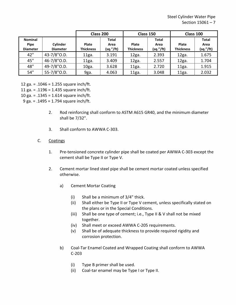
Steel Cylinder Water Pipe Section 15061 – 7
Class 200 Class 150 Class 100
Nominal Pipe
Diameter Cylinder
Diameter Plate
Thickness
Total Area
(sq.”/ft) Plate
Thickness
Total Area
(sq.”/ft) Plate
Thickness
Total Area
(sq.”/ft) 42" 43-7/8"O.D. 11ga. 3.191 12ga. 2.393 12ga. 1.675 45" 46-7/8"O.D. 11ga. 3.409 12ga. 2.557 12ga. 1.704 48" 49-7/8"O.D. 10ga. 3.628 11ga. 2.720 11ga. 1.915 54" 55-7/8"O.D. 9ga. 4.063 11ga. 3.048 11ga. 2.032
12 ga. = .1046 = 1.255 square inch/ft. 11 ga. = .1196 = 1.435 square inch/ft. 10 ga. = .1345 = 1.614 square inch/ft. 9 ga. = .1495 = 1.794 square inch/ft.
2. Rod reinforcing shall conform to ASTM A615 GR40, and the minimum diameter shall be 7/32".
3. Shall conform to AWWA C-303.
C. Coatings 1. Pre-tensioned concrete cylinder pipe shall be coated per AWWA C-303 except the
cement shall be Type II or Type V.
2. Cement mortar lined steel pipe shall be cement mortar coated unless specified otherwise. a) Cement Mortar Coating
(i) Shall be a minimum of 3/4" thick. (ii) Shall either be Type II or Type V cement, unless specifically stated on
the plans or in the Special Conditions. (iii) Shall be one type of cement; i.e., Type II & V shall not be mixed
together. (iv) Shall meet or exceed AWWA C-205 requirements. (v) Shall be of adequate thickness to provide required rigidity and
corrosion protection.
b) Coal-Tar Enamel Coated and Wrapped Coating shall conform to AWWA C-203 (i) Type B primer shall be used. (ii) Coal-tar enamel may be Type I or Type II.

Steel Cylinder Water Pipe Section 15061 – 8
(iii) Wrapping shall be a single layer of glass mat or 15-pound coal tar saturated asbestos felt.
(iv) The coating shall be whitewash.
c) Asphalt Coated and Wrap Coating shall use (i) Asphalt primer. (ii) Asphalt (hot applied). (iii) Mica surfaced 15-pound pipeline felt.
d) Field painting shall be used on above-ground installation as shown on the drawings
e) Bare metal shall be coated with a suitable primer for its intended use
D. Steel Plate Specials 1. Shall be constructed of steel plate, thickness computed from the greater of the
following criteria, unless a still greater requirement is shown on the drawings or stated in the special conditions: a) Thickness not less than 3/16"; or
b) Thickness as determined from the formula
D x P T > 2 x 12,500 Where: T = wall thickness in inches D = inside diameter of steel cylinder in inches P = design pressure (class) in pounds per square inch
2. Schedule 30 or heavier steel pipe in standard diameters may be used in lieu of
above paragraph "2.01, D1" for outlets that are 12" and smaller diameter (12.75", 10.75", 8.625", 6.625" and 4.5" outside diameters).
3. Steel welding fittings conforming to the requirements of ASTM Designation A-234 may be used when available in suitable sizes.
4. Cement mortar lining meeting AWWA C-205 except handwork reinforcement shall be 2"x 4" No. 12 welded wire fabric.
Steel Cylinder Water Pipe Section 15061 – 9
5. Coating meeting the requirements of straight pipe.
6. Stiffner plates, when required, designed per the nomograph method of AWWA
Manual M-11.
7. Reinforced steel collar pads designed for the specified pressure where needed.
8. Materials meeting or exceeding AWWA C-200 requirements.
E. Rubber Ring Gaskets 1. Shore durometer hardness range shall be in the range of 50-55 in accordance with
ASTM D-2240.
2. Compound shall conform to the requirements of Section 2.8 AWWA C-303.
2.02 MIXES All mixes shall conform to the applicable reference sections.
2.03 FABRICATION OF PIPE
A. Steel cylinder pipe shall be fabricated in accordance with: 1. AWWA C-200 for cement mortar lined steel pipe.
2. AWWA C-303 for pre-tensioned steel cylinder steel pipe.
B. Cement mortar lining process shall be followed with sealing each pipe end with a waterproof cover prior to carefully moving the pipe section. The pipe sections shall be cured under sprinklers or by other processes approved by the Engineer.
C. Coatings shall be applied after the exterior of the pipe is thoroughly cleaned and free from all loose mill scale and rust. 1. Cement mortar coating shall be applied pneumatically or by impaction resulting in
a dense uniform coating that adheres tightly to the pipe.
2. Coal-tar enamel and wrapped coating shall be applied in accordance with AWWA C-203.
3. Asphalt coating and wrapping. a) Shall be applied after pipe is fabricated and hydrostatically tested.
Steel Cylinder Water Pipe Section 15061 – 10
b) Asphalt primer.
(i) Shall be applied to clean-dry surfaces to produce a suitable bond
between the metal and subsequent coating of asphalt.
(ii) Shall be uniform and free from bare spots.
(iii) Shall be protected from rain and fog during and between applications. c) Hot asphalt shall be applied after the primer has completely hardened and
with, or immediately preceding, the wrapping material in sufficient quantity to form a bead on the exposed edge of wrap.
d) Wrapping material shall be spirally wrapped under tension to ensure complete coverage, 3/4" lap at edge, no wrinkles and buckles, and complete cementing to the pipe with hot asphalt.
e) Coating and wrapping shall be omitted at each end for a sufficient distance to permit the making of field joints. All exposed bare metal shall be coated with a suitable primer.
D. Joints 1. All pipes shall have rubber gasket joints unless otherwise shown.
a) The steel area in the bell shall not be less than the area in an equivalent
length of pipe barrel.
b) Rubber gasket ends formed integrally with the steel cylinder shall be formed either by sizing with a machined swage or die, or by rolling per AWWA C-200.
c) Separate rubber gasket joint rings shall be formed per requirements of Section 3.3 of AWWA C-303.
2. Ends that are not rubber gasket, including but not limited to weld bells, plain ends,
grooved ends, and butt straps shall conform to AWWA C-200 where applicable, and to the construction drawings.
3. Flanges shall conform to Eastern Municipal Water District standard drawing B-288.
E. Steel Plate Specials shall conform to approved shop drawings and shall be fabricated in a shop approved for that purpose by the Engineer.

Steel Cylinder Water Pipe Section 15061 – 11
1. Each special shall have a mark on the top and bottom corresponding to the true
vertical axis.
2. Outlets, including wyes, shall be built into the wall of the pipe.
3. Fabricated steel fittings of suitable design shall be welded to the cylinder before the exterior coating is placed around the fittings.
4. Cement mortar lining shall meet the requirements of straight pipe with the provisions that handwork lining reinforcement shall be positioned approximately in the center of the lining. The wires spaced 2" on center shall extend circumferentially around the pipe. The fabric shall be securely fastened to the pipe. Splices shall be lapped 4" and the free ends tied or looped to ensure continuity.
PART 3 - EXECUTION
3.01 INSPECTION
A. Notification of Manufacture. Unless specifically waived, EMWD Inspection Department shall be notified at least 48 hours prior to commencement of the manufacture of pipe.
B. Hydrostatic Testing. Steel cylinders shall be hydrostatically tested to a stress equal to 75% of the minimum yield point of the steel. Certification of all cylinders is required by the District.
C. Specials. Specials shall be bulkheaded and tested prior to lining and coating of weld seams at one-and-one-half (1½ ) times the design pressure (class). Dye penetrant process may be used on all untested welds in lieu of hydrostatic testing if the straight pipe used in fabricating the special has passed a hydrostatic test of 75% of the yield point. All defective welds including pinholes and porous welds shall be chipped out, rewelded, and retested.
D. Soap and Compressed Air Test 1. All double-welded lap joints, butt-strap joints, and other joints susceptible to this
test shall be tested by the soap and compressed air method as hereinafter described. After completion of the shop hydrostatic test of the pipe sections the soap and compressed air test also may be used instead of hydrostatic testing of welded joints in the steel manhole outlets, which are attached to steel-plate sections.

Steel Cylinder Water Pipe Section 15061 – 12
2. As soon as practicable after the welding of each joint to be tested by the soap and compressed air test has been completed, the Contractor shall subject each joint to a soap test by forcing compressed air, at approximately 40 pounds pressure per square inch, into each said joint and, while the joint is under pressure, every portion of every welded seam forming a part of the joint shall be swabbed with a heavy soap solution or an approved, commercial, bubble producing leak test fluid and shall be carefully examined for leakage. The Contractor shall repair any defects disclosed by the test by chipping out and rewelding the chipped section, after which the same test shall again be applied. The Contractor shall provide all apparatus and materials for making the tests, shall drill and tap the necessary holes and shall plug weld the holes after testing.
E. Rubber Gaskets. Rubber gaskets shall be subject to inspection and/or testing by the
Engineer. All unsatisfactory gaskets shall be immediately replaced at no expense to the District.
F. Manways. All 30" diameter and larger pipe shall have 24" diameter or larger access manways within 750 feet of any interior point of the pipeline. 1. Manways shall consist of 24" diameter outlets with 24" blind flanges.
2. Manways shall have a maximum spacing of 1500 feet on center. At valve
installations, manways shall be located on both sides of each valve a maximum of 35 feet.
3. Outlets or bumped heads that provide an equal or larger opening than a 24" manway may be used for pipe access.
4. Manway locations shall be selected to minimize impact to traffic, and shall be approved by EMWD prior to pipe fabrication.
3.02 INSTALLATION
A. Preparation. Internal bracing, in addition to the bracing used for handling and transportation of the pipe, shall be installed when required to ensure maximum permissible deflections are not exceeded during laying, backfill, and compaction.
B. Pipe Zone Density. Relative compaction in pipe zone III as shown on standard drawing B-286B shall be in accord with the manufacturer's recommendation. All pipe bid for this project shall meet EMWD's minimum standards as set forth in Section 15061 herein. The Contractor, in conjunction with the pipe manufacturer, will indicate in the space provided and attached hereto as part of the bid forms, the pipe zone compaction to be constructed, the mortar thickness - both lining and coating - and the trench slope construction.

Steel Cylinder Water Pipe Section 15061 – 13
C. Diapers shall be impervious if available. 1. Width of diapers, where used, shall be sufficient to allow cupping of the diaper for
increased thickness of the joint mortar. Recommended minimum diaper widths: a) 20" dia. pipe and larger: 12"
b) 12" - 18" dia. pipe: 10"
c) 10" dia. pipe and smaller: 9"
2. Mortar placement shall be from one side of the diaper, to allow the mortar to flow around the bottom and up the opposite side of the pipe, to preclude the possibility of any voids inside the diaper.
D. Curing operations shall begin immediately after completion of joint mortaring.
1. Immediate backfill should follow the completion of the joint mortaring operation
where possible. Care must be taken to immediately wet down and consolidate the backfill, to avoid draining the moisture from the mortar through porous diapers into dry backfill soil, or disturbing the mortar set by subsequent compaction of the backfill.
2. Completed-joint mortar to be exposed to the sunlight where backfill will not take place until after the mortar has hardened must be kept continually moist during the curing period to prevent cracking of the curing mortar.
END OF SECTION 15061

Steel Cylinder Water Pipe Section 15061 – 14
[PAGE LEFT INTENTIONALLY BLANK]

Rev: 09/06/16
SPECIFICATIONS - DETAILED PROVISIONS Section 15064 - Plastic (PVC) Pressure Water Pipe & Fittings
C O N T E N T S
PART 1 - GENERAL ............................................................................................................................. 1
1.01 REQUIREMENT .......................................................................................................................... 1 1.02 DELIVERY ................................................................................................................................... 1 1.03 QUALITY ASSURANCE ................................................................................................................ 1 1.04 MEASUREMENT AND PAYMENT ............................................................................................... 1
PART 2 - PRODUCTS AND MATERIALS ................................................................................................ 2 2.01 TYPE OF PVC PIPE ...................................................................................................................... 2 2.02 PIPE CLASS OR WORKING PRESSURE ........................................................................................ 2 2.03 TYPE OF FITTING ....................................................................................................................... 2 2.04 RESTRAINED SYSTEM ................................................................................................................ 2 2.05 SERVICE CONNECTION OUTLETS ............................................................................................... 2 2.06 POLYETHYLENE ENCASEMENT .................................................................................................. 3
PART 3 - EXECUTION ......................................................................................................................... 3 3.01 FACTORY TESTING ..................................................................................................................... 3 3.02 INSTALLATION ........................................................................................................................... 3

Plastic (PVC) Pressure Water Pipe & Fittings Section 15064 – 1
SECTION 15064 PLASTIC (PVC) PRESSURE WATER PIPE & FITTINGS
PART 1 - GENERAL
1.01 REQUIREMENT It is required that the Contractor shall furnish, deliver, unload and string along the trench site, all pipe and material as hereinafter described in the specifications. All fabrication, workmanship, material and testing of pipe shall conform to the latest revision of the specifications.
1.02 DELIVERY
A. Transport, deliver, unload, store and handle all materials in a manner to prevent damage to the materials or the work.
B. All damaged, broken or otherwise defective materials will be rejected.
C. Store all circular rubber gaskets and special lubricants in packaged materials with the manufacturer's name, brand and all other applicable data plainly marked thereon.
1.03 QUALITY ASSURANCE Unless otherwise specified, all work specified herein and as shown on the drawings shall conform to the applicable requirements of the latest revision of the following standards. Unless specifically stated otherwise, the most stringent requirement will govern when there is a conflict.
A. AWWA C-900. American Water Works Association (AWWA) C-900 standard for polyvinyl chloride (PVC) pressure pipe 4 inches through 60 inches for water.
B. Any pipe showing discoloration, chaulking, checking or other visible damage due to ultraviolet light exposure shall not be accepted by the District.
1.04 MEASUREMENT AND PAYMENT Payment for pipe shall be made on a unit price basis per lineal foot of pipe.

Plastic (PVC) Pressure Water Pipe & Fittings Section 15064 – 2
PART 2 - PRODUCTS AND MATERIALS
2.01 TYPE OF PVC PIPE PVC pipe and fabricated fittings shall be made from virgin PVC resin that has been compounded to provide physical and chemical properties that equal or exceed cell class 12454 as defined in ASTM D1784 providing a hydrostatic design basis (HDB) of 4000 p.s.i. in accordance to AWWA C-900. Pipe shall have cast iron outside diameters. All rubber rings shall be furnished by the pipe manufacturer. These rubber rings (elastomeric gaskets) shall be manufactured to conform with the requirements of ASTM F-477.
2.02 PIPE CLASS OR WORKING PRESSURE AWWA C-900 PVC pipe shall be Pressure Class 235 and shall have a Dimension Ratio of 18.0 (DR-18).
2.03 TYPE OF FITTING Fittings for PVC pipe shall be flanged or bolted mechanical joint or push-on joint ductile or gray iron fittings and shall conform to ANSI/AWWA C110/A21.10 or C153/A21.53, and ANSI/AWWA C111/A21.11. All fittings shall be cement mortar lined and tar (seal) coated in accordance with ANSI/AWWA CI04/A21.4.
2.04 RESTRAINED SYSTEM Restrained Joints shall be provided by a clamping ring and an additional ring designed to seat on the bell end of the pipe. The rings shall be connected with T-Head bolts or rods. Restraining devices shall provide full (360 degree) support around the circumference of the pipe. No point loading shall be permitted. Restraint of mechanical joint fittings shall be provided by a clamping ring installed on the PVC pipe and connected to the mechanical joint fitting with T-Head bolts or rods. Restraining devices shall meet or exceed the requirements of ASTM F-1674 or UNI-Bell B-13 "Recommended Standard Performance Specification for Joint Restrainers for Use with PVC Pipe." Restraining devices shall be UNI-Flange Series 1300 or 1350 or approved equal. All buried steel parts shall be sand blasted in accordance with the coating manufacturer's technical data sheet for "submerged" service and coated with a two coat epoxy. Epoxy shall be Tnemac Series 66 or equal. All bolts and tie rod materials shall be either high strength cast iron containing a minimum of 0.5% copper or high-strength, low alloy steel, as specified in AWWA C-111 for buried mechanical joints.
2.05 SERVICE CONNECTION OUTLETS All service connections to PVC pressure pipe water main shall be constructed with bronze service saddles with CS threads for receiving a bronze corporation stop in accordance with standard drawings. Service saddle shall be Jones, Mueller, or approved equal.
Plastic (PVC) Pressure Water Pipe & Fittings Section 15064 – 3
2.06 POLYETHYLENE ENCASEMENT All ductile or gray iron fittings shall be encased with V-Bio enhanced polyethylene at the time of installation. Polyethylene encasement and installation shall be in accordance with ANSI/AWWA C105.
PART 3 - EXECUTION
3.01 FACTORY TESTING All pipe shall be tested in the United States in accordance with AWWA C900 and certification of the testing shall be furnished to the engineer upon his request prior to delivery. The engineer may be present during physical testing of pipe.
3.02 INSTALLATION PVC pipe shall be installed in accordance with Sections 02718 and 02201 of Eastern Municipal Water District Specifications.
END OF SECTION 15064

Plastic (PVC) Pressure Water Pipe & Fittings Section 15064 – 4
[PAGE LEFT INTENTIONALLY BLANK]
Rev: 01/03/00
SPECIFICATIONS - DETAILED PROVISIONS Section 15077 - Grooved Couplings
C O N T E N T S
PART 1 - GENERAL ............................................................................................................................. 1
1.01 DESCRIPTION ............................................................................................................................. 1


Grooved Couplings Section 15077 – 1
SECTION 15077 GROOVED COUPLINGS
PART 1 - GENERAL
1.01 DESCRIPTION Where specified, mechanical grooved couplings and fittings shall be cast of malleable iron conforming to ASTM A-47 or ductile-iron ASTM A-536. The coupling shall be of the grooved, mechanical type which engages grooved pipe ends. The coupling shall be cast in two or more parts per manufacturer's standard. Coupling gasket shall be of molded synthetic rubber EPDM Grade "E" conforming to ASTM D-2000 designation 2CA615A15B44F17Z. Bolts and nuts shall be heat treated carbon steel conforming to ASTM A-183, minimum tensile 110,000 psi and oval neck track head type. Fittings shall be of grooved-end design to accept grooved mechanical couplings with or without field preparation as applicable. Couplings for grooved steel pipe shall be "Victaulic" Style 77 or approved equal. Couplings for grooved ductile iron or cast iron pipe shall be "Victaulic" Style 31 or approved equal.
END OF SECTION 15077

Grooved Couplings Section 15077 – 2
[PAGE LEFT INTENTIONALLY BLANK]

Rev: 12/17/09
SPECIFICATIONS - DETAILED PROVISIONS
Section 15081 - Gaskets
C O N T E N T S PART 1 - GENERAL ............................................................................................................................. 1
1.01 REQUIREMENT .......................................................................................................................... 1 1.02 FLANGE INSULATING GASKET KITS ........................................................................................... 1


Gaskets Section 15081 – 1
SECTION 15081 GASKETS
PART 1 - GENERAL
1.01 REQUIREMENT Gaskets for steel and cast iron flanges shall be of dimensions conforming to the requirements of Standard Drawing B-288, and shall be standard full face for pipe 27" diameter and larger. Gaskets shall be 1/16", non-asbestos model # Garlock 3000 or Tripac 5000. 1.02 FLANGE INSULATING GASKET KITS
A. Pipe flange insulating kit materials shall be of the type designated by the manufacturer as suitable for appropriate service at the operating temperatures and pressures specified on the Plans.
B. Flange insulating kits shall consist of a one piece full-face, insulating gasket, an insulating
sleeve for each bolt, two insulating washers for each bolt, and a steel washer between each insulating washer and nut.
1. Insulating gasket shall be a full faced NEMA Grade G-10 Glass Epoxy Laminated
Retainer with a precision tapered groove to accommodate the compression of a BUNA-N or VITON sealing element. Minimum total thickness shall not be less than 1/8-inch. Dielectric strength shall be not less than 550 volts per mil, and compressive strength of not less than 50,000 psi. Use PSI Linebacker or equal.
a. Optional Materials:
1. Neoprene faced phenolic gasket
2. Insulating sleeves shall be full length, one piece, insulating flange bolt sleeves for the appropriate bolt size. Insulating sleeves shall be NEMA G-10 Glass Epoxy Laminated tubing (Pyrox). Dielectric strength shall be not less than 400 volts per mil.
a. Optional Materials:
1. Phenolic tubing 2. Nomex tubing 3. Mylar tubing 4. Polyethylene tubing
3. Insulating washers shall be NEMA Grade G-10 Glass Epoxy Laminated Washers
with a minimum thickness of 1/8-inch. Dielectric strength shall not be less than 550 volts per mil, and compressive strength of not less than 50,000 psi.
Gaskets Section 15081 – 2
a. Optional Materials:
1. Phenolic Washers 2. Nomex Washers
4. Provide cadmium plated steel flange bolt washers for placement over the insulating washers with a minimum thickness of 1/8 inch.
END OF SECTION 15081
Rev: 10/19/07
SPECIFICATIONS - DETAILED PROVISIONS Section 15089 - Nuts & Bolts
C O N T E N T S
PART 1 - GENERAL ............................................................................................................................. 1
1.01 REQUIREMENT .......................................................................................................................... 1 1.02 USE OF ZINC CAPS FOR BURIED PIPE ........................................................................................ 1


Nuts & Bolts Section 15089 – 1
SECTION 15089 NUTS & BOLTS
PART 1 - GENERAL
1.01 REQUIREMENT Bolts and nuts for flanged fittings shall be bare steel conforming to SAE J429 Grade 5 or ASTM A449 medium carbon steel quenched and tempered meeting the following requirements, and shall have hex heads and lite-pattern hex nuts.
¼” Through 1" diameter
85,000 p.s.i. proof strength 92,000 p.s.i. yield strength 120,000 p.s.i. tensile strength
Over 1" to 1½” diameter
74,000 p.s.i. proof strength 81,000 p.s.i. yield strength 105,000 p.s.i. tensile strength
1.02 USE OF ZINC CAPS FOR BURIED PIPE Each bolted fitting including couplings, flange adapters, restrained joints, etc. that have manufactured bolts and nuts shall have a minimum of 2 zinc caps anodes as specified below.
Bolt sizes and number of zinc caps:
through 1" diameter - 2 zinc caps over 1" diameter - 4 zinc caps
Weight of zinc caps:
Zinc caps to be 6 oz. weight. Material reference:
Zinc caps shall be per ASTM B418-80 and Mil-A-18001J, and be manufactured by Mars, Reliance, or equal.
END OF SECTION 15089

Nuts & Bolts Section 15089 – 2
[PAGE LEFT INTENTIONALLY BLANK]

Rev: 12/03/20
SPECIFICATIONS - DETAILED PROVISIONS Section 15102 - Resilient-Seated Gate Valves
C O N T E N T S
PART 1 - GENERAL ............................................................................................................................. 1
1.01 DESCRIPTION ............................................................................................................................. 1 1.02 QUALITY ASSURANCE ................................................................................................................ 1 1.03 SUBMITTALS .............................................................................................................................. 1 1.04 PRODUCT DELIVERY .................................................................................................................. 1 1.05 JOB CONDITIONS ....................................................................................................................... 1 1.06 ALTERNATIVES........................................................................................................................... 2 1.07 GUARANTEE .............................................................................................................................. 2
PART 2 - PRODUCT ............................................................................................................................ 2 2.01 MATERIALS ................................................................................................................................ 2 2.02 COATINGS.................................................................................................................................. 2 2.03 FABRICATION AND MANUFACTURE ......................................................................................... 3
PART 3 - EXECUTION ......................................................................................................................... 3 3.01 INSPECTION ............................................................................................................................... 3 3.02 PREPARATION ........................................................................................................................... 4

Resilient-Seated Gate Valves Section 15102 – 1
SECTION 15102 RESILIENT-SEATED GATE VALVES
PART 1 - GENERAL
1.01 DESCRIPTION The Contractor shall furnish, deliver, and unload within the time specified in the Special Conditions, the resilient-seated gate valves as hereinafter described.
1.02 QUALITY ASSURANCE Quality Assurance includes the requirements of this specification and the requirements of the latest revision of the following standards, as applicable. Unless specifically stated otherwise, the most stringent requirement will govern when there is a conflict.
A. AWWA C-509. American Water Works Association Standard for Resilient Seated Gate Valves, 3" through 30" NPS, for Water and Sewage Systems
B. AWWA C-515. American Water Works Association Standard for Reduced–Wall, Resilient Seated Gate Valves, 3”-16” & 3”-36” NRS.
C. AWWA C-550. American Water Works Association Standard for Protective Interior Coatings for Valves and Hydrants.
1.03 SUBMITTALS The name of the manufacturer of the valves to be furnished by the bidder shall be stated on the bidding sheets. Proposed valves other than those listed on the EMWD approved Material List must be submitted for evaluation well in advance of the bid opening, for acceptance prior to the award of the contract. Generally, the specified 35-day period following issuance of the Notice-of-Acceptance-of-Proposal is not sufficient for approval of alternate valves.
1.04 PRODUCT DELIVERY
A. Storage. Valves shall be stored in the closed position to protect seating surfaces.
B. Handling. Valves shall be carefully lowered from the truck to the ground. Do not hook hoists or fasten chains around stem, gearing, motors, cylinders, or handwheels.
1.05 JOB CONDITIONS Valves shall not be fabricated, stored, coated, or installed in climatic conditions that will adversely affect the quality of the finished project.

Resilient-Seated Gate Valves Section 15102 – 2
1.06 ALTERNATIVES Valve ends shall be as specified on the bidding sheet, plans or specifications as applicable; these may be flanged both ends, hub-end both ends, or one flanged end and one hub-end, conforming to the following specifications:
A. Flanged End. Flanged ends shall be designed for the water pressure as specified in AWWA C-509 and drilled to the American Standard for 125# Cast Iron Flanges, and flange face shall not be raised. Flange face shall have standard machine finish.
B. Hub-End. Hub-ends shall be designed for the water pressure as specified in AWWA C-509 and shall be "Ring-tite", "Fluid-tite" or approved equal.
1.07 GUARANTEE Contractor shall guarantee all materials and workmanship of items furnished under these specifications shall be free from defects for a period of one (1) year after final completion and acceptance of the entire contract work. The Contractor shall, at his own expense, repair or replace all defective materials or workmanship supplied by him that are found to be deficient with respect to any provisions of this specification.
PART 2 - PRODUCT
2.01 MATERIALS Resilient Seated Gate Valves shall include the following materials:
A. Non-Rising Stems. Clockwise to close, counterclockwise to open. Valve stems shall be of bronze, having a minimum tensile strength of 55,000 psi and a yield point of not less than 40,000 psi, with an elongation of not less than 10% in 2". Heat treatment will be permitted to develop these requirements. All bronze shall contain not more than 7% zinc nor more than 2% aluminum.
B. 2" Square Nut with arrow cast in metal to indicate opening direction, except where specified otherwise.
C. Resilient Seats may be bonded or mechanically attached to either the gate or valve body.
2.02 COATINGS A. All valves shall have internal and external ferrous parts epoxy coated. Wetted surfaces
shall have an 8 mil minimum (dry film) thickness, unless otherwise specified. The epoxy shall be approved for potable water, and shall conform to AWWA C-550.
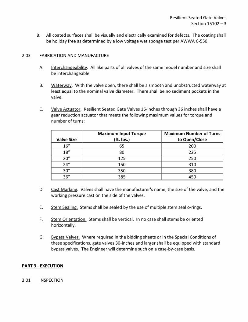
Resilient-Seated Gate Valves Section 15102 – 3
B. All coated surfaces shall be visually and electrically examined for defects. The coating shall
be holiday free as determined by a low voltage wet sponge test per AWWA C-550.
2.03 FABRICATION AND MANUFACTURE
A. Interchangeability. All like parts of all valves of the same model number and size shall be interchangeable.
B. Waterway. With the valve open, there shall be a smooth and unobstructed waterway at least equal to the nominal valve diameter. There shall be no sediment pockets in the valve.
C. Valve Actuator. Resilient Seated Gate Valves 16-inches through 36 inches shall have a gear reduction actuator that meets the following maximum values for torque and number of turns:
Valve Size Maximum Input Torque
(ft. lbs.) Maximum Number of Turns
to Open/Close 16” 65 200 18” 80 225 20” 125 250 24” 150 310 30” 350 380 36” 385 450
D. Cast Marking. Valves shall have the manufacturer's name, the size of the valve, and the
working pressure cast on the side of the valves.
E. Stem Sealing. Stems shall be sealed by the use of multiple stem seal o-rings.
F. Stem Orientation. Stems shall be vertical. In no case shall stems be oriented horizontally.
G. Bypass Valves. Where required in the bidding sheets or in the Special Conditions of these specifications, gate valves 30-inches and larger shall be equipped with standard bypass valves. The Engineer will determine such on a case-by-case basis.
PART 3 - EXECUTION
3.01 INSPECTION
Resilient-Seated Gate Valves Section 15102 – 4
A. Hydrostatic Tests. All valves shall have hydrostatic shell test of 400 psi and a bubble tight shut-off test of 200 psi.
B. Coating Tests. All coated surfaces shall be visually and electrically examined for defects. The coatings shall be holiday free with a low voltage wet sponge test per AWWA C-550.
C. Operation Test. Each valve shall be operated through one complete cycle in the position for which it is designed, to ensure proper functioning of all parts.
D. Additional Testing (RSGVs 16-inch and Larger). Resilient Seated Gate Valves 16-inch and larger shall be hydrostatically tested and performance tested per AWWA C509 and C515. This test shall be conducted within 100 miles of the District office and shall be performed in the presence of a District Inspector. No valve shall be installed until this testing has been completed and approved by the District. Each valve shall be tested as detailed in AWWA and District Standard Specifications and as specified below: 1. Visually inspect each valve for obvious damage, substandard construction and
compliance with specifications. 2. Each valve shall be operated through one complete cycle in the position for which
it is designed, to ensure proper functioning of all parts. 3. Each valve shall be hydrostatically tested at its rated pressure. The testing
medium shall be water (no air shall be used as the test medium under any circumstance). Both sides of the valve are to be tested.
4. The test duration on each side of the valve shall be 5 minutes. A passing test is one where there is no visible leakage and no decrease in the initial test pressure.
5. A valve that fails the hydrostatic test shall be either repaired or replaced. Repaired/replaced valves shall be retested using the same procedure.
6. Valves shall only be repaired by personnel authorized by the valve manufacturer. Unless specifically authorized by the valve manufacturer, supplier or contractor shall not be permitted to perform repairs.
E. Records. After installation, each valve location, size, make, type, date of installation,
and number of turns to open shall be documented by the Contractor and furnished to District Operations through the District Inspector.
3.02 PREPARATION Valves shall be complete when shipped. They shall be drained and closed before shipment.
END OF SECTION 15102

Rev: 01/20/06
SPECIFICATIONS - DETAILED PROVISIONS Section 15103 - Butterfly Valves
C O N T E N T S
PART 1 - GENERAL ............................................................................................................................. 1
1.01 REQUIREMENT .......................................................................................................................... 1 1.02 VALVE MANUFACTURER ........................................................................................................... 1 1.03 GUARANTEE .............................................................................................................................. 1
PART 2 - PRODUCT ............................................................................................................................ 1 2.01 VALVES ...................................................................................................................................... 1 2.02 VALVE ENDS .............................................................................................................................. 1 2.03 OPERATORS ............................................................................................................................... 2 2.04 TESTS ......................................................................................................................................... 2 2.05 COATINGS.................................................................................................................................. 3


Butterfly Valves Section 15103 – 1
SECTION 15103 BUTTERFLY VALVES
PART 1 - GENERAL
1.01 REQUIREMENT Butterfly valves for buried water system service. Under this specification the Contractor shall be required to furnish, deliver, and unload within the time specified in the Special Conditions, the butterfly valves as specified on the bidding sheets and hereinafter described in these specifications.
1.02 VALVE MANUFACTURER The name of the manufacturer of the valves to be furnished by the bidder shall be stated on the bidding sheets. Inasmuch as valves require an in-service review over an extended period of time for evaluation by the District for acceptance, it is necessary that proposed valves other than those specified must be submitted for evaluation well in advance of the bid opening, for acceptance prior to the award of the contract. Generally, the specified 35-day period following issuance of the Acceptance-of-Proposal will not result in approval of alternate valves.
1.03 GUARANTEE The Contractor shall guarantee all materials and workmanship of items furnished under these specifications to be free from defects for a period of one (1) year after final completion and acceptance of the entire contract work. The Contractor shall, at his own expense, repair or replace all defective materials or workmanship supplied by him found to be deficient with respect to any provisions of this specification.
PART 2 - PRODUCT
2.01 VALVES Butterfly valves shall conform to the latest revision of AWWA Standard C-504 for rubber-seated butterfly valves, subject to the following requirements: Valves shall be of Class 150B, shall have 125-lb. American Standard flanges and, unless otherwise shown, shall be short-bodied. Shaft seals shall be rubber "O"-ring, and journal packing shall be rubber or split-V type packing. All valves shall be new and of current manufacture and shall be per EMWD Acceptance list.
2.02 VALVE ENDS Shall be as specified on the bidding sheet; either flanged both ends, hub-end both ends, or one flanged end and one hub-end, as required, conforming to the following specifications:

Butterfly Valves Section 15103 – 2
A. Flanged End. Flanged ends shall be designed for the water pressure as specified in AWWA C-504 and drilled to the American Standard for 125# Cast Iron Flanges, and flange face shall not be raised. Flange face shall have standard machine finish.
B. Hub-End. Hub-ends shall be designed for the water pressure as specified in AWWA C-504 and shall be "Ring-tite" or approved equal.
2.03 OPERATORS The valve shall be provided with a totally enclosed buried service operator designed for the full working pressure across the disc and conforming to the requirements of the above-referenced AWWA Standard. Valves shall be installed with the shaft in a horizontal position. The operators shall be side-mounted, equipped with a 2" operating nut and have a raised boss at the input shaft to accommodate a 5" pipe. The operating torque rating shall conform to Table I of the above referenced AWWA Standard for the pressure classification specified, and shall be designed in accordance with the requirements of AWWA C-504-80 Appendix. Operator input torque ratings shall fully comply with the above referenced AWWA Standard. Operation shall be clockwise to close, counterclockwise to open. The minimum number of turns to close valve shall have a minimum of two (2) turns per diameter inch and a maximum of five (5) turns per diameter inch of valve size. Valve operator shall be oriented with respect to pipeline intersection in accordance with standard drawing No. B-577.
2.04 TESTS Each valve body shall be tested by the manufacturer under a test pressure equal to twice its design water working pressure, and shall be shop-operated three (3) times in accordance with the requirements of AWWA Standard C-504.
C. BUTTERFLY VALVES LARGER THAN 12-INCHES Butterfly Valve Testing. Butterfly valves with size greater than 12 inches shall be hydrostatically tested per AWWA C504 in both directions. This test shall be conducted within 50 miles of the District office and shall be performed in the presence of the District. No valve shall be installed until this testing has been completed and approved by the District. Each valve shall be tested as detailed in the District Standard Specifications and as specified below: 1. Visually inspect each valve and its actuator for compliance with the submittal.
2. Visually inspect each valve for obvious damage or substandard construction.
3. The testing medium shall be water. Under no circumstances is air to be used as
the test medium.
Butterfly Valves Section 15103 – 3
4. Each valve is to be tested at its rated pressure.
5. Both sides of each valve are to be tested.
6. The test duration on each side of the valve is 5 minutes. A passing test is one
where there is no visible leakage and no decrease on the initial test pressure.
7. A valve which fails the pressure test shall be either repaired or replaced. Repaired valves shall be retested. Replacement valves shall be tested using this procedure.
8. Valves shall only be repaired by personnel authorized by the valve manufacturer to do the necessary repairs. Unless they have been authorized by the valve manufacturer, supplier or contractor shall not be permitted to perform repairs.
2.05 COATINGS
A. All valves shall have internal and external ferrous parts epoxy coated. Wetted surfaces shall have an 8 mil minimum (dry film) thickness, unless otherwise specified. The epoxy shall be approved for potable water, and shall conform to AWWA C-550.
B. All coated surfaces shall be visually and electrically examined for defects. The coating shall be
holiday free as determined by a low voltage wet sponge test per AWWA C-550.
END OF SECTION 15103

Butterfly Valves Section 15103 – 4
[PAGE LEFT INTENTIONALLY BLANK]
Rev: 08/94
SPECIFICATIONS - DETAILED PROVISIONS Section 15104 - Ball Valves
C O N T E N T S
PART 1 - GENERAL ............................................................................................................................. 1
1.01 SUMMARY ................................................................................................................................. 1 1.02 REFERENCES .............................................................................................................................. 1 1.03 SUBMITTALS .............................................................................................................................. 1
PART 2 - PRODUCTS .......................................................................................................................... 1 2.01 METAL BODY BALL VALVES ....................................................................................................... 1 2.02 PLASTIC BODY BALL VALVES ..................................................................................................... 2
PART 3 - EXECUTION ......................................................................................................................... 3 3.01 INSTALLATION ........................................................................................................................... 3

Ball Valves Section 15104 – 1
SECTION 15104 BALL VALVES
PART 1 - GENERAL
1.01 SUMMARY
A. Section Includes. (Metal body ball valves) (and) (plastic body ball valves)
1.02 REFERENCES
A. American Water Works Association (AWWA):
1. C 507 Ball Valves, Shaft or Trunnion Mounted, 6 Inch Through 48 Inch.
1.03 SUBMITTALS
A. Product Data
B. Metal Body Ball Valves: Affidavit of compliance with AWWA C 507.
PART 2 - PRODUCTS
2.01 METAL BODY BALL VALVES
A. Manufacturers: One of the following or equal.
1. Lunkenheimer Company.
2. MARPAC, Inc.
B. General
1. Type: Non-lubricated, and capable of sealing in either flow direction.
2. Conform to AWWA C 507.
3. Stem Packing: Manually adjustable while valve is under pressure.

Ball Valves Section 15104 – 2
4. Temperature Limits: Suitable for operation between minus 20 and 350 degrees Fahrenheit.
C. Materials
1. Valves in copper lines: Bronze body with solder ends.
2. Valves in steel and ductile iron piping: Ductile iron or cast steel bodies, and ends
as follows:
a) Threaded for sizes 3 inch and smaller.
b) Flanged for sizes larger than 3 inch. 3. Ball: Type 304 or Type 316 stainless steel.
4. Seats: TFE.
5. Stem seals: TFE or Viton.
2.02 PLASTIC BODY BALL VALVES
A. Manufacturers: One of the following or equal:
1. Asahi America
2. Chemtrol Division, NIBCO Inc.
B. General:
1. Type: Non-lubricated and capable of sealing in either flow direction.
2. End connections: True union.
3. Operator handle: Lever
C. Materials:
1. Body: Polyvinyl chloride (PVC).
2. Ball: Polyvinyl chloride (PVC).
3. Seats: TFE (Teflon).

Ball Valves Section 15104 – 3
4. O-rings: [FPM (Viton)] (EPDM).
PART 3 - EXECUTION
3.01 INSTALLATION
A. Follow manufacturer's published instructions.
END OF SECTION 15104

Ball Valves Section 15104 – 4
[PAGE LEFT INTENTIONALLY BLANK]

Rev: 03/87
SPECIFICATIONS - DETAILED PROVISIONS Section 15120 - Control Valves
C O N T E N T S
PART 1 - GENERAL ............................................................................................................................. 1
1.01 REQUIREMENT .......................................................................................................................... 1 PART 2 - PRODUCT ............................................................................................................................ 1
2.01 CONTROL VALVES ..................................................................................................................... 1


Control Valves Section 15120 – 1
SECTION 15120 CONTROL VALVES
PART 1 - GENERAL
1.01 REQUIREMENT Under these specifications the Contractor shall be required to furnish, deliver and unload at the place stated, and within the time specified in the Special Requirements of these specifications, the valves as hereinafter described in these specifications.
PART 2 - PRODUCT
2.01 CONTROL VALVES All control valves shall be flanged diaphragm type globe valves, with cast iron body, as manufactured by Cla-Val Company, or shall be of other makes approved by Eastern Municipal Water District. Type and size shall be as shown on the Bidding Sheets.
A. Coatings. All wetted ferrous parts, except stainless steel, shall be epoxy coated. The epoxy shall be thermosetting, approved for potable water, and conform to AWWA C-550.
B. Stems. Plastic sleeved stems (Delrin) shall be supplied except when specifically deleted.
C. Trim 1. Pressure Reducing Valves: Unless specifically stated otherwise, pressure reducing
control valves shall have stainless steel trim.
2. Other Control Valves: All control valves other than pressure reducing valves shall have bronze trim.
END OF SECTION 15120

Control Valves Section 15120 – 2
[PAGE LEFT INTENTIONALLY BLANK]
Electric Valve Actuators (Custom) Section 15135-1
SECTION 15135
ELECTRIC VALVE ACTUATORS
PART 1 - GENERAL
1-1. SUMMARY
Section Includes: Electric motor-operated valve and gate actuators and accessories.
1-2. REFERENCES
AWWA C540-87, Standard for Power Actuating Devices for Valves and Sluice Gates.
U.L. 429, Electrically Operated Valves.
1-3. SUBMITTALS
1-3.01. Coordination with Valve and Gate Submittals. Electric actuator and valve/gate information shall be submitted together in a complete package that fully describes both the actuator and the equipment that it is serving. Valves that do not require electric actuators shall be submitted separately.
1-3.02. Shop Drawings and Product Data. Submit the following as a single complete initial submittal in accordance with General Conditions and requirements specified herein.
Product data fully describing all items proposed for use to demonstrate that the equipment conforms to the Specifications.
Motor data, including requirements for circuitry. Verify the circuits shown in the electrical drawings will accommodate the submitted actuator. Elementary and connection wiring diagrams clearly showing external connections to other equipment. Drawings showing the actuator and valve or gate in its installed configuration. Layout drawing for all control panels, user interfaces, etc.
Calculations supporting torque/motor horsepower calculations, including opening, closing, seating and unseating torque requirements for actuated valves and gates. Torque calculations shall include torque required to open the seated valve or gate against its design pressure/seating head on one side and atmospheric pressure on the other. All actuators supplied for the project, regardless of valve or gate manufacturer, shall be provided in a single submittal.
1-3.03. Factory Testing. Submit certified non-witnessed factory performance test results. Receive favorable review of test results prior to shipping the equipment.

Electric Valve Actuators (Custom) Section 15135-2
1-3.04. Manuals. Furnish manufacturer's installation, lubrication, operation and maintenance manuals, bulletins, and spare parts lists.
1-3.05. Affidavits. Submit affidavits from the manufacturer stating that the equipment has been properly installed, adjusted, and tested, and is ready for full-time operation.
1-4. QUALITY ASSURANCE
1-4.01. Qualifications. Equipment furnished under this Section shall be supplied by a single manufacturer who has been regularly engaged in the design and manufacture of the equipment for at least 5 years. The supplier of the equipment shall have local, factory-trained personnel capable of servicing both the actuator and connected equipment.
1-4.02. Regulatory Requirements. All units shall be either CSA or FM listed, and have the listing identified on the equipment nameplate.
1-4.03. Electric actuators shall be provided from the valve manufacturer as an assembled unit, with the actuator attached. Delivery of a bare-stem with field installation of the actuator is not allowed unless approved in writing by the Engineer.
1-4.04. System Responsibility. It shall be the responsibility of the motorized valve actuator manufacturer to furnish the valve, actuator, and required software, field startup, and coordination with I&C subcontractor specified in Section 17010.
1-5. DELIVERY, STORAGE, AND HANDLING
Immediately upon delivery to job site, place materials in area protected from weather. Use non-marring slings for loading, unloading, and handling units to prevent rope or cable damage to surfaces and protective wrappings.
1-6. WARRANTY
The warranty for all products and work shall comply with the requirements of the Contractor's General Warranty and Guarantee described in the General Conditions and the Supplementary Conditions.
PART 2 - PRODUCTS
2-1. MOTORIZED ACTUATORS
2-1.01. General: Motorized actuator for valves shall consist of a motor actuator, motor starter, limit switches, and electronic controls for modulation where applicable.
2-1.02. Actuators shall be capable of either modulating or open/close service, as indicated on the Valve and Gate Actuator Schedules. Actuators shall include all accessories for accommodating multi-turn, quarter-turn, rising stem, or other actuation methods as required for the particular valve or gate. All actuators shall be equipped with a Modbus communication card designed for a communication network to a programmable logic controller (PLC) as specified in Section 17010.

Electric Valve Actuators (Custom) Section 15135-3
2-1.03. Housing: The actuator housing shall be cast aluminum with a ductile iron thrust base. The housing shall be rated for water-tight service in up to 6 feet of submersion for 30 minutes.
2-1.04. Motor: Motors shall operate on 240 VAC, 3-phase, 60 Hz power, and be rated for 60 starts per hour unless noted otherwise. Motors shall be of the high torque type, designed for continuous duty rating at a minimum of 140°F, and include Class F insulation. The motor shall be totally enclosed and non-ventilated with all leads terminating within the limit switch compartment. The gear attachment and electrical connections shall include plug-in type connectors to allow removal of the motor without disassembly of the actuator.
2-1.05. Gear Set: Gearing shall include an alloy steel worm and bronze worm gear immersed in oil lubrication. All gearing shall be bearing supported.
2-1.06. Gear Reduction Assembly: The gear reduction unit shall be selected by the valve manufacturer for reducing the rotational speed from actuator. For quarter-turn valves, operating time from fully open to fully closed shall be less than 60 seconds.
2-1.07. Controls Provide integral electrical controls with indicating lights, local-remote selector, and open-stop-close selector.
Provide Modbus communication for all signals as shown on the Drawings.
2-1.08. Manual Controls: Each actuator shall include a declutch lever and handwheel for manual operation. Handwheel shall provide for operation independent of motor gears.
2-1.09. Protective and Monitoring Devices:
Each motor shall include thermal motor overload protection. Overload protection shall be provided by thermal trip circuit breakers embedded in the motor windings.
A monitor relay shall de-energize the motor in the event of loss of power supply phase, control circuit supply, thermostat trip, local control selection, or local stop selection.
The actuator shall include a torque sensor and circuitry to de-energize the motor if no movement occurs after an open or close signal.
Valve or gate position shall be monitored by an optical encoding device. The encoder shall track and display valve position in either motor or handwheel operation, and in the event of power loss.
2-1.10. Termination Chamber: All electrical connections shall be made in a termination chamber that is separated from the control chamber by a double seal. The control chamber shall be completely enclosed when making electrical connections.
Electric Valve Actuators (Custom) Section 15135-4
2-1.11. Indicators: The actuator shall include a local backlight LCD display for position, torque, setup, and diagnostic information. Lights shall also be provided for visual indication of status, including "open" and "closed" positions.
2-1.12. Actuator Sizing: The actuator size shall be determined by the actuator supplier, based on requirements supplied by the valve or gate supplier for this project. At a minimum, the actuator shall be of sufficient size to open or close the valve or gate at 200% of the maximum required opening, closing, and operating torque at the valve's or gate's design pressure or seating head.
2-1.13. Finish: All actuators shall be primed with an epoxy coating and electrostatically powder-coated at the factory.
2-1.14. Non-intrusive Settings: The actuator covers shall not be required to be removed for site commissioning. All settings and adjustments shall be made from the exterior of the control enclosure, without exposing internal components. Control selectors shall be non-intrusive, with no moving shafts penetrating the control enclosure.
2-1.15. Additional Requirements for Open-Close Actuators: Provide integral electric controls for open-close service including reversing starter, limit switches, torque switch, indicating lights and local-off-remote switch. Comply with AWWA C540. Controls shall include accept dray contacts for remote open/close operation and shall provide a "in Auto" dry contact for connection to PLC control system.
2-1.16. Additional Requirements for Modulating Actuators:
Valves and Gates indicated for modulating service in the Valve and Gate Actuator Schedules shall include solid-state starters rated for 1,200 starts per hour.
Deadband response shall be less than 0.1% of range. Zero and span adjustments shall be provided.
Modulating actuator shall accept a 4-20 mA external signal in remote mode and shall provide a two-wire 4-20mA position feedback signal.
Communication to the control system shall be via DeviceNet. Position control and feedback shall be via the DeviceNet network.
2-1.17. Manufacturer: Auma, Bettis/EIM, or Rexa, no equals.
2-2. DEVICENET COMMUNICATION SYSTEM
2-2.01. Communication card in each motorized valve and gate actuator.
Provide a microprocessor-based card within actuator to communicate over a DeviceNet communication system. The communication card shall monitor and control valve functions of at least the following:
Commands Signals: Open, close, modulate.

Electric Valve Actuators (Custom) Section 15135-5
Status Signals: Opened, closed, valve position.
Local switch status: "Local" or "Auto."
Valve data such as valve jammed, torque trip, valve position.
Other adjustments for modulating services.
2-2.02. The card shall be equipped with power derived from actuator and shall communicate over thick 600V round cable trunk line and drop wiring to Allen Bradley ControlLogix or CompactLogix PLCs with DeviceNet Scanner modules in the PLCs as shown on the Drawings.
2-2.03. The actuators shall be controlled over a DeviceNet digital communication control system. Network communication speed shall be configurable up to 500 K baud using DeviceNet Protocol. Valves shall serve as "slaves" to the PLC card, which will be the "Master."
2-2.04. Card shall include surge suppression modules.
2-2.05. PLC Communication Card(s) in Programmable Logic Controller: Provide Allen Bradley DeviceNet Scanner modules as indicated on the Drawings. Coordinate with the PLC supplier and the I&C subcontractor as specified in Section 17010.
2-2.06. Wiring Requirements: Submit on a cabling diagram for all valves indicated on the Drawings. Indicate required junction or terminal boxes, wire type and other features. Communicate those requirements to the electrical subcontractor. Diagram shall include area by area connections. Electrical diagrams shall indicate the conduit runs. It is the responsibility of the motorized valve supplier to coordinate wiring and conduit layout with the electrical subcontractor.
2-2.07. Device Drivers: Provide the services of the actuator manufacturer engineers to furnish any required drivers, software for a complete operating system.
2-2.08. Configuration Software: Provide one copy of configuration software for valve network complete with manuals.
PART 3 - EXECUTION
3-1. INSTALLATION
Install in strict conformance with the manufacturer's installation instructions.
3-2. FIELD SERVICE
3-2.01. Durations specified in Field Services do not include travel time to or from the project site or additional time required for retesting.
Electric Valve Actuators (Custom) Section 15135-6
If there are difficulties in operation of the equipment due to the design, fabrication, or installation, additional service shall be provided at no cost to the Owner.
3-2.02. Performance Testing: Performance test all valves, gates, and actuators. Provide the services of factory trained engineer for at least 3 days to provide valve network configuration and testing after the submittal of shop drawings and 2 days during the factory test of the PLC system specified in Section 17010. Factory-trained engineer shall provide hardware and software support for configuring the valves and network. Factory-trained engineer shall be present at the PLC Factory Test specified in Section 17010.
3-2.03. Training: Provide 10 hours of additional service by an engineer or technician from the equipment supplier to train plant personnel in actuator operation, maintenance, and safety procedures.
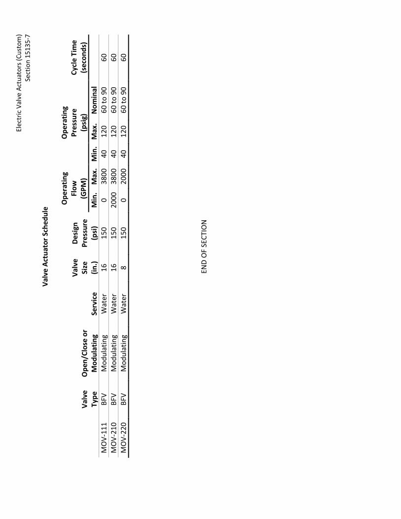
El
ectr
ic V
alve
Act
uato
rs (C
usto
m)
Sect
ion
1513
5-7
Va
lve
Actu
ator
Sch
edul
e
Va
lve
Type
O
pen/
Clos
e or
M
odul
atin
g Se
rvic
e
Valv
e Si
ze
(in.)
Desi
gn
Pres
sure
(p
si)
Ope
ratin
g Fl
ow
(GPM
)
Ope
ratin
g Pr
essu
re
(psi
g)
Cycl
e Ti
me
(s
econ
ds)
Min
. M
ax.
Min
. M
ax.
Nom
inal
MO
V-11
1 BF
V M
odul
atin
g W
ater
16
15
0 0
3800
40
12
0 60
to 9
0 60
M
OV-
210
BFV
Mod
ulat
ing
Wat
er
16
150
2000
38
00
40
120
60 to
90
60
MO
V-22
0 BF
V M
odul
atin
g W
ater
8
150
0 20
00
40
120
60 to
90
60
END
OF
SECT
ION

Electric Valve Actuators (Custom) Section 15135-8
THIS PAGE INTENTIONALLY BLANK

Rev: 03/95
SPECIFICATIONS - DETAILED PROVISIONS Section 15136 - Air Valves
C O N T E N T S
PART 1 - GENERAL ............................................................................................................................. 1
1.01 Requirement ............................................................................................................................. 1 1.02 Valve Manufacturer .................................................................................................................. 1 1.03 Guarantee ................................................................................................................................. 1
PART 2 - PRODUCT ............................................................................................................................ 1 2.01 Materials ................................................................................................................................... 1 2.02 Operational Features ................................................................................................................ 1 2.03 System Air Valves ...................................................................................................................... 2 2.04 Pump Air Valves ........................................................................................................................ 2


Air Valves Section 15136 – 1
SECTION 15136 AIR VALVES
PART 1 - GENERAL
1.01 REQUIREMENT Under these specifications the Contractor shall be required to furnish, deliver and unload at the place stated, and within the time specified in the Special Provisions, the air valves for water systems as specified on the Bidding Sheet and hereinafter described in these specifications. Air valves for sewerage systems are not included in this specification, but will be specifically called out on the construction drawings.
1.02 VALVE MANUFACTURER The name of the manufacturer of the valves to be furnished by the bidder shall be stated on the Bidding Sheet. If valves different than listed herein are proposed, the bidder shall submit drawings of the proposed valves to the District prior to the time of opening bids. Bidder's drawings need not be submitted if such drawings have previously been approved by the Engineer as to compliance with the specifications.
1.03 GUARANTEE The Contractor shall guarantee all materials and workmanship of items furnished under these specifications shall be free from defects for a period of one (1) year after final completion and acceptance of the entire contract work. The Contractor shall, at his own expense, repair or replace all defective materials or workmanship supplied by him found to be deficient with respect to any provisions of this specification.
PART 2 - PRODUCT
2.01 MATERIALS All valves shall have a body of high grade cast iron and have all internal parts of solid bronze or stainless steel. All valves shall be designed for a working pressure of not less than 150 p.s.i..
2.02 OPERATIONAL FEATURES
A. Air Valves. All valves shall be designed to automatically operate as specified herein: 1. Will positively open under atmospheric pressure to allow air to escape from the
pipe through the valve.

Air Valves Section 15136 – 2
2. Will positively close as water under low head fills body of the valve.
3. Will not blow shut under high velocity air discharge, to allow air to escape from pipe while pipe is being filled.
4. Will permit the escape of accumulated air under pressure, while pipeline is in operation.
B. Air-Vacuum Valves. Shall be designed to automatically permit the rapid egress of large
amounts of air from the pipeline while the pipeline is being filled with water, and to permit the rapid ingress of large amounts of air into the pipeline while the pipeline is being emptied.
C. Air Release Valves. Shall be designed to automatically permit the escape of small amounts of accumulated air from pipelines operating under pressure.
D. Combination Air-Vacuum and Air Release Valves. Shall be designed to automatically operate as described above for air-vacuum valves and air release valves.
2.03 SYSTEM AIR VALVES Air valves for use in distribution systems shall be the float and lever type of the makes listed herein, or equal as approved by the Engineer:
Manufacturer Sizes
Air Release Valves Apco #65 3/4"
Air Release & Vacuum Valves Apco 143-C 1" Apco 145-C 2" Valmatic 201-C 1" Valmatic 202-C 2" Crispen U-10 1" Crispen U-20 2" Apco 149-C 4" Apco 150-C 6"
2.04 PUMP AIR VALVES All air release valves for use on pumps shall have 3/4" pipe connection and shall be Armstrong Machine Works No. 21 AR Air Relief Trap, or equal as approved by the Engineer.
END OF SECTION 15136

Rev: 09/16/99
SPECIFICATIONS - DETAILED PROVISIONS Section 15340 - Manholes and Fittings
C O N T E N T S
PART 1 - GENERAL ............................................................................................................................. 1
1.01 REQUIREMENT .......................................................................................................................... 1 1.02 MEASUREMENT AND PAYMENT ............................................................................................... 1 1.03 GUARANTEE .............................................................................................................................. 1
PART 2 - PRODUCTS .......................................................................................................................... 1 2.01 MANHOLES ................................................................................................................................ 1 2.02 RINGS ........................................................................................................................................ 1 2.03 TOPS .......................................................................................................................................... 1 2.04 MANHOLE COVERS.................................................................................................................... 2 2.05 MANHOLE STEPS ....................................................................................................................... 2


Manholes and Fittings Section 15340 – 1
SECTION 15340 MANHOLES AND FITTINGS
PART 1 - GENERAL
1.01 REQUIREMENT Under this specification, the Contractor shall be required to furnish, deliver and unload within the time specified in the Contract Documents, the manholes and fittings as specified on the Bidding Sheets, shown on the Contract Drawings, and described in these specifications, except as otherwise approved in writing by the Engineer.
1.02 MEASUREMENT AND PAYMENT Payment for quantities of manholes will be made at the unit prices as stated on the Bidding Sheets.
1.03 GUARANTEE The Contractor shall guarantee all materials and workmanship of items furnished under these specifications to be free from defects for a period of one (1) year after final completion and acceptance of the entire contract work. The Contractor shall, at his own expense, repair or replace all defective materials or workmanship supplied by him found to be deficient with respect to any provisions of this specification.
PART 2 - PRODUCTS
2.01 MANHOLES All manhole rings, tops, and cones, as constructed in place, shall be designed for A.A.S.H.O. H-20 highway loading, and shall conform to District standard drawings and the requirements of ASTM C-478 and the following requirements.
2.02 RINGS All manhole rings shall be centrifugally spun or compactly vibrated in forms.
2.03 TOPS All manhole tops and cones shall be compactly vibrated in forms.

Manholes and Fittings Section 15340 – 2
2.04 MANHOLE COVERS All manhole covers and frames shall conform to District standard drawings and the requirements for Class 30 gray iron castings in ASTM Designation A-48, or Class 60 Ductile Iron castings in ASTM A-536. The castings shall be thoroughly cleaned and coated with commercial quality asphaltum paint. Frames and covers shall be matchmarked in pairs before delivery to the work site and must be machined matched between cover and frame to avoid rocking.
2.05 MANHOLE STEPS Manhole steps shall conform to District Standard Drawings and shall be constructed of 1/2" plain steel bar incapsulated with copolymer polypropylene plastic as approved by EMWD. Alternate to be approved by EMWD for casting-in-place.
END OF SECTION 15340

Revised 04/14/16
SPECIFICATIONS - DETAILED PROVISIONS Section 16010 - General Electrical Requirements
C O N T E N T S
PART 1 - GENERAL ....................................................................................................................... 1
1.01 DESCRIPTION .............................................................................................................. 1 1.02 QUALITY ASSURANCE................................................................................................... 1 1.03 UTILITY COMPANY REQUIREMENTS .............................................................................. 5 1.04 SUBMITTALS ............................................................................................................... 6 1.05 PRODUCT DELIVERY, STORAGE, AND HANDLING .......................................................... 10 1.06 COORDINATION OF WORK AND TRADES ..................................................................... 11 1.07 COORDINATION OF THE ELECTRICAL SYSTEM .............................................................. 12 1.08 RELATED WORK SPECIFIED ELSEWHERE ....................................................................... 12 1.09 PERMITS ................................................................................................................... 13 1.10 OUTAGES .................................................................................................................. 13 1.11 AREA CLASSIFICATION DESIGNATIONS ........................................................................ 13 1.12 WARNING SIGNS ....................................................................................................... 14 1.13 GUARANTEE AND WARRANTY .................................................................................... 15
PART 2 - PRODUCTS ................................................................................................................... 15 2.01 MATERIALS AND EQUIPMENT .................................................................................... 15
PART 3 - EXECUTION .................................................................................................................. 16 3.01 GENERAL ................................................................................................................... 16 3.02 ELECTRICAL SUPERVISION .......................................................................................... 16 3.03 INSPECTION .............................................................................................................. 16 3.04 PREPARATION ........................................................................................................... 17 3.05 WORKMANSHIP ........................................................................................................ 17 3.06 PROTECTIVE DEVICE ADJUSTMENTS ............................................................................ 17 3.07 JOB SITE CONDITIONS AND ELECTRICAL DRAWINGS ..................................................... 17 3.08 FIELD TESTING AND QUALITY CONTROL ...................................................................... 19


General Electrical Requirements Section 16010 – 1
SECTION 16010
GENERAL ELECTRICAL REQUIREMENTS PART 1 - GENERAL 1.01 DESCRIPTION
Contractor shall provide all the materials and equipment, and perform all work necessary for the complete execution of the electrical work as indicated on the Drawings, as specified herein, and as specified in other Specification Sections. Miscellaneous appurtenances are not necessarily specified or indicated on the Drawings. Contractor shall provide all labor and materials not specifically indicated on the Drawings or specified in these Specifications, yet required to ensure proper and complete operation of all systems. This Section summarizes the general requirements for electrical work, and forms a part of all other Sections of these Specifications, unless otherwise specified.
1.02 QUALITY ASSURANCE
A. General
1. It is the intent of these Specifications and the Drawings, to secure highest quality in all equipment and materials, and to require first-class workmanship, in order to facilitate trouble free operation and minimum maintenance of the electrical system.
2. All work, including installation, connection, calibration, testing and adjustment,
shall be performed by qualified, experienced personnel who are technically skilled in their trades, are thoroughly instructed, and are competently supervised by a certified electrician in the state of California. The resulting complete installation shall reflect professional quality work, employing industrial standards and methods. Any and all defective material or inferior workmanship shall be corrected immediately to the satisfaction of the District and at no additional cost to the District.
3. All equipment and materials shall be new, listed by UL and bearing the UL label,
unless exception to this requirement is inherent to an individual item specified herein, or exception is otherwise specified, or approved by the District.
General Electrical Requirements Section 16010 – 2
4. Equipment and materials shall be the products of reputable, experienced manufacturers. Singular items in the project shall be the products of the same manufacturer. All equipment and materials shall be of industrial grade and heavy duty construction, shall be of sturdy design and manufacture, and shall be capable of long, reliable, trouble-free service.
5. Contractor shall furnish manufacturer's electrical equipment of the types and
sizes specified which has successfully operated for not less than the past two years, except where specific types are named by manufacturer and catalog number or designation under other Sections of the Contract Documents.
B. Environmental Sustainability
1. All electrical equipment and their enclosures shall be suitable for operation in
the ambient conditions and area classification designations associated with the locations designated in the Contract Documents.
2. All electrical equipment shall be capable of operating successfully at full-rated load, without failure, when the ambient temperature of the air is 50°C. Unless specified otherwise or indicated otherwise on the Drawings, heating and cooling devices shall be provided in order to maintain all electrical equipment and instrumentation devices to within a range equal to 20 percent above the minimum and 20 percent below the maximum of the rated environmental operating ranges. All power wiring and temperature controls for these devices shall be provided by the Contactor.
C. Factory Tests
Factory tests are required for all electrical equipment and assemblies applicable to the specific project. Perform factory tests in accordance with the requirements of the particular equipment specification sections and in accordance with the codes and standards specified as applicable to the equipment. Items to be factory tested shall include, but not be limited to: 1. Motor Control Centers 2. Electrical Service Switchboards and Distribution Switchboards 3. Variable Frequency Drives 4. Solid State Starters 5. Automatic Transfer Switches

General Electrical Requirements Section 16010 – 3
6. Manual Transfer Switches 7. Induction Motors 8. Emergency Generators 9. Custom Control Panels 10. Programmable Logic Controllers 11. Instrumentation and Controls
D. Codes and Standards Provide electrical equipment and materials, including installation, conforming to the following codes and standards, as applicable. The equipment and materials shall bear labels to indicate manufacturing conformance to the specified standards, or equal. 1. American National Standards Institute (ANSI) 2. California Energy Commission (CEC), Title 24 3. Institute of Electrical and Electronic Engineers (IEEE) 4. National Electrical Manufacturers Association (NEMA) 5. Underwriters' Laboratories (UL) 6. Edison Testing Labs (ETL), Intertek Testing Services NA, Inc. 7. Factory Mutual (FM) 8. Insulated Power Cable Engineers Association (IPCEA) 9. American Society for Testing and Materials (ASTM) 10. NFPA 70 - National Electrical Code (NEC) 11. National Fire Protection Association (NFPA) 820- Standard for Fire Protection in
Wastewater Treatment and Collection Facilities 12. Occupational Safety and Health Regulations of Occupational Safety and Health
Administration (OSHA)

General Electrical Requirements Section 16010 – 4
13. City and State Electrical Codes. Applicable portions of local and state codes. 14. Serving Utility Company (service, metering and interconnection requirements) 15. South Coast Air Quality Management District (SCAQMD) 16. National Institute of Standards and Technology (NIST) 17. National Electric Testing Association (NETA) 18. National Electrical Safety Code (NESC) 19. Certified Ballast Manufacturers Standards 20. Illuminating Engineering Society Handbook Standards 21. Basic Electrical Regulations, Title 24, State Building Standards, California
Administrative Code 22. Low Voltage Electrical Safety Orders, Title 8, Division of Industrial Safety, State of
California Underwriters' Laboratories Approval: All equipment furnished by the Contractor shall be listed by and shall bear the label of Underwriters' Laboratories, Incorporated (UL), or Edison Testing Labs (ETL), or of a Nationally Recognized Testing Laboratory (NRTL) acceptable to the District. Where the Drawings or these Specifications call for equipment and workmanship to be of better quality of higher standard than required by the above codes, standards, rules, and regulation, then said Drawings and Specifications shall prevail. Nothing on the Drawings or in these Specifications shall be construed to permit work in violation of the above codes, standards, rules, and regulations and the Contractor shall be held responsible for any work which is not acceptable. In case of conflict or disagreement between building codes, state law, local ordinances, industry standards, utility company regulations, Drawings and Specifications, or within the Contract Document itself, the most stringent condition shall govern. The Contractor shall promptly notify the District in writing of such differences.

General Electrical Requirements Section 16010 – 5
1.03 UTILITY COMPANY REQUIREMENTS
A. Unless specified otherwise, the District will make application for electric and telephone service (if applicable). The District will pay utility company connection fees for permanent service. Fees for temporary service during construction shall be paid by the Contractor.
B. All work for electrical power shall be performed in accordance with the requirements of
the respective serving utility companies. C. Immediately after the award of the contract, the Contractor shall notify the serving
utilities that the project is under construction and provide them with all pertinent information, including the dates on which the services will be required.
D. Shop drawings shall be submitted to the power utility company with the appropriate
panel dimensions (top view and elevation view) and EUSERC (Electric Utilities Service Equipment Requirement Committee) No. for service entrance and metering sections (electrical service switchboard), unless indicated otherwise on the Drawings. The power utility company serving the District is Southern California Edison (SCE).
E. Contractor shall coordinate details and timing of service switchboard installation with
SCE, provide all required temporary service, and include all utility connection fees for temporary service in his bid proposal. In addition, all coordination and fees associated with obtaining from SCE the maximum available short circuit current at the secondary side of the service transformer shall be obtained by the Contractor.
The District will “Green Tag” the service when all SCE requirements and NEC grounding requirements are met. Contractor shall provide the services of an independent testing consultant for all testing required to Green Tag the service, as specified herein and in Section 16040.
F. Where indicated on the Drawings, the Contractor shall construct new electrical services
per SCE requirements, the SCE Service Plan, and in accordance with the Contract Documents. Contractor shall furnish and install all facilities as required by the SCE Service Plan and as indicated on the Drawings. Facilities may include conduits, intercept box, transformer pad, slab box, service switchboard, and associated appurtenances. SCE will furnish and install the service transformer and conductors from utility power location to transformer, and from transformer to service meter. Copies of the SCE Service Plan (if available) are attached in Special Conditions or in an Appendix to these Specifications.
G. Contractor shall install telephone service entrance conduit, backboard, receptacles,
grounding, and other telephone equipment indicated on the Drawings in accordance with the serving utility's requirements.

General Electrical Requirements Section 16010 – 6 1.04 SUBMITTALS
A. General
Contractor shall provide submittals (shop drawings) in accordance with the requirements of the District’s General Conditions, and as specified herein and in other Sections of Division 16. Shop drawings shall be submitted for the following items: 1. All electrical equipment and materials including conduit, conductors, pull boxes,
junction boxes, and appurtenances.
2. Switchboards, panelboards, motor control centers, variable frequency drives, terminal cabinets, transformers, and other major equipment or apparatus.
3. Control panels and other specially-fabricated or custom-made equipment. 4. Other items as may be specifically called for herein or per other Sections of the
Specifications.
B. Shop Drawings
1. Submit a complete list of all materials, equipment, apparatus, and fixtures; including manufacturer's product literature and data; clearly indicating which equipment, materials, accessories, etc. the Contractor proposes to use. The list shall include sizes, names of manufacturers, catalog numbers, and such other information required to identify the items.
2. Contractor shall submit detailed dimensioned shop drawings of all designated
equipment for District's review before fabrication. Drawings submitted for review shall include front views, top and bottom views, internal elevation views, sections, and anchoring details. Separate drawings shall be submitted for control and wiring diagrams. Wiring diagrams shall be provided for all electrical equipment furnished, except lighting. Shop drawings shall be checked by the Contractor before submittal for review by the District, and the Contractor shall certify that the submittals are in accordance with the Drawings and Specifications. Should an error be found in a shop drawing during installation of equipment, the correction, including any field changes found necessary, shall be noted on the drawings, and the as-built drawings shall be provided with the final equipment operation and maintenance manuals.

General Electrical Requirements Section 16010 – 7
3. Manufacturer catalog literature, bulletins, brochures or the like shall be
submitted for all materials and equipment. This data shall be submitted together with a clear indication (arrows) of the specific item or items, or class of items proposed, in order to establish written record of the Contractor's intent. A list of items indicating "as specified" will not suffice. A manufacturer's name alone will not suffice. Each sheet of descriptive literature submitted shall be clearly marked by the Contractor to identify the material or equipment as follows:
a. Lamp fixture descriptive sheets shall show the fixture schedule type for
which the sheet applies. b. Equipment and materials descriptive literature and drawings shall
indicate the Specification Section and Subsection for which the equipment and/or materials applies.
c. Sheets or drawings showing more than the particular item under
consideration shall have crossed out all but the pertinent description of the item for which review is requested.
d. Equipment and materials descriptive literature not readily cross-
referenced with the Drawings or Specifications shall be identified by a suitable notation.
e. Schematic, wiring, and connection diagrams for all electrical equipment
shall be submitted for review. A manufacturer's standard connection diagram or schematic showing more than one scheme of connection will not be accepted, unless it is clearly marked to show the intended connections. Connection diagrams shall indicate field installed equipment with the specified drawing device number or name as illustrated on the Construction Drawings and submitted shop drawings.
4. Submit data for earthquake (seismic) design and restraint with the shop drawing
submittals for all switchboards, panelboards, motor control centers, variable frequency drives, and control panels. Anchorage data and details shall be provided for same. Calculations and details shall be stamped by a California registered "Civil" or "Structural Engineer." Refer to Special Conditions and Section 11005 for special seismic design requirements.

General Electrical Requirements Section 16010 – 8
C. As-Built Drawings
Contractor shall prepare, maintain, and submit as-built Drawings in accordance with the District’s General Conditions, and as specified herein. At the completion of the Work, Contractor shall furnish the District with a final set of as-built electrical Drawings marked with any changes, deviations or additions to any part of the electrical work. During construction, one (1) red-lined set of as-built Drawings shall be maintained at the job site by the Contractor until the final as-built Drawings are received by the District. Contractor shall clearly indicate on the as-built Drawings the following information: 1. All conduit runs as actually installed. 2. Location of all underground conduits and stub-outs accurately dimensioned. 3. Forming, cabling, and identification of all power and control conduit and wiring
within manholes, pull boxes, junction boxes, and terminal boxes.
4. Interior views of each manhole and pull box identifying each conduit entrance by conduit number.
5. All changes, deviations, or additions to any part of the electrical work, including,
but not limited to: locations, routing, dimensions, wiring, or connections.
D. Operation and Maintenance Manuals
Contractor shall provide operation and maintenance (O&M) manuals for all electrical equipment in accordance with District’s General Conditions, Section 01430, and as specified herein. The manuals shall include all system drawings, block diagrams, single line and control diagrams, wiring schematics, loop diagrams, shop drawings, manufacturer product literature and data for supplied equipment and other pertinent data required to completely describe the operation and maintenance of the installed electrical system. These manuals shall be submitted prior to final acceptance of the system and shall reflect all as-built conditions.

General Electrical Requirements Section 16010 – 9
As a minimum, the electrical system information in the O&M manuals shall contain: 1. System operating instructions written for the benefit of the District's operating
personnel for normal operational condition and utilizing names of controls as they appear on nameplates.
2. Installation instructions.
3. Pre-energizing, energizing, and de-energizing procedures.
4. Maintenance instructions.
5. Troubleshooting instructions.
6. Calibration instructions.
7. Instructions for ordering replacement parts.
8. Part List a. List of fuses, lamps, and other expendable equipment and devices with
manufacturer names and part numbers.
b. List of all vendors, addresses, and phone numbers.
E. Miscellaneous Reports
Contractor shall submit all other reports as called for in these Specifications at the times specified. These miscellaneous reports include, but are not limited to, test procedures, records of electrical test results, and manufacturer certificates of inspection.
F. Manufacturer's Certified Reports
Each equipment manufacturer, or his authorized representative, shall submit a written report with respect to his equipment certifying the following: 1. Pre-Startup Complete
a. The equipment has been properly installed, wired, and connected in
accordance with the manufacturer's requirements.
b. The equipment is in accurate alignment.
General Electrical Requirements Section 16010 – 10
c. Manufacturer has checked, inspected, and adjusted the equipment as necessary.
2. Startup and Field Testing Complete
a. Manufacturer was present when the equipment was placed into operation.
b. The equipment has been operated under full load conditions and operated satisfactorily.
c. All field testing, including operational demonstration and system
validation testing, has been completed and equipment performed satisfactorily throughout each test.
d. The equipment is fully covered under the terms of the guarantee.
G. Electrical Short-Circuit/Coordination Study, Arc-Flash Hazard Study, and Testing Report
In accordance with Section 16040, Contractor shall submit electrical short- circuit/coordination study, arc-flash hazard study, and testing report certifying proper setting of all protection devices, ground testing, and arc-flash hazard labeling.
1.05 PRODUCT DELIVERY, STORAGE, AND HANDLING
A. Delivery Contractor shall require that all electrical materials and equipment be shipped and delivered in accordance with the manufacturer’s requirements. Deliver electrical materials and equipment in manufacturer's original cartons or containers with seals intact, as applicable. Unless specified otherwise, deliver conductors in sealed cartons or on sealed reels, ends of reeled conductors factory sealed. Deliver large multicomponent assemblies in sections that facilitate field handling and installation.
B. Handling Contractor shall unload and handle materials and equipment in accordance with manufacturer's recommendations. Lift large or heavy items only at the points designated by the manufacturer. Use padded slings and hooks for lifting as necessary to prevent damage.

General Electrical Requirements Section 16010 – 11
C. Storage
Store electrical equipment and material in accordance with the manufacturer’s requirements. Where enclosures are specified to be provided with space heaters, Contractor shall furnish temporary power to equipment space heaters to prevent condensation until the equipment is installed and energized. Unless designed for outdoor exposure, store electrical materials off the ground and under cover to prevent corrosion, contamination, or deterioration.
1.06 COORDINATION OF WORK AND TRADES
A. Electrical work shall conform to the construction schedule and progress of other trades. The electrical construction shall be performed in cooperation with all other trades so that a neat and orderly arrangement of the work as a whole shall be obtained.
B. Electrical components on all equipment shall be handled, set in place, connected, checked out, serviced, and placed in readiness for proper operation to the satisfaction of the District all within the scope of work intended under this Section.
C. Before any work is commenced, Contractor shall verify with the equipment manufacturers that equipment dimensions and arrangements will allow for equipment installation in the spaces provided for on the Drawings, including, but not limited to: all switchboards motor control centers, variable frequency drives, panelboards, control panels, terminal cabinets, transformers, and other items of electrical equipment or apparatus; and that the installation spaces indicated will provide for all required ventilation, clearances, access, and work space.
D. Before installing any equipment, conduit, or materials, the Contractor shall examine the complete set of Contract Documents (Drawings and Specifications) and approved shop drawings, and confirm all dimensions and space requirements.
General Electrical Requirements Section 16010 – 12 1.07 COORDINATION OF THE ELECTRICAL SYSTEM
A. Contractor shall verify all actual equipment and motor full-load and locked rotor current ratings. The necessary minimum equipment, conductors, and conduit sizes are indicated on the Drawings. If the Contractor furnishes equipment of different ratings, the Contractor shall coordinate the actual current rating of equipment furnished with the branch circuit conductor size, the controller size, the motor starter, and the branch circuit over current protection. The branch circuit conductors shall have a carrying capacity of not less than 125% of the actual full-load current rating. The size of the branch circuit conductors shall be such that the voltage drop from the overcurrent protection devices up to the equipment shall not be greater than 2% when the equipment is running at full load and rated voltage. Conductor ampacities shall be derated in accordance with NEC, Table 310-16 for ambient temperatures of 114-122°F.
B. Unless specified otherwise, the motor running solid state overcurrent protection devices shall be ambient temperature compensated for 50°C and be rated or selected to trip at no more than 125% of the motor full-load current rating for motors marked to have a Class B temperature rise not over 80°C or motors marked with a service factor not less than 1.15, and at no more than 115% for all other types of motors.
C. Unless specified otherwise, the motor branch circuit overcurrent protection device shall trip open in 10 seconds or less on locked-rotor current of the motor. This device shall also protect the motor branch circuit conductors and the motor control apparatus against overcurrent due to short circuits or ground faults. The motor control circuits shall have overcurrent protection of the type specified in the Specifications, or indicated on the Drawings.
1.08 RELATED WORK SPECIFIED ELSEWHERE
A. The Contract Documents are a single integrated document, and as such all Specification
Divisions and Sections apply. It is the responsibility of the Contractor and its Subcontractors to review all sections to ensure a complete and coordinated project.
B. Related Specification Sections include, but are not limited to, the following:
1. Sections of the Specifications specifying equipment and/or systems requiring electrical power and/or control.
2. Division 16 – Electrical
3. Division 17 – Instrumentation and Controls

General Electrical Requirements Section 16010 – 13
1.09 PERMITS
Contractor shall obtain and pay for all permits, licenses, and inspections required for electrical construction work by public agencies and utility companies having jurisdiction, except as otherwise specified.
1.10 OUTAGES
A. Contractor shall keep equipment system power outage periods to the minimum time feasible, and only for such times and durations as may be approved by the District. Contractor shall submit any request for an equipment system power outage (shutdown) in writing to District for approval at least 10 working days in advance of said shutdown. The written request shall include the date, time, location, affected equipment and systems, and proposed duration of the shutdown. Contractor shall bear all overtime costs for outages required to be performed during non-working hours.
B. Contractor shall keep facility power outage periods to the minimum time feasible, and
only for such times and durations as may be approved by the District and SCE. Contractor shall submit request for a facility power outage (shutdown) in writing to District for approval at least 45 working days in advance of said shutdown. The written request shall include the date, time, location, and proposed duration of the shutdown. If the proposed facility shutdown is approved by the District, Contractor shall provide all necessary coordination with SCE and the District throughout the planning and shutdown period. Contractor shall bear all overtime costs for facility outage required to be performed during non-working hours.
1.11 AREA CLASSIFICATION DESIGNATIONS
A. General
For purposes of defining electrical enclosure and electrical installation requirements, certain areas have been classified in this Section, other Specification Sections, or indicated on the Drawings. Electrical equipment, materials, and installations within these areas shall conform to the equipment standards and code requirements for the areas involved.
B. Indoor Locations
Unless specified otherwise, electrical work installed in indoor, dry, non-corrosive areas that are not subject to wash down and not specifically classified shall be general purpose locations. Enclosures for instruments, control panels, controllers, terminal cabinets, junction boxes, devices, etc., in general purpose locations shall be rated NEMA 12. Enclosures for motor control centers, switchboards, panelboards, and variable frequency drives in general purpose locations shall be rated NEMA 1A (gasketed).

General Electrical Requirements Section 16010 – 14
C. Outdoor Locations
Unless specified otherwise, electrical work installed in indoor areas subject to wash down or installed in outdoor areas shall be classified as wet locations. Enclosures for instruments, control panels, controllers, terminal cabinets, junction boxes, devices, etc., in wet locations shall be rated NEMA 4X. Enclosures for motor control centers, switchboards, panelboards, and variable frequency drives in wet locations shall be rated NEMA 3R (weatherproof). Wherever possible, outdoor enclosures shall be gasketed, and shall be provided with hinged and padlockable doors.
D. Corrosive Locations
Unless specified otherwise, electrical work installed in indoor or outdoor areas with exposure or potential exposure to chemical liquids, chemical gases, sewage, or sludge shall be classified as corrosive locations. Enclosures for instruments, control panels, controllers, terminal cabinets, junction boxes, devices, etc., in corrosive locations shall be rated NEMA 4X. Wherever possible, NEMA 4X enclosures shall be constructed of Type 316 stainless steel, and shall be provided with hinged and padlockable doors.
E. Hazardous Locations
Unless specified otherwise, electrical work installed in indoor or outdoor areas with exposure or potential exposure to flammable gases or vapors, or combustible dusts shall be classified as hazardous locations. Enclosures for instruments, control panels, controllers, terminal cabinets, junction boxes, devices, etc., in hazardous (classified) locations shall be provided in accordance with NEC Articles 500 through 504.
1.12 WARNING SIGNS
A. Unless specified otherwise, permanent warning and caution signs shall be mounted at the site and on all mechanical equipment which may be started automatically or from remote locations for personnel safety. Signs shall be fabricated in accordance with Porcelain Enamel Institute Specification S-103 and shall be suitable for exterior use. Mounting details shall be in accordance with the manufacturer's recommendations. Signs shall be located as approved by District. Provide a minimum of one (1) sign at each equipment location.
B. Warning signs shall be 7 inches high by 10 inches wide, colored yellow and black, on not
less than 18 gauge vitreous enameling stock. Sign shall read:
CAUTION THIS EQUIPMENT STARTS
AUTOMATICALLY BY REMOTE CONTROL

General Electrical Requirements Section 16010 – 15
C. Where specified, provide a minimum of one (1) sign mounted on the entrance door of
generator, blower, or compressor rooms. Sign shall read:
CAUTION HEARING PROTECTION SHALL BE WORN IN THE
AREA D. Permanent and conspicuous warning signs shall be mounted on all equipment and
doorways to equipment rooms where the voltage exceeds 600 volts.
E. Where specified, provide a minimum of one (1) sign mounted on the door of pump or electrical rooms. Warning signs shall be 7 inches high by 10 inches wide, colored red and white, on not less than 18 gauge vitreous enameling stock. Sign shall read:
WARNING
HIGH VOLTAGE AUTHORIZED PERSONNEL ONLY
1.13 GUARANTEE AND WARRANTY
Contractor shall guarantee all work of Division 16 in accordance with the General Conditions. With respect to equipment, guarantee shall cover (1) faulty or inadequate design; (2) improper assembly or erection; (3) defective workmanship or materials; and (4) incorrect or inadequate operation, or other failure. For equipment bearing a manufacturer's warranty in excess of one (1) year, furnish a copy of the warranty to the District, who shall be named as beneficiary.
PART 2 - PRODUCTS 2.01 MATERIALS AND EQUIPMENT
Contractor shall provide new materials and equipment as required to complete all indicated and specified electrical work, including incidental items inferable from the Contract Documents that are necessary to complete the work. Provide materials and equipment of latest design, standard products of established manufacturers. Custom products shall be provided where required to comply with specified performance requirements or special features and capabilities. For uniformity, only one manufacturer is acceptable for each type of product. Manufacture individual parts to standard sizes and gages so repair parts can be installed in the field. Like parts of duplicate units shall be interchangeable. Equipment shall not be placed in service at any time prior to delivery, except as required for factory or shop tests.

General Electrical Requirements Section 16010 – 16
A. Prohibited Materials
Aluminum conductors are not acceptable. B. Damaged Products
Notify the District in writing if any equipment or material is damaged. Do not repair damaged products without prior written approval.
C. Factory Finishes
Unless specified otherwise in other Division 16 Sections or in the Special Conditions, the sheet metal surfaces of equipment enclosures shall be phosphatized and coated with a rust resisting primer. Over the primer, apply a corrosion resistant baked enamel finish on the interior and exterior metal surfaces. The exterior color shall be ANSI No. 49 medium light gray. The interior color shall be white. Hardware shall have a corrosion resistant finish. Sheet metal enclosures and lighting fixtures, in corrosive areas, shall have an outer coating of corrosion resistant epoxy.
PART 3 - EXECUTION 3.01 GENERAL
Contractor shall install electrical work in accordance with the codes and standards specified, except where more stringent requirements are indicated or specified. Prior to commencing construction, Contractor shall verify that equipment and materials properly fit the installation space with clearances conforming to the codes and standards specified, except where greater clearance is indicated. Contractor shall perform work as required to correct improper installations, at no additional cost to the District.
3.02 ELECTRICAL SUPERVISION
In addition to supervision required under the General Conditions, Contractor shall assign a competent representative to supervise the electrical construction work from beginning to completion and final acceptance.
3.03 INSPECTION
Contactor shall inspect each item of equipment and material for damage, defects, completeness, and correct operation before installing. In addition, Contractor shall inspect previously installed related work and verify that it is ready for installation of electrical work.

General Electrical Requirements Section 16010 – 17
3.04 PREPARATION
Prior to installing electrical work, Contractor shall ensure that installation areas are free of debris and clean. Contractor shall maintain the areas in a broom-clean condition during installation operations. Contractor shall clean, condition, and service equipment in accordance with the manufacturer's instructions, approved submittals, and other requirements indicated or specified.
3.05 WORKMANSHIP
Contractor shall employ skilled craftsmen experienced in installation of the types of electrical equipment and materials specified. Contractor shall use specialized installation tools and equipment as applicable. Contractor shall construct acceptable installations free of defects. Refer to Part 1.02 herein.
3.06 PROTECTIVE DEVICE ADJUSTMENTS
Contractor shall adjust all protective devices in accordance with tabulated settings listed in the approved coordination study per Section 16040. In addition, adjustments shall conform to SCE requirements and IEEE Standard 242. No equipment shall be operated prior to said adjustments being properly completed and field verified/tested.
3.07 JOB SITE CONDITIONS AND ELECTRICAL DRAWINGS
A. Job Site Conditions and Drawings
1. The Drawings indicate diagrammatically the desired location and arrangement of outlets, conduit runs, equipment, and other items. Exact locations shall be determined in the field based on the physical size and arrangement of equipment, finished elevations, and obstructions. Locations indicated on the Drawings, however, shall be adhered to as closely as possible.
2. All equipment and conduit shall be installed in such a manner as to avoid all
obstructions, preserving headroom, and keeping openings and passageways clear. Lighting fixtures, switches, convenience outlets, and similar items shall be located within finished rooms as indicated on the Drawings. Where these Drawings do not indicate exact locations, Contractor shall propose locations to the District for final approval by District prior to installation. Where equipment is installed without approval and must be moved (as determined by the District), it shall be moved without additional cost to the District.

General Electrical Requirements Section 16010 – 18
3. Allowance has been made in the design for the number of conduits, conductors and cables, which the District considers adequate for feeding various equipment and drives. These circuits and diagrams are based on available data pertaining to a particular design of equipment and portray the systems which the District has chosen to effect the required operation and level of control. Equipment provided by the Contractor (even though of the make and model specified) may differ in detail, arrangement, connections or form from that indicated on the Drawings. If the Contractor uses equipment which differs from the equipment shown in major aspects and requires modifications to power, control or other electrical systems (including, but not limited to, size and quantity changes to conductors, conduits, starters, circuit breakers, control devices, etc.), the District's acceptance of the equipment will be based upon the Contractor providing the modification required, and they shall be of the same quality as shown and shall be provided at no additional costs to the District.
4. The Drawings do not, and are not intended to, show all required equipment,
such as pull boxes, junction boxes, etc. nor to indicate all mechanical or structural difficulties that may be encountered which would necessitate routing alteration, or fittings. Items not specifically mentioned in these Specifications or noted on the Drawings or approved shop drawings, but which are obviously necessary to make a complete working installation, shall be deemed to be included herein.
5. Discrepancies shown on different Drawings, between Drawings and actual field
conditions, or between Drawings and Specifications shall be promptly brought to the attention of the District for direction.
6. The equipment alignment and conduit shall be varied due to architectural
changes, or to avoid work of other trades, without extra expense to the District.
B. Protection of Existing and New Facilities
1. Contractor shall hand dig or otherwise cautiously dig the trenches for the underground lines in areas where interferences are possible or where electric lines must pass or cross below or above existing facilities.

General Electrical Requirements Section 16010 – 19
2. Contractor shall protect electrical equipment and materials until final acceptance
by the District. Contractor shall protect factory painted surfaces from impact, abrasion, discoloration, and other damage. Contractor shall keep electrical equipment, materials, and insulation dry at all times. Contractor shall maintain heaters in equipment connected and operating until equipment is placed in operation. If partial dismantling of equipment is required for installation, box or wrap the removed parts until reinstalled. Contractor shall repair or replace damaged work as directed by the District, and at no additional cost to the District.
3.08 FIELD TESTING AND QUALITY CONTROL
A. General 1. Prior to testing equipment including wiring and cables, the equipment shall be
installed and anchored in accordance with the manufacturer's recommendations and the Contract Documents. A minimum of ten (10) working days in advance of testing, Contractor shall provide written notice to the District for installation inspection. District's and equipment manufacturer's acceptance of installation shall be obtained prior to the commencement of any testing. a. The District intends to observe all testing, thus, the Contractor shall
prepare a testing schedule showing daily work and projecting same for a minimum of three (3) weeks. Contractor shall maintain a current testing schedule and submit updated schedules to the District on weekly intervals.
b. Contractor shall provide a minimum of ten (10) working days advance notice to the District for the scheduling of any testing.
c. Contractor shall provide the manufacturers' documentation for testing for all equipment.
d. In the event a retest is required due to equipment failure, adverse testing conditions, or installation deficiency, Contractor shall schedule the retest. Any impact to project schedule or testing schedule shall be borne by the Contractor.
2. Inspection and test records shall be submitted to the District no later than thirty (30) days after completion of the individual test and prior to energizing of equipment.
3. All tests shall be performed with the equipment or material de-energized, except where otherwise specifically required by the nature of the test.

General Electrical Requirements Section 16010 – 20
4. All items not in conformance with the requirements of these Specifications shall be corrected by the Contractor.
5. Upon completion of various phases of the project, electrical equipment and wiring and cabling systems shall be inspected and tested in accordance with this Specification. All testing shall be in accordance with the applicable ANSI, IEEE, NETA, NEMA, or other national standard, and in accordance with the specific manufacturer's instruction bulletins or other literature supplied with the equipment to be tested, and the test equipment manufacturer's operating instructions. All tests that are required to be performed, whether performed by the Contractor or by the Testing Consultant (refer to Part 3.08E herein) shall be in accordance with NETA Standard for Acceptance Testing Specifications.
6. No equipment shall be energized until the testing and setting of protective devices per Section 16040 and testing as specified herein has been completed and accepted by the District.
7. Contractor shall provide all test data in tabulated form as approved by the District. Insulation testing (high potential testing) and continuity testing data shall include conductor number, size, test value, and expected value for each conductor.
8. Contractor shall check all equipment for proper mechanical adjustment and freedom of operation. All electrical equipment, both pre-wired and field-wired shall be field-tested for functional operation, including all intended modes and sequences of operation. This shall include switches, relays, non-adjustable circuit breakers, contractors, etc., including control interlock and sequence circuits. All necessary adjustments shall be made on apparatus in accordance with the manufacturer's instructions and design requirements. Alarm systems and circuits shall be tested by manually operating initiating devices. Relays and control components that may prove to be functioning incorrectly or otherwise appear to be unreliable shall be repaired or replaced as necessary. An electrical system will not be accepted until it is tested in its entirety and the results reported to and accepted by the District.

General Electrical Requirements Section 16010 – 21
9. Each equipment manufacturer shall furnish the services of an authorized
representative especially trained and experienced in the installation of his equipment to: (1) supervise the equipment installation in accordance with the Contract Documents, approved submittals, and manufacturer's instructions; (2) inspect, check, adjust as necessary, and approve the installation prior to start up; (3) submit certification that equipment is ready to start-up and test; (4) be present when the equipment is placed into operation and tested; (5) repeat the inspection, checking, adjusting, and testing until all trouble or defects are corrected and the equipment installation and operation are acceptable; and (6) prepare and submit the specified Manufacturer's Certified Report (refer to Part 1.04F herein). Contactor shall include all costs for manufacturer representatives' services in the Contract Price.
10. All costs associated with equipment and material testing and retesting (if required) shall be paid by the Contractor.
B. Testing Power, Control, and Lighting Circuits - 600 V and Below Contractor shall perform continuity checks of all power, control and lighting conductors and cables, including each conductor of multi-conductor and multi-pair cables. Continuity checks shall be performed prior to termination of conductors and cables, and any testing by the Testing Consultant. 1. Contractor shall visually check all conductor and cable connections, verify
conductor numbers, and verify that the actual wiring conforms to the Drawings and shop drawings.
2. Each power conductor shall be tested to ensure proper phase identification.
3. The conductor ends shall be cleaned and guarded for personnel safety during testing. Circuits in the immediate vicinity that are not under test shall be grounded.
4. Contractor shall perform insulation resistance tests on all 600 V rated power conductors. Each conductor shall be tested against ground with the conduit and/or all other conductors connected to ground. Motor feeder circuits shall be tested with motors disconnected and the controller open. Lighting panelboard main feeder circuits, including lighting panelboard and transformer, shall be tested with the branch circuit breakers open. Testing shall be for one minute using 1000 V DC. Values of insulation resistance less than 50 megohms shall not be acceptable.
5. Control and lighting circuits require only functional tests.

General Electrical Requirements Section 16010 – 22
6. Branch lighting circuits containing light fixtures and receptacles require only functional tests.
7. Contractor shall check all AC and DC control circuits for short circuits and extraneous grounds.
8. Contractor shall perform functional tests of all power, control, and lighting circuits. Alarm conditions shall be simulated for each alarm and control point, and alarm indicators shall be checked for proper operation. All control circuits shall function as intended by the Contract Documents. Metering and indication lights for motors shall be checked for proper operation. All lighting panels, circuits, lighting fixtures, and receptacles shall be tested for proper operation.
9. The District shall be notified if minimum insulation resistance values are not obtained and if any functional tests fail.
C. Testing Instrumentation, Signal, and Alarm Circuits - 300 V and Below 1. Contractor shall perform continuity checks of all instrumentation, control, signal,
and alarm conductors and cables, including each conductor of multi-conductor and multi-pair cables. Continuity checks shall be performed prior to termination of conductors and cables.
2. Contractor shall visually check all conductor and cable connections, verify conductor numbers, and verify actual wiring conforms to the Drawings.
3. Performing insulation resistance tests on conductors and cables will not be required, but functional tests shall be performed.
4. All signal and alarm conditions shall be simulated for each status, alarm and control point, and status/alarm indicators checked for proper operation, similar to that required for control circuits.
5. Contractor shall check all AC and DC instrumentation, signaling and alarm circuits for short circuits and extraneous grounds.
6. The District shall be notified if any functional tests fail.

General Electrical Requirements Section 16010 – 23
D. Motor Testing Prior to Energization
The following tests shall be conducted prior to starting motors for all motors 5 horsepower and larger: 1. Compare equipment nameplate with the Contract Documents and approved
shop drawings.
2. Inspect physical and mechanical condition.
3. Inspect anchorage, alignment, and grounding.
4. Perform insulation resistance tests in accordance with IEEE 43 of all motor windings before connecting power conductors to motors. Test duration shall be one minute. Insulation resistance shall be a minimum of 50 megohms at 20°C at test voltage of 1000 V DC.
5. Inspect bolted electrical connections for high-resistance using the calibrated torque-wrench method in accordance with manufacturer's published data.
6. Check all bearings to see if they are properly filled with oil or grease.
7. Check coupling alignment and shaft end play.
8. Rotate the motor shaft by hand or bar to ensure it is free to rotate.
E. Tests Required to be Performed by Independent Testing Consultant (Testing Consultant)
1. Subsequent to acceptance of equipment installation by the District, the Contractor shall provide a minimum of ten (10) working days written notice of independent third party testing. All terminations required for NETA testing shall be complete. Energizing of tested equipment is at the discretion of the District and will not take place until passed and documented by the Testing Consultant and reviewed by the District. The entire electrical system shall be tested before energization. If functional testing requires power, the Contractor shall provide temporary power for that purpose. All testing shall be completed prior to equipment start up.
2. All references to NETA in this Section are referring to NETA Standard for Acceptance Testing Specifications.
3. The Testing Consultant shall provide a detailed report on all testing per NETA and Section 16040 for District's approval.

General Electrical Requirements Section 16010 – 24
4. In addition to and in conjunction with testing and protective device setting per Section 16040, the following tests shall be performed by the Testing Consultant and witnessed by the Contractor and District: a. Switchboard and Switchgear Assemblies
Perform all inspections and tests, including all optional tests, listed in Section 7.1 of NETA on all Medium-Voltage Switchboards and Switchgear, and Low-Voltage Switchboards and Switchgear.
b. Transformers, Dry-Type, Air-Cooled Perform all inspections and tests, including all optional tests, listed in applicable Section 7.2.1.1 or 7.2.1.2 of NETA on all dry type transformers.
c. Transformers, Liquid-Filled Perform all inspections and tests, including all optional tests listed in Section 7.2.2 of NETA on all liquid-filled transformers.
d. Conductors and Cables, Low-Voltage and Medium-Voltage Perform all inspections and tests, including all optional tests, listed in Sections 7.3.2 and 7.3.3 of NETA on all low-voltage (600 V maximum) and medium-voltage conductors and cables.
e. Circuit Breakers, Insulated-Case/Molded-Case Perform all inspections and tests (not including optional tests), listed in Section 7.6.1.1 of NETA on all insulated-case/molded-case circuit breakers 100 A frame and higher.
f. Circuit Breakers, Vacuum, Medium-Voltage Perform all inspections and tests, including all optional tests, listed in section 7.6.3 of NETA on all medium-voltage circuit breakers.
g. Protective Relays, Electromechanical and Solid-State Perform all inspections and tests, including all optional tests, listed in Section 7.9.1 of NETA on all electromechanical and solid-state protective relays.

General Electrical Requirements Section 16010 – 25
h. Protective Relays, Microprocessor-Based
Perform all inspections and tests listed in Section 7.9.2 of NETA on all microprocessor-based protective relays.
i. Metering Devices, Microprocessor-Based Perform all inspections and tests listed in Section 7.11 of NETA on all metering devices including power monitors.
j. Grounding Systems Perform all inspections and tests listed in Section 7.13 of NETA on all grounding systems.
k. Ground-Fault Protection Systems, Low-Voltage Perform all inspections and tests listed in Section 7.14 of NETA on all ground fault protection systems.
l. Rotating Machinery, AC Induction Motors and Generators Perform all inspections and tests, including all optional tests, listed in Section 7.15.1 of NETA on all low-voltage AC motors and generators 20 HP and larger.
m. Motor Control, Motor Starters, Low-Voltage Perform all inspections and tests, including all optional tests, listed in Section 7.16.1.1 of NETA on all motor starters. For item 7.16.1.1.6 "Perform operational tests by initiating control devices," the starter control devices (selector switches, pushbuttons, relays, pilot lights, etc.) and motor control wiring shall be tested by simulating field device controls or signals at starter terminal blocks to simulate actual control functionality. Control functionality shall also be checked during field operation testing as described herein, and in accordance with other Sections of the Detailed Provisions.
n. Motor Control, Motor Control Centers, Low-Voltage
Perform all inspections and tests, including all optional tests, listed in Section 7.16.2.1 of NETA on all MCCs.

General Electrical Requirements Section 16010 – 26
o. Variable Frequency Drives Perform all inspections and tests, including all optional tests, listed in Section 7.17 of NETA on all Variable Frequency Drives, except for Section 7.17.2.7 which shall be performed by the manufacturer. For item 7.17.2.8 "Perform operational tests by initiating control devices, the VFD control devices (selector switches, pushbuttons, relays, pilot lights, etc.) and motor control wiring shall be tested by simulating field device controls or signals at starter terminal blocks to simulate actual control functionality." Control functionality shall also be checked during field operation testing as described herein, and in accordance with other Sections of the Detailed Provisions.
p. Emergency Systems, Automatic and Manual Transfer Switches Perform all inspections and tests listed in Section 7.22.3 of NETA on all Automatic and Manual Transfer Switches, and Manual Bypass Switches.
q. Setting and Testing of Adjustable/Programmable Protective Devices The Testing Consultant shall set/program and test the adjustable/programmable protective devices in the field according to applicable NETA and manufacturer's requirements and per Section 16040. Contractor shall provide all software and hardware required to set or program devices. The protective devices shall be tested for operation after completion of device setting and programming.
5. In conjunction with the NETA inspections and tests specified above, each bolted connection shall receive Dykem Orange Torque-Seal, or equal, following verification of proper bolt-torque level.
F. Operational Demonstration Testing
Contractor shall demonstrate that the performance of installed electrical materials and equipment complies with requirements specified in Division 16. Operate equipment through entire no-load to full-load range for not less than 4 hours unless a longer period is specified elsewhere. Immediately correct defects and malfunctions with approved methods and materials in each case, and repeat the demonstration. Operational demonstration testing shall conform to the approved demonstration testing plan.

General Electrical Requirements Section 16010 – 27
G. System Validation Testing
Unless specified otherwise, test all electrical systems for not less than 7 days (168 hours), with no interruptions except for normal maintenance. System validation testing shall conform to the approved test plan. Coordinate testing with equipment validation testing required under Divisions 11 and 16, and under the Special Conditions. 1. Testing Materials and Equipment
Contractor shall furnish all labor, equipment, and materials for required tests, including all instruments, recorders, gauges, chemicals, power, etc.
2. Testing Methods
Contractor shall perform field tests on equipment as specified in the Special Conditions and/or Specification Sections for the specific equipment. Unless specified otherwise, operate systems continuously (24 hours per day) under constant supervision of trained operators and/or field service engineers. Cause variable speed equipment to cycle through the applicable speed range at a steady rate of change. Induce simulated alarm and distressed operating conditions, and test controls and protective devices for correct operation in adjusting system functions or causing system shutdown. Perform other system validation tests as may be required under other Sections of Division 11 and 16, and under the Special Conditions.
3. Defects
Contractor shall immediately correct all defects and malfunctions disclosed by tests. Contractor shall use new parts and materials as required to perform corrective work, as approved by the District. The specified total test period shall be extended by the interruption time for corrective work.
4. Test Records
Contractor shall continuously record all function and operation parameters during the entire test period. Contractor shall submit complete, well organized, and clearly labeled test data to the District for review and approval.
END OF SECTION 16010

General Electrical Requirements Section 16010 – 28
[PAGE LEFT INTENTIONALLY BLANK]

Revised 10/12/20
SPECIFICATIONS - DETAILED PROVISIONS Section 16040 – Short-Circuit/Coordination Study
and Arc-Flash Hazard Study
C O N T E N T S
PART 1 - GENERAL ............................................................................................................. 1 1.01 SUMMARY ........................................................................................................ 1 1.02 DESCRIPTION OF THE WORK .............................................................................. 1 1.03 RELATED SECTIONS............................................................................................ 3 1.04 REFERENCE STANDARDS AND CODES .................................................................. 3 1.05 SUBMITTALS ..................................................................................................... 5 1.06 QUALIFICATIONS ............................................................................................... 7
PART 2 – PRODUCTS .......................................................................................................... 7 2.01 GENERAL REQUIREMENTS ................................................................................. 7 2.02 DATA COLLECTION ............................................................................................ 8 2.03 SINGLE LINE DIAGRAM .................................................................................... 10 2.04 SHORT-CIRCUIT AND PROTECTIVE DEVICE EVALUATION STUDY .......................... 10 2.05 PROTECTIVE DEVICE COORDINATION STUDY ..................................................... 12 2.06 ARC-FLASH HAZARD STUDY .............................................................................. 15 2.07 STUDY DATA ................................................................................................... 17 2.08 IMPLEMENTATION OF STUDY RESULTS ............................................................. 20 2.09 ARC-FLASH AND SHOCK HAZARD LABELS .......................................................... 20
PART 3 - EXECUTION ........................................................................................................ 23 3.01 PROTECTIVE DEVICE SELECTION AND SETTING .................................................. 23 3.02 ARC-FLASH AND SOCK HAZARD LABEL INSTALLATION ........................................ 24 3.03 FIELD REPORT ................................................................................................. 24
ARC-FLASH LABEL EXAMPLES ........................................................................................... 25


Short-Circuit/Coordination Study and Arc-Flash Hazard Study
Section 16040 - 1
SECTION 16040 SHORT-CIRCUIT/COORDINATION STUDY AND
ARC-FLASH HAZARD STUDY PART 1 - GENERAL 1.01 SUMMARY
A. Contractor shall provide a Short-Circuit and Protective Device Evaluation Study, a Protective Device Coordination Study, and an Arc-Flash Hazard Study, as specified herein.
B. The studies shall be performed for the purposes of estimating the worst case
available short-circuit current values and arc-flash incident energy. The studies shall be generated based on information obtained from electrical equipment submittals, actual conductor sizes and lengths for all feeders, utility short circuit current value at the main service switchboard, and information obtained from field reconnaissance of existing equipment/material (if applicable).
C. Contractor shall obtain the short circuit current value at the main service
switchboard for the specific project location from the utility. Contractor shall bear all costs associated with obtaining the available short circuit current value.
D. Contractor shall adjust all required protective device settings based on the
results of the Protective Device Coordination Study and Arc-Flash Hazard Study. E. Contractor shall install Arc-Flash and Shock Hazard labels on all electrical
equipment, as specified herein. 1.02 DESCRIPTION OF THE WORK
A. Short-Circuit and Protective Device Evaluation Study
1. Contractor shall provide a Short-Circuit and Protective Device Evaluation Study to verify the proposed equipment ratings and protective device ratings.

Short-Circuit/Coordination Study and Arc-Flash Hazard Study Section 16040 - 2
2. Unless specified otherwise, the scope of the study shall include all proposed distribution equipment supplied under this Contact, as well as all directly affected existing distribution equipment at the District's facility. The study shall include all portions of the existing and proposed electrical distribution system from the electric utility power source(s) and emergency power source(s) down to and including each switchboard, distribution panel, transfer switch (automatic or manual), motor control center, variable frequency drive, distribution panelboard, branch circuit panelboard, busway, enclosed circuit breaker and fused disconnect switch.
B. Protective Device Coordination Study
1. Contractor shall provide a Protective Device Coordination Study to
determine and coordinate the selective tripping of protective devices for the proposed equipment.
2. Unless specified otherwise, the scope of the study shall include all
proposed distribution equipment supplied under this Contact, as well as all directly affected existing distribution equipment at the District's facility. The study shall include all portions of the existing and proposed electrical distribution system from the electric utility power source(s) and emergency power source(s) down to and including the smallest adjustable trip circuit breaker and fused disconnect switch in the system.
C. Arc-Flash Hazard Study
1. Contractor shall provide an Arc-Flash Hazard Study to determine
potential arc-flash incident energies, arc-flash boundaries, shock hazard boundaries; required personal protective equipment (PPE) for all energized electrical equipment; and arc-flash and shock hazard warning labels.
2. Unless specified otherwise, the study shall include all electrical circuits
from the electric utility power source(s) and emergency power source(s) to and including all electrical equipment and panelboards rated 208 V and greater.
3. Wherever possible, the proposed electrical equipment shall be designed,
manufactured, and supplied to limit the potential arc-flash incident energy to 8 cal/sq cm or less (PPE Category 2). The firm performing the studies shall coordinate with Contractor, the District, and the electrical equipment manufacturers to assist in achieving this requirement.

Short-Circuit/Coordination Study and Arc-Flash Hazard Study
Section 16040 - 3
D. Field Verification
Contractor shall provide the services of an independent testing consultant or firm performing the studies to field verify that all protective devices are set in accordance with the accepted short-circuit/coordination study requirements and recommendations. In addition, the consultant or firm shall verify that all arc-flash and stock hazard labels have been installed.
1.03 RELATED SECTIONS
A. The Contract Documents are a single integrated document, and as such all Specification Sections apply. It is the responsibility of the Contractor and its subcontractors to review all Sections and ensure a complete and coordinated project.
B. Related Specification Sections include, but are not limited to, the following:
1. Division 11 – Equipment 2. Division 16 – Electrical
1.04 REFERENCE STANDARDS AND CODES
Unless specified otherwise, all calculations, analyses, and studies, including application of same to equipment and settings shall meet or exceed the applicable requirements of the following standards and codes (latest edition):
A. Institute of Electrical and Electronics Engineers, Inc. (IEEE):
1. IEEE 141 – Recommended Practice for Electric Power Distribution for Industrial Plants
2. IEEE 142 – Recommended Practice Grounding of Industrial and
Commercial Power Systems 3. IEEE 241 – Recommended Practice for Electric Power Systems in
Commercial Buildings 4. IEEE 242 – Recommended Practice for Protection and Coordination of
Industrial and Commercial Power Systems 5. IEEE 399 – Recommended Practice for Industrial and Commercial Power
System Analysis
Short-Circuit/Coordination Study and Arc-Flash Hazard Study Section 16040 - 4
6. IEEE 551 – Recommended Practice for Calculating Short-Circuit Currents in Industrial and Commercial Power Systems
7. IEEE 1015 – Recommended Practice for Applying Low-Voltage Circuit Breakers Used in Industrial and Commercial Power Systems
8. IEEE 1584 - Guide for Performing Arc-Flash Hazard Calculations.
B. American National Standards Institute (ANSI): 1. ANSI C37.010 – Standard Application Guide for AC High-Voltage Circuit
Breakers Rated on a Symmetrical Current Basis 2. ANSI C37.13 – Standard for Low-Voltage AC Power Circuit Breakers Used
in Enclosures 3. ANSI C37.41 – Standard Design Tests for High-Voltage Fuses, Fuse and
Disconnecting Cutouts, Distribution Enclosed Single-Pole Air Switches, Fuse Disconnecting Switches, and Fuse Links and Accessories Used with These Devices.
4. ANSI C57.12.00 – Standard General Requirements for Liquid-Immersed
Distribution, Power, and Regulating Transformers
C. Code of Federal Regulations:
1. CFR 29, Subpart R, Part 1910.269, Occupational Safety and Health Standards - Electric Power Generation, Transmission, and Distribution.
2. CFR 29, Subpart S, Part 1910.301 through 1910.399, Occupational Safety
and Health Standards - Electrical.
D. The National Fire Protection Association (NFPA):
1. NFPA 70 - National Electrical Code, latest edition 2. NFPA 70E – Standard for Electrical Safety in the Workplace

Short-Circuit/Coordination Study and Arc-Flash Hazard Study
Section 16040 - 5
1.05 SUBMITTALS
All submittals shall be in accordance with the General Conditions and requirements specified herein.
A. Computer Software Information
Submit product literature/brochure for computer software to be utilized for the studies. Submit computer software statement of compliance with IEEE, ANSI, and NFPA 70E standards and requirements.
B. Qualification Information
Submit qualification information for firm and individual(s) specified in Part 1.06 herein.
C. Utility Information
Submit letter from utility with available short circuit current value at the main service switchboard. As a minimum, the utility letter shall include the following: project address, service voltage and configuration, main service switchboard amperage, short circuit current (3-phase and phase-ground), 3-phase and phase-ground X/R ratios, service transformer kVA and impedance, and service conductor size, number, and length.
D. Study Results and Report
The results of the Short-Circuit and Protective Device Evaluation Study, Protective Device Coordination Study, and Arc-Flash Hazard Study shall be summarized in a well-organized, comprehensive report. The report shall address all study requirements specified in Part 2 herein. A sample outline for the report is provided below: 1. Section 1 - Executive Summary 2. Section 2 - Short-Circuit and Protective Device Evaluation Study
2.1 Short-Circuit Analysis Objectives 2.2 System Modeling 2.3 Short-Circuit Results 2.4 Equipment, Material, and Protective Device Evaluation

Short-Circuit/Coordination Study and Arc-Flash Hazard Study Section 16040 - 6
3. Section 3 - Protective Device Coordination Study
3.1 General Description and Protection Philosophy 3.2 Codes and Standards 3.3 Coordination Objectives 3.4 Coordination Results 3.5 Coordination Recommendations 3.6 Time-Current Characteristic Plots
4. Section 4 - Recommended Protective Device Settings 5. Section 5 - Short-Circuit Analysis Computer Reports
5.1 Report Interpretation 5.2 Short-Circuit Input Data Report 5.3 Short-Circuit Analysis Results Report - Utility Source 5.4 Short-Circuit Analysis Results Report - Generator Source 5.5 Short-Circuit Analysis Results Report - Single-Phase
6. Section 6 - Arc-Flash Hazard Study
6.1 General Description 6.2 Analysis Procedure 6.3 Arc-Flash Analysis Results 6.4 Arc-Flash Analysis Recommendations 6.5 Arc-Flash Labels and Location Drawings
7. Section 7 - Single Line Diagrams
7.1 Power System Study Diagram 7.2 Reference Drawing Single Line Diagrams
Unless specified otherwise, Contractor shall provide all computer software project study files to the District in electronic format. In addition, a copy of the computer analysis software viewer program shall be provided with the electronic project files, to allow the District to review all aspects of the project and print single line diagrams, arc-flash labels, etc.
Short-Circuit/Coordination Study and Arc-Flash Hazard Study
Section 16040 - 7
E. Coordination of Studies and Equipment Submittals The Short-Circuit and Protective Device Coordination Studies shall be submitted to the District prior to receiving final acceptance of the related equipment shop drawings and prior to equipment fabrication. If formal completion of the studies may cause delay in equipment fabrication and delivery, approval from the District may be obtained for preliminary submittal of sufficient study data to ensure that the proposed equipment ratings and protective device selection/characteristics will be satisfactory.
1.06 QUALIFICATIONS
A. The firm and individual(s) performing the specified studies shall be experienced in the application of computer software used for power system studies, and shall have performed studies of similar magnitude on electrical systems using similar equipment and devices.
B. The short-circuit, protective device coordination, and arc-flash hazard studies
shall be conducted under the direct supervision and control of a Registered Professional Electrical Engineer skilled in performing and interpreting the power system studies. Each study report shall be signed and stamped by the Registered Professional Electrical Engineer.
C. Credentials and background of the firm and individual(s) performing the study
shall be submitted to the District for approval prior to commencing the work. A minimum of five (5) years of experience in power system analysis is required for the engineer in charge of the project.
PART 2 – PRODUCTS 2.01 GENERAL REQUIREMENTS
A. Short-Circuit and Protective Device Evaluation Study, Protective Device Coordination Study, and Arc-Flash Hazard Study shall be performed by the same entity.
B. The studies shall be submitted to the District prior to fabrication of any electrical
distribution equipment. District's written approval will be required prior to equipment fabrication.
C. Contractor shall be responsible for supplying pertinent electrical system
information for proposed equipment/material and existing equipment/material (if applicable).

Short-Circuit/Coordination Study and Arc-Flash Hazard Study Section 16040 - 8
D. The studies shall include all portions of the electrical system including the electric utility power source and emergency power sources, and contributions from inductive loads on the medium voltage (if applicable) and low voltage (480V) distribution system.
E. All induction motors greater than 50 HP shall be included individually with
associated starters and feeder impedance. Unless specified otherwise, all induction motors 50 HP or less and fed from the same bus may be grouped together.
F. Normal system connections and those which result in maximum fault conditions
shall be adequately evaluated in the studies. G. The studies shall be performed using the latest version of the SKM Systems
Analysis software (no substitutes). Software shall comply with all applicable IEEE, ANSI, and NFPA 70E standards and requirements.
2.02 DATA COLLECTION
A. Contractor shall be responsible to collect all data as required for the power system studies.
B. The firm performing the system studies shall furnish the Contractor with a listing
of the required data immediately after award of the contract and the Contractor shall expedite collection of the data to assure completion of the studies prior to final approval of the distribution equipment shop drawings and/or release of the equipment for manufacture.
C. As a minimum, the following input data shall be collected and tabulated:
1. Product data for overcurrent protective devices involved in overcurrent
protective device coordination studies. Use equipment names/tags that are consistent with electrical distribution system diagrams, overcurrent protective device submittals, input and output data, and recommended device settings.

Short-Circuit/Coordination Study and Arc-Flash Hazard Study
Section 16040 - 9
2. Minimum and maximum fault contribution, impedance, and X/R ratio of the electric power utility service transformer. Rating, type, and settings of the primary overcurrent protective device that protects the service transformer. Conductor data from the protective device to the service transformer. Contractor shall obtain the required electrical service information directly from the electric power utility. Contactor shall be responsible for all coordination and costs associated with obtaining the utility information.
3. Ampacity and interrupting rating in amperes RMS symmetrical for all
switchboards, motor control centers, and panelboards. 4. Circuit breaker and fuse current ratings and types within each
switchboard, motor control center, panelboard, variable frequency drive, and equipment control panel.
5. Manufacturer, frame size, interrupting rating in amperes RMS
symmetrical, ampere or current sensor rating, long-time adjustment range, short-time adjustment range, and instantaneous adjustment range for circuit breakers.
6. Manufacturer and type, ampere-tap adjustment range, time-delay
adjustment range, instantaneous attachment adjustment range, and current transformer ratio for overcurrent relays.
7. Time-current-characteristic curves of protective devices indicated to be
coordinated. 8. Distribution system transformer characteristics, including primary
protective device, magnetic inrush current, and overload capability. 9. Standby generator kVA, size, voltage, source impedance, and thermal-
damage curve. 10. Conductors: conduit material, sizes of conductors, number of conductors
per phase, conductor material, insulation, and length. 11. Motor horsepower and code letter designation according to NEMA MG 1.
Motor full-load current, locked rotor current, service factor, starting time, type of start, and thermal-damage curve.
D. Contractor shall obtain required existing equipment data as necessary to satisfy
the study requirements.
Short-Circuit/Coordination Study and Arc-Flash Hazard Study Section 16040 - 10
2.03 SINGLE LINE DIAGRAM
A. A single line diagram of the electrical distribution system shall be prepared in electronic format.
B. As a minimum, the single line diagram shall show the following:
1. All individual switchboard, switchgear, motor control center, and panelboard equipment buses with voltage, bus ampere ratings, and short-circuit current ratings.
2. Circuit breaker and fuses with current ratings, amperes interrupting
ratings, and types. 3. Motors labeled with horsepower and code letter designation according
to NEMA MG 1. 4. Conductor and bus connections between the equipment. 5. Conductor sizes, number of conductors per phase, conductor material
and insulation, conductor length, and conduit material. 6. Transformers labeled with size (kVA), voltage, configuration, impedance,
and X/R ratio. 7. Generators labeled with size (kVA), voltage, and source impedance. 8. Transfer switches labeled with ampere rating and short-circuit current
rating. 2.04 SHORT-CIRCUIT AND PROTECTIVE DEVICE EVALUATION STUDY
A. Use actual conductor impedances if known. If unknown, use typical conductor impedances based on IEEE Standard 141.
B. Transformer design impedances shall be used when test impedances are not
available. C. As a minimum, provide the following:
1. Calculation methods and assumptions 2. Selected base per unit quantities

Short-Circuit/Coordination Study and Arc-Flash Hazard Study
Section 16040 - 11
3. Source impedance data, including electric power utility system and motor fault contribution characteristics
4. Tabulations of input data per Part 2.02 and calculated quantities,
including fault impedance, X/R ratios, asymmetry factors, motor contributions, generator contributions (if applicable), and symmetrical and asymmetrical fault currents
5. Single line diagram of the system being evaluated with available fault at
each bus, and interrupting rating of devices noted 6. Results, conclusions, and recommendations.
D. Calculate short-circuit momentary and interrupting duties for a three-phase bolted fault at each:
1. Electric power utility’s supply termination point 2. Incoming switchgear 3. Unit substation primary and secondary terminals 4. Low voltage switchgear and/or switchboard 5. Motor control center 6. Distribution panelboard 7. Branch circuit panelboard 8. Variable frequency drive 9. Standby generator and automatic transfer switch 10. Equipment control panels 11. Other significant locations throughout the system.
E. For grounded systems, provide a bolted line-to-ground fault current study for areas as defined for the three-phase bolted fault short-circuit study.

Short-Circuit/Coordination Study and Arc-Flash Hazard Study Section 16040 - 12
F. Equipment, Material, and Protective Device Evaluations:
1. Evaluate equipment and protective devices and compare to proposed short-circuit ratings.
2. Evaluate adequacy of switchgear, switchboard, motor control center, and
panelboard bus bars/bracing to withstand short-circuit stresses. 3. Evaluate adequacy of transformer windings to withstand short-circuit
stresses. 4. Evaluate conductors and busways for ability to withstand short-circuit
heating. 5. Identify any existing circuit protective devices improperly rated for the
calculated available fault current. 6. Tabulate all evaluation results.
2.05 PROTECTIVE DEVICE COORDINATION STUDY
A. Perform the protective device study using the approved computer software program. Utilize the results of the short-circuit analysis. Coordination study shall be performed in compliance with IEEE 399. 1. Model 1/2 cycle network (sub-transient network), 1.5 to 4 cycle network
(transient), and 30 cycle network (steady-state network). Calculate 1/2 cycle, 1.5 to 4 cycle, and 30 cycle balanced and unbalanced faults for 3-phase, L-G, L-L, and L-L-G.
2. Calculate the maximum and minimum 1/2 cycle short-circuit currents. 3. Calculate the maximum and minimum interrupting duty (5 cycles to 2
seconds) short-circuit currents. 4. Calculate the maximum and minimum ground-fault currents.
B. Fault currents and time intervals shall comply with IEEE 241 recommendations.

Short-Circuit/Coordination Study and Arc-Flash Hazard Study
Section 16040 - 13
C. Protect conductors against damage from fault currents according to Insulated Cable Engineers Association (ICEA) Publication P-32-382, ICEA P-45-482, and conductor melting curves in IEEE 242. Demonstrate that equipment withstands the maximum short-circuit current for a time equivalent to the tripping time of the primary relay protection or total clearing time of the fuse. To determine temperatures that damage insulation, use curves from cable manufacturers or from listed standards indicating conductor size and short-circuit current.
D. Protect transformers against damage from through-fault currents according to
ANSI C57.109, IEEE C57.12.00, and IEEE 242. E. Provide computer software generated time-current characteristic (TCC) plots of
all overcurrent protective devices on log-log sheets graphically indicating the coordination for all of the key systems.
F. Perform a sequence of operation that evaluates, verifies, and confirms the
operation and selectivity of the protective devices for various types of faults via normalized TCC plots and the single-line diagram. Provide adequate time margins between device characteristics such that selective operation is provided, while providing proper protection.
G. Establish settings and/or ratings of overcurrent protective devices to achieve
selective coordination between devices. Graphically illustrate that adequate time separation exists between devices installed in series, including electric power utility's upstream devices. Prepare separate sets of plots for the switching schemes and for emergency periods where the power source is via the emergency standby generator(s).
H. On each TCC plot, include reference voltage, a complete title, and single line
diagram with legend identifying the specific portion of the system covered. I. Identify the device associated with each curve by device designation/tag,
manufacturer, type, and function. Terminate the protective device characteristic curves at a point reflecting maximum symmetrical or asymmetrical fault current to which the device will be exposed.
J. The electric power utility's relay, fuse, or protective device shall be plotted with
all load protective devices at the same voltage. K. Transformer primary protective device, transformer magnetic inrush,
transformer ANSI withstand points, secondary voltage fuse or circuit breaker and largest feeder fuse or circuit breaker shall be plotted at the secondary voltage.
L. Fuse curves shall include no damage, melting, and clearing curves as applicable.

Short-Circuit/Coordination Study and Arc-Flash Hazard Study Section 16040 - 14
M. Circuit breaker curves shall include complete operating bands, terminating with the appropriate available short-circuit current.
N. When the main circuit breaker is provided with an arc-flash reduction
maintenance system to reduce the arc fault level, both settings shall be included in the study.
O. Low voltage circuit breakers with adjustable overcurrent protection shall have
instantaneous, short delay, and long-time pick-up identified on the plot. Low voltage circuit breakers with ground fault protection shall have ground fault trip settings, ground fault ampere, and time delay settings identified on the plot. Sensor or monitor rating shall be stated for each circuit breaker. All regions of the circuit breaker curve shall be identified.
P. Feeder circuit breakers shall have the time-damage curve of the feeder
conductors plotted to indicate protection of the conductor insulation at the total clearing time of the circuit breaker or fuse. This time-damage point shall be calculated for the specific parameters of conductor insulation used, with average 3 phase RMS asymmetrical amperes at 1/2 cycle calculated using actual resistance and reactance values of the source plus all motor contributions which exist at the load end of the feeder conductors. Conductor initial temperature and conductor maximum transient temperature for short-circuits, as recommended by ICEA, shall be indicated.
Q. The coordination plots shall include significant motor starting characteristics and
large motor protective devices. R. As a minimum, TCC coordination plots shall be provided for the following:
1. Electric power utility’s overcurrent protective device 2. Medium voltage equipment overcurrent relays 3. Medium and low voltage fuses including manufacturer’s minimum melt,
total clearing, tolerance, and damage bands 4. Low voltage circuit breakers and fuses, including manufacturer’s
tolerance bands 5. Transformer full-load and 150, 400, or 600 percent currents, magnetizing
inrush current, and ANSI through-fault protection curves 6. Conductor damage curves

Short-Circuit/Coordination Study and Arc-Flash Hazard Study
Section 16040 - 15
7. Ground fault protective devices, as applicable 8. Pertinent motor starting characteristics and motor damage points. For
motor control circuits, show motor control center full-load current plus symmetrical and asymmetrical of the largest motor starting current and time to ensure protective devices will not trip during major or group start operation.
9. Pertinent generator short-circuit decrement curve and generator damage
point, where applicable. Provide phase and ground coordination of the generator protective devices. Obtain the required input information from the generator manufacturer and include the generator actual impedance value, time constants, and current boost data in the study. Do not use typical values for the generator.
10. Other system load protective devices, including branch circuits and
feeder circuit breakers in each motor control center, and main circuit breaker in each branch panelboard.
S. A summary tabulation shall be provided listing the designation/tag,
manufacturer, and type for all overcurrent and ground fault protective devices, and all recommended settings of each adjustable band included for each device.
T. Provide an evaluation of the degree of system protection and service continuity
possible with the overcurrent devices supplied. 2.06 ARC-FLASH HAZARD STUDY
A. The arc-flash hazard study shall be performed according to the IEEE 1584 guidelines and equations presented in NFPA 70E-2015, Annex D. The analysis shall be performed in conjunction with the Short-Circuit and Protective Device Evaluation Study, and the Protective Device Coordination Study.
B. The flash-protection boundary and the incident energy shall be calculated at all
equipment locations in the electrical distribution system where work could be performed on energized parts, including, but not limited to, the following: switchboards, switchgear, motor control centers, panelboards, busway and splitters, and equipment control panels.
C. The Arc-Flash Hazard Study shall include all medium voltage, locations, all 480V
locations, and all 240V and/or 208V locations. In addition, the Arc-Flash Hazard Study shall include all DC locations of 50V or greater.

Short-Circuit/Coordination Study and Arc-Flash Hazard Study Section 16040 - 16
D. Safe working distances shall be based upon the calculated arc-flash boundary considering an incident energy of 1.2 cal/sq cm.
E. When appropriate, the short-circuit calculations and the clearing times of the
overcurrent protective devices shall be retrieved from the short-circuit and protective device coordination study model. Ground overcurrent relays should not be taken into consideration when determining the clearing time when performing incident energy calculations.
F. The short-circuit calculations and the corresponding incident energy calculations
for multiple system scenarios shall be compared, and the greatest incident energy shall be uniquely reported for each equipment location. Calculations shall be performed to represent the maximum and minimum contributions of fault current magnitude for all normal and emergency operating conditions. The minimum calculation shall assume that the electric power utility contribution is at a minimum and shall assume a minimum motor contribution (all motors off). Conversely, the maximum calculation shall assume a maximum contribution from the electric power utility and shall assume the maximum amount of motors to be operating under full-load conditions. Calculations shall take into consideration the parallel operation of synchronous generators with the electric power utility, where applicable.
G. The incident energy calculations shall consider the accumulation of energy over
time when performing arc-flash calculations on buses with multiple sources. Iterative calculations shall take into account the changing current contributions, as the sources are interrupted or decremented with time. Fault contribution from motors and generators shall be decremented as follows:
1. Fault contribution from induction motors should not be considered
beyond 3-5 cycles. 2. Fault contribution from synchronous motors and generators should be
decayed to match the actual decrement of each as closely as possible (e.g. contributions from permanent magnet generators will typically decay from 10 per unit to 3 per unit after 10 cycles).
H. For each equipment location with a separately enclosed main device (where
there is adequate separation between the line side terminals of the main protective device and the work location), calculations for incident energy and flash-protection boundary shall include both the line and load side of the main breaker.

Short-Circuit/Coordination Study and Arc-Flash Hazard Study
Section 16040 - 17
I. When performing incident energy calculations on the line side of a main breaker (as required per above), the line side and load side contributions shall be included in the fault calculation.
J. Mis-coordination shall be checked amongst all devices within the branch
containing the immediate protective device upstream of the calculation location and the calculation shall utilize the fastest device to compute the incident energy for the corresponding location.
K. Arc-flash calculations shall be based on actual overcurrent protective device
clearing time. Maximum clearing time will be capped at 2 seconds based on IEEE 1584, Section B.1.2. Where it is not physically possible to move outside of the flash-protection boundary in less than 2 seconds during an arc-flash event, a maximum clearing time based on the specific location shall be utilized.
L. Determine incident energy and arc-flash PPE requirements for each equipment
location. For main circuit breakers with arc-flash reduction maintenance systems, determine two (2) incident energies (one for normal duty and one for maintenance duty).
M. Calculate shock hazard approach boundaries (limited approach boundary and
restricted approach boundary) for each equipment location. N. Provide recommendations to reduce arc-flash hazard energy and exposure. O. Coordinate with manufacturers/suppliers of the electrical equipment.
2.07 STUDY DATA
The results of all study calculations, analyses, evaluations, and determinations specified in Part 2 herein shall be presented in a detailed, comprehensive report. In addition, data from the computer software analyses shall be included in the study report along with data evaluation and recommendations. Computer analysis data, data evaluation, and recommendations shall include, but not be limited to, the following:
A. Study Input Data
1. Feeder input data including feeder type (cable or bus), size, length, number per phase, conduit type (magnetic or non-magnetic) and conductor material (copper or aluminum).
2. Transformer input data, including winding connections, secondary
neutral-ground connection, primary and secondary voltage ratings, kVA rating, impedance, percent taps and phase shift.

Short-Circuit/Coordination Study and Arc-Flash Hazard Study Section 16040 - 18
3. Reactor data, including voltage rating, and impedance. 4. Generation contribution data, (synchronous generators and electric
power utility), including short-circuit reactance (X”d), rated MVA, rated voltage, three-phase and single-line to ground contribution (for electric power utility sources) and X/R ratio.
5. Motor contribution data (induction motors and synchronous motors),
including short-circuit reactance, rated horsepower or kVA, rated voltage, and X/R ratio.
B. Short-Circuit Study
1. Low Voltage Fault Report shall include a section for three-phase and unbalanced fault calculations and shall show the following information for each applicable location:
a. Voltage (600V and less) b. Calculated fault current magnitude and angle c. Fault point X/R ratio d. Equivalent impedance
2. Momentary (First Half-Cycle) Duty Report shall include a section for three-phase and unbalanced fault calculations and shall show the following information for each applicable location:
a. Voltage (greater than 600V) b. Calculated symmetrical fault current magnitude and angle c. Fault point X/R ratio d. Calculated asymmetrical fault currents
• Based on fault point X/R ratio • Based on calculated symmetrical value multiplied by 1.6 • Based on calculated symmetrical value multiplied by 2.7
e. Equivalent impedance

Short-Circuit/Coordination Study and Arc-Flash Hazard Study
Section 16040 - 19
3. Interrupting Duty Report shall include a section for three-phase and unbalanced fault calculations and shall show the following information for each applicable location:
a. Voltage (greater than 600V) b. Calculated symmetrical fault current magnitude and angle c. Fault point X/R ratio d. No AC decrement (NACD) ratio e. Equivalent impedance f. Multiplying factors for 2, 3, 5 and 8 cycle circuit breakers rated on
a symmetrical basis g. Multiplying factors for 2, 3, 5 and 8 cycle circuit breakers rated on
a total basis.
C. Protective Device Coordinating Study: 1. Recommendations for Phase and Ground Relays:
a. Current transformer ratio b. Current setting c. Time setting d. Instantaneous setting e. Recommendations on improved relaying systems, if applicable.
2. Recommendations for Circuit Breakers:
a. Adjustable pickups and time delays (long time, short time,
ground) b. Adjustable time-current characteristic c. Adjustable instantaneous pickup d. Recommendations on improved trip systems, if applicable.

Short-Circuit/Coordination Study and Arc-Flash Hazard Study Section 16040 - 20
D. Arc-Flash Hazard Study: 1. Incident Energy Calculations:
a. Arcing fault magnitude b. Protective device clearing time c. Duration of arc d. Incident energy
2. Arc-Flash Protection Boundary Calculations and Recommendations:
a. Arc-flash boundary b. Shock hazard approach boundaries c. Personal protective equipment d. Recommendations for arc-flash energy reduction.
2.08 IMPLEMENTATION OF STUDY RESULTS
Prior to fabrication, Contractor shall coordinate the study results with the manufacturers and suppliers of electrical equipment to incorporate the recommendations and modifications therein.
2.09 ARC-FLASH AND SHOCK HAZARD LABELS
A. General 1. Labels shall be 4" x 6" thermal transfer type labels of UV resistant high
adhesion polyester. Labels shall be machine printed, with no field markings.
2. Labels shall comply with the requirements of the NEC, NPFA 70E, and
ANSI Z535.4. 3. All labels shall be based on recommended overcurrent protective device
settings and shall be provided after the results of the analyses have been accepted by the District and after any system changes, upgrades or modifications have been incorporated into the system.
Short-Circuit/Coordination Study and Arc-Flash Hazard Study
Section 16040 - 21
4. In general, the arc-flash labels shall be based on the maximum calculated incident energies for the worst case operating scenario. However, where arc-flash reduction maintenance systems are specified, provide two (2) sets of arc-flash labels (one for normal duty and one for maintenance duty).
5. The firm performing the Study shall provide all labels. Equipment
elevations drawings showing the location of each label shall be prepared by the firm performing the Study.
6. For outdoor electrical panels with interior enclosures and outer NEMA 3R
wrappers, labels shall be provided on both outer and inner doors, as follows:
a. For incident energy levels less than 40 cal/sq cm, each outer door
section shall be provided with a warning label stating "WARNING, ARC-FLASH AND SHOCK HAZARD, APPROPRIATE PPE REQUIRED". The label color scheme shall match the inner arc-flash warning label.
b. For incident energy levels greater than 40 cal/sq cm, each outer
door section shall be provided with a danger label stating "DANGER, ARC-FLASH AND SHOCK HAZARD, NO SAFE PPE EXISTS, ENERGIZED WORK PROHIBITED". The label color scheme shall match the inner arc-flash danger label.
c. Inner doors shall be provided with arc-flash labels as specified in
Parts B and C below. 7. Labels shall be provided for each switchboard, distribution panel, transfer
switch (automatic or manual), motor control center, variable frequency drive, distribution panelboard, branch circuit panelboard, busway, enclosed circuit breaker and disconnect switch in a readily visible location in accordance with NEC and OSHA requirements.
8. Where incident energy levels vary across a panel line-up, such as a motor
control center, a separate label shall be provided for each section or compartment with a different incident energy level. As a minimum, labels shall be installed every four feet.
B. Warning Labels
1. Warning labels shall be white with an orange stripe and black letters. A sample warning label is presented at the end of this Section.

Short-Circuit/Coordination Study and Arc-Flash Hazard Study Section 16040 - 22
2. Warning labels shall include the following information:
a. "WARNING, ARC-FLASH AND SHOCK HAZARDS, APPROPRIATE PPE REQUIRED".
b. Arc-flash hazard boundary. c. Available incident energy (cal/sq cm) and working distance. d. Recommended (minimum) PPE from NFPA Table 70E H.3(b) e. Maximum available fault current (Isc). f. Shock hazard when cover is removed. g. Glove class. h. Limited approach distance. i. Restricted approach distance. j. Equipment description and location. k. Protective device description. l. Operating scenario. m. Firm identification (prepared by). n. Label preparation date.
C. Danger Labels 1. Danger labels shall be white with a red warning stripe and black letters.
A sample danger label is presented at the end of this Section. 2. Danger labels shall include the following information:
a. "DANGER, ARC-FLASH AND SHOCK HAZARDS, ENERGIZED WORK PROHIBITED".
b. Arc-flash hazard boundary. c. Available incident energy (cal/sq cm) and working distance.

Short-Circuit/Coordination Study and Arc-Flash Hazard Study
Section 16040 - 23
d. No safe PPE exists – Do not work on equipment while energized. e. Available fault current (Isc). f. Shock hazard when cover is removed. g. Glove class. h. Limited approach distance. i. Restricted approach distance. j. Equipment description and location. k. Protective device description. l. Operating Scenario. m. Firm identification (prepared by). n. Label preparation date.
PART 3 - EXECUTION 3.01 PROTECTIVE DEVICE SELECTION AND SETTING
A. Field setting of the protective devices shall be performed as required to place the equipment in final operating condition. The settings shall be in accordance with the approved short-circuit study, protective device evaluation study, and protective device coordination study. Confirmation of protective device selection and performance of device field setting shall be witnessed and verified by the testing consultant performing electrical system testing (reference Specification Section 16010) or by the firm performing the studies.
B. Contractor shall set all relays, overcurrent devices and ground fault protection
devices, and confirm selection of fuse overcurrent devices as follows:
1. Relays: Reset all adjustable relay settings from factory defaults settings to the settings recommended in the studies specified herein.
2. Circuit Breakers: Reset all adjustable trip settings from factory default
settings to the settings recommended in the studies specified herein.

Short-Circuit/Coordination Study and Arc-Flash Hazard Study Section 16040 - 24
3. Ground Fault Protection Devices: Reset all adjustable device settings from the factory defaults settings to the settings recommended in the studies specified herein.
4. Fuses: Confirm that fuse types installed on the project are as
recommended in the studies specified herein. C. Necessary field adjustments of devices and minor modifications to equipment to
accomplish conformance with the approved studies shall be performed at no additional cost to the District.
D. Contractor shall verify the proper short-circuit duty and amperage rating of all
protective devices and bussing. Equipment short-circuit duty and amperage ratings shall be in accordance with the Drawings and equipment specifications, and shall meet or exceed the ratings recommended in the studies specified herein.
3.02 ARC-FLASH AND SOCK HAZARD LABEL INSTALLATION
A. Affix arc-flash and shock hazard labels to all electrical equipment as required by NFPA 70 and NFPA 70E.
B. Install labels in accordance with the approved label location drawings and as
specified herein. 3.03 FIELD REPORT
The firm witnessing the confirmation of protective device selection and performance of device field setting shall provide a detailed report showing that selections and settings of protective devices are in compliance with the studies and requirements specified herein. In addition, the report shall include a photographic record of all installed arc-flash labels, including locations. The report shall be submitted to the District for acceptance as a submittal document.

Short-Circuit/Coordination Study and Arc-Flash Hazard Study
Section 16040 - 25
ARC-FLASH LABEL EXAMPLES
Qualified Persons Only Arc-Flash and Shock Hazards
Appropriate PPE Required REVIEW SAFE WORK PRACTICES PRIOR TO WORK
44 in Arc-Flash Hazard Boundary 7.1 cal/cm2 Arc-Flash Incident Energy at Work Distance: 18 inches 5.85 kA Maximum Available Fault Current Recommended (Minimum) PPE: Arc-rated long sleeve shirt and arc-rated pants, or arc-rated coverall and/or arc-flash suit. Arc-rated arc-flash suit hood, arc-rated gloves, arc-rated jacket, parka, or rainwear. Hard hat, arc-rated hard hat liner, safety glasses, hearing protection, arc-rated gloves, and leather footwear. 480 VAC Shock Hazard when Cover
is Removed 00 Glove Class
42 in Limited Approach 12 in Restricted Approach
Equipment/Device Name: MCC-2A Feed From: MDP-1 Scenario 2 - Normal Power
Study Performed by: ACME Flash, Inc. Prepared: 02/12/16
Arc-Flash and Shock Hazards Energized Work Prohibited
207 in Arc-Flash Hazard Boundary 65 cal/cm2 Arc-Flash Incident Energy at Work Distance: 18 inches 43.8 kA Maximum Available Fault Current Recommended (Minimum) PPE: No Safe PPE Exists - Do Not Work On Equipment
While Energized!
480 VAC Shock Hazard when Cover is Removed
00 Glove Class
42 in Limited Approach 12 in Restricted Approach
Equipment/Device Name: Main CB Feed From: Service Switchboard Scenario 2 - Normal Power
Study Performed by: ACME Flash, Inc. Prepared: 02/12/16
END OF SECTION
WARNING
DANGER

Short-Circuit/Coordination Study and Arc-Flash Hazard Study Section 16040 - 26
[PAGE LEFT INTENTIONALLY BLANK]
Revised 10/03/19
SPECIFICATIONS - DETAILED PROVISIONS Section 16050 - Basic Electrical Materials and Methods
C O N T E N T S
PART 1 - GENERAL ............................................................................................................................. 1
1.01 SCOPE ........................................................................................................................................ 1 1.02 RELATED SECTIONS ................................................................................................................... 1 1.03 STANDARDS AND CODES ......................................................................................................... 1 1.04 SUBMITTALS ............................................................................................................................. 3 1.05 COORDINATION OF WORK AND TRADES ................................................................................ 4 1.06 DELIVERY, STORAGE, AND HANDLING……………………………………………………………………………….. 5
PART 2 - PRODUCTS .......................................................................................................................... 5 2.01 GENERAL ................................................................................................................................... 5 2.02 CONDUCTORS AND CABLES ..................................................................................................... 6 2.03 CONDUCTOR AND CABLE CONNECTORS ................................................................................. 9 2.04 CONDUCTOR AND CABLE MARKERS ...................................................................................... 10 2.05 METAL CONDUITS ................................................................................................................... 11 2.06 NONMETALLIC CONDUITS ...................................................................................................... 14 2.07 LIQUID-TIGHT FLEXIBLE METAL CONDUITS ........................................................................... 14 2.08 CONDUIT FITTINGS ................................................................................................................. 14 2.09 CONDUIT OUTLET BODIES AND OUTLET BOXES .................................................................... 16 2.10 EXPLOSION-PROOF CONDUIT COMPONENTS ....................................................................... 17 2.11 DEVICE BOXES AND COVER PLATES ....................................................................................... 20 2.12 JUNCTION BOXES .................................................................................................................... 22 2.13 METAL WIREWAYS ................................................................................................................. 23 2.14 NON-METALLIC WIREWAY ..................................................................................................... 24 2.15 METAL CABLE TRAY ................................................................................................................ 25 2.16 NON-METALLIC CABLE TRAY .................................................................................................. 27 2.17 RECEPTACLES AND SWITCHES ................................................................................................ 28 2.18 PILOT DEVICES AND LOCAL CONTROL STATIONS .................................................................. 29 2.19 PANELBOARDS ........................................................................................................................ 30 2.20 OVERCURRENT PROTECTION ................................................................................................. 30 2.21 DISCONNECT SWITCHES ......................................................................................................... 31 2.22 SUPPORTS ............................................................................................................................... 32 2.23 GROUNDING ........................................................................................................................... 34 2.24 MANHOLES AND PULL BOXES ................................................................................................ 35 2.25 NAMEPLATES .......................................................................................................................... 36 2.26 MISCELLANEOUS MATERIALS AND COMPONENTS ............................................................... 36

PART 3 - EXECUTION .................................................................................................................. 37 3.01 GENERAL ................................................................................................................... 37 3.02 CONDUCTORS AND CABLES ........................................................................................ 39 3.03 CONDUIT MATERIAL SCHEDULE .................................................................................. 44 3.04 CONDUIT .................................................................................................................. 44 3.05 CONDUIT FITTINGS, BOXES, AND WIRING DEVICES ...................................................... 51 3.06 MANHOLES AND PULL BOXES ..................................................................................... 53 3.07 CABLE TRAY INSTALLATION AND TESTING ................................................................... 54 3.08 PANELBOARDS .......................................................................................................... 54 3.09 TRANSFORMERS ........................................................................................................ 55 3.10 DISCONNECT SWITCHES ............................................................................................. 55 3.11 SUPPORTS ................................................................................................................. 55 3.12 NAMEPLATES ............................................................................................................ 56 3.13 CUTTING AND REPAIRING .......................................................................................... 57 3.14 DISSIMILAR METALS .................................................................................................. 57 3.15 WORKMANSHIP ........................................................................................................ 57 3.16 PROTECTION DURING CONSTRUCTION........................................................................ 57 3.17 CHECKING, ADJUSTING AND TESTING ......................................................................... 58 3.18 CLEANUP .................................................................................................................. 59

Basic Electrical Materials and Methods Section 16050 – 1
SECTION 16050
BASIC ELECTRICAL MATERIALS AND METHODS PART 1 - GENERAL 1.01 SCOPE
A. This section specifies the requirements for the fabrication, assembly, delivery, testing, and installation of electrical equipment and material necessary for the electrical work of this Contract.
B. Contractor shall furnish all labor, supervision, materials, equipment, tests and services to
install electrical equipment and material, as specified herein and shown on the Drawings.
1.02 RELATED SECTIONS
A. The Contract Documents are a single integrated document, and as such all Specification Sections apply. It is the responsibility of the Contractor and its subcontractors to review all sections and ensure a complete and coordinated project.
B. Related Specification Sections include, but are not limited to, the following:
1. Sections of the Specifications specifying equipment and/or systems requiring electrical work, including basic electrical materials and equipment.
2. Division 16 – Electrical
3. Division 17 – Instrumentation and Controls
1.03 STANDARDS AND CODES A. All materials and equipment, including installation of same, shall meet or exceed the
applicable requirements of the following standards and codes (latest edition):
1. ANSI American National Standards Institute 2. ASTM American Society for Testing and Materials 3. Fed Spec Federal Specification 4. ICEA Insulated Cable Engineers Association 5. IEEE Institute of Electrical and Electronic Engineers

Basic Electrical Materials and Methods Section 16050 – 2
6. IESNA Illuminating Engineering Society of North America 7. NEIS National Electrical Installation Standards 8. NEMA National Electrical Manufacturers Association 9. NEC National Electrical Code (NFPA 70) 10. NETA National Electric Testing Association (NETA) 11. NFPA 70E Standard for Electrical Safety in the Workplace 12. NIST National Institute of Standards and Technology 13. OSHA Occupational Safety and Health Administration (Federal and
State) 14. UL Underwriters Laboratories
B. Underwriters' Laboratories Approval: All material and equipment furnished by the Contractor shall be listed by and shall bear the label of Underwriters Laboratories (UL) or Edison Testing Labs (ETL).
C. All electrical materials and equipment, and the design, construction, and installation
thereof, shall comply with all applicable provisions of the Federal Occupational Safety and Health Administration (OSHA), and California Occupational Safety and Health Administration (Cal OSHA).
D. Where the Drawings or these Specifications call for material, equipment and
workmanship to be of better quality or higher standard than required by the above standards and codes, and applicable rules and regulations, then said Drawings and Specifications shall prevail. Nothing on the Drawings or in these Specifications shall be construed to permit work in violation of the above standards and codes.
E. In the event of a conflict or disagreement between the Drawings and Specifications; and
standards; codes; federal, state, and local laws and ordinances; utility company regulations; or industry standards; the most stringent requirements shall govern. The Contractor shall promptly notify the District in writing of such differences.

Basic Electrical Materials and Methods Section 16050 – 3
1.04 SUBMITTALS
All submittals shall be in accordance with the General Conditions and requirements specified herein. Submit for the District's approval material lists, shop drawings, factory test reports and technical data to the extent required in this Section, Section 16010, and the General Conditions. A. Shop Drawings
Contractor shall submit complete information, drawings, and technical data for all
material and equipment, including, but not limited to, the following:
1. Manufacturer’s product literature and specifications for all material and equipment required for the project. Product literature and specifications shall be marked to clearly identify all applicable information and crossing out all inapplicable information. Applicable sizes, model numbers, and options shall be clearly marked. Sufficient data and detail shall be provided to demonstrate compliance with these Specifications.
2. Interconnection wiring diagrams (loop diagrams) showing all interconnections
between equipment, control panels, RTU, electrical switchgear, MCCs, field instrumentation, etc. Diagrams shall be provided with wire numbers and terminal block numbers.
3. Electrical control drawings, including complete control ladder diagrams and
complete interconnect diagrams with appropriate wire and terminal numbering. Control ladder diagrams shall be provided with numbers for each line, including references to the line number where contacts for each relay are shown. Ladder diagrams shall show wire numbers, terminal blocks, and terminal block numbers.
4. Schematic wiring diagrams for all local control stations. Schematic wiring
diagrams shall clearly identify internal and external devices, and all remote contacts and signals.
5. Nameplate schedule for all local control stations, including nameplate material,
lettering height, and proposed inscriptions. 6. Conduit tag schedule for all conduit tags, listing the proposed engraving for each
conduit tag. 7. Conductor identification marker schedule for all field conductors, listing the
proposed identification for each conductor at each terminal point.

Basic Electrical Materials and Methods Section 16050 – 4
8. Pull box and manhole schedule, listing all proposed pull boxes and manholes. Schedule shall include structure size and depth, type of cover, cover load rating, and special features (if any).
9. Duct bank drawings and cross sections of all electrical duct banks (two (2) conduits
or more). Cross sections shall be provided at each pull box and manhole (entrance and exit). Each conduit in the duct bank cross section shall be labeled. Elevations to the nearest 0.1' shall be provided at the top and bottom of each duct bank cross section.
10. Drawings for all grounding work not specifically shown on the Contract Drawings.
B. Operation and Maintenance Manuals
Contractor shall submit detailed Operation and Maintenance Manuals for each item of equipment in accordance with the General Conditions.
C. Record Drawings
Contractor shall maintain and keep current a complete record set of construction drawings showing every change from the Contract Drawings and Specifications and the exact locations, sizes, and types of equipment and material installed. Record drawings shall show all conduit runs (sizes and number), circuits, and conductors (sizes and numbers). Record drawings shall show depths and routing of all concealed and belowgrade electrical installations. Record drawings shall be available to the District during construction and shall be delivered to the District upon project completion.
1.05 COORDINATION OF WORK AND TRADES
A. Electrical work shall be performed in cooperation with all other trades so that a neat and
orderly arrangement of the work as a whole shall be obtained.
B. Prior to commencing work, the Contractor shall verify with the equipment manufacturers that equipment dimensions and arrangements will allow for equipment installation in the spaces shown on the Drawings for all motor control centers, variable frequency drives, switchboards, panelboards, control panels, transformers, and other major items of electrical equipment, and that the installation indicated will provide for all required ventilation, clearances, access, and work space.
Basic Electrical Materials and Methods Section 16050 – 5
C. Before installing any equipment, materials, or raceways, the Contractor shall carefully
examine the complete set of Drawings and Specifications, and approved equipment shop drawings and confirm connection methods, and all dimensions and space requirements. Contractor shall confirm size and type of equipment conduit connectors with proposed conduit material and sizes. In addition, Contractor shall confirm stub-up areas beneath equipment panels and areas marked for direct conduit connection, with the proposed number and size of conduit.
1.06 DELIVERY, STORAGE, AND HANDLING
A. Delivery
Deliver electrical materials and equipment in manufacturer's original cartons and containers with seals intact. Deliver conductors on sealed reels. Deliver large multi-component equipment in sections to facilitate field handling and installation.
B. Storage
Unless designed for outdoor exposure, store electrical equipment and material on the ground and under cover. Equipment and material shall be protected from weather, corrosion, contamination, and deterioration. Dents, marred finishes, and other damage shall be repaired to its original condition or replaced as directed by the District.
C. Handling
All equipment and material shall be handled in accordance with the manufacturer's recommendations. Large or heavy items shall be lifted at the points designed by the manufacturer. Equipment and material shall be handled and installed as necessary to prevent damage.
PART 2 - PRODUCTS 2.01 GENERAL
Except as may be specifically indicated otherwise, materials and products furnished under this section shall be new and in accordance with the standards as herein before specified. Products used for the same purpose shall be of the same manufacturer and make. Outdoor equipment, fixtures and wiring devices shall be of approved weatherproof construction or shall be in weatherproof enclosures.

Basic Electrical Materials and Methods Section 16050 – 6
A. Standard Products
Materials and products submitted for approval shall be the cataloged products of companies regularly engaged in the manufacture of such items, shall be the latest standard design that conforms to the specification requirements and shall essentially duplicate materials and products that have been in satisfactory use for at least 2 years.
B. Approved Manufacturers
Wherever on the Drawings or in the Specifications, materials or equipment are identified by the names of one or more manufacturers, it is intended that only these manufacturers will be acceptable. Equal materials or equipment of other manufacturers may be submitted for consideration by the District at least 30 days prior to bid.
2.02 CONDUCTORS AND CABLES
A. General
Conductors and cables shall be new, single conductor, copper, not smaller than #14 AWG (except shielded control wire) unless indicated otherwise on the Drawings. Aluminum conductors and cables are not acceptable. Conductor insulation shall bear manufacturer's trademark, insulation designation, voltage rating, and conductor size at regular intervals. Each type of conductor or cable shall be the product of a single manufacturer.
B. Conductors Smaller than 250 MCM
1. Above Grade Conductors smaller than 250 MCM for power service, power feeders, power circuits, lighting feeders, lighting circuits, and control circuits shall be stranded copper, rated 600 volt, with 75°C THWN insulation, UL approved, for installation underground, in concrete, in masonry, or in wet locations.
2. Below Grade Conductors smaller than 250 MCM for power service, power feeders, power circuits, lighting feeders, lighting circuits, and control circuits shall be stranded copper, rated 600 volt, with 90°C XHHW-2 insulation, UL approved, for installation underground, in concrete, in masonry, or in wet locations.

Basic Electrical Materials and Methods Section 16050 – 7
C. Conductors 250 MCM and Larger 1. Above Grade:
Conductors 250 MCM and larger shall be stranded copper, rated 600 volt, with 75°C THHN or THWN insulation, UL approved, for installation underground, in concrete, in masonry, or in wet locations.
2. Below Grade: Conductors 250 MCM and larger shall be stranded copper, rated 600 volt, with 90°C XHHW-2 with XLP insulation, UL approved, for installation underground, in concrete, in masonry, or in wet locations.
D. High Temperature Conductors
High temperature conductors shall be provided where indicated on the Drawings. High temperature conductors shall be stranded copper, rated 600 volt, with 90°C THHN insulation, UL approved. High temperature conductors shall only be utilized to compensate for ambient temperature correction factors and adjustment factors per NEC Article 310 with conductors sized based on 75°C ampacity per NEC Tables 310.15(B)(16) and 310.15(B)(17), unless all electrical system connectors, terminals, and lugs for high temperature conductors are rated 90°C.
E. Ground Conductors and Neutral Conductors Ground conductors shall be provided for required ground wiring. Equipment ground conductors shall be stranded copper, rated 600 volt, with 75°C THWN insulation, UL approved, for installation underground, in concrete, in masonry, or in wet locations. Equipment ground conductors shall be identified by a continuous green insulation color. Structure and building ground system conductors shall be stranded bare copper. Minimum conductor size shall be #1/0 AWG. Neutral conductors shall be stranded copper, rated 600 volt, with 75°C THWN insulation, UL approved, for installation underground, in concrete, in masonry, or in wet locations. Neutral conductors shall be identified by a continuous white insulation color.

Basic Electrical Materials and Methods Section 16050 – 8
F. Instrumentation Signal Cables
Instrumentation signal cables shall be single twisted pair or multi-twisted pairs of stranded, 600 volt, copper cables with 15 mil polyvinyl chloride insulation over each conductor, overall aluminum-mylar tape shield, overall tinned copper drain wire and 45 mil minimum polyvinyl chloride jacket overall. Twisted pair cables that are required to be shielded, shall have aluminum-mylar tape shields and tinned copper drain wires over individual twisted pairs of cable. Single twisted pair cables shall be #16 AWG minimum. Unless indicated otherwise on the Drawings, instrumentation signal cable shall be used for all 4-20 mA signals. Cables shall be manufactured by Belden, Okonite, or equal.
G. Fine Stranded Conductors
Fine stranded conductors, Class C and higher (such as DLO cable), shall only be installed where specifically indicated on the Drawings. All terminations of fine stranded conductors shall be provided with copper flex-cable compression adapters to properly confine the fine strands and prevent overheating of the connection and wire pullout from mechanical lugs. The flex-cable compression adapters shall fit mechanical set-screw mechanical lug type connectors and shall be sized for the full current carrying capacity of the cable. The adapters shall be provided a flared barrel-opening to allow easy cable insertion. The adapter shall be constructed of wrought copper with pin of Class B stranded copper conductor, rated for 600V and 105ºC cable, and shall be UL listed. Pin length shall be sufficient to allow full engagement into the mechanical lug. Flex-cable copper compression adapters shall be Shoo-pin PT-FX Series, as manufactured by Greaves Corporation, or equal. Welding cable shall not be used unless factory installed.
H. Color Coding
System conductors shall be factory color coded by integral insulation pigmentation with a separate color as specified herein. Conductors #6 AWG and larger may be color coded with an approved colored marking tape at all terminations and in all junction boxes, pull boxes, and manholes. Each voltage system shall have a color coded system that shall be maintained throughout the project. Approved conductor colors are as follows:
Power System Service Color 480V, 3 Phase, 4 Wire Phase A Brown Phase B Orange Phase C Yellow Neutral White Power System Service Color
Basic Electrical Materials and Methods Section 16050 – 9
120/208/240V, 3 Phase, 4 Wire Phase A Black Phase B Red Phase C Blue Neutral White All Equipment Ground Green All System Ground Bare Copper
Control System Service Color PLC (Status and Control) Digital Input Blue Digital Output Brown 120V Positive Red Negative White 24V Positive Yellow Negative Blue 12V Positive Red Negative Black 120V Switched Leg Not Black, Red or Blue 277V Switched Leg Not Brown, Orange, or
Yellow
2.03 CONDUCTOR AND CABLE CONNECTORS
Connectors shall be provided for splices and terminal connections of all copper conductors and cables. The connector shall be designed to fit the conductor to which it shall be connected.
A. Compression Connectors
1. Connectors for #8 AWG and larger conductors, 600 V rated, shall be non-insulated compression type constructed of copper and tin-plated. Connectors shall be one-hole, flat-tongue style lugs for terminal connections, and two-way sleeves for splice connections.
Non-insulated compression type splice connectors shall be taped with two layers of half lapped liner-less rubber splicing tape and provided with a cold shrink

Basic Electrical Materials and Methods Section 16050 – 10
connector insulator sleeve (pre-slipped over the conductor) over the splice connector. Cold shrink insulators shall be as manufactured by 3M Company, or equal.
2. Connectors for #10 AWG and smaller conductors, 600 V rated, shall be pre-insulated compression type constructed of copper and tin-plated. Connectors shall be split-tongue type for terminal connections, and two-way sleeves for splice connections.
3. Connectors shall be similar to Thomas & Betts "Sta-Kon", or equal. Connectors
shall be installed using manufacturer’s crimping tools and accessories. 4. Waterproofed splices shall be constructed with cold shrink insulators
encapsulated in epoxy resin. Epoxy resin splice kits shall be 3M Scotchkote 82 Series, or equal.
B. Tapered Coil Spring Connectors
Connectors shall have live coil springs, flame retardant thermoplastic shells rated for 105 ºC, and shall be UL listed. Connectors shall be provided for #10 AWG and smaller conductors for lighting and receptacles. Connectors shall be as manufactured by Buchanan, Thomas & Betts, Ideal, or equal.
C. Shielded Cable Terminations
Shielded cable shall be terminated with pre-assembled stress cones. Stress cone terminations shall be IEEE Class 1 molded rubber type. Stress cone terminations shall be approved by the cable manufacturer. Contractor shall submit its proposed termination procedures with shop drawings for shielded cable. Stress cone terminations shall be as manufactured by 3M Company, Raychem, or equal.
D. Electrical Tape
Electrical tape shall be premium grade, 7 mil thick, all-weather vinyl-insulating tape. Tape shall be designed to perform continuously in ambient temperatures up to 105 ºC, and shall be resistant to abrasion, moisture, alkalies, acids, corrosion, and varying weather conditions (including ultraviolet exposure). The tape shall be compatible with synthetic cable insulations, jackets and splicing compounds, and shall be UL listed. The tape shall be Scotch Super 33 Plus, or equal.
2.04 CONDUCTOR AND CABLE MARKERS
Markers shall be provided to identify all conductors and cables at equipment terminals, and in junction boxes, pull boxes, and manholes. The conductor and cable markers shall be one uniform standardized marking system. Heat shrinking of the markers and clear tubing shall be in

Basic Electrical Materials and Methods Section 16050 – 11
accordance with manufacturer's specifications. The field installed conductor and marker number shall be labeled with the same number as the terminal it is connected to.
A. Markers
The marking system shall consist of heat shrinkable flame retarded identification sleeves that fit tightly over the conductor or cable to be marked. Marker sleeves shall be made of a seamless cross-linked polyolefin with a 3 to 1 shrink ratio.
Conductor and cable marker system shall be UL recognized to Standard 224, MIL-M-81531. Markers shall be smear resistant prior to shrinking and achieve a permanent mark when shrunk, without the need for permatizing equipment. Markers shall be seamless. Markers shall be resistant to common industrial fluids including Freon TF, Isopropyl Alcohol and Ethylene Glycol. Markers shall have a temperature range of -30°C to 105°C and a dielectric strength of 500 V/mil minute. Marks shall be legible after 20 eraser rubs and 30 solvent brush strokes. The markers shall be suitable for indoor or outdoor use. The conductor and cable marker system shall be as manufactured by Raychem/Kroy Cable Marking, or Brady-Permasleeve White Polyolefin (B-342), or equal. Heat shrinkable thermoplastic tags are not acceptable.
B. Clear Tubing
Adhesive type cable markers are not acceptable by themselves. To provide a long-term permanent marker in high ambient temperatures, a translucent (clear) shrink tube shall be placed over each wire marker (extending past both edges of adhesive wire marker) and heat shrunk. The clear tube shall be suitable for high temperature performance, abrasion resistance and cut-through resistance and resistant to chemicals and solvents. The clear tubing shall meet the high temperature performance that meets or exceeds military industrial standards: MIL-1-23053, Test C, with UL VW-1 ratings. Operating temperature range shall be -55°C to 175°C. Product shall be Kynar as manufactured by Raychem, or equal.
2.05 METAL CONDUITS
Each length of conduit shall bear the manufacturer’s name and UL label. Minimum conduit size shall be 3/4", unless noted otherwise. Conduit ends shall be threaded. Unless specified otherwise, elbows shall be standard radius sweeps meeting the requirements of the NEC.
A. Rigid Galvanized Steel (RGS) Conduit
1. RGS conduit, couplings, elbows, bends, and nipples shall be in accordance with ANSI C80.1 and UL 6, and shall be hot-dipped galvanized inside and out.

Basic Electrical Materials and Methods Section 16050 – 12
2. RGS conduit ends shall be threaded. Threads shall be hot galvanized after cutting. Color-coded end caps shall be provided to protect conduit threads. Thread-less fittings are not acceptable. A hot-dipped galvanized threaded coupling shall be furnished with each length of conduit.
3. All conduit cut ends shall be reamed or otherwise finished to remove rough edges.
Where conduit is threaded in the field, a standard cutting die with NPT tapered threads (3/4-in. taper per foot) shall be used. Running threads are not acceptable.
4. Conduit, couplings, elbows, bends, and nipples shall be as manufactured by Allied
Tube & Conduit, Wheatland Tube, Conduit Pipe Products Company, or equal.
B. PVC Coated Rigid Galvanized Steel (PVC-RGS) Conduit
1. PVC-RGS conduit, couplings, elbows, bends, nipples, and connectors shall be in accordance with ANSI C80.1, UL 6 and NEMA RN-1, and shall be hot-dipped galvanized inside and out. A PVC coating of 40 mils (minimum) thickness shall be bonded to the outer galvanized surface of the conduit and a urethane coating of 2 mils (minimum) thickness shall be applied to the interior surface of the conduit. The bond between the PVC coating and the conduit surface shall be greater than the tensile strength of the plastic.
2. PVC-RGS conduit ends shall be threaded. A PVC-coated threaded coupling shall
be furnished with each length of conduit. A PVC sleeve equal to the OD of the conduit shall extend 2 inches from each end of the coupling.
3. Factory threaded ends shall be provided a urethane coating. Field cut threads
shall be coated as specified in Part 3 herein. 4. Conduit, couplings, elbows, bends, nipples, and connectors shall be as
manufactured by Ocal, Perma-Cote, Rob-Roy, or equal.
C. Rigid Aluminum (RA) Conduit
1. RA conduit, couplings, elbows, bends, and nipples shall be in accordance with ANSI C80.5 and UL 6A. RA conduit, couplings, elbows, bends, and nipples shall be constructed of aluminum 6063 alloy in temper designation T-1.
2. RA conduit ends shall be threaded. A threaded coupling shall be furnished with
each length of conduit. A graphite based lubricant shall be factory applied to the threads at each end of the conduit. Color-coded end caps shall be provided to protect threads.

Basic Electrical Materials and Methods Section 16050 – 13
3. All conduit cut ends shall be reamed or otherwise finished to remove rough edges.
Where conduit is threaded in the field, a standard cutting die with tapered threads (3/4-in. taper per foot) shall be used. Running threads are not acceptable.
4. All RA conduit in direct contact with the ground, concrete, or grout shall be PVC
coated as specified herein. Alternatively, RA conduit may be protected by double wrapping with 20 mil PVC tape.
5. RA conduit, couplings, elbows, bends, and nipples shall be as manufactured by
Allied Tube & Conduit, Wheatland Tube, Conduit Pipe Products Company, or equal.
D. PVC Coated Rigid Aluminum (PVC-RA) Conduit
1. PVC-RA conduit, couplings, elbows, bends, nipples, and connectors shall be in accordance with ANSI C80.5, UL 6A and NEMA RN-1. A PVC coating of 40 mils (minimum) thickness shall be bonded to the outer surface of the conduit and a urethane coating of 2 mils (minimum) thickness shall be applied to the interior surface of the conduit. The bond between the PVC coating and the conduit surface shall be greater than the tensile strength of the plastic.
2. PVC-RA conduit ends shall be threaded. A PVC-coated threaded coupling shall be
furnished with each length of conduit. A PVC sleeve equal to the OD of the conduit shall extend 2 inches from each end of the coupling.
3. Factory threaded ends shall be provided a urethane coating. Field cut threads
shall be coated as specified in Part 3 herein. 4. Conduit, couplings, elbows, bends, nipples, and connectors shall be as
manufactured by Ocal, Perma-Cote, or equal.
E. Rigid Stainless Steel (RSS) Conduit
1. RSS conduit, couplings, elbows, bends, and nipples shall be in accordance with ANSI C80.1 and UL 6A, and shall be constructed of Type 304 stainless steel.
2. RSS conduit ends shall be threaded. A threaded coupling shall be furnished with
each length of conduit. Color-coded end caps shall be provided to protect conduit threads. Thread-less fittings are not acceptable.
3. All conduit cut ends shall be reamed or otherwise finished to remove rough edges.
Where conduit is threaded in the field, a standard cutting die with tapered threads (3/4-in. taper per foot) shall be used. Running threads are not acceptable.

Basic Electrical Materials and Methods Section 16050 – 14
4. Conduit, couplings, elbows, bends, and nipples shall be as manufactured by Allied Tube & Conduit, Conduit Pipe Products Company, or equal.
2.06 NONMETALLIC CONDUITS
A. Nonmetallic conduit, elbows, and couplings shall be constructed of high impact, extruded,
rigid polyvinyl chloride (PVC) resin. Nonmetallic conduit and fittings shall be heavy wall, Rigid Schedule 40 or Schedule 80 PVC, and rated of 90 degree C conductors. Conduit shall conform to UL 651, and NEMA TC-2, and shall be listed for underground applications encased in concrete or direct bury. PVC material shall be sunlight resistant.
B. PVC conduit shall be manufactured with integral bell ends for solvent cement welding.
Each length of conduit shall bear the manufacturer’s name and UL label. Minimum conduit size shall be 3/4", unless noted otherwise.
C. Conduit fittings shall conform to NEMA TC-3, and shall be of the same material and
strength characteristics as the conduit. Unless specified otherwise, elbows shall be long radius sweeps meeting the requirements of the NEC. Conduit fittings shall be provided with plain ends or bell ends for solvent cement welding.
D. Conduit, elbows, and couplings shall be as manufactured by Carlon, JM Eagle, or equal.
2.07 LIQUID-TIGHT FLEXIBLE METAL CONDUITS
A. Liquid-tight flexible metal conduit shall be in accordance with UL 360 and NEC Article 350. Liquid-tight flexible metal conduit shall be constructed of continuously interlocked hot dipped zinc galvanized steel core covered by a sunlight resistant and flame retardant thermoplastic gray PVC jacket that resists heat, oil, and chemical breakdown. Liquid-tight flexible metal conduit shall be approved for both exposed and concealed locations, and shall be rated for temperature ranges of -4 to 140 ºF.
B. Conduits, 1-1/4 inch and smaller, shall have an internal copper bonding conductor wound
spirally in the space between each convolution. C. Unjacketed or non-metallic flexible conduit is not acceptable. D. Liquid-tight flexible metal conduit shall be as manufactured by Anaconda, Electri-Flex, or
equal.
2.08 CONDUIT FITTINGS
Conduit fittings shall include hub, liquid-tight connectors, unions, reducers, and plugs as specified herein.

Basic Electrical Materials and Methods Section 16050 – 15
A. Materials
1. Conduit fittings shall be constructed of malleable iron, aluminum, or stainless steel. Materials provided shall be consistent with the conduit material being used (i.e. malleable iron with RSG conduit, aluminum with RA conduit, and stainless steel with RSS conduit).
2. Where PVC coated conduit systems are specified, all conduit fittings shall be PVC
coated.
B. Hubs for Rigid Metal Conduits
1. Threaded conduit hubs shall be provided for all conduit connections to enclosures without integral hubs. Each hub shall be furnished with a captive o-ring gasket, insulated throat, and vibration-proof nut equipped with a grounding screw. Machined serrations on hub and nut shall bite into the enclosure assuring a tight, vibration-proof connection.
2. Hubs shall be rated NEMA Type 2, 3, 3R, 4, 4X and 12. Hubs shall be certified for
NEC, Class I, Division 2, and Class II, Divisions 1 and 2 hazardous locations. 3. Hubs shall be Crouse-Hinds Types STG, STAG, SSTG, or equal.
C. Connectors for Liquid-Tight Flexible Metal Conduits
1. Connector bodies shall be straight, 45º angle, and 90º angle, as required for the installation conditions. Each connector shall be furnished with an insulated throat, gland nut, ferrule, gland nut sealing ring, sealing gasket and locknut. Connectors shall seal out water, oil, dust, and dirt.
2. Connectors shall be certified for NEC, Class I, Division 2, and Class II, Divisions 1
and 2 hazardous locations. 3. Connectors shall be Crouse-Hinds Types LTB, LT-SA, or equal.
D. Unions 1. Union shall be provided, as required, for conduit connections to threaded outlet
bodies, boxes, and equipment, and for connecting two rigid conduits together. Unions shall be male, female, or male and female depending upon application.
2. Unions shall be constructed of cast gray iron, or copper-free aluminum, consistent
with conduit material being used.

Basic Electrical Materials and Methods Section 16050 – 16
3. Unions constructed of gray iron shall have finish of zinc plating and aluminum acrylic paint. Unions constructed of copper-free aluminum shall be protected with an epoxy powder coat finish.
4. Unions shall be Crouse Hinds UNY, UNF, UNL, UNA, or equal.
E. Reducers and Plugs 1. Reducers shall be used to reduce conduit hubs to the next smaller size and to
connect to different sizes of threaded conduit. Plugs shall be used to close threaded conduit hubs.
2. Reducers shall be constructed of machined steel, cast gray iron, or cast malleable
iron. Plugs shall be constructed of machined steel, cast gray iron, or copper-free aluminum, consistent with conduit material being used.
3. Reducers and plugs shall have external NPT tapered threads with a minimum of
five threads. 4. Reducers and plugs constructed of ferrous metal shall have a finish of zinc plating
with aluminum acrylic paint. Plugs constructed of copper-free aluminum shall be protected with an epoxy powder coat finish.
5. Reducers and plugs shall be Crouse Hinds RE, REC, PLG, or equal.
2.09 CONDUIT OUTLET BODIES AND OUTLET BOXES
A. Conduit outlet bodies and outlet boxes shall be in accordance with UL 514A, UL 514B, and Fed Spec W-C-586. Conduit outlet bodies and outlet boxes shall be constructed for applications in accordance with the National Electrical Code Article 314.

Basic Electrical Materials and Methods Section 16050 – 17
B. Conduit outlet bodies shall be furnished in conduit systems to: connect conduit sections,
make 90º bends in conduit runs, provide pull outlets when conductors are being installed, and provide openings for making splices in conductors. Conduit outlet boxes shall be furnished in conduit systems to: act as junction boxes, act as pull outlets, accept round base wiring devices and covers, and mount lighting fixtures.
C. Conduit bodies and boxes shall be provided with threaded hubs and tapered NPT threads.
Conduit bodies and boxes shall have an integral bushing to protect wire insulation. Conduit bodies shall be provided with an internal PTFE coating for easier wire pulling. Conduit bodies and boxes shall be provided with covers and neoprene gaskets and shall be weather-proof.
D. Conduit bodies and boxes shall be constructed of gray iron, copper-free aluminum, or
stainless steel, consistent with the conduit material being used, unless indicated otherwise on the Drawings. Covers for conduit bodies and boxes shall be constructed of the same material as the main body.
E. Conduit bodies and boxes constructed of gray iron shall be protected with a finish of zinc
plating and epoxy powder coating. Conduit bodies constructed of copper-free aluminum shall be protected with an epoxy powder coat finish.
F. Where conduit bodies and boxes are connected to PVC-coated conduit, bodies shall
receive the same preparation and PVC-coating as the conduit. G. Conduit bodies and boxes constructed of stainless steel shall be made from Type 316
stainless steel investment casting. Covers shall be stamped from Type 316 stainless steel. Screws and sealing washers shall be constructed of Type 18-8 stainless steel. Gaskets and retainers shall be constructed of neoprene rubber. Stainless steel conduit bodies shall be approved for use in wet locations.
H. Conduit outlet bodies shall be Form 7 or Form 8, as manufactured by Crouse-Hinds, or
equal. Conduit outlet boxes shall be Crouse-Hinds GRFX or VXF, or equal.
2.10 EXPLOSION-PROOF CONDUIT COMPONENTS
A. General
1. All conduit outlet bodies, boxes, sealing fittings, flexible couplings, elbows, reducers, plugs, and unions provided for use in hazardous locations as defined in the NEC, shall be explosion-proof and dust ignition-proof.
2. All products shall be approved for use in Class I, Divisions 1 and 2, Groups A, B, C,
and D, and Class II, Divisions 1 and 2, Groups E, F, and G locations.

Basic Electrical Materials and Methods Section 16050 – 18
3. Explosion-proof products shall be UL Listed to UL 886. 4. Explosion-proof products used in outdoor or wet locations, shall be rain-tight and
water-tight. 5. Where explosion-proof products are connected to PVC-coated conduit or used in
a PVC-coated conduit system, products shall receive the same preparation and PVC-coating as the conduit.
B. Conduit Outlet Bodies and Outlet Boxes
1. Conduit outlet bodies and outlet boxes shall be used for pulling wire, changing direction of conduit, providing access for splicing wires and maintenance, and interconnecting lengths of threaded conduit.
2. Conduit outlet bodies and outlet boxes shall be constructed of gray iron or copper-
free aluminum, consistent with the conduit material being used, unless indicated otherwise on the Drawings.
3. Conduit bodies and boxes shall be provided with threaded hubs and tapered NPT
threads. Conduit bodies and boxes shall have an integral stop bushing to protect wire insulation and shall be provided with an internal PTFE coating for easier wire pulling. Conduit bodies and boxes shall be provided with covers and neoprene gaskets. Conduit boxes shall be provided with screw on covers for easy access.
4. Gray iron conduit bodies and boxes shall be provided with covers constructed of
gray iron. Conduit bodies, boxes, and covers constructed of gray iron shall be protected with a finish of zinc plating and epoxy powder coating.
5. Conduit bodies and boxes constructed of copper-free aluminum shall be protected
with an epoxy powder coat finish. 6. Conduit outlet bodies and outlet boxes shall be Crouse Hinds LBH, LBY, EKC, GUA,
EAB, EAJ, GUJU, and OE, or equal.
C. Sealing Fittings 1. Sealing fittings shall be provided to restrict the passage of gases, vapors, or flames
from one electrical installation to another through the conduit system.

Basic Electrical Materials and Methods Section 16050 – 19
2. Sealing fittings and plugs shall be constructed of gray iron or copper-free
aluminum, consistent with the conduit material being used, unless indicated otherwise on the Drawings. Sealing fittings shall be weatherproof and suitable for outdoor exposure.
3. Sealing fittings and plugs constructed of gray iron shall be protected with a finish
of zinc plating and epoxy powder coating or aluminum acrylic coating. Sealing fittings and plugs constructed of copper-free aluminum shall be protected with an epoxy powder coat finish.
4. Sealing compound shall be installed in all seal fittings and shall be UL listed, non-
shrinking, and resistant to water, oil, and acids. Packing fiber shall be installed to form a positive dam to hold the sealing compound. Packing fiber shall be made from non-asbestos material. Sealing compound and packing fiber shall be provided by the same manufacturer as the sealing fittings.
5. Conduit sealing fittings shall be suitable for installation in the vertical and
horizontal position. Conduit sealing fittings shall be Crouse-Hinds EYS, EZS, or equal.
D. Flexible Couplings
1. Flexible couplings shall be used to connect conduit to stationary equipment that
vibrates or moves due to changes in temperature or pressure, and to achieve tight bends.
2. Flexible couplings shall have a flexible inner core and outer braided covering
attached to NPT tapered threaded fittings. Flexible inner core, outer braided covering and end fittings shall be constructed of stainless steel. The metallic braid and fittings shall be provided completely factory assembled.
3. For severely corrosive locations, couplings shall be furnished with a flexible PVC
protective coating. 4. Flexible couplings shall be Crouse-Hinds ECGJH, ECLK, or equal.
E. Elbows, Reducers, Plugs, and Unions
1. Elbows, reducers, plugs, and unions shall be constructed of machined steel, cast gray iron or copper-free aluminum, consistent with the conduit material being used, unless indicated otherwise on the Drawings.

Basic Electrical Materials and Methods Section 16050 – 20
2. Elbows shall be threaded and shall be used to change direction of conduit by 45º or 90º, or when terminating at a box or fitting. Elbows shall be male, female, or male and female depending upon application.
3. Reducers shall be used to reduce conduit hubs to the next smaller size and to
connect to different sizes of threaded conduit. Plugs shall be used to close threaded conduit hubs. Reducers and plugs shall have external NPT tapered threads with a minimum of five threads.
4. Unions (three-piece couplings) shall be provided, as required, for conduit
connections to threaded outlet bodies, boxes, and equipment, and for connecting two steel conduits together. Unions shall be male, female, or male and female depending upon application.
5. Elbows, plugs, and unions shall be constructed of machined steel, cast gray iron,
or copper-free aluminum, consistent with conduit material being used, unless indicated otherwise on the Drawings. Reducers shall be constructed of machined steel, cast gray iron, or cast malleable iron.
6. Elbows, reducers, plugs, and unions constructed ferrous metal shall have finish of
zinc plating and epoxy powder coating or aluminum acrylic coating. Elbows, reducers, plugs, and unions constructed of copper-free aluminum shall be protected with an epoxy powder coat finish.
7. Elbows, reducers, plugs, and unions shall be Crouse Hinds EL, RE, REC, REA, PLG,
UNY, UNF, UNL, or equal.
2.11 DEVICE BOXES AND COVER PLATES
A. General Purpose Device Boxes - Indoors or Outdoors 1. Device boxes shall be in accordance with UL 514 and ANSI C33.84, and shall be
constructed of cast gray iron or copper-free aluminum, consistent with the conduit material being used, unless indicated otherwise on the Drawings. Device boxes shall be weatherproof and suitable for outdoor exposure.
2. Device boxes shall be deep-type, minimum single gang size with threaded hubs,
internal ground screw, and neoprene gasket for device cover plate. Device boxes shall be properly sized for the required devices or splicing. Surface mounted boxes shall be provided with integral mounting lugs.
Basic Electrical Materials and Methods Section 16050 – 21
3. Gray iron device boxes shall be provided with a hot dipped galvanized finish.
Aluminum device boxes shall be provided with an epoxy powder coat finish (internal and external). Where device boxes are connected to PVC-coated conduit, boxes shall receive the same preparation and PVC-coating as the conduit.
4. Device boxes shall be Crouse-Hinds FD, Appleton FD, or equal.
B. Type 316 Stainless Steel Device Boxes
Where indicated on the Drawings, device boxes shall be constructed of Type 316 stainless steel, minimum single gang size, deep-type, with gasket and Type 316 stainless steel solid cover. Device boxes shall be properly sized for required circuitry or splicing. Surface mounted boxes shall be furnished with mounting lugs or feet. Device boxes shall be NEMA Type 4X, UL listed, and as manufactured by Wiegmann, or equal.
C. Pressed Steel Device Boxes
Device boxes may be constructed of pressed steel in lieu of cast gray iron or aluminum boxes where device boxes are required to be concealed, as indicated on the Drawings. Concealed device boxes shall be recessed in masonry or concrete walls, steel or wood stud walls, and concrete ceilings. Pressed steel device boxes shall be constructed of pre-galvanized steel, 0.062" minimum thickness. Metallic brackets shall be pre-galvanized steel or zinc plated cold roll spring steel. Pressed steel device boxes shall be provided with standard trade size knockouts to support attachment of conduit. Boxes shall be provided with a tapped hole at the bottom for attaching a ground screw. Boxes shall be deep-type and furnished with extensions as necessary for flush mounting of cover plates with the finished wall or ceiling surface. Pressed steel device boxes shall be UL listed, and as manufactured by Thomas & Betts, or equal.
D. Cover Plates
Unless indicated otherwise on the Drawings, cover plates for device boxes shall be as specified herein. Cover plates for device boxes containing toggle switches or receptacles shall be configured to match the mounted device. Cover plates for device boxes containing wiring splices shall be solid.
1. General Purpose - Indoors
Cover plates shall be stainless steel Type 302/304, standard size, smooth finish without grain, and be attached with slotted stainless steel screws. Stainless steel cover plates shall be manufactured by Hubbell, Cooper, or equal.

Basic Electrical Materials and Methods Section 16050 – 22
2. Damp Locations
Cover plates installed in damp locations shall be gasketed cast metal (matching the device box), self-closing, weatherproof cover plates. Weatherproof cover plates shall be manufactured by Hubbell, Cooper, or equal.
3. Outdoor and Wet Locations
Cover plates installed in outdoor and wet locations shall be gasketed cast aluminum, weatherproof, extra duty rated, in use type cover plates. Weatherproof extra duty in use cover plates shall be manufactured by Legrand, Thomas & Betts, or equal.
4. PVC Coating Conduit Systems
Unless indicated otherwise on the Drawings, cover plates installed in PVC coated conduit systems shall be gasketed, cast metal, PVC coated and be manufactured by the same manufacturer as the PVC coated conduit. PVC coated cover plates shall be manufactured by Ocal, Perma-Cote, or equal.
2.12 JUNCTION BOXES
A. General Purpose - Indoors or Outdoors
1. Unless indicated otherwise on the Drawings, junction boxes shall be rated NEMA 4 where located indoors or outdoors. NEMA 3R junction boxes are not acceptable.
2. Junction boxes shall be properly sized for the number and sizes of conductors and
conduit entering the box and required splicing or termination. Junction boxes shall be a minimum size of 4" x 4" x 3".
3. NEMA 4 junction boxes shall be constructed of gray iron or sheet metal. PVC
junction boxes are not acceptable. 4. Gray iron junction boxes shall be provided with gasketed screw-on covers and
shall be hot dipped galvanized. Junction boxes shall be provided with feet where necessary for surface mounting. Gray iron junction boxes shall be Crouse-Hinds WAB, Appleton RS, or equal.

Basic Electrical Materials and Methods Section 16050 – 23
5. Sheet metal junction boxes shall be constructed of 14 gauge minimum sheet steel
and shall be galvanized after fabrication and provided with a wash and phosphate undercoat, and ANSI 61 gray acrylic electrocoat finish. Sheet metal junction boxes shall be provided with tabs where necessary for surface mounting. Sheet metal junction boxes shall be provided with gasketed, continuous hinged solid doors and padlockable door hasps. Sheet metal junction boxes shall be as manufactured by Hoffman, Wiegmann, Cooper B-Line, or equal.
B. Wet or Corrosive Locations
1. Unless indicated otherwise on the Drawings, junction boxes shall be rated NEMA 4X where located in wet or corrosive locations. Junction boxes shall be properly sized for the number and sizes of conductors and conduit entering the box and required splicing or termination. Junction boxes shall be a minimum size of 4" x 4" x 3".
2. NEMA 4X junction boxes shall be constructed of Type 316 stainless steel, and
provided with gasketed, continuous hinged solid doors and padlockable door hasps. PVC junction boxes are not acceptable.
3. NEMA 4X junction boxes shall be manufactured by Hoffman, Wiegmann, or equal.
2.13 METAL WIREWAYS
A. General
1. Metal wireways shall be UL listed, with NEMA ratings and sizes as indicated on the Drawings, and shall conform to the requirements specified herein.
2. Metal wireways straight sections shall be 4" wide x 4" high (minimum). 3. Wireway fittings and accessories shall conform to straight section width and
height. 4. Direction and size changes shall be completed through the use of pre-fabricated
fittings provided by the wireway manufacturer. 5. Metal wireways shall be manufactured by Hoffman, Cooper B-Line, or equal.
B. Indoor Locations
1. Unless indicated otherwise on the Drawings, wireways shall be rated NEMA 12 where located indoors.
Basic Electrical Materials and Methods Section 16050 – 24
2. NEMA 12 wireways shall be "lay-in" type and shall be provided with bodies and covers fabricated from 14 gauge galvannealed steel. Flanges shall be constructed of 10 gauge galvannealed steel. Covers shall be secured to the wireway and fitting body with heavy duty butt hinges and quick release latches. Covers and flanges shall be provided with oil-resistant gaskets. All covers and sealing plates shall be hinged completely open or removed to allow for continuous "lay-in" cable feed.
3. NEMA 12 wireway systems shall be provided with a wash and phosphate
undercoat, and an ANSI 61 gray polyester powder finish.
C. Outdoor or Corrosive Locations
1. Unless indicated otherwise on the Drawings, wireways shall be rated NEMA 4X where located outdoors or in corrosive areas.
2. NEMA 4X wireways shall be "feed-through" type and shall be provided with bodies
and covers fabricated from 14 gauge Type 304 stainless steel. Flanges shall be constructed of 10 gauge stainless steel. Covers shall be secured to the wireway body with heavy duty hinges on one side and screw clamps mounted on the opposite side. Covers and flanges shall be provided with oil-resistant gaskets. Outer surface of wireway body, cover, and fittings shall be provided with a smooth brushed finish.
2.14 NON-METALLIC WIREWAY
A. General
1. Non-metallic wireway shall be solid bottom type construction with minimum wall thickness of 0.1875". Covers and cover splice plates shall be snap-on type construction requiring no installation fasteners.
2. The wireway system shall conform to the applicable sections of NEC Article 362. 3. The non-metallic wireway system shall be as manufactured by Enduro Composite
Systems, Inc., or equal.
B. Construction
1. Wireways, covers, and connector plates shall be pultruded utilizing polyester resin with UV light inhibiting additives and exterior nexus veil coverage.
2. All composite material shall meet ASTM E84, maximum 25 flame spread rating. 3. All cut ends and drilled holes (factory and field) shall be sealed with resin coating.

Basic Electrical Materials and Methods Section 16050 – 25
C. Connections, Accessories, and Supports
1. Connector plates shall be fiberglass and designed to transfer wireway loads to the
support system. Fasteners for connector plates shall be Type 316 stainless steel or FRP studs and hex nuts as required.
2. Wireways shall be provided with fiberglass flat snap-on/snap-off covers. 3. Wireway support systems shall be constructed of polyester or vinyl ester resin
strut channels (single or double channel as necessary) and appurtenances. Support spacing shall be in accordance with the wireway manufacturer's printed recommendations for the specified loads.
2.15 METAL CABLE TRAY
A. Metal cable tray shall be constructed of aluminum, and shall be ladder type or ventilated trough type, as specified herein. Cable tray shall be provided with all splice plates, bolts nuts and washers for connecting tray units. Units shall be constructed with rounded edges and smooth surfaces; in compliance with NEMA VE-1.
Cable tray shall be sized by the Contractor to support all the conductors and cables shown on the Drawings plus an additional 20% spare capacity for future use, when supported as a simple span of a maximum of 10 feet. In addition to the conductor and cable load, the cable tray shall support a 200 lb. concentrated load at mid-point of span and centerline of tray.
B. Metal cable tray straight section and fitting side rails and rungs shall be extruded from aluminum alloy 6063. All fabricated parts shall be constructed from aluminum alloy 5052.
C. Ladder type trays shall consist of two longitudinal members (side rails) with transverse
members (rungs) welded to the side rails. Rungs shall be spaced 6 inches on center. Spacing in radiused fittings shall be 9 inches and measured at the center of the tray's width. Rungs shall have a minimum cable-bearing surface of 7/8 inch with radiused edges. No portion of the rungs shall protrude below the bottom plane of the side rails.
D. Ventilated trough type trays shall consist of two longitudinal members (side rails) with a
corrugated bottom welded to the side rails. The peaks of the corrugated bottom shall have a minimum flat cable-bearing surface of 2-3/4 inches and shall be spaced 6 inches on center. To provide ventilation in the tray, the valleys of the corrugated bottom shall have 2-1/4 inch by 4 inch rectangular holes punched along the width of the bottom.

Basic Electrical Materials and Methods Section 16050 – 26
E. Trays shall have 4 inch minimum usable load depth, unless indicated otherwise on the Drawings.
F. Straight tray sections shall have side rails fabricated as I-Beams. All straight sections shall
be supplied in standard 12 or 24 foot lengths, except where shorter lengths are required to facilitate tray assembly as shown on the Drawings.
G. Tray widths shall be 18 inches, unless indicated otherwise on the Drawings. H. All fittings shall have a minimum radius of 12 inches. I. Splice plates shall be the bolted type made of 6063-T6 aluminum, using four square neck
carriage bolts and serrated flange locknuts. Hardware shall be zinc plated in accordance with ASTM B633, SC1. Hardware shall be Type 316 stainless for aluminum cable tray installed outdoors. Splice plate construction shall be such that a splice may be located anywhere within the support span without diminishing rated loading capacity of the cable tray.
J. Separate cable tray systems shall be provided for power cables, and for instrumentation
cables. Power cable trays shall include conductors for 480 V, 240 V, and 120 V power circuits, and shall be located above instrumentation cable trays, unless indicated otherwise on the Drawings. Instrumentation cable trays shall include cables for instrumentation, signal, communication, and control circuits. Metal barriers shall be installed in instrumentation cable trays to provide separation of analog signals and communication circuits from digital circuits. In addition, metal barriers shall be installed in power cable trays to provide separation of variable frequency drive (VFD) motor circuits from all other power circuits.
K. Cable tray supports shall be located so that the support spans do not exceed maximum
span specified herein, or shown on the Drawings. Supports shall be constructed from 12 gauge steel strut channel (1-5/8 inch by 1-5/8 inch, minimum) with all necessary hardware such as Trapeze Support Kits (9G-55XX-22SH) as manufactured by Cooper B-Line, or equal. Cable trays installed adjacent to walls shall be supported on wall mounted brackets such as B409 as manufactured by Cooper B-Line, or equal.
L. Trapeze hangers and center-hung supports shall be supported by 1/2 inch (minimum)
diameter rods. M. Barrier strips shall be placed as specified herein, and shall be fastened into the tray with
self-drilling screws. N. Special accessories shall be furnished as required to protect, support, and install a cable
tray system. Accessories shall consist of but are not limited to; section splice plates, expansion plates, blind-end plates, specially designed ladder dropouts, barriers, etc.

Basic Electrical Materials and Methods Section 16050 – 27
O. Where cable tray penetrates wall, the penetrations shall be fire-stopped using plates on
both sides of the penetration and filling the void in between with UL approved silicone foam as required to provide a 2-hour (minimum) fire rating.
P. All conductors and cables installed in cable trays shall be tray-rated cable types. Conduits
used between equipment and cable tray shall be sized to meet NEC requirements based on the diameters of the tray-rated cables.
Q. Cable tray systems shall be as manufactured by Cooper B-Line, or equal.
2.16 NON-METALLIC CABLE TRAY
A. Non-metallic cable tray shall be constructed of glass fiber reinforced polyester or vinyl ester resin, and shall be solid bottom type or ventilated trough type, as specified herein. Cable tray shall be provided with all splice plates, bolts nuts and washers for connecting tray units. Units shall be constructed with rounded edges and smooth surfaces; in compliance with NEMA FG-1.
Cable tray shall be sized by the Contractor to support all the conductors and cables shown on the Drawings plus an additional 20% spare capacity for future use, when supported as a simple span of a maximum of 10 feet, while maintaining a minimum safety factor of 1.5.
B. Straight section structural elements; side rails, rungs and splice plates shall be pultruded from glass fiber reinforced polyester or vinyl ester resin. Pultruded shapes shall be constructed with a surface veil to insure a resin-rich surface and ultraviolet resistance. Pultruded shapes shall meet ASTM E-84, Class 1 flame rating and self-extinguishing requirements of ASTM D-635.
C. Ventilated bottom cable trays shall consist of two longitudinal members (side rails) with
rungs spaced 4" on center. D. Solid bottom cable trays shall consist of two longitudinal members (side rails) with a solid
sheet over rungs spaced on 12" centers. E. Cable tray loading depth shall be 3 inches per NEMA FG-1, unless indicated otherwise on
the Drawings. F. Straight sections shall be supplied in standard 10 foot or 20 foot lengths. G. Cable tray inside widths shall be 18 inches, unless indicated otherwise on the Drawings.
Outside width shall not exceed inside by more than a total of 2". H. Straight and expansion splice plates will be of "L" shaped lay-in design. Splice plates shall
be furnished with straight sections and fittings.

Basic Electrical Materials and Methods Section 16050 – 28
I. All fittings must have a minimum radius of 12. J. Molded fittings shall be formed with a minimum 3" tangent following the radius. K. Systems with 3 inch loading depth shall have 90º and 45º molded fittings in 12 inch or 24
inch radius. Systems with 5 inch loading depth shall have 90º and 45º molded fittings in 24 inch or 36 inch radius. All other fittings shall be of mitered construction.
L. Unless indicated otherwise on the Drawings, cable trays shall be provided with fiberglass
flat covers. M. Cable tray support systems shall be constructed of polyester or vinyl ester resin strut
channels (single or double channel as necessary) and appurtenances. Support spacing shall be in accordance with the cable tray manufacturer's printed recommendations for the specified loads.
Cable tray manufacturer shall provide all clamps, support assemblies, and appurtenances necessary for the installation of a complete cable tray system.
N. All conductors and cables installed in cable trays shall be tray-rated cable types. Conduits used between equipment and cable tray shall be sized to meet NEC requirements based on the diameters of the tray-rated cables.
O. Cable tray systems shall be as manufactured by Cooper B-Line, or equal.
2.17 RECEPTACLES AND SWITCHES
Receptacles and switches shall be specification grade, heavy duty and provided in cast metal boxes with gasketed covers as identified and located on the Drawings. Unless otherwise indicated, the device phenolic color shall be ivory for all receptacles and toggle switches
A. General Purpose Convenience Receptacles
General purpose convenience receptacles shall be duplex, 3-wire grounding type, weather resistant, rated 125 /250 volt, AC, rated 20 amp minimum, NEMA 5-20R, and equipped with double sided screw terminals for copper wire. Convenience receptacles shall be as manufactured by Hubbell, Pass & Seymour, or equal.
B. Ground Fault Interrupter (GFI) Receptacles
GFI receptacles shall be duplex, weather resistant, NEMA 5-20R configured, ivory in color, and shall mount in a standard device box. Units shall trip at 5 mA of ground current and shall comply with NEMA WD-1-1.10 and UL 943. GFI receptacles shall be capable of

Basic Electrical Materials and Methods Section 16050 – 29
individual protection as well as downstream protection, as manufactured by Hubbell, Pass & Seymour, or equal.
C. Toggle Switches
Local single pole switches shall be flush tumbler type AC rated, quiet type, heavy duty, rated 20 amp minimum, rated 120/277 volt, equipped with side screw terminals for copper wire. Switches shall conform to NEMA WD-1 Specifications. Two pole, three-way and other switches shall be similar. Switches shall be as manufactured by Hubbell, Pass & Seymour, or equal.
2.18 PILOT DEVICES AND LOCAL CONTROL STATIONS
A. Pilot Devices
1. Pilot devices consisting of oiltight/watertight push buttons, selector switches, pilot lights, and incidental items shall be as manufactured by Allen-Bradley, Eaton/Cutler Hammer, or Schneider/Square D (no substitutes).
2. Pilot devices shall be heavy duty, suitable for mounting in control stations or on
control panels, and other electrical equipment.
a. Pilot devices shall be 30.5 mm, NEMA Type 4/13 with cast metal bases, chrome-plated octagonal mounting nuts, and legend plates.
b. Push buttons and switch knobs shall be heavy duty plastic. Pilot light
lenses shall be shatter resistant plastic. Lens color shall be as indicated on the Drawings.
c. Contact blocks shall have AC contact ratings of NEMA A600, 10 A with silver
contacts for corrosion resistance and clear side plates for contact inspection.
d. Pilot light devices shall be push-to-test type and shall be provided with
LEDs and transformers suitable for operation on 120 VAC power.
B. Local Control Stations
1. Local control stations shall consist of various pilot devices mounted in a device box and located as shown on the Drawings. Pilot devices and control wiring shall be as indicated on the Drawings. Pilot devices (e.g. selector switches, pilot lights, and push buttons) shall be in accordance with the requirements specified herein.

Basic Electrical Materials and Methods Section 16050 – 30
2. Local control station device boxes shall be as specified herein and shall have the following NEMA ratings, unless indicated otherwise on the Drawings:
a. Non-Hazardous Indoor Locations NEMA 12 b. Hazardous Indoor Locations NEMA 7 c. Outdoor Locations NEMA 4X d. Hazardous Outdoor Locations NEMA 4 and NEMA 7 Local control station enclosures shall be of adequate size to contain the specified pilot devices, wiring, and components.
3. Local control stations shall be provided with nameplates inscribed with the name of the equipment being controlled and the control station name (e.g. Pump No. 1, Lock-Out-Stop). In addition, each pilot device shall be provided with an integral legend plate, inscribed with the function of the respective pilot device.
4. Mechanical "Lock-Out-Stop" devices where installed on pilot device "Stop" push buttons shall be constructed of stainless steel, and shall be suitable for padlocking in the "Stop" position. Mechanical "Lock-Out-Stop" devices shall be manufactured by the same manufacturer as the push button.
2.19 PANELBOARDS
Panelboards shall be factory assembled, metal enclosed, gasketed, bolted dead front and equipped with thermal-magnetic molded case circuit breakers as shown on the Drawings and as specified in Specification Section 16480, Motor Control Centers, Switchboards, and Panelboards.
2.20 OVERCURRENT PROTECTION
Circuit breakers, fuses, relays and other protective devices that protect conductors and equipment against overload currents and short circuit currents shall be provided as indicated, specified and required. Overcurrent protection devices are specified in Specification Section 16480, Motor Control Centers, Switchboards, and Panelboards.
Basic Electrical Materials and Methods Section 16050 – 31
2.21 DISCONNECT SWITCHES
Provide fusible disconnect switches, or non-fusible disconnect switches, as indicated on the Drawings and as specified herein. A. Switches shall be steel enclosed, heavy duty, 2-pole 250 VAC or 3-pole 600 VAC, fusible
or non-fusible, as indicated on the Drawings and specified herein. Disconnect switches shall be UL listed and conform to NEMA KS1. Disconnect switches shall be as manufactured by Eaton/Cutler-Hammer, Schneider/Square D, or equal.
B. The operating mechanism shall be spring driven, with quick-make, quick-break action.
Switch contact shall be knife-blade and jaw construction, with visible blades. C. Operating handles shall be flange mounted as an integral part of the operating
mechanism. The operating handle shall clearly indicate the "On" and "Off" position, and shall have provisions for padlocking with up to three (3) 3/8 inch padlocks.
D. Switches shall incorporate safety cover interlocks to prevent opening the hinged cover
with the switch in the "On" position or prevent closing the switch mechanism and placing the switch in the "On" position with the hinged cover open. Provide a defeater for authorized personnel.
E. Each switch shall be provided with a factory installed equipment grounding kit and fuse
puller kit. F. Switches shall be provided with metal enclosures having the following NEMA ratings,
unless indicated otherwise on the Drawings
1. Non-hazardous Indoor Locations NEMA 12 2. Hazardous Indoor Locations NEMA 7 3. Outdoor Locations NEMA 4X (Type 316 stainless steel) 4. Hazardous Outdoor Locations NEMA 4 and NEMA 7
G. Non-fusible switches shall have a minimum short circuit current rating of 10,000 A, when
used in conjunction with a circuit breaker of any brand.

Basic Electrical Materials and Methods Section 16050 – 32
H. Fusible switch units shall be equipped with all required mounting brackets and guides. Unless specified otherwise, fusible switches with 30 A through 600 A frames shall be provided with rejection Class "R" type fuse clips. Unless specified otherwise, fusible switches with 800 A through 1200 A frames shall be provided with Class L type fuse clips. Fusible switches and fuses shall have a minimum short circuit current rating of 200,000 A.
All fuses shall be provided by the manufacturer. Contractor shall confirm fuse type.
Contractor shall coordinate with manufacturer, including supplying manufacturer with data on actual equipment to be furnished and results of short circuit coordination study.
I. Switches shall be provided with a phenolic nameplate on the hinged cover that identifies
the load. 2.22 SUPPORTS
Contractor shall provide strut channels, fittings, stanchions, clamps, hangers, and required hardware to support all conduit and equipment, as shown on the Drawings and specified herein, and as required. Refer also to earthquake restraint provisions of Section 11005. A. Strut Channel Supports
1. Unless indicated otherwise on the Drawings, strut channel shall be single strut
type, 1-5/8" x 1-5/8", 12 gauge hot dipped galvanized steel with 9/16" diameter bolt holes on 1-7/8" centers.
2. Where indicated on the Drawings, strut channel shall be single strut type, 1-5/8"
x 1-5/8", heavy duty, fiberglass (vinylester) with 1" x 7/16" bolt holes on 2" centers.
3. Where indicated on the Drawings, strut channel shall be single strut type, 1-5/8"
x 1-5/8", Type 304 stainless steel with 9/16" bolt holes on 1-7/8" centers. 4. Where indicated on the Drawings, strut channel shall be single strut type, 1-5/8"
x 1-5/8", 12 gauge, PVC coated pre-galvanized steel, with 9/16" bolt holes on 1-7/8" centers. PVC coating shall be as specified herein for PVC coat rigid metal conduit.
5. Deep strut or double strut channel shall be provided where required for the
support load or configuration. 6. Strut channel supports shall be furnished with all fittings required for a particular
support configuration, including: conduit clamps, flat plate fittings, angle fittings, 90º fittings, brace fittings, zee fittings, "U" fittings, wing fittings, and post bases.

Basic Electrical Materials and Methods Section 16050 – 33
7. Strut channel fittings and fasteners shall be fabricated from the same material and
receive the same coating, as specified for the strut channel. 8. Strut channels, fittings, and fasteners shall be as manufactured by Power-Strut,
Unistrut, or equal. B. One-Hole Clamps
Clamps shall be malleable iron, hot dipped galvanized, and equipped with clamp-backs. Clamps shall be as manufactured by Crouse-Hinds, Thomas & Betts, Appleton, or equal.
C. Beam Clamps
Clamps shall be malleable iron, hot dipped galvanized, right angle and parallel types. Clamps shall be as manufactured by Crouse-Hinds, Thomas & Betts, Appleton, or equal.
D. U-Bolts U-bolts shall be heavy-duty steel, electro-galvanized and equipped with two hex steel
nuts. U-bolts shall be as manufactured Crouse-Hinds, Efcor, Kindorf, or equal.
E. Conduit Hangers
Conduit hangers shall be heavy gauge formed steel, galvanized and equipped with carriage bolts, 1/4-inch (minimum) rods and nuts. Conduit hangers shall be as manufactured by Kindorf, Appleton, or equal.
F. Lighting Fixture Hangers
Fixture hangers shall be cast iron alloy, cushion type, and equipped with outlet body and cover for fixture wiring. Fixture hanger shall permit the fixture to swing 20º from perpendicular in any direction. Fixture hangers shall be Crouse-Hinds Type ALT, Appleton Type ALT, or equal.
G. Fasteners and Anchors
1. Fasteners and anchors shall be provided to securely mount all equipment and materials.
2. Unless specified otherwise, all fasteners and anchors shall be constructed of Type
304 stainless steel.

Basic Electrical Materials and Methods Section 16050 – 34
3. Stainless steel anchors shall be provided for securing equipment and supports to masonry and concrete walls, concrete foundations, and concrete floors. Stainless steel anchors shall be wedge anchors, sleeve anchors, or epoxy anchors, as manufactured by Red Head, Hilti, or equal.
H. Spacers
Spacers shall be provided to support underground conduits for concrete encasements. Spacers shall be modular, interlocking, and constructed of high impact plastic with sufficient strength to support multiple layers of conduit. Spacers shall be as manufactured by Carlon, JM Eagle, or equal.
2.23 GROUNDING
A. Grounding and grounding components shall comply with the applicable requirements of the NEC, Article 250.
B. Grounding conductors shall be stranded copper and shall be sized in accordance with NEC
requirements when sizes are not indicated on the Drawings. C. Grounding rods shall conform to ANSI/UL 467 and shall be copper-clad steel, 3/4"
(minimum) in diameter and 10' (minimum) in length. Rods shall be driven in the ground at least 9'-6" deep.
Provide the number of rods required to obtain proper ground resistance, as applicable to all service entrances, transformers, building/structure ground rings, manholes, pull boxes, etc.
D. All grounding connections of copper to copper and copper to steel of #8 AWG and larger sized conductors shall be exothermic welded connections (Cadweld). Exothermic welded connections shall create a non-removable fusion of copper grounding conductors and high conductivity copper content alloy connecting sleeves. Exothermic welding systems shall be manufactured by Erico, Furseweld, or equal.
E. All grounding connections to equipment shall use bolted lugs. When the conductor is #8 AWG and larger, the lug shall be joined to the conductor by the Cadweld exothermic weld process.

Basic Electrical Materials and Methods Section 16050 – 35
When the conductor is smaller than #8 AWG, the lug shall be joined by compression connectors manufactured from pure wrought copper. The connectors shall meet or exceed the performance requirements of IEEE 837, latest revision. The connectors shall be clearly marked with the manufacturer and conductor size. The installation of the connectors shall be made with a compression, tool and die system, as recommended by the manufacturer of the connectors. Each connector shall be factory filled with an oxide-inhibiting compound. Screwed or bolted clamp style grounding connectors are not acceptable.
F. Solid State Decouplers shall be UL listed for grounding electrical equipment. Units shall
be enclosed in fiberglass housing and be rated for an AC fault current of 1.2 kA. Solid State Decouplers shall be manufactured by Dairyland Industries.
2.24 MANHOLES AND PULL BOXES
A. Manholes and pull boxes shall be of precast concrete, designed for H-20 traffic loading. Concrete sections shall be modular with tongue and groove joints. A continuous waterproof gasket shall be provided at all section and slab joints. Manholes and pull boxes shall be equipped with galvanized steel pulling irons opposite each duct bank entrance. Manholes and pull boxes shall be provided with a sump opening and 1" ground rod opening in the base section. Sump openings shall be provided with cast iron perforated covers.
B. Unless indicated otherwise on the Drawings, manhole covers shall be cast iron, 30" round
(minimum), and supported on the necking section. Pull box covers shall be hot dipped galvanized checkered plate steel, and shall be bolted down to cast-in hot dipped galvanized steel frames with stainless steel hardware. Unless noted otherwise, manhole and pull box covers shall be designed for H-20 traffic loading and shall be marked with raised lettering according to their contents (e.g. "480V Power", "Control & Instrumentation"). Cover markings shall be confirmed with the District prior to fabrication.
C. Manholes and pull boxes shall be provided with slotted galvanized steel channel inserts
cast-in interior walls for conductor/cable supports. Sufficient inserts shall be provided to allow support of conductors/cables at 3-foot (maximum) intervals.
D. Manholes and pull boxes shall be provided with knockouts for connections to all
underground conduit and duct banks.
E. Manholes and pull boxes shall be manufactured by Jensen Precast, Oldcastle Precast, or equal.
Basic Electrical Materials and Methods Section 16050 – 36 2.25 NAMEPLATES
Plastic nameplates shall be provided for all electrical panels, MCCs, switchboards, panelboards, individually enclosed disconnect switches, individually enclosed circuit breakers, manual starters, control panels, control stations, junction boxes, termination enclosures, receptacles, local switches, and field instruments, unless otherwise indicated on the Drawings or specified in individual specifications for respective equipment. All nameplates shall be NEMA ES-1, 3-ply, 1/16-inch thick, beveled and satin finished and shall be securely fastened with stainless steel drive screws or escutcheon pins. Nameplates shall be as manufactured by Brady, or equal.
A. Nameplates
The nameplates shall be laminated black plastic with 1/4-inch high (unless otherwise specified) white letters. Nameplate inscriptions shall include the identifications for the equipment and loads, and shall identify the controls on control equipment as shown on the Drawings. Nameplate inscriptions on receptacles and local switchplates shall include the panelboard number and circuit that the device is connected to, e.g., "LP A-1". Nameplates on receptacles and local switchplates shall have 3/16-inch high letters.
B. Lockout/Tagout Nameplates
Lockout/tagout nameplates shall be provided for all pumps and other mechanical equipment where multiple devices including, but not limited to: switches, circuit breakers, by-pass contactors, VFDs, solid state starters, etc., may cause the equipment to be energized. Said nameplates shall be installed over the main circuit breaker or disconnect switch which will solely remove power from the equipment and all appurtenant controls and circuitry contained in the panel negating the possibility of power being applied by another source. The nameplate shall be laminated red plastic with 3/8-inch high (unless otherwise specified) white letters. The inscription shall read "LOCKOUT/TAGOUT LOCATION FOR ________" with a description identifying the equipment (e.g. "PUMP P-1").
2.26 MISCELLANEOUS MATERIALS AND COMPONENTS
A. Conduit Tags
All conduits shall be identified with tag number. The conduit tag shall be a one-inch (1") minimum diameter Type 316 stainless steel or brass disc. The tag shall be stamped with the conduit's number for that respective conduit as indicated on the Drawings. The tag shall be attached to the conduit with a stainless steel chain or stranded mechanic wire.

Basic Electrical Materials and Methods Section 16050 – 37
B. Thread Lubricant
1. Thread lubricant shall be provided for all threads in metal conduit, fittings, bodies, boxes, etc. The lubricant shall prevent thread galling, inhibit corrosion and maintain grounding continuity.
2. General purpose lubricant shall be provided on any metal-to-metal threaded joint.
General purpose lubricant shall be Crouse-Hinds STL, Thomas and Betts Kopr-Shield, or equal
3. High temperature lubricant shall be provided on lighting fixture threaded joints
and on threaded joints of enclosures of any heat-producing apparatus or control. The lubricant shall be effective and stable from -70 to +1800 ºF. The lubricant shall be Crouse-Hinds HTL, or equal.
C. Conductor and Cable Pulling Lubricant Conductor and cable lubricant shall be provided to ease the pulling of conductors and
cables in conduits. The pulling lubricant shall be a high performance, temperature stable, non-staining lubricant. The pulling lubricant shall be compatible with all proposed conductor and cable jackets. Conductor and cable manufacturer approvals shall be provided upon District’s request. The pulling lubricant shall not contain wax, grease, silicone, or glycol oils. Conductor and cable pulling lubricant shall be American Polywater Corporation, "Polywater J", or equal.
PART 3 - EXECUTION 3.01 GENERAL
Contractor shall provide all conduit/conductor installations and equipment installations, including connections and interconnections, as indicated on the Drawings and specified herein, and required for complete and fully operational equipment systems.
A. Electrical Materials and Products
Installation of all electrical materials and products shall conform to the requirements of the manufacturer's specifications and installation instructions. When code requirements apply to installation of materials and equipment, the more stringent requirements, code, or manufacturer's specifications and installation instructions shall govern the work.

Basic Electrical Materials and Methods Section 16050 – 38
B. Power Supplies to Mechanical Equipment
1. An electric power supply, including conduit, any necessary junction or outlet boxes, and conductors and connections shall be furnished and installed by Contractor for each item of electric motor driven mechanical equipment.
2. Circuit breakers or fused disconnect protection shall be provided for each separate
item of electric motor driven mechanical equipment shown on the Drawings, or specified in other sections of the specifications for furnished equipment.
3. Power supplies to individual items of equipment shall be terminated in a suitable
outlet or junction box adjacent to the respective item of equipment, or a termination box provided by the manufacturer of the equipment. Sufficient lengths of conductor at each location shall be provided to permit connection to equipment without damaging the conductors.
C. Excavations and Backfills
Earthwork shall be performed for underground conduits, manholes, pull boxes, equipment foundations, and supports, as indicated on the Drawings and specified herein, and as specified in Division 2 of the Specifications.
D. Concrete
Concrete shall be provided for electrical equipment foundations, support foundations and conduit encasements, as indicated on the Drawings and specified herein, and as specified in Division 3 of the Specifications. Concrete shall be Class C, 2,000 psi red colored concrete per District Detailed Provision, Section 03300, Cast-in-Place Concrete.
E. Painting
Painting shall be provided for installations having unfinished surfaces as specified in Division 9 of the Specifications. Field damaged factory finishes on equipment shall be touched-up with paint that is equal in quality and color to the original factory finish.

Basic Electrical Materials and Methods Section 16050 – 39
3.02 CONDUCTORS AND CABLES
Unless indicated otherwise on the Drawings, conductors and cables shall be furnished and installed as specified herein.
A. General
1. Conductors for power feeders, lighting feeders, lighting circuits, and receptacles shall be #12 AWG minimum. Conductors for control circuits shall be #14 AWG minimum.
2. Contractor shall install conductors and cables in accordance with the
manufacturer’s written instructions. Contractor shall exercise care to protect conductors and cables. Contractor shall avoid: kinking the conductors; cutting, puncturing, or scraping the insulation or jacket; contamination with oil or grease; or any other damage.
3. All conductors and cables shall be installed in conduit, cable trays, wireways, or
electrical enclosures. Conductors and cables shall not be installed in conduit runs until all work is completed for each individual conduit run.
4. Apply cable pulling lubricant to ease and reduce the tension stresses when pulling
conductors and cables in conduits, except when installing no-lube wire. The conductors and cables shall be free of debris (dirt, mud, etc.) before being pulled into the conduits. Manufacturers recommended pulling tensions shall not be exceeded. Proper and standard pulling techniques shall be used in pulling in the conductors and cables. Conductors and cables shall not be pulled into the conduit using a vehicle draw or tow bar, tow ball, or non-tension devices. Tensioning devices shall have pressure gauges to indicate pulling tensions being exerted on the conductors and cables during the pulling process. Pulling tension shall be continuously monitored during the duration of pulling. Conductor insulation damage will result in the conductors not being approved for energizing. Conductors and cables not passing megger or hi-pot testing or that have insulation damage shall be replaced with new conductors and cables at no additional cost to the District. Repairing of damaged conductor or cable insulation will not be approved.
5. Conductors and cables shall not be pulled tight against bushing nor pressed
heavily against enclosures. 6. To prevent loading on cable connections, where cables are installed vertically,
cables shall be supported by stainless steel woven grips, Kellems, or equal. In addition, stainless steel woven grips shall be provided on all submersible cables in wet wells to support cable weight and avoid stress on cable insulation.

Basic Electrical Materials and Methods Section 16050 – 40
7. All conductors or cables in conduit, over 1 foot long, or with any bends, shall be pulled in or out simultaneously.
8. Circuit to supply electric power and control to equipment and devices are
indicated on the Drawings. Conductors in designated numbers and sizes shall be installed in conduit of designated size. Circuits shall not be combined to reduce conduit requirements unless approved by the District.
9. All field wiring to/from MCCs, VFDs, and control panels shall terminate at terminal
strips in the respective panels and buckets. 10. Furnish and install conduit and conductors as shown on the Drawings, as shown
on the control diagrams, and as listed on the "Schedule of Conduit and Conductors" Drawing. Contractor is advised that not all conduit and conductors are listed in the Schedule (particularly 120V lighting and receptacles) and that not all conduits and conductors listed in the Schedule are specifically labeled or called out on other Drawings.
11. Contractor is advised that interconnecting wiring within and between the lineup
of MCCs, VFDs, and control panels is not specifically listed or shown on the Drawings. Contractor is directed to the control diagrams and interconnection diagrams on the approved shop drawings. Wiring for said connections shall run within the MCC, VFD, and control panel wireways, or in conduit between MCCs, VFDs, and control panels.
12. Install continuous circuit conductors from source to load without splices or
terminations in intermediate junction boxes, manholes, or pull boxes.
B. Splicing and Terminating
1. Where authorized by the District, splices may be made only at accessible locations. 2. Conductors #10 AWG and smaller for lighting and receptacles may be spliced in
junction boxes, outlet boxes, and conduit bodies. Lighting and receptacle conductors shall be spliced with tapered coil spring type connectors.

Basic Electrical Materials and Methods Section 16050 – 41
3. Conductors or cable lengths that exceed standard manufactured lengths may be
spliced in junction boxes for power conductors or termination cabinets for control and instrumentation conductors. Junction boxes and termination cabinets shall be NEMA 4 in indoor, dry and non-corrosive locations, and shall be NEMA 4X in outdoor, wet, or corrosive locations. Junction boxes and termination cabinets containing splices shall be labeled "Splice". Provide sufficient conductor and cable slack at junction boxes and termination cabinets to make proper splices, and do not pull splices into conduits.
4. Stranded conductors shall be terminated by lugs or compression type connectors.
The connectors shall be crimped with a tool that provides uniform and tight connections. Wrapping stranded conductors around screw type terminals is not acceptable.
5. Splices and terminations of #8 AWG and larger conductors, 600 V rated, shall be
with non-insulated compression type connectors. Splices and terminations of #10 and smaller conductors, 600 V rated, shall be with pre-insulated compression type connectors.
6. Non-insulated compression type splice connectors shall be taped with two layers
of half lapped liner-less rubber splicing tape and provided with a cold shrink connector insulator sleeve (pre-slipped over the conductor) over the splice connector. Cold shrink insulators shall be as manufactured by 3M Company, or equal.
7. Control conductors shall be spliced with pre-insulated crimp type connectors and
terminated with split tongue pre-insulated, crimp type connectors. 8. Terminations and splices in all motor terminal boxes shall be made with
compression type connectors. Splices to motor leads in the motor terminal boxes shall be compression lug type with motor splice boots to serve as insulators.
9. Splices in underground manholes and pull boxes will not be allowed. 10. All conductors and cables in electrical panels, MCCs and equipment enclosures
shall be neatly bundled and fastened.
C. Grounding 1. Grounding shall be provided as shown on the Drawings and in accordance with
the NEC. 2. Where indicated on the Drawings, bare copper conductors shall be installed in a
ground ring encircling buildings or structures in direct contact with the earth. The

Basic Electrical Materials and Methods Section 16050 – 42
ground ring shall be placed under building or structure footing and be buried at a depth below the earth's surface of not less than 30". When installed beneath building foundation, provide a minimum 3" earth cover from bottom of footing.
3. Ground rods shall be installed as shown on the Drawings and specified herein.
Provide additional rods as applicable to all service entrances, transformers, building/structure ground rings, manholes, pull boxes, etc. as required to obtain a maximum ground resistance of 15 ohms at each location. Ground continuity shall be maintained through all manholes and pull boxes. All metal parts in manholes and pull boxes shall be connected to the grounding system.
4. Copper to copper exothermic welded connections (Cadweld) shall be provided for
connections between multiple copper grounding conductors, such as equipment ground conductors, buried ground conductors, and building/structure ground rings. Copper to steel Cadweld connections shall be provided for connections between copper grounding conductors and copper-clad steel ground rods, steel rebar mats, steel pipes, and other steel surfaces as indicated on the Drawings.
5. Where indicated on the Drawings, copper conductors not smaller than #4 AWG
shall be connected to steel rebar mats of concrete slabs and building floors to supplement the grounding electrode system. Solid State Decouplers shall be installed to provide cathodic protection between the rebar mats and copper conductors.
6. Enclosures of equipment, raceways and fixtures shall be permanently and
effectively grounded. A code-sized, copper, insulated green equipment ground shall be provided for all branch circuit and feeder runs. Equipment grounds shall originate at MCC ground bus and shall be bonded to all junction boxes and electrical equipment enclosures. Similarly, equipment grounds shall originate at panelboard ground bus and shall be bonded to all switch and receptacle boxes, and electrical equipment enclosures. Ground terminals on receptacles shall be connected to the equipment grounding conductor by an insulated copper conductor.
7. All flexible conduits shall be provided with an insulated green copper ground
conductor, #12 AWG, unless indicated otherwise on the Drawings. 8. Bonding conductors shall be installed between all raceways, enclosures, wireways,
and cable trays. 9. Grounding bushings shall be installed on all conduit terminations, including
conduit directly connected to enclosures and conduit stubbed up into block-out areas for free standing enclosures. A bonding conductor, #8 AWG minimum, shall be provided between all conduit ground bushings and enclosure ground.

Basic Electrical Materials and Methods Section 16050 – 43
10. SCE equipment grounding shall be provided and installed as required by SCE.
D. Identification
1. All conductors and cables shall be marked with wire markers at each end and at each intermediate junction box, pull box, manhole or enclosure, except for short "jumper" wires. Wire markers shall indicate the designation/destination of the conductors/cables. Example being-LPA CB1 - REC1 to indicate lighting panel A, circuit breaker #1 to receptacle #1; MCCCB4 - MTR4 indicating Motor Control Center Breaker #4 to Motor #4; etc.
2. Wire markers for conductors and cables shall be heat shrinkable identification sleeves and translucent shrink tubes, as specified herein.
3. Where more than two conductors run through a single outlet, each circuit shall be
marked with the corresponding circuit number at the panelboard. 4. Conductors size #6 AWG and larger shall be color coded using specified phase
color markers and shall be provided with identification markers.
5. All terminal strips shall have each individual terminal identified with printed markers.
6. All receptacles and switches shall be provided with plastic decal labels on the
cover plate, denoting the lighting panel and circuit number.

Basic Electrical Materials and Methods Section 16050 – 44 3.03 CONDUIT MATERIAL SCHEDULE
The required conduit material(s) for the project shall be as indicated on the Drawings. In addition, Contractor shall comply with the following Conduit Material Schedule for permitted materials for various locations and uses.
Location or Use Conduits Permitted Underground (not under building slabs, foundations, or concrete slabs on grade)
Concrete encased PVC conduit with PVC-RGS or PVC-RA conduit for horizontal bends, 90 degree stub ups and risers.
Under building slabs, foundations, or concrete slabs on grade
PVC (see below for concrete footing requirements)
1.In building concrete slab (if min. 12" thick) or concrete footings
PVC-RGS, PVC-RA conduit (min. 1" clearance to all rebar)
1. In concrete walls or masonry walls PVC, PVC-RGS, PVC-RA In steel stud or wood stud walls RGS, RA In ceiling or attic space RGS, RA Exposed outdoors RGS, RA Exposed outdoors, corrosive locations PVC-RGS, PVC-RA Exposed outdoors, hazardous locations PVC-RGS, PVC-RA Exposed indoors, dry locations RGS, RA, RSS Exposed indoors, damp or wet locations PVC-RGS, PVC-RA, RSS Exposed indoors, corrosive locations PVC-RGS, PVC-RA Exposed indoors, hazardous locations PVC-RGS, PVC-RA Exposed belowgrade, dry locations RGS, RA, RSS Exposed belowgrade, damp or wet locations PVC-RGS, PVC-RA Exposed belowgrade, sewage wet wells RSS
1. Conduit shall be cast in concrete or in masonry walls only where specified on the Drawings.
3.04 CONDUIT
Unless indicated otherwise on the Drawings, conduit shall be installed as specified herein. A. General
1. Contractor shall install conduit and electrical equipment in locations that will cause minimal interference with the maintenance and removal of mechanical equipment. Conduits and connections are shown schematically on the Drawings. Contractor shall run conduit in a neat manner parallel or perpendicular to walls and slabs, and wherever possible, installed together in parallel runs supported with strut channel support system. All conduits shall be installed plumb, straight, and true with reference to the adjacent work.

Basic Electrical Materials and Methods Section 16050 – 45
2. Unless indicated otherwise on the Drawings, conduits shall be concealed underground, under concrete slabs and footings, or exposed mounted on walls and ceilings. Concealed conduits shall be run in as direct a route as possible and with bends of large radii. Floor penetrations shall be made only at specific approved locations; other penetrations are prohibited.
3. Locations of conduit runs shall be planned in advance of the installation and
coordinated with the electrical panel lineup furnished, ductwork, plumbing, ceiling, wall, and footing construction in the same areas. Conduits shall not unnecessarily cross other conduits or pipe, nor prevent removal of nor block access to mechanical or electrical equipment.
4. Minimum conduit size shall be 3/4". Where device or instrument connection size is 1/2", Contractor shall provide the necessary fittings for connection. Alternatively, Contractor may provide 1/2" liquid-tight flexible conduit.
5. Belowgrade (buried) conduit shall be installed with a minimum of 27" cover,
including conduit under structures and concrete slabs on grade. Where change in direction is required, long radius elbows shall be installed. Buried conduit shall be installed using approved spacers and cradles. Conduit shall be properly supported/anchored and at sufficient intervals to prevent movement during encasement operations (maximum spacing of 5').
6. Buried conduit shall be completely encased in concrete, including conduit under
structures and concrete slabs on grade, and SCE conduit located on District property. Concrete shall be provided with an integral red dye coloring. Provide at least 3 inches of concrete cover from the outside of the conduits to the outside of the encasement. Top of concrete encasement shall be a minimum of 24" below grade. Backfill above concrete encasement shall be compacted to a minimum of 90% relative compaction. Conduits shall be installed beneath concrete slabs on grade, footings, or trenches with a minimum of 6" clearance between conduit and bottom of concrete. Conduit backfill where installed beneath concrete shall be two sack sand-cement slurry from the top of concrete encasement to subgrade Conduit shall be cast in concrete or in masonry walls only where specified on the Drawings.

Basic Electrical Materials and Methods Section 16050 – 46
7. Buried conduit shall be supported by modular, interlocking, plastic spacers prior
to placing concrete for duct bank encasement. Spacers shall be installed in accordance with the manufacturer's printed instructions and shall be located to maintain a uniform separation between conduits throughout the duct bank alignment.
8. Where power and control/instrumentation conduits are routed in the same duct
bank, configure the conduits within the duct bank to provide a minimum separation of 6" between power and control/instrumentation conduits.
9. Prior to installation of conductors in underground conduits, a testing mandrel not
less than 6" long and with a diameter 1/4" less than the conduit diameter shall be drawn through after which a stiff bristle brush of the proper size for the conduits shall be drawn through until the conduits are free of all sand and gravel.
11. Where Schedule 40 or Schedule 80 PVC conduit is permitted, horizontal bends and vertical risers and bends shall be PVC-RGS or PVC-RA. Vertical risers and bends shall be completely encased in concrete to finished grade.
12. Where conduit is stubbed through concrete slabs or footings into electrical panels
(MCCs, VFDs, switchboards, etc.), a minimum of 1-1/2" clearance shall be provided between rebar and conduit and a minimum of 1" clearance shall be provided between conduits. Adjust rebar spacing as necessary to a maximum of one-half the nominal spacing such that maximum rebar spacing does not exceed 1-1/2 times that specified. The total amount of reinforcing steel shall not be reduced.
13. Prior to installation of conduit, Contractor’s submittals for: basic electrical
materials, MCCs, VFDs switchboards, panelboards, and control panels shall be accepted by the District.
14. Conduits shall terminate within the respective MCC/electrical panel section, or in
adjacent section if additional space is required. Contractor shall adjust location of conduit terminations based on accepted MCC/electrical panel layout.
15. Spare conduits shall be provided with threaded plugs or caps and polyester pull
line attached to the threaded plug/cap or enclosure (as applicable).
16. All conduits shall be tightly sealed during construction by use of conduit plugs or "pennies" set under bushings. All conduit in which moisture or any foreign matter has collected before pulling conductors shall be cleaned and dried to the satisfaction of the District.

Basic Electrical Materials and Methods Section 16050 – 47
17. Conduits shall be securely fastened to enclosures, cabinets, boxes, and wireways
using hubs and locknuts, and an insulating bushing or specified insulated connectors.
18. All conduits shall be labeled with stainless steel or brass tags as specified herein.
Tags shall be stamped with the conduit's number for that respective conduit as indicated on the Drawings. Conduit shall be labeled at both ends and at all intermediate connection points to junction boxes, wireways, pull boxes, and manholes.
Buried conduit shall be labeled within free standing panels, pull boxes, and manholes. Exposed conduit shall be labeled before they enter junction boxes, wireways, wall mounted panels, etc.
19. Aboveground and underground power feed conduits from VFDs to electric motors
or from rectifiers to electrical equipment shall be PVC-RGS or PVC-RA. 20. Conduit and device boxes installed abovegrade in buildings shall be surface
mounted. 21. Conduit and enclosures shall be installed with a minimum clearance of 12" to hot
pipes or surfaces (150°F or higher). 22. Ground conductors shall be installed in all metallic and non-metallic conduits. 23. In addition to grounding conductors, bonding conductors shall be provided on all
metallic conduits, device boxes, and enclosures.
B. Liquid-Tight Flexible Metallic Conduit
1. Liquid-tight flexible conduit shall be installed in all locations for connections to equipment, including, but not limited to: motors, HVAC equipment, automatic valves, and similar devices. Liquid-tight flexible conduit length shall not exceed 36" at connections to equipment.
2. Liquid-tight flexible conduit connectors and fittings installed in PVC-RGS or PVC-
RA systems shall be PVC coated. 3. A separate ground conductor shall be installed in flexible conduit that does not
have an internal copper bonding conductor included by the manufacturer, or where indicated on the Drawings.
4. Stainless steel braided flexible conduit rated for Class 1, Division 1 locations shall
be installed in hazardous locations per NEC Article 501 requirements.

Basic Electrical Materials and Methods Section 16050 – 48
C. Rigid Non-Metallic Conduit
1. Schedule 40 or 80 PVC conduit may be used underground where permitted. PVC conduits shall not be run exposed.
2. Ground conductors shall be installed in all non-metallic conduits. 3. Where Schedule 40 or Schedule 80 PVC conduit is permitted, all horizontal and
vertical bends, and vertical risers shall be PVC-RGS or PVC-RA. All belowgrade horizontal bends and vertical bends shall be long radius elbows. Bending of straight PVC conduit to avoid installation of the specified PVC-RGS or PVC-RA long radius elbows will not be allowed.
4. Where conduit transition from nonmetallic to metallic is required, provide
nonmetallic threaded adapters.
D. Metallic Conduit (RGS and RA)
1. All RGS and RA conduit and fittings in direct contact with the ground, concrete, or grout shall be PVC coated as specified herein. Alternatively, RGS and RA conduit may be protected by double wrapping with 20 mil polyvinyl-chloride (PVC) tape.
2. Defects and scratches on exposed RGS conduit shall be repaired with hot stick
galvanizing solder, Galva-Guard, or equal.
E. PVC Coated Metallic Conduit (PVC-RGS and PVC-RA) 1. All device boxes, conduit bodies, cover plates, conduit straps, conduit fittings, and
liquid-tight connectors installed in PVC coated metallic conduit systems shall be PVC coated.
2. Cut or damaged PVC coating shall be repaired in strict accordance with the
manufacturer's written repair procedures to maintain the integrity of the 40 mil PVC coating system. Repair sprays or paint will not be acceptable.
F. Termination and Joints
1. Conduit shall be joined using specified couplings or transition couplings where dissimilar conduit systems are joined.
2. Conduit terminations at boxes enclosures and boxes shall be water-tight and dust-
tight. Conduit terminations shall be made using approved gasketed connectors and hubs.

Basic Electrical Materials and Methods Section 16050 – 49
3. Expansion couplings shall be installed where any conduit crosses a building
separation joint.
4. At all conduit terminations and connections to cabinets, boxes and enclosures, etc., conductors shall be protected by a fitting equipped with a plastic bushing having a smoothly rounded insulating surface.
G. Threads
1. All metal conduit cut ends shall be reamed or otherwise finished to remove rough
edges. 2. Where conduit is threaded in the field, a standard cutting die with NPT tapered
threads (3/4-in. taper per foot) shall be utilized to provide full cut threads. Running threads are not acceptable.
3. All male threads on metallic conduit and fittings shall be coated with a thread
lubricant before installing connections. The thread lubricant shall be as specified herein. All connections shall be made watertight.
4. Any exposed threaded surface on RGS conduit shall be thoroughly cleaned with
solvent to remove any residual lubricant or other contaminants, and shall then be completely coated with a zinc rich cold galvanizing coating, CRC Zinc-It Cold Galvanize, or equal.
H. Locknuts and Bushings
Locknuts and bushings shall be installed on the threads of metal conduits that enter through close-fit openings in enclosures.
I. Seal Fittings
1. Seal fittings shall be connected to rigid metal conduits in hazardous areas to prevent gases and flames from passing from one area to another through the conduit system. Hazardous areas shall be as defined by NEC, Article 500.
2. Seal fitting locations shall be in accordance with NEC, Article 501. 3. Unless specified otherwise, install seal fittings not less than 4 inches from finish
floor or wall, but not more than 18 inches.

Basic Electrical Materials and Methods Section 16050 – 50
J. Stub-Ups
1. Unless indicated otherwise herein or on the Drawings, all indoor and outdoor conduit stub-ups shall be provided with a threaded coupling, and shall extend 2" above slab, grade, or structure.
2. Exposed conduit, stubbing up through floor slabs or slabs on grade into the
bottom of exposed panels, cabinets, or equipment, shall be properly aligned and spaced for connection to same, and shall be straight and plumb. Offset rigid conduit or flexible conduit installed with an offset will not be allowed. Conduits shall be installed at sufficient depth below slab to eliminate any part of the bend above top of slab.
3. Where spare conduit is stubbed through concrete slabs adjacent to walls or
equipment, conduit shall extend approximately 2" above the top of the concrete slab and shall be provided with a threaded coupling and plug.
Where spare conduit is stubbed through concrete slabs in open floor areas, conduit shall be provided with a threaded coupling and plug installed flush with the finished floor.
K. Conduit Through Roof
Provide a watertight seal around conduits that penetrate through the roof. Coordinate the conduit installation work with the roofing installation.
L. Duct Banks
1. Contractor shall be responsible for layout/configuration of duct banks and coordination of pull box sizes. Proposed duct bank layouts and cross sections shall be submitted to District for review prior to commencing installation. Contractor's as-built drawings shall include cross sections (drawn by Contractor) of all electrical duct banks. Said duct bank cross sections and as-built drawings shall be prepared as the project proceeds and shall be reviewed by Contractor with District at least monthly.
2. Complete as-built electrical duct bank drawings shall be submitted to District upon
completion of construction.

Basic Electrical Materials and Methods Section 16050 – 51
M. Labeling
Contractor shall field number and label all conduits and provide complete as-built drawings to District. All conduits within manholes and pull boxes shall be permanently labeled therein and labeled where they stub up to an MCC, switchboard, panelboard, VFD, control panel, cabinet, or junction box. Conduits shall be labeled with brass or stainless steel tags attached to conduit with stainless steel stranded wire.
3.05 CONDUIT FITTINGS, BOXES, AND WIRING DEVICES
Conduit fittings, outlet boxes, wiring devices, and appurtenances shall be installed as indicated on the Drawings, specified herein, and required.
A. Materials
1. Conduit fittings, outlet bodies, outlet boxes, and device boxes shall be constructed of ferrous metal, aluminum, or stainless steel. Materials provided shall be consistent with the conduit material being used (i.e. ferrous metal with RSG conduit, aluminum with aluminum conduit, and stainless steel with stainless steel conduit).
2. Where PVC coated conduit systems are specified, all conduit fittings, outlet
bodies, outlet boxes, and device boxes shall be PVC coated.
B. Hubs
1. Enclosures without integral hubs shall be provided with close-fit holes for conduit connections. Conduit connections shall be made with water-tight and dust-tight hubs.
2. Hubs shall be furnished with vibration-proof nuts equipped with grounding
screws. 3. All hub ground nuts in an enclosure shall be bonded with a ground conductor
(green insulated #12 AWG, minimum) to the enclosure ground.
C. Boxes 1. All outlet boxes and device boxes shall be surface mounted on walls, ceilings, and
floors, except where indicated on the Drawings to be concealed and finished flush.

Basic Electrical Materials and Methods Section 16050 – 52
2. Outlet boxes and device boxes specified to be finished flush in concrete, masonry, or gypsum board covered walls shall be furnished with box extensions as necessary to provide a flush finished installation for the box cover plates. Pressed steel boxes shall be wrapped with PVC tape to prevent concrete or grout from entering the box through unused holes or knockouts during placement operations.
3. Cast device boxes shall be provided for all toggle switches and receptacles. 4. No unused openings shall be left in any box. Close-up plugs shall be installed as
required to seal openings. 5. Boxes in outdoor, damp, and wet locations shall be provided with gasketed, cast
metal cover plates. 6. Device boxes for convenience receptacles and switches in damp locations shall be
provided with self-closing, gasketed, cast metal cover plates. 7. Device boxes for convenience receptacles in outdoor and wet locations shall be
provided with gasketed, cast metal, weatherproof, extra duty rated, in-use type cover plates.
D. Box Layout
1. Outlet and device boxes shall be installed at the locations and elevations shown on the Drawings or specified herein. Adjustments to locations shall be made as required by structural conditions and to suit coordination requirements of other trades. Where specified to be flush mounted on concrete masonry wall, center box in course of concrete block.
2. Unless indicated otherwise on the Drawings, device boxes for convenience
receptacles shall be installed 18" above finished floor or finished grade. 3. Unless indicated otherwise on the Drawings, device boxes for toggle switches shall
be installed 48" above finished floor or finished grade.

Basic Electrical Materials and Methods Section 16050 – 53
3.06 MANHOLES AND PULL BOXES
A. As a minimum, underground manholes and pull boxes shall be sized and located as indicated on the Drawings. Depending on the Contractor's duct bank routings and configurations, additional or larger manholes and pull boxes may be necessary. Manhole/pull box knockout areas shall be sized according to Contractor's duct bank configurations and dimensions. Contractor shall be responsible for coordinating manhole and pull box sizes and knockout dimensions/locations with the manufacturer. All costs for additional, larger, or custom manholes and pull boxes shall be borne by the Contractor.
B. Place bottom of manholes and pull boxes on 12" thick (minimum) graded 3/4" crushed
rock compacted to 95% relative compaction. Unless noted otherwise, provide crushed rock (2' deep by 2' square) beneath each drain sump, and knock out concrete sump bottom for drainage.
C. Install a continuous waterproof gasket at all manhole and pull box section and slab joints. D. Manholes and pull boxes shall be provided with conductor/cable supports as required to
support conductors/cables at 3-foot (maximum) intervals. Supports shall be fabricated from hot dipped galvanized or fiberglass strut channel and attached to cast-in channel inserts. Provide glazed porcelain insulators with channel clamps for support channels. Strap conductors/cables to insulators with plastic tie wraps. All phase and ground conductors in each circuit shall be kept together and contained on/in the porcelain insulators. No phase conductors shall be run separate from the other two phases and ground.
E. All duct bank and conduit penetrations shall be grouted all around with non-shrink grout.
Non-shrink grout shall be finished flush with the interior wall surface. All conduits shall be terminated with flush-end bells.
F. One ground rod shall be provided for each manhole and pull box. Provide a #4/0 bare
stranded copper ground wire completely around the inside perimeter of each manhole and pull box, and anchor the ground wire to walls. Connect the ground wire to the ground rod. Bond the bare copper ground wire to any splice shield wires, ground wires, metal cable racks, cover frames, sump frames and other metal items in the manholes. All separate ground wires accompanying circuits shall be grounded in each manhole or pull box passed through.

Basic Electrical Materials and Methods Section 16050 – 54 3.07 CABLE TRAY INSTALLATION AND TESTING
A. Cable trays shall be installed as indicated on the Drawings and as specified herein. Installation shall be in accordance with equipment manufacturer's instructions, and with recognized industry practices, including NEMA VE-2, to ensure that cable tray equipment comply with requirements of NEC and applicable portions of NFPA 70B.
B. Coordinate cable tray installation with other electrical work as necessary to properly
integrate cable tray work with other work. C. Provide sufficient space encompassing cable trays to permit access for installing and
maintaining cables. D. Cable tray fitting supports shall be located such that they meet the strength requirements
of straight sections. Install fitting supports per NEMA VE-2 guidelines, and in accordance with manufacturer's instructions.
E. Test cable trays to ensure electrical continuity of bonding and grounding connections, and
to demonstrate compliance with specified maximum grounding resistance. Testing and test methods shall be in accordance with NFPA 70B, Chapter 18.
F. Manufacturer shall provide test reports witnessed by an independent testing laboratory
of the "worst case" loading conditions outlined in this specification and performed in accordance with the latest revision of NEMA VE-1; including test reports verifying rung load capacity in accordance with NEMA VE-1, Section 5.4.
3.08 PANELBOARDS
Panelboards shall be factory assembled, and shall be installed as indicated on the Drawings and specified herein. A. Panelboards shall be installed 6 feet from grade or floor to top of the enclosure. B. Provide at least 1/2 inch clearance between the back of the panelboard enclosure and
masonry or concrete wall. C. Securely attach the panelboard to the wall or support structure with anchor bolts or
machine bolts. D. Attach locking devices on the handles of branch circuit breakers for the "ON" position as
indicated on the Drawings. E. Completely type the directory card to identify each connected and spare circuit. F. Provide tight connections for all feeder and branch circuit conduit and wiring.

Basic Electrical Materials and Methods Section 16050 – 55
3.09 TRANSFORMERS
A. Transformers shall be installed in accordance with manufacturer's printed instructions, including minimum clearances for ventilation and cooling. Transformers installed against a wall shall have readily accessible primary and secondary terminals.
B. Transformers shall be installed on vibration pads designed to suppress the transformer
vibrations. Pads shall be selected based on the actual transformer weight and a minimum safety factor of 2:1. Vibration pads shall be located in accordance with the manufacturer's recommendations.
C. Conduit connections to the transformer shall be with liquid-tight flexible conduit. D. During startup and testing, Contractor shall obtain primary and secondary voltage
readings, and if necessary, tap connections shall be adjusted to provide the specified nominal supply voltage.
3.10 DISCONNECT SWITCHES
Disconnect switches shall be factory assembled, and shall be installed as indicated on the Drawings and specified herein.
A. Disconnect switches shall be installed 5 feet from grade or floor to the top of the
enclosure.
B. Securely attach disconnect switches to walls or support structures with anchor bolts or machine bolts.
3.11 SUPPORTS
Unless indicated otherwise on the Drawings, electrical conduit, boxes, enclosures, cabinets, panels, and equipment shall be supported as specified herein. A. Install the required strut channels, fittings, clamps, U-bolts, hangers, anchors, hangers,
fittings, and other hardware to securely attach and support all the equipment and conduits. Unless indicated otherwise on the Drawings, all support materials shall be steel, malleable iron, or other ferrous metals, and shall be hot dipped galvanized after fabrication. Where indicated on the Drawings, support material shall be fiberglass, stainless steel, or PVC coated steel and malleable iron.
B. Exposed conduit shall be supported with strut channel, clamps, and hanger supports
spaced per NEC requirements (8'-0" maximum spacing) and within 18" of couplings, bends, enclosures, boxes, etc.

Basic Electrical Materials and Methods Section 16050 – 56
C. Multiple conduit runs shall be supported using "trapeze" hangers, consisting of approved strut channels suspended on 3/8" (minimum) steel rods from beam clamps or ceiling inserts located not more than 8' apart. Sizes of channels and rods shall be selected as recommended by the manufacturer for span and loading conditions.
D. Unless indicated otherwise on the Drawings, Contractor shall use Type 304 stainless steel
fasteners and anchors, including wedge anchors, sleeve anchors, epoxy anchors, machine bolts, etc., for mounting electrical equipment and conduit. No type of explosive anchor will be permitted.
E. Strut channel shall be neatly cut and provided with squared ends. All burrs shall be
removed and sharp edges shall be rounded. Channel ends shall then be treated as follows:
1. Hot dipped galvanized strut channel - solvent clean to remove any contaminants
and coat with a zinc rich cold galvanizing coating, CRC Zinc-It Cold Galvanize, or equal.
2. Fiberglass strut channel - seal with fiberglass resin in accordance with the
manufacturer's recommendations. 3. PVC coated pre-galvanized strut channel - solvent clean to remove any
contaminants and coat with PVC repair coating in accordance with the manufacturer's recommendations.
4. Stainless steel strut channel - no additional treatment required.
3.12 NAMEPLATES
A. Plastic nameplates shall be positioned and lined-up to provide a neat appearance. They shall be attached to the cleaned metal surfaces of enclosures with stainless steel machine screws or escutcheon pins. Nameplates shall be attached to receptacle and local switch cover plates with an adhesive or equal for circuit identification and placed above the device.
B. Nameplates shall be installed on all motor control centers, switchboards, panelboards,
individually enclosed circuit breakers and disconnect switches, control panels, control stations, junction boxes, termination cabinets, toggle switches, and convenience receptacles.

Basic Electrical Materials and Methods Section 16050 – 57
3.13 CUTTING AND REPAIRING
A. Where conduit installation requires penetrating existing concrete or masonry structures (walls, floors, or ceilings), Contractor shall core drill the existing structure and fill the remaining annular space with non-shrink grout.
B. Other demolitions methods for other cutting or removing shall be approved by the District
prior to commencing the work. Contractor shall repair all damage to remaining facilities caused said demolition to the satisfaction of the District.
3.14 DISSIMILAR METALS
A. Where practicable, dissimilar metals in contact anywhere in the system shall be avoided to eliminate the possibility of galvanic action.
B. Wherever dissimilar metals come in contact, Contractor shall isolate these metals as
required with neoprene washers or gaskets. C. Where fastening aluminum items, stainless steel bolts shall be used. D. Wherever steel and aluminum join, isolation bushings shall be used to separate these
dissimilar metals and grounding jumpers shall be provided across these joints. 3.15 WORKMANSHIP
A. Preparation, handling, and installation shall be in accordance with manufacturer's written
instructions and technical data particular to the product specified and/or approved, except as otherwise specified.
B. Work shall be furnished and placed in coordination and cooperation with other trades.
C. Work shall conform to the National Electrical Contractors Association Standard of
Installation for general installation practice. 3.16 PROTECTION DURING CONSTRUCTION
A. Conduits, junction boxes, outlet boxes, and other openings shall be kept closed to prevent entry of foreign matter.
B. Fixtures, equipment, and apparatus shall be covered and protected against dirt, paint,
water, chemical or mechanical damage, before and during the construction period.

Basic Electrical Materials and Methods Section 16050 – 58
C. Damaged fixtures, apparatus, or equipment shall be restored to original condition prior to final acceptance, including restoration of damaged shop coats of paint. Brightly finished surfaces and similar items shall be protected until in service. No rust or damage will be permitted.
3.17 CHECKING, ADJUSTING AND TESTING
Provide the required labor and equipment, and all checking, adjusting and testing operations on the electrical installations.
A. Check
All wire terminals shall be checked to assure tight connections. B. Adjust
Adjust repeat cycle timers, interval timers and time delay relays and other devices so the controls shall operate in the indicated sequence.
C. Wiring Tests
The tests shall be performed to detect wrong connections, short circuits, continuity and grounds. Insulation tests shall be made with a hand crank or battery operated test instrument on all cables, conductors and motors. Power feeders branch conductors and motors shall be tested phase-to-phase, and phase-to-ground. A copy of the test results for feeders and motors shall be submitted to the District when completed (after any deficiencies have been noted and corrected). Correct any installation and electrical defects in the wiring systems.
D. Equipment Tests
Perform equipment tests as indicated and directed by the manufacturer, and as specified in Section 16010 and Sections of the Specification specifying equipment and/or systems.
E. Test Data
Test data for equipment, shielded cables and supply voltage shall be submitted to the District.
F. Supply Voltage
Test the supply voltage while the normal plant loads are operating. If the voltage is not within normal limits (plus or minus one percent), notify the District.

Basic Electrical Materials and Methods Section 16050 – 59
G. Operation Tests
Perform operation tests and observe that all electrical loads operate satisfactorily as specified in Section 16010 and Sections of the Specifications specifying equipment and/or systems.
3.18 CLEANUP
A. All parts of the electrical materials and equipment shall be left in a clean condition. Exposed parts shall be clean of cement, plaster and other materials, and all oil and grease spots shall be removed with a non-flammable cleaning solvent. Such surfaces shall be carefully wiped and all cracks and corners scraped out. Paint touch-up shall be applied to all scratches on panels and cabinets. Interiors of electrical cabinets or enclosures shall be free of spider webs and shall be vacuumed clean.
B. During the progress of the work, the Contractor shall clean up after his workers and shall
leave the premises and all portions of the site in which he is working free from debris and surplus materials.
END OF SECTION 16050

Basic Electrical Materials and Methods Section 16050 – 60
[PAGE LEFT INTENTIONALLY BLANK]
Revised 10/12/20
SPECIFICATIONS - DETAILED PROVISIONS Section 16480 - Motor Control Centers, Switchboards, and Panelboards
C O N T E N T S
PART 1 - GENERAL ............................................................................................................................. 1 1.01 SCOPE ........................................................................................................................................ 1 1.02 RELATED SECTIONS ................................................................................................................... 1 1.03 REFERENCE STANDARDS, SPECIFICATIONS, AND CODES.......................................................... 1 1.04 SUBMITTALS .............................................................................................................................. 3 1.05 DESIGN REQUIREMENTS ........................................................................................................... 6 1.06 ARC-FLASH LIMIT....................................................................................................................... 7 1.07 COORDINATION ........................................................................................................................ 8 1.08 QUALITY ASSURANCE ................................................................................................................ 8
PART 2 - MATERIALS ......................................................................................................................... 9 2.01 MOTOR CONTROL CENTERS ..................................................................................................... 9 2.02 SWITCHBOARDS ...................................................................................................................... 35 2.03 LIGHTING PANELBOARDS AND TRANSFORMERS .................................................................... 43 2.04 PROTECTIVE DEVICES .............................................................................................................. 49 2.05 NAMEPLATES AND PLAQUES .................................................................................................. 55 2.06 SPARE PARTS AND ACCESSORIES ............................................................................................ 56
PART 3 – EXECUTION ....................................................................................................................... 58 3.01 FACTORY TESTING ................................................................................................................... 58 3.02 INSTALLATION ......................................................................................................................... 58 3.03 FIELD QUALITY CONTROL ........................................................................................................ 59 3.04 FIELD ADJUSTMENTS AND TESTING ........................................................................................ 60 3.05 MANUFACTURER'S CERTIFICATION ........................................................................................ 60 3.06 CLEANUP ................................................................................................................................. 61 3.07 INSTRUCTION .......................................................................................................................... 61


MCCs, Switchboards, and Panelboards Section 16480 – 1
SECTION 16480
MOTOR CONTROL CENTERS, SWITCHBOARDS, AND PANELBOARDS PART 1 - GENERAL 1.01 SCOPE
A. This section specifies the requirements for the design, fabrication, assembly, wiring, testing, delivery, and installation of low voltage (600 volt) motor control centers (MCCs), switchboards, and panelboards. Switchboards shall include utility service switchboards and distribution switchboards.
B. Contractor shall furnish and install MCCs, utility service switchboards, distribution
switchboards, and panelboards as specified herein and indicated on the Drawings. 1.02 RELATED SECTIONS
A. The Contract Documents are a single integrated document, and as such all Specification Sections apply. It is the responsibility of the Contractor and its subcontractors to review all sections and ensure a complete and coordinated project.
B. Related Specification Sections include, but are not limited to, the following:
1. Sections of the Specifications specifying equipment and/or systems requiring electrical power and control.
2. Division 16 – Electrical
3. Division 17 – Instrumentation and Controls
1.03 REFERENCE STANDARDS, SPECIFICATIONS, AND CODES
A. Equipment and materials shall meet or exceed the applicable requirements of the following standards, specifications, and codes (latest edition):
Underwriters Laboratories (UL) UL 44 Standard for Thermoset-Insulated Wires and Cables UL 50 Standard for Enclosures for Electrical Equipment, Non-
environmental Considerations

MCCs, Switchboards, and Panelboards Section 16480 – 2
UL 50E Standard for Enclosures for Electrical Equipment, Environmental Considerations
UL 67 Standard for Panelboards UL 98 Standard for Enclosed and Dead-Front Switches UL 489 Standard for Molded-Case Circuit Breakers, Molded-Case Switches,
and Circuit-Breaker Enclosures UL 508 Standard for Industrial Control Equipment UL 845 Standard for Safety for Motor Control Centers UL 891 Standard for Dead-Front Switchboards UL 943 Standard for Ground-Fault Circuit Interrupters UL 1063 Standard for Machine-Tool Wires and Cables UL 1561 Standard for Dry Type General Purpose and Power Transformers National Electrical Manufacturers Association (NEMA)
NEMA 250 Enclosures for Electrical Equipment (1000 Volts Maximum) NEMA AB 1 Molded Case Circuit Breakers and Molded Case Switches NEMA ICS 1 Standard for Industrial Control and Systems: General Requirements NEMA ICS 2 Industrial Control and Systems Controllers, Contactors and Overload
Relays Rated 600 V NEMA ICS 2.3 Instructions for Handling, Operation and Maintenance of Motor
Control Centers NEMA ICS 4 Terminal Blocks NEMA ICS 5 Industrial Control Systems, Control Circuit and Pilot Devices NEMA ICS 6 Enclosures NEMA ICS 18 Industrial Control and Systems: Motor Control Centers
MCCs, Switchboards, and Panelboards Section 16480 – 3
NEMA KS 1 Heavy Duty Enclosed and Dead-Front Switches NEMA PB 1 Panelboards NEMA PB 1.1 General Instructions for Proper Installation, Operation and
Maintenance of Panelboards Rated 600 Volts, or Less NEMA PB 2 Deadfront Distribution Switchboards NEMA PB 2.1 Proper Handling, Installation, Operation and Maintenance of
Deadfront Switchboards Rated 600 Volts, or Less NEMA ST 1 Specialty Transformers (Except General Purpose Type) NEMA ST 20 Standard for Dry-Type Transformers for General Applications NEMA TP 1 Standard for the Labeling of Distribution Transformer Efficiency NEMA TP 2 Standard Test Method for Measuring the Energy Consumption of
Distribution Transformers
National Fire Protection Association (NFPA)
NFPA 70 National Electrical Code NFPA 70E Standard for Electrical Safety in the Workplace
B. Equipment shall bear the appropriate labels and markings in accordance with above standards, specifications and codes. Equipment shall be designed, manufactured, and tested in certified International Organization for Standardization (ISO) 9001 facilities.
1.04 SUBMITTALS
All submittals shall be in accordance with the General Conditions and requirements specified herein. A. Shop Drawings
Contractor shall prepare and submit complete and organized information, drawings, and technical data for all equipment and components. All drawings shall be legible and reduced to a maximum size of 11” x 17” for inclusion within the submittal. Shop drawings shall include, but not be limited to, the following:

MCCs, Switchboards, and Panelboards Section 16480 – 4
1. Manufacturer’s product literature and specifications for all major components including, but not limited to, the following: circuit breakers and fuse information (including time current characteristics), motor starters, overload relays, control power transformers, pilot devices, relays, timers, fans, heaters, thermostats. Product literature and specifications shall be marked to clearly identify all applicable information and crossing out all inapplicable information. Sufficient data and detail shall be provided to demonstrate compliance with these specifications.
2. Drawings showing structure elevation and plan views with dimensional
information, including, but not limited to: structure height and depth, section widths, location of shipping splits, required bus splices, conduit stub up locations, and anchorage holes.
3. Single line diagrams and schematic wiring diagrams for each structure.
Schematic wiring diagrams shall clearly identify internal and external devices, and all remote contacts and signals.
4. Structure descriptions with the following: bus ratings, enclosure ratings, short-
circuit withstand rating, and other information to demonstrate compliance with Contract Document requirements.
5. Component schedule, including, but not limited to: circuit breakers, disconnect
switches, motor circuit protectors, and motor starters. 6. Drawings showing proposed control unit layouts for each different unit
configuration with the location of all control pilot devices clearly shown (control station plate or control unit door). Each pilot device shall be clearly labeled on the drawings.
7. Unit descriptions including information such as, starter sizes, circuit breaker
frame sizes, circuit-breaker continuous amperage ratings and interrupting ratings, and all proposed options/accessories.
8. Terminal size ranges for all cable connections (line and load sides). 9. Nameplate schedule for all structures and sections.
10. Short-circuit and Protective Device Evaluation Study, Protective Device
Coordination Study, and Arc-Flash Hazard Study per Section 16040.
11. Utility company’s written approval of electrical service equipment drawings.

MCCs, Switchboards, and Panelboards Section 16480 – 5
12. Design calculations and details for equipment seismic design and restraint.
Calculations and anchorage details shall be prepared and stamped by a Registered Professional Civil or Structural Engineer in the State of California. Equipment seismic design and restraint calculations shall be provided for all motor control centers and switchboards. Calculations shall include anchor bolt type, size, locations, and embedment depth. Anchor bolt embedment depth shall be based on the thickness of the structure floor slab only, and shall not include any portion of the raised concrete housekeeping pad beneath the equipment structures. Calculations shall be performed in accordance with the California Building Code (latest edition) for Occupancy Category IV, Essential Facilities.
13. Manufacturer’s installation instructions, including:
a. Receiving, handling, and storage instructions. b. General information for nameplate data, serial numbers, UL markings,
and short-circuit ratings. c. Installation procedures including seismic requirements, splicing
procedures, and bus torque specifications. d. Conduit and cable installation. e. Grounding requirements. f. Installing and removing plug-in units. g. Arc-flash protection labeling. h. Operation of operator handles and unit interlocks. i. Checklists before energizing. j. Procedures for energizing equipment.
B. Operation and Maintenance Manuals
Contractor shall submit a detailed Operation and Maintenance Manual for the equipment specified herein and incorporated into the Work. The Operation and Maintenance Manual shall be provided in accordance with the requirements of the District's General Conditions, and Section 01430.

MCCs, Switchboards, and Panelboards Section 16480 – 6
Operation and maintenance manuals shall include, but not be limited to, the following: 1. Installation instructions, as specified herein. 2. Safety precautions, including protective equipment and clothing. 3. Pre-energizing and energizing procedures for MCCs, switchboards, and
panelboards. 4. Maintenance procedures, including: inspection and cleaning, servicing,
disconnect switch and contact lubrication, and testing 5. Maintenance procedures after a fault condition. 6. Troubleshooting procedures. 7. Technical data and illustrations. 8. Replacement parts list. 9. Manufacturer warranties. 10. Contact Information, including name, address, and telephone number of
manufacturer and manufacturer’s local service representative. 1.05 DESIGN REQUIREMENTS
A. Provide equipment conforming to the requirements of NFPA 70, unless more stringent requirements are specified herein or indicated on the Drawings. NEMA rated and UL listed equipment is specified, and shall be provided when available. Equipment shall meet NEMA and UL construction and rating requirements as specified. No equivalent will be acceptable. Immediately notify the District of any requirements of the specifications or Contractor proposed materials or assemblies that do not comply with UL or NEMA. International Electrotechnical Commission (IEC) rated equipment will not be considered an acceptable alternative to specified NEMA ratings.
B. Equipment, conduit, and wiring sizes indicated on the Drawings, including motor sizes
and associated electrical equipment ratings, are minimum requirements. Contractor shall verify all actual equipment and motor full-load and locked rotor current ratings. Contractor shall coordinate the actual current rating of equipment furnished with the size of the branch circuit conductors, motor controller, motor overload relay, and branch circuit overcurrent protection.

MCCs, Switchboards, and Panelboards Section 16480 – 7
The branch circuit conductors shall have a carrying capacity of not less than 125% of the actual motor full-load current rating. The size of the branch circuit conductors shall be such that the voltage drop from the overcurrent protection devices up to the equipment shall not be greater than 2% when the equipment is running at full load and rated voltage. Conductor ampacities shall be derated in accordance with NEC, Table 310-16 for ambient temperatures of 114 to 122°F. The motor running overcurrent protection devices shall be ambient temperature compensated for temperatures up to 50°C and be rated or selected to trip at no more than 125% of the motor full-load current rating for motors marked to have a temperature rise not over Class B above 50°C ambient or motors marked with a service factor not less than 1.15, and at no more than 115% for all other types of motors. The motor branch circuit overcurrent protection device shall trip open in 10 seconds or less on locked-rotor current of the motor. This device shall also protect the motor branch circuit conductors and the motor controller against overcurrent due to short-circuits or grounds. The motor control circuits shall have overcurrent protection of the type indicated on the Drawings and specified herein. Contractor shall make the necessary adjustments to wiring, conduit, motor controllers, disconnects, branch circuit protection, and other affected material or equipment to accommodate the motors actually furnished, all at no additional cost to the District.
C. Contractor shall verify that proposed equipment will fit into the available space for
same. Prior to equipment fabrication, Contractor shall notify the District of any potential interferences or conflicts between the proposed equipment and corresponding installation locations, including associated conduit and conductors.
1.06 ARC-FLASH LIMIT
A. Contractor shall provide an Arc-Flash Hazard Study per Section 16040 to determine potential arc-flash incident energies, arc-flash boundaries, shock hazard boundaries; required personal protective equipment (PPE) for all energized electrical equipment; and arc-flash and shock hazard warning labels.
B. Unless specified otherwise, the study shall include all switchboard, emergency power
transfer switch, MCC, and panelboard electrical circuits from the electric utility power source(s) and emergency power source(s) to and including all electrical equipment and panelboards rated 208 V and greater.

MCCs, Switchboards, and Panelboards Section 16480 – 8
C. Wherever possible, the proposed electrical equipment, including MCCs, switchboards, and panelboards, shall be designed, manufactured, and supplied to limit the potential arc-flash incident energy to 8 cal/sq cm or less (PPE Category 2). The firm performing the studies shall coordinate with Contractor, the District, and the electrical equipment manufacturers to assist in achieving this requirement.
D. Arc-flash and shock hazard warning labels shall be provided for MCCs, switchboards, and
panelboards per Section 16040. Where the main protective device is specified to be equipped with an arc-flash reduction maintenance system, all MCCs, switchboards, and panelboards shall be provided with two (2) sets of labels. One (1) set shall be provided for the normal operating mode and one (1) set shall be provided for the arc-flash reduction maintenance system operating mode.
1.07 COORDINATION
A. The general arrangement of the MCCs, switchboards, and panelboards is shown on the
Contract Drawings. Any modifications of the equipment arrangement or device requirements as indicated on the Drawings shall be subject to District approval. If any conflicts occur necessitating a departure from the Drawings, a written explanation and details for said departure shall be submitted and approved by the District prior to implementing any change. All equipment shall be completely factory assembled. The MCCs and switchboards may be disassembled into sections, if necessary, for convenience of handling, shipping, and installation.
B. Where project requirements include construction of a new electrical service or
upgrading an existing electrical service, Contractor shall coordinate all required work with Southern California Edison (SCE) and the District. All electrical service equipment and material shall be in strict accordance with SCE requirements. Prior to commencing construction of electrical service facilities, Contractor shall submit shop drawings of proposed electrical service equipment and material to SCE and District for review and approval.
1.08 QUALITY ASSURANCE
A. The District believes that the manufacturers listed herein are capable of producing
equipment and/or products that will satisfy the requirements of these specifications. The listing of specific manufacturers herein does not imply acceptance of their products that do not meet the specified ratings, features and functions. Manufacturers listed herein are not relieved from meeting these specifications in their entirety; and, if necessary, they shall provide non-standard, custom equipment and/or products. Contractor shall be responsible for confirming that the proposed equipment and/or products will meet these specifications.
MCCs, Switchboards, and Panelboards Section 16480 – 9
B. Model numbers supplied herein are provided for information purposes only, to assist
Contractor in selecting equipment that conforms to the Specification and Drawing requirements. In case of any conflict between model numbers provided and the descriptive requirements specified herein, the descriptive requirements shall govern.
PART 2 - MATERIALS 2.01 MOTOR CONTROL CENTERS
A. General
MCCs shall be 600 V class suitable for operation on a three-phase, 480 V, 60 Hz system. MCCs shall be configured for 3-wire or 4-wire systems, as indicated on the Drawings. MCCs shall be manufactured by Eaton/Cutler-Hammer, Schneider Electric/Square D, Allen Bradley, or General Electric (no substitutes).
B. Structures
1. Structures shall be totally enclosed, dead-front, free-standing assemblies. Structures shall be capable of being bolted together to form a single assembly.
2. The overall height of MCCs shall be 90 inches (nominal), not including base
channels, lifting angles, baffles, or plenums. Structures shall contain horizontal wireways at the top and bottom of each section. A minimum of 72 inches of vertical compartments shall be available for mounting of control units, protective devices, transformers, lighting panelboards, etc.
3. For shipment and installation, each MCC shall be provided with rigid removable
or non-removable base channels enclosing all four-sides of the equipment, and removable lifting angles. Non-removable base channels shall be provided with welded closing plates at the open ends the channels.
4. The total width of one section shall be 20 inches; widths of 25 inches, 30 inches,
or 35 inches shall be provided where required for larger devices or where indicated on the Drawings.
5. The minimum depth of the MCC shall be 20 inches. 6. Each 20 inch wide standard section shall be provided with all the necessary
hardware and bussing for modular plug-on units to be installed. All unused space shall be covered by hinged blank doors and equipped to accept future units. Vertical bus openings shall be covered by manual bus shutters.

MCCs, Switchboards, and Panelboards Section 16480 – 10
7. Each section shall include a top plate (single piece or two-piece). Top plates shall be removable for ease in cutting conduit entry openings.
8. MCC Structures Located Indoors Unless indicated otherwise on the Drawings, MCC structures located indoors
shall be provided with NEMA Type 1A (gasketed general purpose) enclosures. 9. MCC Structures Located Outdoors
Unless indicated otherwise on the Drawings, MCC structures located outdoors shall be provided with NEMA Type 3R, non-walk-in (rainproof) enclosures. MCC NEMA Type 3R, non-walk-in enclosures shall be based on NEMA Type 1A enclosures with a NEMA 3R wrapper. The additional housing and gasketing supplied by the NEMA 3R wrapper shall provide protection from rain, sleet, and ice. As a minimum, MCC NEMA Type 3R, non-walk-in enclosures shall comply with the following requirements:
a. The enclosing NEMA 3R wrapper shall be constructed of 12 gauge
galvanneal steel with a flat or sloped roof line. Sloped roof lines shall be sloped from front to rear at a minimum of 1/2 inch per foot. Doors constructed of 14 gauge steel are acceptable if the doors are provided with suitable welded-in stiffening pans to prevent deflection. Doors constructed of 14 gauge steel without stiffening pans are not acceptable. Gasketing shall be provided all around door closing flanges (four sides).
b. Each NEMA 3R wrapper split or section shall have a minimum of 29
inches working clearance from hinge flange to door closure flange or hinge to hinge with double doors. The width of open unobstructed area when door(s) are open shall be 29 inches minimum.
c. NEMA 3R wrapper splits shall be coordinated with the MCC section splits.
Cabinet spacers shall be provided at MCC section splits to permit full opening (90 degrees, minimum) of all MCC doors without interfering with the NEMA 3R wrapper doors. MCC shall be provided with all cabinet spacers, wireway extensions, horizontal bus splice kits, and ground bus splice kits required to interconnect MCC sections and provide the necessary separation for MCC doors to fully open. All MCC cabinet connections shall be provided with gaskets to maintain the specified NEMA 1 gasketed rating.
d. The rear access covers shall be flanged on four sides, and gasketed. One
piece flat or multi-piece flat lipped covers are not acceptable.
MCCs, Switchboards, and Panelboards Section 16480 – 11
e. The distance in front of a NEMA 1A MCC section to the inside of the outer
NEMA 3R wrapper door(s) shall be 11 inches, minimum. f. Lighting shall be provided using LED lighting fixtures, single-tube, with
length as necessary for width of NEMA 3R wrapper split. A light switch shall be provided on side extension for each MCC shipping split, and shall be furnished with a stainless steel cover plate.
g. Convenience receptacles shall be provided for each MCC shipping split.
Receptacles shall be duplex GFCI type, with stainless steel cover. h. Control power transformers with primary and secondary fuse protection
shall be provided to supply power to the NEMA 3R wrapper interior lighting and convenience receptacles, unless indicated otherwise on the Drawings. Supply voltage shall be 120 volts, 60 Hz. The control power transformers shall be prewired at the factory to all lights and receptacles.
i. Where required for MCC ventilation, NEMA 3R wrapper doors shall be
provided with louvered or hooded ventilation openings at the top and bottom. Louvered openings shall be integrally molded into the doors and covered by interior mounted air filters. Hooded openings shall be clear door openings covered by exterior weatherproof hoods and interior mounted air filters. Each weatherproof hood shall be provided with a removable insect screen at the bottom. Air filters shall be washable aluminum mesh type, gasketed on all sides, and removable (without the use of tools) for cleaning.
j. NEMA 3R wrapper front door handles shall have provisions for padlocking
and shall be equipped with wind stops. k. Both MCCs and Switchboards (if applicable) shall have the same NEMA 3R
wrapper design and appearance, and shall be UL approved.
C. Materials 1. Steel material shall comply with UL 845 requirements. 2. Each MCC shall consist of one or more vertical sections of heavy gauge steel
bolted together to form a rigid, free-standing assembly. Vertical sections shall be made of welded side-frame assemblies formed from a minimum of 12 gauge steel. Internal reinforcement structural parts shall be of 12 and 14 gauge steel to provide a strong, rigid assembly. The entire assembly shall be constructed and packaged to withstand normal stresses included in transit and during installation.

MCCs, Switchboards, and Panelboards Section 16480 – 12
D. MCC Finish
1. All steel parts shall be provided with UL listed acrylic/alkyd baked enamel paint finish or TGIC Powder Coat, except plated parts used for ground connections. All painted parts shall undergo a multi-stage treatment process, followed by the finishing paint coat.
2. Pre-treatment shall include:
a. Hot alkaline cleaner to remove grease and oil. b. Iron phosphate treatment to improve adhesion and corrosion resistance.
3. The paint shall be applied using an electro-deposition process to ensure a uniform paint coat with high adhesion.
4. The standard paint finish shall be tested to UL 50 per ASTM B117 (5% ASTM Salt
Spray) with no greater than 0.125 inch loss of paint from a scribed line. 5. Paint color for MCC NEMA 1 enclosures shall be #49 medium light gray per ANSI
Standard Z55.1 (60-70 gloss) on all exterior surfaces, unless specified otherwise. Control station plates and escutcheon plates shall be painted a contrasting gray. All unit interior surfaces shall be painted white for better visibility inside the unit, except for unit handle mechanism side plates.
6. Paint color for MCC NEMA 3R enclosures (NEMA 3R wrappers) shall be white
(60-70 gloss) on all surfaces unless specified otherwise.
E. Wireways
1. Horizontal Wireways
a. Wireways shall be located at the top and bottom of the MCC. b. Wireways shall be a minimum of 6 inches in height and shall extend the
full depth of the vertical sections to allow maximum flexibility in locating conduit and routing field wiring for the MCC. Where indicated on the Drawings, pull boxes shall be provided to extend the height of the top horizontal wireway by 12 inches.
c. Wireways shall be continuous across the length of the MCC, except
where access needs to be restricted for horizontal isolation requirements.

MCCs, Switchboards, and Panelboards Section 16480 – 13
d. Wireways shall be isolated from the power buses. e. Wireways shall have removable covers held in place by captive screws.
2. Vertical Wireways a. A full height vertical wireway, independent of the plug-in units, shall be
provided in each standard vertical section. b. Wireways shall be isolated from the vertical and horizontal buses. c. Isolation shall be provided between the wireway and unit compartments. d. Wireway tie bars shall be provided in each section. e. Wireways shall be covered with hinged and secured access doors. Access
to the wireways shall not require opening control unit doors.
F. Barriers 1. All power bussing and splice connections shall be isolated from the unit
compartments and the wireways. The horizontal bus shall be mounted onto a glass filled polyester support assembly that braces the bus against the forces generated during a short-circuit. The horizontal bus shall be isolated from the top horizontal wireway by a rigid non-conductive barrier.
2. Isolation of the vertical bus compartment from the unit compartment shall be by
means of a full height insulating barrier. Vertical busing shall be provided with a glass-filled polyester barrier that provides bus insulation and braces the bus against the forces generated during a short-circuit. These barriers shall have openings at a maximum spacing of 6 inches for unit stab-on connections. Openings shall be provided with manual or automatic shutters to close-off the stab openings when plug-in units are removed. Manual covers shall be attached to the structure so that when they are removed (to allow a stab connection) they are retained in the structure and are readily accessible for use should a plug-in unit be removed from the MCC.

MCCs, Switchboards, and Panelboards Section 16480 – 14
G. Busing 1. The main horizontal busing shall be tin-plated copper and shall be rated at the
amperage indicated on the Drawings; however, the bus shall have a minimum ampere rating of 600 A. The vertical bus connecting an incoming power feeder cable to the horizontal bus shall have the same ampere rating as the main horizontal bus. Unless specified otherwise, horizontal bus bars shall extend the length of the MCC. Bus ratings shall be continuous and shall be based on a 65°C maximum temperature rise over a 40°C ambient temperature in compliance with UL standards. The main bus shall be isolated from the horizontal wireways, and all bus connections shall be front-accessible for ease of maintenance. Provisions shall be provided for splicing additional sections onto either end of the MCC.
2. Vertical busing feeding unit compartments shall be tin-plated copper and shall
be securely bolted to the horizontal main busing. The vertical busing shall be rated at the amperage indicated on the Drawings; however, the busing shall have a minimum effective ampere rating of 600 A. If center horizontal bus construction is utilized, then the rating shall be 300 A above and below the horizontal bus for an effective rating of 600 A. If a top or bottom mounted horizontal bus is utilized, the full vertical bus shall be rated for 600 A. The vertical buses shall be continuously braced by a high strength, non-conductive, non-tracking, glass-filled polyester material and isolated from the unit compartments by a non-conductive, polycarbonate molded cover. The vertical power bus shall be isolated from the horizontal power bus, except where necessary to connect the vertical bus to the horizontal bus.
3. Unit power stabs for engaging the power bus shall be tin-plated copper and shall
be provided with stainless back-up springs to provide and maintain a high pressure connection to the vertical busing. Power cable terminations at the plug-in stabs shall be maintenance-free compression type connections.
4. A tin-plated copper ground bus shall be provided that runs the entire length of
the MCC. The ground bus shall be a minimum of 0.25 inch x 2.0 inch and be rated for 600 A (minimum). A mechanical lug shall be provided at each end of the MCC for connecting #1/0 AWG to 250 kcmil external ground cables. The ground bus shall be provided with a minimum of six (6) 3/8 inch diameter holes for each vertical section to accept Contractor-supplied ground lugs for any loads requiring a ground conductor.
5. Each vertical section shall be provided with a copper vertical ground bus that is
solidly connected to the horizontal ground bus. This vertical ground bus shall be installed so that the plug-in units engage the ground bus prior to engagement of the power stabs and shall disengage only after the power stabs are disconnected upon removal of the plug-in unit.

MCCs, Switchboards, and Panelboards Section 16480 – 15
6. The horizontal and vertical busing shall be mounted on supports constructed of
materials having high dielectric strength, high impact strength, and low moisture absorbency.
7. The system shall be rated for an available short-circuit capacity of not less than
65,000 RMS amperes in accordance with NEMA standards. If the results of the Contractor’s Electrical Short-circuit and Protective Device Evaluation and Coordination Study, as accepted by the District, indicate that a higher short-circuit duty rating of the MCC is required, Contractor shall furnish the MCC with that higher rating.
H. Disconnects
1. Main Lug Compartment (if indicated on the Drawings)
a. If no overcurrent protection is indicated on the Drawings for incoming power, MCC shall be provided with a main incoming-line lug compartment.
b. Lug connections shall be located at the back of the enclosure to reduce
the potential hazard of contacting the lugs when opening the compartment door.
c. Lugs shall accommodate the incoming power conductors as indicated on
the Drawings. Lugs shall be provided by the MCC manufacturer.
2. Main Circuit Breaker Disconnect (if indicated on the Drawings)
a. Lugs to accommodate the incoming power conductors as indicated on the Drawings shall be provided by the MCC manufacturer.
b. Circuit breaker frame and trip rating shall be as indicated on the
Drawings. c. The interrupting capacity rating shall meet or exceed the main bus rating
of the MCC. d. The main circuit breaker shall be a molded case circuit breaker with solid-
state trip unit or insulated case power circuit breaker per Part 2.04 herein.
e. Provide a removable protective barrier to reduce the possibility of
contact with the line terminals.

MCCs, Switchboards, and Panelboards Section 16480 – 16
f. Where specified on the Drawings, provide one normally open and one normally closed circuit breaker auxiliary contact that follows the position of the circuit breaker main contacts for indication of ‘On’ or ‘Off/Tripped’.
3. Feeder Disconnects and Transformer Disconnects
a. The disconnecting means for feeders and transformers shall be molded case circuit breakers per Part 2.04 herein.
b. The interrupting capacity rating shall meet or exceed the main bus rating
of the MCC. c. Circuit breaker frame and trip rating shall be as indicated on the
Drawings.
4. Motor Starter Disconnects
a. Combination Full-Voltage Starters:
i. The disconnecting means for combination full-voltage starters (across-the-line starters) shall be motor circuit protectors. Motor circuit protectors shall be provided per Part 2.01K herein.
ii. The short-circuit rating of the motor circuit protector shall be greater than or equal to the MCC main bus rating.
b. Solid-State Controllers (Solid-State Reduced Voltage Motor Controllers)
and Variable Frequency Drives
i. The disconnecting means for a solid-state controller or a variable frequency drive shall be a molded case circuit breaker.
ii. The short-circuit rating of the circuit breaker shall be greater than or equal to the MCC main bus rating.
I. Typical Motor Control Unit Construction
1. Units with circuit breaker disconnects through 400 A frame, and fusible switch disconnects through 400 A, shall connect to the vertical bus through a spring reinforced stab-on connector. Units with larger disconnects shall be connected directly to the main horizontal bus with appropriately sized cable or riser bus.
2. All conducting parts on the line side of the unit disconnect shall be shrouded by a
suitable insulating material to prevent accidental contact with those parts.

MCCs, Switchboards, and Panelboards Section 16480 – 17
3. Unit mounting shelves shall include hanger brackets to support the unit weight
during installation and removal. All plug-in units shall use a twin-handle camming lever located at the top of the bucket to rack in and out the plug-in unit. The cam lever shall work in conjunction with the hanger brackets to ensure positive stab alignment.
4. A lever handle operator must be provided on each disconnect. With the unit
stabs engaged onto the vertical bus and the unit door closed, the handle mechanism shall allow complete "On/Off" control of the unit. All circuit breaker operators shall include a separate "Tripped" position to clearly indicate a circuit breaker trip condition. It shall be possible to reset a tripped circuit breaker without opening the control unit door. Clear indication of disconnect status shall be provided by the following operator handle positions:
a. Handle "On" position shall be up or to the left and within 45 degrees of
being parallel to the face of the equipment. b. Handle "Off" position shall be down or to the right and within 45 degrees
of being parallel to the face of the equipment. c. The minimum separation between the "On" and "Off" positions shall be
90 degrees. d. On circuit breaker disconnects, the handle "Tripped" position shall be
perpendicular to the face of the equipment +/- 30 degrees. Minimum separation between "On" and "Tripped" shall be 30 degrees. Minimum separation between "Tripped" and "Off" shall be 45 degrees.
5. A mechanical interlock shall prevent an operator from opening the unit door
when the disconnect is in the "On" position. Another mechanical interlock shall prevent an operator from placing the disconnect in the "On" position while the unit door is open. It shall be possible for authorized personnel to defeat these interlocks.
6. A non-defeatable interlock shall be provided to prevent installing or removing a
plug-in unit unless the disconnect is in the "Off" position. 7. The plug-in unit shall have a grounded stab-on connector which engages the
vertical ground bus prior to, and releases after, the power bus stab-on connectors.
8. Provisions shall be provided for locking all disconnects in the "Off" position with
up to three padlocks.

MCCs, Switchboards, and Panelboards Section 16480 – 18
9. Unit construction shall combine with the vertical wireway isolation barrier to provide a fully compartmentalized design.
10. Unit interior surfaces (back, sides and bottom plates) shall be painted white,
except for handle mechanism side plates.
J. Wiring and Terminations
1. Wherever possible, copper compression type lugs shall be provided for all line and load terminations, and shall be suitable for copper cable rated for 75°C of the size as indicated on the Drawings.
2. Copper compression type lugs shall be provided for all grounding conductor
terminations to the ground bus. 3. Unless indicated otherwise on the Drawings, MCC wiring shall be NEMA Class II,
Type B, with wiring schematics showing field devices and connections. 4. Where fine stranded conductors, Class C and higher (such as DLO cable) are
utilized for internal wiring, all terminations in mechanical lugs shall be provided with copper flex-cable compression adapters to properly confine the fine strands and prevent overheating of the connection and wire pullout from lugs. The flex-cable compression adapters shall fit mechanical set-screw mechanical lug type connectors and shall be sized for the full current carrying capacity of the cable. The adapters shall be provided a flared barrel-opening to allow easy cable insertion. The adapter shall be constructed of wrought copper with pin of Class B stranded copper conductor, rated for 600V and 105ºC cable, and shall be UL listed. Pin length shall be sufficient to allow full engagement into the mechanical lug. Flex-cable copper compression adapters shall be Shoo-pin PT-FX Series, as manufactured by Greaves Corporation, or equal.
5. Control Wiring Terminal Blocks
a. All starter units shall be provided with unit control terminal blocks (Type B wiring).
b. Terminal blocks shall be the pull-apart type with a minimum rating of 250
VAC and 10 A. All current carrying parts shall be tin plated. Terminals shall be accessible from inside the unit when the unit door is opened. Terminal blocks shall be DIN rail mounted with the stationary portion of the block secured to the unit. The stationary portion shall be used for factory connections, and shall remain attached to the unit when removed. The terminals used for field connections shall face forward so they can be wired without removing the unit or any of its components.

MCCs, Switchboards, and Panelboards Section 16480 – 19
c. When Type C wiring is specified, all starter units shall be provided with
unit control terminal blocks as described for Type B wiring along with power terminal blocks for NEMA size 1-3 units. An additional set of terminal blocks shall be provided in a terminal compartment located in each section. These terminal blocks shall be pre-wired to the unit terminals so that all field control connections can be made at the terminal compartments.
6. All internal wires shall be labeled at each termination. Terminals shall also be
identified with labels showing the terminal block and terminal numbers. 7. Control wires connected to door mounted components shall be tied and bundled
in accordance with good commercial practice. Bundles shall be made flexible at the hinged side of the enclosure. Adequate length and flex shall allow the door to swing full open without undue stress or abrasion. Bundles shall be held on each side of hinge by mechanical fastening devices.
8. Terminals on door mounted components shall be provided with finger-safe
protective barriers; or alternatively, a single clear plastic protective barrier shall be provided covering all terminals.
K. Combination Full-Voltage Motor Controllers (Across-the-Line Starters)
1. Combination motor controllers shall be full-voltage non-reversing, unless otherwise specified herein or on the Drawings. Combination full-voltage motor controllers shall utilize motor circuit protectors and magnetic motor starters. Each combination unit shall have a short-circuit rating greater than or equal to the MCC main bus rating. The motor circuit protector shall provide adjustable magnetic protection, and shall be adjustable to 1700% of motor nameplate full load current in compliance with NEC requirements. All motor circuit protector combination starter units shall have a "tripped" position on the unit disconnect and a push-to-test button on the motor circuit protector. Motor circuit protectors shall be Eaton Type HMCP, or equal.
2. Where specified on the Drawings, motor circuit protectors shall be provided with
auxiliary contacts (one normally open and one normally closed) that follow the position of the motor circuit protector main contacts for indication of "On" or "Off/Tripped".

MCCs, Switchboards, and Panelboards Section 16480 – 20
3. Magnetic motor starters shall be NEMA ICS 2, alternating current Class A magnetic controllers for induction motors rated in horsepower. Magnetic motor starters shall be equipped with totally enclosed, double-break silver alloy contacts. Contact inspection and replacement shall be possible without disturbing line or load wiring. Starter wiring shall be straight-through with all terminals clearly marked. Each starter shall be provided with necessary number of normally open and/or normally closed auxiliary contacts to perform all functions shown on the control ladder diagrams in the Drawings.
4. Starter coils shall be of molded construction and permanently marked with
voltage, frequency and manufacturer part number. Unless specified otherwise, starter coil voltage shall be 120 VAC.
5. Starters shall be provided with bimetallic-type overload relays or solid-state
overload relays for motor protection. Overload relays for motor protection shall be as indicated on the Drawings and as specified herein. Unless specified otherwise, bimetallic-type overload relays shall be provided on starters for motors of less than 5 HP, and solid-state overload relays shall be provided on starters for motors of 5 HP and greater. For each combination motor controller, Contractor shall verify motor rating and coordinate starter and overload relay size with the horsepower and starting characteristics of the actual motor furnished.
6. Bi-metallic overload relays shall be ambient compensated with interchangeable
heaters, calibrated for 1.0 and 1.15 service factor motors. Electrically isolated normally open and normally closed contacts shall be provided on the relay. The relay shall be capable of accepting additional auxiliary contacts. Visual trip indication shall be standard. A test trip feature shall be provided for ease of troubleshooting and shall be conveniently operable without removing components or the motor starter. The overload shall be capable of 20% (minimum) adjustability (plus or minus) and single-phase sensitivity. The overload relay shall be provided with an isolated alarm contact, and manual reset.
7. Solid-state overload relays shall be integral with the motor starter, and shall be
listed under UL Standard 508. Solid-state overload relays separate from the motor starter are not acceptable. As a minimum, solid-state overload relays shall have the following features and capabilities:
a. Self-powered. b. Class 10, 20, or 30 selectable tripping characteristics.

MCCs, Switchboards, and Panelboards Section 16480 – 21
c. Manual or automatic reset. Automatic reset shall be provided if
indicated on the Drawings. Reset shall be electronic 120 VAC. d. Selectable "On/Off" phase loss protection. The relay shall trip in 10
seconds or less under phase loss condition. e. Selectable "On/Off" phase imbalance protection. The relay shall trip in
10 seconds or less under phase imbalance condition. f. Visible trip indication. g. One normally open and one normally closed isolated auxiliary contact
and capable of accepting additional auxiliary contacts. h. Test button that operates the normally closed contact. i. Test trip function that trips both the normally and normally closed
contacts. j. A current adjustment range of 3:1, or greater. k. Embedded, selectable "On/Off" ground fault protection shall be an
available option, and shall be provided where indicated on the Drawings. Relay shall trip when ground fault is detected at 50% of full load ampere setting.
l. An LED that provides self-diagnostic information. m. An LED that aids in commissioning by indicating running current is too
high compared to the FLA dial. Solid-state overload relays shall be Eaton Type C440, or equal.
L. Solid-State Reduced Voltage Motor Controllers (Soft Starters)
1. The solid-state reduced voltage motor controller unit shall be a combination disconnect/soft starter, MCC-style unit. A molded case circuit breaker shall be provided for NEC required branch circuit protection. The branch circuit protection shall have an external operator. Wiring between the soft starter and the disconnect shall not be disturbed when removing or installing the soft starter controller unit from the MCC. Units shall be of modular construction so that units of the same size can be interchanged without modifications to the MCC structure.

MCCs, Switchboards, and Panelboards Section 16480 – 22
2. All conducting parts on the line side of the unit disconnect shall be isolated to prevent accidental contact with those parts.
3. Soft starter units rated for standard duty (up to 156 A, FLA for 125 HP motor per
NEC) shall be plug-in units which connect to the MCC vertical bus through a spring-reinforced stab-on connector. Units rated higher than 156 A shall be connected directly to the main horizontal bus with appropriately sized cable or riser bus.
4. The soft starter disconnect shall be a molded case circuit breaker per Part 2.04
herein. 5. For each soft starter unit, Contractor shall verify motor rating and coordinate
soft starter and disconnect size with the horsepower and starting characteristics of the actual motor furnished.
6. All plug-in soft starter units shall have a grounded stab-on connector which
engages the vertical ground bus prior to, and releases after, the power bus stab-on connectors engage/release.
7. All soft starter units shall be provided with unit control terminal blocks for use in
terminating field wiring. Terminal blocks shall be pull-apart type, 250 V, and rated for 10 A. All current-carrying parts shall be tin-plated. Terminals shall be accessible from inside the unit when the unit door is opened. The terminals used for field connections shall be accessible so they can be wired without removing the unit or any of its components.
8. The enclosure shall include a door-mounted digital keypad for adjusting the soft
starter parameters and viewing the motor, soft starter, and fault status without opening the enclosure door.
9. Each soft starter shall include a shorting contactor which closes after full voltage
has been applied to the motor by the soft starter to reduce the current carrying duty on the SCRs. The shorting contactor shall be rated to carry the motor full load current during steady state operation.
10. Electrical Ratings
a. The soft starter unit shall be designed to operate from an input voltage between -10% and +10% of nominal voltage rating.
b. The soft starter unit shall operate from an input voltage frequency range
of +/-5%.

MCCs, Switchboards, and Panelboards Section 16480 – 23
c. The soft starter unit shall be capable of supplying 350% of rated full load
current for 20 seconds at the maximum ambient temperature. d. All soft starter unit power and control devices shall be rated for: severe
duty capable of 3 evenly spaced starts per hour at 350% of full rated current for 24 seconds per start without tripping.
e. The soft starter unit shall be provided with silicon-controlled rectifiers
(SCRs) having a minimum peak inverse voltage (PIV) rating of 1800 VAC. Lower rated SCRs with protection by metal oxide varistors (MOVs) are not acceptable.
11. Protection
a. A microprocessor-based thermal protection system shall be included that continuously calculates the temperature rise of the motor and soft starter and provides:
i. A motor overload fault that shall stop the motor if the windings
have exceeded 125% of their rated temperature rise. ii. An electronic circuit with a time-constant adjustable to the
motor's thermal cooling time-constant that ensures memorization of the thermal state even if power is removed from the soft starter.
b. The soft starter shall provide line and motor phase loss, phase reversal,
underload, stall, and jam protection. c. The soft starter integral protective features shall be active even when the
shorting contactor is used to bypass the SCRs during steady state operation.
d. All units and options shall be constructed with protection provisions to
pass UL 845 short-circuit testing criteria at a minimum of 100,000 A short-circuit current.
e. Diagnostic faults and soft starter status shall be displayed on the door-
mounted keypad after a fault condition. f. The motor shall be automatically protected from solid state component
failure by one of the following means:
i. Shunt trip coil to trip the disconnect in the event of a soft starter fault condition, including a shorted SCR.

MCCs, Switchboards, and Panelboards Section 16480 – 24
ii. Isolation contactor that opens when the motor is stopped or when the controller detects a fault condition including a shorted SCR.
12. Adjustments and Configurations
a. All programming/configuration devices, display units, and field control wiring terminals shall be accessible on the front of the soft starter control module. All control circuit boards and electrical power devices shall be isolated to prevent exposure and accidental contact during routine adjustments.
b. Digital indication shall provide, as a minimum, the following conditions:
i. Soft starter status—ready, starting/stopping, run. ii. Motor status—current, torque, thermal state, power factor,
operating time, power in kW. iii. Fault status—motor thermal overload, soft starter thermal fault,
loss of line or motor phase, line frequency fault, low line voltage fault, locked rotor fault, motor underload, maximum start time exceeded, external fault, line phase reversal fault, and motor overcurrent fault.
c. As a minimum, a digital keypad shall be used to configure the following
operating parameters:
i. Motor full load amps, adjustable from 40 to 100% of the soft starter’s rating.
ii. Current limitation on starting, adjustable from 200 to 700% of the motor current rating, not to exceed 350% of the soft start rating.
iii. Voltage ramp, adjustable from 1 to 60 seconds. iv. Initial voltage, adjustable from 10 to 50% of nominal motor
torque. v. Maximum start time, adjustable from 1 to 250 seconds. vi. Voltage boost duration, adjustable from 0.1 to 1 second. vii. Selection of freewheel or soft stop. viii. Linear (torque-controlled) deceleration ramp time, adjustable
from 1 to 60 seconds. ix. Selection of Class 10, 20, or 30 motor thermal overload
protection.

MCCs, Switchboards, and Panelboards Section 16480 – 25
d. As a minimum, a digital keypad shall be used configure the following
controller parameters:
i. Assignment of soft starter inputs and outputs. ii. Activation of phase reversal protection. iii. Reset of motor thermal state. iv. Return to factory parameter settings. v. Activation of self-test mode. vi. Indication of elapsed time in hours of starting, running and
stopping.
e. As a minimum, output relays shall provide the following status indications:
i. One normally open SPST for indication of trip. ii. One normally open SPST for indication that soft starter is running.
f. As a minimum, additional inputs and outputs shall be available to provide the following status indications:
i. Two assignable control inputs for the following functions: external
fault input, disable serial link control, second set of operating and controller parameters, or general fault reset.
g. Relay and I/O functions listed above shall be isolated with respect to
common. h. Serial communication shall be provided with a communications card
capable of ModBus RTU or ModBus TCP.
13. Control Options
a. The soft starter's control circuit shall be fed from a fused line supply and shall be completely independent of the power circuit and separate from relay control logic.
b. The peripheral soft starter control circuitry shall be operated from a
control power transformer included within the enclosure. c. Operator devices shall be door-mounted. Unless indicated otherwise on
the Drawings, the following operator devices shall be provided:
i. Green "Start" and red "Stop" pushbuttons.

MCCs, Switchboards, and Panelboards Section 16480 – 26
ii. Three position "H-O-A" switch which provides for manual "Hand" start or remote "Auto" start from input relay contacts.
iii. Green "Run" pilot light illuminated whenever the soft starter run output is activated and no fault condition is present.
iv. White "Off" pilot light illuminated whenever the soft starter is supplied with control power and no run command is present.
14. Full-Voltage Bypass Starter
a. Where indicated on the Drawings, the soft starter unit shall include full-voltage starting capability to start and control the motor instead of the reduced voltage soft start method of starting the motor.
b. The full-voltage bypass starter shall include a magnetic motor starter as
specified herein, and shall be capable of carrying the motor inrush and motor full load current.
c. A door-mounted "Normal/Bypass" selector switch shall be provided to
enable the user to manually select the motor starting method. "Normal" mode shall provide reduced voltage starting using the soft starter. In "Bypass" mode, the soft starter shall be left inactive and the motor shall be started using the full-voltage (across-the-line) starter.
d. To protect the motor in "Bypass" mode, the magnetic motor starter shall
be equipped with a bi-metallic or solid-state overload relay, independent of the soft starter.
e. The bypass starter components shall be fully integrated inside the soft
starter control unit and shall be factory tested by the MCC manufacturer. M. Control Devices and Miscellaneous Components
1. Control Transformers
Except as otherwise indicated on the Drawings, each motor control unit shall be provided with a control transformer. Control transformers shall comply with the following requirements:
a. Each control transformer shall be rated 480/120 V, single phase, 2 wire,
60 Hz, and shall conform to the applicable requirements of NEMA ST 1. The transformer shall have adequate volt-ampere capacity for the motor starter coil and all connected control function loads indicated, plus an additional 10 percent capacity. Transformer capacity shall be increased as required for any additional non-control function loads, such as

MCCs, Switchboards, and Panelboards Section 16480 – 27
condensation heaters and ventilation fans. The transformer shall have a minimum rating of 150 VA.
b. Each control transformer shall be feed from the load side of the motor
controller disconnect. Control transformers shall be provided with two primary fuses rated to interrupt 100,000 A at 600 V. One transformer secondary lead shall be provided with a time-delay, slow-blow fuse rated to interrupt 10,000 A at 250 V, and the other secondary lead shall be grounded. All fuses shall be provided with blown fuse indicators.
Where Drawings indicate control circuit power is provided from a source other than a unit transformer (e.g. a lighting panel circuit breaker) and an interlock is required with the motor controller disconnect, the disconnect shall be equipped with a normally open contact to isolate the externally powered control circuit from the source when the controller disconnect is open.
2. Control Relays
Control relays shall be general purpose, electrically operated, magnetically held, plug-in blade or pin style with DIN rail mountable socket and LED indicator. Control relays shall be UL listed with 10 A rated contacts (thermal continuous current at 120 VAC), and shall be provided with 120 VAC coils, unless specified otherwise. Number of poles and pole arrangement shall be as indicated on the Drawings and as specified herein. Control relays shall be as manufactured by Allen-Bradley, IDEC, OMRON, Potter-Brumfield, or equal.
3. Time Delay Relays
Time delay relays shall be general purpose, multi-range, multi-function, plug-in blade or pin style with DIN rail mountable socket and LED indicators (timing and timed out). Time delay relays shall be provided with multiple programmable timing ranges (0.5 sec to 24 hours, minimum) and multiple operating modes. As a minimum, relay operating modes shall include: on-delay, off-delay, repeat cycle off start, repeat cycle on start, and signal on/off delay. Time delay relays shall be UL listed with 5 A rated contacts (thermal continuous current at 120 VAC) non-inductive load, and shall be provided with 120 VAC coils, unless specified otherwise. Number of poles, pole arrangement, and maximum timing adjustment shall be as indicated on the Drawings and as specified herein. Time delay relays shall be as manufactured by Allen-Bradley, IDEC, OMRON, Potter-Brumfield, or equal.

MCCs, Switchboards, and Panelboards Section 16480 – 28
4. Elapsed Time Meters
Elapsed time meters shall be electromechanical, NEMA Type 4X rated, with rectangular or round case suitable for flush panel mounting. Each meter shall have 6-digit (minimum) registers with counter numbers at least 3 mm high, and shall be non-resetable. White counter numbers on black backgrounds shall provide hour indication with the last digit in contrasting colors to indicate tenths of an hour. Each meter shall operate on 120 VAC input power. Elapsed time meters shall be as manufactured by Eaton, Honeywell/Hobbs, or equal.
5. Pilot Devices
a. Pilot devices consisting of pushbuttons, selector switches, pilot lights, and incidental items shall be as manufactured by Allen-Bradley, Eaton/Cutler Hammer, or Schneider/Square D (no substitutes).
b. Pilot devices shall be suitable for mounting on MCCs, switchgear, control
panels, and control stations. Pilot devices shall be 30.5 mm, NEMA Type 4/13 with cast metal bases, chrome-plated octagonal mounting nuts, and legend plates.
c. Pushbuttons and switch knobs shall be heavy duty plastic. Unless
indicated otherwise on the Drawings, switch knobs shall be black and pushbuttons shall colors shall be as follows:
Color Function Examples
Red Emergency Stop, Stop, Off
Emergency Stop button, Master Stop button, Stop of one or more motors
Yellow (Amber) Return, Emergency Return, Intervention (suppress abnormal conditions)
Return of machine to safe position, override other functions previously selected
Green Start-On General or machine start. Start of cycle or partial sequence.
Black No specific function assigned
Permitted to be used for any function except for those listed above.
d. Contact blocks shall have AC contact ratings of NEMA A600, 10 A with
silver contacts for corrosion resistance and clear side plates for contact inspection.

MCCs, Switchboards, and Panelboards Section 16480 – 29
e. Pilot light devices shall be push-to-test type and shall be provided with
LEDs and transformers suitable for operation on 120 VAC power. Pilot light lenses shall be shatter resistant plastic. Unless indicated otherwise on the Drawings, pilot light lens colors shall be as follows:
Color Function Examples
Red Fail or Alarm (abnormal condition requiring immediate attention)
Indication that a protective device has stopped the machine, e.g. overload
Yellow (Amber) Warning (marginal condition, change or impending change of conditions)
Some value (e.g. pressure) is approaching its permissible limits. Overload permitted for a limited time. Ground fault indication.
Green Machine Ready, Machine Running, Safety
Machine ready for operation with all conditions normal. Machine run.
White Normal Condition, Confirmation
Normal pressure. Control power on.
f. Where MCC control pushbuttons, switches and lights are shown on the
Drawings, each motor control unit shall be provided with a hinged/removable control station plate, suitable for accommodating a minimum of three (3) 30.5 mm pilot devices. Additional pilot devices, where shown, shall be located on the control unit door. Manufacturer shall confirm the location of the pilot devices with the District prior to commencing equipment fabrication.
6. Power Meter
a. The power meter shall be UL listed. The meter shall be designed for multifunction electrical measurement on three-phase power systems. The meter shall perform as specified in harsh electrical applications in high and low voltage power systems.
i. The meter shall support 3 element wye, 2.5 element wye, 2
element delta, and 4 wire delta systems. ii. The meter shall accept universal voltage input. iii. The meter shall be user programmable for voltage range to any
potential transformer ratio.

MCCs, Switchboards, and Panelboards Section 16480 – 30
b. The meter shall use a dual input method for current inputs. One method shall allow the current transformer (CT) to pass directly through the meter without any physical termination on the meter, ensuring the meter cannot be a point of failure on the CT circuit. The second method shall provide additional termination pass-through bars, allowing the CT leads to be terminated on the meter. The meter shall support both termination methods.
i. Fault current withstand shall be 100 A for 10 seconds, 300 A for 3
seconds, and 500 A for 1 second. ii. The meter shall be programmable for current to any CT ratio. DIP
switches or other fixed ratios shall not be acceptable. iii. All inputs and outputs shall be galvanically isolated to 2500 VAC. iv. The meter shall accept current inputs of Class 10: 0 to 10 A (5 A
nominal), and Class 2: 0 to 2 A (1A nominal) secondary.
c. The meter shall have an accuracy of +/- 0.1% or better for voltage and current, and 0.2% for power and energy functions. The meter shall have a frequency measurement accuracy of not less than 0.001 Hz.
i. The meter shall provide true RMS measurements of voltage
(phase-to-neutral, phase-to-phase) and current (per phase and neutral).
ii. The meter shall calculate RMS readings, sampling at over 400 samples per cycle on all channels measured readings continuously with no cycle blind spots.
iii. The meter shall provide voltage and current distortion measurements (% of total harmonic distortion). Harmonic magnitude recording to the 40th order shall be available for voltage and current harmonics.
d. The meter shall be capable of simultaneously recording voltage and
current waveforms.
i. The meter shall be capable of recording 512 samples per cycle for a voltage sag or swell or a current fault event.
ii. The meter shall provide pre-event and post-event recording capability.
iii. The meter shall allow up to 170 events to be recorded.
e. The meter shall be suitable for flush door mounting. The meter shall be provided with a three-line, LED display. The meter shall display a percent of load bar on the front panel. The percent of load bar shall have not less than 10 segments.
MCCs, Switchboards, and Panelboards Section 16480 – 31
f. The meter shall be a traceable revenue meter, which shall contain a
utility grade test pulse allowing power providers to verify and confirm that the meter is performing to its rated accuracy.
g. Power meter shall include virtual measurement upgrade packs, which
shall allow field upgrades without removing the installed meter.
i. As a minimum, the meter shall be provided with an upgrade pack that provides multifunction metering consisting of: volts, amps, kW, kVAR, PF, kVA, frequency, kWh, kVAh, kVARh, and I/O expansion.
ii. The meter shall be provided with 2 MB of memory for data logging.
h. The meter shall include 2 independent communications ports on the back
and face plate, with advanced features. The back plate communication port shall provide RS485 communication in Modbus protocol. The face plate communication port shall be an optical IrDA port (through faceplate), which shall allow the unit to be set up and programmed using a handheld device or remote laptop without need for a communication cable.
i. The meter shall provide a user configured fixed window or rolling window
demand for a variable user utility demand profile. The meter shall provide an update rate of every 6 cycles for watts, VAR and VA. All other parameters shall be updated every 60 cycles.
j. The meter shall support a power supply of 90 to 265 VAC and 100 to 370
VDC, and shall have a burden of less than 11VA. k. The meter shall have data logging capability with 2 MB memory. The
meter shall have a real-time clock that allows for time stamping of all the data in the meter when log events are created. The meter shall be capable of maintaining six logs:
i. The meter shall have three historical logs for trending profiles.
Each log shall be capable of being programmed with up to 64 parameters. The user shall have the ability to allocate memory between the three historical logs in order to increase or decrease the memory allotted to each of the logs.
ii. The meter shall have a log for limits alarms. The limits log shall provide magnitude and duration of an event, time-stamp, and log value. The log must be capable of recording to 2048 events.

MCCs, Switchboards, and Panelboards Section 16480 – 32
iii. The meter shall have a log for system events. The system events log shall record the following occurrences with a time-stamp: demand resets, password requests, system startup, energy resets, log resets, log reads, programmable settings changes.
iv. The meter shall have a log for I/O changes. The I/O change log shall provide a time-stamped record of any relay outputs and any input status changes. The log must be capable of recording up to 2048 events.
l. The meter shall have I/O expandability through two option card slots on
the back. The meter shall auto-detect the presence of any I/O option cards. The meter shall be furnished with an option card that provides four pulse outputs and 4 status inputs.
m. The pulse output/digital input option card shall provide the following
features:
i. 4 KYZ pulse/4 status inputs. ii. Programmable to any energy parameter and pulse value. iii. Programmable to end of interval pulse. iv. 120mA continuous load current. v. DNP input.
n. The power meter shall be rated NEMA Type 12, and shall be capable of operating in ambient temperatures of -20 to +70°C. The meter shall have a standard 4-year warranty. The power meter shall be Electro Industries/Gauge Tech Model Shark 200-60-10-V1-D2-PO1S-X (no substitutes).
N. Lighting Panelboards and Transformers
Lighting panelboards and transformers shall be as specified in Part 2.03 herein and as indicated on the Drawings.
O. Heating and Ventilation
Heating and ventilation shall be as designed by the manufacturer, and shall comply with the requirements specified herein and indicated on the Drawings. MCCs shall be equipped with heating and ventilation equipment and components as specified herein, and in accordance with the manufacturer’s design requirements.

MCCs, Switchboards, and Panelboards Section 16480 – 33
1. MCCs Located Indoors
Unless indicated otherwise on the Drawings, MCCs located indoors shall be provided with NEMA 1A, gasketed enclosures. As a minimum, MCC NEMA 1A enclosures shall comply with the following heating and ventilation requirements: a. All MCC sections, except sections with bottom feed main lugs, bottom
feed mains and branches over 600 A, and lighting panel transformers, shall be provided with space heaters to prevent condensation. Space heaters shall operate on 120 V, 60 Hz power. Line voltage thermostats shall be provided for controlling the space heaters. The thermostats shall monitor the temperature inside the NEMA 1A enclosures with temperature adjustment accessible from the outside face of the enclosures.
b. Unless specified otherwise, MCC sections equipped with variable
frequency drives or soft starters, shall be provided with forced air ventilation cooling as required to maintain the ambient temperature for the housed equipment to no greater than its maximum ambient temperature rating for continuous operation at full rated capacity.
c. Forced air ventilation shall be provided with supply fans mounted at the
bottom of the enclosure doors. The bottom door fans shall force fresh air into the enclosure through ventilation louvers located at the bottom of the doors to create a positive internal air pressure; and thereby, forcing out dirt and contaminants, and moving warm air out through ventilation louvers located at the top of the doors. A factory installed thermostat shall control the fans based on the MCCs internal temperature; or alternatively, fan operation shall be controlled by “run” operation of the variable frequency drive or soft starter. Door interlock switches shall be provided to turn the fans off when the door is opened. Unless specified otherwise, each ventilation louver (top and bottom) shall be covered by an air filter. Air filters shall be washable aluminum mesh type, gasketed on all sides, and removable (without the use of tools) for cleaning.
d. Control power transformers with primary and secondary fuse protection
shall be provided as required for proper operation of the enclosure heating and ventilating equipment, unless Drawings show otherwise. Supply voltage shall be 120 V, 60 Hz. The control power transformers shall be prewired at the factory to all fans, space heaters, and temperature controls. Separate line voltage thermostats shall be provided for heating and cooling.

MCCs, Switchboards, and Panelboards Section 16480 – 34
2. MCCs Located Outdoors
Unless indicated otherwise on the Drawings, MCCs located outdoors shall be provided with NEMA 3R, non-walk-in enclosures. Heating and ventilation requirements for MCC NEMA 3R, non-walk-in enclosures shall be in addition to the requirements specified above for NEMA 1A enclosures. As a minimum, MCC NEMA 3R enclosures shall be comply with the following heating and ventilation requirements: a. All heating and ventilation requirements for NEMA 1A, gasketed
enclosures specified above shall apply for the interior MCC sections. b. Where NEMA 1A enclosures are provided with fans for ventilation, NEMA
3R wrapper doors shall be provided with supply fans mounted at the bottom of the enclosure doors. The bottom door fans shall force fresh air into the vestibule space between the wrapper doors and NEMA 1A enclosure to create a positive internal air pressure; and thereby, forcing out dirt and contaminants, supplying fresh air to interior MCC sections, and moving warm air out through ventilation louvers located at the top of the doors. NEMA 3R wrapper line voltage thermostats (separate from the MCC cooling thermostats) shall control the outer door mounted fans based on the temperature in the vestibule space; or alternatively, fan operation shall be controlled by “run” operation of the variable frequency drive or soft starter. Door interlock switches shall be provided to turn the fans off when the outer doors are opened.
c. Heating shall consist of the space heaters and thermostats specified
above for the NEMA 1A enclosure. No additional heating is required for the NEMA 3R wrapper.
d. Openings for supply air and exhaust air in NEMA 3R wrapper doors shall
be provided with integral louvers or weatherproof hoods as specified herein.
e. Heating and ventilation shall be as designed by the manufacturer, and
shall comply with the requirements specified herein and indicated on the Drawings. If the NEMA 3R wrapper is fabricated by a third party manufacturer, the MCC manufacturer shall review the ventilation design and certify in writing that the proposed ventilation system is properly designed and the MCC manufacturer’s warranty for the MCC equipment is in full effect.
MCCs, Switchboards, and Panelboards Section 16480 – 35
f. Control power transformers with primary and secondary fuse protection
shall be provided as required for proper operation of the NEMA 3R wrapper fans and thermostats, unless Drawings show otherwise. Supply voltage shall be 120 V, 60 Hz. The control power transformers shall be prewired at the factory to all fans and temperature controls.
2.02 SWITCHBOARDS
A. General
1. Service and distribution switchboards shall be 600 V class suitable for operation on a three-phase, 480 V, 60 Hz system. Switchboards shall be configured for 3-wire or 4-wire systems, as indicated on the Drawings. Switchboards shall be manufactured by Eaton/Cutler-Hammer, Schneider Electric/Square D, or General Electric (no substitutes).
2. Switchboards shall be manufactured in compliance with UL 891 and shall be UL
labeled. 3. Switchboard amperage ratings, including all devices, shall be based on a
maximum ambient temperature of 40°C per UL Standard 891. With no de-rating required, temperature rise of switchboards and devices shall not exceed 65°C in a 40°C ambient environment. Where specified, switchboards and devices shall be suitable for operation in a 50°C ambient environment with the appropriate de-rating factors incorporated into the equipment design as certified by the manufacturer.
B. Structure
1. Switchboards shall be front accessible with fixed individually mounted or drawout mounted main protective devices and fixed individually mounted or panel mounted bolt-on protective devices.
2. Switchboards shall be fully self-supporting structures with 90 inch (nominal) tall
vertical sections (excluding lifting eyes and pull boxes) bolted together to form the required arrangement.
3. Switchboard frame shall be die formed, 12 gauge (minimum) steel with
reinforced corner gussets. Frame shall be rigidly bolted to support cover plates (code gauge steel), bus bars and installed devices during shipment and installation. All covers shall be attached with hex head bolts.

MCCs, Switchboards, and Panelboards Section 16480 – 36
4. Switchboards shall be capable of being bolted directly to a concrete floor or slab without the use of floor sills. All switchboard sections shall have open bottoms and removable top plate(s) to install conduit as shown on the Drawings.
5. Front covers shall be screw removable with a single tool and doors shall be
hinged and provided with removable hinge pins. All edges of front covers shall be formed.
6. Unless indicated otherwise herein or on the Drawings, the incoming pull section
shall be bused. Incoming cable entry into the pull section shall be as shown on the Drawings.
7. Distribution sections shall be bussed and shall be matched and aligned with the
basic switchboard. Bus transition and incoming cable pull sections shall be matched and aligned with the basic switchboard.
8. Barriers shall be provided between adjacent switchboard sections. A vertical
insulating barrier shall be provided between the incoming cable pull section and the main bus to protect against inadvertent contact with main or vertical bus bars. Through-busing shall be taped to provide insulation and isolation.
9. Service switchboard shall be suitable for use as service entrance equipment.
Service switchboard incoming pull section, and utility metering compartment and section shall be fabricated in accordance with utility company's requirements and UL service entrance requirements, including UL service entrance label, incoming line isolation barriers, and removable neutral bond to switchboard ground for solidly grounded wye systems. If a separate vertical section is required for utility metering, it shall be matched and aligned with the basic switchboard.
10. Where indicated on the Drawings, switchboard shall be provided with top
mounted pull box. Adequate ventilation shall be provided to maintain temperature in pull box within the same limits as the switchboard. Bottom of pull box shall be constructed of insulating, fire-resistive material with separate holes for cable drops into switchboard.
11. The switchboard assembly shall be provided with adequate lifting means (e.g.
lifting eyes or lifting bars).
C. Buses
1. All bus bars shall be hard-drawn tin-plated copper of 98 percent conductivity. Plating shall be applied continuously to bus work.

MCCs, Switchboards, and Panelboards Section 16480 – 37
2. The phase through-busing shall have a minimum ampacity as indicated on the
Drawings. The main incoming bus bars shall be rated for the same ampacity as the through-busing. For four-wire systems, the neutral bus shall be of equivalent ampacity as the phase bus bars. Tapered bus is not permitted. Busing shall be of sufficient cross-sectional area to meet UL 891 temperature rise requirements. Plating shall be applied continuously to bus work.
3. Ground bus shall be sized per NEC and UL 891 Tables 28.1 and 28.2. Ground bus
shall be firmly secured to each vertical section structure and shall extend the entire length of the switchboard.
4. Where indicated on the Drawings, full provisions for the addition of future
sections shall be provided. Bussing shall include, but not be limited to, all necessary hardware to accommodate splicing for future additions.
5. Where indicated on the Drawings, equip compartments designated for future
protective devices with mounting brackets, supports, bus connections, and appurtenances at the full rating of the future device. Compartments for future devices shall be provided with all necessary straps, hardware, and filler plates to completely cover the openings.
6. Isolation barriers shall be configured to permit access to busing for verification of
bus bolt torque. 7. All hardware used on conductors shall be high-tensile strength and zinc-plated.
All bus joints shall be provided with conical spring-type washers. 8. The bus system shall be rated for an available short-circuit capacity of not less
than 65,000 RMS amperes. If the results of the Contractor’s Electrical Short-circuit and Protective Device Evaluation and Coordination Study, as accepted by the District, indicate that a higher short-circuit duty rating of the switchboard is required, Contractor shall furnish the switchboard with that higher rating.
D. Instrument Transformers
1. All instrument transformers shall be UL listed. 2. Current transformers shall be provided with ratios, accuracy class and burden to
support connected meters, relays and instruments, as required by ANSI/IEEE C57.13.

MCCs, Switchboards, and Panelboards Section 16480 – 38
3. Potential transformers shall be provided with secondary voltage rating of 120 V (unless specified otherwise) and shall be provided with burden and accuracy to support connected meters, relays and instruments, as required by ANSI/IEEE C57.13.
4. Control power transformers shall be dry type and mounted in separate
compartments for units larger than 3 KVA. 5. Where current transformers for neutral and ground fault current sensing are
required, connect secondaries to ground overcurrent relays to provide selective tripping of main and tie circuit breaker (where specified). Coordinate with feeder circuit breaker ground fault protection.
E. Control Power
1. Control Circuits: 120 volts, supplied through secondary disconnecting devices from control power transformer.
2. Control Power Fuses: Primary and secondary fuses for current-limiting and
overload protection of transformer and fuses for protection of control circuits.
F. Wiring and Terminations
1. Copper compression type lugs shall be provided for all line and load terminations, and shall be suitable for copper cable rated for 75°C of the size as indicated on the Drawings.
2. Lugs shall be provided in the incoming line section for connection of the main
grounding conductor. Additional lugs for connection of other grounding conductors, including branch circuit ground conductors, shall be provided as indicated on the Drawings.
3. Where fine stranded conductors, Class C and higher (such as DLO cable) are
utilized for internal wiring, all terminations in mechanical lugs shall be provided with copper flex-cable compression adapters to properly confine the fine strands and prevent overheating of the connection and wire pullout from lugs. The flex-cable compression adapters shall fit mechanical set-screw mechanical lug type connectors and shall be sized for the full current carrying capacity of the cable. The adapters shall be provided a flared barrel-opening to allow easy cable insertion. The adapter shall be constructed of wrought copper with pin of Class B stranded copper conductor, rated for 600V and 105ºC cable, and shall be UL listed. Pin length shall be sufficient to allow full engagement into the mechanical lug. Flex-cable copper compression adapters shall be Shoo-pin PT-FX Series, as manufactured by Greaves Corporation, or equal.

MCCs, Switchboards, and Panelboards Section 16480 – 39
4. Control wiring, necessary fuse blocks and terminal blocks within the switchboard
shall be furnished as required. Control wiring shall be factory installed with bundling, lacing and protection included. Factory control wiring shall include conductors for interconnections between shipping units.
5. Control components mounted within the assembly, such as fuse blocks, relays,
pushbuttons, switches, etc., shall be suitably marked for identification corresponding to appropriate designations on manufacturer’s wiring diagrams.
6. All control wire shall be bundled and secured with nylon ties. Insulated locking
spade terminals shall be provided for all control connections, except where saddle-type terminals provided are integral to a device. All current transformer secondary leads shall first be connected to conveniently accessible short-circuit terminal blocks before connecting to any other device. All groups of control wires leaving the switchboard shall be provided with terminal blocks with suitable numbering strips. Provide wire markers at each end of all control wiring.
7. Control wires connected to door mounted components shall be tied and bundled
in accordance with good commercial practice. Bundles shall be made flexible at the hinged side of the enclosure. Adequate length and flex shall allow the door to swing full open without undue stress or abrasion. Bundles shall be held on each side of hinge by mechanical fastening devices.
G. Enclosures
1. Switchboards Located Indoors
Unless indicated otherwise on the Drawings, switchboards located indoors shall be provided with free standing NEMA Type 1 enclosures. As a minimum, switchboard NEMA 1 enclosures shall comply with the following requirements: a. Enclosures shall be provided in accordance with UL 891 requirements.
Each enclosure shall be adequately ventilated to limit the temperature rise of the switchboard and all devices to 65°C in a 40°C ambient environment . Top and bottom conduit areas shall be clearly indicated on the shop drawings.
b. Ventilation openings shall be covered by interior mounted air filters. Air
filters shall be washable aluminum mesh type and shall be removable (without the use of tools) for cleaning.

MCCs, Switchboards, and Panelboards Section 16480 – 40
2. Switchboards Located Outdoors
Unless indicated otherwise on the Drawings, switchboards located outdoors shall be provided with NEMA Type 3R, non-walk-in (rainproof) enclosures. Switchboard NEMA Type 3R, non-walk-in enclosures shall be based on free standing NEMA Type 1 enclosures with a NEMA 3R wrapper. The additional housing supplied by the NEMA 3R wrapper shall provide protection from rain, sleet, and ice. As a minimum, switchboard NEMA Type 3R, non-walk-in enclosures shall comply with the following requirements: a. The enclosing NEMA 3R wrapper shall be constructed of 12 gauge
galvanneal steel with a flat or sloped roof line. Sloped roof lines shall be sloped from front to rear at a minimum of 1/2 inch per foot. Doors shall be louvered and hooded at top and bottom, and gasketing shall be provided around four door closing flanges.
b. Each NEMA 3R wrapper split or section shall have a minimum of 30
inches working clearance from hinge flange to door closure flange. The width of open unobstructed area when door is open shall be 30 inches minimum.
c. NEMA 3R wrapper splits shall be coordinated with the switchboard
section splits. Cabinet spacers shall be provided at switchboard section splits to permit full opening (90 degrees, minimum) of all switchboard doors without interfering with the NEMA 3R wrapper doors. Switchboard shall be provided with all cabinet spacers, through-bus splice kits, neutral bus splice kits, and ground bus splice kits required to interconnect switchboard sections and provide the necessary separation for switchboard doors to fully open.
d. The distance between the front of the interior switchboard section and
the outer doors shall be 11 inches, minimum. e. Interior lighting shall be provided in the NEMA 3R wrapper vestibule
using LED lighting fixtures, single-tube, with length as necessary for width of NEMA 3R wrapper split. A light switch shall be provided on side extension for each switchboard shipping split, and shall be furnished with a stainless steel cover plate.
f. Convenience receptacles shall be provided for each switchboard shipping
split, and shall be duplex GFCI type, with stainless steel cover.

MCCs, Switchboards, and Panelboards Section 16480 – 41
g. All switchboard sections, except pull sections, shall be provided with
space heaters. Space heaters shall be provided with adequate wattage to prevent condensation. Space heaters shall be installed within the NEMA 1 switchboard sections and shall operate on 120 V, 60 Hz power. Line voltage thermostats shall be provided for controlling the space heaters. The thermostats shall monitor the temperature inside the NEMA 1 enclosures with temperature adjustment accessible from the outside face of the enclosures.
h. NEMA 3R wrapper doors shall be provided with ventilation openings as
required for proper cooling of the switchboard and devices. As a minimum, each ventilation opening shall be provided with louvers integrally molded into the door and covered by interior mounted air filters with gasketing. Air filters shall be washable aluminum mesh type and shall be removable (without the use of tools) for cleaning. Alternatively, ventilation openings in doors may be clear openings covered by exterior weatherproof hoods. Openings shall be provided with washable air filters as specified above. In addition, openings at the bottom of the hoods shall be provided with removable insect screens.
i. Heating and ventilation shall be as designed by the manufacturer, and
shall comply with the requirements specified herein and indicated on the Drawings. If the NEMA 3R wrapper is fabricated by a third party manufacturer, the switchboard manufacturer shall review the ventilation design and certify in writing that the proposed ventilation system is properly designed and the switchboard manufacturer’s warranty for the switchboard equipment is in full effect.
j. NEMA 3R wrapper front door handles shall have provisions for padlocking
and shall be equipped with wind stops. k. Control power transformers shall be provided within the switchboard to
supply power to the space heaters, interior lighting, and receptacles. Control power transformers shall be equipped with primary and secondary fuse protection. Supply voltage shall be 120 V, 60 Hz. The control power transformers shall be prewired at the factory to all space heaters, temperature controls, interior lighting, and receptacles.
H. Finish
1. All steel parts shall be provided with UL listed acrylic/alkyd baked enamel paint finish or TGIC Powder Coat, except plated parts used for ground connections. All painted parts shall undergo a multi-stage treatment process, followed by the finishing paint coat.

MCCs, Switchboards, and Panelboards Section 16480 – 42
2. Pre-treatment shall include:
a. Hot alkaline cleaner to remove grease and oil. b. Iron phosphate treatment to improve adhesion and corrosion resistance.
3. The paint shall be applied using an electro-deposition process to ensure a uniform paint coat with high adhesion.
4. The standard paint finish shall be tested to UL 50 per ASTM B117 (5% ASTM Salt
Spray) with no greater than 0.125 inch loss of paint from a scribed line. 5. Paint color for switchboard NEMA 1 enclosures shall be #49 medium light gray
per ANSI Standard Z55.1 (60-70 gloss) on all surfaces, unless specified otherwise. 6. Paint color for switchboard NEMA 3R enclosures (NEMA 3R wrappers) shall be
white (60-70 gloss) on all surfaces, unless specified otherwise.
I. Protective Devices
1. Switchboard protective devices shall be furnished as indicated on the Drawings and specified herein, including interconnections, instrumentation and control wiring.
2. Main protective devices shall be fixed individually mounted or drawout
mounted. Branch protective devices shall be fixed individually mounted or group mounted with bolted connections.
3. Protective devices shall be provided with frame sizes as indicated on the
Drawings. Protective devices with frame sizes less than or equal to 2000 A shall be molded case circuit breakers as specified in Part 2.04D, herein. Unless specified otherwise, protective devices with frame sizes greater than 2000 A shall be insulated case power circuit breakers as specified in Part 2.04E herein. The short-circuit current rating of the protective devices shall be greater than or equal to the switchboard bus rating.

MCCs, Switchboards, and Panelboards Section 16480 – 43
J. Utility Metering and Main Disconnect
1. Main Service Switchboard
Where indicated on the Drawings, main service switchboard shall consist of pull section, utility service (metering) section, and main protective device. Main service switchboard shall be provided in accordance with the requirements specified herein and as indicated on the Drawings. Equipment shall include a separate, barriered-off, utility metering compartment complete with hinged sealable door as approved by the utility company. Bus work shall include provisions for mounting utility company current transformers, potential transformers, potential taps, test devices, and metering as required by the utility company. Switchboard neutral to ground bonding connection shall be in accordance with utility company requirements. Provide Service Entrance Label and provide necessary applicable service entrance features per NEC, local code requirements, and utility company requirements. All electrical service equipment shall be in strict accordance with utility company requirements and requirements specified herein. In cases of conflict between the requirements specified herein and the requirements of the utility company, the more stringent requirement shall prevail. Prior to commencing fabrication of electrical service equipment, Contractor shall submit shop drawings of proposed equipment to utility company and District for review and approval.
2. Main Protective Device
Main protective device shall be a molded case circuit breaker or insulated case power circuit breaker as specified in Part 2.04 herein. Circuit breaker shall be provided with a microprocessor-based RMS sensing trip unit, and shall be equipped with ground fault protection and arc-flash reduction maintenance system. Circuit breaker frame size and shall be as indicated on the Drawings. Circuit breaker short-circuit current rating shall be greater than or equal to the switchboard bus rating.
Main circuit breaker shall be equipped with ground fault protection and arc-flash reduction maintenance mode and be capable of remote operation via a switch located in the MCC.
2.03 LIGHTING PANELBOARDS AND TRANSFORMERS
A. Manufacturers
Lighting panelboards and transformers shall be manufactured by Eaton/Cutler-Hammer, Schneider/Square D, or General Electric (no substitutes).
MCCs, Switchboards, and Panelboards Section 16480 – 44
B. General
1. Lighting panelboards mounted in MCCs shall be constructed integrally with the MCC and shall match the finish of the MCC. Lighting panelboards, branch circuit breakers, and transformers mounted in MCCs shall meet the applicable requirements specified herein.
2. Standalone lighting panelboards and transformers shall be provided in
accordance with the requirements specified herein. Standalone lighting panelboards shall be suitable surface mounting or flush mounting as indicated on the Drawings.
C. Ratings
1. 240 V lighting panelboards shall be rated to withstand a minimum fault current of 22,000 amperes symmetrical, unless a higher fault current is indicated on the Drawings or determined by Contractor’s Electrical Short-circuit and Protective Device Evaluation and Coordination Study.
2. Equipment shall meet both UL891 and UL67 thermal standards.
D. Interior
1. Panelboard interiors mounted in MCCs shall be flush mounted with the front of the enclosure to allow easy access to line and/or load conductors entering/exiting top or bottom. Recessing the panel interior more than 3 inches from the front of the enclosure will not be acceptable.
2. Panelboard interior shall be compartmentalized with steel walls on all four sides.
Panelboard shall be sized to provide a minimum of 4 inches of gutter space on all sides.
3. Panelboard main breakers shall be integral to the panel interior. Main breakers
separate from the interior will not be acceptable. 4. Provide one continuous bus bar per phase. Each bus bar shall have sequentially
phased branch circuit connectors suitable for bolt-on branch circuit breakers. The bussing shall be fully rated. Panelboard bus current ratings shall be determined by heat-rise tests conducted in accordance with UL 67. Bussing shall be plated copper. Aluminum bussing will not be acceptable. Bus bar plating shall run the entire length of the bus bar.
5. Current carrying parts shall be insulated from ground and phase-to-phase by
high dielectric strength thermoplastic.

MCCs, Switchboards, and Panelboards Section 16480 – 45
6. Panelboard shall be provided with a solidly bonded, plated copper, equipment
ground bar(s). Ground bar(s) shall be adequate for terminating ground conductors for the maximum number of panel circuits.
7. Panelboard shall be provided with full size neutral bars with suitable lugs for the
maximum number of panel circuits. Neutral bars with shall be plated copper and shall be located in the main compartment so incoming neutral cable may be of the same length.
8. Panelboard interior shall be provided with nameplates containing system
information and catalog number or factory order number. Interior wiring diagram, neutral wiring diagram, UL-listed label, and short-circuit current rating shall be displayed on the interior.
E. Fronts
1. Trim front shall one-piece, bolt-on type with door, and shall meet strength and rigidity requirements of applicable UL 50 standards. Door shall have rounded corners and edges free of burrs.
2. Interior trim shall be of deadfront construction to shield user from energized
parts. Deadfront trim shall have filler plates covering unused circuit breaker mounting spaces.
3. Fronts for NEMA Type 1 enclosures shall have flush cylindrical tumbler lock with
catch and spring-loaded stainless steel door pull. All lock assemblies shall be keyed alike. Two keys shall be provided with each lock. Front shall not be removable with the door locked.
4. A clear plastic directory cardholder with typed circuit directory shall be mounted
on the inside of the door. Adhesive circuit directories are not acceptable.
F. Enclosures
1. Enclosures for lighting panelboards mounted in MCCs shall be constructed integrally with the MCC enclosure.

MCCs, Switchboards, and Panelboards Section 16480 – 46
2. Enclosures for standalone lighting panelboards shall be provided in accordance with the following:
a. Enclosures shall be constructed of galvannealed steel with a ANSI #49
gray enamel electrodeposited over cleaned phosphatized steel. Enclosures shall be constructed in accordance with UL 50 and 50E requirements.
b. Unless indicated otherwise on the Drawings, indoor enclosures shall be
NEMA Type 1 gasketed, and outdoor enclosures shall be NEMA Type 3R gasketed.
c. Outdoor NEMA Type 3R enclosures shall be provided with a padlockable
hasp to secure the door.
G. Main Circuit Breaker
1. Main circuit breakers for lighting panelboards shall be molded case thermal-magnetic circuit breakers. Circuit breakers shall be provided with inverse time-current elements for low-level overloads and instantaneous magnetic trip elements for short-circuits. Circuit breakers shall be UL listed with amperage ratings and number of poles as indicated on the Drawings.
2. Main circuit breaker interrupting rating shall be selected to match the lighting
panelboard short-circuit current rating (minimum 22,000 RMS symmetrical amperes).
3. Main circuit breaker shall have an over-center, trip-free, toggle mechanism
which shall provide quick-make, quick-break contact action. Circuit breaker shall have a permanent trip unit with thermal and magnetic trip elements in each pole. Each thermal element shall be true RMS sensing and shall be factory calibrated to operate in a 40°C ambient environment. Thermal elements shall be ambient compensating above 40°C.
4. Two-pole and three-pole circuit breakers shall have common tripping of all poles.
Circuit breaker frame sizes above 100 amperes shall have a single magnetic trip adjustment located on the front of the circuit breaker that shall allow the user to simultaneously select the desired trip level of all poles. Circuit breakers shall have a push-to-trip button for maintenance and testing purposes.
5. Circuit breaker handle and faceplate shall indicate rated ampacity. Circuit
breaker shall be provided with handle accessories for locking handle in the off position.

MCCs, Switchboards, and Panelboards Section 16480 – 47
6. Circuit breaker lugs shall be UL-listed to accept solid or stranded copper
conductors only. Lug sizes shall be based on conductor ampacities corresponding to those shown in NEC Table 310-16 for 75°C rated wire.
7. Circuit breakers shall be bolted-on type. Snap-in designs are not acceptable. 8. Main circuit breakers shall be UL-listed for use with the following factory
installed accessories: shunt trip, under voltage trip, ground fault trip, auxiliary switch, alarm switch, and mechanical lug kits. Main circuit breaker accessories shall be provided as indicated on the Drawings.
H. Branch Circuit Breakers
1. Branch circuit breakers for lighting panelboards shall be molded case thermal-magnetic circuit breakers. Circuit breakers shall be provided with inverse time-current elements for low-level overloads and instantaneous magnetic trip elements for short-circuits.
2. Branch circuit breakers shall be HACR type, unless specified otherwise. Breakers
shall be UL-listed with amperage ratings and number of poles as indicated on the Drawings. Unless specified otherwise, minimum amperage rating for branch circuit breakers shall be 20 A, and amperage rating for spare circuit breakers shall be 20A.
3. Interrupting ratings of branch circuit breakers shall match rating of main circuit
breaker. 4. Molded case branch circuit breakers shall be bolt-on type. Snap-in designs are
not acceptable. 5. Circuit breakers shall have an over-center, trip-free, toggle mechanism which
shall provide quick-make, quick-break contact action. Circuit breakers shall have thermal and magnetic trip elements in each pole. Two-pole and three-pole circuit breakers shall have common tripping of all poles. Thermal trip elements shall be factory preset and sealed. Circuit breakers shall be true RMS sensing and thermally responsive to protect circuit conductors in a 40°C ambient temperature.
6. Circuit breakers shall be provided with two forms of visible trip indication. The
circuit breaker handle shall reside in a position between on and off. In addition, there shall be a red indicator appearing in the clear window of the circuit breaker housing.

MCCs, Switchboards, and Panelboards Section 16480 – 48
7. The exposed faceplates of branch circuit breakers shall be flush with one another.
8. Ground Fault Current Interrupting (GFCI) circuit breakers shall be provided
where indicated on the Drawings. GFCI circuit breakers shall be UL Class A with 30 mA sensitivity.
9. Circuit breaker lugs shall be UL-listed to accept solid or stranded copper
conductors only. Lug sizes shall be based on conductor ampacities corresponding to those shown in NEC Table 310-16 for 75°C rated wire.
I. Lighting Panel Transformers
1. Transformers for lighting panels shall be energy efficient (NEMA TP-1 compliant or Energy Star labeled), dry type, and UL listed with a minimum KVA rating as indicated on the Drawings. Unless specified otherwise, transformers shall be single phase, 480 V primary and 120/240 V secondary.
2. Transformer shall be "K" rated for high harmonic loads when non-linear loads
are present. 3. Transformers shall be provided with a minimum of 4 full capacity primary
winding taps. Unless specified otherwise, 2 winding taps shall be provided at 2.5 percent above nominal, and 2 winding taps shall be provided at 2.5 percent below nominal.
4. Transformer insulation system shall be rated at 220°C and designed for full load
operation at a maximum of 115°C temperature rise above 40°C ambient. Transformers shall be capable of carrying a 15 percent continuous overload without exceeding a 150°C temperature rise above 40°C ambient.
5. Transformer coils shall be copper continuous wound construction and shall be
impregnated with non-hygroscopic thermosetting varnish. 6. Each transformer winding shall be provided with an electrostatic shield arranged
to minimize inter-winding capacitance. 7. Fan cooled transformers will not be acceptable. 8. Sound level shall be warranted by the manufacturer not exceed 45 decibels
measured at 5 feet from the transformer. 9. The secondary side neutral conductor of the transformer shall be factory
grounded.

MCCs, Switchboards, and Panelboards Section 16480 – 49
10. The core of the transformer shall be grounded to the enclosure by means of a
flexible grounding conductor sized in accordance with applicable UL and NEC standards.
11. Transformers shall be factory installed in a freestanding enclosure (except for
MCC applications), NEMA Type 1 for indoor locations and NEMA Type 3R for outdoor locations. Transformer enclosures shall be ventilated and fabricated of heavy gauge, sheet steel construction. The entire enclosure shall be finished utilizing a continuous process consisting of degreasing, cleaning and phosphatizing, followed by electrostatic deposition of polymer polyester coating and baking cycle to provide uniform coating of all edges and surfaces. The coating shall be UL recognized for outdoor use. The coating color shall be ANSI #49, gray.
2.04 PROTECTIVE DEVICES
A. General Requirements for Molded Case Circuit Breakers
1. Molded case circuit breakers shall be UL listed and conform to UL 489 and NEMA AB1. Molded case circuit breakers shall be as manufactured by Eaton/Cutler-Hammer, Schneider/Square D, General Electric, or approved equal.
2. Unless specified otherwise, mold case circuit breakers shall be thermal-magnetic
type with inverse time-current thermal element for low-level overloads, and instantaneous magnetic trip element for short-circuits.
3. Circuit breakers shall be provided with ambient temperature compensating
thermal trips for a minimum range of 10 to 50 °C. 4. Circuit breakers shall be operated by a toggle-type handle and shall have a quick-
make, quick-break over-center switching mechanism that is mechanically trip-free. Automatic tripping of the breaker shall be clearly indicated by the handle position. Contacts shall be non-welding silver alloy and arc extinction shall be accomplished by means of DE-ION arc chutes. A push-to-trip button on the front of the circuit breaker shall provide a local manual means to exercise the trip mechanism.
5. Breakers specified for operation on a 480 V, 60 Hz system shall be rated for 600
V and shall have a minimum symmetrical interrupting capacity of 65,000 A. Breakers shall be provided with a higher interrupting capacity, if indicated on the Drawings or required by the Contractor’s Electrical Short-circuit and Protective Device Evaluation and Coordination Study.
MCCs, Switchboards, and Panelboards Section 16480 – 50
6. Circuit breaker amperage rating shall be as required to protect the specified branch circuit and equipment. Contractor shall coordinate circuit breaker amperage rating with actual equipment to be furnished. Minimum circuit breaker amperage rating shall be as indicated on the Drawings.
7. Contractor shall coordinate the applicable circuit breaker sensor, trip unit, and
rating plug with the required amperage rating. 8. Where indicated on the Drawings, circuit breakers shall be UL listed for
application in their intended enclosures at 100% of their continuous ampere rating.
9. Ground fault protection shall be provided where indicated on the Drawings. 10. Where indicated on the Drawings, circuit breakers shall be current limiting. 11. Unless specified otherwise, circuit breaker load connections shall be
compression style, suitable for copper conductors of the number, size, and type indicated on the Drawings.
B. Molded Case Circuit Breakers with Non-Interchangeable Trip Units
1. Unless specified otherwise, circuit breakers with 100 A frames and below shall be provided with factory installed non-interchangeable trip units.
2. Unless specified otherwise, circuit breakers with non-interchangeable trip units
shall be provided with fixed magnetic trip elements.
C. Molded Case Circuit Breakers with Interchangeable Trip Units
1. Unless specified otherwise, circuit breakers with 225 A to 600 A frames shall be provided with interchangeable trip units. Trip units shall be field interchangeable. Factory interchangeable trip units are not acceptable.
2. Circuit breaker magnetic trip element shall be provided with front-mounted,
field adjustable trip setting. As a minimum, the adjustable magnetic trip shall provide high, low, and intermediate trip settings.

MCCs, Switchboards, and Panelboards Section 16480 – 51
D. Molded Case Circuit Breakers with Solid-State Trip Units
1. Unless specified otherwise, circuit breakers identified on the Drawings as “main circuit breakers” (located in the main service switchboard, distribution switchboards, or MCCs), or circuit breakers with 800 A frames and above shall have solid-state trip units. In addition, the “main circuit breaker” located in the main service switchboard shall be equipped with ground fault protection.
2. As a minimum the solid-state trip units shall be provided with the following components, features, and capabilities:
a. Microprocessor-based trip device, flux-transfer shunt trip, and three (3)
integral current sensors. Current sensors shall provide operation and signal function. The trip unit shall use microprocessor-based technology to provide the adjustable time-current protection functions. True RMS sensing circuit protection shall be achieved by analyzing the secondary current signals received from the circuit breaker current sensors, and initiating trip signals to the circuit breaker trip actuators when predetermined trip levels and time-delay settings are reached. The trip unit shall be Eaton type Digitrip 310, General Electric type MicroVersaTrip Plus, or approved equal.
b. An adjustable trip setting dial mounted on the front of the trip unit and
interchangeable ratings plugs shall establish the continuous trip ratings of each circuit breaker as a function of the rating plug amperage. Rating plugs shall be field interchangeable. Rating plugs shall be interlocked so they are not interchangeable between frames, and interlocked such that a breaker cannot be closed and latched with the rating plug removed.
c. As a minimum, system coordination shall be provided by the following
microprocessor-based time-current curve shaping features: adjustable long-time setting and delay, adjustable short-time setting and delay, adjustable instantaneous pick-up, adjustable instantaneous setting (pick-up), and where specified, adjustable ground fault setting and delay.
d. The microprocessor-based trip unit shall have both powered and
unpowered thermal memory to provide protection against cumulative overheating should a number of overload conditions occur in quick succession.
e. When the adjustable instantaneous setting is omitted, the trip unit shall
be operate with an instantaneous override.
MCCs, Switchboards, and Panelboards Section 16480 – 52
f. Where internal ground fault protection is specified, adjustable settings shall not exceed 1200 A. Provide neutral ground fault sensor for four-wire loads.
g. Breakers shall have built-in jack located on the front to accept a test
cable from a test kit. Provide one portable, battery operated test kit capable of testing all breakers 225 A frame and above. The test kit shall test the circuit breaker while the circuit breaker is carrying load, and shall provide either a trip or no trip test. The test kit shall simulate a time-over current condition for the long-time, short-time and ground fault functions. The test kit shall also read trip unit switch settings and provide a report of the trip unit self-test feature.
h. Where specified herein or indicated on the Drawings, the trip unit shall
be provided with an arc-flash reduction maintenance system capability. The arc-flash reduction maintenance system shall allow the operator to enable a maintenance mode using a keyed switch which enables a preset accelerated instantaneous override to reduce arc-flash energy. A LED light on the trip unit shall indicate the trip unit is in the maintenance mode.
E. Insulated Case Power Circuit Breakers
1. Unless specified otherwise, circuit breakers with frame ratings greater than
2,500 A, shall be insulated case power circuit breakers. Insulated case power circuit breakers shall be drawout type. Insulated case power circuit breakers shall be UL listed for application in their intended enclosures for 100% of their continuous ampere rating.
2. Unless specified otherwise, insulated case power circuit breakers shall be
electrically operated. To facilitate lifting, the insulated case circuit breaker shall have integral handles on the side of the breaker.
3. Electrically operated breakers shall be complete with close/open pushbuttons,
plus red and green status lights to indicate breaker contact position, and 120 VAC motor operators. The AC source shall be supplied by a control power transformer internal to the panel assembly.

MCCs, Switchboards, and Panelboards Section 16480 – 53
4. Breakers shall have a minimum symmetrical interrupting capacity of 65,000 A at
600 V. Breakers shall be provided with a higher interrupting capacity, if indicated on the Drawings or required by the Contractor’s Electrical Short-circuit and Protective Device Evaluation and Coordination Study. To ensure a selective system, all circuit breakers shall have 30-cycle short-time withstand ratings equal to 18 times their frame ratings. Insulated case circuit breakers without an instantaneous trip element adjustment shall be equipped with a fixed internal instantaneous override set at that level.
5. All insulated case power circuit breakers shall be constructed and tested in
accordance with UL requirements, and shall carry a UL label. 6. Each insulated case circuit breaker shall be equipped with a solid-state trip unit.
As a minimum the solid-state trip unit shall be provided with the following components, features, and capabilities:
a. Microprocessor-based trip device, flux-transfer shunt trip, and three
current sensors. Current sensors shall provide operation and signal function. The trip unit shall use microprocessor-based technology to provide the basic adjustable time-current protection functions. True RMS sensing circuit protection shall be achieved by analyzing the secondary current signals received from the circuit breaker current sensors and initiating trip signals to the circuit breaker trip actuators when predetermined trip levels and time delay settings are reached. Interchangeable current sensors with their associated rating plug shall establish the continuous trip rating of each circuit breaker. The trip unit shall be Eaton type Digitrip RMS 520, or equal.
b. The trip unit shall be provided with individually adjustable time/current
curve shaping solid-state elements for protective device coordination, and shall, as a minimum, include: long delay pickup and time, short delay pickup and time, and instantaneous pickup. Unless specified otherwise, trip units provided on insulated case circuit breakers in main service switchboards shall be provided with ground fault protection, including adjustable ground fault current pickup and time. The trip unit shall have provisions for a single test kit to test each of the trip functions.
c. The trip unit shall be provided with an information system that indicates
mode of trip with LEDs following an automatic trip operation. The unit shall also be equipped with a display panel that provides a representation of the time/current curve which shall indicate the protection functions. The unit shall be continuously self-checking and provide a visual indication that the internal circuitry is being monitored and is fully operational.

MCCs, Switchboards, and Panelboards Section 16480 – 54
d. The solid-state trip unit shall be provided with an arc-flash reduction maintenance system capability. The arc-flash reduction maintenance system shall allow the operator to enable a maintenance mode using a keyed switch which enables a preset accelerated instantaneous override trip to reduce arc-flash energy. A LED light on the trip unit shall indicate the trip unit is in the maintenance mode.
7. The insulated case circuit breaker shall have a closing time of not more than 3
cycles. The primary contacts shall have an easily accessible wear indicator to indicate contact erosion.
8. The insulated case circuit breaker shall have three windows in the front cover to
clearly indicate any electrical accessories that are mounted in the breaker. The accessory shall have a label that will indicate its function and voltage. The accessories shall be plug and lock type and UL listed for easy field installation. They shall be modular in design and shall be common to all frame sizes and ratings.
9. The breaker control interface shall have color-coded visual indicators to indicate
contact open or closed positions as well as mechanism charged and discharged positions. Manual control pushbuttons on the breaker face shall be provided for opening and closing the breaker. The power circuit breaker shall have a “Positive On” feature. The breaker flag will read “Closed” if the contacts are welded and the breaker is attempted to be tripped or opened.
10. The current sensors shall have a back cover window that will permit viewing the
sensor rating on the back of the breaker. A rating plug shall provide indication of the rating on the front of the trip unit.
11. A position indicator shall be located on the faceplate of the breaker. This
indicator shall provide color indication of the breaker position in the cell. These positions shall be Connect (Red), Test (Yellow), and Disconnect (Green). The levering door shall be interlocked so that when the breaker is in the closed position, the breaker levering-in door shall not open.

MCCs, Switchboards, and Panelboards Section 16480 – 55
12. Drawout breaker cells shall be equipped with drawout rails and primary and
secondary disconnecting contacts. The stationary part of the primary disconnecting devices for each insulated case circuit breaker shall consist of a set of contacts extending to the rear through a glass polyester insulating support barrier; corresponding moving finger contacts suitably spaced shall be furnished on the insulated case circuit breaker studs which engage in only the connected position. The assembly shall provide multiple silver-to-silver full floating high-pressure point contacts with uniform pressure on each finger maintained by springs.
a. The secondary disconnecting devices shall consist of plug-in connectors
mounted on the removable unit and engaging floating plug-in connectors at the front of the compartment. The secondary disconnecting devices shall be gold-plated and pin and socket contact engagement shall be maintained in the “connected” and “test” positions.
b. The removable insulated case circuit breaker element shall be equipped
with disconnecting contacts, wheels and interlocks for drawout application. It shall have four (4) positions: CONNECTED, TEST, DISCONNECTED and REMOVED all of which permit closing the compartment door. The breaker drawout element shall contain a worm gear levering “in” and “out” mechanism with removable lever crank. Mechanical interlocking shall be provided so that the breaker is in the tripped position before levering “in” or “out” of the cell. The breaker shall include an optional provision for key locking open to prevent manual or electric closing. Padlocking shall secure the breaker in the connected, test or disconnected position by preventing levering.
2.05 NAMEPLATES AND PLAQUES
A. Engraved laminated plastic nameplates shall be provided to identify MCCs, switchboards, panelboards, door mounted components, and internal components. Nameplates shall be mounted on the face of the assembly.
B. Nameplates shall be 1/16" thick with beveled edges and satin finish. Nameplates shall
be provided with black background and white letters. Letters shall be a minimum of 3/16" high. Nameplates shall be fastened with round head stainless steel screws.

MCCs, Switchboards, and Panelboards Section 16480 – 56
C. Nameplates shall be provided for each MCC and each unit compartment. MCC nameplate shall designate: name of manufacturer, system voltage, main bus rating, main bus short-circuit rating, and vertical bus rating. MCC compartment nameplates shall designate the descriptions indicated on the Drawings. Nameplates shall be provided for each pilot device or instrument mounted on the MCC compartment doors. Pilot device nameplates shall be manufacturer's standard style. Device nameplates shall designate the descriptions indicated on the Drawings.
D. Nameplates shall be provided for each switchboard and each circuit breaker and device
mounted on front of the switchboard. Switchboard nameplate shall designate: name of manufacturer, system voltage, bus rating, and bus short-circuit rating. Nameplates for the branch circuit breakers shall designate the equipment fed through the breaker.
E. Nameplates shall be provided for each panelboard and transformer. Panelboard
nameplate shall designate: system voltage, bus rating, and number of circuits. Transformer nameplate shall designate: primary and secondary voltage, and KVA rating.
F. All nameplates shall be approved by the District prior to fabrication. Contractor shall
submit for District approval, a master nameplate spreadsheet, listing: nameplate description (each line), letter height, and nameplate dimensions.
G. A plaque displaying a mimic bus diagram shall be provided for each switchboard. The
mimic bus diagram shall be a concise visual presentation of principal switchboard components and connections. The mimic bus diagram shall be arranged in single-line diagram format, using symbols and letter designations consistent with the as-built bus diagram. The mimic bus diagram shall be engraved on an anodized aluminum plaque.
2.06 SPARE PARTS AND ACCESSORIES
A. All spare parts shall be of the same material and workmanship, shall meet the same requirements, and shall be interchangeable with the corresponding original parts furnished. Spare parts shall be properly packaged for shipment and storage, and shall be labeled with the manufacturer's part number(s).
B. As a minimum, Contractor shall furnish the following spare parts:
1. Two (2) fuses of each type and size for three-phase power. 2. Five (5) fuses of each type and size for single-phase power (including control
power). 3. One (1) circuit breaker auxiliary switch of each type. 4. Two (2) operating coils for each size AC contactor.

MCCs, Switchboards, and Panelboards Section 16480 – 57
5. Two (2) complete sets of 3-pole stationary and moving contact assemblies for
each size AC contactor. 6. Three (3) contactor overload relays of each type and rating, each relay with a
complete set of contact blocks. 7. One (1) spare set of heater elements for each heater rating provided. 8. Two (2) indicating light assemblies of each type. 9. One (1) control relay of each type and rating. 10. One (1) contactor auxiliary contact of each type. 11. Two (2) one quart containers of finish paint for indoor MCC and switchboard
enclosures. One quart for each, if finish paint differs for MCC and switchboard enclosures.
12. Two (2) one quart containers of finish paint for the outdoor MCC and
switchboard enclosures. One quart for each, if finish paint differs for MCC and switchboard enclosures.
13. 4 keys for each type of door lock and keying. 14. Portable test kit(s) for circuit breaker microprocessor trip units to test each of
the trip unit functions without removal from the panel. One test kit shall be provided for each type of trip unit supplied.
15. MCC and switchboard accessory sets, including, but not limited to, tools and
miscellaneous items required for overcurrent protective device test, inspection, maintenance, and operation.
16. One (1) remote racking device for drawout circuit breakers. 17. One (1) portable, floor-supported, roller-based, elevating carriage arranged for
movement of circuit breakers in and out of compartments and suitable for the largest circuit breaker furnished.

MCCs, Switchboards, and Panelboards Section 16480 – 58 PART 3 – EXECUTION 3.01 FACTORY TESTING A. The following standard factory tests shall be performed on the equipment provided
under this section. All tests shall be performed in accordance with the latest version of ANSI and NEMA standards.
The MCCs and switchboards shall be completely assembled, wired, adjusted and tested
at the factory. After assembly, the complete MCCs and switchboards shall be tested for operation under simulated service conditions to assure the accuracy of the wiring and the functioning of all equipment. The main circuits shall be given a dielectric test of 2200 volts for one minute between live parts and ground and between opposite polarities. The wiring and control circuits shall be given a functional test at rated voltage.
B. The manufacturer shall provide certified copies of factory test reports to District for
approval prior to shipment. 3.02 INSTALLATION
A. Contractor shall install all equipment in accordance with the manufacturer’s written instructions, NEC standards, requirements and standards specified herein, and as indicated on the Drawings.
B. Each assembly shall be provided with adequate lifting means and shall be capable of
being moved into installation position. C. Contractor shall anchor MCCs and switchboards to reinforced concrete pads and floor
slabs in accordance with the calculations and details prepared by the manufacturer's engineer. Anchor bolt embedment depth shall be based on the thickness of the structure slab only, and shall not include any portion of the raised concrete housekeeping pad beneath the equipment.
D. Verify the compatibility of conductor size, type, and stranding versus the power lugs
furnished. Utilize correct lugs in all applications. Crimp compression lugs with manufacturer recommended tools.
E. Support incoming line conductors and outgoing load conductors to withstand the effects
of a fault current. Support (brace) incoming and outgoing conductors in accordance with the manufacturer's written requirements and per NEC, including brace material and spacing.

MCCs, Switchboards, and Panelboards Section 16480 – 59
F. Tighten all bus splices, lugs, connectors, terminals, etc. in accordance with the
equipment manufacturer's published torque tightening values for same. G. Perform all pre-energizing checks as recommended by the manufacturer, including, but
not limited to, the following: 1. Verify field wiring for proper conductor sizing. 2. Verify field wiring connection points with the Drawings and manufacturer's
electrical schematics. 3. Verify the integrity of all field connections, including proper torqueing of
connections. 4. Verify field connections for proper spacing between adjacent phases and/or
phases to ground. 5. Verify proper support (bracing) of all incoming and outgoing conductors. 6. Verify that all ground connections have been properly made, including: ground
bar connections to facility grounding system, and ground conductor connections to equipment or facility grounding systems.
7. Verify that all barriers and parts that may have been removed during installation
have been re-installed. 3.03 FIELD QUALITY CONTROL A. Contractor shall provide the services of a qualified factory-trained manufacturer's
representative to assist the Contractor in installation and start-up of the equipment specified under this Section. The manufacturer's representative shall provide technical direction and assistance to the Contractor in general assembly of the equipment, connections and adjustments, and testing of the assembly and components contained therein.
B. The following minimum work shall be performed by the Contractor under the technical
direction of the manufacturer's service representative. 1. Rig the assembly into final location and install on level surface. 2. Check all removable circuit breakers and starter units for easy removal and re-
insertion.
MCCs, Switchboards, and Panelboards Section 16480 – 60 3. Perform insulation tests on each power phase and verify low resistance ground
connection on ground bus. 4. Connect all power wiring and control wiring and verify basic operation of each
starter from control power source. 5. Torque all bolted connections made in the field and verify all factory bolted
connections. 6. Calibrate any solid-state metering or control relays for their intended purpose
and make written notations of adjustments on record drawings. Perform startup of any solid-state starters and variable frequency drives.
3.04 FIELD ADJUSTMENTS AND TESTING A. Contractor shall perform all equipment field adjustments and testing in accordance with
the manufacturer's written instructions and Contract Document requirements, including, but not limited to: short-circuit protective device settings, overload relay settings, timing relays, and startup and testing.
B. Contractor shall coordinate and set circuit breaker tripping sequence from main service
protective device to individual motors. C. MCCs, switchboards, and panelboards shall be tested as stipulated in the NETA testing
procedures for same and as specified in Section 16010. D. Contractor shall prepare formal field reports on all tests performed, providing a written
description of each test, test values recorded, parameter limits, deficiencies, equipment adjustments, etc., and shall provide same to District for review and approval.
3.05 MANUFACTURER'S CERTIFICATION A. A qualified factory-trained manufacturer's representative shall certify in writing that the
equipment has been installed, adjusted, and tested in accordance with the manufacturer's recommendations. Equipment shall be inspected prior to the performance of field testing and the generation of any reports.
B. Manufacturer's written certification shall be provided in accordance with Section 16010.
MCCs, Switchboards, and Panelboards Section 16480 – 61
3.06 CLEANUP
A. All parts of the electrical equipment and materials shall be left in a clean condition. Exposed parts shall be clean of dust, dirt, cement, plaster and other materials, and all oil and grease spots shall be removed with a non-flammable cleaning solvent. Such surfaces shall be carefully wiped and cleaned. Paint touch-up shall be applied to all scratches on panels and cabinets. Electrical cabinets or enclosures shall be free of spider webs.
B. Paint touch-up matching factory color and finish shall be applied to all scratches on
panels and cabinets. 3.07 INSTRUCTION
After the equipment has been installed, tested, and adjusted, and placed in satisfactory operating condition, the equipment manufacturer shall provide classroom instruction to District's personnel in the use and maintenance of the equipment. Four (4) hours of instruction shall be provided unless otherwise specified. Contractor shall give the District formal written notice of the proposed instruction period at least two weeks prior to commencement of the instruction period. Scheduled training shall be at a time acceptable to the District and the manufacturer. During this instruction period, the manufacturer shall answer any questions from District personnel. The manufacturer's obligation shall be considered ended when he and the District agree that no further instruction is needed.
END OF SECTION 16480

MCCs, Switchboards, and Panelboards Section 16480 – 62
[PAGE LEFT INTENTIONALLY BLANK]

Rev: 07/17
SPECIFICATIONS - DETAILED PROVISIONS Section 16640 - Corrosion Monitoring System for Underground Piping
C O N T E N T S
PART 1 - GENERAL ...............................................................................................................1
1.01 DESCRIPTION .................................................................................................................1 1.02 SUBMITTAL ................................................................................................................... 1 PART 2 - PRODUCT ..............................................................................................................1
2.01 TEST BOXES ...................................................................................................................1 2.02 WIRE .............................................................................................................................1
2.03 REFERENCE ELECTRODES ...............................................................................................1 2.04 THERMITE WELDS ........................................................................................................2
PART 3 - INSTALLATION .....................................................................................................2 3.01 REFERENCE CELLS .........................................................................................................2 3.02 THERMITE WELD ...........................................................................................................2 3.03 SPLICE...........................................................................................................................2 3.04 TESTING PROCEDURES FOR COMPLETED TEST STATIONS AND JOINT BONDS..........................................................................................................................2


Corrosion Monitoring System for Underground Piping Section 16640 – 1
SECTION 16640 CORROSION MONITORING SYSTEM FOR UNDERGROUND PIPING
PART 1 - GENERAL
1.01 DESCRIPTION Construct corrosion monitoring system for the pipeline by installing test stations as shown on the drawings and as specified herein.
1.02 SUBMITTAL Submit catalog data on test boxes, wire, copper sulfate reference cells, thermite welds, and weld coating.
PART 2 - PRODUCT
2.01 TEST BOXES Each test station enclosure shall be a concrete valve box with a cast iron cover marked “EMWD CPT”. Test stations shall be Brooks Products valve box 1-RT or approved equal through EISEL Enterprises or J & R Concrete Products.
2.02 WIRE Copper-Copper Sulfate (CSE) reference electrodes lead wires are specified under “Reference Electrodes” below. Other wiring to be copper of the size shown and shall have THWN insulation of the color shown. Dyed insulation is not acceptable.
2.03 REFERENCE ELECTRODES Reference electrodes shall be copper-copper sulfate (CSE) suitable for direct burial. They shall be designed to remain stable for at least twenty years. The reference cell shall be capable of maintaining a potential within 15 millivolts of a freshly made cell while draining 2 microamperes. Reference cells shall contain a barrier to inhibit migration of chloride ions from the soil into the reference cell. Reference cell lead wire shall be #14 AWG copper, with yellow RHW insulation and shall be silver soldered to the copper core of the reference cell with the connection epoxy sealed by the manufacturer. CSEs shall be Stelth 2 by Borin Manufacturing, Staperm Model CU-1-UGPC by GMC Corrosion, or equal.

Corrosion Monitoring System for Underground Piping Section 16640 – 2
2.04 THERMITE WELDS Thermite weld shall be “Cadweld” by Erico Products, “Thermoweld” by Continental Industries, Inc., or equal. Mold shall be the type recommended by the manufacturer for the wire size, metal shape, and orientation. Weld alloy shall be formulated for use on steel or iron pipe as appropriate and shall be of the weight recommended by the manufacturer for the size cable and mold being used. Welds to be buried or submerged shall be primed with an elastomer resin based primer then be covered with a 100% solids mastic filled plastic cap or cement- mortar. Use the plastic cap on dielectric coated pipe following the manufacturer’s instructions. Use cement-mortar on cement-mortar coated pipe. Primer and cap shall be Roybond Primer 747 and Handy Cap as manufactured by Royston Laboratories, or equal.
PART 3 - INSTALLATION
3.01 REFERENCE CELLS Install reference cells as detailed on the drawings. Backfill around each reference cell and compact to the relative compaction specified in Section 02201 taking care not to damage the reference cell. Coil the reference cell wire in slack loops to compensate for settlement both near the cell and near the cathodic test station. Any damage to the insulation on the reference cell wire shall be wrapped with two layers of Scotch No. 88 vinyl electrical tape or equal. Wet the reference cell and backfill per the manufacturer’s instructions.
3.02 THERMITE WELD Clean pipe to bright metal. Weld according the manufacturer’s instructions. Test completed weld by striking the side of the weld solidly with a 16 ounce or larger hammer. Remove flux and coat as specified above.
3.03 SPLICE Splices shall be made only where shown or allowed. Splices shall be made using split bolt connectors or crimp connectors of the smallest size compatible with the cables being used. Connections shall be insulated with two half lapped layers of rubber tape and at least one half lapped layer of plastic tape, by encasing in resin (3M Scotchcast), heat shrink sleeve (Raychem ASE), or equal.
3.04 TESTING PROCEDURES FOR COMPLETED TEST STATIONS AND JOINT BONDS After the pipeline is backfilled test each test station and joint bonds for effectiveness using the procedures described below. The testing and report shall be completed by or under the direction of a California licensed corrosion engineer or NACE International Certified Cathodic Protection Specialist.
Measure native pipe-to-soil potentials to a portable CSE using each wire at each test station and to the stationary CSE where installed. Repair or replace any wires or test stations that are not operating properly and remeasure to confirm proper operation. Record the data in clear tabular form.

Corrosion Monitoring System for Underground Piping Section 16640 – 3
Test to determine if the joint bonds are effective using a temporary cathodic protection system. Measure pipe-to-soil potentials at test stations at the ends of the pipe and other locations as necessary to confirm electrical continuity with cathodic current applied and immediately after turning the current off. Installer shall repair all discontinuities found. Repaired test station shall be retested until continuity is established throughout the installed piping. Record the potentials and currents.
During the corrosion monitoring system test described above, measure pipe-to-soil potentials on both sides of each insulated joint to determine its effectiveness. If defective insulated joints are found, repairs shall be made by the installer. Retests and measurements shall be reported until all insulated joints are proved effective.
Submit a written report with test data, conclusions, and any recommendations signed by licensed corrosion engineer or cathodic protection specialist.
END OF SECTION

Corrosion Monitoring System for Underground Piping Section 16640 – 4
[PAGE LEFT INTENTIONALLY BLANK]

Revised 04/14/16
SPECIFICATIONS - DETAILED PROVISIONS Section 17005 - General Instrumentation and Control Components
C O N T E N T S
PART 1 - GENERAL ....................................................................................................................... 1
1.01 DESCRIPTION .............................................................................................................. 1 1.02 RELATED SECTIONS ...................................................................................................... 1 1.03 REFERENCE STANDARDS AND CODES ............................................................................ 1 1.04 INSTRUMENTATION AND CONTROL SUBCONTRACTOR .................................................. 2 1.05 PERFORMANCE SPECIFICATIONS AND DRAWINGS ......................................................... 4 1.06 INSTRUMENTATION AND CONTROL EQUIPMENT ........................................................... 4 1.07 SUBMITTALS ............................................................................................................... 5 1.08 QUALITY ASSURANCE................................................................................................. 10
PART 2 - PRODUCTS ................................................................................................................... 11 2.01 GENERAL ................................................................................................................... 11 2.02 GENERAL REQUIREMENTS FOR COMPONENTS AND APPURTENANCES .......................... 12 2.03 FLOAT SWITCHES AND INTRINSICALLY SAFE RELAYS ..................................................... 13 2.04 PRESSURE GAUGES .................................................................................................... 14 2.05 DIAPHRAGM SEALS .................................................................................................... 14 2.06 PRESSURE SWITCHES ................................................................................................. 15 2.07 DIFFERENTIAL PRESSURE SWITCHES ............................................................................ 15 2.08 PRESSURE TRANSMITTERS ......................................................................................... 16 2.09 DIFFERENTIAL PRESSURE TRANSMITTERS .................................................................... 16 2.10 ULTRASONIC LIQUID LEVEL MEASUREMENT SYSTEM ................................................... 17 2.11 SUBMERSIBLE LIQUID LEVEL MEASUREMENT SYSTEM .................................................. 19 2.12 CONDUCTANCE LIQUID LEVEL MEASUREMENT SYSTEM ............................................... 21 2.13 CONDUCTIVITY MEASUREMENT SYSTEM ..................................................................... 22 2.14 ANCILLARY MATERIALS AND COMPONENTS ................................................................ 25
PART 3 - EXECUTION .................................................................................................................. 26 3.01 GENERAL ................................................................................................................... 26 3.02 INSTALLATION ........................................................................................................... 26 3.03 FIELD QUALITY CONTROL ........................................................................................... 28 3.04 FIELD TESTING ........................................................................................................... 30 3.05 INSTRUCTION ............................................................................................................ 31


General Instrumentation & Control Components Section 17005 – 1
SECTION 17005 GENERAL INSTRUMENTATION AND CONTROL COMPONENTS
PART 1 - GENERAL 1.01 DESCRIPTION
A. Contractor shall provide all equipment, materials, and labor, and required to place into service a fully configured, integrated, and operational instrumentation and control system as indicated on the Drawings and specified herein.
B. Design, fabricate, coordinate, install, calibrate, and test the instrumentation and
control system to provide proper operation and to interface with related equipment and materials.
C. Furnish and install auxiliary and accessory devices necessary for system
operation or performance and to interface with equipment specified herein and in other Sections of these Specifications.
1.02 RELATED SECTIONS
A. The Contract Documents are a single integrated document, and as such all Specification Sections apply. It is the responsibility of the Contractor and its subcontractors to review all Sections and ensure a complete and coordinated project.
B. Related Specification Sections include, but are not limited to, the following:
1. Division 11 – Equipment 2. Division 13 – Special Construction 3. Division 15 – Mechanical 4. Division 16 – Electrical 5. Division 17 – Instrumentation and Controls
1.03 REFERENCE STANDARDS AND CODES
A. International Society of Automation (ISA)
1. ISA S5.1 – Instrumentation Symbols and Identification.

General Instrumentation & Control Components Section 17005 – 2
2. ISA S5.3 – Graphic Symbols for Distributed Control/Shared Display Instrumentation, Logic, and Computer Systems.
3. ISA S5.4 – Instrument Loop Diagrams. 4. ISA S20 – Specification Forms for Process Measurement and Control
Instruments, Primary Elements, and Control Valves. 5. ISA TR20.00.01 – Specification Forms for Process Measurement and
Control Instruments Part 1: General Considerations.
B. National Electrical Manufacturers Association (NEMA) C. National Fire Protection Agency (NFPA)
1. NFPA 70 - National Electrical Code (NEC). 2. NFPA 79 – Industrial Control Equipment.
Equipment and materials, including installation of same, shall meet or exceed the applicable requirements of the above standards and codes (latest edition).
1.04 INSTRUMENTATION AND CONTROL SUBCONTRACTOR
Contractor shall designate an Instrumentation and Control Subcontractor (ICS) to be responsible to furnish all services, equipment, and material specified herein. A. Qualifications
1. As a minimum, the ICS shall have been regularly engaged in the design, selection, purchase, fabrication, installation, calibration, startup, and testing of instrumentation and control equipment on municipal water and wastewater projects.
2. ICS shall have been regularly engaged in performing coordination, design,
and selection of equipment and controls to interface between instrumentation and control equipment, and to interface with system control panels, motor control centers, variable frequency drives, packaged systems, programmable logic controllers, etc. for municipal water and wastewater projects of similar or larger magnitude for at least 5 years.
3. Contractor shall submit ICS qualifications and project references (5
minimum) for District review and approval.

General Instrumentation & Control Components Section 17005 – 3
4. Personnel employed for system engineering, coordination, supervision, installation, startup, operational testing, and training shall be regularly employed and trained by the ICS.
B. Responsibilities
1. Design, select, fabricate, coordinate, calibrate, and test the
instrumentation and control system to provide proper operation and to interface with related equipment and materials furnished by other suppliers under other Sections of these Specifications, with existing facilities (where required), and with District provided Remote Telemetry Unit (RTU) equipment and/or Supervisory Control and Data Acquisition (SCADA) system equipment.
2. Coordinate the design, selection, and fabrication of instrumentation and
control systems furnished by others, and confirm that the proposed equipment will provide the required monitoring/control and shall properly interface with other equipment systems (new and existing).
3. Design and prepare control and interconnect diagrams (loop drawings)
for all field devices, local control panels, main control panels, motor control centers, etc. showing wiring interconnections for all project equipment, instrumentation, and controls (including existing equipment, instrumentation, and controls).
4. Review and approve shop drawings prepared by the motor control
center, variable frequency drive, and other electrical equipment suppliers. ICS shall date and sign said shop drawings prior to submittal to the District for review.
5. Coordinate work so that all components of the instrumentation system,
including primary measuring, indicating, transmitting, receiving, recording, totalizing, controlling, alarming devices, and all appurtenances are selected, designed, and calibrated to provide the specified accuracy and performance, and are completely compatible and shall function as specified.

General Instrumentation & Control Components Section 17005 – 4
6. Provide auxiliary and accessory devices necessary for system operation or performance and to interface with equipment provided by other suppliers under other Sections of these Specifications, with existing facilities (where required), and District provided RTU equipment and/or SCADA system equipment. These devices include, but are not limited to, current isolators, signal conditioners, transducers, and interposing relays. These devices shall be provided whether they are shown on the Drawings or not, and shall be at no additional cost to the District.
7. Installation of instrumentation and control equipment and materials
need not be performed by the ICS; however, the ICS shall provide onsite technical supervision of the installation.
8. Prior to installation of any conduit associated with instrumentation and
controls, the ICS shall verify conduit size and conduit runs with the Electrical Subcontractor and equipment suppliers for specific equipment to be furnished, and notify the District of any conflicts or deviations.
9. Coordinate services of manufacturer's engineering representatives for
instrumentation and control equipment during installation, startup, operation, and instruction of District personnel.
Contactor shall subcontract the work specified herein to a qualified ICS. All work performed is the responsibility of the Contractor even though references are made herein to work requirements and responsibilities of the ICS and Electrical Subcontractor.
1.05 PERFORMANCE SPECIFICATIONS AND DRAWINGS
Instrumentation and control systems shall be furnished and installed to provide equipment performance, operation control, and/or monitoring functions as specified on the Drawings, in specific equipment sections of these Specifications, or in the Special Conditions. Control schematic diagrams, where provided on the Drawings, show control wiring and control functions for specific equipment. ICS shall prepare, or coordinate preparation of all wiring and control diagrams, and computer programs. ICS shall furnish and install all instrumentation and control components required to provide said specified performance and operation.
1.06 INSTRUMENTATION AND CONTROL EQUIPMENT
Instrumentation and control equipment shall be as specified herein, per individual equipment sections of these Specifications, and as shown on the Drawings. Not all products specified herein are necessarily required for this project.

General Instrumentation & Control Components Section 17005 – 5
1.07 SUBMITTALS
All submittals shall be in accordance with the General Conditions and requirements specified herein.
A. Shop Drawings
Contractor shall prepare and submit complete and organized information, drawings, and technical data for all equipment and components. All drawings shall be legible and reduced to a maximum size of 11” x 17” for inclusion within the submittal. Shop drawings shall include, but not be limited to, the following: 1. Detailed Bill of Materials for all instrumentation and control equipment,
and appurtenances, listing: manufacturer's name, quantity, description, size, range, and catalog/part number.
2. Summary data sheets for all instrumentation and control equipment in
accordance with ISA-20.00.01 format. As a minimum, data sheets shall include the following information: Plant equipment name/number and ISA tag number shown on the Drawings (where provided); item name as specified herein, or separate Specification sections, or indicated on the Drawings; manufacturer’s complete model number, item location; input/output characteristics; range, size, and gradation in engineering units; materials of construction for wetted parts and enclosure; and enclosure NEMA classification.
3. Complete documentation for all instrumentation and control equipment,
including: manufacturer's product literature, specifications, performance capabilities, features and accessories, materials of construction, illustrations, and data in sufficient detail to demonstrate compliance with Specification requirements. Manufacturer’s literature and data shall be marked to clearly delineate all applicable information and crossing out all inapplicable information.
4. Engineering selection and design parameters and calculations for
instrumentation and control components including range, material compatibility for process medium, temperature ratings for project ambient conditions, temperature error and proposed mitigation for same, and other pertinent selection and sizing criteria.
5. Manufacturer’s data and drawings showing dimensions, physical
configurations, methods of connecting instruments and control equipment together, installation and mounting details, single instrument loop diagrams, and wiring schematics.
General Instrumentation & Control Components Section 17005 – 6
6. Product data sheets for instrument cables and controller/transmitter cables. Installation requirements for cables and conductors, including shielding, splicing, and grounding requirements.
7. Control program for programmable controllers (if applicable) with
complete listing and description of all program functions, all input and output parameters, and factory settings.
8. Interface between instruments, controllers, motor starters, control
panels, variable frequency drives, PLCs, etc., District furnished equipment (when supplied), and other equipment related to the instrumentation and control system.
9. Control ladder diagrams for all control, protection and monitoring
circuits, including control panel wiring. Ladder diagrams shall show all switches, push buttons, relays, timers, etc. Show all interconnections between power sources and device elements of a particular system or equipment, and all interlocks with other equipment/systems in a manner that fully indicates the circuit function and operation.
10. Loop diagrams for each monitoring and/or control loop. The loop
diagrams shall show all components of the loop: analog, digital, and discrete including all relays, switches, signal isolators, etc. which are being provided for proper operation. Loop diagrams shall be provided for all analog and control system components, including those components specified in other Sections of these Specifications and/or shown on the Drawings. Loop diagrams shall be prepared according to ISA-S5.4 format, and shall also include the following:
a. All interconnecting wiring between equipment, panels, terminal
junction boxes, and field mounted components. Show all panel terminal board identification numbers and all wire numbers. Show all intermediate terminations between field elements and panels.
b. The location of all devices. c. The instrument description, including type, manufacturer, model
number, range, set points, and operation (e.g. fail open, open on energization, normally closed, etc.) as applicable.
d. The instrument loop power requirements back to the termination
on the terminal block, fuse block (including fuse size), etc., as applicable.
General Instrumentation & Control Components Section 17005 – 7
e. All grounding points within cabinets and panels and identify the connection point of individual components.
f. Each diagram shall include a table summary with output capability
of the transmitting instrument, input impedance of each receiving instrument, estimate of loop wiring impedance based on wire size and approximate length, total loop impedance, and reserve output capacity.
11. Interconnection diagrams for all field devices, local control panels, main
control panels, motor control centers, etc. showing wiring interconnections for all project equipment, instrumentation, and controls (including existing equipment, instrumentation, and controls). Interconnection diagrams shall be provided for all equipment and appurtenances, including equipment specified in other Sections of these Specifications and/or shown on the Drawings. Interconnection diagrams shall be point-to-point type and shall show all conduit and wiring interconnections with electric panel and circuit numbers for all power sources.
12. Proposed nameplate descriptions for all instrumentation and control
equipment.
B. Field Testing and Demonstration Plan
Contractor shall prepare and submit for approval a written plan for field testing and demonstrating that each instrumentation and control system meets the specified operational and performance requirements. Submit a written plan with step by step procedures to be used during pre-startup, startup, and final demonstration testing of system operation and performance.
C. Operation and Maintenance Manual
Contractor shall submit a detailed Operation and Maintenance (O&M) Manual for all instrumentation and control equipment specified herein and incorporated into the Work. The O&M Manual shall be provided in accordance with the requirements of the District's General Conditions, Section 01430, and as specified herein.

General Instrumentation & Control Components Section 17005 – 8
The O&M Manual shall include, but not be limited to, the following: 1. Equipment Performance Data and Drawings
a. Detailed Bill of Materials for all instrumentation and control equipment, and appurtenances, listing: manufacturer's name, quantity, description, size, range, and model/part number.
b. Manufacturer's product literature, specifications, performance
capabilities, features and accessories, materials of construction, and illustrations.
c. Manufacturer’s data and drawings showing dimensions, physical
configurations, installation and mounting details, single instrument loop diagrams, and wiring schematics.
d. Control diagrams, loop diagrams, and interconnect diagrams for
all field devices, local control panels, main control panels, motor control centers, etc. for all project equipment, instrumentation, and controls (including existing equipment, instrumentation, and controls).
2. Equipment Installation Requirements
a. Complete, detailed installation instructions for all instrumentation and control equipment, and appurtenances.
3. Equipment Operation Data
a. Complete and detailed instructions for adjusting all equipment settings, including: input power, output signal, range, span, sensitivity, etc.
b. Complete and detailed user manuals and operating instructions,
including operator interface menus, programming, and setup parameters for all controllers.
c. Printed list of all final setup parameters for each controller,
including factory settings and any field modifications to factory settings.

General Instrumentation & Control Components Section 17005 – 9
4. Equipment Service and Maintenance Data
a. Maintenance data shall include all information and instructions required by District's personnel to keep equipment adjusted and calibrated so that it functions properly under the full range of operating conditions.
b. Explanation with illustrations as necessary for each maintenance
task. c. Recommended schedule of maintenance tasks. d. Troubleshooting instructions. e. List of maintenance tools and equipment. f. Recommended spare parts list. g. Names, addresses and phone numbers of all manufacturers and
manufacturer's local service representatives. 5. Manufacturer Warranties
D. Final O&M Manual Upon successful completion of startup and initial operation, Contractor shall submit a Final O&M Manual in accordance with the requirements of the District’s General Conditions, Specification Section 01430, and as specified herein. 1. As-built drawings (including all field changes) for all wiring and
interconnection diagrams shall be incorporated into the Final O&M Manuals.
2. In addition, pre-startup and post-startup written certification reports as
specified herein shall be included in the Final O&M Manual.

General Instrumentation & Control Components Section 17005 – 10 1.08 QUALITY ASSURANCE
A. Manufacturers
To facilitate the District’s future operation and maintenance, furnish equipment which is the product of one manufacturer to the maximum extent possible. Where this in not practical, all equipment of a given type shall be the product of one manufacturer. All equipment shall be of the manufacturer’s latest design and shall produce or be activated by signals which are standards for the water and wastewater industry.
B. Model Numbers
Model numbers supplied herein are provided for information purposes only, to assist Contractor in selecting equipment that conforms to the Specification and Drawing requirements. In case of any conflict between model numbers provided and the descriptive requirements specified herein, the descriptive requirements shall govern.
C. Standard of Quality
Only equipment of the types and sizes specified which has been demonstrated to operate successfully shall be furnished. All material and equipment furnished shall be listed by and shall bear the label of Underwriters Laboratories (UL), Edison Testing Labs (ETL), or Factory Mutual (FM).
D. Instrumentation and Control Subcontractor's Certifications Prior to startup and initial operation of all instrumentation and control equipment (including existing instrumentation and control equipment), the ICS shall submit a written report stating that equipment has been coordinated, calibrated, properly installed, and is ready for startup. After startup and when equipment is ready to be operated, the ICS shall submit a written report for the instrumentation and control equipment certifying that the equipment is ready to be operated, is safe to operate and has been checked, inspected, calibrated, and adjusted as necessary; has been operated under varying service conditions and operated satisfactorily; and is fully covered under the terms of the guarantee.

General Instrumentation & Control Components Section 17005 – 11
PART 2 - PRODUCTS 2.01 GENERAL
A. Where indicated on the Drawings, specified by the individual equipment sections in these Specifications, or by the Special Conditions, the instrumentation and control components shall be as specified herein.
B. Unless specified otherwise, all equipment shall be suitable for operation over an
ambient temperature range of 15°F to 122°F, and at a maximum elevation of 3,300'. Cooling or heating equipment shall be provided if required by the instrumentation and control equipment. Where dissipation of heat cannot be adequately accomplished with natural convection (NEMA 4X enclosures) or forced air ventilation (NEMA 1 gasketed enclosures), additional cooling or heating shall be furnished.
C. Unless specified otherwise, electrical enclosures for indoor equipment shall be
rated NEMA 1 gasketed, or better. Unless specified otherwise, electrical enclosures for outdoor equipment shall be rated NEMA 4X. Outdoor enclosures with sunlight exposure shall be provided with sun shields. In addition, instrumentation located in areas subject to wash down or exposure to chemicals shall be provided with NEMA 4X electrical enclosures.
D. All instrumentation in hazardous areas shall be intrinsically safe and shall be
approved for use in the particular hazardous (classified) location in which it is to be installed.
E. All panel mounted instruments shall have matching style and general
appearance. Instruments performing similar functions shall be of the same type, model, or class, and shall be of one manufacturer.
F. Analog measurements and control signals shall be as indicated herein, and shall
vary in direct linear proportion to the measured variable, except as noted. Unless specified otherwise, analog output signals shall be 4 to 20 milliamperes (ma) DC.
G. Unless specified otherwise, power for the instrument and control equipment
shall be 120VAC, single phase, 60 Hz. H. Where DC power supplies are not furnished integral with any one instrument
system loop, Contractor shall provide a separate solid-state power supply and fuses (primary and secondary).

General Instrumentation & Control Components Section 17005 – 12 2.02 GENERAL REQUIREMENTS FOR COMPONENTS AND APPURTENANCES
A. Materials and Components
Electrical materials and components shall be as specified in Section 16050, as indicated on the Drawings, and as specified herein.
B. Signal Isolators, Converters, and Power Supplies
Signal isolators shall be furnished and installed in each measurement and control loop, wherever required to ensure adjacent component impedance match, or where feedback paths may be generated. Signal converters shall be included where required to resolve any signal level incompatibilities. Signal power supplies shall be included, as required by the manufacturer's instrument load characteristics, to ensure sufficient power to each loop component.
C. Tags and Nameplates
1. Each field instrument shall be provided with a rectangular Type 316 stainless steel tag. The tag shall be engraved with the project instrument tag number. The instrument tag shall be attached directly to the instrument with stainless steel screws or with a stainless steel chain.
2. Each panel mounted instrument, controller, or control component shall
be provided with a nameplate. The nameplate shall be engraved with the project description of the device. Nameplates shall conform to the requirements of Section 16050.
D. Wiring and Cables
1. Wire Type and Sizes
All power and control wiring shall be provided in accordance with Section 16050. Instrument supply power conductors shall be minimum #12 AWG. Control signal conductors shall be minimum #14 AWG. Wire insulation colors shall be in accordance with Section 16050.

General Instrumentation & Control Components Section 17005 – 13
2. Cables
Shielded cables shall be minimum #16 AWG and shall be in accordance with Section 16050. Instrument transducers or sensors requiring special cable shall be provided by the instrument manufacturer and shall be factory connected to the device. Cable between the transducer or senor and corresponding controller shall be provided with the device. ICS shall verify the length of cable required for each specific installation location. Cable shall be installed in a single run with no splices.
3. Wire Termination Conductors from field instruments or components shall terminate in
control panels, MCC sections, etc. at terminal blocks. 4. Wire Marking
All conductors and cables shall be marked at termination points with a marking system as specified in Section 16050.
2.03 FLOAT SWITCHES AND INTRINSICALLY SAFE RELAYS
A. Float switches shall be designed for operation in water and raw sewage and shall
be hermetically sealed in high impact corrosion resistant polypropylene or polyurethane. Cable shall be minimum 16 gauge multi-strand polyvinylchloride (PVC) jacketed cable (oil and water resistant) suitable for underwater use and heavy flexing service. Float switches shall be rated minimum 4 A at 120 VAC. Each float switch shall be utilized for one operation. A single float switch shall not be used as example for pump start and stop.
B. Float switches shall be as manufactured by Flygt Corporation, Warrick Controls,
Anchor Scientific Inc., Consolidated Electric Co., or equal. C. Unless specified otherwise, each float switch shall be provided with an
intrinsically safe relay complete with reduced voltage transformer and contacts. Intrinsically safe relays shall be specified for use in NEC, Class I, Division 1 (hazardous) locations, and shall be Factory Mutual or UL listed for explosion proof service. Intrinsically safe relays shall be as manufactured by Warrick (no substitutes).

General Instrumentation & Control Components Section 17005 – 14 2.04 PRESSURE GAUGES
A. Unless otherwise shown or specified, pressure gauges shall be weatherproof and provided with 4-1/2" dials, 1/4" or 1/2" threaded connections, and black phenolic resin, black Pocan, or epoxy coated aluminum cases with safety glass windows. Gauge socket and internal component materials shall be compatible with the process medium. As a minimum, gauge sockets and internal components (including bourdon tubes and tips, bellows, or diaphragms) shall be constructed of Type 316L stainless steel. Gauges shall be suitable for dry or liquid filled operation. Gauge accuracy shall be ±0.5% of span per ASTM B40.1, Grade 2A. Gauge range shall be selected for 150% of the working pressure or vacuum of the monitored medium. Gauge dials shall be provided with white backgrounds and black markings. Gauge units shall be applicable to the medium and pressure and/or vacuum range.
B. Pressure gauges shall be as manufactured by Ashcroft, Wika, Marsh Instruments,
or equal. 2.05 DIAPHRAGM SEALS
A. General
Where shown on the Drawings or specified elsewhere, diaphragm seals shall be provided between the process medium and the pressure or vacuum sensing element (e.g. gauge, transmitter, or switch). Diaphragm seals shall be provided with upper and lower housings and diaphragms that are welded or clamped between the housings. Upper and lower housings shall be connected with bolts (4 minimum). Diaphragm seals shall be provided with 1/2" threaded female NPT process connections, 1/4" or 1/2" threaded instrument connections, and lower housings with 1/4" flushing connections. Unless otherwise shown on the Drawings, one (1) diaphragm seal shall be provided for each instrument for direct mounting. Manufacturer shall be responsible for selecting the diaphragm seal based on each specific instrument assembly, including the diaphragm size, diaphragm material, diaphragm spring constant, assembly fill fluid medium, assembly fill fluid volume, and connection piping size (if not direct mounted) to maintain a minimum accuracy of ± 1% of full instrument range based on an ambient temperature range of 20°F to 120°F and exposure to direct sunlight. In addition, manufacturer shall be responsible for selecting diaphragm, bottom housing, and

General Instrumentation & Control Components Section 17005 – 15
gasket materials to be compatible with the process medium. As a minimum, diaphragm, lower housing, upper housing, and bolts shall be constructed of Type 316L stainless steel. Diaphragm seals shall be as manufactured by Ashcroft, Wika, or equal.
B. Water Service (Potable and Non-Potable) Diaphragms seals for water service shall be of all Type 316L stainless steel construction, including diaphragm, lower housing, upper housing, and hardware.
C. Chlorine Service (Solution) Diaphragms seals for chlorine service shall be of all Hastelloy C-276 construction, including diaphragm, lower housing, upper housing, and hardware.
2.06 PRESSURE SWITCHES
A. Pressure switches shall utilize bourdon tubes, diaphragms, or bellows as the sensing/actuating element. Unless otherwise specified, the sensing/actuating element material shall be Type 316 stainless steel. The set point shall be readily field adjustable over the range specified. Switches shall have deadband adjustable up to a maximum of 100% of switch range. Pressure range shall be as indicated on the Drawings. Switches shall be SPDT, rated for 5 A at 240 VAC. Unless specified otherwise, switch enclosures shall be rated NEMA 4X. Switch pressure connection shall be 1/4" FNPT.
B. Pressure switches shall be Model 836 as manufactured by Allen Bradley (no
substitutes). 2.07 DIFFERENTIAL PRESSURE SWITCHES
A. Differential pressure switches shall utilize bourdon tubes, diaphragms, or bellows as the sensing/actuating element. Unless otherwise specified, the sensing/actuating element material shall be stainless steel. The set point shall be readily field adjustable over the range specified. Switches shall have deadband adjustable up to a minimum of 50% of switch range. Repeatability shall be ±1% of range. Switch pressure range shall be as indicated on the Drawings. Switches shall be SPDT, rated for 10 A (minimum) at 240 VAC. Unless specified otherwise, switch enclosures shall be rated NEMA 4X. Switch pressure connections shall be 1/4" FNPT.
B. Differential pressure switches shall be as manufactured by Winters, Ashcroft, or
equal.

General Instrumentation & Control Components Section 17005 – 16 2.08 PRESSURE TRANSMITTERS
A. Pressure transmitters shall be electronic two wire devices with the following features: adjustable span, zero and damping adjustments, integral indicator scaled in engineering units, solid state circuitry and 4-20 mA output. Accuracy shall be ±0.25% of span. Overrange capacity, without affecting calibration, shall not be less than 150% of maximum range. Process wetted materials shall be compatible with the process fluid, unless specified for installation with a diaphragm seal. Unless specified otherwise, process wetted materials shall be Type 316 stainless steel. Body material shall be Type 316 stainless steel. Transmitter process connection shall be 1/2" NPT. Fill fluid, unless otherwise specified, shall be silicone oil. Transmitter housing shall be epoxy coated low copper aluminum alloy and rated NEMA 4X, unless specified otherwise.
B. Unless specified for direct mounting, pressure transmitters shall be provided
with mounting brackets and installation kits. Bracket shall be suitable for surface mounting, pipe mounting, or block and bleed valve manifold mounting. Mounting bracket wetted materials shall be shall be compatible with the process fluid, unless specified for installation with a diaphragm seal. Unless specified otherwise, mounting bracket wetted materials shall be constructed of Type 316 stainless steel. Mounting brackets, installation kits, and accessories shall be provided by the pressure transmitter manufacturer.
C. Pressure transmitters shall be as manufactured by Foxboro (no substitutes).
2.09 DIFFERENTIAL PRESSURE TRANSMITTERS
A. Differential pressure transmitters shall be electronic two wire devices with the following features: adjustable span, zero and damping adjustments, integral indicator scaled in engineering units, solid state circuitry and 4-20 mA output. Accuracy shall be ±0.25% of span. Over-range capacity, without affecting calibration, shall not be less than 150% of maximum range. Span shall be field adjustable over at least a 4 to 1 range. Process wetted materials shall be Type 316 stainless steel. Body material shall be Type 316 stainless steel. Process connections shall be 1/2" NPT. Fill fluid, unless otherwise specified, shall be silicone oil. Transmitter housing shall be epoxy coated low copper aluminum alloy and rated NEMA 4X, unless specified otherwise. A three (3) valve manifold shall be provided with the transmitter, unless indicated otherwise on the Drawings. Manifold wetted materials shall be Type 316 stainless steel.

General Instrumentation & Control Components Section 17005 – 17
B. Differential pressure transmitters shall be provided with mounting brackets and installation kits. Bracket shall be suitable for surface mounting, pipe mounting, or block and bleed valve manifold mounting. Mounting bracket wetted materials shall be shall be compatible with the process fluid, unless specified for installation with a diaphragm seal. Unless specified otherwise, mounting bracket wetted materials shall be constructed of Type 316 stainless steel. Mounting brackets, installation kits, and accessories shall be provided by the differential pressure transmitter manufacturer.
C. Pressure transmitters shall be as manufactured by Foxboro (no substitutes).
2.10 ULTRASONIC LIQUID LEVEL MEASUREMENT SYSTEM
A. General Ultrasonic liquid level measurement systems shall consist of a microprocessor
based electronic controller, a non-contacting transducer, and cable from transducer to controller. The electronic controller shall be capable of receiving, processing, and transmitting ultrasonic signals. All operating parameters shall be entered via the controller keypad. For liquid level, the controller shall, upon demand, display current head, temperature, and distance from transducer to liquid level.
The ultrasonic liquid level measurement system shall be Miltronics Multi Ranger
Plus as manufactured by Siemens (no substitutes). B. Service The transducer shall be capable of submergence without degradation.
Transducer shall function over an ambient temperature range of -40°F to 200°F, and shall be rated by FM and CSA for Class I and II hazardous environments. Controller shall function over an ambient temperature range of 15°F to 122°F.
C. Performance The transducer shall transmit and receive an acoustic signal to accurately
measure liquid level over a range of 0' to 30', unless specified otherwise. Point of zero reference shall be operator adjustable. The output signal shall be proportional to level from 0 to 100% with a resolution of ±0.1%. The transducer shall be provided with integral temperature sensor for speed-of-sound compensation. Unless specified otherwise, the transducer shall be the Echomax XPS Series with a 6° beam angle.

General Instrumentation & Control Components Section 17005 – 18 D. Level Measurement Features 1. Controller shall be provided with output indicating meter with four
character LCD display programmable in engineering units of: feet, inches, or percent of span.
2. Interconnecting Cable: Cable between transducer and controller shall be
supplied with unit, and shall be suitable for a maximum system length of 1,000'. Contractor shall verify length of cable required for each specific installation. Cable shall be installed in a single run with no splices.
3. Discrete Outputs: Controller shall provide up to five discrete outputs,
each adjustable over entire scale range. 4. Alarms: Alarms shall be programmable for level, rate of change of level,
differential level, or loss of echo. 5. Alarm Messages: Loss of echo and cable circuit open or shorted. E. Controller Interface 1. Controller Output: 4-20 mA DC output, current isolated, into a maximum
of 600 ohms (return to ground). 2. Power Supply: Unit shall operate on 120-Volt, 60 Hz power, unless
specified otherwise. 3. Discrete Outputs: Form "C" SPDT relays, 5 amps (continuous),
non-inductive, 250 VAC. 4. Controller shall be provided with necessary output functions and
communication interfaces to enable implementation of control and monitoring operations as specified in other equipment sections of these Specifications, and/or shown on the Drawings.
F. Controller Enclosure
1. Controller enclosure shall be rated NEMA 4. 2. Indoor controllers shall be wall mounted or panel mounted. Where
controller is specified to be panel mounted, it shall be flush mounted in the panel door. ICS shall provide all brackets, supports, bezels, etc. necessary for flush panel mounting.
General Instrumentation & Control Components Section 17005 – 19
3. Outdoor controllers shall be provided with stainless steel, sheet metal sun shields (20 gauge, minimum). Sun shields shall be open at the front and bottom, and shall be of sufficient size to allow access to controller for operation and maintenance. Free edges shall be rolled. Sun shields shall be constructed without sharp edges and corners.
2.11 SUBMERSIBLE LIQUID LEVEL MEASUREMENT SYSTEM
A. General
The submersible liquid level measurement system shall continuously monitor the liquid level in a groundwater well, tank, or wet well. The measurement system shall be of the submersible level pressure type. As a minimum, the measurement system shall consist of a submersible pressure sensor, cable, and accessories, as specified herein. Unless indicated otherwise on the Drawings, the system power supply and display unit shall be the RTU or MCP identified to receive the analog level signal. The power supply shall be 24 VDC normal (9 to 28 VDC operation range). The submersible liquid level measurement system shall be Model PTX 1830 as manufactured by Druck, Inc. (GE Sensing).
B. Sensor and Cable
1. The sensor shall be an all-titanium device that accurately measures depth or level in a well, tank, or body of fluid. A micro-machined silicon measuring element shall be sealed within a titanium pressure module assembly and shall be fully isolated from the pressure media. The pressure module assembly shall be contained in a slimline, welded titanium body and terminated with an injection molded cable assembly.
2. The molded cable shall be a two-conductor cable with aluminum-mylar
shield, Kevlar strain cord, nylon vent tube, and polyurethane jacket. The integral cable vent tube shall reference the sensor to atmospheric pressure. The molded polyurethane cable along with the internal potting in the sensor transmitter shall be constructed to prevent the ingress of water into the cable and back of the sensor transmitter for indefinite immersion in a pressure of 1,000 psi.
3. The cable jacket material shall be impervious to water and chemicals
normally found in groundwater, surface water, and wastewater.

General Instrumentation & Control Components Section 17005 – 20
4. Cable lengths shall be available in 1 ft. increments up to a maximum of 1,600 ft. ICS shall determine the required cable length for each specific installation location.
5. The sensor transmitter shall be a 4-20 mA, two-wire, loop powered
device. The sensor accuracy shall be ±0.1% of full scale. Long term stability shall be ±0.1% of full scale per year. The sensor shall be suitable for operating temperatures ranging from -4 to 140°F, and sensor output shall be temperature compensated from 30 to 86°F.
6. The sensor operating pressure range shall be as indicated on the
Drawings, or specified in the Special Conditions. The sensor shall be capable of being over-pressurized to 400% of the operating full scale pressure (to a maximum of 2,000 psig) with negligible effect on calibration.
7. The sensor shall be rated by FM for use in NEC Class I, Division 1, Groups
A through D hazardous environments.
C. Accessories
Unless specified otherwise, each submersible liquid level measurement system shall be provided with the following accessories:
1. A sensor termination enclosure with the following components:
a. DIN rail mounted terminal blocks for termination of sensor cable conductors and conductors from 4-20 ma shielded cable to signal termination point.
b. Gore-Tex micro-filter designed to prevent the ingress of water
into the enclosure. c. Desiccant module with sight gage for determining desiccant
change intervals. d. PVC base and clear polycarbonate cover. Enclosure shall be rated
NEMA 4X. e. 2-inch pipe mounting kit.
2. A cable clamp designed to hold cable by distributing the clamping force
over an 8-inch long section of cable jacket.

General Instrumentation & Control Components Section 17005 – 21
3. A sensor slimline sink weight. 4. A direct calibration adaptor. 5. Spare desiccant modules (5 total) in sealed containers.
D. Lightning Surge Arrestor
Where Drawings show installation of a submersible sensor in a surface water location, the sensor shall be provided with an integral lightning surge arrestor assembly certified to IEC Standard 61000-4-5 (Level 4). Contractor shall provide a separate ground rod assembly for the surge arrestor. The resistance of the ground rod assembly shall be less than 100 ohms. A minimum #12 AWG ground conductor shall be provided from the lightning arrestor to the ground rod and shall interconnect with the drain-wire on the sensor cable.
E. Intrinsically Safe Barriers
Where Drawings show installation of a submersible sensor in a wastewater location classified as hazardous by the NEC, the sensor shall be provided with the appropriate intrinsically safe barriers.
2.12 CONDUCTANCE LIQUID LEVEL MEASUREMENT SYSTEM
A. General Each conductance liquid level measurement system shall consist of level sensors, connection fitting, and relays as shown on the Drawings and specified herein. Contractor shall furnish and install all material and appurtenances as necessary to provide a complete liquid level measurement system. Conductance liquid level measurement system shall be as manufactured by Warrick Controls Inc., Gems Sensors Inc., or equal.
B. Level Sensors Level sensors shall be conductance type, utilizing electrodes and the conductivity of the process fluid itself to measure level. The system shall be equipped with multiple level sensing electrodes and one ground electrode. The number and lengths of level sensing electrodes shall be as shown on the Drawings. Unless specified otherwise, the electrodes shall be constructed of Type 316 stainless steel and shall be provided with PVC heat shrink sheathings.

General Instrumentation & Control Components Section 17005 – 22
C. Connection Fitting Each connection fitting shall be pressure-tight, and suitable for connection to the flanged top outlet of a pressure vessel. Connection fitting shall be provided with an integral epoxy coated aluminum terminal housing and Type 316 stainless steel electrode couplings. The number of electrode couplings shall accommodate the number of level-sensing electrodes shown on the Drawings and required grounding electrode. Connection fitting flange shall be rated for a pressure that is equal to or greater than the pressure vessel rating. As a minimum, the connection fitting flange shall be rated for a working pressure of 230 psig at 100°F. The connection fitting flange shall be constructed of Type 316 stainless steel or 1018 carbon steel. Contractor shall coordinate the size of the pressure vessel top outlet flange with the connection fitting flange provided by the level measurement system manufacturer.
D. Relays Liquid level measurement system relays shall be solid-state, plug-in modules suitable for 11-pin octal sockets. Relays shall be general purpose, single level or differential service, with DPDT dry contacts rated for 5A (minimum) at 120 VAC. Relays shall be suitable for operation on 120 VAC primary voltage with 12 VAC secondary voltage.
2.13 CONDUCTIVITY MEASUREMENT SYSTEM
A. General
The conductivity measurement system shall continuously measure conductivity in aqueous solutions. The measurement system shall be sense, transmit and display/control liquid conductance, expressed in microSiemens/centimeter (mS/cm). Conductivity measurement system shall include: sensor, sensor mounting assembly, controller, junction box, interconnecting cables, cable plugs, and all appurtenances necessary to provide a complete and operable measurement system. Sensor material and mounting assembly material shall be compatible with measured liquid. The ICS shall confirm material compatibility with the measured liquid and shall confirm the pressure and temperature ratings of all components with the maximum operating conditions. Conductivity measurement system shall be the Hach 3700-SC Electrodeless Conductivity System as manufactured by Hach Company (no substitutes).

General Instrumentation & Control Components Section 17005 – 23
B. Conductivity Sensor
Conductivity sensor shall be inductive electrodeless type. The conductivity sensor shall have a built-in Pt 1000 RTD temperature compensator. The sensor shall be water resistant. Sensor wetted materials shall be available in polypropylene, PVDF, PEEK, or PFA Teflon. Unless specified otherwise, sensor wetted materials shall be PFA Teflon. The sensor shall be rated for a maximum pressure of 200 psi and a maximum temperature of 200°C. The sensor shall be equipped with an integral 5 conductor cable. Unless specified otherwise, the cable shall be provided with a Teflon coated jacket rated for 200°C.
C. Sensor Mounting Assembly
Sensor shall be convertible style with 3/4-inch NPT end connection suitable for immersion mounting, union mounting, or insertion mounting, as indicated on the Drawings and as specified below: 1. Immersion mounting – sensor shall be directly fastened on the end of a
CPVC pipe (1/2-inch diameter by 4-foot long) with 1/2 x 3/4-inch NPT coupling and plastic pipe-mount junction box with terminal strip.
2. Union mounting – sensor shall be fastened to a union adapter for
mounting into a standard 2-inch NPT pipe tee. Unless specified otherwise, union and pipe tee shall be construction of Type 316 stainless steel and shall be rated for a maximum pressure of 200 psi and a maximum temperature of 60°C.
3. Insertion mounting – sensor shall be fastened into a 2-inch ball valve
assembly for mounting into a standard 2-inch NPT pipe tee. Unless specified otherwise, ball valve assembly and pipe tee shall be construction of Type 316 stainless steel and shall be rated for a maximum pressure of 80 psi and a maximum temperature of 95°C.
Mounting assembly hardware shall be provided by the sensor manufacturer.
D. Controller
1. The conductivity controller shall be a programmable microprocessor based electronic device with full input/output signal isolation. The controller shall be correctly matched to the conductivity sensor. Unless specified otherwise, controller shall be configured to operate two (2) digital sensor inputs.
2. Controller display shall be graphic dot matrix LCD with LED backlighting.

General Instrumentation & Control Components Section 17005 – 24
3. The controller shall be provided with the following features: two (2) conductivity analog output signals (4-20 mA) capable of transmission into a maximum impedance of 500 ohms; four (4) user configurable SPDT relays (Form C) rated 5A to 230 VAC and 30 VDC resistive maximum; and 25W sensor/network card with Modbus RS232/RS485 network connection.
4. Conductivity measurement range shall be 0.5 to 10,000 mS/cm, 0 to
99.99 % concentration, and 0 to 9999 ppm total dissolved solids. Repeatability shall be ±2% of full span. Operating temperature range shall be -20 to 60°C.
5. Unless specified otherwise, power supply to controller shall be 120 VAC,
60 Hz. 6. Controller enclosure shall be rated NEMA 4X, and shall be suitable for
panel or surface mounting as indicated on the Drawings. 7. Unless specified otherwise, controller shall be Hach SC200 Model
LXV404.99.00552 as manufactured by Hach Company (no substitutes). E. Accessories
Each conductivity measurement system shall be provided with all accessories and components necessary for a complete and operational system. As a minimum, each conductivity measurement system shall be provided with the following accessories: 1. Digital gateway designed to provide a digital interface between the
conductivity sensor and controller. Unless specified otherwise, each digital gateway shall be provided with a mounting clip, NEMA 4X FRP junction box with back panel (sized for housing digital gateway), and cord fittings for sensor cable and digital extension cable.
2. Digital extension cable with end connectors for connection to digital
gateway and controller. The ICS shall determine the required cable length for each specific installation location.
A digital termination box shall be provided when the distance between the digital gateway and controller exceeds 100 meters.

General Instrumentation & Control Components Section 17005 – 25
2.14 ANCILLARY MATERIALS AND COMPONENTS
A. Pipe and Fittings
Unless indicated otherwise on the Drawings, all pressure gauges, pressure switches, and pressure transmitters shall be connected to process piping with Class 150 threaded fittings, Schedule 40 pipe nipples, and isolation ball valve. Unless specified otherwise, all fittings, pipe nipples, and ball valves shall be constructed of Type 316 stainless steel.
B. Block and Bleed Valve Manifolds Where indicated on the Drawings, pressure transmitters and differential pressure transmitters shall be provided with block and bleed valve manifolds capable of isolating process sensing lines, venting to atmosphere, and connection of test equipment for instrument calibration. Block and bleed valve manifolds shall be 3-valve or 5-valve, as indicated on the Drawings. All wetted materials shall be compatible with the process fluid. Unless specified otherwise, valves shall be constructed of Type 316 stainless steel. Block and bleed valve manifolds shall be as manufactured by Foxboro, Anderson Greenwood, or equal. Unless indicated otherwise on the Drawings, block and bleed valve manifolds shall be provided with mounting kits for mounting the manifold and pressure transmitter assembly to a 2” diameter Schedule 40 hot dipped galvanized pipe stanchion.
C. Protective Coatings
All metallic enclosures, except stainless steel, shall be provided with a corrosion resistant factory coating, fusion bonded epoxy or equivalent coating system.
D. Fasteners
Unless indicated otherwise on the Drawings, equipment and appurtenances shall be securely mounted to walls and floors using Type 316 stainless steel wedge anchors or epoxy anchors for masonry and concrete structures, and Type 316 stainless steel machine bolts and lag screws for metal and wood structures (respectively).

General Instrumentation & Control Components Section 17005 – 26 PART 3 - EXECUTION 3.01 GENERAL
A. It is the general intent of these Specifications that installation of all instrumentation and control equipment; and supply and installation of all field wiring, conduit, and wiring external to the motor control centers, control panels and electrical equipment shall be performed by the Electrical Subcontractor. The ICS shall furnish all instrumentation and control equipment specified herein and supervise installation by the Electrical Subcontractor. In addition, the ICS shall coordinate design of controls within motor control center(s), control panels and electrical equipment, and ensure compatibility of design with equipment and equipment systems.
B. The ICS's attention is directed to the electrical and mechanical details of this
project. Referral to these portions of the Contract Documents shall be required in order to understand the full intent and scope of work required.
3.02 INSTALLATION
A. General
1. All instrumentation and control equipment shall be installed in accordance with the manufacturer’s written instructions, NEC standards, requirements and standards specified herein, and as shown on the Drawings.
2. Wiring between process instruments and remote mounted signal
converters/controllers shall conform to the manufacturer’s recommended cable type and procedures.
3. All instrumentation and control equipment shall be grounded per
manufacturer's requirements. Contractor shall coordinate grounding between process instruments and remote mounted signal converters/controllers, and electrical ground system to ensure compliance with the manufacturer's recommended grounding procedures.
4. Minimum process connection size for pressure gauges, switches, and
transmitters shall be 1/2" NPT. Provide threaded reducers and 1/4" diameter nipples to transition from 1/2" diameter process connection appurtenances to 1/4" device pressure connections.

General Instrumentation & Control Components Section 17005 – 27
5. Unless indicated otherwise on the Drawings, all pressure gauges, pressure switches, and pressure transmitters shall be connected to process piping with Class 150 threaded fittings, Schedule 40 pipe nipples, and isolation ball valve. Unless specified otherwise, all fittings, pipe nipples, and ball valves shall be constructed of Type 316 stainless steel.
B. Pressure Gauges
1. Pressure gauges shall be liquid filled (fill fluid as selected by
manufacturer), except where diaphragm seals are specified. 2. For diaphragm seal installations with lower housing constructed of
materials other than Type 316 stainless steel, all pipe fittings, pipe nipples, and isolation ball valves shall be constructed of the same material as the diaphragm seal lower housing.
C. Pressure Switches
1. Pressure switches shall be provided with Type 316 stainless steel pulsation dampeners, except where diaphragm seals are specified.
2. For diaphragm seal installations with lower housing constructed of
materials other than Type 316 stainless steel, all pipe fittings, pipe nipples, and isolation ball valves shall be constructed of the same material as the diaphragm seal lower housing.
D. Pressure Transmitters
1. Direct connected pressure transmitters shall be provided with Type 316
stainless steel pulsation dampeners, except where diaphragm seals or block and bleed valve manifolds are specified.
2. For diaphragm seal installations with lower housing constructed of
materials other than Type 316 stainless steel, all pipe fittings, pipe nipples, and isolation ball valves shall be constructed of the same material as the diaphragm seal lower housing.
3. Bracket mounted pressure transmitters and bracket mounted pressure
transmitters with block and bleed valve manifolds shall be mounted to 2” diameter Schedule 40 hot dipped galvanized pipe stanchions with stainless steel U-bolts. Each stanchion shall be provided with 3/8” thick steel base plate and four 3/8” diameter anchor bolts for floor mounting.

General Instrumentation & Control Components Section 17005 – 28
E. Differential Pressure Transmitters 1. Where indicated on the Drawings, differential pressure transmitters shall
be provided with block and bleed valve manifolds. Block and bleed valve manifolds shall be in furnished accordance with the requirements specified herein.
2. For diaphragm seal installations with lower housing constructed of
materials other than Type 316 stainless steel, all pipe fittings, pipe nipples, and appurtenances shall be constructed of the same material as the diaphragm seal lower housing.
3. Unless indicated otherwise on the Drawings, differential pressure
transmitter brackets or manifolds shall be mounted to 2” diameter Schedule 40 hot dipped galvanized pipe stanchions with stainless steel U-bolts. Each stanchion shall be provided with 3/8” thick steel base plate and four 3/8” diameter anchor bolts for floor mounting.
4. Connections from process piping to differential pressure transmitter
brackets or block and bleed valve manifolds shall be Schedule 40 piping as specified herein, or Type 316 stainless steel tubing (0.035” wall thickness) with compression (Swagelok) fittings.
F. Float Switches
1. Unless indicated otherwise on the Drawings, float switches shall be
provided with stainless steel clamps and appurtenances suitable for mounting switches to a vertical 3/4-inch pipe.
2. Vertical pipe shall be accessible by District personnel without entering
the structure and shall be capable of being easily removed for float cleaning and adjustment.
3.03 FIELD QUALITY CONTROL
A. Manufacturer's Engineering Representative
The services of manufacturer's engineering representative especially trained and experienced in the installation of the equipment shall be provided to supervise the installation, be present when the instruments and equipment are first put into operation, and inspect, check, adjust as necessary, and calibrate the instruments. All costs for representative's services shall be included in the Contract Price.
General Instrumentation & Control Components Section 17005 – 29
B. Calibration
1. Unless specified otherwise, each field instrument shall be calibrated after installation, in conformance with the requirements specified herein and the instrument manufacturer's instructions. Those components having adjustable features shall be set for the specific conditions and applications of the project, and shall be within the specified limits of accuracy.
2. Each field instrument shall be calibrated at 0%, 25%, 50%, 75%, and 100%
of span using test instruments to simulate inputs and read outputs that are rated to an accuracy of at least 5 times greater than the specified accuracy of the instrument being calibrated. Test instruments shall have accuracies traceable to the National Institute of Standards and Technology (NIST).
3. A calibration sheet shall be prepared for each instrument recording all
calibration readings, including the readings as finally adjusted within the specified tolerances. Contractor shall submit a written report to the District on each instrument. The report shall include the field calibration sheet for each instrument, and associated manufacturer’s standard calibration sheet (if applicable).
4. Elements and equipment which cannot achieve proper calibration or
accuracy, either individually or within a system, shall be replaced. C. Certify Proper Installation
After all installation and connection work has been completed, the ICS and manufacturer’s representative shall check it all for correctness, verifying polarity of electric power and signal connections, making sure all process connections are free of leaks, and all other similar details. The ICS and manufacturer's representative shall certify in writing that for each loop or system checked out, that equipment is properly installed, setup, calibrated, and is ready for operation. Refer to Part 1.08C herein for ICS Certification.

General Instrumentation & Control Components Section 17005 – 30 3.04 FIELD TESTING
A. Operational Demonstration Testing Contractor shall demonstrate that the performance of installed instrumentation and control equipment and materials complies with specified requirements. Equipment shall be operated through its full range for not less than 2 hours unless a longer period is specified elsewhere. Immediately correct defects and malfunctions with approved methods and materials in each case, and repeat the demonstration. Operational demonstration testing shall conform to the approved startup, initial operation and demonstration testing plan.
B. Field Operation Tests
Unless specified otherwise, test all instrumentation and control systems for not less than 24 hours, with no interruptions except for normal maintenance. Field operation tests shall conform to the approved test plan. 1. Testing Materials and Equipment
Contractor shall furnish all labor, equipment, and materials for required tests, including all test instruments, recorders, gauges, chemicals, power, etc.
2. Testing Methods
Contractor shall perform field tests on equipment as specified in the Special Conditions and/or Detailed Provisions for the specific equipment. Unless specified otherwise, operate systems continuously for a minimum of 24 hours. Cause equipment to cycle through the applicable range of operation at a steady rate of change. Induce simulated alarm and distressed operating conditions, and test controls and protective devices for correct operation in adjusting system functions or causing system shutdown.
3. Defects
Contractor shall immediately correct all defects and malfunctions disclosed by tests. Contractor shall use new parts and materials as required to perform corrective work, as approved by the District. The specified total test period shall be extended by the interruption time for corrective work.

General Instrumentation & Control Components Section 17005 – 31
4. Test Records
Contractor shall continuously record all function and operation parameters during the entire test period. Contractor shall submit complete, well organized, and clearly labeled test data to the District for review and approval.
3.05 INSTRUCTION
District's personnel shall be instructed in the functions and operation of each system and shall be shown the various adjustable and set point features which may require re-adjustment, resetting or checking, re-calibration, or maintenance by them from time to time. Instruction shall include interactions of the systems, operations, shutdowns, alarms, failure, and controls. This instruction shall be scheduled at a time arranged with the District at least two (2) weeks in advance. Instruction shall be classroom type for a minimum of four (4) hours, or as specified by the Special Conditions. Instruction shall be given by the ICS and other qualified persons who have been made familiar in advance with the systems in this Facility.
END OF SECTION 17005

General Instrumentation & Control Components Section 17005 – 32
[PAGE LEFT INTENTIONALLY BLANK]
Revised 10/07/19
SPECIFICATIONS - DETAILED PROVISIONS Section 17010 - Programmable Logic Controller
C O N T E N T S
PART 1 - GENERAL ....................................................................................................................... 1
1.01 DESCRIPTION .............................................................................................................. 1 1.02 RELATED SECTIONS ...................................................................................................... 1 1.03 REFERENCE STANDARDS AND CODES ............................................................................ 2 1.04 DEFINITIONS ............................................................................................................... 2 1.05 SUBMITTALS ............................................................................................................... 3 1.06 DESIGN REQUIREMENTS .............................................................................................. 8 1.07 INSTALLED-SPARE REQUIREMENTS ............................................................................. 13 1.08 SPARE PARTS............................................................................................................. 13 1.09 MANUFACTURER SERVICES AND COORDINATION ........................................................ 14 1.10 QUALITY ASSURANCE................................................................................................. 15
PART 2 - PRODUCTS AND MATERIALS.......................................................................................... 15 2.01 PLC CAPABILITIES AND PERFORMANCE ....................................................................... 15 2.02 PLC SOFTWARE REQUIREMENTS ................................................................................. 16 2.03 PLC HARDWARE ........................................................................................................ 19 2.04 HUMAN-MACHINE INTERFACE (HMI) .......................................................................... 25 2.05 PLC ENCLOSURE AND APPURTENANCES ...................................................................... 26 2.06 INTERPOSING RELAY SUBASSEMBLIES ......................................................................... 27 2.07 WIRING ..................................................................................................................... 28
PART 3 – EXECUTION ................................................................................................................. 28 3.01 FABRICATION ............................................................................................................ 28 3.02 INSTALLATION ........................................................................................................... 29 3.03 FIELD QUALITY CONTROL ........................................................................................... 30 3.04 FIELD TESTING ........................................................................................................... 30 3.05 TRAINING .................................................................................................................. 31

Programmable Logic Controller
Section 17010 – 1
SECTION 17010 PROGRAMMABLE LOGIC CONTROLLER
PART 1 - GENERAL 1.01 DESCRIPTION
A. This section specifies the requirements for a programmable logic controller (PLC) provided to monitor and control process conditions for an equipment system, including packaged equipment systems. The PLC shall be supplied by the Instrumentation and Control Subcontractor (ICS) or the manufacturer of the packaged equipment system. The requirements of the individual equipment system are equally applicable to the work specified herein. Where conflict exists, the individual equipment system sections shall take precedence.
B. The equipment system PLC shall interface with the Plant and/or District Supervisory
Control and Data Acquisition (SCADA) system, and shall include all components required for a complete, fully functional and operable process monitoring and control system.
C. The PLC shall include all required enclosures, chassis, power supplies, central
processing units, input/output (I/O) systems, communication systems, interfaces, instruments, devices, wiring, and terminations, as specified herein and as shown on the Drawings.
D. PLC components specified herein shall be provided, as well as any ancillary or incidental
equipment or devices, whether identified or not, that are required to support the monitoring and control of the equipment system and permit full use of the process equipment’s capabilities.
1.02 RELATED SECTIONS
A. The Contract Documents are a single integrated document, and as such all Specification Sections apply. It is the responsibility of the Contractor and its subcontractors to review all sections and ensure a complete and coordinated project.
B. Related Specification Sections include, but are not limited to, the following:
1. Sections of the Specifications specifying equipment systems controlled by PLCs.

Programmable Logic Controller Section 17010 – 2
2. Division 16 – Electrical
3. Division 17 – Instrumentation and Controls 1.03 REFERENCE STANDARDS AND CODES
All materials and equipment specified herein, including installation of same, shall conform to or exceed the applicable requirements of the following standards and codes (latest edition) to the extent that the provisions thereof are not in conflict with other provisions of these Specifications. A. International Society of Automation (ISA)
1. ISA S5.1 – Instrumentation Symbols and Identification 2. ISA S5.3 – Graphic Symbols for Distributed Control/Shared Display
Instrumentation, Logic, and Computer Systems 3. ISA S5.4 – Instrument Loop Diagrams
B. National Electrical Manufacturers Association (NEMA)
1. NEMA 250 – Enclosures for Electrical Equipment (1000 Volts Maximum) 2. NEMA ICS 6 – Industrial Control and Systems: Enclosures
C. National Fire Protection Agency (NFPA)
1. NFPA 70 - National Electrical Code (NEC) 2. NFPA 79 – Electrical Standard for Industrial Machinery
D. Underwriters Laboratories (UL)
1. UL 508A – Standard for Industrial Control Panels 2. UL 698A – Standard for Industrial Control Panels Relating to Hazardous
(Classified) Locations
1.04 DEFINITIONS
The following definitions are used throughout this Section: A. AI: Analog Input

Programmable Logic Controller
Section 17010 – 3
B. AO: Analog Output C. CPU: Central Processing Unit D. DI: Digital Input E. DO: Digital Output F. EEPROM: Electrically erasable programmable read-only memory G. HMI: Human-Machine Interface H. I/O: Input and/or Output I. LAN: Local Area Network J. Peer to Peer: Communication between two or more devices, typically PLCs, in which
each device can control the data exchange. K. PID: Control action, proportional plus integral plus derivative. L. PLC: Programmable Logic Controller M. RAM: Random Access Memory N. Remote I/O: Any and all I/O that is located remotely from the processor. O. SCADA: Supervisory Control and Data Acquisition P. TCP/IP: Transmission Control Protocol and Internet Protocol Q. UPS: Uninterruptible Power Supply
1.05 SUBMITTALS
All submittals shall be in accordance with the General Conditions and requirements specified herein.

Programmable Logic Controller Section 17010 – 4
A. Shop Drawings
Contractor shall prepare and submit complete and organized information, technical data, and drawings for all equipment and components. All drawings shall be legible and reduced to a maximum size of 11” x 17” for inclusion within the submittal. Shop drawings shall include, but not be limited to, the following: 1. Detailed Bill of Materials for all PLC panel hardware, and associated materials
and components, listing: manufacturer's name, quantity, description, size, and catalog/part number.
2. Complete documentation for all PLC panel hardware and associated
components (i.e. PLC chassis backplane, CPU, power supply, I/O modules, communication modules, HMI, UPS, enclosure, relays, terminal blocks, etc.), including: manufacturer's product literature, specifications, performance capabilities, features and accessories, dimensions and weights, illustrations, and data in sufficient detail to demonstrate compliance with Specification requirements. Manufacturer’s literature and data shall be marked to clearly delineate all applicable information and crossing out all inapplicable information.
3. PLC block diagram showing all PLC components, HMI, and all communication
interfaces, including Ethernet and serial communications to all equipment, devices, and SCADA.
4. PLC control logic documentation in hard copy format, including a logic
diagram and a control strategy in written, well organized sections using easy to understand narrative text explaining all input and output parameters, and all monitoring, control, and alarming functions. Provide a list of all addresses referenced in the logic diagram with a description of data associated with each address.
5. Complete PLC I/O lists with I/O description, tags, addresses, and field
terminal numbers. 6. Where applicable, provide addressing for all communication network nodes
using an Ethernet network connection. Coordinate Ethernet TCP/IP addressing with the District.
7. Hard copy documentation for HMI screens, including color prints of all
proposed screen displays, written descriptions for each screen display parameter and input function.

Programmable Logic Controller
Section 17010 – 5
8. PLC panel hardware arrangement drawings (plan view, and interior and exterior elevation views) with all hardware and components clearly shown, dimensioned, and labeled. Drawings shall show the equipment assembly, space requirements, clearances, and locations for conduits and anchor bolts.
9. Nameplate data including the nameplate material, heights of letter and
inscriptions. 10. Control ladder diagrams for all hard wired control, protection, and
monitoring circuits. Ladder diagrams shall show all switches, lights, pushbuttons, relays, etc., and shall be labeled with all associated wiring and termination numbers.
11. PLC panel wiring schematics. Wiring schematics shall show all
interconnections between power sources, PLC, HMI, and all panel devices and components, and shall show all wiring numbers and termination numbers.
12. Loop diagrams for each monitoring and/or control loop. The loop diagrams
shall show all components of the loop: analog and discrete I/O with reference to each PLC module I/O point, field instruments and components, and local switches, relays, signal isolators, etc., which are being provided for proper monitoring, control and operation. Loop diagrams shall be provided for all PLC I/O and all control system components, including those components specified in other Sections of these Specifications and/or shown on the Drawings. Loop diagrams shall be prepared according to ISA-S5.4 format, and shall also include the following:
a. All interconnecting wiring between equipment, field instruments and
devices, local control panels (if applicable), and PLC panel. Show all panel terminal block identification numbers and all wire numbers. Show all intermediate terminations between field elements and panels.
b. The location of all equipment, instruments, and devices. c. The instrument/device description, including type, manufacturer,
model number, range, set points, and operation (e.g. fail open, open on energization, normally closed, etc.) as applicable.
d. The instrument/device loop power requirements back to the
termination on the terminal block, fuse block (including fuse size), etc., as applicable.

Programmable Logic Controller Section 17010 – 6
e. All grounding points within panels and cabinets, and identify the connection point of individual components.
f. Each diagram with an instrument shall include a summary table with
output capability of each transmitting instrument, input impedance of each receiving instrument, estimate of loop wiring impedance based on wire size and approximate length, total loop impedance, and reserve output capacity.
13. Spare parts list as specified in this Section. 14. Test procedures for factory testing and field testing required by
Section 16950.
B. Operation and Maintenance Manual
Contractor shall submit a detailed Operation and Maintenance (O&M) Manual for all PLC equipment and components specified herein. The O&M Manual shall be provided in accordance with the requirements of the District's General Conditions, Specification Section 01430, and as specified herein. The O&M Manual shall include, but not be limited to, the following: 1. PLC Performance Data and Drawings
a. Detailed Bill of Materials for all PLC equipment and components, listing: manufacturer's name, quantity, description, size, range, and model/part number.
b. Manufacturer's product literature, specifications, performance
capabilities, features and accessories, and illustrations. c. Manufacturer’s data and drawings showing dimensions, physical
configurations, installation and mounting details, and wiring schematics.
d. Control ladder diagrams for all hard wired control, protection, and
monitoring circuits. PLC panel wiring schematics. Loop diagrams for each monitoring and/or control loop.
2. PLC Installation and Operation Requirements
a. Complete, detailed installation and operation instructions for all PLC equipment and components.

Programmable Logic Controller
Section 17010 – 7
3. PLC Programming Software and Licenses
a. Complete and detailed user manuals for all PLC and HMI programming software packages.
b. Software licenses issued to the District for all programming software
packages. Software licenses originally assigned to others and transferred to the District will not be acceptable. Unless specified otherwise, two (2) complete licenses shall be provided for programming software packages for use on general purpose laptop computers with Windows 10 (or latest) operating systems.
c. A hardcopy printout and Flash Drive of all PLC and HMI programming
and configuration files.
4. PLC Service and Maintenance Data
a. Service and maintenance data shall include all information and instructions required by District's personnel to keep the PLC and all associated components functioning properly under the full range of operating conditions.
b. Explanation with illustrations as necessary for each service and
maintenance task. c. Recommended schedule of service and maintenance tasks. d. Troubleshooting instructions. e. List of maintenance tools and equipment. f. Recommended spare parts list. g. Names, addresses and phone numbers of all manufacturers and
manufacturer's local service representatives. 5. Manufacturer Warranties

Programmable Logic Controller Section 17010 – 8
C. Final O&M Manual Upon successful completion of startup and initial operation, Contractor shall submit a Final O&M Manual in accordance with the requirements of the District’s General Conditions, Specification Section 01430, and as specified herein. In addition to the O&M Manual requirements specified above, the Final O&M Manual shall be supplemented with the following: 1. As-built drawings (including all field changes) for all wiring and loop diagrams
shall be incorporated into the Final O&M Manuals. 2. A hardcopy printout and Flash Drive of all final PLC and HMI programming
and configuration files (including all field changes).
1.06 DESIGN REQUIREMENTS
A. Environmental
The PLC, including all associated components, shall be of industrial grade capable of operating continuously and satisfactorily in harsh environments. The PLC shall meet or exceed the following environmental requirements: 1. Operating temperature: 0 to 55ºC (+32 to +131ºF) 2. Storage temperature: -25 to 70ºC (-13 to 158ºF)
3. Relative humidity: 30 to 95% non-condensing 4. Altitude: 0 to 6,500 feet
5. Degree of protection: NEMA 4X
6. Shock resistance: 147m/s2 for 11ms 7. Vibration resistance shall be in compliance with IEC 60068 and 61131.
The complete PLC shall be guaranteed to operate satisfactorily within the specified NEMA rated enclosure in ambient temperatures ranging from +32 to +110ºF.
Programmable Logic Controller
Section 17010 – 9
B. General Functions
As a minimum, the PLC system shall be designed to perform the following functions:
1. Provide fully automated control of equipment system operation, including monitoring process conditions, providing control feedback, optimizing process performance, and interfacing with other Plant PLCs and/or the District SCADA system, as shown on the Drawings and as specified in individual equipment system sections and herein.
2. Where specified, provide manual override of the automated controls via the
HMI. Unless specified otherwise, critical system monitoring, alarm, and safety shutdown functions shall remain in effect.
3. Unless specified otherwise, hold all system alarms locally until manually reset
from the PLC HMI or from the SCADA system. 4. Communicate with the SCADA system, which shall provide supervisory
control of the equipment system operation via an Ethernet communication link.
5. Provide control capabilities to restart the equipment system, including
associated equipment, as required after a Plant shutdown or power failure in coordination with and as commanded by the SCADA system.
C. General Performance Capabilities and Features
As a minimum, the PLC system shall be provided with the following performance capabilities and features: 1. The PLC shall be capable of handling analog inputs/outputs (4-20ma); and
discrete inputs/outputs (contact closures, pulses; momentary or latch operation) in addition to power monitoring.
2. Input/output modules shall be furnished to accommodate all process
monitoring and control specified in the equipment system specifications and shown on the Drawings plus any additional modules not shown, but essential to controlling and monitoring the system, providing a complete and final product.
Programmable Logic Controller Section 17010 – 10
3. All control programs shall reside in the PLC. All monitoring and control functions specified in the equipment system specifications and control loops/logic diagrams shown on the Drawings, and any additional controls necessary for operation of the system, shall be supplied and implemented by the equipment system manufacturer.
4. The PLC shall incorporate pre-programmed self-diagnostic software routines
for maintenance. 5. The PLC shall incorporate a watchdog function to monitor: internal CPU
failure, CPU memory failure, loss of communication between CPU and I/O modules, and CPU failure to execute logic program.
6. Unless specified otherwise, activation of alarms and stopping of equipment
shall result from de-energization of control circuits, rather than energization of control circuits.
7. Unless specified otherwise, PLC failure mode shall be designed such that the
loss of PLC supply power or output control signals to the equipment shall result in the equipment shutting down or operating in a predetermined safe mode.
8. PLC logic system failure shall not preclude proper operator intervention. 9. Unless specified otherwise, safety shutdown of equipment or equipment
system shall require manual operator intervention via PLC HMI prior to reestablishing operation of the equipment or system.
10. Internal PLC system status and faults shall be monitored and displayed on the
HMI. As a minimum, monitored items shall include:
a. Power-up diagnostic (self-test) - passed/failed.
b. Memory - OK/loss of memory.
c. CPU - OK/fault
d. Program run status – OK/fault
e. Scan time - OK/overrun.
f. Battery status – OK/low As a minimum, each monitored item shall be displayed on the HMI on a single PLC system status screen.

Programmable Logic Controller
Section 17010 – 11
11. PLC and HMI programming and configuration shall incorporate the following general strategies and functions:
a. All calculations, analog value trip points, timers, etc. shall be
accomplished in the PLC and not in the HMI. b. All analog inputs to the PLC shall be configured in the HMI software
for historical trending. c. All set points for minimum and maximum values of analog outputs
shall be operator adjustable via the HMI software. d. All set points for minimum and maximum values of analog inputs for
process monitoring/control shall be operator adjustable via the HMI software.
e. All open/close automatic valves and remote start/stop motors
controlled by the PLC system shall have an adjustable maximum time value allowed to either open/close or start/stop. Failure to achieve the control function within this maximum time value shall result in a time out alarm for each piece of equipment. An alarm shall be generated from the PLC to the HMI for indication of the control function time out failure (e.g. Pump XXX Fail to Start, Valve XXX Fail to Open).
f. The status of all alarms shall be latched until manually acknowledged
via the HMI. g. HMI entries by the operator, such as set points and operation modes,
shall be displayed on the process screens for information.
12. Prevent unauthorized access to PLC and HMI programs and configurations with password-based security in the PLC and HMI software.
13. The PLC system shall be designed with high noise immunity to prevent
occurrence of false logic signals resulting from switching transients, relay and circuit breaker noise, or conducted and radiated radio frequency interference. Incorporate noise suppression and inductive load suppression design into PLC input, output, and logic modules.
14. At a minimum, the PLC system shall be capable of using Ethernet/IP,
Modbus, and OPC as communication protocols to communicate with other PLCs on the network and Plant SCADA or District SCADA, as applicable.

Programmable Logic Controller Section 17010 – 12
15. All PLC components such as PLC power supply, I/O modules, CPU, communication modules, backplane, wiring harnesses, etc. shall be provided with conformal coatings for protection against moisture and chemical contaminants.
16. All PLC component connections shall be screw-in type. Plug-in type
connections will not be acceptable. All terminal blocks shall be screw-in type and shall provide a location for identifying associated terminal numbers.
17. Independent line fuses or circuit breakers shall be provided, per the
manufacturer’s recommendation, for each power supply, input module, output module, and other modules with separately derived power requirements.
18. All communication signals and 4-20 mA signals shall be properly conditioned
for the PLC and protected from all sources of radiated energy or harmonics.
D. Appurtenances
1. The PLC processor, I/O modules, power supplies, and communication modules shall be provided as a complete system, as specified in the equipment system specification section and herein, and as shown on the Drawings. The PLC shall include all necessary components and hardware for a complete and fully functional system.
2. All special chassis or panel mounted power supplies, special interconnecting
and programming cables, special grounding hardware, or isolation devices shall be furnished as required for proper operation of the equipment.
3. Signal converters, signal boosters, amplifiers, special power supplies,
intrinsically safe relays and current repeaters, surge suppression devices, and isolation devices shall be furnished and installed as required for proper operation of the equipment.
E. Fabrication, Installation, and Testing
1. In addition to the design, fabrication, delivery, installation, and testing requirements specified herein, the PLC panel shall comply with all applicable requirements in Section 16950 - Custom Control Panels.
2. Equipment and components shall be Underwriters Laboratory (UL) listed for
the purpose or UL recognized.
Programmable Logic Controller
Section 17010 – 13
3. The assembled PLC panel and individual components shall be UL listed and labeled. The assembled panel shall have a factory applied UL 508A label.
4. Where applicable, intrinsic safety barriers within the PLC panel shall be
provided per UL 698A with factory applied labels as required by UL. 5. The PLC system shall be factory tested prior to delivery per Specification
Section 16950.
1.07 INSTALLED-SPARE REQUIREMENTS
A. Each PLC shall be provided with the following spare capacities.
1. I/O points – 20 percent spare I/O capacity for each type of I/O signal required. All spare I/O shall be wired to the field terminal blocks.
2. PLC chassis and backplane – the greater of:
a. 20 percent spare capacity, or b. 3 spare backplane slots. All spare backplane slots shall be equipped with slot filler modules.
3. PLC memory – 50 percent spare program volatile memory capacity after all required programming is in place and operating. Executive or “housekeeping” programs shall not be counted in memory size rating.
4. Field terminal blocks – 10 percent spare terminal blocks for each type of I/O
signal required. These spare terminal blocks shall be in addition to the wired terminal blocks required for spare I/O capacity.
1.08 SPARE PARTS
A. Each PLC shall be provided with the following spare parts. Spare parts shall be packaged for long term storage and identified with labels describing contents.
1. I/O Modules: provide a spare of each type of module installed. 2. CPU: provide a spare for each type of CPU installed. 3. PLC Power Supplies: provide a spare for each type of power supply installed.

Programmable Logic Controller Section 17010 – 14
4. Memory Cards: provide a spare for each type of memory card installed. 5. Communication Module: provide a spare for each type of communication
module installed.
B. Provide manufacturer’s recommended special tools for the PLC and associated components. Special tools shall include, but not be limited to: module installation/removal tools, terminal block installation/removal tools, reset tools, and drivers for special fasteners and screws.
1.09 MANUFACTURER SERVICES AND COORDINATION
A. The ICS or packaged equipment system manufacturer shall design, engineer,
fabricate, program, factory test, and deliver to the project site a complete and fully functional PLC to provide process monitoring and control of the specified equipment system and to interface with the Plant and/or District SCADA system.
B. The manufacturer shall coordinate with the Contractor, Electrical Subcontractor,
Instrumentation and Control Subcontractor, and District to ensure proper communication between PLC, Plant equipment, instrumentation and control devices, and SCADA system(s).
C. The ICS or packaged equipment manufacturer shall provide qualified and
experienced engineering representatives to participate in project software development and coordination workshops with the District. As a minimum, the manufacturer’s representatives shall attend two (2) separate workshop sessions (one half day per session). The workshop sessions shall address the following: 1. PLC I/O list. Conventions for tag names and addressing. 2. PLC program monitoring and control strategy. PLC local/remote and
auto/manual control modes. 3. PLC communication and control approach (PLC to PLC, and SCADA to PLC). 4. Network address assignments, where applicable. 5. Alarm acknowledgment and reset strategy. 6. Communication monitoring between PLCs and SCADA. 7. Software security approach.
Programmable Logic Controller
Section 17010 – 15
8. Strategy for automatic restart following a power failure (Plant and equipment system).
9. HMI screens (standard objects, data display, and color conventions).
D. The manufacturer shall provide programming services incorporating direction received during the workshops with the District, including a complete monitoring and control logic program for operation of the equipment system. In addition, the manufacturer shall provide programming services for fully configured HMI screens.
E. After the equipment system has been installed, the manufacturer shall perform pre-
startup, startup, commissioning, and field testing of the system. F. Upon completion of system startup and testing, the manufacturer shall provide the
District with a certificate of proper installation, and provide onsite training to District personnel.
1.10 QUALITY ASSURANCE
A. The District believes that the manufacturers listed herein are capable of producing
equipment and/or products that will satisfy the requirements of these Specifications. The listing of specific manufacturers herein does not imply acceptance of their products that do not meet the specified ratings, features and functions. Manufacturers listed herein are not relieved from meeting these Specifications in their entirety; and, if necessary, they shall provide non-standard, custom equipment and/or products. Contractor shall be responsible for confirming that the proposed equipment and/or products will meet these Specifications.
B. Products of one manufacturer and of the same series or family of models shall be
used to achieve standardization for appearance, operation, maintenance, spare parts, and manufacturer support services.
PART 2 - PRODUCTS AND MATERIALS 2.01 PLC CAPABILITIES AND PERFORMANCE
A. General
1. The PLC shall collect data, perform process control functions, communicate with other PLCs, and distribute process information along the local area network.

Programmable Logic Controller Section 17010 – 16
2. The PLC shall be capable of providing proportional, integral, and derivative control in real time, with preemptive priority multitasking.
3. The PLC shall be able to have its program downloaded from a remote
workstation over the local area network, and be locally programmed from a portable laptop computer.
4. The executive firmware of all intelligent modules shall be stored in flash
memory and shall be able to be updated in the field using standard programming tools. Executive firmware files shall be readily available via the PLC manufacturer’s website.
5. The PLC shall be field expandable to allow for the expansion of the system by
the simple addition of hardware and configuration of same. 6. A controller, or I/O module, shall be capable of being inserted under power,
without upsetting the process being controlled by other controllers. 7. The PLC shall have the capability to preselect the failure status of each
output point in the event of CPU failure.
2.02 PLC SOFTWARE REQUIREMENTS A. Programming Software
As a minimum, the PLC programming software shall have the following capabilities:
1. Allow the use of all textural and graphic languages specified in IEC 61131-3, including:
a. Relay Ladder Diagram (LD) b. Function Block Diagram (FBD) c. Structured Text (ST) d. Sequential Function Chart (SFC) The processor shall be able to program in all four languages in one processor. Standard Boolean logic for coils, timers/counters, etc., shall only be limited by the amount of memory in the processor.

Programmable Logic Controller
Section 17010 – 17
2. Data Manipulation:
a. All memory locations shall be tag based with the ability to add and delete online without taking the processor offline. In addition the tags shall have the ability to be named to reflect usage based on user conventions. The tags shall also have the ability to be aliased to other tag names if required.
b. Compare, move, block move, copy, and PID. c. Table read/write/sort/compare/search/average.
3. Math:
a. Add, subtract, multiply, and divide. b. Square root, exponentiation, and logarithms (base ten and natural). c. Floating point number accuracy of four places. d. Engineering unit scaling function block for analog values.
4. Documentation:
a. Address descriptions four lines by seven characters with edit, copy, and delete capability.
b. Rung descriptions with edit, copy, and delete capability. c. Cut and paste logic capability. d. Ability to import/export all documentation to/from standard text
files. 5. PID Blocks: support both dependent and independent equations. 6. Support user defined data structures with mixed numeric types. 7. Ability to store and retrieve instruction comments, program comments, rung
comments, and other comments and notes in the PLC processor. 8. Communications: support peer to peer message read and write.

Programmable Logic Controller Section 17010 – 18
9. The PLC programming software shall have the following tools for monitoring and troubleshooting the PLC program. a. A breakpoint capability to automatically halt the program just before
a certain sequence is initiated. b. Ability to advance the program step by step to insure proper
operation. c. Ability to create watch points for desired variables. These watch
points shall display the real time value of the variable. d. Ability to create a table that will track a chosen variety of variables.
10. The PLC shall be programmed using a single programming software package. The programming software package shall have integrated tools for PLC programming, network configuration, and communication capabilities. PLC’s that use separate programming, communication, and network configuration software will not be accepted. The programming software shall run on general purpose personal computers with Windows 10 (or latest) operating systems.
B. Editor
1. The PLC programming software package shall include an IEC 61131-3 compliant editor.
2. The logic editor shall support the creation of routines in all of the following
four programming languages: LD, FBD, ST, and SFC. 3. The editor and operating system shall support the import or export of
specific, user-selected portions of logic, into and out of both a running controller as well as an offline controller configuration file. When performing this function online, the controller shall have a “test edit” function, such that the programmer can disqualify, or cancel the edit before fully accepting the changes.
C. Security
The PLC system shall have capability to password protect access to the PLC. The system shall ensure security by authenticating users against a set of defined user accounts and access privileges.

Programmable Logic Controller
Section 17010 – 19
2.03 PLC HARDWARE A. General
The PLC shall be an integrated, modular, chassis type system designed for mounting the CPU (processor) module, I/O modules, communication modules, and power supply unit. The PLC shall be Allen Bradley 1756 ControlLogix or 1769 CompactLogix System (no substitutes).
B. Processor (CPU)
1. The PLC system shall execute logic in a single processor module. The processor shall be capable of executing all monitoring and control functions required by the Specifications and Drawings.
2. The processor shall have the ability to run multiple tasks with the ability to
run each task at a particular scan rate that may be updated while running with the ability to prioritize each task.
3. Processor Features:
a. Unless specified otherwise, the processor shall have a minimum of 4
MB of base program and data memory. Specified memory capacity shall be available entirely for storing the operational control program. Specified spare capacity and executive or “housekeeping” programs shall not be counted in memory size rating.
b. A non-volatile memory card (EEPROM or Flash Memory) shall store
the entire user program and configuration, and shall be capable of reloading the program into RAM if a fault in the program is detected or if the program is lost due to loss of battery power or other means. Unless specified otherwise, the non-volatile memory card shall have a minimum of 8 MB of memory.
c. As a minimum, the processor shall be provided with one built-in USB
port. The required 10BASE-T/100BASE-TX RJ45 Ethernet/IP ports shall be provided as built-in ports and/or via separate communication modules.
d. The processor will be capable of being programmed with a general
purpose laptop computer.

Programmable Logic Controller Section 17010 – 20
e. The PLC shall use a lithium battery to back up the PLC RAM. A BAT light shall indicate when it is time to replace the battery.
f. The PLC shall have status lights to indicate various functions, including
run, processor fault, I/O fault, and communication activity. C. I/O Modules
1. General Requirements
PLC I/O modules shall be provided as required to accept signals as indicated on the Drawings, as specified in Specifications for equipment, and as specified herein. I/O modules shall be provided to accept all active signals and all specified spares. PLC I/O modules, including installation in the PLC enclosure shall conform to the following:
a. All I/O modules shall be enclosed in a plastic housing. I/O modules
shall be plugged into a modular type I/O rack with common backplane. All cables required to connect to all other PLC system components shall be provided.
b. I/O modules shall be capable of being removed and inserted into the
I/O rack under power without affecting any other I/O modules in the rack.
c. I/O of a particular type (digital inputs, digital outputs, analog inputs,
and analog outputs) shall be grouped together. d. All I/O wiring shall be to removable terminal blocks that permit
removal and replacement of a module without disturbing the wiring or any other I/O module. Removable terminal blocks shall be suitable for accepting #14 AWG I/O wiring.
e. Identify on I/O modules and associated terminal blocks, the specific
I/O points as they have been addressed in the PLC system. f. All field wiring shall be terminated on terminal blocks within the PLC
enclosure. The field terminal blocks shall be sized to accommodate all active I/O points and required spares. Field terminals shall be provided for the individual termination of each analog signal shield. The PLC shall be factory prewired between the field terminal blocks and I/O module removable terminal blocks.

Programmable Logic Controller
Section 17010 – 21
g. Unless specified otherwise, provide interposing relays for all discrete outputs. Relays shall be rated a minimum of 10A at 120VAC. Relays shall have LED status indicating lights.
h. Discrete I/O modules shall be provided with LED status indicating
lights on the front of the module. One LED shall indicate I/O status of the field device (yellow – input/output is “on”). The other LED shall indicate module operating status (steady green – normal operating state, flashing green – not performing connected communication, and steady red – module failure).
i. Analog I/O modules shall be provided with LED status indicating lights
on the front of the module. One LED shall indicate the module calibration status (green flashing – in calibration). A second LED shall indicate module operating status (steady green – normal operating state, flashing green – not performing connected communication, and steady red – module failure).
2. Basic I/O Modules
The manufacturer shall have available a variety of I/O modules for the PLC. I/O modules shall be selected as required for the particular project application. Unless specified otherwise, basic I/O modules shall conform to the following:
a. Discrete Inputs
1) Voltage rating shall match circuit voltage. Isolated I/O shall be provided for applications where module interfaces with devices utilizing different sources of power.
2) Discrete input modules shall be provided with individually
isolated digital inputs, or non-isolated digital inputs (8 points per group), depending upon the application.
3) Discrete input modules shall be sixteen (16) channel 120VAC.
b. Discrete Outputs 1) Voltage rating shall match circuit voltage. Isolated I/O shall be
provided for applications where module interfaces with devices utilizing different sources of power.

Programmable Logic Controller Section 17010 – 22
2) Discrete output modules shall be provided with individually isolated digital outputs, or non-isolated and mechanically fused digital outputs (8 points per group), depending upon the application.
3) Discrete output modules shall be sixteen (16) channel 120VAC
relay. 4) Provide one (1) external fuse per common or per isolated
output. Provide blown fuse indication. Fuses shall be in accordance with module manufacturer’s specifications.
c. Analog Inputs
1) Analog input modules shall be provided with individually isolated analog inputs.
2) Analog input modules shall be eight (8) channel, 4-20mA DC
(+/- 10V), with input impedance of 250 ohms per channel. 3) Analog input modules shall be provided with analog/digital
(A/D) conversion resolution of 16 bits. 4) I/O chassis supplied power for powering connected field
instruments. d. Analog Outputs
1) Analog output modules shall be provided with individually isolated analog outputs.
2) Analog output modules shall be eight (8) channel, with each
channel capable of driving a 4-20mA DC signal (+/- 10V) into a 0 to 600 ohm load.
3) Analog output modules shall be provided with digital/analog
(D/A) conversion resolution of 16 bits.
e. Specialized I/O Modules:
1) Where required for the application, specialized I/O modules such as counter modules or high speed counter modules shall be provided.

Programmable Logic Controller
Section 17010 – 23
2) All input/output signals and power supplies required for proper counter operation shall be provided.
D. Communications
1. Communications shall be capable of using Modbus, and open industry
standard Ethernet/IP and OPC protocols. 2. The PLC shall be capable of peer-to-peer communications that provide for
the direct transfer of process data between controllers without the use of gateways or servers.
3. Communication Capabilities: PLC chassis shall be capable of containing one
or more communication modules to provide communication interfaces to other devices, including, but not limited to: remote work stations, HMIs, and PLCs by other manufacturers. As a minimum, the PLC shall support the following without the need for third-party modules:
a. Ethernet (10/100MB). b. Serial protocols including Modbus and ASCII. The PLC shall be provided with an Ethernet module equipped with multiple ports (a minimum of 2 ports, unless specified otherwise). Each port shall be capable of communicating both TCP/IP and Ethernet/IP simultaneously. Modules requiring the ports to be configured for one protocol will not be acceptable. The communication module shall also support daisy chain wiring.
4. Surge protection shall be provided on all connections to communication ports.
E. Chassis
The PLC shall be provided with a chassis to mount the processor module, I/O modules, communication modules, and other applicable modules. The chassis shall be modular, capable of accepting any module into any slot. The chassis backplane shall provide a high speed communication path between modules and distribute power to each of the modules within the chassis. Modules shall be secured to the chassis via a screw connection. The chassis shall be available in various slot configurations, up to a total of 17 slots.
Programmable Logic Controller Section 17010 – 24
F. Power Supply Unit
PLC Power Supply Unit: Each PLC shall be provided with a regulated power unit designed to operate the PLC system. The power supply unit shall conform to the following: 1. Mount directly to the chassis and connect to the chassis backplane. 2. Provide power to:
a. The PLC system, including the controller processor, I/O modules,
communication modules, and other applicable modules. b. All associated two-wire field instruments. c. Other devices as indicated on the Drawings and/or Specifications.
3. Capable of supplying PLC system power when all the specified spare I/O capacity is utilized.
4. Sized to carry no more than 75 percent of total unit capacity under normal
loads, including all spare capacity. 5. Provide constant voltage level DC distribution to all devices. Power
distribution shall be immune to transients and surges resultant from input power noise.
6. A single power supply unit shall be provided for each chassis. 7. Unless specified otherwise, the input power to the power supply shall be
120VAC, +/- 10 percent, 60 Hz. 8. A separate line fuse shall be provided for each power supply unit.
G. Uninterruptable Power Supply (UPS)
Uninterruptable Power Supply (UPS): Unless specified otherwise, each PLC shall be provided with a UPS. The UPS shall conform to the following: 1. Ensure that transient power surges and dips do not affect the operation of
the PLC system. 2. Utilize low maintenance, rechargeable, sealed batteries, maintained at a
float point charge during normal power conditions.
Programmable Logic Controller
Section 17010 – 25
3. Provide a synchronized 60 Hz sine wave output, in-phase with the utility line power sine wave. The sine wave output shall be synchronized during switching from utility AC power source to battery source and during switching from battery source back to utility AC power source. The UPS switch to and from battery in less than 4 milliseconds.
4. Provide silencing audible and visible alarms indicating utility AC line power
failure and low battery. 5. Provide a serial port interface to communicate with the panel PLC. This
interface shall provide information to alert Plant and/or District SCADA of a low battery warning, power alarm, or UPS failure.
6. Sized to sustain full power to the following loads for a minimum of 15
minutes after loss of primary power: a. PLC power supply unit, including all chassis mounted PLC modules
and associated two-wire field instruments. b. PLC Human-Machine Interface. c. All power supplies furnished with the PLC and associated loads.
7. Unless specified otherwise, the input power to the UPS shall be 120VAC, +/-
10 percent, 60 Hz. Output power from UPS shall be 120VAC, +/- 5 percent, 60 Hz. An AC circuit breaker shall be provided for the line power to the UPS.
8. The UPS shall be Model Smart-UPS, as manufactured by APC, or equal.
2.04 HUMAN-MACHINE INTERFACE (HMI)
Where specified, each PLC shall be provided with a door mounted Human-Machine Interface (HMI). Unless specified otherwise, each HMI shall meet or exceed the following requirements:
A. Display Size: 12 inches B. Display Type: Touchscreen, backlit, color TFT LCD, 18-bit color
graphics C. Operating System: Microsoft Windows CE 6.0 R3 D. Architecture: Open

Programmable Logic Controller Section 17010 – 26
E. Processor Frequency: 1.0 GHz F. RAM: 512 MB G. Internal Storage: 512 MB (80 MB non-volatile) H. Operating Temperature: 0 - 55°C I. Enclosure: NEMA 4X, 12, and 13 J. Input Power: 18-30VDC K. Interfaces: 1-SDHC card slot (store data/reload interface
applications), 1-USB-A and 1-USB-B (v2.0 high speed)
L. Communication Interfaces: 1-RJ45 10/100 MB, Auto MDI/MDI-X Ethernet
port M. Standard Software: FactoryTalk (Machine and Viewpoint) or equal,
PDF Viewer, Active X Controls, Remote Terminal Control, FTP Server
N. Manufacturer/Model: Allen Bradley, PanelView Plus 7, or equal.
2.05 PLC ENCLOSURE AND APPURTENANCES
A. The PLC enclosure shall be of sufficient size to house all PLC and HMI hardware, power supplies, instruments, relays, devices, terminal blocks, wireways, and appurtenances as specified herein and required for each equipment system application.
B. Unless specified otherwise, PLCs located outdoors or indoors in corrosive or wet
locations shall be provided with NEMA 4X enclosures constructed of Type 316 stainless steel. Unless specified otherwise, PLCs located indoors in non-corrosive and dry locations shall be provided with NEMA 12 enclosures. Enclosures shall be free-standing or wall mountable.
C. NEMA 4X enclosures shall be provided with solid exterior door(s) and interior hinged
swing-out door(s) for mounting HMIs, instrument displays, lights, switches, pushbuttons, etc. All PLC enclosures shall be supplied with removable equipment mounting back panels and padlockable doors equipped with 3-point latching systems, inner drawing holders, and neoprene seals.

Programmable Logic Controller
Section 17010 – 27
D. The interior and exterior of NEMA 4X stainless steel enclosures shall be unpainted. The interior of NEMA 12 enclosures shall be painted white and the exterior shall be painted gray. All enclosure interior mounting brackets, panels, and plates shall be painted white. Enclosures equipped with single doors shall be hinged to swing from right to left and shall be easily removable.
E. Each PLC panel shall be provided with LED lighting fixtures of sufficient size and
quantity to provide 50 foot-candles of illumination within the panel. The lighting fixtures shall be horizontal LED tube type fixtures and shall be mounted to the top of the enclosure. The light fixtures shall be wired to a UL-approved switch mounted inside the panel.
F. Each PLC panel shall be provided with a duplex, 120VAC, 15A, 3-wire grounded GFCI
type convenience receptacle. G. Unless indicated otherwise on the Drawings, the light fixture(s) and convenience
receptacle shall be powered from a separate voltage source than the PLC equipment.
2.06 INTERPOSING RELAY SUBASSEMBLIES
A. 24 VDC interposing relays shall be utilized on all digital outputs which are required to
interact with the motor control center, VFDs, valves and external hardwired logic circuitry. Octal socket plug-in relays containing two form “C” 10 amp contacts shall be supplied. Each relay shall contain an internal LED indicating when the relay has been energized. Relay coils shall be wired to the load side (output) of the supplied PLC field terminal block and labeled to reflect the I/O address which drives it. A 1 amp, 100V (1N4001) surge suppression diode shall be wired across the relay coil socket pins. Interposing relay contacts shall be wired with yellow wire to the line side (input) of a separate isolated field terminal block dedicated to interposing signals. All wires between relay contacts and the interposing signal terminal block shall be labeled to reflect the relay/pin number.
B. Interposing relays shall be provided in subassemblies consisting of 4 relay sockets mounted onto an interposing relay mounting plate, and prewired with a color-coded wire harness for connection to terminal blocks, as described above. All hardware for mounting the subassembly into the PLC enclosure shall be provided, and a nameplate tag for relay identification shall be provided for each relay socket. Mounting of interposing relay subassemblies shall be simplified while maintaining the integrity of the enclosure’s NEMA rating, maintaining serviceability without the removal of other equipment, and preventing interference with the removal or serviceability of other equipment.

Programmable Logic Controller Section 17010 – 28 2.07 WIRING
A. All terminal blocks shall slide onto a single symmetrical steel DIN mounting rail. The terminal system shall be a finger-safe, multi-circuit (3 circuit minimum), compact, high-density design utilizing a stainless steel screw with nickel plated copper or brass pressure plate wire terminating construction. The terminal block system shall allow for installation ease where the addition of terminals simply requires sliding clear a space on the rail and snapping into place the new terminal modules. All terminals shall be rated for 600 volts with a maximum current of 20 amps, UL rated, and shall accommodate wires ranging between #24 to #12 AWG. All terminals shall have a place for marking the wire number associated with them. All terminal blocks shall be manufactured by Phoenix Contact, no substitutes.
B. All analog inputs and outputs shall be terminated onto fused signal isolation terminal modules in order to protect the PLC I/O modules from accidental field wiring errors, ground loops, disparate supply voltages and short circuits. Power feeds, external power supply outputs, and other power distribution wiring to external equipment shall be terminated on a fused terminal. All fused terminal blocks shall be equipped with fuses, including all spare terminal blocks.
PART 3 – EXECUTION 3.01 FABRICATION
A. The PLC chassis shall be mounted at the top of the enclosure back panel. Provide spacing around the PLC as required by the PLC manufacturer to ensure: adequate cooling, clearance space for cabling, and access for servicing. PLC communication ports, and memory card slots shall be accessible at all times. PLC lights shall be visible at all times when the enclosure door is opened.
B. The field wiring terminal block subassemblies shall be located at the bottom of the
enclosure back panel for easy access and routing of external wiring. C. The UPS and UPS power receptacle shall be located at the bottom of the enclosure D. The interposing relay subassemblies shall be mounted on the enclosure back panel
or enclosure sides, whichever is most convenient for serviceability and panel size minimization while maintaining the NEMA rating. All relay sockets shall be prewired to terminals as described above.

Programmable Logic Controller
Section 17010 – 29
E. I/O modules shall be prewired with cable subassemblies to terminal blocks with color-coded (individually shielded pairs for analog signals) and neatly routed in an orthogonal fashion along the bottom of the PLC modules, panel sides and top of the terminal block subassemblies. Slotted wire ducts with removable covers shall be used for wire and cable routing. The number of cable subassemblies and type shall correspond to the number and type of I/O.
F. Each PLC component shall include a clearly visible faceplate with appropriate data
such as the manufacturer’s model number. In addition, nameplates engraved with the name/function of each PLC component shall be provided. Each nameplate shall be mounted adjacent to the respective component in a clearly visible location.
G. Each I/O point shall be identified on the door of the PLC I/O module.
H. All cables and connectors required for proper operation of all PLC components and
accessories shall be furnished by the manufacturer, and shall be factory installed and tested.
3.02 INSTALLATION
A. Install the PLC panel in the location shown on the Drawings. Installation shall be in accordance with the manufacturer's written installation instructions and as specified herein.
B. The PLC panel shall be rigidly support, plumb and level, and in such a manner as to
provide accessibility and freedom from interference with other equipment, piping, or electrical work.
C. Install free-standing PLC panels on a 3-inch high concrete housekeeping pad.
D. Anchor panels in accordance with the manufacturer's recommendations, and
equipment seismic anchorage calculations/details (where specified). E. All field wiring and cabling shall be connected to the PLC field terminal blocks in
accordance with the approved shop drawings. F. All grounding shall be connected as shown on the approved shop drawings.

Programmable Logic Controller Section 17010 – 30 3.03 FIELD QUALITY CONTROL
The ICS or packaged equipment system manufacturer shall provide a qualified service representative to perform the following:
A. Inspect the PLC, wiring, components, connections, and equipment installation.
Perform all necessary pre-testing, operational checks, and adjustments of the supplied programmable controller, components, and equipment to ensure that the PLC is ready for operation.
B. Assist in field testing of PLC and equipment system, including all programming for
monitoring and control of the equipment. C. Provide a written report documenting all field testing and results. D. Provide written certification that the PLC system has been properly installed, started
up, fully tested, and is ready for operation by the District. 3.04 FIELD TESTING
A. After the PLC system installation has been certified and all analog points have been tested and calibrated, the entire system shall be tested to verify that on discrete and analog inputs and outputs are functioning correctly.
B. I/O points shall be tested from end-to-end without simulation, to the maximum
degree feasible without causing damage to the equipment. Simulated testing will only be allowed when no practical alternative exists.
C. SCADA workstations shall be verified for correctness at the same time as the PLC
testing. D. I/O checklists shall be provided by the ICS or packaged equipment manufacturer to
record the test results, with a copy provided to the District upon completion of testing.
E. Upon completion of the individual I/O points, system operational testing shall be
performed. System operational testing shall demonstrate proper operation of the various process systems monitored and controlled by the PLC, including automatic control modes and control system interlocks. All specified functional requirements shall be verified for compliance.
F. Tests that fail to demonstrate the required operation shall be repeated in their
entirety after corrective action has been completed.

Programmable Logic Controller
Section 17010 – 31
G. During system testing, the ICS or packaged equipment manufacturer shall have a representative onsite continuously who is capable of troubleshooting and modifying the control system programming.
H. Upon satisfactory completion of all field testing, the ICS or packaged equipment
manufacturer shall submit a system testing report to the District documenting all performed testing and testing results.
3.05 TRAINING
A. Upon satisfactory completion of all field testing and commission procedures, the ICS or packaged equipment manufacturer shall provide the services of a factory trained representative to provide onsite training of District personal in the operating and maintenance of the furnished equipment.
B. Training shall include classroom and hands-on instruction. As a minimum, training
shall address:
1. PLC system hardware overview. 2. PLC and HMI software overview. 3. Service and maintenance. 4. Troubleshooting. 5. Operation, including program initiation, changing set points, manual
overrides, passwords, etc.
END OF SECTION 17010

Programmable Logic Controller Section 17010 – 32
[PAGE LEFT INTENTIONALLY BLANK]

Revised 04/13/16
SPECIFICATIONS - DETAILED PROVISIONS Section 17210 - Magnetic Flowmeters
C O N T E N T S PART 1 - GENERAL ....................................................................................................................... 1
1.01 GENERAL REQUIREMENTS ............................................................................................ 1 1.02 PROJECT SPECIFIC REQUIREMENTS ............................................................................... 1 1.03 RELATED SECTIONS ...................................................................................................... 1 1.04 SUBMITTALS ............................................................................................................... 2 1.05 COORDINATION .......................................................................................................... 4
PART 2 - PRODUCTS ..................................................................................................................... 4 2.01 GENERAL ..................................................................................................................... 4 2.02 FLOW SENSOR ............................................................................................................. 5 2.03 SIGNAL CONVERTER/TRANSMITTER .............................................................................. 6 2.04 MANUFACTURERS ....................................................................................................... 8
PART 3 - EXECUTION .................................................................................................................... 8 3.01 INSTALLATION ............................................................................................................. 8 3.02 MANUFACTURER'S WARRANTY .................................................................................... 9


Magnetic Flowmeters Section 17210 - 1
SECTION 17210
MAGNETIC FLOWMETERS PART 1 - GENERAL 1.01 GENERAL REQUIREMENTS
Contractor shall furnish and install magnetic flowmeters and all appurtenant materials and equipment. Magnetic flowmeters shall be suitable for the services listed, complete and operable in accordance with requirements of the Contract Documents and in conformance with the manufacturer's recommendations.
1.02 PROJECT SPECIFIC REQUIREMENTS
Contractor shall furnish and install magnetic flowmeter(s) as shown on the Drawings, as specified in Section 17210.1, Detailed Magnetic Flowmeters, and as specified herein. Section 17210.1 shall be utilized in conjunction with this Specification. Flowmeter location, service, nominal diameter, pressure rating, and flow range shall be as specified in Section 17210.1, and as shown on the Drawings.
1.03 RELATED SECTIONS
A. The Contract Documents are a single integrated document, and as such all Specification Sections apply. It is the responsibility of the Contractor and its subcontractors to review all sections and ensure a complete and coordinated project.
B. Related Specification Sections include, but are not limited to, the following:
1. Division 11 – Equipment 2. Division 13 – Special Construction 3. Division 15 – Mechanical 4. Division 16 – Electrical 5. Division 17 – Instrumentation and Controls
Magnetic Flowmeters Section 17210 - 2 1.04 SUBMITTALS
All submittals shall be in accordance with the General Conditions and requirements specified herein.
A. Shop Drawings
Contractor shall prepare and submit complete and organized information, drawings, and technical data for all equipment and components. All drawings shall be legible and reduced to a maximum size of 11” x 17” for inclusion within the submittal. Shop drawings shall include, but not be limited to, the following: 1. Detailed Bill of Materials for all equipment and components, listing:
manufacturer's name, quantity, size, description, and catalog/part number. 2. Manufacturer's product literature, specifications, performance capabilities,
features and accessories, materials of construction, illustrations, and data in sufficient detail to demonstrate compliance with Specification requirements. Manufacturer’s literature and data shall be marked to clearly delineate all applicable information and crossing out all inapplicable information.
3. Dimensional drawings for each meter size. 4. Electrical wiring schematics for flow sensor and signal converter/transmitter.
Interconnection wiring diagrams between signal converters/transmitters and related equipment and materials.
5. Diagrams showing meter grounding recommendations and grounding
conductor/connection requirements (conductor size and connection type), including: connection from meter terminal box or signal converter (if integrally mounted) to grounding ring(s), connection between grounding rings, and connection from grounding rings to ground rod.
6. Meter cable product data sheets. 7. Manufacturer's application performance guarantee for each meter location, and
recommendations for installation at each location.
B. Operation and Maintenance Manual
Contractor shall submit a detailed Operation and Maintenance Manual for all equipment and components specified herein and incorporated into the Work. The Operation and Maintenance Manual shall be provided in accordance with the requirements of the District's General Conditions, and Section 01430.

Magnetic Flowmeters Section 17210 - 3
Operation and maintenance manuals shall include, but not be limited to, the following: 1. Equipment Performance Data and Drawings
a. Detailed Bill of Materials for all equipment and components, listing: manufacturer's name, quantity, size, description, and catalog/part number.
b. Manufacturer's product literature, specifications, performance
capabilities, features and accessories, materials of construction, and illustrations.
c. Dimensional drawings for each meter size. d. Electrical wiring schematics for flow sensor and signal
converter/transmitter. Interconnection wiring diagrams between signal converters/transmitters and related equipment and materials.
2. Equipment Installation Requirements
a. Complete, detailed installation instructions for all equipment and components.
3. Equipment Operation Data
a. Complete and detailed operating instructions, including operator interface menus, programming, and setup parameters.
b. Printed list of all final setup parameters for each flowmeter, including
factory settings and any field modifications to factory settings.
4. Equipment Service and Maintenance Data
a. Maintenance data shall include all information and instructions required by District's personnel to keep equipment properly cleaned and adjusted so that it functions economically throughout its full design life.
b. Unloading, handling, and long term storage requirements. c. Explanation with illustrations as necessary for each maintenance task. d. Recommended schedule of maintenance tasks. e. Troubleshooting instructions.
Magnetic Flowmeters Section 17210 - 4
f. List of maintenance tools and equipment. g. Recommended spare parts list. h. Name, address and phone number of manufacturer and manufacturer's
local service representative. 5. Manufacturer's Warranty 6. Provide a signed written certification report with the Final Operation and
Maintenance Manuals, certifying that the magnetic flowmeters have been properly installed, calibrated and adjusted, and are suitable for satisfactory continuous operation under varying operating conditions, and meet all requirements specified in the Contract Documents.
1.05 COORDINATION
Flowmeters and control systems shall be designed and coordinated for proper operation with related equipment and materials furnished by other suppliers and manufacturers under other sections of these Specifications and where applicable, with related existing equipment. All flowmeter and control devices shall be applied in full conformity with the Construction Drawings and Specifications, and with the instructions and recommendations of the flowmeter manufacturer and the related equipment manufacturer. Related equipment and materials may include, but not be limited to: valve actuators, chemical feed equipment, analytical measuring devices, supervisory control equipment (SCADA), telemetry, conduit, cable, and piping, as described in other Sections associated with the project and shown on the Drawings. Interconnection wiring diagrams shall be prepared between the related equipment and the equipment furnished under this Section. Interconnection wiring shall provide all functions specified herein and/or shown on the Drawings.
PART 2 - PRODUCTS 2.01 GENERAL
The magnetic flowmeter shall consist of a flow sensor and a signal converter/transmitter. The flow sensor shall utilize Faraday’s Law of Electromagnetic Induction, to produce an electrical voltage that is proportional to the velocity of the flow of liquid through the sensor. The signal converter/transmitter shall be micro-processor based. Unless specified otherwise, the signal converter/transmitter shall be remote mounted.

Magnetic Flowmeters Section 17210 - 5
2.02 FLOW SENSOR
A. Each flow sensor shall be provided with a flanged end flow tube and a non-conductive
liner suitable for the liquid being metered. Unless specified otherwise, the flow tube shall be constructed of Type 304 stainless steel with stainless steel or carbon steel flanged ends. Flanges shall be ANSI Class 150 for meter sizes up to 24", and AWWA Class D for meter sizes larger than 24". Unless specified otherwise, liner material shall be hard rubber or polyurethane. Flow sensors exposed to water with a chlorine concentration of 10 ppm or greater, such as recycled water, shall be provided with Teflon liner material
B. The field coils of the flow sensor shall be supplied with a precisely adjusted bi-polar
direct current. Coil drive power shall be supplied by the signal converter/transmitter. The output signal from the flow sensor shall be fed through cable to the signal converter/transmitter. There shall be no electronic components in the flow sensor.
C. The flow sensor coil enclosure and cable connection housing shall be epoxy coated steel
or epoxy coated aluminum. Plastic housings will not be acceptable. D. Flow sensors shall be weatherproof NEMA 4X at a minimum. Meters installed
underground or in a below grade vault shall be manufactured to NEMA 6P standards to enable the meter to be submerged up to 30 feet for 48 hours and up to 10 feet with continuous submersion. Meters rated NEMA 6P shall have remote transmitters in separate NEMA 4X enclosures. The interconnecting cables shall be installed at the factory and the termination box filled with a non-setting, transparent potting material.
E. When installed in metallic piping, the flow sensor shall be provided with integral
grounding electrodes. When installed in lined or non-metallic piping, the flow sensor shall be provided with Type 304 stainless steel grounding rings (grounding electrodes will not be acceptable).
F. When installed in piping conveying raw sewage or sludge, the flow sensor shall be
certified for use in Class I, Division 2 hazardous locations. G. Flow sensor grounding electrode and sensing electrode material shall be compatible
with the process fluid. Unless specified otherwise, electrodes shall be constructed of Type 316 stainless steel or Hastelloy C.
H. Unless specified otherwise, the flow sensor lining material shall be hard rubber or
polyurethane. The flow sensor, including liner material, shall be certified in accordance with National Sanitation Foundation Standard 61 for use with potable water. Accuracy shall not be affected by cuts or scratches in the flow sensor liner.
Magnetic Flowmeters Section 17210 - 6
I. The flow sensor shall be provided with multiple sensing electrodes to accurately measure mean velocity. The flow sensor shall be capable of accurately measuring slurries and water with entrained air. Accuracy of the flowmeter system shall be ±0.2% of rate. Accuracy shall be traceable to the US National Institute of Standards and Technology (NIST), and shall be guaranteed on-site for applications such as drinking water, raw sewage, and similar media, even with a permanent coating of raw sewage or similar on the electrodes. A NIST traceable calibration certificate shall be provided with each flowmeter.
J. The flow senor shall incorporate an empty pipe detection feature, which shall cause the
meter to register zero flow when the sensor is not full. K. Unless specified otherwise, the flow sensor shall be rated for a minimum working
pressure of 150 psig. L. The flow sensor shall be suitable for operating temperatures ranging from -4°F to
+122°F (minimum). 2.03 SIGNAL CONVERTER/TRANSMITTER
A. Unless specified otherwise, the signal converter/transmitter shall be remote mounted from the flow sensor. Where special signal cable is required and recommended by the manufacturer, the cable shall be supplied by the meter manufacturer. Supplier shall confirm the length and installation requirements. Where signal converter/transmitter location is not shown on the Drawings, each flowmeter shall be furnished with a minimum of 200 feet of signal cable.
B. The signal converter/transmitter shall be suitable for outdoor exposure and shall be
rated NEMA 4X.
C. The signal converter/transmitter shall be provided with an alphanumeric, 3-line, 16-character (minimum), backlit display to indicate flow rate, totalized values, settings, and faults. Unless specified otherwise, the display shall indicate flow in gallons per minute and total flow in acre feet. All programming shall be accomplished through an integral keypad or touch screen operation and all programming shall be protected by a user-defined password. The signal converter/transmitter shall be provided with a fault and status log.
D. The signal converter shall be coordinated with the flow sensor selection for accurately
measuring potable water, raw sewage, slurries, and water with entrained air. E. The signal converter/transmitter shall be capable of measuring bi-directional flow and
shall have three separate totalizers.

Magnetic Flowmeters Section 17210 - 7
F. The signal converter/transmitter shall operate on 120V, 60 Hz supply power. G. The signal converter/transmitter shall produce a 4-20 mA DC output signal into a
minimum load of 800 ohms, linear to flow. Output shall be selectable as unidirectional or bi-directional. In addition, the signal converter/transmitter shall provide a digital scaled pulse output for external display/recording of flow rate or total flow.
H. Where indicated on the Drawings or in Section 17210.1, the signal
converter/transmitter shall be provided with a positive zero circuit to register zero flow when pumping units are not operating. A closed external dry contact (generated by pump "off" or other similar equipment control signal) input to the signal converter/transmitter shall drive the meter output to zero.
I. The signal converter/transmitter shall be suitable for operation in ambient
temperatures ranging from -4°F to +140°F (minimum). J. Where located indoors, the signal converter/transmitter shall be wall mounted or flush
panel door mounted as indicated on the Drawings. K. Where located outdoors, signal converter/transmitter shall be suitable for mounting
inside a NEMA 4X stainless steel enclosure, Hoffman, or equal. The stainless steel enclosure shall be provided with a swing-out door panel and back panel. The signal converter/transmitter shall be flush mounted on the swing-out door panel or back panel mounted with a cut-out in the swing-out door panel for the display. The enclosure shall be provided with side mounted air supply fan, side mounted louvered and filtered air supply and exhaust openings, 120V supply power circuit breaker for the signal converter and air supply fan, and fuses for each.
L. The signal converter/transmitter shall be capable of verifying the performance of the
measuring system in the field without removing the meter tube from the process. The field verification feature shall be integral to the signal converter/transmitter and shall be capable of continuously monitoring electronic parameters within the flow meter and signal converter/transmitter. If any value deviates from an acceptable range, the signal converter/transmitter shall acknowledge the event and a relay shall be activated. A summary report of the verification shall be downloadable directly through the service port of the signal converter/transmitter or while logged onto the manufacturer's webserver for an Ethernet/IP capable signal converter/transmitter. The integral verification system shall be Endress+Hauser Heartbeat Technology, or equal.
M. Where specified, local service communication with the meter shall be capable via a RJ-
45 port and an Ethernet cable regardless of the output. The signal converter/transmitter shall have integral webserver capabilities with an unique IP address.

Magnetic Flowmeters Section 17210 - 8 2.04 MANUFACTURERS
Magnetic flowmeters and manufacturers shall be as follows (no substitutes): A. Promag W 400 Electromagnetic Flowmeter, as manufactured by Endress+Hauser.
Unless specified otherwise, the signal converter/transmitter shall be provided with the following input/output signal capabilities: HART/4-20 mA; frequency, relay, and status input (flexible module); and Ethernet/IP.
B. Electromagnetic Flowmeter WaterMaster FE_12 or FE_32 with full bore flow sensor and remote mount signal converter/transmitter, as manufactured by ABB. Unless specified otherwise, the signal converter/transmitter shall be provided with the following input/output signal capabilities: HART/4-20 mA, pulse, and contact output.
C. Electromagnetic Flowmeter Sensor SITRANS F M MAG 5100 W with MAG 6000 signal converter/transmitter, as manufactured by Siemens. Unless specified otherwise, the signal converter/transmitter shall be provided with the following input/output signal capabilities: 4-20 mA output, pulse/frequency, relay output, and MODBUS RTU/RS 485.
Model numbers supplied herein are provided for information purposes only, to assist Contractor in selecting equipment that conforms to the Specification and Drawing requirements. In case of any conflict between model numbers provided and the descriptive requirements specified herein, the descriptive requirements shall govern. Manufacturers shall modify or supplement standard equipment to provide all features and capabilities specified herein.
PART 3 - EXECUTION 3.01 INSTALLATION
A. Installation of magnetic flowmeters and signal converters/transmitters shall be in accordance with manufacturer's written instructions.
B. Wiring between flow sensors and remote mounted signal converters shall be supplied
by the meter manufacturer. C. All magnetic flowmeters shall be grounded per manufacturer's requirements.
Contractor shall coordinate grounding between signal converter, flow sensor, grounding rings, and ground rod to ensure compliance with the manufacturer's recommended grounding procedures. Prior to start up, manufacturer shall provide written certification that the meter installation is in accordance with their requirements, including grounding.

Magnetic Flowmeters Section 17210 - 9
D. Unless specified or shown otherwise, outdoor signal converters/transmitters shall be
remote mounted within NEMA 4X stainless steel enclosures. The enclosures shall be mounted on stanchions adjacent to the respective meters.
3.02 MANUFACTURER'S WARRANTY
Manufacturer shall guarantee all equipment against defects in material and workmanship for a period of two years from date of project acceptance. During the warranty period, manufacturer shall provide all labor and material required to repair or replace defective equipment at no cost to the District.
END OF SECTION 17210

Magnetic Flowmeters Section 17210 - 10
[PAGE LEFT INTENTIONALLY BLANK]