specifications for manhole and duct structure facilities oncor/construction... · specifications...
TRANSCRIPT

Specifications for Manhole and Duct Structure Facilities
Specification MMD - 5 Revision 1, February 2005

SUMMARY OF SIGNIFCANT changes in MMD-5 DATED February 2005
PAGE 1 OF 2
COVER SHEET – added to match DDS 1 through 4
INDEX – updated to page numbers and Titles within the document
Page 1 - II. DEFINITIONS - Updated Company Name to TXU Electric Delivery
Page 3 - IV GENERAL –
C. TRENCH SAFETY - updated to read…”by a registered professional
engineer in the State of Texas)”…
Page 3 - E. MATERIALS – GI (GALVINIZED IRON) MATERIALS ARE NO
LONGER ALLOWED IN UNDERGROUND INSTALLATIONS – ALL
NEW CONSTRUCTION IS PVC CONDUIT AND BENDS.
ONE EXCEPTION: GOING UP A POLE MAY BE GI ABOVE THE
GROUND LINE.
Page 4 - H. WORKING HOURS – updated to read…” TXU ELECTRIC
DELIVERY inspector shall be notified a minimum of 2 hours prior to the
delivery of concrete and shall be present during placement.
Page 4 – NEW N. DESIGN CHANGES – Contractor shall submit a written
request to the appropriate TXU ELECTRIC DELIVERY Authorized
Personnel prior to any modification to the original design drawings that
will change the number of bends or add 10 percent or more to the overall
conduit length found on the original design plan. This written request must
be provided prior to implementation of change.
Page 6 - VI. CONTRACTORS RESPONSIBILITY -
B. CONCRETE ENCASED DUCT STRUCTURE INSTALLATION
5. “Minimum” of DB-60 PVC material for bends and elbows. All 6 inch
bends shall have a 36 inch radius.
GI Bends are no longer allowed in a duct system.
Page 7 - 6. clarified that the ground rod is to be “copper clad ground rod…”
Page 8 - E. SUBSTATION FEEDER EXIT INSTALLATION
2. clarified that drawing “GNDREPAIR” is page 22 of this document

SUMMARY OF SIGNIFCANT changes in MMD-5 DATED February 2005
PAGE 2 OF 2
ATTACHMENTS:
PAGE 12 – TYPICAL DUCT SECTION
Revised to indicate minimum of 30 inches backfill over concrete encased
duct.
PAGE 14 – 4 WAY MANHOLE
Revised to indicate that the typical spacing of the Racking Inserts is 8
inches on center. (It was 12 inches on center per the previous MMD-5.)
PAGE 18 – MANHOLE NECK
Revised to indicate the Manhole Neck extensions are as follows:
Namely: 6, 12, 18, 24 and 36 inches
PAGE 20 – TERMINATION OF CONDUIT LINE FOR FUTURE USE
Revised to clarify the dowelling. Added sentence to the
INCOMPLETE DUCT LINE Item 2. “Install #5 dowel with 8 inches
minimum embedment.
PAGE 20 – TERMINATION OF CONDUIT AT RISER POLE
Revised to indicate that all underground conduit and bends shall be PVC.
The use of GI is limited to above grade and UP THE POLE only.
PAGE 23 – SWITCHGEAR PAD DETAIL
Completely replaced this drawing with most current deep well drawing.
PAGE 24 – MANHOLE FRAME AND COVER
Revised to latest Company drawing with TXU Electric Delivery Logo.
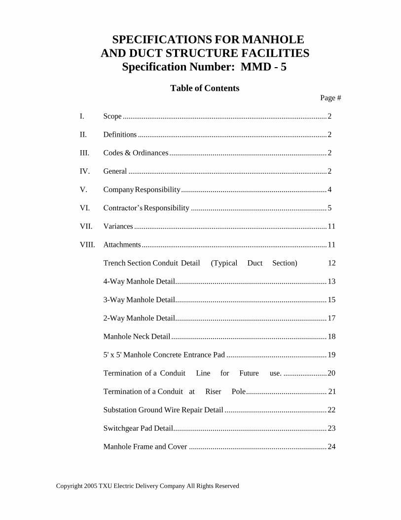
SPECIFICATIONS FOR MANHOLE
AND DUCT STRUCTURE FACILITIES
Specification Number: MMD - 5
Table of Contents Page #
I. Scope ............................................................................................................ 2
II. Definitions .................................................................................................... 2
III. Codes & Ordinances ................................................................................ 2
IV. General ......................................................................................................... 2
V. Company Responsibility .......................................................................... 4
VI. Contractor’s Responsibility ..................................................................... 5
VII. Variances ...................................................................................................... 11
VIII. Attachments .................................................................................................. 11
Trench Section Conduit Detail (Typical Duct Section) 12
4-Way Manhole Detail............................................................................. 13
3-Way Manhole Detail............................................................................. 15
2-Way Manhole Detail............................................................................. 17
Manhole Neck Detail ............................................................................... 18
5' x 5' Manhole Concrete Entrance Pad ................................................... 19
Termination of a Conduit Line for Future use. ....................... 20
Termination of a Conduit at Riser Pole ......................................... 21
Substation Ground Wire Repair Detail .................................................... 22
Switchgear Pad Detail.............................................................................. 23
Manhole Frame and Cover ...................................................................... 24
Copyright 2005 TXU Electric Delivery Company All Rights Reserved
TXU ELECTRIC DELIVERY SPECIFICATION: MMD - 5
February 2005 2
I. SCOPE
This document, when applied in conjunction with the construction drawing(s),
represents the minimum requirements and specification for TXU ELECTRIC
DELIVERY manhole and conduit systems. (duct structure)
II. DEFINITIONS
A. Company: TXU ELECTRIC DELIVERY and its designated representatives
B. Contractor: Individual or firm performing work for TXU ELECTRIC DELIVERY
III. CODES AND ORDINANCES
All applicable codes and ordinances shall be followed in the design and
construction of the manhole and conduit line system. Included, but not limited to,
are the following:
A. Local City Building Code
B. The National Electric Safety Code (NESC)
C. The contractor shall be familiar with and shall comply with all applicable
requirements of these specifications and with OSHA requirements. If there are
any conflicts or omissions, the OSHA requirements shall be met. Any conflict or
omission shall not relieve the contractor of responsibility of complying with
OSHA requirements.
D. Local City Location and Coordination Policy (if applicable)
E. The American Concrete Institute (ACI)
F. The American Society for Testing and Materials (ASTM)
G. Texas State Department of Highways and Public Transportation - Utility
Accommodation Policy
H. Local, city, state and federal environmental regulations.
IV. GENERAL
A. UTILITIES
1. The Contractor shall locate and protect all existing utilities, whether
indicated on the design drawings or discovered during the work. The
Contractor shall immediately notify the Company’s Authorized
Copyright 2005 TXU Electric Delivery Company All Rights Reserved
TXU ELECTRIC DELIVERY SPECIFICATION: MMD - 5
February 2005 3
Copyright 2005 TXU Electric Delivery Company All Rights Reserved
Representative when any utility not previously indicated or inaccurately
indicated on the design drawing is discovered.
2. The Contractor shall coordinate with the utility owner and shall allow
entrance, opportunity, and ample time for all utility relocations, extensions,
and modifications necessitated by the work.
B. DEWATERING -The Contractor shall remove all existing standing water located on
the work site. Furthermore, the Contractor shall maintain the work site, including
excavations, pits, and all other depressions, free from surface water.
1. Drainage
a. The Contractor shall stockpile all materials required for or resulting from
the work in a manner which will minimize the obstruction of the natural
flow.
b. When operations are interrupted by unfavorable weather conditions, the
Contractor shall prepare the work site to avoid ponding and erosion.
2. Clearing - No trees shall be cut or removed, except as directed by the
Company’s Authorized Representative. The Contractor shall use proper care
to prevent damage to trees which are to remain on site.
C. TRENCH SAFETY - The Contractor is responsible for obtaining and implementing
the trench safety program. Three copies of the trench safety specification (certified
by a registered professional engineer in the State of Texas) shall be supplied to TXU
ELECTRIC DELIVERY before construction begins.
D. CONSTRUCTION SCHEDULE - The Contractor shall supply a construction
schedule to TXU ELECTRIC DELIVERY before construction begins.
E. MATERIALS - This is a turnkey job. The Contractor shall supply all materials for
this job including manholes, necks, frames and covers, con-seal, ground rods, PVC
conduit, PVC bends, PVC couplings, tie-wraps, conduit spacers, PVC adhesive,
concrete, select backfill, pull ropes, pre-cast switchgear pads, etc., per TXU
ELECTRIC DELIVERY Specifications unless otherwise specified, in writing.
F. SURVEY - Unless otherwise noted the Contractor shall be responsible for providing

TXU ELECTRIC DELIVERY SPECIFICATION: MMD - 5
February 2005 4
Copyright 2005 TXU Electric Delivery Company All Rights Reserved
all surveying work needed to insure that the duct structure is constructed per the
design.
G. PERMITS - The Contractor is responsible for obtaining city permits (if allowed by
local authorities), and all construction shall be in accordance with city specifications
unless otherwise specified.
H. WORKING HOURS - Under normal working conditions, the placement of concrete
shall be done between the hours of 8:00 AM - 4:30 PM on weekdays. TXU
ELECTRIC DELIVERY inspector shall be notified a minimum of 2 hours prior to
the delivery of concrete and shall be present during placement.
I. STREET CLEAN-UP - The Contractor shall be responsible for cleaning paved
streets that have been soiled by their construction vehicles within 24 hours after
notification, by the appropriate governing authority or Company Representative.
J. RAMPS - The Contractor may need to install ramps to protect street curbs from
damage due to construction vehicle traffic.
K. TRAFFIC COORDINATION - Contractor shall have flag-men, road signs, etc. to
coordinate traffic around the job site per city or state requirements.
L. SPOILS - All unused spoils shall be hauled off the job site by the Contractor.
M. AS-BUILTS - Contractor shall supply TXU ELECTRIC DELIVERY one set of as-
built drawings upon completion of the job.
N. DESIGN CHANGES – Contractor shall submit a written request to the
appropriate TXU ELECTRIC DELIVERY Authorized Personnel prior to any
modification to the original design drawings that will change the number of bends
or add 10 percent or more to the overall conduit length found on the original design
plan. This written request must be provided prior to implementation of change.
V. COMPANY RESPONSIBILITY - The following shall be performed by and be the
responsibility of the Company:
A. The Company inspector is to inspect all manhole installations prior to the placing of
backfill and all conduit installations prior to the placement of concrete.

TXU ELECTRIC DELIVERY SPECIFICATION: MMD - 5
February 2005 5
Copyright 2005 TXU Electric Delivery Company All Rights Reserved
B. The Company inspector is responsible for coordinating all field changes with
Engineering.
C. All testing of concrete and backfill, which are deemed necessary by the Company,
shall be performed by a local testing laboratory at the Company’s expense.
VI. CONTRACTOR’S RESPONSIBILITY - The following shall be performed by and be
the responsibility of the Contractor:
A. The contractor shall notify TXU ELECTRIC DELIVERY Inspector a minimum of
24 hours before scheduling the pouring of concrete.
B. CONCRETE ENCASED DUCT STRUCTURE INSTALLATION
1. All conduit shall be concrete encased with a minimum of 3" of concrete.
The top conduits of any duct structure shall have a 3" or 6" minimum cover
depending on location site. Refer to construction drawings for duct section.
All concrete encasement shall have a pattern finish.
2. Concrete: 5 sack Portland Type I cement, 3/4" maximum size aggregate,
3000 PSI @ 28 days. The slump of the concrete may be increased by the
Contractor, with the approval by the Company inspector or approved TXU
ELECTRIC DELIVERY representative, in order to facilitate a wetter mix to
insure total encasement of the duct. However, the slump should not be
increased to the point where the ultimate yield strength of the concrete in
jeopardized.
3. Placement: All concrete shall be installed by the use of a hopper, trimmie,
chute, or pump truck unless otherwise specified by TXU ELECTRIC
DELIVERY inspector. At no time shall concrete be placed with a front-end
loader or any other similar type of machinery.
4. The duct structure shall be held down with screw-jacks (or by equivalent
means) at 20 ft. maximum intervals in order to prevent floating or racking of
the duct during placement of the concrete.

Copyright 2005 TXU Electric Delivery Company All Rights Reserved
TXU ELECTRIC DELIVERY SPECIFICATION: MMD - 5
February 2005 6
5. Conduit, bends, elbows and coupling: PVC conduit shall be minimum 6"
type DB, TC-6 DB-60/ASTM F-512, 90 degrees centigrade rated or greater
unless otherwise specified. All PVC 6” bends and elbows shall have a 36"
radius. See attached sketch for any deviation in conduit size.
6. Spacers: Carlon #288RLN (Base) and 289RLN (intermediate) or other TXU
ELECTRIC DELIVERY approved spacers shall be spaced at 5' intervals
(max). Spacers will be required and tied together with non-metallic tie-
wraps. Spacers shall also be used to “hold-down” the top row of ducts.
7. When complete, each conduit installed will be checked by pulling both a
mandrel and a swab through the entire length of conduit. A swab cannot
detect a break with a concrete buildup.
C. MANHOLE INSTALLATION
1. Manhole: Precast type, unless otherwise noted, should be supplied by
Brooks/Old Castle (or other approved supplier) and be octagonal shape, 3-
sections 15,000 lbs./section unless otherwise specified. (See attachment)
2. Preparation: 6 inches minimum pea gravel of cushion shall be installed in the
bottom of the excavated area prior to the manhole installation. Sand base
may be used with Project Manager’s approval.
3. Installation: A crane will be required to install all manholes, and it is the
Contractor’s responsibility to obtain the crane. Approved sealant is required
on all interfaces (supplied with manholes).
4. Backfill: Select backfill should be installed around manholes and compacted
to 95% minimum or flowable material shall be used as select backfill when
requested.
5. Entrance grade: The Contractor shall install the frame/cover and neck. TXU
ELECTRIC DELIVERY construction plans show the approximate entrance
elevation, however it is the Contractor’s responsibility to install the necessary
amount of neck to bring the top of the cover 2" above finished grade (or flush
with street grade when cover is in street). Saw cutting or grout-fill may be
required to obtain the appropriate entrance elevation.
Copyright 2005 TXU Electric Delivery Company All Rights Reserved
TXU ELECTRIC DELIVERY SPECIFICATION: MMD - 5
February 2005 7
6. The Contractor shall supply one (1) 8' x 5/8" copper clad ground rod, weld
type, in each manhole. Ground rod shall be vertically driven into undisturbed
soil. If rock is encountered, grounding shall be as directed by TXU
ELECTRIC DELIVERY inspector.
7. Concrete pad: The Contractor shall install a 5' x 5' x 6" concrete pad around
all manhole entrances in all non-paved areas. See attached drawing for
reinforced steel requirements.
D. BACKFILL AND COMPACTION
1. Top Soil: Existing top soil shall be replaced. Top soil shall be free of all
rock and clay.
2. Backfill: The backfill operation shall begin after the concrete has had time
to cure. The curing time is at the discretion of TXU ELECTRIC DELIVERY
inspector. The backfill shall have no rocks larger than 6".
3. Compaction: 95% minimum requirement
4. Lifts: 1 foot lifts (maximum)
5. Compaction Test: TXU ELECTRIC DELIVERY responsibility
6. Final Grade Elevation: The Contractor shall return the excavated area back
to the developer’s original grade elevation.
E. SUBSTATION FEEDER EXIT INSTALLATION - This covers the procedures
and materials to be used during site work at TXU ELECTRIC DELIVERY
substations or switching stations.
1. Company privileges - The Company’s Authorized Representative shall have
the right to test, at Company expense, all materials secured and work
performed.

Copyright 2005 TXU Electric Delivery Company All Rights Reserved
TXU ELECTRIC DELIVERY SPECIFICATION: MMD - 5
February 2005 8
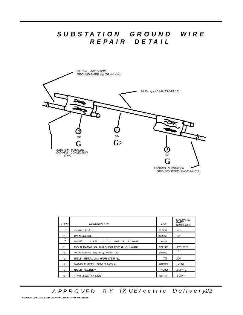
2. Substation Ground Repair - Substations generally have grounding systems
consisting of copper wires buried 1-3 feet beneath the surface which attach to
substation structures and perimeter fences. These ground grid wires may
exist at any location inside the substation to a few feet outside the substation
fence. If this ground grid wire is damaged, the CONTRACTOR shall notify
TXU ELECTRIC DELIVERY and repair the damage. Repair to damaged
ground grid wire shall be made to TXU ELECTRIC DELIVERY standards.
Most repairs to the ground grid wire may be made as shown on TXU
ELECTRIC DELIVERY drawing GNDREPAIR (See attachment p.22).
If the scope of the repair required to the substation grounding system is greater
than that shown on GNDREPAIR, contact TXU ELECTRIC DELIVERY.
3. The Contractor shall maintain access to the work site at all times.
4. Backfill - The Contractor shall backfill all excavations made during the
clearing and grubbing operations with compacted fill material. Fill
material, placement, and finishing shall comply with the provisions of
Section E-6 thru E-8 and as found on attachment (page 12) .
5. Excavating
a. The Contractor shall excavate to the contours, grades, and elevations
indicated on the grading plan.
b. Excavated materials, suitable for use as fill as determined by the
Company’s Authorized Representative, shall be placed in compliance
with the provisions of Section E-7 in fill or embankment areas indicated
on the grading plan.
c. The Contractor shall haul and dispose of all surplus excavated materials.
Disposal shall be away from the site, unless otherwise noted. The
Contractor shall meet the requirements of regulatory authorities regarding
proper disposal.
6. Fill Material
a. Excavated material, with prior approval by the Company’s Authorized
Representative, may be used as fill material.

Copyright 2005 TXU Electric Delivery Company All Rights Reserved
TXU ELECTRIC DELIVERY SPECIFICATION: MMD - 5
February 2005 9
b. Prior to hauling in fill material, the Contractor shall inform the
Company’s Authorized Representative of the location of the proposed fill
material so that samples may be obtained for required tests.
c. Soil suitable (per 6.b.) for use as fill material shall be free from organic
matter and deleterious substances and shall contain no rocks or stones
larger than one inch in diameter.
d. The soil shall be classified as sandy clays or clayey sands having a
Plasticity Index (PI) greater than 4 and less than 12 and a Liquid Limit
(LL) less than 30. The Company shall pay for a maximum of two series
of the above tests. Any additional tests required by failure of the material
to meet the requirements shall be performed at the expense of the
Contractor.
e. If the tests performed on the proposed fill material yield satisfactory
results, the fill material shall then be tested in accordance with
“Maximum Density-Optimum Moisture Test” ASTM-D698 (Standard
Proctor Test), and the results used in compaction.
7. Filling
a. The Contractor shall fill to the contours, grades, and elevations indicated
on the grading plan.
b. Fill material shall be placed in lifts not exceeding 12 inches in
uncompacted thickness, sprinkled, rolled, and compacted to a minimum
of 90% of maximum dry density as determined by ASTM D-698.
c. Water necessary to obtain proper moisture content for compaction shall
be furnished by the Contractor.

Copyright 2005 TXU Electric Delivery Company All Rights Reserved
TXU ELECTRIC DELIVERY SPECIFICATION: MMD - 5
February 2005 10
8. Finish Grading
a. The Contractor shall fill to the contours, grades, and elevations
indicated on the grading plan.
b. The Contractor shall correct all imperfections, discovered during
finish grading, by scarifying the area affected, adding or removing
material as required, reshaping, and recompacting.
c. The Contractor shall not apply yard covering until the subgrade has
been approved by the Company’s Authorized Representative.
9. Yard Covering (crushed limestone) - The crushed limestone shall conform to
Texas State Department of Highways and Public Transportation’s 1982 Standard
Specifications for Construction of Highways, Streets and Bridges, Item 248.
10. Application of Yard Covering
a. The Contractor shall apply, to all areas indicated on the grading plan,
sufficient yard covering to obtain a minimum of four inches after
compaction.
b. Yard covering shall be compacted to a minimum of 90% of maximum
dry density as determined by ASTM D-698.
c. Under no circumstances shall the Contractor add thin layers of fine
materials to yard covering in order to meet the final grade.
11. Application of Base Material (Roads and Parking Areas)
a. The Contractor shall, unless otherwise noted, supply base material which
complies with the provisions of Section E-9.

Copyright 2005 TXU Electric Delivery Company All Rights Reserved
TXU ELECTRIC DELIVERY SPECIFICATION: MMD - 5
February 2005 11
b. The Contractor shall apply, on all limestone roads and parking areas,
sufficient base material to obtain a minimum of six inches after
compaction.
c. Base material shall be compacted to a minimum of 95% of maximum
dry density as determined by ASTM D-698.
b. Under no circumstances shall the Contractor add thin layers of fine
materials to base material in order to meet final grade.
12. Final Grading (Roads and Parking Areas)
a. The final grading shall provide smooth and uniform surfacing and shall
be approved by the Company’s Authorized Representative.
b. The Contractor shall correct all imperfections discovered during final
grading by scarifying the area affected, adding or removing material
as required, reshaping, and recompacting.
VII. VARIANCES
A. Variances to these specifications shall be submitted in writing to and approved by
the Company prior to construction.
B. Any approved variance shall apply only to the particular project for which it was
submitted.
VIII. ATTACHMENTS

.
T Y P I C A L D U C T S E C T I O N
r- 24" ---,
r- 24" -----,
MIN
2£6 30" MIN
" • o . 0'. . o
·:· ·-- · · ·:: • - .
0 0 - 0
12"
o .o o
. :.. • · +
i-- 24" --- i
r- 24" I
8£6
·._.. o· ·:o· · ·· :·. 'o • D •
- • - 0 '
·;:o·.:_ o·- :_ :o.-·o:_·; :..-..-·o·::. ····· :.: . .
• 0 • • • • 0 :
• • 0 • • 0 • •
30" MIN
42"
A P P R O V E D B Y TX U E / e c t r i c D e l i v e r y 1 2 COl'YRIGHT 2005 1XU ELECTRIC DELIVERY COMPANY All. RIGHTS RESEMD
6£6 30" MIN
30"
4£6
•

4 W A Y M A N H O L E - - - - - - - -
'-------143 ...
48 ... __. 32" _.. 48...
7" 3 ll'v'M
48 *"
143 ... u
32" '
G)
PLASTIC
SUMP
--' --'
1" PCV SLEEVE 48...
IN FLOOR (TYP.)
7" WALL A
PLAN VIEW
36" DIA. OPENING IN!
GROOVE (NECK EXTENSIONS
AS SPECIFIED BY CUSTOMER.)
A P P R O V E D B Y TX U E ! e c t r i c D e l i v e r y 7 3

4 W A Y M A N H O L E
A P P R O V E D COl'YRIGHT 2005 1XU ELECTRIC DELIVERY COMPANY All. RIGHTS RESEMD
B Y TX U E / e c t r i c D e l i v e r y 1 4
I
T - i"'--- L
9"
15"
102" 54" 33"
L 15" 10 ••
PLASTIC COATED
PULLING IRON
8 •• 8 ••
8 - 6" TERMINATORS
3" SEPARATION B1W.
I ., r'
15" -r - 1 t
- 7" 1--
11¢::::::::::1::====;1;3;::•:";;;:::::::====l:r1
I + t + T 102" 54" l + + +...._ S" TYP. -..............
+ +14" + I'---..r.... 9 - RACKING {TYP.J I-
1 INSERTS.'"
15" I
I ..........
i- -68 •.
WALLS B. D. F & H
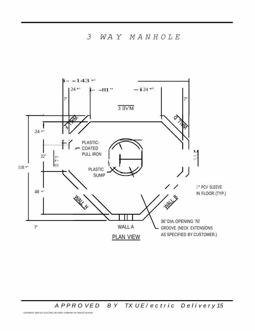
3 W A Y M A N H O L E
A P P R O V E D COl'YRIGHT 2005 1XU ELECTRIC DELIVERY COMPANY All. RIGHTS RESEMD
B Y TX U E / e c t r i c D e l i v e r y 15
i- -----143 *"
24 *" i- --81"
---i 24 *"
7" 7"
3 ll'v'M
24 *"
32" r- r-
PLASTIC-
COATED
PULL IRON
u --' --'
118 *" Cl
PLASTIC
SUMP
1" PCV SLEEVE 48 *" IN FLOOR (TYP.)
7" WALL A
PLAN VIEW
36" DIA. OPENING 'NI
GROOVE (NECK EXTENSIONS
AS SPECIFIED BY CUSTOMER.)

3 W A Y M A N H O L E
A P P R O V E D COl'YRIGHT 2005 1XU ELECTRIC DELIVERY COMPANY All. RIGHTS RESEMD
B Y TX U E / e c t r i c D e l i v e r y 16
00 - 00 -
-
I ' "'-. -
'
RING & COVER
036" NECK EXTENSIONS AS SPECIFIED AS REQUIRED
I I 9"
15" I !
I 13 *"
102" 54"
..........
00 -i:: 9"
L..... 9"
i::
"' 13 *"
9"
00
15"
I 9" II , _
"\. II
I 11 *" - 11 *H "-8 - 6" TERMINATORS
-32" - 3" SEPARATION B1W.
WALL A
036" NECK EXTENSIONS
AS REQUIRED
9"
15"
RING & COVER
AS SPECIFIED
I

3 W A Y M A N H O L E
A P P R O V E D COl'YRIGHT 2005 1XU ELECTRIC DELIVERY COMPANY All. RIGHTS RESEMD
B Y TX U E / e c t r i c D e l i v e r y 17
11 *" 8 - 6"" TERM.
3" SEPARATION
PLASTIC COATED
PULLING IRON

A P P R O V E D COl'YRIGHT 2005 1XU ELECTRIC DELIVERY COMPANY All. RIGHTS RESEMD
B Y TX U E / e c t r i c D e l i v e r y 18
24"
143"
81" 24"
7" 7"
)"
24 ••
95"
32" ! 24 ••
7" mi....e.
t-== =
I
2 W A Y M A N H O L E
36" DIA. OPENING
W'GROOVE FOR
NECK EXTENSIONS
1" PCV SLEEVE
IN FLOOR, 6"
FROM WALL
PLASTIC
SUMP PLAN VIEW
I I 9" • • •
I I
42" - -
=-
42" - -
9" - II
I WALL A 6" j -

A P P R O V E D COl'YRIGHT 2005 1XU ELECTRIC DELIVERY COMPANY All. RIGHTS RESEMD
B Y TX U E / e c t r i c D e l i v e r y 1 s
M A N H O L E N E C K
TOP VIEW
SIDE VIEW
\ I - - - - - - - , 1
6",12",18", 24",AND 36"
SECTIONS
I I
\ I
36" l.D.
48" 0.0.
A P P R O V E D COl'YRIGHT 2005 1XU ELECTRIC DELIVERY COMPANY All. RIGHTS RESEMD
B Y TX U E / e c t r i c D e l i v e r y 1 9
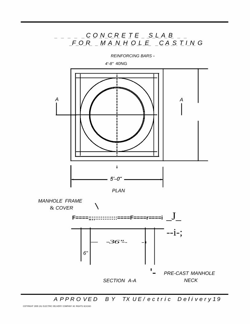
-- -36''-- -i
6"
C O N C R E T E S L A B
F O R M A N H O L E C A S T I N G
- - - - - - - - - - - - - - - - - - - - - -
- - - - - - - - - - - - - - - - - - - - - -
REINFORCING BARS -
4'-8" 40NG
PLAN
MANHOLE FRAME
& COVER
F====;;;;::::::::::::====F====r====i _J_
--i-;
SECTION A-A
'- PRE-CAST MANHOLE
NECK
A A

A P P R O V E D B Y COl'YRIGHT 2005 1XU ELECTRIC DELIVERY COMPANY All. RIGHTS RESER.VED
TX U E / e c t r i c D e l i v e r y 2 0
- - - - - - - - -
F O R F U T U R E U S E
T E R M I N A T I O N O F C O N D U I T
L I N E
- - -
- - - - - - - - - - -
STAJR STEPPED COLD JOINT WITH ELECTRONIC CONDUrT MARKER
INSTALL ECM
CONDUITS
L EACH COND:TO BE
CAPPED. TENCH BACKFILLED WITH SELECT FILL
El FCTRONIC CQNDlllT MARKER fECMI
1. CONTRACTOR, UNLESS OTHERWISE NOTED IS RESPONSIBLE FOR
OBTAINING AND INSTALLING THE ECM.
2. CONSULT 1XU ELECTRIC REPRESEBTATIVE FOR APPROVED ECM.
3. ECM SHALL BE BURIED DIRECTLY OVER AND A MIN. OF 6" ABOVE
DUCT INSTALLATION AND NO MORE THAN 6'BELOW FINAL GRADE.
4. ECM SHALL BE INSTALLED FLAT AND LEVEL. SEE PLAN SHEETS FOR
LOCATION.
5. ECM SHALL BE COVERED WITH 4" OF FIRM SOIL TO PREVENT
MOVEMENT OR DAMAGE DURING BACKFILL.
/NCQMP! ETf QUCT IWF
1. ON ALL INCOMPLETE DUCT LINES (DUCTS THAT ARE TO BE EXfENDED
AT A FUTURE TIME). THE CONDUITS ARE TO BE WATERTIGHT WITH
A CONDUIT CAP SOLVENT CEMENTED INTO PALCE.
2. DOWELLING IS THE METHOD TO BE USED IN ORDER TO JOIN NEW
DUCT TO EXISTING UNFINISHED DUCT. INSTALL #5 DOWELL WITH
B INCHES MINIMUM EMBEDMENT.

A P P R O V E D B Y COl'YRIGHT 2005 1XU ELECTRIC DELIVERY COMPANY All. RIGHTS RESEMD
TX U E / e c t r i c D e l i v e r y21
T E R M I N A T I O N
C O N D U I T A T R I S E R
O F
- - -
- - - - - - - - - - -
- - - - - - - - - - - - - - - -
- - -
P O L E
i
I
EXTEND 6" G.I. OR PVC SCH 80 CONDUIT UP INDICA1ED OTR. OF
TERMINAL POLE TO A HEIGHT OF 10'-r.
FINISH GRADE
30" MINIMUM DEPTH
ENCASEMENI
INSTALLATION
AROUND CONDUfTS
SEE PLAN VIEW
CAP 1-6" SPARE
CONDUIT FOR
FUTIJRE USE
2-6" PVC CONDUfTS
u•oo NOT BEND CONCRETE TO POLE".,.
1-6" CONDUIT UP POLE
1-6" CONDUIT
TO BE CAPPED
"CONCRETE
ENCASEMENJ
FOR FUTURE USE
A P P R O V E D B Y COl'YRIGHT 2005 1XU ELECTRIC DELIVERY COMPANY All. RIGHTS RESEMD
TX U E / e c t r i c D e l i v e r y22
S U B S T A T I O N G R O U N D
- - - - - - - - - -
R E P A I R
- - - - - -
D E T A I L W I R E
EXISTING SUBSTATION GROUND WIRE (2{) OR 4-0 CU.)
NEW 2{) OR 4-0 CU. SPLICE
OR OR
G G> PARALLEL THROUGH CADWELL CONNECTION
(TYP.) OR
G EXISTING SUBSTATION
GROUND WIRE (2{) OR 4-0 CU.)
ITEM
DESCRIPTION
TSN
CADWELD PART NUMBERED
1
IAJIDL '>ll rl I onooco UM
2 WIRE 4-0 CU. 303253 1'W>.
·' AA'l"ll n ' A ' I Cl • • • •• CrlD "Jll r'I I LA/IDC
ooom
4 MOLD PARALLEL THROUGH FOR MJ CU. WIRE 322112
PTC-2020
fi llllCI n 11.Ai::TJ\I 11i:;: /Cf1Q /Tt:'ll.A' 3J
000001 ""
6 WELD METAL 2nn fFOR ITEM 31 "'2 200
7 HANDLE /FITS ITEM 3 AND 4l 287995 L-160
Q Mr1LD rLEANER '"'212 B-1""' ..
9 FLINT IGNITOR GUN 386189 T-320
COl'YRIGHT 2005 1XU ELECTRIC DELIVERY COMPANY All. RIGHTS RESEMD
S W I T C H G E A R P A D D E T A I L
PLAN
NOTES:
1. INSTALL 14" MINIMUM SMALL TO MEDIUM GRAVEL BASE. INCLUDE MINIMUM 12" GRAVEL FILL AROUND SIDES.
2. FOR CLEARANCES ON ALL SIDES OF THE SWITCHGEAR SEE REFERENCE DRAWING 202-100.
3. EACH PAD WILL INCLUDE FOUR - LIFTING POINTS RATED AT 2000 LBS EACH.
4. WHEN INSTALLING SPARE CONDUIT, CENTER DIMENSION LINES BETWEEN CONDUITS.
5. CONDUIT NOT TO EXTEND MORE THAN 3" ABOVE BOTTOM OF DEEPWELL.
A P P R O V E D B Y TX U E / e c t r i c D e l i v e r y 2 3
LIFTING POINTS
NOTE 3
INCHES A B C D E E2 F G G2 W X
25KV 100 76 62 86 40 18 48 44 16 68 14
G2 G
BACK
G2 15KV 84 60 50 74 30 15 36 38 11 52 14
- -i - - - - - - ' I 12"
I
I!
I
I
I
1'f ' I X
3" w
NOTE 4
ai
A
t. I
E2
w -d3
E E21
! I
I
I
I
I
I
µ
F c D
..,. .. A
I_ _
J •
"""13.. 12"
FRONT
,,.. SECTION " A -
A" FRONT B
A
12"
COl'YRIGHT 2005 1XU ELECTRIC DELIVERY COMPANY All. RIGHTS RESEMD
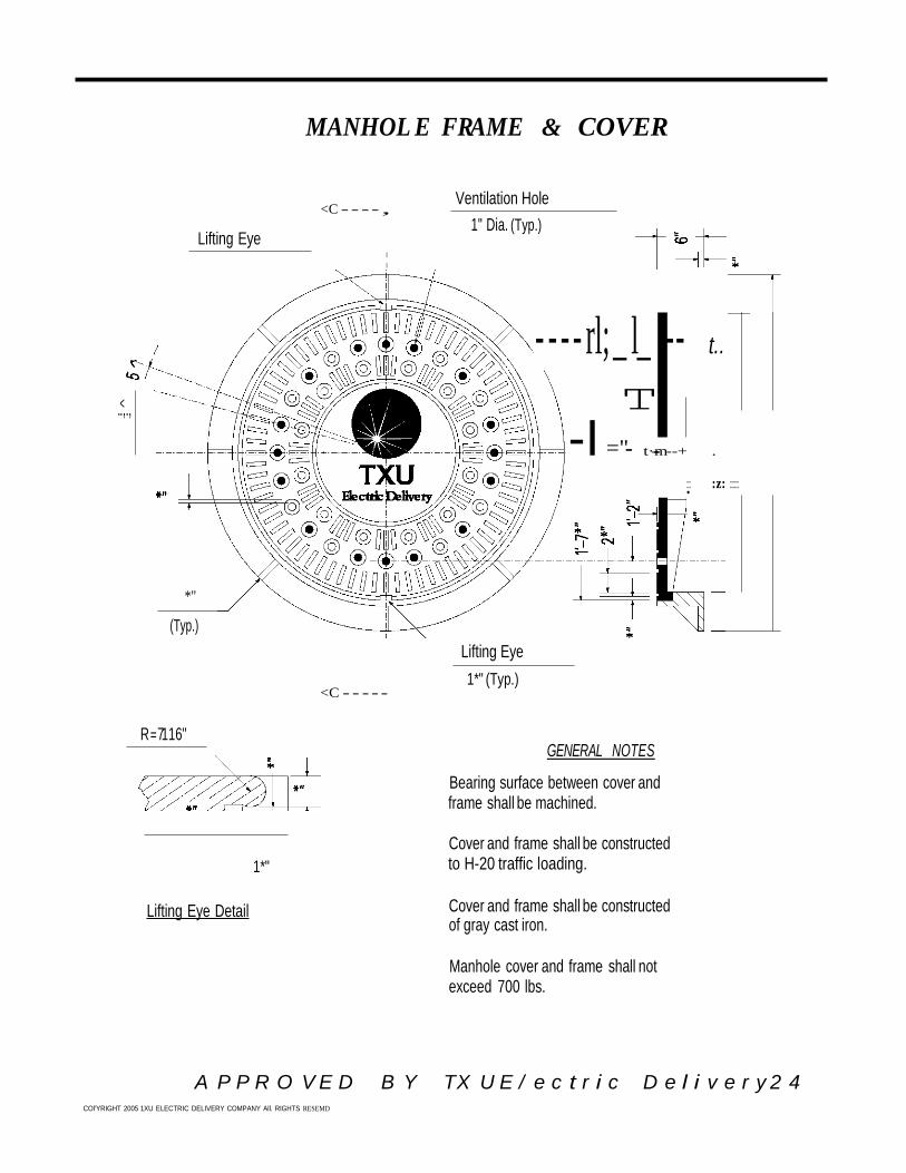
MANHOL E FRAME & COVER
.<.,.,
Lifting Eye
<C - - - - ,
I
I
Ventilation Hole
1" Dia. (Typ.)
- - - - rl;_ l_ -- t..
T
-I ="- t·---m- --+ .
-:::: :z: ::::
*"
(Typ.)
<C - - - - -
Lifting Eye
1*" (Typ.)
R =7116"
1*"
GENERAL NOTES
Bearing surface between cover and frame shall be machined.
Cover and frame shall be constructed to H-20 traffic loading.
Lifting Eye Detail Cover and frame shall be constructed of gray cast iron.
Manhole cover and frame shall not exceed 700 lbs.
A P P R O V E D B Y TX U E / e c t r i c D e l i v e r y 2 4