speech intelligibility measurements in practice - … stip… · · 2016-09-01speech...
TRANSCRIPT

Speech intelligibility measurements in practice Obtaining accurate and reliable data using STIPA tools Embedded Acoustics White Paper EA-WP-2014-199-1 November 2014

Embedded Acoustics white paper EA-WP-2014-99-1
2
Title Speech intelligibility measurements in practice; Obtaining accurate and reliable data using STIPA tools Report number EA-WP-2014-199-1
Authors Dr. Sander J. van Wijngaarden Jan A. Verhave Email: [email protected]
Embedded Acoustics BV Molengraaffsingel 12 2629 JD Delft The Netherlands T:+31 88 8770700 www.embeddedacoustics.com
Date November 2014
Classification -
© 2014 Embedded Acoustics BV
Dit rapport is auteursrechtelijk beschermd. Het is niet toegestaan dit rapport geheel of gedeeltelijk te kopiëren of op enigerlei wijze openbaar te maken, te verspreiden of te verveelvoudigen zonder voorafgaande schriftelijke toestemming van Embedded Acoustics BV.
All material in this report is, unless otherwise stated, the property of Embedded Acoustics BV. Copyright and other intellectual property laws protect these materials. Reproduction or retransmission of the materials, in whole or in part, in any manner, without the prior written consent of the copyright holder, is a violation of copyright law.
Embedded Acoustics white paper EA-WP-2014-99-1
3
1. Introduction
Measuring speech intelligibility using the STIPA method is not particularly difficult. With the proper tools and a minimal amount of practice, measurement results are quickly obtained that are the most accurate among all intelligibility test methods. That being said: there are a number of pitfalls to be aware of, and mistakes that undermine the validity of measurements do occur – not just with not first-time users. There is an abundance of papers and other information resources concerning the Speech Transmission Index available [1,2], but almost all of this is intended for developers and expert-level users. We admit that this is especially the case with the papers and books published by us (the authors of this white paper). This is our effort to fix this omission, and provide a tutorial that covers (only) the basics of STIPA testing. If some of the steps we are describing here seem trivial, we apologize for this in advance. For the purposes of this white paper, we prefer repeatedly stating the obvious over forgetting crucial steps.
In the next section, we will start by definining what STIPA is, and how it is used to measure speech intelligibility. In section 3, we will provide an overview of the tools you need for doing STIPA measurements. Section 4 continues by suggesting a generic set of “standard operation procedures” to adopt for STIPA measurements, followed in section 5 by specific details on the procedures to be followed for NFPA72 Annex D. In section 6, limitations of the STIPA method are described, followed by a few more advanced processing options in section 7.
This paper covers the basics of STIPA testing. For information on the physics and mathematics underlying the Speech Transmission Index, please refer to the publications cited in the list references included with this paper, in particular the book “Past, Present and Future of the Speech Transmission Index.” This book is available for download, free of charge, from the Embedded Acoustics website: www.embeddedacoustics.com [2]
2. What exactly is STIPA, and how does it work?
STIPA stands for “Speech Transmision Index for Public Address systems.” It is a specific implementation of the Speech Transmission Index model invented by Steeneken and Houtgast in the late 1970’s [3].
STIPA is an objective method for measuring speech intelligibility, using a specific test signal (the STIPA signal) in combination with a specific, dedicated acoustic measuring instrument (the STIPA analyzer)
In theory, there are several variants of the Speech Transmission Index to be chosen from, tailored for different applications[1]. In practice, STIPA has almost completely replaced all other STI variants, simply because it performs equal or better compared to these other variants, and usually STIPA measurements take considerably less measurement time [4]. Although it appears that STIPA is becoming in synonym to Speech Transmission Index, it is good to be aware that STIPA has its limitations, even if these are rarely encountered in practice. The limitations are addressed in section 6 of this paper.
Older Speech Transmission Index variants that are still specified by some standards are STITEL and RASTI. These are now obsolete and replaced by STIPA. When the Speech Transmission Index is specified (without further reference to any specific test signal or variant), please refer to section 6 of this paper to decide whether it is safe to use STIPA. Usually it is, but not always.
Each STIPA measurement takes 25 seconds and results in a single value between 0 and 1: the Speech Transmission Index. In written reports the correct way to refer to results from STIPA measurements is as Speech Transmission Index (or STI) values, and not as STIPA values. STIPA is the method you use to obtain STI results.

Embedded Acoustics white paper EA-WP-2014-99-1
4
2.1. STIPA characterizes speech transmission channels Although it is nowadays generally accepted to loosely refer to STIPA measurements as “speech intelligibility measurements,” this is not literally correct. The Speech Transmission Index reflects how a transmission path affects speech intelligibility; it is a purely physical measure that does not take listeners and talkers into account, but it just characterizes the transmission channel. This means that factors such as hearing loss, poor articulation and other (human) limitations are not taken into account. In practice, this is usually a good thing. If you are the supplier of a PA system that is being certified using STIPA, you do not have to worry about the sloppy speech style or the impaired hearing of the evaluators (or other factors out of your control) to affect the outcome of the tests. Standards usually set performance limits based on the STI under the (often implicit) assumption that all talkers and listeners are “normal.” This has one potential drawback: it means that expectations based on STIPA measurements may be too optimistic if, in practice, large populations of hearing impaired people need to be addressed, or announcements are made in an accented voice or with a sloppy speech style. In those cases, performance limits need to be set to higher STI values to guarantee sufficient intelligibility. In other words: STIPA measurements tell you only what the speech transmission channel does to the speech in terms of intelligibility. Before anything else, you need to consider what the speech transmission channel you intend to test comprises. The term speech transmission channel in the context of STIPA testing is used in a broader sense then (for instance) in telecommunications engineering. The term “channel” suggests to some that electronic equipment (e.g. for radio transmission) is used, which is not necessarily the case. Figure 1 shows the definition of the speech transmission channel: basically everything that influences intelligibility, except to the talkers and listeners themselves.
Figure 1. Schematic representation of the definition of a speech transmission channel. The channel comprises
everything between the talker and listener that influences intelligibility, including noise sources and the acoustics of the environment, except for the talker and listener themselves.
In fig. 1, the fan symbolizes a noise source interfering with speech from the talker. The talker and listener are occupying the same space, the acoustic properties of which (determined by wall materials, ceilings, etc.) will have an influence on intelligibility. This is also taken into account by the STI. The bullhorn used by the talker represents the use of electro-acoustic devices. Such devices, if present in the transmission channels, may introduce non-linear distortion components which are also taken into account by the STI.
Transmission channels tested with STIPA may include combinations of any of the following factors that influence intelligibility: ambient noise, room acoustics (reverberation), electronic noise, non-linear distortion, amplification, filtering (modifying the frequency transfer function). Explicitly NOT included in the test results are all factors related to the talkers and listeners themselves (accent, hearing loss, etc.)
talker listener
speech transmission channel

Embedded Acoustics white paper EA-WP-2014-99-1
5
2.2. Speech intelligibility versus speech quality
Speech intelligibility is a measure of the effectiveness of speech communication. Speech intelligibility is usually defined as the percentage of speech units (syllables, words or sentences) correctly perceived by listeners. Formal speech intelligibility measurements are usually done with panels of listeners and calibrated speech signals. In a tightly controlled test setup, participants (listeners) repeat back exactly what they hear. This is compared to the source material to precisely compute the percentage perceived correctly. If done properly, these subjective tests are by far the most accurate way to measure intelligibility, because no assumptions are made at all: speech intelligibility is measured directly according to its definition. Even so, subjective intelligibility tests are hardly ever done these days, simply because the equivalent of a 25-second STIPA test would involve at least 2 subject-hours of listening tests, and about 30 minutes of recording speech samples from the channel under test. Whereas a STIPA test instantly shows the results (the STI value), a subjective test has to be completed before the final results are known – which usually takes a few weeks.
Perhaps the most common misconception about speech intelligibility is that a trained listener can judge speech intelligibility by simply listening to a few sentences. No accurate statements about speech intelligibility can be made by just listening to random speech materials for a few minutes. It is, of course, possible to get an impression of how severely the speech is degraded – but this does not immediately tell you the effect on speech intelligibility.
It is impossible to listen to speech without forming an opinion on the quality of the speech signal. It is important to keep in mind that speech quality (“how good does it sound?”) and speech intelligibility (“how much can I understand?”) are not the same measures. The distinction is not just academic. Nearly all forms of non-linear degradation, such as peak clipping, have a severe adverse effect on speech quality, whereas speech intelligibility sometimes even increases!
Obtaining a reliable subjective impressions of speech intelligibility in the field, independently from STI tests, is usually not at all feasible. Keep in mind that subjects memorize words quickly, and word lists can therefore never be re-used. This effect is much worse still with sentences, which are really not suitable for evaluation speech intelligibility in the field.
Remarks made about speech intelligibility based on personal observations should really be interpreted as opinions on speech quality.
2.3. How does it work? Why is the STIPA test signal representative of speech? Now that we have defined what a transmission channel is, and that we have established the difference between speech intelligibility and speech quality, the next question to address is: how is STIPA used to measure how a speech transmission channel affects speech intelligibility?
To perform any STIPA test, the following three steps are taken:
• Replace the (human) talker by a source of the STIPA test signal. Natural speech cannot generally be used for the test; it has to be the STIPA signal. This needs to be introduced in the same way as the natural, human speech would be (e.g., using the same microphone, at the same distance, etc.)
• Make sure that the transmission channel is controlled and stable, and representative of the scenario you wish to test. For instance: to test the PA system in a mall, make sure that the PA system is functioning as it normally would, with the settings you consider to be representative of normal operation, and with a representative level of background noise.
• “Replace” the human listener by the microphone of the STIPA analyzer. In practice, the STIPA analyzer is usually moved around the test venue to obtain readings at multiple locations. Since a single measurement takes only 25 seconds, it is not uncommon to do multiple measurements at each location (to be able to analyze the statistics later on), and to perform up to hundreds of individual measurements for a single venue.
Embedded Acoustics white paper EA-WP-2014-99-1
6
The STIPA signal is a noisy signal that contains all frequencies present in human speech, from approx. 80 Hz to 11 kHz. A common misconception, caused age-old conventions in telecommunications engineering, is that human speech is limited to the range between 300 and 3400 Hz. The actual range is much wider, and the entire range is taken into account. The STIPA signal sounds nothing like speech. Yet similar to speech, it features modulations (intensity fluctuations) in the range from 0.6 to 12.5 Hz. In real speech, intensity fluctuations form the main mode used to encode information. Loss of these modulations means loss of information. This is how the STI works: the loss of these modulations is measured. Instead of pseudo-random fluctuation patterns, deterministic patterns are used that make it easy for the analyser to measure the modulation depth. For STIPA, two modulation frequencies are considered per octave band.
In real speech, information is encoded through intensity fluctuations. Loss of modulation depth means loss of information, which translates into a reduction of speech intelligibility. This is how the STI works: the artificial test signal (STIPA) has a carefully designed pattern of modulation frequencies. The STIPA analyzer measured how the transmission channel has reduced the modulation depth. This is measured in multiple frequency bands (125 Hz – 8 kHz), across a range of modulation frequencies (0.6 – 12.5 Hz).
2.4. Interpreting STIPA values. The Speech Transmission Index is a single-number rating in the range between 0.00 and 1.00. Obviously, zero corresponds to not intelligibility at all; a value of 1.00 means perfect intelligibility. Note that even at an STI of 1.00, speech quality may be perceived as far from perfect. The question is: how do we interpret the scale between 0 and 1? The original inventors of the STI, Steeneken and Houtgast [3], introduced the following table to translate the STI values into meaningful categories. Table 1. STI category labels
STI category label STI range bad 0.00 – 0.29 poor 0.30 – 0.44 fair 0.45 – 0.59 good 0.60 – 0.74 excellent 0.75 – 1.00
Application standards introduce acceptance limits based on the above table. Mininum values commonly required by application standards are 0.45 and 0.50. In practice, any transmission channel that shows STI values below 0.35 is not fit for any kind of use. What limit is appropriate depends on the type of use to which the speech transmission channel will be applied. Performance limits are usually raised if large proportions of the listener population are expected to be hearing impaired or non-native listeners. STI values always rounded to two decimals. The uncertainty associated with a single STIPA measurement is 0.02 to 0.03. A higher accuracy can be achieved by taking the average across multiple measurements. 2.5. Examples of different types speech transmission channels to be tested with STIPA The most common application of the STIPA test method is to evaluate PA systems – hence the “PA” in STIPA. Below, we present a few common STIPA testing scenarios, for which we explicitly define what the transmission channel to be tested is, what we consider to be our talkers and listeners, and what factors we expact to be of influence on the STI. Keep in mind that during STIPA tests all talkers will be replaced by a source of the STIPA test signal and a listeners (and listener locations) will be measuring positions where the STIPA analyser will be used.
Embedded Acoustics white paper EA-WP-2014-99-1
7
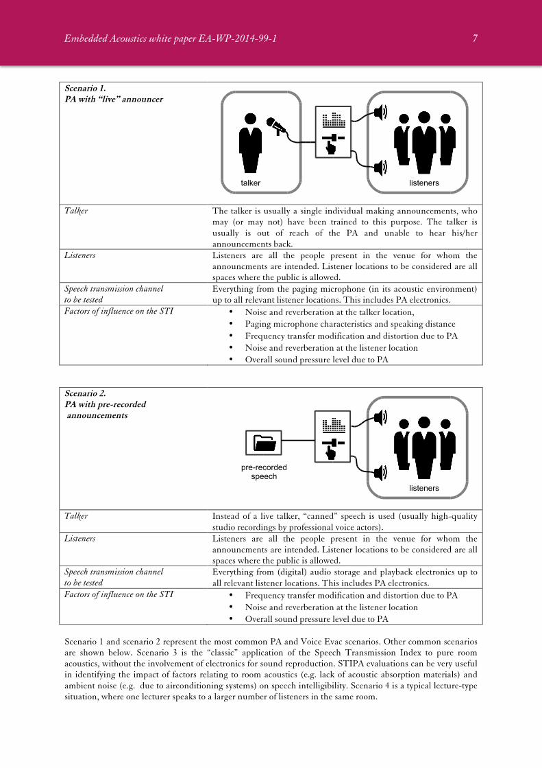
Scenario 1. PA with “live” announcer
Talker The talker is usually a single individual making announcements, who
may (or may not) have been trained to this purpose. The talker is usually is out of reach of the PA and unable to hear his/her announcements back.
Listeners Listeners are all the people present in the venue for whom the announcments are intended. Listener locations to be considered are all spaces where the public is allowed.
Speech transmission channel to be tested
Everything from the paging microphone (in its acoustic environment) up to all relevant listener locations. This includes PA electronics.
Factors of influence on the STI • Noise and reverberation at the talker location, • Paging microphone characteristics and speaking distance • Frequency transfer modification and distortion due to PA • Noise and reverberation at the listener location • Overall sound pressure level due to PA
Scenario 2. PA with pre-recorded announcements
Talker Instead of a live talker, “canned” speech is used (usually high-quality
studio recordings by professional voice actors). Listeners Listeners are all the people present in the venue for whom the
announcments are intended. Listener locations to be considered are all spaces where the public is allowed.
Speech transmission channel to be tested
Everything from (digital) audio storage and playback electronics up to all relevant listener locations. This includes PA electronics.
Factors of influence on the STI • Frequency transfer modification and distortion due to PA • Noise and reverberation at the listener location • Overall sound pressure level due to PA
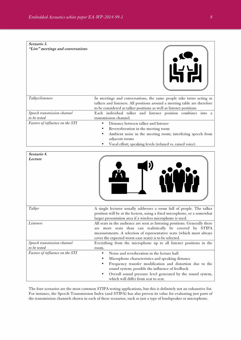
Scenario 1 and scenario 2 represent the most common PA and Voice Evac scenarios. Other common scenarios are shown below. Scenario 3 is the “classic” application of the Speech Transmission Index to pure room acoustics, without the involvement of electronics for sound reproduction. STIPA evaluations can be very useful in identifying the impact of factors relating to room acoustics (e.g. lack of acoustic absorption materials) and ambient noise (e.g. due to airconditioning systems) on speech intelligibility. Scenario 4 is a typical lecture-type situation, where one lecturer speaks to a larger number of listeners in the same room.
talker listeners
pre-recordedspeech
listeners
Embedded Acoustics white paper EA-WP-2014-99-1
8
Scenario 3. “Live” meetings and conversations
Talker/listeners In meetings and conversations, the same people take turns acting as
talkers and listeners. All positions around a meeting table are therefore to be considered as talker positions as well as listener positions
Speech transmission channel to be tested
Each individual talker and listener position combines into a transmission channel.
Factors of influence on the STI • Distance between talker and listener • Revererberation in the meeting room • Ambient noise in the meeting room; interfering speech from
adjacent rooms • Vocal effort; speaking levels (relaxed vs. raised voice)
Scenario 4. Lecture
Talker A single lecturer usually addresses a room full of people. The talker
position will be at the lectern, using a fixed microphone, or a somewhat larger presentation area if a wireless microphone is used.
Listeners All seats in the audience are seen as listening positions. Generally there are more seats than can realistically be covered by STIPA measurements. A selection of representative seats (which must always cover the expected worst-case seats) is to be selected.
Speech transmission channel to be tested
Everything from the microphone up to all listener positions in the room.
Factors of influence on the STI • Noise and reverberation in the lecture hall • Microphone characteristics and speaking distance • Frequency transfer modification and distortion due to the
sound system; possible the influence of feedback • Overall sound pressure level generated by the sound system,
which will differ from seat to seat. The four scenarios are the most common STIPA testing applications, but this is definitely not an exhaustive list. For instance, the Speech Transmission Index (and STIPA) has also proven its value for evaluating just parts of the transmission channels shown in each of these scenarios, such as just a type of loudspeaker or microphone.

Embedded Acoustics white paper EA-WP-2014-99-1
9
3. Equipment and resources needed for a STIPA measurement 3.1. Availability of the transmission channel To be able to do a STIPA test, first of all you need to have access to the transmission channel you aim to evaluate. This is not always as easy as it sounds, since you will probably be playing back STIPA test signals at high sound levels for several hours. For a PA system in mall (which is the example we used before, and which corresponds to scenarios 1 and 2), performing tests during opening hours is usually not an option. STIPA signals are not pleasant to listen to. Measurements will therefore have to take place after hours, when the mall is empty. However, the level of background noise, which is largely dependent on the number of people in the mall, will not be realistic. In other words: you don’t have access to the transmission channel under realistic conditions. There is a common workaround for this problem, which comes down to measuring the background noise during the day, and measuring STIPA at night. The background noise is then computationally taken into account in the STI calculation. This procedure is explained in section 7 of this paper. 3.2. STIPA test signal source It is not possible to do STIPA measurements without a source of the STIPA test signal.
STIPA tests can only be done based on the STIPA test signal compliant to IEC060268-16 rev. 3 or higher [5]. Natural speech or other test signals cannot be used.
STIPA signals compliant to the IEC-standard are available from all manufacturers of STIPA measurings solutions. The Embedded Acoustics signal is available for download as WAV-file or as an MP3-file from www.bedrock-audio.com, and can be used free of charge for all purposes except redistribution. Ideally, a real human talker would act as a STIPA signal source. Given the fact that this is impossible at the moment, there are 4 ways to introduce the STIPA test signal. STIPA Signal Source option 1 Directly using a STIPA file
When is this the best choice? If the transmission channel under test uses pre-recorded speech,
then replacing pre-recorded speech files by the STIPA signal file is the best and most representative option (scenario 2)
Advantages No additional signal playback hardware is needed for the test Drawbacks If playback of a pre-recorded signal matches the type of use you
wish to evaluate the channel for, then there are no drawbacks Precautions You need to make sure that the STIPA file is played back at the
appropriate signal level. You may need to adjust the standard STIPA file using a wave-editor to achieve the proper correct level, and/or you may need to adjust gain settings in the message playback system.
Embedded Acoustics white paper EA-WP-2014-99-1
10
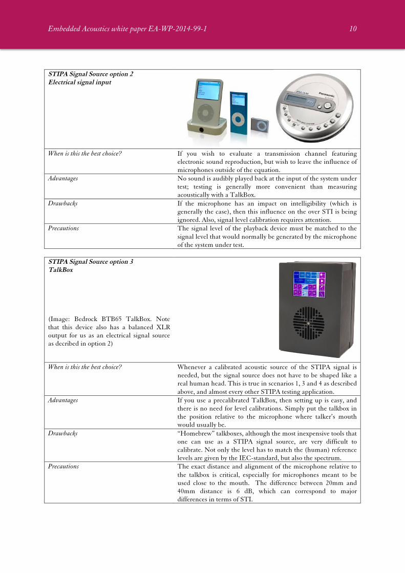
STIPA Signal Source option 2 Electrical signal input
When is this the best choice? If you wish to evaluate a transmission channel featuring
electronic sound reproduction, but wish to leave the influence of microphones outside of the equation.
Advantages No sound is audibly played back at the input of the system under test; testing is generally more convenient than measuring acoustically with a TalkBox.
Drawbacks If the microphone has an impact on intelligibility (which is generally the case), then this influence on the over STI is being ignored. Also, signal level calibration requires attention.
Precautions The signal level of the playback device must be matched to the signal level that would normally be generated by the microphone of the system under test.
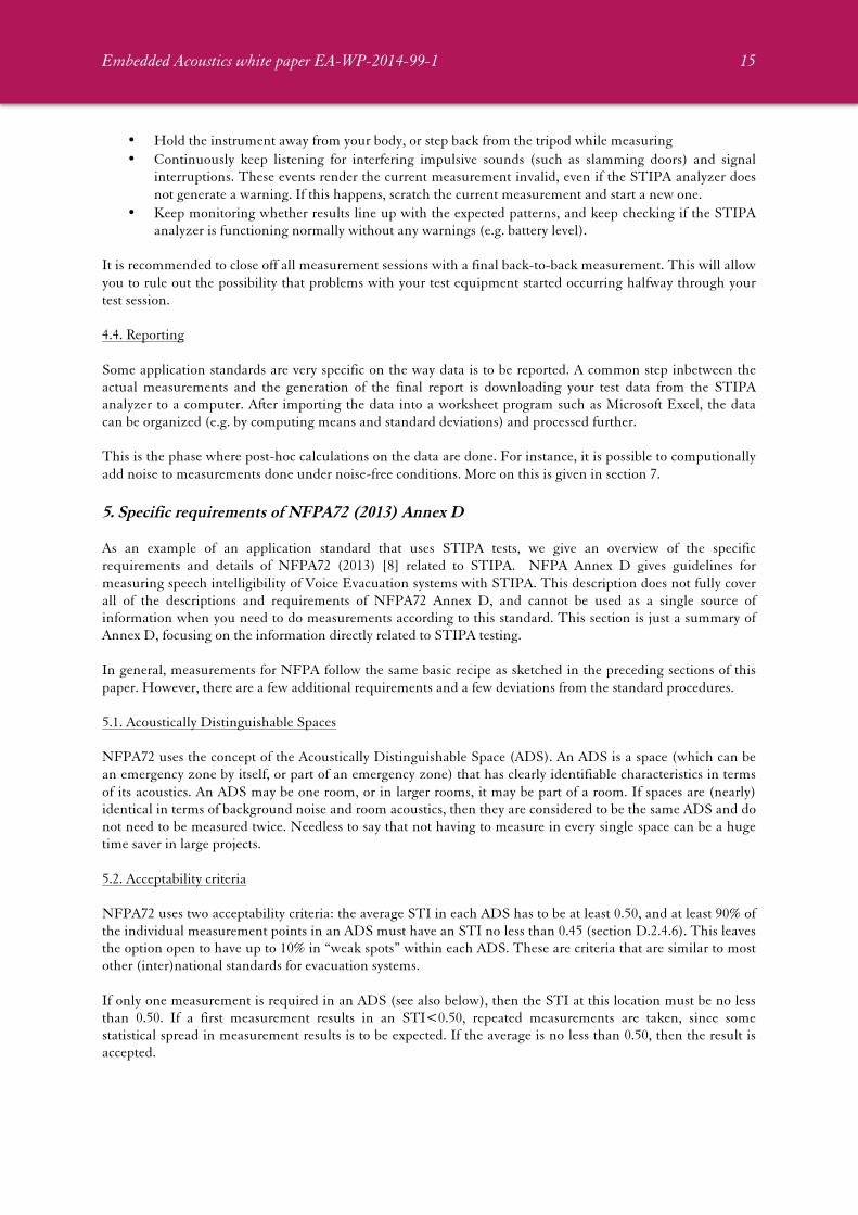
STIPA Signal Source option 3 TalkBox (Image: Bedrock BTB65 TalkBox. Note that this device also has a balanced XLR output for us as an electrical signal source as decribed in option 2)
When is this the best choice? Whenever a calibrated acoustic source of the STIPA signal is
needed, but the signal source does not have to be shaped like a real human head. This is true in scenarios 1, 3 and 4 as described above, and almost every other STIPA testing application.
Advantages If you use a precalibrated TalkBox, then setting up is easy, and there is no need for level calibrations. Simply put the talkbox in the position relative to the microphone where talker’s mouth would usually be.
Drawbacks “Homebrew” talkboxes, although the most inexpensive tools that one can use as a STIPA signal source, are very difficult to calibrate. Not only the level has to match the (human) reference levels are given by the IEC-standard, but also the spectrum.
Precautions The exact distance and alignment of the microphone relative to the talkbox is critical, especially for microphones meant to be used close to the mouth. The difference between 20mm and 40mm distance is 6 dB, which can correspond to major differences in terms of STI.

Embedded Acoustics white paper EA-WP-2014-99-1
11
STIPA Signal Source option 4 Head and Torso Simulator (HATS) (Image: Embedded Acoustics STIPAhats, a specialty tool for measuring the STI with SCBA face masks)
When is this the best choice? Whenever the shape of the human head has an impact on the
outcome of the STIPA tests. This is the case when testing face masks and certain types of headsets.
Advantages The closest match to a real human talker technically achievable. Drawbacks Moderately to very expensive, heavy, difficult to calibrate. Precautions Make sure that a HATS is truly what your application requires.
If so, precisely follow the procedures for using the HATS (usually explained in detail in an application standard).
The words “level calibration” came up for signal sources 1 and 2. Whereas talkboxes and HATS’s generally make sure that the STIPA signal level corresponds to “normal” levels of human speech, this is not the case when using electronic playback devices and signal files. If you use a STIPA signal file or sound player, then it is your responsibility to match the signal level to the level of speech normally played back. Th procedure to match the STIPA level to the level of the speech messages is (in general) as follows:
• Measure the A-weighted equivalent continuous Sound Pressure Level of a representative set of voice messages. This type of measurement, indicated as LAeq and sometimes also called the time-averaged A-weighted level, is measured by every kind STIPA analyzer.
• When selecting voice messages to base the LAeq measurement on, make sure that all natural pauses (between words) are included, but avoid unnaturally long pauses between sentences.
• LAeq is essentially the level of your spoken messages to be matched by the STIPA signal. But there is a catch: the STIPA signal is fully continuous, whereas real speech contains natural pauses, as mentioned before. Simply matching the level of the STIPA signal to the speech level result in a level that is too low – adjustment for the pauses is needed. IEC60268-16 rev.4 (section 5.1) [5] states that a correction factor of 3 dB must be applied. In other words: make sure that the LAeq of the STIPA signal is 3 dB higher than the LAeq you measure for a representative selection of spoken messages.
In cases where the STIPA signal is generated electrically or played back from a file, matching the level of the signal to the expected speech level is absolutely essential. Matching takes place based on the equivalent-continuous (aka time-averaged) A-weighted Sound Pressure Level. The LAeq of the STIPA signal has to be set 3 dB higer than the (average) LAeq of a set of representative spoken messages.
If you use a calibrated talkbox or HATS, these calibrations are generally not necessary. These devices are pre-calibrated to match the source power and directivity of a human speaker. However, it is good practice to always verify that the talkbox does indeed produce the correct level. The level produced by human talkers may vary somewhat; people tend to speak a bit louder during presentations than during relaxed conversations in a quiet environment. The term “vocal effort” is used to indicate the A-weighted sound pressure level at a distance of 1 meter from the mouth. Standardized values for the vocal effort, as used in the STI-standard IEC-60268-16 [5], are defined by ISO-9921 [6]. This standard

Embedded Acoustics white paper EA-WP-2014-99-1
12
defines that “normal” speech corresponds to a vocal effort of 60 dB(A) measured at 1 meter distance. “Relaxed” speech is defined at 54 dB(A), and “raised” as 66 dB(A). A further series of levels is defined in 6 dB steps, up to “maximum shout” at 90 dB(A).
Based on ISO-9921, IEC-60268-16 rev. 4 states that the reference speech level from a talkbox has to be 60 dB(A) at a distance of 1 meter. Always use this value as your baseline level, unless you are dealing with an application standard that explicitly contradicts the STI standard and calls for a different reference level (such as NFPA72). It is common practice to investigate the influence of vocal effort variations by adjusting the level in 6 dB steps, from 54 dB(A) to 72 dB(A). Levels measured at 1 meter distance higher than 72 dB(A), or at most 78 dB(A), are not to be considered realistic in most scenarios.
Note that is usually not practical to verify the talkbox level by literally measuring the level at a distance of 1 meter. At this distance, the acoustics of the room may have a significant disturbing influence on vocal effort measurements. Instead, it is recommended to verify the talkbox level settings a distances of 0.50 and/or 0.25 meter, correcting for the difference in distance.
The reference level of 60 dB(A) at 1 meter distance corresponds to 66 dB(A) measured at 0.50m and 72 dB(A) at 0.25m. The level decreases by 6 dB whenever the distance is doubled.
3.3. STIPA analyzer We have discussed how the STIPA signal source replaces the talker. Similarly, the STIPA analyzer replaces the listener. The difference is that there is usually only one talker, at a fixed position, whereas in most scenarios there are many listeners who have the freedom to move around. This means that many measurements are usually done in a variety of locations, while the operator moves the STIPA analyzer from place to place. Fortunately, these days STIPA analyzers are compact handheld-devices capable of operating on battery power.
Figure 2. The Bedrock SM50 STIPA meter [7]. Whereas this instrument was originally developed as a STIPA meter, and has basic as well as more advanced STIPA features, it also includes other acoustic measurement modules, such as
a real-time spectrum analyzer and a sound pressure level meter. A STIPA analyzer generally consists of the following components:
• A microphone. The STI standards that the microphone has to comply with class 2 / type 2 specifications, or better.
• An internal pre-amplifier for the microphone signal. • A central signal processing unit, that computes the STI from acoustic signals. • A display device • Buttons and/or touch screen to control the device

Embedded Acoustics white paper EA-WP-2014-99-1
13
• Batteries or external power source. • A USB or serial connector to download data to a computer
For general instructions on how to operate the STIPA analyzer, you will need to consult the manual of your device. This differs between device types and manufacturers. The basic principles remain the same across all STIPA measuring instruments. When purchasing a STIPA analyzer, it is essential that the device complies with the latest standard. This is currently IEC-60268-16 rev. 4 (2011). Other important aspects to consider are easy-of-use (some user interfaces are very complex) and advanced processing options (such as computationally adding background noise to STIPA measurements). 4. Generic STIPA test procedures 4.1. Drafting a test plan The first step for any STIPA-based evaluation is to draft a test plan. By drafting a plan ahead of the actual measurements, you make sure that nothing is forgotten once you actually run the tests, and you limit the (usually valuable) time needed at the actual test venue. This also gives you a chance to review the standards that apply to your type of testing in case the transmission channel under test has some unusual characteristics, or if you are dealing with missing our ambiguous specifications. Input for the test plan usually comes from the following sources:
• The schedule of requirements for the speech transmission channel under test: what is the purpose of the channel, and what levels of performance are required?
• The applicable standards, which are usually cited in a schedule of requirements, but may also implicitly be applicable by law. IEC-60268-16 applies to STIPA tests, but this only describes the test methodology itself. Application standards, often set at the national level, further define exactly how and where you need to do STIPA tests. Examples of such application standards are NFPA72 Annex D (USA) and NEN2575 (Netherlands). Description of all application standards is beyond the scope of this paper, since there are many different standards which are also changed quite often.
• Additional (local) regulations. Sadly, it is not uncommon that very specific rules apply at the level of the individual city. The only way to deal with this is to take inventory of regulations on a project-by-project basis.
• Specifications and descriptions of the (electronic) equipment that is part of the tested transmission channel: loudspeaker datasheets, device manuals, etc.
• Information on the test venue: blueprints, data on expected occupancy, expected background noise levels, placement of loudspeakers, etc.
• Interviews with the end customer and/or authority having jurisdiction (in case of systems used for evacuation purposes. Even a short phone call before the test plan is finalized may be enough to avoid unpleasant surprises further down the line, when the written test report is discussed.
• For complex projects, a visit to the test venue may be worth the invested time, just to get an impression of aspects that are not easily gleaned from documents and blueprints.
Information from this variety of sources has to be distilled into a test plan, which often takes the form of an itemized list:
• Which equipment to bring. • Where to set the equipment up, and how to calibrate it. • Which rooms/spaces to measure; how many measuring positions per room, and at which approximate
locations; how many repeated measurements per location. • Which post-processing actions to take. • Other measurements and registrations besides STIPA, such as background noise level measurements.

Embedded Acoustics white paper EA-WP-2014-99-1
14
Many standards require that all primary registrations of the measurements are logged. Sometimes test plans are written in a tabular format, that allows registration of measurement data right into the test plan document (which then also serves as a measurement log). While the importance of having a solid test plan cannot be emphasized enough, it should also be noted that even the best plan usually has to be changed the very minute you enter the test venue. Even then, having a carefully considered and documented test plan helps; it will keep you on track while you try to be as flexible as possible in dealing with the unexpected. 4.2. Setting up equipment and calibrating Before the actual start of measurements, all equipment has to be checked, charged, and calibrated. Next, the equipment has to be set up and prepared for the measurements.
• The talkbox has to be set up in front of the microphone, at the correct distance and properly aligned. The sound level of the talkbox has to be verified against the reference speech level (usually 60 dB(A)).
• In scenarios where an electronic or file-based STIPA signal input is used, the STIPA signal level has to be matched to the level of spoken messages. This requires LAeq measurements of speech at a representative test location, followed by LAeq measurements for the STIPA signal. The STIPA signal is then adjusted to be 3 dB higher than the measured speech levels.
• Level calibration of the STIPA analyzer is checked by means of a level calibrator (if available) and adjusted if necessary.
• The STIPA analyzer is prepared for the measurements (e.g. mounted on a tripod adjusted to the correct measuring height).
• A so-called back-to-back measurement of the measuring system should always be done at the beginning of each test session. This takes just a few minutes, and will reveal any problems with your test equipment.
A back-to-back measurement is done by placing the STIPA analyzer close to the talkbox and performing STIPA and level measurements. Make sure that the talkbox and STIPA analyzer are positioned at least 1 meter away from reflecting surfaces, and place the tip of the microphone in front of the loudspeaker, at a distance of 0.25m. Now adjust the talkbox to 60 dB(A) at 1 meter, and carry out a STIPA measurement. Verify that the level is 72 dB(A) (+ 1 dB), and that the STI>0.96.
If the level or STI do not reach the target values, check for problems with your setup and make adjustments where needed. Clearly mark the back-to-back measurement in your log and save the measurement data on your STIPA analyzer. 4.3. Walking measuring grids and collecting data Especially at large venues, the number of individual STIPA measurements may be quite high, depening on the application standard that you are following. In larger spaces, it helps to mark all measuring points on a map, or even physically by means of markers on the ground. It is recommended to mount the STIPA analyzer on a tripod, for two reasons: it helps you to maintain the prescribed height (often 1.50m), and it allows for more stable measurements. It is good practice to take a step back from the device after starting the measurement, to minimize interference with the measurement. While this phase comprises the bulk of the work to be done for any evaluation, the routine is usually quite easy. Problems with the transmission channel and test equipment have usually been caught in an earlier phase. Still, attention is needed to perform the measures correctly and stay alert for potential measurement issues:
• Stay clear from all reflective surfaces by at least 1 meter
Embedded Acoustics white paper EA-WP-2014-99-1
15
• Hold the instrument away from your body, or step back from the tripod while measuring • Continuously keep listening for interfering impulsive sounds (such as slamming doors) and signal
interruptions. These events render the current measurement invalid, even if the STIPA analyzer does not generate a warning. If this happens, scratch the current measurement and start a new one.
• Keep monitoring whether results line up with the expected patterns, and keep checking if the STIPA analyzer is functioning normally without any warnings (e.g. battery level).
It is recommended to close off all measurement sessions with a final back-to-back measurement. This will allow you to rule out the possibility that problems with your test equipment started occurring halfway through your test session. 4.4. Reporting Some application standards are very specific on the way data is to be reported. A common step inbetween the actual measurements and the generation of the final report is downloading your test data from the STIPA analyzer to a computer. After importing the data into a worksheet program such as Microsoft Excel, the data can be organized (e.g. by computing means and standard deviations) and processed further. This is the phase where post-hoc calculations on the data are done. For instance, it is possible to computionally add noise to measurements done under noise-free conditions. More on this is given in section 7. 5. Specific requirements of NFPA72 (2013) Annex D As an example of an application standard that uses STIPA tests, we give an overview of the specific requirements and details of NFPA72 (2013) [8] related to STIPA. NFPA Annex D gives guidelines for measuring speech intelligibility of Voice Evacuation systems with STIPA. This description does not fully cover all of the descriptions and requirements of NFPA72 Annex D, and cannot be used as a single source of information when you need to do measurements according to this standard. This section is just a summary of Annex D, focusing on the information directly related to STIPA testing. In general, measurements for NFPA follow the same basic recipe as sketched in the preceding sections of this paper. However, there are a few additional requirements and a few deviations from the standard procedures. 5.1. Acoustically Distinguishable Spaces NFPA72 uses the concept of the Acoustically Distinguishable Space (ADS). An ADS is a space (which can be an emergency zone by itself, or part of an emergency zone) that has clearly identifiable characteristics in terms of its acoustics. An ADS may be one room, or in larger rooms, it may be part of a room. If spaces are (nearly) identical in terms of background noise and room acoustics, then they are considered to be the same ADS and do not need to be measured twice. Needless to say that not having to measure in every single space can be a huge time saver in large projects. 5.2. Acceptability criteria NFPA72 uses two acceptability criteria: the average STI in each ADS has to be at least 0.50, and at least 90% of the individual measurement points in an ADS must have an STI no less than 0.45 (section D.2.4.6). This leaves the option open to have up to 10% in “weak spots” within each ADS. These are criteria that are similar to most other (inter)national standards for evacuation systems. If only one measurement is required in an ADS (see also below), then the STI at this location must be no less than 0.50. If a first measurement results in an STI<0.50, repeated measurements are taken, since some statistical spread in measurement results is to be expected. If the average is no less than 0.50, then the result is accepted.

Embedded Acoustics white paper EA-WP-2014-99-1
16
5.3. Selection of measurement locations and test conditions NFPA72 Annex D recognizes that intelligibility testing might not be necessary in every space. Reasons mentioned not to include a space for STIPA testing are the fact that a room is small (<30x30ft), the distance to speakers is small (<30ft), ceilings are low, and there are no hard surfaces such as marble or tile. Even in more challenging environments, NFPA72 allows for STIPA testing to be omitted, if the voice evac system is known to be designed by an experienced and skilled designer, making use of acoustic modeling software. In all other cases (larger rooms, hard surfaces, high ceilings), speech intelligibility testing is required. For every ADS that requires intelligibility testing, measurement locations need to be selected. The basic rules are as follows:
• Measurement locations are separated by approx. 40ft. So in smaller rooms, there will be only one measurement point
• No more than 1/3 of the measurement points is allowed to be on the axis of a loudspeaker • Points of particular interest should be included. Special attention goes to suspected worst-case
locations (near noise sources) and egress paths. • Three measurements are done at each location.
The measuring height is always 5ft (1.5 m). Measurement locations need to be mark on a plan (included as part of the test plan) for future reference. To take the influence of background noise into account, NFPA72 allows occupied testing (when the background noise is representative), or unoccupied testing, in which case the occupied ambient noise is measured separately and included in results through post-hoc calculations. The latter option is less disruptive and therefore usually preferred; see section 7 of this section for a description of the procedures. 5.4. Setting up and calibrating NFPA72 gives two options for calibrating the talkbox: a relatively complex procedure described in section D4 of the standard, or “according to the manufacturers instructions.” We recommend the latter. For the Bedrock BTB65 TalkBox, this procedure is described in section 4.2 of this paper. Simply verify that the level at 0.25m distance is 12 dB higher than your reference speech level, and carry out a back-to-back STI measurement to confirm that the STI>0.96. The procedure for matching the STIPA signal level to the level of speech (for electric signal input of file-based scenarios), the procedure is the same as the general procedure described in this paper. A wide tolerance margin is allowed; the levels of speech and STIPA signal are allowed to deviate up to + 3 dB. NFPA72 uses 65 dB(A) as a reference speech level instead of 60 dB(A). This is a remarkable and unorthodox choice. The rationale for using a higher vocal effort is absolutely valid: people usually have a tendency to speak louder when making voice announcements, in particular in an evacuation scenario. However, in the context of other standards, one might have expected 66 dB(A), as vocal effort is usually specified on a scale with 6 dB steps. This may be inconvenient with some talkboxes and signal generators, since default settings are usually based on these 6 dB steps.
For NFPA72, talkboxes need to be adjusted to different values than the normal reference value. The reference value according to NFPA72 is 65 dB(A). To investigate the influence of differences in vocal effort, the standard recommends doing measurements at 60 dB(A) and 70 dB(A) for at least one measurement location.

Embedded Acoustics white paper EA-WP-2014-99-1
17
5.5. Post-processing and reporting All of the usual information is to be included in the test report; the standard gives an explicit itemized list:
• Building location and related descriptive facility information • Names, titles, and contact information for individuals involved in test • Dates and times of tests • A list of testing instruments, including manufacturer’s name, model, serial number, and date of most
recent calibration • Technical description of emergency communications system Identification of ADSs • Locations of specific measurement points (in a list or on a set of drawings) • Site definition of ambient sound pressure levels • STI/STIPA measurements at each measurement point • Final corrected STI/STIPA values where the post- processing procedure is used • Indication of whether or not the test met the pass/fail criteria • Record of system restoration (proving that the system is restored to its original state after the test) • Any additional information to assist with future evaluation of system performance
The final result for each measurement point is calculated as the average of the three individual measurements at each point, corrected for ambient background noise (if applicable). For each ADS, the data from all measurement points combined results in a pass/fail conclusion. 6. Limitations of STIPA The Speech Transmission Index model, by its nature and design, has some limitations that render it less accurate (or even virtually useless) is specific situations. Whereas these situations may be rare in practice, it is always good to be aware of these limitations:
• Advanced digital low-bitrate voice coding systems do not accurately reproduce STI signals. STI signals are no real speech, but modulated noise; low-bitrate voice coders (such as systems used for military communications) actually suppress the STI signals instead of transmitting these. Cell phones can usually be tested, but not always – test results should be carefully scrutinized for inconsistency.
• Aggressive noise reduction algorithms also do not permit the use of noise-based test signals • The STI is inaccurate for systems that feature center clipping. This was a common type of distortion in
the days of carbon microphones, but it is very rare these days. STIPA is an implementation of the STI that uses fewer modulation frequencies per octave band than the original “full STI”. Due to a clever scheme that alternates modulation frequencies across octave bands, the entire modulation spectrum is still taken into account, but not for each octave band. This has been rigorously validated [] and proven to be accurate in almost every PA-related application (and virtually every other application as well). The only exception is when strong discrete echoes are observed, such as in some cathedrals and other very large venues.
The one limitation of STIPA (and the Speech Transmission Index in general) that requires constant attention is that the STI does not deal well with impulsive noises and signal interruptions.
In case of impulsive noises occurring during a STIPA measurement, such as door slams and accidental taps on the microphone, the STI measurement is rendered highly inaccurate. The same is true if the test signal has been interrupted during a measurement, however briefly. Some STIPA instruments (such as the Bedrock SM50) are capable of automatically detecting many, but not all, cases when measurements are invalidated. Even if the instrument does not generate a warning, discard a measurement whenever you observe impulse noises or signal interruptions.
Embedded Acoustics white paper EA-WP-2014-99-1
18
7. More advanced aspects of STIPA testing 7.1. Adding ambient noise through post-hoc calculations The possibility to add in ambient noise through post-hoc calculations was mentioned several times before. This is one of many advanced post-processing options offered by the STI model. Most of these options are beyond the scope of this paper, but adding noise computationally is so common (and useful) that the procedure is described here. If ambient noise is present during a STIPA measurement, its effect on intelligibility is taken into account automatically. Noise reduces the modulation depth of the STIPA signal, which is detected by the analyzer. But even if the noise is not physically present during the STIPA measurement, it can be included in the STI results, as long as the octave band spectrum is known. From the octave band spectrum, in combination with a “noise-free” STIPA measurement, the influence of the noise on the STI can be calculated after the fact. If the octave band noise spectrum has been measured accurately, this is just as reliable (and computationally equivalent) to measuring the STI directly in the presence of the ambient noise. The mathematics for this operation follow directly from the STI standard [5]. In practice, there are two alternative procedures to add ambient noise: Procedure 1. On the STIPA analyzer
• Measure the octave band spectrum of the ambient noise under representative conditions. Do NOT play the STIPA signal during this measurement.
• Some STIPA analyzers (such at the Bedrock SM50) allow you to enter the octave band noise spectrum directly into the STIPA analyzer.
• Now measure the STI under noise-free conditions. The STIPA analyzer provides two different STI numbers for each measurement: with and without (computationally added) noise.
Procedure 2. Afterwards in MS Excel
• Measure the STI under noise-free conditions, covering all the data points of interest. Store the data.
• Before or after the STI measurements, measure the octave band spectrum of the ambient noise under representative conditions. Do NOT play the STIPA signal during this measurement.
• After completion of all STI measurements, MS Excel tools (usually provided by the manufacturer of the STIPA analyzer) are used to add the noise to each STI measurement.
Which method is preferred depends on the situation. Procedure 1 is usually much more convenient, and allows you to evaluate the effect of the noise as you carry out your measurements. You will be able to adjust you test plan on the fly to address the impact of the ambient noise, if the need arises. However, not all STIPA analyzers give this option. Also, in same cases the ambient noise spectrum may not be known at the time the STIPA measurements take place. For instance, you may only have access to do elaborate STIPA tests before a venue is opened to the public, whereas you can only measure the ambient noise in the occupied state, after the venue has been opened to the public. 7.2. Level-dependent masking Speech intelligibility partly depends on the absolute level of the speech. At very low speech levels as well as at high speech levels intelligibility decreases. This is due to imperfections of the human hearing organ, which suffers from a greater level of (internal) auditory masking at higher sound levels. This effect, known as level-dependent masking, is taken into account by the STI model. However, in some cases, the actual level of the sound may not be known beforehand. For instance, evaluation of the performance of the combined electronics of a PA system is a task for which the STI is particularly suited. But these electronics may be used at a range of sound levels, from very high to very low. Incorporating the effect of level dependency does not make sense. For this reason, STIPA analyzers often give the option to disable level

Embedded Acoustics white paper EA-WP-2014-99-1
19
dependent masking. This option is sometimes also useful during back-to-back measurements: even if there is no signal distortion at all, at high sound levels (>75 dB(A)) the STI will never approach the theoretical maximum of 1.00. With level dependent masking disabled, STI-values >0.97 can be measured at any sound pressure level, as long as the transmission channel is completely free from interfering influences.
Disabling “level dependent masking” will lead to higher STI values at very low sound levels and at higher sound levels. Disabling level dependent masking is ONLY a valid choice when there is no acoustic reference, or when testing the measuring setup itself. Having level dependent masking disabled during any other kind of measurement leads to results that are too optimistic, and basically comes down to cheating.
8. Conclusions and discussion STIPA offers a convenient, relatively easy to use and reliable way to obtain objective data on speech intelligibility. This paper is an attempt to give an introductory overview of the procedures involved in STIPA testing. The Speech Transmission Index model opens up a wide spectrum of possibilities in terms of diagnostic analysis of speech transmission channels. This paper barely scratches the surface in that respect. Other resources are available that demonstrate how the STI helps troubleshoot systems, pinpointing root causes for intelligibility problems. Also, post-hoc calculations can be performed for much wider purposes that just adding background noise. References [1] Sander J. van Wijngaarden, Ed.(2002) “Past Present and Future of the Speech Transmission Index,”
TNO Human Factors, Soesterberg. Downloadable from www.embeddedacoustics.com
[2] Various documents available for download from www.embeddedacoustics.com
[3] Steeneken, H.J.M. and Houtgast, T. (1980), “A physical method for measuring speech transmission quality”, J. Acoust. Soc. Amer. 67, 31, p.318-326
[4] Steeneken, H.J.M., Verhave, J.A., McManus, S., and Jacob, K.D., (2001) “Development of an Accurate, Handheld, Simple-to-use Meter for the Prediction of Speech Intelligibility”, Proceedings IoA 2001, Reproduced sound (17). Stratford-upon-Avon, UK.
[5] IEC 60268-16 (2011) rev. 4. “Sound system equipment — Part 16: Objective rating of speech intelligibility by speech transmission index,” International Electrotechnical Commission, Geneva, Switzerland.
[6] ISO 9921 (2003) “Ergonomics – Assessment of speech communication.” International Standards Organisation, Geneva, Switzerland
[7] Details on the Bedrock SM50 and BTB65 Talkbox are found at www.bedrock-audio.com
[8] NFPA72 (2013) “National Fire Alarm and Signaling Code,” National Fire Protection Association, Quincy, Massachusetts, USA.