spill prevention control and countermeasure plan · pdf fileuniversity of nevada, las vegas...
TRANSCRIPT
SPILL PREVENTION, CONTROL, AND COUNTERMEASURE PLAN
University of Nevada, Las Vegas
4505 South Maryland Parkway Las Vegas, Nevada 89154
June 22, 2008 Revised August 22, 2008
Prepared by Southwest Hydrology & Hydraulics, LLC
Boulder City, Nevada, 89005
Version 1.0, 6/22/2008
University of Nevada, Las Vegas Spill Prevention, Control, and Countermeasure (SPCC) Plan
Version 1.0, 6/22/08 -ii-
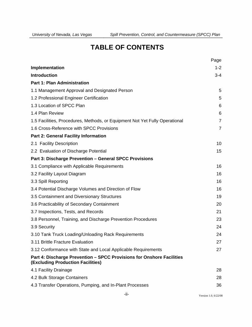
TABLE OF CONTENTS
Page
Implementation 1-2
Introduction 3-4
Part 1: Plan Administration
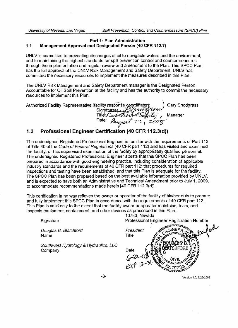
1.1 Management Approval and Designated Person 5
1.2 Professional Engineer Certification 5
1.3 Location of SPCC Plan 6
1.4 Plan Review 6
1.5 Facilities, Procedures, Methods, or Equipment Not Yet Fully Operational 7
1.6 Cross-Reference with SPCC Provisions 7
Part 2: General Facility Information
2.1 Facility Description 10
2.2 Evaluation of Discharge Potential 15
Part 3: Discharge Prevention – General SPCC Provisions
3.1 Compliance with Applicable Requirements 16
3.2 Facility Layout Diagram 16
3.3 Spill Reporting 16
3.4 Potential Discharge Volumes and Direction of Flow 16
3.5 Containment and Diversionary Structures 19
3.6 Practicability of Secondary Containment 20
3.7 Inspections, Tests, and Records 21
3.8 Personnel, Training, and Discharge Prevention Procedures 23
3.9 Security 24
3.10 Tank Truck Loading/Unloading Rack Requirements 24
3.11 Brittle Fracture Evaluation 27
3.12 Conformance with State and Local Applicable Requirements 27
Part 4: Discharge Prevention – SPCC Provisions for Onshore Facilities (Excluding Production Facilities) 4.1 Facility Drainage 28
4.2 Bulk Storage Containers 28
4.3 Transfer Operations, Pumping, and In-Plant Processes 36
University of Nevada, Las Vegas Spill Prevention, Control, and Countermeasure (SPCC) Plan
Version 1.0, 6/22/08 -iii-
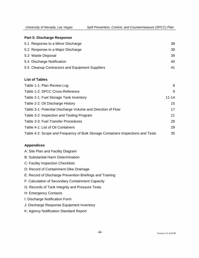
Part 5: Discharge Response
5.1 Response to a Minor Discharge 38
5.2 Response to a Major Discharge 39
5.3 Waste Disposal 39
5.4 Discharge Notification 40
5.5 Cleanup Contractors and Equipment Suppliers 41
List of Tables
Table 1-1: Plan Review Log 8
Table 1-2: SPCC Cross-Reference 9
Table 2-1: Fuel Storage Tank Inventory 11-14
Table 2-2: Oil Discharge History 15
Table 3-1: Potential Discharge Volume and Direction of Flow 17
Table 3-2: Inspection and Testing Program 21
Table 3-3: Fuel Transfer Procedures 26
Table 4-1: List of Oil Containers 29
Table 4-2: Scope and Frequency of Bulk Storage Containers Inspections and Tests 35
Appendices
A: Site Plan and Facility Diagram
B: Substantial Harm Determination
C: Facility Inspection Checklists
D: Record of Containment Dike Drainage
E: Record of Discharge Prevention Briefings and Training
F: Calculation of Secondary Containment Capacity
G: Records of Tank Integrity and Pressure Tests
H: Emergency Contacts
I: Discharge Notification Form
J: Discharge Response Equipment Inventory
K: Agency Notification Standard Report
University of Nevada, Las Vegas Spill Prevention, Control, and Countermeasure (SPCC) Plan
Version 1.0, 6/22/08 -iv-
LIST OF ACRONYMS AND ABBREVIATIONS AST Aboveground Storage Tank EPA U.S. Environmental Protection Agency NDEP Nevada Division of Environmental Protection NPDES National Pollutant Discharge Elimination System PE Professional Engineer POTW Publicly Owned Treatment Works SPCC Spill Prevention, Control, and Countermeasure STI Steel Tank Institute
UST Underground Storage Tank
University of Nevada, Las Vegas Spill Prevention, Control, and Countermeasure (SPCC) Plan
Version 1.0, 6/22/2008 -1-
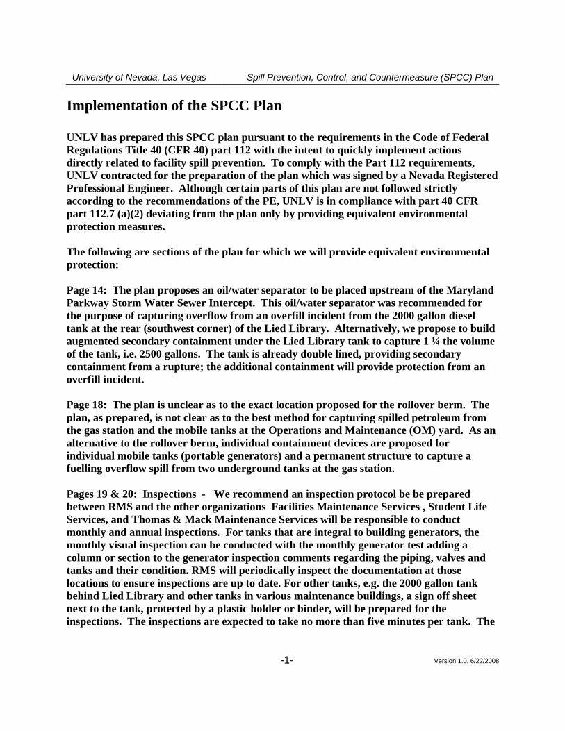
Implementation of the SPCC Plan UNLV has prepared this SPCC plan pursuant to the requirements in the Code of Federal Regulations Title 40 (CFR 40) part 112 with the intent to quickly implement actions directly related to facility spill prevention. To comply with the Part 112 requirements, UNLV contracted for the preparation of the plan which was signed by a Nevada Registered Professional Engineer. Although certain parts of this plan are not followed strictly according to the recommendations of the PE, UNLV is in compliance with part 40 CFR part 112.7 (a)(2) deviating from the plan only by providing equivalent environmental protection measures. The following are sections of the plan for which we will provide equivalent environmental protection: Page 14: The plan proposes an oil/water separator to be placed upstream of the Maryland Parkway Storm Water Sewer Intercept. This oil/water separator was recommended for the purpose of capturing overflow from an overfill incident from the 2000 gallon diesel tank at the rear (southwest corner) of the Lied Library. Alternatively, we propose to build augmented secondary containment under the Lied Library tank to capture 1 ¼ the volume of the tank, i.e. 2500 gallons. The tank is already double lined, providing secondary containment from a rupture; the additional containment will provide protection from an overfill incident. Page 18: The plan is unclear as to the exact location proposed for the rollover berm. The plan, as prepared, is not clear as to the best method for capturing spilled petroleum from the gas station and the mobile tanks at the Operations and Maintenance (OM) yard. As an alternative to the rollover berm, individual containment devices are proposed for individual mobile tanks (portable generators) and a permanent structure to capture a fuelling overflow spill from two underground tanks at the gas station. Pages 19 & 20: Inspections - We recommend an inspection protocol be be prepared between RMS and the other organizations Facilities Maintenance Services , Student Life Services, and Thomas & Mack Maintenance Services will be responsible to conduct monthly and annual inspections. For tanks that are integral to building generators, the monthly visual inspection can be conducted with the monthly generator test adding a column or section to the generator inspection comments regarding the piping, valves and tanks and their condition. RMS will periodically inspect the documentation at those locations to ensure inspections are up to date. For other tanks, e.g. the 2000 gallon tank behind Lied Library and other tanks in various maintenance buildings, a sign off sheet next to the tank, protected by a plastic holder or binder, will be prepared for the inspections. The inspections are expected to take no more than five minutes per tank. The
University of Nevada, Las Vegas Spill Prevention, Control, and Countermeasure (SPCC) Plan
Version 1.0, 6/22/2008 -2-
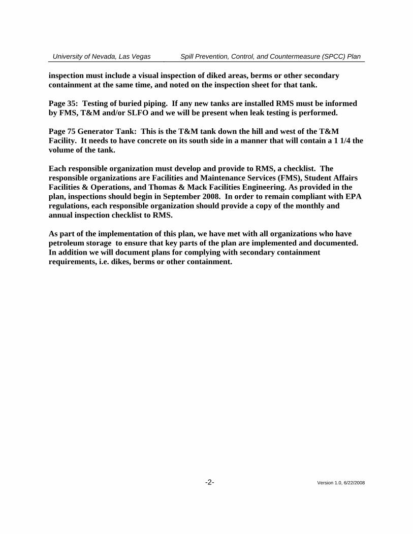
inspection must include a visual inspection of diked areas, berms or other secondary containment at the same time, and noted on the inspection sheet for that tank. Page 35: Testing of buried piping. If any new tanks are installed RMS must be informed by FMS, T&M and/or SLFO and we will be present when leak testing is performed. Page 75 Generator Tank: This is the T&M tank down the hill and west of the T&M Facility. It needs to have concrete on its south side in a manner that will contain a 1 1/4 the volume of the tank. Each responsible organization must develop and provide to RMS, a checklist. The responsible organizations are Facilities and Maintenance Services (FMS), Student Affairs Facilities & Operations, and Thomas & Mack Facilities Engineering. As provided in the plan, inspections should begin in September 2008. In order to remain compliant with EPA regulations, each responsible organization should provide a copy of the monthly and annual inspection checklist to RMS. As part of the implementation of this plan, we have met with all organizations who have petroleum storage to ensure that key parts of the plan are implemented and documented. In addition we will document plans for complying with secondary containment requirements, i.e. dikes, berms or other containment.
University of Nevada, Las Vegas Spill Prevention, Control, and Countermeasure (SPCC) Plan
Version 1.0, 6/22/2008 -3-
INTRODUCTION
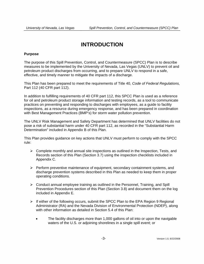
Purpose The purpose of this Spill Prevention, Control, and Countermeasure (SPCC) Plan is to describe measures to be implemented by the University of Nevada, Las Vegas (UNLV) to prevent oil and petroleum product discharges from occurring, and to prepare UNLV to respond in a safe, effective, and timely manner to mitigate the impacts of a discharge. This Plan has been prepared to meet the requirements of Title 40, Code of Federal Regulations, Part 112 (40 CFR part 112). In addition to fulfilling requirements of 40 CFR part 112, this SPCC Plan is used as a reference for oil and petroleum product storage information and testing records, as a tool to communicate practices on preventing and responding to discharges with employees, as a guide to facility inspections, as a resource during emergency response, and has been prepared in coordination with Best Management Practices (BMP’s) for storm water pollution prevention. The UNLV Risk Management and Safety Department has determined that UNLV facilities do not pose a risk of substantial harm under 40 CFR part 112, as recorded in the “Substantial Harm Determination” included in Appendix B of this Plan. This Plan provides guidance on key actions that UNLV must perform to comply with the SPCC rule:
Complete monthly and annual site inspections as outlined in the Inspection, Tests, and Records section of this Plan (Section 3.7) using the inspection checklists included in Appendix C.
Perform preventive maintenance of equipment, secondary containment systems, and
discharge prevention systems described in this Plan as needed to keep them in proper operating conditions.
Conduct annual employee training as outlined in the Personnel, Training, and Spill
Prevention Procedures section of this Plan (Section 3.8) and document them on the log included in Appendix E.
If either of the following occurs, submit the SPCC Plan to the EPA Region 9 Regional
Administrator (RA) and the Nevada Division of Environmental Protection (NDEP), along with other information as detailed in Section 5.4 of this Plan:
• The facility discharges more than 1,000 gallons of oil into or upon the navigable
waters of the U.S. or adjoining shorelines in a single spill event; or
University of Nevada, Las Vegas Spill Prevention, Control, and Countermeasure (SPCC) Plan
Version 1.0, 6/22/2008 -4-
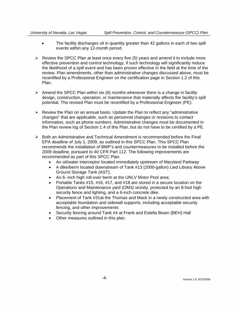
• The facility discharges oil in quantity greater than 42 gallons in each of two spill events within any 12-month period.
Review the SPCC Plan at least once every five (5) years and amend it to include more
effective prevention and control technology, if such technology will significantly reduce the likelihood of a spill event and has been proven effective in the field at the time of the review. Plan amendments, other than administrative changes discussed above, must be recertified by a Professional Engineer on the certification page in Section 1.2 of this Plan.
Amend the SPCC Plan within six (6) months whenever there is a change in facility
design, construction, operation, or maintenance that materially affects the facility’s spill potential. The revised Plan must be recertified by a Professional Engineer (PE).
Review the Plan on an annual basis. Update the Plan to reflect any “administrative
changes” that are applicable, such as personnel changes or revisions to contact information, such as phone numbers. Administrative changes must be documented in the Plan review log of Section 1.4 of this Plan, but do not have to be certified by a PE.
Both an Administrative and Technical Amendment is recommended before the Final EPA deadline of July 1, 2009, as outlined in this SPCC Plan. This SPCC Plan recommends the installation of BMP’s and countermeasures to be installed before the 2009 deadline, pursuant to 40 CFR Part 112. The following improvements are recommended as part of this SPCC Plan.
• An oil/water interceptor located immediately upstream of Maryland Parkway • A dike/berm located downstream of Tank #13 (2000-gallon) Lied Library Above
Ground Storage Tank (AST); • An 6- inch high roll-over berm at the UNLV Motor Pool area; • Portable Tanks #15, #16, #17, and #18 are stored in a secure location on the
Operations and Maintenance yard (OM3) vicinity, protected by an 8-foot high security fence and lighting, and a 6-inch concrete dike.
• Placement of Tank #31at the Thomas and Mack in a newly constructed area with acceptable foundation and sidewall supports, including acceptable security fencing, and other improvements
• Security fencing around Tank #4 at Frank and Estella Beam (BEH) Hall • Other measures outlined in this plan.
University of Nevada, Las Vegas Spill Prevention, Control, and Countermeasure (SPCC) Plan
Version 1.0, 6/22/2008 -6-
1.3 Location of SPCC Plan (40 CFR 112.3(e)) In accordance with 40 CFR 112.3(e), a complete copy of this SPCC Plan is maintained at the UNLV Risk Management and Safety Department. The department is attended from 8:00 AM to 5:00 PM, 5 days per week (closed on Saturdays and Sundays). 1.4 Plan Review (40 CFR 112.3 and 112.5) 1.4.1 Changes in Facility Configuration In accordance with 40 CFR 112.5(a), the UNLV Risk Management and Safety Department periodically reviews and evaluates this SPCC Plan for any change in the facility design, construction, operation, or maintenance that materially affects the facility’s potential for an oil discharge, including, but not limited to:
• commissioning of containers; • reconstruction, replacement, or installation of piping systems; • construction or demolition that might alter secondary containment structures; or • changes of product or service, revisions to standard operation, modification of
testing/inspection procedures, and use of new or modified industry standards or maintenance procedures.
Amendments to the Plan made to address changes of this nature are referred to as technical amendments, and must be certified by a PE. Non-technical amendments can be done (and must be documented in this section) by the facility owner and/or operator. Non-technical amendments include the following:
• change in the name or contact information (i.e., telephone numbers) of individuals responsible for the implementation of this Plan; or
• change in the name or contact information of spill response or cleanup contractors. The UNLV Risk Management and Safety Department should make the needed revisions to the SPCC Plan as soon as possible, but no later than six months after the change occurs. The Plan should be implemented as soon as possible following any technical amendment, but no later than six months from the date of the amendment. The department manager is responsible for initiating and coordinating revisions to the SPCC Plan. 1.4.2 Scheduled Plan Reviews In accordance with 40 CFR 112.5(b), the UNLV Risk Management and Safety Department reviews this SPCC Plan at least once every five years. Revisions to the Plan, if needed, are made within six months of the five-year review. A registered Professional Engineer certifies any technical amendment to the Plan, as described above, in accordance with 40 CFR 112.3(d). This is the first SPCC Plan and no other review has occurred. This Plan is dated June 22, 2008. The next plan review is therefore scheduled to take place on or prior to June 22, 2008.
University of Nevada, Las Vegas Spill Prevention, Control, and Countermeasure (SPCC) Plan
Version 1.0, 6/22/2008 -7-
1.4.3 Record of Plan Reviews Scheduled reviews and Plan amendments are recorded in the Plan Review Log (Table 1-1). This log should be completed even if no amendment is made to the Plan as a result of the review. Unless a technical or administrative change prompts an earlier review of the Plan, the next scheduled review of this Plan must occur before July 1, 2009, to review any Administrative and Technical Amendments. 1.5 Facilities, Procedures, Methods, or Equipment Not Yet Fully
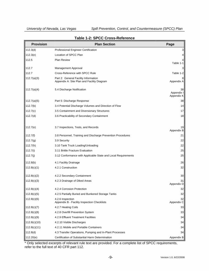
Operational (40 CFR 112.7) Section 4.2.6 of this Plan describes the inspection program to be implemented by the facility following a regular schedule, including the dates by which each of the bulk storage containers must be tested. 1.6 Cross-Reference with SPCC Provisions (40 CFR 112.7) This SPCC Plan does not follow the exact order presented in 40 CFR part 112. Section headings identify, where appropriate, the relevant section(s) of the SPCC rule. Table 1-2 presents a cross-reference of Plan sections relative to applicable parts of 40 CFR part 112.
University of Nevada, Las Vegas Spill Prevention, Control, and Countermeasure (SPCC) Plan
Version 1.0, 6/22/2008 -8-
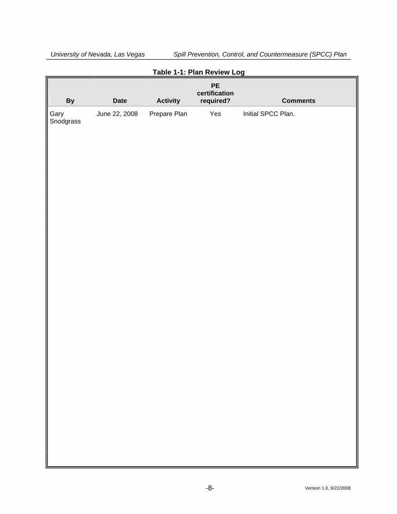
Table 1-1: Plan Review Log
By Date Activity
PE certification required? Comments
Gary Snodgrass
June 22, 2008 Prepare Plan
Yes Initial SPCC Plan.
University of Nevada, Las Vegas Spill Prevention, Control, and Countermeasure (SPCC) Plan
Version 1.0, 6/22/2008 -9-
Table 1-2: SPCC Cross-Reference Provision Plan Section Page
112.3(d) Professional Engineer Certification 3
112.3(e) Location of SPCC Plan 4
112.5 Plan Review 4Table 1-1
112.7 Management Approval 3
112.7 Cross-Reference with SPCC Rule Table 1-2
112.7(a)(3) Part 2: General Facility Information Appendix A: Site Plan and Facility Diagram
8Appendix A
112.7(a)(4) 5.4 Discharge Notification 38Appendix I
Appendix K
112.7(a)(5) Part 5: Discharge Response 38
112.7(b) 3.4 Potential Discharge Volumes and Direction of Flow 14
112.7(c) 3.5 Containment and Diversionary Structures 17
112.7(d) 3.6 Practicability of Secondary Containment
18
112.7(e) 3.7 Inspections, Tests, and Records
19Appendix B
112.7(f) 3.8 Personnel, Training and Discharge Prevention Procedures 21
112.7(g) 3.9 Security 22
112.7(h) 3.10 Tank Truck Loading/Unloading 22
112.7(i) 3.11 Brittle Fracture Evaluation 25
112.7(j) 3.12 Conformance with Applicable State and Local Requirements 25
112.8(b) 4.1 Facility Drainage 26
112.8(c)(1) 4.2.1 Construction
32
112.8(c)(2) 4.2.2 Secondary Containment 30
112.8(c)(3) 4.2.3 Drainage of Diked Areas 31Appendix D
112.8(c)(4) 4.2.4 Corrosion Protection 32
112.8(c)(5) 4.2.5 Partially Buried and Bunkered Storage Tanks 32
112.8(c)(6) 4.2.6 Inspection Appendix B - Facility Inspection Checklists
32Appendix C
112.8(c)(7) 4.2.7 Heating Coils 33
112.8(c)(8) 4.2.8 Overfill Prevention System 33
112.8(c)(9) 4.2.9 Effluent Treatment Facilities 34
112.8(c)(10) 4.2.10 Visible Discharges 34
112.8(c)(11) 4.2.11 Mobile and Portable Containers 34
112.8(d) 4.3 Transfer Operations, Pumping and In-Plant Processes 34
112.20(e) Certification of Substantial Harm Determination Appendix B
* Only selected excerpts of relevant rule text are provided. For a complete list of SPCC requirements, refer to the full text of 40 CFR part 112.
University of Nevada, Las Vegas Spill Prevention, Control, and Countermeasure (SPCC) Plan
Version 1.0, 6/22/2008 -10-
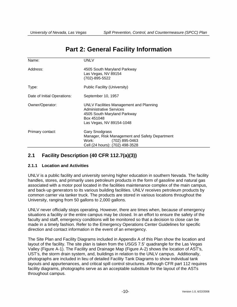
Part 2: General Facility Information
Name: UNLV
Address: 4505 South Maryland Parkway Las Vegas, NV 89154 (702)-895-5522 Type: Public Facility (University) Date of Initial Operations: September 10, 1957
Owner/Operator: UNLV Facilities Management and Planning Administrative Services 4505 South Maryland Parkway Box 451048 Las Vegas, NV 89154-1048 Primary contact: Gary Snodgrass Manager, Risk Management and Safety Department Work: (702) 895-0463 Cell (24 hours): (702) 498-3528
2.1 Facility Description (40 CFR 112.7(a)(3)) 2.1.1 Location and Activities UNLV is a public facility and university serving higher education in southern Nevada. The facility handles, stores, and primarily uses petroleum products in the form of gasoline and natural gas associated with a motor pool located in the facilities maintenance complex of the main campus, and back-up generators to its various building facilities. UNLV receives petroleum products by common carrier via tanker truck. The products are stored in various locations throughout the University, ranging from 50 gallons to 2,000 gallons. UNLV never officially stops operating. However, there are times when, because of emergency situations a facility or the entire campus may be closed. In an effort to ensure the safety of the faculty and staff, emergency conditions will be monitored so that a decision to close can be made in a timely fashion. Refer to the Emergency Operations Center Guidelines for specific direction and contact information in the event of an emergency. The Site Plan and Facility Diagrams included in Appendix A of this Plan show the location and layout of the facility. The site plan is taken from the USGS 7.5’ quadrangle for the Las Vegas Valley (Figure A-1). The Facility and Drainage Map (Figure A-2) shows the location of AST’s, UST’s, the storm drain system, and, buildings in relation to the UNLV campus. Additionally, photographs are included in lieu of detailed Facility Tank Diagrams to show individual tank layouts and appurtenances, and critical spill control structures. Although CFR part 112 requires facility diagrams, photographs serve as an acceptable substitute for the layout of the ASTs throughout campus.
University of Nevada, Las Vegas Spill Prevention, Control, and Countermeasure (SPCC) Plan
Version 1.0, 6/22/2008 -11-
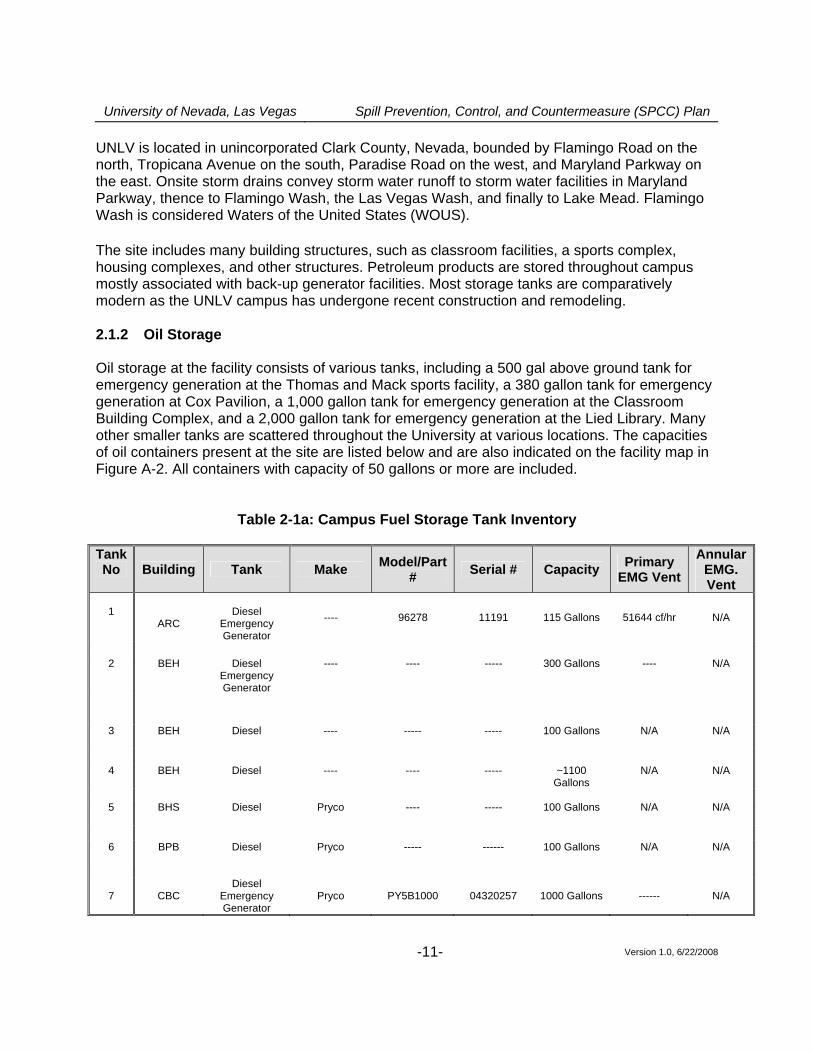
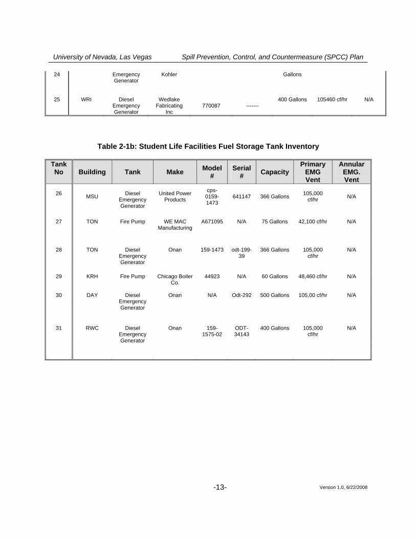
UNLV is located in unincorporated Clark County, Nevada, bounded by Flamingo Road on the north, Tropicana Avenue on the south, Paradise Road on the west, and Maryland Parkway on the east. Onsite storm drains convey storm water runoff to storm water facilities in Maryland Parkway, thence to Flamingo Wash, the Las Vegas Wash, and finally to Lake Mead. Flamingo Wash is considered Waters of the United States (WOUS). The site includes many building structures, such as classroom facilities, a sports complex, housing complexes, and other structures. Petroleum products are stored throughout campus mostly associated with back-up generator facilities. Most storage tanks are comparatively modern as the UNLV campus has undergone recent construction and remodeling. 2.1.2 Oil Storage Oil storage at the facility consists of various tanks, including a 500 gal above ground tank for emergency generation at the Thomas and Mack sports facility, a 380 gallon tank for emergency generation at Cox Pavilion, a 1,000 gallon tank for emergency generation at the Classroom Building Complex, and a 2,000 gallon tank for emergency generation at the Lied Library. Many other smaller tanks are scattered throughout the University at various locations. The capacities of oil containers present at the site are listed below and are also indicated on the facility map in Figure A-2. All containers with capacity of 50 gallons or more are included.
Table 2-1a: Campus Fuel Storage Tank Inventory Tank No Building Tank Make Model/Part
# Serial # Capacity Primary EMG Vent
Annular EMG. Vent
1
ARC
Diesel
Emergency Generator
---- 96278 11191 115 Gallons 51644 cf/hr N/A
2 BEH Diesel
Emergency Generator
---- ---- ----- 300 Gallons ---- N/A
3 BEH
Diesel ---- ----- ----- 100 Gallons N/A N/A
4 BEH Diesel ---- ---- ----- ~1100
Gallons N/A N/A
5 BHS Diesel Pryco ---- ----- 100 Gallons N/A N/A
6 BPB Diesel Pryco ----- ------ 100 Gallons N/A N/A
7 CBC
Diesel Emergency Generator
Pryco PY5B1000 04320257 1000 Gallons ------ N/A
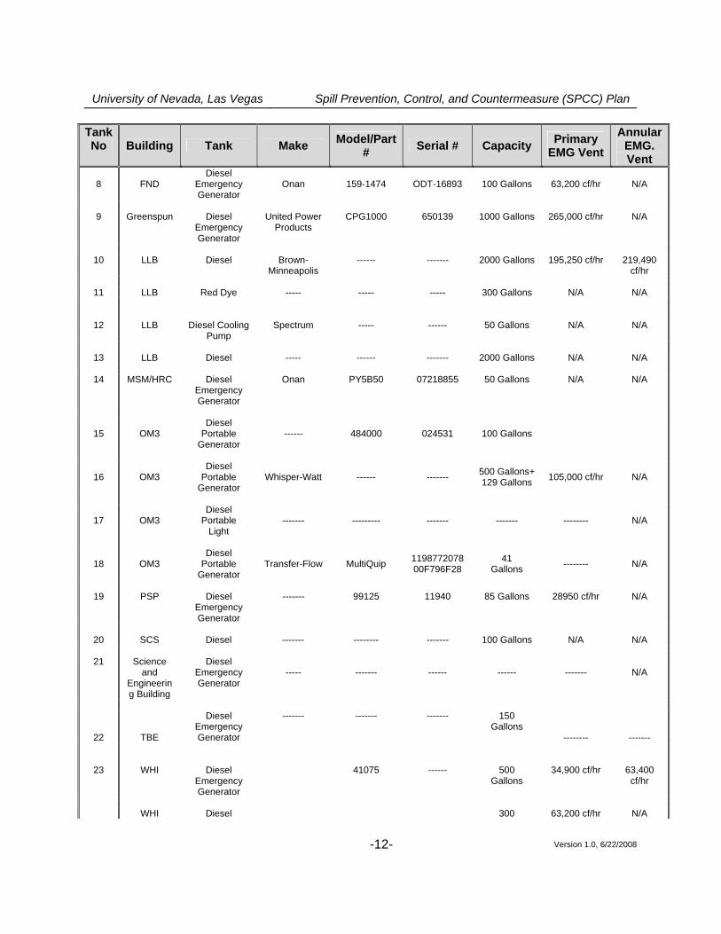
University of Nevada, Las Vegas Spill Prevention, Control, and Countermeasure (SPCC) Plan
Version 1.0, 6/22/2008 -12-
Tank No Building Tank Make Model/Part
# Serial # Capacity Primary EMG Vent
Annular EMG. Vent
8
FND
Diesel Emergency Generator
Onan
159-1474
ODT-16893
100 Gallons
63,200 cf/hr
N/A
9 Greenspun Diesel
Emergency Generator
United Power Products
CPG1000 650139 1000 Gallons 265,000 cf/hr N/A
10 LLB Diesel
Brown-
Minneapolis ------ ------- 2000 Gallons 195,250 cf/hr 219,490
cf/hr
11 LLB Red Dye ----- ----- ----- 300 Gallons N/A N/A
12 LLB Diesel Cooling Pump
Spectrum ----- ------ 50 Gallons N/A N/A
13 LLB Diesel ----- ------ ------- 2000 Gallons N/A N/A
14 MSM/HRC Diesel
Emergency Generator
Onan PY5B50 07218855 50 Gallons N/A N/A
15 OM3 Diesel
Portable Generator
------ 484000 024531 100 Gallons
16 OM3 Diesel
Portable Generator
Whisper-Watt ------ ------- 500 Gallons+ 129 Gallons 105,000 cf/hr N/A
17 OM3 Diesel
Portable Light
------- --------- ------- ------- -------- N/A
18 OM3 Diesel
Portable Generator
Transfer-Flow MultiQuip 119877207800F796F28
41 Gallons -------- N/A
19 PSP
Diesel
Emergency Generator
------- 99125 11940 85 Gallons 28950 cf/hr N/A
20 SCS Diesel ------- -------- ------- 100 Gallons N/A N/A
21 Science
and Engineering Building
Diesel Emergency Generator
-----
-------
------
------
-------
N/A
22
TBE
Diesel Emergency Generator
------- ------- ------- 150 Gallons
-------- -------
23
WHI
Diesel Emergency Generator
41075
------
500 Gallons
34,900 cf/hr
63,400 cf/hr
WHI Diesel 300 63,200 cf/hr N/A
University of Nevada, Las Vegas Spill Prevention, Control, and Countermeasure (SPCC) Plan
Version 1.0, 6/22/2008 -13-
24 Emergency Generator
Kohler
Gallons
25 WRI Diesel
Emergency Generator
Wedlake Fabricating
Inc
770087
-------
400 Gallons 105460 cf/hr N/A
Table 2-1b: Student Life Facilities Fuel Storage Tank Inventory Tank No Building Tank Make Model
# Serial
# Capacity Primary
EMG Vent
Annular EMG. Vent
26 MSU
Diesel
Emergency Generator
United Power Products
cps-0159-1473
641147 366 Gallons 105,000 cf/hr N/A
27 TON Fire Pump WE MAC
Manufacturing A671095 N/A 75 Gallons 42,100 cf/hr N/A
28 TON
Diesel Emergency Generator
Onan 159-1473 odt-199-39
366 Gallons 105,000 cf/hr
N/A
29 KRH Fire Pump Chicago Boiler
Co. 44923 N/A 60 Gallons 48,460 cf/hr N/A
30 DAY Diesel
Emergency Generator
Onan N/A Odt-292 500 Gallons 105,00 cf/hr N/A
31 RWC Diesel Emergency Generator
Onan 159-1575-02
ODT-34143
400 Gallons 105,000 cf/hr
N/A

University of Nevada, Las Vegas Spill Prevention, Control, and Countermeasure (SPCC) Plan
Version 1.0, 6/22/2008 -14-
Table 2-1c: Thomas & Mack/ Cox Pavilion Tank No. Building Tank Make Model
# Serial
# Capacity Primary
EMG Vent
Annular EMG. Vent
32
TMC Diesel
Emergency Generator
Fireguard Above-
ground tank
B-464210 17608 500 Gallons 114,900 cf/hr 129,300 cf/hr
33
TMC
Diesel Emergency Generator ------ ------ ------ 100 Gallons ------- N/A
34 COX Diesel
Emergency Generator
Olympian Power
Systems Tank
Belly Tank
N/A 380 Gallons 81, 050 cf/hr N/A
Total Oil Storage: 13,387 gallons Other containers: (1) oil/water interceptor
Note: An oil/water interceptor is recommended to treat diesel spills at Maryland Parkway prior to discharge into the offsite storm drain system. The oil/water interceptor should be one of various Best Management Practices (BMP’s) recommended for the UNLV campus. Discharge from UNLV facilities includes storm water collected from the paved areas on campus. No external oil tanks are associated with the oil/water interceptor. This equipment is used to meet certain secondary containment requirements under 40 CFR part 112, as described later in this Plan. Thus, the capacity of the oil/water interceptor is not counted towards the facility total storage capacity.
(2) 2000 gallon and 5000 gallon underground horizontal tanks at UNLV Motorpool. Note: These two underground storage tanks are subject to, and meet, all the technical requirements of Nevada Division of Environmental Protection Underground Storage Tank Program, as approved under 40 CFR part 281, and are therefore not counted in the storage capacity for this facility (exempted under 40 CFR 112.1(d)(4). The tanks are located at OM3 in the UNLV Motorpool.
University of Nevada, Las Vegas Spill Prevention, Control, and Countermeasure (SPCC) Plan
Version 1.0, 6/22/2008 -15-
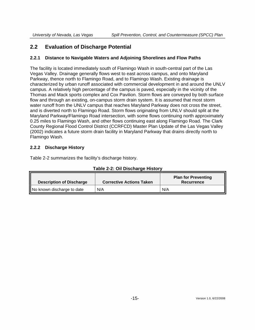
2.2 Evaluation of Discharge Potential 2.2.1 Distance to Navigable Waters and Adjoining Shorelines and Flow Paths The facility is located immediately south of Flamingo Wash in south-central part of the Las Vegas Valley. Drainage generally flows west to east across campus, and onto Maryland Parkway, thence north to Flamingo Road, and to Flamingo Wash. Existing drainage is characterized by urban runoff associated with commercial development in and around the UNLV campus. A relatively high percentage of the campus is paved, especially in the vicinity of the Thomas and Mack sports complex and Cox Pavilion. Storm flows are conveyed by both surface flow and through an existing, on-campus storm drain system. It is assumed that most storm water runoff from the UNLV campus that reaches Maryland Parkway does not cross the street, and is diverted north to Flamingo Road. Storm flows originating from UNLV should split at the Maryland Parkway/Flamingo Road intersection, with some flows continuing north approximately 0.25 miles to Flamingo Wash, and other flows continuing east along Flamingo Road. The Clark County Regional Flood Control District (CCRFCD) Master Plan Update of the Las Vegas Valley (2002) indicates a future storm drain facility in Maryland Parkway that drains directly north to Flamingo Wash. 2.2.2 Discharge History Table 2-2 summarizes the facility’s discharge history.
Table 2-2: Oil Discharge History
Description of Discharge Corrective Actions Taken Plan for Preventing
Recurrence
No known discharge to date N/A N/A
University of Nevada, Las Vegas Spill Prevention, Control, and Countermeasure (SPCC) Plan
Version 1.0, 6/22/2008 -16-
PART 3: Discharge Prevention - General SPCC Provisions
The following measures are recommended to prevent oil discharges during the handling, use, or transfer of oil products at the facility. Oil-handling employees should received training in the proper implementation of these measures.
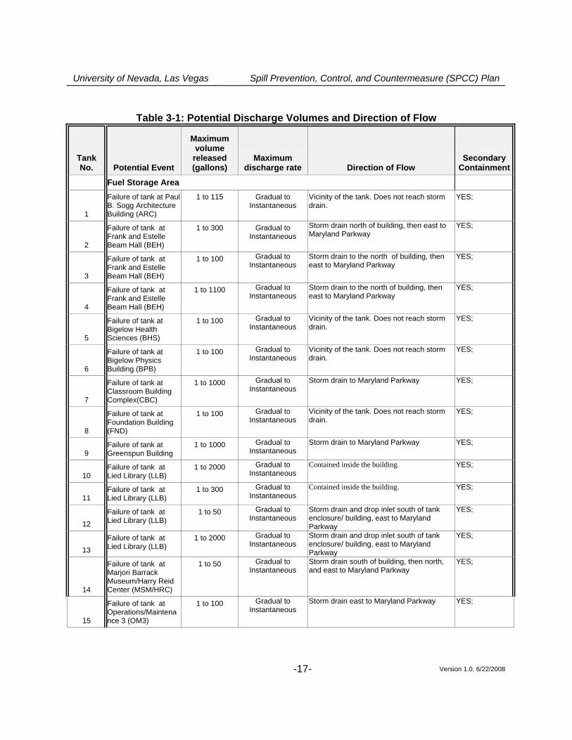
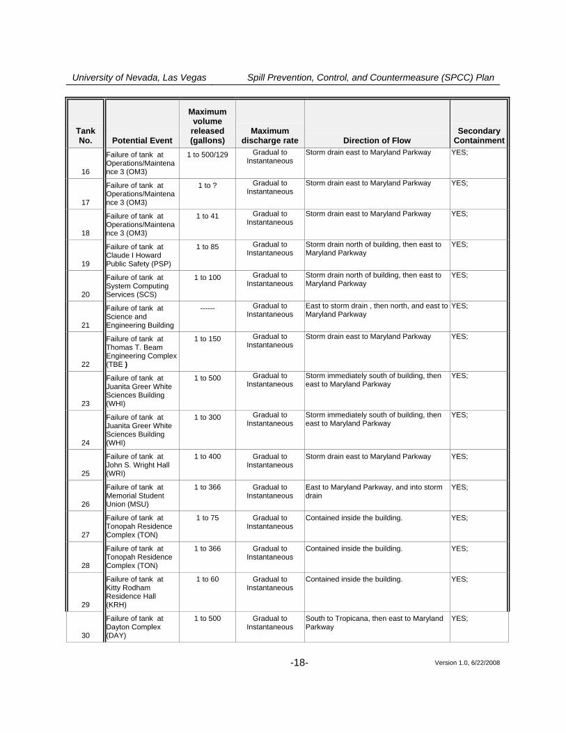
3.1 Compliance with Applicable Requirements (40 CFR 112.7(a)(2)) This facility proposes to use oil/water interceptors and dikes as part of its drainage system to contain oil discharged into the on-campus storm drain system. The interceptor provides environmental protection equivalent to the requirements under 112.8(b)(3) to use ponds, lagoons, or catchment basins to retain oil at the facility in the event of an uncontrolled discharge. As described in Section 3.5 of this Plan, the operational and emergency oil storage capacity of the oil/water interceptor is sufficient to handle the quantity of oil expected to be discharged from a transportation spill on campus. 3.2 Facility Layout Diagram (40 CFR 112.7(a)(3)) Figure A-1 in Appendix A shows the general location of the facility on a U.S. Geological Survey topographic map. Figure A-2 in Appendix A presents a Facility and Drainage Map and the location of storage tanks. As required under 40 CFR 112.7(a)(3), Appendix A indicates the location and content of ASTs, USTs, and transfer stations and connecting piping. Figure A-4 shows individual tank photographs. Tank diagrams were not prepared for the AST’s because the connecting piping could easily be shown on the photos, and because the tanks are distributed throughout campus. 3.3 Spill Reporting (40 CFR 112.7(a)(4)) The discharge notification form included in Appendix I should be completed upon immediate detection of a discharge and prior to reporting a spill to the proper notification contacts. 3.4 Potential Discharge Volumes and Direction of Flow (40 CFR 112.7(b)) Table 3-1 presents expected volume, discharge rate, general direction of flow in the event of equipment failure, and means of secondary containment for different parts of the facility where oil is stored, used, or handled. Potential for discharge on campus is greatest when tanks at various campus locations are being filled.
University of Nevada, Las Vegas Spill Prevention, Control, and Countermeasure (SPCC) Plan
Version 1.0, 6/22/2008 -17-
Table 3-1: Potential Discharge Volumes and Direction of Flow
Tank No. Potential Event
Maximum volume
released (gallons)
Maximum discharge rate Direction of Flow
Secondary Containment
Fuel Storage Area
1
Failure of tank at Paul B. Sogg Architecture Building (ARC)
1 to 115 Gradual to Instantaneous
Vicinity of the tank. Does not reach storm drain.
YES;
2
Failure of tank at Frank and Estelle Beam Hall (BEH)
1 to 300 Gradual to Instantaneous
Storm drain north of building, then east to Maryland Parkway
YES;
3
Failure of tank at Frank and Estelle Beam Hall (BEH)
1 to 100 Gradual to Instantaneous
Storm drain to the north of building, then east to Maryland Parkway
YES;
4
Failure of tank at Frank and Estelle Beam Hall (BEH)
1 to 1100 Gradual to Instantaneous
Storm drain to the north of building, then east to Maryland Parkway
YES;
5
Failure of tank at Bigelow Health Sciences (BHS)
1 to 100 Gradual to Instantaneous
Vicinity of the tank. Does not reach storm drain.
YES;
6
Failure of tank at Bigelow Physics Building (BPB)
1 to 100 Gradual to Instantaneous
Vicinity of the tank. Does not reach storm drain.
YES;
7
Failure of tank at Classroom Building Complex(CBC)
1 to 1000 Gradual to Instantaneous
Storm drain to Maryland Parkway YES;
8
Failure of tank at Foundation Building (FND)
1 to 100 Gradual to Instantaneous
Vicinity of the tank. Does not reach storm drain.
YES;
9 Failure of tank at Greenspun Building
1 to 1000 Gradual to Instantaneous
Storm drain to Maryland Parkway YES;
10 Failure of tank at Lied Library (LLB)
1 to 2000 Gradual to Instantaneous
Contained inside the building. YES;
11 Failure of tank at Lied Library (LLB)
1 to 300 Gradual to Instantaneous
Contained inside the building. YES;
12 Failure of tank at Lied Library (LLB)
1 to 50 Gradual to Instantaneous
Storm drain and drop inlet south of tank enclosure/ building, east to Maryland Parkway
YES;
13 Failure of tank at Lied Library (LLB)
1 to 2000 Gradual to Instantaneous
Storm drain and drop inlet south of tank enclosure/ building, east to Maryland Parkway
YES;
14
Failure of tank at Marjori Barrack Museum/Harry Reid Center (MSM/HRC)
1 to 50 Gradual to Instantaneous
Storm drain south of building, then north, and east to Maryland Parkway
YES;
15
Failure of tank at Operations/Maintenance 3 (OM3)
1 to 100 Gradual to Instantaneous
Storm drain east to Maryland Parkway YES;
University of Nevada, Las Vegas Spill Prevention, Control, and Countermeasure (SPCC) Plan
Version 1.0, 6/22/2008 -18-
Tank No. Potential Event
Maximum volume
released (gallons)
Maximum discharge rate Direction of Flow
Secondary Containment
16
Failure of tank at Operations/Maintenance 3 (OM3)
1 to 500/129 Gradual to Instantaneous
Storm drain east to Maryland Parkway YES;
17
Failure of tank at Operations/Maintenance 3 (OM3)
1 to ? Gradual to Instantaneous
Storm drain east to Maryland Parkway YES;
18
Failure of tank at Operations/Maintenance 3 (OM3)
1 to 41 Gradual to Instantaneous
Storm drain east to Maryland Parkway YES;
19
Failure of tank at Claude I Howard Public Safety (PSP)
1 to 85 Gradual to Instantaneous
Storm drain north of building, then east to Maryland Parkway
YES;
20
Failure of tank at System Computing Services (SCS)
1 to 100 Gradual to Instantaneous
Storm drain north of building, then east to Maryland Parkway
YES;
21
Failure of tank at Science and Engineering Building
------ Gradual to Instantaneous
East to storm drain , then north, and east to Maryland Parkway
YES;
22
Failure of tank at Thomas T. Beam Engineering Complex (TBE )
1 to 150 Gradual to Instantaneous
Storm drain east to Maryland Parkway YES;
23
Failure of tank at Juanita Greer White Sciences Building (WHI)
1 to 500 Gradual to Instantaneous
Storm immediately south of building, then east to Maryland Parkway
YES;
24
Failure of tank at Juanita Greer White Sciences Building (WHI)
1 to 300 Gradual to Instantaneous
Storm immediately south of building, then east to Maryland Parkway
YES;
25
Failure of tank at John S. Wright Hall (WRI)
1 to 400 Gradual to Instantaneous
Storm drain east to Maryland Parkway YES;
26
Failure of tank at Memorial Student Union (MSU)
1 to 366 Gradual to Instantaneous
East to Maryland Parkway, and into storm drain
YES;
27
Failure of tank at Tonopah Residence Complex (TON)
1 to 75 Gradual to Instantaneous
Contained inside the building. YES;
28
Failure of tank at Tonopah Residence Complex (TON)
1 to 366 Gradual to Instantaneous
Contained inside the building. YES;
29
Failure of tank at Kitty Rodham Residence Hall (KRH)
1 to 60 Gradual to Instantaneous
Contained inside the building. YES;
30
Failure of tank at Dayton Complex (DAY)
1 to 500 Gradual to Instantaneous
South to Tropicana, then east to Maryland Parkway
YES;
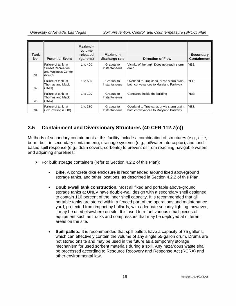
University of Nevada, Las Vegas Spill Prevention, Control, and Countermeasure (SPCC) Plan
Version 1.0, 6/22/2008 -19-
Tank No. Potential Event
Maximum volume
released (gallons)
Maximum discharge rate Direction of Flow
Secondary Containment
31
Failure of tank at Sunset Recreation and Wellness Center (RWC)
1 to 400 Gradual to Instantaneous
Vicinity of the tank. Does not reach storm drain.
YES;
32
Failure of tank at Thomas and Mack (TMC)
1 to 500 Gradual to Instantaneous
Overland to Tropicana, or via storm drain , both conveyances to Maryland Parkway
YES;
33
Failure of tank at Thomas and Mack (TMC)
1 to 100 Gradual to Instantaneous
Contained inside the building YES;
34 Failure of tank at Cox Pavilion (COX)
1 to 380 Gradual to Instantaneous
Overland to Tropicana, or via storm drain , both conveyances to Maryland Parkway
YES;
3.5 Containment and Diversionary Structures (40 CFR 112.7(c)) Methods of secondary containment at this facility include a combination of structures (e.g., dike, berm, built-in secondary containment), drainage systems (e.g., oil/water interceptor), and land-based spill response (e.g., drain covers, sorbents) to prevent oil from reaching navigable waters and adjoining shorelines:
For bulk storage containers (refer to Section 4.2.2 of this Plan):
• Dike. A concrete dike enclosure is recommended around fixed aboveground storage tanks, and other locations, as described in Section 4.2.2 of this Plan.
• Double-wall tank construction. Most all fixed and portable above-ground
storage tanks at UNLV have double-wall design with a secondary shell designed to contain 110 percent of the inner shell capacity. It is recommended that all portable tanks are stored within a fenced part of the operations and maintenance yard, protected from impact by bollards, with adequate security lighting; however, it may be used elsewhere on site. It is used to refuel various small pieces of equipment such as trucks and compressors that may be deployed at different areas on the site.
• Spill pallets. It is recommended that spill pallets have a capacity of 75 gallons,
which can effectively contain the volume of any single 55-gallon drum. Drums are not stored onsite and may be used in the future as a temporary storage mechanism for used sorbent materials during a spill. Any hazardous waste shall be processed according to Resource Recovery and Response Act (RCRA) and other environmental law.
University of Nevada, Las Vegas Spill Prevention, Control, and Countermeasure (SPCC) Plan
Version 1.0, 6/22/2008 -20-
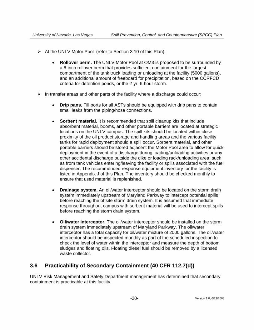
At the UNLV Motor Pool (refer to Section 3.10 of this Plan):
• Rollover berm. The UNLV Motor Pool at OM3 is proposed to be surrounded by
a 6-inch rollover berm that provides sufficient containment for the largest compartment of the tank truck loading or unloading at the facility (5000 gallons), and an additional amount of freeboard for precipitation, based on the CCRFCD criteria for detention ponds, or the 2-yr, 6-hour storm.
In transfer areas and other parts of the facility where a discharge could occur:
• Drip pans. Fill ports for all ASTs should be equipped with drip pans to contain
small leaks from the piping/hose connections.
• Sorbent material. It is recommended that spill cleanup kits that include absorbent material, booms, and other portable barriers are located at strategic locations on the UNLV campus. The spill kits should be located within close proximity of the oil product storage and handling areas and the various facility tanks for rapid deployment should a spill occur. Sorbent material, and other portable barriers should be stored adjacent the Motor Pool area to allow for quick deployment in the event of a discharge during loading/unloading activities or any other accidental discharge outside the dike or loading rack/unloading area, such as from tank vehicles entering/leaving the facility or spills associated with the fuel dispenser. The recommended response equipment inventory for the facility is listed in Appendix J of this Plan. The inventory should be checked monthly to ensure that used material is replenished.
• Drainage system. An oil/water interceptor should be located on the storm drain
system immediately upstream of Maryland Parkway to intercept potential spills before reaching the offsite storm drain system. It is assumed that immediate response throughout campus with sorbent material will be used to intercept spills before reaching the storm drain system.
• Oil/water interceptor. The oil/water interceptor should be installed on the storm
drain system immediately upstream of Maryland Parkway. The oil/water interceptor has a total capacity for oil/water mixture of 2000 gallons. The oil/water interceptor should be inspected monthly as part of the scheduled inspection to check the level of water within the interceptor and measure the depth of bottom sludges and floating oils. Floating diesel fuel should be removed by a licensed waste collector.
3.6 Practicability of Secondary Containment (40 CFR 112.7(d)) UNLV Risk Management and Safety Department management has determined that secondary containment is practicable at this facility.
University of Nevada, Las Vegas Spill Prevention, Control, and Countermeasure (SPCC) Plan
Version 1.0, 6/22/2008 -21-
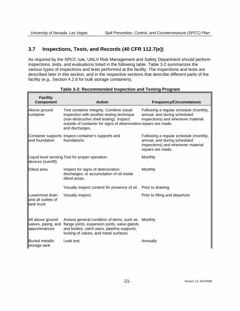
3.7 Inspections, Tests, and Records (40 CFR 112.7(e)) As required by the SPCC rule, UNLV Risk Management and Safety Department should perform inspections, tests, and evaluations listed in the following table. Table 3-2 summarizes the various types of inspections and tests performed at the facility. The inspections and tests are described later in this section, and in the respective sections that describe different parts of the facility (e.g., Section 4.2.6 for bulk storage containers).
Table 3-2: Recommended Inspection and Testing Program
Facility Component Action Frequency/Circumstances
Above ground container
Test container integrity. Combine visual inspection with another testing technique (non-destructive shell testing). Inspect outside of container for signs of deterioration and discharges.
Following a regular schedule (monthly, annual, and during scheduled inspections) and whenever material repairs are made.
Container supports and foundation
Inspect container’s supports and foundations.
Following a regular schedule (monthly, annual, and during scheduled inspections) and whenever material repairs are made.
Liquid level sensing devices (overfill)
Test for proper operation. Monthly
Diked area Inspect for signs of deterioration, discharges, or accumulation of oil inside diked areas. Visually inspect content for presence of oil.
Monthly Prior to draining
Lowermost drain and all outlets of tank truck
Visually inspect. Prior to filling and departure
All above ground valves, piping, and appurtenances
Assess general condition of items, such as flange joints, expansion joints, valve glands and bodies, catch pans, pipeline supports, locking of valves, and metal surfaces.
Monthly
Buried metallic storage tank
Leak test. Annually
University of Nevada, Las Vegas Spill Prevention, Control, and Countermeasure (SPCC) Plan
Version 1.0, 6/22/2008 -22-
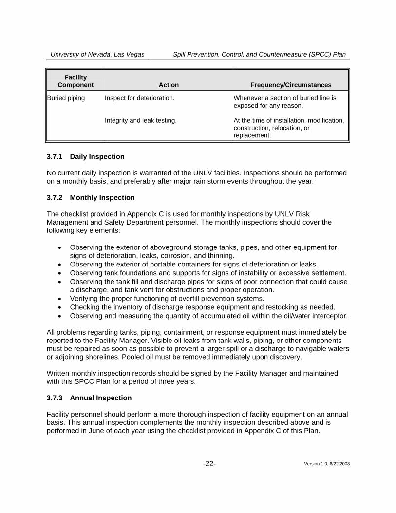
Facility Component Action Frequency/Circumstances
Buried piping Inspect for deterioration. Integrity and leak testing.
Whenever a section of buried line is exposed for any reason. At the time of installation, modification, construction, relocation, or replacement.
3.7.1 Daily Inspection No current daily inspection is warranted of the UNLV facilities. Inspections should be performed on a monthly basis, and preferably after major rain storm events throughout the year. 3.7.2 Monthly Inspection The checklist provided in Appendix C is used for monthly inspections by UNLV Risk Management and Safety Department personnel. The monthly inspections should cover the following key elements:
• Observing the exterior of aboveground storage tanks, pipes, and other equipment for signs of deterioration, leaks, corrosion, and thinning.
• Observing the exterior of portable containers for signs of deterioration or leaks. • Observing tank foundations and supports for signs of instability or excessive settlement. • Observing the tank fill and discharge pipes for signs of poor connection that could cause
a discharge, and tank vent for obstructions and proper operation. • Verifying the proper functioning of overfill prevention systems. • Checking the inventory of discharge response equipment and restocking as needed. • Observing and measuring the quantity of accumulated oil within the oil/water interceptor.
All problems regarding tanks, piping, containment, or response equipment must immediately be reported to the Facility Manager. Visible oil leaks from tank walls, piping, or other components must be repaired as soon as possible to prevent a larger spill or a discharge to navigable waters or adjoining shorelines. Pooled oil must be removed immediately upon discovery. Written monthly inspection records should be signed by the Facility Manager and maintained with this SPCC Plan for a period of three years. 3.7.3 Annual Inspection Facility personnel should perform a more thorough inspection of facility equipment on an annual basis. This annual inspection complements the monthly inspection described above and is performed in June of each year using the checklist provided in Appendix C of this Plan.
University of Nevada, Las Vegas Spill Prevention, Control, and Countermeasure (SPCC) Plan
Version 1.0, 6/22/2008 -23-
The annual inspection is preferably performed after a large storm event in order to verify the imperviousness and/or proper functioning of drainage control systems such as the dike, rollover berm, control valves, and the oil/water interceptor. Written annual inspection records are signed by the Facility Manager and maintained with this SPCC Plan for a period of three years. 3.7.4 Periodic Integrity Testing In addition to the above monthly and annual inspections by facility personnel, all tanks should be periodically evaluated by an outside certified tank inspector following the Steel Tank Institute (STI) Standard for the Inspection of Aboveground Storage Tanks, SP-001, 2005 version, as
escribed in Section 4.2.6 of this Plan. d 3.8 Personnel, Training, and Discharge Prevention Procedures
(40 CFR 112.7(f)) The Facility Manager is the facility designee and is responsible for oil discharge prevention, control, and response preparedness activities at this facility. UNLV Risk Management and Safety Department management should develop instruction to oil-handling facility personnel in the operation and maintenance of oil pollution prevention equipment, discharge procedure protocols, applicable pollution control laws, rules and regulations, general facility operations, and the content of this SPCC Plan. Any new facility personnel with oil-handling responsibilities should be provided with this same training prior to being involved in any oil operation. Annual discharge prevention briefings should be held by the Facility Manager for all facility personnel involved in oil operations. The briefings should be aimed at ensuring continued understanding and adherence to the discharge prevention procedures presented in the SPCC Plan. The briefings should highlight and describe known discharge events or failures, malfunctioning components, and recently implemented precautionary measures and best practices. Facility operators and other personnel should have the opportunity during the briefings to share recommendations concerning health, safety, and environmental issues encountered during facility operations. A simulation of an on-site vehicular discharge should be conducted, and future training exercises should be periodically held to prepare for possible discharge responses. Records of the briefings and discharge prevention training should be kept on the form shown in Appendix E and maintained with this SPCC Plan for a period of three years.
University of Nevada, Las Vegas Spill Prevention, Control, and Countermeasure (SPCC) Plan
Version 1.0, 6/22/2008 -24-
3.9 Security (40 CFR 112.7(g)) Most facilities at UNLV are surrounded by a minimum of 6-ft tall steel security fencing, or block wall, or are completely contained inside a utility room. The 2000 gallon tank at the south side of the Lied Library is surrounded by walls and steel fencing. All drain valves for containment areas should be locked in the closed position to prevent unauthorized opening. Water draw valves on the storage tanks should be maintained in the closed position to prevent unauthorized opening via locks, and are required to be locked. Keys for all locked valves should be kept in the appropriate office for each facility. Copies of all keys should be made and provided to Risk Management and Safety. Tank #4 at BEH will require security fencing, whereas Tank #31 at the Thomas & Mack will require both security fencing and improvements. Lights are in place at various locations throughout the UNLV campus. The electrical starter controls for the oil pumps, including the fuel dispenser, are located in the secure area adjacent all the tanks. The closet is locked when the pumps are not in use. The maintenance shop is locked when the facility is unattended. The facility should securely cap or blank-flange the loading/unloading connections of facility piping when not in service or when in standby service for an extended period of time, or when piping is emptied of liquid content either by draining or by inert gas pressure. 3.10 Tank Truck Loading/Unloading Rack Requirements (40 CFR 112.7(h)) The potential for discharges during tank truck loading and unloading operations is of particular concern at this facility. UNLV Risk Management and Safety Department management is committed to ensuring the safe transfer of material to and from storage tanks. The following measures should be implemented to prevent oil discharges during tank truck loading and unloading operations. 3.10.1 Secondary Containment (40 CFR 112.7(h)(1)) The Motor Pool area should be surrounded with a 6-inch rollover asphalt berm that provides secondary containment in the event of a discharge during transfer operations. The secondary containment berm should be designed to address the more stringent rack containment requirements of 40 CFR 112.7(h), which requires that the berm be sufficient to contain the capacity of the largest compartment, plus freeboard for precipitation. The curbed area should provide a catchment capacity of 5000 gallons, which is capable of containing the largest volume of the largest UST at the Motor Pool site. To minimize direct exposure to rain, and facilitate the cleanup of small spills that may occur during loading/unloading operations, the Motor Pool area is partially covered by a roof.
University of Nevada, Las Vegas Spill Prevention, Control, and Countermeasure (SPCC) Plan
Version 1.0, 6/22/2008 -25-
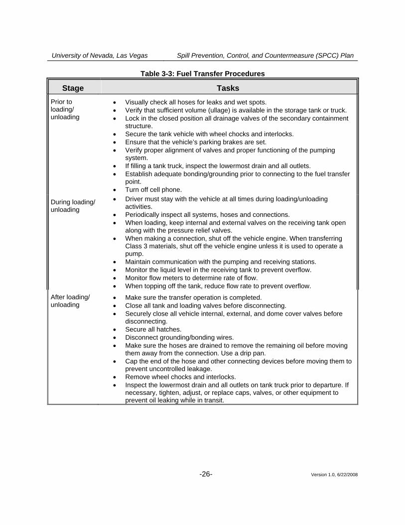
The area should be graded to direct the flow of oil or water away from the vehicle, and the low point of the curbed area is fitted with a gate valve that is normally kept closed and locked. The key for that lock is kept in the main office. The berm should be drained by UNLV personnel after verifying that the retained water is free of oil. The accumulated water should be released to the onsite storm drain system and the oil/water interceptor. The drain valve should be closed and locked following drainage. 3.10.2 Loading/Unloading Procedures (40 CFR 112.7(h)(2) and (3)) All suppliers must meet the minimum requirements and regulations for tank truck loading/unloading established by the U.S. Department of Transportation. UNLV Risk Management and Safety Department ensures that the vendor understands the site layout, knows the protocol for entering the facility and unloading product, and has the necessary equipment to respond to a discharge from the vehicle or fuel delivery hose. The Facility Manager or his/her designee supervises oil deliveries for all new suppliers, and periodically observes deliveries for existing, approved suppliers. All loading and unloading of tank vehicles takes place only in the designated loading rack/unloading area. Vehicle filling operations should be performed by facility personnel trained in proper discharge prevention procedures. The truck driver or facility personnel remain with the vehicle at all times while fuel is being transferred. Transfer operations are performed according to the minimum procedures outlined in Table 3-3. This table is also posted next to the loading/unloading point.
University of Nevada, Las Vegas Spill Prevention, Control, and Countermeasure (SPCC) Plan
Version 1.0, 6/22/2008 -26-
Table 3-3: Fuel Transfer Procedures
Stage Tasks Prior to loading/ unloading
• Visually check all hoses for leaks and wet spots. • Verify that sufficient volume (ullage) is available in the storage tank or truck. • Lock in the closed position all drainage valves of the secondary containment
structure. • Secure the tank vehicle with wheel chocks and interlocks. • Ensure that the vehicle’s parking brakes are set. • Verify proper alignment of valves and proper functioning of the pumping
system. • If filling a tank truck, inspect the lowermost drain and all outlets. • Establish adequate bonding/grounding prior to connecting to the fuel transfer
point. • Turn off cell phone.
During loading/ unloading
• Driver must stay with the vehicle at all times during loading/unloading activities.
• Periodically inspect all systems, hoses and connections. • When loading, keep internal and external valves on the receiving tank open
along with the pressure relief valves. • When making a connection, shut off the vehicle engine. When transferring
Class 3 materials, shut off the vehicle engine unless it is used to operate a pump.
• Maintain communication with the pumping and receiving stations. • Monitor the liquid level in the receiving tank to prevent overflow. • Monitor flow meters to determine rate of flow. • When topping off the tank, reduce flow rate to prevent overflow.
After loading/ unloading
• Make sure the transfer operation is completed. • Close all tank and loading valves before disconnecting. • Securely close all vehicle internal, external, and dome cover valves before
disconnecting. • Secure all hatches. • Disconnect grounding/bonding wires. • Make sure the hoses are drained to remove the remaining oil before moving
them away from the connection. Use a drip pan. • Cap the end of the hose and other connecting devices before moving them to
prevent uncontrolled leakage. • Remove wheel chocks and interlocks. • Inspect the lowermost drain and all outlets on tank truck prior to departure. If
necessary, tighten, adjust, or replace caps, valves, or other equipment to prevent oil leaking while in transit.
University of Nevada, Las Vegas Spill Prevention, Control, and Countermeasure (SPCC) Plan
Version 1.0, 6/22/2008 -27-
3.11 Brittle Fracture Evaluation (40 CFR 112.7(i)) In the event that any tank undergoes a repair, alteration, reconstruction, or change in service that might affect the risk of a discharge or failure, the container will be evaluated for risk of discharge or failure, following API-653 or an equivalent approach, and corrective action will be taken as necessary. All UNLV organizations that conduct repairs on tanks will notify RMS who will ensure that those repairs are accomplished and done with full consideration for and attention to the requirements to ensure there are no spills. RMS will ensure that all Local and Applicable requirements are met for bulk storage and UST’s. 3.12 Conformance with State and Local Applicable Requirements (40 CFR
112.7(j)) All bulk storage tanks at this facility are registered with local authorities and have current certificates of registration and special use permits required by the local fire code. Both USTs at the Motor Pool meet all requirements of NDEP UST regulation, including cathodic protection, double-wall construction, and monitoring systems.
University of Nevada, Las Vegas Spill Prevention, Control, and Countermeasure (SPCC) Plan
Version 1.0, 6/22/2008 -28-
PART 4: Discharge Prevention – SPCC Provisions for Onshore Facilities (Excluding Production Facilities)
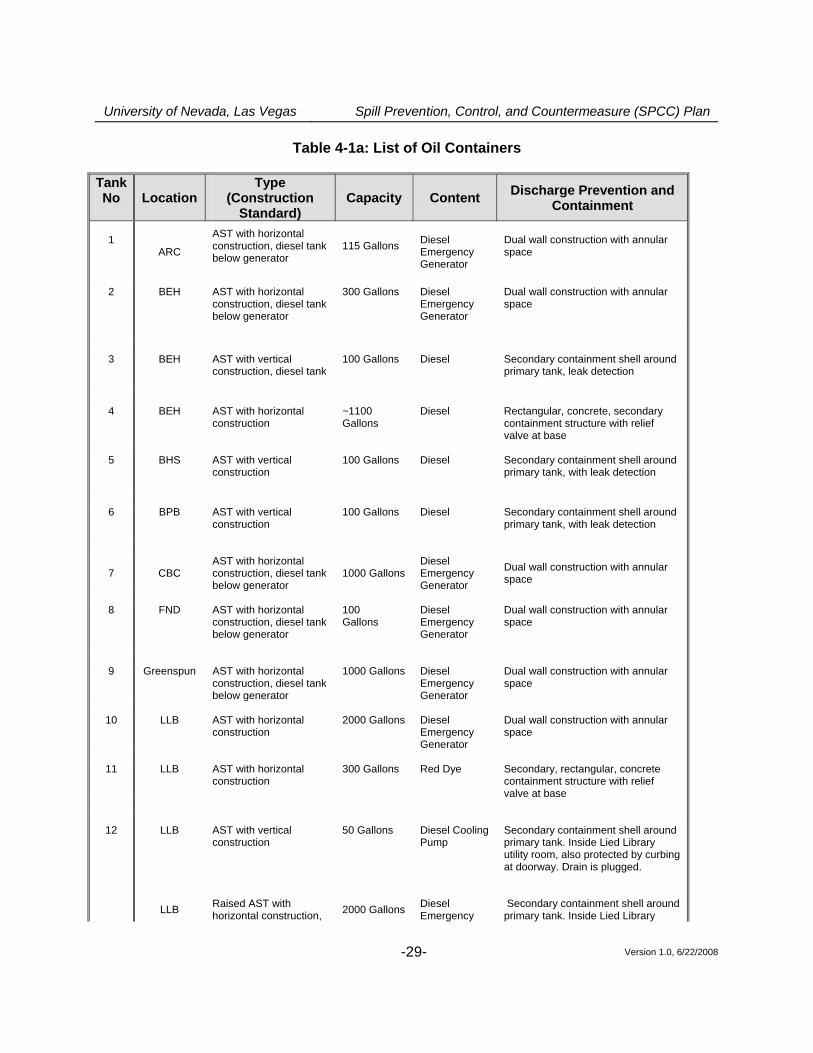
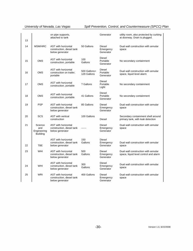
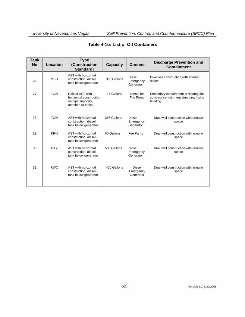
4.1 Facility Drainage (40 CFR 112.8(b)) Drainage from the UNLV campus is generally from west to east. An onsite storm drain intercepts storm flows and drains to Maryland Parkway. Potential releases of oil from most parts of campus generally do not have the potential to be captured by the storm drain system because of the distance of overland flow to the nearest drop inlet. The proposed location of the oil/water interceptor is designed to intercept diesel fuel from the Lied Library tank before being captured by the onsite storm drains system before reaching Maryland Parkway. The proposed oil/water interceptor downstream of Tank #10 at the Lied Library should intercept spills before reaching the drop inlet outside the block wall south of the tank location. Drainage events are recorded in the log included in Appendix D to this SPCC Plan. A proposed dike at OM3 should be restrained by a manually-operated gate valve to prevent a discharge from leaving the portable generator site. The gate valve should normally be sealed closed, except when draining the secondary containment structure. The content of the secondary containment dike is inspected by facility personnel prior to draining to ensure that only oil-free water is allowed to enter the facility storm water drainage system. The bypass valve should be opened and resealed under direct personnel supervision. Drainage events are recorded in the log included in Appendix D to this SPCC Plan. A proposed rollover berm at the Motor Pool is restrained by a manually-operated gate valve to prevent a discharge from leaving the Motor Pool site. The gate valve should normally be sealed closed, except when draining the secondary containment structure. The content of the secondary containment dike is inspected by facility personnel prior to draining to ensure that only oil-free water is allowed to enter the facility storm water drainage system. The bypass valve should be opened and resealed under direct personnel supervision. Drainage events are recorded in the log included in Appendix D to this SPCC Plan. Any potential discharge from ASTs should be restrained by secondary containment structures or sorbent material. Discharges at the Motor Pool occurring during loading/unloading operations should be restrained by the rollover berm. The Lied Library includes an oil/water interceptor, which is used as containment for spill of the existing 2000 gallon tank. Discharges outside the Motor Pool, Lied Library area, or other areas, should be intercepted by other methods such as sorbent materials. pumped out. 4.2 Bulk Storage Containers (40 CFR 112.8(c)) Table 4-1 summarizes the construction, volume, and content of bulk storage containers at UNLV facility.
University of Nevada, Las Vegas Spill Prevention, Control, and Countermeasure (SPCC) Plan
Version 1.0, 6/22/2008 -29-
Table 4-1a: List of Oil Containers Tank No Location
Type (Construction
Standard) Capacity Content Discharge Prevention and
Containment 1
ARC
AST with horizontal construction, diesel tank below generator
115 Gallons
Diesel Emergency Generator
Dual wall construction with annular space
2 BEH AST with horizontal
construction, diesel tank below generator
300 Gallons Diesel Emergency Generator
Dual wall construction with annular space
3 BEH
AST with vertical construction, diesel tank
100 Gallons Diesel Secondary containment shell around primary tank, leak detection
4 BEH AST with horizontal
construction ~1100 Gallons
Diesel Rectangular, concrete, secondary containment structure with relief valve at base
5 BHS AST with vertical
construction 100 Gallons Diesel Secondary containment shell around
primary tank, with leak detection
6 BPB AST with vertical construction
100 Gallons Diesel Secondary containment shell around primary tank, with leak detection
7 CBC
AST with horizontal construction, diesel tank below generator
1000 Gallons Diesel Emergency Generator
Dual wall construction with annular space
8 FND AST with horizontal
construction, diesel tank below generator
100 Gallons
Diesel Emergency Generator
Dual wall construction with annular space
9 Greenspun AST with horizontal construction, diesel tank below generator
1000 Gallons Diesel Emergency Generator
Dual wall construction with annular space
10 LLB AST with horizontal
construction 2000 Gallons Diesel
Emergency Generator
Dual wall construction with annular space
11 LLB AST with horizontal
construction 300 Gallons Red Dye Secondary, rectangular, concrete
containment structure with relief valve at base
12 LLB AST with vertical construction
50 Gallons Diesel Cooling Pump
Secondary containment shell around primary tank. Inside Lied Library utility room, also protected by curbing at doorway. Drain is plugged.
LLB Raised AST with
horizontal construction, 2000 Gallons Diesel Emergency
Secondary containment shell around primary tank. Inside Lied Library
University of Nevada, Las Vegas Spill Prevention, Control, and Countermeasure (SPCC) Plan
Version 1.0, 6/22/2008 -30-
13
on pipe supports, attached to tank
Generator utility room, also protected by curbing at doorway. Drain is plugged.
14 MSM/HRC AST with horizontal
construction, diesel tank below generator
50 Gallons Diesel Emergency Generator
Dual wall construction with annular space
15 OM3 AST with horizontal construction, portable
100 Gallons
Diesel Portable Generator
No secondary containment
16 OM3 AST with horizontal construction on trailer, portable
500 Gallons+ 129 Gallons
Diesel Portable Generator
Dual wall construction with annular space, liquid level alarm
17 OM3 AST with horizontal construction, portable ? Gallons
Diesel Portable Light
No secondary containment
18 OM3 AST with horizontal construction, portable 41 Gallons
Diesel Portable Generator
No secondary containment
19 PSP
AST with horizontal construction, diesel tank below generator
85 Gallons Diesel Emergency Generator
Dual wall construction with annular space
20 SCS AST with vertical
construction 100 Gallons
Diesel Secondary containment shell around primary tank, with leak detection
21 Science
and Engineering
Building
AST with horizontal construction, diesel tank below generator
------
Diesel Emergency Generator
Dual wall construction with annular space
22 TBE
AST with horizontal construction, diesel tank below generator
150 Gallons
Diesel Emergency Generator
Dual wall construction with annular space
23 WHI AST with horizontal
construction, diesel tank below generator
500 Gallons
Diesel Emergency Generator
Dual wall construction with annular space, liquid level control and alarm
24 WHI AST with horizontal construction, diesel tank below generator
300 Gallons
Diesel Emergency Generator
Dual wall construction with annular space
25 WRI AST with horizontal
construction, diesel tank below generator
400 Gallons Diesel Emergency Generator
Dual wall construction with annular space
University of Nevada, Las Vegas Spill Prevention, Control, and Countermeasure (SPCC) Plan
Version 1.0, 6/22/2008 -31-
Table 4-1b: List of Oil Containers
Tank No Location
Type (Construction
Standard) Capacity Content Discharge Prevention and
Containment
26 MSU AST with horizontal construction, diesel tank below generator
366 Gallons
Diesel Emergency Generator
Dual wall construction with annular space
27 TON Raised AST with
horizontal construction on pipe supports, attached to tanks
75 Gallons Diesel for Fire Pump
Secondary containment is rectangular, concrete containment structure, inside building
28 TON
AST with horizontal construction, diesel tank below generator
366 Gallons Diesel Emergency Generator
Dual wall construction with annular space
29 KRH AST with horizontal
construction, diesel tank below generator
60 Gallons Fire Pump Dual wall construction with annular space
30 DAY AST with horizontal
construction, diesel tank below generator
500 Gallons Diesel Emergency Generator
Dual wall construction with annular space
31 RWC AST with horizontal construction, diesel tank below generator
400 Gallons Diesel Emergency Generator
Dual wall construction with annular space
University of Nevada, Las Vegas Spill Prevention, Control, and Countermeasure (SPCC) Plan
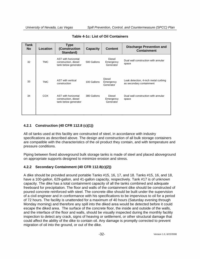
Version 1.0, 6/22/2008 -32-
Table 4-1c: List of Oil Containers Tank No Location
Type (Construction
Standard) Capacity Content Discharge Prevention and
Containment
32
TMC AST with horizontal construction, diesel tank below generator
500 Gallons Diesel
Emergency Generator
Dual wall construction with annular space
33
TMC AST with vertical construction 100 Gallons
Diesel Emergency Generator
Leak detection, 4-inch metal curbing as secondary containment
34 COX AST with horizontal
construction, diesel tank below generator
380 Gallons Diesel Emergency Generator
Dual wall construction with annular space
4.2.1 Construction (40 CFR 112.8 (c)(1)) All oil tanks used at this facility are constructed of steel, in accordance with industry specifications as described above. The design and construction of all bulk storage containers are compatible with the characteristics of the oil product they contain, and with temperature and pressure conditions. Piping between fixed aboveground bulk storage tanks is made of steel and placed aboveground on appropriate supports designed to minimize erosion and stress. 4.2.2 Secondary Containment (40 CFR 112.8(c)(2)) A dike should be provided around portable Tanks #15, 16, 17, and 18. Tanks #15, 16, and 18, have a 100-gallon, 629-gallon, and 41-gallon capacity, respectively. Tank #17 is of unknown capacity. The dike has a total containment capacity of all the tanks combined and adequate freeboard for precipitation. The floor and walls of the containment dike should be constructed of poured concrete reinforced with steel. The concrete dike should be built under the supervision of a civil engineer and in conformance with his specifications to be impervious to oil for a period of 72 hours. The facility is unattended for a maximum of 40 hours (Saturday evening through Monday morning) and therefore any spill into the diked area would be detected before it could escape the diked area. The surface of the concrete floor, the inside and outside of the walls, and the interface of the floor and walls, should be visually inspected during the monthly facility inspection to detect any crack, signs of heaving or settlement, or other structural damage that could affect the ability of the dike to contain oil. Any damage is promptly corrected to prevent migration of oil into the ground, or out of the dike.
University of Nevada, Las Vegas Spill Prevention, Control, and Countermeasure (SPCC) Plan
Version 1.0, 6/22/2008 -33-
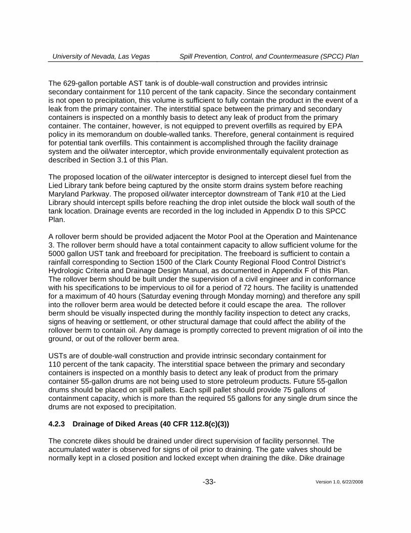
The 629-gallon portable AST tank is of double-wall construction and provides intrinsic secondary containment for 110 percent of the tank capacity. Since the secondary containment is not open to precipitation, this volume is sufficient to fully contain the product in the event of a leak from the primary container. The interstitial space between the primary and secondary containers is inspected on a monthly basis to detect any leak of product from the primary container. The container, however, is not equipped to prevent overfills as required by EPA policy in its memorandum on double-walled tanks. Therefore, general containment is required for potential tank overfills. This containment is accomplished through the facility drainage system and the oil/water interceptor, which provide environmentally equivalent protection as described in Section 3.1 of this Plan. The proposed location of the oil/water interceptor is designed to intercept diesel fuel from the Lied Library tank before being captured by the onsite storm drains system before reaching Maryland Parkway. The proposed oil/water interceptor downstream of Tank #10 at the Lied Library should intercept spills before reaching the drop inlet outside the block wall south of the tank location. Drainage events are recorded in the log included in Appendix D to this SPCC Plan. A rollover berm should be provided adjacent the Motor Pool at the Operation and Maintenance 3. The rollover berm should have a total containment capacity to allow sufficient volume for the 5000 gallon UST tank and freeboard for precipitation. The freeboard is sufficient to contain a rainfall corresponding to Section 1500 of the Clark County Regional Flood Control District’s Hydrologic Criteria and Drainage Design Manual, as documented in Appendix F of this Plan. The rollover berm should be built under the supervision of a civil engineer and in conformance with his specifications to be impervious to oil for a period of 72 hours. The facility is unattended for a maximum of 40 hours (Saturday evening through Monday morning) and therefore any spill into the rollover berm area would be detected before it could escape the area. The rollover berm should be visually inspected during the monthly facility inspection to detect any cracks, signs of heaving or settlement, or other structural damage that could affect the ability of the rollover berm to contain oil. Any damage is promptly corrected to prevent migration of oil into the ground, or out of the rollover berm area. USTs are of double-wall construction and provide intrinsic secondary containment for 110 percent of the tank capacity. The interstitial space between the primary and secondary containers is inspected on a monthly basis to detect any leak of product from the primary container 55-gallon drums are not being used to store petroleum products. Future 55-gallon drums should be placed on spill pallets. Each spill pallet should provide 75 gallons of containment capacity, which is more than the required 55 gallons for any single drum since the drums are not exposed to precipitation. 4.2.3 Drainage of Diked Areas (40 CFR 112.8(c)(3)) The concrete dikes should be drained under direct supervision of facility personnel. The accumulated water is observed for signs of oil prior to draining. The gate valves should be normally kept in a closed position and locked except when draining the dike. Dike drainage
University of Nevada, Las Vegas Spill Prevention, Control, and Countermeasure (SPCC) Plan
Version 1.0, 6/22/2008 -34-
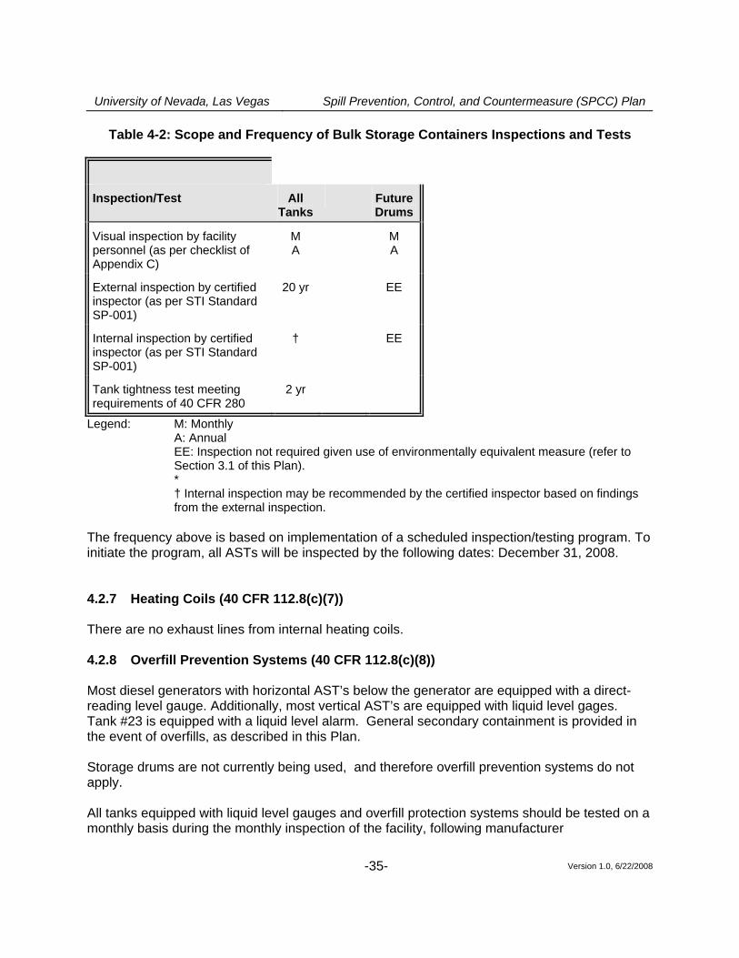
events are recorded on the form included in Appendix D of this Plan; records are maintained at the facility for at least three years. 4.2.4 Corrosion Protection (40 CFR 112.8(c)(4)) Both metallic underground storage tanks, which is subject to the requirements of 40 CFR part 112, should be coated and cathodically protected to prevent corrosion and leakage into the ground. Pressure testing should be performed on both buried storage tanks every two years following the requirements of 40 CFR part 280. The cathodic protection system should be tested annually to verify its efficacy. Cathodic protection should be provided for both tanks in accordance with 40 CFR part 280 and meets the requirements of 40 CFR part 112. Records of pressure tests should be kept for at least three years. 4.2.5 Partially Buried and Bunkered Storage Tanks (40 CFR 112.8(c)(5)) This section is not applicable since there are no partially buried or bunkered storage tanks at this facility. 4.2.6 Inspections and Tests (40 CFR 112.8(c)(6)) Visual inspections of ASTs by facility personnel should be performed according to the procedure described in this SPCC Plan. Leaks from tank seams, gaskets, rivets, and bolts should be promptly corrected. Records of inspections and tests should be signed by the inspector and kept at the facility for at least three years. The scope and schedule of certified inspections and tests performed on the facility’s ASTs are specified in STI Standard SP-001. The external inspection should include ultrasonic testing of the shell, as specified in the standard, or if recommended by the certified tank inspector to assess the integrity of the tank for continued oil storage. Records of certified tank inspections are kept at the facility for at least three years. Shell test comparison records are retained for the life of the tanks. Table 4-2 summarizes inspections and tests performed on bulk storage containers (“EE” indicates that an environmentally equivalent measure is implemented in place of the inspection/test, as discussed in Section 3.1 of this Plan).
University of Nevada, Las Vegas Spill Prevention, Control, and Countermeasure (SPCC) Plan
Version 1.0, 6/22/2008 -35-
Table 4-2: Scope and Frequency of Bulk Storage Containers Inspections and Tests
Inspection/Test All Tanks
FutureDrums
Visual inspection by facility personnel (as per checklist of Appendix C)
M A
M A
External inspection by certified inspector (as per STI Standard SP-001)
20 yr EE
Internal inspection by certified inspector (as per STI Standard SP-001)
† EE
Tank tightness test meeting requirements of 40 CFR 280
2 yr
Legend: M: Monthly A: Annual
EE: Inspection not required given use of environmentally equivalent measure (refer to Section 3.1 of this Plan). * † Internal inspection may be recommended by the certified inspector based on findings from the external inspection.
The frequency above is based on implementation of a scheduled inspection/testing program. To initiate the program, all ASTs will be inspected by the following dates: December 31, 2008. 4.2.7 Heating Coils (40 CFR 112.8(c)(7)) There are no exhaust lines from internal heating coils. 4.2.8 Overfill Prevention Systems (40 CFR 112.8(c)(8)) Most diesel generators with horizontal AST’s below the generator are equipped with a direct-reading level gauge. Additionally, most vertical AST’s are equipped with liquid level gages. Tank #23 is equipped with a liquid level alarm. General secondary containment is provided in the event of overfills, as described in this Plan. Storage drums are not currently being used, and therefore overfill prevention systems do not apply. All tanks equipped with liquid level gauges and overfill protection systems should be tested on a monthly basis during the monthly inspection of the facility, following manufacturer
University of Nevada, Las Vegas Spill Prevention, Control, and Countermeasure (SPCC) Plan
Version 1.0, 6/22/2008 -36-
recommendations. Venting capacity is suitable for the fill and withdrawal rates. Facility personnel should be present throughout the filling operations to monitor the product level in the tanks. 4.2.9 Effluent Treatment Facilities (40 CFR 112.8(c)(9)) There are no effluent treatment facilities onsite.4.2.10 4.2.10 Visible Discharges (40 CFR 112.8(c)(10)) Visible discharges from any container or appurtenance – including seams, gaskets, piping, pumps, valves, rivets, and bolts should be quickly corrected upon discovery. Oil should be promptly removed from all diked areas and disposed of according to the waste disposal method described in Part 5 of this Plan. 4.2.11 Mobile and Portable Containers (40 CFR 112.8(c)(11)) Tank #16 is of double-wall design, which provides for adequate secondary containment in the event of leaks in the primary container shell. The interstitial space will be monitored monthly for signs of leakage. Small portable generators should be stored inside OM3 in a containment dike. Any discharged material is quickly contained and cleaned up using sorbent pads and appropriate cleaning products. 4.3 Transfer Operations, Pumping, and In-Plant Processes
(40 CFR 112.8(d)) Transfer operations at this facility include:
• The transfer of diesel fuel to the 5,000-gallon and 2,000-gallon UST’s at the UNLV Motor Pool, and
• The transfer of diesel fuel to the various other AST’s located throughout the UNLV campus.
All buried piping at this facility should be cathodically protected against corrosion and should be provided with a protective wrapping and coating. When a section of buried line is exposed, it should be carefully examined for deterioration. If corrosion damage is found, additional examination and corrective action must be taken as deemed appropriate considering the magnitude of the damage. Additionally, UNLV Risk Management and Safety Department should conduct integrity and leak testing of buried piping at the time of installation, modification, construction, relocation, or replacement. Records of all tests are kept at the facility for at least three years.
University of Nevada, Las Vegas Spill Prevention, Control, and Countermeasure (SPCC) Plan
Version 1.0, 6/22/2008 -37-
Lines that are not in service or are on standby for an extended period of time are capped or blank-flanged and marked as to their origin. All pipe supports are designed to minimize abrasion and corrosion and to allow for expansion and contraction. Pipe supports should be visually inspected during the monthly inspection of the facility. All aboveground piping and valves are examined monthly to assess their condition. Inspection includes aboveground valves, piping, appurtenances, expansion joints, valve glands and bodies, catch pans, pipeline supports, locking of valves, and metal surfaces. Observations are noted on the monthly inspection checklist provided in this Plan. Warning signs should be posted at appropriate locations throughout the facility to prevent vehicles from damaging aboveground piping and appurtenances. Most of the aboveground piping should be located within areas that are not accessible to vehicular traffic (e.g., inside diked area). Brightly painted bollards should be placed where needed to prevent vehicular collisions with equipment.
University of Nevada, Las Vegas Spill Prevention, Control, and Countermeasure (SPCC) Plan
Version 1.0, 6/22/2008 -38-
Part 5: Discharge Response
This section describes the response and cleanup procedures in the event of an oil discharge. The uncontrolled discharge of oil to groundwater, surface water, or soil is prohibited by state and possibly federal laws. Immediate action must be taken to control, contain, and recover discharged product. In general, the following steps should be taken:
• Eliminate potential spark sources; • If possible and safe to do so, identify and shut down source of the discharge to stop the
flow; • Contain the discharge with sorbents, berms, fences, trenches, sandbags, or other
material; • Contact the Facility Manager or his/her alternate; • Contact regulatory authorities and the response organization; and • Collect and dispose of recovered products according to regulation.
For the purpose of establishing appropriate response procedures, this SPCC Plan classifies discharges as either “minor” or “major,” depending on the volume and characteristics of the material released. A list of Emergency Contacts is provided in Appendix H. The list should be posted at prominent locations throughout the facility. A list of discharge response material kept at the facility is included in Appendix J. 5.1 Response to a Minor Discharge A “minor” discharge is defined as one that poses no significant harm (or threat) to human health and safety or to the environment. Minor discharges are generally those where:
• The quantity of product discharged is small (e.g., may involve less than 25 gallons of oil); • Discharged material is easily stopped and controlled at the time of the discharge; • Discharge is localized near the source; • Discharged material is not likely to reach water; • There is little risk to human health or safety; and • There is little risk of fire or explosion.
University of Nevada, Las Vegas Spill Prevention, Control, and Countermeasure (SPCC) Plan
Version 1.0, 6/22/2008 -39-
Minor discharges can usually be cleaned up by UNLV Risk Management and Safety Department personnel. The following guidelines apply:
• Immediately notify the Facility Manager. • Under the direction of the Facility Manager, contain the discharge with discharge
response materials and equipment. Place discharge debris in properly labeled waste containers.
• The Facility Manager will complete the discharge notification form (Appendix I) and attach a copy to this SPCC Plan.
• If the discharge involves more than 25 gallons of oil, the Facility Manager will call the Nevada Division of Environmental Protection (NDEP)
5.2 Response to a Major Discharge A “major” discharge is defined as one that cannot be safely controlled or cleaned up by facility personnel, such as when:
• The discharge is large enough to spread beyond the immediate discharge area; • The discharged material enters the onsite storm drain system; • The discharge requires special equipment or training to clean up; • The discharged material poses a hazard to human health or safety; or • There is a danger of fire or explosion.
In the event of a major discharge, the following guidelines apply:
• All workers must immediately evacuate the discharge site via the designated exit routes and move to the designated staging areas at a safe distance from the discharge. Exit routes are included on the facility diagram and posted in the maintenance building, in the office building, and on the outside wall of the outside shed that contains the spill response equipment.
• If the Facility Manager is not present at the facility, the senior on-site person notifies the Facility Manager of the discharge and has authority to initiate notification and response. Certain notifications are dependent on the circumstances and type of discharge. For example, if oil reaches a sanitary sewer, the publicly owned treatment works (POTW) should be notified immediately. A discharge that threatens Flamingo Wash may require immediate notification to downstream users such as the Clark County Regional Flood Control District.The Facility Manager (or senior on-site person) must call for medical assistance if workers are injured.
• The Facility Manager (or senior on-site person) must notify the Fire Department or Police Department.
• The Facility Manager (or senior on-site person) must call the spill response and cleanup contractors listed in the Emergency Contacts list in Appendix H.
• The Facility Manager (or senior on-site person) must immediately contact the Nevada Division of Environmental Protection and the National Response Center (1-800-424-8802).
University of Nevada, Las Vegas Spill Prevention, Control, and Countermeasure (SPCC) Plan
Version 1.0, 6/222008 -40-
• The Facility Manager (or senior on-site person) must record the call on the Discharge Notification form in Appendix I and attach a copy to this SPCC Plan.
• The Facility Manager (or senior on-site person) coordinates cleanup and obtains assistance from a cleanup contractor or other response organization as necessary.
If the Facility Manager is not available at the time of the discharge, then the next highest person in seniority assumes responsibility for coordinating response activities. 5.3 Waste Disposal Wastes resulting from a minor discharge response should be containerized in impervious bags, drums, or buckets. The facility manager should characterize the waste for proper disposal and ensure that it is removed from the facility by a licensed waste hauler within two weeks. Wastes resulting from a major discharge response should bel be removed and disposed of by a cleanup contractor. 5.4 Discharge Notification Any size discharge (i.e., one that creates a sheen, emulsion, or sludge) that affects or threatens to affect navigable waters or adjoining shorelines must be reported immediately to the National Response Center (1-800-424-8802). The Center is staffed 24 hours a day. A summary sheet is included in Appendix I to facilitate reporting. The person reporting the discharge must provide the following information:
• Name, location, organization, and telephone number • Name and address of the party responsible for the incident • Date and time of the incident • Location of the incident • Source and cause of the release or discharge • Types of material(s) released or discharged • Quantity of materials released or discharged • Danger or threat posed by the release or discharge • Number and types of injuries (if any) • Media affected or threatened by the discharge (i.e., water, land, air) • Weather conditions at the incident location • Any other information that may help emergency personnel respond to the incident
Contact information for reporting a discharge to the appropriate authorities is listed in Appendix H and is also posted in prominent locations throughout the facility (e.g., in the office building, in the maintenance building, and at the loading rack/unloading area).
University of Nevada, Las Vegas Spill Prevention, Control, and Countermeasure (SPCC) Plan
Version 1.0, 6/22/2008 -41-
In addition to the above reporting, 40 CFR 112.4 requires that information be submitted to the United States Environmental Protection Agency (EPA) Regional Administrator and the appropriate state agency in charge of oil pollution control activities (see contact information in Appendix H) whenever the facility discharges (as defined in 40 CFR 112.1(b)) more than 1,000 gallons of oil in a single event, or discharges (as defined in 40 CFR 112.1(b)) more than 42 gallons of oil in each of two discharge incidents within a 12-month period. The following information must be submitted to the EPA Regional Administrator and to MADEP within 60 days:
• Name of the facility; • Name of the owner/operator; • Location of the facility; • Maximum storage or handling capacity and normal daily throughput; • Corrective action and countermeasures taken, including a description of equipment
repairs and replacements; • Description of facility, including maps, flow diagrams, and topographical maps; • Cause of the discharge(s) to navigable waters and adjoining shorelines, including a
failure analysis of the system and subsystem in which the failure occurred; • Additional preventive measures taken or contemplated to minimize possibility of
recurrence; and • Other pertinent information requested by the Regional Administrator.
A standard report for submitting the information to the EPA Regional Administrator and to NDEP is included in Appendix K of this Plan. 5.5 Cleanup Contractors and Equipment Suppliers Contact information for specialized spill response and cleanup contractors is provided in Appendix H. These contractors have the necessary equipment to respond to a discharge of oil that affects drainage to the onsite storm drain that ultimately drains toward Flamingo Wash. Spill kits should be located at various locations around the UNLV campus. The inventory of response supplies and equipment is provided in Appendix J of this Plan. The inventory is verified on a monthly basis. Additional supplies and equipment may be ordered from the following sources: H2O Environmental (702) 396-4148
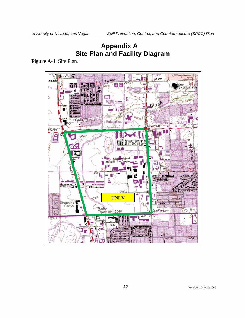
University of Nevada, Las Vegas Spill Prevention, Control, and Countermeasure (SPCC) Plan
Version 1.0, 6/22/2008 -42-
Appendix A Site Plan and Facility Diagram
Figure A-1: Site Plan.
UNLV
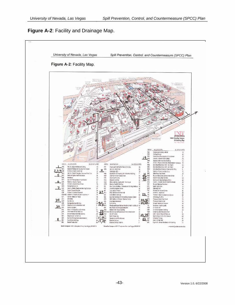
University of Nevada, Las Vegas Spill Prevention, Control, and Countermeasure (SPCC) Plan Figure A-2: Facility and Drainage Map.
Version 1.0, 6/22/2008
-43-
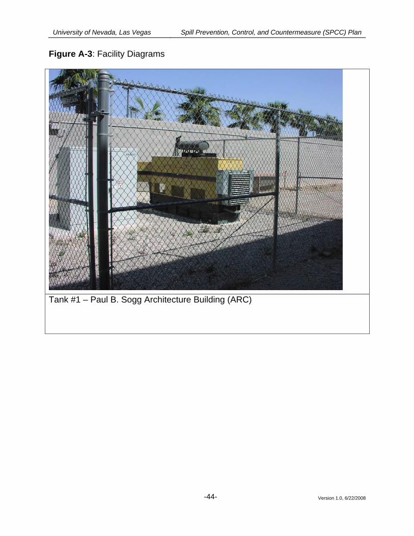
University of Nevada, Las Vegas Spill Prevention, Control, and Countermeasure (SPCC) Plan Figure A-3: Facility Diagrams
Tank #1 – Paul B. Sogg Architecture Building (ARC)
Version 1.0, 6/22/2008
-44-
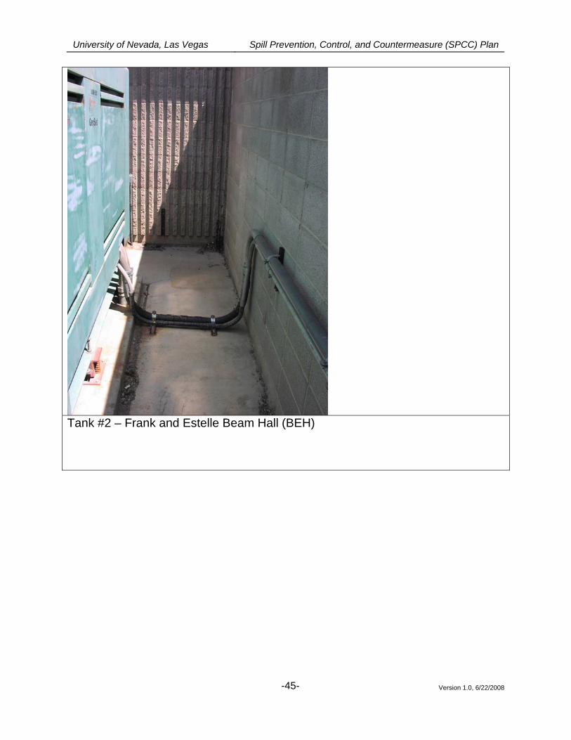
University of Nevada, Las Vegas Spill Prevention, Control, and Countermeasure (SPCC) Plan
Tank #2 – Frank and Estelle Beam Hall (BEH)
Version 1.0, 6/22/2008
-45-
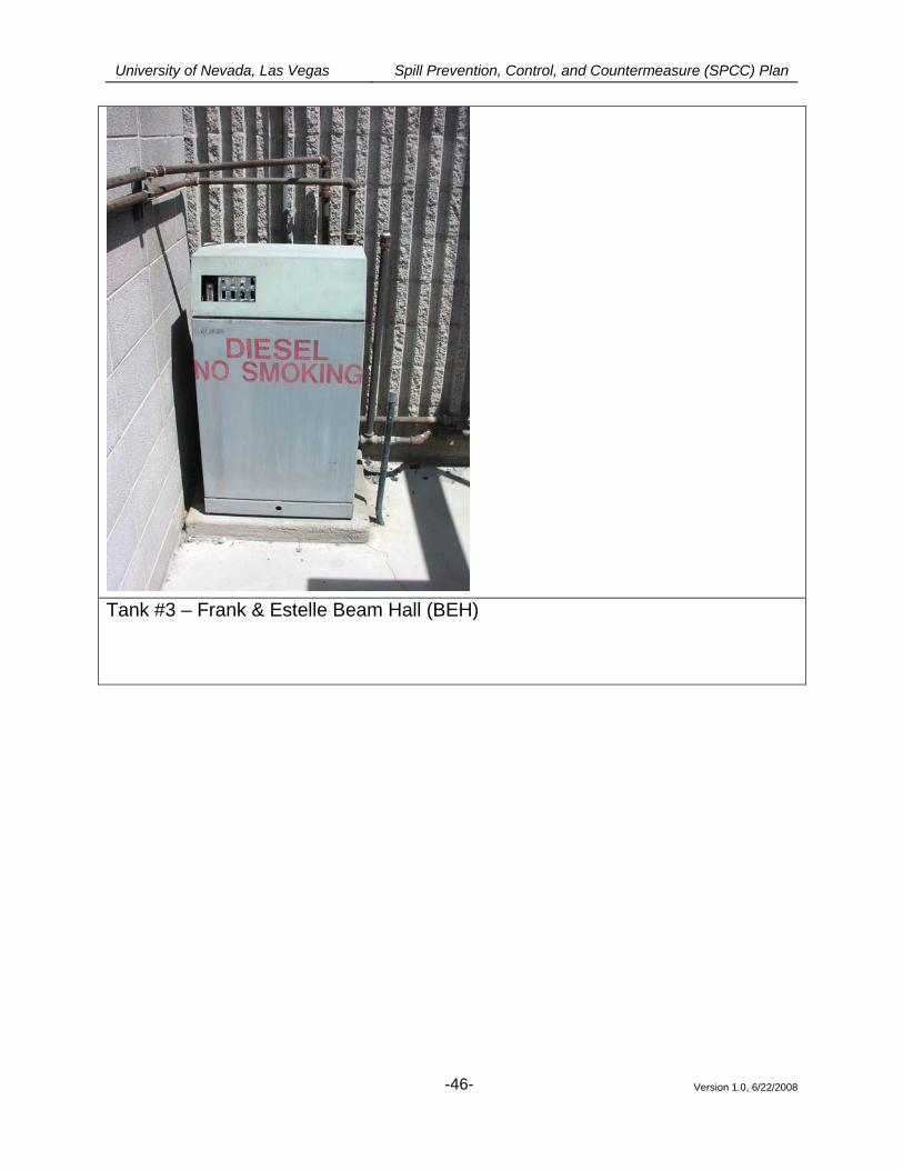
University of Nevada, Las Vegas Spill Prevention, Control, and Countermeasure (SPCC) Plan
Tank #3 – Frank & Estelle Beam Hall (BEH)
Version 1.0, 6/22/2008
-46-
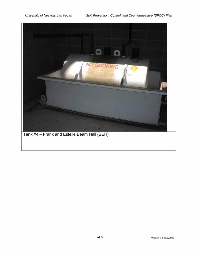
University of Nevada, Las Vegas Spill Prevention, Control, and Countermeasure (SPCC) Plan
Tank #4 – Frank and Estelle Beam Hall (BEH)
Version 1.0, 6/22/2008
-47-
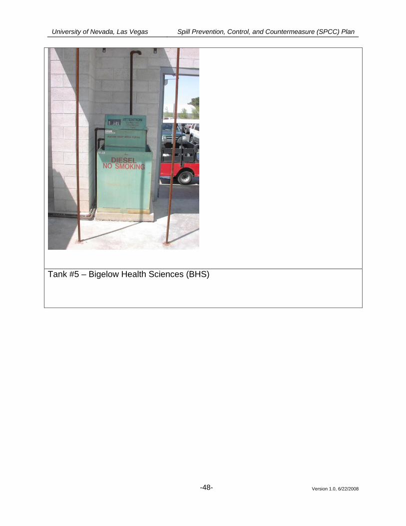
University of Nevada, Las Vegas Spill Prevention, Control, and Countermeasure (SPCC) Plan
Tank #5 – Bigelow Health Sciences (BHS)
Version 1.0, 6/22/2008
-48-
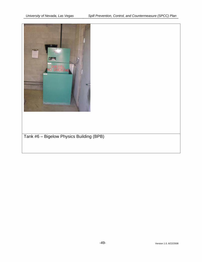
University of Nevada, Las Vegas Spill Prevention, Control, and Countermeasure (SPCC) Plan
Tank #6 – Bigelow Physics Building (BPB)
Version 1.0, 6/22/2008
-49-
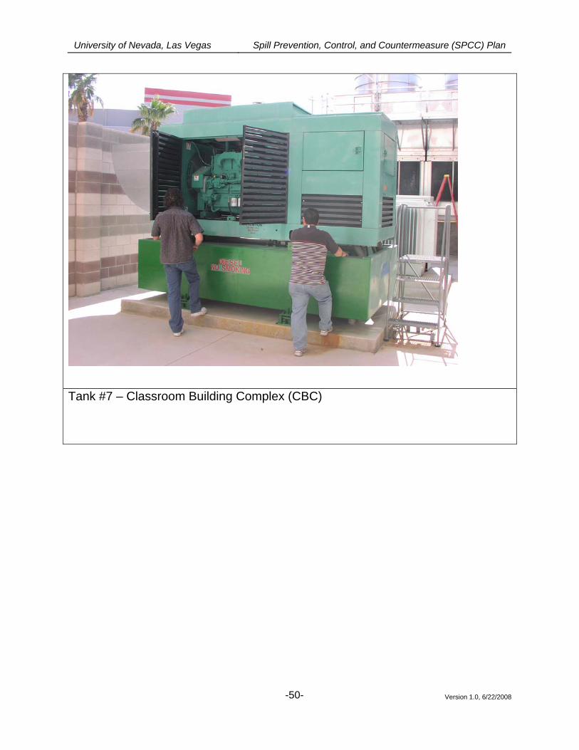
University of Nevada, Las Vegas Spill Prevention, Control, and Countermeasure (SPCC) Plan
Tank #7 – Classroom Building Complex (CBC)
Version 1.0, 6/22/2008
-50-
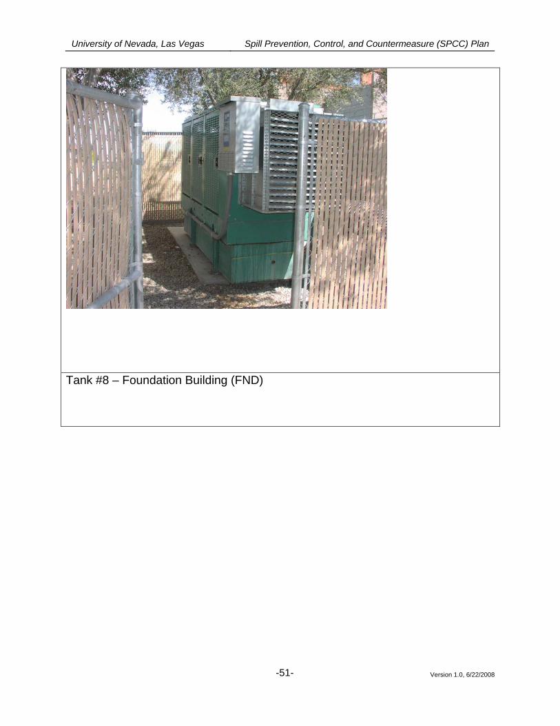
University of Nevada, Las Vegas Spill Prevention, Control, and Countermeasure (SPCC) Plan
Tank #8 – Foundation Building (FND)
Version 1.0, 6/22/2008
-51-
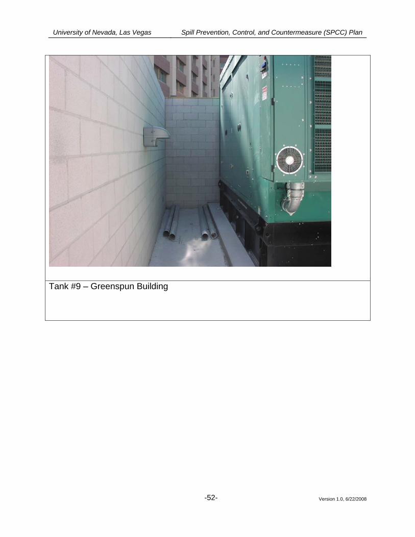
University of Nevada, Las Vegas Spill Prevention, Control, and Countermeasure (SPCC) Plan
Version 1.0, 6/22/2008
-52-
Tank #9 – Greenspun Building
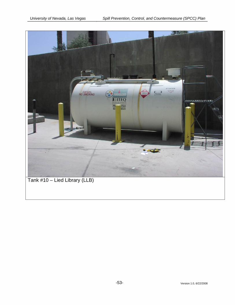
University of Nevada, Las Vegas Spill Prevention, Control, and Countermeasure (SPCC) Plan
Version 1.0, 6/22/2008
-53-
Tank #10 – Lied Library (LLB)
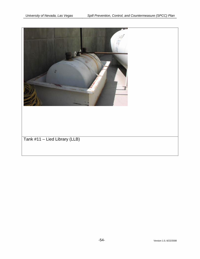
University of Nevada, Las Vegas Spill Prevention, Control, and Countermeasure (SPCC) Plan
Version 1.0, 6/22/2008
-54-
Tank #11 – Lied Library (LLB)
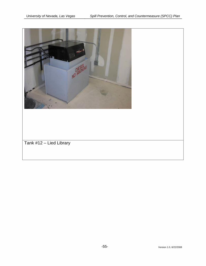
University of Nevada, Las Vegas Spill Prevention, Control, and Countermeasure (SPCC) Plan
Version 1.0, 6/22/2008
-55-
Tank #12 – Lied Library
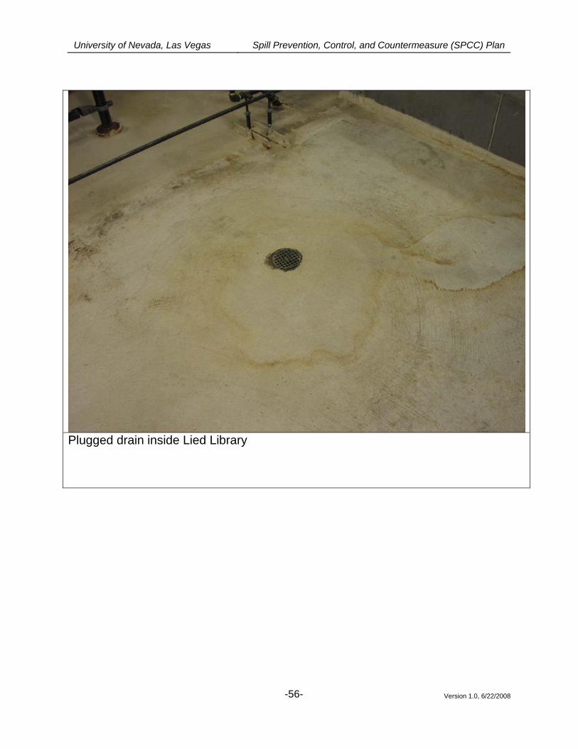
University of Nevada, Las Vegas Spill Prevention, Control, and Countermeasure (SPCC) Plan
Version 1.0, 6/22/2008
-56-
Plugged drain inside Lied Library
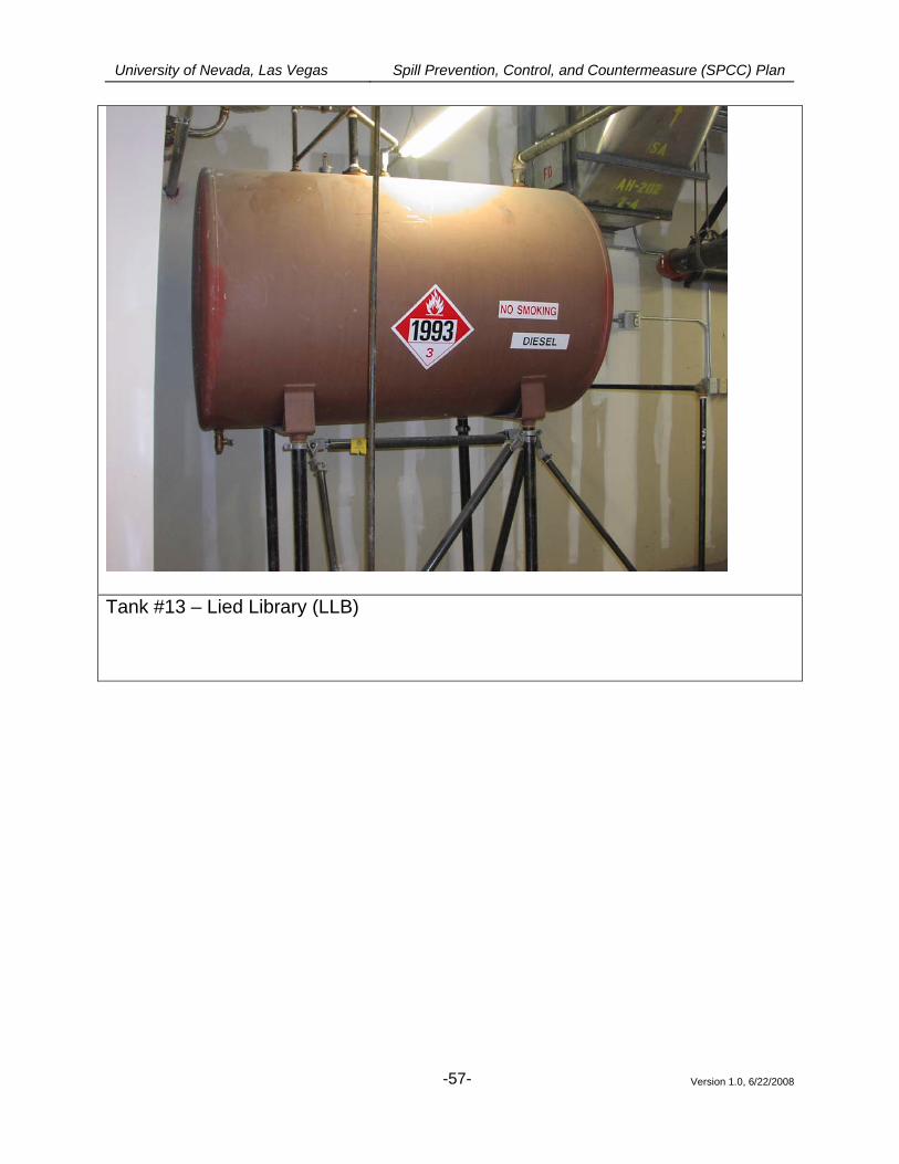
University of Nevada, Las Vegas Spill Prevention, Control, and Countermeasure (SPCC) Plan
Version 1.0, 6/22/2008
-57-
Tank #13 – Lied Library (LLB)
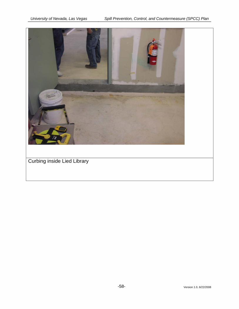
University of Nevada, Las Vegas Spill Prevention, Control, and Countermeasure (SPCC) Plan
Version 1.0, 6/22/2008
-58-
Curbing inside Lied Library
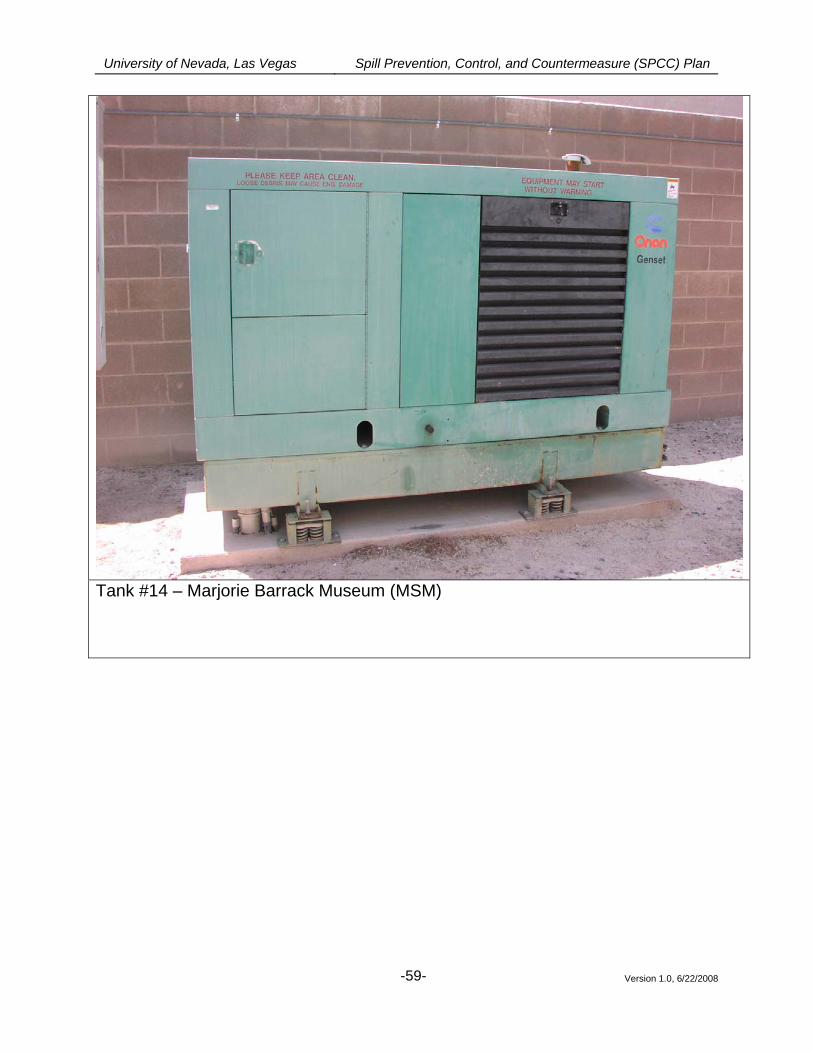
University of Nevada, Las Vegas Spill Prevention, Control, and Countermeasure (SPCC) Plan
Version 1.0, 6/22/2008
-59-
Tank #14 – Marjorie Barrack Museum (MSM)
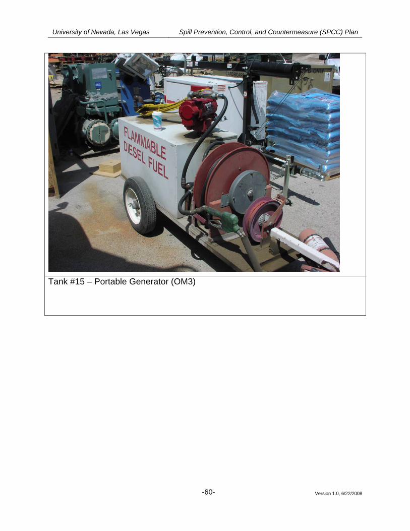
University of Nevada, Las Vegas Spill Prevention, Control, and Countermeasure (SPCC) Plan
Version 1.0, 6/22/2008
-60-
Tank #15 – Portable Generator (OM3)
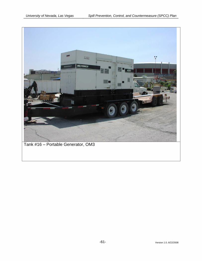
University of Nevada, Las Vegas Spill Prevention, Control, and Countermeasure (SPCC) Plan
Version 1.0, 6/22/2008
-61-
Tank #16 – Portable Generator, OM3
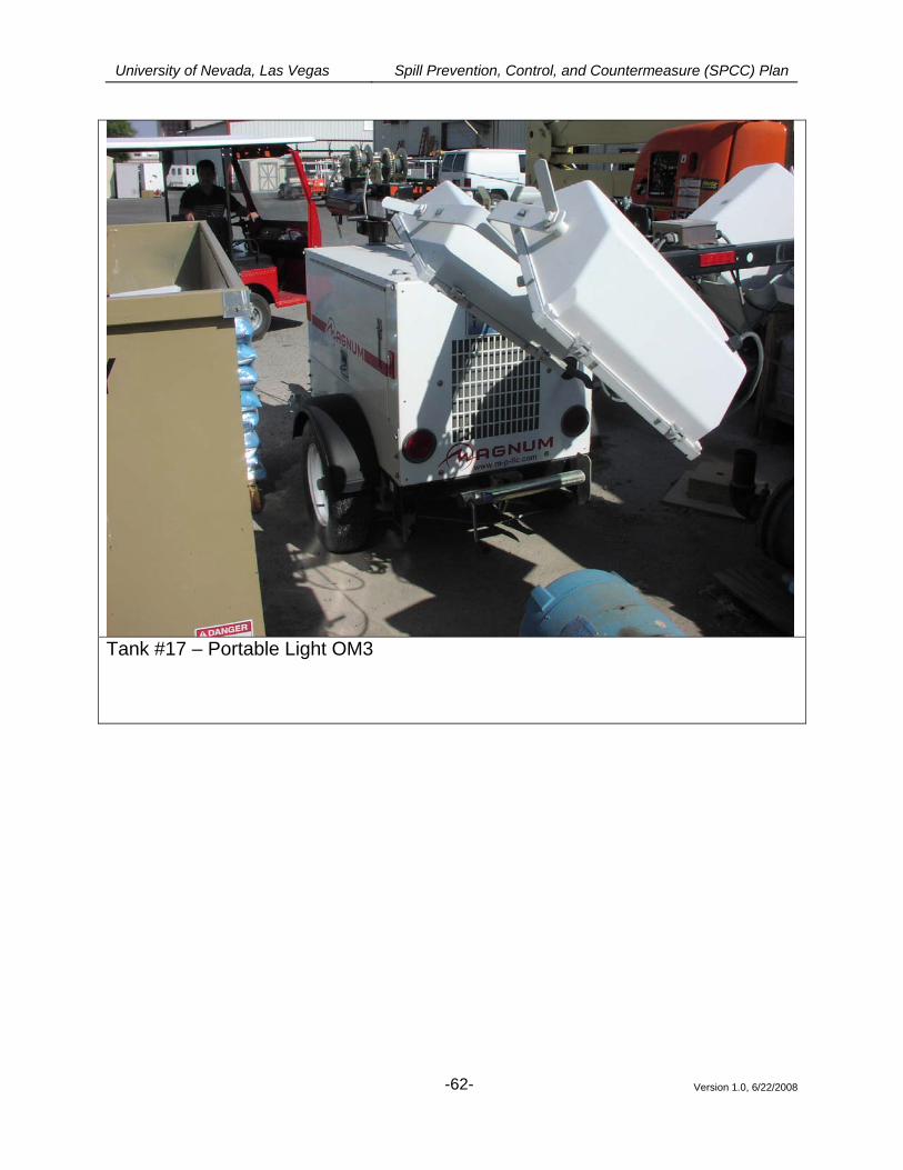
University of Nevada, Las Vegas Spill Prevention, Control, and Countermeasure (SPCC) Plan
Version 1.0, 6/22/2008
-62-
Tank #17 – Portable Light OM3
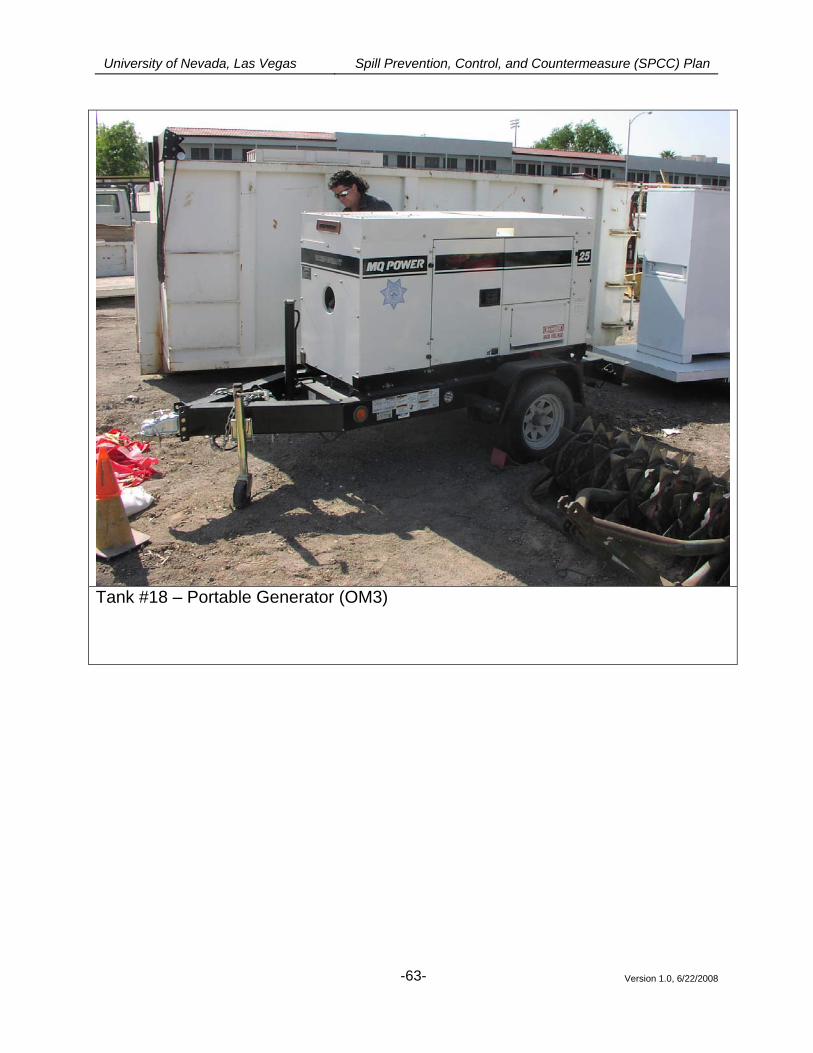
University of Nevada, Las Vegas Spill Prevention, Control, and Countermeasure (SPCC) Plan
Version 1.0, 6/22/2008
-63-
Tank #18 – Portable Generator (OM3)
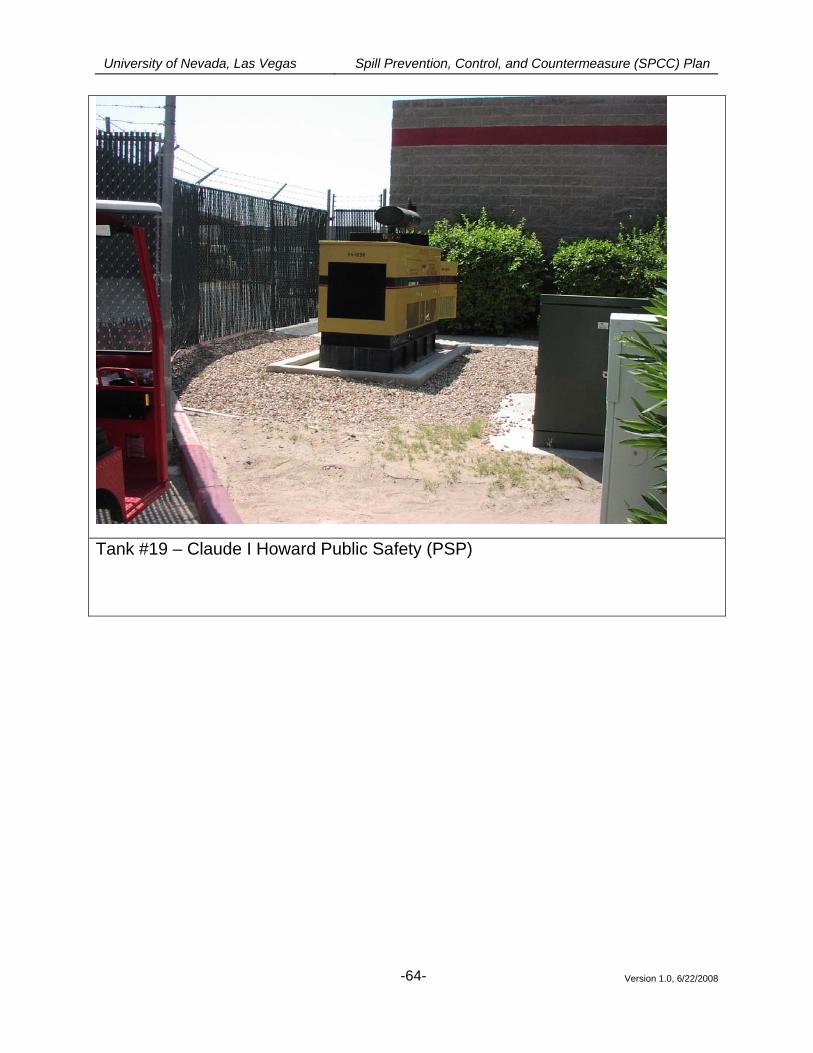
University of Nevada, Las Vegas Spill Prevention, Control, and Countermeasure (SPCC) Plan
Version 1.0, 6/22/2008
-64-
Tank #19 – Claude I Howard Public Safety (PSP)
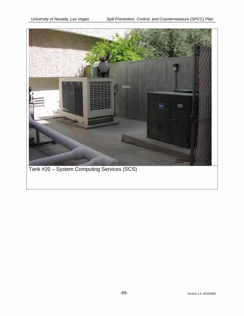
University of Nevada, Las Vegas Spill Prevention, Control, and Countermeasure (SPCC) Plan
Version 1.0, 6/22/2008
-65-
Tank #20 – System Computing Services (SCS)
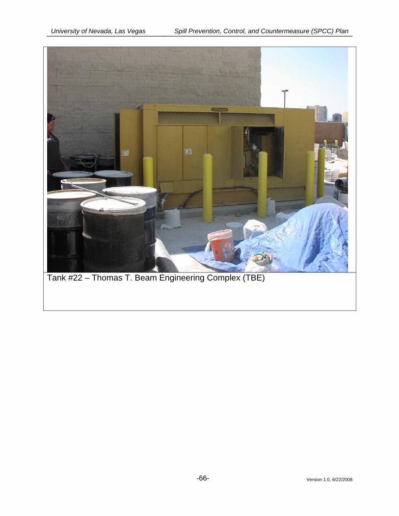
University of Nevada, Las Vegas Spill Prevention, Control, and Countermeasure (SPCC) Plan
Version 1.0, 6/22/2008
-66-
Tank #22 – Thomas T. Beam Engineering Complex (TBE)
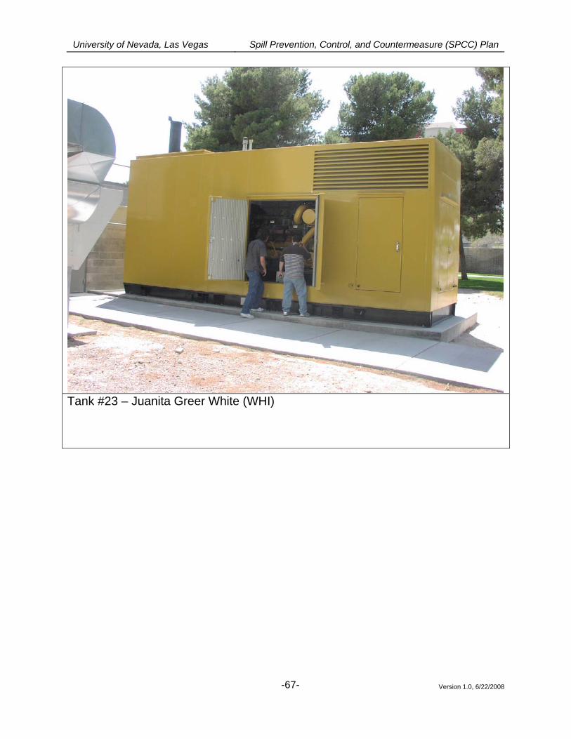
University of Nevada, Las Vegas Spill Prevention, Control, and Countermeasure (SPCC) Plan
Version 1.0, 6/22/2008
-67-
Tank #23 – Juanita Greer White (WHI)
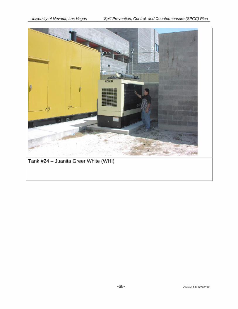
University of Nevada, Las Vegas Spill Prevention, Control, and Countermeasure (SPCC) Plan
Version 1.0, 6/22/2008
-68-
Tank #24 – Juanita Greer White (WHI)
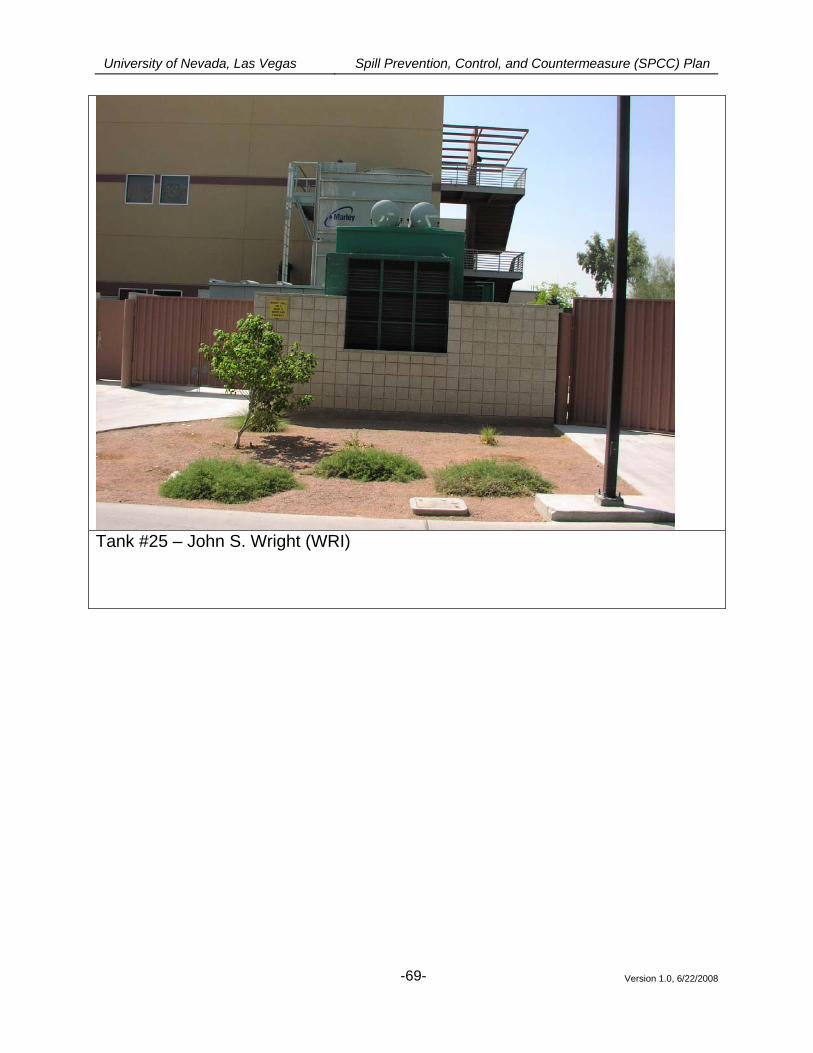
University of Nevada, Las Vegas Spill Prevention, Control, and Countermeasure (SPCC) Plan
Version 1.0, 6/22/2008
-69-
Tank #25 – John S. Wright (WRI)
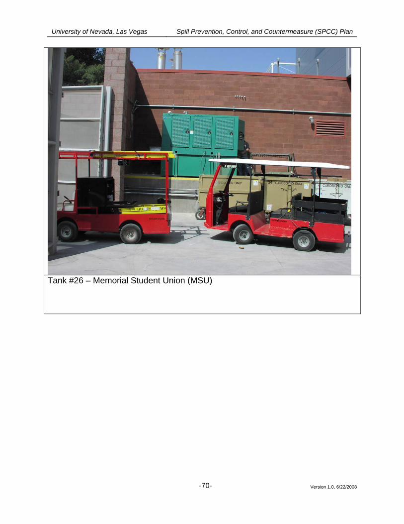
University of Nevada, Las Vegas Spill Prevention, Control, and Countermeasure (SPCC) Plan
Version 1.0, 6/22/2008
-70-
Tank #26 – Memorial Student Union (MSU)
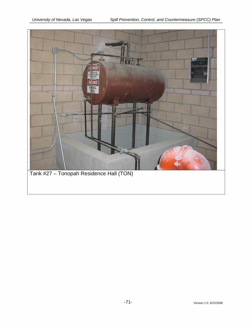
University of Nevada, Las Vegas Spill Prevention, Control, and Countermeasure (SPCC) Plan
Version 1.0, 6/22/2008
-71-
Tank #27 – Tonopah Residence Hall (TON)
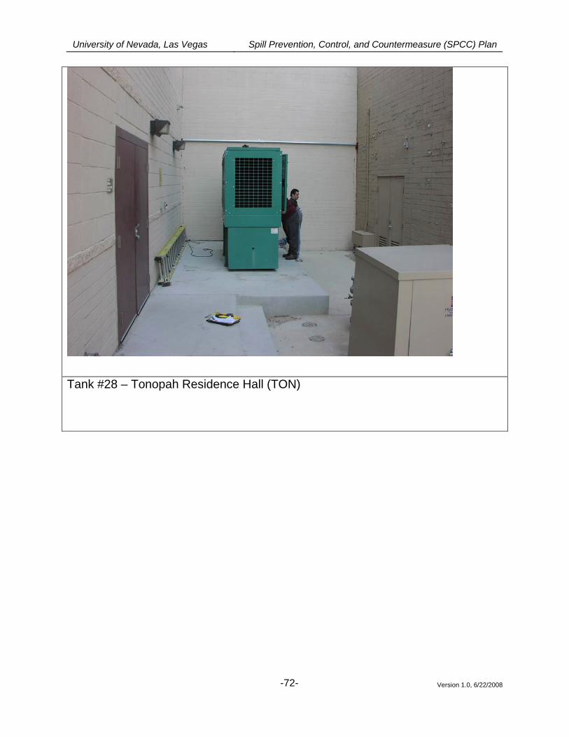
University of Nevada, Las Vegas Spill Prevention, Control, and Countermeasure (SPCC) Plan
Version 1.0, 6/22/2008
-72-
Tank #28 – Tonopah Residence Hall (TON)
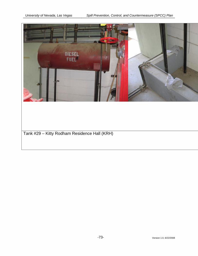
University of Nevada, Las Vegas Spill Prevention, Control, and Countermeasure (SPCC) Plan
Version 1.0, 6/22/2008
-73-
Tank #29 – Kitty Rodham Residence Hall (KRH)
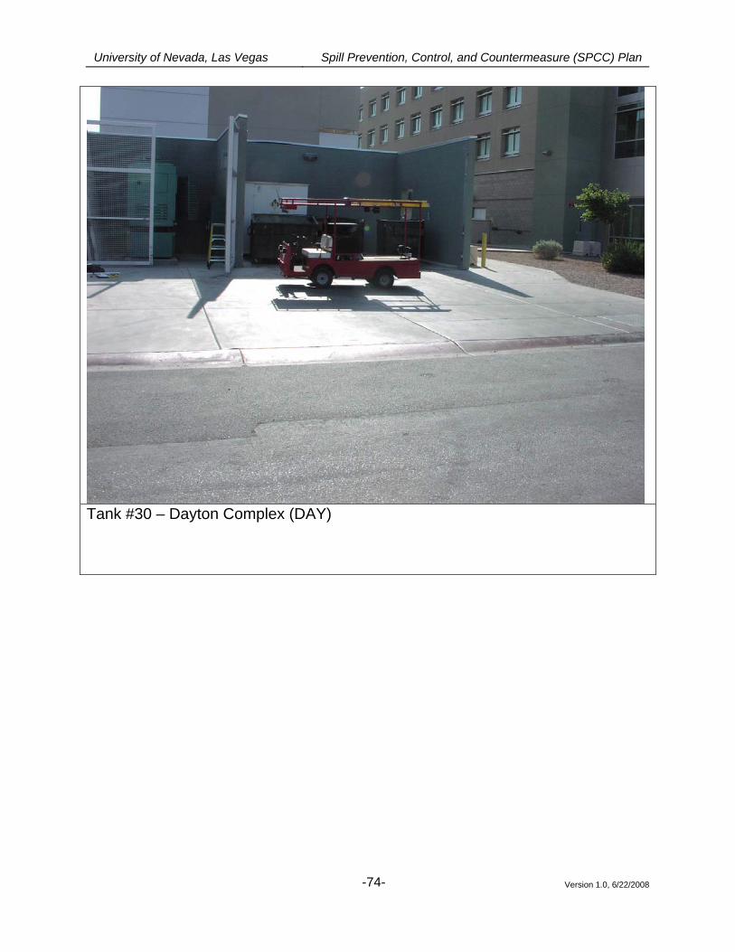
University of Nevada, Las Vegas Spill Prevention, Control, and Countermeasure (SPCC) Plan
Version 1.0, 6/22/2008
-74-
Tank #30 – Dayton Complex (DAY)
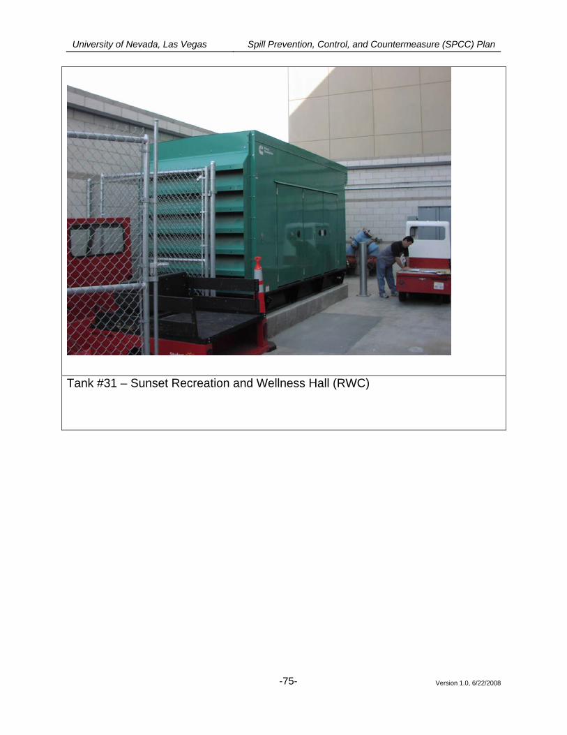
University of Nevada, Las Vegas Spill Prevention, Control, and Countermeasure (SPCC) Plan
Version 1.0, 6/22/2008
-75-
Tank #31 – Sunset Recreation and Wellness Hall (RWC)
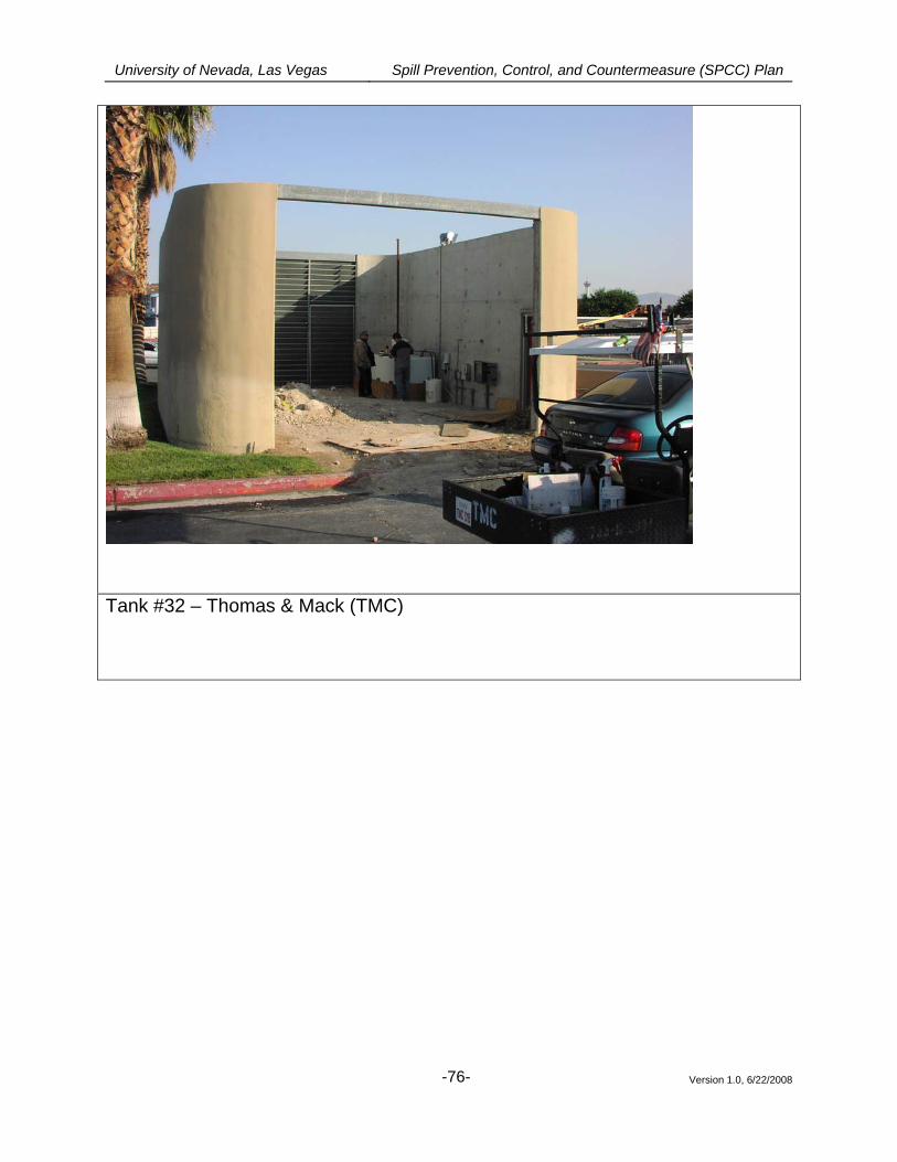
University of Nevada, Las Vegas Spill Prevention, Control, and Countermeasure (SPCC) Plan
Version 1.0, 6/22/2008
-76-
Tank #32 – Thomas & Mack (TMC)
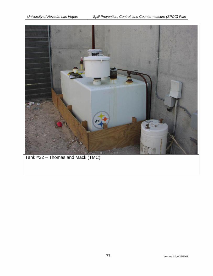
University of Nevada, Las Vegas Spill Prevention, Control, and Countermeasure (SPCC) Plan
Version 1.0, 6/22/2008
-77-
Tank #32 – Thomas and Mack (TMC)
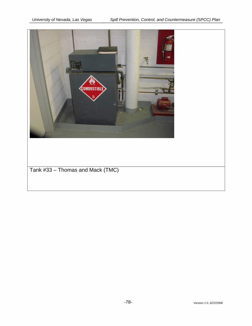
University of Nevada, Las Vegas Spill Prevention, Control, and Countermeasure (SPCC) Plan
Version 1.0, 6/22/2008
-78-
Tank #33 – Thomas and Mack (TMC)
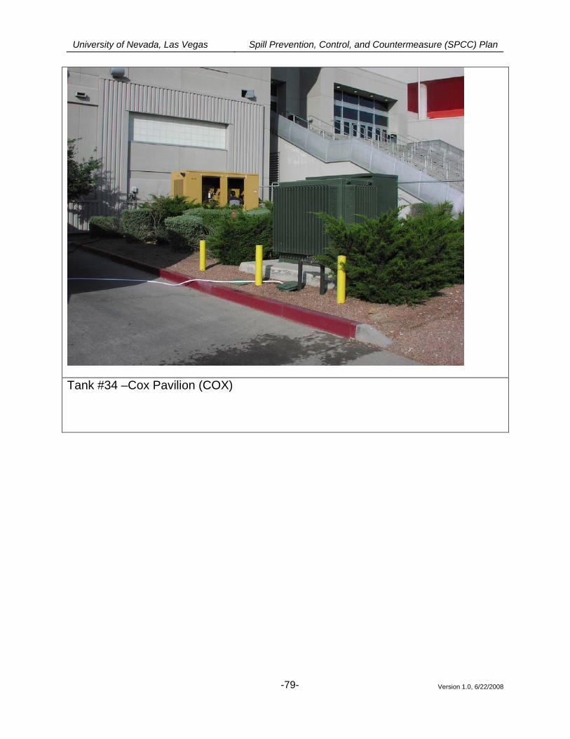
University of Nevada, Las Vegas Spill Prevention, Control, and Countermeasure (SPCC) Plan
Version 1.0, 6/22/2008
-79-
Tank #34 –Cox Pavilion (COX)
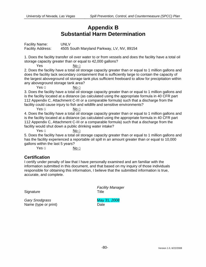
University of Nevada, Las Vegas Spill Prevention, Control, and Countermeasure (SPCC) Plan
Version 1.0, 6/22/2008
-80-
Appendix B Substantial Harm Determination
Facility Name: UNLV Facility Address: 4505 South Maryland Parkway, LV, NV, 89154 1. Does the facility transfer oil over water to or from vessels and does the facility have a total oil storage capacity greater than or equal to 42,000 gallons?
Yes No O 2. Does the facility have a total oil storage capacity greater than or equal to 1 million gallons and does the facility lack secondary containment that is sufficiently large to contain the capacity of the largest aboveground oil storage tank plus sufficient freeboard to allow for precipitation within any aboveground storage tank area? Yes G No O 3. Does the facility have a total oil storage capacity greater than or equal to 1 million gallons and is the facility located at a distance (as calculated using the appropriate formula in 40 CFR part 112 Appendix C, Attachment C-III or a comparable formula) such that a discharge from the facility could cause injury to fish and wildlife and sensitive environments? Yes G No O 4. Does the facility have a total oil storage capacity greater than or equal to 1 million gallons and is the facility located at a distance (as calculated using the appropriate formula in 40 CFR part 112 Appendix C, Attachment C-III or a comparable formula) such that a discharge from the facility would shut down a public drinking water intake? Yes G No O 5. Does the facility have a total oil storage capacity greater than or equal to 1 million gallons and has the facility experienced a reportable oil spill in an amount greater than or equal to 10,000 gallons within the last 5 years? Yes G No O Certification I certify under penalty of law that I have personally examined and am familiar with the information submitted in this document, and that based on my inquiry of those individuals responsible for obtaining this information, I believe that the submitted information is true, accurate, and complete. Facility Manager Signature Title Gary Snodgrass May 31, 2008 Name (type or print) Date
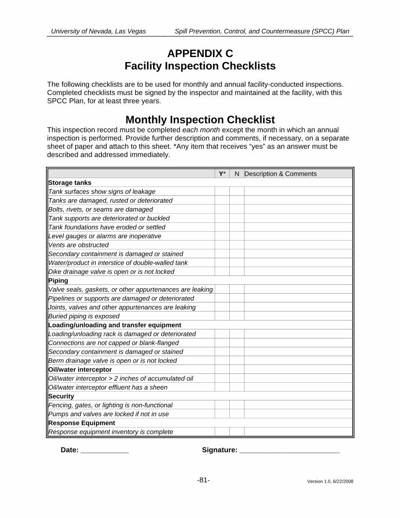
University of Nevada, Las Vegas Spill Prevention, Control, and Countermeasure (SPCC) Plan
Version 1.0, 6/22/2008
-81-
APPENDIX C Facility Inspection Checklists
The following checklists are to be used for monthly and annual facility-conducted inspections. Completed checklists must be signed by the inspector and maintained at the facility, with this SPCC Plan, for at least three years.
Monthly Inspection Checklist This inspection record must be completed each month except the month in which an annual inspection is performed. Provide further description and comments, if necessary, on a separate sheet of paper and attach to this sheet. *Any item that receives “yes” as an answer must be described and addressed immediately.
Y* N Description & Comments Storage tanks Tank surfaces show signs of leakage Tanks are damaged, rusted or deteriorated Bolts, rivets, or seams are damaged Tank supports are deteriorated or buckled Tank foundations have eroded or settled Level gauges or alarms are inoperative Vents are obstructed Secondary containment is damaged or stained Water/product in interstice of double-walled tank Dike drainage valve is open or is not locked Piping Valve seals, gaskets, or other appurtenances are leaking Pipelines or supports are damaged or deteriorated Joints, valves and other appurtenances are leaking Buried piping is exposed Loading/unloading and transfer equipment Loading/unloading rack is damaged or deteriorated Connections are not capped or blank-flanged Secondary containment is damaged or stained Berm drainage valve is open or is not locked Oil/water interceptor Oil/water interceptor > 2 inches of accumulated oil Oil/water interceptor effluent has a sheen Security Fencing, gates, or lighting is non-functional Pumps and valves are locked if not in use Response Equipment Response equipment inventory is complete
Date: ____________ Signature: _________________________
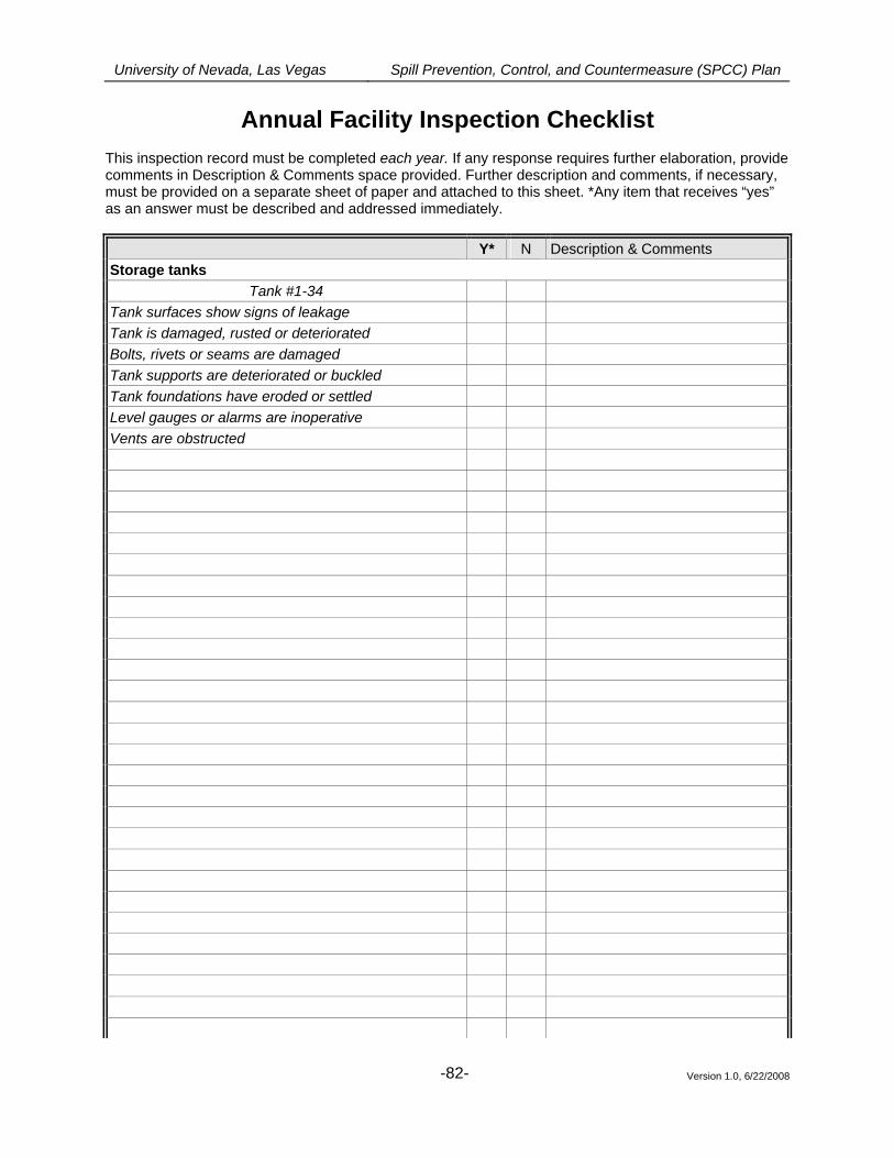
University of Nevada, Las Vegas Spill Prevention, Control, and Countermeasure (SPCC) Plan
Version 1.0, 6/22/2008
-82-
Annual Facility Inspection Checklist
This inspection record must be completed each year. If any response requires further elaboration, provide comments in Description & Comments space provided. Further description and comments, if necessary, must be provided on a separate sheet of paper and attached to this sheet. *Any item that receives “yes” as an answer must be described and addressed immediately.
Y* N Description & Comments Storage tanks
Tank #1-34 Tank surfaces show signs of leakage Tank is damaged, rusted or deteriorated Bolts, rivets or seams are damaged Tank supports are deteriorated or buckled Tank foundations have eroded or settled Level gauges or alarms are inoperative Vents are obstructed
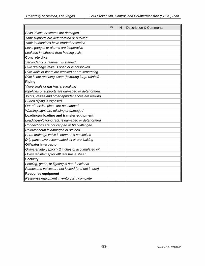
University of Nevada, Las Vegas Spill Prevention, Control, and Countermeasure (SPCC) Plan
Version 1.0, 6/22/2008
-83-
Y* N Description & Comments Bolts, rivets, or seams are damaged Tank supports are deteriorated or buckled Tank foundations have eroded or settled Level gauges or alarms are inoperative Leakage in exhaust from heating coils Concrete dike Secondary containment is stained Dike drainage valve is open or is not locked Dike walls or floors are cracked or are separating Dike is not retaining water (following large rainfall) Piping Valve seals or gaskets are leaking Pipelines or supports are damaged or deteriorated Joints, valves and other appurtenances are leaking Buried piping is exposed Out-of-service pipes are not capped Warning signs are missing or damaged Loading/unloading and transfer equipment Loading/unloading rack is damaged or deteriorated Connections are not capped or blank-flanged Rollover berm is damaged or stained Berm drainage valve is open or is not locked Drip pans have accumulated oil or are leaking Oil/water interceptor Oil/water interceptor > 2 inches of accumulated oil Oil/water interceptor effluent has a sheen Security Fencing, gates, or lighting is non-functional Pumps and valves are not locked (and not in use) Response equipment Response equipment inventory is incomplete
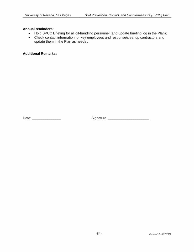
University of Nevada, Las Vegas Spill Prevention, Control, and Countermeasure (SPCC) Plan
Version 1.0, 6/22/2008
-84-
Annual reminders:
• Hold SPCC Briefing for all oil-handling personnel (and update briefing log in the Plan); • Check contact information for key employees and response/cleanup contractors and
update them in the Plan as needed;
Additional Remarks: Date: _______________ Signature: _____________________
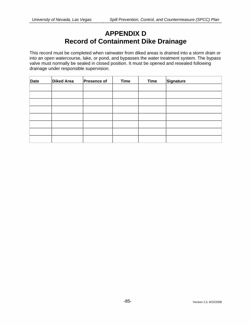
University of Nevada, Las Vegas Spill Prevention, Control, and Countermeasure (SPCC) Plan
Version 1.0, 6/22/2008
-85-
APPENDIX D Record of Containment Dike Drainage
This record must be completed when rainwater from diked areas is drained into a storm drain or into an open watercourse, lake, or pond, and bypasses the water treatment system. The bypass valve must normally be sealed in closed position. It must be opened and resealed following drainage under responsible supervision.
Date Diked Area Presence of Time Time Signature
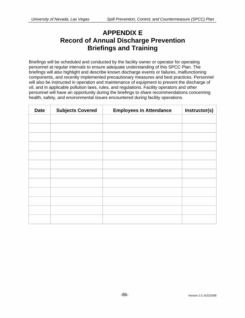
University of Nevada, Las Vegas Spill Prevention, Control, and Countermeasure (SPCC) Plan
Version 1.0, 6/22/2008
-86-
APPENDIX E Record of Annual Discharge Prevention
Briefings and Training Briefings will be scheduled and conducted by the facility owner or operator for operating personnel at regular intervals to ensure adequate understanding of this SPCC Plan. The briefings will also highlight and describe known discharge events or failures, malfunctioning components, and recently implemented precautionary measures and best practices. Personnel will also be instructed in operation and maintenance of equipment to prevent the discharge of oil, and in applicable pollution laws, rules, and regulations. Facility operators and other personnel will have an opportunity during the briefings to share recommendations concerning health, safety, and environmental issues encountered during facility operations.
Date Subjects Covered Employees in Attendance Instructor(s)
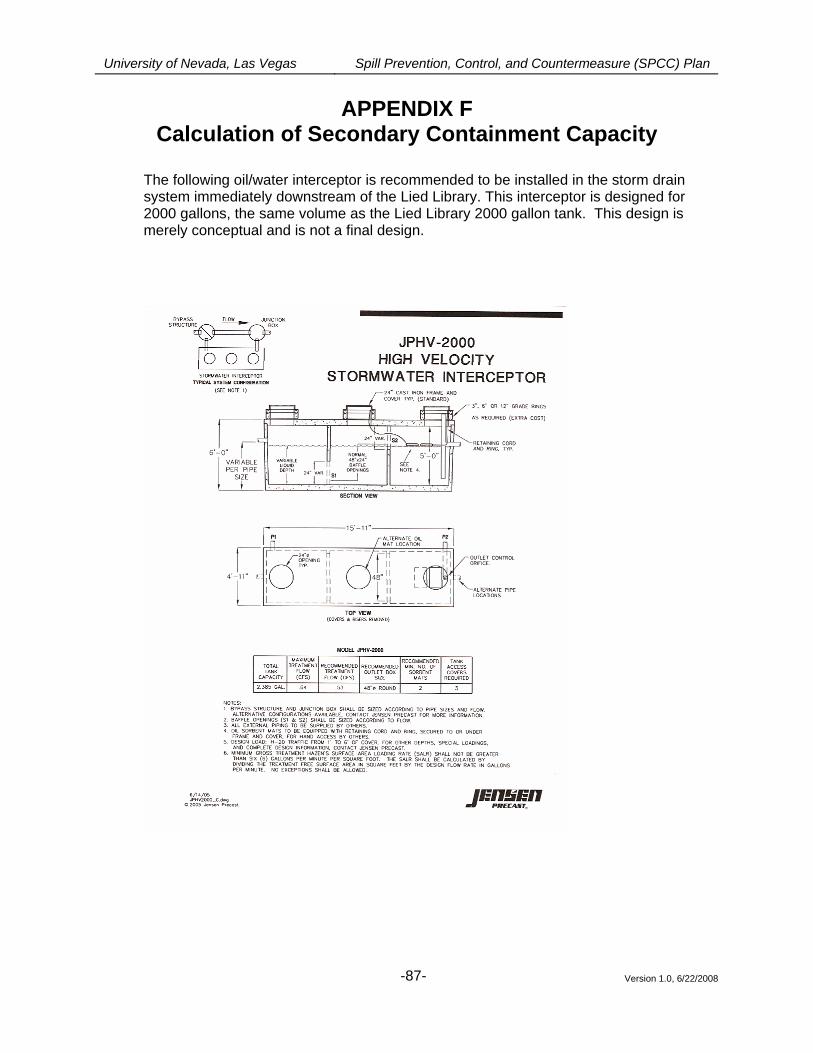
University of Nevada, Las Vegas Spill Prevention, Control, and Countermeasure (SPCC) Plan
Version 1.0, 6/22/2008
-87-
APPENDIX F Calculation of Secondary Containment Capacity
The following oil/water interceptor is recommended to be installed in the storm drain system immediately downstream of the Lied Library. This interceptor is designed for 2000 gallons, the same volume as the Lied Library 2000 gallon tank. This design is merely conceptual and is not a final design.
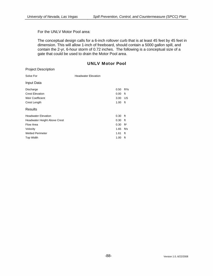
University of Nevada, Las Vegas Spill Prevention, Control, and Countermeasure (SPCC) Plan
Version 1.0, 6/22/2008
-88-
For the UNLV Motor Pool area: The conceptual design calls for a 6-inch rollover curb that is at least 45 feet by 45 feet in dimension. This will allow 1-inch of freeboard, should contain a 5000 gallon spill, and contain the 2-yr, 6-hour storm of 0.72 inches. The following is a conceptual size of a gate that could be used to drain the Motor Pool area.
UNLV Motor Pool Project Description
Solve For Headwater Elevation
Input Data
Discharge 0.50 ft³/s Crest Elevation 0.00 ft Weir Coefficient 3.00 US Crest Length 1.00 ft
Results
Headwater Elevation 0.30 ft Headwater Height Above Crest 0.30 ft Flow Area 0.30 ft² Velocity 1.65 ft/s Wetted Perimeter 1.61 ft Top Width 1.00 ft

University of Nevada, Las Vegas Spill Prevention, Control, and Countermeasure (SPCC) Plan
Version 1.0, 6/22/2008
-89-
For the OM3 Area: The conceptual design calls for a 4-inch dike that is at least large enough to contain the single walled tanks. This will allow 1-inch of freeboard, should contain a 500 gallon spill, and contain the 2-yr, 6-hour storm of 0.72 inches. The following is a conceptual size of a gate that could be used to drain the OM3 Pool area.
UNLV OM3 Project Description
Solve For Headwater Elevation
Input Data
Discharge 0.33 ft³/s Crest Elevation 0.00 ft Weir Coefficient 3.00 US Crest Length 1.00 ft
Results
Headwater Elevation 0.23 ft Headwater Height Above Crest 0.23 ft Flow Area 0.23 ft² Velocity 1.44 ft/s Wetted Perimeter 1.46 ft Top Width 1.00 ft
University of Nevada, Las Vegas Spill Prevention, Control, and Countermeasure (SPCC) Plan
Version 1.0, 6/22/2008
-90-
APPENDIX G Records of Tank Integrity and Pressure Tests
Attach copies of official records of tank integrity and pressure tests.
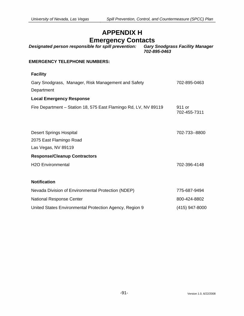
University of Nevada, Las Vegas Spill Prevention, Control, and Countermeasure (SPCC) Plan
Version 1.0, 6/22/2008
-91-
APPENDIX H Emergency Contacts
Designated person responsible for spill prevention: Gary Snodgrass Facility Manager 702-895-0463
EMERGENCY TELEPHONE NUMBERS:
Facility
Gary Snodgrass, Manager, Risk Management and Safety
Department
702-895-0463
Local Emergency Response
Fire Department – Station 18, 575 East Flamingo Rd, LV, NV 89119
911 or 702-455-7311
Desert Springs Hospital
2075 East Flamingo Road
Las Vegas, NV 89119
702-733--8800
Response/Cleanup Contractors
H2O Environmental 702-396-4148
Notification
Nevada Division of Environmental Protection (NDEP) 775-687-9494
National Response Center 800-424-8802
United States Environmental Protection Agency, Region 9 (415) 947-8000
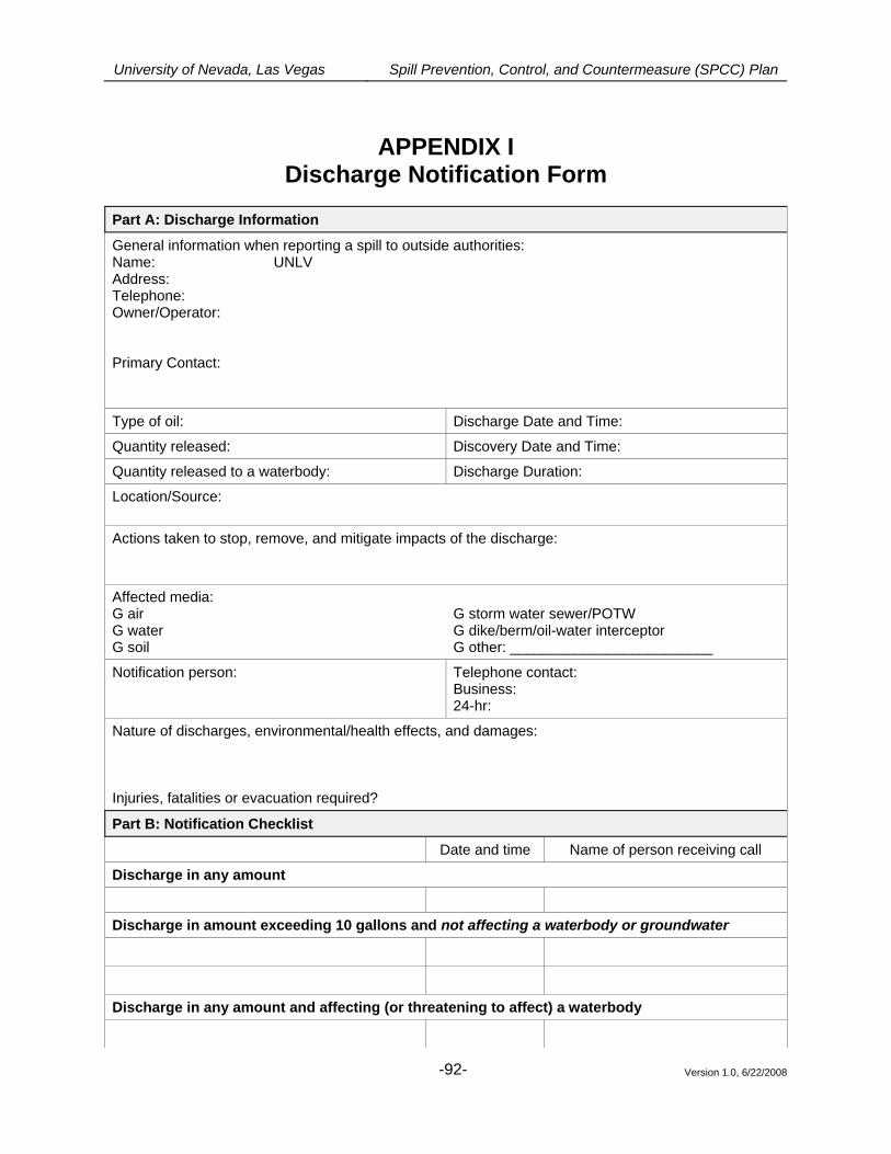
University of Nevada, Las Vegas Spill Prevention, Control, and Countermeasure (SPCC) Plan
Version 1.0, 6/22/2008
-92-
APPENDIX I
Discharge Notification Form
Part A: Discharge Information
General information when reporting a spill to outside authorities: Name: UNLV Address: Telephone: Owner/Operator:
Primary Contact:
Type of oil: Discharge Date and Time:
Quantity released: Discovery Date and Time:
Quantity released to a waterbody: Discharge Duration:
Location/Source:
Actions taken to stop, remove, and mitigate impacts of the discharge:
Affected media: G air G water G soil
G storm water sewer/POTW G dike/berm/oil-water interceptor G other: _________________________
Notification person: Telephone contact: Business: 24-hr:
Nature of discharges, environmental/health effects, and damages: Injuries, fatalities or evacuation required?
Part B: Notification Checklist
Date and time Name of person receiving call
Discharge in any amount
Discharge in amount exceeding 10 gallons and not affecting a waterbody or groundwater Discharge in any amount and affecting (or threatening to affect) a waterbody
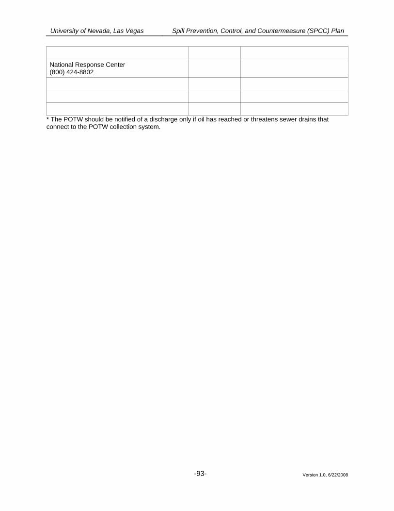
University of Nevada, Las Vegas Spill Prevention, Control, and Countermeasure (SPCC) Plan
Version 1.0, 6/22/2008
-93-
National Response Center (800) 424-8802
* The POTW should be notified of a discharge only if oil has reached or threatens sewer drains that connect to the POTW collection system.
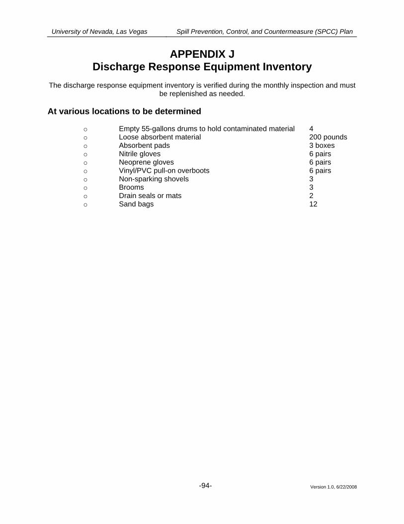
University of Nevada, Las Vegas Spill Prevention, Control, and Countermeasure (SPCC) Plan
Version 1.0, 6/22/2008
-94-
APPENDIX J Discharge Response Equipment Inventory
The discharge response equipment inventory is verified during the monthly inspection and must
be replenished as needed.
At various locations to be determined
o Empty 55-gallons drums to hold contaminated material 4 o Loose absorbent material 200 pounds o Absorbent pads 3 boxes o Nitrile gloves 6 pairs o Neoprene gloves 6 pairs o Vinyl/PVC pull-on overboots 6 pairs o Non-sparking shovels 3 o Brooms 3 o Drain seals or mats 2 o Sand bags 12
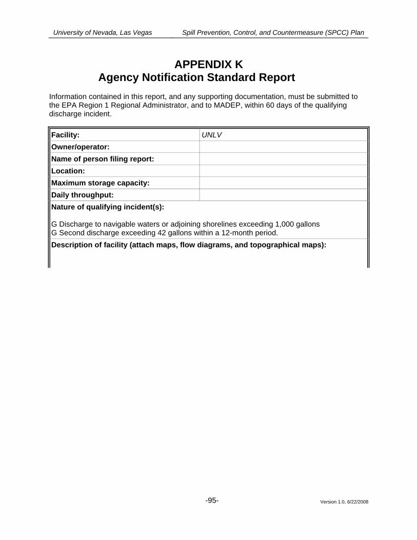
University of Nevada, Las Vegas Spill Prevention, Control, and Countermeasure (SPCC) Plan
Version 1.0, 6/22/2008
-95-
APPENDIX K
Agency Notification Standard Report Information contained in this report, and any supporting documentation, must be submitted to the EPA Region 1 Regional Administrator, and to MADEP, within 60 days of the qualifying discharge incident.
Facility: UNLV Owner/operator:
Name of person filing report: Location:
Maximum storage capacity: Daily throughput: Nature of qualifying incident(s): G Discharge to navigable waters or adjoining shorelines exceeding 1,000 gallons G Second discharge exceeding 42 gallons within a 12-month period. Description of facility (attach maps, flow diagrams, and topographical maps):
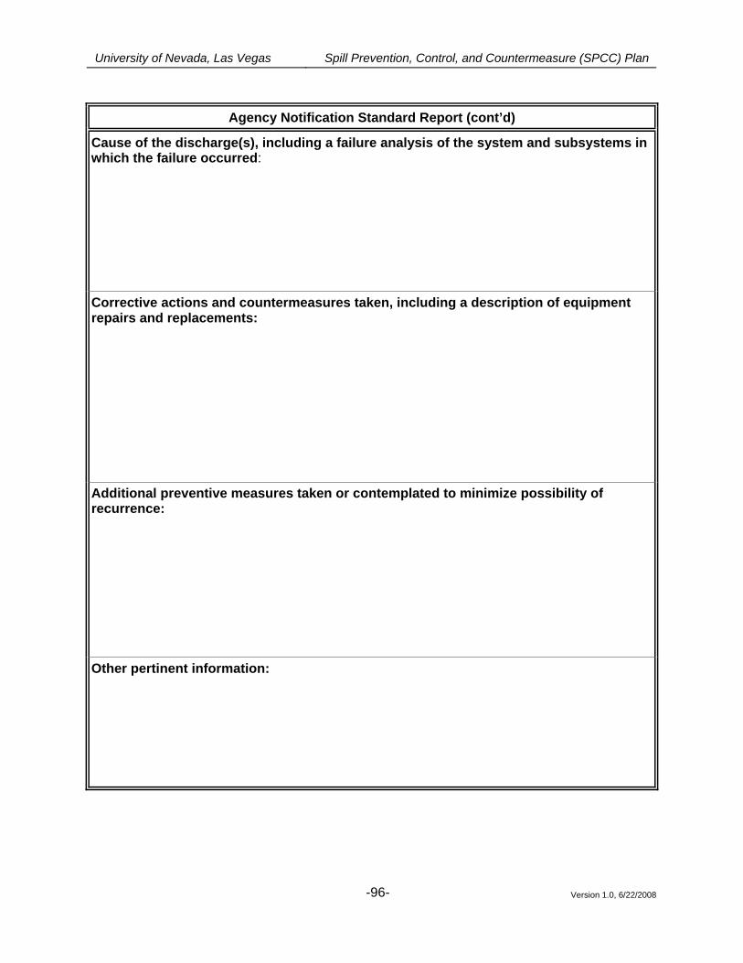
University of Nevada, Las Vegas Spill Prevention, Control, and Countermeasure (SPCC) Plan
Version 1.0, 6/22/2008
-96-
Agency Notification Standard Report (cont’d)
Cause of the discharge(s), including a failure analysis of the system and subsystems in which the failure occurred: Corrective actions and countermeasures taken, including a description of equipment repairs and replacements: Additional preventive measures taken or contemplated to minimize possibility of recurrence: Other pertinent information: